influence of fasteners and connections flexibility on ... · the idea of stressed skin design...
TRANSCRIPT

Technical Sciences, 2018, 21(2), 131–148
INFLUENCE OF FASTENERS AND CONNECTIONS FLEXIBILITY ON DEFLECTIONS OF STEEL BUILDING
INCLUDING THE STRESSED SKIN EFFECT
Natalia Korcz, Elżbieta Urbańska-GalewskaDepartment of Metal Structures and Construction Management
Faculty of Civil and Environmental Engineering Gdańsk University of Technology
Received 8 May 2017; accepted 22 January 2018; available online 14 March 2018.
K e y w o r d s : steel structures, diaphragm design, trapezoidal sheeting, orthotropic plate mo-del, structure displacement, fastener flexibility.
A b s t r a c t
The paper presents the analysis of the influence of fasteners and connections flexibility on displacements of symmetrical single-bay pitched-roof steel building, including trapezoidal cladding acting as a diaphragm. The purpose of the article was to compare numerical models with and without taking into consideration fasteners and connections flexibility in order to observe the differences in transverse stiffness of the building during modifying model from the simple one to more complex and precise. The analyses were carried out for the 3D structure. Fasteners and connections were substituted by equivalent beam finite elements. Corrugated sheets were replaced by three types of equivalent orthotropic shell models and the influence of the choice of the model on the stiffness of the building was observed. The results showed that in the analysed structure the flexibility of fasteners and connections has negligible effect on transverse displacements of the building in the case of four sides fastening of the sheeting, however in the case of two sides fastening the influence significantly increases.
AbbreviationsARSA – Autodesk Robot Structural Analysis Professional 2015ER – European Recommendations for the Application of Metal Sheeting Acting as
a Diaphragm. Stressed Skin Design. 1995. ECCS – TC7, TWG 7.5P1 – structural models without cladding T1, T2, T3 – structural models with the stressed skin effect included; without fasteners and con-
nectors (T1), with purlin/rafter connections and shear connector fasteners (T2), with purlin/rafter connections, shear connector fasteners and sheet/purlin fasteners (T3)
Correspondence: Natalia Korcz, Katedra Konstrukcji Metalowych i Zarządzania w Budownic-twie, Wydział Inżynierii Lądowej i Środowiska, Politechnika Gdańska, ul. G. Narutowicza 11/12, 80-233 Gdańsk, e-mail: [email protected]

132 NataliaKorcz,ElżbietaUrbańska-Galewska
Technical Sciences 21(2) 2018
M0, MA, MB – types of sheeting model used in structural models: infinitely rigid plate (M0), pre-defined orthotropic plate with the trapezoid plate geometry selected by user (MA), orthotropic plate with orthotropic matrix calculated and defined by user (MB)
2K/4K – two/four sides fastening of the shear panel∆ – displacement measured in mmc – in-plane shear flexibility of panel measured in mm/kN
Introduction
Trapezoidal cladding of the steel building has an undeniable effect on the stiffness and spatial character of work of the structure and, by extension, on deflections and cross-sectional forces of particular structural members. Although the idea of stressed skin design (diaphragm design) has been widely known for many years, in traditional design it is usually omitted. It seems that the biggest obstacle which hinders the popularity of diaphragm design in engineering practice is the lack of enough universal, verified and simple to apply procedures. More and more effective methods of including the stressed skin effect in structural calculations are still being searched and developed. Examples can be found in Bródka et al. (1999), EN-1993-1-3:2006, European Recommendations (Er) (1995) provided by European Convention for Constructional Steelwork (ECCS), GryniEwicz and SzlEndak (2016a, 2016b), Joó and dunai (2015), lEndvai and Joó (2016), naGy et al. (2015, 2016). The development of numerical tools which support engineers in static and dynamic analysis of the structure brings new capabilities to take into account the diaphragm effect, which seems to be more and more economy-reasonable approach.
The basis of the work on the stressed skin effect is Er (1995) whereby the definition of the diaphragm (shear panel) depends on the orientation of the sheeting spanning in regard to the length of the diaphragm: perpendicular – typical for purlin systems (Fig. 1) or parallel – typical for non-purlin systems. The dimension a of the panel is always perpendicular and the dimension b – parallel to corrugation (Fig. 1). Moreover, the procedures differentiate two static
Fig. 1. Static schemes of the diaphragm: a – panel assembly, b – cantilevered diaphragm

InfluenceofFastenersandConnectionsFlexibilityonDeflectionsofSteelBuilding… 133
Technical Sciences 21(2) 2018
schemes of the diaphragm, depending on the arrangement of vertical bracings (the elements, which bring forces to the foundation, for instance bracings of gable wall). According to this classification „panel assembly” („diaphragm beam”) and „cantilevered diaphragm” can be recognised (see Fig. 1).
The diaphragm is characterised not only by the cross-section of the trape-zoidal sheeting, but also by fasteners: sheet/purlin fasteners, seam fasteners (sheet/sheet fasteners) and sheet/shear connector fasteners. According to ER (1995), shear flexibility of the diaphragm c is the sum of a series of components. The origins of the shear flexibility are demonstrated in the axonometric view in Figure 2. Shear flexibility of the diaphragm is due to:
– sheet deformation: profile distortion (c1,1) and shear strain (c1,2),– fasteners deformation: sheet/purlin fasteners (c2,1), seam fasteners (c2,2)
and connections to rafters (c2,3),– flange forces: axial strain in purlins (c3). Therefore, there are two main aspects of including the diaphragm effect
in 3D numerical analysis of the structure – consideration of the flexibility of:– steel trapezoidal sheets,– fasteners and connections.
Fig. 2. Components of shear flexibility
The conventional ways of including the stressed skin effect, proposed in ER (1995), consider both of these aspects in one tool. According to ER (1995), the flexibility of diaphragm can be substituted by springs located in the plane of the roof, whose stiffness corresponds with the analytically-calculated shear flexibil-ity c of the panel (Fig. 3a, c), what is described for instance by kowalczyk and nowicki (2003). The diaphragm effect in 3D numerical model of the structure can be also included using diagonal bracing model of the roof panel (X type bracing). Then the analytically-calculated shear flexibility c of the diaphragm is implemented in the computational model of the structure by appropriate EA

134 NataliaKorcz,ElżbietaUrbańska-Galewska
Technical Sciences 21(2) 2018
stiffness of the equivalent braces (Fig. 3a, b), which is introduced for example by niEwiadomSki (2011), GoczEk (2013). Nonetheless, more accurate model using more advanced and simultaneously more and more available computa-tional tools are still being searched. Wide-ranging analyses using link elements which connect structural members in order to include the stressed skin effect are submitted by naGy et al. (2016).
Fig. 3. Shear panel models: a – with sheeting, b – with braces (equivalent longitudinal stiffness EA), c – with lateral spring (equivalent flexibility)
Other way to include the stressed skin effect in 3D numerical model of the structure is to substitute trapezoidal sheeting by an orthotropic 2D shell model, which is schematically shown in Figure 4. The idea of this process is to find the equivalent stiffness matrix of orthotropic shell which reflects different stiffness of steel trapezoidal sheeting in perpendicular directions. Obviously this approach is only an approximation, assuming for example the symmetrical cross-section of the cladding and that the dimension of one period of corrugation is small in comparison to the dimension of the sheet. What is more, local changes of stiff-ness are not recognised.
Fig. 4. The idea of substitution the fully 3D-modelled trapezoidal sheeting by the orthotropic 2D shell model according to wEnnBErG et al. (2011)
Different analytical expressions for stiffness matrix of equivalent orthotropic shell for trapezoidal sheeting are known (Bródka et al. 1999, GryniEwicz, SzlEndak 2016a, 2016b, wEnnBErG et al. 2011, Xia et al. 2012). What is more, in computational programs for numerical 3D analysis of the structures

InfluenceofFastenersandConnectionsFlexibilityonDeflectionsofSteelBuilding… 135
Technical Sciences 21(2) 2018
(for instance ARSA, RFEM) the tools (predefined orthotropic shells/plates), which allow the user to select the trapezoidal plate geometry instead of define stiffness matrix of equivalent orthotropic shell, are implemented. Matrix values are calculated by the program on the basis of the geometrical parameters and the user is no longer obliged to calculate the matrix values himself (Autodesk Robot Structural Analysis Professional 2015). It is necessary to emphasize that the analytical procedures for the stiffness matrix of equivalent orthotropic plate for trapezoidal sheeting, both known from the literature and implemented in numerical programs, diverge considerably.
In the article korcz (2017) the comparison and evaluation of numerical models of trapezoidal sheeting, by example of cantilevered diaphragm, is pre-sented. Analyses are run in ARSA. Due to the way of definition, two groups of models are distinguished:
– predefined orthotropic shell with trapezoidal geometry selected by user (MA),– orthotropic shell with orthotropic matrix calculated and defined by user (MB).Analysed models are built by trapezoidal sheeting, purlins, top chords of
truss girders, fasteners and connections. Models (MB) are built using analyti-cal formulas for stiffness matrix of equivalent orthotropic plate for trapezoidal sheeting chosen based on wEnnBErG et al. (2011), Xia et al. (2012), GryniEwicz and SzlEndak (2016a, 2016b). Selected procedures, with all used expressions and the convention of orthotropic directions, are introduced precisely by korcz (2017). In particular, membrane stiffness matrix D value is calculated in com-pliance with formulas (1–6):
𝑫𝑫 = 𝑡𝑡1 − 𝑥𝑥𝑥𝑥 ∙ 𝑥𝑥𝑥𝑥
[𝐸𝐸𝑥𝑥 𝑥𝑥𝑥𝑥 ∙ 𝐸𝐸𝑥𝑥 0
𝑥𝑥𝑥𝑥 ∙ 𝐸𝐸𝑥𝑥 𝐸𝐸𝑥𝑥 00 0 (1 − 𝑥𝑥𝑥𝑥 ∙ 𝑥𝑥𝑥𝑥) ∙ 𝐺𝐺𝑥𝑥𝑥𝑥
] (1)
𝐸𝐸𝑥𝑥 = E ∙𝑙𝑙𝑝𝑝𝑑𝑑 (2)
𝐸𝐸𝑦𝑦 = E ∙𝐼𝐼𝑦𝑦0𝐼𝐼𝑦𝑦
(3)
𝑦𝑦𝑦𝑦 = ∙𝐸𝐸𝑦𝑦𝐸𝐸𝑦𝑦
(4)
𝑥𝑥𝑥𝑥 = (5)
𝐺𝐺𝑥𝑥𝑥𝑥 = 𝑎𝑎𝑏𝑏 ∙ 𝑡𝑡 ∙ (𝑐𝑐1,1 + 𝑐𝑐1,2)
(6)

136 NataliaKorcz,ElżbietaUrbańska-Galewska
Technical Sciences 21(2) 2018
where: t – thickness of trapezoidal sheeting = thickness of equivalent orth-
otropic plate, ν, E – Poisson’s ratio and elasticity modulus of steel material,Iy0 – equivalent plate moment of inertia,Iy – trapezoidal plate section moment of inertia,lp – the developed width of one corrugation,d – width of one corrugation,a,b – dimensions of the shear panel (Fig. 1),c1,1, c1,2 – flexibility components according to ER (1995).
The most important factor, which distinguishes (MA) and (MB) models, is D33 element of the membrane stiffness matrix D (circa 5 times difference). In ARSA-implemented procedures (MA) this element is dependent on cross-sec-tion geometry and material properties only, according to formula (7). In model (MB) formula (8) is used – much more data are taken into account: dimensions of the shear panel (a,b) and flexibility components c1,1 and c1,2 according to ER (1995). In particular, flexible component c1,1 (the result of profile distortion) depends not only on the sheet geometry but also among others on the way of sheet/purlin fastening (in every corrugation/in every double corrugation) and on the number of sheets in the width of the panel assembly.
𝐷𝐷33(MA) =E
2(1 + ) ∙ 𝑡𝑡 ∙𝑑𝑑𝑙𝑙𝑝𝑝
(7)
𝐷𝐷33(MB) = 𝑎𝑎𝑏𝑏 ∙ (𝑐𝑐1,1 + 𝑐𝑐1,2)
(8)
The evaluation of numerical models of trapezoidal sheeting depends on the degree of the agreement between the numerical and analytical results calculated according to ER (1995). In compliance with this criterion, better accuracy char-acterised model (MB), so this model should be used in numerical calculations of the whole structure instead of model (MA).
Likewise, the flexibility of connections and fasteners used in the roof panels has strong effect on the flexibility of the whole roof diaphragm. It can be mod-elled by two perpendicular springs connected to two nodes with zero distance and with stiffness corresponding to the force-displacement relationship of con-nector (usually linear approximation is used in practice), what is described by Bródka et al. (1999).
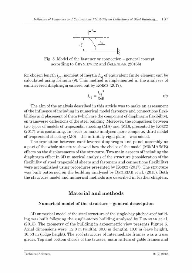
Another approach is to take into consideration not only theoretical slip sof fasteners and other connections, but also their placement, using equivalent can-tilever finite beam elements (Fig. 5), introduced by GryniEwicz and SzlEndak (2016a, 2016b). Knowing theoretical slip s and expression for maximum dis-placement of the cantilever under the concentrated force applied at the free end,
InfluenceofFastenersandConnectionsFlexibilityonDeflectionsofSteelBuilding… 137
Technical Sciences 21(2) 2018
for chosen length leq, moment of inertia Ieq of equivalent finite element can be calculated using formula (9). This method is implemented in the analyses of cantilevered diaphragm carried out by korcz (2017).
𝐼𝐼𝑒𝑒𝑒𝑒 =𝑙𝑙𝑒𝑒𝑒𝑒33𝑠𝑠E (9)
The aim of the analysis described in this article was to make an assessment of the influence of including in numerical model fasteners and connections flexi-bilities and placement of them (which are the component of diaphragm flexibility), on transverse deflections of the steel building. Moreover, the comparison between two types of models of trapezoidal sheeting (MA) and (MB), presented by korcz (2017) was continuing. In order to make analyses more complete, third model of trapezoidal sheeting (M0) – the infinitely rigid plate – was added.
The transition between cantilevered diaphragm and panel assembly as a part of the whole structure showed how the choice of the model (M0/MA/MB) effects on the displacements of the structure. Two main aspects of including the diaphragm effect in 3D numerical analysis of the structure (consideration of the flexibility of steel trapezoidal sheets and fasteners and connections flexibility) were accomplished using procedures presented by korcz (2017). The structure was built patterned on the building analysed by dEniziak et al. (2015). Both the structure model and numerical methods are described in further chapters.
Material and methods
Numerical model of the structure – general description
3D numerical model of the steel structure of the single-bay pitched-roof build-ing was built following the single-storey building analysed by dEniziak et al. (2015). The geometry of the building in axonometric view presents Figure 6. Axial dimensions were: 12.0 m (width), 30.0 m (length), 10.0 m (eave height), 10.53 m (ridge height). The roof structure of intermediate frames was a truss girder. Top and bottom chords of the trusses, main rafters of gable frames and
Fig. 5. Model of the fastener or connection – general concept according to GryniEwicz and SzlEndak (2016b)

138 NataliaKorcz,ElżbietaUrbańska-Galewska
Technical Sciences 21(2) 2018
purlins were made with IPE section, diagonals of the trusses, beams and columns of gable wall with RHS section, bracings with ϕ-bars. Two variants of columns of the main frames were used (HEB300 and HEB200). The other sections were invariable in all models. Specification of the applied elements is presented in Figure 6. The cladding of the roof was made with trapezoidal sheeting shown in Figure 7.
Fig. 6. Geometry and cross-sections of the analysed 3D steel structure
Fig. 7. Trapezoidal sheeting geometry [mm]
Maximal values of deflection of the single-storey building structure in trans-verse direction was observed, so only the wind blowing perpendicular to the length of the building was taken into consideration. Following load cases were considered:
– G – dead loads (generated automatically);– S1 – symmetric snow load; according to EN-1991-1-3:2003; characteristic
value: s = 0.96 kN/m2;– W1 – wind load in the perpendicular direction to the length of the build-
ing with suction on downwind surface and no pressure on upwind surface

InfluenceofFastenersandConnectionsFlexibilityonDeflectionsofSteelBuilding… 139
Technical Sciences 21(2) 2018
of the roof; according to EN-1991-1-4:2004 and National Annex PN-EN-1991- -1-4:2008; characteristic values of loads for particular areas: we,A = –0.97 kN/m2, we,B
= –0.65 kN/m2, we,D= 0.63 kN/m2,we,E = –0.38 kN/m2,we,F= we,G=we,H = = 0 kN/m2, we,I =we,J = –0.49 kN/m2;
– W2 – wind in the perpendicular direction to the length of the building with suction on downwind and upwind surface of the roof; according to EN-1991-1- -4:2004 and National Annex PN-EN-1991-1-4:2008; characteristic values the same as in case W1, except for: we,F= – 1.38 kN/m2 and we,G= – 0.97 kN/m2.
In order to gain clear results and limit the number of variables, the analy-ses were conducted for one load combination: KOMB1 = 1.35⋅G + 1,.5⋅0.5⋅S1 + 1.5⋅0.6⋅W1, which was built according to EN-1990:2002 and PN-EN 1990:2004 – NationalAnnex. The same load combination as in dEniziak et al. (2015) was chosen, which allowed to use the same cross sections of the profiles and to com-pare the results of both analyses.
In the structure with the stressed skin effect included, the gable walls, as the support for the diaphragm, need to be stiff-braced. Simultaneously roof and longitudinal walls no longer need to be braced (bracing role is undertaken by the diaphragm). Essential elements of the structure are trapezoidal sheets and purlins, as subdivisions of the diaphragm. As it was proved by dEniziak et al. (2015), the stressed skin effect of wall’s cladding is negligible for this particular building, loads and deflection observations. Therefore, in numerical models only roof diaphragms were included and wall’s diaphragms were omitted. Due to the direction of wind load, also in model P1 (without cladding included) it was not necessary to use bracings in longitudinal walls – stability in this direction was achieved by purlins and eave beams.
Numerical analyses were run in ARSA. The main structure was applied as 3D beam finite elements (with real cross-sections). Corrugated sheets were replaced by two types of equivalent orthotropic shell models (chapter Equivalentmodelsoftrapezoidalsheeting). Fasteners and connections were substituted by equivalent beam finite elements (chapter Connectionsandfastenersinnumericalmodel).
Columns were fix-supported in foundations and hinge-joined with truss girders. In diagonals of the trusses only axial forces acted and in bracings of the gable wall – only axial tensional forces. Other bars had neither advanced properties nor releases declared.
Equivalent models of trapezoidal sheeting
The flexibility of steel trapezoidal sheeting was accomplished using procedures presented by korcz (2017) (chapter Introduction). Conclusions of that article cannot be generalized to the wider range of structures (not enough analyses were carried out). However the similarity of geometry of diaphragms analysed by korcz (2017) and in this article (the same dimensions a and bof the panel

140 NataliaKorcz,ElżbietaUrbańska-Galewska
Technical Sciences 21(2) 2018
– Fig. 1, the same cross section geometry of the sheeting – Fig. 7) allows to use models and observations introduced by korcz (2017) to present analysis. It is important to realise, that in korcz (2017) cantilever diaphragms were analysed, whereas in this paper panel assembly was applied. This fact was reflected in calculations of flexibility components c1,1 and c1,2, so also in the stiffness matrix defined by user in model (MB), according to formulas (1) and (6).
In order to answer the question: how the differences in equivalent models (M0/MA/MB) of trapezoidal sheeting (chapter Introduction) translates into deflection’s behaviour of the whole structure, analyses of the whole building were carried out, using (M0/MA/MB) model. Results were compared in chapter ResultsandDiscussion.
Connections and fasteners in numerical model
Equivalent numerical model of fasteners and other connections should take into consideration (with satisfactory accuracy) fasteners and connections flexibility with simultaneously slight complication of numerical model of the whole structure and slight increase of the file size. The approach introduced by GryniEwicz and SzlEndak (2016a) and implemented by korcz (2017) was adopted. Theoretical slip sof fasteners and other connections and their placement were modelled using equivalent cantilever finite beam elements (Fig. 5). The values of theoretical slip s were adopted from ER (1995). The exception was the flexibility of purlin/rafter connection in the direction parallel to purlin axis, which was assumed by GryniEwicz and SzlEndak (2016a). Knowing theoretical slip s, for element length leq (Fig. 5) adopted according to GryniEwicz and SzlEndak (2016a), using formula (9), moment of inertia Ieq and cross sections of equivalent finite element were assessed (Tab. 1).
Table 1Calculations of equivalent cross sections of diaphragm fasteners
and connections according to korcz (2017)
Fastener or connection typeElement length leq
[mm]
Theoretical slip s
[mm/kN]
Moment of inertia Ieq
[mm4]Equivalent cross
section
Purlin/sheet fastener 1 0.35 0.00454 Bar ϕ=0.55 mmPurlin/rafter connection y-y 10 0.005 317.46032 Plate 17.17×0.75 mm
length 10 mmPurlin/rafter connection z-z 10 2.6 0.61050Shear connector fastener 11 0.35 6.03628 Bar ϕ=3.32 mm
As it was done by korcz (2017), the location and flexibility of sheet/purlin fasteners, shear connector/girder fasteners and purlin/girder connections were taken into account. In order to decrease the number of variables, on which the results and their correctness depend, seam fasteners were omitted in the analyses.

InfluenceofFastenersandConnectionsFlexibilityonDeflectionsofSteelBuilding… 141
Technical Sciences 21(2) 2018
Groups of numerical models
In order to observe the inf luence of including in numerical model of the structure fasteners and connections flexibilities (which are the compo-nents of diaphragm flexibility) on transverse deflections of the steel building, 4 groups of models (P1, T1, T2, T3) were built. They are characterised in Table 2.
Table 2Characteristic of the analysed groups of models
Symbol of model
Trapezoidal sheeting
Purlin/rafter connections
Shear connector fasteners
Purlin/sheet fasteners
Seam fasteners 2K 4K
P1 – – – – – – –T1 + – – – – – +T2 + + + – – + +T3 + + + + – + +
In model P1 cladding was not included and purlins were defined in the axis plane of the top chords of the truss girders.
Model T1 was built by adding the roof diaphragm substituted by equivalent orthotropic shell in the axis plane of the top chords of the truss girders to model P1. The sheeting was four sides fastened (4K). The stressed skin effect was taken into consideration, but in simplified way, viz. including trapezoidal sheeting, but omitting flexibility of fasteners and connections of the diaphragm. This model is analogical to model used in the analyses performed by dEniziak et al. (2015).
In the next step model T2 was built – shear connector fasteners and purlin/girder connections were included by using equivalent cantilever finite beam ele-ments (chapter Connectionsandfastenersinnumericalmodel). As a result, purlins and equivalent orthotropic shell of trapezoidal sheeting were set off from the axis plane of the top chords of the truss girders in the distance equal to the equiva-lent element length. Both two and four sides fastening of the sheeting (2K, 4K) were taken into account. What is more, the simulation of the shear panel on two parallel layers allowed for shear connectors, which enable to connect sheeting with the truss top chords (rafters) in purlin systems (Fig. 2). According to ER (1995), in purlin systems shear connectors are absolutely required in the case of four sides fastening (4K). In the case of two sides fastening (2K) sheeting is fastened only to purlins, except for the gable diaphragms, which have to be fas-tened to gable rafters (using shear connectors) in order to transfer forces from the roof diaphragm through wall bracings to the foundations.
Model T3 was built on the basis of model T2 by adding sheet/purlin fasteners using again equivalent cantilever finite beam elements (chapter Connectionsandfastenersinnumericalmodel). Three parallel layers of the diaphragm were

142 NataliaKorcz,ElżbietaUrbańska-Galewska
Technical Sciences 21(2) 2018
defined: plane of the top chords of the truss girders, plane of the purlins and plane of the trapezoidal sheeting replaced by the orthotropic shell model.
According to ER (1995), in the case of pitched roofs, the roof diaphragms are calculated for two surfaces separately. As a consequence, in models (T2, T3) there was a gap in the ridge between orthotropic shell elements (finite elements of two diaphragms did not have joint nodes).
Results and Discussion
Numerical models P1, T1, T2, T3 (chapter Groupsofnumericalmodels) were built, calculations for three equivalent models of trapezoidal sheeting (M0/MA/MB) were run (chapter Connectionsandfastenersinnumericalmodel) and two var-iants of columns (HEB300 and HEB200) were taken into account. The values of maximum deflection ∆ at the top of the column in the middle frame were ob-served as a representative of transverse displacements of the building. Results are presented in Table 3 and Table 4.
Table 3Maximum deflection ∆ at the top of HEB300-column in the middle frame
ModelDeflection ∆ of the column [mm]
2K 4KM0 MA MB M0 MA MB
P1a 72.1 72.1 72.1 72.1 72.1 72.1T1 – – – 4.0 5.8 8.1T2 9.5 10.2 12.3 4.6 5.7b 8.1T3 12.8 14.9 16.9 4.7 6.2 8.5
a In model P1 types of model: M0/MA/MB and 2K/4K don’t occur (there is only one value of maxi-mum deflection at the top of the column in the middle frame) b Disturbance of the result (described in the text)
According to dEniziak et al. (2015), for analysed load combination the ul-timate limit state (ULS) conditions of the structure elements were fulfilled for both variants of columns (HEB300 and HEB200) regardless of including the diaphragm effect or not. Simultaneously current analyses showed that in the case of model P1 even cross section HEB300 of columns minimally (8%) does not fulfil the serviceability limit state (SLS) condition (deflection of the column) according to EN-1993-1-1:2005, viz. ∆ ≤ H/150 = 10,000/150 = 66.6 mm. By con-trast, in models with the stressed skin effect included, the SLS condition is fulfilled by far, even for HEB200. In this situation, crucial in the design of the structure begins to be not SLS, but ULS, which means more economical design.

InfluenceofFastenersandConnectionsFlexibilityonDeflectionsofSteelBuilding… 143
Technical Sciences 21(2) 2018
Interesting phenomenon is the change of the columns’ behaviour, observed after including the diaphragm effect. The in-plane behaviour of more stiff col-umns (HEB300) in all models were cantilever-like while for less stiff columns (HEB200) in some models cantilever-beam behaviour was observed. It arose from the fact that the roof diaphragm blocked the deflection of the ends of the columns and simultaneously the stiffness EI of the columns was so small that the suction on the longitudinal wall caused bigger columns deflection in the mid-span than at the top. Maximum values of deflections of the middle column are provided in Table 4 in brackets. Exemplary comparison of HEB200 and HEB300 columns deformation is shown in Figure 8.
Table 4Maximum deflection ∆ at the top of HEB200-column in the middle frame
ModelDeflection ∆ of the column [mm]
2K 4KM0 MA MB M0 MA MB
P1a 258.3 258.3 258.3 258.3 258.3 258.3T1c – – – 4.7 (10.7) 6.4 (11.6) 9.0 (13.0)T2c 10.8 (14.0) 11.7 (14.4) 14.4 (15.8) 5.1 (11.0) 6.3b (11.6) 9.0 (13.0)T3c 15.1 (16.2) 18.0 20.8 5.2 (11.0) 6.8 (11.9) 9.5 (13.3)
a In model P1 types of model: M0/MA/MB and 2K/4K don’t occur (there is only one value of maxi-mum deflection at the top of the column in the middle frame) . b Disturbance of the result (described in the text). c In brackets maximum values of deflections were provided, if the extreme value occurred not at the top of the column (described in the text).
Fig. 8. Forms of deformation of columns – model T2_MB_4K: a – HEB200, b – HEB300

144 NataliaKorcz,ElżbietaUrbańska-Galewska
Technical Sciences 21(2) 2018
Values of maximum deflections were analysed paying special attention to the influence of including in numerical model fasteners and connections flexi-bilities on transverse displacements of the building. To that end, the percentile quotients of deflection values obtained in models T1÷T3 to values obtained in model T1 were calculated. Results are presented in Tables 5÷7.
Table 5Percentile quotients of maximum deflection ∆ at the top of HEB300-column
in the middle frame to the value obtained in model T1
ModelT𝑖𝑖T1
∙ 100%, i = 1, 2, 3
2K 4KM0 MA MB M0 MA MB
T1 – – – 100 100 100T2 238 176 152 115 98a 100T3 320 257 209 118 107 105
a Disturbance of the result (described in the text).
Table 6Percentile quotients of maximum deflection ∆ at the top of HEB200-column
in the middle frame to the value obtained in model T1
ModelT𝑖𝑖T1
∙ 100%, i = 1, 2, 3
2K 4KM0 MA MB M0 MA MB
T1 – – – 100 100 100T2 230 183 160 109 98a 100T3 321 281 231 110 106 106
a Disturbance of the result (described in the text)
Table 7Percentile quotients of maximum deflection ∆ of HEB200-column
in the middle frame to the value obtained in model T1a
ModelT𝑖𝑖T1
∙ 100%, i = 1, 2, 3
2K 4KM0 MA MB M0 MA MB
T1 – – – 100 100 100T2 131 124 122 103 100 100T3 151 155 160 103 103 102
a The maximum values of deflections, which occurred not necessarily at the top of the column, were included in calculations (described in the text, see also Tab. 4 and Fig. 8a)

InfluenceofFastenersandConnectionsFlexibilityonDeflectionsofSteelBuilding… 145
Technical Sciences 21(2) 2018
As it was predicted, including in the numerical model fasteners and con-nections flexibilities increases the transverse deflection values of the building. In the case of two sides fastening (2K) the increase is much larger than in the case of four sides fastening (4K). Disturbance of the result appeared in model MA in the case of 4K (Tabs. 3–6): change from model T1 to model T2 caused minimal (0.2 mm) decrease of the deflection value. It seems that adding equiv-alent beam elements to the model resulted in the increase of the stiffness of the roof, because model was no longer two dimensional one and started to work as a spatial structure. In model MA and case 4K, the flexibility of the connectors added to the model was so small that it didn’t compensate the increase of the “spatial” stiffness of the roof structure. The problem didn’t appear in the case of 2K. It is recommended to analyse this disturbance deeper in order to improve the method of modelling the fasteners and connectors.
In the case (4K) maximally 18% increase in the column deformation value was observed. Keeping in mind that the absolute difference between deforma-tion values obtained in models T1÷T3 did not exceed 0.7 mm, in the analysed instance of the structure the omission of fasteners and connections flexibilities in numerical 3D analysis seems to be circumstantiated.
The situation in the case (2K) is different. The increase up to 221% in the column deformation value was observed and the absolute difference amounted to dozen of millimeters. In the analysed instance of the structure this difference did not influence the accomplishment of SLS condition for the column (even in model T2 and HEB200 column it is fulfilled by far), however the difference between models T1 and T3 is significant. It seems to be justified to diversify the analyses for two sides fastening (2K).
As it was emphasized in the chapter Introducion, the analytical procedures for the stiffness matrix of equivalent orthotropic plate for trapezoidal sheeting, both known from the literature and implemented in numerical programs, can diverge considerably. Also procedures implemented in ARSA – used in model (MA) and in RFEM – used in analyses performed by dEniziak et al. (2015) are different. However, the values of the stiffness matrix obtained in ARSA and in RFEM vary so little that in this case it has not significant effect on the deflection of the analysed structure. Results of the analyses showed that from practical point of view both models are the same. It means that model (MA-T1) performed in this article corresponds to model used in dEniziak et al. (2015). Comparing to analyses carried out in dEniziak et al. (2015), in this article two more models of trapezoidal sheeting (M0/MB) were analysed and the aspect of including in the calculations the fasteners and connections flexibility was considered (models T2, T3).
Results reconfirmed the observations of dEniziak et al. (2015), i.e. that including in numerical model the stressed skin effect reduces the order of mag-nitude of column deflections. For instance in the case of 4K, HEB300 columns

146 NataliaKorcz,ElżbietaUrbańska-Galewska
Technical Sciences 21(2) 2018
and model (MA) twelve times reduction in the value of deflection obtained for model T1 in comparison to model P1 was observed and for HEB200 column – circa twenty times. For model (MB) the effect is slightly smaller. It indicates that the more flexible the column is (so also the whole structure of the building), the more susceptible is the structure to the fact of including the diaphragm effect. This observation is in agreement with ER (1995). According to ER (1995) the stiffening effect depends on the relative flexibility, which for rectangular frames is defined as r = c/k, where c is the shear flexibility of a panel of sheeting and k is the frame flexibility (the eaves deflection per unit horizontal eaves load). For pitched roof frames the procedure is slightly different however, for this purpose (evaluation), procedure for rectangular frame is sufficient. In the case of 2K for column HEB300 the value r = 0.172 and for column HEB200 the value r = 0.040 were obtained. In the case of 4K for column HEB300 the value r = 0.063 and for column HEB200 the value r = 0.014 were obtained. If r is large (case of flexible sheeting or stiff frames, for instance HEB300 columns and 2K case), the stiffening effect is smaller. If r is small (case of stiff sheeting or flexible frames, for instance HEB200 columns and 4K case), the diaphragms have larger stiffening effect on the structure (Tabs. 3 and 4).
As it was said in chapter Equivalentmodelsoftrapezoidalsheeting, it can be assumed, based on article korcz (2017), that in the analysed instance of the structure model (MB) of trapezoidal sheeting is more accurate than model (MA). Justified is the question: how the difference in models (M0/MA/MB) translates to the behaviour of the whole structure. Percentile quotients of maximum de-flection of the middle frame column in model (MB) to values obtained in model (MA) are presented in Table 8. Additionally percentile quotients of maximum deflection of the middle frame column in model (MB) to values obtained in model (M0) are presented in Table 9. Results reconfirmed the anticipation, that using models (M0) and (MA) causes increase in the global stiffness of the structure in comparison to model (MB). Percentile values correspond to about 6 mm difference in transverse displacements of the building between models.
Table 8Percentile quotients of maximum deflection ∆ of the column in the middle frame
in model MB to values obtained in model MA
ModelMBM0
∙ 100%
2K 4K
HEB300 HEB200 (end node)
HEB200 (max) HEB300 HEB200
(end node)HEB200
(max)T1 – – – 140 141 112T2 121 123 110 142 143 112T3 113 116 116 137 140 112

InfluenceofFastenersandConnectionsFlexibilityonDeflectionsofSteelBuilding… 147
Technical Sciences 21(2) 2018
In this particular instance of the structure the difference is negligible, so using (M0) model (infinitely rigid diaphragm) or (MA) model instead of more precise one in order to reduce the calculation effort is justified.
Model (MB-T3) in the case of 2K gives circa 4÷5 times bigger transverce displacements of the structure than model (M0-T1), which corresponds to about 13÷16 mm (see Tabs. 3 and 4). Comparing these results to deflection values obtained for model P1 and taking into consideration the calculation and mod-el-building effort lead to conclusion that using model (M0-T1) instead of model (MB-T3) is reasonable for quick design estimations. However, the answer is not clear for precise design. It seems that it can strongly depend on the particular structure.
Conclusions
There are two main aspects of including the diaphragm effect in 3D numer-ical analysis of the structure: steel trapezoidal sheets flexibility and fasteners and connections flexibility. Results showed that including fasteners and con-nections flexibilities in numerical model of the structure leads to the increase of the transverse deflection values of the building. As it was presented, in some cases this effect is negligible, which means that the simple model could be used for analysis instead of more precise one. Similar tendency was observed when choosing of the equivalent model of trapezoidal sheeting (M0/MA/MB). However, identification for which cases this influence is negligible and for which is sig-nificant (from engineering point of view) and formulation of all-purpose claims requires wider range of analyses and verification by experimental laboratory researches.
Table 9Percentile quotients of maximum deflection ∆ of the column in the middle frame
in model MB to values obtained in model M0
ModelMBM0
∙ 100%
2K 4K
HEB300 HEB200 (end node)
HEB200 (max) HEB300 HEB200
(end node)HEB200
(max)T1 – – – 203 191 121T2 129 133 113 176 176 118T3 132 138 128 181 183 121

148 NataliaKorcz,ElżbietaUrbańska-Galewska
Technical Sciences 21(2) 2018
References
Autodesk Robot Structural Analysis Professional 2015. Help for users, http://help.autodesk.com/view/RSAPRO/2015/ENU/.
Bródka J., Garncarek r., Miłaczewski k. 1999. Blachy fałdowewbudownictwie stalowym.Arkady, Warszawa.
deniziak P., UrBańska-Galewska e., MiGda w. 2015. Analizywpływuwspółpracyblachposzy-ciazkonstrukcjąnośnąnawartościsiłwewnętrznychiprzemieszczeńhalistalowej. Czasopismo Inżynierii Lądowej, Środowiska i Architektury – Journal of Civil Engineering, Environment and Architecture, JCEEA, XXXII, 62(4/15): 43–53. DOI: 10.7862/rb.2015.177.
en-1990:2002. Eurocode0.Basisofstructuraldesign. PN-EN 1990: 2004 – NationalAnnex.en 1991-1-3:2003. Eurocode1.Actionsonstructures.Part 1–3:Generalactions.Snowloads.en 1991-1-4:2004. Eurocode1.Actionsonstructures.Part 1–4:Generalactions.Windactions.
PN-en 1991-1-4: 2008 – NationalAnnex.en 1993-1-1:2005. Eurocode3.Designofsteelstructures.Part 1–1:Generalrulesandrulesforthebuildings.
en 1993-1-3:2006. Eurocode3.Designofsteelstructures. Part 1–3:Generalrules.Supplementaryrulesforcold-formedmembersandsheeting.
EuropeanRecommendationsfortheApplicationofMetalSheetingActingasaDiaphragm.Stres-sedSkinDesign. 1995. eccs – Tc7, TwG 7.5.
GoczEk J. 2013. Belkizkształtownikówgiętychstężoneposzyciemzblachfałdowych. Wyd. Poli-techniki Łódzkiej, Łódź.
GryniEwicz m., SzlEndak J.k. 2016a. FEMmodelofthesteelbuildingroofincludesstressedskindiaphragmactioneffects.In: RecentProgressinSteelandCompositeStructures:ProceedingsofTheXIIIInternationalConferenceonMetalStructures. Eds. M.A. Gizejowski, J. Marcinowski, A. Kozlowski, J. Ziółko. CRC Press, Zielona Góra, Poland.
GryniEwicz m., SzlEndak J.k. 2016b. Wpływwspółpracypokryciadachowegonaprzemieszcze-niakonstrukcjihalistalowej. Inżynieria i Budownictwo, 8.
Joó a. l., dunai l. 2015. Full-scaleexperimentaltestsonsteelframeswithvariouscladdings. In Proceedings of The Eighth International Conference on Advances in Steel Structures. Lis-bon, Portugal.
korcz n. 2017. Modele numeryczne uwzględniające tarczową pracę pokrycia dachowego zblachtrapezowych.Czasopismo Inżynierii Lądowej, Środowiska i Architektury – Journal of Civil Engineering, Environment and Architecture, JCEEA, XXXIV, 64 (4/I/17). DOI: 10.7862/rb.2017.207.
kowalczyk k., nowicki m. 2003. Owykorzystaniutarczowegocharakterupracypokryciazblachfałdowych.Inżynieria i Budownictwo, 1.
lEndvai a., Joó a.l. 2016. Testbasedfiniteelementdevelopmentfordiaphragmaction. In Pro-ceedings of the International Colloquium on Stability and Ductility of Steel Structures. Timi-soara, Romania.
naGy zS., PoP a., moiS i., Ballok r. 2015. StressedSkinEffectontheElasticBucklingofPitchedRoofPortalFrames. In Proceedings of the Eighth International Conference on Advances in Steel Structures. Lisbon, Portugal.
naGy zS., PoP a., moiS i., Ballok r. 2016. StressedSkinEffectontheElasticBucklingofPitchedRoofPortalFrames.Structures, 8: 227–244.
niEwiadomSki l. 2011. Tarczadachowazblachytrapezowejwmodeluobliczeniowymkonstrukcjidachuhaliprzemysłowej.In Proceedings of the XII International Conference on Metal Struc-tures – ICMS. Wrocław, Poland.
wennBerG d., wennhaGe P., sTichel s. 2011. OrthotropicModelsofCorrugatedSheetsinFiniteElementAnalysis. ISRN Mechanical Engineering, 2011, ID 979532, DOI:10.5402/2011/979532.
Xia y., FriSwEll m.i., SaavEdra FlorES E.i. 2012. Equivalentmodelsofcorrugatedpanels. In-ternational Journal of Solids and Structures, 49: 1453–1462.