inf5120 – model-based system development · telecom and informatics 3 inf5120 - lecture plan -...
TRANSCRIPT

Telecom and Informatics
INF5120 – Model-based SystemDevelopment
Lecture 12: System Architecture andInformation/Ontology Modeling
April 15th, 2013Arne J. Berre, SINTEF ICT

Telecom and Informatics
Content
n Lecture plan 2013n Oblig 2 and 3n System Architecturen Cloud computingn Java 6, JEEn Conceptual Modelingn Ontologiesn Information Modelingn UML Class Modelsn ISO 19103n UML Profiles
2

Telecom and Informatics 3
INF5120 - Lecture plan - 2013
n 1 (14/1): Introduction – overview Enterprise Architecture with UML and BPMN and DSLsn 2 (21/1): Service Innovation and Design, AT ONE method/workshop – myServiceFellow
(Marika Lüders)n 3: (28/1): Value Networks/VDML BPMN, vs. UML Activity diagrams - Oryxn 4 (4/2): User experience and Touchpoints/UI Design – Balsamiq – (Amela Karahasanovic)n 5 (11/2): UML and Req.Modeling –Agile User stories versus Use casesn 6 (18/2): Business-SoaML, Requirements Modeling, Goal Modeling, BMM, and Non
Functional requirementsn 7 (25/2): Model driven engineering – Metamodels, DSL, UML Profiles etc. NAV on NFR
n 8 (4/3): UML Service Modeling – SoaML, UML 2.0 Service composition, MagicDrawn 9 (11/3): Method Engineering, SW Process frameworks , SPEM/EPF, ISO 24744,
FACESEM/ESSENCE (Brian Elvesæter)n 10(18/3): Model driven engineering, transformation technologies,n 11(8/4): MDE and DSL in practice, with ThingML example – Franck Fleureyn 12(15/4): System Architecture and Information/Ontology modeling, UML, ISO 19103n 13(22/4): System Architecture and Service models, semantic modelsn 14(29/4): BPMN and Business Process Management and UI modelsn 15(6/5): Platform models for the Cloud, with CloudML, Alessandro Rossinin 16(13/5): Conclusion and Summary for INF5120 - Preparation for Exam
n Exam: Monday June 3rd, 2013, (4 hours)

Telecom and Informatics 4
INF5120 – Oblig plan - 2013n 1 (14/1): Introductionn 2 (21/1): myServiceFellow/Service Designn 3: (28/1): Oryxn 4 (4/2): Balsamiqn 5 (11/2): Use cases 2.0n 6 (18/2): Oblig 1 – Group workn 7 (25/2): EMF and Eclipse – Group (3) presentation – Business Model, Business-SoaMLn 8 (4/3): Oryx– Group (3) presentation - User stories/use cases, UI, NFRn 9 (11/3): Group presentation(s) on Oblig 1: User stories/use cases, UI/Balsamiqn 10(18/3): Group presentation on Oblig 1 – NFR 1 – Parallell Start on Oblig 2 (individual)
and Oblig 3 (group)
n - 22/3 : Delivery of Oblig 1n EASTER
n 11(8/4): Walk through of Oblig 1 – Questions on Oblig 2 and 3n 12(15/4): Question on Oblig 2 – “Value Network editor in Eclipse”, description of Oblig 3 –
including references to MagicDraw – Cameo Enterprise Architecturen 13(22/4): Group work, Oblig 2/3 – Group presentation/discussionn 14(29/4): Group work, Oblig 2/3 – Group presentation /discussion – delivery Oblig 2n 15(6/5): Delivery of Oblig 3 – “Concierge – SA Model”n 11/5: Delivery of Oblig 3n 16(13/5): Walk trough of Oblig 3 - Preparation for Examn Exam: Monday June 3rd, 2013, (4 hours)

Telecom and Informatics
Oblig 3 – Concierge Model-basedSystem Architecturen System Architecture for Conciergen Basis for Cloud realisationn Use of Java, JEE 6.xn MagicDraw Cameo Enterprise Architecture 17.0.3
n Information Model – UML Class modeln Service Model – SoaML modeln Process/Behaviour Model – BPMN/Seq.diagrams, …n UI Model – (from Balsamiq)
5

Telecom and Informatics
3-tier System Reference architecture
DataLayer:
ApplicationLayer:
BusinessLayer:
UserService
UIC
Legacy
Service Infrastructure
Service
Entity
DataService
6

Telecom and Informatics
Work productsRequirements ModelBusiness Model
Service Model
Platform Realization Model
Business ProcessModel
Services Architecture Service Contract
Service Detailed designService design
BusinessInformation
Modell
SystemBoundary
Cloud, Web Services, JEE, MAS, P2P/Grid, SWS
uc MODUS Studio
MODUS L ang uag e En ginee ri ng Wo rkben ch
La nguageEngine ering
Langua geEnginee rChec k
LanguageQuality
IDE Dev elope rDev e lop IDE
Rich Picture
Use casescenario. Modeling artefacts at different
levels of abstracionand from different viewpoints
Inception
Elaboration
& Construction phase focus
NFR andother
requirements
Construction
& Transition phase focus
& Elaboration phase focus
7
Business Architecture
System Architecture

Telecom and Informatics
Key conceptsn Process Phases:
n Four phases are defined (related to UP phases). The key concept is iterations ineach phase.
n Disciplines:n Five core disciplines are defined where each has a specific goal and includes
some practices to achieve the goal.n Business modelling: understanding the business and providing information for
developing a system that satisfies business goals.n Requirement modelling: eliciting stakeholders’ requirements on what the
system should do and the constraints.n Service modelling: Developing a service-oriented architecture and related
components that fulfil the requirements.n Platform realization: realization on the specific platform.n Testing: validation and verification of the system.
n Each discipline includes a set of practices that are performed in one orseveral tasks. The output are work products (models and others).
8

Telecom and Informatics
Use case driven
n All process components, from requirements capture totest, are driven by use cases/scenarios
9
AnalyzeCapture, Clarifyand Validate the
Use Cases
Design andImplementation
Realize the UseCases
TestVerify that the Use Cases
are fulfilled
Use Cases bind these work steps together

Telecom and Informatics
Architecture centric (SOA elements)
10
(Dirk Krafzig, Karl Banke, and Dirk Slama.Enterprise SOA. Prentice Hall, 2005)
Code Modules Offered asservice with description for
• Discovery• Utilisation (composition)

Telecom and Informatics
Different architectural views
n Application architecturen This is the architecture of an
application that consumes servicesand integrates them into businessprocesses in order to provide someservice of value to the customers.
n Services architecturen This view shows services that are
available for use through theirinterfaces. This view hides theimplementation from theconsumers.
n Component architecturen This view shows the components
implementing the services.
11
ComponentA
ComponentB
ComponentC
ServiceA
ServiceB
ServiceC
User interface
Business logic
Data businessprocesses
services(interfaces)
components(implementation)
application
(mediators,wrapping)

Telecom and Informatics
SOA and Cloud Computingn One can consider cloud
computing the extension ofSOA out to cloud-deliveredresources, such as storage-as-a-service, data-as-a-service, platform-as-a-service-- you get the idea.
n Provide on demand servicesn Platform/infrastructure
services forrunning/outsourcingapplication services
12

Telecom and Informatics
Cloud vs SOA
13
NewAccountsCommission
Calculation
Sales
DataCleaning
Sales OrderUpdate
SOA
Some (more and more) include SOA andSaaS as part of the cloud computing
concept (the cloud include it all)
Finance/Operations
Cloud is the enabler• Platform a service• Storage as a service• Computation as a service• …SaaS

Telecom and Informatics
Infrastructure-as-a-ServiceComputation-as-a-Service
Security-as-a-S
ervice Storage-as-a-Service
Integration-as-a-Service Database-as-a-Service
Information-as-a-Service
Process-as-a-Service
Everything as a servicePlatform
-as-a-Service
Software/Application-as-a-Service
Management/Governance-as-a-Service
Testing-as-a-Service
14

Telecom and Informatics
Different cloud vendors differentperspectives
VirtualServers
VirtualServers
VirtualServers
VirtualServers
VirtualServers
PaaS for theInquiring
Developer
“Servers as aService”
PaaS as anApplicationFramework
Integration as a Service
Logic as a Service
UI as a Service
Infrastructure as a ServiceElastic Computing as a
service
Python App Server
~Familiar DeveloperModel
Rapid Scalability
b OfferingInnovativeTechnology
Supports Large-Scale SaaSDeep-Dyed
Multitenancy
Storage/DB as a Service
Infrastructure as a ServiceElastic Computing as a
service
Storage/DB as a Service
Infrastructure as a ServiceElastic Computing as a
service
Storage/DB as a Service
Google appsGmail, Docs…
15

Telecom and Informatics
Java Enterprise Edition (JEE)
16

Telecom and Informatics
References
n SiSaS Methodology Wikin http://sisas.modelbased.net/
n JEE 6.0n First cup of JEE 6
n http://docs.oracle.com/javaee/6/firstcup/doc/n Official JEE 6 tutorial
n http://docs.oracle.com/javaee/6/tutorial/doc/
17

Telecom and Informatics
JEE: Java Enterprise Edition
n Java for 3 tiersarchitectures
n Includesn Java Libraries (Mail,
Protocols, etc.)n Tools, compilers, code
generators,n Application Server
n JEE 6.x
18

Telecom and Informatics
Java Server Faces
n Presentation (XHTML)<html>
<body><f:view>
<h:form formName="loginForm"><h:panelGrid columns="3">
<f:facet name="header"><h:outputText value="Login"/>
</f:facet><h:outputLabel value="Login"/><h:inputText value="#{login.login}"/><h:outputLabel value="Password:"/><h:inputSecret value="#{login.password}"/><h:commandButton type="reset" value="Reset"/><h:commandButton type="submit"
action="#{login.doLogin}"/></h:panelGrid>
</h:form></f:view>
</body></html>
n Controller (Java)
@ManagedBean(name=login)@SessionScopedpublic class LoginBean {
@EJBprivate LoginService delegate;
private String login;private String password;
public String getLogin() { … }public void setLogin(String login){ … }
public String getPassword() { … }public void setPassword(String password) { … }
public boolean doLogin(String login, String password) {delegate.login(login, password);
}
}
19
Login:
Password:
Authentication:

Telecom and Informatics
Web Services (With JEE 3.x)
n Expose methods on anetworkn XML/SOAPn HTTP
nWSDL descriptorsn Generated by A.S.n From annotations
20
import javax.jws.WebService;import javax.jws.WebMethod;
@WebServicepublic class Hello {
private String message = new String("Hello, ");
public void Hello() {
}
@WebMethodpublic String sayHello(String name) {
return message + name + "."; }
}

Telecom and Informatics
Persistence (With JEE 6.x)
n Store persistent datan How to transform
objects into tables?
nMapping generatedfrom annotationn What attribute are ID,n Associations
realizations
21
Customer
- id: String- firstname: String- lastname: String- email : String
Account
- id: String- name: String- /balance: double
Transaction
- amount: double- date: Date {readOnly}- description: String
User
- login: String- password: String
Agent
Request
- firstname: String- lastname: String
+accounts 1..*
+owner 1
+withdraw 0..*
+source1
+deposi t 0..*
+target1
+pending 0..*
+assignee 1
create table Customers ( id integer, firstname varchar(100), lastname varchar(100), email varchar(100) unique,
constraint primary key (id))
create table Accounts( id integer, owner integer,
constraint primary key (id),constraint foreign key owner references Customer(id)
)
create table Transactions ( id integer, description varchar(50), amount double,
constraint primary key (id),constraint foreign key source references Account(id),constraint foreign key target references Account(id)
)

Telecom and Informatics
Model based system development
nWhat does MBSDbrings?n Capitalize on key
developmentprocesses
n Automationn Model transformations
22
IBPModels
ModelTransformations
MD
E To
ols
Engine
Java Code
Clouddeployed

Telecom and Informatics
Internet Bank Example
n 3-Tiers Architecturen Presentation
n JSF + web servern Business
n WS + Application Servern Persistence
n EJB3.0 + ApplicationServer
23
BankCustomer
BankAgent
Browser BrowserCLIENT-SIDE
SERVER-SIDE
Java Server Faces(JSF)
Java Enterprise Edition(EJB 3.0)
Login Sign-UpNew
Account Transfer
MySQL
Services
BUSINESS SERVICES
PERSISTENCE
PRESENTATION

Telecom and Informatics
IaaS: Deploying a Glassfish server
n AWS-EC2: AmazonInfrastructure Servicen Provides virtual
Machinen With SSH connection
n Turn-key VMn Nothing installed!
n JREn Databasen Glassfish
24
DEMO

Telecom and Informatics
IaaS: Deploying a Glassfish server
nGlassfishn Provide services to
deploy services/appsremotely
25

Telecom and Informatics
Cordys Business Operations Platform
26
Telecom and Informatics
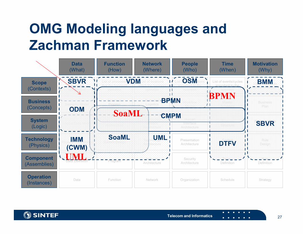
OMG Modeling languages andZachman Framework
27
Data(What)
Function(How)
Network(Where)
People(Who)
Time(When)
Motivation(Why)
Scope(Contexts)
Business(Concepts)
System(Logic)
Technology(Physics)
Component(Assemblies)
List of thingsimportant
to business
List of processesthat the business
performs
List of locationswhich the business
operates
List of organizationsimportant to the
business
List of events/cyclesimportant to the
business
List of businessgoals/strategies
Semantic ModelBusinessProcessModel
BusinessLogisticsSystem
WorkflowModel
MasterSchedule
BusinessPlan
Logical Data Model ApplicationArchitecture
DistributedSystem
Architecture
HumanInterface
Architecture
ProcessStructure
Business RuleModel
Physical Data Model System Design TechnologyArchitecture
PresentationArchitecture
ControlStructure
RuleDesign
Data Definition Program NetworkArchitecture
SecurityArchitecture
TimingDefinition
RuleDefinition
Operation(Instances)
Data Function Network Organization Schedule Strategy
BMM
SBVR
VDM OSMSBVR
DTFV
BPMN
UMLIMM(CWM)
CMPM
SoaML
ODM
UML
SoaML
BPMN

Telecom and Informatics
Context and Goals
Interactions
Interface
Channels
Roles
Actors
Resources
Functions
Tasks
Executors
Processes
Orchestra-tion
Workflows
Information
Data
Stores andMessages
EFAExtra
FunctionalAspects
QoSSLA
Monitoring,adaptation
Inte
ract
ion
Requirements
Func
tion
Coo
rdin
atio
n
Info
rmat
ion
Qua
lity
Design
Implementation
Infrastructure
Stru
ctur
e
RoleModels
UMLClass
Ontologies
Goal orientedUse cases/stories
UIIFMLWebML
OCL
collaboration
withINF5120Modelinglanguages
Model Driven Architecture/MDE
SoaML BPMN

Telecom and Informatics 29
PIM-K
CIM-KOntologies Bus.Process Bus.Rules Goals NFA/Qualities Org
BPDM, SBVR,EDOC,UPMS,
PIM4SOA, ODM
PSM-K
BPMN, POP*, ARIS,ArchiMate,
GERAM, GRAI, Zachman,UEML, B.Rules. ..
Technologies/Realisation-K
UML profiles andmetamodels forBPEL, WSDL, XML,
XPDL,OWL-S, WSML, WSDL-S
TechnologyReliastion
Code
Information Process Services Rules NFA UI
Data Wflow/Comp Interfaces Rules NFA UI
XML, BPEL/XPDL, WSDL, SWRL, Security, AJAXOWL, OWL-S/WSML WSDL-S, Induction, … QoS
Legacy and New systems/services, ERPs/ESAs

Telecom and Informatics
Information modeling and OntologyEngineering – Semantic technologiesn Conceptual Modeling – ISO TR 9001n ER Modeling, NIAM Modeling, EXPRESS Modelingn UML Modelingn ISO 19103 – Conceptual Schema with UMLn Semantic Web Modelingn Ontology Engineeringn Logic Formalisms – First order logicn XML Schema, RDF, Topic Maps, OWLn ODM - Ontology Definition Metamodeln Open Linked Data, Open Linked Services
30

Telecom and Informatics 31
Conceptual Modeling
n Conceptsn Conceptual modeln Conceptual schema languagen Conceptual schema
n Why conceptual modeling in 19100?n to provide a rigorous definition of geographic information and
geographic information servicesn to standardize the definition of conceptual schemas

Telecom and Informatics 32
Real World
Conceptualformalism
Conceptual Schema Language(s)
Lexical Languages
Graphical Languages
basis for one or more
ConceptualModel
Universe ofDiscourse
defined in
Conceptual Schema
formally represented in
provides formallanguage forrepresenting
provides conceptsfor describing
From reality to conceptual schema

Telecom and Informatics 33
ConceptualModel
Universe ofDiscourse
ISO 100% Principle- static aspects- dynamic aspects
InformationSystem
Real World- Problem
domain
Solutiondomain
Basis for
Information modeling Data modeling
1) 2) Conceptualisation principle- exclude physical representation
3) Helsinki principle- agree set of rules
4) Concrete syntax- UML
5) Self description
Principles

Telecom and Informatics 34
ConceptualModel
Universe ofDiscourse
ISO 100% Principle- static aspects- dynamic aspects
InformationSystem
Real World- Problem
domain
Solutiondomain
Basis for
Information modeling Data modeling
What is relevant ?Information,
Rules, constraintsBehaviour/Dynamics – services, process

Telecom and Informatics 35
Different kind of models
n Conceptual models
n Specification models
n Implementation models

Telecom and Informatics 36
PurchaseProcess2
OrderInfo :OrderInfo
ProceedPurchase2
Handle invoice2
Order Process2
confInfo
DeliveryProcess2
invoiceInfo
Seller2 : ISellerCustomer2 : ICustomer
Activity model
Information model
Interaction model
UML Activity model (or BPMN)
UML component diagram(enhanced in UML 2.0), SoaML
UML Class diagram
LTB HPL
ICustomer ISeller
IProdOwn
LHH
IWareHouse
TRA
ITransportServ
OrderLine+ nrOfProd : Int
<<entity>>
Invoice- date : Date- amount : Currency
<<entity>>
SellerEntity- name : String
<<entity>>
Product+ prodNr : Int+ descript ion : String
<<entity>>
Shipment+ delivAddress : Address
<<entity>>
CustomerEntity+ name : String+ address : String+ phonenr : String
<<enti ty>>
PurchaseOrder- poNr : int- date : Date
<<entity>>
Order+ orderNr : Int+ date : Date
<<entity>>
1. .*1. .*
Informationmodeling
SemanticModels

Telecom and Informatics
Parts of UMLMetamodel
ClassAttribute
initialValue : Expression
DataTypeOperation
SpecificationisPolymorphic : Booleanconcurrency : CallConcurrencyKind
GeneralizableElement
Feature
BehaviouralFeatureStructuralFeature
Association
Classifier
0..*
+features
0..*
AssociationEnd2..n2..n
0..*0..*
0..* 1
0..*
1
0..*
0..*

Telecom and Informatics
Different kind of models
Idea Systemguide thethoughtprocess
semantics,algorithms,datastructures,performancemeasures, ...
focus onsemanticintent

Telecom and Informatics
Information Modeling Guidelines
n Process steps
n Modeling phases
n Modeling harmonization

Telecom and Informatics
Process Steps
n A) Problem definition - Enterprise (Analysis)n 1) Identify Area of Concern/Problem definitionn 2) Goals (Use cases)n 3) Interaction scenarios (sequence / collaboration diagrams)n 4) High level domain model / concepts (Class diagrams)
n B) Domain model - Informationn C) Architectural Model - Servicesn D) Implementation modelsn E) Implementationn F) Maintenance

Telecom and Informatics
Phase 0: Identify scope and context
Phase 1: Identify basic entities
Phase 1b: Is the modeling approach consistentwith the approach described in the rules forapplication schema document
Phase 2: Specify relationships, attributes andpossibly operations
Phase 3: Completion of constraints
Phase 4: Model definition harmonisation –withsub-models and other work items
Information Modeling

Telecom and Informatics
P1 Identify basic entities
n Refine objects/classes from enterprise viewpointn Tasks
n 1) Identify generic and specific conceptsn 2) describe each of the entititesn 3) Watch out for synonyms and homonymsn 4) Create a data dictionary (glossary of terms)
n Questionsn Are entities according to scope?n Can we categorize entities?’n What are the attributes and constraints?
n 1b) Consistent with rules for application schemas?

Telecom and Informatics
P2 Specify relationships, attributesand operationsn The entities of interest -
corresponding to units ofinformation
n Any generalizationrelationships betweenentitites
n Other relationships betweenentities
n Check if the existence of anentity depends on theexistence of another entity
n What consistency rules need tobe satisfied in order for aninstance of the entity, or modelas a whole, to be valid.
n The semantics, if any, of thetypes used for attributes
n Which attributes uniquely identifyan entity
n The attributes of the entities andwhether any of them can bederived from other attributes
n Homonyms and synonyms -create a glossary of terms

Telecom and Informatics
Checklist
1) Readability2) Scope3) nym principle4) context independence5) implementation independence6) invariance7) constraints8) reality9) redundancy10) concepts11) hierarchies12) simple types
Checklist
1) Readability2) Scope3) nym principle4) context independence5) implementation independence6) invariance7) constraints8) reality9) redundancy10) concepts11) hierarchies12) simple types
Before harmonization
n Review your work criticallyn RATIONALIZE
n Remove redundancy:n Ensure that each relationship
is only specified once.n Ensure that each constraint
is captured only once, andthat multiple constraints areseparated.
n Ensure that if one entity isdependent on another, thenthe relationship is specifiedfrom the dependent to theindependent.

Telecom and Informatics
Model harmonization
n Are there redundancies or conflicts?
n Are there any ambiguities?
n Are the models complete?
n Do the abstraction levels match?

Telecom and Informatics
More semantics using ontologies
n Models can be annotatedn Creating a connection between the models and a formal ontology
n The annotations can be used in order to ”automate”mapping definitionsn Not complete automationn Can be used for aiding mapping designer through tool support
n The reasoning power from the world of ontologies comesinto play heren Query the ontology system for things like
n ”Give me a list of elements in Model B that are annotated with similarontology concepts as element X in Model A”

Telecom and Informatics
Ontologies
n Ontologies provide a shared understanding of a domainn They provide background knowledge to systems to automatize certain
tasksn By the process of annotation, knowledge can be linked to ontologies
n Example: “Angelina Jolie” (Text) linked to concept Actressn In our ontology we also know that an actress always is female and a
personn Ontologies allow the creation of annotations à machine-readable and
machine-understandable contentn If machines can understand content, they can also perform more
meaningful and intelligent queriesn Distinction of Jaguar the animal and the carn Combination of information that is distributed on the Web
47

Telecom and Informatics
Definitions
n An ontology defines the basic terms and relations comprising thevocabulary of a topic area, as well as the rules for combining termsand relations to define extensions to the vocabulary
n An ontology is a hierarchically structured set of terms for describing adomain that can be used as a skeletal foundation for a knowledgebase
n An ontology provides the means for describing explicitly theconceptualization behind the knowledge represented in a knowledgebase
n An ontology is a formal, explicit specification of a sharedconceptualization

Telecom and Informatics
Examples
49

Telecom and Informatics
Features of an ontology
n Modelled knowledge about a specific domainn Defines
n A common vocabularyn The meaning of termsn How terms are interrelated
n Consists ofn Conceptualization and implementation
n Containsn Ontological primitives
50

Telecom and Informatics
Catalog/ID
Thessauri“narrower term”
relationFormal
is-aFrames
(properties)
GeneralLogical
constraints
Terms/glossary
Informalis-a
Formalinstance
ValueRestrs.
Disjointness,Inverse, part-Of ...
Classifications of ontologies
51
Lassila O, McGuiness D. The Role of Frame-Based Representation on the Semantic Web.Technical Report. Knowledge Systems Laboratory. Stanford University. KSL-01-02. 2001.

Telecom and Informatics
Languages for building ontologies
n Ontologies can be built using various languages with variousdegrees of formalityn Natural languagen UMLn ERn OWL/RDFSn WSMLn FOLn ...
n The formalism and the language limit the kind of knowledgethat can be represented
n A domain model is not necessarily a formal ontology onlybecause it is written in OWL
52

Telecom and Informatics
Applications of ontologies
n Knowledge representationn Ontology models domain knowledge
n Semantic annotationn Ontology is used as a vocabulary, classification or indexing
schema for a collection of itemsn Semantic search
n Ontology is used as a query vocabulary or for query rewritingpurposes
n Configurationn Ontology defines correct configuration templates
53

Telecom and Informatics
Principles for the design of ontologies
n Clarityn To communicate the intended meaning of defined terms
n Coherencen To sanction inferences that are consistent with definitions
n Extendibilityn To anticipate the use of the shared vocabulary
n Minimal Encoding Biasn To be independent of the symbolic level
n Minimal Ontological Commitmentsn To make as few claims as possible about the world
54
Gruber, T.; Towards Principles for the Design of Ontologies.KSL-93-04. Knowledge Systems Laboratory. Stanford University. 1993

Telecom and Informatics
Ontology engineeringn The set of activities that concern the ontology development process,
the ontology life cycle, and the methodologies, tools and languages forbuilding ontologies
n Ontology life cycle
55
Domain analysismotivating scenarios, competency questions, existing solutions
Conceptualizationconceptualization of the model, integration and extension of
existing solutions
Implementationimplementation of the formal model in a representation language
Usage/Maintenanceadaptation of the ontology according to new requirements
Know
ledge acquisition
Evaluation
Docum
entation
Project management: controlling, planing, quality assurance etc.

Telecom and Informatics
Ontology engineering activitiesManagement SupportDevelopment oriented

Telecom and Informatics
Methodologies for building ontologies
n Validated guidelines on how the ontology building processshould be structured
n Well-organized process instead of „ontology developmentdriven by inspiration and intuition only“
n Methodologies do not support all of the aforementionedactivities
n They implicitly assume a particular development paradigmfor the ontology engineering process
n Some of them also provide supporting methods and toolsn There are many different methodologies for building
ontologies
57

Telecom and Informatics
How to build an ontology?Natalya F. Noy and Deborah L. McGuinness. ̀ `Ontology Development 101: A Guide to Creating Your First Ontology''. Stanford Knowledge SystemsLaboratory Technical Report KSL-01-05 and Stanford Medical Informatics Technical Report SMI-2001-0880, March 2001.
n Step 1: Determine the domain and scope of the ontologyn What is the domain that the ontology will cover?n For what we are going to use the ontology?n For what types of questions the information in the ontology should
provide answers?n Who will use and maintain the ontology?
n Competency Questionsn A set of queries which place demands on the underlying ontologyn Ontology must be able to represent the questions using its
terminology and the answers based on the axiomsn Ideally, in a staged manner, where consequent questions require
the input from the preceeding onesn A rationale for each competency question should be given
58

Telecom and Informatics
How to build an ontology? (cont’)Natalya F. Noy and Deborah L. McGuinness. ̀ `Ontology Development 101: A Guide to Creating Your First Ontology''. Stanford Knowledge SystemsLaboratory Technical Report KSL-01-05 and Stanford Medical Informatics Technical Report SMI-2001-0880, March 2001.
n Step 2: Consider reusing existing ontologiesn Reuse ensures interoperability and reduces costsn Ontology libraries and tools for customization are required for this stepn Sub-steps
n Discover potential reuse candidatesn Evaluate their usabilityn Customize ontologies to be reusedn Integrate and merge to the target ontology
n Step 3: Enumerate important terms in the ontologyn What are the terms we would like to talk about?n What properties do those terms have?n What would we like to say about those terms?
59

Telecom and Informatics
How to build an ontology? (cont’)Natalya F. Noy and Deborah L. McGuinness. ̀ `Ontology Development 101: A Guide to Creating Your First Ontology''. Stanford Knowledge SystemsLaboratory Technical Report KSL-01-05 and Stanford Medical Informatics Technical Report SMI-2001-0880, March 2001.
n Step 4: Define classes and class hierarchyn From the list created in Step 3, select the terms that describe objects
having independent existence rather than terms that describe theseobjectsn These terms will be classes in the ontology
n Organize the classes into a hierarchical taxonomy by asking if by being aninstance of one class, the object will necessarily (i.e., by definition) be aninstance of some other classn If a class A is a superclass of class B, then every instance of B is also
an instance of An Classes as unary predicates—questions that have one argument. For
example, “Is this object a wine?”n Later: binary predicates (or slots)—questions that have two
arguments. For example, “Is the flavor of this object strong?” “What isthe flavor of this object?”
60

Telecom and Informatics
How to build an ontology? (cont’)Natalya F. Noy and Deborah L. McGuinness. ̀ `Ontology Development 101: A Guide to Creating Your First Ontology''. Stanford Knowledge SystemsLaboratory Technical Report KSL-01-05 and Stanford Medical Informatics Technical Report SMI-2001-0880, March 2001.
n Step 5: Define attributes and relationshipsn Step 4 selected classes from the list of terms we created in Step 3
n Most of the remaining terms are likely to be properties of theseclasses
n For each property in the list, we must determine which class itdescribes
n Types of propertiesn “intrinsic” propertiesn “extrinsic” propertiesn parts, if the object is structured (physical or abstract)n relationships to other individuals
n Properties are inherited and should be attached to the most general classin the hierarchy
61

Telecom and Informatics 62
MagicDraw – Models with code generation sets

Telecom and Informatics
UML models
63

Telecom and Informatics
Quick guided tour of the language
nGeneral mechanismsn Packagesn Classes
n UML profilesn Stereotypesn Tagged valuesn Notesn Constraints
n Basic diagramsn Class diagramsn Object diagramsn Use case diagramsn Sequence diagramsn Collaboration diagramsn Statechart diagramsn Activity diagramsn Component diagramsn Deployment diagrams
64

Telecom and Informatics
UML Information Modeling
n Ref also ISO 19103 Standard for Conceptual Modeling
n The following material is for reference …..
65

Telecom and Informatics
Packages
nModelsstructuring
66

Telecom and Informatics
Class diagrams
n Class diagrams represent a set of classes, interfacescollaborations, and their relationships.
n They are the most frequent diagrams in the objectssystems modeling.
n They offer the static conceptual view of a system.n Class diagrams, (including active classes), offer the static
process view of a system.
67
Zebra<<interface>>
Zebu

Telecom and Informatics
Classes
n A class is an abstract descriptionof set of objects
n A class can be seen as afactorization of commonelements to a set of objects
n A class describes the definitiondomain of a set of objects
n Description conceptually split intwo partsn A class specification which defines
the definition domain and theproperties of the class instances(datatype)
n A realization defines how aspecification is realized
n Classes featuresn Attributesn Operationsn Réceptionsn Relationsn Multiplicityn Persistencen Component
68

Telecom and Informatics
Objects
Can represents
n One instance
n One type, interface
n One class
Ola :Person
Person
<<Interface>>Person
Objekt modellering

Telecom and Informatics
Object and classes- notation
Person
navn : stringpersonnr. : integeradresse : stringgasje : moneystillingstittel : string
endre-stilling()endre-adresse()
Example - object class
Objekt modellering

Telecom and Informatics
Objektklasser -notasjon
Klassenavn
attributtnavn-1 : datatype-1 = defaultverdi-1attributtnavn-2 : datatype-2 = defaultverdi-2
operasjonsnavn-1 (argumentliste-1) : resultattype-1operasjonsnavn-2 (argumentliste-2) : resultattype-2
. . . .
. . . .
Objekt modellering

Telecom and Informatics
GM_Primitive
+ boundary() : Set(GM_Primitive)
(from GeomPrimitive) GM_Complex(from GeomComplex)
GM_Object+ mbRegion : GM_Object+ representativePoint : DirectPosition
+ SRS() : SpatialReferenceSystem+ transform(SRS : SpatialReferenceSystem) : GM_Object+ equals(object : GM_Object) : Boolean+ distance(object : GM_Object) : Distance+ dimension() : Integer+ dimension(point : DirectPosition) : Integer+ coordinateDimension() : Integer+ envelope() : Envelop+ boundary() : Set(GM_Object)+ buffer(radius : Distance) : GM_Object+ convexHull() : GM_Object+ centroid() : DirectPosition+ representativePoint() : GM_Point+ isInComplexes() : Set(GM_Complex)+ isPartOf(geomCplx : GM_Complex) : Boolean+ universe() : GM_Complex
SpatialReferenceSystem(from DirectPositioningSchema)
1
+srs
1
Class diagram

Telecom and Informatics
Class attributes
ClassName
/ /* derived attribute
+ /* public visibility# /* protected visibility- /* private visibilityunderline /* class scope

Telecom and Informatics
[visibility] name [multiplicity] [:type] [= initial value] [{property-string}]
+ origin [0..1] : Point = (0,0) {frozen}
defined properties: changeable, addOnly, frozen (const)
Class attributes

Telecom and Informatics
Attributes and data types
n A data type specifies a legal value domain andthe operations on values of that domain
n Four categoriesn a) Basic data types (integer, real, string, …)n b) Collection data types (from OCL)n c) Enumerated data types (user-definable finite sets)n d) Model types

Telecom and Informatics
Operations
An operation is a specification of• a transformation, or• a query
A method is a procedure thatimplements an operation.

Telecom and Informatics
Operations
[visibility] name [(parameter-list)] [:return-type] [{property-string}]
[(parameter-list element)] ::=[direction] name : type [= default-value]
[direction] ::= in | out | inout
+ set ( in name : Name, in place : String = ‘Oslo’): Boolean {concurrency=sequential}
defined properties: isQuery, concurrency, ...

Telecom and Informatics
Class diagrams
78
parameter
parameterized class
a class another classassociation name
associationclass nameattributesoperations
a class another classassociation name
/ derived association
role r1 role 2
class name
attributesattr_name : type = initial value
operationsop_name (arg_list):type
class name
- private attribute+ public attribute# protected attribute
- private operation+ public operation# protected operation

Telecom and Informatics
Properties visibility
n Public +Accessible to all object within the
systemn Protected #
Accessible to instances ofimplementing class and itssubclasses
n Private -Accessible to instances of the
implementing classn Underlined
Class variable/operation
79
+public_operation()#protected_operation()-private_operation()
+public_attribute#protected_attribute
-private_attribute
Thing

Telecom and Informatics
Relations between classes
n Associationn Aggregationn CompositionnGeneralizationn Dependency
n An associationexpresses a bi-directional semanticconnection betweenclasses
n An association is anabstraction of the linksexisting between theinstances objects ofthe associated classes
80

Telecom and Informatics
Optional/Conditional
n In UML all attributes and operations are perdefault mandatory.
n Optional data values for attributes can beshown through multiplicity [0..1].
n Conditional should relate to a note withconstraint expressed in text/OCL (ISO19103)

Telecom and Informatics
Relationships
Association (the “glue”)A semantic relationship between elements(involves connections among their instances)
Generalization (inheritance)A relationship between an elementand the sub-elements that may be substitutedfor it
DependencyThe use of one element by another
Refinement/realisationA shift in levels of abstraction

Telecom and Informatics
Purpose: To show relationships between model entitiesTo define multi-way constraints
AssociationNameRoleNameRoleName
1..*2
Multiplicity ofan Association
Dependency (Client-Server) Composition (Strong Aggregation)
Generalization Aggregation
Link AttributeAssociation Notationused to “anchor” at noteto a model entity
Different relationships in UML Diagrams

Telecom and Informatics
Generalisation and Association
WomanMarried with
0..1 0..1
Person Bookloans
Loancustomer
Loan-entity
0..1 0..*
Man
{not siblings}
Generalisation
Superclass
Subclasses (inherits attributes and operations)
wifehusband
Arrow can be used toshow direction ofknowledge
Association

Telecom and Informatics
Example
85
Telecom and Informatics
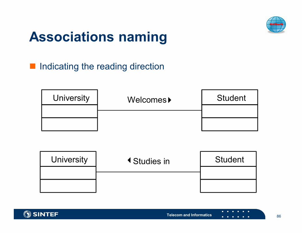
Associations naming
n Indicating the reading direction
86
University StudentWelcomes
University StudentStudies in

Telecom and Informatics
Roles naming
n A role describes an association end
87
University Person+Student
+Employer +Teacher

Telecom and Informatics
Roles multiplicity
88
1 One only0..1 Zero or oneM .. N From M to N (natural numbers)* Several0 .. * Zero to several1 .. * One to several

Telecom and Informatics
Roles visibility
n Publicn Protectedn Private
89
A
B
+Public role
*
-Private role
*
C
*
#Protected role
*

Telecom and Informatics
Navigability
n given an unlabelled associationbetween two classes, it ispossible to navigate from objectsof one kind to objects of the otherkind.
n by default an association is bi-directional.
n a navigability indication suggeststhat an object at one end isdirectly and easily reachable froman object at the other end.
n putting it into practice, forinstance a source objectmemorizes a direct reference tothe target objects.
n Given a user, it is desirable to haveaccess to his / her passwords
n Given a password, it is not desirableto have access to the correspondinguser
90

Telecom and Informatics
Example
91

Telecom and Informatics
Aggregation
n Antisymmetric bi-directional semantic connectionsn An association expressing a stronger coupling between
classesn Relationship representation
n master and slaven whole and partsn composed and composing
92

Telecom and Informatics
Composition
n Physical compositionmodelingn Maximum multiplicity of
1 on the aggregate siden Automatic propagation
of the destruction
93
Aggregate Part
1 *

Telecom and Informatics
Classes hierarchy
nManaging thecomplexityn Class tree of increasing
abstraction
94
Sub-class
Super-class
More generalclass
More specificclass

Telecom and Informatics
Multippel arving - eksempel
Ansatt
Selger Sjef
DirektørSalgssjef
{overlapping}
Objekt modellering

Telecom and Informatics
Multiplicity constraints
Multiplicity shows how many instances of a class that canbe related to one instance of the class at the other end ofthe association
Class
Class
Class
Class
Class
0..*
1
0..1Class*
1..*
3,5,10

Telecom and Informatics
Aggregation
Loose (weak) part-of relationship
Phonebook Subscription
0..* *
Open diamond
Multiplicity > 1 possibleExists even if a phone bookgoes away
listedIn subscriptions
associationrole names

Telecom and Informatics
Composition(“strong aggregation”)
Strong part-of relationship
File Recordcontains1 *
Filled diamond
Multiplicity max 1 Existence dependent

Telecom and Informatics
Associations
Fig. 3-31, UML Notation Guide
Person
Manages
JobCompany
boss
worker
employeeemployer1..*
*
*
0..1
Job
Account
Person
Corporation
{Xor}
salary

Telecom and Informatics
Association Ends
Fig. 3-32, UML Notation Guide
Polygon PointContains
{ordered}
3..*1
GraphicsBundle
colortexturedensity
1
1
-bundle
+points

Telecom and Informatics
Association class
Are used instead of link-attributes ifnThe association are related to other objectsnOperations are attached to the association
Person BookLoans
Loan dateDelivery data
Loan
CheckDate()Expired loans
1 1..*
*

Telecom and Informatics
Constraints on relationships
Portfolio
BankAccount
{secure}
Persont
Corporation
{or}
Department
Person
member manager
{subset}
* *
1..* 1

Telecom and Informatics
Geometry Package(from Logical View)+ Accuracy+ TopologicalGeometry+ RepresentationalGeometry+ TemporalGeometry+ Geometry+ Vector{dimension}+ SpatialVector
Packages in UML
n This is a grouping of modelelements and diagrams.
n Package dependencies usuallysummarize dependencies amongthe contents of the packages.
n Packages can contain otherPackages.
n Packages can show theClass/Entities found in a givenPackage.

Telecom and Informatics
Containment and dependency
Foundation
ModelManagement
BehavioralElements
CoreExtensionMechanisms
DataTypes

Telecom and Informatics
Commentsandconstraints
<<requirement>>Shall conform to ….
Notes:
Common Mechanisms
n Adornments: notesn Extensibility mechanisms: stereotypes,
tagged values, constraints

Telecom and Informatics
Stereotypes
n Used to define derivative modeling conceptsbased on existing generic modelingconcepts
n Defined by:n base (meta-)class = UML meta-class or
stereotypen constraintsn required tags (0..*)
n often used for modeling pseudo-attributesn icon
n A model element can have at most onestereotype

Telecom and Informatics
Tagged values - properties
Name (tag) separator (=) value (of the tag)
properties on an element - relevant for code generation orconfiguration management (Can be applied to all UML elements)
Server{processors = 3}
Billing{version=3.2status=checkedOutby=ajb}

Telecom and Informatics
OCL - Object Constraint Language
First order predicate logic, for Boolean expressions - included in UML 1.1
Can be used for:invariants,value restrictions,pre- and postconditions
Personself.age > 0
Married people are of age >= 18self.wife->notEmpty implies self.wife.age >= 18 andself.husband->notEmpty implies self.husband.age >= 18 and
Expressions with:and, or, not, implies, exists, for all,Collections (select, reject, collect, iterate)

Telecom and Informatics
UML profiles
109

Telecom and Informatics 110
UML profiles
n They allow us to adapt the UML language to the needs ofthe analysts or the application domain
n Allows designers to model using application domainconcepts.
n There are three extension mechanisms:n Stereotypesn Tagged valuesn Constraints

Telecom and Informatics
UML for a specific purpose (benefits)= a specific profilen Profiles exist for :
n technical targets (C++, RDB, Java, CORBA, XML, Real Time, etc.)n specific disciplines (Analysis, Design, etc.)n requirement analysisn tests (test for Java, test for EJB, test for C++, etc.)n metrics, quality checking, and profiles for managing configuration
management rules.n From early requirement down to final tests, UML profiles
can drive each specific discipline involved.
111

Telecom and Informatics 112
Stereotype
n Extends the vocabulary of UML with new construction elementsderived from existing UML but specific to a problem domain
n Can have associated tagged values and constraintsn Possibility of assigning an icon for a better graphical representation
DB Partners

Telecom and Informatics
Examples of other stereotypes

Telecom and Informatics 114
Tagged value
n Is a property associated to a model elementn Used to store information about the element
n Management information, documentation, coding parameters, ...n Generally, the tools store this information but it is not shown in the
diagrams

Telecom and Informatics
Constraints
n Any semantic relationship between model elementsn Expressed in OCL (Object Constraint Language) or in
natural languagen {constraint}, inv, pre-, post-condition
115

Telecom and Informatics
Profile: Example (Usage of UMLextensions)n Below is a user model example, with extensions. That example
supports extensions.n We will see how they are defined at the profile definition level.
116
<<persistent>>Customer
{storageMode = hash}
<<identifier>> number : int
Stereotype
Tagged Value
ClassAttribute
PROFILE
UML
EditCheckGenerate SQL…
Operation

Telecom and Informatics
Extending Metaclasses
n A profile consists primarily of stereotypesn restricted metaclasses that can only be used to extend existing
metaclasses
117
«profile» EJB
«metaclass»Component
«stereotype»Bean
{required}
«stereotype»Session
«stereotype»Entity
state: StateKind
«enumeration»StateKind
statelessstateful

Telecom and Informatics
Applying a Profile
118
«profile» EJB
«metaclass»Component
«stereotype»Bean
{required}
«stereotype»Session
«stereotype»Entity
state: StateKind
«enumeration»StateKind
statelessstateful
UserModel
«apply»
«session»Customer
name: String
state=stateless
Applying a profile makes the profile extension available to themodel packages to which it is applied.

Telecom and Informatics
Implementation neutral! Not implementation specific!
ISO 19103 – Conceptual modeling with UML- a UML profile for Information modeling
n Basic data typesn Stereotypesn Namingn Documentation of modelsn Information modelling guidelines

Telecom and Informatics
Basic Types
n Primitiven Decimal, Integer, Number, Real, Vector, Character,
CharacterString, Date, Time DateTime, Binaryn Sign, Boolean, Logical, Probability
n Collectionsn Set<T>, Bag<T>, Sequence<T>, Dictionary<K,T>
n Measuresn Angle, Area, Distance, length, Scale, MTime, Velocity, Volume,
UnitOfMeasuren Records, Namespace

Telecom and Informatics
Number
Number<<BasicType>>
Integer<<BasicType>>
Real<<BasicType>>

Telecom and Informatics
Sign+ positive+ negative
<<Enumeration>>
MD_Restrictions1+ copyright = 1+ patent = 2+ patentPending = 3+ trademark = 4+ licence = 5+ intellectualPropertyRights = 6+ restricted = 7+ otherRestric tions = 8
<<CodeL ist>>
1 copyr ight2 patent3 patentPending4 trademark5 licence6 intel lectualProperty Rights7 res tricted8 otherRestr ict ions
MD_Restrictions2<<CodeList>>
DirectPosition+ coordinate : Sequence<Num ber>/+ dim ension : Int eger
<<DataType>>
GM_Posit ion+ di rect : DirectPosition+ indirect : GM_PointRef
<<Union>>
User defined data types
n <<DataType>>
n <<Enumeration>>
n <<CodeList>>
n <<Union>>

Telecom and Informatics
Class Stereotypes
n NONE
n <<Interface>>
n <<Type>>
n <<Abstract>>
n <<MetaClass>>
GM_GenericCurve
+ startPoint() : DirectPosition+ endPoint() : DirectPosition+ param(s : Distance) : DirectPosition+ tangent(s : Distance) : Vector+ ...()
<<Int erface>>
GM_LineString+ controlPoint : GM_PointArray
+ GM_LineString(points[2..*] : GM_Position) : GM_LineString+ asGM_LineSegment() : Sequence<GM_LineSegment>
GM_Curve<<Type>>
GM_CurveSegment+ interpoilation : GM_CurveInterpolation = "linear"+ numDerivatesAtStart[0,1] : Integer = 0+ numDerivatesAtEnd[0,1] : Integer = 0+ numDerivateInterior[0,1] : Integer = 0
+ samplePoint() : GM_PointArray+ boundary() : GM_CurveBoundary+ reverse() : GM_CurveSegment
<<Abstract>>
0..1 1..*
+curve
0..1
+segment
1..*Segmentation

Telecom and Informatics
GM_CurveSegmentMD_CitationGM_FeatureAttribute
Class (package, association) names
n All classes must have unique names.n Names shall start with upper case letter.n Should not have a name that is based on its
external usage, since this may limit reuse.n Should not contain spaces
n Separate words in a class should be concatenated, e.g.“XnnnYmmmm”
n Class names should start with bialpha prefixes foreach standard part.

Telecom and Informatics
computePartialDerivatescompute Partial Derivatescompute_partial_derivatives
Attribute, operation and role names
n Shall start with lower case lettern Concatenate words shall begin with capital lettern Do not repeat class names in attribute namesn Keep names technical, meaningful and short, if possible

Telecom and Informatics
GM_Curve<<Type>>
GM_CurveSegment<<Abstract>>
1..*0..1
+segment
1..*
+curve
0..1
Segmentation
Associations
n Multiplicity shall be defined for both associations endsn All associations ends (roles) representing the direction
of a relationship must be named or else the associationitself must be named
n The role name must be unique within the context of aclass and its supertypes.
n The direction of an association must be specified

Telecom and Informatics
NB! Font size > 8pt
GM _Curve<<T ype>>
Documentation of modelsn Diagrams
n Package dependency diagramsn Class diagramsn Class context diagrams
n Textn Class
n General description, semantics,supertypes/subtypes
n Attributes, Associationsn Operations
n preconditions, input/output parameters, return value,post conditions, exceptions, constraints
n Constraints