inertial thigh angle sensing for a semi-active knee prosthesis
TRANSCRIPT

INERTIAL THIGH ANGLE SENSING FOR A SEMI-ACTIVE KNEEPROSTHESIS
George Thomas and Daniel Simon∗ †
Department of Electrical and Computer EngineeringCleveland State University2121 Euclid Ave, 44115Cleveland, Ohio, USA
∗[email protected] and†[email protected]
ABSTRACTWe present an application of a microelectromechanical sys-tems (MEMS)-based inertial measurement unit (IMU) tothigh angle estimation for the control of a semi-active kneeprosthesis. By using inertial based measurement devices,we can move all of our sensors to one location inside theprosthetic leg. These sensors are challenging to use, how-ever, because error in their measurements will accumulateover time. We show that by applying the Kalman filter to anIMU consisting of a dual-axis accelerometer and a single-axis gyroscope, we can decrease the integral of squared er-ror of our thigh angle estimates by 70%.
KEY WORDSKalman filter, MEMS, IMU, Prosthetics, Sensors
1 Introduction
The field of prosthetics is significant, because prosthesescan allow amputees to perform many of the tasks that non-amputees can. However, the use of traditional leg prosthe-ses for above knee amputees can cause accumulative, de-generative effects, such as stump tissue damage [1], backpain, joint cartilage damage, and osteoarthritis [2]. Tradi-tional leg prostheses are passive, and so the wearer mustsupply abnormal forces and torques to walk. We can at-tribute the degenerative effects to joint pressures causedby these abnormal forces [1]. Thus, it would be usefulto have active prostheses, which can generate forces to re-store normal gait in patients, but the necessary motors andpower supplies usually make fully active prostheses infea-sible. However, semi-active prostheses can perform bet-ter than passive prostheses without requiring massive ac-tive components, and by intelligently storing and releasingenergy [3]. These attractive properties motivate our workon the control of semi-active knee prostheses.
Because the failure of a prosthesis may cause signif-icant harm to its user by causing him to fall, the controlsystems in active or semi-active prostheses must be ro-bust. In previous work, we have developed an artificial neu-ral network (ANN) based closed-loop control for the knee
∗Corresponding author
joint actuator of a semi-active, above-knee prosthesis [4].Closed-loop control is more robust than open-loop control,because the use of feedback in closed-loop control reducesthe control system’s sensitivity to disturbances and randomvariations in system parameters [5].
We determined that during the stance phase of gait forthe prosthesis, the thigh angle of the prosthetic leg stronglydepends on the operation of the knee. However, duringswing phase, the user’s thigh angle does not depend on theaction of the prosthesis. Instead, the state of the prosthe-sis depends on the thigh angle, which the user fully con-trols. [4]. For example, during stance phase, if the kneejoint of the prosthesis does not produce torque while theuser puts his weight on it, the knee will quickly bend. Theuser will then begin to fall and must adjust his thigh angleabnormally to keep his torso upright. It is undesirable fora prosthetic leg to require its user to adjust his thigh angleabnormally.
We have chosen to use thigh angle as a control inputfor our stance phase ANN but not for our swing phase ANNbecause the thigh angle is partially determined by the kneeparameters during stance phase, and because we use oneANN for swing phase control and another, separate ANNfor stance phase control. Finally, because we want to usethe thigh angle for closed-loop control, we must be ableto sense it; this need for a thigh angle sensor is what hasmotivated our work on this subject.
The use of thigh angle as an input in our closed-loopcontrol presents a problem in the physical implementationof our prosthesis, because conventional angle sensors basedon rotary encoders or hall-effect sensors need to be locatedclose to the axis or point of rotation. This is not a possibil-ity for our application, because it would mean that the userof the prosthesis must wear an external thigh angle sensor.The most preferable angle sensor would be located some-where within the prosthesis so that it would not be invasiveto the wearer.
We propose the use of a MEMS based IMU as analternative to traditional angle sensors. IMUs have seenextensive use in navigation applications [6], but have onlyrecently found applications in prosthetics [7]. When werefer to an IMU, we imply a device with one or more ac-celerometers and one or more gyroscopes. This is because
Proceedings of the IASTED International SymposiaImaging and Signal Processing in Health Care and Technology (ISPHT 2012)May 14 - 16, 2012 Baltimore, USA
DOI: 10.2316/P.2012.771-028 119
IMUs are much more expensive than traditional angle sen-sors, and location constraints usually do not prohibit theuse of traditional sensors.
There have been several publications about the appli-cation of IMUs to joint angle sensing, but few in the con-text of prosthetics. In [8], an IMU based knee angle sensorcomposed of two dual-axis accelerometers and two single-axis gyroscopes was presented. Geometric methods wereused to extract knee angle data from the sensors. Also,in [9], one dual-axis accelerometer and a single-axis gyro-scope were used to sense knee angle. The knee angle wascomputed by integrating gyroscope data and the accelerom-eter was used to calibrate the gyroscope under static condi-tions. The Kalman filter has also been used to compute theinclination of various body parts, using three single-axisgyroscopes and three single-axis accelerometers arrangedin a box [10].
The small size and simplicity of use of MEMS-basedIMUs make them suitable for our application; however,IMUs alone provide poor attitude estimates. Simply inte-grating the angular rate information from an IMU will pro-duce a signal that drifts, as a gyroscope signal will oftennot be zero-mean. The direction of the gravity vector mea-sured by an accelerometer also provides angle informationand accelerometer signals are mostly zero mean, but ac-celerometers are subject to many different forces, so theyalone are not suitable for extracting angle data.
In Section 2, we briefly discuss our prosthetic kneesystem. In Section 3, we introduce the Kalman filter as atechnique for providing a useful angle estimate using anIMU, and we describe the linear system model that we usewith the Kalman filter. In Section 4, we discuss our exper-iments and results, and we conclude in Section 5.
2 Prosthetic Knee System
The above-knee prosthesis model that we discuss in thispaper was presented in previous work [4]. Because thisresearch is concerned with the application of IMUs to thesensing of thigh angle in our prosthetic system, we willinclude only the relevant details in this paper.
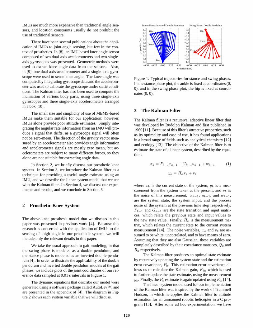
We take the usual approach to gait modeling, in thatthe swing phase is modeled as a double pendulum, andthe stance phase is modeled as an inverted double pendu-lum [4]. In order to illustrate the applicability of the doublependulum and inverted double pendulum models of the gaitphases, we include plots of the joint coordinates of our ref-erence data sampled at 0.01 s intervals in Figure 1.
The dynamic equations that describe our model weregenerated using a software package called AutoLev™, andare presented in the appendix of [4]. The diagram in Fig-ure 2 shows each system variable that we will discuss.
−0.50 −0.25 0.00 0.25 0.500.00.10.20.30.40.50.60.70.80.91.0
x−position (m)
y−po
sitio
n (m
)
Stance Phase: Inverted Double Pendulum
−0.50 −0.25 0.00 0.25 0.50−1.0−0.9−0.8−0.7−0.6−0.5−0.4−0.3−0.2−0.1
0.0
Swing Phase: Double Pendulum
Foot
Knee
HipHip
Foot
Knee
Figure 1. Typical trajectories for stance and swing phases.In the stance phase plot, the ankle is fixed at coordinates (0,0), and in the swing phase plot, the hip is fixed at coordi-nates (0, 0).
3 The Kalman Filter
The Kalman filter is a recursive, adaptive linear filter thatwas developed by Rudolph Kalman and first published in1960 [11]. Because of this filter’s attractive properties, suchas its optimality and ease of use, it has found applicationsin a broad range of fields such as analytical chemistry [12]and ecology [13]. The objective of the Kalman filter is toestimate the state of a linear system, described by the equa-tions
xk = Fk−1xk−1 +Gk−1uk−1 + wk−1 (1)
yk = Hkxk + vk
wherexk is the current state of the system,yk is a mea-surement from the system taken at the present, andvk isthe noise of this measurement.xk−1, uk−1, andwk−1,are the system state, the system input, and the processnoise of the system at the previous time step respectively.Fk−1 andGk−1 are the state transition and input matri-ces, which relate the previous state and input values tothe new state value. Finally,Hk is the measurement ma-trix, which relates the current state to the current systemmeasurement [14]. The noise variables,wk andvk are as-sumed to be white, uncorrelated, and to have means of zero.Assuming that they are also Gaussian, these variables arecompletely described by their covariance matrices,Qk andRk respectively.
The Kalman filter produces an optimal state estimateby recursively updating the system state and the estimationerror covariance,Pk. This estimation error covariance al-lows us to calculate the Kalman gain,Kk, which is usedto further update the state estimate, using the measurementyk. Finally, thePk estimate is again updated usingKk [14].
The linear system model used for our implementationof the Kalman filter was inspired by the work of TrammellHudson, in which he applies the Kalman filter to attitudeestimation for an unmanned robotic helicopter in a C pro-gram [15]. After some ad hoc experimentation, we have
120

Figure 2. Diagram of the prosthesis in the sagittal plane,showing the relevant variables used in our models.φ1 isthe thigh angle,φk is the knee angle, and̂φ1 is an estimateof the thigh angle.ax anday are the axes along whichthe IMU measures acceleration andg is acceleration dueto gravity. Finally,ω is the angular velocity measurementmade by the IMU, andφa andφω are estimates of the thighangle produced by acceleration and angular velocity mea-surements respectively.
developed a scalar Kalman filter model that performs bet-ter than the Kalman filter in [15] for our application. Af-ter substituting the state, measurement, and input variablesinto (1), we get
φ1k= φ1k−1
+ ωk−1 + wk−1 (2)
tan−1
(
ayk
axk
)
= φ1k+ vk
whereφ1k−1andφ1k
are the previous and new thigh angleestimates,ωk−1 is the previous angular rate input, andaxk
andaykare acceleration measurements from a two-axis ac-
celerometer whose axes span the sagittal plane. We makethe assumption that the only acceleration measured by theaccelerometer is from gravity, which allows us to easilycompute the angle of the accelerometer with respect to thegravity vector, which is equivalent toφ1. By definingykas the inverse tangent of the quotient ofax anday insteadof a vector containingax anday, we avoid introducing thenonlinear inverse tangent function into our model, and sowe are able to use the standard Kalman filter and the linearsystem model given in (1).
The a priori information given to the filter for its firstiteration isφ1k
= 0° , andPk = 1. We generally cannotknow whatφ1 is when we begin applying the Kalman filter,but since the range ofφ1 is [-90°, 90°], an initial estimateof zero will have an error less than 90°. Also, by settingPk
= 1, we are telling the filter that our initial state estimate
may be erroneous. This will cause the filter to convergeto steady state more quickly than if we use smaller initialvalues forPk.
4 IMU Experiments
We performed the following experiment to test the effi-cacy of our IMU based angle sensor. For an initial proofof concept test, we collected raw acceleration and angu-lar velocity data from the built-in accelerometer and gy-roscope in the iPhone 4® with a data acquisition applica-tion, while simultaneously collecting reference angle datafrom a potentiometer-based thigh angle sensor; the sam-pling rate for both sensors was 100 Hz. Data from bothsensors was collected for a 19 second interval, in whichthe subject made ten strides. Figure 3 shows the referencethigh angle measurement taken with the potentiometer, aswell as the estimates produced by Euler integration of theangular rate data, and the Kalman filter.
0 5 10 15−30
0
30
60
90
time (seconds)
angl
e (d
egre
es)
φ1 (reference)
φ1 (unfiltered)
φ1 (filtered)
Figure 3. Plots of thigh angle estimates produced by an-gular rate data from a gyroscope (unfiltered), voltage datafrom a potentiometer (reference), and our Kalman filter.
The subject made a 90° pivot after five strides in or-der to take five more strides in a different direction. Thispivot introduced a disturbance into the angular rate signal,which, when integrated, caused a bias to be introduced intothe resulting angle estimate. The angle estimate from theKalman filter did not exhibit this bias after the pivot, whichis a desirable feature. A good indicator of the relative per-formance of the Kalman filter angle estimate is its errorwith respect to the reference angle. Figure 4 shows the ab-solute value of error of the thigh angle estimates for the 19second experiment.
Visual inspection of Figure 4 shows the accumulationof angle error due to drift in the unfiltered data. It alsoshows that the Kalman filter error does not exhibit this drift,and that it is relatively consistent from one gait cycle tothe next. The Kalman filter error may be larger than theintegrated angular rate error for the first few gait cycles, butit soon becomes relatively small compared to the unfiltereddata after the subject pivots.
The integral of squared error (ISE) of theφ1 esti-mate from the Euler integration of gyroscope data is 10,882degree-seconds, and the ISE of theφ1 estimate producedby the Kalman filter is 3180 degree-seconds. Thus, in our
121

0 2 4 6 8 10 12 14 16 180
10
20
30
40
50
time (seconds)
abso
lute
ang
le e
rror
(de
gree
s)
φ
1 error without Kalman filter
φ1 error with Kalman filter
Figure 4. Absolute value of error of thigh angle estimatesproduced with and without our Kalman filter, with respectto the reference thigh angle.
case, the use of the Kalman filter to improve our angle esti-mation results in a 70.8% decrease in thigh angle ISE. Thispercent change suggests that the Kalman filter causes a sig-nificant improvement.
Subsequently, we have collected three sets of IMUdata, taken under different conditions, using discreteMEMS accelerometers and gyroscopes. The same poten-tiometer based thigh angle sensor that was used in the pre-vious experiment was used in these tests as well. Figure 5shows a photo of the equipment worn on the right leg of thesubject.
Figure 5. A photo depicting the locations of the sensorsused in the experiment performed with monolithic sensors.The assembly made of brass and wood is used to mount thepotentiometer at the hip so that it can measure thigh angle.A data aquisition board placed below the potentiometer isused to collect sensor data and transmit it to a laptop that isheld by the subject. A breadboard with the gyroscope andaccelerometer is shown mounted directly above the knee.
We have chosen to collect this data using discrete de-vices instead of the sensors inside of a smartphone becauseonly discrete sensors are feasible for our application and wemust make sure that the discrete sensors work with the fil-ter. It is important to test the thigh angle output of the filterunder all of the conditions in which it will be used, becausethis output will be fed into the closed loop controller of aprosthesis. If the prosthesis controller receives erroneous
feedback data, it may cause its wearer to stumble.For the first data set, we collected 45 seconds of walk-
ing data, and then the subject sits down. The referencethigh angle and the thigh angle computed with the Kalmanfilter are shown in Figure 6.
0 10 20 30 40 50 60−50
0
50
100
time (seconds)
thig
h an
gle
(deg
rees
)
φ1 (reference)
φ1 (filtered)
Figure 6. Thigh angle estimate and potentiometer basedreference thigh angle for the walking and sitting data set.
Theφ1 estimate produced by the Kalman filter tracksthe reference data very well, except when the user sits.While sitting, the thigh angle estimate has an error of about10°, which is still fairly low compared to the errors that canaccumulate in the thigh angle data produced by integratedgyroscope data. The ISE of this thigh angle estimate datais 5182 degree-seconds.
The subject repeatedly sat down and stood up for thesecond data set. Figure 7 shows plots of the reference thighangle and the output of the Kalman filter for this data.
0 2 4 6 8 10 12 14 16 18 20−50
0
50
100
time (seconds)
thig
h an
gle
(deg
rees
)
φ1 (reference)
φ1 (filtered)
Figure 7. Thigh angle estimate and potentiometer basedreference thigh angle for the data set where the subject re-peatedly sits and stands.
The thigh angle output of the Kalman filter tracks thebaseline of the reference data well and the angle increasesand decreases as the user sits just as the reference data does,however, the thigh angle data peaks at a lower value thanthe reference data. The error in the peaks where the subjectsits can be as high as 50°. The ISE value of the thigh angleproduced by the Kalman filter for this data is 28630 degree-seconds. We suspect that the reference data is mostly cor-rect because the thigh angle should come close to 90° whenthe user sits, and the reference data agrees with this; how-ever, the spiky features in the peaks of the reference dataare probably erroneous and did not occur in the real thigh.
122

Therefore the error in the thigh angle may not be as greatas we have measured, but it is still significant.
For the final data set, the subject makes several differ-ent kinds of motions. For the first 18 seconds, the subjectjogs in place, then jumps several times, then walks to aflight of stairs, and at about 67 seconds he starts climbingthem. The data from this set is plotted in Figure 8.
0 10 20 30 40 50 60 70 80−50
−25
0
25
50
time (seconds)
thig
h an
gle
(deg
rees
)
φ1 (reference)
φ1 (filtered)
Figure 8. Thigh angle and potentiometer based referencedata with the data set for a veriety of motions.
Most of the error in the Kalman filter estimate ofφ1
for this this data set occurs when the subject jumps; how-ever, some occurs when the subject climbs stairs at the endof the test. The worst case error is about 15°, and the ISEfor this data is 7872 degree-seconds. Again, this is muchlower than the error that would accumulate in the thigh an-gle from unfiltered integrated gyroscope data after severalseconds of walking. Under all of the motions that we havetested, except for sitting, the thigh angle estimate stays ac-curate.
5 Conclusion
We have shown that the Kalman filter can be used to gener-ate an accurate thigh angle estimate that does not drift usingthe measurements of an IMU. Our work is novel because itis one of the first uses of a Kalman filter to compute thighangle estimates from IMU data for feedback control of aprosthetic leg. We also show that a simple, scalar Kalmanfilter can effectively estimate thigh angle.
In [16], the author mentions that the Kalman filteris very useful for producing a joint angle signal for up-per body joints, but the Kalman filter can be less effectivefor lower body joints, because these limbs can move fasterthan upper body limbs and are subject to large accelera-tions upon heel-strike. These large accelerations may havecontributed to the error of our thigh angle estimates. In ourexperiments, the Kalman filter does not respond well whenthe subject sits. There may also be other situations wherethe Kalman filtered thigh angle is not accurate.
The materials and techniques used to mount our sen-sors, as shown in Figure 5, were poor, so our results mayhave a significant amount of systematic error. Further, ourKalman filter may be suffering from mismodeling errors,because the bulk of the Kalman filter error occurs in thesecond half of each gait cycle, while this is not true for the
integrated angular rate error. We suspect mismodeling maybe the cause of this problem in the Kalman filter becauseour assumption that the accelerometer only measures grav-ity is generally false.
Future work will include running a performance teston the simulation software used in [4]. In this test, we planto model the thigh angle estimation error from our exper-iments as noise and inject this noise into the simulation.This experiment will allow us to conclude whether or notthis IMU based thigh angle sensor will be suitable for ourprosthetic system application. Other future work may in-clude a detailed comparison between different IMU basedjoint measurement techniques. Also, it may be beneficialto develop a more detailed Kalman filter model. We havefound that our scalar Kalman filter model works as well asthe models featuring two state variables that we have tested,but there may be other models that are better.
Acknowledgements
Support for this work was provided by the National Sci-ence Foundation under Grant No. 0826124 and by the Stateof Ohio, Department of Development and Third FrontierCommission, which provided funding to support the RapidRehabilitation and Return to Function for Amputee Sol-diers project.
We would also like to thank Rick Rarick, Tim Wilmot,Steve Szatmary, Dawei Du, and others who have con-tributed to this work – it would not have been possible with-out them.
References
[1] H. Seelen, S. Anemaat, H. Janssen, and J. Deckers,Effects of Prosthesis Alignment on Pressure Distribu-tion at the Stump/Socket Interface in Transtibial Am-putees During Unsupported Stance and Gait,ClinicalRehabilitation, 17(7), 2003, 787-796.
[2] S. Gard and R. Konz, The Effect of a Shock-Absorbing Pylon on the Gait of Persons with Uni-lateral Transtibial Amputation,Journal of Rehabili-tation Research and Development, 40(2), 2003, 109-124.
[3] J. Kim and J. Oh, Development of an Above KneeProsthesis using MR Damper and Leg Simulator,Proceedings of the 2001 IEEE International Confer-ence on Robotics & Automation,Seoul, Korea, 2001,3686-3691.
[4] T. Wilmot, Intelligent Controls for a Semi-Active Hydraulic Prosthetic Knee, ClevelandState University, Department of Electricaland Computer Engineering, Master’s Thesis,http://www.csuohio.edu/engineering/ece/research/thesis.html, 2006.
123

[5] R. Dorf, Modern Control Systems, 6th edition(Boston, MA: Addison Wesley, 1992).
[6] N. Barbour and G. Schmidt, Inertial Sensor Technol-ogy Trends,IEEE Sensors Journal, 1(4) 2001, 322-339.
[7] L. Song, X. Wang, S. Gong, Z. Shi, and L. Chen, De-sign of Active Artificial Knee Joint,7th Asian-PacificConference on Medical and Biological Engineering,Beijing, China, 2002, 155-158.
[8] H. Dejnabadi, B. Jolles, and K. Aminian, A New Ap-proach to Accurate Measurement of Uniaxial JointAngles Based on a Combination of Accelerometersand Gyroscopes,IEEE Transactions on BiomedicalEngineering, 52(8), 2005, 1478-1484.
[9] R. Mayagoitia, A. Nene, P. Veltink, Accelerometerand rate gyroscope measurement of kinematics: aninexpensive alternative to optical motion analysis sys-tems,Journal of Biomechanics, 35(4), 2002, 537542.
[10] H. Luinge and P. Veltink, Measuring orientation ofhuman body segments using miniature gyroscopesand accelerometers,Medical & Biological Engineer-ing & Computing, 43(2), 2005, 273-282.
[11] R. Kalman, A New Approach to Linear Filtering andPrediction Problems,Journal of Basic Engineering,82, 1960, 35-45.
[12] S. Brown, The Kalman Filter in Analytical Chemistry,Analytica Chimica Acta, 181, 1986, 1-26.
[13] S. Lindley, Estimation of Population Growth and Ex-tinction Parameters from Noisy Data,Ecological Ap-plication, 13(3), 2003, 806-813.
[14] D. Simon, Optimal State Estimation: Kalman, H-Infinity, and Nonlinear Approaches, 1st Edition(Hoboken, NJ: John Wiley & Sons, 2006).
[15] T. Hudson, Rotomotion Autopilot Package: tilt.c,http://www.rotomotion.com/downloads/tilt.c, 2003.
[16] M. Djuric-Jovicic, N. Jovicic, and D. Popovic, Kine-matics of Gait: New Method for Angle EstimationBased on Accelerometers,Sensors, 11(11), 2011,10571-10585.
124