industry report structural steelwork · pdf fileindustry report structural steelwork in action...
TRANSCRIPT
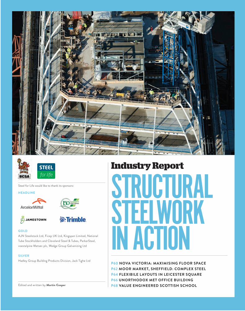
P60 NOVA VICTORIA: MAXIMISING FLOOR SPACE P62 MOOR MARKET, SHEFFIELD: COMPLEX STEELP64 FLEXIBILE LAYOUTS IN LEICESTER SQUARE P66 UNORTHODOX MET OFFICE BUILDING P68 VALUE ENGINEERED SCOTTISH SCHOOL
Steel for Life would like to thank its sponsors:
HEADLINE
GOLD AJN Steelstock Ltd, Ficep UK Ltd, Kingspan Limited, National Tube Stockholders and Cleveland Steel & Tubes, ParkerSteel, voestalpine Metsec plc, Wedge Group Galvanizing Ltd
SILVERHadley Group Building Products Division, Jack Tighe Ltd
Edited and written by Martin Cooper
Industry Report STRUCTURAL STEELWORK IN ACTION
BARRETTSTEEL LIMITED

Freeing SpaceSteel Frame HelpS developer maximiSe Floor Space in london’S victoria
A new and vibrant office, retail and residential area known as Nova is being created in Victoria, central London, as this area of SW1 gets a thorough makeover, with steel construction playing a leading role.
The first phase started in June 2013 and when it is complete later this year it will provide 44,600m2 of offices, 7,500m2 of retail and restaurant space, and 170 luxury modern apartments within three landmark buildings.
This prestigious project’s location has thrown up a number of challenges for main contractor Mace, as project director Tony Palgrave explains: “The site is surrounded by busy roads, so logistics are complicated, we have theatres and hotels close by which means we have to keep noise levels down at certain times. The Victoria Underground Station upgrade works are ongoing right next to our site, while below us there is a protected zone for the forthcoming Crossrail 2 project. We also have to contend with two major sewers, one of which runs right across our site.”
All of the project’s main challenges have been overcome and the job, including the steel construction programme, is on schedule. The major steel construction elements of Nova are the 15-storey North and 21-storey South office blocks. As well as Grade A office accommodation, both of these buildings will have ground and first floor retail and restaurant spaces.
“At the early design stage we had concrete and steel alternatives for the office blocks,” says Robert Bird group managing director David Seel. “Steel was the best option to create the premium office space desired, as it meant we could halve the amount of internal columns.”
Key fact
9,000tAmount of structural steel used
Together these steel-framed structurally independent buildings occupy just over half of the site’s footprint. Interestingly, the gap between the buildings has been designed to correspond to the Crossrail 2 exclusion zone, so piling was not possible in this area.
The superstructure’s steel frames begin at ground floor level with a complex connection to the site’s numerous plunge columns (see box). As many of the columns are inclined, Severfield had to ensure the plunge to structural column connection joined exactly.
Based around centrally positioned concrete cores, both steel frames are erected on a 9m-perimeter grid pattern with some internal spans of up to 16m. Each building features a mix of vertical and inclined façades and this sloping geometry has necessitated the use of bespoke fabricated box section columns, measuring up to 600mm by 300mm.
Complex inclined roofs adorn Nova North and South, with the latter building having by far the most complex steel-framed roof as it slopes in two opposing directions.
To erect these high-level steel lattice structures, a huge piece-count of individual steel members has been lifted into place to form wedge-shaped prisms. Much of the roof steelwork is galvanized, because it will be left exposed to the elements.
Nova North has an inclined roof and flat architectural featured roof grillage. The roof extends from levels 10 to 15, all of which are plant spaces with the exception of one upper floor, which has office space.
Topping Nova South are two inclined roofs, containing plant levels from 10 to 15 and then upwards from 16 into an architectural peak at level 21. Again, the uppermost level of this block also contains plant areas.
STRUCTURAL STEELWORK IN ACTION
60 n e w c i v i l e n g i n e e r | m ay 2016
B Y M A R T I N C O O P E R

“The roofs, especially the South which pitches in two directions, are made up of bespoke steel elements,” says Severfield contracts manager Martin Clyne.
Two trusses add to the complexity of the South roof. The truss members were delivered to site as individual sections and lifted by the tower crane to the level 10 slab, which was used as a temporary laydown area during erection.
Each truss was built up in its final position and due to its shape, was temporarily propped with a column and jacking system from the Level 10 slab. Once the first section was securely in position, the remainder of the sections were built from it. Once complete, the trusses support the Level 11 and 12 plant room floors. On the North roof, a transfer girder was designed and installed at Level 12 due to the long span between columns. The girder is 15.4m long and 1.5m in depth and weighs 25.3t. The completed girder was heavier than the tower crane’s capacity and so it had to be spliced at three points.
“A temporary propping system was installed from Level 12 down to Level 10 ahead of the delivery of the girder. Once all of the sections were bolted and restrained the temporary propping system was removed leaving the girder self-supporting,” sums up Clyne
A top-down construction method, whereby the basement works were undertaken simultaneously with the building of the project’s superstructure, was used on Nova.
“it’s all about getting the steel frame started as quickly as possible and the top-down method allows this by creating a much faster programme,” says robert Bird group managing director David Seel.
The project’s basement covers the entire site and is four levels deep. To create this large space, early works included making sure ground movements were kept to a minimum to protect the major sewer that cuts across the site and to protect the nearby london Underground lines and the new victoria Station pedestrian tunnels.
a number of existing piles from previous buildings had to be located prior to the installation of 240 steel
plunge columns that consist of 40 different profiles and are installed to a depth of up to 20m.
The majority of the existing piles have been left in the ground, but a few had to be extracted as their position would have hindered the project’s desired 9m by 9m steel grid pattern.
Some plunge columns acted as temporary supports for the cores, so they could be constructed early in the programme, in turn allowing the steelwork to start sooner.
“Using steel plunge columns gave us two advantages,” adds Seel. “They acted as temporary steel supports for the cores and then later they were cast in concrete to become part of the project’s composite reinforcement.”
in total more than 2,000t of the overall 9,000t steel tonnage supplied and fabricated by Severfield has been used below ground level at nova.
Project : Nova VictoriaMain c l ient : Land SecuritiesArchitect : PLPMain contractor : MaceStructural engineer : Robert Bird GroupSteelwork contractor : Severfield
Below groUnD workS
PROjECT TEAM
“As many of the columns are inclined, Severfield has
to ensure the plunge to structural column connection joined exactly
61m ay 2016 | n e w c i v i l e n g i n e e r

Frame gameSheFField retail project bringS complex Steelwork challengeS
Sheffield has embarked on an ambitious programme of regeneration that will transform the city centre into one of the region’s most desirable shopping areas.
Phase one of this programme centred around the completion of a new indoor Moor Market and
nine retail units, while the current phase two – which kicked off in early 2015 – will deliver a three-level Primark store, a nine-screen cinema complex, restaurants and retail units all serviced by a large delivery yard.
Further phases are scheduled to begin later this year with more retail space in new and refurbished buildings.
Phase two is essentially split into two structurally independent steel-framed buildings, separated by a 70mm wide movement joint. One building is a standalone Primark store, while the other much larger structure accommodates the remainder of the scheme’s amenities.
Main contractor Bowmer & Kirkland started phase two during March 2015 and, as the site had previously been cleared, the first task was to install foundations.
“Ground conditions have been more challenging than we initially anticipated, so we’ve had to reschedule the steel programme accordingly,” says Bowmer & Kirkland project manager Keith Birtwistle.
“It would have been easier, in terms of logistics and getting materials onto site, to erect the larger frame first and finish the steel erection with the Primark store,” he adds.
“However, as groundworks were ongoing, we had to do the reverse and erect the Primark store first.”
Since the Primark store has been erected, site access for steelwork has been more challenging as the erected frame now blocks one of the previous entry points.
STRUCTURAL STEELWORK IN ACTION
“ It’s a sway frame in
two directions, as we wanted to avoid bracing
62 n e w c i v i l e n g i n e e r | m ay 2016

shorter trusses positioned at a 45 ̊angle to the larger members.The trusses vary in weight considerably, with the lightest
only 7t and the heaviest coming in at 39t. “Their weight depends on their position and the amount
of column loadings they are going to absorb,” explains Hambleton Steel Site Manager Andrew Aykroyd.
The loadings differ as the steel complexity increases above the service yard trusses. This is because, as well as forming the roof over the yard, the trusses provide support to a host of columns forming the upper storey mall and the cinema.
The cinema steel frame superstructure (third floor and above) comprises two rows of mono-pitched portal frames, spanning over the screening rooms at approximately 4m centres.
In addition, a number of columns were off-set to allow for clear access to a sloping second floor pedestrian walkthrough mall. Therefore a series of transfer beams within the third floor structure has been utilised to support the cinema floor over the service yard.
Access to the cinema, restaurants and first floor shopping mall will be via an escalator link from the Moor.
Further trusses are located above the auditoriums, including a 17t 24m-long truss that will be installed at roof level. Also at this level are a series of 30m-long rafters forming the mono-pitch roof.
For ease of transportation, these long sections, each weighing 2.5t, will be brought to site in three pieces.
The service yard trusses, on the other hand, arrive on site in two pieces, which are then bolted together on the ground before being lifted into place using two mobile cranes.
The Moor phase two is due to be completed in October.
Key fact
2,200tAmount of structural steel used
This means steelwork contractor Hambleton Steel has to make deliveries during early mornings and evenings, as these are the only times when the pedestrianised Moor shopping street can be closed. Meanwhile, larger steel elements are delivered via Debenhams’ adjacent temporary service yard, which overlooks the site.
Debenhams has a vested interest in the project as the site’s neighbour. Once the development is complete, it will be able to dispense with the temporary yard and once again use its main loading bays, which will be accessed via the new delivery yard.
The three level Primark store was constructed around a fairly typical retail-sized grid pattern of 8m by 8m.
There are a few slight variations to this pattern, most notably around lift and stair cores, and in order to accommodate the ground floor access ramp to the development’s delivery yard.
“It’s a sway frame in two directions, as we wanted to avoid bracing,” explains Sanderson Watts Associates engineer Ryan McMullan.
“The building has glazed shop front elevations which aren’t suitable for bracing as the client didn’t want them in view, so we could only position supplementary cross bracings in discrete back-of-house locations.”
The building’s suspended floors and plant roof are designed to act compositely with the supporting steelwork beams, via shear studs welded to the beam flanges.
One of the most challenging parts of the steel programme was the initial phase of the large mixed-use structure. A total of eleven 26m-long by 2.5m-deep trusses had to be installed to form the large column-free space of the delivery yard.
To complete the yard’s roof, there are a further seven
Right: The project will radically change the city centreFar right: The cinema takes shape
Project : Sheffield MoorMain c l ient : Aberdeen Property TrustArchitect : Leslie Jones ArchitectureMain contractor : Bowmer & KirklandStructural engineer : Sanderson Watts AssociatesSteel contractor : Hambleton Steel
PROJECT TEAM
63m ay 2016 | n e w c i v i l e n g i n e e r

Spread the loadSteel frame within retained faÇade increaSeS floor layout flexibility
T he retention of London’s listed façades has become a widespread feature of construction projects in the capital during the last decade.
Whether projects involve partial or complete façade retentions, the importance of keeping these historic, and quite often
listed street frontages is vital in maintaining London’s traditional streetscape.
Developers and tenants alike want modern spacious offices and the best way of attaining this on a plot, which has a listed façade, is to demolish the building’s innards while propping and retaining the perimeter walls. A new modern structure can then be built behind the walls and incorporate the historic or listed façade.
One of Europe’s largest retained façades is currently being incorporated into the redevelopment of LSQ London in central London.
Formerly known as Communications House, this 1920s building, which overlooks one of London’s most famous squares, was said to have many attractive features. However, over the past 90 or so years it has been enlarged several times and had become inefficient in terms of maximum utilisation of space.
“Our brief was to create a high-spec office building, and we felt that the goal was not just to reimagine but reinvent, while also retaining the look and feel of the original building, which is liked and admired by so many people,” says Make lead architect Frank Filskow.
“Our design makes the best of the existing building by retaining the historic façades, and sensitively restoring them to maintain the integrity of the original architectural features and details.
“The design of the building naturally leant itself to using steel for the primary structural elements. The design of the new steel structure introduced a new central core and enabled clear, open-plan floorplates, improving the office spaces within the building.”
Waterman Structures director Jody Pearce agrees: “One of the key aspects of a façade retention scheme is the alignment of new floors with existing window openings. We promoted the use of a steel frame as it offered the flexibility to suit the various interfaces that occur with the existing façade.”
“By integrating the suspended services within the structural downstand beam zone, the depth of the floor zone against the façade was minimised, thus assisting the alignment of new floors with existing windows further.”
The project’s main contractor Brookfield Multiplex started on site during November 2014, by which time the demolition work had been completed, leaving four propped façades surrounding a cleared site.
“Our first task was to construct a secant piled wall and the main central bearing piles. Then we excavated and enlarged the existing basement into a two-level deep facility, removing 13,000m3 of overburden in the process,” explains Brookfield Multiplex project director Asif Hashmi.
Once this preliminary work and construction of the two main raft slabs were completed, steelwork contractor Bourne Steel was able to begin erecting the new steel frame that begins at lower basement level.
“Getting the steel frame erected and subsequently tied into the existing façade is vital, and it is one of the main drivers of the scheme,” adds Hashmi.
Key fact
2,000tamount of
structural steel used
StRUctURaL SteeLWORK IN actION
64 n e w c i v i l e n g i n e e r | m ay 2016

“Once the frame connecting into the retained façade was erected and the concrete floors cast, we were able to begin removing the extensive façade retention steelwork that surrounds the site and start work on renovating the original stonework and installing new windows.”
The new steel frame is structurally independent and gains its stability from two steel braced cores. Once the temporary propping was removed the new steel frame supports and restrains the four retained façades, and so before the propping could be removed, a large number of connecting brackets had to be installed.
The project’s new steel frame forms two basement levels and a ground floor, which will accommodate high-end retail outlets and a main entrance lobby.
Above the ground floor there are seven floors of office accommodation, five of which are incorporated into the retained façade.
An elegant new curved roof will enclose the two uppermost floors, offering a unique 21st century interpretation of the traditional London mansard style.
The steelwork has been erected around a regular grid pattern with internal spans of up to 15m.
Cellular beams have been utilised throughout for service integration and to minimise the structural void between floors.
The new fifth floor will be clad with Portland stone to integrate with the retained façade below. This floor level’s steelwork is topped with a ring beam that goes around the entire perimeter of the building.
The ring beam is formed from jumbo box sections measuring 650mm by 450mm with a 25mm thickness. The sections were brought to site in 3.5m-long sections
Project: LSQ LondonMain client: Linseed asset Managementclient Development Manager: corearchitect: MakeMain contractor: Brookfield Multiplex construction europeStructural engineer:Waterman StructuresSteelwork contractor:Bourne Steel
PROject teaM
Top right: The feature roof frame will support a lightweight aluminium frame and glazing
Bottom right: The steel frame takes shape within the retained façade
the structure emerges from within the retained façade
each weighing 3t. “The box section ring beam performs two functions,”
says Bourne Steel divisional manager Kevin Springett. “The columns for the feature roof are supported by the beam, as these are not aligned with the main columns for the rest of the building, and the stone cladding for the sixth floor is also hung from the beam.”
The steel feature roof slopes outwards from the two centrally positioned cores and is formed with a cranked steel frame, which in turn supports a lightweight aluminium frame and glazing.
This new and elegant curved mansard roof encloses the building and offers a modern interpretation of the traditional mansard style where arch geometry sits atop a classical base.
“This respectful, contemporary addition to the building composition reduces the existing top-heavy visual mass. The curve also seeks to ensure the building blends in seamlessly with the surrounding buildings of Leicester Square,” sums up Filskow.
LSQ London is scheduled for completion in the third quarter of this year.
“Getting the steel frame erected and subsequently
tied into the existing façade is vital, and it is one of the main drivers of the scheme
65m ay 2016 | n e w c i v i l e n g i n e e r
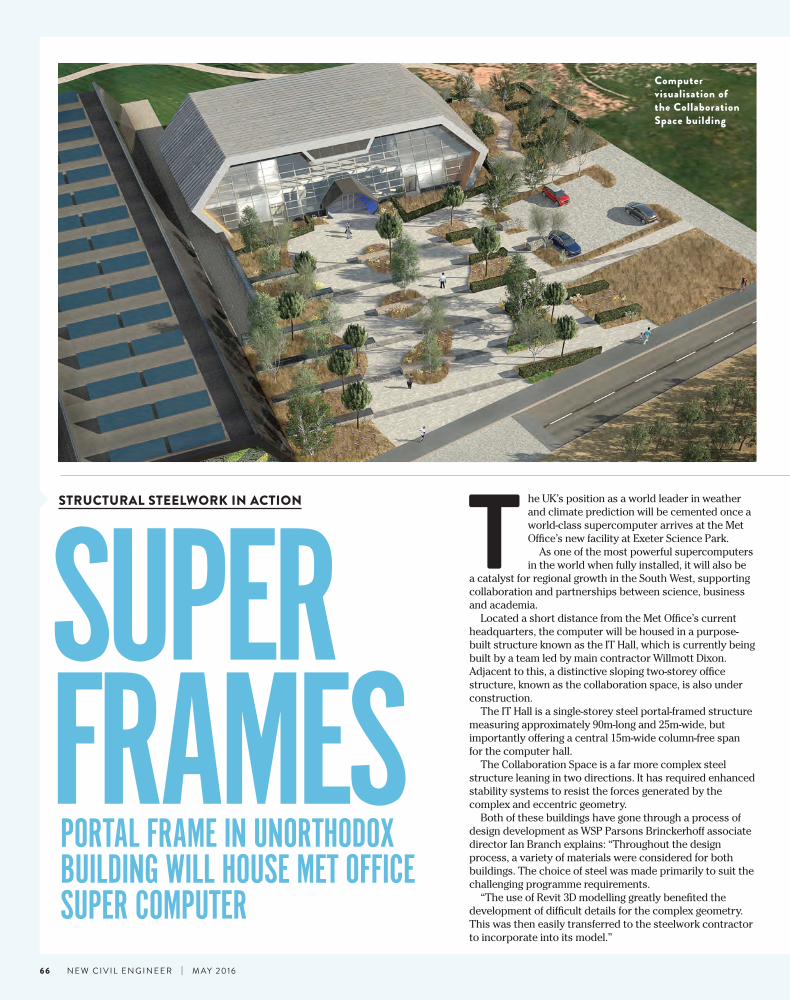
Portal frame in unorthodox building will house met office suPer comPuter
T he UK’s position as a world leader in weather and climate prediction will be cemented once a world-class supercomputer arrives at the Met Office’s new facility at Exeter Science Park.
As one of the most powerful supercomputers in the world when fully installed, it will also be
a catalyst for regional growth in the South West, supporting collaboration and partnerships between science, business and academia.
Located a short distance from the Met Office’s current headquarters, the computer will be housed in a purpose-built structure known as the IT Hall, which is currently being built by a team led by main contractor Willmott Dixon. Adjacent to this, a distinctive sloping two-storey office structure, known as the collaboration space, is also under construction.
The IT Hall is a single-storey steel portal-framed structure measuring approximately 90m-long and 25m-wide, but importantly offering a central 15m-wide column-free span for the computer hall.
The Collaboration Space is a far more complex steel structure leaning in two directions. It has required enhanced stability systems to resist the forces generated by the complex and eccentric geometry.
Both of these buildings have gone through a process of design development as WSP Parsons Brinckerhoff associate director Ian Branch explains: “Throughout the design process, a variety of materials were considered for both buildings. The choice of steel was made primarily to suit the challenging programme requirements.
“The use of Revit 3D modelling greatly benefited the development of difficult details for the complex geometry. This was then easily transferred to the steelwork contractor to incorporate into its model.”
Computer visualisation of the Collaboration Space building
suPer frames
STRUCTURAL STEELWORK IN ACTION
66 n e w c i v i l e n g i n e e r | m ay 2016

“Tubular steelwork was chosen for this part of the
structure for aesthetic reasons, as it will be left fully exposed behind glazing
PROJECT TEAM
Project: Met Office,
ExeterMain client:
The Met Office
Architect: Stride
TreglownMain
contractor: Willmott
DixonStructural engineer:
WSP Parsons Brinckerhoff
Steelwork contractor:
William Haley Engineering
A steel frame was chosen for speed of construction
Once the design was finalised, work started on site last year. The project sits on a greenfield site on the edge of Exeter
Science Park, a recent development on the outskirts of the city that has further expansion plans.
Early works included the installation of pad and strip foundations in readiness for steelwork contractor William Haley Engineering to begin the steel erection programme.
Steelwork erection started with the IT Hall, the simpler of the two frames. This structure had to be the first to be erected as it houses the supercomputer and consequently must be ready first. Powering and serving the computer are a high volume of complex services all of which must be coordinated via 3D modelling in Revit.
Using a single 50t-capacity mobile crane, William Haley erected the IT Hall in approximately three weeks. The propped portal frame has sloping sides formed with raking columns, with two internal column lines providing the large open central space for the computer hall, while the two outer 5m wide spans accommodate ancillary spaces.
As it will house the supercomputer, the IT Hall may be considered to be the more important of the two structures. However, the hexagon-shaped collaboration space was the most challenging to design and erect.
The structure’s accommodation space is based around a two-storey internal box based around a 7.2m by 4.8m grid pattern. The two main elevations, with the front sloping inwards and the back doing the reverse, are built from this steel box.
The internal box was erected first and was initially stabilised by temporary bracing. An insitu concrete lift shaft, combined with moment frames and braced bays within the sloping walls, provided the stability in the final condition.
CHS columns set at an angle of 60° form the two
The supercomputer will be 13 times more powerful than the current system used by the Met Office and will have 120,000 times more memory than a top-end smartphone.
it will be able to do more than 16,000 trillion calculations per second, and at 140t, will weigh the sams as 11 double-decker buses.
The supercomputer’s forecasts are anticipated to deliver £2bn of
socio-economic benefits to the UK by enabling better advance preparation and contingency plans to protect homes and businesses.
met Office chief executive rob varley says: “we are very excited about this new investment in UK science. it will lead to a step change in weather forecasting and climate prediction, and give us the capability to strengthen our collaborations with partners in the South west, UK and around the world.”
S U P e r c O m P U T e r F a c T S
Unusual shape: Collaboration space
sloping elevations. “Tubular steelwork was chosen for this part of the
structure for aesthetic reasons, as it will be left fully exposed behind glazing,” explains WSP Parsons Brinckerhoff senior engineer Catherine Mungall.
As well as the two main sloping façades, the structure has two folded ends, formed by two rows of raking CHS columns. To form the fold, the bottom members slope outwards and the top sections slope inwards with a central bolted
connection holding the shape in place. The columns were all designed as moment frames.
As well as the two large glazed façades, the remainder of the collaboration space will be wrapped in zinc cladding.
“To avoid any clashes and deal with the unusual geometry and complex cladding details on this structure we laser- surveyed the building to produce a 3D model,” explains Willmott Dixon’s Leigh Dickson.
“This way of producing a model is very quick and allowed the team to get on with the cladding installation quickly.”
The Met Office supercomputer is being installed in three phases with the final phase due to be completed in Spring 2017.
67m ay 2016 | n e w c i v i l e n g i n e e r

EfficiEncyLEssonVaLuE EnginEErEd stEEL framE for sEcondary schooL takEs shapE in fifE
A new secondary school is being delivered by Bam Construction in Anstruther as part of the ongoing hub Scotland initiative.
Replacing the existing school, the new steel-framed structure will also provide a home for the council’s local office, a
library, a base for police officers, and consequently the project is officially known as The Waid Community Campus incorporating Waid Academy.
The overall campus includes an existing primary school, and a community sports centre, while the 800-place Waid Academy’s new sports facilities, including an all-weather Rugby pitch, will be open to the public at certain times.
Typically, the ground floor of the building houses the community facilities with the school occupying the first and second floors. One of the exceptions is the dining area, which is located within the centrally located atrium.
Work onsite started last year, but before that, the initial design was value engineered to bring the scheme within budget. Without this streamlining design work taking place, the project may not have started at all.
“As well as different cladding systems, the main alteration was to change the roof to a mono-pitched design from one that originally had a multi-pitched roof profile,” explains Bam Construction director Martin Cooper.
The new, economical, pitched roof is said to reflect the project’s rural setting and is a nod to the many agricultural buildings in the surrounding countryside.
With its more economical steel-framed design settled upon, the job was able to kick off, with Bam initially installing a new access road.
“An existing road alongside the construction site is used
by people taking their children to the primary school and by users of the sports centre,” says Cooper.
“It was our decision to construct a new road, and now we have our own dedicated route for deliveries, including the steelwork, which is much safer for all concerned.”
Once the road was completed, a series of piled foundations and a concrete ring beam were installed in advance of the steel erection programme commencing.
Steelwork contractor BHC is fabricating, supplying and erecting 520t of steel for the project. This equates to approximately 1,400 individual pieces, requiring 2,850 connections and a grand total of 16,822 bolts.
During its15-week erection programme, BHC used two 80t-capacity mobile cranes, in conjunction with various sized MEWPs, to erect the entire steel frame and install metal decking and precast planks.
The speed of the erection process and the knock-on effects this has for the whole construction programme was the main reason for choosing steel as the framing solution, according to BDP project architect Stuart Duncan.
The building is roughly square-shaped in plan, with each elevation measuring approximately 65m-long. For the erection programme, the building was divided into three zones, with each one completed to its full height before BHC moved onto the next one.
BHC’s second mobile crane would then follow on behind the steel erection gang and install the flooring systems for each completed zone. The three zones corresponded to the structure’s two outer wings, and a central zone encompassing the building’s large atrium and drama hall.
Aecom project engineer Craig Kempsell says: “We proposed a combination of flooring construction,
Key facts
16,822Number of bolts used
520Tonnes of
steel used in the project
Main picture: The steel frame and flooring were erected and installed by mobile cranes. Top right: Computer rendering of the atrium
STRUCTURAL STEELWORK IN ACTION
68 n e w c i v i l e n g i n e e r | m ay 2016
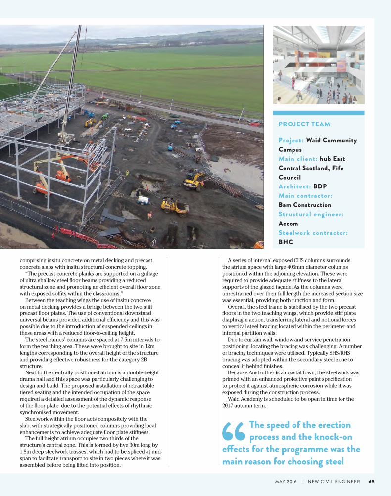
comprising insitu concrete on metal decking and precast concrete slabs with insitu structural concrete topping.
“The precast concrete planks are supported on a grillage of ultra shallow steel floor beams providing a reduced structural zone and promoting an efficient overall floor zone with exposed soffits within the classrooms.”
Between the teaching wings the use of insitu concrete on metal decking provides a bridge between the two stiff precast floor plates. The use of conventional downstand universal beams provided additional efficiency and this was possible due to the introduction of suspended ceilings in these areas with a reduced floor-to-ceiling height.
The steel frames’ columns are spaced at 7.5m intervals to form the teaching area. These were brought to site in 12m lengths corresponding to the overall height of the structure and providing effective robustness for the category 2B structure.
Next to the centrally positioned atrium is a double-height drama hall and this space was particularly challenging to design and build. The proposed installation of retractable tiered seating and the intended occupation of the space required a detailed assessment of the dynamic response of the floor plate, due to the potential effects of rhythmic synchronised movement.
Steelwork within the floor acts compositely with the slab, with strategically positioned columns providing local enhancements to achieve adequate floor plate stiffness.
The full height atrium occupies two thirds of the structure’s central zone. This is formed by five 30m long by 1.8m deep steelwork trusses, which had to be spliced at mid-span to facilitate transport to site in two pieces where it was assembled before being lifted into position.
Project : Waid Community CampusMain c l ient : hub East Central Scotland, Fife CouncilArchitect : BDPMain contractor : Bam Construction Structural engineer : Aecom Steelwork contractor : BHC
PROjECT TEAM
A series of internal exposed CHS columns surrounds the atrium space with large 406mm diameter columns positioned within the adjoining elevation. These were required to provide adequate stiffness to the lateral supports of the glazed façade. As the columns were unrestrained over their full length the increased section size was essential, providing both function and form.
Overall, the steel frame is stabilised by the two precast floors in the two teaching wings, which provide stiff plate diaphragm action, transferring lateral and notional forces to vertical steel bracing located within the perimeter and internal partition walls.
Due to curtain wall, window and service penetration positioning, locating the bracing was challenging. A number of bracing techniques were utilised. Typically SHS/RHS bracing was adopted within the secondary steel zone to conceal it behind finishes.
Because Anstruther is a coastal town, the steelwork was primed with an enhanced protective paint specification to protect it against atmospheric corrosion while it was exposed during the construction process.
Waid Academy is scheduled to be open in time for the 2017 autumn term.
“The speed of the erection process and the knock-on
effects for the programme was the main reason for choosing steel
69m ay 2016 | n e w c i v i l e n g i n e e r