industry asia pacific 10
DESCRIPTION
Industry Asia Pacific is the portal for Asia technical engineers.TRANSCRIPT
PEPPERL-FUCHS FDH-1: FROM THE VERY
FIRST CLICK
30
SICK BULKSCAN® LMS511
LASER VOLUME FLOWMETER
4
THE INDUSTRY MAGAZINE FOR ASIA
10 | J U LY 2015
Asia PacificIndustry
KENNAMETALACHIEVE FLOW TUNING EXCELLENCE WITH THE NEW EXTRUDE HONE™ MF PROGRESS™
12
BONFIGLIOILIFDK AND FZP VERSIONS: NEW EASY MAINTENANCE SERIES
16

THE INDUSTRY MAGAZINE FOR ASIA
10 | Industry Asia Pacific | July 2015
SICK
4EMERSON
ALTERNATOR
6
DE DIETRICH PROCESS SYSTEMS
7
NORD
8SOFTING
9JUNGHEINRICH
10
KENNAMETAL
12WIDIA
14BONFLIGLIOLI
16
SECO TOOLS
18
BONFLIGLIOLI
28
NORD
21
SECO TOOLS
29
EPLAN
22
PEPPERL+FUCHS
30
BALLUFF
24PEPPERL
+FUCHS
25EPLAN
26
www.industry-asia-pacific.com

10 | Industry Asia Pacific | July 2015
3
BAUMER
32HMS
33HMS
34

10 | Industry Asia Pacific | July 2015
4
N E W SMORE
INFORMATION
Those looking to measure quantities of bulk materials on belts can now opt for a precise measuring process in the form of the Bulkscan® LMS511. Up until now
traditional belt scales have always been used. These are simple and cost-effective, but they do have their pitfalls. Operators tend to experience problems when it comes to the accuracy of the weight measurement.
The low level of measurement stability and the sensitivity of these devices, particularly in harsh conditions, also interfere with the production process. This process is a lot easier if the system can monitor mass flow as well as volume flow. This requires non-contact laser technology to be installed in rugged hardware suitable for outdoor use.
Volume, level, and center of gravity The Bulkscan® LMS511 measures volume flow continuously in a non-contact process and also identifies the fill level and the center of gravity of bulk materials on belts. And thanks to multi-echo technology, it always works regardless of the weather (rain, snow, fog, dust) or the composition of the material at hand. Not even reflections in glass can disrupt the laser volume flowmeter. The laser beam detects the height profile of the bulk materials as well as volume and throughput, at sensing ranges of up to 20 meters. For instance, stones of an excessive size can be detected in good time, before they are able to block downstream system components. Using the integrated center of gravity calculation, the scanner monitors the belt load over the complete conveying line and recognizes one-sided loads or one-sided belt loads. It can even detect movements in the belt at an early stage, helping to make sure that the belt does not suffer high levels of wear and tear.
Anyone who uses conveyor systems in their working environment knows that incorrect measurements must be avoided, otherwise the machines and belts could be so badly damaged that production comes to a complete stop. Dedicated to harsh environment, the Bulkscan® LMS511accurately measures mass and volume flow continuously in a non-contact process and also identifies the fill level and the center of gravity of bulk materials on belts.
BULKSCAN® LMS511 LASER VOLUME FLOWMETER
N E W S
10 | Industry Asia Pacific | July 2015
5
MORE
INFORM
ATION
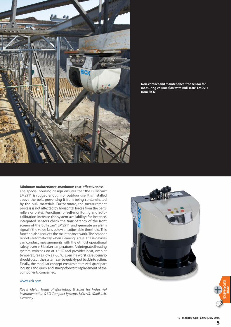
Non-contact and maintenance-free sensor for measuring volume flow with Bulkscan® LMS511 from SICK
Minimum maintenance, maximum cost-effectivenessThe special housing design ensures that the Bulkscan® LMS511 is rugged enough for outdoor use. It is installed above the belt, preventing it from being contaminated by the bulk materials. Furthermore, the measurement process is not affected by horizontal forces from the belt's rollers or plates. Functions for self-monitoring and auto-calibration increase the system availability; for instance, integrated sensors check the transparency of the front screen of the Bulkscan® LMS511 and generate an alarm signal if the value falls below an adjustable threshold. This function also reduces the maintenance work. The scanner reports automatically when cleaning is due. These devices can conduct measurements with the utmost operational safety, even in Siberian temperatures. An integrated heating system switches on at +5 °C and provides heat, even at temperatures as low as -30 °C. Even if a worst case scenario should occur, the system can be quickly put back into action. Finally, the modular concept ensures optimized spare part logistics and quick and straightforward replacement of the components concerned.
www.sick.com
Xaver Meier, Head of Marketing & Sales for Industrial Instrumentation & 3D Compact Systems, SICK AG, Waldkirch, Germany
10 | Industry Asia Pacific | July 2015
6
N E W SMORE
INFORMATION
“The launch of these new products demonstrates our continuous commitment to innovation and growth.” said Xavier Trenchant, President of the Electric Power Generation division “In a challenging economic environment, we continue to invest to better anticipate our customers’ expectations. This means that our products are continuously improving to deliver top-of-the-range performances, offering reliable, cost-efficient solutions for demanding applications. We have also recently extended our offering to provide a competitive solution on less demanding applications. Consequently, we do provide the best value proposition to our customers across all power ranges and types of applications, keeping our historical focus on quality and services.”
The LSA 46.3 and LSA 49.3 are optimized for continuous and demanding applications, including marine, power plants, cogeneration, rental or critical standby in commercial and industrial premises.The Leroy-Somer LSA 46.3 and LSA 49.3 will be available to order starting Q3 2015.
For more information, please visit www.emersonindustrial.com/electricpowergeneration
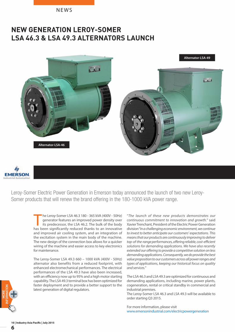
The Leroy-Somer LSA 46.3 180 - 365 kVA (400V - 50Hz) generator features an improved power density over its predecessor, the LSA 46.2. The bulk of the body
has been significantly reduced thanks to an innovative and improved air cooling system, and an integration of the excitation system in the main body of the machine. The new design of the connection box allows for a quicker wiring of the machine and easier access to key electronics for maintenance.
The Leroy-Somer LSA 49.3 660 – 1000 kVA (400V - 50Hz) alternator also benefits from a reduced footprint, with enhanced electromechanical performances. The electrical performances of the LSA 49.3 have also been increased, with an efficiency now up to 95% and a high motor starting capability. The LSA 49.3 terminal box has been optimized for faster deployment and to provide a better support to the latest generation of digital regulators.
Leroy-Somer Electric Power Generation in Emerson today announced the launch of two new Leroy-Somer products that will renew the brand offering in the 180-1000 kVA power range.
Alternator-LSA-49
Alternator-LSA-46
NEW GENERATION LEROY-SOMER LSA 46.3 & LSA 49.3 ALTERNATORS LAUNCH
10 | Industry Asia Pacific | July 2015
7
N E W SMORE
INFORM
ATION
De Dietrich, which recently scored new successes that provide it with opportunities for sustainable growth, is continuing its international expansion and has secured, in China, the biggest deal in its history.
In related pharmaceutical news, De Dietrich is going to build a complete antihistamine production plant in Spain. This turnkey project will include the production building itself, all the necessary reaction and separation equipment, and all the associated equipment. Production of the first batches will begin in one year's time.
Back in its home country of France, De Dietrich has just signed a green-chemistry partnership agreement to equip a research platform for the production of chemical molecules from renewable oilseed crops.
http://dedietrich.co.in
Under the deal, De Dietrich will deliver a waste acid treatment system for a new toluene diisocyanate plant to be built in northwest China. Toluene diisocyanate
(TDI) is used in the manufacture of polyurethane. The Chinese government, which has significantly tightened the country's environmental standards, was impressed by De Dietrich's highly efficient effluent treatment and purification processes. The project, which is scheduled for completion in 2017, will be the largest ever undertaken by De Dietrich and will further strengthen China as the group's largest source of sales.
De Dietrich has also been selected to deliver a complete pilot unit for the first company in Bangladesh to ever begin manufacturing active pharmaceutical ingredients (API). The project comprises six reactor units, a solvent treatment system, a heating and cooling unit, and automated systems. It will allow De Dietrich to further increase its already strong presence in Southern Asia.
DE DIETRICH ANNOUNCES RECORD ORDERS AT THE ACHEMA TRADE SHOW!
10 | Industry Asia Pacific | July 2015
8
N E W SMORE
INFORMATION
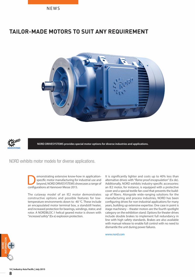
It is significantly lighter and costs up to 40% less than alternative drives with “flame-proof encapsulation” (Ex de). Additionally, NORD exhibits industry-specific accessories: an IE2 motor, for instance, is equipped with a protective cover and a special textile fan cowl that prevents the build-up of fibers. Alongside wide-ranging solutions for the manufacturing and process industries, NORD has been configuring drives for non-industrial applications for many years, building up extensive expertise. One case in point is stage machinery – theater motors are the fourth spotlight category on the exhibition stand. Options for theater drives include double brakes to implement full redundancy in line with high safety standards. Brakes are also available with manual release to enable full control with no need to dismantle the unit during power failures.
www.nord.com
Demonstrating extensive know-how in application-specific motor manufacturing for industrial use and beyond, NORD DRIVESYSTEMS showcases a range of
configurations at Hannover Messe 2015.
The cutaway model of an IE2 motor demonstrates constructive options and possible features for low-temperature environments down to -40 °C. These include an encapsulated motor terminal box, a standstill heater, and increased protection for bearings, windings, stator, and rotor. A NORDBLOC.1 helical geared motor is shown with “increased safety” (Ex e) explosion protection.
NORD exhibits motor models for diverse applications.
NORD DRIVESYSTEMS provides special motor options for diverse industries and applications.
TAILOR-MADE MOTORS TO SUIT ANY REQUIREMENT
10 | Industry Asia Pacific | July 2015
9
N E W SMORE
INFORM
ATION
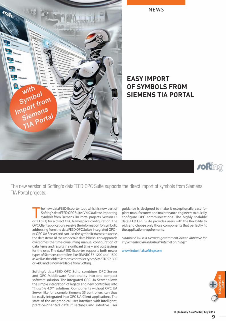
The new dataFEED Exporter tool, which is now part of Softing's dataFEED OPC Suite (V 4.03) allows importing symbols from Siemens TIA Portal projects (version 13
or 13 SP1) for a direct OPC Namespace configuration. The OPC Client applications receive the information for symbolic addressing from the dataFEED OPC Suite’s integrated OPC – or OPC UA Server and can use the symbolic names to access the data items of the respective data blocks. This approach overcomes the time-consuming manual configuration of data items and results in significant time – and cost savings for the user. The dataFEED Exporter supports both newer types of Siemens controllers like SIMATIC S7-1200 and -1500 as well as the older Siemens controller types SIMATIC S7-300 or -400 and is now available from Softing.
Softing‘s dataFEED OPC Suite combines OPC Server and OPC Middleware functionality into one compact software solution. The integrated OPC UA Server allows the simple integration of legacy and new controllers into “Industrie 4.0”* solutions. Components without OPC UA Server, like for example Siemens S5 controllers, can thus be easily integrated into OPC UA Client applications. The state-of-the-art graphical user interface with intelligent, practice-oriented default settings and intuitive user
guidance is designed to make it exceptionally easy for plant manufacturers and maintenance engineers to quickly configure OPC communications. The highly scalable dataFEED OPC Suite provides users with the flexibility to pick and choose only those components that perfectly fit the application requirements.
*Industrie 4.0 is a German government-driven initiative for implementing an industrial "Internet of Things"
www.industrial.softing.com
The new version of Softing's dataFEED OPC Suite supports the direct import of symbols from Siemens TIA Portal projects.
EASY IMPORT OF SYMBOLS FROM SIEMENS TIA PORTAL
10 | Industry Asia Pacific | July 2015
10
N E W SMORE
INFORMATION
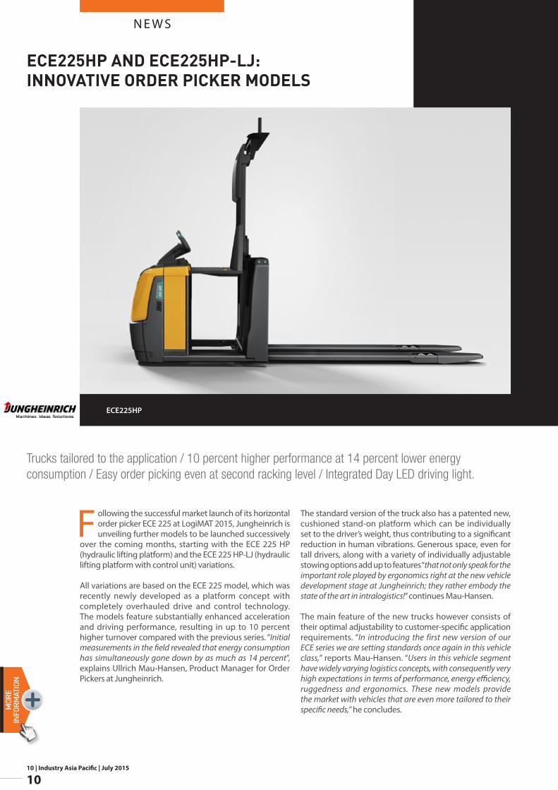
Following the successful market launch of its horizontal order picker ECE 225 at LogiMAT 2015, Jungheinrich is unveiling further models to be launched successively
over the coming months, starting with the ECE 225 HP (hydraulic lifting platform) and the ECE 225 HP-LJ (hydraulic lifting platform with control unit) variations.
All variations are based on the ECE 225 model, which was recently newly developed as a platform concept with completely overhauled drive and control technology. The models feature substantially enhanced acceleration and driving performance, resulting in up to 10 percent higher turnover compared with the previous series. “Initial measurements in the field revealed that energy consumption has simultaneously gone down by as much as 14 percent”, explains Ullrich Mau-Hansen, Product Manager for Order Pickers at Jungheinrich.
The standard version of the truck also has a patented new, cushioned stand-on platform which can be individually set to the driver’s weight, thus contributing to a significant reduction in human vibrations. Generous space, even for tall drivers, along with a variety of individually adjustable stowing options add up to features “that not only speak for the important role played by ergonomics right at the new vehicle development stage at Jungheinrich; they rather embody the state of the art in intralogistics!” continues Mau-Hansen.
The main feature of the new trucks however consists of their optimal adjustability to customer-specific application requirements. “In introducing the first new version of our ECE series we are setting standards once again in this vehicle class,” reports Mau-Hansen. “Users in this vehicle segment have widely varying logistics concepts, with consequently very high expectations in terms of performance, energy efficiency, ruggedness and ergonomics. These new models provide the market with vehicles that are even more tailored to their specific needs,” he concludes.
Trucks tailored to the application / 10 percent higher performance at 14 percent lower energy consumption / Easy order picking even at second racking level / Integrated Day LED driving light.
ECE225HP
ECE225HP AND ECE225HP-LJ: INNOVATIVE ORDER PICKER MODELS
N E W S
10 | Industry Asia Pacific | July 2015
11
MORE
INFORM
ATION
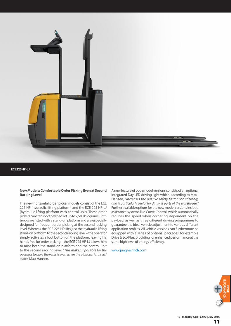
New Models: Comfortable Order Picking Even at Second Racking Level
The new horizontal order picker models consist of the ECE 225 HP (hydraulic lifting platform) and the ECE 225 HP-LJ (hydraulic lifting platform with control unit). These order pickers can transport payloads of up to 2,500 kilograms. Both trucks are fitted with a stand-on platform and are especially designed for frequent order picking at the second racking level. Whereas the ECE 225 HP lifts just the hydraulic lifting stand-on platform to the second racking level – the operator simply activates a foot button on the platform, leaving his hands free for order picking – the ECE 225 HP-LJ allows him to raise both the stand-on platform and the control unit to the second racking level. “This makes it possible for the operator to drive the vehicle even when the platform is raised,” states Mau-Hansen.
A new feature of both model versions consists of an optional integrated Day LED driving light which, according to Mau-Hansen, “increases the passive safety factor considerably, and is particularly useful for dimly lit parts of the warehouse.” Further available options for the new model versions include assistance systems like Curve Control, which automatically reduces the speed when cornering dependent on the payload, as well as three different driving programmes to guarantee the ideal vehicle adjustment to various different application profiles. All vehicle versions can furthermore be equipped with a series of optional packages, for example Drive & Eco Plus, providing for enhanced performance at the same high level of energy efficiency.
www.jungheinrich.com
ECE225HP-LJ
10 | Industry Asia Pacific | July 2015
12
N E W SMORE
INFORMATION
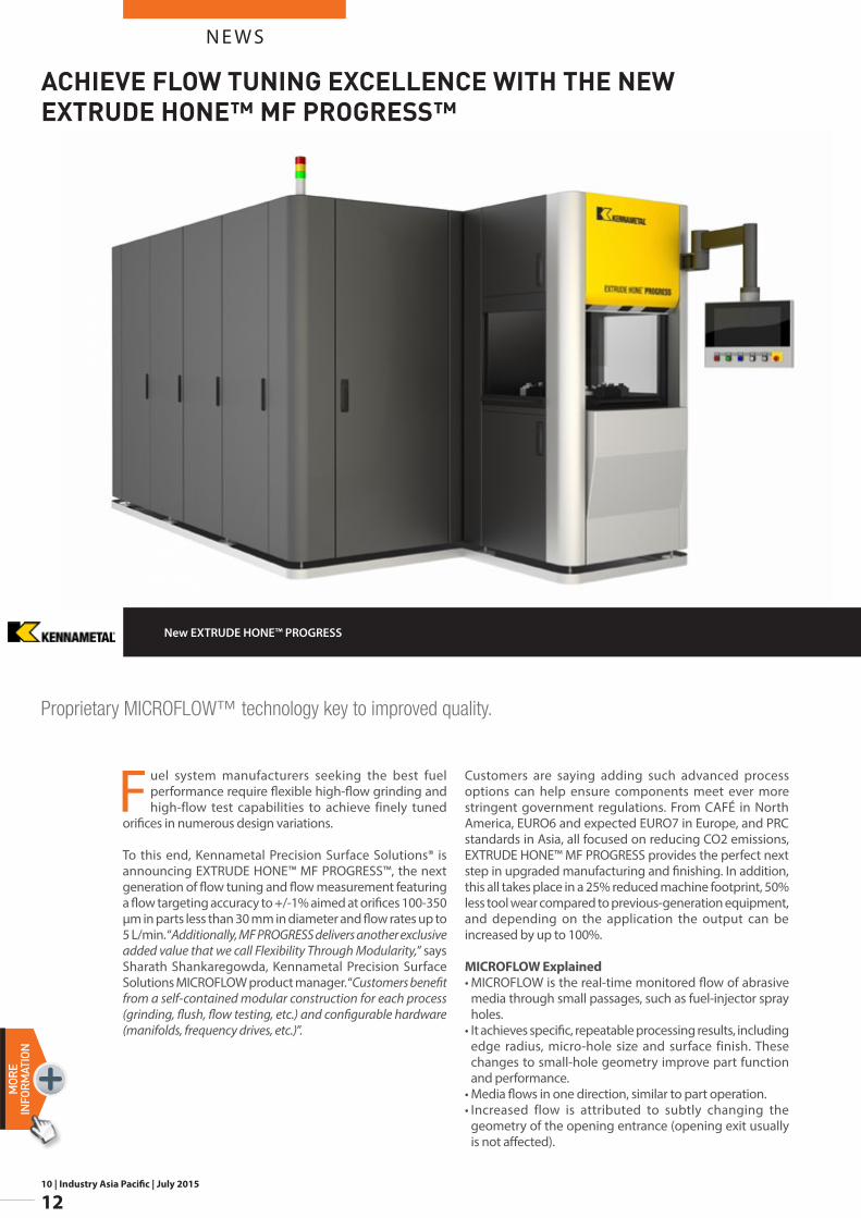
Fuel system manufacturers seeking the best fuel performance require flexible high-flow grinding and high-flow test capabilities to achieve finely tuned
orifices in numerous design variations.
To this end, Kennametal Precision Surface Solutions® is announcing EXTRUDE HONE™ MF PROGRESS™, the next generation of flow tuning and flow measurement featuring a flow targeting accuracy to +/-1% aimed at orifices 100-350 μm in parts less than 30 mm in diameter and flow rates up to 5 L/min. “Additionally, MF PROGRESS delivers another exclusive added value that we call Flexibility Through Modularity,” says Sharath Shankaregowda, Kennametal Precision Surface Solutions MICROFLOW product manager. “Customers benefit from a self-contained modular construction for each process (grinding, flush, flow testing, etc.) and configurable hardware (manifolds, frequency drives, etc.)”.
Customers are saying adding such advanced process options can help ensure components meet ever more stringent government regulations. From CAFÉ in North America, EURO6 and expected EURO7 in Europe, and PRC standards in Asia, all focused on reducing CO2 emissions, EXTRUDE HONE™ MF PROGRESS provides the perfect next step in upgraded manufacturing and finishing. In addition, this all takes place in a 25% reduced machine footprint, 50% less tool wear compared to previous-generation equipment, and depending on the application the output can be increased by up to 100%.
MICROFLOW Explained• MICROFLOW is the real-time monitored flow of abrasive
media through small passages, such as fuel-injector spray holes.
• It achieves specific, repeatable processing results, including edge radius, micro-hole size and surface finish. These changes to small-hole geometry improve part function and performance.
• Media flows in one direction, similar to part operation.• Increased flow is attributed to subtly changing the
geometry of the opening entrance (opening exit usually is not affected).
Proprietary MICROFLOW™ technology key to improved quality.
New EXTRUDE HONE™ PROGRESS
ACHIEVE FLOW TUNING EXCELLENCE WITH THE NEW EXTRUDE HONE™ MF PROGRESS™
N E W S
10 | Industry Asia Pacific | July 2015
13
MORE
INFORM
ATION
• MICROFLOW processing involves pressure drop, flow rate, geometry, and fluid properties; machine design and dynamics; workpiece characteristics; media properties and processing procedures.
• Exclusive range of standard and customized MICROFLOW media with specific properties perform a step beyond classical hydro erosive liquid.
EXTRUDE HONE™ MF PROGRESS is available in various inside station layouts: flow tuning, media reclaim, flush module, test module, marking, thanks to the system’s modular design and construction. It is easy to configure and easy to fit into modern production lines ready for robotic or other handling system automation. The machine also comes with expanded on-screen maintenance capabilities and improved filtration to further pump and valve life.
Reliability being at the heart of production control requirements, EXTRUDE HONE™ MF PROGRESS provides for online monitoring and control of all relevant parameters. The online feature is also beneficial in delivering remote process demonstrations and gathering resulting data.
For more specific information, contact Kennametal’s Precision Surfaces Solutions, AFM MICROFLOW Center of Excellence at: [email protected]
www.kennametal.com
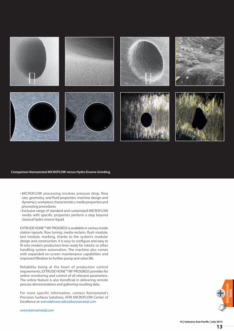
Comparison Kennametal MICROFLOW versus Hydro Erosive Grinding.
10 | Industry Asia Pacific | July 2015
14
N E W SMORE
INFORMATION
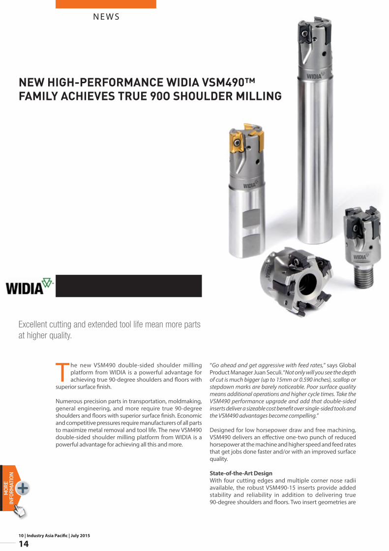
The new VSM490 double-sided shoulder milling platform from WIDIA is a powerful advantage for achieving true 90-degree shoulders and floors with
superior surface finish.
Numerous precision parts in transportation, moldmaking, general engineering, and more require true 90-degree shoulders and floors with superior surface finish. Economic and competitive pressures require manufacturers of all parts to maximize metal removal and tool life. The new VSM490 double-sided shoulder milling platform from WIDIA is a powerful advantage for achieving all this and more.
“Go ahead and get aggressive with feed rates,” says Global Product Manager Juan Seculi. “Not only will you see the depth of cut is much bigger (up to 15mm or 0.590 inches), scallop or stepdown marks are barely noticeable. Poor surface quality means additional operations and higher cycle times. Take the VSM490 performance upgrade and add that double-sided inserts deliver a sizeable cost benefit over single-sided tools and the VSM490 advantages become compelling.”
Designed for low horsepower draw and free machining, VSM490 delivers an effective one-two punch of reduced horsepower at the machine and higher speed and feed rates that get jobs done faster and/or with an improved surface quality.
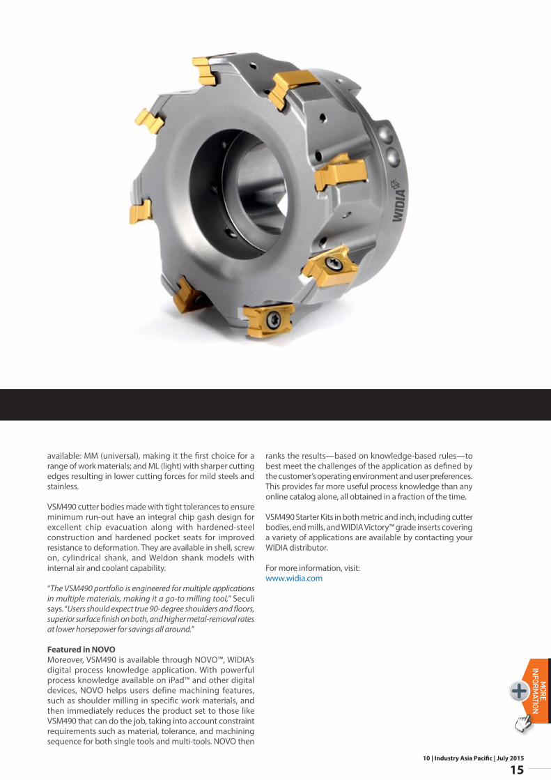
State-of-the-Art DesignWith four cutting edges and multiple corner nose radii available, the robust VSM490-15 inserts provide added stability and reliability in addition to delivering true 90-degree shoulders and floors. Two insert geometries are
Excellent cutting and extended tool life mean more parts at higher quality.
NEW HIGH-PERFORMANCE WIDIA VSM490™ FAMILY ACHIEVES TRUE 90O SHOULDER MILLING
N E W S
10 | Industry Asia Pacific | July 2015
15
MORE
INFORM
ATION
available: MM (universal), making it the first choice for a range of work materials; and ML (light) with sharper cutting edges resulting in lower cutting forces for mild steels and stainless.
VSM490 cutter bodies made with tight tolerances to ensure minimum run-out have an integral chip gash design for excellent chip evacuation along with hardened-steel construction and hardened pocket seats for improved resistance to deformation. They are available in shell, screw on, cylindrical shank, and Weldon shank models with internal air and coolant capability.
“The VSM490 portfolio is engineered for multiple applications in multiple materials, making it a go-to milling tool,” Seculi says. “Users should expect true 90-degree shoulders and floors, superior surface finish on both, and higher metal-removal rates at lower horsepower for savings all around.”
Featured in NOVOMoreover, VSM490 is available through NOVO™, WIDIA’s digital process knowledge application. With powerful process knowledge available on iPad™ and other digital devices, NOVO helps users define machining features, such as shoulder milling in specific work materials, and then immediately reduces the product set to those like VSM490 that can do the job, taking into account constraint requirements such as material, tolerance, and machining sequence for both single tools and multi-tools. NOVO then
ranks the results—based on knowledge-based rules—to best meet the challenges of the application as defined by the customer’s operating environment and user preferences. This provides far more useful process knowledge than any online catalog alone, all obtained in a fraction of the time.
VSM490 Starter Kits in both metric and inch, including cutter bodies, end mills, and WIDIA Victory™ grade inserts covering a variety of applications are available by contacting your WIDIA distributor.
For more information, visit:www.widia.com
10 | Industry Asia Pacific | July 2015
16
N E W SMORE
INFORMATION
The hollow shaft solutions reduce the time and effort for the disassembling of the drive from the customer´s machine shaft, thanks to the new solution with the axial locking ring. The new product solutions make mounting and commissioning easier and faster thanks to the smarter design and allow for easier and more accurate screw tightening.
Furthermore, the cutting-edge design of the shrink disk will improve and speed up set up and commissioning.
The hollow shaft with the two keys at 120° will allow full rated torque and max torque transmissions. The axial locking ring with threaded holes completes the solution for an easier and more reliable shaft mounting. They keyed hollow shaft is available in smaller sizes, ranging from 300 to 310 and will be included in the designation of the series with the acronym “FDK”; when the FZP version is available it will come in larger sizes from 311 to 325.
Bonfiglioli´s 300 Series is a robust and versatile solution perfectly suited for harsh applications where shock loadings and impacts are more the rule than the
exception. It features strong bearings to ensure a long lifespan.
Bonfiglioli´s ongoing mission to improve and innovate their planetary gearboxes for industrial applications has led to two important new features that result in an easier and safer assembling/disassembling of the drive to/from the application. The new FDK and FZP versions feature an output hollow shaft that will make the series more effective and suitable for “shaft mount” assembly.
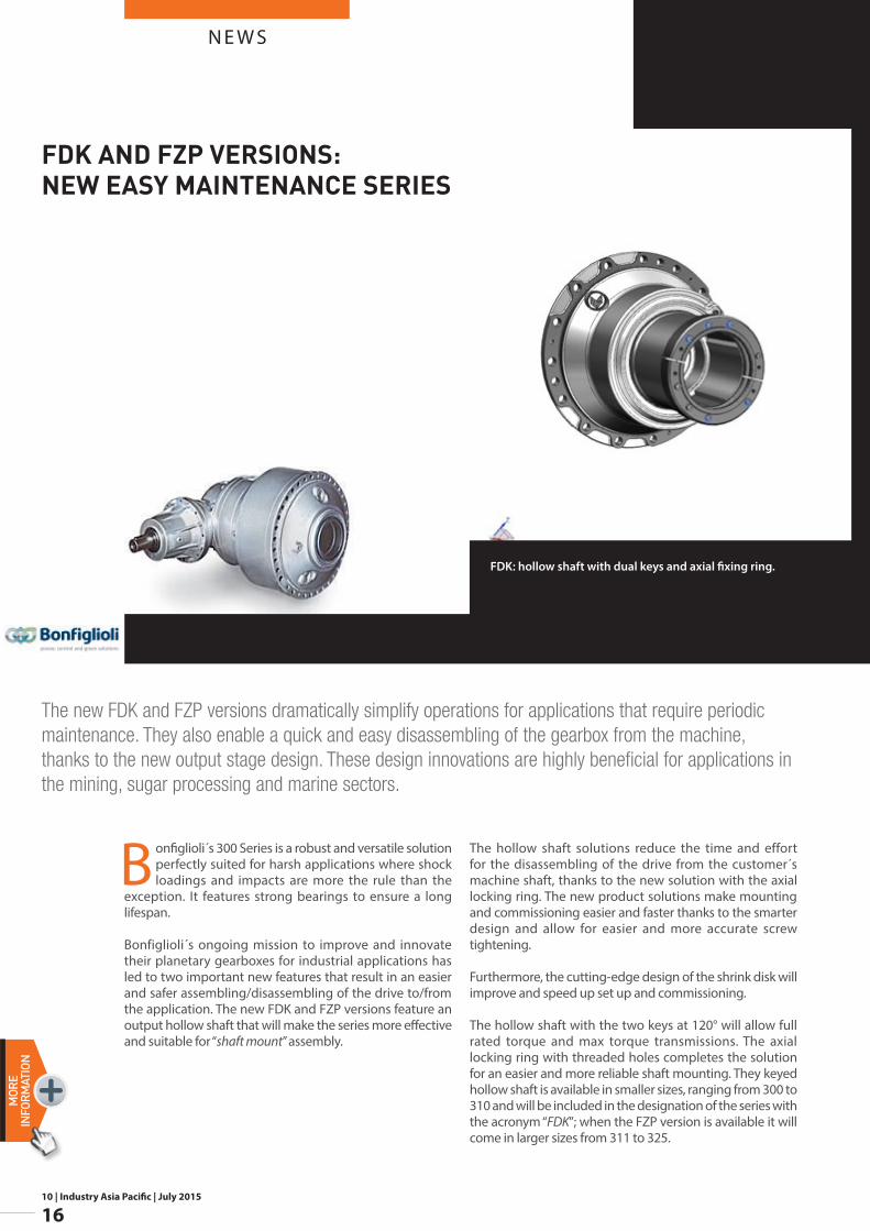
The new FDK and FZP versions dramatically simplify operations for applications that require periodic maintenance. They also enable a quick and easy disassembling of the gearbox from the machine, thanks to the new output stage design. These design innovations are highly beneficial for applications in the mining, sugar processing and marine sectors.
FDK: hollow shaft with dual keys and axial fixing ring.
FDK AND FZP VERSIONS: NEW EASY MAINTENANCE SERIES

N E W S
10 | Industry Asia Pacific | July 2015
17
MORE
INFORM
ATION
Another advanced design component of the new 300 series is the splined hollow shaft which meets the DIN 5480 standard and offers the same strong bearings available in the current FP version. It provides double centering for an aligned assembling of the solid shaft of the machine. Like the keyed hollow shaft, the splined hollow shaft also includes an axial locking key with threaded holes for easier mounting and grants full rated and max torque transmissions.
The new shrink disks prevent accidental mounting errors (even when dismounting and re-mounting the shrink disk) thanks to simpler design and “visual-control” of screw tightening torque.
This advanced design makes the 300 series now complete and effective for any shaft mounted requirements for all sizes and ratios. The series has a torque range of 1,000-1,287 000 Nm and gear ratios of 3.4-5,234.
Bonfiglioli´s new 300 series offers customers a higher quality and more flexible solution due to its ability to adapt to client and application requirements and provides more control during the mounting process. It is also the most compact solution available on the market.
www.bonfiglioli.com
G0A: shrink disk in two parts. FZP: slotted hollow shaft with axial fixing ring.
10 | Industry Asia Pacific | July 2015
18
N E W SMORE
INFORMATION
control of chip thickness are the key elements that lead to achievement of the goal.
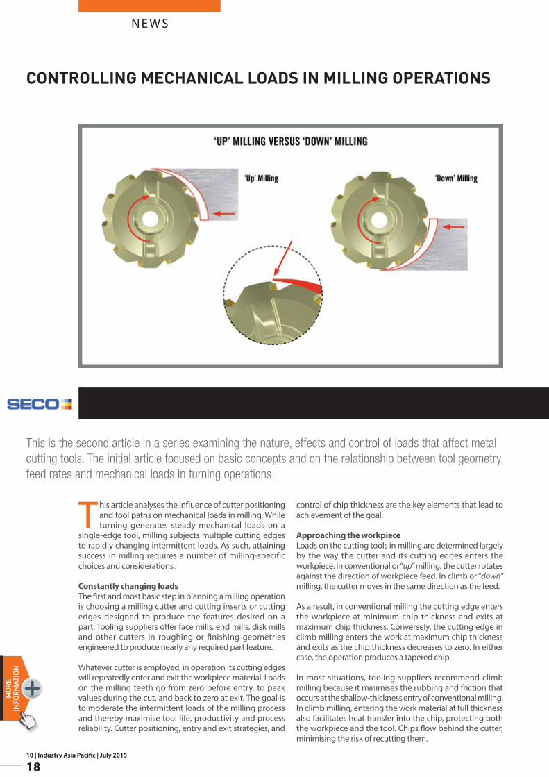
Approaching the workpieceLoads on the cutting tools in milling are determined largely by the way the cutter and its cutting edges enters the workpiece. In conventional or “up” milling, the cutter rotates against the direction of workpiece feed. In climb or “down” milling, the cutter moves in the same direction as the feed.
As a result, in conventional milling the cutting edge enters the workpiece at minimum chip thickness and exits at maximum chip thickness. Conversely, the cutting edge in climb milling enters the work at maximum chip thickness and exits as the chip thickness decreases to zero. In either case, the operation produces a tapered chip.
In most situations, tooling suppliers recommend climb milling because it minimises the rubbing and friction that occurs at the shallow-thickness entry of conventional milling. In climb milling, entering the work material at full thickness also facilitates heat transfer into the chip, protecting both the workpiece and the tool. Chips flow behind the cutter, minimising the risk of recutting them.
This article analyses the influence of cutter positioning and tool paths on mechanical loads in milling. While turning generates steady mechanical loads on a
single-edge tool, milling subjects multiple cutting edges to rapidly changing intermittent loads. As such, attaining success in milling requires a number of milling-specific choices and considerations..
Constantly changing loadsThe first and most basic step in planning a milling operation is choosing a milling cutter and cutting inserts or cutting edges designed to produce the features desired on a part. Tooling suppliers offer face mills, end mills, disk mills and other cutters in roughing or finishing geometries engineered to produce nearly any required part feature.
Whatever cutter is employed, in operation its cutting edges will repeatedly enter and exit the workpiece material. Loads on the milling teeth go from zero before entry, to peak values during the cut, and back to zero at exit. The goal is to moderate the intermittent loads of the milling process and thereby maximise tool life, productivity and process reliability. Cutter positioning, entry and exit strategies, and
This is the second article in a series examining the nature, effects and control of loads that affect metal cutting tools. The initial article focused on basic concepts and on the relationship between tool geometry, feed rates and mechanical loads in turning operations.
CONTROLLING MECHANICAL LOADS IN MILLING OPERATIONS
N E W S
10 | Industry Asia Pacific | July 2015
19
MORE
INFORM
ATION
In some cases, however, conventional milling is preferred. Face milling with the climb method generates downward force that can cause backlash movement on older manual machines. Conventional milling, in which the cutter pulls up on the workpiece, may be a better choice with less-stable machines, especially in heavy cuts. Conventional milling also can be effective when milling rough-surfaced or thin-walled materials, and the gradual entry into the workpiece material can protect brittle super hard cutting tool materials from impact damage. On the other hand, the excessive friction and heat that can occur in the shallow entry characteristic of conventional milling may have detrimental effects on a tool. Uneven force on the tool edge can cause edge chipping and increase tensile stresses. Surface finish may suffer because chips drop in front of the cutter and may be recut.
The full-thickness entry of the cutting tool in climb milling subjects the tool to heavy mechanical loads, but for most cutting tool materials that is not a major problem. Modern tool materials including carbides, ceramics and high-speed steels are powder-based products that have good compressive strength.
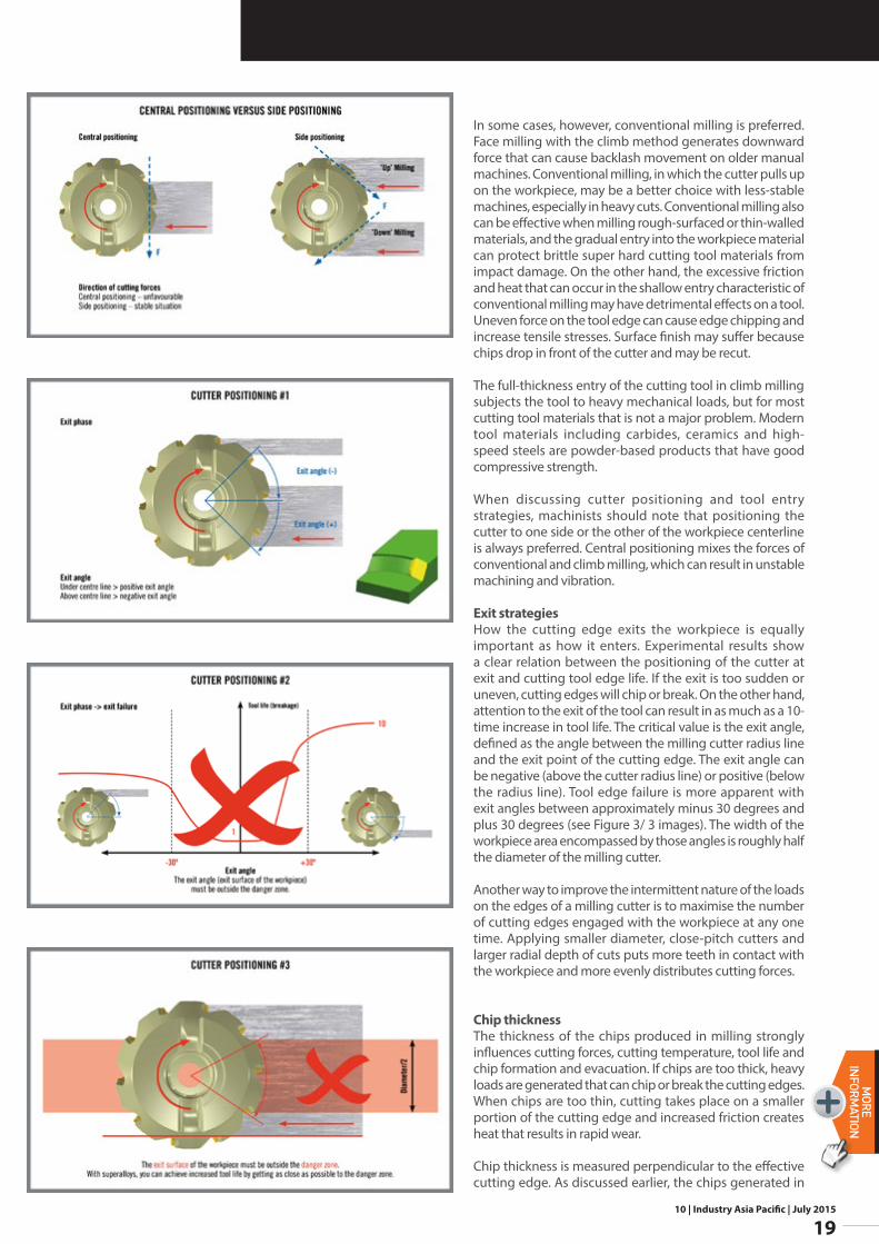
When discussing cutter positioning and tool entry strategies, machinists should note that positioning the cutter to one side or the other of the workpiece centerline is always preferred. Central positioning mixes the forces of conventional and climb milling, which can result in unstable machining and vibration.
Exit strategiesHow the cutting edge exits the workpiece is equally important as how it enters. Experimental results show a clear relation between the positioning of the cutter at exit and cutting tool edge life. If the exit is too sudden or uneven, cutting edges will chip or break. On the other hand, attention to the exit of the tool can result in as much as a 10-time increase in tool life. The critical value is the exit angle, defined as the angle between the milling cutter radius line and the exit point of the cutting edge. The exit angle can be negative (above the cutter radius line) or positive (below the radius line). Tool edge failure is more apparent with exit angles between approximately minus 30 degrees and plus 30 degrees (see Figure 3/ 3 images). The width of the workpiece area encompassed by those angles is roughly half the diameter of the milling cutter.
Another way to improve the intermittent nature of the loads on the edges of a milling cutter is to maximise the number of cutting edges engaged with the workpiece at any one time. Applying smaller diameter, close-pitch cutters and larger radial depth of cuts puts more teeth in contact with the workpiece and more evenly distributes cutting forces.
Chip thicknessThe thickness of the chips produced in milling strongly influences cutting forces, cutting temperature, tool life and chip formation and evacuation. If chips are too thick, heavy loads are generated that can chip or break the cutting edges. When chips are too thin, cutting takes place on a smaller portion of the cutting edge and increased friction creates heat that results in rapid wear.
Chip thickness is measured perpendicular to the effective cutting edge. As discussed earlier, the chips generated in
10 | Industry Asia Pacific | July 2015
20
N E W SMORE
INFORMATION
Machinists can utilise these principles and methods in basic milling applications to control the intermittent stresses on milling tools. However, as part requirements become more complex — even at the level of simply milling into corners — manually changing feed rates to maintain recommended average chip thicknesses is essentially impossible. For those cases and beyond, including very complex 5-axis milling, makers of CAM software and advanced CNC equipment have developed techniques such as trochoidal milling and corner peeling as well as constant tool engagement tool path programs such as Dynamic Milling, Volumill, or Adaptive Clearing. These software and machine control advances represent the high-tech evolution of the basic concepts of management of tool entry, exit, and chip thickness to control the effects of the intermittent milling process on the cutting tool.
Chip thicknessManufacturers have employed milling machines and tools for more than a century, producing countless parts in high volumes and top quality. Over that time, the basic milling process has remained the same, namely the use of a rotating cutter on a workpiece to machine a surface. The intermittent cutting nature of the process has remained the same as well.
Milling machines and milling tooling have evolved to an unbelievable extent, but in many cases their users are not taking full advantage of that technical progress. Recognising the unique interaction of workpiece and tool that takes place in milling and working to moderate the intermittent stresses involved in the process enables manufacturers to achieve the rarely-attainable triple goal of maximum productivity, quality and tool life..
www.secotools.com
By: Patrick de Vos, Corporate Technical Education Manager, Seco Tools
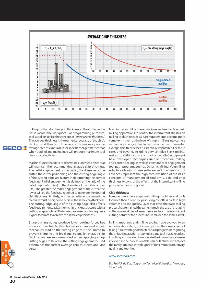
milling continually change in thickness as the cutting edge passes across the workpiece. For programming purposes, tool suppliers utilise the concept of “average chip thickness.” The average thickness is the numerical average of the chip’s thickest and thinnest dimensions. Toolmakers provide average chip thickness data for specific tool geometries that when applied and maintained will produce maximum tool life and productivity.
Machinists use that data to determine cutter feed rates that will maintain the recommended average chip thickness. The radial engagement of the cutter, the diameter of the cutter, the cutter positioning and the cutting edge angle of the cutting edge are factors in determining the correct feed rate. Radial engagement is defined as the ratio of the radial depth of cut (ae) to the diameter of the milling cutter (Dc). The greater the radial engagement of the cutter, the lower will be the feed rate required to generate the desired chip thickness. Similarly, with lesser cutter engagement the feed rate must be higher to achieve the same chip thickness. The cutting edge angle of the cutting edge also affects feed requirements. Maximum chip thickness occurs with a cutting edge angle of 90 degrees, so lesser angles require a higher feed rate to achieve the same chip thickness.
Sharp cutting edges produce lower cutting forces but are also more fragile than honed or chamfered edges. Mechanical load on the cutting edge must be limited to prevent chipping and breakage, so smaller average chip thicknesses are recommended when applying sharp cutting edges. In this case, the cutting edge geometry used determines the correct average chip thickness and vice versa.
10 | Industry Asia Pacific | July 2015
21
N E W SMORE
INFORM
ATION
NORD has always taken a comprehensive approach that considers the entire drive train. All components – gearboxes, motors, power electronics, and functional intelligence are in-house developments manufactured in NORD factories, which makes the company a single-source provider of complete drive solutions for over 100 industries.
The 50-year-old company has gathered extensive application know-how and a detailed understanding of the interaction of all drive components. System efficiency according to EN 50598-2 is not only rated at full power but at eight designated load points with different torques and speeds. Breaking with a long-established concept, the standard does not consider energy efficiency percentiles, but incremental power loss in Watts.
One consequence of this new approach is that system performance in drive scenarios with the motor at standstill and under load (e.g. elevator stop) can now also be compared.
www.nord.com
In the most recent Ecodesign standard EN 50598-2, the European Union is establishing efficiency requirements for drive electronics as well as complete drive systems.
Ahead of any regulations becoming effective, NORD DRIVESYSTEMS is already performing tests and numerical analyses for components and systems manufactured in-house and can therefore quickly provide detailed information to resolve any customer queries concerning the EN 50598-2 standard.
Future requirements can be flexibly fulfilled. The standard defines efficiency classes for frequency inverters and motor starters: IE0 (high losses), IE1 (reference values), and IE2 (losses significantly below reference). Following the same pattern, system efficiency is rated IES0, IES1, and IES2.
Current tests with NORD inverters have shown power losses significantly below the reference values in the EN 50598-2 standard both for the inverters themselves and for power drive systems (PDS) combining inverters and energy-efficient motors. Consequentially, NORD is always able to achieve an IES2 system efficiency rating.
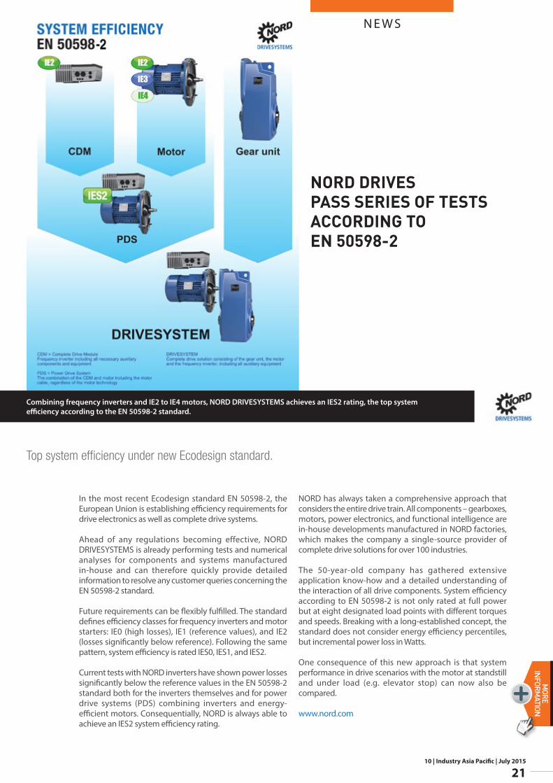
Top system efficiency under new Ecodesign standard.
Combining frequency inverters and IE2 to IE4 motors, NORD DRIVESYSTEMS achieves an IES2 rating, the top system efficiency according to the EN 50598-2 standard.
NORD DRIVES PASS SERIES OF TESTS ACCORDING TO EN 50598-2
10 | Industry Asia Pacific | July 2015
22
N E W SMORE
INFORMATION
With 650 employees, GreyLogix is among the largest experts in designing automation technology solutions. In business for the past fifteen years,
the company specialises in large automation technology projects that require engineering expertise as well as industry-specific know-how. This is why their design teams are organised into various business units that each focus on specific market segments such as oil and gas, food and beverage and the chemical/pharmaceutical industries.
“We don’t have any standard projects, so there is no learning curve either,” says Thomas Besser, Team Leader for the CAE Centre of Excellence. “It makes expertise and experience all the more important.” This applies to programming, which constitutes the majority of the work, but also to electrical design and switchgear cabinet engineering. GreyLogix has always relied on a high degree of automation: “We recognised early on that we have to be strong in project and process management. We want to offer our customers additional value: be smarter and work more intelligently. We’re continually working on this.”
Eplan Engineering Configuration One (EEC One) is a recent addition to the tools that GreyLogix uses for electrical engineering. The software allows schematics to be generated automatically, based on an Excel interface. This requires a specific approach: the engineer enters basic parameters into a table, such as the voltage for instance. Next, he selects components from an individually configured list, such as “75 kW motor,” hits the “configuration” button, and receives the wiring diagrams.
Preliminary work pays offThe diagram still requires individual adjustments, but it offers a good foundation and saves a lot of time. Thomas Besser explains, “You can generate 50 to 60 per cent of the project with the help of this automated design process. Engineers can now use the extra time to tackle creative tasks.” Components and structures must be defined in advance, but the effort pays off, which is why GreyLogix is gradually phasing in EEC One in all of its business units. Engineers have the freedom to use the system as they see fit. “You don’t have to handle everything in EEC One,” Besser says. “For instance, engineers can just as well set up all the device tags in
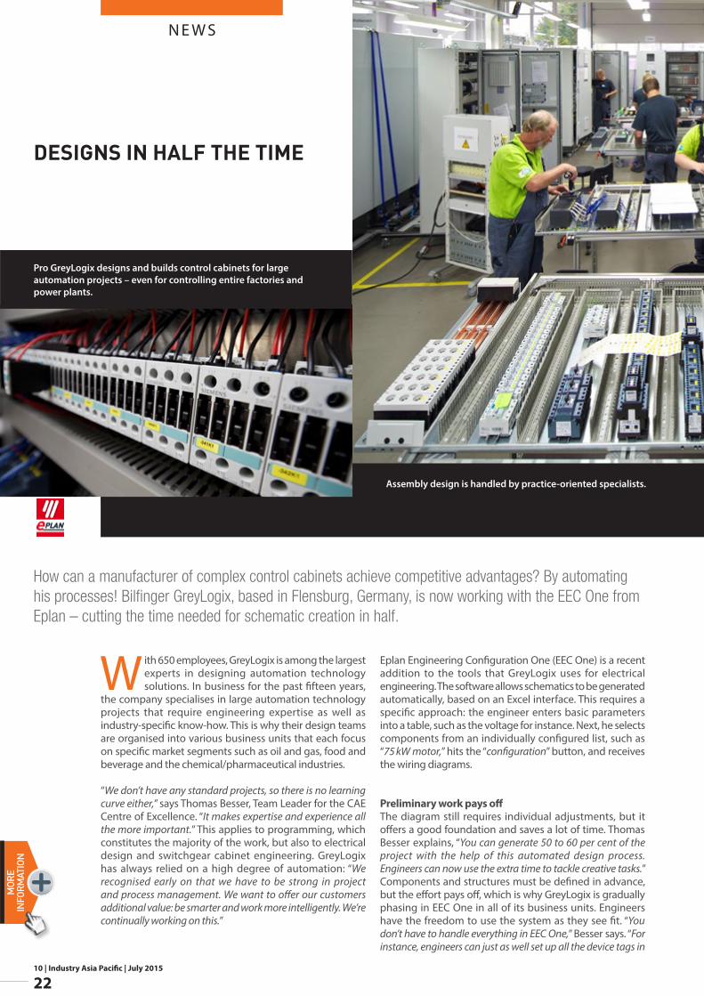
How can a manufacturer of complex control cabinets achieve competitive advantages? By automating his processes! Bilfinger GreyLogix, based in Flensburg, Germany, is now working with the EEC One from Eplan – cutting the time needed for schematic creation in half.
DESIGNS IN HALF THE TIME
Assembly design is handled by practice-oriented specialists.
Pro GreyLogix designs and builds control cabinets for large automation projects – even for controlling entire factories and power plants.
N E W S
10 | Industry Asia Pacific | July 2015
23
MORE
INFORM
ATION
Eplan Electric P8 – it’s their choice.” The advantages GreyLogix sees in automated electrical engineering are so big that the company is currently considering introducing a similar concept for software programming: as Besser notes, “We would be able to shave off an additional 10 to 15 per cent of the hours necessary for this very time-consuming task.”
For control cabinet manufacturing, GreyLogix does this without a warehouse. The available components are assembled according to the Kanban system. As the components run through the production process, each control cabinet panel is placed on a specially built assembly cart, which enhances flexibility. A large planning board at the front of the hall displays the current cycles in which the individual products are structured and work stations are staffed. Automation is well advanced here, too: sheet metal processing is performed directly from the CAE system – Eplan Pro Panel – on a Perforex machining centre from Kiesling.
Assembly design of control cabinets using Eplan Pro Panel is carried out by experts who are solely responsible for this task. “The three colleagues originally worked in production,” Besser says. “They know how assembly is done best. The engineers turn over the designs and are also responsible for initiating orders and printing out the wiring diagrams.” Both the customers and the sales department appreciate the 3D layouts generated in Eplan Pro Panel. GreyLogix follows the wishes of its customers in selecting the engineering tool:
“We use nine different ECAD programs. But when we decide for ourselves which program we use, we choose Eplan. Assembly design however is always done in Eplan.”
www.eplan.com.my
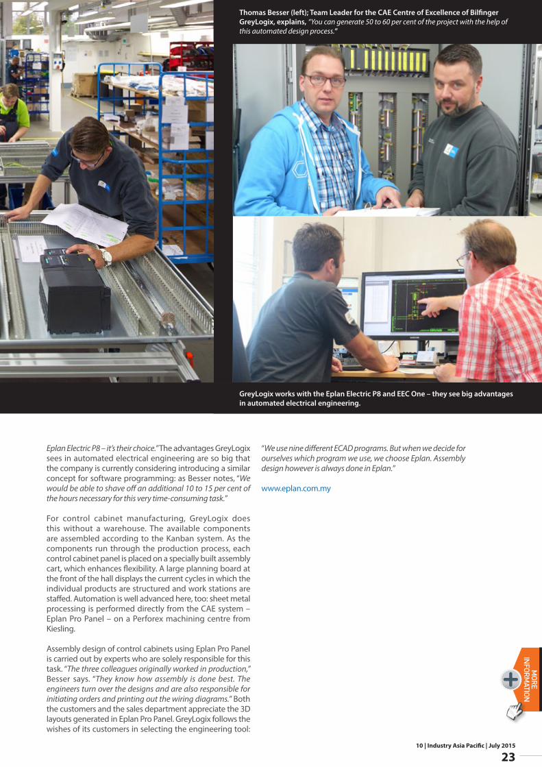
GreyLogix works with the Eplan Electric P8 and EEC One – they see big advantages in automated electrical engineering.
Thomas Besser (left); Team Leader for the CAE Centre of Excellence of Bilfinger GreyLogix, explains, “You can generate 50 to 60 per cent of the project with the help of this automated design process.”
10 | Industry Asia Pacific | July 2015
24
N E W SMORE
INFORMATION
which is mounted at a suitable place on the machine, serves as the shot counter. Both not only ensure that assignment of the molds is unmistakable, but they also return the objective database for condition-based maintenance. This extends the service lives and improves reliability during operation, while also increasing the productivity of the systems and improving their efficiency.The SmartLight provides direct feedback regarding the current status of the mold to the operators at the machine. The limit values for “Warning”or “Maintenance required” can be individually defined for each mold. The SmartLight displays the status so that it is visible from a great distance and, most importantly, unmistakable.
The best part: All Mold ID systems can be connected to the control level, an ERP system or an MES system via web services by means of LAN, Wi-Fi or Powerline. The result is access to the data and the processes from everywhere. As a result, Mold ID is a clear and practical example for how Industry 4.0 easily finds its way into production.
www.balluff.co.in
However, these are not always accessible. Therefore, in many cases, maintenance and inspections are frequently carried out only if the produced
components no longer meet the required standards or if the mold malfunctions. This results in unscheduled stoppages that waste plenty of time and money.
This is where Mold ID from Balluff comes in. It supports condition-based maintenance and provides more transparency in mold handling.
By means of industrial RFID, Mold ID makes the use of injection molds traceable and ensures their optimal utilization. The best part: Mold ID is backed by an autonomous system that can be retrofitted anywhere and at any time on all machines, without the need for the manufacturer or intervention in the controller.
In addition to the mold identity, a rugged RFID data carrier at each mold stores the current shot count and various mold-specific process parameters in non-volatile memory without making contact. This data can be called up via a smartphone or a mobile RFID reader at any time (for an audit, for example). An externally attached inductive or optical sensor,
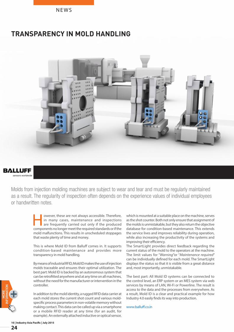
Molds from injection molding machines are subject to wear and tear and must be regularly maintained as a result. The regularity of inspection often depends on the experience values of individual employees or handwritten notes.
TRANSPARENCY IN MOLD HANDLING
10 | Industry Asia Pacific | July 2015
25
N E W SMORE
INFORM
ATION
The IOs are displayed and diagnostics are performed centrally by means of backlit numbers. There is no need to assign labels to LEDs. This setup also ensures that information can be read even in dark conditions. Dual LEDs are used to indicate overload of an output on a channel-specific basis.
The terminal contacts for AS-i and AUX, which are bridged internally, achieve the full 8A, eliminating the need for double wire end ferrules at terminal points.
The sensor supply for the module can easily be switched between an internal supply from AS-i and an external supply through AUX. This reduces the range of devices required.
As a result of the reliable functional isolation between AS-i and AUX, decentralized system components can be safely deactivated using these modules by disabling AUX. This saves on costs and increases plant availability.
For those wanting increased efficiency when it comes to AS-Interface in the switch cabinet, the KE5 is the solution to choose.
www.pepperl-fuchs.com
The push-in connection at the front and individual plug-in terminals make installation quicker and easier.Clear display of active IOs using luminous digits. Clear
function assignment in the cover and still all LED displays remain visible.
Pepperl+Fuchs is setting a new and innovative standard for AS-Interface IP20 modules in the form of an easily accessible push-in connection at the front of the device. The crimped wire ends can be inserted directly into the push-in terminals.
The entire wiring harness is guided downward, meaning there is no need for the upper cable ridge/cable duct. This not only provides a sophisticated solution for the switch cabinet wiring, but also saves on space and ensures clarity. In switch boxes, modules featuring this connection can be mounted flush on the upper edge of a switch box, without impairing the installation.
The transparent hinged cover, which can be snapped into place at multiple points, ensures a clear view through to the digit display at all times and enables the terminal functions to be color-coded internally. The terminals can be removed individually and are coded to prevent them from being mixed up, meaning devices can be replaced without any problems.
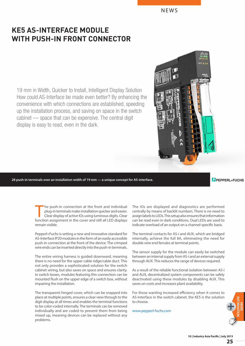
19 mm in Width, Quicker to Install, Intelligent Display Solution How could AS-Interface be made even better? By enhancing the convenience with which connections are established, speeding up the installation process, and saving on space in the switch cabinet — space that can be expensive. The central digit display is easy to read, even in the dark.
28 push-in terminals over an installation width of 19 mm — a unique concept for AS-interface.
KE5 AS-INTERFACE MODULE WITH PUSH-IN FRONT CONNECTOR
10 | Industry Asia Pacific | July 2015
26
N E W SMORE
INFORMATION
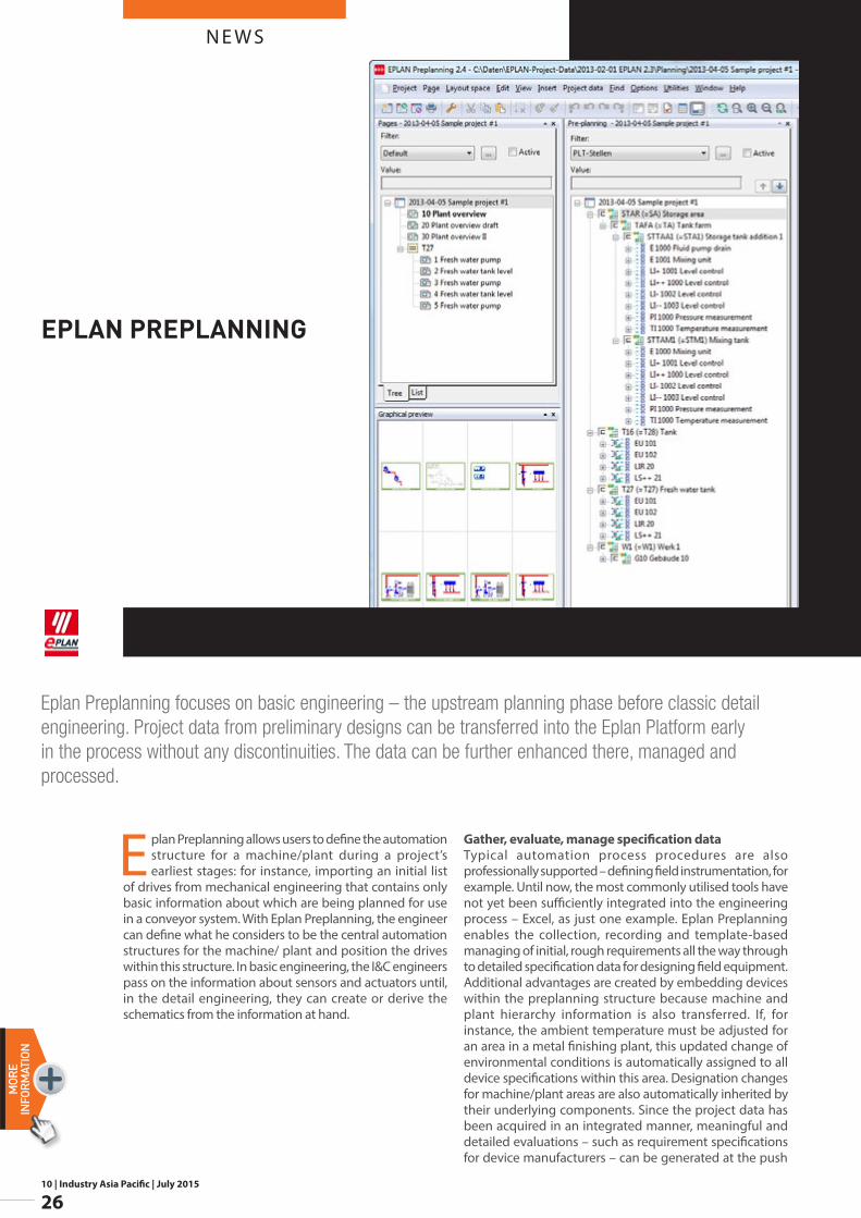
Eplan Preplanning allows users to define the automation structure for a machine/plant during a project’s earliest stages: for instance, importing an initial list
of drives from mechanical engineering that contains only basic information about which are being planned for use in a conveyor system. With Eplan Preplanning, the engineer can define what he considers to be the central automation structures for the machine/ plant and position the drives within this structure. In basic engineering, the I&C engineers pass on the information about sensors and actuators until, in the detail engineering, they can create or derive the schematics from the information at hand.
Gather, evaluate, manage specification dataTypical automation process procedures are also professionally supported – defining field instrumentation, for example. Until now, the most commonly utilised tools have not yet been sufficiently integrated into the engineering process – Excel, as just one example. Eplan Preplanning enables the collection, recording and template-based managing of initial, rough requirements all the way through to detailed specification data for designing field equipment. Additional advantages are created by embedding devices within the preplanning structure because machine and plant hierarchy information is also transferred. If, for instance, the ambient temperature must be adjusted for an area in a metal finishing plant, this updated change of environmental conditions is automatically assigned to all device specifications within this area. Designation changes for machine/plant areas are also automatically inherited by their underlying components. Since the project data has been acquired in an integrated manner, meaningful and detailed evaluations – such as requirement specifications for device manufacturers – can be generated at the push
Eplan Preplanning focuses on basic engineering – the upstream planning phase before classic detail engineering. Project data from preliminary designs can be transferred into the Eplan Platform early in the process without any discontinuities. The data can be further enhanced there, managed and processed.
EPLAN PREPLANNING
N E W S
10 | Industry Asia Pacific | July 2015
27
MORE
INFORM
ATION
of a button. Based on this documentation, the appropriate device technology will be selected further along in the engineering process, and will be stored in the project as a defined component with the corresponding supplementary device data.
Uniform nomenclature simplifies templatesDue to the comprehensive possibilities for configuration, Eplan Preplanning allows users to customise the working environment to their own needs. So-called segment definitions serve as established identifiers for the individual structural levels. Whether the structural levels are for production lines, sections of conveyor systems or tank areas: the matching nomenclature is systematically stored in the templates, which simplifies handling of these structural objects. The same principle holds for planning objects – all the way down to the properties. When importing a list of motors from mechanical engineering, there is a 1:1 mapping of the delivered properties and information onto the device types. For an I&C design task, Eplan Preplanning allows the creation of various measurement-point types that can easily be added to the machine/plant structures via drag & drop. Users decide whether certain properties should be entered as a reference or as a specific measurement point. Referenced properties can quickly be changed across entire projects via centralised template management. This working method is advantageous, especially in a project’s early phases, when fundamental principles for tank level measurement (of tuning forks, impellers or even continual measurement)
might vary due to changing customer requests. This allows a determination of the number of field devices required along with the necessary automation components, or calculation of initial rough cost estimates.
www.eplan.com.my
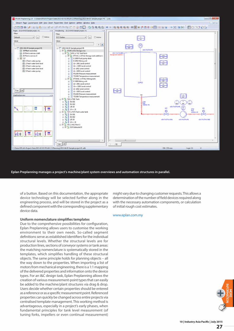
Eplan Preplanning manages a project's machine/plant system overviews and automation structures in parallel.
10 | Industry Asia Pacific | July 2015
28
N E W SMORE
INFORMATION
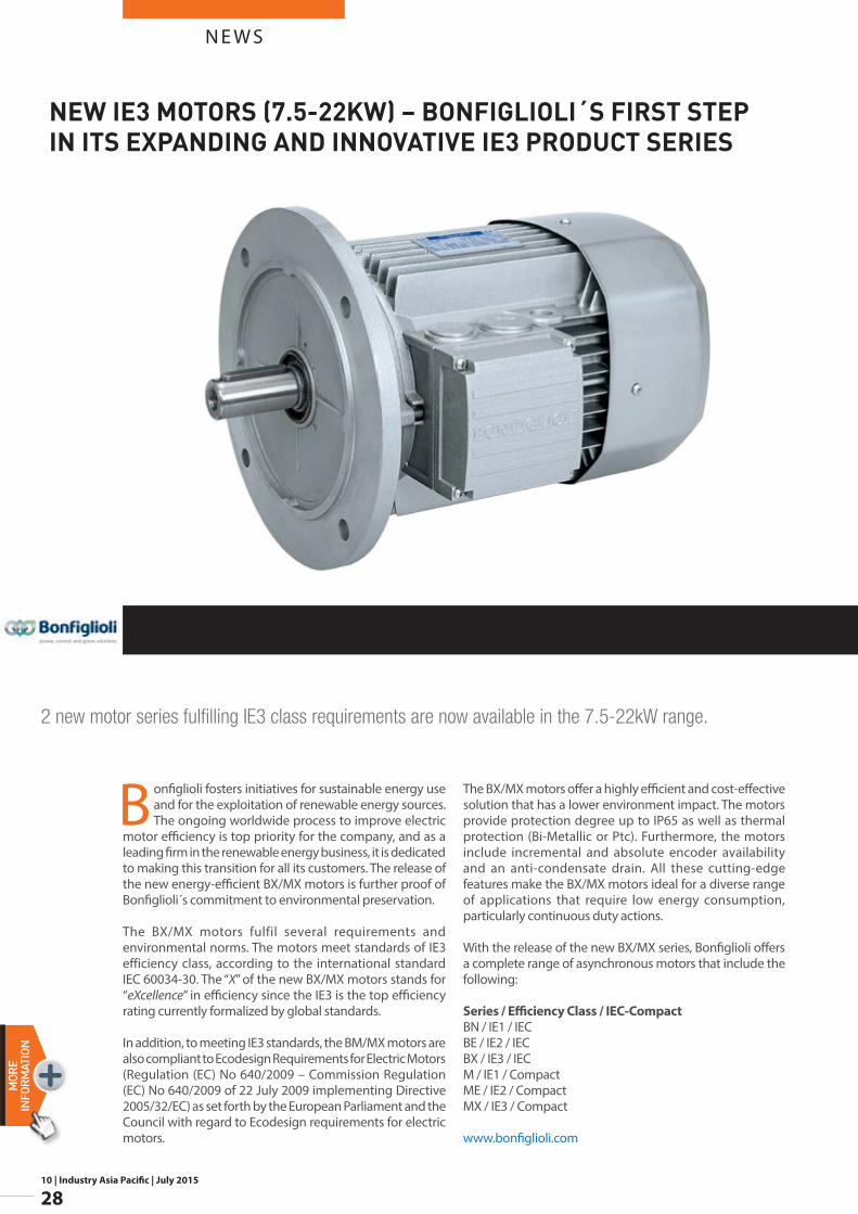
Bonfiglioli fosters initiatives for sustainable energy use and for the exploitation of renewable energy sources. The ongoing worldwide process to improve electric
motor efficiency is top priority for the company, and as a leading firm in the renewable energy business, it is dedicated to making this transition for all its customers. The release of the new energy-efficient BX/MX motors is further proof of Bonfiglioli´s commitment to environmental preservation.
The BX/MX motors fulfil several requirements and environmental norms. The motors meet standards of IE3 efficiency class, according to the international standard IEC 60034-30. The “X” of the new BX/MX motors stands for “eXcellence” in efficiency since the IE3 is the top efficiency rating currently formalized by global standards.
In addition, to meeting IE3 standards, the BM/MX motors are also compliant to Ecodesign Requirements for Electric Motors (Regulation (EC) No 640/2009 – Commission Regulation (EC) No 640/2009 of 22 July 2009 implementing Directive 2005/32/EC) as set forth by the European Parliament and the Council with regard to Ecodesign requirements for electric motors.
The BX/MX motors offer a highly efficient and cost-effective solution that has a lower environment impact. The motors provide protection degree up to IP65 as well as thermal protection (Bi-Metallic or Ptc). Furthermore, the motors include incremental and absolute encoder availability and an anti-condensate drain. All these cutting-edge features make the BX/MX motors ideal for a diverse range of applications that require low energy consumption, particularly continuous duty actions.
With the release of the new BX/MX series, Bonfiglioli offers a complete range of asynchronous motors that include the following:
Series / Efficiency Class / IEC-CompactBN / IE1 / IECBE / IE2 / IECBX / IE3 / IECM / IE1 / CompactME / IE2 / CompactMX / IE3 / Compact
www.bonfiglioli.com
2 new motor series fulfilling IE3 class requirements are now available in the 7.5-22kW range.
NEW IE3 MOTORS (7.5-22KW) – BONFIGLIOLI´S FIRST STEP IN ITS EXPANDING AND INNOVATIVE IE3 PRODUCT SERIES
10 | Industry Asia Pacific | July 2015
29
N E W SMORE
INFORM
ATION
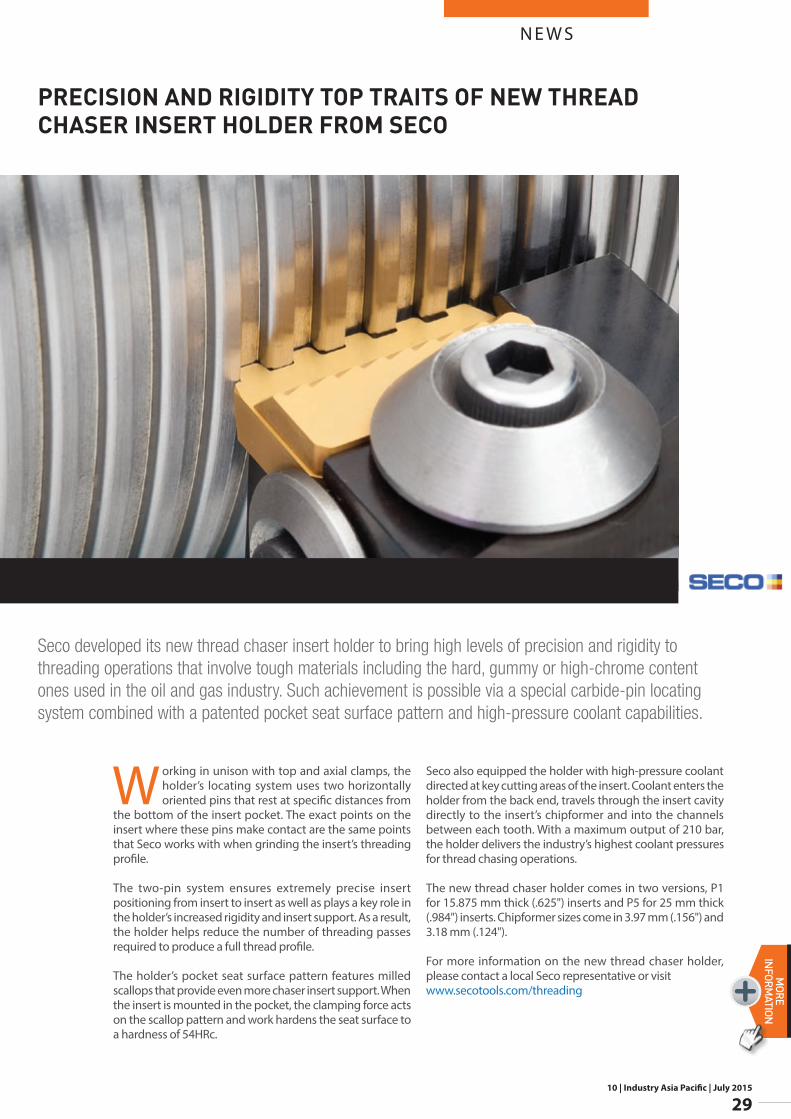
Working in unison with top and axial clamps, the holder’s locating system uses two horizontally oriented pins that rest at specific distances from
the bottom of the insert pocket. The exact points on the insert where these pins make contact are the same points that Seco works with when grinding the insert’s threading profile.
The two-pin system ensures extremely precise insert positioning from insert to insert as well as plays a key role in the holder’s increased rigidity and insert support. As a result, the holder helps reduce the number of threading passes required to produce a full thread profile.
The holder’s pocket seat surface pattern features milled scallops that provide even more chaser insert support. When the insert is mounted in the pocket, the clamping force acts on the scallop pattern and work hardens the seat surface to a hardness of 54HRc.
Seco also equipped the holder with high-pressure coolant directed at key cutting areas of the insert. Coolant enters the holder from the back end, travels through the insert cavity directly to the insert’s chipformer and into the channels between each tooth. With a maximum output of 210 bar, the holder delivers the industry’s highest coolant pressures for thread chasing operations.
The new thread chaser holder comes in two versions, P1 for 15.875 mm thick (.625") inserts and P5 for 25 mm thick (.984") inserts. Chipformer sizes come in 3.97 mm (.156") and 3.18 mm (.124").
For more information on the new thread chaser holder, please contact a local Seco representative or visit www.secotools.com/threading
Seco developed its new thread chaser insert holder to bring high levels of precision and rigidity to threading operations that involve tough materials including the hard, gummy or high-chrome content ones used in the oil and gas industry. Such achievement is possible via a special carbide-pin locating system combined with a patented pocket seat surface pattern and high-pressure coolant capabilities.
PRECISION AND RIGIDITY TOP TRAITS OF NEW THREAD CHASER INSERT HOLDER FROM SECO
10 | Industry Asia Pacific | July 2015
30
N E W SMORE
INFORMATION
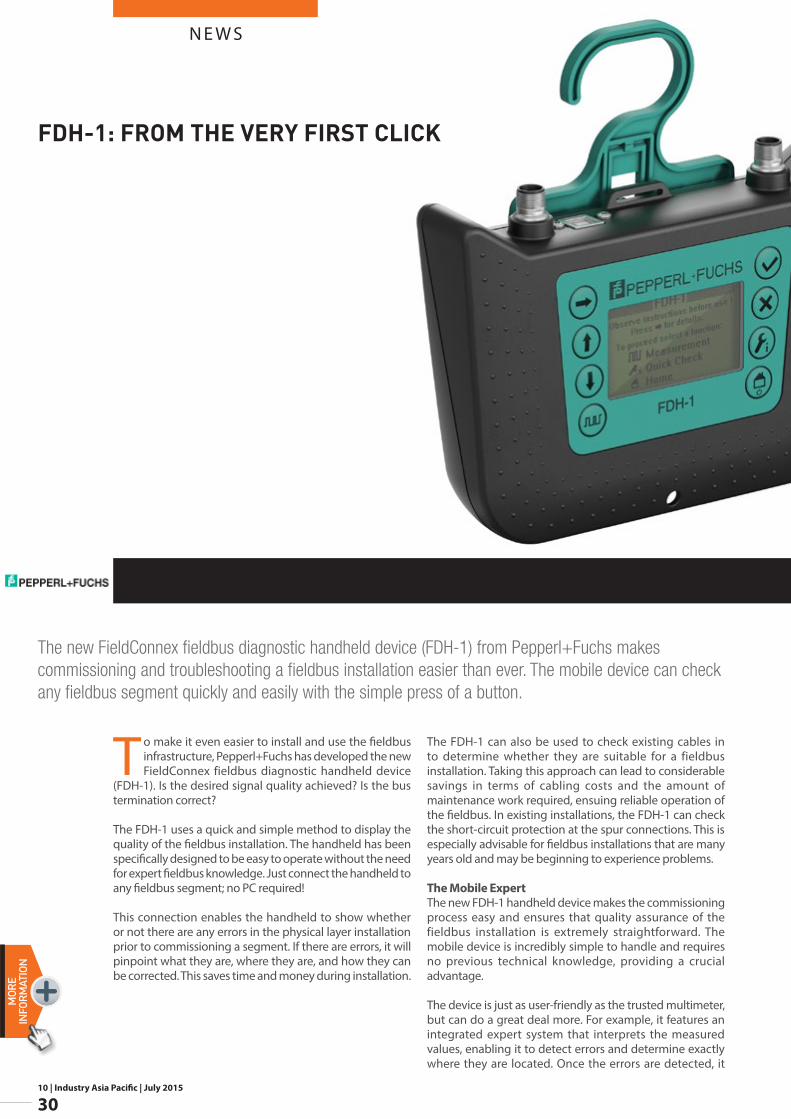
To make it even easier to install and use the fieldbus infrastructure, Pepperl+Fuchs has developed the new FieldConnex fieldbus diagnostic handheld device
(FDH-1). Is the desired signal quality achieved? Is the bus termination correct?
The FDH-1 uses a quick and simple method to display the quality of the fieldbus installation. The handheld has been specifically designed to be easy to operate without the need for expert fieldbus knowledge. Just connect the handheld to any fieldbus segment; no PC required!
This connection enables the handheld to show whether or not there are any errors in the physical layer installation prior to commissioning a segment. If there are errors, it will pinpoint what they are, where they are, and how they can be corrected. This saves time and money during installation.
The FDH-1 can also be used to check existing cables in to determine whether they are suitable for a fieldbus installation. Taking this approach can lead to considerable savings in terms of cabling costs and the amount of maintenance work required, ensuing reliable operation of the fieldbus. In existing installations, the FDH-1 can check the short-circuit protection at the spur connections. This is especially advisable for fieldbus installations that are many years old and may be beginning to experience problems.
The Mobile ExpertThe new FDH-1 handheld device makes the commissioning process easy and ensures that quality assurance of the fieldbus installation is extremely straightforward. The mobile device is incredibly simple to handle and requires no previous technical knowledge, providing a crucial advantage.
The device is just as user-friendly as the trusted multimeter, but can do a great deal more. For example, it features an integrated expert system that interprets the measured values, enabling it to detect errors and determine exactly where they are located. Once the errors are detected, it
The new FieldConnex fieldbus diagnostic handheld device (FDH-1) from Pepperl+Fuchs makes commissioning and troubleshooting a fieldbus installation easier than ever. The mobile device can check any fieldbus segment quickly and easily with the simple press of a button.
FDH-1: FROM THE VERY FIRST CLICK
N E W S
10 | Industry Asia Pacific | July 2015
31
MORE
INFORM
ATION
will also provide a simple corrective action statement. In addition to this expert system, a commissioning wizard with guided dialogs ensures the handheld device is easy to use.
The wizard compares the installation to values set from fieldbus standards and specifications, enabling a target/actual comparison. If required, the wizard can create documentation in a storage format that can be downloaded via USB. The test report can also simply be downloaded again at a later date and used for comparison measurements.
The new FieldConnex fieldbus diagnostic handheld device from Pepperl+Fuchs makes the fieldbus installation as easy and straightforward as possible, providing the ideal basis for trouble-free operation and maximum availability of processing equipment. The FDH-1 is approved for use in all hazardous areas and for all types of explosion protection.
The data sheet and additional application examples can be found at: www.pepperl-fuchs.com
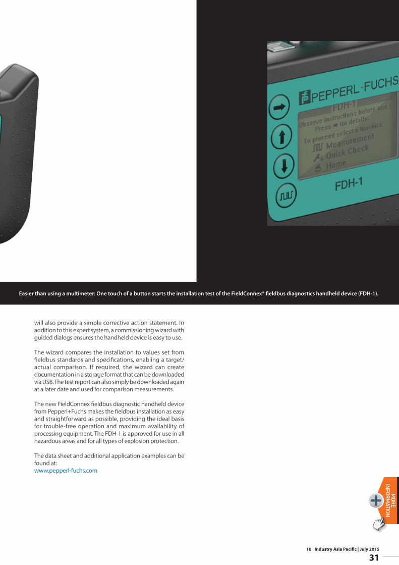
Easier than using a multimeter: One touch of a button starts the installation test of the FieldConnex® fieldbus diagnostics handheld device (FDH-1).

10 | Industry Asia Pacific | July 2015
32
N E W SMORE
INFORMATION
Picture (from left to right): Sascha Engel, Director Sales & Marketing Process Instrumentation and Managing Director Baumer Middle East FZE,Mazin S. Al-Alyan, Business Development Manager at Saad M. Al-Alyan Est,Samar K. Al-Rammah, Administration and Finance ManagerSaad M. Al-Alyan, Owner/ General Manager and Oliver Vietze, CEO Baumer Group, look forward to a fruitful cooperation
The company Saad M. Alyan Trading Est., a long-year Baumer distribution partner, now assumes in-country production of mechanical manometers of the Original
Bourdon brand.
“We now are in a position to provide our customers with high-quality products straight from local manufacture”, explains Mr. Sascha Engel, Director Sales & Marketing Process Instrumentation and initiator of the Baumer local content partnership. “Bourdon is one of the most reputed global brands in mechanical process instrumentation, particularly in the Near East. Driving the brand forward by new strategic ideas is therefore just a logical consequence”, says Mr. Saad M. Al-Alyan, CEO of Saad M. Alyan Trading.
The local content agreement in Saudi Arabia comprises the value chain from assembly to calibration of the mechanical manometers. Coming under the process flow of Baumer traceability, shortly “BTrace”, the unique order fulfilment system developed by Baumer, the products meet the very high market requirements in terms of process safety and reliability. Baumer ensures full traceability and complete process documentation throughout the entire manometer production. “We do not compromise on quality and utilize cutting-edge technologies”, underline both Mr. Saad M. Al-Alyan and Mr. Sascha Engel.
The city of Damman is the venue for production ramp-up of the local content installation which will be further expanded by a second operating stage. Preparations for the necessary infrastructure have already begun in order to manufacture the “Original Bourdon” products in most modern ambiance.
Learn more at: www.baumer.com/bourdon
Baumer keeps on pushing internationalization of their brand “Original Bourdon” in the process instrumentation industry. To meet the requiremens of an in-country value program in the Gulf region, Baumer concluded their first local content agreement in Saudi Arabia.
“ORIGINAL BOURDON”: BAUMER VENTURES INTO LOCAL CONTENT PARTNERSHIP IN SAUDI ARABIA
10 | Industry Asia Pacific | July 2015
33
N E W SMORE
INFORM
ATION
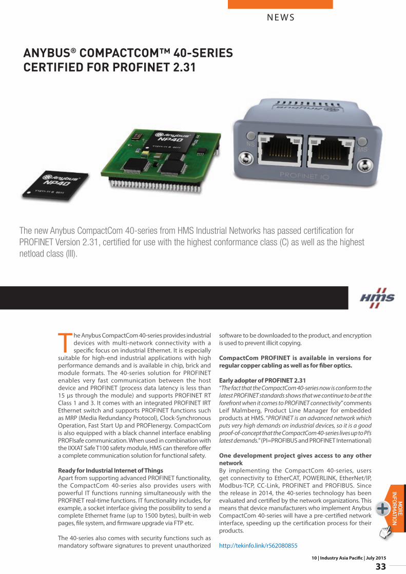
The Anybus CompactCom 40-series provides industrial devices with multi-network connectivity with a specific focus on industrial Ethernet. It is especially
suitable for high-end industrial applications with high performance demands and is available in chip, brick and module formats. The 40-series solution for PROFINET enables very fast communication between the host device and PROFINET (process data latency is less than 15 µs through the module) and supports PROFINET RT Class 1 and 3. It comes with an integrated PROFINET IRT Ethernet switch and supports PROFINET functions such as MRP (Media Redundancy Protocol), Clock-Synchronous Operation, Fast Start Up and PROFIenergy. CompactCom is also equipped with a black channel interface enabling PROFIsafe communication. When used in combination with the IXXAT Safe T100 safety module, HMS can therefore offer a complete communication solution for functional safety.
Ready for Industrial Internet of ThingsApart from supporting advanced PROFINET functionality, the CompactCom 40-series also provides users with powerful IT functions running simultaneously with the PROFINET real-time functions. IT functionality includes, for example, a socket interface giving the possibility to send a complete Ethernet frame (up to 1500 bytes), built-in web pages, file system, and firmware upgrade via FTP etc.
The 40-series also comes with security functions such as mandatory software signatures to prevent unauthorized
software to be downloaded to the product, and encryption is used to prevent illicit copying.
CompactCom PROFINET is available in versions for regular copper cabling as well as for fiber optics.
Early adopter of PROFINET 2.31“The fact that the CompactCom 40-series now is conform to the latest PROFINET standards shows that we continue to be at the forefront when it comes to PROFINET connectivity” comments Leif Malmberg, Product Line Manager for embedded products at HMS. “PROFINET is an advanced network which puts very high demands on industrial devices, so it is a good proof-of-concept that the CompactCom 40-series lives up to PI’s latest demands.” (PI=PROFIBUS and PROFINET International)
One development project gives access to any other networkBy implementing the CompactCom 40-series, users get connectivity to EtherCAT, POWERLINK, EtherNet/IP, Modbus-TCP, CC-Link, PROFINET and PROFIBUS. Since the release in 2014, the 40-series technology has been evaluated and certified by the network organizations. This means that device manufacturers who implement Anybus CompactCom 40-series will have a pre-certified network interface, speeding up the certification process for their products.
http://tekinfo.link/r562080855
The new Anybus CompactCom 40-series from HMS Industrial Networks has passed certification for PROFINET Version 2.31, certified for use with the highest conformance class (C) as well as the highest netload class (III).
ANYBUS® COMPACTCOM™ 40-SERIES CERTIFIED FOR PROFINET 2.31
10 | Industry Asia Pacific | July 2015
34
N E W SMORE
INFORMATION
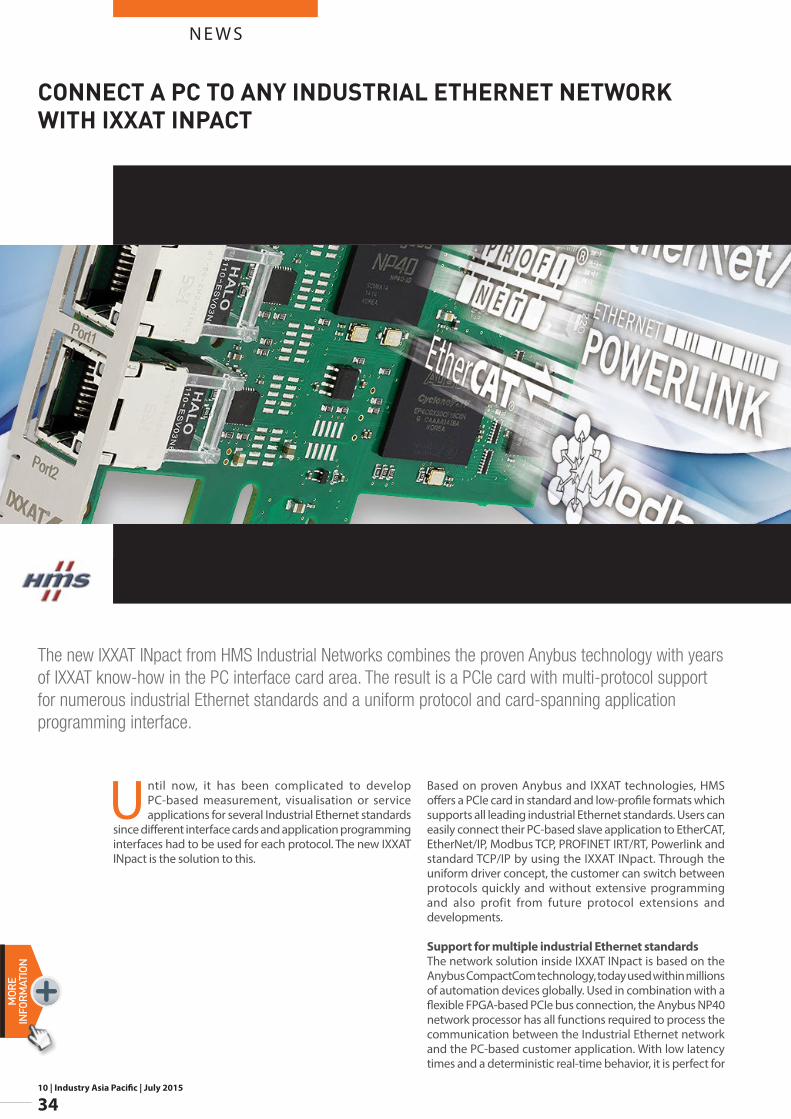
Until now, it has been complicated to develop PC-based measurement, visualisation or service applications for several Industrial Ethernet standards
since different interface cards and application programming interfaces had to be used for each protocol. The new IXXAT INpact is the solution to this.
Based on proven Anybus and IXXAT technologies, HMS offers a PCIe card in standard and low-profile formats which supports all leading industrial Ethernet standards. Users can easily connect their PC-based slave application to EtherCAT, EtherNet/IP, Modbus TCP, PROFINET IRT/RT, Powerlink and standard TCP/IP by using the IXXAT INpact. Through the uniform driver concept, the customer can switch between protocols quickly and without extensive programming and also profit from future protocol extensions and developments.
Support for multiple industrial Ethernet standardsThe network solution inside IXXAT INpact is based on the Anybus CompactCom technology, today used within millions of automation devices globally. Used in combination with a flexible FPGA-based PCIe bus connection, the Anybus NP40 network processor has all functions required to process the communication between the Industrial Ethernet network and the PC-based customer application. With low latency times and a deterministic real-time behavior, it is perfect for
The new IXXAT INpact from HMS Industrial Networks combines the proven Anybus technology with years of IXXAT know-how in the PC interface card area. The result is a PCIe card with multi-protocol support for numerous industrial Ethernet standards and a uniform protocol and card-spanning application programming interface.
CONNECT A PC TO ANY INDUSTRIAL ETHERNET NETWORK WITH IXXAT INPACT
N E W S
10 | Industry Asia Pacific | July 2015
35
MORE
INFORM
ATION
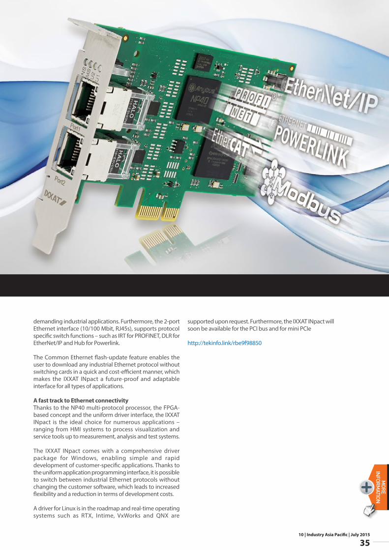
demanding industrial applications. Furthermore, the 2-port Ethernet interface (10/100 Mbit, RJ45s), supports protocol specific switch functions – such as IRT for PROFINET, DLR for EtherNet/IP and Hub for Powerlink.
The Common Ethernet flash-update feature enables the user to download any industrial Ethernet protocol without switching cards in a quick and cost-efficient manner, which makes the IXXAT INpact a future-proof and adaptable interface for all types of applications.
A fast track to Ethernet connectivityThanks to the NP40 multi-protocol processor, the FPGA-based concept and the uniform driver interface, the IXXAT INpact is the ideal choice for numerous applications – ranging from HMI systems to process visualization and service tools up to measurement, analysis and test systems.
The IXXAT INpact comes with a comprehensive driver package for Windows, enabling simple and rapid development of customer-specific applications. Thanks to the uniform application programming interface, it is possible to switch between industrial Ethernet protocols without changing the customer software, which leads to increased flexibility and a reduction in terms of development costs.
A driver for Linux is in the roadmap and real-time operating systems such as RTX, Intime, VxWorks and QNX are
supported upon request. Furthermore, the IXXAT INpact will soon be available for the PCI bus and for mini PCIe
http://tekinfo.link/rbe9f98850