industrial shaft seals - skf · 2020-06-19 · catalogue skf provides this catalogue in electronic...
TRANSCRIPT

Industrial shaft seals

self-adhesive transparent business card pocketmeasurements tbd
Unit conversions
Quantity Unit Conversion
Length 1 mm inch 0.039 in 1 in 25,40 mm
1 m foot 3.281 ft 1 ft 0,3048 m
1 m yard 1.094 yd 1 yd 0,9144 m
1 km mile 0.6214 mile 1 mile 1,609 km
Velocity, speed 1 m/s foot per second 3.28 ft/s 1 ft/s 0,30480 m/s
1 m/s foot per minute 196.8504 ft/min 1 ft/min 0,00508 m/s
1 km/h mile per hour 0.6214 mile/h(mph)
1 mile/h(mph)
1,609 km/h
Force 1 N pound-force 0.225 lbf 1 lbf 4,4482 N
Pressure, stress 1 MPa pounds per square inch 145 psi 1 psi 6,8948 × 10³ Pa
Temperature Celsius ° (degree) tC = 0,555 (tF – 32) Fahrenheit tF = 1,8 tC + 32
22

SKF mobile app
SKF Seal Select is an online seal and accessory selection tool.
Through several different input parameters you can easily ind a
suitable SKF sealing solution for a speciic application. SKF Seal
Select currently offers a selection tool for:
• SKF Speedi-Sleeve
• V-ring seals
• Radial shaft seals
This catalogue as PDF To download a PDF document of this catalogue and for information
about important updates, go to skf.com/go/18729. Please note
product data in this printed catalogue was accurate on the day of
printing. The latest and most accurate product data is always availa-
ble for you on skf.com.
SKF online
Visit the oficial Website skf.com or for discussion the forum and
blog on http://industrialsealsexpert.skf.com/
Find a distributor or a SKF facility online
1 Fill in your city, state and / or postal zip code below to ind an SKF
distributor near you
2 You can ilter your search further by using the drop-down choices
on the right, please select Power Transmission Seals!
3 Your results will show on the bottom right If you prefer to search by
list, go to Find a distributor by list.
Apple App Store
Website Forum and Blog
Find SKFFind a distributor
Catalogue as PDF
33

Contents . . . . . . . . . . . . . . . . . . . . . . . . . . . . . . . . . . . . . . . . . . . 4
Foreword . . . . . . . . . . . . . . . . . . . . . . . . . . . . . . . . . . . . . . . . . . . 9
Catalogue overview . . . . . . . . . . . . . . . . . . . . . . . . . . . . . . . . . . 11
Important product updates . . . . . . . . . . . . . . . . . . . . . . . . . . . 12
How to use . . . . . . . . . . . . . . . . . . . . . . . . . . . . . . . . . . . . . . . . . 13
Product data – general 14
Industrial shaft seals . . . . . . . . . . . . . . . . . . . . . . . . . . . . . . . . . 16
Proile overview selection . . . . . . . . . . . . . . . . . . . . . . . . . . . . . 17
Radial shaft seals . . . . . . . . . . . . . . . . . . . . . . . . . . . . . . . . . . . . . 17
Wear sleeves . . . . . . . . . . . . . . . . . . . . . . . . . . . . . . . . . . . . . . . . 19
Axial shaft seals . . . . . . . . . . . . . . . . . . . . . . . . . . . . . . . . . . . . . . 19
Selection of seal design and material . . . . . . . . . . . . . . . . . . . 20
Grease retention . . . . . . . . . . . . . . . . . . . . . . . . . . . . . . . . . . . . . 20
Oil retention . . . . . . . . . . . . . . . . . . . . . . . . . . . . . . . . . . . . . . . . . 21
Contaminant exclusion . . . . . . . . . . . . . . . . . . . . . . . . . . . . . . . . 22
Retention and exclusion . . . . . . . . . . . . . . . . . . . . . . . . . . . . . . . . 23
Separating two liquids . . . . . . . . . . . . . . . . . . . . . . . . . . . . . . . . . 24
Circumferential and rotational speed . . . . . . . . . . . . . . . . . . . . . 25
Pressure differentials . . . . . . . . . . . . . . . . . . . . . . . . . . . . . . . . . . 26
Limited space . . . . . . . . . . . . . . . . . . . . . . . . . . . . . . . . . . . . . . . . 27
Installation restrictions . . . . . . . . . . . . . . . . . . . . . . . . . . . . . . . . 28
Arrangement . . . . . . . . . . . . . . . . . . . . . . . . . . . . . . . . . . . . . . . . 29
Counterface design . . . . . . . . . . . . . . . . . . . . . . . . . . . . . . . . . . . 30
Axial movement . . . . . . . . . . . . . . . . . . . . . . . . . . . . . . . . . . . . . . 30
Sealing materials . . . . . . . . . . . . . . . . . . . . . . . . . . . . . . . . . . . . 31
Cases and inserts . . . . . . . . . . . . . . . . . . . . . . . . . . . . . . . . . . . . . 31
Garter springs . . . . . . . . . . . . . . . . . . . . . . . . . . . . . . . . . . . . . . . 31
SKF Bore Tite Coating . . . . . . . . . . . . . . . . . . . . . . . . . . . . . . . . . 31
Adhesives and bonding agents . . . . . . . . . . . . . . . . . . . . . . . . . . 31
Sealing lip materials . . . . . . . . . . . . . . . . . . . . . . . . . . . . . . . . . . . 31
Nitrile rubber (R) . . . . . . . . . . . . . . . . . . . . . . . . . . . . . . . . . . . . . 32
SKF Duralip (D) . . . . . . . . . . . . . . . . . . . . . . . . . . . . . . . . . . . . . . . 32
SKF Duratemp (H) . . . . . . . . . . . . . . . . . . . . . . . . . . . . . . . . . . . . 32
SKF Duralife1) (V) . . . . . . . . . . . . . . . . . . . . . . . . . . . . . . . . . . . . . 33
Polytetraluoroethylene (PTFE) . . . . . . . . . . . . . . . . . . . . . . . . . 33
Polyacrylate elastomer . . . . . . . . . . . . . . . . . . . . . . . . . . . . . . . . 33
Silicone rubber . . . . . . . . . . . . . . . . . . . . . . . . . . . . . . . . . . . . . . . 33
Wear resistance . . . . . . . . . . . . . . . . . . . . . . . . . . . . . . . . . . . . . 34
Operating temperatures . . . . . . . . . . . . . . . . . . . . . . . . . . . . . . 35
Chemical resistance . . . . . . . . . . . . . . . . . . . . . . . . . . . . . . . . . . 36
Storage and handling of seals . . . . . . . . . . . . . . . . . . . . . . . . . 47
General . . . . . . . . . . . . . . . . . . . . . . . . . . . . . . . . . . . . . . . . . . . . . 47
Storage . . . . . . . . . . . . . . . . . . . . . . . . . . . . . . . . . . . . . . . . . . . . . 47
Cleaning and maintenance . . . . . . . . . . . . . . . . . . . . . . . . . . . . . 47
Seal failure analysis . . . . . . . . . . . . . . . . . . . . . . . . . . . . . . . . . . 48
Leaking seals are not inevitable . . . . . . . . . . . . . . . . . . . . . . . . . . 48
Consider the ishbone . . . . . . . . . . . . . . . . . . . . . . . . . . . . . . . . . 48
Excessive wear . . . . . . . . . . . . . . . . . . . . . . . . . . . . . . . . . . . . . . . 50
Nicks, scratches, or cuts in lip contact area . . . . . . . . . . . . . . . . . 50
Crosslink carbonization . . . . . . . . . . . . . . . . . . . . . . . . . . . . . . . . 51
Axial cracking on NBR lip contact area . . . . . . . . . . . . . . . . . . . . 51
Inverted sealing lip . . . . . . . . . . . . . . . . . . . . . . . . . . . . . . . . . . . . 52
Seal damaged during installation . . . . . . . . . . . . . . . . . . . . . . . . 52
Irregular / damaged shaft surface inish . . . . . . . . . . . . . . . . . . . 53
Paint overspray on sealing lip or contamination . . . . . . . . . . . . . 53
FEA simulation in SKF . . . . . . . . . . . . . . . . . . . . . . . . . . . . . . . . 54
A brief history of FEA . . . . . . . . . . . . . . . . . . . . . . . . . . . . . . . . . . 54
FEA Simulation . . . . . . . . . . . . . . . . . . . . . . . . . . . . . . . . . . . . . . 55
Machined seals concept (MSC) . . . . . . . . . . . . . . . . . . . . . . . . . 56
Manufacturing lexibility . . . . . . . . . . . . . . . . . . . . . . . . . . . . . . . . 56
Meeting unique sealing demands, on-demand . . . . . . . . . . . . . 56
Application engineering support . . . . . . . . . . . . . . . . . . . . . . . . . 56
Proile and materials selection . . . . . . . . . . . . . . . . . . . . . . . . . . 56
CNC manufacturing process . . . . . . . . . . . . . . . . . . . . . . . . . . . . 56
Rapid delivery worldwide . . . . . . . . . . . . . . . . . . . . . . . . . . . . . . . 56
Contents
44
Contents

A Radial shaft seals 58
Radial shaft seals – general . . . . . . . . . . . . . . . . . . . . . . . . . . . 62
Outside diameter design . . . . . . . . . . . . . . . . . . . . . . . . . . . . . 65
SKF Bore Tite Coating . . . . . . . . . . . . . . . . . . . . . . . . . . . . . . . . . 65
Garter springs . . . . . . . . . . . . . . . . . . . . . . . . . . . . . . . . . . . . . . 66
Dimensions . . . . . . . . . . . . . . . . . . . . . . . . . . . . . . . . . . . . . . . . . 66
Tolerances . . . . . . . . . . . . . . . . . . . . . . . . . . . . . . . . . . . . . . . . . . 66
Sealing lip design . . . . . . . . . . . . . . . . . . . . . . . . . . . . . . . . . . . . 68
Auxiliary lips . . . . . . . . . . . . . . . . . . . . . . . . . . . . . . . . . . . . . . . . 70
Coaxiality and runout . . . . . . . . . . . . . . . . . . . . . . . . . . . . . . . . . 70
Coaxiality . . . . . . . . . . . . . . . . . . . . . . . . . . . . . . . . . . . . . . . . . . . 70
Runout . . . . . . . . . . . . . . . . . . . . . . . . . . . . . . . . . . . . . . . . . . . . . 72
Axial movement . . . . . . . . . . . . . . . . . . . . . . . . . . . . . . . . . . . . . 74
Permissible speeds . . . . . . . . . . . . . . . . . . . . . . . . . . . . . . . . . . 74
Lubrication . . . . . . . . . . . . . . . . . . . . . . . . . . . . . . . . . . . . . . . . . 76
Lubrication of paired arrangements . . . . . . . . . . . . . . . . . . . . . . 76
Friction . . . . . . . . . . . . . . . . . . . . . . . . . . . . . . . . . . . . . . . . . . . . 76
Chemical and thermal resistance . . . . . . . . . . . . . . . . . . . . . . . 78
Seals under pressure . . . . . . . . . . . . . . . . . . . . . . . . . . . . . . . . . 79
Shaft requirements . . . . . . . . . . . . . . . . . . . . . . . . . . . . . . . . . 80
General . . . . . . . . . . . . . . . . . . . . . . . . . . . . . . . . . . . . . . . . . . . . . 80
Tolerances . . . . . . . . . . . . . . . . . . . . . . . . . . . . . . . . . . . . . . . . . . 80
Surface roughness . . . . . . . . . . . . . . . . . . . . . . . . . . . . . . . . . . . . 80
Surface inish . . . . . . . . . . . . . . . . . . . . . . . . . . . . . . . . . . . . . . . . 81
Hardness and surface treatment . . . . . . . . . . . . . . . . . . . . . . . . 81
Lead-in chamfers . . . . . . . . . . . . . . . . . . . . . . . . . . . . . . . . . . . . 82
Housing bore requirements . . . . . . . . . . . . . . . . . . . . . . . . . . . 83
General . . . . . . . . . . . . . . . . . . . . . . . . . . . . . . . . . . . . . . . . . . . . . 83
Metal-reinforced seals . . . . . . . . . . . . . . . . . . . . . . . . . . . . . . . . . 83
Seals without metal-reinforcement . . . . . . . . . . . . . . . . . . . . . . 83
Tolerances . . . . . . . . . . . . . . . . . . . . . . . . . . . . . . . . . . . . . . . . . . 83
Surface roughness . . . . . . . . . . . . . . . . . . . . . . . . . . . . . . . . . . . . 83
Seal installation, general industrial applications . . . . . . . . . 87
General . . . . . . . . . . . . . . . . . . . . . . . . . . . . . . . . . . . . . . . . . . . . . 87
Seal installation, heavy industrial applications . . . . . . . . . . . 89
General . . . . . . . . . . . . . . . . . . . . . . . . . . . . . . . . . . . . . . . . . . . . . 89
Preparation . . . . . . . . . . . . . . . . . . . . . . . . . . . . . . . . . . . . . . . . . 89
Instructions . . . . . . . . . . . . . . . . . . . . . . . . . . . . . . . . . . . . . . . . . 89
Metal-cased – HDS seals . . . . . . . . . . . . . . . . . . . . . . . . . . . . . . . 90
Split seals – HRS . . . . . . . . . . . . . . . . . . . . . . . . . . . . . . . . . . . . . 91
Split seals – HS and HSS . . . . . . . . . . . . . . . . . . . . . . . . . . . . . . . 92
Cover plates . . . . . . . . . . . . . . . . . . . . . . . . . . . . . . . . . . . . . . . . . 94
Multiple HS seal installations . . . . . . . . . . . . . . . . . . . . . . . . . . . 95
Multiple HDS seal installations . . . . . . . . . . . . . . . . . . . . . . . . . . 96
PTFE seals . . . . . . . . . . . . . . . . . . . . . . . . . . . . . . . . . . . . . . . . . . 96
Installation procedure . . . . . . . . . . . . . . . . . . . . . . . . . . . . . . . . . 97
Protecting the counterface surface against corrosion . . . . . 98
Removal . . . . . . . . . . . . . . . . . . . . . . . . . . . . . . . . . . . . . . . . . . . . 99
Replacement . . . . . . . . . . . . . . . . . . . . . . . . . . . . . . . . . . . . . . . . 99
A.1 Seals for general industrial applications . . . . . . 100
Designation system . . . . . . . . . . . . . . . . . . . . . . . . . . . . . . . . . . 102
Metric radial shaft seals . . . . . . . . . . . . . . . . . . . . . . . . . . . . . . . . 102
Inch-size radial shaft seals . . . . . . . . . . . . . . . . . . . . . . . . . . . . . 102
Assortment, availability and classiication . . . . . . . . . . . . . . . 103
HMS5 and HMSA10 seals . . . . . . . . . . . . . . . . . . . . . . . . . . . . . 106
Main features . . . . . . . . . . . . . . . . . . . . . . . . . . . . . . . . . . . . . . . . 106
Design . . . . . . . . . . . . . . . . . . . . . . . . . . . . . . . . . . . . . . . . . . . . . 106
Material . . . . . . . . . . . . . . . . . . . . . . . . . . . . . . . . . . . . . . . . . . . . 106
Applications and operating conditions . . . . . . . . . . . . . . . . . . . . . 107
New sizes . . . . . . . . . . . . . . . . . . . . . . . . . . . . . . . . . . . . . . . . . . . 107
Product tables . . . . . . . . . . . . . . . . . . . . . . . . . . . . . . . . . . . . . . . 108
CRW1, CRWA1, CRWH1 and CRWHA1 seals . . . . . . . . . . . . . . 116
Main features . . . . . . . . . . . . . . . . . . . . . . . . . . . . . . . . . . . . . . . . 116
Design . . . . . . . . . . . . . . . . . . . . . . . . . . . . . . . . . . . . . . . . . . . . . 116
Product tables . . . . . . . . . . . . . . . . . . . . . . . . . . . . . . . . . . . . . . . 117
CRW5 and CRWA5 seals . . . . . . . . . . . . . . . . . . . . . . . . . . . . . . 144
Main features . . . . . . . . . . . . . . . . . . . . . . . . . . . . . . . . . . . . . . . . 144
Design . . . . . . . . . . . . . . . . . . . . . . . . . . . . . . . . . . . . . . . . . . . . . 144
Product tables . . . . . . . . . . . . . . . . . . . . . . . . . . . . . . . . . . . . . . . 145
55
Contents

HDW1 seals . . . . . . . . . . . . . . . . . . . . . . . . . . . . . . . . . . . . . . . . . 146
Main features . . . . . . . . . . . . . . . . . . . . . . . . . . . . . . . . . . . . . . . . 146
Product tables . . . . . . . . . . . . . . . . . . . . . . . . . . . . . . . . . . . . . . . 147
CRS1, CRSH1, CRSA1 and CRSHA1 seals . . . . . . . . . . . . . . . . . 148
Main features . . . . . . . . . . . . . . . . . . . . . . . . . . . . . . . . . . . . . . . . 148
Design . . . . . . . . . . . . . . . . . . . . . . . . . . . . . . . . . . . . . . . . . . . . . 148
Product tables . . . . . . . . . . . . . . . . . . . . . . . . . . . . . . . . . . . . . . . 149
PTFE radial shaft seals . . . . . . . . . . . . . . . . . . . . . . . . . . . . . . . 154
Main features . . . . . . . . . . . . . . . . . . . . . . . . . . . . . . . . . . . . . . . . 154
Assortment . . . . . . . . . . . . . . . . . . . . . . . . . . . . . . . . . . . . . . . . . . 154
PTFE materials . . . . . . . . . . . . . . . . . . . . . . . . . . . . . . . . . . . . . . . 154
Installation . . . . . . . . . . . . . . . . . . . . . . . . . . . . . . . . . . . . . . . . . . 155
Size range and availability . . . . . . . . . . . . . . . . . . . . . . . . . . . . . . 155
HM and TL seals for grease lubricated applications . . . . . . . 158
Main features . . . . . . . . . . . . . . . . . . . . . . . . . . . . . . . . . . . . . . . . 158
Product tables . . . . . . . . . . . . . . . . . . . . . . . . . . . . . . . . . . . . . . . 159
X seals, sealing against housing bore . . . . . . . . . . . . . . . . . . . 166
Main features . . . . . . . . . . . . . . . . . . . . . . . . . . . . . . . . . . . . . . . . 166
Product tables . . . . . . . . . . . . . . . . . . . . . . . . . . . . . . . . . . . . . . . 167
Machined seals . . . . . . . . . . . . . . . . . . . . . . . . . . . . . . . . . . . . . . 169
A.2 Seals for heavy industrial applications . . . . . . . . 170
Seals for heavy industrial applications – general . . . . . . . . . 172
Features . . . . . . . . . . . . . . . . . . . . . . . . . . . . . . . . . . . . . . . . . . . . 172
Typical applications . . . . . . . . . . . . . . . . . . . . . . . . . . . . . . . . . . . 172
Classiication . . . . . . . . . . . . . . . . . . . . . . . . . . . . . . . . . . . . . . . . 174
How to read a designation . . . . . . . . . . . . . . . . . . . . . . . . . . . . 184
Metal-cased seals . . . . . . . . . . . . . . . . . . . . . . . . . . . . . . . . . . . 186
General . . . . . . . . . . . . . . . . . . . . . . . . . . . . . . . . . . . . . . . . . . . . . 186
Size lexibility . . . . . . . . . . . . . . . . . . . . . . . . . . . . . . . . . . . . . . . . 186
Ease of installation . . . . . . . . . . . . . . . . . . . . . . . . . . . . . . . . . . . . 186
HDS1 and HDS2 . . . . . . . . . . . . . . . . . . . . . . . . . . . . . . . . . . . . . 186
HDS7 . . . . . . . . . . . . . . . . . . . . . . . . . . . . . . . . . . . . . . . . . . . . . . 187
HDSA seals . . . . . . . . . . . . . . . . . . . . . . . . . . . . . . . . . . . . . . . . . . 188
HDSF and HDSH seals . . . . . . . . . . . . . . . . . . . . . . . . . . . . . . . . . 189
Additional design features for HDS seals . . . . . . . . . . . . . . . . 190
Spacer lugs . . . . . . . . . . . . . . . . . . . . . . . . . . . . . . . . . . . . . . . . . . 190
SKF Springlock . . . . . . . . . . . . . . . . . . . . . . . . . . . . . . . . . . . . . . 191
SKF Springcover . . . . . . . . . . . . . . . . . . . . . . . . . . . . . . . . . . . . . 191
SKF Bore Tite Coating . . . . . . . . . . . . . . . . . . . . . . . . . . . . . . . . . 191
All-rubber seals . . . . . . . . . . . . . . . . . . . . . . . . . . . . . . . . . . . . . 192
General . . . . . . . . . . . . . . . . . . . . . . . . . . . . . . . . . . . . . . . . . . . . . 192
Size lexibility . . . . . . . . . . . . . . . . . . . . . . . . . . . . . . . . . . . . . . . . 192
Ease of installation . . . . . . . . . . . . . . . . . . . . . . . . . . . . . . . . . . . . 192
HS all-rubber seals . . . . . . . . . . . . . . . . . . . . . . . . . . . . . . . . . . . 192
Solid execution . . . . . . . . . . . . . . . . . . . . . . . . . . . . . . . . . . . . . . . 192
Split execution . . . . . . . . . . . . . . . . . . . . . . . . . . . . . . . . . . . . . . . 193
HSS reinforced all-rubber seals . . . . . . . . . . . . . . . . . . . . . . . . . 194
HSA7, HSA8, HSA7C, HSA8C . . . . . . . . . . . . . . . . . . . . . . . . . . . 194
Additional design features for HS and HSS seals . . . . . . . . . 195
Spring connections for split seals . . . . . . . . . . . . . . . . . . . . . . . . 195
SKF Springlock . . . . . . . . . . . . . . . . . . . . . . . . . . . . . . . . . . . . . . 195
SKF Springcover . . . . . . . . . . . . . . . . . . . . . . . . . . . . . . . . . . . . . 195
HRS seals . . . . . . . . . . . . . . . . . . . . . . . . . . . . . . . . . . . . . . . . . . 196
General . . . . . . . . . . . . . . . . . . . . . . . . . . . . . . . . . . . . . . . . . . . . . 196
Beneits and features . . . . . . . . . . . . . . . . . . . . . . . . . . . . . . . . . . 196
Material and manufacturing . . . . . . . . . . . . . . . . . . . . . . . . . . . . 199
Size options of heavy industrial seals . . . . . . . . . . . . . . . . . . . 200
Product tables . . . . . . . . . . . . . . . . . . . . . . . . . . . . . . . . . . . . . . . 203
Machined seals . . . . . . . . . . . . . . . . . . . . . . . . . . . . . . . . . . . . . . 224
A.3 Cassette seals . . . . . . . . . . . . . . . . . . . . . . . . . . . . . 226
Cassette seals – general . . . . . . . . . . . . . . . . . . . . . . . . . . . . . . 228
Design features . . . . . . . . . . . . . . . . . . . . . . . . . . . . . . . . . . . . . . 229
Interchangeable and easy
to handle and install . . . . . . . . . . . . . . . . . . . . . . . . . . . . . . . . . . . 229
Testing . . . . . . . . . . . . . . . . . . . . . . . . . . . . . . . . . . . . . . . . . . . . . 229
SKF Mudblock seal designs MUD11 and MUD7 . . . . . . . . . . . 230
B Wear sleeves 232
Wear sleeves – general . . . . . . . . . . . . . . . . . . . . . . . . . . . . . . . 234
B.1 SKF Speedi-Sleeve . . . . . . . . . . . . . . . . . . . . . . . . . 236
SKF Speedi-Sleeve – general . . . . . . . . . . . . . . . . . . . . . . . . . . 238
Features . . . . . . . . . . . . . . . . . . . . . . . . . . . . . . . . . . . . . . . . . . . . 238
Size range . . . . . . . . . . . . . . . . . . . . . . . . . . . . . . . . . . . . . . . . . . . 238
SKF Speedi-Sleeve Gold . . . . . . . . . . . . . . . . . . . . . . . . . . . . . . . 238
Test results . . . . . . . . . . . . . . . . . . . . . . . . . . . . . . . . . . . . . . . . . . 239
Selecting the right size . . . . . . . . . . . . . . . . . . . . . . . . . . . . . . . . . 240
Installing SKF Speedi-Sleeve . . . . . . . . . . . . . . . . . . . . . . . . . . . 240
66
Contents

Installation procedure . . . . . . . . . . . . . . . . . . . . . . . . . . . . . . . . . 241
Removing SKF Speedi-Sleeve . . . . . . . . . . . . . . . . . . . . . . . . . . . 241
Product tables . . . . . . . . . . . . . . . . . . . . . . . . . . . . . . . . . . . . . . . 242
B.2 Wear sleeves for heavy industrial applications (LDSLV) . . . . . . . . . . . . . . . . . . 262
Wear sleeves for heavy industrial
applications (LDSLV) – general . . . . . . . . . . . . . . . . . . . . . . . . 264
Designs and features . . . . . . . . . . . . . . . . . . . . . . . . . . . . . . . . . 265
Using LDSLV designs . . . . . . . . . . . . . . . . . . . . . . . . . . . . . . . . . 265
Installation . . . . . . . . . . . . . . . . . . . . . . . . . . . . . . . . . . . . . . . . . . 266
Removal . . . . . . . . . . . . . . . . . . . . . . . . . . . . . . . . . . . . . . . . . . . . 266
Product tables . . . . . . . . . . . . . . . . . . . . . . . . . . . . . . . . . . . . . . . 267
C Axial shaft seals 272
Axial shaft seals . . . . . . . . . . . . . . . . . . . . . . . . . . . . . . . . . . . . . 274
General . . . . . . . . . . . . . . . . . . . . . . . . . . . . . . . . . . . . . . . . . . . . . 274
Features and beneits . . . . . . . . . . . . . . . . . . . . . . . . . . . . . . . . . . 274
C.1 Track pin seals . . . . . . . . . . . . . . . . . . . . . . . . . . . . . 276
Track pin seals . . . . . . . . . . . . . . . . . . . . . . . . . . . . . . . . . . . . . . 278
General . . . . . . . . . . . . . . . . . . . . . . . . . . . . . . . . . . . . . . . . . . . . . 278
Features and beneits . . . . . . . . . . . . . . . . . . . . . . . . . . . . . . . . . . 278
Product tables . . . . . . . . . . . . . . . . . . . . . . . . . . . . . . . . . . . . . . . 280
C.2 Metal face seals . . . . . . . . . . . . . . . . . . . . . . . . . . . . 282
Metal face seals . . . . . . . . . . . . . . . . . . . . . . . . . . . . . . . . . . . . . 284
General . . . . . . . . . . . . . . . . . . . . . . . . . . . . . . . . . . . . . . . . . . . . 284
Design features . . . . . . . . . . . . . . . . . . . . . . . . . . . . . . . . . . . . . . 284
Lubricant requirements . . . . . . . . . . . . . . . . . . . . . . . . . . . . . . . . 284
Permissible operating conditions . . . . . . . . . . . . . . . . . . . . . . . . 286
Contaminants . . . . . . . . . . . . . . . . . . . . . . . . . . . . . . . . . . . . . . . . 286
Installing HDDF seals . . . . . . . . . . . . . . . . . . . . . . . . . . . . . . . . . . 286
Product tables . . . . . . . . . . . . . . . . . . . . . . . . . . . . . . . . . . . . . . . 288
C.3 V-ring seals . . . . . . . . . . . . . . . . . . . . . . . . . . . . . . . . 292
V-ring seals . . . . . . . . . . . . . . . . . . . . . . . . . . . . . . . . . . . . . . . . . 294
General . . . . . . . . . . . . . . . . . . . . . . . . . . . . . . . . . . . . . . . . . . . . . 294
Features . . . . . . . . . . . . . . . . . . . . . . . . . . . . . . . . . . . . . . . . . . . . 294
Materials . . . . . . . . . . . . . . . . . . . . . . . . . . . . . . . . . . . . . . . . . . . 295
Standard designs . . . . . . . . . . . . . . . . . . . . . . . . . . . . . . . . . . . . . 296
Main V-ring functions . . . . . . . . . . . . . . . . . . . . . . . . . . . . . . . . . 296
Other V-ring functions . . . . . . . . . . . . . . . . . . . . . . . . . . . . . . . . . 298
Sliding velocities . . . . . . . . . . . . . . . . . . . . . . . . . . . . . . . . . . . . . . 299
Coaxiality and runout . . . . . . . . . . . . . . . . . . . . . . . . . . . . . . . . . . 300
Misalignment . . . . . . . . . . . . . . . . . . . . . . . . . . . . . . . . . . . . . . . . 301
Counterface . . . . . . . . . . . . . . . . . . . . . . . . . . . . . . . . . . . . . . . . . 301
Product table sorting order . . . . . . . . . . . . . . . . . . . . . . . . . . . . . 302
Shaft requirements . . . . . . . . . . . . . . . . . . . . . . . . . . . . . . . . . . . 303
Installing V-rings . . . . . . . . . . . . . . . . . . . . . . . . . . . . . . . . . . . . . 303
Product tables . . . . . . . . . . . . . . . . . . . . . . . . . . . . . . . . . . . . . . . 304
Machined seals . . . . . . . . . . . . . . . . . . . . . . . . . . . . . . . . . . . . . . 368
C.3 Axial clamp seals . . . . . . . . . . . . . . . . . . . . . . . . . . . 370
Axial clamp seals . . . . . . . . . . . . . . . . . . . . . . . . . . . . . . . . . . . . 372
General . . . . . . . . . . . . . . . . . . . . . . . . . . . . . . . . . . . . . . . . . . . . . 372
Designs . . . . . . . . . . . . . . . . . . . . . . . . . . . . . . . . . . . . . . . . . . . . . 372
Design of the sealing arrangement . . . . . . . . . . . . . . . . . . . . . . 372
Installation instructions . . . . . . . . . . . . . . . . . . . . . . . . . . . . . . . . 372
Product tables . . . . . . . . . . . . . . . . . . . . . . . . . . . . . . . . . . . . . . . 374
US Designation index 380
Product index 406
77
Contents

88

Foreword
This edition of the Industrial shaft
seals catalogue supersedes the
one published in June 2013
(publication number 10919/2).
For this new edition, numer ous
revisions, additions and
enhancements have been made
to provide an even more compre-
hensive guide. Though the aim of
this catalogue is to cover a very
wide seal assortment, it still only
includes a selection of our com-
plete assortment of shaft seals
and accessories.
The data in this catalogue may differ from
that provided in earlier catalogues because
of redesign, technological developments or
revised methods of calculation. SKF reserves
the right to make continuing improvements
to SKF products without prior notice with
respect to materials, design and manufac-
turing methods, as well as changes necessi-
tated by technological developments.
Catalogue overview
In order to emphasize the importance of
studying the operating conditions of each
application before selecting a sealing solu-
tion, this catalogue outlines the most impor-
tant factors to consider. These are provided
in the chapter Product data – general, along
with basic shaft and housing bore
requirements.
SKF industrial shaft seals and accessories
are divided into three main groups:
• Radial shaft seals
• Axial shaft seals and
• Wear sleeves.
Different seal types within these groups are
described with their respective design,
materials and applications.
Product descriptions are followed by product
tables. It should be noted, however, that
these tables only cover a selection of availa-
ble sizes.
Contact
Always contact your SKF sales
representative for complete and
updated availability information.
The SKF Interactive Engineering
Catalogue
SKF provides this catalogue in electronic
format, the SKF Interactive Engineering
Catalogue, online at www.skf.com.
Units
The units in this catalogue are in
accordance with ISO (International
Organization for Standard ization)
standard 1000:1992, and SI
(Système International d’Unités).
!
Founded in 1878 as Chicago Rawhide,
CR Seals has one of the longest histories
in the seal industry. For the last 110
years, CR Seals has been setting
performance and service life standards
for industrial shaft seals.
CR Seals has also been part of SKF
since 1990, a span during which we’ve
developed new materials, manufac-
turing processes and designs to create
some of the most robust seals on the
market.
99
Foreword

Seals for heavy industrial
applications
Cassette seals
Seals for general industrial
applications
Metal face seals
Track pin seals
V-ring seals
Axial clamp seals
C Axial shaft seals
Wear sleeves for heavy industrial
applications (LDSLV)
SKF Speedi-Sleeve
B Wear sleeves
A
Radial shaft seals
SKF industrial shaft seals and accessories
1010

A.1 Seals for general industrial applications 100
A.2 Seals for heavy industrial applications 170
A.3 Cassette seals 226
B.1 SKF Speedi-Sleeve 236
B.2 Wear sleeves for heavy industrial applications (LDSLV) 262
C.1 Track pin seals 276
C.2 Metal face seals 282
C.3 V-ring seals 292
C.4 Axial clamp seals 370
Catalogue overview
Radial shaft seals 58
Wear sleeves 232
Axial shaft seals 272
Product data – general 14
Product index 406
US Designation index 380
A
B
C
1111

Important product updates
HSS
HSS seals constitute a range of seals with a variety of design features and combinations of
these, including solid and split versions, SKF Springlock, SKF Springcover, different spring
connections and lubrications grooves.
The lexible manufacturing process enables the customization of sizes without minimum
quantity and virtually without upper limits for both metric and inch sizes. This lexibility
enables the same short delivery times for customized dimensions as for standard seals.
MUD11
SKF Mudblock seal design MUD11 is a new generation of cassette seals, speciically
developed for oil-lubricated heavy-duty applications in harsh environments and tough
operating conditions.
SKF Mudblock new generation seals last up to 50% longer and operate with up to
20% less friction than the competitor’s seal. Yet SKF Mudblock seals also offer superior
oil retention and contamination exclusion in the harshest, most contaminated conditions.
HRS
HRS seals are machined seals and specially designed to cope with the harsh conditions of
main shafts. They offer lubricant retention and contamination exclusion to reduce the risks
of lubrication or contaminant-related bearing failures and their consequences, such as
production downtime and repair costs. HRS seals are made of G-ECOPUR, a polyurethane
with excellent abrasion resistance and tear strength.
TPM
SKF Trackstar seal TPM is a new solution for track pin seals, formed with a polyurethane
sealing lip, a rubber energizer and a metallic part for increased robustness. It has an
increased seal life time and subsequent track life, as well as a positive impact on maintenance
cost reduction.
The seal has also been engineered with an integrated mounting lip feature in the rubber
element, enabling easy and safe mounting, as well as making it suitable for robotized
mounting.
1212

How to use
o-bore mis- TBM) TIR
Dynamic runout (DRO) TIR Pressure differential Maximum shaft surface speed
mmin
MPapsi
m/sft/min
0,510.020
0,05 714
2 7550,51
0.0200,07
1018
3 6000,51
0.0200,07
1018
3 6000,13
0.0050,35
5010
2 0000,51
0.0200,07
1018
3 6000,51
0.020
C
D
E
F Seals
for
genera
l in
dust
rial applica
tions
A.1
116116116116370370
154154
284186186187188188189189189189188188188189165
264
228
Cassette seal
228
Cassette seal
228
MUD8
Cassette seal
228
MUD9
Cassette seal
228
SKF Speedi-SleeveWear sleeve
236
SL
Radial shaft seal
154
SLA
Radial shaft seal
154
SLS
Radial shaft seal
154
SLX
Radial shaft seal
154
TL1
Radial shaft seal
158
TL4
Radial shaft seal
158
TL5
Radial shaft seal
158
TL6
Radial shaft seal
158
TL7
Radial shaft seal
158
TL8
Radial shaft seal
158
TP
Track pin seal
278
TPM
Track pin seal
278
VR1
V-ring seal
296
VR2
V-ring seal
296
VR3
V-ring seal
296
VR4
V-ring seal
296
VR6
V-ring seal
296
VA
V-ring seal
296
VE
V-ring seal
296
VL
V-ring seal
296
VS
V-ring seal
296
VRME
V-ring seal
296
X1
Radial shaft seal
166
X12
Radial shaft seal
166
X13
Radial shaft seal
166
X14
Radial shaft seal
166
X15
Radial shaft seal
X2
Radial shaft seal
X4
Radial shaf
XH15
E
F
G
Pro
duct in
dex
US Designation indexfrom 13588 to 15241
Width Metric or inch value
Numerical designa-tion
DesignMaterial Inner
diameterOuter diameter
Width Metric or inch value
E
tion index
0.313 Inch0.313 Inch0.313 Inch0.250 Inch0.313 InchInchInchInchInchInchInchInchInchInchInchInchInchInchInchInchInchInchInchInchInch
14780 CRSA1NBR
1.491 2.191 0.250 Inch
14789 CRW1NBR
1.494 2.060 0.270 Inch
14804 HM14NBR
1.500 1.874 0.188 Inch
14807 CRW1NBR
1.500 1.874 0.250 Inch
14808 HM14FKM
1.500 1.874 0.188 Inch
14809 CRW1FKM
1.500 1.918 0.250 Inch
14810 HM14NBR
1.500 1.874 0.250 Inch
14816 HM14NBR
1.500 1.938 0.250 Inch
14821 CRW1FKM
1.500 1.983 0.250 Inch
14824 CRWA1NBR
1.500 1.983 0.250 Inch
14832 CRW1NBR
1.500 1.983 0.313 Inch
14840 HM14NBR
1.500 1.983 0.188 Inch
14844 CRWA5FKM
1.500 1.997 0.250 Inch
14846 CRWA1NBR
1.500 2.000 0.313 Inch
14848 HMA22NBR
1.500 1.989 0.250 Inch
14855 CRW1NBR
1.500 2.000 0.313 Inch
14857 HM14NBR
1.500 2.000 0.250 Inch
14858 CRWA1NBR
1.500 2.048 0.313 Inch
14861 CRW1FKM
1.500 2.000 0.313 Inch
14864 CRW1NBR
1.500 2.062 0.313 Inch
14867 CRW1FKM
1.500 2.062 0.313 Inch
14868 CRWA5FKM
1.500 2.064 0.375 Inch
14869 HM8NBR
1.500 2.000 0.188 Inch
14875 CRW1NBR
1.500 2.125 0.313 Inch
14876 CRWA1NBR
1.500 2.125 0.313 Inch
14886 CRW1FKM
1.500 2.125 0.313 Inch
14887 CRWA1FKM
1.500 2.125 0.313
14896 X1Leather 1.500
14903 CRW1NBR
14907 CRW1
A.1 Seals for general industrial applications
A.2 Seals for heavy industrial applications
A.3 Cassette seals
B.1 SKF Speedi-Sleeve
B.2 Wear sleeves for heavy industrial applications (LDSLV)
C.1 Track pin seals
C.2 Metal face seals
Radial shaft seals
Wear sleeves 2
Axial shaft seals 2
Product data – general
A
B
C
This catalogue is divided into four main parts:
Product data – general
A Radial shaft seals
B Wear sleeves
C Axial shaft seals
Please see paragraph Catalogue overview on page 10 and 11.
Principles of seal selection
Selecting an appropriate seal design and material depends on the operating conditions of
the application. Because the inluence of one operating condition typically dominates the
seal selection process, there are no universal rules for determining the appropriate seal
type or design for a given application. Pages 103 to 105 and 174 to 183 show the standard
SKF radial shaft seals and their main features and permissible operating conditions
Product register and index
The product register and index are marked with colored bars on the right edge of the page.
The product index lists series designations, relates them to the seal type, and guides you to
the relevant product section and product table. The text index lists entries in alphabetical
order, including designation suixes, and helps you locate information quickly (page 407).
US Designation index
The catalogue contains a numerical size listing of US seal designations to identify our seal
assortment fast and easy. The numerical listing include designation, seal design, material
and dimensions. On the top corner you will ind a overview line with the irst and last
designation on the page.
1313

Product data – general
1414

Industrial shaft seals 16
Proile overview selection 17
Radial shaft seals 17
Wear sleeves 19
Axial shaft seals . . . . . . . . . . . . . . . . . . . . . . . . . . . . . . . . . . . . . . 19
Selection of seal design and material . . . . . . . . . . . . . . . . . . . 20
Grease retention . . . . . . . . . . . . . . . . . . . . . . . . . . . . . . . . . . . . . 20
Oil retention 21
Contaminant exclusion 22
Retention and exclusion 23
Separating two liquids 24
Circumferential and rotational speed 25
Pressure differentials 26
Limited space 27
Installation restrictions 28
Arrangement 29
Counterface design 30
Axial movement 30
Sealing materials 31
Cases and inserts 31
Garter springs 31
SKF Bore Tite Coating 31
Adhesives and bonding agents 31
Sealing lip materials 31
Nitrile rubber (R) 32
SKF Duralip (D) 32
SKF Duratemp (H) 32
SKF Duralife1) (V) 33
Polytetraluoroethylene (PTFE) 33
Polyacrylate elastomer 33
Silicone rubber 33
Wear resistance 34
Operating temperatures 35
Chemical resistance 36
Storage and handling of seals 47
General 47
Storage 47
Cleaning and maintenance 47
Seal failure analysis 48
Leaking seals are not inevitable 48
Consider the ishbone 48
Excessive wear 50
Nicks, scratches, or cuts in lip contact area 50
Crosslink carbonization 51
Axial cracking on NBR lip contact area 51
Inverted sealing lip 52
Seal damaged during installation 52
Irregular / damaged shaft surface inish 53
Paint overspray on sealing lip or contamination 53
FEA simulation in SKF 54
A brief history of FEA 54
FEA Simulation 55
Machined seals concept (MSC) 56
Manufacturing lexibility 56
Meeting unique sealing demands, on-demand 56
Application engineering support 56
Proile and materials selection 56
CNC manufacturing process 56
Rapid delivery worldwide 56
Manufacturing lexibility 56
Meeting unique sealing demands, on-demand 56
Application engineering support 56
Proile and materials selection 56
CNC manufacturing process 56
Rapid delivery worldwide 56
1515
Pro
duct
data
– g
ener
al

Industrial shaft seals
Industrial shaft seals are used
to seal the opening between
a rotating and a stationary
com pon ent, or between two
components in relative motion
Primary seal functions include:
• Retain the lubricant
• Exclude contaminants
• Separate two different media
• Seal under pressure
To be effective, industrial shaft seals should
operate with a minimum of friction and
wear, even under unfavourable operating
conditions In order to meet the require-
ments of a variety of different applications
and operating conditions, SKF industrial
shaft seals for rotating machine components
are manufactured from many different
designs, materials and executions Each of
these designs and material combinations
has speciic properties, making them suita-
ble for a particular application The main
groups of shaft seals and accessories are:
Radial shaft seals
• Seals for general industrial applications
• Seals for heavy industrial applications
• Cassette seals
Axial shaft seals
• Track pin seals
• Metal face seals
• V-ring seals
• Axial clamp seals
Wear sleeves
• SKF Speedi-Sleeve
• Wear sleeves for heavy industrial
applications
Availability
The SKF assortment of industrial shaft seals
comprises hundreds of different designs and
material combinations The products shown
in this catalogue and listed in the product
tables are the more commonly used seal
types and sizes
Guidance values
Since several factors simultaneously affect
the sealing system and seal performance, all
stated values in graphs and tables in this
publication should be considered as guide-
lines only and not as absolute values for
practical applications
16
Product data – general

Proile overview selection
Radial shaft seals
Seals for general industrial applications, elastomeric sealing lip(s)
Seals for general industrial applications, PTFE sealing lip(s)
HMS5
SL
CRW1
YSLE
HDW1
HMSA10
SLA
CRWH1
YNSLE
HM14
CRS1
SLX
CRWA1
YSL
TL7
CRSA1
SLS
CRWHA1
X15
CRSH1
DL
CRW5
CRSHA1
DLA
CRWA5
1717
Pro
duct
data
– g
ener
al

Seals for heavy industrial applications, lex
Seals for heavy industrial applications, high speed
MUD7 MUD8 MUD11MUD3 MUD6
Cassette seals, SKF Mudblock
HDS7 HDSA2
HDSD2
HSS4 HSS5
HSS6 HSS8
HDSF2
HRS HRSA HRE
HDSF7 HDSH2 HDSH7
HDL HDLA
HDS1
HS4
HS5
HDS2
HDSE2
HDSA1
HS6 HS7 HS8
1818
Product data – general

Axial shaft seals
Track pin seals, SKF Trackstar
CT1
VA / VR1
TP
VS / VR2
TPM
Metal face seals
V-ring seals
Axial clamp seals
HDDF
CT4
VL / VR3 VE / VR4 VRME / VR6
Wear sleeves
LDSLV4SKF Speedi-Sleeve
1919
Pro
duct
data
– g
ener
al

Selection of seal design and material
Selecting an appropriate seal design and mater ial
depends on the operating conditions of the appli-
cation such as:
• Temperature
• Speed
• Pressure differential
• Type of lubricant
• Vertical or horizontal orientation
• Runout and shaft-to-bore misalignment
Because the inluence of one operating condition typically dominates
the seal selection process, there are no universal rules for determin-
ing the appropriate seal type or design for a given application This
section describes how operating conditions affect seal performance
and service life and provides guidance on selecting the most appro-
priate seal for a given application
Pages 103 to 105 and 174 to 183 show the standard SKF radial
shaft seals and their main features and permissible operating
conditions
Grease retention
Greases have a relatively high viscosity and are relatively easy to
retain in a bearing arrangement In many grease lubricated appli-
cations, a non-spring-loaded sealing lip design or a V-ring can
adequately retain the grease († ig. 1)
However, more demanding applications may require HMS5 or
CRW1 spring-loaded radial shaft seals († igs. 2 and 3)
When frequent relubrication is required, the lip of at least one of
the seals in the sealing arrange ment should be directed toward the
air side so that excess grease can escape via the sealing lip († ig. 3)
This avoids grease build-up, which can retain heat and limit heat
dissipation For grease lubricated applications, SKF recommends
calculating the permissible circumferential speed for oil and halving
the result
Fig. 1
V-ring
Fig. 2
HMS5 seal
Fig. 3
CRW1 seal
2020
Product data – general

Oil retention
Lubricating oils, particularly relatively low-viscosity oils, are much
more dificult to retain than greases Therefore, HMS5 or CRW1
spring-loaded radial shaft seals († igs. 4 and 5) are recommended
in order to achieve the neces sary radial load and resistance to
dynamic runout and shaft-to-bore misalignment for a satisfactory
sealing performance
Standard HMS5 seals have a straight lip while CRW1 seals are
designed with SKF Wave lips to provide improved pumping ability,
regardless of the direction of shaft rotation († ig. 5 on page 21)
Another way of increasing a seal’s pumping ability is to add a helix
pattern, i e hydrodynamic features, to the sealing lip design
The rubber outside diameter, like the one found on HMS5 seals,
helps compensate for small imperfections in the housing bore sur-
face and is therefore recommended when the required housing bore
surface is questionable
For very tough operating conditions, where circumferential speeds
are relatively low, metal face seals, like the HDDF seal († ig. 6), can
be used for both oil or grease retention
V-rings († ig. 7) may also be used to retain oil, provided they are
installed on the oil side and supported axially on the shaft
Fig. 4
HMS5 seal
Fig. 5
CRW1 seal
Fig. 6
HDDF metal face seal
Fig. 7
V-ring
2121
Pro
duct
data
– g
ener
al

Contaminant exclusion
Radial shaft seals that are primarily used for contaminant exclusion
should be installed with the lip pointing outward When additional
protection is needed, SKF recommends a seal design that incorpo-
rates an auxiliary lip, for ex ample the HMSA10 or CRWA1 seals
For tough operating conditions, SKF Wave seals († ig. 8) with
hydrodynamic features are recommended To further enhance
sealing eficiency, two single-lip seals can be arranged in tandem
(† ig. 9) or a double-lip seal, like the HDSE1 seal, can be used
(† ig. 10)
V-rings († ig. 11) are used primarily to exclude contaminants
These seals, which act as lingers, rotate with the shaft and seal
against a surface that is perpendicular to the shaft
V-rings and axial clamp seals are often used as secondary seals
to protect the primary seals from coarse contaminants
V-ring seal arrangements are not intended for oil retention
Fig. 8
CRW1 seal
Fig. 9
CRW1 seals in tandem
Fig. 10
HDSE1 seal
Fig. 11
V-ring
2222
Product data – general

Retention and exclusion
In many applications, the exclusion of contaminants is just as
important as lubricant retention Seals with an auxiliary lip, like the
HMSA10 seals († ig. 12), are appropriate for these applications
Another option is to use two seals installed in opposite directions
(† igs. 13 and 14) or two opposing V-rings († ig. 15) with
a spacing washer
Under extremely tough operating conditions, SKF recommends
using HDDF metal face seals († ig. 6 on page 23), provided that
the sliding velocity of the mating surfaces lies within the permissible
range
Fig. 12
HMSA10 seal
Fig. 13
Two seals in opposite direction
Fig. 14
Two seals in opposite direction
Fig. 15
V-ring
2323
Pro
duct
data
– g
ener
al

Separating two liquids
When an application has to keep two liquids from coming into
contact with each other, there are two suitable solutions These
solutions, which depend on the availability of space and required
eficiency, include
• the use of two separate seals († igs. 16 and 17), positioned
with their lips facing in oppos ite directions or
• the use of HDSD2 double-lip seals († ig. 18)
In both alternatives, the sealing lips must be spring-loaded When
using an HDSD seal, it is very important to provide a means to lubri-
cate the sealing lips, i e the cavity between the sealing lips must be
illed with grease prior to installation
Fig. 16
CRW1 seals
Fig. 17
HMS5 seals
Fig. 18
HDSD2 seal
2424
Product data – general

Circumferential and rotational speed
The permissible speed of a seal is determined by its design and seal-
ing lip material as well as the material and condition of the shaft All
of these factors inluence the heat generation at the seal counterface
Lubrication of the sealing lip and the characteristics of the lubricant
also have a direct inluence on heat generation because they have a
direct impact on heat dissipation
Diagram 1 compares the permissible circumferential speeds for
various seal designs assuming normal seal operation, grease or oil
retention and no pressure differential across the seal
0
1)
5(1 000)
15(3 000)
Circumferential speed [m/s (ft/min)]1) Support ring by customer
HDDF
CRS1HMS5
CRW1
HDS2
HS/HSSsolid
HS/HSSsplit
VA
CT1
10(2 000)
20(4 000)
Diagram 1
1) Support ring by customer
2525
Pro
duct
data
– g
ener
al

Pressure differentials
When subjected to a pressure differential, the seal must resist the
additional radial load generated by the pressure If the seal is not
designed to resist the pressure, it will be forced against the shaft,
increasing the radial load, underlip temperature, friction and wear
of the seal and the counterface, resulting in shortened service life
Standard seals are rated for no more than 0,07 MPa at 5 m/s
(10 psi at 1 000 ft/min), but SKF offers CRW5 and CRWA5 pressure
proile seals that can accommodate 0,34 MPa at 5 m/s
(50 psi at 1 000 ft/min) Beyond 0,34 MPa (50 psi), SKF offers a line
of special order PTFE seals that can accommodate more than
3,5 MPa (500 psi)
In applications with pressure differentials, shaft seals should be
secured axially from the low-pressure side to prevent them from
moving axially This can be accomplished by installing the seal into
a counterbore († ig. 19) or by using a retaining ring
Fig. 19
CRWA5 seal
2626
Product data – general

Limited space
In many cases, the available space is insuficient for a radial shaft
seal having dimensions in accord ance with ISO 6194-1 or DIN 3670
In these situations, special radial shaft seal designs must be used
(† ig. 20)
V-rings († ig. 21) are also suitable for appli cations with limited
space because they can be positioned outside the actual seal pos ition
V-rings seal axially by exerting light pressure against the counterface
that can be a station ary or rotating machine component
In applications with large shaft diameters, HS8 seals are an
appropriate choice when space is limited († ig. 22)
Fig. 20
Special seal design
Fig. 21
V-ring seal
Fig. 22
HS8 seal
2727
Pro
duct
data
– g
ener
al

Installation restrictions
In applications where the seal cannot be installed via the shaft end,
a V-ring or any of the split HS, HSS or HRS designs can be used
(† pages 192 to 199)
After being positioned on the shaft, HS, HSS and HRS seals are
held together by a spring and spring connector These seals should be
retained axially in the housing bore by a one-piece or split cover plate
Split HS radial shaft seals are suitable for circumferential speeds
up to 7,5 or 10 m/s (1 480 or 1 970 ft/min), depending on their
design, and are available for shaft diameters up to approximately
4 570 mm (180 in)
Since V-rings are elastic, they can be stretched and are therefore
easy to install, even in applications where they have to be passed
over other components († ig. 23) However, in the event that repla-
cing a V-ring would require the time consuming removal of several
components, it is advantageous to install one or two replacement
V-rings on the shaft from the outset († ig. 24) When the time
comes to replace a worn V-ring, it can be cut and removed and
the replacement V-ring can be pushed into position
Fig. 23
V-ring seal
Fig. 24
V-ring seals
2828
Product data – general

Arrangement
Seals installed on vertical shafts are usually more exposed to con-
taminants like rain water than seals on horizontal shafts Oil retention
is also more challenging for seals installed on vertical shafts In
ge ne ral, however, all seals listed in the product tables are suitable for
use on both horizontal and vertical shafts
V-rings († igs. 25 and 26) have an interference it on the shaft
and rotate with it They act as lingers and are therefore particularly
suitable as both primary and secondary seals on vertical shafts
Highly eficient sealing arrangements, like those found in submersible
pumps, can be achieved using radial shaft seals in tandem with a
V-ring for additional protection against contaminants († ig. 27)
At relatively low speeds, HDDF metal face seals († ig. 28)
effectively retain grease or oil and prevent the ingress of
contaminants on vertical shafts
Fig. 25
V-ring seal
Fig. 26
V-ring seal
Fig. 27
CRW5 seals + V-ring seal
Fig. 28
HDDF metal face seal
2929
Pro
duct
data
– g
ener
al

Counterface design
The service life and performance of a seal are largely inluenced by:
• Shaft material and hardness
• Shaft surface inish and tolerance grade
• Dynamic runout and shaft-to-bore misalignment
A shaft surface that is too smooth can lead to lubricant starvation,
while a shaft surface that is too rough can accelerate sealing lip wear
The shaft surface should be machined without direction ality as
directionality can cause leakage depend ing on the direction of rota-
tion Dynamic runout and shaft-to-bore misalignment cause an
uneven radial load on the circumference of the sealing lip As a result,
the sealing lip, particularly at high speeds, will not be able to follow
the shaft This, in turn, will result in a gap between the sealing lip
and the shaft, causing reduced sealing ability
Unlike radial shaft seals, V-rings and axial clamp seals are not
affected by normal coaxiality deviations or runout
Axial movement
Axial movement of the shaft relative to the housing bore does not
detract from the sealing ability of radial shaft seals († ig. 29),
provided that the total surface in contact with the lip has the same
quality with respect to hardness and surface inish
The amount of axial movement that can be accommodated
by V-rings, axial clamp seals and HDDF seals is limited by the
permissible displace ment of the seal relative to its counterface
Axial movement
0
0
0
0
Fig. 29
Radial shaft seals
V-ring seals
Axial clamp seals
Metal face seal
3030
Product data – general

Cases and inserts
Metal cases and reinforcements for SKF radial shaft seals are manu-
factured standard from deep-drawn carbon sheet steel The exposed
surfaces are treated to protect them from corrosion during normal
handling and storage
SKF radial shaft seals that will be used in corrosive environments
can also be designed with a stainless steel case on request
Garter springs
The garter springs on SKF radial shaft seals are manufactured
standard from cold-drawn steel wire Exceptions are the metal-
cased HDS seals, the all-rubber HS seals and the HMS5 / HMSA10
seals made from luoro rubber that are designed with stainless steel
garter springs
SKF Bore Tite Coating
SKF Bore Tite Coating is a water-based acrylic sealant available on
most SKF metal-cased seals The sealant is used as a coating on the
outside diameter of the seal SKF Bore Tite Coating is pliable with a
thickness of 0,03 to 0,07 mm (0.0012 to 0.0028 in) to compensate
for small imperfections in the housing bore surface The general
guideline in Rubber Manufacturers Association (RMA) is, that if the
bore surface texture is greater than 2,5 µm (100 µin) Ra, a sealant
should be used This sealant can be used at temperatures up to
200 °C (390 °F) and is compatible with most oils, greases, aqueous
acids and alkalis, alcohols and glycols Please note that SKF Bore Tite
Coating is not compatible with aromatics, ketones or esters Contact
with these substances will, however, have little or no effect if wiped
off quickly
Adhesives and bonding agents
Adhesives and bonding agents are used to achieve static sealing
ability and satisfactory bonding between metal and elastomers in
seal designs Both of them can be solvent or water based depending
on the metal and elastomer to be bonded
Sealing materials
Sealing lip materials
In addition to its design, the material of a sealing lip can have
a signiicant impact on sealing performance and reliability SKF,
therefore, manufactures seals using a variety of sealing lip
materials to meet the needs of different applications
The sealing lips of SKF seals are generally made of elastomer
materials However, thermoplastics like polytetraluoroethylene
(PTFE) are gaining in importance PTFE is mainly used for special
seals intended for particular applications where improved thermal
or chemical resistance is demanded
SKF industrial shaft seals are generally manu factured from
the materials listed in table 1 on page 32 These materials have cha-
racteristics that make them particularly suitable for speciic
applications
By changing the actual formulation and blending, it is possible
to modify the characteristics of the elastomers relative to:
• Resistance to swelling
• Elasticity
• Chemical resistance
• Thermal resistance
• Behaviour in the cold
• Gas permeability
Details about the chemical resistance of sealing lip materials to
various media encountered in oper ation are provided in the section
Chem ical resistance, page 37
A code is used to identify the sealing lip ma ter ial of SKF seals
(† table 1 on page 32) The code also appears in the designations of
metric radial shaft seals For seals manufactured from a combin ation
of materials, a combination of code letters is used, like RD (nitrile
rubber and SKF Duralip)
3131
Pro
duct
data
– g
ener
al

Nitrile rubber (R)
The term nitrile rubber is used in this publi cation for acrylonitrile-
butadiene rubber (NBR) This material has very good engineering
properties and is a general-purpose sealing lip material It is a
copolymer manufactured from acrylonitrile and butadiene that
provides good resistance to the following media:
• Most mineral oils and greases with a mineral oil base
• Normal fuels like gasoline, diesel and light heating oils
• Animal and vegetable oils, fats and hot water
Nitrile rubber also tolerates short-term dry running of the sealing
lip. The permissible operating temperature range of nitrile rubber is
–40 to +100 °C (–40 to +210 °F) For brief periods, temperatures of
up to 120 °C (250 °F) can be tolerated
SKF also offers a special nitrile rubber compound with a tempera-
ture range between –55 and +110 °C (–65 and +230 °F)
SKF Duralip (D)
SKF Duralip is a carboxylated nitrile rubber (XNBR) developed by SKF
that combines the good technical properties of nitrile rubber with an
increased resistance to wear († diagram 2 on page 34) It is mainly
used for seals for heavy industrial applications Seals made of this
ma ter ial should be chosen when abrasive contaminants like sand,
soil and scale could reach the seal counterface on the shaft
SKF Duratemp (H)
SKF Duratemp is a hydrogenated nitrile rubber (HNBR) developed by
SKF that combines the wear resistance of SKF Duralip with increased
high-temperature resistance († diagram 3 on page 35) SKF Dura-
temp is also more resistant to chemical attack, weather, ageing and
ozone However, mixtures of oil in air may have a negative effect
The upper operating temperature limit is 150 °C (300 °F), which is
signiicantly higher than that of ordinary nitrile rubber SKF Dura-
temp is mainly used for seals for heavy industrial applications or
where extended service life is required
Table 1
SKF sealing lip materials
Composition of basic material Designation according toSKF IS0 1629 ASTM1) D1418
IS0 1043-1 ASTM D1600DIN 7728 Part 1
Acrylonitrile-butadiene rubber (nitrile rubber) R, RG NBR NBR
Hydrogenated acrylonitrile-butadiene rubber (SKF Duratemp)
H HNBR HNBR
Carboxylated nitrile rubber (SKF Duralip) D XNBR XNBR
Polyacrylate elastomer P ACM ACM
Silicone rubber S MVQ VMQ
Fluoro rubber (SKF Duralife2)) V FPM FKM
Polytetraluoroethylene T PTFE PTFE
1) American Society for Testing and Materials2) Previously named LongLife
3232
Product data – general

SKF Duralife1) (V)
The luoro rubber (FPM) compound, SKF Duralife, has been developed
by SKF and is characterized by its very good wear, thermal and che-
mical resistance Its resistance to weather and ageing from UV light
and ozone is also very good and its gas permeability is very slight
SKF Duralife has exceptional properties even under harsh
environmental conditions and can withstand operating temperatures
ranging from –20 to +200 °C (–5 to +390 °F) In applications with low
dynamic runout, the temperature range can be extended down to
–40 °C (–40 °F) SKF also offers special low-temperature luoro rub-
ber compounds on request
SKF Duralife is also resistant to oils and hydraulic luids, fuels and
lubricants, mineral acids and aliphatics as well as aromatic hydrocar-
bons that would cause many other seal materials to fail Seals made
of SKF Duralife can also tolerate dry running of the lip for short peri-
ods The seals should not be used in the presence of esters, ethers,
ketones, certain amines and hot anhydrous hydroluorides Because
of the compound’s valuable properties, SKF manufactures seals with
sealing lips made of SKF Duralife for all common shaft diameters
Polytetraluoroethylene (PTFE)
PTFE is a thermoplastic polymer that is compatible with a wide
assortment of lubricants and features chemical resistance that is far
superior to that of any other sealing lip material PTFE has a smooth,
dirt-resistant surface Seals with PTFE lips can accommodate high
surface speeds while offering extended service life The seals can
tolerate dry running and are particularly valuable in highly contami-
nated applications because of their excellent exclusion ability PTFE
is used for auxiliary sealing elements or for primary sealing lips for
special applications For optimum performance, PTFE sealing
elements require a high-quality sealing counterface and extra care
during installation The normal operating tempera ture range extends
from –70 to +200 °C (–90 to +390 °F), but may go up to 250 °C
(480 °F)
Polyacrylate elastomer
Polyacrylate elastomers are more heat resistant than nitrile rubber
or SKF Duralip The operating temperature range for polyacrylate
elastomers lies between –40 and +150 °C (–40 and +300 °F) and in
some luids the upper limit may be extended to 175 °C (345 °F) Seals
of polyacrylate are resistant to ageing and ozone and are also suitable
for use with lubricants containing EP additives They should not be
used to seal water, acids or alkalis etc Dry running should be
avoided
Silicone rubber
Silicone rubber is characterized by high thermal resistance and
can withstand temperatures ranging from –60 to +200 °C
(–76 to +390 °F) Silicone rubber absorbs lubricants, thereby mini-
mizing friction and wear SKF silicone rubber seals are particularly
suitable for applications with very low or very high temperatures and
for low-friction sealing of bearing arrangements They are not very
resistant to oxidized oils or certain EP additives and should be pro-
tected against abrasive substances Sealing lips made of silicone
rubber should not be exposed to dry running
1) Previously named LongLife
� WARNING
At temperatures above 300 °C (570 °F), all luoro elastomers
and PTFE compounds give off dangerous fumes This can occur,
for example, if a welding torch is used when removing a bearing
Although the fumes are only produced at such high tempera-
tures, once heated, the seals will be dangerous to handle even
when they have cooled down If it is necessary to handle PTFE or
luoro elastomer seals that have been subjected to the high tem-
peratures mentioned above, the following safety
precautions should be observed:
• Protective goggles and gloves should always be worn
• The remains of seals should be put in an airtight plastic con-
tainer marked “Material will etch”
• Comply with the safety precautions included in the material
safety data that can be provided upon request
If there is contact with your skin, this should be washed with
soap and plenty of water Wash your eyes with plenty of
water if these materials get into your eyes A doctor should
always be consulted This also applies if the fumes have been
inhaled
3333
Pro
duct
data
– g
ener
al

The wear resistance of a seal depends largely on the sealing lip
material, as well as on the shaft surface inish, type of lubricant,
circumferential speed, temperature and pressure differentials
A comparison of wear resistance for various sealing lip materials
used by SKF is provided in diagram 2 It is valid for seals of the same
size, operating under identical conditions
Wear resistance
Wear resistance
Polytetrafluoroethylene
Silicone rubber
Polyacrylate
elastomer
Nitrile rubber
Carboxylated nitrile rubber (SKF Duralip)
Hydrogenated nitrile rubber (SKF Duratemp)
Fluoro rubber (SKF Duralife)
Diagram 2
Wear resistance for various sealing lip material
3434
Product data – general

Both low and high temperatures inluence the sealing performance
At low temperatures, the sealing lip loses its elasticity and becomes
hard and brittle Sealing eficiency decreases and the seal becomes
more susceptible to mechanical damage
For applications where temperatures are continuously high,
special high-temperature lip materials should be used, for example,
PTFE or the SKF luoro rubber material, compounds like SKF Duralife
Friction, circumferential speed, viscosity of the medium being
sealed as well as the speciic heat transfer along the shaft inluence
the temperature at the sealing position and the tem pera ture
between the lip and lubricant ilm on the counterface High tempera-
tures generally lead to a breakdown of the lubricant ilm, resulting in
insuficient lubrication, one of the most common causes of prema-
ture seal failure
The static sealing ability between the outside diameter of the seal
and the housing bore may also be affected if these components are
made of different materials with signiicantly different coeficients of
expansion and shrinkage
Refer to diagram 3 to view the permissible operating temperature
ranges of sealing lip materials normally used by SKF
Operating temperatures
Diagram 3
Permissible operating temperatures
0 +50 +100 +150 +200 +250
Temperature [°C (°F)]
–20–40–60–80(+32) (+122) (+212) (+302) (+392) (+482)(–4)(–40)(–76)(–112)
Nitrile rubber
SKF Duralip
SKF Duratemp
Polyacrylate elastomer
Silicone rubber
SKF Duralife
Polytetrafluoroethylene
3535
Pro
duct
data
– g
ener
al

In table 2, Chemical resistance († pages 37 to 46), information is
provided regarding the resistance of SKF sealing lip materials to
most of the substances encountered in industrial applications
The information is based on in-house testing and the experience
of users, as well as information from the suppliers of the various
materials Unless otherwise stated, the information is valid for
media of commercial purity and quality
The chemical resistance of a seal is inluenced by temperature,
pressure and the amount of media present Other important factors
to consider when selecting a suitable sealing lip material include:
• Type of service (static or dynamic)
• Circumferential speed of the sealing lip
• Shaft and housing materials
• Surface inish of the seal counterface
Because the above mentioned factors also inluence the service life
and performance of the seal, the information contained in the table
Chemical resistance can only be considered as a rough guide
Explanation for table 2 († pages 37 to 46), Chemical resistance
RT = room temperature [20 °C (70 °F)]
1 = minor effect
2 = moderate effect
3 = static only
4 = not recommended
5 = insuficient data, test before use
Chemical resistance
3636
Product data – general

Table 2
Chemical resistance
Medium Temperature Medium’s effect on sealing lip material
R, D, H V P S
– °C (°F) – – – –
A
Acetaldehycle RT 4 4 4 2
Acetamide RT 1 2 4 2
Acetic acid,100% (glacial) 60 (140) 3 3 4 2
Acetic acid, 30% RT 2 2 4 1
Acetic acid, 3% (vinegar) RT 2 1 4 1
Acetic anhydride RT / 80 (175) 3 4 4 3
Acetone RT 4 4 4 3
Acetophenone RT 4 4 4 4
Acetylene 60 (140) 1 1 5 2
Acrylonitrile RT / 60 (140) 4 3 4 4
Adipic acid (aq) RT 1 1 5 5
Alum (aq) 100 (210) 1 1 4 1
Aluminium acetate (aq) RT 2 4 4 4
Aluminium chloride (aq) RT 1 1 1 2
Aluminium luoride (aq) RT 1 1 5 2
Aluminium nitrate (aq) RT 1 1 5 2
Aluminium phosphate (aq) RT 1 1 5 1
Aluminium sulphate (aq) RT / 60 (140) 1 1 4 1
Ammonia (anhydrous) RT 2 4 4 3
Ammonia gas RT 1 4 4 2
Ammonia gas 80 (175) / 100 (210) 4 4 4 1
Ammonium carbonate (aq) RT / 60 (140) 2 5 4 5
Ammonium chloride (aq) RT / 60 (140) 1 1 5 5
Ammonium chloride (dry) (sal ammoniac) RT 1 1 1 2
Ammonium nitrate (aq) RT 1 5 2 5
Ammonium persulphate (aq) RT 4 5 4 5
Ammonium phosphate (aq) RT / 60 (140) 1 5 5 1
Ammonium sulphate (aq) 100 (210) 1 4 4 5
Amyl acetate RT 4 4 4 4
Amyl alcohol 60 (140) 2 2 4 4
Aniline 60 (140) / 100 (210) 4 3 4 4
Aniline dyes RT 4 2 4 3
Aniline hydrochloride RT 2 2 4 4
Aniline hydrochloride 100 (210) 4 5 5 5
Animal fats 80 (175) 1 1 1 2
Aqua Regia RT 4 5 4 4
Arsenic acid RT / 60 (140) 1 1 3 1
Arsenic trichloride (aq) RT 1 5 5 5
Asphalt (liquid) 100 (210) 2 2 4 4
B
Barium chloride (aq) RT / 60 (140) 1 1 1 1
Barium hydroxide (aq) RT / 60 (140) 1 1 4 1
Barium sulphate RT / 60 (140) 1 1 4 1
Barium sulphide (aq) RT / 60 (140) 1 1 4 1
Beer RT 1 1 4 1
Benzaldehyde RT / 60 (140) 4 4 4 4
Benzene RT 4 1 4 4
Benzene sulphonic acid RT 4 1 4 4
Benzoic acid RT / 60 (140) 4 1 4 4
Benzoyl chloride RT 4 1 4 5
Benzyl alcohol RT / 60 (140) 4 1 1 2
Benzyl benzoate 50 (120) / 60 (140) 4 1 4 5
Benzyl chloride RT 4 1 4 4
3737
Pro
duct
data
– g
ener
al

con. table 2
Chemical resistance
Medium Temperature Medium’s effect on sealing lip material
R, D, H V P S
– °C (°F) – – – –
Blast furnace gas 100 (210) 4 1 4 1
Borax (aq) RT / 60 (140) 2 1 5 2
Bordeaux mixture RT 2 1 4 2
Boric acid 60 (140) / 100 (210) 1 1 4 1
Brake luid, ATE 80 (175) 4 4 4 1
Brake luid, glycolether 80 (175) 4 5 4 1
Brine (sodiumchloride, aq) RT / 50 (120) 1 1 4 1
Bromine, anhydrous (liquid / gaseous) RT / 50 (420) 4 1 4 4
Bromine triluoride RT 4 4 4 4
Bromine water RT 4 1 4 4
Bromo benzene RT 4 1 4 4
Bunker oil 60 (140) 1 1 1 2
Butadiene (gaseous or liquiied) RT 4 1 4 4
Butane (gaseous or liquiied) RT 1 1 1 4
Butter (animal fat) RT / 80 (175) 1 1 1 2
Butyl acetate RT 4 4 4 4
Butyl acrylate RT 4 4 4 5
Butyl alcohol RT 2 1 4 2
Butyl amines RT 3 4 4 4
Butylene RT 2 1 4 4
Butyl stearate 50 (120) 2 1 5 5
Butyr aldehyde RT 4 4 4 4
C
Calcium acetate (aq) RT 2 4 4 4
Calcium bisulphite (aq) RT 1 1 4 1
Calcium chloride (aq) 60 (140) 1 1 1 1
Calcium hydroxide (aq) RT 1 1 4 1
Calcium hypochlorite (aq) RT / 60 (140) 2 1 4 2
Calcium nitrate (aq) RT / 40 (105) 1 1 1 2
Cane sugar liquors RT / 60 (140) 1 1 4 1
Carbon dioxide RT 1 1 5 2
Carbon disulphide RT 3 1 3 4
Carbonic acid RT 2 1 1 1
Carbon monoxide 60 (140) 1 1 5 1
Carbon tetrachloride RT / 60 (140) 3 1 4 4
Castor oil RT 1 1 1 1
Cellosolve (ethyl glycol) RT 4 3 4 4
Cellosolve acetate (ethyl glycol acetate) RT 4 4 4 4
Chlorine (dry) RT 4 1 4 4
Chlorine (wet) RT 4 1 4 4
Chlorine dioxide RT 4 1 4 5
Chlorine triluoride RT 4 4 4 4
Chloroacetic acid 60 (140) 4 4 4 5
Chloroacetone RT 4 4 4 4
Chlorobenzene RT 4 1 4 4
Chlorobromomethane RT 4 1 4 4
Chlorobutadiene RT 4 1 4 4
Chloroform RT 4 1 4 4
Chlorosulphonic acid RT 4 4 4 4
Chlorotoluene RT 4 1 4 4
Chromic acid 60 (140) 4 1 4 3
Citric acid 60 (140) / 70 (160) 1 1 1 1
Cobalt chloride (aq) RT 1 1 4 2
Coconut oil 50 (120) / 70 (160) 1 1 1 1
3838
Product data – general

con. table 2
Chemical resistance
Medium Temperature Medium’s effect on sealing lip material
R, D, H V P S
– °C (°F) – – – –
Cod liver oil RT 1 1 1 2
Coke oven gas 80 (175) 4 1 4 2
Copper acetate (aq) RT 2 4 4 4
Copper chloride (aq) RT 1 1 1 1
Copper sulphate (aq) 60 (140) 1 1 4 1
Corn oil RT / 60 (140) 1 1 1 1
Cottonseed oil RT / 70 (160) 1 1 1 1
Cresol 50 (120) / 70 (160) 4 1 4 4
Cumene (isopropylbenzene) RT 4 1 4 4
Cyclohexane RT 1 1 1 4
Cyciohexanol RT 3 1 5 4
Cyclohexanone RT 4 4 4 4
p-Cymene RT 4 1 4 4
D
Decahydronaphthalene (decalin) RT / 60 (140) 4 1 5 4
Detergent RT 1 1 4 1
Developing luids (photography) RT 1 1 5 1
Diacetone alcohol RT 4 4 4 2
Dibenzyl ether RT 4 4 5 5
Dibutyl amine RT 4 4 4 3
Dibutyl ether RT 4 3 3 4
Dibutyl phthalate RT / 60 (140) 4 3 4 2
Dibutyl sebacate RT / 60 (140) 4 2 4 2
o-Dichlorobenzene RT 4 1 4 4
Dicyclohexylamine RT 3 4 4 5
Diethyl amine RT 2 4 4 2
Diethyl benzene RT 4 1 5 4
Diethyl ether RT 4 4 3 4
Diethyl sebacate RT 2 2 4 2
Diisopropyl benzene RT 4 1 5 5
Dimethyl aniline (Xylidine) RT 3 4 4 4
Dimethyl ether RT 1 2 4 1
Dimethyl formamide RT / 60 (140) 2 4 4 2
Dimethyl phthalate RT 4 2 4 5
Dioctyl phthalate RT / 60 (140) 3 2 4 3
Dioctyl sebacate RT / 60 (140) 4 2 4 3
Dioxane RT / 60 (140) 4 4 4 4
Dioxolane RT 4 4 4 4
Dipentene RT 2 1 4 4
Diphenyl oxide RT 4 1 4 3
Dowtherm oils 100 (210) 4 1 4 3
Dry cleaning luids 40 (105) 3 1 4 4
E
Epichlorohydrin RT 4 4 4 4
Ethane RT 1 1 1 4
Ethanol (denatured alcohol) RT 1 1 4 1
Ethanolamine (monoethanolamine) RT 2 4 4 2
Ethanolamine (di-andtriethanolamine) 50 (120) 5 50 -120 5
Ethyl acetate RT 4 4 4 2
Ethyl acrylate RT 4 4 4 2
Ethyl benzene RT 4 1 4 4
Ethyl benzoate RT 4 1 4 4
Ethyl chloride RT 1 1 4 4
3939
Pro
duct
data
– g
ener
al

con. table 2
Chemical resistance
Medium Temperature Medium’s effect on sealing lip material
R, D, H V P S
– °C (°F) – – – –
Ethylene RT 1 1 5 5
Ethylene chloride RT 4 2 4 4
Ethylene chlorohydrin RT 4 1 4 3
Ethylene diamine RT 1 4 4 1
Ethylene glycol RT 1 1 2 1 / 2
Ethylene glycol 100 (210) 1 1 3 1 / 2
Ethylene oxide RT 4 4 4 4
Ethylene trichloride RT 4 1 4 4
Ethyl ether RT 3 4 4 4
Ethyl formate RT 4 1 5 5
Ethyl glycol (Cellosolve) RT 4 3 4 4
Ethyl glycol acetate (Cellosolve acetate) RT 4 4 4 4
Ethyl silicate RT 1 1 5 5
F
Fatty acids 100 (210) 2 1 5 3
Ferric chloride (aq) RT 1 1 1 2
Ferric nitrate (aq) RT 1 1 1 3
Ferric sulphate (aq) RT 1 1 1 2
Fish oil RT 1 1 5 1
Fluorine (liquiied) RT 4 2 4 4
Fluorobenzene RT 4 1 4 4
Fluorosilic acid 60 (140) 1 1 5 4
Formaldehyde RT 3 1 4 2
Formaldehyde, 37% below 100 (210) 2 1 4 2
Formic acid RT / 60 (140) 2 3 5 2
Fuels
– Aeroenginefuels JP:
– JP3 (MIL-J-5624 G) RT 1 1 2 4
– JP4 (MIL-J-5624 G) RT 1 1 2 4
– JP5 (MIL-J-5624 G) RT 1 1 2 4
– JP6 (MIL-F-25656 B) RT / 60 (140) 1 1 5 4
– ASTM reference fuels:
– ASTM-A (MIL-S-3136B Typ 1) RT / 60 (140) 1 1 2 4
– ASTM-B (MIL-S-3136B Typ 111) RT / 60 (140) 1 1 5 4
– ASTM-C RT / 60 (140) 2 1 4 4
– Diesel fuel 60 (140) 1 1 2 2
– Fuel oil 60 (140) 1 1 1 4
– Gasohol (10% ethanol or methanol) RT 2 3 4 4
– Kerosene RT 1 1 1 4
– Mineral oil 100 (210) 1 1 1 2
– Petrol RT 1 1 4 4
Fumaric acid RT 1 1 4 2
Furan RT 4 5 4 5
Furfural RT 4 4 4 4
Furfuran RT 4 5 4 5
G
Gelatine (aq) 40 (105) 1 1 4 1
Glucose RT 1 1 5 1
Glue RT 1 1 5 1
Glycerin 100 (210) 1 1 3 1
Glycols 100 (210) 1 1 4 1 / 2
4040
Product data – general

con. table 2
Chemical resistance
Medium Temperature Medium’s effect on sealing lip material
R, D, H V P S
– °C (°F) – – – –
H
n-Hexaldehyde RT 4 4 5 2
Hexane RT / 60 (140) 1 1 1 4
1-Hexene RT 2 1 1 4
Hexyl alcohol RT 1 1 4 2
Hydraulic luids
– Hydraulic oils (acc to DIN 51524) 80 (175) 1 1 1 3
– Hydraulic luids (acc To DIN 51502)
– HFA (oil in water emulsion) 55 (130) 1 1 5 5
– HFB (water in oil emulsion) 60 (140) 1 1 5 5
– HFC (aqueous Polymer solutions) 60 (140) 1 1 5 1
– HFD (phosphoric esters) 80 (175) 4 2 / 4 4 4
– Skydrol 500 80 (175) 4 4 4 3
– Skydrol 7000 80 (175) 4 2 4 3
Hydrazine RT 2 4 5 3
Hydrobromic acid RT / 60 (140) 4 1 4 4
Hydrochloric acid (conc ) RT 3 1 4 3
Hydrochloric acid (conc ) 80 (175) 4 2 4 4
Hydrocyanic acid (Prussic acid) RT 2 1 4 3
Hydroluoric acid (conc ) RT 4 1 4 4
Hydroluoric acid (conc ) 100 (210) 4 3 4 4
Hydroluoric acid (anhydrous) 100 (210) 4 4 4 4
Hydrogen gas RT 1 1 2 3
Hydrogen peroxide (90%) RT 4 2 4 2
Hydrogen sulphide (wet) RT / 100 (210) 4 4 4 3
Hydroquinone RT 4 2 4 5
Hypochlorous acid RT 4 1 4 5
I
Iodine pentaluoride RT 4 4 4 4
Isobutyl alcohol RT 2 1 4 1
Isooctane RT 1 1 1 4
Isophorone RT 4 4 4 4
Isopropyl acetate RT / 80 (175) 4 4 4 4
Isopropyl alcohol RT 60 (140) 2 1 4 1
Isopropyl chloride RT 4 1 4 4
Isopropyl ether RT / 60 (140) 2 4 3 4
L
Lactic acid RT 1 1 4 1
Lactic acid 100 (210) 4 1 4 2
Lard 80 (175) 1 1 1 2
Lavender oil RT 2 1 2 4
Lead acetate (aq) RT / 60 (140) 2 2 4 4
Lead nitrate (aq) RT 1 5 5 2
Linoleic acid RT 2 2 5 2
Linseed oil RT 60 (140) 1 1 1 1
Lubricants
– ASTM oil No 1 100 (210) 1 1 1 3
– ASTM oil No 2 100 (210) 1 1 1 3
– ASTM oil No 3 100 (210) 1 1 1 3
– ATF oils, type A 100 (210) 1 1 1 4
– ATF oils, type I 100 (210) 1 1 1 4
– ATF oils, type II 100 (210) 1 1 1 4
– ATF oils, type F 100 (210) 1 1 1 4
4141
Pro
duct
data
– g
ener
al

con. table 2
Chemical resistance
Medium Temperature Medium’s effect on sealing lip material
R, D, H V P S
– °C (°F) – – – –
– ATF oils, type Mercon 100 (210) 1 1 1 4
– EP lubes 100 (210) 2 1 1 4
– Fluorolube 100 (210) 1 2 5 1
– Grease MIL-G-7118A 80 (175) 1 1 3 3
– Grease MIL-G-7711A 80 (175) 1 1 1 3
– Lubricating oils (petroleum) 100 (210) 1 1 1 4
– Red oil (MIL-H-5606) 100 (210) 1 1 1 4
– RJ-1 (MIL-F-25558 B) 100 (210) 1 1 1 4
– RJ-1 (MIL-F-25576 C) 100 (210) 1 1 1 4
– Motor oil SAE 30 100 (210) 1 1 1 1
– Transmission oil SAE 90 100 (210) 1 1 1 4
– Transmission oil MIL-L-23699 A 100 (210) 1 1 3 3
– Silicone greases 120 (250) 1 1 1 3
– Silicone oils 120 (250) 1 1 1 3
– Transformer oil (Pyranol) 60 (140) 4 1 5 4
– Transformer oil 60 (140) 1 1 2 2
– Transmission luid type A RT 1 1 1 2
– Turbine oil 100 (210) 2 1 1 4
M
Magnesium chloride (aq) 100 (210) 1 1 5 1
Magnesium hydroxide (aq) 100 (210) 2 1 4 5
Magnesium sulphate (aq) 100 (210) 1 1 4 1
Maleic acid 100 (210) 4 1 4 5
Maleic anhydride 60 (140) 4 4 4 5
Malic acid RT 1 1 4 2
Mercury RT / 60 (140) 1 1 5 5
Mercury chloride (aq) RT / 60 (140) 1 1 5 5
Mesityl oxide RT 4 4 4 4
Methane RT 1 2 1 4
Methanol (methyl alcohol) 60 (140) 1 1 4 4
Methyl acetate RT 4 4 4 4
Methyl acrylate RT 4 4 4 4
Methyl aniline RT 4 2 4 5
Methyl bromide RT 2 1 3 5
Methyl cellosolve (methyl glycol) RT 3 4 4 4
Methyl chloride RT 4 2 4 4
Methyl cyclopentane RT 4 2 4 4
Methylene chloride RT 4 2 4 4
Methyl ethyl ketone RT 4 4 4 4
Methyl formate RT 4 5 5 5
Methyl glycol (Cellosolve) RT 3 4 4 4
Methyl isobutyl ketone RT 4 4 4 4
Methyl methacrylate RT 4 4 4 4
Methyl salicylate RT 4 5 5 5
Milk RT 1 1 4 1
Mustard gas RT 5 5 5 1
N
Naphtha RT 2 1 2 4
Naphthalene 60 (140) 4 1 5 4
Naphthalenic acid RT 2 1 5 4
Natural gas RT 1 1 2 1
Neat-s-foot oil RT / 60 (140) 1 1 1 2
Nickel acetate (aq) RT 2 4 4 4
4242
Product data – general

con. table 2
Chemical resistance
Medium Temperature Medium’s effect on sealing lip material
R, D, H V P S
– °C (°F) – – – –
Nickel chloride RT 1 1 4 1
Nickel sulphate (aq) RT / 60 (140) 1 1 4 1
Nitric acid (conc ) RT 4 3 4 4
Nitric acid (fuming) RT 4 4 4 4
Nitric acid (dilute) RT 4 1 4 2
Nitrobenzene 50 (120) 4 2 4 4
Nitroethane RT 4 4 4 4
Nitrogen RT 1 1 1 1
Nitrogen tetroxide RT 4 4 4 4
Nitromethane RT 4 4 4 4
0
Octadecane RT / 50 (120) 1 1 2 4
n-Octane RT 2 1 4 4
Octyl alcohol RT 2 1 4 2
Oleic acid 70 (160) 1 2 2 4
Olive oil 60 (140) 1 1 1 3
Oxalic acid 70 (160) 2 1 5 4
Oxygen RT 2 1 2 1
Oxygen > 100 (210) 4 2 4 2
Ozone RT 4 1 2 1
P
Palmitic acid 60 (140) 1 1 4 4
Peanut oil RT / 50 (120) 1 1 1 1
Perchloric acid RT 4 1 4 4
Perchloroethylene RT / 60 (140) 2 1 4 4
Petroleum below 120 (250) 1 1 2 2
Petroleum above 120 (250) 4 2 4 4
Petroleum ether RT / 60 (140) 1 1 1 4
Petroleum gas (liquiied) RT 1 1 3 3
Phenol 60 (140) / 100 (210) 4 1 4 4
Phenyl ethyl ether RT 4 4 4 4
Phenyl hydrazine RT / 60 (140) 4 1 4 5
Phoron (diisopropylidene acetone) 60 (140) 4 4 4 4
Phosphoric acid, 20% 50 (120) / 60 (140) 2 1 5 2
Phosphoric acid, 45% 50 (120) / 60 (140) 4 1 5 3
Phosphorus trichloride RT 4 1 5 5
Pickling solution RT 4 2 4 4
Picric acid RT 4 1 5 4
Pinene RT 2 1 4 4
Pine oil RT 4 1 5 4
Piperidine RT 4 4 4 4
Potassium acetate (aq) RT 2 4 4 4
Potassium chloride (aq) RT / 60 (140) 1 1 1 1
Potassium cyanide (aq) RT / 50 (120) 1 1 1 1
Potassium dichromate (aq) RT 1 1 1 1
Potassium hydroxide (aq) 60 (140) 2 4 4 4
Potassium nitrate (aq) RT / 60 (140) 1 1 1 1
Potassium sulfate (aq) RT / 60 (140) 1 1 4 1
Propane RT 1 1 1 4
Propyl acetate RT 4 4 4 4
Propyl alcohol RT / 60 (140) 1 1 4 1
Propylene RT 4 1 4 4
Propylene oxide RT 4 4 4 4
4343
Pro
duct
data
– g
ener
al

con. table 2
Chemical resistance
Medium Temperature Medium’s effect on sealing lip material
R, D, H V P S
– °C (°F) – – – –
Prussic acid (hydrocyanic acid) RT 2 1 4 3
Pyridine RT 4 4 4 4
Pyroligneous acid RT 4 4 4 5
Pyrrole RT 4 4 4 2
R
Rapeseed oil RT 2 1 2 4
Refrigerants (acc to DIN 8962) RT 2 1 5 4
– R 11 RT 2 1 5 4
– R 12 RT 1 2 1 4
– R 13 RT 1 1 5 4
– R 13 B1 RT 1 1 5 4
– R 14 RT 1 1 5 4
– R 21 RT 4 4 5 4
– R 22 RT 4 4 2 4
– R 31 RT 4 4 5 5
– R 32 RT 1 4 5 5
– R 112 RT 3 1 5 4
– R 113 RT 1 2 5 4
– R 114 RT 1 2 5 4
– R 114 B RT 2 2 5 4
– R 115 RT 1 2 5 5
– R C 318 RT 1 2 5 5
S
Salicylic acid RT 2 1 5 5
Sea water RT 1 1 4 1
Silver nitrate (aq) RT 2 1 1 1
Soap solution RT 1 1 4 1
Sodium acetate (aq) RT 2 4 4 4
Sodium bicarbonate (aq) 60 (140) 1 1 5 1
Sodium bisulphite (aq) 100 (210) 1 1 4 1
Sodium carbonate (soda) RT / 60 (140) 1 1 5 1
Sodium chloride (aq) RT / 100 (210) 1 1 5 1
Sodium cyanide (aq) RT 1 1 5 1
Sodium hydroxide (aq) RT 2 2 3 2
Sodium hypochlorite (aq) RT / 50 (120) 2 1 4 5
Sodium metaphosphate RT / 60 (140) 1 1 5 2
Sodium nitrate (aq) RT / 60 (140) 2 5 5 4
Sodium phosphate (aq) RT / 60 (140) 1 1 4 4
Sodium silicate (aq) RT / 60 (140) 1 1 5 5
Sodium sulphate (aq) (Glauber’s salt) RT / 60 (140) 1 1 4 1
Sodium thiosulphate (aq) RT / 50 (120) 2 1 4 1
Soyabean oil RT 1 1 1 1
Stannic chloride (aq) RT / 80 (175) 1 1 5 2
Stannous chloride (aq) RT / 80 (175) 1 1 5 2
Steam below 150 (300) 4 4 4 3
Steam above 150 (300) 4 4 4 4
Stearic acid 60 (140) 2 2 4 2
Stoddard solvent RT 1 1 1 4
Styrene RT 4 2 4 4
Sucrose solution RT / 60 (140) 1 1 4 1
Sulphur RT / 60 (140) 4 1 4 3
Sulphur chloride (aq) RT 3 1 4 3
Sulphur dioxide (dry) RT / 60 (140) 4 1 4 2
4444
Product data – general

con. table 2
Chemical resistance
Medium Temperature Medium’s effect on sealing lip material
R, D, H V P S
– °C (°F) – – – –
Sulphur dioxide (liquiied) RT / 60 (140) 4 1 4 2
Sulphur dioxide (wet) RT / 60 (140) 4 1 4 2
Sulphur hexaluoride RT 2 1 4 2
Sulphuric acid (conc ) RT / 50 (120) 4 1 4 4
Sulphuric acid (20%) (battery acid) 60 (140) 4 1 4 4
Sulphuric acid (dilute) RT 3 1 2 4
Sulphurous acid RT / 60 (140) 4 1 4 4
Sulphur trioxide RT 4 1 4 2
T
Tannic acid RT / 60 (140) 1 1 4 2
Tar,bituminous RT 2 1 4 2
Tartaric acid 60 (140) 1 1 5 1
Tepineol RT 2 1 5 5
Tetrabromoethane RT 4 1 4 4
Tetrabromomethane RT 4 1 5 4
Tetrabutyl titanate RT 2 1 5 5
Tetrachloroethylene 60 (140) 4 2 4 4
Tetraethyl lead RT 2 1 5 5
Tetrahydrofuran RT 4 4 4 4
Tetrahydronaphthalene (Tetralin) RT 4 1 5 4
Thionyl chloride RT 4 2 4 5
Titanium tetrachloride RT 2 1 4 4
Toluene RT 4 1 4 4
Toluene diisocyanate RT 4 4 4 4
Triacetin RT 2 1 4 5
Tributoxy ethyl phosphate RT 4 1 4 5
Tributyl phosphate RT / 60 (140) 4 4 4 4
Trichloroacetic acid 60 (140) 5 4 4 4
Trichloroethane RT 4 1 4 4
Trichloroethylene RT 4 1 4 4
Tricresyl phosphate RT / 60 (140) 4 1 4 3
Triethanol amine RT 2 4 4 5
Triethyl aluminium RT 4 2 4 5
Triethyl borane RT 4 1 4 5
Trinitrotoluene RT 4 2 4 5
Trioctyl phosphate RT / 60 (140) 4 2 4 3
Tung oil (China wood oil) RT 1 1 1 4
Turpentine RT 1 1 2 4
V
Varnish RT 2 1 4 4
Vegetable oil 60 (140) 1 1 1 2
Vinyl acetylene RT 1 1 5 2
Vinyl chloride RT 4 1 5 5
W
Water 100 (210) 1 1 4 1
Whisky RT 1 1 4 1
White oil RT / 80 (175) 1 1 1 4
Wine RT 1 1 4 1
Wood oil RT 1 1 1 4
4545
Pro
duct
data
– g
ener
al

con. table 2
Chemical resistance
Medium Temperature Medium’s effect on sealing lip material
R, D, H V P S
– °C (°F) – – – –
X
Xylene RT 4 1 4 4
Xylidine (di-methyl aniline) RT 3 4 4 4
Z
Zeolites RT 1 1 5 5
Zinc acetate (aq) RT 1 1 4 4
Zinc chloride (aq) RT 1 1 4 1
Zinc sulphate (aq) RT 1 1 4 1
4646
Product data – general

General
The following guidelines for the storage and cleaning of seals are
valid for natural and synthetic elastomeric materials and are in
accordance with ISO 2230 and DIN 7716 standards The storage gui-
delines set forth in DIN 7716 are valid for long-term storage
Unfavourable storage conditions and im proper handling can
change the physical properties of most products made from natural
or synthetic rubber This can result in hardening or softening, per-
manent deformation, peeling or cracks, which can lead to a short-
ened service life or render the products altogether useless These
changes can be brought about by storing the products under stress
or load or from the inluence of oxygen, ozone, heat, light, moisture
or solvents When stored properly, elastomer products generally
retain their properties for several years
Storage
The storage area should be cool, dry, moderately ventilated and there
should be as little dust as possible Outdoor storage without protec-
tion should be avoided
The appropriate storage temperature depends on the elastomer
The most favourable storage temperature for synthetic rubber seals
is 15 to 25 °C (60 to 80 °F)
Elastomers that have been subjected to low temperatures during
transport or storage may become stiff They should therefore be
warmed and kept at a temperature of at least 20 °C (70 °F)
before being unpacked and used in order to prevent exposure to
condensation
In heated storage rooms, the products should be shielded from the
heat source There should be at least 1 m (3 ft.) between the packages
and the source of heat In rooms where a heater with a fan is used,
the distance should be greater Storage in damp rooms should be
avoided because of the risk of condensation A storage facility with
relative humidity below 65% is excellent
Seals should be protected from light, particularly direct sunlight or
artiicial light with a high proportion of UV radiation Any windows in
the store should therefore be covered with a red or orange coating
(never blue) Ordinary light bulbs are preferred for illumination
Seals should be wrapped or stored in airtight containers, protec-
ting them from atmospheric changes and particularly against drafts
Because ozone is particularly damaging, steps must be taken to
make sure that no ozone is produced in the storage facility as the
result of using electric motors or other equipment that can produce
sparks or other electric discharges Combustion fumes and vapours
that can produce ozone as the result of photochemical pro cesses
should be exhausted For this reason, solvents, fuels, lubricants,
chemicals, acids, disinfectants etc should not be stored in the same
room as the seals
Elastomer products should not be subjected to tension, compres-
sion or other forms of load during storage as this can produce per-
manent deformations and cracks Seals should therefore not be
hung on hooks during storage Certain metals, especially copper and
manganese, damage elastomer products Contact with these metals
should therefore be avoided and the seals should be covered with
layers of paper or polyethylene to prevent such contact
In case it is necessary to repack the seals, packaging and covering
materials should not contain substances such as copper or alloys
containing copper, petroleum, oil etc that can cause damage to the
seals The packaging materials should not contain softeners
If the products are powdered, suitable powders are talcum, chalk,
inely divided glimmer and rice starch
Seals made of different materials should not be in contact with
each other This is particularly important when the seals are different
in colour as this will avoid discolouration
Seals should be stored for the shortest period of time possible
Where long-term storage is involved, care should be taken that
newly arrived products are kept separate from those already in
storage to enable use of seals on a irst in, irst out basis
Cleaning and maintenance
In the event that cleaning is necessary, elasto mers should be cleaned
with warm, soapy water that does not exceed 30 °C (85 °F), and air
dried at room temperature
Solvents such as trichloroethylene, carbon tetrachloride or hydro-
carbons should not be used, nor should sharp-edged objects, wire
brushes, emery cloth or sandpaper
Elastomer / metal combinations can be cleaned using a 1:10
mixture of glycerine and alcohol
Storage and handling of seals
4747
Pro
duct
data
– g
ener
al

Seal failure analysis
Leaking seals are not inevitable
Attitudes about seal performance are inluenced by industry expec-
tations and personal habits But no matter where you are on the
spectrum between vigilance and indifference, understand that there
is always a better way After all, the deinition of insanity is doing
the same thing and expecting a different result
Consider the ishbone
A leaking seal means a defective seal that must be replaced right?
As the ishbone diagram below shows, there are several potential
causes of a leaking seal, and only one of the six categories involves
a problem with the actual seal SKF is committed to helping you
identify the root causes of failure and ind a better way Contact your
local SKF application engineer for help with troubleshooting
Geometry
Composition
Composition
Shaft speed
Pressure
STBM Dynamic motion
Fluid temperature
External temperature
Fluid level
Externalcontamination
Contamination
Finish
Manufacturingdefects
Composition
Finish
Scratches
Scratches
Porosity
Finishing technique
Porosity
Diameter
WaterDust Dirt
Material
Full
Diameter
Roundness1)
Material
Hardness
Nicks
Nicks
ChamferChamfer
Hardness
Sparse
Mud
Surface Finish
Carbon
DRO
Endplay
Operating
Peak
Degradation level
Thermal stability
Type
Aluminum
Steel
Water
Fuel
Dirt
Cold temp cracking
Cold temp flexibility
Lead
Surface parametersSurface finish
Geometry
Process
Manufacturingdefects
OOR2)
Cutting fluids
Washing fluids
Rustinhibitor
Viscosity
Additives
Bore Shaft
Oil Operating environment
1) ODR – Outside Diameter Roundness2) OOR – Out Of Round3) RTV – Type of sealant: Room Temperature Vulcanization silicon sealant
4848
Product data – general

Pump rate
Radial load
DeflectedlengthMetal OD interference
AmountCompatibility
LocationImproper handling of seal lip
Squareness Depth
Misdiagnosis
Lip template
Material
Improper tool
Burs bore chamfer
Burs shaft chamfer
Cold temp followability
Compatibility with cutting fluid
Compatibility with rust inhibitor
Seal retention Seal width
ChipsPaint
Followability
Vacuum formation
Contamination
Prelube
Unsprung interference
Primary lip template
Seal OD
Manufacturing defects
Dust Sealant3)
Seal Installation
Damage from:
Helix pattern
Spring
Helix depth
CarbonizationDispersion
Compatibility with oilCompatibility with prelube
Helix angle
Insufficient for environment
Excluder lip
Material
Customer installation
Seal
Seal leaks
4949
Pro
duct
data
– g
ener
al

Excessive wear
Possible root causes
• Elevated internal operating pressure
• External contaminant ingress
• Excessive radial load or interference
• Lack of adequate lubrication
• Internal contaminant ingress
• Incorrect material selected for the application
• Seal reached normal end of life
• Shaft running surface too rough
Potential solutions
• Remove contamination
• Switch to high wear sealing material or increase lubrication
at lip interface
• Follow RMA / ISO standards for surface inish
• Reduce radial load
Nicks, scratches, or cuts in lip contact area
Possible root causes
• Installation tool or bullet with sharp edge
• Seal installed over defects in shaft
• Seal installed over shaft through hole, keyway, or splines
• Inconsistent manufacturing trimming operation
• Damage caused during packaging or handling
Potential solutions
• Protect lip by covering splines, keyways and holes with chamfered
sleeve or tape
• Keep screwdrivers and other sharp tools away from sealing lip
• Regularly inspect sealing lips before installation
Extra wide wearpatch on sealing lip
Cut in sealing lip causesgap in shaft contact
5050
Product data – general

Crosslink carbonization
Possible root causes
• Chemical bond occurs between amines in oil additives
and luorine in FKM compounds
• Penetrates the elastomer and hardens until cracks form
• Generally requires temperatures of 100 °C (210 °F) or higher
Potential solutions
• Switch material to HNBR if under-lip temperatures
are below 95 °C (203 °F)
• Switch material to base-resistant FKM for higher temperatures
• Reduce interference or increase lubrication to decrease under-lip
temperature
Axial cracking on NBR lip contact area
Possible root causes
• Elevated internal operating pressure
• High shaft speed
• Fluid compatibility
• Excessive under-lip temperature
• Insuficient lubrication at the lip interface
Potential solutions
• Change material to HNBR or FKM
• Increase lubrication
• Reduce radial interference
Lip contact area
Lip contact area
5151
Pro
duct
data
– g
ener
al

Inverted sealing lip
Possible root causes
• Poor assembly procedures
• High internal operating pressure
Potential solutions
• Switch to HDS7 springless design, HDS2 garter spring design
with spring-cover, or HSS5
• Modify installation tool and / or procedure
• If failure is pressure-induced, use pressure seal
Seal damaged during installation
Possible root causes
• Improper or worn installation tool
• Direct contact with hammer on seal
• Inadequate lead in chamfer on the bore
• Undersized bore
Potential solutions
• Add proper bore chamfer per recommendations
and check bore diameter
• Use installation tool designed for the speciic installation procedure
• Reevaluate installation procedure
Rubber seal OD sheared off bysharp leading edge of bore
5252
Product data – general

Irregular / damaged shaft surface inish
Possible root causes
• Excessively rough shaft may accelerate lip wear
• Overly smooth shaft may result in early leakage
• Poor shaft grinding process or none at all
• Change in shaft suppliers
• Installation or handling damage prior to assembly
• Contamination ingress
• Shaft hardness too soft for the application
• Hardened outer heat-treat layer too thin
Potential solutions
• Measure surface inish and shaft lead and compare
to RMA / ISO standards
• Check for visual damage or irregular surface characteristics
• Reevaluate shaft packaging during handling and transport
Paint overspray on sealing lip or contamination
Possible root causes
• Inadequate seal protection during manufacturing paint process
• Loose paint / contaminants get trapped under sealing lip
• Seal failure caused by contamination ingress
Potential solutions
• Use proper shielding during painting process
• Pack grease on air side to form a barrier from paint overspray
• Use v-ring on metal seal face to protect lip
• Choose seal with a dust lip to reduce contaminant ingression
Blue paint oversprayin lip contact area
5353
Pro
duct
data
– g
ener
al

FEA simulation in SKF
A brief history of FEA
The origins of the inite element method (FEM)
date back to the 1940s when the basic principle
of dividing complex problems into simpler parts
(inite elements) and mathematically describing
their interaction was established
SKF has been using FEA for many years in various engineering
disciplines to aid the product development and improve the product
quality while optimizing validation and testing costs
In particular the nonlinear and complex ield of sealing technology
led SKF to develop its own FEA tools, where available standard tools
were impractical, ineficient or not powerful enough
y, v
x, uz, w
Diagram 4
It’s important to consider that a FEA simulation is a tool which needs to be used in the right way to really be of help for the product development and testing departments
Body divided into inite elements called FE mesh
FEA Software “SAMBA” from SKF
SAMBA
5454
Product data – general

FEA Simulation
In the input phase the engineer feeds the
tool with all data that shall be considered for
the calculation
Typical input:
• Models of deformable and rigid compo-
nents with a suitable mesh
• Interactions and degrees of freedom
• Boundary conditions, loads, pressures,
forces, movements and temperatures
• Time and the correct sequence of steps
• The right material data for the component
• Establishment of non-linear material
models, especially for elastomeric materi-
als, is key for reliable simulations. Prefera-
bly visco-elastic models should be applied
for long-term prediction of contact force
and strain. SKF uses extensive characteri-
sation methods to establish accurate and
close-to-reality models for its own
materials
The software tool († igure 30) is solving
the equations based on the provided input.
It’s important to know the available tools
and chose the most itting one for the task
Both SealDesigner and SAMBA are
SKF-developed software tools to perform
FEA calculations but they serve a different
purpose to solve another kind of problem
The output provided depends on the tool
which has been used to perform the
calculation
Usually the results are values for strain
and stress as well as element deformations
and movements Modern tools allow a col-
ourful graphical representation of the output
but still this is just a visualisation of vectors
and values and requires the human mind to
process the result, make sense of it and use
it to understand and improve the system
(† igure 31)
Fig. 30 Fig. 31
FEA Software from SKF FEA is used to simulate the impact of operating conditions, material selection and seal design on seal behaviour.
Seal Designer
SAMBA Quick
SAMBA
ResultCalculationInput
Simulation
5555
Pro
duct
data
– g
ener
al

Machined seals concept (MSC)Cu�tomized sealing solutions
Manufacturing lexibility
Whether you need a single seal or a high-volume production run,
SKF can support your needs Our lexible seal production model
combines moulded and machined manufacturing capabilities to
accommodate virtually any demand
With competencies in compression, injection and transfer mould-
ing technologies, SKF can apply the most appropriate option for your
requirements With the machined seals concept, we are also able to
provide machined seals very quickly, without tooling costs
Meeting unique sealing demands, on-demand
The machined seals concept provides a fast, lexible alternative to
moulded seal production With a unique combination of capabilities,
we can deliver polymeric seals in a very short time, in almost any
dimension and any design, for virtually any industrial application
The machined seals concept combines several SKF strengths,
including extensive application engineering support, a wide selection
of seal proiles and materials, and worldwide availability Together,
these capabilities enable on-demand manufacturing for everything
from a single seal to a low-volume series for luid power, luid
handling and power transmission applications
Application engineering support
We begin with a consultative process through which our engineers
gain an understanding of your particular sealing application chal-
lenges Once we determine your unique requirements, we can
develop a solution, choosing from the most appropriate seal proiles
and materials
Proile and materials selection
We select your seal proiles from an array of designs that are
pre-programmed in our proprietary machining system, or we can
work with you to design a fully customized proile Our engineers will
also determine the optimum sealing material Our world-class range
of standard and special-grade machinable sealing materials includes
many that comply with FDA, NSF, NORSOK, NACE, EU1935 and
other key industry standards and government regulations
CNC manufacturing process
Featuring proprietary software and high-precision cutting tools,
the SKF SEAL JET manufacturing system uses Computer Numerical
Control (CNC) technology to machine polymeric seals quickly The
system machines a seal from a semi-inished tube of your specially
selected materials
Rapid delivery worldwide
The machined seals concept and related services are available glob-
ally at selected SKF Solution Factories and machined seals centres
Strategically positioned throughout the world’s major industrial
markets, these facilities enable rapid manufacturing and delivery
Sealproduction – SKF machine seals
5656
Product data – general

5757
Pro
duct
data
– g
ener
al

Radial shaft seals
A
5858

Radial shaft seals – general 62
Outside diameter design 65
SKF Bore Tite Coating 65
Garter springs 66
Dimensions 66
Tolerances 66
Sealing lip design 68
Auxiliary lips 70
Coaxiality and runout 70
Coaxiality 70
Runout 72
Axial movement 74
Permissible speeds 74
Lubrication 76
Lubrication of paired arrangements 76
Friction 76
Chemical and thermal resistance 78
Seals under pressure 79
Shaft requirements 80
General 80
Tolerances 80
Surface roughness 80
Surface inish 81
Hardness and surface treatment 81
Lead-in chamfers 82
Housing bore requirements 83
General 83
Metal-reinforced seals 83
Seals without metal-reinforcement 83
Tolerances 83
Surface roughness 83
Seal installation, general industrial applications 87
General 87
Seal installation, heavy industrial applications 89
General 89
Preparation 89
Instructions 89
Metal-cased – HDS seals 90
Split seals – HRS 91
Split seals – HS and HSS 92
Cover plates 94
Multiple HS seal installations 95
Multiple HDS seal installations 96
PTFE seals 96
Installation procedure 97
Protecting the counterface surface against corrosion 98
Removal 99
Replacement 99
A.1 Seals for general industrial applications 100
Designation system 102
Metric radial shaft seals 102
Inch-size radial shaft seals 102
Assortment, availability and classiication 103
HMS5 and HMSA10 seals 106
Main features 106
Design 106
Material 106
Applications and operating conditions 107
New sizes 107
Product tables 108
CRW1, CRWA1, CRWH1 and CRWHA1 seals 116
Main features 116
Design 116
Product tables 117
CRW5 and CRWA5 seals 144
Main features 144
Design 144
Product tables 145
5959
C
D
E
F
G
H
I
Radia
l shaft
sea
lsA

6060

HDW1 seals 146
Main features 146
Product tables 147
CRS1, CRSH1, CRSA1 and CRSHA1 seals 148
Main features 148
Design 148
Product tables 149
PTFE radial shaft seals 154
Main features 154
Assortment 154
PTFE materials 154
Installation 155
Size range and availability 155
HM and TL seals for grease lubricated applications 158
Main features 158
Product tables 159
X seals, sealing against housing bore 166
Main features 166
Product tables 167
Machined seals 169
A.2 Seals for heavy industrial applications 170
Seals for heavy industrial applications – general 172
Features 172
Typical applications 172
Classiication 174
How to read a designation 184
Metal-cased seals 186
General 186
Size lexibility 186
Ease of installation 186
HDS1 and HDS2 186
HDS7 187
HDSA seals 188
HDSF and HDSH seals 189
Additional design features for HDS seals 190
Spacer lugs 190
SKF Springlock 191
SKF Springcover 191
SKF Bore Tite Coating 191
All-rubber seals 192
General 192
Size lexibility 192
Ease of installation 192
HS all-rubber seals 192
Solid execution 192
Split execution 193
HSS reinforced all-rubber seals 194
HSA7, HSA8, HSA7C, HSA8C 194
Additional design features for HS and HSS seals 195
Spring connections for split seals 195
SKF Springlock 195
SKF Springcover 195
HRS seals 196
General 196
Beneits and features 196
Material and manufacturing 199
Size options of heavy industrial seals 200
Product tables 203
Machined seals 224
A.3 Cassette seals 226
Cassette seals – general 228
Design features 229
Interchangeable and easy to handle and install 229
Testing 229
6161
C
D
E
F
G
H
I
Radia
l shaft
sea
lsA

Radial shaft seals – general
Radial shaft seals are used
between rotating and stationary
machine components or between
two components in relative
motion and consist of two main
parts:
• A cylindrical outer covering of sheet steel
(case) or an elastomer that has the requi-
site interference it to seal statically
against the housing bore
• A sealing lip made of an elastomeric or
thermo plastic material that seals dynami-
cally and statically against the shaft The
lip has a sealing edge that is formed by
moulding, cutting or grinding It is nor-
mally pressed against the counterface
surface of the shaft, with a deined radial
load, by a garter spring The edge of the
sealing lip and the shaft counterface sur-
face form the most important functional
area of a radial shaft seal The sealing
effect of the lip can be enhanced by
designing the contact area of the lip
with hydrodynamic features
Some radial shaft seal designs have an auxi-
l iary lip that protects the primary sealing lip
from dust and other contaminants A suita-
ble lubricant in the space between the pri-
mary sealing lip and the auxiliary lip can
reduce wear and delay corrosion Contami-
nants that have passed the auxiliary lip will
eventually cause damage in the counterface
surface area A build-up of heat can also
occur between the two lips, resulting in
premature wear
Radial shaft seals are used in a multitude
of applications Because of the importance
of radial shaft seals for the operational relia-
bility and service life of machines and equip-
ment, both seal manufacturers and users
are equally interested, to some degree, in
standardization This has led to the estab-
lishment of national and inter national
standards and guidelines listed in table 1 on
page 64 These cover boundary dimensions,
tolerances, material speciications, test
Bild
methods and terminology as well as the
basic outside diameter constructions and
sealing lip arrangements
See igs. 1 and 2 on page 63 for the
termin ology used in this publication
6262
Radial shaft seals

Fig. 1
Metal-cased seal with spring-loaded sealing lip
Fig. 2
Rubber outside diameter seal with spring-loaded sealing lip and auxiliary lip
Outside diameter
Front side
Relative spring position
Back side
Front face
Front chamfer
Case
Back chamfer
Back face
Garter spring
Spring-retaining lip
Lip front face
Lip
Flex section
Heel
Sealing edge
Lip back faceSpring groove
Metal insert
Auxiliary lip back faceSealing lip
Auxiliary lip front face
Auxiliary lip
6363
C
D
E
F
G
H
I
Radia
l shaft
sea
lsA

Table 1
Standards and other documents relating to radial shaft seals
Document1) Title
ISO 2230 Rubber products – guidelines for storage
ISO 6194-1 Rotary shaft lip-type seals – Nominal dimensions and tolerances
ISO 6194-2 Rotary shaft lip-type seals – Vocabulary
ISO 6194-3 Rotary shaft lip-type seals – Storage, handling and installation
ISO 6194-4 Rotary shaft lip-type seals – Performance test procedures
ISO 6194-5 Rotary shaft lip-type seals – Identiication of visual imperfections
SAE J946 Application guide to radial lip seals
RMA OS-1-1 Shaft requirements for rotary shaft seals
RMA OS-4 Application guide for radial lip type shaft seals
RMA OS-7 Storage and handling guide for radial lip type shaft seals
RMA OS-8 Visual variations guide for rotating shaft seals
DIN 3760 Radial-Wellendichtringe (Radial shaft seals)
DIN 3761 Radial-Wellendichtringe für Kraftfahrzeuge (Radial shaft seals for motor vehicles), Parts 1 to 15 This standard covers all aspects including vocabulary, material requirements and test methods
DIN 7172 Tolerances and limit deviations for sizes above 3 150 mm up to 10 000 mm
DIN 7716 Rubber products; requirements for storage, cleaning and maintenance
1) RMA = Rubber Manufacturers Association SAE = Society of Automotive Engineers ISO = International Organization for Standardization DIN = Deutsches Institut für Normung
6464
Radial shaft seals

The standard assortment of radial shaft seals manufactured by
SKF for general industrial applications covers three different outside
diameter executions († igs. 3a to 3c)
Seals with a rubber outside diameter († ig. 3a) are used in a
wide range of applications They maintain a tight it in the housing
bore when the housing material has a higher coeficient of thermal
expansion than steel and / or when the housing is split They are also
recommended in all applications where the housing bore surface
inish requirements cannot be met
Metal-cased seals († ig. 3b) are multi-purpose seals that can
be used for most applications They are relatively easy to install and,
provided the housing bore meets the requirements, will it tightly
and centrically in the housing bore
Radial shaft seals designed with a metal case and a secondary
reinforcement in the side face († ig. 3c) offer advantages where
operating conditions are severe They have a higher radial stiffness
and are available for shaft diameters ≥ 50 mm (2 in)
Besides these standard outside diameter designs, there is also a
half rubber / half metal outside diameter design († ig. 3d) that is
typic ally used in automotive applications
In addition to the seal designs for general industrial applications
described above, SKF also manufactures seals for heavy industrial
applications with special features to meet speciic requirements
(† page 172)
SKF Bore Tite Coating
As the static sealing ability between a metal outside diameter and
the housing bore is somewhat limited, particularly in the case of
low-viscosity luids and media that can “creep”, most SKF seals with
a metal case feature SKF Bore Tite Coating, a water-based acrylic
sealant SKF Bore Tite Coating is green in colour, does not harden
and serves to ill small imperfections in the housing bore For
additional details, refer to page 31
Fig. 3
Outside diameter designs
c d
a b
Outside diameter design
6565
C
D
E
F
G
H
I
Radia
l shaft
sea
lsA

SKF radial shaft seals have garter springs made of drawn carbon
steel or stainless steel spring wire Carbon steel springs are standard
unless otherwise speciied
SKF radial shaft seals are manufactured for a wide range of shaft
diameters, from 5 to 4 600 mm (0.2 to 181 in) The range also
includes standard sizes in accordance with ISO 6194-1 and DIN 3760
for shafts ranging from 6 to 500 mm (0.24 to 19.7 in)
Tolerances
SKF radial shaft seals are generally manufactured to the outside dia-
meter tolerances listed in table 2 on page 67, for metric seals, and
table 3 on page 67 for inch-size seals These are, where standard-
ized, in accordance with ISO 6194-1, DIN 3760 and RMA OS-4
Garter springs Dimensions
6666
Radial shaft seals

Table 2
Outside diameter tolerances for metric seals
Nominal seal outside diameter Seals with outside diameter ofsteel elastomer1)
D Seal outside diameter tolerance Seal outside diameter toleranceover incl high low high low
mm mm mm
50 +0,20 +0,08 +0,30 +0,15
50 80 +0,23 +0,09 +0,35 +0,20
80 120 +0,25 +0,10 +0,35 +0,20
120 180 +0,28 +0,12 +0,45 +0,25
180 300 +0,35 +0,15 +0,45 +0,25
300 500 +0,45 +0,20 +0,55 +0,30
500 630 +0,50 +0,22 – –
630 800 +0,50 +0,24 – –
800 1 000 +0,55 +0,25 – –
1 000 1 250 +0,60 +0,27 – –
1 250 1 600 +0,65 +0,30 – –
Table 3
Outside diameter tolerances for inch-size seals
Bore diameter1) Seals with outside diameter ofsteel elastomer
D Tolerance Nominal seal Seal outside Nominal seal Seal outsideover incl outside diameter diameter
toleranceoutside diameter diameter
tolerance
in in in
2.000 ±0 001 +0 005 ±0 002 +0 008 ±0 003
2.000 3.000 ±0 001 +0 0055 ±0 0025 +0 01 ±0 003
3.000 4.000 ±0 0015 +0 0065 ±0 003 +0 0105 ±0 003
4.000 5.000 ±0 0015 +0 0065 ±0 003 +0 0105 ±0 003
5.000 7.000 ±0 0015 +0 007 ±0 003 +0 012 ±0 004
7.000 9.000 ±0 002 +0 0085 ±0 0035 +0 0125 ±0 004
9.000 10.000 ±0 002 +0 0085 ±0 0035 +0 0125 ±0 004
1) Seals with beaded outside diameter require different tolerances Contact SKF for sizes outside the listed range
1) Housing bores made of material other than steel may need a different nominal press-it tolerance due to differences in thermal coeficients of expansion Contact SKF for sizes outside the listed range
6767
C
D
E
F
G
H
I
Radia
l shaft
sea
lsA

The form and design of a sealing lip is based on knowledge gained
through research and development activities as well as wide practical
ex peri ence obtained by SKF in close cooperation with users The dis-
tance between the lip and the seal back face, the strength of the lex
section, the angle of the lip († ig. 1 on page 63) and the tension in
the spring are all balanced so that the pressure applied by the garter
spring provides a satisfactory sealing performance between the
sealing lip and counterface.
The sealing lips of SKF radial shaft seals are manufactured from
several materials and two differ ent main designs. The various mate-
rials are described on pages 31 to 33. There are two main sealing lip
designs that differ in the exe cution of the sealing lip edge. The “con-
ventional” sealing lip († ig. 4) has a straight edge, whereas the SKF
Wave lips († ig. 5) are moulded with a hydrodynamic feature that
results in the lip taking a sinusoidal path on its counterface surface.
SKF Wave seals represent one of the most important develop-
ments in radial shaft seals. The sealing lip is moulded to a special
form, producing a relative movement on the counterface, imparting
hydrodynamic properties. SKF Wave seals are suitable for rotation in
both dir ections. They pump the lubricant back into the bearing
arrangement and expel contaminants. The sinusoidal form of the
sealing lip considerably extends the path († ig. 5) on the counter-
face surface and at the same time reduces the speciic surface
pressure at the sealing lip / counterface contact
As a consequence, SKF Wave seals produce up to 20% less friction
resulting in up to 30% lower temperatures than conventional lip
designs († diagrams 1 and 2 on page 69) Reduced friction and the
sinusoidal path of the sealing lips help prevent the formation of deep
tracks in the counterface, resulting in signiicantly extended service
life SKF Wave seals are recommended where demands for operational
reliability and long service life for machines and equipment are high
SKF seals with conventional spring-loaded sealing lips meet
general demands because they are able to provide eficient sealing
even under unfavourable operating conditions To improve sealing
performance, some SKF radial shaft seals are designed with hydro-
dynamic features on the sealing lip These have either a right-hand
twist for shafts that rotate clockwise, or a left-hand twist for shafts
that rotate counter-clockwise as seen from the air side The degree
to which the hydrodynamic feature improves the sealing ability
depends on the form of the spiral lutes, the circumferential speed,
the pressure conditions and the media being sealed See also
paragraph Oil retention on page 21
Sealing lip design
Fig. 4
Conventional sealing lip with straight edge
Fig. 5
SKF Wave sealing lip with sinusoidal sealing lip edge
oil side
oil side
air side
air side
6868
Radial shaft seals

Diagram 1
Temperature rise at sealing lip / counterface contact for conventional and SKF Wave lips as a function of rotational speed for a 76 mm diameter shaft with SAE 30 engine oil
Diagram 2
Frictional moment at sealing lip / counterface contact for conventional and SKF Wave lips as a function of rotational speed for a 76 mm diameter shaft with SAE 30 engine oil
1 0000 2 000 3 000 4 000 5 000
0 (32)
10 (50)
20 (68)
30 (86)
40 (104)
50 (122)
60 (140)
Temperature rise [°C (°F)]
Speed [r/min]
Conventional lip
SKF Wave lip
1 0000 2 000 3 000 4 000 5 000
0,6 (85)
0,8 (113)
Frictional moment [Nm (ozf/in.)]
Conventional lip
SKF Wave lip
0,4 (57)
0,2 (28)
0
Speed [r/min]
6969
C
D
E
F
G
H
I
Radia
l shaft
sea
lsA
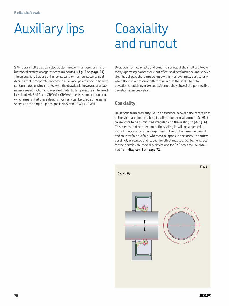
SKF radial shaft seals can also be designed with an auxiliary lip for
increased protection against contaminants († ig. 2 on page 63)
These auxiliary lips are either contacting or non-contacting Seal
designs that incorporate contacting auxiliary lips are used in heavily
contam inated environments, with the drawback, however, of creat-
ing increased friction and elevated underlip temperatures The auxil-
iary lip of HMSA10 and CRWA1 / CRWHA1 seals is non-contacting,
which means that these designs normally can be used at the same
speeds as the single-lip designs HMS5 and CRW1 / CRWH1
Deviation from coaxiality and dynamic runout of the shaft are two of
many operating parameters that affect seal performance and service
life They should therefore be kept within narrow limits, particularly
when there is a pressure differential across the seal The total
deviation should never exceed 1,3 times the value of the permissible
deviation from coaxiality
Coaxiality
Deviations from coaxiality, i e the difference between the centre lines
of the shaft and housing bore (shaft-to-bore misalignment, STBM),
cause force to be distributed irregularly on the sealing lip († ig. 6)
This means that one section of the sealing lip will be subjected to
more force, causing an enlargement of the contact area between lip
and counterface surface, whereas the opposite section will be corres-
pond ingly unloaded and its sealing effect reduced Guideline values
for the permissible coaxiality deviations for SKF seals can be obtai-
ned from diagram 3 on page 71
Auxiliary lips Coaxiality and runout
Fig. 6
Coaxiality
7070
Radial shaft seals
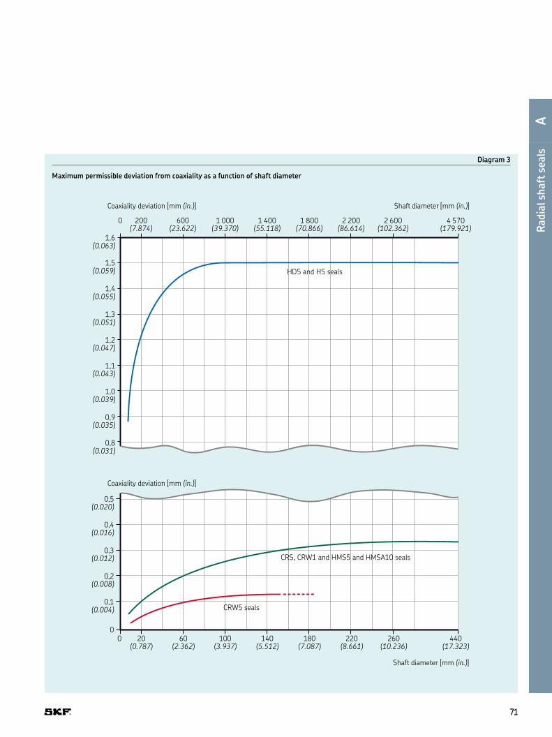
Diagram 3
Maximum permissible deviation from coaxiality as a function of shaft diameter
0,5(0.020)
0,4(0.016)
0,3(0.012)
0,2(0.008)
0,1(0.004)
0100(3.937)
0 20(0.787)
60(2.362)
140(5.512)
180(7.087)
220(8.661)
260(10.236)
440(17.323)
1,5(0.059)
1,6(0.063)
1,4(0.055)
1,3(0.051)
1,2(0.047)
1,1(0.043)
1,0(0.039)
0,9(0.035)
0,8(0.031)
Coaxiality deviation [mm (in.)]
HDS and HS seals
CRS, CRW1 and HMS5 and HMSA10 seals
CRW5 seals
Shaft diameter [mm (in.)]
4 570 (179.921)
2 600 (102.362)
2 200 (86.614)
1 800 (70.866)
1 400 (55.118)
1 000 (39.370)
600 (23.622)
200 (7.874)
0
Shaft diameter [mm (in.)]
Coaxiality deviation [mm (in.)]
7171
C
D
E
F
G
H
I
Radia
l shaft
sea
lsA

Runout
Runout (or dynamic runout, DRO) describes the dynamic eccentricity
of the shaft Particularly at high speeds, there is a risk that the seal-
ing lip, because of its inertia, will not be able to follow the shaft sur-
face († ig. 7) If the eccentricity is such that the distance between
the sealing lip and shaft becomes larger than that required to main-
tain a hydrodynamic lubricant ilm, the medium to be sealed will
escape through the gap It is therefore advisable to arrange the seal
in close proximity to the bearing and to keep bearing operating
clearance to a minimum
Permissible runout values can be obtained from diagram 4 on
page 73 These values are normally lower for narrow seals and
always depends on seal cross section, sealing lip material and
operating temperature
Fig. 7
Runout
7272
Radial shaft seals

Diagram 4
Maximum permissible runout as a function of rotational speed
1,1(0.043)
1,0(0.039)
0,9(0.035)
0,8(0.031)
0,7(0.028)
0,4(0.016)
0,3(0.012)
0,2(0.008)
0,1(0.004)
01 0000 2 000 3 000 4 000 5 000 6 000 7 000
1 0000
Runout [mm (in.)]
Runout [mm (in.)]
HDS and HS seals
CRS, CRW1 and HMS5 and HMSA10 seals
CRW5 seals
Rotational speed [r/min]
Rotational speed [r/min]
2 000 3 000 4 000 5 000 6 000 7 000
7373
C
D
E
F
G
H
I
Radia
l shaft
sea
lsA

Small movements of the shaft relative to the housing in the axial
direction do not affect seal performance, provided that the total
counterface surface meets the same demands regarding to hard-
ness, accuracy and surface inish
Guideline values for the permissible rotational and circumferential
speeds for different seal designs are provided in the seal selection
charts (matrix 2 on pages 176 to 183) If the circumferential speeds
provided in the matrix are not suficient for a particular sealing
position, diagram 5 from DIN 3760 on page 75 may be used The
diagram lists circumferential and rotational speeds related to the
material of the sealing lip The values are valid for spring-loaded
sealing lips that are well-lubricated by a mineral oil, where adequate
lubricant supply prevents heat build-up and where the pressure is
the same on both sides of the seal (pressure differential = 0)
Diagram 5 on page 75 shows that large diameter shafts can
accommodate higher circumferential speeds than shafts with
smaller diameters This is because the cross section of the shaft does
not increase linearly with the increase in diameter but by the square
of the increase in diameter Therefore, the heat dissipation of a large
shaft is much better than that of a small shaft
Generally, SKF Wave seals can be operated at higher circumferential
speeds than those obtained from diagram 5 on page 75 because of
the hydrodynamic form of the lip
The values obtained from diagram 5 on page 75 should be
reduced if
• radial shaft seals with an auxiliary, contacting lip are used,
• lubrication is inadequate or grease lubrication is used, i e when
underlip temperatures increase due to poor heat dissipation,
• the counterface does not meet surface inish or running accuracy
requirements or
• there is a pressure differential across the seal
Axial movement
Permissible speeds
7474
Radial shaft seals

Diagram 5
Permissible speeds for spring-loaded sealing lips where no pressure differential exists across seal in operation For permissible speeds for seals at shaft diameters > 200 mm, refer to seal selection chart starting on page 104.
0 20(0.787)
40(1.575)
60(2.362)
80(3.150)
100(3.937)
120(4.724)
140(5.512)
Shaft diameter [mm (in.)]
Circumferential speed [m/s (ft/min)] Rotational speed [1 000 r/min]
Fluoro rubber
Polyacrylate elastomer
Nitrile rubber
160(6.299)
180(7.087)
200(7.874)
0,5
1,0
1,5
2,0
2,5
3,0
3,5
0
5(984)
10(1 969)
15(2 953)
20(3 937)
25(4 921)
30(5 906)
35(6 890)
40(7 874)
5,06,07,08,09,010,015,0 4,5 4,0
Source: DIN standard 3760
7575
C
D
E
F
G
H
I
Radia
l shaft
sea
lsA

To seal eficiently over a long period, the sealing lip of a radial shaft
seal must be lubricated This reduces friction and wear to the sealing
lip and shaft Dry running of sealing lips made of standard materials
should always be avoided To prevent dry running, coat the counter-
face surface with a suitable lubricant prior to seal installation
The lubricant not only lubricates the sealing lip to reduce friction
and wear, but also dissipates heat generated by the seal To promote
heat dissipation, a suficient quantity of lubricant needs to reach the
sealing lip from start-up
Some rolling bearings, such as angular contact ball bearings,
tapered roller bearings and spherical roller thrust bearings, as well
as gears, create a pumping action by virtue of their design This
means that the sealing lip can either be starved of lubricant, or sub-
jected to excessive quantities of lubricant In either case, steps must
be taken during the design stage to make sure that the proper
amount of lubricant reaches the sealing lip, as too much or too little
can affect seal performance
To prevent lubricant starvation, lubrication ducts can be provided
If the seal is subjected to excessive amounts of lubricant, a linger can
be installed between the bearing and the seal.
In applications where the sealing lip is not exposed to a lubricant,
for example when two seals are installed in tandem, grease or oil
must be separately supplied to provide suficient lip lubrication In
some cases, it may be suficient to provide an initial grease ill
between the two lips
Lubrication of paired arrangements
When two radial shaft seals are installed back-to-back or in tandem,
the space between the seals should be illed with a suitable lubricant
to eliminate the risk of the sealing lip running dry
To further prevent dry running, a spacing washer between the
seals can also be used This spacing washer should be provided with
lubri cation holes or an annular groove and lubri cation holes so that
grease can be supplied to the space between the seals via a grease
itting († ig. 8)
To be effective, the lip of a radial shaft seal must always exert a cer-
tain radial load on the coun ter face The friction resulting from this
radial load is only part of the total contact friction and power loss
at the sealing position Other con trib uting factors include:
• Type of medium being sealed
• Pressure differential across the seal
• Circumferential speed
• Ambient temperature
• Lubricant and lubrication method
• Condition of the counterface
• Sealing material
• Lip surface roughness
• Shaft roughness
Diagram 6 on page 77 provides an indication of the friction losses
that may be expected when a radial shaft seal with a conventional
sealing lip is properly installed and fully lubricated.
The running-in phase of the sealing lip lasts a few hours. During
this time, the friction losses are somewhat higher than during
normal operation.
Seals intended for applications with high pressure differentials
typically have greater losses than speciied in the diagram SKF Wave
seals, on the other hand, typically have losses lower than those
indicated in the diagram
Lubrication Friction
Fig. 8
Lubrication of a paired arrangement
7676
Radial shaft seals

Diagram 6
Friction losses of radial shaft seals as a function of rotational speed and shaft diameter
100
200
300
400
500
600
0
5 000Friction loss [W]
Rotational speed [r/min]
4 000 3 000
10(0.394)
20(0.787)
40(1.575)
60(2.362)
80(3.150)
100(3.937)
120(4.724)
140(5.512)
500
2 000
1 000
Shaft diameter [mm (in.)]
7777
C
D
E
F
G
H
I
Radia
l shaft
sea
lsA

The most important factor when selecting the appropriate elastomer
for a radial shaft seal is its chemical resistance to the medium to be
sealed or excluded. The operating temperature is another important
factor. Heat accelerates ageing of the elastomer and increases the
re activ ity and aggressiveness of the sealed medium.
Radial shaft seals are mainly used to seal lubricating oils and
greases as well as hydraulic luids (including non-lammable luids).
Guideline values are provided in table 4 for the permissible operat-
ing temperatures, i.e. temperatures at which the SKF seals are still
chemically resistant. The temperature range stated for a group of
media means that the sealing material is resistant when continu-
ously op er ated within this particular range.
The N means that, within the group, there are some media that
are compatible with the elastomer, but also some that have a
detrimen tal effect on the elastomer.
The n means that the seal material is not resistant to media
belonging to this group.
For the resistance of sealing materials to media not listed in
table 4, refer to the section Chemical resistance († page 36) or
contact SKF.
Chemical and thermal resistance
Table 4
Chemical and thermal resistance, radial shaft sealing lip materials
Medium to be sealed Permissible operating temperatures (continuous) for SKF radial shaft sealing lip materials1)
R P S V(NBR) (ACM) (MVQ) (FKM)
– °C °F °C °F °C °F °C °F
Mineral oil based lubricants
Motor oils 100 210 130 270 150 300 170 340
Gear oils 80 175 120 250 130 250 150 300
Hypoid gear oils 80 175 120 250 n 150 300
Automatic transmission luids (ATF oils) 100 210 130 270 N 170 340
Greases 90 195 N N N
Hydraulic luids 90 195 120 250 N 150 300
Fire-resistant hydraulic luids
Oil in water emulsions and aqueous polymer solutions
70 160 n 60 140 N
Anhydrous luids n n n 150 300
Other media
Fuel oils EL and L 90 195 N n N
Water 90 195 n n 100 210
Alkaline washing solutions 90 195 n n 100 210
Permissible temperature rangefor sealing lip min : –40 –40 –40 –40 –60 –75 –40 –40
max : +100 +210 +150 +300 +160 +320 +200 +390
n Lip material not resistant
N Lip material not resistant to some media in this group
1) R = nitrile rubber P = polyacrylate elastomer S = silicone rubber V = luoro rubber
7878
Radial shaft seals

F
F
p
p
p
F
100%
400%
700%
Radial contact force [F]
O kPa(0 psi)
200 kPa(29 psi)
400 kPa
System pressure [p]
(58 psi)
When a seal is exposed to pressure, the radial load of the sealing lip
increases. This in turn increases the actual sealing lip / shaft contact
area, resulting in additional friction and elevated underlip tempera-
tures. Therefore, the guideline values for speeds provided in
diagram 5 on page 75 do not apply.
Diagram 7 shows an example of lip distortion of a conventional
sealing lip design. System pressure pushes the sealing lip onto the
counterface and this leads to sealing lip distortion and increased
radial force. This results in higher friction, more frictional heat and
consequentially reduced seal service life.
SKF CRW5 and CRWA5 pressure proile seals († ig. 9) are
designed to withstand pressure differentials of 0,34 MPa (50 psi) at
speeds up to 5 m/s (1 000 ft/min)
When there is a pressure differential across the seal, a shoulder or
retaining ring should be used at the low-pressure side of the seal to
prevent it from being pressed out of the housing bore († ig. 10)
Seals under pressure
Fig. 9
Pressure proile seals
Fig. 10
CRWA5 seal
CRW5 CRWA5
Diagram 7
System pressure pushes the sealing lip onto the counterface and leads to sealing lip distorion and increased radial force. This results in higher friction, more frictional heat and – consequentially – reduced seal service life.
7979
C
D
E
F
G
H
I
Radia
l shaft
sea
lsA

General
To achieve reliable sealing performance and maximum service life,
the counterface for a radial shaft seal should meet the requirements
outlined below. The seal counterface must be able to accommodate
all permissible deviations and movements – surface SL and an addi-
tional surface SL’ – which may be required in the case of repairs or
inspection († ig. 11).
In cases where a shaft cannot be machined to meet the require-
ments, SKF recommends the use of SKF Speedi-Sleeve or a wear
sleeve for heavy industrial applications (LDSLV). Detailed information
about sleeves is provided in the chapter Wear sleeves starting on
page 232.
Tolerances
The diameter of the shaft d1 at the counterface should be machined
to the tolerances provided in table 6 on page 81 for metric shafts
and table 7 on page 81 for inch-size shafts
Out-of-roundness must be less than 0,005 mm (0.0002 in)
at a maximum of 2 lobes or less than 0,0025 mm (0.0001 in)
at a max imum of 7 lobes
If components with an interference it will pass over the counter-
face during installation, the shaft diameter should be reduced by
0,2 mm (0.008 in)
Surface roughness
The surface roughness values of the counterface for radial shaft
seals, calculated according to methods described in ISO 4288
(DIN 4768), should be kept within the limits spe ciied in RMA OS-1-1
(† table 5)
The lower value for Ra is a minimum value Using a lower value will
adversely affect the lubri cant supply to the sealing lip The tempera-
ture rise caused by inadequate lubri cation, particularly at high
circumferential speeds, can lead to hardening and cracking of the
sealing lip which will eventually lead to premature seal failure If the
counterface is too rough, there will be exces sive sealing lip wear and
seal service life will be shortened If the value Rpm is exceeded, the
seal will leak or excessive sealing lip wear may occur
Shaft requirements
Table 5
Recommended shaft surface roughness values
ISO DIN RMA
µm µin µm µin µm µin
Ra 0,2–0,5 8–20 0,2–0,8 8–32 0,2–0,43 8–17
Rz 1,2–3 48–120 1–5 40–200 1,65–2,9 65–115
Rpm N/A N/A N/A N/A 0,5–1,5 20–50
Fig. 11
Counterface for radial shaft seals
SL
SL’
8080
Radial shaft seals

Surface inish
Depending on the direction of rotation, directionality on the seal
counterface may cause a seal to leak. Plunge grinding is the pre-
ferred machining method to minimize directionality (0±0,05°) on the
seal counterface When plunge grinding, whole number ratios of the
grinding wheel speed to the work piece speed should be avoided
Run the grinding wheel until it “sparks out” completely, i e until there
are no more sparks lying from the wheel, to ensure that all lead is
removed The grinding wheel should be dressed using a cluster head
dressing tool and the smallest possible lateral feed, or a proile dress-
ing roll without lateral feed The negative inluence of directionality in
any particular case can only be ascertained by test running under
conditions of alternating rotation
The seal counterface surface should be free of any damage,
scratches, cracks, rust or burrs and should be properly protected
until inal installation
Hardness and surface treatment
The surface hardness of the seal counterface should be at least 30
HRC (58 HRC for PTFE lip seals) If the counterface surface could be
damaged during transport or installation, this value should be
increased to 45 HRC (62 HRC for PTFE lip seals) Under certain con-
ditions, where speeds are low, lubrication is good and contaminants
are absent, counterface surfaces having a lower hardness may be
suitable Surfaces that are nitrided, phosphated or have a galvanized
coating may also be suitable, but this must be determined for each
speciic case
Table 6
Counterface tolerances for metric shafts
Shaft diameter Diameter tolerance (ISO h11)1)
Nominal Deviationd1over incl high low
mm µm
6 10 0 –9010 18 0 –11018 30 0 –130
30 50 0 –16050 80 0 –19080 120 0 –220
120 180 0 –250180 250 0 –290250 315 0 –320
315 400 0 –360400 500 0 –400500 630 0 –440
630 800 0 –500800 1 000 0 –5601 000 1 250 0 –660
1 250 1 600 0 –7801 600 2 000 0 –9202 000 2 500 0 –1 100
2 500 3 150 0 –1 3503 150 4 000 0 –1 6504 000 5 000 0 –2 000
Table 7
Counterface tolerances for inch-size shafts
Shaft diameter Diameter tolerance (RMA 0S-4)Nominal Deviationd1over incl high low
in in
– 4 +0 003 –0 003
4 6 +0 004 –0 004
6 10 +0 005 –0 005
10 +0 006 –0 006
1) For shaft diameters of 3 150 mm and above, refer to DIN 7172
8181
C
D
E
F
G
H
I
Radia
l shaft
sea
lsA

Table 8
Lead-in chamfers and radii
Shaft diameter Diameter Radii
Nominal difference1) Seal without auxiliary lip
Seal with auxiliary lip
d1 d1 – d2 r rover incl over incl min min min
mm in mm in mm in mm in
– 10 – 0.394 1,5 0.059 0,6 0.024 1 0.039
10 20 0.394 0.787 2 0.079 0,6 0.024 1 0.039
20 30 0.787 1.181 2,5 0.098 0,6 0.024 1 0.039
30 40 1.181 1.575 3 0.118 0,6 0.024 1 0.039
40 50 1.575 1.968 3,5 0.138 0,6 0.024 1 0.039
50 70 1.968 2.756 4 0.157 0,6 0.024 1 0.039
70 95 2.756 3.740 4,5 0.177 0,6 0.024 1 0.039
95 130 3.740 5.118 5,5 0.216 1 0.039 2 0.079
130 240 5.118 9.449 7 0.276 1 0.039 2 0.079
240 500 9.449 19.685 11 0.433 2 0.079 3 0.118
500 – 19.685 – 13 0.512 5 0.197 5 0.197
1) lf the corner is blended rather than chamfered, the blended section should not be smaller than the difference in diameters d1 – d2
d2d1 h11
r
15–30°
ZY
Burr-free
Lead-in chamfers
To install radial shaft seals without damaging the sealing lip, SKF
recommends chamfering or rounding the shaft ends or shoulders
(† table 8)
If the direction of installation is Z, the values (d1 – d2) provided in
table 8 should be adhered to If the direction of installation is Y, the
shaft end could be either rounded (r) or chamfered (d1 – d2)
To install a seal over a shaft shoulder or end that has not been
rounded or chamfered, SKF recommends using an installation
sleeve See section Seal installation, heavy industrial applications
on page 89
8282
Radial shaft seals

1) ISO – The housing bore surface roughness may require lower values when metal-cased seals are used, in which case they should be subject to agreement between the manufacturer and user
2) RMA – If the bore surface texture is greater than 2,5 µm (100 µin) Ra, a sealant should be used 3) RMA – Turned bores, where a lubricant head of up to 0,20 bar (3.0 psi) is present at the seal If this texture is maintained
and tool removal marks or bore defects are not present, no outside diameter leakage should occur
General
To reduce the risk of seal damage during installation, the housing
bore should have a 15 to 30° lead-in chamfer The chamfer should
be free of burrs and the transition radius r between the seal seat
and shoulder should be in accordance with the recommendations
in table 10 on page 84
In order to facilitate seal removal, holes in the housing shoulder
A can be incorporated during the design stage
Metal-reinforced seals
The depth of a metric housing bore B for metal-cased or metal-
inserted seals should be at least 0,3 mm (0.012 in) larger than
the nominal seal width b († ig. 12) The corresponding values for
an inch housing bore B are 0,4 mm (0.016 in)
Seals without metal-reinforcement
Seals without metal reinforcement are manufactured oversized
relative to the housing bore diam eter and depth to enable proper
com pres sion and stability The actual seal width is approximately
0,4 to 0,8 mm (0.016 to 0.032 in) wider than the bore depth B For
all-rubber HS seals, the bore depth tolerance should be ±0,13 mm
(0.005 in) and ±0,10 mm (0.004 in) for all-rubber reinforced HSS
seals and fabric-reinforced HSF seals For seals without metal rein-
forcement, a cover plate is required for a proper it († page 94)
Tolerances
The housing bore diameter D should be machined to tolerance H8
(† table 10 on page 84) Depending on the operating conditions,
out-of-roundness should be 1 to 2 tolerance grades better than H8
Surface roughness
The surface roughness (to ISO 4288 or DIN 4768) of the housing
bore should be kept within the limits speciied in table 9
Housing bore requirements
Fig. 12
Housing bore requirements
B
D H8
15–30°
A
b
Table 9
Recommended housing bore surface roughness values
ISO1) DIN RMA2)3)
µm µin µm µin µm µin
Ra 1,6–3,2 64–128 1,6–3,2 64–128 1–2,5 40–100
Rz 6,3–12,5 252–500 10–20 400–800 N/A N/A
Rmax N/A N/A N/A N/A 0,5–1,5 20–50
8383
C
D
E
F
G
H
I
Radia
l shaft
sea
lsA

Table 10
Housing bore tolerances
Housing bore for metric seals (ISO)
Housing bore for inch-size seals (RMA)
Nominal diameter
Housing bore tolerance(ISO tolerance H8)
Fillet radii
Nominal diameter
Housing bore tolerance Fillet radii
D r D rover incl high low max over incl high low max
mm µm mm in in in
– 3 +14 0 0,3 – 3.000 +0 001 –0 001 0 0313 6 +18 0 0,3 3.000 7.000 +0 0015 –0 0015 0 0316 10 +22 0 0,3 7.000 10.000 +0 002 –0 002 0 031
10 18 +27 0 0,3 10.0002) 12.000 +0 002 –0 002 0 03118 30 +33 0 0,3 12.0002) 20.000 +0 003 –0 003 0 03130 50 +39 0 0,3 20.0002) 40.000 +0 004 –0 004 0 031
50 80 +46 0 0,4 40.0002) 60.000 +0 006 –0 006 0 03180 120 +54 0 0,8120 180 +63 0 0,8
180 250 +72 0 0,8250 315 +81 0 0,8315 400 +89 0 0,8
400 500 +97 0 0,8500 630 +110 0 0,8630 800 +125 0 0,8
800 1 000 +140 0 0,81 000 1 250 +165 0 0,81 250 1 600 +195 0 0,8
1 600 2 000 +230 0 0,82 000 2 500 +280 0 0,82 500 3 150 +330 0 0,8
3 1501) 4 000 +410 0 0,84 0001) 5 000 +500 0 0,8
1) SKF recommended bore speciications not covered in ISO 286-22) SKF recommended bore speciications not covered in RMA OS-4
B
D H8
15–30°
rA
8484
Radial shaft seals

Table 11
Shaft and bore requirements for HRS seals
Housing bore for metric seals (ISO) Range Tol Tol minimum HRS1 HRS1 HRSA HRS1 HRSA +HRE HRS1 HREincl. up to (recom-
mended)HRSA +HRE HRS1 HRE HRSA
d1 D CS B S1 S2 LRS C
mm
350 900 –0,4 +0,4 ≥ 20 (25) ≥ 20 ≥ 25 ≤ 12 ≤ 12 7-12 ≥ 15 ≥ 25 ≥ B + 10 ≤ 10 ≤ 1,5
900 1 800 –0,5 +0,5 ≥ 25 (32) ≥ 25 ≥ 30 ≤ 16 ≤ 16 7-16 ≥ 15 ≥ 30 ≥ B + 10 ≤ 10 ≤ 1,5
1 800 3 900 –0,7 +0,7 ≥ 28 (32) ≥ 25 ≥ 30 ≤ 18 ≤ 18 7-18 ≥ 15 ≥ 30 ≥ B + 10 ≤ 10 ≤ 1,5
Surface roughnessThe surface roughness values of the counter-face for these radial shaft seals, calculated according to methods described in ISO 4288 (DIN 4768), should be:
Ra ≤0 8µm Material ratio: 50 95% at 50% of Rz, Cref=0%
If higher values are used, the seal life may be affected If the counterface is too rough, there can be excessive sealing lip wear and seal service life might be be shortened
Surface inish Depending on the direction of rotation, directionality on the seal counterface may cause a seal to leak Plunge grinding is the preferred machining method to minimize directionality (0±0,05°) on the seal counterface The seal counterface surface should be solid, free of any damage, scratches, cracks, rust or burrs and should be properly protected until inal installation
Hardness and surface treatment The surface hardness of the seal counterface should be at least 45 HRC Under certain conditions, such as where speeds are low, lubrication is good and contaminants are absent, counterface surfaces having a lower hardness may be suitable Surfaces that are nitrided, phosphated or have a galvanized coating may also be suitable, but this must be determined for each speciic case
B ±0,1C
D d1
S2S1
CS
LRS
8585
C
D
E
F
G
H
I
Radia
l shaft
sea
lsA

Table 12
Housing bore requirements for HS/SS seals
Lead-in chamfers and radii
Shaft diameter Nominal
Diameter difference 1)
Radii Lead-in chamfersTo reduce the risk of seal damage during installation, the housing bore should have a 15° to 30° lead-in chamfer The chamfer should be free of burrs and the transition radius r between the seal seat and shoulder should be in accordance with the recommen-dations in table 12.
TolerancesFor all-rubber HSS seals, the bore depth tolerance should be 0,10 mm (0.004 in)
d1 d1 – d2 r2over incl over incl min min
mm in mm in mm in
165 240 6.500 9.499 7 0.276 1 0.039240 500 9.449 19.685 11 0.433 2 0.079500 19.685 13 0.512 5 0.197
Table 13
Recommended housing bore surface roughness values
ISO 1) DIN RMA 2) 3) Surface roughnessThe surface roughness (to ISO 4288, DIN 4768 or RMA OS-1-1) of the housing bore should be kept within the limits speciied in table 13. µm µin µm µin µm µin µm
Ra 1,6–3,2 64–128 1,6–3,2 64–128 1–2,5 40–100 0 039Rz 6,3–12,5 252–500 10–20 400–800 N/A N/A 0 079Rpm N/A N/A 25 1 000 N/A N/A 0 197
1) If the corner is blended rather than chamfered, the blended section should not be smaller than the difference in diameter d1 – d2
1) ISO – The housing bore surface roughness may require lower values when metal-cased seals are used, in which case they should be subject to agreement between the manufacturer and user
2) RMA – If the bore surface texture is greater than 2,5 µm (100 µin) Ra, a sealant should be used 3) RMA – Turned bores, where a lubricant head of up to 0,20 bar (3.0 psi) is present at the seal If this texture is maintained
and tool removal marks or bore defects are present, no outside diameter leakage should occur
d2d1 h11D H8
r2
15–30°
r = 0,8 (0.031)
15–30°
B ±0,10 (±0.004)
ZY
8686
Radial shaft seals

General
To provide effective sealing, radial shaft seals must be installed
properly. An experienced installer with suitable tools, working in a
clean environment, is recommended to provide proper installation.
The shaft counterface surface and housing bore should meet the
demands speciied under Shaft Housing bore requirements on
pages 83 to 86
To facilitate seal installation and to achieve ini tial lubrication, prior
to installation, SKF recom mends wiping the shaft and seal with
the lubricant that is going to be retained While the outside diameter
of metal-cased seals can be lightly lubricated to ease installation,
the outside diam eter of rubber covered seals should
always be lubricated
Seals with an auxiliary, contacting lip can also be illed with grease
between the sealing lip and auxiliary lip to reduce frictional moment
This does not apply to silicone rubber seals and seals with hydrody-
namic features, other than SKF Wave lip designs
SKF also recommends using a hydraulic press, with suitable tools,
to install a seal in its housing bore Pressure should be applied as
close as possible to the outside diameter of the seal
Seals that are designed to sit lush with the wall of the housing
bore must be installed perpendicular to the housing bore axis. The
outside diameter of the tool should be larger than the housing bore
diameter († ig. 13).
When pressing seals up against a shoulder or retaining ring, it
is advisable to use tools of the type shown in igs. 14 and 15. The
necessary ring dimensions can be supplied on request.
Seal installation, general industrial applications
di ≈ D – 6 mm
D di
d7
d7 = d3 – 0,5 mm
d3
d7 = D – 0,5 mm
d7
D
Fig. 13
Preferred installation method
Fig. 14
Alternative installation method
Fig. 15
Alternative installation method
8787
C
D
E
F
G
H
I
Radia
l shaft
sea
lsA

When installing seals on stepped shafts, where the shoulders do
not have the recommended chamfer or rounded transition, an instal-
lation sleeve as shown in ig. 17 must be used. If the sealing lip has
to pass over grooves, threads or gearing, thin-walled installation
sleeves, like those shown in ig. 18, can be used to prevent the lip
from being damaged. The outside surface of the sleeve should be
coated with the same lubricant that is used to lubricate the seal and
counterface surface.
Radial shaft seals with a sealing lip made of a sensitive material
should always be installed using an installation sleeve.
The tools used to install a seal at a certain distance in a cylindrical
opening in a housing
are shown in igs. 19 and 20. Instructions for designing the tools
can be supplied on request.
d7
d3
d7 = d3 – 0,5 mm
Fig. 16
Installation sleeve
Fig. 17
Thin-walled installation sleeve
Fig. 18
Installation in a cylindrical opening
Fig. 19
Installation in a cylindrical opening
8888
Radial shaft seals

Seal installation, heavy industrial applications
General
• Recommended seal installation temperature +5 to 40 °C
Polymeric materials shrink or expand depending on the environ-
ment temperature. Installing a seal at very low temperatures
might lead to a gap between the ends of the seal. Installing a seal
at very high temperatures might lead to a more dificult installation
process If seals have to or are installed in a very cold environment,
warming the seals or the surroundings with a heating gun (max
80 °C) until the cover plates are applied, is recommended
• Work clean
Before work begins, the cleanliness of the working environment
must be checked Dust and dirt that enters the application, or con-
taminates the seal or garter spring, during the seal replacement
might lead to premature failure replacement
• Handle with care
Seals are fragile components that have to be handled with care
Dust and abrasive particles, a damaged or bent sealing lip or a
carelessly installed spring can cause a service life reduction, leak-
age or consequential damage Avoid contact with sharp objects Do
not slide the sealing edge over housing parts
• Do not install seal without visibility
It is crucial that the sealing lip is visible during the installation and
that any installation failure (e g sealing lip bending) is avoided by
supporting the sealing lip to slide onto the shaft as intended Make
sure that the garter spring stays in the spring groove and that the
sealing lip is not damaged or bent backwards during the installa-
tion process
Preparation
Split seals are specially packed for up-tower service The seals are
delivered cut with the ends secured to avoid damage during trans-
port Prior to installation, the transportation protection must be
removed
Cut the tape with scissors to open the packaging Avoid touching
the seal with sharp tools
Instructions
Make sure that the necessary equipment is ready:
• Seal and garter spring in their respective package
• Knife or scissors to open the seal packaging
• Flashlight (to check the seal lip right after installation)
• Wood screw to dismount the used seal out of the housing bore
• A cleaning cloth to clean the housing bore during seal replacement
• Tools required to dismount and install the cover plates
• Optional but recommended: adhesive for securing the spring
connection (Permabond HM162, Marston-Domsel MD666 620
or Loctite 243)
8989
C
D
E
F
G
H
I
Radia
l shaft
sea
lsA

Metal-cased – HDS seals
When installing metal-reinforced seals, the irst step is to check the
shaft and housing bore for proper speciications and condition Next,
coat both the seal and bore lightly with a lubricant, preferably the
same one that will be used to lubricate the application For large
diameter seals, a special installation tool may not be practical In
these cases, do not hit the seal or seal case dir ectly Instead, use a
wooden block, long enough to span the seal’s outside diameter
When using this method, it is important to apply hammer-blows
evenly and sequentially to the wood piece around the seal circum
ference to prevent the seal from tilting or skewing SKF also recom-
mends the use of a dead blow hammer for full energy transfer with
less impact († ig. 20)
In some applications, the housing is designed for two seals in tan-
dem, or a seal might have to be recessed further into the bore depth
In those cases, irst set the seal flush with the housing using the
method described above. Then, use a shorter piece of wood to
drive the seal deeper into the bore utilizing a sequential pattern
(† ig. 21).
Seals are installed differently depending on whether their main
purpose in a speciic application is to retain lubricant or to exclude
contaminants († ig. 22)
1 2
3
4 5
6 7
8
12
3
4
5
67
8
Fig. 20
Use a dead blow hammer
Fig. 21
Installation deeper into the bore
Fig. 22
Ways of installing (e.g. all-rubber HS seals)
All-rubber seal installed to retain lubricant
All-rubber seal installed to exclude foreign material
All-rubber seals in tandem arrangement for maximum lubricant retention
9090
Radial shaft seals

Split seals – HRS
Ensure shaft and housing bore requirements
listed in the SKF drawing are met. Clean
shaft surface and housing bore and make
sure that they meet the speciications
1 Position the garter spring around the shaft
at the installation position († A in ig. 23)
2 Connect the spring (A)
a) Apply adhesive on open spring
connection
b) Back-wind the spring 7 full turns
c) Screw the spring together leaving no
gap
3 Dismount the used seal from the housing
bore
4 Lightly coat the counterface with a lubri-
cant, preferably the same that will be used
in the application (B)
5 Position the seal joint on the shaft so that
it is at the 12 o’clock position (C)
6 Insert the garter spring into the groove
trying to apply equal tension around the
circumference
7 Compress and push both ends of the joint
into the housing bore (D)
8 Continue at the 6, 3 and 9 o’clock posi-
tions, push the rest of the seal into posi-
tion and inish simultaneously Use a small
block of wood if needed to push the seal in
the housing bore until it contacts the
housing shoulder (E)
9 If an excluder seal HRE1 is used, position it
around the shaft and push it against the
back of the installed primary seal with the
sealing lip facing to the opposite direction
Position the joint at the 6 o’clock position
The excluder seal may try to go out of the
housing Hold it in place until the cover
plates are installed (F)
10 Check the seal condition, particu-
larly at the joint, to make sure that it has
been positioned properly Install the cover
plate on the housing face Tighten the
bolts evenly until the cover plate abuts the
housing face (G)
Fig. 23
Installing a HRS split seal
A E
B F
C
D
G
a
b
c
7x
9191
C
D
E
F
G
H
I
Radia
l shaft
sea
lsA

Split seals – HS and HSS
1 Where appropriate, insert the spring in
the SKF Springlock groove and position
the spring connection, so that it is dis-
placed with regard to the seal joint († A in
ig. 24) This is standard with all HS8
seals Put the seal in the correct position
on the shaft
2 Lightly coat both the seal and counterface
surface with a lubricant, preferably the
same lubricant that will be used to lubri-
cate the appli cation (B)
3 Join the ends of the garter spring by using
the spring connector (C)
4 For threaded connectors, back-wind the
spring a couple of turns before the ends
are brought together and allowed to
thread into each other When using a
hook-and-eye connector, draw the ends of
the spring together and insert the hook
into the eye, taking care not to over-
stretch the spring in the process, as this
might impair seal performance When
using a control-wire connector, draw the
seal ends together and insert the control
wire into the centre of the spring coil
5 Position the seal joint on the shaft so that
it is at the 12 o’clock position and push
both ends of the joint into the housing
bore (D) Do not push only one joint and
then work around the shaft as this will
create an excess length, making installa-
tion dificult or impossible
6 Continue at the 3 and 9 o’clock positions,
push the rest of the seal into position (E)
and inish simultaneously at the 6 and 12
o’clock positions For shaft diameters ≥
1 200 mm (47 in), it is advis able to ix the
seal at the 12, 3, 6 and 9 o’clock positions
before locating the remaining sections of
the seal
7 Use a small block of wood to push the seal
in the housing bore until it contacts the
housing shoulder (E)
Fig. 24
Installing an all-rubber split seal
A E
B
F
C
G
D
9292
Radial shaft seals

8 Check the seal condition, particularly at
the joint, to make sure that it has been
positioned properly
9 Install the cover plate (see paragraph
Cover plates on page 94) on the housing
face Tighten the bolts evenly until the end
cover abuts the housing face
(F and G)
Installation of HRS and HSS split seals
Video of HRS split seals installation in a wind turbine
9393
C
D
E
F
G
H
I
Radia
l shaft
sea
lsA

Cover plates
Seals without metal reinforcement, split and solid, are manufactured
oversized relative to the housing bore diameter and depth to enable
proper compression and stability A cover plate († ig. 25) provides
axial compression of the seal and stabilizes it in the housing bore
to achieve maximum seal perform ance The cover plate must be
dimensioned properly to obtain the required it It should be thick
enough not to bend or distort Generally, a thickness of 6,35 to
12,7 mm (0.25 to 0.50 in) is suficient
The plate should be fastened with bolts, no more than 150 mm
(6 in) apart, on a bolt circle located as close to the seal housing bore
as practical The cover plate should be lat and the housing bore
depth uniform Splitting the cover plate at 180° will make seal
replacement easier, particularly in conined areas
To block surges of lubricant toward the seal from the inside and
to protect the seal from damage from the outside, SKF recommends
dimensioning the inside diameter of the cover plate so that it is 6 to
8 mm (0.25 to 0.30 in) greater than the shaft diameter to accommo-
date shaft-to-bore misalignment and runout († ig. 25)
In applications where supplementary sealing is necessary, and it
is impractical to machine the original housing to provide a seal cavity,
a seal cavity can be incorporated into a new plate that is bolted into
place as illustrated in ig. 26 on page 95
N
P D D1 d1
Fig. 25
Cover plate recommendations
Inside diameter of cover:Pitch circle diameter of screws:No of attachment screws:
D1 ≈ d1 + 6 8 [mm]P ≈ 1,1 D [mm]N ≈ 0,02 P
9494
Radial shaft seals

Multiple HS seal installations
When installing two split all-rubber HS seals in one cavity, the loca-
tions of the split joints should be staggered by 30° to 60° to minimize
the risk of leakage through the joints The splits should be located
toward the top of the bore Grease the cavity between the seals to
provide lubricant to the outer sealing lip
When two HS seals, split or solid, are installed in the same hous-
ing bore, a spacing washer must be placed between the two seals
(† ig. 27) Suitable washer dimensions can be determined based
on the shaft and housing bore diameters, d1 and D, respectively:
• Washer inside diameter
= d1 + 6 to 10 mm (0.25 to 0.4 in)
• Washer outside diameter
= D – 0,5 to 1,5 mm (0.02 to 0.06 in)
The width of the washer is determined by the application conditions
There should, however, always be suficient room for lubrication
holes to be provided in the circumference, or lubrication grooves in
one side face († ig. 28) These lubrication provisions must enable
grease to be supplied from the housing to the sealing lips via a drilled
passage or grease itting († ig. 29 on page 96) When determining
what washer width is appropriate for the depth of a housing bore, it
is ne cessary to consider the axial displacement required when
clamping the seals
Fig. 26
Cover plate
Fig. 27
Spacing washer
Fig. 28
Details of spacing washer for central lubricationA separator between two seals can be a slotted washer to promote distribution of the lubricant
6,35 – 12,7 mm
New seal cavity plate
Seal-retaining cover plate
Sealing element
d1 + 6,4 mm (d1 + 0.25 in)
D – 0,5 / 1,5 mm(D – 0.06 in)
9595
C
D
E
F
G
H
I
Radia
l shaft
sea
lsA

Multiple HDS seal installations
When installing two metal-cased radial shaft seals in the same
housing bore, either in a tandem or back-to-back arrangement, care
must be taken that neither of the sealing lips can run dry at any time
To reduce the risk of dry running, the space between the seals should
be illed with a suitable grease
To avoid dry running, SKF recommends using spacer lugs or a
spacing washer between the two seals The spacing washer should
be provided with lubrication holes so that grease can be supplied to
the space between the sealing lips via a grease itting († ig. 29)
No spacing washer is required when using seals that have spacer
lugs built into the air side of the metal case († ig. 30) HDSD and
HDSE seals can be supplied from SKF with holes pre-drilled in
the metal case to mate with corresponding pas sages in the
housing bore
PTFE seals
In most cases, small diameter PTFE seals are shipped on a tube that
maintains a nominal seal inside diameter (smaller than shaft diame-
ter) during storage Therefore, they should not be removed from the
shipping tube until immediately prior to installation Also, if quality
inspections must be done, SKF recommends that the shipping tube
remains in place The seal inside diameter cannot be accurately
measured anyway after manufacturing as the PTFE lip coniguration
changes over time as it relaxes
PTFE formulations used for radial lip seals are generally more
aggressive and abrasive to the shaft than standard elastomeric
materials Therefore, PTFE sealing lips require a surface hardness
value of 58 to 62 HRC An alternative to a hardened shaft surface is
the use of an SKF wear sleeve, manufactured to the same high
standards such as the inner rings of SKF needle roller bearings,
offering an excellent sealing surface
In applications where PTFE seals will be retaining a lubricant or be
fully looded with a luid, the seals should be installed dry In applica-
tions that run dry or will be starved for lubrication, the sealing lip
should be pre-lubricated with a grease appropriate for the tempera-
ture conditions of the application
Fig. 29
Spacing washer and grease itting
Fig. 30
Spacer lug
� WARNING
At temperatures above 300 °C (570 °F), all PTFE compounds
give off dangerous fumes For additional information, refer to
page 33
9696
Radial shaft seals

Installation procedure
PTFE lips do not have the same elastic prop erties as rubber lips,
which makes them more susceptible to damage Therefore, special
care must be taken during installation and handling to prevent dam-
age and help ensure proper operation and function Shaft features
such as keyways and splines, as well as drill holes, ports and sharp-
edged shaft steps have the potential to damage PTFE lips Whenever
possible, these obstructions can be covered by using thin-walled
installation tools made from plastic or metal
PTFE lip orientation during installation will determine the installa-
tion method Installation is more dificult when the shaft is installed
against the PTFE lip († ig. 31, a and c) This type of installation
becomes even more complicated when the hardware is dificult to
access or visually obstructed and may not be possible if an installa-
tion tool cannot be used In any case, when the shaft is installed
against the PTFE lip, SKF recommends the use of an installation
cone or “bullet” SKF can quote and manufacture installation cones if
detailed drawings of the shaft and sealing areas are provided In lieu
of installation cones, longer than normal lead-in chamfers on the
shaft would be required However, shaft features that could damage
the seal (keyways, etc ) must still be covered, possibly with tape
If the shaft is installed with the PTFE lip, a smooth, burr-free
radius or chamfer on the shaft end is all that is required, provided
that no damaging shaft features are present as noted above
(† ig. 31, b and d).
Some seals have two PTFE lips facing oppos ite directions In this
case, installation is always against one of the lips and an installation
cone is recommended
Fig. 31
Seals with a PTFE sealing lip
Seals with an elastomeric sealing lip and a PTFE auxilary lip
d) Installation with the PTFE lip
instal- lation cone
c) Installation against the PTFE lip
shipping tube
b) Installation with the PTFE lip
shipping tube instal- lation cone
a) Installation against the PTFE lip
elastomeric sealing lip
PTFE auxiliary lip
lead-in chamfer
lead-in chamfer
9797
C
D
E
F
G
H
I
Radia
l shaft
sea
lsA

The seal counterface surface should be protected from corrosion
until the machine is oper ational Be sure to use a rust inhibitor that
will last for a year, whether or not the shaft is exposed
The protective coating should be soluble in the medium to be
retained and must not cause any chemical separation as this can
impair the sealing performance
When machines are transported, stored under unfavourable con-
ditions, or out of service for extended periods, special rust inhibitors
should be used These rust inhibitors should form a tough, pliable
waxy ilm that can be removed using neutral solvents that leave
an oily residue
Protecting the counterface surface against corrosion
9898
Radial shaft seals

Removal Replacement
Fig. 33
Spacing ring
Because radial shaft seals should never be reused, there is no need
to worry about damaging the seal when removing it However, prior
to removal, it is advisable to note the direction in which the seal is
installed so that the replacement seal can be installed in the same
direction Small seals can generally be removed using a screwdriver,
taking care not to damage the shaft surface The removal of large-
size seals is made easier if holes have been provided in the housing
shoulder A, see picture in table 10, page 84, allowing access for
a drift
The lip of the replacement seal should not run on the same path as
the lip of the old seal There are several ways to achieve this:
• Install SKF Speedi-Sleeve, see page 240
• Rework or replace the counterface
(this may entail removing the shaft)
• Install a spacing ring in the housing bore between
the housing shoulder and the seal († ig. 32)
• Press the new seal to a different depth in a cylindrical opening
in the housing, i e toward the medium to be sealed
When choosing a replacement seal, be sure that its design and
material correspond to the original seal In case of doubt, select a
seal that meets the operating conditions of the application, and that
the seal materials are compatible with the lubricant
Seals made from a different material should only be used when
absolutely necessary In these cases, the recommendations provided
in table 14 should be followed The order in which the materials are
listed is an indication of their suitability
If a seal of the same design is not available in the same width as
the original, then a somewhat narrower seal can be used, or if the
depth of the housing bore allows, a somewhat wider seal can be
selected as the replacement
Table 14
Replacement sealing lip materials
Original Replacement
Felt Nitrile rubber
Polyacrylate elastomer
Fluoro rubber
Leather Nitrile rubber
Fluoro rubber
Nitrile rubber Polyacrylate elastomer
Fluoro rubber
Silicone rubber
Polyacrylate elastomer Fluoro rubber
Silicone rubber
Silicone rubber Fluoro rubber
9999
C
D
E
F
G
H
I
Radia
l shaft
sea
lsA

Seals for general industrial applicationsA.1
100100
Radial shaft seals | Seals for general industrial applications

50%OF PREMATURE
BEARING FAILURE
IS RELATED TO
SEALING ISSUES
Seals for general industrial applications
› Improved performance
› Easy installation
101101
C
D
E
F
G
H
I
Sea
ls for
gen
eral i
ndust
rial a
pplica
tions
A.1

Metric radial shaft seals
Designations of all SKF metric radial shaft seals specify shaft diameter,
housing bore diameter and nominal seal width (bore depth for HSF
and HS seals) in millimetres, followed by design and the code
of the sealing lip material († table 1)
Inch-size radial shaft seals
Inch-size SKF radial shaft seals are identiied by their stock number
that consists of four to seven digits. The stock number provides an
indication of seal size.
• Four-igure numbers are used for radial shaft seals for
shaft diameters: d1 ≤ 1 in, e.g.
3680 d1= 0.375 in
• Five-igure numbers are used for radial shaft seals for
shaft diameters: d1 ≤ 10 in, e.g.
41287 d1 = 4.125 in
97545 d1 = 9.750 in
• Six- and seven-igure numbers are used for
radial shaft seals for
shaft diameters: d1 ≥ 10 in, e.g.
120061 d1 = 12 in
1375242 d1 = 13.75 in
Designation system
Table 1
Designation system for metric radial shaft seals
55 72 8 HMSA10 RG 1
Dimensions
55 Shaft diameter
72 Housing bore diameter
8 Nominal seal width (bore depth for HSF and HS seals)
Design
HMSA10
Lip material
RG Acrylonitrile-butadiene rubber, SKF developed, used for the HMS5 and HMSA10 seals
Execution
1, 2… Seals of the same size and design that differ in execution from the basic design are identiied by a number e.g. R1
102102
Radial shaft seals

Assortment, availability and classiication
The SKF assortment of radial shaft seals comprises some 200
designs and executions for applications within basically all industries.
The radial shaft seals described in this publication belong to the
standard range and most of them are available in both metric and
inch sizes. New seal designs and sizes are continually added.
For additional information, contact SKF.
Designation system | Assortment, availability and classiication
General industrial applications
> 4 1/2 inch, misalignment,availibility or prototyping
HIS (Heavy Industrial Seals)
MSC (Machined Seals Concept)
Grease lubricatedHM and TL seals
Sealing against housing bore
X seals
CRW5 CRWA51 )
Internal pressure up to 50 psi
CRWH1 CRWHA11 )
HMS5 HMSA101 ) CRW1 CRWA11 )
Bore retention and sealing lip protection
Metric standard Inch standard
1) Same seal design with auxiliary lip for further protection
103103
C
D
E
F
G
H
I
Sea
ls for
gen
eral i
ndust
rial a
pplica
tions
A.1

Designation system for metric radial shaft seals
RG, R Nitrile rubber
V Fluoro rubberT Polytetraluoroethylene (PTFE)
Seal designs Design
Outside diameter Sealing lip Auxiliary lip
Coniguration Material code Coniguration Material code A = Contacting
B = Non-contacting
–
Rubber RG, V Straight RG B (HMSA10)
V
HMS5 HMSA10
Metal N/A SKF Wave R N/A
V
CRW1 CRWH1
Metal N/A SKF Wave R B
V
CRWA1 CRWHA1
Metal N/A SKF Wave R A (CRWA5)
V
CRW5 CRWA5
Metal N/A Straight R N/A
V
CRS1 CRSH1
Metal N/A Straight R A
V
CRSA1 CRSHA1
Metal N/A Straight R N/A
V
HM14
Rubber R Special R N/A
X15
Metal N/A Special T N/A
SL SLX SLS
Metal N/A Special T A (SLA, DLA)
SLA DL DLA
Fluoroplastic / (rubber)
T (+ R, V) Special T N/A
YSLE YNSLE YSL
* PTFE designs are made to order to handle temperatures, pressures and speeds that may exceed those stated for rubber sealing lip designs.
104104
Radial shaft seals

Matrix 1
Operating temperature range Shaft-to-bore mis- alignment (STBM) TIR
Dynamic runout (DRO) TIR
Pressure differential
Maximum shaft surface speed
from to from to
°C °F mm in mm in MPa psi m/s ft/min
–40 100 –40 210 0,38 0.015 0,51 0.020 0,05 7 14 2 755
–40 200 –40 390
–40 100 –40 210 0,38 0.015 0,51 0.020 0,07 10 18 3 600
–40 200 –40 390
–40 100 –40 210 0,38 0.015 0,51 0.020 0,07 10 18 3 600
–40 200 –40 390
–40 100 –40 210 0,13 0.005 0,13 0.005 0,35 50 10 2 000
–40 200 –40 390
–40 100 –40 210 0,38 0.015 0,51 0.020 0,07 10 18 3 600
–40 200 –40 390
–40 100 –40 210 0,38 0.015 0,51 0.020 0,07 10 18 3 600
–40 200 –40 390
–40 100 –40 210 0,13 0.005 0,08 0.003 0,07 10 10 2 000
–40 200 –40 390
–40 100 –40 210 0,38 0.015 0,25 0.010 0,02 3 2,54 500
–70 250 –95 480 * * * * * * * *
–70 250 –95 480 * * * * * * * *
–70 250 –95 480 * * * * * * * *
Assortment and availability
105105
C
D
E
F
G
H
I
Sea
ls for
gen
eral i
ndust
rial a
pplica
tions
A.1

Main features
SKF metric rubber outside diameter radial
shaft seals, HMS5 and HMSA10, are
designed in accordance with ISO 6194-1 and
DIN 3760 for use in a wide range of indus-
trial applications. The available size range
of HMS5 and HMSA10 seals includes a full
coverage of the ISO 6194-1 and DIN 3760
dimensions for shaft diameters up to 250
mm (9.842 in) as well as an extensive range
of dimensions commonly used in the market.
New dimensions are continually added. Main
features include:
• Optimized sealing lip material
• Spring-loaded sealing lip
• Optimally balanced sealing lip and lex
section
• Beaded outside diameter
• Auxiliary lip (HMSA10 seals only
Design
The rubber outside diameter provides opti-
mized sealing ability in the housing, also at
considerable surface roughness or in split
housings. The beads on the outside diameter
provide improved sealing ability and retention
in the bore. They also prevent spring-back
during installation.
The spring-loaded sealing lip contributes
to a quick response in handling dynamic
runout and maintaining the sealing perfor-
mance, even when sealing lip wear is
excessive.
Sealing lip and lex section are optimally
balanced to withstand both high dynamic
runout and shaft-to-bore misalignment.
The auxiliary lip on HMSA10 seals is
non-contacting, which means that the seals
normally can operate at the same speeds
as the single-lip HMS5 seals.
Material
The optimized nitrile rubber compound used
for the HMS5 and HSMA10 seals has the
desig nation sufix RG. The compound is the
result of long experience and the latest ind-
ings from the SKF sealing material develop-
ments. Advantages of this material include:
• Good resistance to ageing
• Very good compatibility with synthetic oils
• Very good pumping ability
• Good wear resistance
Pumping ability is deined as the time it takes
for the seal to return a certain amount of oil
from the air side to the oil side. The micro-
structure of SKF’s RG nitrile rubber com-
pound promotes rapid pumping of the oil, (†
table 2 on page 107). In diagram 1 on page
107, results from endurance tests show the
extended service life of seals made of the
optimized nitrile compound.
The complete range of HMS5 and
HMSA10 seals is also available in a luoro
rubber compound with a stainless steel
garter spring. This rubber compound has
the designation sufix V and is used in appli-
cations where temperatures exceed the
limits of nitrile rubber.
HMS5 and HMSA10 seals
HMS5
HMSA10
Fig. 1
Fig. 2
106106
Radial shaft seals | Seals for general industrial applications

Applications and operating conditions
HMS5 and HMSA10 seals are designed for
oil or grease lubricated applications with
operating temperatures ranging from –40
to +100 °C (–40 to +210 °F), short-term up
to 120 °C (250 °F). These seals are also
appropriate for sealing lubricants within
a wide range of viscosities.
• Circumferential speed: up to 14 m/s
(2 755 ft/min)
• Operating pressure: max. 0,05 MPa
(7 psi)
These values are the maximum value for
each service condition and should not occur
together. Consideration should be given as
to how the operating conditions affect each
other. For information on seals under
pressure, see page 79.
New sizes
If the necessary size is not listed in the prod-
uct tables on the following pages, we can
add more sizes on request (also in inch size).
Contact your local SKF representative.
Table 2
Pumping ability
Speed Pumping timeRotating Circum ferential Standard NBR SKF compound
RG
r/min m/s s
1 000 3,1 – 117
1 500 4,7 280 69
2 000 6,3 186 50
2 500 7,9 130 40
3 000 9,4 102 31
3 500 11,0 82 25
4 000 12,6 68 21
4 500 14,1 57 18
Shaft diameter 60 mm, engine oil SAE 30
Diagram 1
Average seal life(as a percentage of baseline, product A)
0
100
200
300
400
500
Product AStandard NBR compound
Product BHigh-perform-ance NBR compound
Product CStandard SKF compound RG
HMS5 and HMSA10
107107
C
D
E
F
G
H
I
Sea
ls for
gen
eral i
ndust
rial a
pplica
tions
A.1

Product tables
b
d1 D
1) Designation to be followed by the design and material codes, indicating one of the four variants available for each dimension:
HMS5 RG without auxiliary lip, nitrile rubber HMS5 V without auxiliary lip, luoro rubber HMSA10 RG with auxiliary lip, nitrile rubber HMSA10 V with auxiliary lip, luoro rubber Example: 6×16×5 HMSA10 RG
2) Design execution differs from the basic design and is indicated by a number, see also page 102.
Please see pages 85 and 86 for housing bore requirements.
Radial shaft seals | Seals for general industrial applications | HMS5 and HMSA10
d1 6–25 m
Dimensions Designation1) ISO / DINShaft Bore Nominal
seal widthd1 D b
mm – –
6 16 5 6×16×516 7 6×16×7 •
22 7 6×22×7 •
7 16 7 7×16×72)
22 7 7×22×7 •
8 18 5 8×18×518 7 8×18×7
22 7 8×22×7 •
24 7 8×24×7 •
9 22 7 9×22×7 •
10 19 7 10×19×72)
20 6 10×20×620 7 10×20×7
22 7 10×22×7 •
24 7 10×24×7
25 7 10×25×7 •
26 7 10×26×7 •
30 7 10×30×7
12 19 5 12×19×52)
22 5 12×22×522 6 12×22×622 7 12×22×7 •
24 7 12×24×7 •
25 7 12×25×7 •28 7 12×28×7
Dimensions Designation1) ISO / DINShaft Bore Nominal
seal widthd1 D b
mm – –
12 30 7 12×30×7 •cont.
32 7 12×32×7
37 7 12×37×7
13 26 7 13×26×7
14 24 7 14×24×7 •
25 5 14×25×5
28 7 14×28×7
30 7 14×30×7 •
15 24 7 15×24×72)
25 5 15×25×525 6 15×25×6
26 7 15×26×7 •
30 7 15×30×7 •
32 7 15×32×7
35 7 15×35×7 •
40 7 15×40×740 10 15×40×10
16 24 7 16×24×72)
28 7 16×28×7
30 7 16×30×7 •
32 7 16×32×7
35 7 16×35×7 •
17 28 7 17×28×7
108

HMS5 and HMSA10
Dimensions Designation1) ISO / DINShaft Bore Nominal
seal widthd1 D b
mm – –
17 29 5 17×29×5cont.
30 7 17×30×7
32 7 17×32×7
35 7 17×35×7
37 7 17×37×7
40 7 17×40×7
40 10 17×40×10.
47 7 17×47×747 10 17×47×10
18 28 7 18×28×7
30 6 18×30×630 7 18×30×7 •
32 7 18×32×7
35 7 18×35×7 •
40 7 18×40×7
19 30 7 19×30×730 8 19×30×8
32 7 19×32×7
42 6 19×42×6
20 30 5 20×30×530 7 20×30×7 •
32 6 20×32×632 7 20×32×7
34 7 20×34×7
35 6 20×35×635 7 20×35×7 •35 8 20×35×835 10 20×35×10
36 7 20×36×7
38 7 20×38×7
40 7 20×40×7 •40 10 20×40×10
42 7 20×42×742 10 20×42×10
45 7 20×45×7
47 7 20×47×747 10 20×47×10
52 7 20×52×752 10 20×52×10
21 35 7 21×35×7
40 7 21×40×7
Dimensions Designation1) ISO / DINShaft Bore Nominal
seal widthd1 D b
mm – –
22 32 7 22×32×7
35 7 22×35×7 •
36 7 22×36×7
38 8 22×38×8
40 7 22×40×7 •40 10 22×40×10
42 10 22×42×10
45 7 22×45×747 7 22×47×7 •
23 40 10 23×40×10
24 35 7 24×35×7
37 7 24×37×7
40 7 24×40×7
42 8 24×42×8
47 7 24×47×7
50 10 24×50×10
25 35 6 25×35×635 7 25×35×7 •
37 5 25×37×537 6 25×37×637 7 25×37×7
38 7 25×38×7
40 5 25×40×540 7 25×40×7 •40 8 25×40×840 10 25×40×10
42 6 25×42×642 7 25×42×742 10 25×42×10
45 7 25×45×745 8 25×45×845 10 25×45×10
46 7 25×46×7
47 7 25×47×7 •47 10 25×47×10
50 10 25×50×10
52 7 25×52×7 •52 8 25×52×852 10 25×52×10
62 7 25×62×762 8 25×62×862 10 25×62×10
72 7 25×72×7
109
A.1
Sea
ls for
gen
eral i
ndust
rial a
pplica
tions

b
d1 D
1) Designation to be followed by the design and material codes, indicating one of the four variants available for each dimension:
HMS5 RG without auxiliary lip, nitrile rubber HMS5 V without auxiliary lip, luoro rubber HMSA10 RG with auxiliary lip, nitrile rubber HMSA10 V with auxiliary lip, luoro rubber Example: 6×16×5 HMSA10 RG
2) Design execution differs from the basic design and is indicated by a number, see also page 102.
Please see pages 85 and 86 for housing bore requirements.
Radial shaft seals | Seals for general industrial applications | HMS5 and HMSA10
d1 26–40 mm
Dimensions Designation1) ISO / DINShaft Bore Nominal
seal widthd1 D b
mm – –
26 37 7 26×37×7
38 5 26×38×538 7 26×38×7
42 7 26×42×7
47 7 26×47×7
27 37 7 27×37×7
42 10 27×42×10
43 7 27×43×7
47 7 27×47×747 10 27×47×10
28 38 7 28×38×738 8 28×38×8
40 7 28×40×7 •40 8 28×40×8
42 7 28×42×742 8 28×42×8
44 6 28×44×6
45 8 28×45×8
47 7 28×47×7 •47 10 28×47×10
52 7 28×52×7 •52 10 28×52×10
30 40 7 30×40×7 •
42 6 30×42×642 7 30×42×7 •42 8 30×42×8
30 44 7 30×44×7
Dimensions Designation1) ISO / DINShaft Bore Nominal
seal widthd1 D b
mm – –
30 45 7 30×45×7cont. 45 8 30×45×8
46 7 30×46×7
47 6 30×47×647 7 30×47×7 •47 8 30×47×847 10 30×47×10
48 8 30×48×8
50 5 30×50×550 7 30×50×750 8 30×50×850 10 30×50×10
52 7 30×52×7 •52 8 30×52×852 10 30×52×10
55 7 30×55×755 10 30×55×10
62 7 30×62×762 10 30×62×10
72 10 30×72×10
32 42 7 32×42×7
43 7 32×43×7
44 7 32×44×745 7 32×45×7 •45 8 32×45×8 •
47 6 32×47×647 7 32×47×7 •47 8 32×47×8 •47 10 32×47×10
48 8 32×48×8
110

HMS5 and HMSA10
Dimensions Designation1) ISO / DINShaft Bore Nominal
seal widthd1 D b
mm – –
32 50 8 32×50×8cont. 50 10 32×50×10
52 7 32×52×7 •52 8 32×52×8 •
55 10 32×55×10
62 10 32×62×10
72 7 32×72×7
80 7 32×80×7
33 45 7 33×45×7
50 6 33×50×6
34 44 8 34×44×8
48 8 34×48×8
52 8 34×52×8
62 10 34×62×10
35 45 7 35×45×7
47 6 35×47×647 7 35×47×7 •47 8 35×47×8 •
48 8 35×48×8
49 6 35×49×6
50 7 35×50×7 •50 8 35×50×8 •50 10 35×50×10
52 7 35×52×7 •52 8 35×52×8 •52 10 35×52×10
55 7 35×55×7 •55 8 35×55×8 •55 10 35×55×10
56 10 35×56×10
58 10 35×58×10
60 10 35×60×10
62 7 35×62×762 8 35×62×862 10 35×62×10
72 7 35×72×772 10 35×72×1072 12 35×72×12
80 12 35×80×12
36 47 7 36×47×7
50 7 36×50×7
52 7 36×52×7
Dimensions Designation1) ISO / DINShaft Bore Nominal
seal widthd1 D b
mm – –
36 58 10 36×58×10cont.
62 7 36×62×7
37 50 6 37×50×6
38 50 7 38×50×7
52 7 38×52×752 8 38×52×8
54 10 38×54×10
55 7 38×55×7 •55 8 38×55×8 •55 10 38×55×10
58 8 38×58×8 •58 10 38×58×10
60 10 38×60×10
62 7 38×62×7 •62 8 38×62×8 •62 10 38×62×10
72 10 38×72×10
80 8 38×80×8
38,5 58 7 38.5×58×7
40 50 8 40×50×8
52 6 40×52×652 7 40×52×7 •52 8 40×52×8 •
55 7 40×55×7 •55 8 40×55×8 •
56 8 40×56×8
58 7 40×58×758 8 40×58×858 10 40×58×10
60 8 40×60×860 10 40×60×10
62 6 40×62×662 7 40×62×7 •62 8 40×62×8 •62 10 40×62×10
65 10 40×65×1065 12 40×65×12
68 8 40×68×868 10 40×68×10
70 8 40×70×8
72 7 40×72×772 10 40×72×10
80 8 40×80×880 10 40×80×1080 12 40×80×12
111
A.1
Sea
ls for
gen
eral i
ndust
rial a
pplica
tions

b
d1 D
1) Designation to be followed by the design and material codes, indicating one of the four variants available for each dimension:
HMS5 RG without auxiliary lip, nitrile rubber HMS5 V without auxiliary lip, luoro rubber HMSA10 RG with auxiliary lip, nitrile rubber HMSA10 V with auxiliary lip, luoro rubber Example: 6×16×5 HMSA10 RG
2) Design execution differs from the basic design and is indicated by a number, see also page 102.
Please see pages 85 and 86 for housing bore requirements.
Radial shaft seals | Seals for general industrial applications | HMS5 and HMSA10
d1 40–70 mm
Dimensions Designation1) ISO / DINShaft Bore Nominal
seal widthd1 D b
mm – –
40 90 10 40×90×10cont. 90 12 40×90×12
41 56 7 41×56×7
42 53 7 42×53×7
55 7 42×55×755 8 42×55×8 •
56 7 42×56×7
60 7 42×60×7
62 7 42×62×762 8 42×62×8 •
62 10 42×62×10
65 10 42×65×1065 12 42×65×12
66 10 42×66×10
67 10 42×67×10
72 8 42×72×872 10 42×72×10
43 62 8 43×62×8
44 60 10 44×60×10
62 10 44×62×10
65 10 44×65×10
45 55 7 45×55×7
58 7 45×58×7
60 7 45×60×760 8 45×60×8 •60 10 45×60×10
Dimensions Designation1) ISO / DINShaft Bore Nominal
seal widthd1 D b
mm – –
45 62 7 45×62×7cont. 62 8 45×62×8 •
62 10 45×62×10
65 8 45×65×8 •65 10 45×65×10
68 7 45×68×768 10 45×68×1068 12 45×68×12
72 8 45×72×872 10 45×72×10
75 8 45×75×875 10 45×75×10
80 10 45×80×10
85 10 45×85×10
100 10 45×100×10
46 59 12 46×59×12
65 10 46×65×10
47 65 10 47×65×10
70 10 47×70×10
90 10 47×90×10
48 62 8 48×62×8 •
65 10 48×65×10
68 10 48×68×10
70 10 48×70×10
72 7 48×72×772 8 48×72×872 10 48×72×10
112

HMS5 and HMSA10
Dimensions Designation1) ISO / DINShaft Bore Nominal
seal widthd1 D b
mm – –
50 62 7 50×62×7
64 6 50×64×6
65 8 50×65×8 •65 10 50×65×10
68 7 50×68×768 8 50×68×8 •68 10 50×68×10
70 10 50×70×10
72 8 50×72×8 •72 10 50×72×1072 12 50×72×12
75 10 50×75×10
80 8 50×80×880 10 50×80×10
85 10 50×85×10
90 10 50×90×10
100 10 50×100×10
52 63 8 52×63×8
65 8 52×65×8
68 8 52×68×8
72 8 52×72×872 10 52×72×10
80 10 52×80×10
85 10 52×85×10
100 10 52×100×10
55 68 8 55×68×8
70 8 55×70×8 •70 10 55×70×10
72 8 55×72×8 •72 10 55×72×10
75 8 55×75×875 10 55×75×10
78 10 55×78×1078 12 55×78×12
80 8 55×80×8 •80 10 55×80×10
85 8 55×85×885 10 55×85×10
90 8 55×90×890 10 55×90×10
100 10 55×100×10100 12 55×100×12
56 72 8 56×72×8
Dimensions Designation1) ISO / DINShaft Bore Nominal
seal widthd1 D b
mm – –
57 67 7 57×67×7
58 72 8 58×72×8
80 8 58×80×880 10 58×80×1080 12 58×80×12
60 72 8 60×72×8
75 8 60×75×8 •
80 7 60×80×780 8 60×80×8 •80 10 60×80×10
82 12 60×82×12
85 8 60×85×8 •85 10 60×85×10
90 8 60×90×890 10 60×90×10
95 10 60×95×10
100 10 60×100×10
110 8 60×110×8110 8 60×110×10
62 80 10 62×80×10
85 10 62×85×10
90 10 62×90×10
63 85 10 63×85×10
90 10 63×90×10
64 80 8 64×80×8
65 80 8 65×80×8
85 8 65×85×885 10 65×85×10 •85 12 65×85×12
88 12 65×88×12
90 10 65×90×10 •
95 10 65×95×10
97 7 65×97×7
100 10 65×100×10
110 10 65×110×10
120 12 65×120×12
140 12 65×140×12
68 90 10 68×90×10
70 85 8 70×85×8
113
A.1
Sea
ls for
gen
eral i
ndust
rial a
pplica
tions

b
d1 D
1) Designation to be followed by the design and material codes, indicating one of the four variants available for each dimension:
HMS5 RG without auxiliary lip, nitrile rubber HMS5 V without auxiliary lip, luoro rubber HMSA10 RG with auxiliary lip, nitrile rubber HMSA10 V with auxiliary lip, luoro rubber Example: 6×16×5 HMSA10 RG
2) Design execution differs from the basic design and is indicated by a number, see also page 102.
Please see pages 85 and 86 for housing bore requirements.
Radial shaft seals | Seals for general industrial applications | HMS5 and HMSA10
d1 70–250 mm
Dimensions Designation1) ISO / DINShaft Bore Nominal
seal widthd1 D b
mm – –
70 90 7 70×90×72)cont. 90 10 70×90×10 •
90 12 70×90×12
92 12 70×92×12
95 10 70×95×10 •
100 10 70×100×10
110 10 70×110×10110 12 70×110×12
72 90 10 72×90×10
95 10 72×95×1095 12 72×95×12
100 10 72×100×10
140 12 72×140×12
75 90 10 75×90×10
95 10 75×95×10 •95 12 75×95×12
100 10 75×100×10 •100 12 75×100×12
105 10 75×105×10
110 12 75×110×12
120 12 75×120×12
130 12 75×130×12
78 100 10 78×100×10
80 95 10 80×95×10
100 10 80×100×10 •100 12 80×100×12
Dimensions Designation1) ISO / DINShaft Bore Nominal
seal widthd1 D b
mm – –
80 105 10 80×105×10cont.
110 10 80×110×10 •110 12 80×110×12
115 12 80×115×12
125 12 80×125×12
170 13 80×170×13
82 120 12 82×120×12
160 15 82×160×15
85 100 9 85×100×9100 10 85×100×10
105 12 85×105×12
110 12 85×110×12 •
115 12 85×115×12
120 12 85×120×12 •
130 12 85×130×12
140 12 85×140×12
150 12 85×150×12
90 110 10 90×110×10110 12 90×110×12 •
115 12 90×115×12
120 12 90×120×12 •
95 110 12 95×110×12
115 12 95×115×12
120 12 95×120×12 •
114

HMS5 and HMSA10
Dimensions Designation1) ISO / DINShaft Bore Nominal
seal widthd1 D b
mm – –
95 125 12 95×125×12 •cont.
140 12 95×140×12
145 12 95×145×12
170 13 95×170×13
100 120 10 100×120×10120 12 100×120×12 •
125 12 100×125×12 •
130 12 100×130×12 •
140 12 100×140×12
145 12 100×145×12
150 12 100×150×12
105 130 12 105×130×12 •
135 12 105×135×12
140 12 105×140×12
108 140 15 108×140×15 •
170 15 108×170×15
110 130 12 110×130×12 •130 13 110×130×13
140 12 110×140×12 •
150 12 110×150×12
115 140 12 115×140×12 •
145 12 115×145×12
150 12 115×150×12
118 150 12 118×150×12
120 140 12 120×140×12140 13 120×140×13
150 12 120×150×12
160 12 120×160×12
180 15 120×180×15
125 150 12 125×150×12 •
160 15 125×160×15
200 15 125×200×15
130 160 12 130×160×12 •160 15 130×160×15
170 12 130×170×12
180 12 130×180×12
190 12 130×190×12
Dimensions Designation1) ISO / DINShaft Bore Nominal
seal widthd1 D b
mm – –
135 170 12 135×170×12 •
140 160 12 140×160×12
170 12 140×170×12 •170 15 140×170×15
180 12 140×180×12
145 175 15 145×175×15 •
180 12 145×180×12
148 170 15 148×170×15
150 170 12 150×170×12
180 12 150×180×12180 15 150×180×15 •
200 12 150×200×12
155 180 15 155×180×15
160 185 15 160×185×15
190 15 160×190×15 •
165 190 15 165×190×15
170 200 15 170×200×15 •
175 200 15 175×200×15
180 200 15 180×200×15
210 15 180×210×15 •
190 220 15 190×220×15 •
225 15 190×225×15
200 230 15 200×230×15 •
210 240 15 210×240×15 •
220 250 15 220×250×15 •
230 260 15 230×260×15 •
240 270 15 240×270×15 •
250 280 15 250×280×15 •
285 15 250×285×15
115
A.1
Sea
ls for
gen
eral i
ndust
rial a
pplica
tions

Main features
These radial shaft seals are low-friction
seals with SKF Wave lip design for reduced
heat genera tion See pages 68 and 69 for
more infor mation on SKF Wave lip design
They have a metal outside diameter for easy
installation and a irm and accurate it in the
housing bore.
The seals feature SKF Bore Tite Coating
on the outside diameter, a non-hardening,
water-based acrylic sealant that helps ill
small imperfections in the housing bore.
They are primarily designed to retain
lubricants but are also suitable for contami-
nant exclusion, especially the CRWA1 and
CRWHA1 seals designed with an auxiliary lip.
Design
• CRW1: Seal with a single steel case, SKF
Wave lip and a carbon steel garter spring.
• CRWH1: Seal with a double steel case,
SKF Wave lip and a carbon steel garter
spring.
• CRWA1: Seal with a single steel case, SKF
Wave lip, a carbon steel garter spring and
an auxiliary, non-contacting lip.
• CRWHA1: Seal with a double steel case,
SKF Wave lip, a carbon steel garter spring
and an auxiliary, non-contacting lip.
All of these seals are available with sealing
lips made of either nitrile rubber or the SKF
developed luoro rubber compound SKF
Duralife. Other materials are also available
on request.
See matrix 1 on pages 104 and 105 for
permissible operating conditions.
CRW1, CRWA1, CRWH1 and CRWHA1 seals
CRW1 CRWH1
CRWA1 CRWHA1
Fig. 3 Fig. 4
Fig. 5 Fig. 6
116116
Radial shaft seals | Seals for general industrial applications

Product tables
b
d1 D
Please see pages 83 to 86 for housing bore requirements
Dimensions Design and DesignationShaft Bore Nominal
seal widthlip material
d1 D b
mm – –
12 22 7 CRW1 V 12×22×7 CRW1 V22 7 CRW1 R 12×22×7 CRW1 R25 7 CRW1 R 12×25×7 CRW1 R26 7 CRW1 R 12×26×7 CRW1 R28 7 CRW1 R 12×28×7 CRW1 R28 7 CRW1 P 12×28×7 CRW1 P
32 7 CRW1 R 12×32×7 CRW1 R32 7 CRW1 V 12×32×7 CRW1 V35 7 CRW1 R 12×35×7 CRW1 R
14 26 7 CRW1 V 14×26×7 CRW1 V32 7 CRW1 R 14×32×7 CRW1 R
15 25 7 CRW1 P 15×25×7 CRW1 P28 7 CRW1 R 15×28×7 CRW1 R32 7 CRW1 R 15×32×7 CRW1 R32 7 CRW1 V 15×32×7 CRW1 V
35 7 CRW1 R 15×35×7 CRW1 R35 7 CRW1 P 15×35×7 CRW1 P
16 28 7 CRW1 R 16×28×7 CRW1 R30 7 CRW1 R 16×30×7 CRW1 R32 7 CRW1 R 16×32×7 CRW1 R35 7 CRW1 R 16×35×7 CRW1 R
40 7 CRW1 R 16×40×7 CRW1 R40 7 CRWA1 R 16×40×7 CRWA1 R
17 27 6,35 CRW1 R 17×27×6 CRW1 R28 7 CRW1 R 17×28×7 CRW1 R28 7 CRW1 V 17×28×7 CRW1 V
30 7 CRW1 R 17×30×7 CRW1 R32 7 CRW1 R 17×32×7 CRW1 R35 7 CRW1 R 17×35×7 CRW1 R35 7 CRW1 V 17×35×7 CRW1 V
40 7 CRW1 R 17×40×7 CRW1 R47 7 CRW1 R 17×47×7 CRW1 R
CRW1, CRWA1, CRWH1 and CRWHA1 – metric dimensions
d1 12–22 mm
Dimensions Design and DesignationShaft Bore Nominal
seal widthlip material
d1 D b
mm – –
18 30 7 CRW1 R 18×30×7 CRW1 R30 7 CRW1 V 18×30×7 CRW1 V32 7 CRW1 R 18×32×7 CRW1 R32 7 CRW1 V 18×32×7 CRW1 V
35 7 CRW1 R 18×35×7 CRW1 R40 7 CRW1 R 18×40×7 CRW1 R
19 35 7 CRW1 R 19×35×7 CRW1 R
20 30 7 CRW1 R 20×30×7 CRW1 R31 7 CRW1 R 20×31×7 CRW1 R32 7 CRW1 R 20×32×7 CRW1 R
35 7 CRW1 R 20×35×7 CRW1 R35 7 CRW1 V 20×35×7 CRW1 V36 7 CRW1 R 20×36×7 CRW1 R36 7 CRW1 V 20×36×7 CRW1 V
37 7 CRW1 R 20×37×7 CRW1 R38 7 CRW1 R 20×38×7 CRW1 R
40 7 CRW1 R 20×40×7 CRW1 R40 7 CRW1 V 20×40×7 CRW1 V42 7 CRW1 R 20×42×7 CRW1 R47 7 CRW1 R 20×47×7 CRW1 R
52 7 CRW1 R 20×52×7 CRW1 R52 7 CRW1 P 20×52×7 CRW1 P
21 35 7 CRW1 R 21×35×7 CRW1 R35 7 CRW1 V 21×35×7 CRW1 V40 8 CRW1 R 21×40×8 CRW1 R
22 31 7 CRW1 P 22×31×7 CRW1 P32 7 CRW1 R 22×32×7 CRW1 R
35 7 CRW1 R 22×35×7 CRW1 R35 7 CRW1 V 22×35×7 CRW1 V38 7 CRW1 R 22×38×7 CRW1 R38 7 CRW1 V 22×38×7 CRW1 V
40 6,35 CRW1 R 22×40×6 CRW1 R40 6,35 CRW1 V 22×40×6 CRW1 V
117117
C
D
E
F
G
H
I
Sea
ls for
gen
eral i
ndust
rial a
pplica
tions
A.1

1) Without SKF Bore Tite Coating
b
d1 D
Please see pages 83 to 86 for housing bore requirements
Radial shaft seals | Seals for general industrial applications | CRW1, CRWA1, CRWH1 and CRWHA1 – metric dimensions
d1 22–40 mm
Dimensions Design and DesignationShaft Bore Nominal
seal widthlip material
d1 D b
mm – –
28 40 7 CRW1 R 28×40×7 CRW1 R40 7 CRW1 V 28×40×7 CRW1 V
42 7 CRW1 R 28×42×7 CRW1 R42 7 CRW1 V 28×42×7 CRW1 V45 7 CRW1 V 28×45×7 CRW1 V
47 7 CRW1 V 28×47×7 CRW1 V47 8 CRW1 R 28×47×8 CRW1 R52 8 CRW1 R 28×52×8 CRW1 R
30 40 7 CRW1 R 30×40×7 CRW1 R40 7 CRW1 V 30×40×7 CRW1 V
42 7 CRW1 R 30×42×7 CRW1 R42 7 CRW1 V 30×42×7 CRW1 V45 8 CRW1 R 30×45×8 CRW1 R45 8 CRW1 P 30×45×8 CRW1 P
47 7 CRW1 R 30×47×7 CRW1 R47 8 CRW1 V 30×47×8 CRW1 V48 8 CRW1 R 30×48×8 CRW1 R
50 8 CRW1 R 30×50×8 CRW1 R50 8 CRW1 V 30×50×8 CRW1 V52 8 CRW1 R 30×52×8 CRW1 R
55 7 CRW1 R 30×55×7 CRW1 R56 8 CRW1 R 30×56×8 CRW1 R58 8 CRWA1 R 30×58×8 CRWA1 R
60 8 CRW1 R 30×60×8 CRW1 R62 7 CRW1 R 30×62×7 CRW1 R62 7 CRW1 V 30×62×7 CRW1 V
72 8 CRW1 R 30×72×8 CRW1 R72 12 CRWA1 V 30×72×12 CRWA1 V
32 42 7 CRW1 R 32×42×7 CRW1 R42 7 CRW1 V 32×42×7 CRW1 V45 8 CRW1 R 32×45×8 CRW1 R
47 8 CRW1 R 32×47×8 CRW1 R47 8 CRW1 V 32×47×8 CRW1 V
Dimensions Design and DesignationShaft Bore Nominal
seal widthlip material
d1 D b
mm – –
22 42 7 CRW1 R 22×42×7 CRW1 Rcont.
47 8 CRW1 R 22×47×8 CRW1 R50 8 CRW1 R 22×50×8 CRW1 R
24 36 7 CRW1 V 24×36×7 CRW1 V38 7 CRW1 V 24×38×7 CRW1 V47 8 CRW1 R 24×47×8 CRW1 R
25 35 7 CRW1 R 25×35×7 CRW1 R35 7 CRW1 V 25×35×7 CRW1 V36 7 CRW1 R 25×36×7 CRW1 R
37 7 CRW1 R 25×37×7 CRW1 R37 7 CRW1 V 25×37×7 CRW1 V38 7 CRW1 R 25×38×7 CRW1 R38 7 CRW1 V 25×38×7 CRW1 V
40 7 CRW1 R 25×40×7 CRW1 R40 7 CRW1 R 25×40×7 CRW1 R40 7 CRW1 V 25×40×7 CRW1 V
42 8 CRW1 V 25×42×8 CRW1 V42 8 CRW1 R 25×42×8 CRW1 R
45 7 CRW1 R 25×45×7 CRW1 R47 6,35 CRW1 R 25×47×6 CRW1 R48 8 CRW1 R 25×48×8 CRW1 R48 8 CRW1 V 25×48×8 CRW1 V
50 8 CRW1 R 25×50×8 CRW1 R52 8 CRW1 R 25×52×8 CRW1 R52 8 CRW1 V 25×52×8 CRW1 V
62 7 CRW1 R 25×62×7 CRW1 R62 7 CRW1 V 25×62×7 CRW1 V
27 42 7 CRW1 R 27×42×7 CRW1 R42 7 CRW1 V 27×42×7 CRW1 V43 8 CRW1 V 27×43×8 CRW1 V45 8 CRW1 V 27×45×8 CRW1 V52 8 CRW1 R 27×52×8 CRW1 R
118

CRW1, CRWA1, CRWH1 and CRWHA1 – metric dimensions
Dimensions Design and DesignationShaft Bore Nominal
seal widthlip material
d1 D b
mm – –
32 48 8 CRW1 R 32×48×8 CRW1 Rcont. 48 8 CRW1 V 32×48×8 CRW1 V
50 8 CRW1 R 32×50×8 CRW1 R50 8 CRW1 V 32×50×8 CRW1 V52 8 CRW1 R 32×52×8 CRW1 R52 8 CRW1 V 32×52×8 CRW1 V
56 8 CRW1 R 32×56×8 CRW1 R62 6,35 CRW1 R 32×62×6 CRW1 R
34 48 8 CRW1 R 34×48×8 CRW1 R48 8 CRW1 V 34×48×8 CRW1 V
55 8 CRW1 R 34×55×8 CRW1 R56 8 CRW1 R 34×56×8 CRW1 R56 8 CRW1 V 34×56×8 CRW1 V62 8 CRW1 R 34×62×8 CRW1 R
35 47 7 CRW1 R 35×47×7 CRW1 R47 7 CRW1 V 35×47×7 CRW1 V48 8 CRW1 R 35×48×8 CRW1 R48 8 CRW1 V 35×48×8 CRW1 V
50 8 CRW1 R 35×50×8 CRW1 R50 8 CRW1 V 35×50×8 CRW1 V
52 8 CRWA1 P 35×52×8 CRWA1 P52 8 CRW1 R 35×52×8 CRW1 R52 8 CRWA1 R 35×52×8 CRWA1 R
54 7 CRW1 R 35×54×7 CRW1 R54 8 CRW1 V 35×54×8 CRW1 V55 8 CRW1 R 35×55×8 CRW1 R55 8 CRW1 V 35×55×8 CRW1 V1)
56 8 CRW1 R 35×56×8 CRW1 R56 8 CRW1 V 35×56×8 CRW1 V62 8 CRW1 V 35×62×8 CRW1 V62 8 CRW1 R 35×62×8 CRW1 R
64 8 CRW1 R 35×64×8 CRW1 R65 8 CRW1 V 35×65×8 CRW1 V68 8 CRW1 R 35×68×8 CRW1 R68 8 CRW1 V 35×68×8 CRW1 V69 8 CRW1 R 35×69×8 CRW1 R
72 8 CRW1 V 35×72×8 CRW1 V72 8 CRW1 R 35×72×8 CRW1 R72 8 CRWA1 R 35×72×8 CRWA1 R78 8 CRW1 R 35×78×8 CRW1 R80 8 CRW1 R 35×80×8 CRW1 R
36 50 7 CRW1 R 36×50×7 CRW1 R50 8 CRW1 R 36×50×8 CRW1 R52 8 CRW1 R 36×52×8 CRW1 R52 8 CRW1 V 36×52×8 CRW1 V
54 8 CRW1 R 36×54×8 CRW1 R54 8 CRW1 V 36×54×8 CRW1 V58 8 CRW1 R 36×58×8 CRW1 R
60 8 CRW1 R 36×60×8 CRW1 R60 8 CRW1 V 36×60×8 CRW1 V
62 8 CRW1 R 36×62×8 CRW1 R65 8 CRW1 R 36×65×8 CRW1 R68 8 CRW1 R 36×68×8 CRW1 R
Dimensions Design and DesignationShaft Bore Nominal
seal widthlip material
d1 D b
mm – –
38 50 7 CRW1 R 38×50×7 CRW1 R50 7 CRW1 V 38×50×7 CRW1 V
52 8 CRW1 R 38×52×8 CRW1 R52 8 CRWA1 R 38×52×8 CRWA1 R52 8 CRW1 V 38×52×8 CRW1 V
53 8 CRW1 R 38×53×8 CRW1 R54 7 CRW1 P 38×54×7 CRW1 P1)
55 8 CRW1 R 38×55×8 CRW1 R55 8 CRW1 V 38×55×8 CRW1 V56 8 CRW1 V 38×56×8 CRW1 V56 8 CRW1 R 38×56×8 CRW1 R
58 8 CRW1 R 38×58×8 CRW1 R58 8 CRW1 V 38×58×8 CRW1 V
60 8 CRW1 R 38×60×8 CRW1 R60 8 CRW1 V 38×60×8 CRW1 V
62 8 CRW1 R 38×62×8 CRW1 R62 8 CRWA1 R 38×62×8 CRWA1 R62 8 CRW1 V 38×62×8 CRW1 V
65 8 CRW1 R 38×65×8 CRW1 R68 8 CRW1 R 38×68×8 CRW1 R
70 8 CRW1 R 38×70×8 CRW1 R72 8 CRW1 R 38×72×8 CRW1 R73 8 CRW1 R 38×73×8 CRW1 R
74 11 CRWA1 R 38×74×11 CRWA1 R74 11 CRW1 V 38×74×11 CRW1 V
80 8 CRW1 R 38×80×8 CRW1 R90 8 CRWA1 R 38×90×8 CRWA1 R
40 52 7 CRW1 V 40×52×7 CRW1 V52 7 CRW1 R 40×52×7 CRW1 R54 7 CRW1 R 40×54×7 CRW1 R
55 8 CRW1 R 40×55×8 CRW1 R55 8 CRW1 V 40×55×8 CRW1 V56 7 CRW1 V 40×56×7 CRW1 V56 8 CRW1 R 40×56×8 CRW1 R
57 8 CRW1 R 40×57×8 CRW1 R58 8 CRW1 R 40×58×8 CRW1 R58 8 CRW1 V 40×58×8 CRW1 V
60 8 CRW1 R 40×60×8 CRW1 R60 8 CRW1 V 40×60×8 CRW1 V62 8 CRW1 R 40×62×8 CRW1 R62 8 CRW1 V 40×62×8 CRW1 V
65 8 CRW1 R 40×65×8 CRW1 R68 8 CRW1 R 40×68×8 CRW1 R
70 8 CRW1 R 40×70×8 CRW1 R72 8 CRW1 R 40×72×8 CRW1 R74 8 CRW1 R 40×74×8 CRW1 R
75 8 CRW1 V 40×75×8 CRW1 V
80 8 CRW1 R 40×80×8 CRW1 R80 8 CRW1 V 40×80×8 CRW1 V1)
90 8 CRW1 R 40×90×8 CRW1 R
119
A.1
Sea
ls for
gen
eral i
ndust
rial a
pplica
tions

1) Without SKF Bore Tite Coating
b
d1 D
Please see pages 83 to 86 for housing bore requirements
Radial shaft seals | Seals for general industrial applications | CRW1, CRWA1, CRWH1 and CRWHA1 – metric dimensions
d1 41–70 mm
Dimensions Design and DesignationShaft Bore Nominal
seal widthlip material
d1 D b
mm – –
41 53 7 CRW1 R 41×53×7 CRW1 R55 8 CRW1 R 41×55×8 CRW1 R62 8 CRW1 R 41×62×8 CRW1 R
42 55 8 CRW1 R 42×55×8 CRW1 R55 8 CRW1 V 42×55×8 CRW1 V
56 7 CRW1 V 42×56×7 CRW1 V56 8 CRW1 R 42×56×8 CRW1 R58 8 CRW1 R 42×58×8 CRW1 R58 8 CRW1 V 42×58×8 CRW1 V
60 8 CRW1 R 42×60×8 CRW1 R60 8 CRW1 V 42×60×8 CRW1 V62 8 CRW1 R 42×62×8 CRW1 R62 8 CRW1 V 42×62×8 CRW1 V
65 8 CRW1 R 42×65×8 CRW1 R65 8 CRW1 V 42×65×8 CRW1 V
72 8 CRW1 V 42×72×8 CRW1 V72 8 CRW1 R 42×72×8 CRW1 R
43 57 8 CRW1 R 43×57×8 CRW1 R60 8 CRW1 R 43×60×8 CRW1 R
69 8 CRW1 R 43×69×8 CRW1 R
73 8 CRW1 R 43×73×8 CRW1 R
44 60 8 CRW1 R 44×60×8 CRW1 R60 8 CRW1 V 44×60×8 CRW1 V1)
62 8 CRW1 R 44×62×8 CRW1 R65 8 CRW1 R 44×65×8 CRW1 R68 8 CRW1 V 44×68×8 CRW1 V
70 8 CRW1 R 44×70×8 CRW1 R72 8 CRW1 R 44×72×8 CRW1 R
45 60 8 CRW1 R 45×60×8 CRW1 R60 8 CRW1 V 45×60×8 CRW1 V
Dimensions Design and DesignationShaft Bore Nominal
seal widthlip material
d1 D b
mm – –
45 62 8 CRWA1 V 45×62×8 CRWA1 Vcont. 62 8 CRW1 R 45×62×8 CRW1 R
65 8 CRW1 R 45×65×8 CRW1 R65 8 CRW1 V 45×65×8 CRW1 V
68 8 CRW1 R 45×68×8 CRW1 R68 8 CRW1 V 45×68×8 CRW1 V68 8 CRWA1 R 45×68×8 CRWA1 R
72 8 CRW1 V 45×72×8 CRW1 V72 8 CRW1 R 45×72×8 CRW1 R
75 8 CRW1 R 45×75×8 CRW1 R75 8 CRW1 V 45×75×8 CRW1 V
80 8 CRW1 R 45×80×8 CRW1 R85 8 CRW1 R 45×85×8 CRW1 R
46 60 8 CRW1 R 46×60×8 CRW1 R65 8 CRW1 R 46×65×8 CRW1 R68 8 CRW1 R 46×68×8 CRW1 R
72 8 CRW1 R 46×72×8 CRW1 R73 8 CRW1 R 46×73×8 CRW1 R
47 60 7 CRW1 R 47×60×7 CRW1 R62 8 CRW1 R 47×62×8 CRW1 R72 8 CRW1 R 47×72×8 CRW1 R
48 62 8 CRW1 R 48×62×8 CRW1 R62 8 CRW1 P 48×62×8 CRW1 P
65 8 CRW1 R 48×65×8 CRW1 R65 8 CRW1 V 48×65×8 CRW1 V68 8 CRW1 V 48×68×8 CRW1 V
70 8 CRW1 R 48×70×8 CRW1 R70 8 CRW1 V 48×70×8 CRW1 V72 8 CRW1 R 48×72×8 CRW1 R72 8 CRW1 V 48×72×8 CRW1 V
80 8 CRW1 R 48×80×8 CRW1 R
50 65 8 CRW1 R 50×65×8 CRW1 R
120

CRW1, CRWA1, CRWH1 and CRWHA1 – metric dimensions
Dimensions Design and DesignationShaft Bore Nominal
seal widthlip material
d1 D b
mm – –
65 8 CRW1 V 50×65×8 CRW1 V68 8 CRW1 R 50×68×8 CRW1 R68 8 CRW1 V 50×68×8 CRW1 V
70 8 CRW1 R 50×70×8 CRW1 R70 8 CRW1 V 50×70×8 CRW1 V
72 8 CRW1 R 50×72×8 CRW1 R72 8 CRW1 V 50×72×8 CRW1 V75 8 CRWA1 R 50×75×8 CRWA1 R
80 8 CRW1 R 50×80×8 CRW1 R80 8 CRW1 V 50×80×8 CRW1 V82 8 CRWA1 R 50×82×8 CRWA1 R85 8 CRW1 R 50×85×8 CRW1 R
90 8 CRW1 R 50×90×8 CRW1 R90 8 CRW1 V 50×90×8 CRW1 V
51 65 7 CRWA1 R 51×65×7 CRWA1 R73 8 CRW1 R 51×73×8 CRW1 R
80 9,53 CRW1 R 51×80×10 CRW1 R81 9,53 CRWH1 R 51×81×10 CRWH1 R81 9,53 CRWHA1 R 51×81×10 CRWHA1 R
92 11,13 CRWH1 R 51×92×11 CRWH1 R
52 68 8 CRW1 R 52×68×8 CRW1 R68 8 CRW1 V 52×68×8 CRW1 V70 8 CRW1 R 52×70×8 CRW1 R
72 8 CRWA1 V 52×72×8 CRWA1 V72 8 CRW1 R 52×72×8 CRW1 R
72 8 CRW1 V 52×72×8 CRW1 V85 8 CRW1 R 52×85×8 CRW1 R
53 68 8 CRW1 V 53×68×8 CRW1 V
54 65 8 CRW1 R 54×65×8 CRW1 R65 8 CRW1 V 54×65×8 CRW1 V
73 11,13 CRW1 R 54×73×11 CRW1 R73 11,13 CRWA1 R 54×73×11 CRWA1 R81 9,53 CRWA1 R 54×81×10 CRWA1 R
55 70 8 CRW1 R 55×70×8 CRW1 R70 8 CRW1 V 55×70×8 CRW1 V
72 8 CRW1 R 55×72×8 CRW1 R72 8 CRW1 V 55×72×8 CRW1 V73 8 CRW1 V 55×73×8 CRW1 V
75 8 CRW1 R 55×75×8 CRW1 R75 8 CRW1 V 55×75×8 CRW1 V
80 8 CRW1 R 55×80×8 CRW1 R80 8 CRW1 V 55×80×8 CRW1 V85 8 CRW1 R 55×85×8 CRW1 R
90 8 CRW1 R 55×90×8 CRW1 R100 8 CRW1 R 55×100×8 CRW1 R
56 75 8 CRW1 R 56×75×8 CRW1 R
57 81 11 CRW1 R 57×81×11 CRW1 R81 11 CRWA1 P 57×81×11 CRWA1 P
Dimensions Design and DesignationShaft Bore Nominal
seal widthlip material
d1 D b
mm – –
57 92 11 CRWH1 R 57×92×11 CRWH1 Rcont. 92 11 CRWHA1 R 57×92×11 CRWHA1 R
58 72 8 CRW1 R 58×72×8 CRW1 R72 8 CRW1 S 58×72×8 CRW1 S75 8 CRW1 R 58×75×8 CRW1 R
80 8 CRW1 R 58×80×8 CRW1 R80 8 CRW1 V 58×80×8 CRW1 V
85 8 CRW1 R 58×85×8 CRW1 R90 8 CRW1 R 58×90×8 CRW1 R
60 75 8 CRW1 R 60×75×8 CRW1 R75 8 CRW1 V 60×75×8 CRW1 V
80 8 CRW1 R 60×80×8 CRW1 R80 8 CRW1 V 60×80×8 CRW1 V82 8 CRWA1 R 60×82×8 CRWA1 R
85 8 CRW1 V 60×85×8 CRW1 V85 8 CRW1 R 60×85×8 CRW1 R
90 8 CRW1 R 60×90×8 CRW1 R
105 8 CRW1 R 60×105×8 CRW1 R110 8 CRW1 R 60×110×8 CRW1 R
62 80 8 CRW1 V 62×80×8 CRW1 V85 8 CRW1 R 62×85×8 CRW1 R
90 8 CRW1 R 62×90×8 CRW1 R90 11,13 CRWH1 R 62×90×11 CRWH1 R
63 78 8 CRW1 R 63×78×8 CRW1 R80 8 CRW1 R 63×80×8 CRW1 R85 8 CRW1 R 63×85×8 CRW1 R88 8 CRW1 R 63×88×8 CRW1 R
65 80 8 CRW1 R 65×80×8 CRW1 R80 8 CRW1 V 65×80×8 CRW1 V
85 8 CRW1 R 65×85×8 CRW1 R85 8 CRW1 V 65×85×8 CRW1 V88 8 CRW1 R 65×88×8 CRW1 R
90 8 CRW1 R 65×90×8 CRW1 R90 8 CRW1 V 65×90×8 CRW1 V92 11,13 CRWH1 R 65×92×11 CRWH1 R
100 8 CRW1 R 65×100×8 CRW1 R100 8 CRW1 V 65×100×8 CRW1 V110 10 CRW1 R 65×110×10 CRW1 R120 8 CRW1 R 65×120×8 CRW1 R
68 85 8 CRW1 R 68×85×8 CRW1 R88 8 CRW1 R 68×88×8 CRW1 R
90 8 CRW1 R 68×90×8 CRW1 R90 8 CRW1 V 68×90×8 CRW1 V
95 10 CRW1 R 68×95×10 CRW1 R95 10 CRW1 V 68×95×10 CRW1 V100 10 CRW1 R 68×100×10 CRW1 R
70 85 8 CRW1 R 70×85×8 CRW1 R88 8 CRW1 R 70×88×8 CRW1 R88 8 CRW1 V 70×88×8 CRW1 V
121
A.1
Sea
ls for
gen
eral i
ndust
rial a
pplica
tions

1) Without SKF Bore Tite Coating
b
d1 D
Please see pages 83 to 86 for housing bore requirements
Radial shaft seals | Seals for general industrial applications | CRW1, CRWA1, CRWH1 and CRWHA1 – metric dimensions
d1 70–280 mm
Dimensions Design and DesignationShaft Bore Nominal
seal widthlip material
d1 D b
mm – –
70 90 8 CRW1 R 70×90×8 CRW1 Rcont. 90 10 CRW1 V 70×90×10 CRW1 V
90 10 CRWHA1 P 70×90×10 CRWHA1 P
92 11 CRWH1 R 70×92×11 CRWH1 R92 11 CRWH1 V 70×92×11 CRWH1 V95 10 CRW1 R 70×95×10 CRW1 R
100 10 CRW1 R 70×100×10 CRW1 R105 10 CRW1 R 70×105×10 CRW1 R
110 10 CRW1 R 70×110×10 CRW1 R110 12,70 CRWHA1 R 70×110×13 CRWHA1 R1)
72 88 8 CRW1 R 72×88×8 CRW1 R
73 92 11,13 CRWH1 R 73×92×11 CRWH1 R110 11,13 CRWA1 P 73×110×11 CRWA1 P
75 90 8 CRW1 R 75×90×8 CRW1 R95 10 CRW1 R 75×95×10 CRW1 R95 10 CRW1 V 75×95×10 CRW1 V
100 10 CRW1 R 75×100×10 CRW1 R100 10 CRW1 V 75×100×10 CRW1 V105 10 CRW1 R 75×105×10 CRW1 R
110 10 CRW1 R 75×110×10 CRW1 R115 12 CRW1 R 75×115×12 CRW1 R
80 100 10 CRW1 R 80×100×10 CRW1 R100 10 CRW1 V 80×100×10 CRW1 V105 10 CRW1 R 80×105×10 CRW1 R105 10 CRW1 V 80×105×10 CRW1 V
110 10 CRW1 R 80×110×10 CRW1 R
125 10 CRW1 R 80×125×10 CRW1 R125 10 CRW1 V 80×125×10 CRW1 V
130 12 CRWA1 R 80×130×12 CRWA1 R140 12 CRW1 R 80×140×12 CRW1 R
84 127 11 CRWH1 R 84×127×11 CRWH1 R
Dimensions Design and DesignationShaft Bore Nominal
seal widthlip material
d1 D b
mm – –
85 105 10 CRW1 R 85×105×10 CRW1 R105 10 CRW1 V 85×105×10 CRW1 V
110 10 CRW1 R 85×110×10 CRW1 R110 10 CRWA1 V 85×110×10 CRWA1 V
120 12 CRW1 R 85×120×12 CRW1 R130 12 CRW1 R 85×130×12 CRW1 R
89 127 11,13 CRWH1 R 89×127×11 CRWH1 R
90 110 12 CRW1 R 90×110×12 CRW1 R110 12 CRW1 V 90×110×12 CRW1 V115 12 CRWA1 R 90×115×12 CRWA1 R
120 12 CRW1 R 90×120×12 CRW1 R120 12 CRW1 V 90×120×12 CRW1 V125 12 CRW1 R 90×125×12 CRW1 R125 12 CRW1 V 90×125×12 CRW1 V
130 12 CRW1 R 90×130×12 CRW1 R140 12 CRWA1 R 90×140×12 CRWA1 R
92 127 11 CRWHA1 R 92×127×11 CRWHA1 R127 11,13 CRWH1 R 92×127×11 CRWH1 R
95 110 10 CRW1 R 95×110×10 CRW1 R115 12 CRW1 R 95×115×12 CRW1 R115 12 CRW1 V 95×115×12 CRW1 V
120 12 CRW1 R 95×120×12 CRW1 R120 12 CRW1 V 95×120×12 CRW1 V120 12 CRWA1 V 95×120×12 CRWA1 V125 12 CRW1 R 95×125×12 CRW1 R
130 12 CRW1 R 95×130×12 CRW1 R130 12 CRW1 V 95×130×12 CRW1 V
98 120 12 CRW1 V 98×120×12 CRW1 V
100 120 12 CRW1 R 100×120×12 CRW1 R120 12 CRW1 V 100×120×12 CRW1 V
122

CRW1, CRWA1, CRWH1 and CRWHA1 – metric dimensions
Dimensions Design and DesignationShaft Bore Nominal
seal widthlip material
d1 D b
mm – –
100 125 12 CRW1 R 100×125×12 CRW1 Rcont. 125 12 CRW1 V 100×125×12 CRW1 V
127 11,13 CRWH1 R 100×127×11 CRWH1 R
130 12 CRW1 R 100×130×12 CRW1 R135 12 CRWA1 R 100×135×12 CRWA1 R140 12 CRWA1 R 100×140×12 CRWA1 R
105 127 11,13 CRWH1 R 105×127×11 CRWH1 R130 12 CRW1 R 105×130×12 CRW1 R130 12 CRW1 V 105×130×12 CRW1 V135 12 CRWA1 R 105×135×12 CRWA1 R
140 12 CRWA1 R 105×140×12 CRWA1 R160 12 CRW1 R 105×160×12 CRW1 R
110 130 12 CRW1 R 110×130×12 CRW1 R130 12 CRW1 V 110×130×12 CRW1 V135 12 CRW1 V 110×135×12 CRW1 V
140 12 CRW1 V 110×140×12 CRW1 V140 12 CRW1 R 110×140×12 CRW1 R
145 12 CRW1 R 110×145×12 CRW1 R160 12 CRWH1 R 110×160×12 CRWH1 R
115 135 12 CRW1 R 115×135×12 CRW1 R140 12 CRW1 R 115×140×12 CRW1 R140 12 CRW1 V 115×140×12 CRW1 V
145 12 CRW1 R 115×145×12 CRW1 R150 12 CRW1 R 115×150×12 CRW1 R160 12 CRW1 R 115×160×12 CRW1 R
120 140 12 CRWA1 R 120×140×12 CRWA1 R145 12 CRW1 R 120×145×12 CRW1 R
150 12 CRW1 R 120×150×12 CRW1 R160 12 CRWH1 R 120×160×12 CRWH1 R
125 150 12 CRW1 R 125×150×12 CRW1 R150 12 CRW1 V 125×150×12 CRW1 V160 12 CRW1 R 125×160×12 CRW1 R
130 160 12 CRW1 R 130×160×12 CRW1 R160 12 CRW1 V 130×160×12 CRW1 V170 12 CRW1 R 130×170×12 CRW1 R
140 160 12 CRW1 R 140×160×12 CRW1 R170 12 CRW1 R 140×170×12 CRW1 R170 12 CRW1 V 140×170×12 CRW1 V1)
143 181 12,70 CRWHA1 R 143×181×13 CRWHA1 R
160 190 15 CRW1 V 160×190×15 CRW1 V
162 200 14,30 CRWHA1 R 162×200×14 CRWHA1 R200 15,88 CRWH1 R 162×200×16 CRWH1 R
188 215 16 CRWH1 R 188×215×16 CRWH1 R
203 254 15,88 CRWHA1 R 203×254×16 CRWHA1 R1)
216 254 15,88 CRWH1 R 216×254×16 CRWH1 R
220 250 16 CRWH1 R 220×250×16 CRWH1 R
280 320 20 CRWA1 R 280×320×20 CRWA1 R320 20 CRWA1 V 280×320×20 CRWA1 V
123
A.1
Sea
ls for
gen
eral i
ndust
rial a
pplica
tions

1) Without SKF Bore Tite Coating
b
d1 D
Please see pages 83 to 86 for housing bore requirements
Radial shaft seals | Seals for general industrial applications – CRW1, CRWA1, CRWH1 and CRWHA1 – inch dimensions
d1 0.250–0.938 in
Dimensions Design and DesignationShaft Bore Nominal
seal widthlip material
d1 D b
in – –
0.250 0.749 0.250 CRW1 V 25131)
0.749 0.250 CRW1 R 2514
0.375 0.749 0.250 CRW1 R 36871)
0.749 0.250 CRW1 V 36880.750 0.250 CRWA1 R 3680
0.836 0.188 CRW1 P 37190.875 0.250 CRW1 R 3725
0.999 0.250 CRW1 R 37511)
0.999 0.250 CRW1 V 37521.124 0.250 CRW1 R 38061)
0.438 0.875 0.250 CRW1 P 42490.875 0.250 CRW1 R 42511)
0.875 0.375 CRWA1 R 42611)
0.875 0.375 CRWA1 V 4262
0.999 0.250 CRW1 V 43560.999 0.375 CRW1 P 43530.999 0.375 CRW1 R 43551.124 0.250 CRW1 R 4390
0.500 0.875 0.250 CRW1 R 49310.875 0.250 CRW1 V 49320.875 0.250 CRWA1 V 49330.875 0.250 CRWA1 V 49350.875 0.250 CRW1 D 49360.875 0.313 CRWA1 R 4939
0.987 0.250 CRW1 R 49430.999 0.250 CRW1 V 49800.999 0.250 CRW1 R 49840.999 0.250 CRWA1 R 4985
1.124 0.250 CRW1 P 50451.124 0.250 CRWA1 R 50621.124 0.250 CRW1 V 5066
0.500 1.124 0.250 CRWA1 V 50671.124 0.250 CRW1 R 50681.124 0.313 CRW1 P 5046
Dimensions Design and DesignationShaft Bore Nominal
seal widthlip material
d1 D b
in – –
0.500 1.250 0.250 CRW1 R 5133cont. 1.375 0.250 CRW1 R 5150
1.375 0.250 CRW1 V 5151
0.531 0.999 0.250 CRWA1 S 5321
0.546 0.875 0.250 CRW1 P 53851)
0.554 0.999 0.250 CRW1 R 5605
0.563 0.875 0.188 CRW1 D 55230.999 0.250 CRW1 R 55410.999 0.250 CRW1 V 55420.999 0.250 CRW1 R 55430.999 0.250 CRWA1 R 5606
1.124 0.250 CRW1 V 56501.124 0.250 CRW1 R 56521.124 0.250 CRWA1 R 5662
1.250 0.250 CRW1 R 57071.375 0.250 CRW1 R 5756
0.594 1.124 0.313 CRW1 R 59261.124 0.313 CRW1 V 5927
0.625 0.987 0.250 CRW1 R 61340.999 0.250 CRWA1 V 61390.999 0.250 CRWA1 R 61410.999 0.250 CRW1 R 6143
1.063 0.250 CRW1 R 61571.124 0.250 CRW1 R 69031.124 0.250 CRWA1 R 69041.124 0.250 CRW1 V 68231.124 0.250 CRWA1 V 6825
1.181 0.250 CRWA1 R 62471.181 0.256 CRWA1 V 6248
1.250 0.250 CRW1 V 69091.250 0.250 CRW1 R 69251.250 0.250 CRWA1 R 6916
124

CRW1, CRWA1, CRWH1 and CRWHA1 – inch dimensions
Dimensions Design and DesignationShaft Bore Nominal
seal widthlip material
d1 D b
in – –
0.625 1.375 0.250 CRW1 R 6372cont. 1.375 0.250 CRWA1 R 6373
1.375 0.250 CRW1 V 69791.375 0.250 CRWA1 V 6383
1.377 0.250 CRWHA1 R 63911.499 0.250 CRW1 R 6422
0.656 1.124 0.313 CRW1 R 65231.250 0.250 CRW1 R 65411.375 0.313 CRW1 R 65561.575 0.250 CRW1 R 6582
0.669 0.999 0.188 CRW1 R 65951.064 0.250 CRW1 R 67281.064 0.250 CRW1 R 67291.573 0.281 CRW1 V 65971)
0.688 1.124 0.190 CRW1 R 67381.124 0.250 CRW1 R 67411.124 0.250 CRW1 R 67431.124 0.250 CRW1 V 67451.187 0.188 CRW1 V 67701.188 0.188 CRW1 R 6763
1.250 0.256 CRWA1 R 67651.250 0.256 CRWHA1 V 67511.250 0.313 CRW1 R 67671.250 0.313 CRW1 V 67681.252 0.220 CRWH1 V 6769
1.375 0.250 CRWA1 R 68141.375 0.313 CRW1 R 68161.375 0.313 CRW1 V 6817
1.499 0.250 CRW1 R 69351.624 0.250 CRWA1 R 6990
0.750 1.124 0.188 CRW1 R 74141.124 0.188 CRW1 V 7417
1.249 0.188 CRW1 V 74671)
1.250 0.188 CRW1 R 74391.250 0.188 CRW1 R 74781)
1.250 0.250 CRW1 R 7438
1.250 0.250 CRW1 R 74401.250 0.250 CRWA1 R 74431.250 0.250 CRW1 V 74501.250 0.250 CRWA1 V 74531.250 0.250 CRWA1 V 7455
1.252 0.188 CRW1 R 74691.260 0.250 CRW1 R 7473
1.312 0.250 CRW1 R 74741.312 0.250 CRWA1 R 74751.375 0.250 CRW1 R 7512
0.750 1.375 0.250 CRWA1 R 75131.375 0.250 CRW1 V 75151.375 0.250 CRWA1 V 75171.375 0.250 CRWA1 P 7533
1.499 0.250 CRW1 V 75671.499 0.250 CRW1 R 75721)
1.499 0.250 CRWA1 R 75731.575 0.250 CRW1 R 7591
Dimensions Design and DesignationShaft Bore Nominal
seal widthlip material
d1 D b
in – –
0.750 1.624 0.250 CRW1 V 7623cont. 1.624 0.250 CRWA1 V 7624
1.624 0.250 CRW1 R 76271.624 0.250 CRWA1 R 7628
1.752 0.250 CRW1 R 76361.752 0.250 CRWA1 V 7638
1.828 0.250 CRW1 R 76611.874 0.250 CRW1 R 76902.047 0.313 CRW1 R 7693
0.781 1.375 0.313 CRW1 V 78241.375 0.313 CRW1 R 78291)
1.499 0.313 CRW1 R 78491.624 0.313 CRW1 R 78721.828 0.250 CRW1 P 7889
0.787 1.124 0.188 CRW1 R 7740
0.813 1.187 0.313 CRWA1 V 80131.250 0.188 CRW1 R 80171)
1.250 0.188 CRW1 P 8018
1.375 0.375 CRW1 V 80531.375 0.375 CRW1 R 80601.499 0.250 CRW1 R 80881)
1.624 0.250 CRW1 V 81781.752 0.375 CRW1 R 8215
0.875 1.250 0.188 CRW1 R 86241.250 0.250 CRW1 V 8621
1.308 0.250 CRW1 V 86491.375 0.250 CRW1 V 86461.375 0.250 CRW1 R 8648
1.437 0.250 CRW1 R 86911.499 0.250 CRW1 R 87001.499 0.250 CRWA1 R 87021.499 0.250 CRW1 V 87041.499 0.250 CRWA1 V 87071.499 0.313 CRW1 R 87031)
1.502 0.313 CRWA1 R 87481.575 0.250 CRW1 R 8763
1.624 0.250 CRWA1 R 87821.624 0.250 CRW1 V 87951.624 0.250 CRW1 R 8796
1.752 0.250 CRW1 R 88211.828 0.250 CRW1 R 88421.874 0.250 CRW1 R 8860
0.875 2.000 0.250 CRW1 R 88702.050 0.375 CRWH1 V 8871
0.882 2.088 0.313 CRWHA1 R 9000
0.938 1.375 0.250 CRWA1 R 92441.500 0.250 CRW1 R 93031.500 0.250 CRW1 V 9304
1.624 0.250 CRW1 R 93071.624 0.250 CRW1 V 9308
1.752 0.250 CRW1 R 93471.828 0.250 CRW1 R 9409
125
A.1
Sea
ls for
gen
eral i
ndust
rial a
pplica
tions

1) Without SKF Bore Tite Coating
b
d1 D
Please see pages 83 to 86 for housing bore requirements
Radial shaft seals | Seals for general industrial applications – CRW1, CRWA1, CRWH1 and CRWHA1 – inch dimensions
d1 0.950–1.250 in
Dimensions Design and DesignationShaft Bore Nominal
seal widthlip material
d1 D b
in – –
1.000 1.624 0.250 CRW1 R 9934cont. 1.624 0.250 CRWA1 R 9935
1.624 0.250 CRW1 V 99371.624 0.250 CRWA1 V 99391.686 0.250 CRW1 R 9960
1.752 0.250 CRW1 V 99821.752 0.250 CRWA1 V 99831.752 0.250 CRW1 R 99971.752 0.250 CRWA1 R 9998
1.828 0.250 CRW1 V 100581.828 0.250 CRW1 P 100471.828 0.250 CRW1 R 100491.828 0.250 CRWA1 R 10050
1.851 0.250 CRW1 R 100711.874 0.250 CRW1 R 10075
1.938 0.250 CRW1 R 101041.983 0.250 CRWA1 V 101111.983 0.313 CRWA1 R 10114
2.000 0.250 CRW1 R 101232.000 0.250 CRWA1 R 101242.000 0.250 CRWA1 R 101272.000 0.250 CRW1 V 101282.000 0.250 CRWA1 V 10129
2.047 0.250 CRWA1 R 101572.062 0.250 CRW1 R 101582.250 0.250 CRW1 R 10169
1.063 1.499 0.250 CRW1 R 105151.499 0.250 CRW1 V 10518
1.512 0.256 CRW1 P 5328661.561 0.250 CRW1 R 105811.577 0.250 CRW1 R 10583
1.624 0.250 CRW1 R 105981.686 0.250 CRW1 R 106321.752 0.250 CRW1 R 10653
Dimensions Design and DesignationShaft Bore Nominal
seal widthlip material
d1 D b
in – –
0.950 1.358 0.275 CRW1 P 9520
0.969 1.406 0.250 CRWA1 P 96041.499 0.313 CRW1 V 96111.499 0.313 CRW1 R 96131)
1.624 0.250 CRW1 R 96461.624 0.250 CRW1 V 96471.686 0.313 CRWA1 R 96631.686 0.313 CRW1 R 9664
1.752 0.250 CRW1 R 96671.828 0.313 CRW1 R 9681
0.981 1.376 0.313 CRW1 V 98881)
0.984 1.499 0.250 CRW1 V 96861.749 0.375 CRWA1 V 98031)
1.000 1.367 0.313 CRW1 R 98221.375 0.250 CRW1 P 98261)
1.375 0.250 CRW1 V 9831
1.437 0.250 CRW1 V 98331.437 0.250 CRW1 R 98371.437 0.250 CRWA1 R 98381.437 0.250 CRWA1 V 9847
1.496 0.390 CRW1 R 98501.499 0.250 CRW1 R 98521.499 0.250 CRW1 V 98541.499 0.250 CRW1 R 9876
1.499 0.250 CRWA1 R 98781.499 0.250 CRWA1 V 98791.499 0.315 CRWA1 V 98621.499 0.315 CRW1 V 9892
1.561 0.250 CRW1 R 98941.575 0.313 CRWA1 R 9907
126

CRW1, CRWA1, CRWH1 and CRWHA1 – inch dimensions
Dimensions Design and DesignationShaft Bore Nominal
seal widthlip material
d1 D b
in – –
1.063 1.828 0.250 CRW1 R 10681cont. 1.828 0.250 CRW1 V 10682
1.874 0.250 CRW1 R 10700
1.979 0.250 CRW1 R 107281.983 0.250 CRW1 R 10733
1.063 2.000 0.250 CRW1 R 107402.062 0.250 CRW1 R 10766
1.125 1.499 0.188 CRW1 V 110591)
1.499 0.188 CRW1 R 110611)
1.561 0.250 CRW1 P 110661.561 0.250 CRW1 R 110671.561 0.250 CRW1 V 110711.565 0.250 CRW1 R 11082
1.624 0.250 CRW1 P 111111.624 0.250 CRW1 R 111231.624 0.250 CRWA1 R 111241.624 0.250 CRW1 V 111331.624 0.250 CRWA1 V 11134
1.733 0.375 CRW1 R 111371.752 0.250 CRW1 R 111381.752 0.250 CRW1 V 11144
1.828 0.250 CRW1 R 111701.828 0.250 CRWA1 R 111711.828 0.250 CRW1 V 111721.828 0.250 CRWA1 V 11175
1.852 0.313 CRWH1 R 111971.852 0.313 CRWHA1 R 11200
1.874 0.250 CRW1 V 112251.874 0.250 CRWA1 V 112181.874 0.250 CRW1 R 112241.874 0.250 CRWA1 R 112231.983 0.250 CRW1 R 11299
2.000 0.250 CRW1 R 113402.000 0.250 CRW1 V 113442.000 0.374 CRWA1 V 121382.000 0.375 CRWA1 R 11343
1.125 2.047 0.313 CRWA1 R 113532.062 0.250 CRWA1 V 113682.062 0.313 CRW1 R 11366
2.125 0.313 CRW1 R 113722.125 0.313 CRW1 V 11373
2.250 0.250 CRW1 R 113782.441 0.250 CRW1 R 11392
1.126 1.575 0.236 CRWA1 R 11086
1.156 1.686 0.250 CRWA1 R 115181.752 0.250 CRWA1 R 11514
1.874 0.250 CRW1 R 115241.875 0.375 CRWA1 R 115361)
2.000 0.250 CRW1 R 115442.000 0.250 CRWA1 R 115452.000 0.250 CRW1 V 115502.062 0.313 CRW1 R 11558
Dimensions Design and DesignationShaft Bore Nominal
seal widthlip material
d1 D b
in – –
1.175 2.031 0.500 CRW1 R 11553
1.178 2.073 0.335 CRW1 S 11650
1.188 1.561 0.313 CRW1 V 117101)
1.686 0.250 CRW1 P 117281.687 0.250 CRW1 R 11730
1.752 0.250 CRW1 R 117341.752 0.250 CRW1 V 11736
1.828 0.375 CRW1 R 117401.875 0.250 CRW1 P 117631.875 0.375 CRW1 R 11585
1.983 0.250 CRW1 R 117761.983 0.250 CRWA1 R 11777
2.000 0.250 CRW1 R 118002.000 0.250 CRWA1 R 118012.000 0.250 CRW1 V 118062.062 0.250 CRW1 R 118782.062 0.250 CRW1 P 11879
2.125 0.313 CRW1 R 119072.165 0.250 CRW1 R 119112.250 0.250 CRW1 R 11914
2.437 0.250 CRW1 R 119232.441 0.250 CRW1 R 11930
1.190 2.125 0.313 CRWHA1 R 11908
1.234 2.250 0.250 CRW1 R 12590
1.250 1.625 0.188 CRW1 R 123291.687 0.250 CRW1 V 123351.687 0.250 CRW1 R 123361.687 0.250 CRWA1 V 123371.687 0.313 CRWA1 R 12350
1.250 1.752 0.250 CRW1 V 123401.752 0.250 CRWA1 V 123431.752 0.250 CRW1 R 123631.752 0.250 CRWA1 R 12364
1.874 0.250 CRW1 P 123821.874 0.250 CRWA1 V 123831.874 0.250 CRW1 R 123841.874 0.250 CRWA1 R 12386
1.938 0.250 CRW1 R 123911.955 0.250 CRWA1 R 123961.983 0.250 CRW1 R 124271.983 0.250 CRWA1 R 124281.983 0.250 CRW1 V 12432
2.000 0.250 CRW1 V 124452.000 0.250 CRWA1 V 124462.000 0.250 CRW1 R 124562.000 0.250 CRWA1 R 124582.000 0.438 CRW1 P 12483
2.062 0.250 CRWA1 V 125312.062 0.433 CRWHA1 V 125332.062 0.438 CRWH1 R 12530
2.125 0.250 CRW1 V 125442.125 0.250 CRW1 R 125452.125 0.250 CRWA1 R 12551
127
A.1
Sea
ls for
gen
eral i
ndust
rial a
pplica
tions

1) Without SKF Bore Tite Coating
b
d1 D
Please see pages 83 to 86 for housing bore requirements
Radial shaft seals | Seals for general industrial applications – CRW1, CRWA1, CRWH1 and CRWHA1 – inch dimensions
d1 1.250–1.563 in
Dimensions Design and DesignationShaft Bore Nominal
seal widthlip material
d1 D b
in – –
1.250 2.250 0.250 CRW1 R 12577cont. 2.327 0.500 CRW1 R 12610
2.374 0.313 CRW1 R 126132.374 0.313 CRWA1 R 126142.374 0.315 CRW1 V 12612
2.437 0.250 CRW1 R 126212.441 0.250 CRW1 R 12631
2.500 0.310 CRW1 V 126382.502 0.313 CRW1 R 12637
1.301 2.046 0.492 CRWA1 R 12907
1.313 1.828 0.375 CRW1 P 130212.062 0.313 CRW1 R 130502.062 0.313 CRWA1 R 130522.062 0.313 CRW1 V 13054
2.125 0.313 CRW1 R 130922.250 0.313 CRW1 R 131122.282 0.250 CRWA1 R 13157
1.328 2.031 0.313 CRW1 R 134151)
2.061 0.313 CRW1 R 133502.227 0.313 CRW1 R 13418
1.344 2.106 0.313 CRW1 R 134212.125 0.313 CRW1 R 13437
1.365 1.956 0.438 CRW1 R 139852.081 0.313 CRW1 R 135982.261 0.313 CRW1 R 13700
1.375 1.750 0.250 CRW1 R 135141.828 0.250 CRWA1 V 135101.828 0.313 CRW1 R 13537
1.835 0.250 CRW1 R 135361.873 0.313 CRW1 V 13511
Dimensions Design and DesignationShaft Bore Nominal
seal widthlip material
d1 D b
in – –
1.250 1.874 0.250 CRW1 P 13512cont. 1.874 0.250 CRW1 R 13534
1.874 0.250 CRW1 V 135381.874 0.313 CRWA1 R 13535
1.938 0.250 CRWA1 R 135521.955 0.433 CRWA1 P 135271.983 0.313 CRW1 P 13557
2.000 0.313 CRWA1 P 135622.000 0.313 CRW1 R 135682.000 0.313 CRWA1 R 135692.000 0.313 CRWH1 R 135712.000 0.313 CRW1 V 135792.000 0.313 CRWA1 V 13581
2.062 0.313 CRW1 V 135822.062 0.313 CRW1 R 135851)
2.062 0.313 CRWA1 P 135882.062 0.315 CRWA1 V 13607
2.106 0.313 CRWA1 R 136021)
2.106 0.313 CRW1 P 13614
2.125 0.313 CRW1 R 136492.125 0.313 CRWA1 R 136512.125 0.313 CRWA1 V 136612.125 0.313 CRW1 V 13663
2.250 0.250 CRWA1 R 136982.250 0.313 CRW1 R 136712.250 0.313 CRWA1 R 136762.250 0.313 CRW1 V 136882.250 0.313 CRWA1 V 136912.250 0.313 CRW1 P 13869
1.375 2.374 0.313 CRW1 V 137342.374 0.313 CRW1 R 137382.374 0.313 CRWA1 R 13739
2.437 0.250 CRW1 R 137972.441 0.313 CRW1 R 138102.441 0.313 CRWA1 R 13812
128

CRW1, CRWA1, CRWH1 and CRWHA1 – inch dimensions
Dimensions Design and DesignationShaft Bore Nominal
seal widthlip material
d1 D b
in – –
1.375 2.5021.3 0.313 CRW1 R 13865cont. 2.502 0.313 CRW1 V 13867
2.502 0.374 CRWA1 V 13856
2.562 0.375 CRW1 R 138752.562 0.375 CRWA1 R 138762.562 0.375 CRWA1 V 13878
2.623 0.313 CRWA1 V 138822.686 0.500 CRW1 R 138922.716 0.313 CRW1 R 13900
2.812 0.375 CRWHA1 R 139122.835 0.313 CRWA1 R 139182.835 0.313 CRW1 R 139202.835 0.313 CRWA1 P 139252.875 0.313 CRWA1 P 13929
1.378 2.835 0.313 CRWA1 V 13926
1.417 2.616 0.313 CRW1 R 14092
1.438 2.062 0.313 CRW1 V 142121)
2.062 0.313 CRWA1 R 14214
2.125 0.313 CRW1 R 142232.125 0.313 CRWA1 V 14225
2.250 0.313 CRWA1 R 142472.250 0.313 CRWA1 V 142592.250 0.313 CRW1 V 142602.250 0.313 CRW1 R 14262
1.438 2.374 0.313 CRW1 R 142822.374 0.313 CRWA1 R 14285
2.437 0.313 CRW1 R 143632.502 0.313 CRW1 R 14383
2.623 0.313 CRW1 R 144042.686 0.313 CRW1 R 144232.750 0.313 CRW1 R 14458
1.484 2.254 0.313 CRW1 R 14907
1.494 2.060 0.270 CRW1 R 14789
1.496 2.165 0.315 CRWA1 R 550250
1.500 1.874 0.250 CRW1 R 148071)
1.918 0.250 CRW1 V 148091)
1.983 0.250 CRW1 V 148211.983 0.250 CRWA1 R 148241.983 0.313 CRW1 R 14832
2.000 0.313 CRWA1 R 148462.000 0.313 CRW1 R 148552.000 0.313 CRW1 V 14861
2.048 0.313 CRWA1 R 148582.062 0.313 CRW1 R 148642.062 0.313 CRW1 V 14867
2.125 0.313 CRW1 R 148752.125 0.313 CRWA1 R 148762.125 0.313 CRW1 V 148862.125 0.313 CRWA1 V 14887
Dimensions Design and DesignationShaft Bore Nominal
seal widthlip material
d1 D b
in – –
1.500 2.222 0.313 CRW1 R 14903cont. 2.250 0.313 CRW1 S 14935
2.250 0.313 CRW1 R 149382.250 0.313 CRWA1 R 14939
2.250 0.313 CRW1 V 149402.250 0.313 CRWA1 V 149422.260 0.406 CRW1 R 14968
2.374 0.313 CRW1 V 149922.374 0.313 CRWA1 V 149942.374 0.313 CRW1 R 15004
2.374 0.313 CRWA1 R 150052.374 0.500 CRWH1 R 150392.377 0.453 CRWA1 R 15041
2.437 0.313 CRW1 R 150762.441 0.313 CRW1 R 150921)
2.441 0.313 CRWA1 R 150932.441 0.313 CRW1 V 15097
2.502 0.313 CRW1 V 151382.502 0.313 CRW1 R 151412.502 0.313 CRWA1 R 151422.561 0.313 CRW1 R 15176
2.623 0.313 CRW1 R 151942.686 0.500 CRW1 R 15207
1.500 2.716 0.438 CRW1 R 152042.750 0.313 CRW1 R 152142.758 0.313 CRW1 R 15230
2.835 0.313 CRW1 R 152342.875 0.313 CRW1 R 15235
1.552 2.502 0.500 CRWA1 R 154502.686 0.500 CRW1 R 154602.750 0.500 CRWHA1 P 15462
1.563 2.062 0.250 CRW1 V 155062.062 0.250 CRW1 R 15508
2.125 0.313 CRW1 R 155171)
2.125 0.313 CRWA1 P 155182.250 0.313 CRW1 R 15522
2.374 0.313 CRW1 P 155401)
2.374 0.313 CRW1 R 155422.374 0.313 CRWA1 R 155432.374 0.313 CRWA1 V 15549
2.437 0.313 CRW1 R 155921)
2.441 0.500 CRWA1 R 156202.465 0.374 CRWA1 P 15624
2.502 0.313 CRWA1 R 156352.502 0.313 CRW1 R 156552.502 0.313 CRW1 V 156562.561 0.313 CRW1 R 15677
2.623 0.313 CRW1 R 156992.686 0.313 CRW1 R 15707
2.750 0.500 CRWH1 R 157612.875 0.313 CRW1 R 157732.875 0.313 CRWA1 P 15779
129
A.1
Sea
ls for
gen
eral i
ndust
rial a
pplica
tions

1) Without SKF Bore Tite Coating
b
d1 D
Please see pages 83 to 86 for housing bore requirements
Radial shaft seals | Seals for general industrial applications – CRW1, CRWA1, CRWH1 and CRWHA1 – inch dimensions
d1 1.578–1.875 in
Dimensions Design and DesignationShaft Bore Nominal
seal widthlip material
d1 D b
in – –
1.578 2.082 0.250 CRW1 R 155102.408 0.313 CRWHA1 R 15557
1.594 2.125 0.313 CRW1 P 159152.437 0.313 CRW1 P 159402.437 0.313 CRW1 R 15955
2.502 0.313 CRW1 R 159602.623 0.313 CRW1 R 159682.758 0.313 CRW1 R 15975
1.618 2.531 0.438 CRWA1 R 16449
1.625 2.000 0.250 CRW1 V 160392.000 0.250 CRW1 R 160461)
2.116 0.313 CRWA1 R 160472.125 0.250 CRW1 V 160482.125 0.250 CRW1 R 16054
2.248 0.313 CRWA1 R 160622.250 0.313 CRW1 R 160612.250 0.313 CRW1 V 160781)
2.250 0.375 CRW1 P 160492.282 0.313 CRW1 R 16083
2.374 0.250 CRW1 R 160941)
2.374 0.313 CRWH1 R 160722.374 0.313 CRW1 V 16077
2.374 0.313 CRW1 R 160842.374 0.313 CRWA1 R 160852.374 0.313 CRWA1 P 160911)
2.374 0.500 CRWH1 R 16079
2.437 0.313 CRW1 R 161132.437 0.313 CRWA1 R 161282.437 0.313 CRW1 V 161192.437 0.313 CRWA1 V 16120
2.441 0.313 CRW1 R 161802.441 0.313 CRWA1 R 16201
Dimensions Design and DesignationShaft Bore Nominal
seal widthlip material
d1 D b
in – –
1.625 2.502 0.313 CRWA1 V 16243cont. 2.502 0.313 CRW1 R 16245
2.502 0.313 CRWA1 R 16246
2.502 0.313 CRWA1 P 162471)
2.502 0.374 CRWHA1 V 162572.502 0.375 CRWHA1 R 162542.562 0.313 CRWA1 V 16290
2.623 0.313 CRW1 R 163142.623 0.313 CRWA1 R 163152.623 0.313 CRW1 V 163162.686 0.313 CRW1 R 163372.686 0.313 CRW1 V 16338
2.750 0.250 CRW1 R 163642.750 0.313 CRWH1 R 163682.758 0.313 CRW1 R 16374
2.875 0.313 CRW1 R 164063.000 0.313 CRWH1 R 16422
1.645 2.656 0.313 CRWA1 P 16500
1.656 2.623 0.375 CRWA1 P 165452.686 0.313 CRW1 R 16556
1.688 2.279 0.500 CRWH1 R 166502.328 0.313 CRWA1 R 16657
2.437 0.250 CRW1 S 166922.437 0.313 CRW1 R 166792.437 0.313 CRWA1 R 166802.437 0.469 CRW1 S 16696
2.502 0.313 CRW1 R 167192.623 0.313 CRWA1 R 168142.623 0.500 CRW1 R 168162.623 0.500 CRWA1 V 168172.686 0.313 CRW1 R 16842
2.716 0.313 CRW1 R 168542.750 0.313 CRW1 R 169001)
2.750 0.375 CRWA1 R 169032.875 0.313 CRW1 R 16999
130

CRW1, CRWA1, CRWH1 and CRWHA1 – inch dimensions
Dimensions Design and DesignationShaft Bore Nominal
seal widthlip material
d1 D b
in – –
1.688 3.061 0.375 CRW1 R 17035cont. 3.125 0.375 CRWA1 R 17038
1.704 3.034 0.500 CRWA1 R 17100
1.719 2.561 0.315 CRWA1 R 17144
1.750 2.250 0.313 CRW1 R 172312.250 0.313 CRW1 V 17234
2.374 0.313 CRWA1 V 172612.374 0.313 CRW1 R 172702.374 0.313 CRWA1 R 17271
2.411 0.375 CRW1 P 172802.437 0.313 CRW1 R 172832.437 0.313 CRW1 R 17284
1.750 2.437 0.313 CRWA1 R 172852.437 0.313 CRW1 V 172922.437 0.313 CRWA1 V 17293
2.441 0.313 CRW1 R 173152.441 0.313 CRWA1 R 5501542.441 0.375 CRWA1 V 17320
2.502 0.313 CRW1 V 173792.502 0.313 CRWA1 V 173812.502 0.313 CRW1 R 173862.502 0.313 CRWA1 R 17387
2.502 0.375 CRWHA1 V 173952.502 0.375 CRW1 S 173992.561 0.313 CRW1 R 174042.565 0.313 CRWA1 R 17413
2.623 0.313 CRW1 R 174422.623 0.313 CRWA1 R 174432.623 0.313 CRW1 S 17444
2.623 0.313 CRWA1 V 174482.623 0.375 CRWH1 R 174562.686 0.313 CRW1 R 174841)
2.717 0.438 CRWA1 R 176072.750 0.313 CRWA1 R 175232.750 0.313 CRW1 R 175572.750 0.313 CRW1 V 175582.758 0.313 CRW1 R 17605
2.810 0.313 CRWA1 R 176241)
2.810 0.313 CRWA1 V 176272.875 0.313 CRW1 R 176532.875 0.313 CRW1 V 176572.875 0.375 CRWHA1 R 17645
2.981 0.438 CRWHA1 R 176751)
2.997 0.313 CRWHA1 R 176782.997 0.313 CRW1 R 17695
3.000 0.313 CRWA1 R 176993.000 0.313 CRW1 R 177073.000 0.313 CRW1 V 17709
3.061 0.313 CRW1 R 177163.061 0.375 CRWA1 R 17718
3.189 0.313 CRW1 R 177463.543 0.438 CRW1 R 177563.625 0.438 CRW1 R 17761
Dimensions Design and DesignationShaft Bore Nominal
seal widthlip material
d1 D b
in – –
1.768 2.363 0.313 CRWHA1 V 17780
1.781 2.252 0.313 CRWA1 R 178062.502 0.313 CRWH1 R 178102.502 0.313 CRWH1 V 17811
2.623 0.313 CRW1 R 178212.686 0.313 CRW1 R 178321)
1.812 2.623 0.374 CRWA1 V 17949
1.813 2.279 0.313 CRW1 R 180252.437 0.313 CRW1 R 180392.562 0.313 CRWA1 V 18049
1.813 2.623 0.313 CRW1 R 181042.686 0.313 CRWA1 P 18114
2.750 0.313 CRW1 R 181592.875 0.313 CRW1 R 182423.000 0.375 CRWA1 P 18264
1.844 2.623 0.313 CRW1 R 184252.750 0.313 CRW1 P 18444
1.868 2.518 0.315 CRWA1 P 18492
1.875 2.398 0.250 CRW1 R 185492.471 0.313 CRWA1 R 18545
2.500 0.313 CRW1 P 185552.502 0.313 CRW1 R 185652.562 0.313 CRWA1 V 185462.562 0.313 CRW1 P 18562
2.623 0.313 CRW1 R 185802.623 0.313 CRWA1 R 185812.623 0.313 CRW1 V 18582
2.623 0.313 CRWA1 V 185842.623 0.374 CRW1 S 185922.686 0.313 CRW1 R 18626
2.750 0.313 CRW1 V 186522.750 0.313 CRW1 R 186572.750 0.313 CRWA1 R 186582.750 0.313 CRW1 P 18666
2.758 0.313 CRW1 P 186712.758 0.313 CRW1 S 186792.782 0.438 CRWH1 R 186932.782 0.438 CRWHA1 R 18695
2.875 0.313 CRW1 V 187322.875 0.313 CRW1 R 187332.875 0.313 CRWA1 R 18734
1.875 2.875 0.313 CRWA1 V 187372.997 0.313 CRW1 R 18785
3.000 0.313 CRW1 R 188173.000 0.313 CRW1 V 188183.061 0.313 CRWA1 R 18872
3.105 0.500 CRWA1 R 188803.189 0.469 CRWH1 R 18899
131
A.1
Sea
ls for
gen
eral i
ndust
rial a
pplica
tions

1) Without SKF Bore Tite Coating
b
d1 D
Please see pages 83 to 86 for housing bore requirements
Radial shaft seals | Seals for general industrial applications – CRW1, CRWA1, CRWH1 and CRWHA1 – inch dimensions
d1 1.875–2.250 in
Dimensions Design and DesignationShaft Bore Nominal
seal widthlip material
d1 D b
in – –
1.875 3.249 0.484 CRWA1 R 18922cont. 3.371 0.438 CRWH1 R 18916
3.496 0.438 CRWA1 R 189243.500 0.438 CRW1 R 18926
1.893 2.434 0.250 CRW1 R 190001)
1.906 2.752 0.375 CRWA1 P 19017
1.915 2.533 0.250 CRW1 R 19010
1.938 2.412 0.313 CRW1 R 192152.437 0.250 CRW1 R 192102.437 0.250 CRW1 R 19212
2.502 0.375 CRWA1 R 192202.563 0.313 CRW1 R 19211
2.623 0.313 CRW1 R 192262.623 0.313 CRWA1 V 192272.623 0.313 CRWA1 R 19229
2.686 0.300 CRW1 P 192442.686 0.313 CRWA1 P 192342.686 0.313 CRW1 R 19236
2.686 0.313 CRWA1 R 192372.686 0.313 CRWA1 V 192432.686 0.375 CRW1 S 19240
2.750 0.313 CRW1 R 192642.750 0.313 CRW1 V 19267
2.875 0.313 CRW1 R 193002.875 0.313 CRWA1 R 193012.875 0.313 CRWH1 V 19304
2.884 0.313 CRWA1 P 193102.997 0.313 CRW1 R 19350
3.000 0.313 CRW1 R 193593.000 0.313 CRWA1 R 193601)
3.000 0.313 CRWA1 V 19368
Dimensions Design and DesignationShaft Bore Nominal
seal widthlip material
d1 D b
in – –
1.938 3.061 0.313 CRW1 R 19380cont. 3.062 0.500 CRW1 S 19438
3.125 0.500 CRW1 R 194003.189 0.313 CRW1 R 19407
3.251 0.313 CRWA1 V 194333.251 0.313 CRW1 R 19434
3.350 0.469 CRWHA1 R 194453.543 0.313 CRW1 R 19449
1.969 2.623 0.313 CRWA1 R 19607
2.000 2.500 0.438 CRW1 S 197392.502 0.313 CRW1 P 19745
2.623 0.313 CRW1 R 197602.623 0.313 CRWA1 R 197622.623 0.313 CRWA1 V 197772.623 0.313 CRWA1 V 197822.686 0.375 CRW1 R 19778
2.716 0.375 CRW1 R 197852.716 0.375 CRWA1 R 197862.746 0.375 CRW1 S 198072.750 0.313 CRW1 V 19823
2.750 0.313 CRW1 R 198312.750 0.313 CRWA1 R 198322.750 0.313 CRWA1 V 198392.750 0.313 CRW1 V 19840
2.835 0.469 CRWH1 R 198482.875 0.313 CRW1 V 198842.875 0.313 CRW1 R 19886
2.875 0.313 CRWA1 R 198872.875 0.375 CRWHA1 R 198962.875 0.500 CRWH1 R 19900
2.880 0.375 CRWA1 R 199222.880 0.375 CRWA1 P 19923
132

CRW1, CRWA1, CRWH1 and CRWHA1 – inch dimensions
Dimensions Design and DesignationShaft Bore Nominal
seal widthlip material
d1 D b
in – –
2.000 2.997 0.375 CRWH1 R 19969cont. 2.997 0.375 CRWHA1 R 19970
2.997 0.375 CRWH1 V 19979
3.000 0.313 CRW1 R 199923.000 0.313 CRWA1 R 199933.000 0.313 CRWA1 V 19995
2.000 3.000 0.375 CRWH1 V 200023.000 0.375 CRWH1 R 200043.000 0.375 CRWHA1 R 20005
3.061 0.375 CRW1 R 200453.061 0.500 CRWH1 R 200553.061 0.500 CRWHA1 R 20059
3.125 0.375 CRW1 R 200703.150 0.375 CRW1 R 200793.189 0.469 CRWH1 R 200983.189 0.469 CRWHA1 R 201003.251 0.438 CRWH1 R 20109
3.371 0.438 CRW1 V 201223.371 0.438 CRWH1 R 201243.371 0.438 CRWHA1 R 201253.371 0.438 CRWH1 V 201271)
3.543 0.438 CRWH1 R 201403.623 0.438 CRWH1 R 201444.003 0.438 CRWH1 R 20158
2.047 2.561 0.315 CRW1 R 20420
2.063 2.561 0.313 CRW1 V 205202.750 0.313 CRWH1 R 205301)
2.842 0.438 CRWH1 R 205382.875 0.438 CRWH1 R 205542.997 0.438 CRWH1 R 20586
3.000 0.375 CRW1 R 205943.000 0.375 CRWA1 V 205963.061 0.313 CRWH1 R 20643
3.125 0.375 CRW1 R 206593.189 0.375 CRW1 R 20702
3.251 0.438 CRWHA1 R 207473.251 0.438 CRWH1 R 20749
2.125 2.750 0.375 CRW1 V 210631)
2.750 0.500 CRWA1 R 210612.763 0.250 CRW1 R 21069
2.875 0.375 CRW1 S 211032.875 0.438 CRW1 V 210912.875 0.438 CRW1 R 210982.875 0.438 CRWA1 R 211002.875 0.438 CRWHA1 R 21108
2.997 0.438 CRWH1 R 211342.997 0.438 CRWHA1 R 21136
3.000 0.313 CRWHA1 V 211673.000 0.375 CRW1 R 211633.000 0.375 CRWA1 R 21164
3.000 0.438 CRWH1 V 211713.000 0.438 CRWH1 R 211723.000 0.438 CRWHA1 R 21173
Dimensions Design and DesignationShaft Bore Nominal
seal widthlip material
d1 D b
in – –
2.125 3.061 0.438 CRWH1 V 21215cont. 3.061 0.500 CRW1 R 21210
3.061 0.500 CRWA1 R 212111)
3.061 0.500 CRWHA1 R 21213
3.125 0.438 CRWH1 R 212343.125 0.438 CRWHA1 P 21245
3.189 0.375 CRWA1 R 212673.189 0.375 CRWA1 V 212693.189 0.469 CRWHA1 S 212703.251 0.438 CRWH1 R 21302
3.350 0.438 CRWH1 R 213363.371 0.375 CRWA1 R 213523.371 0.438 CRWH1 R 213533.543 0.438 CRWH1 R 21358
2.188 2.875 0.438 CRWH1 R 217362.997 0.438 CRWH1 R 21749
3.000 0.375 CRWA1 R 217593.000 0.375 CRWA1 V 217633.000 0.500 CRWH1 R 217643.061 0.500 CRWH1 R 21787
3.251 0.438 CRWH1 R 218403.350 0.438 CRWH1 R 218903.371 0.438 CRWH1 R 21910
2.250 2.875 0.313 CRWA1 R 223282.891 0.563 CRWA1 R 22347
2.997 0.438 CRWH1 R 223362.997 0.438 CRWHA1 R 22340
3.000 0.375 CRW1 R 223533.000 0.375 CRWA1 R 223543.000 0.375 CRWA1 V 223613.000 0.375 CRW1 V 22363
2.250 3.000 0.438 CRWH1 R 223583.000 0.438 CRWHA1 R 223593.000 0.438 CRWH1 V 22367
3.061 0.375 CRW1 R 223823.061 0.438 CRWH1 R 223903.061 0.438 CRWHA1 R 223913.061 0.438 CRWHA1 S 22394
3.125 0.375 CRWA1 R 224003.125 0.375 CRWA1 V 224053.125 0.500 CRWH1 R 224071)
3.189 0.438 CRW1 R 224243.189 0.438 CRWA1 P 22425
3.251 0.375 CRW1 R 224403.251 0.375 CRWA1 R 22441
3.251 0.438 CRWH1 R 224463.251 0.438 CRWHA1 R 224483.251 0.438 CRWH1 V 22449
3.350 0.375 CRW1 P 224843.350 0.438 CRWH1 R 224921)
3.350 0.438 CRWHA1 R 224933.350 0.438 CRWH1 V 22495
133
A.1
Sea
ls for
gen
eral i
ndust
rial a
pplica
tions
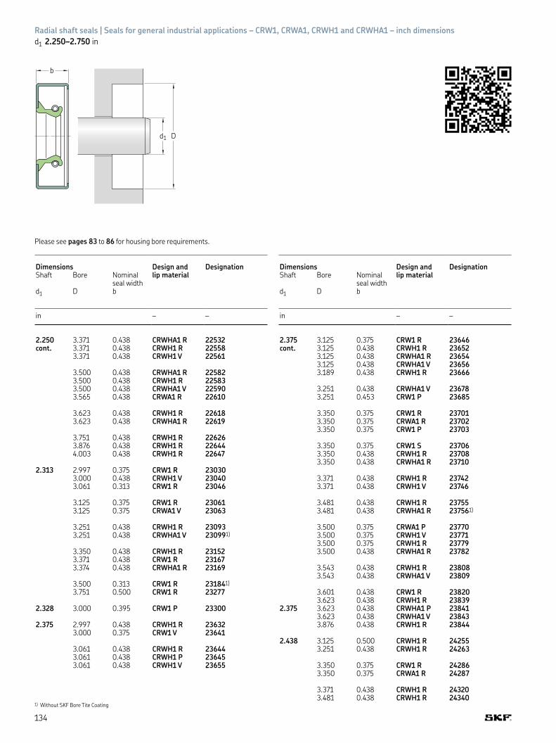
1) Without SKF Bore Tite Coating
b
d1 D
Please see pages 83 to 86 for housing bore requirements
Radial shaft seals | Seals for general industrial applications – CRW1, CRWA1, CRWH1 and CRWHA1 – inch dimensions
d1 2.250–2.750 in
Dimensions Design and DesignationShaft Bore Nominal
seal widthlip material
d1 D b
in – –
2.250 3.371 0.438 CRWHA1 R 22532cont. 3.371 0.438 CRWH1 R 22558
3.371 0.438 CRWH1 V 22561
3.500 0.438 CRWHA1 R 225823.500 0.438 CRWH1 R 225833.500 0.438 CRWHA1 V 225903.565 0.438 CRWA1 R 22610
3.623 0.438 CRWH1 R 226183.623 0.438 CRWHA1 R 22619
3.751 0.438 CRWH1 R 226263.876 0.438 CRWH1 R 226444.003 0.438 CRWH1 R 22647
2.313 2.997 0.375 CRW1 R 230303.000 0.438 CRWH1 V 230403.061 0.313 CRW1 R 23046
3.125 0.375 CRW1 R 230613.125 0.375 CRWA1 V 23063
3.251 0.438 CRWH1 R 230933.251 0.438 CRWHA1 V 230991)
3.350 0.438 CRWH1 R 231523.371 0.438 CRW1 R 231673.374 0.438 CRWHA1 R 23169
3.500 0.313 CRW1 R 231841)
3.751 0.500 CRW1 R 23277
2.328 3.000 0.395 CRW1 P 23300
2.375 2.997 0.438 CRWH1 R 236323.000 0.375 CRW1 V 23641
3.061 0.438 CRWH1 R 236443.061 0.438 CRWH1 P 236453.061 0.438 CRWH1 V 23655
Dimensions Design and DesignationShaft Bore Nominal
seal widthlip material
d1 D b
in – –
2.375 3.125 0.375 CRW1 R 23646cont. 3.125 0.438 CRWH1 R 23652
3.125 0.438 CRWHA1 R 236543.125 0.438 CRWHA1 V 236563.189 0.438 CRWH1 R 23666
3.251 0.438 CRWHA1 V 236783.251 0.453 CRW1 P 23685
3.350 0.375 CRW1 R 237013.350 0.375 CRWA1 R 237023.350 0.375 CRW1 P 23703
3.350 0.375 CRW1 S 237063.350 0.438 CRWH1 R 237083.350 0.438 CRWHA1 R 23710
3.371 0.438 CRWH1 R 237423.371 0.438 CRWH1 V 23746
3.481 0.438 CRWH1 R 237553.481 0.438 CRWHA1 R 237561)
3.500 0.375 CRWA1 P 237703.500 0.375 CRWH1 V 237713.500 0.375 CRWH1 R 237793.500 0.438 CRWHA1 R 23782
3.543 0.438 CRWH1 R 238083.543 0.438 CRWHA1 V 23809
3.601 0.438 CRW1 R 238203.623 0.438 CRWH1 R 23839
2.375 3.623 0.438 CRWHA1 P 238413.623 0.438 CRWHA1 V 238433.876 0.438 CRWH1 R 23844
2.438 3.125 0.500 CRWH1 R 242553.251 0.438 CRWH1 R 24263
3.350 0.375 CRW1 R 242863.350 0.375 CRWA1 R 24287
3.371 0.438 CRWH1 R 243203.481 0.438 CRWH1 R 24340
134

CRW1, CRWA1, CRWH1 and CRWHA1 – inch dimensions
Dimensions Design and DesignationShaft Bore Nominal
seal widthlip material
d1 D b
in – –
2.438 3.500 0.438 CRWH1 R 24370cont. 3.500 0.438 CRWH1 V 24372
3.543 0.438 CRWH1 R 24445
2.500 3.189 0.438 CRWH1 R 248813.189 0.438 CRWH1 V 248833.245 0.438 CRWH1 R 24889
3.251 0.375 CRW1 R 248973.251 0.375 CRWA1 R 248983.251 0.375 CRWA1 V 248993.251 0.438 CRWH1 R 24910
3.251 0.438 CRWHA1 R 249113.251 0.438 CRWH1 V 249143.251 0.438 CRWHA1 V 249163.251 0.500 CRW1 V 24913
3.350 0.438 CRWH1 R 249313.350 0.438 CRWHA1 R 24932
3.371 0.375 CRWHA1 R 249341)
3.371 0.438 CRWHA1 V 249363.371 0.438 CRWH1 R 24954
3.428 0.375 CRWA1 P 249493.428 0.375 CRWA1 R 24951
3.500 0.375 CRWA1 V 249713.500 0.438 CRW1 R 249803.500 0.438 CRWA1 R 249823.500 0.438 CRWH1 V 24984
3.500 0.438 CRWH1 R 249863.500 0.438 CRWHA1 R 249883.500 0.438 CRWH1 P 249893.500 0.438 CRWHA1 V 24990
3.502 0.406 CRW1 S 250823.543 0.438 CRWH1 R 250433.543 0.438 CRWHA1 P 250651)
3.544 0.433 CRWA1 V 25037
3.623 0.375 CRW1 R 250743.623 0.375 CRWA1 R 250753.623 0.375 CRWA1 V 250763.623 0.438 CRWH1 R 250711)
3.751 0.438 CRWH1 R 250911)
3.876 0.438 CRWH1 R 251003.876 0.469 CRWHA1 P 25102
4.003 0.375 CRWA1 R 251084.003 0.375 CRWA1 V 25110
2.563 3.481 0.500 CRWHA1 R 255613.500 0.438 CRWH1 R 25597
3.623 0.438 CRWH1 R 256413.623 0.469 CRWA1 P 25661
3.751 0.438 CRWH1 R 257133.751 0.438 CRWHA1 R 257143.751 0.438 CRWH1 V 25725
3.873 0.438 CRWHA1 R 257451)
3.876 0.438 CRWH1 R 25748
2.598 3.481 0.438 CRWHA1 P 25970
Dimensions Design and DesignationShaft Bore Nominal
seal widthlip material
d1 D b
in – –
2.607 3.350 0.375 CRWH1 P 25950
2.625 3.251 0.438 CRWH1 R 261103.350 0.375 CRW1 V 261223.350 0.375 CRW1 R 261233.350 0.375 CRWA1 R 261243.350 0.438 CRW1 R 261281)
3.371 0.438 CRWHA1 R 261533.374 0.438 CRWHA1 R 261413.481 0.438 CRWH1 R 26163
3.500 0.375 CRW1 V 261773.500 0.375 CRWA1 R 261863.500 0.438 CRWH1 R 261893.500 0.438 CRWHA1 R 26190
3.500 0.438 CRWA1 P 261913.543 0.438 CRWH1 R 26194
3.623 0.375 CRW1 V 262043.623 0.375 CRWA1 P 262203.623 0.375 CRW1 R 26237
2.625 3.623 0.375 CRWA1 R 262383.623 0.438 CRWH1 V 262083.623 0.438 CRWH1 R 262093.623 0.438 CRWHA1 R 26211
3.751 0.375 CRWA1 R 262843.751 0.438 CRWH1 R 26297
3.751 0.438 CRWHA1 R 262983.751 0.438 CRWHA1 V 26299
3.876 0.438 CRWH1 R 263283.936 0.438 CRWH1 R 26346
4.003 0.375 CRWA1 R 263544.003 0.438 CRWH1 R 26356
4.370 0.438 CRWHA1 R 263594.438 0.438 CRWH1 R 26368
2.688 3.751 0.438 CRWH1 R 267613.876 0.438 CRWH1 R 269214.003 0.469 CRWH1 R 26975
2.750 3.481 0.438 CRW1 R 272511)
3.500 0.375 CRW1 R 27268
3.500 0.375 CRWA1 R 272693.500 0.375 CRWA1 V 272723.500 0.438 CRWH1 R 272803.538 0.438 CRWH1 R 27284
3.543 0.438 CRWH1 P 272923.543 0.438 CRWH1 V 272933.543 0.438 CRWHA1 P 27295
3.623 0.438 CRWH1 V 273243.623 0.438 CRWH1 R 27334
3.751 0.438 CRW1 R 273613.751 0.438 CRWA1 R 273623.751 0.438 CRWH1 V 27365
3.751 0.438 CRWH1 R 273683.751 0.438 CRWHA1 R 273703.751 0.438 CRWA1 P 27377
135
A.1
Sea
ls for
gen
eral i
ndust
rial a
pplica
tions

1) Without SKF Bore Tite Coating
b
d1 D
Please see pages 83 to 86 for housing bore requirements
Radial shaft seals | Seals for general industrial applications – CRW1, CRWA1, CRWH1 and CRWHA1 – inch dimensions
d1 2.750–3.438 in
Dimensions Design and DesignationShaft Bore Nominal
seal widthlip material
d1 D b
in – –
2.750 3.765 0.438 CRWH1 R 27426cont.
3.876 0.433 CRWHA1 P 274523.876 0.438 CRWA1 R 274673.876 0.438 CRWH1 R 274703.876 0.438 CRWHA1 R 27471
3.936 0.438 CRWH1 R 275253.937 0.438 CRWA1 P 27526
4.003 0.375 CRWA1 V 275394.003 0.438 CRWH1 R 275414.003 0.438 CRWHA1 P 275651)
4.249 0.438 CRWH1 R 276004.249 0.438 CRWHA1 P 27601
4.331 0.500 CRWHA1 R 276254.500 0.469 CRWH1 R 28848
2.813 3.751 0.438 CRWH1 R 280353.876 0.438 CRWH1 R 28116
4.003 0.438 CRWH1 R 281754.249 0.313 CRW1 R 282704.249 0.438 CRWH1 R 282754.250 0.438 CRWH1 P 28276
2.844 3.939 0.500 CRWA1 R 284253.939 0.550 CRWHA1 R 28426
4.003 0.438 CRWH1 R 284644.003 0.500 CRWH1 V 28474
2.875 3.623 0.438 CRWH1 R 286543.623 0.438 CRWHA1 R 28655
3.751 0.375 CRWA1 R 286693.751 0.375 CRWA1 V 286703.751 0.438 CRWH1 R 28686
Dimensions Design and DesignationShaft Bore Nominal
seal widthlip material
d1 D b
in – –
2.875 3.751 0.438 CRWHA1 R 28687cont. 3.751 0.438 CRWH1 P 28697
3.751 0.438 CRWH1 V 286983.751 0.438 CRWHA1 V 28699
3.876 0.438 CRWH1 R 287453.876 0.438 CRWHA1 R 287463.876 0.438 CRWHA1 V 28748
4.003 0.375 CRWA1 R 287784.003 0.375 CRWA1 V 287794.003 0.438 CRWH1 R 287604.003 0.438 CRWHA1 R 28761
4.125 0.375 CRWH1 R 288174.331 0.438 CRWA1 P 28841
2.938 3.623 0.375 CRW1 R 292183.751 0.375 CRW1 R 292233.751 0.375 CRWA1 R 292243.751 0.375 CRWA1 V 29226
3.876 0.375 CRWHA1 R 292631)
3.876 0.375 CRWHA1 V 292623.937 0.438 CRWA1 P 29273
4.003 0.438 CRWH1 R 293164.003 0.438 CRWHA1 R 293931)
4.003 0.438 CRWA1 P 293504.004 0.433 CRWHA1 V 29383
4.125 0.375 CRWH1 R 291844.125 0.375 CRWHA1 R 293854.501 0.438 CRWH1 R 29465
3.000 3.500 0.375 CRW1 V 298413.751 0.375 CRW1 R 298651)
3.751 0.375 CRWA1 R 298663.751 0.375 CRWA1 P 29867
3.751 0.375 CRW1 V 298683.751 0.375 CRWA1 V 298703.751 0.438 CRWH1 R 298713.751 0.438 CRWHA1 R 29872
136

CRW1, CRWA1, CRWH1 and CRWHA1 – inch dimensions
Dimensions Design and DesignationShaft Bore Nominal
seal widthlip material
d1 D b
in – –
3.000 3.876 0.313 CRW1 V 29877cont. 3.876 0.438 CRWH1 R 29887
3.876 0.469 CRWH1 V 29891
4.003 0.375 CRW1 R 299064.003 0.375 CRWA1 R 299074.003 0.375 CRWA1 V 299124.003 0.375 CRWH1 P 29950
4.003 0.438 CRWHA1 P 299251)
4.003 0.438 CRWH1 R 299511)
4.003 0.438 CRWHA1 R 299524.003 0.438 CRWH1 V 29958
4.125 0.438 CRWH1 R 300004.125 0.438 CRWH1 V 30003
4.249 0.438 CRWH1 R 300331)
4.249 0.438 CRWHA1 P 300564.331 0.438 CRWH1 R 300604.376 0.438 CRWH1 R 30070
4.500 0.438 CRWH1 R 300874.500 0.438 CRWHA1 R 300954.501 0.438 CRWH1 V 300984.999 0.438 CRWH1 R 30125
3.125 3.811 0.355 CRW1 V 311323.811 0.355 CRW1 R 31135
4.003 0.375 CRWA1 R 311394.003 0.375 CRWHA1 V 311524.003 0.438 CRWH1 R 311474.003 0.438 CRWHA1 R 31148
3.125 4.125 0.375 CRW1 R 311774.125 0.375 CRWA1 V 311794.125 0.438 CRWHA1 P 311734.125 0.438 CRWHA1 S 311854.125 0.438 CRWH1 R 311891)
4.249 0.438 CRWH1 R 312274.249 0.438 CRWHA1 R 312284.249 0.438 CRWHA1 V 31237
4.376 0.438 CRWH1 R 312504.376 0.438 CRWHA1 P 31261
4.501 0.438 CRWH1 R 312694.626 0.438 CRWH1 R 312994.751 0.438 CRWH1 R 313274.999 0.438 CRWH1 R 313335.251 0.438 CRWH1 R 31353
3.150 3.946 0.394 CRW1 V 31511
3.188 4.249 0.438 CRWH1 R 317584.376 0.438 CRWH1 R 318254.501 0.438 CRWH1 R 318554.626 0.438 CRWH1 R 318704.999 0.438 CRWH1 R 31955
3.250 3.876 0.375 CRW1 P 323304.003 0.375 CRW1 R 323444.003 0.375 CRWA1 P 32347
Dimensions Design and DesignationShaft Bore Nominal
seal widthlip material
d1 D b
in – –
3.250 4.249 0.375 CRWA1 V 32392cont. 4.249 0.375 CRW1 R 32393
4.249 0.375 CRWA1 R 323954.249 0.438 CRWH1 P 323801)
4.249 0.438 CRWHA1 P 323854.249 0.438 CRWH1 R 323964.249 0.438 CRWHA1 R 323974.249 0.438 CRWH1 V 32403
3.250 4.376 0.438 CRWH1 R 324244.500 0.438 CRWA1 P 32448
4.501 0.375 CRW1 R 324774.501 0.438 CRWH1 R 325014.501 0.438 CRWHA1 R 32502
4.626 0.433 CRWHA1 R 325141)
4.626 0.438 CRWH1 R 32540
4.718 0.438 CRWH1 R 325554.751 0.438 CRWH1 R 32560
4.999 0.438 CRWH1 R 325824.999 0.438 CRWHA1 R 32583
3.313 4.125 0.438 CRWH1 R 330334.249 0.438 CRWH1 R 330734.500 0.438 CRWH1 R 331364.999 0.438 CRWH1 R 33306
3.375 4.125 0.375 CRW1 R 336454.125 0.375 CRWA1 V 34647
4.249 0.438 CRWHA1 R 336654.280 0.406 CRWA1 S 33654
4.376 0.375 CRWA1 V 336994.376 0.375 CRW1 R 337004.376 0.375 CRWA1 R 337014.376 0.438 CRWH1 R 337114.376 0.438 CRWHA1 R 33712
4.501 0.438 CRWA1 V 337334.501 0.438 CRWH1 R 33735
4.626 0.438 CRWH1 R 337724.626 0.438 CRWHA1 R 337734.626 0.438 CRWHA1 V 337754.686 0.438 CRWH1 R 338071)
4.999 0.438 CRWH1 R 338371)
5.251 0.438 CRWHA1 R 33866
3.438 4.249 0.375 CRW1 R 342564.501 0.375 CRWA1 R 342794.501 0.438 CRWH1 R 342824.501 0.438 CRWHA1 R 34283
4.626 0.438 CRWH1 R 343364.626 0.438 CRWHA1 R 34338
4.751 0.438 CRWA1 R 343794.756 0.438 CRWH1 R 343834.876 0.438 CRWH1 R 34398
4.999 0.438 CRWH1 R 344074.999 0.438 CRWHA1 R 34408
137
A.1
Sea
ls for
gen
eral i
ndust
rial a
pplica
tions

1) Without SKF Bore Tite Coating
b
d1 D
Please see pages 83 to 86 for housing bore requirements
Radial shaft seals | Seals for general industrial applications – CRW1, CRWA1, CRWH1 and CRWHA1 – inch dimensions
d1 3.438–4.500 in
Dimensions Design and DesignationShaft Bore Nominal
seal widthlip material
d1 D b
in – –
3.438 4.249 0.438 CRWHA1 V 34857cont. 4.376 0.375 CRW1 R 34860
4.376 0.375 CRWA1 R 34861
4.376 0.375 CRWA1 V 348664.376 0.433 CRWHA1 V 348694.376 0.438 CRWH1 R 348674.376 0.438 CRWHA1 R 34868
3.500 4.501 0.375 CRWA1 V 348834.501 0.375 CRW1 R 348864.501 0.375 CRWA1 R 348874.501 0.438 CRWH1 R 34888
4.501 0.438 CRWHA1 R 348894.501 0.438 CRWHA1 P 348911)
4.501 0.438 CRWH1 V 348924.626 0.438 CRWH1 R 34985
4.751 0.375 CRWA1 V 350394.751 0.375 CRWA1 P 350404.751 0.438 CRWH1 R 350124.751 0.438 CRWHA1 R 350204.751 0.625 CRWH1 R 35029
4.999 0.438 CRWA1 V 350804.999 0.438 CRWH1 R 350824.999 0.438 CRWHA1 P 35083
5.126 0.438 CRWH1 R 350865.126 0.438 CRWHA1 R 350955.251 0.438 CRWH1 R 35096
3.563 4.501 0.438 CRWH1 R 355564.626 0.438 CRWH1 R 355934.751 0.438 CRWH1 R 356494.876 0.438 CRWH1 R 356764.999 0.438 CRWH1 R 35716
3.625 4.376 0.375 CRWA1 V 361534.376 0.375 CRWA1 R 361554.376 0.375 CRWH1 R 361574.376 0.375 CRWH1 P 361584.501 0.375 CRW1 R 36166
Dimensions Design and DesignationShaft Bore Nominal
seal widthlip material
d1 D b
in – –
3.625 4.626 0.375 CRW1 R 36177cont. 4.626 0.375 CRWA1 V 36179
4.626 0.438 CRWH1 R 361854.626 0.438 CRWHA1 R 36186
4.751 0.438 CRWH1 R 362204.751 0.500 CRWA1 S 362344.876 0.438 CRWH1 R 36314
4.999 0.375 CRWA1 V 363594.999 0.375 CRWA1 R 363614.999 0.438 CRWH1 R 363634.999 0.438 CRWHA1 R 36364
5.251 0.375 CRWA1 R 363825.375 0.438 CRWHA1 R 36391
3.688 4.501 0.438 CRWHA1 R 367404.751 0.438 CRWH1 R 367704.999 0.438 CRWH1 R 36880
5.126 0.438 CRWA1 R 368955.626 0.438 CRWA1 R 36910
3.750 4.501 0.375 CRW1 R 373271)
4.501 0.375 CRW1 V 373284.501 0.469 CRWHA1 P 373304.502 0.469 CRWHA1 V 37332
4.750 0.438 CRWHA1 P 374034.751 0.375 CRW1 P 373874.751 0.375 CRW1 R 373884.751 0.375 CRWA1 R 37389
4.751 0.438 CRWA1 P 373904.751 0.438 CRWHA1 S 373954.751 0.438 CRWH1 R 373964.751 0.438 CRWH1 V 37405
4.876 0.438 CRWH1 R 374334.999 0.375 CRW1 V 375244.999 0.375 CRW1 R 37525
138

CRW1, CRWA1, CRWH1 and CRWHA1 – inch dimensions
Dimensions Design and DesignationShaft Bore Nominal
seal widthlip material
d1 D b
in – –
3.750 4.999 0.375 CRWA1 R 37526cont. 4.999 0.438 CRWH1 R 37532
4.999 0.438 CRWHA1 R 37533
5.251 0.438 CRWH1 R 375745.251 0.438 CRWH1 V 37577
3.875 4.751 0.375 CRW1 R 386464.751 0.375 CRWA1 R 386474.751 0.375 CRWA1 V 386494.751 0.438 CRWH1 R 38653
4.876 0.438 CRWHA1 R 386734.876 0.500 CRWH1 R 386694.876 0.500 CRWHA1 V 38678
4.999 0.375 CRW1 R 386914.999 0.375 CRWA1 R 386924.999 0.375 CRWA1 V 38694
5.126 0.438 CRWHA1 V 387025.126 0.438 CRWH1 R 387035.126 0.438 CRWHA1 R 38713
3.875 5.251 0.438 CRWH1 R 387305.251 0.438 CRWHA1 R 387315.251 0.438 CRWHA1 P 38739
5.376 0.438 CRWH1 R 387455.626 0.433 CRWHA1 R 387585.690 0.500 CRWH1 R 38774
3.938 4.876 0.438 CRWH1 R 392454.999 0.438 CRWH1 R 392754.999 0.438 CRWH1 V 392764.999 0.438 CRWH1 R 39277
5.126 0.472 CRWHA1 V 393045.251 0.438 CRWH1 R 393205.375 0.438 CRWH1 R 393505.501 0.438 CRWH1 R 39423
4.000 4.876 0.438 CRW1 R 398514.999 0.375 CRW1 P 398954.999 0.375 CRWA1 V 39921
4.999 0.375 CRW1 R 399224.999 0.375 CRWA1 R 399234.999 0.438 CRWHA1 P 399304.999 0.438 CRWH1 V 39932
4.999 0.438 CRWH1 R 399334.999 0.438 CRWHA1 R 399344.999 0.438 CRWH1 S 39935
5.126 0.438 CRWH1 R 399755.251 0.438 CRWH1 V 399965.251 0.438 CRWH1 R 399975.251 0.438 CRWA1 R 40000
5.310 0.500 CRWHA1 R 400205.376 0.438 CRWH1 R 400365.501 0.438 CRWH1 R 40049
4.000 5.626 0.375 CRWA1 R 400775.626 0.438 CRWH1 R 400785.751 0.438 CRWH1 R 40108
6.001 0.500 CRWH1 R 401386.250 0.500 CRWH1 R 40158
Dimensions Design and DesignationShaft Bore Nominal
seal widthlip material
d1 D b
in – –
4.125 4.999 0.438 CRWH1 R 411254.999 0.438 CRWH1 V 411261)
5.126 0.438 CRWH1 R 411705.126 0.438 CRWH1 V 41171
5.251 0.438 CRWH1 R 411855.251 0.438 CRWH1 V 41186
5.501 0.438 CRWH1 R 412655.501 0.438 CRWH1 V 41266
5.751 0.438 CRWH1 R 412876.001 0.438 CRWH1 R 413056.001 0.438 CRWH1 V 41307
4.250 5.251 0.375 CRWA1 R 424195.251 0.375 CRW1 S 42422
5.251 0.438 CRWH1 R 424265.251 0.438 CRWHA1 R 424275.251 0.438 CRWH1 V 42433
5.373 0.438 CRWA1 V 424745.376 0.438 CRWH1 R 42475
5.501 0.438 CRWH1 R 425285.626 0.438 CRWA1 R 425575.751 0.438 CRWH1 R 425735.876 0.500 CRWH1 V 42592
6.001 0.500 CRWH1 R 426166.126 0.500 CRWH1 R 426356.250 0.500 CRWH1 R 42644
4.313 5.501 0.433 CRWHA1 P 430725.501 0.438 CRWHA1 R 43073
4.331 5.626 0.472 CRWHA1 V 43345
4.375 5.376 0.438 CRWH1 R 436505.501 0.438 CRWH1 R 436915.751 0.438 CRWH1 R 43751
6.001 0.500 CRWH1 R 437716.063 0.500 CRWH1 R 5419741)
6.250 0.500 CRWH1 R 43820
4.438 5.501 0.500 CRWH1 R 442755.501 0.500 CRWH1 V 442765.751 0.500 CRWH1 R 44295
6.001 0.500 CRWH1 R 443206.250 0.500 CRWH1 R 44350
4.477 6.250 0.500 CRWH1 R 44630
4.500 5.251 0.438 CRWH1 R 449135.251 0.438 CRWHA1 V 44917
5.376 0.438 CRWH1 R 449205.376 0.438 CRWHA1 V 44926
5.501 0.375 CRW1 R 449595.501 0.375 CRWA1 R 449605.501 0.435 CRWH1 V 44980
5.501 0.438 CRWH1 R 449675.501 0.438 CRWHA1 R 449685.501 0.438 CRWH1 V 44973
139
A.1
Sea
ls for
gen
eral i
ndust
rial a
pplica
tions

1) Without SKF Bore Tite Coating
b
d1 D
Please see pages 83 to 86 for housing bore requirements
Radial shaft seals | Seals for general industrial applications – CRW1, CRWA1, CRWH1 and CRWHA1 – inch dimensions
d1 4.500–8.000 in
Dimensions Design and DesignationShaft Bore Nominal
seal widthlip material
d1 D b
in – –
4.500 5.626 0.438 CRWH1 R 45032cont. 5.626 0.438 CRWHA1 V 45033
5.751 0.375 CRWA1 V 450645.751 0.438 CRWH1 R 450695.751 0.438 CRWHA1 R 45070
6.001 0.500 CRWH1 R 451106.001 0.500 CRWHA1 R 451116.001 0.500 CRWHA1 V 45112
6.126 0.563 CRWH1 R 451406.250 0.500 CRWH1 R 45150
4.625 5.626 0.500 CRWH1 R 461445.626 0.500 CRWH1 V 46155
5.751 0.500 CRWH1 R 462005.751 0.500 CRWH1 S 46208
6.001 0.500 CRWH1 R 462856.250 0.500 CRWH1 R 46324
4.688 5.751 0.512 CRWH1 S 467705.751 0.512 CRWH1 R 468006.250 0.500 CRWH1 R 46950
4.750 5.749 0.438 CRW1 P 473755.751 0.500 CRW1 V 473795.751 0.500 CRWA1 V 473825.751 0.500 CRW1 R 47383
5.751 0.500 CRWH1 R 473945.751 0.500 CRWHA1 R 473955.875 0.500 CRWH1 R 47441
6.001 0.500 CRWH1 R 474746.001 0.500 CRWHA1 R 474756.001 0.500 CRW1 V 47481
6.250 0.500 CRWH1 R 475836.250 0.500 CRWHA1 V 47586
Dimensions Design and DesignationShaft Bore Nominal
seal widthlip material
d1 D b
in – –
4.813 5.751 0.563 CRWH1 P 480605.751 0.563 CRWH1 V 480625.751 0.563 CRWH1 S 48065
4.875 6.001 0.500 CRWH1 V 486926.001 0.500 CRWH1 R 486936.126 0.500 CRWH1 R 48726
6.250 0.500 CRWHA1 R 487686.250 0.500 CRWH1 R 487696.250 0.500 CRWH1 V 48772
4.921 6.375 0.500 CRWHA1 V 49274
4.938 6.001 0.500 CRWH1 R 492516.250 0.500 CRWH1 R 49301
5.000 6.001 0.500 CRWHA1 V 499276.001 0.500 CRWH1 R 499286.001 0.500 CRWHA1 R 499296.126 0.500 CRW1 V 49960
6.250 0.500 CRWH1 R 499666.250 0.500 CRW1 R 499846.250 0.500 CRWA1 R 49985
6.250 0.500 CRWH1 P 499901)
6.250 0.500 CRWH1 V 499916.250 0.500 CRWHA1 R 49998
6.375 0.500 CRWH1 R 501306.375 0.500 CRWHA1 R 50138
6.500 0.500 CRWH1 R 501486.500 0.500 CRWH1 V 50151
6.750 0.500 CRWH1 R 501686.750 0.500 CRWHA1 R 50172
5.063 6.126 0.500 CRWH1 R 506186.375 0.500 CRWH1 R 50650
5.125 6.126 0.500 CRWHA1 R 512406.126 0.500 CRW1 V 512436.126 0.500 CRW1 R 51247
140

CRW1, CRWA1, CRWH1 and CRWHA1 – inch dimensions
Dimensions Design and DesignationShaft Bore Nominal
seal widthlip material
d1 D b
in – –
5.125 6.250 0.500 CRWHA1 R 51252cont. 6.250 0.500 CRWA1 V 51253
6.375 0.500 CRWH1 R 512481)
6.375 0.500 CRWH1 V 51255
5.188 6.501 0.625 CRWH1 V 51852
5.250 6.001 0.375 CRW1 R 524406.001 0.500 CRWH1 V 52443
6.250 0.500 CRWH1 R 524456.250 0.500 CRWH1 V 52447
6.500 0.500 CRWH1 R 524886.500 0.500 CRWH1 V 52489
6.750 0.500 CRWH1 R 526486.750 0.500 CRWH1 V 52649
5.375 6.625 0.500 CRWH1 R 537016.625 0.500 CRWH1 V 53702
6.750 0.500 CRWH1 V 537716.750 0.500 CRWH1 R 53775
5.500 6.250 0.500 CRWA1 R 549256.500 0.500 CRWH1 R 549316.500 0.500 CRWH1 V 549346.500 0.500 CRWH1 P 54936
6.750 0.500 CRW1 R 549596.750 0.500 CRWA1 R 549606.750 0.500 CRWHA1 R 549716.750 0.500 CRWH1 R 549726.750 0.500 CRWH1 V 54974
5.512 6.693 0.472 CRWH1 V 5467471)
5.625 6.625 0.500 CRWH1 R 561016.625 0.500 CRWH1 V 56102
6.875 0.500 CRWH1 R 561366.875 0.500 CRWH1 V 56137
5.625 7.125 0.500 CRWHA1 R 561607.125 0.500 CRWHA1 V 56161
5.750 6.625 0.500 CRWH1 R 575056.625 0.500 CRW1 V 57506
6.750 0.500 CRWH1 R 575106.750 0.500 CRWH1 V 575226.751 0.500 CRWHA1 R 575091)
7.000 0.500 CRWH1 R 575217.000 0.500 CRWH1 V 575237.000 0.500 CRWHA1 R 57531
5.875 7.125 0.500 CRWH1 R 587167.125 0.500 CRWH1 V 587177.125 0.500 CRWHA1 R 58741
7.500 0.500 CRWH1 R 58760
6.000 6.750 0.500 CRWA1 V 599996.750 0.500 CRW1 V 60000
Dimensions Design and DesignationShaft Bore Nominal
seal widthlip material
d1 D b
in – –
6.000 7.500 0.500 CRWA1 R 60016cont. 7.500 0.500 CRWHA1 V 60026
7.500 0.500 CRWHA1 R 60028
6.125 7.125 0.625 CRWH1 R 612101)
7.625 0.625 CRWH1 R 612551)
7.625 0.625 CRWH1 P 612561)
6.250 7.252 0.500 CRWH1 R 624821)
7.500 0.500 CRWH1 R 624951)
7.500 0.500 CRWH1 V 62497
7.750 0.500 CRWH1 R 625357.875 0.625 CRWH1 R 62572
6.375 7.375 0.625 CRWH1 R 63700
7.875 0.563 CRWHA1 R 637347.875 0.625 CRWH1 R 637331)
6.500 7.500 0.500 CRWA1 R 649937.500 0.500 CRWH1 R 649941)
7.500 0.500 CRWH1 V 64998
8.000 0.500 CRW1 R 650218.000 0.500 CRWHA1 R 650371)
6.625 8.125 0.500 CRWH1 R 662411)
6.750 8.000 0.500 CRWH1 R 675158.250 0.500 CRWH1 R 675331)
6.875 8.375 0.500 CRWH1 R 687451)
7.000 8.000 0.630 CRWH1 R 700168.250 0.625 CRWH1 R 700281)
8.500 0.500 CRWA1 R 700808.500 0.625 CRWH1 R 700528.500 0.625 CRWHA1 R 700538.500 0.625 CRWHA1 V 70054
7.125 8.625 0.625 CRWH1 R 712451)
7.250 8.250 0.625 CRW1 R 725151)
8.750 0.625 CRWHA1 R 725398.750 0.750 CRWH1 P 725421)
9.055 0.625 CRWHA1 R 72570
7.375 8.875 0.625 CRWH1 R 737451)
7.500 8.500 0.625 CRWH1 R 750301)
9.000 0.625 CRWH1 R 750509.000 0.625 CRWHA1 P 75052
7.625 8.625 0.563 CRWH1 R 762151)
9.125 0.625 CRWH1 R 762551)
7.750 9.250 0.625 CRWH1 R 775401)
7.875 9.250 1.000 CRWHA1 R 787251)
9.375 0.625 CRWH1 R 787381)
8.000 9.000 0.625 CRWH1 R 799601)
9.000 0.625 CRWHA1 R 799611)
9.250 0.625 CRWH1 R 799971)
9.250 0.625 CRWHA1 R 799989.500 0.625 CRWH1 R 8001010.000 0.625 CRWHA1 R 800381)
141
A.1
Sea
ls for
gen
eral i
ndust
rial a
pplica
tions

1) Without SKF Bore Tite Coating
b
d1 D
Please see pages 83 to 86 for housing bore requirements
Radial shaft seals | Seals for general industrial applications – CRW1, CRWA1, CRWH1 and CRWHA1 – inch dimensions
d1 8.125–12.250 in
Dimensions Design and DesignationShaft Bore Nominal
seal widthlip material
d1 D b
in – –
8.125 10.125 0.625 CRWH1 R 812451)
10.125 0.625 CRWHA1 R 812461)
8.250 9.250 0.625 CRWH1 R 825101)
9.252 0.500 CRWH1 R 825279.500 0.578 CRW1 R 5414051)
10.250 0.625 CRWH1 R 825601)
8.500 9.750 0.625 CRWH1 R 8500210.000 0.625 CRWH1 R 850091)
10.500 0.625 CRWH1 R 850151)
10.625 0.625 CRWHA1 R 850851)
8.625 10.625 0.625 CRWH1 R 862601)
8.750 10.750 0.625 CRWH1 R 875411)
8.875 10.125 0.625 CRWH1 R 887101)
10.875 0.625 CRWH1 R 887601)
9.000 10.000 0.625 CRWH1 R 900061)
11.000 0.625 CRWH1 R 900361)
9.250 11.250 0.625 CRWHA1 R 9253612.750 0.625 CRWHA1 R 925701)
12.750 1.250 CRWHA1 R 925741)
9.500 10.500 0.438 CRW1 R 9504811.500 0.625 CRW1 R 95062
9.625 11.625 0.625 CRWH1 R 962451)
11.125 0.625 CRWH1 R 975421)
11.250 0.625 CRWH1 R 975451)
11.750 0.625 CRWH1 R 975501)
10.000 11.252 0.625 CRWHA1 R 1000441)
12.000 0.625 CRWH1 R 1000511)
12.000 0.625 CRWA1 R 100075
10.250 11.250 0.563 CRWH1 R 1025201)
12.250 0.625 CRWH1 R 1025401)
Dimensions Design and DesignationShaft Bore Nominal
seal widthlip material
d1 D b
in – –
10.500 11.750 0.625 CRWH1 R 1050101)
12.500 0.625 CRWH1 R 1050511)
10.750 12.750 0.625 CRWH1 R 1075511)
11.000 12.250 0.625 CRWHA1 R 1100301)
13.000 0.625 CRWH1 R 1100511)
11.375 13.000 0.625 CRW1 R 1137401)
11.500 13.000 0.625 CRWH1 R 1150211)
13.500 0.625 CRWH1 R 1150411)
12.000 14.000 0.625 CRW1 R 1200601)
12.250 13.375 0.625 CRWH1 R 1225551)
13.813 0.625 CRW1 R 1225801)
14.250 1.000 CRWHA1 R 1225901)
142

CRW1, CRWA1, CRWH1 and CRWHA1 – inch dimensions
143
A.1
Sea
ls for
gen
eral i
ndust
rial a
pplica
tions

Main features
CRW5 and CRWA5 seals are designed to
withstand moderate pressure differentials.
They have an SKF Wave lip to reduce heat
generation and a metal outside diameter for
easy installation and a irm and accurate it
in the housing bore. See pages 68 and 69
for more information on SKF Wave lip
design. Most of them have SKF Bore Tite
Coating on the outside diameter. The CRWA5
seals have an auxiliary lip, providing addi-
tional contaminant exclusion ability. A shoul-
der or retaining ring should be used at the
low-pressure side of the seal to prevent it
from being pressed out of the housing bore.
Design
• CRW5: Seal with one steel case, SKF Wave
lip and a carbon steel garter spring.
• CRWA5: Seal with one steel case, SKF
Wave lip, a carbon steel garter spring and
an auxiliary, contacting lip.
The CRW5 and CRWA5 seals are available in
inch sizes with sealing lips made of either
nitrile rubber or the SKF luoro rubber com-
pound SKF Duralife. Other materials are also
available on request.
See matrix 1 on pages 104 and 105 for
permissible operating conditions.
CRW5 and CRWA5 seals
CRW5
CRWA5
Fig. 7
Fig. 8
144144
Radial shaft seals | Seals for general industrial applications

Product tables
1) Without SKF Bore Tite Coating
b
d1 D
Please see pages 83 to 86 for housing bore requirements
CRW5 and CRWA5 – inch dimensions
d1 0.313–1.000 in
Dimensions Design and DesignationShaft Bore Nominal
seal widthlip material
d1 D b
in – –
0.313 0.686 0.313 CRWA5 R 30941)
0.749 0.250 CRWA5 R 31011)
0.749 0.250 CRWA5 V 31031)
0.999 0.313 CRWA5 R 31711)
0.375 0.749 0.250 CRW5 R 36891)
1.124 0.375 CRW5 V 3807
0.500 0.875 0.313 CRWA5 R 49400.875 0.313 CRWA5 V 4941
0.999 0.250 CRWA5 V 49910.999 0.313 CRWA5 R 4996
1.124 0.250 CRWA5 R 50691.124 0.250 CRWA5 V 5072
0.625 0.999 0.250 CRWA5 R 61511.124 0.250 CRW5 R 61911.124 0.374 CRWA5 V 62311.124 0.375 CRWA5 R 62291.126 0.250 CRW5 R 6242
1.250 0.313 CRWA5 R 62801)
1.250 0.313 CRWA5 V 62851)
1.375 0.250 CRW5 P 63711.375 0.375 CRWA5 R 63881.500 0.313 CRW5 V 6393
0.750 1.250 0.250 CRWA5 R 74341.250 0.375 CRWA5 R 74491.375 0.250 CRWA5 V 7509
0.875 1.250 0.250 CRWA5 V 86341.375 0.250 CRWA5 R 86601.375 0.250 CRWA5 V 86651.497 0.313 CRWA5 V 8694
0.984 1.596 0.250 CRWA5 R 97001.752 0.313 CRWA5 V 9805
Dimensions Design and DesignationShaft Bore Nominal
seal widthlip material
d1 D b
in – –
1.000 1.375 0.250 CRWA5 R 98141.499 0.250 CRWA5 R 98431.499 0.250 CRW5 R 98551)
1.499 0.250 CRWA5 V 9858
1.500 0.250 CRWA5 R 98631.752 0.313 CRWA5 R 99672.000 0.313 CRWA5 R 10131
145
A.1
Sea
ls for
gen
eral i
ndust
rial a
pplica
tions

Main features
HDW1 seals are heavy-duty SKF Wave lip
seals, designed for use in grease or oil lubri-
cated appli cations. The seals are produced as
a standard with a heavy-duty seal body, SKF
Bore Tite Coating on the metal outside
diameter, SKF Wave lip in nitrile rubber,
and a carbon steel garter spring.
The rigid seal body can withstand operat-
ing pressures up to 0,24 MPa (35 psi),
dynamic, and 0,34 MPa (50 psi), static, while
withstanding shaft speeds up to 25 m/s
(4 900 ft/min) at shaft diameters < 203 mm
(8 in).
The HDW1 seals are available in inch
sizes.
HDW1 seals
HDW1
Fig. 9
146146
Radial shaft seals | Seals for general industrial applications

Product tables
1) Stainless steel garter spring
Please see pages 83 to 86 for housing bore requirements
b
d1 D
HDW1 – inch dimensions
d1 5.000–7.938 in
Dimensions Design and DesignationShaft Bore Nominal
seal widthlip material
d1 D b
in – –
5.000 6.125 0.500 HDW1 R 499517.125 0.500 HDW1 R 50186
5.063 6.125 0.500 HDW1 R 50620
5.125 6.625 0.500 HDW1 R 512777.000 0.500 HDW1 R 51330
5.188 6.250 0.500 HDW1 R 51800
5.250 6.750 0.500 HDW1 R 526517.125 0.500 HDW1 R 52655
5.313 6.375 0.500 HDW1 R 53100
5.438 6.625 0.500 HDW1 R 54300
5.875 6.875 0.500 HDW1 R 587091)
7.000 0.500 HDW1 R 58710
5.938 7.000 0.500 HDW1 R 59300
6,000 7.250 0.500 HDW1 R 60009
6.063 7.500 0.500 HDW1 R 60650
6.125 7.125 0.500 HDW1 R 612157.250 0.500 HDW1 R 612307.375 0.500 HDW1 R 61235
6.250 7.250 0.500 HDW1 R 62480
6.375 7.500 0.500 HDW1 R 63717
6.438 7.500 0.500 HDW1 R 64330
6.625 7.625 0.500 HDW1 R 662177.750 0.500 HDW1 R 662197.875 0.500 HDW1 R 662228.000 0.500 HDW1 R 66230
6.750 7.750 0.500 HDW1 R 675108.750 0.500 HDW1 R 67600
Dimensions Design and DesignationShaft Bore Nominal
seal widthlip material
d1 D b
in – –
6.875 8.250 0.500 HDW1 R 687308.500 0.500 HDW1 R 68760
7.125 8.250 0.500 HDW1 R 71220
7.375 8.375 0.500 HDW1 R 737208.500 0.500 HDW1 R 73730
7.500 8.750 0.500 HDW1 R 750469.250 0.500 HDW1 R 75069
7.625 8.875 0.500 HDW1 R 76225
7.750 8.750 0.500 HDW1 R 77506
7.875 8.875 0.500 HDW1 R 78710
7.938 9.125 0.500 HDW1 R 79620
147
A.1
Sea
ls for
gen
eral i
ndust
rial a
pplica
tions

Main features
All CRS seals are designed with a metal case
and a conventional spring-loaded sealing lip
Some of them have a sealant on the outside
diameter to compensate for imperfections in
the housing bore
Design
• CRS1: Seal with a single steel case, a con-
ventional sealing lip and a carbon steel
garter spring
• CRSA1: Seal with a single steel case, a
conventional sealing lip, a carbon steel
garter spring and a contacting auxiliary lip
• CRSH1: Seal with a double steel case, a
conventional sealing lip and a carbon steel
garter spring
• CRSHA1: Seal with a double steel case, a
conventional sealing lip, a carbon steel
garter spring and a contacting auxiliary lip
CRS seals are available with sealing lips
made of nitrile rubber for general-purpose
appli cations and of luoro rubber, providing
improved high temperature and chemical
resistance
See matrix 1 on pages 104 and 105 for
permissible operating conditions
CRS1, CRSH1, CRSA1 and CRSHA1 seals
CRS1 CRSH1
CRSA1 CRSHA1
Fig. 12
Fig. 10
Fig. 13
Fig. 11
148148
Radial shaft seals | Seals for general industrial applications

Product tables
1) Sealant on outside diameter
CRS1, CRSH1, CRSA1 and CRSHA1 – metric dimensions
d1 12–80 mm
Dimensions Design and DesignationShaft Bore Nominal
seal widthlip material
d1 D b
mm – –
12 20 5 CRSA1 R 12×20×5 CRSA1 R
13 28 7 CRS1 R 13×28×7 CRS1 R
19 37 10 CRS1 V 19×37×10 CRS1 V
20 30 5 CRS1 R 20×30×5 CRS1 R30 7 CRS1 V 20×30×7 CRS1 V32 7 CRS1 V 20×32×7 CRS1 V42 7 CRS1 V 20×42×7 CRS1 V
22 32 7 CRS1 V 22×32×7 CRS1 V
24 38 10 CRS1 R 24×38×10 CRS1 R
25 32 7 CRSA1 R 25×32×7 CRSA1 R47 10 CRSA1 V 25×47×10 CRSA1 V52 7 CRS1 R 25×52×7 CRS1 R
26 35 7 CRS1 R 26×35×7 CRS1 R42 8 CRS1 R 26×42×8 CRS1 R
27 37 7 CRS1 V 27×37×7 CRS1 V41 10 CRSH1 R 27×41×10 CRSH1 R
28 62 12 CRSH1 R 28×62×12 CRSH1 R
30 45 8 CRS1 V 30×45×8 CRS1 V52 9 CRSH1 R 30×52×9 CRSH1 R
32 46 8 CRS1 R 32×46×8 CRS1 R
34 52 10 CRS1 R 34×52×10 CRS1 R54 11 CRS1 R 34×54×11 CRS1 R
35 64 8 CRSA1 P 35×64×8 CRSA1 P65 12 CRSA1 R 35×65×12 CRSA1 R
36 46 9 CRS1 R 36×46×9 CRS1 R56 10 CRS1 R 36×56×10 CRS1 R
37 55 10 CRSH1 R 37×55×10 CRSH1 R
Dimensions Design and DesignationShaft Bore Nominal
seal widthlip material
d1 D b
mm – –
40 55 10 CRS1 R 40×55×10 CRS1 R60 10 CRSA1 R 40×60×10 CRSA1 R
42 62 10 CRS1 R 42×62×10 CRS1 R
43 62 10 CRSH1 R 43×62×10 CRSH1 R
45 58 9 CRSA1 R 45×58×9 CRSA1 R62 7 CRSA1 R 45×62×7 CRSA1 R
48 70 9 CRSA1 R 48×70×9 CRSA1 R
50 62 7 CRS1 R 50×62×7 CRS1 R62 10 CRS1 R 50×62×10 CRS1 R85 13 CRSH1 R 50×85×13 CRSH1 R
54 72 10 CRSA1 R 54×72×10 CRSA1 R80 10 CRSH1 R 54×80×10 CRSH1 R
57 72 10 CRSH1 R 57×72×10 CRSH1 R
58 85 13 CRSH1 R 58×85×13 CRSH1 R
59 75 10 CRSA1 R 59×75×10 CRSA1 R
60 70 7 CRS1 R 60×70×7 CRS1 R78 9 CRS1 R 60×78×9 CRS1 R1)
80 10 CRSHA1 R 60×80×10 CRSHA1 R90 10 CRSH1 R 60×90×10 CRSH1 R
62 75 10 CRS1 R 62×75×10 CRS1 R
66 80 8,9 CRSHA1 R 66×80×9 CRSHA1 R85 10 CRSHA1 R 66×85×10 CRSHA1 R90 13 CRSH1 R 66×90×13 CRSH1 R
68 85 10 CRS1 R 68×85×10 CRS1 R
74 100 13 CRSH1 R 74×100×13 CRSH1 R
75 115 13 CRSH1 R 75×115×13 CRSH1 R
80 100 13 CRSA1 R 80×100×13 CRSA1 R125 13 CRSH1 R 80×125×13 CRSH1 R
b
d1 D
Please see pages 83 to 86 for housing bore requirements.
149149
C
D
E
F
G
H
I
Sea
ls for
gen
eral i
ndust
rial a
pplica
tions
A.1

Please see pages 83 to 86 for housing bore requirements
b
d1 D
Radial shaft seals | Seals for general industrial applications – CRS1, CRSH1, CRSA1 and CRSHA1 – metric dimensions
d1 85–260 mm
Dimensions Design and DesignationShaft Bore Nominal
seal widthlip material
d1 D b
mm – –
154 175 13 CRSA1 R 154×175×13 CRSA1 R
160 185 13 CRSA1 V 160×185×13 CRSA1 V
168 200 15 CRSH1 R 168×200×15 CRSH1 R
170 190 15 CRSH1 R 170×190×15 CRSH1 R
180 200 12 CRS1 R 180×200×12 CRS1 R215 16 CRS1 R 180×215×16 CRS1 R220 16 CRSA1 R 180×220×16 CRSA1 R
190 215 16 CRSH1 R 190×215×16 CRSH1 R
195 230 15 CRSH1 R 195×230×15 CRSH1 R
200 250 15 CRSH1 R 200×250×15 CRSH1 R
260 300 20 CRS1 R 260×300×20 CRS1 R
Dimensions Design and DesignationShaft Bore Nominal
seal widthlip material
d1 D b
mm – –
85 100 9 CRS1 R 85×100×9 CRS1 R
88 110 13 CRSH1 R 88×110×13 CRSH1 R
90 125 13 CRSH1 R 90×125×13 CRSH1 R
95 110 9 CRS1 R 95×110×9 CRS1 R
100 120 13 CRSH1 R 100×120×13 CRSH1 R
105 125 12 CRS1 R 105×125×12 CRS1 R
107 123 11 CRSA1 R 107×123×11 CRSA1 R
108 130 13 CRSH1 R 108×130×13 CRSH1 R
113 140 13 CRSH1 R 113×140×13 CRSH1 R
115 160 15 CRSH1 R 115×160×15 CRSH1 R
120 150 15 CRSH1 R 120×150×15 CRSH1 R
125 146 14 CRSA1 P 125×146×14 CRSA1 P
126 147 11 CRSA1 R 126×147×11 CRSA1 R
130 150 10 CRSA1 R 130×150×10 CRSA1 R150 14 CRSA1 R 130×150×14 CRSA1 R155 10 CRSH1 R 130×155×10 CRSH1 R160 13 CRS1 R 130×160×13 CRS1 R160 13 CRSA1 R 130×160×13 CRSA1 R165 13 CRSH1 R 130×165×13 CRSH1 R
135 160 13 CRSH1 R 135×160×13 CRSH1 R170 15 CRSH1 R 135×170×15 CRSH1 R
138 152 12 CRSA1 R 138×152×12 CRSA1 R
145 164 14 CRSA1 R 145×164×14 CRSA1 R175 14 CRS1 R 145×175×14 CRS1 R
150 170 15 CRSH1 R 150×170×15 CRSH1 R180 13 CRSH1 R 150×180×13 CRSH1 R200 15 CRSH1 R 150×200×15 CRSH1 R
150

1) Sealant on outside diameter
CRS1, CRSH1, CRSA1 and CRSHA1 – inch dimensions
d1 0.531–1.875 in
Dimensions Design and DesignationShaft Bore Nominal
seal widthlip material
d1 D b
in – –
0.531 1.124 0.313 CRSA1 R 5334
0.594 1.250 0.313 CRSA1 R 59501.375 0.313 CRSA1 R 59661)
0.669 1.339 0.311 CRSA1 P 6992
0.709 1.339 0.315 CRSA1 P 7089
0.781 1.752 0.313 CRSHA1 R 8213
0.844 1.828 0.313 CRSA1 R 8485
0.945 1.575 0.315 CRS1 R 9515
0.969 2.048 0.375 CRS1 R 96881)
1.125 2.835 0.375 CRSA1 R 114051)
2.875 0.469 CRSH1 R 114101)
1.156 2.125 0.438 CRSH1 R 115661)
1.219 2.000 0.438 CRSH1 R 121311)
1.250 2.561 0.500 CRSH1 R 126552.713 0.469 CRSH1 R 126601)
3.156 0.500 CRSH1 R 12678
1.301 2.000 0.438 CRSA1 P 12905
1.313 1.874 0.375 CRSA1 R 130271)
2.000 0.313 CRSA1 R 130371)
2.106 0.375 CRSA1 R 130841)
2.996 0.500 CRSH1 R 132751)
1.328 2.312 0.433 CRS1 R 134191)
1.362 2.191 0.250 CRS1 P 13500
1.375 2.750 0.500 CRSH1 R 139061)
3.000 0.500 CRSHA1 R 139373.125 0.500 CRSH1 R 139363.350 0.469 CRSH1 R 139341)
Dimensions Design and DesignationShaft Bore Nominal
seal widthlip material
d1 D b
in – –
1.399 2.292 0.469 CRSA1 R 139921)
2.292 0.500 CRSA1 R 139901)
1.414 2.250 0.250 CRSHA1 R 140351)
1.469 2.374 0.375 CRSA1 R 146411)
1.491 2.191 0.250 CRSA1 R 14780
1.500 2.996 0.500 CRSH1 R 152403.000 0.375 CRSA1 R 15241
1.524 2.374 0.500 CRSH1 R 15343
1.563 2.716 0.469 CRSH1 R 157481)
1.618 2.575 0.500 CRSA1 R 164041)
1.625 2.437 0.469 CRSHA1 R 161212.835 0.469 CRSH1 R 163863.062 0.500 CRSH1 R 164311)
3.251 0.500 CRSH1 R 164401)
1.656 2.502 0.500 CRSH1 R 165321)
1.688 2.374 0.313 CRSA1 R 166692.835 0.469 CRSA1 R 16960
1.705 3.084 0.500 CRS1 R 17053
1.719 2.623 0.500 CRSH1 R 171361)
1.750 2.328 0.438 CRS1 R 172573.154 0.313 CRS1 R 177263.937 0.313 CRSA1 R 177711)
1.781 2.750 0.500 CRSH1 R 178472.758 0.500 CRSH1 R 178511)
1.844 2.502 0.375 CRSA1 R 184121)
2.750 0.375 CRSA1 R 184461)
1.875 3.125 0.313 CRSA1 R 188791)
b
d1 D
151
A.1
Sea
ls for
gen
eral i
ndust
rial a
pplica
tions

1) Sealant on outside diameter
Please see pages 83 to 86 for housing bore requirements
b
d1 D
Radial shaft seals | Seals for general industrial applications – CRS1, CRSH1, CRSA1 and CRSHA1 – inch dimensions
d1 1.889–7.000 in
Dimensions Design and DesignationShaft Bore Nominal
seal widthlip material
d1 D b
in – –
3.298 4.125 0.563 CRSA1 R 328151)
3.469 4.626 0.625 CRSA1 R 34700
3.500 5.751 0.563 CRSH1 R 351111)
3.504 4.173 0.354 CRSA1 V 35120
3.813 4.999 0.469 CRSH1 R 381605.251 0.469 CRSH1 R 382201)
3.875 5.501 0.500 CRSHA1 R 387491)
5.751 0.563 CRSH1 R 38810
3.898 4.680 0.370 CRSA1 VR 38770
4.188 4.999 0.469 CRSHA1 R 417515.251 0.469 CRSH1 R 417615.751 0.500 CRSHA1 R 41833
4.313 5.751 0.500 CRSH1 R 43231
4.563 5.751 0.500 CRSHA1 R 455506.250 0.500 CRSH1 R 45560
5.000 7.000 0.500 CRSHA1 R 501857.500 0.500 CRSHA1 R 50195
5.125 6.500 0.500 CRSHA1 R 51276
5.313 6.500 0.500 CRSHA1 R 53151
5.375 6.374 0.500 CRSHA1 R 536881)
6.499 0.563 CRSH1 R 53692
5.500 6.626 0.563 CRSHA1 R 549496.876 0.563 CRSHA1 R 551577.501 0.563 CRSH1 R 55179
5.750 6.876 0.563 CRSHA1 R 575197.126 0.563 CRSHA1 R 575787.502 0.563 CRSHA1 R 57584
Dimensions Design and DesignationShaft Bore Nominal
seal widthlip material
d1 D b
in – –
1.889 3.110 0.688 CRSA1 P 18983
1.890 2.874 0.276 CRSA1 P 18979
1.906 3.189 0.313 CRSA1 P 19062
1.938 2.762 0.500 CRSA1 R 192731)
2.825 0.500 CRSH1 P 192743.751 0.500 CRSH1 R 194661)
1.969 2.638 0.354 CRSA1 R 196282.686 0.500 CRSH1 R 196152.742 0.500 CRSH1 P 196202.875 0.469 CRSH1 R 19643
2.008 2.953 0.354 CRSA1 P 20012
2.063 2.875 0.375 CRSA1 R 5500851)
2.125 3.623 0.469 CRSA1 P 21379
2.145 3.188 0.469 CRSH1 R 21538
2.188 3.623 0.500 CRSHA1 R 21950
2.432 3.070 0.227 CRSA1 P 24110
2.563 3.500 0.500 CRSHA1 P 25587
2.648 3.812 0.500 CRS1 R 26877
2.750 4.125 0.438 CRS1 P 275761)
4.125 0.563 CRSA1 R 27577
2.875 3.434 0.294 CRSA1 R 286461)
2.913 3.543 0.394 CRS1 P 29105
3.125 3.936 0.512 CRSA1 V 311441)
3.250 3.876 0.375 CRSA1 V 323321)
4.125 0.563 CRSH1 R 323621)
152

1) Sealant on outside diameter
CRS1, CRSH1, CRSA1 and CRSHA1 – inch dimensions
Dimensions Design and DesignationShaft Bore Nominal
seal widthlip material
d1 D b
in – –
6.000 7.002 0.500 CRSHA1 R 600061)
6.062 6.772 0.551 CRSA1 R 60620
6.125 7.502 0.563 CRSHA1 R 612481)
6.188 7.500 0.563 CRSH1 P 61740
7.000 8.375 0.625 CRSHA1 R 70034
153
A.1
Sea
ls for
gen
eral i
ndust
rial a
pplica
tions

Main features
Radial shaft seals with one or more PTFE
sealing lip(s) are designed to withstand
aggressive environ ments, high tempera-
tures, high pressures and dry running that
trad itional radial shaft seals made of elasto-
meric sealing lip materials cannot withstand
Many of the PTFE compounds are FDA
approved Main advantages of PTFE seals
include:
• High chemical resistance
• Withstand speeds up to 30 m/s
(5 900 ft/min)
• Wide operating temperature range,
–70 to +250 °C (–95 to +480 °F)
• Withstand pressures up to 3,5 MPa
(500 psi)
• Withstand dry running
Assortment
The proiles shown here are a selection of
the most commonly used SKF seal designs
with sealing lips made of PTFE. They can be
installed in existing housing grooves where
traditional radial seals are used, provided
that the grooves are manufactured in
accordance with inter national standards.
There are two main executions of PTFE
seals: those with a metal case and those
without a metal case. The metal case can be
made of steel, aluminium or any of the
stainless steel materials SS 304, SS 316 and
SS 316 TI. The PTFE ma terial should be
selected based on the needs of the
application.
PTFE seals without a metal case can be
designed with an O-ring in the outside
diameter groove to provide static sealing
ability. Both the PTFE and O-ring material
can be selected to meet the demands of dif-
ferent operating conditions, e.g. in the food
industry to enable disassembly of the equip-
ment for cleaning.
PTFE materials
The selection of sealing materials typically
requires a compromise between advantages
and disadvantages. There are hundreds of
different PTFE materials with a variety of
illers. Common illers include glass ibre,
carbon, graphite, molyb denum disulphide,
metal oxides and various polymers. Each
possesses different properties, appropriate
for different applications and service condi-
tions. Common to all illed PTFE materials
are their improved resistance to wear and
deformation.
Unilled PTFE provides, in most cases, a
lower coeficient of friction than a illed PTFE
material and the lowest degree of wear of
the seal counterface. However, a sealing lip
made of an unilled PTFE material has lim-
ited resistance to wear and deformation
under load.
The PTFE materials that SKF most often
recommends are listed in table 3 on page
156.
In addition to PTFE-based compounds, SKF
also offers radial shaft seals in other modi-
ied plastics, some of which are listed in
table 4 on page 157.
Selecting the appropriate material for the
metal case and the O-ring(s) is also of sig-
nii cant importance to achieving satisfactory
sealing performance. Contact SKF for more
information.
PTFE radial shaft seals
SL SLA SLX SLS YSLE
154154
Radial shaft seals | Seals for general industrial applications

Installation
Special care must be taken during handling
and installation of PTFE seals For more
information, refer to pages 96 and 97
Size range and availability
The majority of PTFE radial shaft seals from
SKF are made to order to meet the demands
of each application There are, however, cer-
tain standard sizes within the ranges of
approximately 6 to 200 mm (0.250 to 8 in)
shaft diameter and approximately 16 to
230 mm (0.630 to 9 in) bore diameter.
Contact SKF for more information regarding
designs and sizes.
DL DLA YNSLE YSL
PTFE radial shaft seals
155155
C
D
E
F
G
H
I
Sea
ls for
gen
eral i
ndust
rial a
pplica
tions
A.1

Table 3
Material family Description Shaft hardness recommended 1)
PTFE, unilled “Virgin” PTFE. FDA approved. Low-friction material. Used for general non-pressure applications on shafts with low hard-ness value. Excellent for cryogenics.
A
PTFE + glass FDA approved. Glass can be in the form of beads or ibres. Glass is exceptionally strong and prolongs the life of the base PTFE. Due to its inherent hardness, it also adds an abrasive property and is not recommended on low-hardness shafts.
C
PTFE + MoS2 Molybdenum disulphide (MoS2) adds wear resistance to the base PTFE. Not as abrasive as glass.
C
PTFE + glass + MoS2 Improved elongation characteristics and less abrasive to running surfaces compared to PTFE + glass.
C
PTFE + carbon Carbon can be in the form of various grades of ibres or graph-ite powder, either natural or synthetic. Carbon is an excellent natural lubricant and provides wear resistance to enhance the low-friction base PTFE material. Increased percentage of carbon will increase the wear, creep, and extrusion resistance and improve performance in steam and chemical service at elevated temperatures and pressures.
A, B, C
PTFE + carbon + MoS2 Excellent wear rate in non-lubricated services at high temperatures.
B, C
PTFE + bronze Suitable for high-speed dynamic sealing of hydraulic media. Should not be used in chemical service, which could attack the bronze.
PTFE + bronze + MoS2 High degree of wear and extrusion resistance in high-pressure applications.
PTFE + polymer Polymers, such as polyoxybenzoate, polyimide and many others improve creep and wear resistance.
A, B, C
PTFE + organic pigment FDA and / or USDA 3A approved.
1) Material selection recommendations for counterface hardness ratings (Rockwell C scale) combined with surface speed.For material selection, please see table 5 on page 157
156156
Radial shaft seals | Seals for general industrial applications

Table 4
Modiied plastic materials
UHMWPE Ultra-high molecular weight polyethylene. Signiicantly improved wear and abrasion resistance compared to PTFE-based materials in non-lubricated or abrasive media. FDA and USDA 3A approved. Fair media compatibility, limited to approxi-mately 90 °C (195 °F).
PA Polamide. Improved strength, limited media compatibility and temperature resistance. Hygroscopic. Used for plain bearings, bushings, back-up rings and some seals.
POM Polyoxymethylene (a.k.a. polyacetal or just acetal). Similar to nylon but with signiicantly reduced water-absorption proper-ties. Some grades are FDA and USDA 3A compliant. Typically used for plain bearings, bushings, and back-up rings.
PETP Polyethylene-therephthalate. Similar to POM but offers improved media compatibility and improved wear resistance.
PEEK Polyetheretherketone. Similar strength properties as PA and POM but with very good media compatibility and signiicantly better temperature properties. Some grades are FDA and USDA 3A compliant. Used for plain bearings, bushings, back-up rings and some seals.
PPS Polyphenylene sulphide. Similar strength properties and chemical compatibility as PEEK-based compounds but offers mproved wear resistance. Has better temperature capabilities than PA or POM materials but not as good as PEEK. Adding illers can create a “bearing-grade” PPS for high-performance applications.
PI Polyimide. Exceptional mechanical, thermal and chemical resistance properties.
Table 5
Material selection with shaft hardness + velocity
Surface speed < 30 HRC 45 HRC ≥ 58 HRC
Low A or B A, B, C A, B, C
Medium A A, B A, B, C
High A A, B A, B
PTFE radial shaft seals
157157
C
D
E
F
G
H
I
Sea
ls for
gen
eral i
ndust
rial a
pplica
tions
A.1

Main features
SKF offers an extensive assortment of radial
shaft seals for less demanding grease lubri-
cated applications operating at moderate
speeds The majority of these seals are
designed without a spring The seals are
generally installed with the sealing lip facing
outward to provide maximum exclusion abil-
ity Typical applications are grease lubricated
agriculture machinery The illus trations
below show the most commonly used
designs within this assortment from SKF
Contact SKF for more information on availa-
ble designs
See matrix 1 on pages 104 and 105 for
permissible operating conditions, valid for
both HM and TL seals
HM and TL seals for grease lubricated applications
HM1 HM3 HM8
HM18
HMA8
HMA21
TL4
TL8
HMA94
HM4
HM14
HMA6
HMA14
TL1
TL7
HMA85
HM11
HM21
HMA10
HMA22
TL5
HMA96
HM12
HM102
HMA11
HMA76
TL6
158158
Radial shaft seals | Seals for general industrial applications

Product tables
1) Without SKF Bore Tite Coating
b
d1 D
Please see pages 83 to 86 for housing bore requirements
HM and TL seals for grease lubricated applications – metric dimensions
d1 6–65 mm
Dimensions Design and DesignationShaft Bore Nominal
seal widthlip material
d1 D b
mm – –
25 32 4 HM4 R 25×32×4 HM4 R33 4 HM4 R 25×33×4 HM4 R35 4 HM4 R 25×35×4 HM4 R
26 34 4 HM4 R 26×34×4 HM4 R
28 35 4 HM4 R 28×35×4 HM4 R35 6 HM102 R 28×35×6 HM102 R37 4 HM4 R 28×37×4 HM4 R
30 37 4 HM4 R 30×37×4 HM4 R40 4 HM4 R 30×40×4 HM4 R
32 42 4 HM4 R 32×42×4 HM4 R
35 42 4 HM4 R 35×42×4 HM4 R45 4 HM4 R 35×45×4 HM4 R47 5 HM4 R 35×47×5 HM4 R
37 47 4 HM4 R 37×47×4 HM4 R
38 48 4 HM4 R 38×48×4 HM4 R
40 47 4 HM4 R 40×47×4 HM4 R50 4 HM4 R 40×50×4 HM4 R52 5 HM4 R 40×52×5 HM4 R53 5 HMA76 R 40×53×5 HMA76 R62 10 HMA10 R 40×62×10 HMA10 R
42 52 4 HM4 R 42×52×4 HM4 R55 6 HM1 R 42×55×6 HM1 R64 6 HMA1 R 42×64×6 HMA1 R
45 52 4 HM4 R 45×52×4 HM4 R55 4 HM4 R 45×55×4 HM4 R72 8 HMA22 R 45×72×8 HMA22 R
47 72 6 HMA85 R 47×72×6 HMA85 R
48 58 4 HM4 R 48×58×4 HM4 R
50 60 6 HMA10 R 50×60×6 HMA10 R62 5 HM4 R 50×62×5 HM4 R
62 78 7 HMA8 R 62×78×7 HMA8 R
65 75 8 HM102 R 65×75×8 HM102 R
Dimensions Design and DesignationShaft Bore Nominal
seal widthlip material
d1 D b
mm – –
6 12 2 HM3 R 6×12×2 HM3 R
8 12 3 HM4 R 8×12×3 HM4 R
9 13 3 HM4 R 9×13×3 HM4 R
10 14 3 HM4 R 10×14×3 HM4 R16 4 HM102 R 10×16×4 HM102 R
12 16 3 HM4 R 12×16×3 HM4 R18 3 HM4 R 12×18×3 HM4 R19 3 HM4 R 12×19×3 HM4 R22 4 HM4 R 12×22×4 HM4 R
14 20 3 HM4 R 14×20×3 HM4 R22 3 HM4 R 14×22×3 HM4 R
15 21 3 HM4 R 15×21×3 HM4 R23 3 HM4 R 15×23×3 HM4 R25 5 HMA10 R 15×25×5 HMA10 R
16 22 3 HM4 R 16×22×3 HM4 R22 4 HM4 R 16×22×4 HM4 R24 4 HM102 R 16×24×4 HM102 R
17 23 3 HM4 R 17×23×3 HM4 R
18 24 3 HM4 R 18×24×3 HM4 R26 4 HMA1 R 18×26×4 HMA1 R
19 27 4 HM4 R 19×27×4 HM4 R
20 26 4 HM4 R 20×26×4 HM4 R28 4 HM4 R 20×28×4 HM4 R
22 28 4 HM1 R 22×28×4 HM1 R28 4 HMA10 R 22×28×4 HM10 R30 4 HM4 R 22×30×4 HM4 R35 5 HM14 R 22×35×5 HM14 R
23 32 5,50 HM1 R 23×32×6 HM1 R35 6 HMA10 R 23×35×6 HMA10 R
24 32 4 HM4 R 24×32×4 HM4 R
159
A.1
Sea
ls for
gen
eral i
ndust
rial a
pplica
tions

1) SKF Bore Tite Coating
bB3
d1 D
Please see pages 83 to 86 for housing bore requirements
Radial shaft seals | Seals for general industrial applications – HM and TL seals – inch dimensions
d1 0.188–1.375 in
Dimensions Design and DesignationShaft Bore Nominal
seal widthClearance lip material
d1 D b B3
in – –
0.500 0.999 0.188 HM14 R 49501)
cont. 0.999 0.250 HM14 R 49901)
1.124 0.250 HM14 R 50851)
0.551 1.124 0.203 HM21 R 53991)
0.563 0.750 0.094 HM3 R 55000.875 0.188 HM14 R 55221)
0.999 0.219 HM14 R 55691)
1.124 0.250 HM14 R 5685
0.594 1.124 0.250 HM14 R 59461)
0.624 1.131 0.188 HM14 R 62431)
0.625 0.812 0.094 HM3 R 61050.813 0.094 HM3 V 6106
0.933 0.188 HM14 R 61251)
0.933 0.188 HM14 V 61261)
0.937 0.188 HM14 R 61301)
1.000 0.125 HM14 P 61521)
1.000 0.125 HM14 R 6153
1.063 0.250 HM14 R 61581)
1.124 0.250 HM14 R 62251)
1.250 0.250 HM14 R 63231)
1.259 0.250 HM14 R 63351)
1.375 0.250 HM14 R 63701)
0.669 1.250 0.250 HM14 R 68061)
0.688 0.999 0.188 HM14 R 67201)
1.124 0.250 HM14 R 67591)
1.187 0.125 HM14 R 67621)
1.375 0.125 HM14 R 69151)
1.375 0.250 HM14 R 69201)
0.750 0.999 0.125 HM14 R 74101.000 0.125 HM14 D 74081)
1.000 0.125 HM3 V 5359091.004 0.156 HM8 R 74091.006 0.125 HM14 R 74111)
Dimensions Design and DesignationShaft Bore Nominal
seal widthClearance lip material
d1 D b B3
in – –
0.188 0.500 0.125 HM1 R 1850
0.250 0.499 0.188 HM14 R 24500.499 0.188 HMA14 V 24520.562 0.188 HM14 R 24701)
0.626 0.250 HM14 R 24900.749 0.188 HM14 R 2560
0.313 0.500 0.125 HM4 R 30440.626 0.156 HM14 R 30601)
0.626 0.156 HM14 V 30610.626 0.203 HM1 R 30501)
0.633 0.141 HM14 R 3080
0.749 0.250 HM14 R 31400.750 0.250 HM3 R 31410.862 0.250 HM14 R 3086
0.375 0.562 0.093 HM3 V 5358350.563 0.094 HM3 R 3621
0.628 0.197 HMA10 P 36320.687 0.156 HM14 R 36451)
0.749 0.250 HM14 R 36830.875 0.250 HM14 R 3727
0.404 0.620 0.188 HM14 R 40100.862 0.250 HM14 R 4012
0.438 0.836 0.188 HM14 R 42310.879 0.180 HM8 R 42560.999 0.250 HM14 R 4340
0.469 0.836 0.188 HM14 P 46230.875 0.219 HM14 R 4628
0.500 0.687 0.093 HM3 V 5385450.688 0.094 HM3 R 49110.750 0.125 HM14 R 49121)
0.500 0.820 0.156 HM14 R 49141)
0.843 0.250 HM14 R 49231)
0.875 0.125 HM14 R 49250.875 0.250 HM14 R 4938
160

1) SKF Bore Tite Coating2) Stainless steel case
HM and TL seals – inch dimensions
Dimensions Design and DesignationShaft Bore Nominal
seal widthClearance lip material
d1 D b B3
in – –
0.750 1.031 0.313 HMA6 R 7412cont. 1.062 0.188 HM14 R 7413
1.124 0.156 HM14 R 74151)
1.187 0.156 HM14 R 7421
1.249 0.250 HM14 R 5307162)
1.250 0.250 HM14 R 74641)
1.259 0.250 HM14 R 74771)
1.375 0.250 HM14 R 75361.375 0.250 HM14 P 75371.437 0.250 HM14 R 75501)
1.499 0.250 HM14 R 75711)
0.781 1.375 0.197 HM14 R 78311)
0.813 1.063 0.125 HM3 R 8009
0.875 1.125 0.125 HM14 R 86201.125 0.125 HM14 V 86191)
1.246 0.188 HM14 R 86251)
1.251 0.188 HM14 R 86271.251 0.188 HM3 R 86312)
1.255 0.188 HM14 R 86321)
1.308 0.250 HM14 R 86371)
1.312 0.250 HM14 R 86451)
1.375 0.188 HM14 R 86771)
1.437 0.250 HM14 R 86901)
1.499 0.250 HM21 R 87411)
1.562 0.250 HM14 R 87611.575 0.250 HM14 R 87721.624 0.188 HM8 R 8802
0.938 1.375 0.250 HM14 R 92431)
1.499 0.250 HM14 R 92981)
1.734 0.250 HM14 R 93541)
1.000 1.250 0.125 HM14 R 98151)
1.312 0.125 HM14 R 98181)
1.375 0.188 HM14 R 98201)
1.437 0.250 HM14 R 98351)
1.499 0.188 HM14 R 98591)
1.510 0.219 HM21 R 98531)
1.561 0.250 HM14 R 99001)
1.575 0.250 HM14 R 99031)
1.624 0.250 HM14 R 99321)
1.000 1.752 0.250 HM21 R 99951)
1.781 0.250 HM21 R 5304841.781 0.469 HM14 R 100341)
1.781 0.469 0.265 HM18 R 100351)
1.851 0.250 HM14 R 100741)
1.938 0.250 HM14 R 101121)
2.000 0.250 HM21 R 101521)
2.250 0.250 HM14 R 101851)
1.125 1.375 0.125 HM14 R 110501.375 0.125 HM14 V 110521)
Dimensions Design and DesignationShaft Bore Nominal
seal widthClearance lip material
d1 D b B3
in – –
1.125 1.438 0.203 HM14 R 110551)
cont. 1.499 0.188 HM14 R 110601)
1.562 0.188 HM8 R 110651.562 0.250 HM14 R 110811.624 0.250 HM21 R 111301)
1.750 0.250 HM14 R 111501)
1.781 0.250 HM21 R 111611)
1.781 0.469 0.265 HM18 R 11164
1.828 0.250 HM21 R 111911.938 0.343 0.352 HM14 R 11269
2.000 0.250 HM21 R 113341)
2.047 0.250 HM21 R 113521)
1.188 2.000 0.250 HM1 R 11836
1.190 1.996 0.250 HM1 R 118461)
1.250 1.500 0.125 HM14 R 123301)
1.624 0.250 HM14 R 123251)
1.625 0.188 HM14 R 110961.686 0.188 HM14 R 123341)
1.752 0.188 HM21 R 123611)
1.752 0.250 HM21 R 123691.828 0.188 HM8 R 123751.874 0.250 HM21 R 123791)
1.968 0.438 HM14 R 123981)
1.968 0.469 0.254 HM18 R 123991)
1.979 0.250 HM21 R 124071)
1.979 0.406 0.200 HM18 R 124111.980 0.406 HMA22 R 125061)
1.983 0.250 HM21 R 12437
2.000 0.250 HM21 R 124811)
2.062 0.250 HM21 R 125081)
2.125 0.250 HM21 R 125651)
2.250 0.250 HM14 R 125821)
2.328 0.500 0.286 HM18 R 126111)
1.375 1.750 0.197 HM14 R 135291.750 0.197 HM14 V 135091)
1.375 1.834 0.188 HM8 R 135331)
1.874 0.188 HM14 R 135431.874 0.250 HM14 R 135481)
1.874 0.250 HM14 P 135451)
1.938 0.250 HM14 R 135561)
2.000 0.250 HM21 R 135731)
2.106 0.250 HM21 R 136121)
2.125 0.250 HM21 R 136621)
2.250 0.250 HM14 R 136891)
2.282 0.250 HM14 R 137101)
2.328 0.406 0.188 HM18 R 137112.374 0.250 HM21 R 137581)
2.437 0.250 HM21 R 137961)
2.502 0.250 HM21 R 138621)
2.835 0.594 TL8 R 139161)
161
A.1
Sea
ls for
gen
eral i
ndust
rial a
pplica
tions

1) SKF Bore Tite Coating2) Stainless steel case 3) Press-it width 0.288 in, axial auxiliary lip
bB3
d1 D
Please see pages 83 to 86 for housing bore requirements
Radial shaft seals | Seals for general industrial applications – HM and TL seals – inch dimensions
d1 1.438–3.500 in
Dimensions Design and DesignationShaft Bore Nominal
seal widthClearance lip material
d1 D b B3
in – –
1.625 2.328 0.438 0.235 HM18 R 160691)
cont. 2.328 0.438 TL7 R 160642.374 0.250 HM21 R 160921)
2.375 0.250 HM14 R 16095
2.437 0.250 HM21 R 161681)
2.502 0.250 HM21 R 162701)
2.562 0.250 HM21 R 162851)
2.562 0.438 0.210 HM18 R 162891)
2.623 0.250 HM21 R 163221)
2.750 0.250 HM21 R 163621)
2.781 0.313 HM14 R 163841)
1.660 2.440 0.594 HM11 R 16520
1.688 2.328 0.500 0.286 HM18 R 166672.502 0.281 HM21 R 167431)
2.562 0.250 HM21 R 167541)
1.750 2.250 0.188 HM14 R 172401)
2.374 0.250 HM21 R 17277
2.437 0.250 HM21 R 173102.441 0.250 HM21 R 173401)
2.441 0.250 HM21 R 173411)2)
2.441 0.469 0.254 HM18 R 173591)
2.502 0.250 HM21 R 173921)
2.561 0.250 HM21 R 174151)
2.562 0.500 0.286 HM18 R 174061)
2.623 0.250 HM21 R 17461
2.716 0.250 HM21 R 174881)
2.718 0.359 0.160 HM18 R 176171)
2.718 0.359 TL7 R 176182.750 0.250 HM21 R 175441)
2.830 0.375 HM21 R 176331)
2.875 0.250 HM21 R 176711)
2.875 0.500 TL7 R 17674
1.750 3.000 0.250 HM21 R 177021)
3.149 0.290 TL6 R 17724
Dimensions Design and DesignationShaft Bore Nominal
seal widthClearance lip material
d1 D b B3
in – –
1.438 2.000 0.125 HM4 R 142092.250 0.250 HM14 R 142571)
2.437 0.250 HM21 R 143591)
2.437 0.250 HM21 V 5643651)
1.457 2.047 0.328 HMA11 R 146003)
1.473 1.971 0.563 HMA10 R 14631
1.500 1.874 0.188 HM14 R 148041.874 0.188 HM14 V 148081)
1.874 0.250 HM14 R 148101)
1.938 0.250 HM14 R 148161)
1.983 0.188 HM14 R 148401.989 0.250 HMA22 R 148481)
1.500 2.000 0.188 HM8 R 148692.000 0.250 HM14 R 148571)
2.250 0.250 HM21 R 149602.254 0.250 HM21 R 149661)
2.328 0.390 0.188 HM18 R 149752.328 0.500 0.286 HM18 R 149742.374 0.250 HM21 R 150321)
2.437 0.250 HM14 R 150801)
2.502 0.250 HM21 R 151601)
2.623 0.250 HM21 R 151902.716 0.250 HM21 R 152091)
1.563 2.250 0.250 HM14 R 155321)
2.374 0.250 HM21 R 155441)
2.502 0.250 HM21 R 156491)
2.687 0.250 HM21 R 157191)
1.609 1.906 0.250 HM3 R 164302)
1.625 2.125 0.250 HM14 R 160551)
2.250 0.250 HM21 R 160651)
162

1) SKF Bore Tite Coating2) Stainless steel case3) Press-it width 0.257 in4) Press-it width 0.395 in
4) Press-it width 0.640 in5) Press-it width 0.300 in
HM and TL seals – inch dimensions
Dimensions Design and DesignationShaft Bore Nominal
seal widthClearance lip material
d1 D b B3
in – –
1.781 2.126 0.250 HM14 R 178022)
1.811 2.697 0.295 HMA8 R 17955
1.813 2.562 0.438 0.224 HM18 R 180501)
2.719 0.270 TL7 R 181272.965 0.250 HM1 R 18258
1.875 2.502 0.250 HM21 R 185581)
2.623 0.250 HM21 R 185911)
2.750 0.250 HM21 R 186591)
2.780 0.250 HM21 R 187041)
2.875 0.250 HM21 R 187501)
2.997 0.250 HM14 R 188081)
3.000 0.250 HM21 R 188231)
3.150 0.250 HM21 R 188891)
1.938 2.502 0.281 HM14 R 192191)
2.875 0.250 HM21 R 193061)
2.686 0.594 TL8 R 192511)
1.945 2.892 0.294 TL6 R 195101)
1.970 2.362 0.158 HM14 D 532627
2.000 2.371 0.250 HM14 R 197371)
2.375 0.188 HM14 R 19733
2.500 0.250 HM1 R 197482.502 0.250 HM14 R 197541)
2.000 2.623 0.250 HM21 R 197631)
2.623 0.250 HM21 V 197461)
2.631 0.272 HMA94 R 200163)
2.635 0.234 HM14 R 197701)
2.686 0.250 HM21 R 197831)
2.750 0.250 HM21 R 198341)
2.752 0.188 HM14 R 198201)
2.875 0.250 HM21 R 198801)
2.965 0.313 HM14 R 199401)
2.965 0.500 0.275 HM14 R 199381)
2.997 0.250 HM21 R 19965
3.000 0.250 HM21 R 200061)
3.061 0.250 HM21 R 200441)
3.148 0.250 HM14 R 200783.623 0.250 HM21 R 20148
2.063 3.149 0.500 TL6 D 206721)4)
3.150 0.266 TL7 R 20674
2.094 2.718 0.359 0.160 HM18 R 209521)
2.750 0.250 HM21 R 209201)
2.125 2.750 0.250 HM21 R 210591)
2.875 0.250 HM14 R 211011)
2.891 0.250 HM14 R 211211)
3.000 0.250 HM21 R 211591)
3.061 0.250 HM21 R 212081)
3.189 0.250 HM21 R 212651)
2.240 3.189 0.610 HM14 R 226141)
Dimensions Design and DesignationShaft Bore Nominal
seal widthClearance lip material
d1 D b B3
in – –
2.250 2.625 0.188 HM14 R 223061)
2.875 0.250 HM21 R 22325
3.000 0.250 HM21 R 223681)
3.061 0.250 HM21 R 22392
3.125 0.563 0.214 HM18 R 224113.251 0.250 HM21 R 224683.440 0.250 HM14 R 225651)
2.297 3.148 0.359 0.185 HM18 R 22870
2.313 3.000 0.250 HM14 R 230351)
3.065 0.281 HM1 R 230983.500 0.250 HM21 R 232401)
2.375 2.997 0.250 HM21 R 236301)
3.000 0.250 HM21 R 236403.350 0.250 HM21 R 237251)
3.543 0.250 HM21 R 238151)
2.500 3.000 0.313 HM1 R 248653.000 0.250 HM14 R 248631)
3.125 0.250 HM21 R 248751)
3.150 0.250 HM21 R 248801)
3.251 0.250 HM21 R 249041)
3.500 0.250 HM21 R 250071)
2.625 3.371 0.250 HM14 R 261441)
3.623 0.250 HM21 R 262601)
3.751 0.715 TL4 RR 262894)
3.813 0.415 TL5 R 263105)
2.750 3.125 0.188 HM1 R 272103.250 0.313 HM1 R 27225
3.500 0.250 HM14 R 272711)
3.500 0.250 HM14 V 5467511)
3.751 0.250 HM21 R 273941)
2.875 3.751 0.250 HM21 R 287001)
3.876 0.188 HM1 R 287251)
3.876 0.250 HM21 R 287511)
4.003 0.250 HM21 R 288001)
2.953 4.724 0.320 TL1 R 298521)
3.000 3.500 0.313 HM1 R 298403.623 0.250 HM14 R 298503.751 0.250 HM21 R 298631)
4.000 0.250 HM21 V 5390754.003 0.250 HM21 R 299684.249 0.250 HM21 R 300491)
3.125 3.751 0.250 HMA1 R 311291)
4.125 0.250 HMA1 R 31192
3.250 3.750 0.250 HMA1 R 323251)
4.249 0.250 HM14 R 324121)
4.501 0.250 HM21 R 325101)
3.500 4.000 0.300 HM1 R 348354.003 0.250 HM14 R 348401)
4.125 0.250 HM14 R 348484.125 0.250 HM14 V 5467701)
163
A.1
Sea
ls for
gen
eral i
ndust
rial a
pplica
tions

1) SKF Bore Tite Coating
bB3
d1 D
Please see pages 83 to 86 for housing bore requirements
Radial shaft seals | Seals for general industrial applications – HM and TL seals – inch dimensions
d1 3.500–9.500 in
Dimensions Design and DesignationShaft Bore Nominal
seal widthClearance lip material
d1 D b B3
in – –
3.500 4.450 0.531 HM12 R 34885cont. 4.501 0.250 HM21 R 34967
4.751 0.250 HM21 R 350421)
3.750 4.376 0.250 HM14 R 373201)
4.376 0.250 HM14 V 373251)
4.000 4.501 0.250 HM14 R 398351)
4.501 0.250 HM14 V 5463871)
4.876 0.250 HM21 R 398601)
4.999 0.250 HM21 R 399611)
4.250 4.813 0.313 HM14 R 423405.126 0.250 HM21 R 423801)
5.251 0.250 HM21 R 424701)
4.500 5.501 0.250 HM14 R 45025
4.750 5.375 0.313 HM14 R 473781)
4.875 5.501 0.250 HM14 R 48650
5.000 6.250 0.250 HM21 R 500701)
5.250 6.250 0.250 HM4 R 52475
5.750 6.375 0.250 HMA1 R 575027.003 0.250 HMA21 R 57571
6.000 7.500 0.250 HM4 R 60075
6.374 8.749 0.421 HMA96 R 181948
7.938 8.750 0.344 HM14 R 79302
9.500 10.750 0.313 HM21 R 95052
164

HM and TL seals – inch dimensions
165
A.1
Sea
ls for
gen
eral i
ndust
rial a
pplica
tions

Main features
SKF offers an assortment of radial shaft
seals that have a press it on the shaft and
with sealing lip(s) that contact the housing
bore. For a proper press it, the requirements
speciied for housing bores on pages 83 to
86 should be adhered to for the shaft. Shaft
requirements speciied on pages 80 to 82
apply for the housing bore when using X
seals. These seals are generally installed
with the sealing lip(s) facing outward to pro-
vide optimum ex clusion. Main applications
are greased lubricated agriculture machin-
ery. The selection to the right shows the
most commonly used SKF designs. Contact
SKF for more information on available
designs.
See matrix 1 on pages 104 and 105 for
general permissible operating conditions.
X seals, sealing against housing bore
X1 X2 X12
XH15
X4
X15
X13 X14
166166
Radial shaft seals | Seals for general industrial applications

Product tables
1) SKF Bore Tite Coating on inside diameter
X seals, sealing against housing bore – metric dimensions
d1 25,40–158,75 mm
Dimensions Design and DesignationShaft Bore Nominal
seal widthlip material
d1 D b
mm – –
25,40 59,84 6,86 X15 R 538266
38,10 55,55 12,70 X1 L 1489658,06 6,86 X15 R 1497058,06 10,67 XH15 R 1497162,53 7,37 X13 R 15174
39,70 56,82 7,37 X4 R 1553064,29 7,24 X15 R 1566069,85 11,13 X R 15702
41,28 62,53 6,35 X15 R 16286
42,88 67,31 7,37 X4 R 16818
44,45 69,04 7,47 X4 R 1748570,76 7,47 X15 R 17620
46,05 61,16 7,62 X15 R 18030
47,57 68,99 7,14 X13 R 18630
50,57 73,66 7,37 X4 R 19720
50,80 71,17 6,35 X15 D 1984473,03 6,50 XHM R 19882
53,98 82,55 6,86 X15 R 21298
57,15 86,36 7,47 X15 R 22563
63,40 93,27 7,95 X15 R 25078
76,20 101,60 12,70 X2 L 29900114,94 9,53 X12 R 30108
Dimensions Design and DesignationShaft Bore Nominal
seal widthlip material
d1 D b
mm – –
80,00 101,45 15,00 X15 R 31514
82,55 113,49 8,00 X4 R 32437114,30 7,95 X15 R 32441
86,36 114,30 7,14 X14 V 340001)
92,08 114,30 7,47 X15 R 36172
98,43 136,91 9,53 X12 R 38590
101,60 147,65 12,70 X R 40131
111,13 136,47 14,48 X1 P 44269
114,30 152,78 13,97 X12 R 44892162,79 10,54 X12 D 45161
120,65 152,45 7,62 X15 R 47455
139,70 172,21 9,65 X R 55152
158,75 196,85 8,89 X R 62530
b
d1 D
For proper press it on shaft, refer to housing bore tolerances speciied on pages 83 to 86.
167167
C
D
E
F
G
H
I
Sea
ls for
gen
eral i
ndust
rial a
pplica
tions
A.1

1) SKF Bore Tite Coating on inside diameter
Radial shaft seals | Seals for general industrial applications – X seals, sealing against housing bore – inch dimensions
d1 1.000–6.250 mm
Dimensions Design and DesignationShaft Bore Nominal
seal widthlip material
d1 D b
in – –
3.000 4.000 0.500 X2 L 299004.525 0.375 X12 R 30108
3.150 3.994 0.591 X15 R 31514
3.250 4.468 0.315 X4 R 324374.500 0.313 X15 R 32441
3.400 4.500 0.281 X14 V 340001)
3.625 4.500 0.294 X15 R 36172
3.875 5.390 0.375 X12 R 38590
4.000 5.813 0.500 X R 40131
4.375 5.373 0.570 X1 P 44269
4.500 6.015 0.550 X12 R 448926.409 0.415 X12 D 45161
4.750 6.002 0.300 X15 R 47455
5.500 6.780 0.380 X R 55152
6.250 7.750 0.350 X R 62530
Dimensions Design and DesignationShaft Bore Nominal
seal widthlip material
d1 D b
in – –
1.000 2.356 0.270 X15 R 538266
1.500 2.187 0.500 X1 L 148962.286 0.270 X15 R 149702.286 0.420 XH15 R 149712.462 0.290 X13 R 15174
1.563 2.237 0.290 X4 R 155302.531 0.285 X15 R 156602.684 0.438 X R 15702
1.625 2.462 0.250 X15 R 16286
1.688 2.650 0.290 X4 R 16818
1.750 2.718 0.294 X4 R 174852.786 0.294 X15 R 17620
1.813 2.408 0.300 X15 R 18030
1.873 2.716 0.281 X13 R 18630
1.991 2.900 0.290 X4 R 19720
2.000 2.802 0.250 X15 D 198442.875 0.256 XHM R 19882
2.125 3.250 0.270 X15 R 21298
2.250 3.400 0.294 X15 R 22563
2.496 3.672 0.313 X15 R 25078
b
d1 D
For proper press it on shaft, refer to housing bore tolerances speciied on pages 83 to 86.
168

Sealproduction – SKF machine seals
Machined seals
The seals for industrial applications listed in
this catalogue represent the preferred
standard seals in common sizes SKF sup-
plies many additional sizes and designs
developed for a great variety of customer
applications The machined seals proiles
shown here are also tested and evaluated
according to these application requirements.
For additional information about these pro-
iles, or if the application requires a solution
outside of what is provided in this catalogue,
contact SKF. SKF can provide customized
sealing solutions for the toughest application
conditions. SNL types
R01-F
R08-R R08-P
TY
R02-R
R19-FX
TX
R01-RR01-AF2 R01-AS R01-P R02-P
R11-F
TZ
169
A.1
Sea
ls for
gen
eral i
ndust
rial a
pplica
tions

Seals for heavy industrial applicationsA.2
170170
Radial shaft seals | Seals for heavy industrial applications

2DAYS EXPRESS
SERVICE
Seals for heavy industrial applications
› Flexible in sizes
› Conigured to the application
› Express service available
171171
C
D
E
F
G
H
I
Sea
ls for
hea
vy in
dust
rial a
pplica
tions
A.2

172172
Radial shaft seals | Seals for heavy industrial applications
Features
SKF Heavy Industrial seals are
• made to order in an unlimited range of
customized sizes to suit existing machine
dimensions,
• available in a wide range of design and
material options to suit application
requirements,
• produced quickly to suit any customer lead
time – including standard, express or
urgent delivery options and
• quick and easy to install, the seals reduce
risk of failure and resultant downtime.
Heavy duty industrial applications, such as
construction equipment, metal, mining,
paper, oil drilling or wind turbines can be
very challenging for radial shaft seals. In
operation, the seals are exposed to a wide
range of temperatures, speeds and abrasive
contaminants. Seals for these applications
feature generally strudy designs and often
large size and come with some special fea-
tures to help improve sealing performance,
reliability and handling.
The Heavy Industrial Seals (HIS) range is
specially developed by SKF to protect large
size bearings under the tough operating
conditions experienced in heavy industrial
applications.
The heavy industrial seals offering
includes metal cased seals (HDS), all-rubber
seals (HS), reinforced all-rubber seals (HSS)
and polyurethane seals (HRS). SKF’s lexible
manufacturing processes of the seals ena-
bles a wide range of dimensions to be man-
ufactured, with no extra tooling or machine
setup time and costs or delays to mainte-
nance timelines. In addition, this SKF service
has no minimum order quantity, so is ideal
for both large and small industrial applica-
tion requirements.
Typical applications
• Steel and aluminium rolling
• Pulp and paper feeders and paper
machine wet section
• Mining and cement machinery
• Traditional energy – coal grinding mills
• Wind turbines
• Tunnel boring machines
• Heavy duty gearboxes
• Special purpose machinery
• Construction machinery
See also matrix 2 on pages 176 to 183.
Seals for heavy industrial applications – general
Express service with lexible
manufacturing processes
Catalogue shaft seals lexible in size
are available in customized main
dimensions with minimum order
quantity of just one seal and optional
express service.
!

173
C
D
E
F
G
H
I
Sea
ls for
hea
vy in
dust
rial a
pplica
tions
A.2
173

174174
Radial shaft seals | Seals for heavy industrial applications
Classiication
Heavy duty
industrial
applicationsSpeed higher
25 m/s (4 900 ft/min)
Pressure higher 0.1 MPa (15 psi)
Shaft smaller 115 mm (4.5 in)
Extrem conditions
General industrial shaft seals: See page 100
Machined Seals Concept: See page 56
High speed seals
HDL HDLA
Pressure seals
CRW5 CRWA5
HDS Metal cased seals
Self retaining in the housing bore
Poor housing bore condition
SKF Bore Tite Coating available for all HDS seals
HDS1Y HDS2Y HDS7Y
HDSF7
HDSH7
HDS7L
Relubrication between seals
Spacer lugs
HDS1L HDS2L
Contamination exclusion (light)
Auxiliary lip
HDSA7HDSA1 HDSA2
Contamination exclusion (heavy)
PTFE auxiliary lipHDSH1 HDSF1
HDSH2 HDSF2
Contamination exclusion (main seal function)
Same as HDS1 with SKF Springcover
Excluder sealStandard installation
Blind installation
HDS7HDS2HDS1

175175
C
D
E
F
G
H
I
Sea
ls for
hea
vy in
dust
rial a
pplica
tions
A.2
HS, HSS, HRS
All elastomeric seals, slightly oversized radially and axially compressed
Flexible in size HIS seals
HRS seals
HSS sealsHigh abrasive wear or missalignment
HS6 HS8 HSS6 HSS8
Seal housing with cover plateOpen seal housing (self-retaining seal)
Reinforced seal body
Split seals for easy
installation
Split seals for easy
installation
HSS4G HSS5G
Lubrication grooves
Split seals and auxiliary lip
HSA7 HSA8 b
HSA7C HSA8C
Radial clamping
HS4 HSS4
Same as HS4 with SKF Springcover
Same as HSS4 with SKF Springcover
b SKF preferred offer for HS split seals
HS5 HSS5
Blind installation
Blind installation
Standard installation
Standard installation
HRSA HREHRS

176176
Radial shaft seals | Seals for heavy industrial applications
Seals for heavy industrial applications, self retaining metal cased seals for open end or through housing bores, HDS range
Installation Seal design
Seal design description
Material code
Material description
Maximum shaft surface speed
m/s ft/min
Spring activated sealing lipMetal clad self retaining seals
R Nitrile rubber (NBR) 15 2 950
D SKF Duralip (XNBR) 15 2 950
H SKF Duratemp (HNBR) 20 3 900
HDS1 V SKF Duralife (FKM) 25 4 900
Spring activated sealing lipSKF Springcover spring retentionMetal clad self retaining seal
R Nitrile rubber (NBR) 15 2 950
D SKF Duralip (XNBR) 15 2 950
H SKF Duratemp (HNBR) 20 3 900
HDS2 V SKF Duralife (FKM) 25 4 900
Springless sealing lipMetal clad self retaining seal
R Nitrile rubber (NBR) 15 2 950
D SKF Duralip (XNBR) 15 2 950
H SKF Duratemp (HNBR) 20 3 900
HDS7 V SKF Duralife (FKM) 25 4 900
HDS1 and HDS2 seals with auxiliary dust lipMetal clad self retaining seal
R Nitrile rubber (NBR) 15 2 950
D SKF Duralip (XNBR) 15 2 950
H SKF Duratemp (HNBR) 20 3 900
HDSA1 HDSA2 V SKF Duralife (FKM) 25 4 900
HDS1 and HDS2 seals with auxiliary excluder lip (TPU or PTFE) to exclude heavy contaminationMetal clad self retaining seal
R Nitrile rubber (NBR) 15 2 950
D SKF Duralip (XNBR) 15 2 950
H SKF Duratemp (HNBR) 20 3 900
HDSF1 HDSF2 V SKF Duralife (FKM) 25 4 900
HDS2 or HDS7 seals with auxiliary excluder lip (TPU or PTFE) to exclude heavy contaminationMetal clad self retaining seal
R Nitrile rubber (NBR) 15 2 950
D SKF Duralip (XNBR) 15 2 950
H SKF Duratemp (HNBR) 20 3 900
HDSH2 HDSH7 V SKF Duralife (FKM) 25 4 900
2 HDS2 seals in back to back arrangementMetal clad self retaining seal
R Nitrile rubber (NBR) 15 2 950
D SKF Duralip (XNBR) 15 2 950
H SKF Duratemp (HNBR) 20 3 900
HDSD2 V SKF Duralife (FKM) 25 4 900
2 HDS2 seals in tandem arrangementMetal clad self retaining seal
R Nitrile rubber (NBR) 15 2 950
D SKF Duralip (XNBR) 15 2 950
H SKF Duratemp (HNBR) 20 3 900
HDSE2 V SKF Duralife (FKM) 25 4 900
Open housing installation
NOTE: Optional features for HDS seals: SKF Bore Tite outside diameter sealant and spacer lugs as separator between 2 seals in back to back or tandem arrangements.Maximum values of application parameters (e.g. speed, temperature, pressure, STBM and DRO) should not be applied continuously nor simultaneously.

177177
C
D
E
F
G
H
I
Sea
ls for
hea
vy in
dust
rial a
pplica
tions
A.2
Matrix 2
Operating temperature range
Pressure differential
Shaft-to-bore misalignment (STBM) TIR
Dynamic runout (DRO) TIR
Seal function
Typical applications
from to from to
°C °F MPa psi mm in mm in
–40 +100 –40 +210 0,1 15 1,6 0.062 2,4 0.093 Excellent oil or grease retentionExclusion of contamination (in excluder position)Excellent shaft followability
Large size machinery, customized or heavy duty machinery, industrial gearboxes
–40 +100 –40 +210
–40 +150 –40 +300
–20 +200 –4 +390
–40 +100 –40 +210 0,1 15 1,6 0.062 2,4 0.093 Designed for blind installation Excellent oil or grease retentionExclusion of contamination (in excluder position)
Large size machinery, metal rolling mills, mining crushers, paper mills etc. with blind seal installation
–40 +100 –40 +210
–40 +150 –40 +300
–20 +200 –4 +390
–40 +100 –40 +210 – – 1,6 0.062 2,4 0.093 Excluder sealHighly effective exclusion of water and solid conta- minants and retention of grease
Large size machinery, dust exclusion,metal rolling water and scale exclusion,paper mills water and pulp exclusion
–40 +100 –40 +210
–40 +150 –40 +300
–20 +200 –4 +390
–40 +100 –40 +210 0,1 – 1,6 0.062 2,4 0.093 Exclusion of light to moderate contaminants Excellent oil or grease retention
Large size machinery, industrial gearboxes operated in lightly con- taminated environments
–40 +100 –40 +210
–40 +150 –40 +300
–20 +200 –4 +390
–40 +100 –40 +210 0,1 – 1,6 0.062 2,4 0.093 Exclusion of heavy contaminationExcellent oil and grease retention
Special purpose machinery and gearboxes operated in heavily contaminated environments (e.g. vertical grinding mill in the cement industry, feeder in pulp processing etc.)
–40 +100 –40 +210
–40 +150 –40 +300
–20 +200 –4 +390
–40 +100 –40 +210 0,1 – 1,6 0.062 2,4 0.093 Exclusion of heavy contamination
Special purpose machinery and gearboxes operated in heavily contaminated environments (e.g. vertical grinding mill in the cement processing etc.)
–40 +100 –40 +210
–40 +150 –40 +300
–20 +200 –4 +390
–40 +100 –40 +210 0,1 – 1,6 0.062 2,4 0.093 Excellent oil and grease retentionExclusion of heavy contamination
Metal rolling, mining equipment, pulp & paper process and other heavy duty machinery
–40 +100 –40 +210
–40 +150 –40 +300
–20 +200 –4 +390
–40 +100 –40 +210 0,1 – 1,6 0.062 2,4 0.093 Excellent oil and grease retentionExclusion of heavy contamination
Metal rolling, mining equipment, pulp & paper process and other heavy duty machinery
–40 +100 –40 +210
–40 +150 –40 +300
–20 +200 –4 +390

178178
Radial shaft seals | Seals for heavy industrial applications
Seals for heavy industrial applications, all-rubber seals for housings with cover plate, HS range
Installation Seal design
Seal design description
Material code
Material description
Maximum shaft surface speed
m/s ft/min
Spring activated sealing lip All rubber seal, coverplate required!
R Nitrile rubber (NBR) 15 2 950
D SKF Duralip (XNBR) 15 2 950
H SKF Duratemp (HNBR) 20 3 900
HS4 V SKF Duralife (FKM) 25 4 900
Spring activated sealing lip SKF Springcover spring retentionAll rubber seal, coverplate required!
R Nitrile rubber (NBR) 15 2 950
D SKF Duralip (XNBR) 15 2 950
H SKF Duratemp (HNBR) 20 3 900
HS5 V SKF Duralife (FKM) 25 4 900
Split executionSpring activated sealing lip SKF SpringlockAll rubber seal, coverplate required!
R Nitrile rubber (NBR) 10 2 000
D SKF Duralip (XNBR) 10 2 000
H SKF Duratemp (HNBR) 10 2 000
HS6 V SKF Duralife (FKM) 10 2 000
Split executionControl wire sealing lip SKF SpringcoverAll rubber seal, coverplate required!
R Nitrile rubber (NBR) 7,5 1 500
D SKF Duralip (XNBR) 7,5 1 500
H SKF Duratemp (HNBR) 7,5 1 500
HS7 V SKF Duralife (FKM) 7,5 1 500
b SKF preferred offer for HS split sealsSplit executionSpring activated sealing lip SKF Springlock SKF Springcover springretentionAll rubber seal, coverplate required!
R Nitrile rubber (NBR) 10 2 000
D SKF Duralip (XNBR) 10 2 000
H SKF Duratemp (HNBR) 10 2 000
HS8 V SKF Duralife (FKM) 10 2 000
Cover plate installa- tion
NOTE: HS seals are axially and radially oversized to ensure interference it with cover plate and housing bore.Maximum values of application parameters (e.g. speed, temperature, pressure, STBM and DRO) should not be applied continuously nor simultaneously.

179179
C
D
E
F
G
H
I
Sea
ls for
hea
vy in
dust
rial a
pplica
tions
A.2
cont. Matrix 2
Operating temperature range
Pressure differential
Shaft-to-bore misalignment (STBM) TIR
Dynamic runout (DRO) TIR
Seal function
Typical applications
from to from to
°C °F MPa psi mm in mm in
–40 +100 –40 +210 0,07 11 1,6 0.062 2,4 0.093 Excellent oil and grease retentionExclusion of contamination (in excluder position)
Large size machinery, customized or heavy duty machinery, industrial gearboxes
–40 +100 –40 +210
–40 +150 –40 +300
–20 +200 –4 +390
–40 +100 –40 +210 0,07 11 1,6 0.062 2,4 0.093 Designed for blind installationExcellent oil and grease retention Exclusion of contamination (in excluder position)
Large size machinery, wind turbines, metal rolling mills, mining crushers, paper mills etc. with blind seal installation
–40 +100 –40 +210
–40 +150 –40 +300
–20 +200 –4 +390
–40 +100 –40 +210 – – 1,6 0.062 2,4 0.093 Grease (and limited oil) retentionExclusion of contamination (in excluder position)
Large size machinery, End of shaft not accessible, split seal is a requirement Large size, customized or heavy duty machinery
–40 +100 –40 +210
–40 +150 –40 +300
–20 +200 –4 +390
–40 +100 –40 +210 – – 1,6 0.062 2,4 0.093 Grease retentionExclusion of contamination (in excluder position)
Large size machinery, industrial gearboxes, metal rolling mills, mining crushers, paper mills etc.End of shaft not accessible, split seal is a requirement. Only in case of narrow installation space where closing the spring lock is not an option
–40 +100 –40 +210
–40 +150 –40 +300
–20 +200 –4 +390
–40 +100 –40 +210 – – 1,6 0.062 2,4 0.093 Grease (and limited oil) retentionExclusion of contamination (in excluder position)
Large size machinery, industrial gearboxes,wind turbines, metal rolling mills, mining crushers, paper mills etc.End of shaft not accessible, split seal is a requirementSKF Springcover spring retention facilitates the split seal installationBlind installation into large size, customized or heavy duty machinery
–40 +100 –40 +210
–40 +150 –40 +300
–20 +200 –4 +390

180180
Radial shaft seals | Seals for heavy industrial applications
Seals for heavy industrial applications, all-rubber reinforced seals for housings with cover plate, HSS range
Installation Seal design
Seal design description
Material code
Material description
Maximum shaft surface speed
m/s ft/min
Spring activated sealing lip Reinforced all rubber seal, coverplate required!
R Nitrile rubber (NBR) 15 2 950
H SKF Duratemp (HNBR) 20 3 900
V SKF Duralife (FKM) 25 4 900
HSS4
Spring activated sealing lip SKF Springcover spring retentionReinforced all rubber seal, coverplate required!
R Nitrile rubber (NBR) 15 2 950
H SKF Duratemp (HNBR) 20 3 900
V SKF Duralife (FKM) 25 4 900
HSS5
Split executionSpring activated sealing lipSKF SpringlockReinforced all rubber seal, coverplate required!
R Nitrile rubber (NBR) 10 2 000
H SKF Duratemp (HNBR)
V SKF Duralife (FKM)
HSS6
b SKF preferred offer for HSS split sealsSplit executionSpring activated sealing lip SKF SpringlockSKF Springcover spring retentionReinforced all rubber seal, coverplate required!
R Nitrile rubber (NBR) 10 2 000
H SKF Duratemp (HNBR)
V SKF Duralife (FKM)
HSS8
Cover plate installa- tion
NOTE: HSS seals are axially and radially oversized to ensure interference it with cover plate and housing bore.Optional feature for HSS seals: Lubrication grooves for re-lubrication between 2 seals.Maximum values of application parameters (e.g. speed, temperature, pressure, STBM and DRO) should not be applied continuously nor simultaneously.

181181
C
D
E
F
G
H
I
Sea
ls for
hea
vy in
dust
rial a
pplica
tions
A.2
cont. Matrix 2
Operating temperature range
Pressure differential
Shaft-to-bore misalignment (STBM) TIR
Dynamic runout (DRO) TIR
Seal function
Typical applications
from to from to
°C °F MPa psi mm in mm in
–40 +100 –40 +210 0,07 11 1,6 0.062 2,4 0.093 Excellent oil and grease retentionExclusion of contamination (in excluder position)
Large size machinery, customized or heavy duty machinery, industrial gearboxes
–40 +150 –40 +300
–20 +200 –4 +390
–40 +100 –40 +210 0,07 11 1,6 0.062 2,4 0.093 Designed for blind installationExcellent oil and grease retentionExclusion of contamination (in excluder position)
Large size machinery, metal rolling mills, mining crushers, paper mills etc. with blind seal installation
–40 +150 –40 +300
–20 +200 –4 +390
–40 +100 –40 +210 – – 1,6 0.062 2,4 0.093 Grease (and limited oil) retentionExclusion of contamination (in excluder position)
Large size machinery, industrial gearboxes, metal rolling mills, mining crushers, paper mills etc.End of shaft not accessible, split seal is a requirement Large size, customized or heavy duty machinery
–40 +150 –40 +300
–20 +200 –4 +390
–40 +100 –40 +210 – – 1,6 0.062 2,4 0.093 Grease (and limited oil) retentionExclusion of contamination (in excluder position)
Large size machinery, industrial gearboxes,wind turbines, metal rolling mills, mining crushers, paper mills etc.End of shaft not accessible, split seal is a requirementSKF Springcover spring retention facilitates the split seal installationBlind installation into large size, customized or heavy duty machinery
–40 +150 –40 +300
–20 +200 –4 +390

182182
Radial shaft seals | Seals for heavy industrial applications
Seals for heavy industrial applications, selected main designs, Polyurethane seal HRS
Installation Seal design
Seal design description
Material code
Material description
Maximum shaft surface speed
m/s ft/min
Highh performance polyurethane radial shaft seal with spring activated sealing lipCover plate required
HP H-ECOPUR (D < 600 mm) 2,5 490
GP G-ECOPUR (D > 600 mm)
HRS11
Highh performance polyurethane radial shaft seal with spring activated sealing lip and auxiliary lipCover plate required
HP H-ECOPUR (D < 600 mm) 2,5 490
GP G-ECOPUR (D > 600 mm)
HRSA1
Highh performance polyurethane radial excluder sealCover plate required
HP H-ECOPUR (D < 600 mm) 2,5 490
GP G-ECOPUR (D > 600 mm)
HRE11
Highh performance polyurethane radial shaft seal split execution, SKF Springlock spring activated sealing lipCover plate required
HP H-ECOPUR (D < 600 mm) 2,5 490
GP G-ECOPUR (D > 600 mm)
HRS12
High performance polyurethane radial shaft seal split execution, SKF Springlock spring activated sealing lipCover plate required
HP H-ECOPUR (D < 600 mm) 2,5 490
GP G-ECOPUR (D > 600 mm)
HRSA12
High performance polyurethane radial excluder sealCover plate required
HP H-ECOPUR (D < 600 mm) 2,5 490
GP G-ECOPUR (D > 600 mm)
HRE12
Cover plate installa- tion

183183
C
D
E
F
G
H
I
Sea
ls for
hea
vy in
dust
rial a
pplica
tions
A.2
cont. Matrix 2
Operating temperature range
Pressure differential
Shaft-to-bore misalignment (STBM) TIR
Dynamic runout (DRO) TIR
Seal function
Typical applications
from to from to
°C °F MPa psi mm in mm in
–30 +110 –22 +230 0,05 7 1,5 0.059 3 0.118 Lubricant retention for grease with NLGI > 1
Wind turbine main shaft, heavy industrial applications that require high wear resistance and where there is access to the end of the shaft
–30 +110 –22 +230 0,05 7 1,5 0.059 3 0.118 Lubricant retention for grease with NLGI > 1 with light contamination protection
Wind turbine main shaft, heavy industrial applications that require high wear resistance with light con-tamination protection where there is access to the end of the shaft
–30 +110 –22 +230 0,05 7 1,5 0.059 3 0.118 Contamination exclusion Wind turbine main shaft, heavy industrial applications that require high wear resistance and high con- tamination protection where there is access to the end of the shaft
–30 +110 –22 +230 0,05 7 1,5 0.059 3 0.118 Lubricant retention for grease with NLGI > 1
Wind turbine main shaft, heavy industrial applications that require high wear resistance and where there is no access to the end of the shaft
–30 +110 –22 +230 0,05 7 1,5 0.059 3 0.118 Lubricant retention for grease with NLGI > 1 with light contamination protection
Wind turbine main shaft, heavy industrial applications that require high wear resistance with light con-tamination protection where there is no access to the end of the shaft
–30 +110 -22 +230 0,05 7 1,5 0.059 3 0.118 Contamination exclusion Wind turbine main shaft, heavy industrial applications that require high wear resistance with light con-tamination protection where there is no access to the end of the shaft

184184
Radial shaft seals | Seals for heavy industrial applications
How to read a designation
Matrix 4
Dimensions
dXDXB Metric seals real dimensions in mm
d-D-B Inch size decimal code in table 1 (inch decimals multiplied by 64)
d Shaft diameter
D Seal housing bore diameter
B Housing bore depth / HDS seal width
Table 1
Inch size Decimal code
Key Inch Key Inch Key Inch
00 0 25 0.391 40 0.62501 0.016 26 0.406 41 0.64102 0.031 27 0.422 42 0.65603 0.047 28 0.438 43 0.67204 0.063 29 0.453 44 0.68805 0.078 30 0.469 45 0.70306 0.094 31 0.484 46 0.71907 0.109 32 0.500 47 0.73408 0.125 22 0.344 48 0.75009 0.141 23 0.359 49 0.76610 0.156 24 0.375 50 0.78111 0.172 25 0.391 51 0.79712 0.188 26 0.406 52 0.81313 0.203 27 0.422 53 0.82814 0.219 28 0.438 54 0.84415 0.234 29 0.453 55 0.85916 0.250 30 0.469 56 0.87517 0.266 31 0.484 57 0.89118 0.281 33 0.516 58 0.90619 0.297 34 0.531 59 0.92220 0.313 35 0.547 60 0.93821 0.328 36 0.563 61 0.95322 0.344 37 0.578 62 0.96923 0.359 38 0.594 63 0.98424 0.375 39 0.609 64 1.000
Table 2
Lugs speciications (metric) HDS1L / HDS2L / HDS7L
Metric Code Length (mm)
L3 3L4 4L5 5L6 6L7 7L8 8L9 9L10 10L11 11L12 12
Lugs speciications (inch) HDS1L / HDS2L / HDS7L
Inch Code Length (in)
L08 0.125L10 0.156L12 0.188L16 0.250L20 0.313L24 0.375L28 0.438L32 0.500
1) Inch size decimal code in table 1 (decimals multiplied by 64) 2) “L08” indicates a 0.125 inch lug length from the table 2
Designation
Shaft (d1)
Decimal Code1)
Bore (D)
Decimal Code1)
Bore Depth (B)
Decimal Code1)
Seal design
Main Lip
Auxiliary lip
1200 - 1316 - 48 HDS2Y R 12.00 in 1200 13.25 in 1316 0.75 in 48 HDS2Y NBR –
616 - 700 - 32 HSS5G V 6.25 in 616 7.00 in 700 0.50 in 32 HSS5G FKM –
1816 - 2016 - 100 HDSF2L08 DU 18.25 in 1816 20.25 in 2016 1.00 in 100 HDSF2L082) XNBR H-ECOPUR
675 X 725.2 X 28 HDSA2 DD 675 mm – 725.2 mm – 28 mm – HDSA2 XNBR XNBR
Separators (- inch, X metric)
Matrix 3
Dimension / Designation examples Dimension Seal design Material

Matrix 5
Seal design / Material designation example
Group 1 ▼
Group 2 ▼
Group 3 ▼
Group 4▼
Group 5▼
Group 6▼
Group 7▼
HDS design A 1 Y L6 R D
HS / HSS design – 5 – G H –
HRS design A 1 – – GP –
Matrix 6
Seal design and material
Gro
up 1
▼
HDS designs
Gro
up 2
▼
Auxiliary lip (dust lip)
A → Elastomeric auxiliary lip
F → Polyurethane or PTFE auxiliary lip on the back of the seal
H → Polyurethane or PTFE auxiliary lip on the face of the seal
Gro
up 3
▼
Main sealing lip features
1 → Seal with spring
2 → Seal with spring and SKF Springcover
7 → Seal without spring
Gro
up 4
▼
Outside features
9 → Stainless steel case
Y → SKF Bore Tite coating
Gro
up 5
▼
Relubrication features
L → Spacer lugs: spacer lug lenght according to table 2
Gro
up 6
▼
Main sealing lip material
R → NBR- nitrile rubber
H → HNBR - hydrogenated nitrile rubber
D → SKF Duralip (XNBR)
V → SKF Duralife (FKM)
Gro
up 7
▼
Auxiliary lip material
D → XNBR with HDSA
T → PTFE
U → H-ECOPUR (D < 600 mm) G-ECOPUR (D > 600 mm)
HS / HSS designs
Polyurethane or PTFE
A → Elastomeric auxiliary lip
Main sealing lip features
4 → Solid seal with spring
5 → Solid seal with spring and SKF Springcover
6 → Split seal with spring
7 → Split seal with control wire and SKF Springcover
8 → Split seal with spring and SKF Springcover
Relubrication features
G → Relubrication grooves on the back of the seal
Main sealing lip material
R → NBR – nitrile rubber
H → HNBR – hydrogenated nitrile rubber
D → SKF Duralip (XNBR)
V → SKF Duralife (FKM)
HRS designs
Auxiliary lip
A → Polyurethane auxiliary lip
Main sealing lip features
1 → Solid seal with spring
2 → Split seal with spring
Sealing lip material
HP H-ECOPUR (D < 600 mm)
GP G-ECOPUR (D > 600 mm)
185185
C
D
E
F
G
H
I
Sea
ls for
hea
vy in
dust
rial a
pplica
tions
A.2

186186
Radial shaft seals | Seals for heavy industrial applications
General
SKF metal-cased seals are specially
designed to withstand the extreme condi-
tions encountered in heavy-duty applica-
tions. The seals include the highly engi-
neered and commonly used HDS1, HDS2
and HDS7, as well as designs with additional
excluder lips, such as the HDSA, HDSF,
HDSH. HDS2 and HDS7 seals can be
ordered as a unit in back to back (e.g.
HDSD2) or in tandem (e.g. HDSE2) arrange-
ments. These seals perform exceptionally
well in the very contaminated environment
of metal rolling mills, the pulp and wet sec-
tion of paper mills, mining and construction
machinery and more universal industrial
drive applications.
Size lexibility
SKF metal-cased seals are available in a
wide range of sizes. Seals in customized
dimensions are created as required without
any new tooling, resulting in short lead
times. In addition, the minimum order quan-
tity is just one seal, enabling a lexible solu-
tion for any heavy duty application, no mat-
ter how big or small the job.
The HDS seals are available for all shaft
diameters within the ranges listed in table 5
on page 200. The size tables starting on
page 203 list a selection of sizes. Contact
your SKF sales representative for additional
information.
Ease of installation
SKF’s heavy duty application self-retaining
HDS seals are ideal for use in open housing
bore installations. For housings with cover
plates and axial clamping of the seal into the
housing bore, please refer to the all rubber
SKF seals marked HS and HSS on page 90.
Metal-cased seals
HDS1
HDS2
Fig. 1
Fig. 2
HDS1 and HDS2
The most commonly used metal-cased seals
are the HDS1 and HDS2 seals, designed for
gen eral-purpose applications. They are
equipped with a heavy-duty metal case and
a stainless steel garter spring.
The HDS1 seal († ig. 1) has a spring
installed in the SKF Springlock groove (†
ig. 11 on page 191). For blind installations,
where spring displacement may go unde-
tected, HDS2 seals († ig. 2) have an SKF
Springcover († ig. 12 on page 191) that
retains the spring in the groove. The HDS1
and HDS2 seals are available with adjustable
or ixed-width spacer lugs († page 190)
The HDS1 and HDS2 seals can be
designed with a PTFE or ECOPUR auxiliary
lip, positioned and directed in either of the
two ways shown in igs. 6 and 7 on page
188 and with optional SKF Bore Tite outer
diameter sealant coating († ig. 13 on page
191).
Nitrile rubber (NBR) is standard for these
seal designs, but both of them are also avail-
able in SKF Duralip (XNBR), SKF Duratemp
(HNBR) and SKF Duralife (FKM).

187187
C
D
E
F
G
H
I
Sea
ls for
hea
vy in
dust
rial a
pplica
tions
A.2
Metal-cased seals
HDS7
Fig. 3 HDS7
The ingress of water and solid contaminants
is a common cause of bearing failures. To
solve this, SKF developed in its lexible in size
heavy duty HDS radial shaft seals family the
HDS7 seal with enhanced exclusion capabili-
ties († ig. 3). It was originally designed for
grease lubricated bearings in rolling mill
stands, where water and scale are a constant
threat to bearing service life. The HDS7 is
also recommended for use in large gear-
boxes, coal pulverizers and cement grinders
and all other applications where excluding
contamination and protecting the drive train
challenges the sealing system. Customers
have reported that the HDS7 seal is easier to
install and provides longer service life than
common seal designs.
The HDS7 seal features an optimized
non-spring-loaded lip proile, designed to
retain grease and aggressively pump con-
taminants away from the lip. The lip concept
of HDS7 seals also reduces radial loads,
which otherwise can lead to elevated under-
lip temperatures and increased seal wear.
HDS7 seals are installed with the sealing lip
facing the air side. The HDS7 can also be
used in oil lubricated applications in back-
to-back arrangements with a spring-loaded
seal design, e.g. an HDS1 or HDS2 († igs. 1
and 2), in the includer position.
HDS7 seals can also be equipped with a
PTFE or ECOPUR auxiliary lip positioned and
directed as shown in ig. 7 on page 188.
The HDS7 seal is available with a nitrile
sealing lip (NBR) for general use, SKF Dur-
alip (XNBR) for increased wear resistance in
abrasive environments and SKF Duratemp
(HNBR) that combines improved wear
resistance with increased temperature capa-
bility. For certain applications, SKF Duralife
(FKM) can also be speciied. See page 31 for
additional information about different seal-
ing lip materials.
SKF Bore Tite outer diameter sealant
coating (see page 191 ) and spacer lugs (see
page 190) are available as options.

188188
Radial shaft seals | Seals for heavy industrial applications
HDSA seals
HDSA seals are designed with an elasto-
meric auxiliary lip in addition to the sealing
lip († igs. 4 to 7). They are generally used
where additional protection from light
contaminants is needed.
HDSA2 is designed with an SKF Spring-
cover for spring retention in blind installa-
tions e. g. in metal rolling mill chocks, while
HDSA1 is designed without an SKF Spring-
cover for industrial drive and gearbox
applications († ig. 12 on page 191).
HDSA is also available with SKF Bore Tite
coating ( see page 191).
HDSA seals are available with sealing lips
made of nitrile rubber (NBR), SKF Duralip
(XNBR), SKF Duratemp (HNBR) or SKF
Duralife (FKM). For shaft diameters up to
1 200 mm (47 in), the standard auxiliary lip
is made of SKF Duralip.
HDSA2
HDSA1
Fig. 5
Fig. 4 Fig. 6
Fig. 7
HDSF2
HDSH2

189189
C
D
E
F
G
H
I
Sea
ls for
hea
vy in
dust
rial a
pplica
tions
A.2
Metal-cased seals
HDSF and HDSH seals
HDS1, HDS2 and HDS7 seals can be
designed with an auxiliary PTFE or ECOPUR
lip to further protect the bearing and sealing
lip(s) from dust particles in heavily contami-
nated environments, for example mining
and cement industries. The lip is then posi-
tioned and directed as shown in ig. 6.
The auxiliary lip is providing strong pro-
tection against solid contamination (ig. 7).
The auxiliary lip is clamped between the
metal case and the rubber seal body without
signiicantly increasing the total seal width.
It has very good wear resistance, can with-
stand dry running and contributes to
improved sealing performance while only
generating a minimal friction torque. The
PTFE auxiliary lip has outstanding chemical
and temperature resistance. The combina-
tion of a PTFE auxiliary lip and a main lip
made of the luoro rubber compound SKF
Duralife creates a particularly effective seal-
ing solution for applications with elevated
temperatures and required seal resistance
against process or cleaning luids.
Special care must be taken to prevent
damaging the PTFE lip during installation.
Refer to instructions in paragraph PTFE
seals on pages 96 and 97.
The letters F and H in the product name
indicate a PTFE or ECOPUR auxiliary lip
design including the lip’s position and direc-
tion; see for example the HDSF2 († ig. 6)
and HDSH2 († ig. 7).
SKF Bore Tite Coating
SKF Bore Tite Coating is optional available as
a water-based acrylic sealant for all SKF
metal-cased HDS seals. The sealant is used
as a coating on the outside diameter of the
seal. For more details see page 191.
HDSD and HDSE seals
HDSD seals († ig. 8) are designed with two
sealing lips facing opposite directions (back
to back arrangement). These seals are typi-
cally used in applications where two luids
must be kept separated e.g. the bearing
lubricant and a process luid. When using an
HDSD seal, it is very important to provide
the means to lubricate the sealing lips. To do
this, the cavity between the sealing lips must
be illed completely with grease prior to
installation.
HDSE seals († ig. 9) feature two sealing
lips facing the same direction (tandem
arrangement). They are typically used when
a back-up seal would otherwise be needed
for retention or exclusion purposes. Like for
HDSD seals, for HDSE seals the cavity
between the sealing lips must be illed with
grease prior to installation so that the seal
functions properly.
HDSD and HDSE seals are equipped with
an SKF Springcover (HDSD2, HDSE2) (†
ig. 12 on page 191). All of them are availa-
ble in nitrile rubber (NBR), SKF Duralip
(XNBR), SKF Duratemp (HNBR) or SKF Dur-
alife (FKM).
HDSD and HDSE seals are available
optional with SKF Bore Tite outer diameter
sealant coating (see page 191 ).
HDSD2
HDSE2
Fig. 8
Fig. 9
ECOPUR is a thermoplastic
polyurethane (TPU) and has
outstanding mechanical properties like
abrasion resistance against contami-
nants. G-ECOPUR and H-ECOPUR
are hydrolysis-resistant polyurethanes
with similar properties. The size of the
seal will dictate whether G-ECOPUR or
H-ECOPUR is used.
!

190190
Radial shaft seals | Seals for heavy industrial applications
Spacer lugs
Spacer lugs are available for all metal-cased HDS designs to
separate seals in tandem or back-to-back arrangements to provide
space for sealing lip lubrication († ig. 10).
Traditional ixed-width lugs for metal-cased HDS seals are
9,5 mm (0.375 in) in diameter and are available in widths from
3,2 mm (0.125 in) to 12,7 mm (0.5 in) in increments of 1,6 mm
(0.063 in). The ixed-width lug is an available option for all met-
al-cased seals.
All standard adjustable lugs are 9,5 mm (0.375 in) in diameter and
9,5 mm (0.375 in) in width. They can be adjusted to smaller widths in
1,6 mm (0.063 in) increments by removing the steel washers. The
lugs may also be removed entirely. Longer, adjustable lugs, with a
width of 12,7 mm (0.5 in), are available on request, however, it can be
more dificult to reduce their width.
Certain small seal cross sections may require special small diame-
ter lugs, 5,3 mm (0.210 in), with a width range of 1,6 to 3,2 mm
(0.063 to 0.125 in).
The lugs are placed around the heel of the seal in four, six or eight
equally spaced locations, depending on the seal outside diameter
(† table 3).
Additional design features for HDS seals
Fig. 10
HDS1 with spacer lug
Table 3
Number of spacer lugs needed
Spacer lugs Housing bore diameter
from incl. from incl.
– mm in
4 762 30
6 762 1 143 30 45
8 1 143 45
Table 4
Lugs speciications (metric) HDS1L / HDS2L / HDS7L
Metric Code Length (mm)
L3 3L4 4L5 5L6 6L7 7L8 8L9 9L10 10L11 11L12 12
Lugs speciications (inch) HDS1L / HDS2L / HDS7L
Inch Code Length (in)
L08 0.125L10 0.156L12 0.188L16 0.250L20 0.313L24 0.375L28 0.438L32 0.500

191191
C
D
E
F
G
H
I
Sea
ls for
hea
vy in
dust
rial a
pplica
tions
A.2
SKF Springlock
The SKF Springlock is a sealing lip feature that surrounds 270° of the
garter spring diameter († ig. 11). It helps hold the spring in position
during installation and is standard on all HS, HSS seals and spring-
loaded, metal-cased HDS seals.
SKF Springcover
For blind installations, where spring displacement may go unde-
tected, the SKF Springcover († ig. 12) can be speciied. It also
protects the spring from dirt, water and other contaminants. SKF
Springcover is lexible and covers the exposed portion of the stainless
steel garter spring without adversely affecting the spring’s capability.
SKF Bore Tite Coating
The static sealing ability between a metal outside diameter and the
housing bore is somewhat limited. This is particularly the case with
low-viscosity and wetting luids. With this in mind, HDS seals can be
ordered with the optional SKF Bore Tite Coating († ig. 13), a water-
based acrylic sealant. SKF Bore Tite Coating is green in colour, does
not harden and serves to ill small imperfections in the housing bore.
• The coating thickness is 0,03 to 0,07 mm (0.0012 to 0.0028 in)
• The coating compensates for small imperfections in the housing
bore surface. It is recommended for bore surface texture greater
2,5 µm (100 µin) Ra
• The temperatures resistance is up to 200 oC (390 °F)
Media compatibility is very good for oils, greases, aqueous acids and
alkalis, alcohols, glycols. With aromatics, ketones and esters the
coating is not compatible.
Additional design features
Fig. 11
Fig. 12
Fig. 13
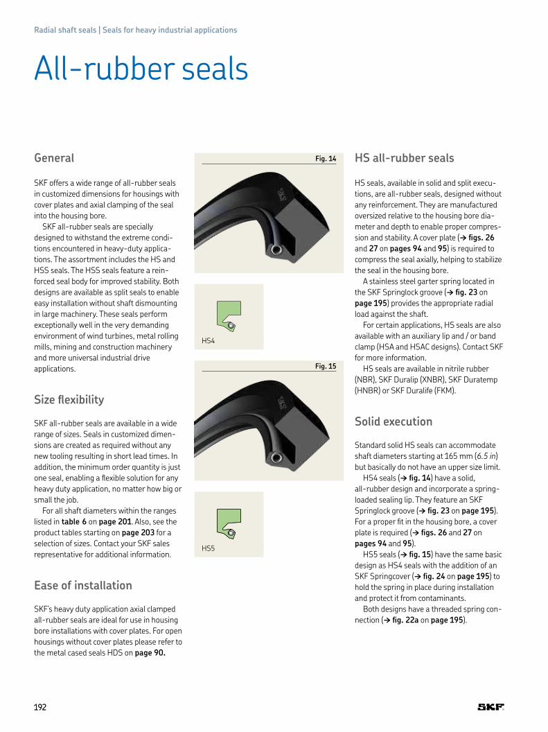
192192
Radial shaft seals | Seals for heavy industrial applications
HS all-rubber seals
HS seals, available in solid and split execu-
tions, are all-rubber seals, designed without
any re inforcement. They are manufactured
oversized relative to the housing bore dia-
meter and depth to enable proper compres-
sion and stability. A cover plate († igs. 26
and 27 on pages 94 and 95) is required to
compress the seal axially, helping to stabilize
the seal in the housing bore.
A stainless steel garter spring located in
the SKF Springlock groove († ig. 23 on
page 195) provides the appropriate radial
load against the shaft.
For certain applications, HS seals are also
available with an auxiliary lip and / or band
clamp (HSA and HSAC designs). Contact SKF
for more information.
HS seals are available in nitrile rubber
(NBR), SKF Duralip (XNBR), SKF Duratemp
(HNBR) or SKF Duralife (FKM).
Solid execution
Standard solid HS seals can accommodate
shaft diameters starting at 165 mm (6.5 in)
but basic ally do not have an upper size limit.
HS4 seals († ig. 14) have a solid,
all- rubber design and incorporate a spring-
loaded sealing lip. They feature an SKF
Springlock groove († ig. 23 on page 195).
For a proper it in the housing bore, a cover
plate is required († igs. 26 and 27 on
pages 94 and 95).
HS5 seals († ig. 15) have the same basic
design as HS4 seals with the addition of an
SKF Springcover († ig. 24 on page 195) to
hold the spring in place during installation
and protect it from contaminants.
Both designs have a threaded spring con-
nection († ig. 22a on page 195).
General
SKF offers a wide range of all-rubber seals
in customized dimensions for housings with
cover plates and axial clamping of the seal
into the housing bore.
SKF all-rubber seals are specially
designed to withstand the extreme condi-
tions encountered in heavy-duty applica-
tions. The assortment includes the HS and
HSS seals. The HSS seals feature a rein-
forced seal body for improved stability. Both
designs are available as split seals to enable
easy installation without shaft dismounting
in large machinery. These seals perform
exceptionally well in the very demanding
environment of wind turbines, metal rolling
mills, mining and construction machinery
and more universal industrial drive
applications.
Size lexibility
SKF all-rubber seals are available in a wide
range of sizes. Seals in customized dimen-
sions are created as required without any
new tooling resulting in short lead times. In
addition, the minimum order quantity is just
one seal, enabling a lexible solution for any
heavy duty application, no matter how big or
small the job.
For all shaft diameters within the ranges
listed in table 6 on page 201. Also, see the
product tables starting on page 203 for a
selection of sizes. Contact your SKF sales
represen tative for additional information.
Ease of installation
SKF’s heavy duty application axial clamped
all-rubber seals are ideal for use in housing
bore installations with cover plates. For open
housings without cover plates please refer to
the metal cased seals HDS on page 90.
Fig. 14
Fig. 15
HS4
HS5
All-rubber seals

193193
C
D
E
F
G
H
I
Sea
ls for
hea
vy in
dust
rial a
pplica
tions
A.2
Split execution
In applications where shaft removal is
impractical, HS all-rubber split seals are an
excellent choice. They are simply placed
around the shaft and pushed evenly into the
housing bore with the split at the 12 o’clock
position. A cover plate († igs. 27 and 28 on
pages 95) must be used to compress the
seal axially to stabilize it in the housing bore.
HS split seals perform best with grease or
high-viscosity lubricants. However, low-vis-
cosity lubricants are also suitable if the level
of lubricant is kept below the shaft centre
line, which is particularly important at con-
siderable surface speeds. Split seals are
preferably used on horizontal shafts, but can
also be used on vertical shafts in grease
lubricated applications.
HS6 seals († ig. 17) are designed with a
spring-loaded sealing lip and an SKF
Spring lock († ig. 23 on page 195). They
feature a separ ate loose spring and a hook-
and-eye spring connection for shaft diame-
ters above 455 mm (18 in) unless otherwise
speciied († ig. 22b on page 195). Smaller
sizes of HS6 seals come with a threaded
spring connection. For a proper it in the
Rubber outside diameter seals
HS6
Fig. 18
HS7 HS8
Cover plate installa- tion
Fig. 16
Installation
housing bore, a cover plate is required
(† igs. 26 and 27 on page 95).
HS7 seals († ig. 18), designed for
grease lubricated applications only, have a
wire controlled sealing lip and are designed
with both an SKF Springlock and SKF
Spring cover († igs. 23 and 24 on page
195). All HS7 seals feature a control-wire
spring connection († ig. 22c on page 195).
The spring is completely enclosed and the
connection is made by running the control
wire into the centre of the spring coil across
the split (butt joint). A built-in spring tension
holds the sealing lip on the shaft. For a
proper it, a cover plate is required († igs.
27 and 28 on pages 95). Due to the unique
design that enables easier installation, a gap
and minor leakage may occur at the joint
even after the cover plate is installed. It is
necessary to place the split at the 12 o'clock
position during installation († ig. 25 on
page 94). HS7 seals do not have the high
sealing characteristics of other HS seals, but
are the easiest to install.
HS8 seals († ig. 18) are designed with a
spring-loaded sealing lip, SKF Springlock,
SKF Springcover († igs. 23 and 24 on page
195) and a hook-and-eye spring con nection
(† ig. 22b on page 195) for shaft diam eters
above 455 mm (18 in). Smaller sizes of HS8
seals come with a threaded spring connec-
tion. The spring is entirely enclosed except
for a small portion on either side of the split.
HS8 seals provide the most effective sealing
performance of all split HS seals and are the
preferred design for retaining low-viscosity
lubricants and for water exclusion. HS8 seals
perform best on horizontal shafts, but can
also be used on ver tical shafts provided they
are not looded with lubricant.
More information on spring connections
for split seals can be found on page 195.
Fig. 17

194194
Radial shaft seals | Seals for heavy industrial applications
HSS reinforced all-rubber seals
HSS seals constitute a range of seals with a
variety of design following the same design
standard and designation system as the HS
assortment. Additional features are the
reinforced seal body and optional lubrication
grooves ig. 20 at the back of the seal to
allow re-greasing between the sealing lips
in back-to-back or tandem installations of
two HSS seals.
HSS4 and HSS5 are solid, HSS6 and
HSS8 are split seal executions. HSS5 and
HSS8 are featured with the SKF Springcover
(† ig. 24 on page 195). For seals with
lubrication grooves the designation includes
the sufix G (e.g. HSS5G).
HSS seals are available in nitrile rubber
(NBR), SKF Duratemp (HNBR) or SKF Dura-
life (FKM) for all shaft diameters within the
ranges listed in matrix 2 on page 180. Also
see the product tables starting on page
203. for a selection of sizes. Additional
please refer to the unsurpassed size
lexibility of HSS seals, customized dimen-
sions without any new tooling and minimum
order quantity of one seal only. Contact your
SKF sales representative for additional
information.
HSA7, HSA8, HSA7C, HSA8C
HSA7 and HSA8 are speciically designed for
the harsh conditions in the very slow rotat-
ing horizontal grinding mills in cement and
mining industries. The seals feature a
stronger shaft interference than HS7 and
HS8 seals for an improved lubricant reten-
tion at very low speeds and an additional
auxiliary dust lip to keep the heavy dust con-
tamination in the application out of the
bearing.
HSA7C and HSA8C seals are equipped
with an outer diameter retention ring to
simulate the outer diameter interference in
radially open housing bores († ig 21)
HSA7 seals († ig. 21) is designed for
grease lubricated applications only, have a
wire controlled sealing lip and are designed
with both an SKF Springlock and SKF
Springcover († igs. 23 and 24 on
page 195).
For a proper it, a cover plate is required
(igs. 26 and 27 on page 95). Due to the
unique design that enables easier installa-
tion, a gap and minor leakage may occur
at the joint even after the cover plate is
installed. It is necessary to place the split at
the 12 o’clock position during installation
(† ig. 24 on page 92).
HSA7 seals do not have the advanced
sealing characteristics of other HS seals,
but are the easiest to install.
HSA8 seals are designed with a spring-
loaded sealing lip, SKF Springlock, SKF
Springcover († igs. 23 and 24 on page
195) and a hook-and-eye spring connection
(† ig. 22b on page 195). The spring is
entirely enclosed except for a small portion
on either side of the split.
HSA8 seals provide the most effective
sealing performance and are the preferred
design for retaining low-viscosity lubricants.
HSS4 / HSS6
HSA7 / HSA8 HSA7C / HSA8C
Fig. 19
Fig. 20
Fig. 21
HSS5 / HSS8

195195
C
D
E
F
G
H
I
Sea
ls for
hea
vy in
dust
rial a
pplica
tions
A.2
Spring connections for split seals
There are different ways to connect the stainless steel garter springs
of HS and HSS split seals. A threaded spring connection († ig. 22a)
is used for all solid HS and HSS seals as well as the split HS6 / HSS6
and HS8 / HSS8 seals for shaft diameters ≤ 455 mm (18 in). A hook-
and-eye spring connection († ig.22b) is used for HS6 / HSS6 and
HS8 / HSS8 seals for shaft diameters > 455 mm (18 in). HS7 seals
feature the special control-wire connection († ig.22c), are only to
be used for grease applications when the other spring connections
cannot be installed.
SKF Springlock
The SKF Springlock is a sealing lip feature that surrounds 270° of the
garter spring diameter († ig. 23). It helps holding the spring in posi-
tion during installation and is standard on all HS and HSS seals.
SKF Springcover
For blind installations, where spring displacement may go unde-
tected, the SKF Springcover († ig. 24) can be speciied. It also pro-
tects the spring from dirt, water and other contaminants. SKF
Springcover is lexible and covers the exposed portion of the stainless
steel garter spring without adversely affecting the spring’s capability.
Fig. 23
Fig. 24
Additional design features for HS and HSS seals
a
b
c
Fig. 22
Spring connections
Reinforced all-rubber HSS seals , Additional design features for HS and HSS seals

196196
Radial shaft seals | Seals for heavy industrial applications
Fig. 25
Fig. 26
HRS seals
General
HRS seals from SKF were specially designed
to cope with the harsh conditions that wind
turbine main shafts face. They offer lubricant
retention and contamination exclusion to
reduce the risks of lubrication or contami-
nant-related bearings failures and their con-
sequences, such as production downtime
and repair costs. These high performance
radial shaft seals can deliver signiicantly
extended service life and help operators to
reduce maintenance costs and ultimately
increase reliability. These seals can also be
used for other heavy duty applications.
Beneits and features
• Extended service life due to high abrasion
resistance
• Reduced bearing failures related to
contamination
• Resistance against hydrolysis, UV radiation
and ozone due to H-ECOPUR and
G-ECOPUR material
• Increased reliability
• Facilitated up-tower retroits
• Reduced OPEX during machine life
• Easy installation
• Customization of seal size thanks to
lexible manufacturing process
Easy up-tower usage
The split seals are single packed
and designed to fulill the needs in the
wind aftermarket. Each package con-
tains a seal with the garter spring and
an installation guide. To allow for easy
handling and transportation for large
diameter seals, these seals are folded.
For more information on installing a
split seal, please see page 91.
!
HRS1
HRSA

197197
C
D
E
F
G
H
I
Sea
ls for
hea
vy in
dust
rial a
pplica
tions
A.2
HRS seals
HRS and HRSA radial shaft seals
These large diameter radial shaft seals
(† igs. 25 and 26), are designed to protect
large size bearings in grease lubrication and
low pressure differentials. A lexible manu-
facturing process allows a degree of custom-
ization to the seal dimensions to help meet
unusual requirements.
HRSA seals († ig. 26) feature an addi-
tional auxiliary lip to protect the seal and the
application against contamination from the
environment.
HRS and HRSA seals feature a garter
spring that stabilizes the sealing lip,
increases the lip followability (DRO and
STBM) and maintains the sealing function
even in alternating operating temperatures.
The seals are designed to secure the garter
spring inside the spring groove once the
seals are installed.
Solid seals feature an endless garter
spring, while split seals feature an open con-
nection that is closed during seal installation.
Fig. 27
HRS seals
Housing
HRS seal
Counterface
Cover plate (axial clamping)

198198
Radial shaft seals | Seals for heavy industrial applications
Fig. 28
HRE
Fig. 29
Housing
Counterface
Cover plate (axial clamping)
HRE seal
HRE radial excluder seal
HRE is a radial contacting excluder seal (†
ig. 28), designed to be used in combination
with HS, HSS or HRS radial shaft seals as
additional protection against contamination.
A lexible manufacturing process allows a
degree of customization to the seal dimen-
sions to help meet unusual requirements.
HRE seals are additional auxiliary lips for
contamination protection to be used in com-
bination with HS, HSS and HRS seals. They
are generally used where additional protec-
tion from contaminants is needed.
To avoid sealing lip with housing interfer-
ence please see the dimensional housing
requirements on page 91.

199199
C
D
E
F
G
H
I
Sea
ls for
hea
vy in
dust
rial a
pplica
tions
A.2
HRS seals
Material and manufacturing
ECOPUR is a thermoplastic polyurethane
(TPU) and has outstanding mechanical
properties like abrasion resistance against
contaminants.
G-ECOPUR and H-ECOPUR are hydroly-
sis-resistant polyurethanes with similar
properties.
The size of the seal will dictate whether
G-ECOPUR or H-ECOPUR is used.
G-ECOPUR
Standard seals are made of G-ECOPUR,
which is a casted polyurethane elastomer.
This material has outstanding wear
resistance and increased stiffness compared
to rubber materials († diagram 1).
Increased stiffness allows for easier han-
dling and minimizes the risk of installation
failures like bending the sealing lip or losing
the garter spring.
CNC manufacturing process
Featuring proprietary software and
high-precision cutting tools, the SKF SEAL
JET manufacturing system uses Computer
Numerical Control (CNC) technology to
machine polymeric seals quickly († page
56). The system machines a seal from a
semi-inished tube of the selected material.
Diagram 1
Abrasion wear of various sealing materials
G-ECOPUR
160
140
120
100
80
60
40
20
0
NBR FKM HNBR
Abrasion [mm3]
G-ECOPUR is 5 times more abrasion-resistant than the next best performing elastomer material.

200200
Radial shaft seals | Seals for heavy industrial applications
All SKF metal-cased HDS seals, HS seals,
HSS and HRS seals are made upon order in
any inch or metric size within the ranges
listed in tables 5, 6 and 7. New seal sizes are
manufactured without additional tooling and
can be supplied without extended lead
times. The product tables starting on page
203, list a selection of sizes. For any size that
is not listed in the product tables, contact
your SKF distributor or SKF sales
representative.
Table 5
Standard sizes for metal-cased HDS seal designs
Designs with metal Shaft diameter d1 Bore diameter D Nominal seal width B Difference between
outside diameter bore and shaft diameter
from to from to from to from to
– mm/in mm/in mm/in mm/in
HDS7 114,30 1 608,30 139,70 1 638,30 12,70 31,75 25,40 76,20
4.500 63.319 5.500 64.500 0.500 1.250 1.000 3.000
HDSH7 114,30 1 608,30 139,70 1 638,30 15,00 31,75 25,40 50,80
6.500 63.250 7.750 64.500 0.787 1.250 1.250 2.500
HDS1–2, HDSF1–2 114,30 1 608,30 127,00 1 638,30 12,70 31,75 25,40 76,20
4.500 63.319 7.750 64.500 0.625 1.250 1.250 3.000
HDSH1–2 114,30 1 608,30 127,00 1 638,30 17,07 31,75 25,40 76,20
4.500 63.319 5.000 64.500 0.627 1.250 1.000 3.000
HDSA1–2 114,30 1 189,20 139,70 1 219,20 17,48 38,10 25,40 76,20
4.500 46.819 5.500 48.000 0.688 1.500 1.000 3.000
HDSD2, HDSE2 114,30 1 602,97 143,51 1 638,30 28,58 57,15 29,21 76,204.500 63.109 5.650 64.500 1.125 2.250 1.150 3.000
HDSEH1–2 165,10 1 603,50 202,18 1 638,30 39,98 50,80 37,08 76,20
6.500 63.130 7.960 64.500 1.574 2.000 1.460 3.000
Not all cross sections and widths are possible with every shaft diameter. Contact SKF for information on dimensions at the extreme limits or for sizes outside the standard range.
Size options of heavy industrial seals
114,3–
1 608,3 mm
D 127–
1 638,3 mm
25,40–76,2 mm
B 12,7–57,15 mm
d1
Note: Not all combinations are possible
Fig. 30
HDS nominal housing dimensions

201201
C
D
E
F
G
H
I
Sea
ls for
hea
vy in
dust
rial a
pplica
tions
A.2
Size options of heavy industrial seals
Not all cross sections and widths are possible with every shaft diameter. Contact SKF for information on dimensions at the extreme limits or for sizes outside the standard range.
4 572 mm
D 125–
4 695,95 mm
25–123,95 mm
B 11,13–26,92 mm
d1 100–
Note: Not all combinations are possible
Fig. 31
HS and HSS nominal housing dimensions
d1 350–
3 900 mm
D 390–
3 960 mm
20–… mm
B 20–… mm
Note: Not all combinations are possible
Fig. 32
HRS nominal housing dimensions
Table 6
Standard size for all rubber and polyurethane seals
Designs with metal Shaft diameter d1 Bore diameter D Nominal seal width B Difference between
outside diameter bore and shaft diameter
from to from to from to from to
– mm/in mm/in mm/in mm/in
HS 100 4 572 125 4 636 11,13 25,4 25 64
3,937 180 4,921 182,52 0,438 1 0,984 2,52
HSS 203,2 4 572 233,2 4 636 12,7 25,4 30 64
8 180 9,181 182,52 0,5 1 1,181 2,52
HSA7 / HSA8 711,2 4 572 753,11 4 695,95 22,86 26,92 41,91 123,95
28 180 29,65 184,88 0,9 1,06 1,65 4,88
HRS 350 3 900 390 3 960 20 – 20 –
13,78 153,543 15,354 155,906 0,787 – 0,787 –
HRE 350 3 900 390 3 960 5 – 20 –
13,78 153,543 15,354 155,906 0,197 – 0,787 –

Table 7
Standard size options for HRS seals
Shaft diameter d1 Bore diameter D Bore depth B Difference between bore and shaft diameter
from to from to HRS, HRSA HRS, HRE min. min. recommended
mm/in mm/in mm/in mm/in
350 3 900 390 3 960 ≥ 20 ≥ 25 ≥ 20 ≥ 25
13.780 153.543 15.354 155.906 0.787 0.984 0.787 0.984
1) Tolerance h112) Tolerance H83) Tolerance ±0,13 mm (0.005 in)Not all cross sections and widths are possible with every shaft diameter. Contact SKF for information on dimensions at the extreme limits or on sizes outside the standard range.
202202
Radial shaft seals | Seals for heavy industrial applications

Product tables
203203
I
Sea
ls for
hea
vy in
dust
rial a
pplica
tions
A.2
Please use size tables in section Size options of heavy industrial seals on page 200 to determine your required seal type and size.
Radial shaft seals | Seals for heavy industrial applications – metric dimensions
d1 100–190 mm
Principal dimensions
d1 D B
d1 D B
d1 D B
d1 D B
100 130 12,5105 130 12105 130 13105 135 12105 135 13105 140 12105 143 16105 145 16107 147 16110 135 12,5110 140 12110 140 13110 140 15110 140 16110 142 12110 143 18110 145 19110 150 16110 150,1 16110 152 15113 140 13114 139 15114 140 13,3115 140 12115 140 13115 145 15115 150 12115 150 15115 155 16118 150 15120 140 12120 145 15,5120 150 12120 150 13120 150 14120 150 15120 150 16120 152 16120 155 18120 160 12120 160 15120 160 16120 160 18120 170 16125 150 12125 150 13125 151 17125 155 12125 155 12,5
125 155 14125 157 12,5125 160 12125 160 15125 165 15125 165 15,8125 165 16125 170 13126 160 15127 165 16130 155 12,5130 155 15,5130 160 12130 160 15130 160 18130 165 13130 165 18130 170 12130 170 16133 165 12,5135 160 12135 161 13135 165 12135 167 15135 170 12135 170 15135 170 16,5135 175 16140 165 12140 168 21140 170 12140 170 14140 170 15140 170 16140 175 15140 178 16140 180 15140 180 16140 180 17145 170 13145 174 14145 175 14145 175 15145 180 12145 180 13145 180 14145 180 15145 180 18145 180 20
145 185 16145 185 18146 178 16149 178 13149 180 13150 180 12150 180 13150 180 14150 180 15150 180 16150 182 16150 185 18150 186 20150 190 15150 190 16150 195 16151 183 13152 181 12,5152 191 13152,5 183 15155 180 12,5155 180 13155 190 13155 190 15155 195 16155 195 18156 185 13156 200 16160 185 12,5160 188 21160 190 14,3160 190 15160 190 16160 190 16,5160 190 20160 196 20160 200 15160 200 15,9160 200 16160 200 17160 211 16162 190 12162 202 16165 190 13165 190 15165 195 15165 200 15165 205 16166 206 16
170 195 13170 200 12170 200 15170 200 16170 205 16170 210 16170 210 20170 211 16170 220 15175 200 15175 205 15175 213 19175 215 15175 215 16178 210 14179 219 16180 205 12180 205 13180 210 12180 210 14180 210 15180 210 16180 210 20180 215 15180 215 16180 215 18180 215 19180 220 15180 220 16180 220 20180 222 16181 219 15182 215 16185 215 15185 220 12,7185 225 16185 225 16,5186 226 16188 215 16189 215 16190 215 16190 220 13190 220 15190 220 16190 225 15190 225 16190 225 18190 230 15190 230 16
B
d1 D
In all listed sizes seals can be conigured to
application requirements. Not all combinations
of sizes and designs are possible, please refer
to tables for seal design selection pages 176 to
183 and size capabilities page 201 to 202 or
contact your SKF representative.

204204
Radial shaft seals | Seals for heavy industrial applications – metric dimensions
d1 190–285 mm
Please use size tables in section Size options of heavy industrial seals on page 200 to determine your required seal type and size
Principal dimensions
d1 D B
d1 D B
d1 D B
d1 D B
190 230 17190 230,1 16190 234 20190 235 16190 240 20195 220 12,7195 220,4 17,7195 235 16195 250 22197 236 16200 225 15200 230 14200 230 15200 230 16200 230,1 15200 235 15200 235 16200 235 18200 235 19200 235 20200 238 19200 238,1 18200 238,1 19,1200 240 15200 240 16200 240 17,5200 240 18200 240 20200 250 15200 250 18200 255 22203 241 16205 230 15205 245 16205 245 20205 250 16208 233 12,5210 235 13210 235 15,8210 240 12210 240 14210 240 15210 240 16210 240 18210 240 20210 245 16210 245 16,5210 245 18210 245 18,2210 250 15210 250 16210 250 18210 250 20210 260 15210 265 23210 270 15210 270 16215 240 12215 240 20215 245 16215 248 15215 250 16215 255 16215 265 21,5215 270 23216 254 16218,4 250 15219 250 12220 250 12220 250 15220 250 16220 250 16,5220 250 18220 250 20
220 250 22220 255 16220 255 18220 255 18,3220 260 14,3220 260 15220 260 16220 260 16,5220 260 18220 260 19220 260 20220 260 22220 275 23224 260 16224 274 20225 250 15225 250 16225 255 15225 257 16225 260 20225 260 22225 265 16225 265 20225 290 16226 258 16226 270 16226 276 22,3228 268 16228 268 20229 267 19229 270 17230 260 15230 260 15,7230 260 16230 260 18230 260 20230 262 15230 264 16230 265 16230 265 18230 265 20230 269 22230 270 16230 270 18230 270 20230 280 16230 280 20230 285 23230 320 18235 265 15235 265 15,3235 267 15235 270 15235 270 16235 273 19235 275 16235 275 20236 276 16238 270 16238 290 25240 265 13240 270 12,7240 270 13,5240 270 15240 270 16240 270 17240 270 18240 275 15240 275 16240 275 18240 275,1 18240 279 22240 279,9 16240 280 14
240 280 16240 280 18240 280 19240 280 20240 280 22240 280 23240 290 16240 290 20240 290 25240 300 25241 279 19244 284 16245 275 16245 285 16245 288 16245 290 15248 298 19250 280 15250 280 16250 280 20250 280 22250 285 15250 285 16250 285 17250 285 18250 290 15250 290 16250 290 16,5250 290 18250 290 20250 294 20250 295 24250 300 20250 310 25254 290 15254 305 21255 290 16255 290,1 16255 295 16255 299 20255 315 25256 300 20258 290 16260 285 12,7260 285 13260 285,4 12,7260 290 16260 290 19260 290 20260 295 17260 298 17260 300 14260 300 14,4260 300 15260 300 16260 300 18260 300 20260 300 22260 304 20260 305 16260 305 22260 310 16260 315 24260 320 25261 311 16264 310 13264 310 17264,8 300 20264,8 304 20265 295 15265 300 15265 300 16265 303 15265 303 16
265 305 18265 309 20265 310 16265 310 22266 310 20267 308 19267 308 20267 308 22267 315 15270 260 15270 300 15270 310 15270 310 16270 310 18270 310 20270 310 20,5270 310,3 16270 314 19270 314 20270 314 26270 320 16270 330 18270 330 25270 335 18272 304 15,8272 304 16273 311 15273 317 19275 307 13275 310 15275 310 16275 315 18275 315 20275 319 18275 319 20275 320 15275 320 16278 312 16279 310 16279 323 20280 310 14280 310 15280 310 16280 310 20280 315 15280 318 15280 318,7 27280 320 16280 320 17280 320 18280 320 19280 320 19,1280 320 19,6280 320 20280 320 22280 322 20280 324 20280 325 20280 325 22280 325 24280 330 20280 330 20,6280 330 24280 340 15280 340 20280 340 25280 350 16285 310 13285 310 16285 320 16285 320 20285 324 20285 325 16285 325 18

205205
Seals for heavy industrial applications – metric dimensions
d1 285–380 mm
I
Sea
ls for
hea
vy in
dust
rial a
pplica
tions
A.2
Please use size tables in section Size options of heavy industrial seals on page 200 to determine your required seal type and size
Principal dimensions
d1 D B
d1 D B
d1 D B
d1 D B
285 325 20285 329 20286 336,6 15289 327 19290 320 15290 320 16290 320 18290 329,7 16290 330 16290 330 18290 330 20290 330 20,3290 334 20290 334 20,3290 334 20,5290 335 24290 340 20290 350 15290 350 25292 336 20292 350 16295 325 15295 330 16295 330 17,5295 330 18295 335 16295 335 18295 339 20295 344 20296 340 20298 338 16298 340 17300 325,4 12,7300 330 14300 330 15300 332 16300 335 15300 335 18300 340 16300 340 16,5300 340 18300 340 20300 340 22300 340 22,2300 344 16300 344 20300 344 22300 345 22300 345 25300 350 24300 350 25300 360 20300 360 25300 390 20300 390 25302 342 16304 348 20305 345 20305 349 20305 355 22,5308 352 20310 310 16310 340 15310 340 20310 345 18310 350 16310 350 18310 350 20310 353 20310 354 19,3310 354 20310 354 20,5310 355 20310 355 24
310 355,6 20310 360 22310 370 25311 345 18311 345 18,3314 355 20315 345 14315 345 20315 347 13315 355 16315 355 18315 355 20315 359 22315 360 20315 364 20315 365 20316 360 20317 352 16317 352 23317 361 20318 348 19318 360 20320 350 15320 350 15,4320 350 16320 350 18320 350 20320 355 16320 358 19320 358 20320 360 12320 360 15320 360 16320 360 18320 360 20320 360 22320 360 22,2320 360 25320 364 20320 368,1 19320 370 25320 380 25323 363 16324 362 17,5324 365 22325 360 20325 363 16325 365 16325 365 18325 365 20325 368 20325 369 19,3325 369 20325 370 20325 375 22,8325 375 25328 372 20,2330 360 14330 360 18330 365 14330 370 14330 370 15330 370 16330 370 18330 370 20330 370 21330 370 25330 374 17330 374 18330 374 19330 374 20330 380 19330 380 20330 380 22
330 384 18330 390 18330 390 20330 390 25331 371 14331 371 15331 371 16335 365 16335 373 19335 375 15335 375 18335 379 20335 380 20335 395 16336 380 20340 370 16340 370 18340 372 16340 372 18340 372 20340 380 15340 380 16340 380 18340 380 20340 380 22340 384 20340 385 20340 390 25340 400 25342 380 16343 381 21345 384 20345 389 20345 390 25345 395 20346 375 15348 380 16349 395 18350 380 15350 380 16350 380 17,7350 380 20350 380 20,5350 382 20350 390 5350 390 16350 390 18350 390 20350 391 16350 394 5350 394 20350 394 20,1350 394 21350 394 22350 400 5350 400 17350 400 25350,6 395 5351 390 20351 391 16351 407 24355 393 18355 393 20355 394 20355 395 5355 395 20355 399 5355 399 20355 405 5355 405 20356 400 5356 400 16356 400 20356 432 5
356 432 28360 390 15,9360 390 18360 392 15,9360 392 20360 398 19360 398 20360 400 5360 400 17360 400 18360 400 20360 400 22360 400 23360 400 25360 404 5360 404 16360 404 17,5360 404 20360 405 25360 410 5360 410 20360 410,8 22,3360 411 22,3360 420 15360 420 25362 400 16362 400 20362 402 18362 406 5362 406 19,5362 406 19,8362 406 20362 406 22362 412 25363 418 5363 418 20364 406 17364 420 25364,5 400 20365 400 17365 405 5365 405 18365 405 20365 409 5365 409 20366 410 5367 405 18370 410 5370 410 15370 410 16370 410 18370 410 20370 414 5370 414 13370 414 16370 414 19370 414 20370 420 5370 420 15370 420 20370 420 25375 419 5375 419 20375 420 16375 420 18375 435 25376 427 5380 412 16380 418 19380 419 24380 419 25380 420 5380 420 15380 420 16

206206
Radial shaft seals | Seals for heavy industrial applications – metric dimensions
d1 380–490 mm
Please use size tables in section Size options of heavy industrial seals on page 200 to determine your required seal type and size
Principal dimensions
d1 D B
d1 D B
d1 D B
d1 D B
380 420 18380 420 19380 420 20380 420 22380 420 22,2380 420 25380 423,9 5380 424 5380 424 20380 425 20380 429 5380 429 24380 430 19380 430 20380 430,8 5380 435 5380 435 25380 440 5380 440 16380 440 23380 440 25384 414 15385 421 16385 425 18385 425 18,3385 429 5385 429 20385 432 15385 435 5385 435 22385 435 25387 431 5387 431 22387 431 22,5387 438 5387,4 431 5388 418 15390 420 14390 420 16390 420 20390 424,8 13,5390 430 5390 430 16390 430 18390 430 19390 430 20390 434 5390 434 18390 434 20390 434 22390 435 25390 450 25392 432 18395 430 16395 430 18395 430 20395 439 5395 439 19395 439 20395 439 20,5399 431 19400 430 20400 440 5400 440 14400 440 18400 440 20400 440 22400 444 5400 444 13,5400 444 20400 444 22400 444,5 22400 447 20400 450 5
400 450 17,5400 450 18400 450 18,1400 450 20400 450 22400 450 22,5400 450 25400 451 5400 451 22,2400 460 5400 460 25405 449 5405 449 20405 455 5405 455 22405 455,6 5410 350 18410 440 16410 450 5410 450 17,5410 450 18410 450 20410 454 5410 454 19410 454 20410 460 5410 460 22410 460 25410 470 16410 470 25413 463 5413 463 22415 465 5415 465 20415 465 22415 465 25416 466 5416 466 21,5418 455 16419 451 19420 460 5420 460 15420 460 17420 460 18420 460 20420 460 22,2420 464 5420 464 20420 470 5420 470 20420 470 22420 470 23420 470 25420 480 5420 480 24420 480 25425 465 20425 475 5425 475 25425 480 22425 483 5425 483 23430 460 15430 468 22430 470 20430 474 5430 474 20430 480 5430 480 16430 480 18430 480 20430 480 21,5430 480 22430 480 25
430 480 27,5430 480 30430 490 25431 488 19432 463 17432 470 21,5432 470 22435 475 20435 485 5435 485 18435 485 22435 485 22,6435 485 23438 476 24440 470 20440 472 16440 472 20440 480 5440 480 20440 480 21440 480 22,2440 480 26440 484 20440 484,3 19440 490 5440 490 20440 490 20,5440 490 22440 490 25440 490 28442 472 20445 485 18445 485 20445 495 5445 495 22446 486 16446 486 16,5446 496 22448 480 16449 500 5449 500 23450 480 17,5450 480 20450 490 18450 490 20450 490 22450 494 5450 494 20450 500 5450 500 18450 500 20450 500 22450 500 22,4450 500 23450 500 24450 500 25450 510 25452 496 15452 503 20,7454 500 18454 504 5454 504 21455 505 5455 505 21,8455 505 22455 505 25457 508 5458 494 18458 505 20,6460 500 5460 500 16460 500 18460 500 20460 500 22
460 500 23460 504 20460 510 5460 510 20460 510 20,6460 510 21460 510 21,5460 510 22460 510 25460 520 20460 520 25461 495 20461,5 540 5461,5 540 31463 528 20465 495 20465 510 20465 510 22465 520 22467 510 5467 510 20467 510 25467,1 510 5468 530 20470 508 19470 510 5470 510 18470 510 20470 510 22470 520 5470 520 20470 520 20,7470 520 22470 520 24470 520 25470 530 5470 530 20470 530 25470 530 30474 514 5474 514 20475 505 17475 525 5475 525 22475 525 25475 525,8 5475 530 18475,8 520 5475,8 520 22480 450 20480 514 15480 520 5480 520 18480 520 20480 520 22480 524 5480 524 20480 530 5480 530 18480 530 20480 530 22480 530 25480 540 20480 540 25480 550 5480 550 25485 530 20485 535 5485 535 19485 535 20485 535 22490 530 5490 530 20490 530 20,5

207207
Seals for heavy industrial applications – metric dimensions
d1 490–630 mm
I
Sea
ls for
hea
vy in
dust
rial a
pplica
tions
A.2
Please use size tables in section Size options of heavy industrial seals on page 200 to determine your required seal type and size
Principal dimensions
d1 D B
d1 D B
d1 D B
d1 D B
490 540 5490 540 22490 540 25490 541 21493 543 5493 543 26495 545 5495 545 22495 560 25495,5 546 5495,5 546 22497 540 5497 540 20500 540 5500 540 16500 540 20500 540 22500 544 5500 544 20500 544 22500 544,5 5500 545 5500 545 20500 545 20,5500 550 5500 550 18500 550 19500 550 20500 550 22500 550 24,5500 550 25500 550,8 5500 558,8 5500 558,8 22500 560 5500 560 18500 560 25500 564 5500 564 25502 542 5502 542 20503 552 5503 552 20503 553 5503 553 22505 535 15505 555 20,6508 558,8 5508 559 19508 560 25508 565 22,5510 520 20510 548 24510 548 25510 550 5510 550 17,5510 550 20510 554 5510 554 19,5510 554 20510 560 5510 560 22510 560 22,5510 560 25511 561 22513 543 16515 555 5515 555 20515 565 5515 565 22515 565 25519 560 21519 560 25520 560 5
520 560 18520 560 20520 564 5520 564 20520 570 5520 570 18520 570 22520 570 22,6520 570 24520 570 25520 580 20520 580 25524 574 25525 555 18525 569 5525 569 20525 575 5525 575 20525 575 22525 575 25528 578 5528 578 22530 570 20530 570 22530 574 20530 575 20530 576 21530 580 5530 580 20530 580 20,6530 580 22530 580 22,3530 580 24,2530 580 24,5530 580 25530 580,8 5530 580,8 21530 590 5530 590 38530 620 5530 620 22534 584 5534 584 22535 580 20535 585 5535 585 22535 585 27538 570 20538 590 20540 570 20540 580 20540 584 5540 584 20540 585 18540 590 5540 590 18540 590 20540 590 22540 590 22,6540 590 25540 590 27,5540 590 30540 600 20542 578 16542 578 18545 595 5545 595 22548 610 25549 600,8 5549,3 600,1 5550 590 5550 590 20550 600 5550 600 19
550 600 20550 600 22550 600 22,3550 600 23,5550 600 25550 610 5550 610 25550 620 25550 660 23,5555 605 5555 605 22556 610 25559 597 19560 590 20560 600 5560 600 18560 600 20560 603 5560 603 20560 604 5560 604 16560 604 20560 610 5560 610 20560 610 22560 610 22,3560 610 25560 610 26560 620 25565 601 20565 615 5565 615 22565,2 616 5569,9 619,1 5570 604 15570 610 18570 610 20570 616 19570 620 5570 620 20570 620 22570 620 25574 610 16575 619 5575 619 20575 625 5575 625 22580 550 20580 610 20580 615 20580 616 16580 616 17580 620 5580 620 20580 620 25580 630 5580 630 18580 630 22580 630 25580 640 16580 640 25580 650 25585 620 20585 635 5585 635 22586 646 5586 646 22586 650 25587 637 5587 637 22588 638 5588 638 23590 630 20590 630 22
590 640 5590 640 20590 640 22590 640 22,8590 640 25600 640 5600 640 18600 640 20600 640 25600 649,2 5600 650 5600 650 18600 650 22600 650 25600 660 5600 660 18600 660 25600 660 30600 664 5600 664 25604 640 22605 640 20605 645 18605 655 5605 655 20605 655 22610 620 20610 650 20610 650 22,5610 650 25610 654 20610 660 5610 660 20610 660 22610 660 25610 674 5610 674 22610 674 25614 658 5614 658 20615 645 20615 665 5615 665 20,5615 665 24615 665 24,5616 666,8 5616 666,8 22616 679,8 5616 679,8 25616 680 5616 680 25620 660 20620 670 5620 670 20620 670 22620 680 20620 684 5620 684 25625 655 20625 665 25625 670 5625 670 20625 675 25625 675,8 19625 676 19625 689 5625 689 25630 660 15630 660 25630 670 20630 674 20630 680 5630 680 22630 680 25

208208
Radial shaft seals | Seals for heavy industrial applications – metric dimensions
d1 630–800 mm
Please use size tables in section Size options of heavy industrial seals on page 200 to determine your required seal type and size
Principal dimensions
d1 D B
d1 D B
d1 D B
d1 D B
630 690 5630 690 20630 690 25630 690 30630 694 5630 694 25635 685 5635 685 22635 699 5635 699 25635 705 5635 705 30636 692 5636 692 30,5638 678 20640 680 5640 680 20640 680 25640 684 5640 684 20640 688 5640 688 20640 690 5640 690 22640 690 25640 700 25640 704 5640 704 25641 707 5641 707 25645 695 5645 695 22645 700 22647 700 25648 690 20650 680 15650 686 20650 690 5650 690 18650 690 20650 690 22650 690 25650 700 5650 700 20650 700 22650 700 25650 710 25650 714 5650 714 25655 690 20658 703 25658 716 25660 650 20660 690 18660 700 5660 700 15660 700 18660 700 20660 700 25660 704 5660 704 18660 704 20660 710 5660 710 22660 710 25660 716 25660 720 22660 724 5660 724 25664 715 25665 715 5665 715 22665 729 5665 729 25
668 706 25670 704 15670 710 5670 710 18670 710 20670 714 5670 714 20670 714 22670 720 24670 720 25670 730 25670 734 5670 734 22670 734 25672 737 5672 737 25676 740 5676 740 22676 740 25676 740 28679,5 743 5679,5 743 25680 700 20680 720 5680 720 20680 730 5680 730 20680 730 22680 730 25680 744 5680 744 25680 780 5680 780 20685 720 20685 735 5685 735 22685 737 5685 737 22685 749 5685 749 25686 740 5686 740 25690 730 20690 734 20690 740 5690 740 22690 740 25690 754 5690 754 25692 732 15700 740 20700 750 5700 750 20700 750 25700 760 5700 760 25700 760 30700 764 5700 764 20700 764 25700 765 25710 750 20710 750 23710 760 5710 760 20710 760 22710 760 22,2710 760 24,9710 760 25710 770 5710 770 25710 770 30710 774 5710 774 22
710 774 25710 774 30711 775 5711 775 25712 757 20,5715 779 25716 780 5716 780 25720 760 18720 770 25720 771,1 21720 780 5720 780 25720 784 5720 784 23720 784 25724 775 5724 775 22725 775 25725 789,2 25730 770 5730 770 20730 780 5730 780 20730 780 22730 780 25730 790 25730 794 5730 794 25735 795 25735 799 5735 799 25736 800 5736 800 25737 790 16740 780 5740 780 16,5740 780 18740 780 25740 782 18740 785 18740 790 16740 790 20740 790 25740 804 5740 804 25744 808 5744 808 25744 808 30748 812 5748 812 25750 780 18750 790 5750 790 20750 790 23750 800 5750 800 22750 800 25750 800 27,5750 800 28750 810 5750 810 22750 810 25750 810 30750 810 36750 814 5750 814 25750 814 28750 840 5750 840 25750,1 810 5760 800 5760 800 20760 800 20,6
760 804 5760 804 20760 810 20,6760 810 25760 813 22760 820 5760 820 18760 820 25760 820 30760 824 22760 824 25760 830 5760 830 30762 791 13762 812,8 5762 825,5 5770 810 20770 834 5770 834 20770 834 25775 825 5775 825 25775 839 5775 839 25775 839 31776 820 5776 820 20778 818 20,5780 820 18780 820 19780 820 20780 830 5780 830 22780 830 25780 830 27,5780 844 5780 844 20780 844 25786 836 5786 836 25790 830 5790 830 23790 834 5790 834 25790 840 5790 840 20790 840 22790 840 25790 845 5790 845 25790 850 5790 850 25790 850 30790 854 5790 854 25799 860 5799 860 26800 840 5800 840 16800 840 18800 840 20800 840 25800 850 20800 850 25800 860 5800 860 16800 860 25800 860 30800 864 5800 864 23800 864 25800 865 5800 865 25800 870 5

209209
Seals for heavy industrial applications – metric dimensions
d1 800–1 140 mm
I
Sea
ls for
hea
vy in
dust
rial a
pplica
tions
A.2
Please use size tables in section Size options of heavy industrial seals on page 200 to determine your required seal type and size
Principal dimensions
d1 D B
d1 D B
d1 D B
d1 D B
800 870 25800 870 30800 874 5800 874 25805 869 5805 869 25810 850 17810 850 20810 854 5810 854 20810 860 5810 860 21810 860 25810 870 5810 870 25810 874 5810 874 22810 874 23810 874 25815 865 5815 865 25816 866,8 5820 860 16820 860 18820 860 20820 870 5820 870 22820 870 25820 884 5820 884 25820 884 28825 860 20825 875 5825 875 22825 875 25825,5 877 20826 876 5826 876 30830 874 20830 890 5830 890 23830 894 5830 894 22830 894 25835 899 5835 899 25836 896 5836 896 30837 889 22,2838 880 5838 880 20840 880 18840 880 23840 890 25840 892 18840 900 25840 904 5840 904 25840 910 25850 890 5850 890 20850 900 5850 900 19850 900 20850 900 22850 904 5850 904 25850 910 5850 910 22850 910 25850 910 30850 914 5850 914 25850 924 5
850 924 25850 925 25853 917 20853 917 22,1853 917 25860 900 20860 920 5860 920 22860 920 25860 924 5860 924 16860 924 25860 950 5860 950 32864 928 5864 928 25865 911 18867 920 16870 910 20870 920 5870 920 16870 920 20870 920 25870 930 25870 934 5870 934 24870 934 25870 935 23880 940 5880 940 25880 940 30880 944 5880 944 22880 944 25880 944 25,6885 919 15890 930 18890 930 20890 930 23890 940 5890 940 25890 954 5890 954 22890 954 25893 925 20900 940 5900 940 20900 950 25900 960 5900 960 25900 960 27900 960 30900 964 5900 964 25900 964 32900 980 5900 980 23910 950 25910 960 5910 960 25910 966 17,9910 966 18910 967 17,9910 974 5910 974 22910 974 25920 958 19920 970 5920 970 20920 970 25920 980 5920 980 25920 980 30920 984 5
920 984 25925 975 22927 978 22930 980 5930 980 20930 980 22,2930 980 25930 990 5930 990 25930 994 5930 994 25930 1 000 5930 1 000 30934 984 5934 984 22934 984 25939 971 22,2940 995 5940 995 25940 1 000 25940 1 004 5940 1 004 25950 980 18950 990 18950 990 20950 1 000 5950 1 000 25950 1 006 20950 1 010 5950 1 010 25950 1 010 30950 1 014 5950 1 014 25953 1 003 5953 1 003 22953 1 003 25954 1 004 5954 1 004 22954 1 004 25955 1 019 5955 1 019 25960 1 000 20960 1 000 25960 1 020 25960 1 024 5960 1 024 25960 1 040 23965 1 015 5965 1 015 22965 1 015 25970 1 020 5970 1 020 22970 1 020 25970 1 030 5970 1 030 21,5970 1 030 22970 1 030 25970 1 034 5970 1 034 25975 1 034 25978 1 018 18980 1 030 5980 1 030 30985 1 045 5985 1 045 25990 1 030 20990 1 040 5990 1 040 22990 1 040 25990 1 045 25990 1 054 5990 1 054 25992 1 037 25995 1 025 15
1 000 1 035 201 000 1 050 201 000 1 050 231 000 1 050 251 000 1 060 51 000 1 060 201 000 1 060 251 000 1 060 301 000 1 064 51 000 1 064 251 020 1 070 201 020 1 070 251 020 1 080 51 020 1 080 20,51 020 1 080 251 020 1 084 51 020 1 084 251 026 1 066 201 026 1 076 251 040 1 100 51 040 1 100 201 040 1 100 251 040 1 104 51 040 1 104 251 050 1 090 201 050 1 114 51 050 1 114 251 054 1 105 201 055 1 100 251 055 1 119 51 055 1 119 251 056 1 120 51 056 1 120 251 060 1 100 201 060 1 110 51 060 1 110 201 060 1 110 251 060 1 120 51 060 1 120 301 060 1 124 51 060 1 124 251 070 1 120 201 070 1 125 251 070 1 140 251 073 1 104 151 080 1 130 201 080 1 140 51 080 1 140 251 080 1 145 251 090 1 150 51 090 1 150 301 100 1 140 201 105 1 154 251 105 1 155 51 105 1 155 221 105 1 155 251 105 1 160 51 105 1 160 221 105 1 160 251 105 1 169 251 110 1 160 51 110 1 160 221 110 1 160 251 110 1 174 51 110 1 174 251 120 1 160 201 120 1 184 51 120 1 184 251 130 1 194 51 130 1 194 251 135 1 198 251 140 1 180 201 140 1 190 51 140 1 190 25

210210
Please use size tables in section Size options of heavy industrial seals on page 200 to determine your required seal type and size
Principal dimensions
d1 D B
d1 D B
d1 D B
Radial shaft seals | Seals for heavy industrial applications
d1 1 140–5 220 mm
1 140 1 210 251 150 1 200 181 160 1 200 181 160 1 200 201 166 1 230 51 166 1 230 251 175 1 239 51 175 1 239 251 178 1 242 51 178 1 242 251 178 1 245 251 180 1 230 201 180 1 244 251 184 1 248 251 200 1 250 51 200 1 250 221 200 1 250 251 200 1 264 51 200 1 264 22,21 200 1 264 251 220 1 255 201 220 1 284 51 220 1 284 251 238 1 338 251 248 1 298 211 250 1 300 51 250 1 300 201 250 1300 251 250 1 314 51 250 1 314 21,51 250 1 314 251 260 1 300 181 270 1 320 251 280 1 340 251 280 1 344 51 280 1 344 251 285 1 350 51 285 1 350 251 305 1 355 51 305 1 355 251 310 1 374 51 310 1 374 251 320 1 370 51 320 1 370 201 320 1 370 251 320 1 384 51 320 1 384 251 330 1 380 51 330 1 380 251 330 1 394 51 330 1 394 251 336 1 400 51 336 1 400 251 350 1 415 251 356 1 420 51 356 1 420 251 360 1 400 181 370 1 420 191 370 1 420 19,81 370 1 420 201 375 1 425 19,81 380 1 420 181 380 1 440 251 380 1 445 251 380 1 458 51 380 1 458 321 385 1 435 51 385 1 435 251 400 1 464 51 400 1 464 201 400 1 464 251 400 1 464 351 410 1 470 51 410 1 470 30
1 415 1 479 51 415 1 479 251 435 1 499 51 435 1 499 251 437 1 505 51 437 1 505 251 475 1 598 251 480 1 544 51 480 1 544 251 530 1 580 201 540 1 580 201 540 1 590 51 540 1 590 221 540 1 590 251 550 1 610 251 550 1 614 51 550 1 614 251 556 1 620 51 556 1 620 251 560 1 624 51 560 1 624 251 566 1 616 17,51 580 1 644 251 587,5 1 625,8 22,21 600 1 664 51 600 1 664 25,31 610 1 660 51 610 1 660 201 610 1 660 251 610 1 670 51 610 1 670 201 610 1 670 251 620 1 684 51 620 1 684 251 625 1 675 51 625 1 675 251 650 1 700 51 650 1 700 201 650 1 700 251 656 1 720 51 656 1 720 251 660 1 708 17,51 675 1 725 201 675 1 725 20,61 710 1 770 51 710 1 770 251 750 1 810 251 760 1 824 251 810 1 860 201 810 1 860 20,61 835 1 891 51 835 1 891 251 835 1 899 251 890 1 950 51 890 1 950 251 908 1 958 211 910 1 974 251 958 2 016 51 958 2 016 302 000 2 050 202 000 2 056 52 000 2 056 252 016 2 080 52 016 2 080 252 047 2 105 52 047 2 105 302 080 2 144 52 080 2 144 252 130 2 194 252 130,5 2 194 52 130,5 2 194 252 140 2 204 52 140 2 204 252 160 2 220 5
2 160 2 220 252 197 2 257 242 204 2 264 242 247 2 300 52 247 2 300 252 247,8 2 300 52 248 2 300 252 320 2 384 252 340 2 404 252 350 2 414 52 350 2 414 252 422 2 486 52 422 2 486 252 470 2 534 252 480 2 544 52 480 2 544 352 680 2 740 52 680 2 740 302 680 2 744 52 680 2 744 252 850 2 900 20,62 900 2 959 17,32 917 2 985 52 917 2 985 252 920 2 955 252 920 2 985 52 920 2 985 252 925 2 985 52 925 2 985 253 000 3 050 20,63 060 3 110 203 170 3 234 53 170 3 234 253 170 3 234 353 560 3 680 253 572 3 636 253 820 3 890 53 820 3 890 354 760 4 883 254 800 4 860 254 800 4 920 255 220 5 340 25

211211
I
Sea
ls for
hea
vy in
dust
rial a
pplica
tions
A.2
Please use size tables in section Size options of heavy industrial seals on page 200 to determine your required seal type and size
Radial shaft seals | Seals for heavy industrial applications – inch dimensions
d1 4–4.438 in
4 5 0.4384 5 0.4694 5 0.54 5 0.6254 5 0.7194 5 0.754 5 0.9064 5.016 0.54 5.031 0.54 5.125 0.4384 5.125 0.54 5.125 0.5634 5.125 0.6254 5.125 0.9064 5.125 0.9694 5.25 0.4384 5.25 0.4694 5.25 0.54 5.25 0.5634 5.25 0.6254 5.25 0.754 5.25 0.9064 5.266 0.54 5.375 0.54 5.375 0.6254 5.375 0.754 5.5 0.4384 5.5 0.54 5.5 0.5634 5.5 0.6254 5.5 0.7194 5.5 0.754 5.625 0.54 5.626 0.54 5.75 0.54 5.75 0.5634 5.75 0.7814 5.875 0.54 6 0.54 6 0.9064.016 5.234 0.6254.016 5.438 0.54.063 5.063 0.54.063 5.063 0.754.063 5.125 0.4694.063 5.125 0.54.063 5.125 0.754.063 5.25 0.54.063 5.313 0.5
4.063 5.5 0.54.063 5.5 0.5634.063 5.875 0.54.063 6 0.9064.125 5.125 0.54.125 5.125 0.6254.125 5.125 0.7194.125 5.125 0.754.125 5.125 0.9064.125 5.188 0.54.125 5.25 0.54.125 5.25 0.5634.125 5.25 0.6254.125 5.25 0.754.125 5.25 0.9064.125 5.281 0.54.125 5.375 0.54.125 5.375 0.6254.125 5.375 0.754.125 5.375 0.9064.125 5.5 0.4384.125 5.5 0.54.125 5.5 0.5634.125 5.5 0.9694.125 5.625 0.54.125 5.625 0.6254.125 5.75 0.6254.125 5.875 0.54.125 6 0.54.156 5.406 0.54.188 5.188 0.54.188 5.188 0.6254.188 5.188 0.754.188 5.25 0.4694.188 5.25 0.54.188 5.25 0.6254.188 5.25 0.754.188 5.25 0.9694.188 5.313 0.54.188 5.313 0.5634.188 5.375 0.54.188 5.375 0.6254.188 5.438 0.54.188 5.5 0.54.188 5.5 0.5634.188 5.5 0.6254.188 5.625 0.54.188 5.75 0.54.188 5.875 0.5
4.188 5.875 0.6254.188 6 0.54.188 6 0.9064.188 6.125 0.54.219 5.281 0.54.25 5.25 0.54.25 5.25 0.5634.25 5.25 0.6254.25 5.25 0.754.25 5.25 0.7814.25 5.25 0.9064.25 5.375 0.54.25 5.375 0.5634.25 5.375 0.6254.25 5.375 0.754.25 5.375 0.9064.25 5.438 0.3754.25 5.438 0.54.25 5.5 0.54.25 5.5 0.5634.25 5.5 0.6254.25 5.5 0.754.25 5.625 0.54.25 5.625 0.6254.25 5.688 0.54.25 5.703 0.4844.25 5.75 0.54.25 5.75 0.5634.25 5.75 0.6254.25 5.75 0.9064.25 5.875 0.6254.25 6 0.54.25 6.125 0.54.25 6.25 0.54.25 6.25 0.5634.313 5.313 0.4384.313 5.313 0.54.313 5.313 0.6254.313 5.313 0.754.313 5.375 0.54.313 5.438 0.54.313 5.5 0.4384.313 5.5 0.54.313 5.5 0.6254.313 5.5 0.754.313 5.5 0.9694.313 5.563 0.54.313 5.625 0.54.313 5.688 0.75
4.313 5.75 0.54.313 5.75 0.5634.313 5.75 0.6254.313 6 0.54.313 6.25 0.54.328 5.5 0.4384.375 5.375 0.54.375 5.375 0.6254.375 5.375 0.6884.375 5.375 0.7194.375 5.375 0.754.375 5.375 0.9064.375 5.5 0.54.375 5.5 0.5634.375 5.5 0.6254.375 5.5 0.754.375 5.5 0.9694.375 5.563 0.54.375 5.625 0.54.375 5.75 0.54.375 5.813 0.54.375 5.828 0.4844.375 5.875 0.54.375 6 0.54.375 6 0.5634.375 6 0.754.375 6.125 0.54.375 6.25 0.54.375 6.25 0.5634.406 5.5 0.54.438 5.438 0.54.438 5.438 0.754.438 5.5 0.54.438 5.5 0.5634.438 5.5 0.6254.438 5.5 0.754.438 5.5 0.9064.438 5.563 0.54.438 5.563 0.754.438 5.625 0.54.438 5.625 0.6254.438 5.688 0.54.438 5.688 0.6254.438 5.75 0.54.438 5.75 0.5634.438 5.75 0.6254.438 5.75 0.7194.438 5.813 0.54.438 5.875 0.5
B
d1 D
In all listed sizes seals can be conigured to
application requirements. Not all combinations
of sizes and designs are possible, please refer
to tables for seal design selection pages 176 to
183 and size capabilities page 201 to 202 or
contact your SKF representative.
Principal dimensions
d1 D B
d1 D B
d1 D B
d1 D B

212212
Radial shaft seals | Seals for heavy industrial applications – inch dimensions
d1 4.438–5.297 in
Please use size tables in section Size options of heavy industrial seals on page 200 to determine your required seal type and size
Principal dimensions
d1 D B
d1 D B
d1 D B
d1 D B
4.438 5.891 0.4844.438 5.891 0.6254.438 5.937 0.54.438 5.938 0.6254.438 6 0.54.438 6 0.5634.438 6 0.5944.438 6.125 0.54.438 6.203 0.8284.438 6.25 0.54.438 6.25 0.5634.5 5.5 0.3754.5 5.5 0.54.5 5.5 0.5314.5 5.5 0.5634.5 5.5 0.6254.5 5.5 0.7194.5 5.5 0.754.5 5.5 0.9064.5 5.5 0.9694.5 5.625 0.54.5 5.625 0.5634.5 5.625 0.6254.5 5.625 0.7194.5 5.688 0.54.5 5.688 0.6254.5 5.75 0.54.5 5.75 0.5634.5 5.75 0.6254.5 5.75 0.754.5 5.75 0.9694.5 5.813 0.5784.5 5.875 0.54.5 5.938 0.54.5 5.984 0.6254.5 6 0.54.5 6 0.5634.5 6 0.6254.5 6 0.754.5 6 0.9064.5 6.125 0.54.5 6.25 0.54.5 6.25 0.6254.5 6.25 0.9694.5 6.375 0.54.5 6.375 0.6254.5 6.5 0.54.516 5.516 0.754.531 5.531 0.54.563 5.563 0.6254.563 5.563 0.754.563 5.625 0.54.563 5.688 0.54.563 5.75 0.54.563 5.75 0.5634.563 5.75 0.6254.563 5.813 0.54.563 5.875 0.54.563 5.875 0.5634.563 6 0.54.563 6.063 0.54.563 6.125 0.54.563 6.25 0.54.563 6.375 0.54.625 5.625 0.54.625 5.625 0.5634.625 5.625 0.6254.625 5.625 0.754.625 5.75 0.54.625 5.75 0.5634.625 5.75 0.9064.625 5.875 0.54.625 6 0.54.625 6 0.625
4.625 6 0.7194.625 6 0.9694.625 6.078 0.4844.625 6.094 0.54.625 6.125 0.54.625 6.125 0.5634.625 6.25 0.54.641 5.641 0.754.656 6.031 0.54.688 5.688 0.54.688 5.688 0.754.688 5.75 0.54.688 5.75 0.5634.688 5.75 0.9064.688 5.813 0.54.688 5.875 0.54.688 5.938 0.54.688 6 0.54.688 6 0.7814.688 6 0.9064.688 6.25 0.54.688 6.25 0.9694.688 6.375 0.54.734 5.984 0.54.75 5.75 0.3914.75 5.75 0.4844.75 5.75 0.54.75 5.75 0.5634.75 5.75 0.6254.75 5.75 0.754.75 5.75 0.9384.75 5.875 0.54.75 5.875 0.5634.75 5.875 0.6254.75 5.938 0.54.75 6 0.54.75 6 0.5634.75 6 0.6254.75 6 0.754.75 6 0.9064.75 6.125 0.54.75 6.25 0.54.75 6.25 0.6254.75 6.25 0.754.75 6.25 0.9064.75 6.375 0.54.75 6.5 0.6254.813 5.813 0.54.813 5.813 0.754.813 5.875 0.54.813 5.875 0.6254.813 5.905 0.5634.813 5.938 0.54.813 6 0.54.813 6.125 0.54.813 6.25 0.54.813 6.313 0.54.813 6.375 0.6254.875 5.875 0.54.875 5.875 0.6254.875 5.875 0.754.875 5.938 0.54.875 6 0.54.875 6 0.6254.875 6 0.9064.875 6.063 0.54.875 6.125 0.54.875 6.125 0.6254.875 6.125 0.9064.875 6.25 0.54.875 6.25 0.5634.875 6.25 0.6254.875 6.25 0.8594.875 6.375 0.5
4.875 6.5 0.54.875 6.5 0.6254.875 6.5 0.9064.875 6.625 0.54.875 6.625 0.9064.875 6.625 0.9694.875 6.75 0.54.922 5.906 0.54.922 5.922 0.54.922 5.984 0.54.922 6.125 0.4384.922 6.891 0.6254.938 5.938 0.4384.938 5.938 0.54.938 5.938 0.6254.938 5.938 0.754.938 6 0.54.938 6 0.6254.938 6 0.754.938 6.063 0.54.938 6.125 0.54.938 6.188 0.54.938 6.25 0.54.938 6.25 0.5634.938 6.25 0.6254.938 6.375 0.54.938 6.375 0.5634.938 6.438 0.54.938 6.438 0.5634.938 6.438 0.754.938 6.5 0.54.938 6.5 0.6254.938 6.5 0.7194.938 6.5 0.9064.938 6.75 0.54.969 6.375 0.54.984 6.234 0.55 6 0.3755 6 0.4385 6 0.55 6 0.5635 6 0.6255 6 0.6885 6 0.7195 6 0.755 6 0.9065 6 0.9695 6.063 0.55 6.125 0.55 6.125 0.5635 6.219 0.55 6.25 0.55 6.25 0.5635 6.25 0.6255 6.25 0.755 6.25 0.9065 6.25 0.9695 6.313 0.7815 6.375 0.55 6.375 0.6255 6.375 0.7195 6.375 0.755 6.438 0.55 6.5 0.55 6.5 0.5635 6.5 0.6255 6.5 0.755 6.5 0.9065 6.563 0.55 6.625 0.55 6.75 0.55 6.75 0.6255 6.875 0.55 7 0.5
5 7 0.6255 7 0.755.063 6.063 0.55.063 6.063 0.755.063 6.125 0.55.063 6.25 0.55.063 6.25 0.6255.063 6.375 0.5635.063 6.75 0.55.125 6.125 0.4385.125 6.125 0.55.125 6.125 0.6255.125 6.125 0.755.125 6.125 0.8445.125 6.125 0.9065.125 6.125 0.9695.125 6.25 0.55.125 6.25 0.5635.125 6.25 0.9065.125 6.375 0.55.125 6.375 0.5635.125 6.375 0.6255.125 6.5 0.55.125 6.5 0.6255.125 6.5 0.9065.125 6.625 0.4845.125 6.625 0.55.125 6.625 0.755.125 6.688 0.6255.125 6.75 0.55.125 7 0.55.125 7 0.6255.125 7 0.7195.188 6.188 0.55.188 6.188 0.6255.188 6.188 0.755.188 6.25 0.55.188 6.25 0.6255.188 6.375 0.55.188 6.438 0.55.188 6.438 0.6255.188 6.5 0.55.188 6.5 0.6255.188 6.625 0.55.188 6.75 0.55.188 7 0.55.188 7 0.755.203 6.313 0.55.25 6.25 0.55.25 6.25 0.6255.25 6.25 0.755.25 6.313 0.55.25 6.375 0.55.25 6.438 0.55.25 6.5 0.55.25 6.5 0.6255.25 6.5 0.7195.25 6.5 0.755.25 6.5 0.9695.25 6.563 0.755.25 6.625 0.55.25 6.625 0.6255.25 6.75 0.55.25 6.75 0.6255.25 6.75 0.6885.25 6.75 0.755.25 6.75 0.9065.25 6.875 0.55.25 7 0.55.25 7.125 0.55.25 7.125 0.9065.25 7.25 0.6255.28 6.28 0.55.297 6.297 0.5

213213
Seals for heavy industrial applications – inch dimensions
d1 5.313–6.25 in
I
Sea
ls for
hea
vy in
dust
rial a
pplica
tions
A.2
Please use size tables in section Size options of heavy industrial seals on page 200 to determine your required seal type and size
Principal dimensions
d1 D B
d1 D B
d1 D B
d1 D B
5.313 6.297 0.55.313 6.313 0.55.313 6.313 0.755.313 6.375 0.55.313 6.5 0.55.313 6.563 0.6255.313 6.578 0.55.313 6.625 0.55.313 6.625 0.7195.313 6.688 0.6255.313 6.75 0.55.313 6.813 0.55.313 6.875 0.55.313 6.875 0.6255.313 6.938 0.55.313 7.25 0.55.375 6.375 0.55.375 6.375 0.755.375 6.5 0.55.375 6.5 0.5635.375 6.5 0.6255.375 6.5 0.755.375 6.625 0.55.375 6.625 0.5635.375 6.625 0.6255.375 6.688 0.5635.375 6.75 0.55.375 6.75 0.6255.375 6.875 0.55.375 6.875 0.6255.375 6.875 0.755.375 7 0.6255.375 7.125 0.6255.422 6.625 0.55.438 6.438 0.55.438 6.438 0.755.438 6.5 0.55.438 6.625 0.55.438 6.688 0.6255.438 6.719 0.6255.438 6.75 0.55.438 6.75 0.5635.438 6.75 0.6255.438 6.75 0.755.438 6.75 0.7815.438 6.875 0.55.438 6.875 0.755.438 6.875 0.9695.438 6.938 0.6255.438 6.938 0.755.438 7 0.55.438 7.125 0.55.438 7.25 0.55.469 6.469 0.55.5 6.5 0.55.5 6.5 0.6255.5 6.5 0.7195.5 6.5 0.755.5 6.5 0.9065.5 6.563 0.55.5 6.625 0.55.5 6.625 0.5635.5 6.625 0.6255.5 6.688 0.6255.5 6.75 0.55.5 6.75 0.5635.5 6.75 0.6255.5 6.75 0.6885.5 6.75 0.7195.5 6.75 0.755.5 6.75 0.9065.5 6.766 0.55.5 6.875 0.55.5 6.875 0.563
5.5 7 0.55.5 7 0.6255.5 7 0.755.5 7 0.8285.5 7 0.9695.5 7.125 0.55.5 7.188 0.6255.5 7.25 0.55.5 7.25 0.6255.5 7.5 0.55.563 6.563 0.55.563 6.563 0.755.563 6.625 0.55.563 6.75 0.55.563 6.75 0.6255.563 6.875 0.9065.563 7.125 0.6255.563 7.25 0.55.563 7.375 0.55.563 7.5 0.6255.625 6.625 0.55.625 6.625 0.6255.625 6.625 0.755.625 6.75 0.55.625 6.75 0.6255.625 6.75 0.9065.625 6.875 0.55.625 6.875 0.5635.625 6.875 0.6255.625 6.875 0.7195.625 6.875 0.755.625 6.875 0.9695.625 7 0.55.625 7 0.755.625 7.125 0.55.625 7.125 0.755.625 7.25 0.55.625 7.25 0.6255.625 7.375 0.55.625 7.5 0.55.625 7.5 0.7195.688 6.688 0.755.688 6.75 0.55.688 6.75 0.6255.688 6.875 0.6255.688 6.938 0.55.688 6.938 0.6255.688 7 0.55.688 7 0.6255.688 7.188 0.55.688 7.375 0.55.688 7.375 0.6255.688 7.5 0.55.688 7.5 0.9065.75 6.75 0.4385.75 6.75 0.55.75 6.75 0.5635.75 6.75 0.6255.75 6.75 0.755.75 6.75 0.9065.75 6.875 0.55.75 6.875 0.5635.75 6.875 0.6255.75 6.938 0.55.75 6.969 0.55.75 7 0.55.75 7 0.5635.75 7 0.6265.75 7 0.8445.75 7 0.9065.75 7 0.9695.75 7.125 0.55.75 7.125 0.5635.75 7.203 0.734
5.75 7.25 0.55.75 7.25 0.6255.75 7.25 0.755.75 7.25 0.9065.75 7.375 0.55.75 7.375 0.6255.75 7.5 0.55.75 7.5 0.5635.75 7.5 0.755.78 7.031 0.6255.813 6.813 0.55.813 6.813 0.755.813 6.875 0.55.813 6.938 0.55.813 7 0.55.813 7 0.5635.813 7.125 0.6255.813 7.25 0.55.813 7.25 0.6255.813 7.375 0.55.813 7.5 0.55.875 6.875 0.4385.875 6.875 0.55.875 6.875 0.755.875 6.875 0.9695.875 7 0.55.875 7.125 0.4535.875 7.125 0.55.875 7.125 0.5635.875 7.125 0.6255.875 7.125 0.755.875 7.125 0.8285.875 7.141 0.5635.875 7.25 0.55.875 7.25 0.9065.875 7.375 0.55.875 7.375 0.5635.875 7.375 0.6255.875 7.375 0.755.875 7.5 0.55.875 7.5 0.5635.875 7.5 0.6255.875 7.5 0.755.906 6.906 0.55.906 6.906 0.755.906 7.203 0.5475.906 7.219 0.7815.906 7.406 0.55.906 7.906 0.55.938 6.938 0.55.938 6.938 0.755.938 7 0.55.938 7 0.5635.938 7 0.6255.938 7.125 0.55.938 7.188 0.55.938 7.188 0.6255.938 7.25 0.55.938 7.25 0.6255.938 7.375 0.55.938 7.438 0.55.938 7.438 0.755.938 7.5 0.55.938 7.5 0.9065.938 7.625 0.55.938 7.688 0.6256 7 0.4386 7 0.56 7 0.5636 7 0.6256 7 0.756 7 0.9696 7.125 0.56 7.125 0.563
6 7.125 0.6256 7.125 0.7196 7.125 0.9066 7.188 0.756 7.203 0.756 7.25 0.56 7.25 0.6256 7.25 0.9696 7.375 0.56 7.375 0.756 7.453 0.7346 7.5 0.56 7.5 0.6256 7.5 0.7196 7.5 0.756 7.5 0.9066 7.563 0.7816 7.625 0.56 7.625 0.5636 7.625 0.6256 7.625 0.756 8 0.56.031 7.313 0.56.063 7.0469 0.756.063 7.063 0.4386.063 7.063 0.56.063 7.063 0.756.063 7.125 0.56.063 7.313 0.6256.063 7.375 0.56.063 7.5 0.56.063 7.5 0.756.063 7.5 0.9066.063 7.563 0.756.063 7.688 0.56.125 7.125 0.56.125 7.125 0.5636.125 7.125 0.6256.125 7.125 0.756.125 7.188 0.56.125 7.25 0.56.125 7.25 0.6256.125 7.375 0.56.125 7.375 0.6256.125 7.5 0.56.125 7.5 0.756.125 7.5 0.9066.125 7.5 0.9696.125 7.625 0.56.125 7.625 0.6256.125 7.625 0.6886.125 7.625 0.756.188 7.188 0.56.188 7.188 0.756.188 7.25 0.56.188 7.25 0.7346.188 7.438 0.56.188 7.438 0.6256.188 7.5 0.56.188 7.5 0.6256.188 7.688 0.756.219 7.75 0.6256.219 8.063 0.756.25 7.25 0.56.25 7.25 0.6256.25 7.25 0.756.25 7.25 0.9066.25 7.25 0.9696.25 7.375 0.56.25 7.375 0.5636.25 7.375 0.6256.25 7.5 0.56.25 7.5 0.5636.25 7.5 0.625

214214
Radial shaft seals | Seals for heavy industrial applications – inch dimensions
d1 6.25–7.75 in
Please use size tables in section Size options of heavy industrial seals on page 200 to determine your required seal type and size
Principal dimensions
d1 D B
d1 D B
d1 D B
d1 D B
6.25 7.5 0.756.25 7.625 0.56.25 7.688 0.6256.25 7.75 0.56.25 7.75 0.6256.25 7.75 0.7196.25 7.75 0.756.25 7.75 0.9066.25 7.875 0.6256.28 7.531 0.6256.297 7.297 0.56.297 7.547 0.6256.297 7.874 0.5316.313 7.313 0.56.313 7.313 0.6256.313 7.313 0.756.375 7.375 0.56.375 7.375 0.756.375 7.5 0.56.375 7.5 0.6256.375 7.5 0.756.375 7.5 0.9696.375 7.625 0.56.375 7.625 0.6256.375 7.688 0.6256.375 7.75 0.56.375 7.75 0.6256.375 7.875 0.56.375 7.875 0.6256.375 7.875 0.756.438 7.438 0.56.438 7.438 0.756.438 7.5 0.56.438 7.5 0.6256.438 7.5 0.9066.438 7.688 0.6256.438 7.688 0.756.438 7.75 0.756.438 7.938 0.6256.438 7.938 0.756.438 7.969 0.756.469 7.469 0.56.5 7.5 0.4386.5 7.5 0.56.5 7.5 0.5636.5 7.5 0.6256.5 7.5 0.756.5 7.5 0.7816.5 7.5 0.8446.5 7.5 0.9066.5 7.625 0.6256.5 7.688 0.6256.5 7.75 0.56.5 7.75 0.6256.5 7.75 0.756.5 7.875 0.6256.5 7.875 0.756.5 7.938 0.6256.5 8 0.56.5 8 0.5636.5 8 0.6256.5 8 0.756.5 8 0.8446.5 8.063 0.6256.5 8.125 0.6256.563 7.563 0.56.625 7.625 0.56.625 7.625 0.6256.625 7.625 0.756.625 7.75 0.6256.625 7.875 0.56.625 7.875 0.6256.625 7.938 0.56.625 7.938 0.625
6.625 8 0.56.625 8 0.6256.625 8 0.756.625 8 0.8446.625 8.125 0.56.625 8.125 0.6256.625 8.125 0.6886.625 8.125 0.756.625 8.125 0.9696.625 8.25 0.6256.625 8.25 0.756.625 8.375 0.56.625 8.375 0.6256.625 8.5 0.6256.688 7.688 0.56.688 7.75 0.56.688 7.75 0.6256.688 7.938 0.56.688 7.938 0.6256.703 7.953 0.56.75 7.75 0.4386.75 7.75 0.56.75 7.75 0.6256.75 7.75 0.756.75 7.875 0.56.75 7.875 0.6256.75 8 0.56.75 8 0.6256.75 8 0.7196.75 8 0.756.75 8 0.8446.75 8.125 0.6256.75 8.125 0.756.75 8.25 0.56.75 8.25 0.5636.75 8.25 0.6256.75 8.25 0.756.75 8.25 0.7816.75 8.375 0.6256.75 8.5 0.56.75 8.5 0.6256.75 8.625 0.6256.75 8.75 0.6256.75 8.75 0.8756.781 8.031 0.6256.813 8.313 0.756.875 7.875 0.4386.875 7.875 0.56.875 7.875 0.6256.875 7.875 0.756.875 7.875 0.9696.875 8 0.4386.875 8 0.56.875 8 0.6256.875 8.063 0.5636.875 8.125 0.56.875 8.125 0.5636.875 8.125 0.6256.875 8.25 0.6256.875 8.25 0.756.875 8.375 0.56.875 8.375 0.6256.875 8.375 0.756.875 8.5 0.56.875 8.5 0.6256.875 8.5 0.756.875 8.75 0.6256.891 7.875 0.56.891 7.891 0.56.891 8.375 0.756.906 8.156 0.6256.938 7.938 0.56.938 8 0.6256.938 8.063 0.5
6.938 8.125 0.6256.938 8.125 0.756.938 8.375 0.6256.938 8.438 0.56.938 8.5 0.6257 8 0.57 8 0.6257 8 0.757 8 0.8447 8.125 0.6257 8.125 0.757 8.141 0.757 8.188 0.6257 8.25 0.57 8.25 0.6257 8.25 0.757 8.375 0.57 8.375 0.6257 8.375 0.6887 8.375 0.757 8.5 0.57 8.5 0.6257 8.5 0.757 8.5 0.8757 8.5 0.9697 8.563 0.7817 8.75 0.57 8.75 0.6257 8.75 0.8137 9 0.8137.063 8.063 0.57.063 8.063 0.6257.063 8.563 0.57.063 8.563 0.757.063 8.625 0.6257.078 8.563 0.57.078 8.578 0.6257.125 8.125 0.57.125 8.125 0.6257.125 8.25 0.4697.125 8.25 0.57.125 8.25 0.6257.125 8.25 0.757.125 8.25 0.9697.125 8.375 0.57.125 8.375 0.6257.125 8.5 0.57.125 8.5 0.6257.125 8.625 0.57.125 8.625 0.6257.125 8.625 0.757.125 8.75 0.6257.125 8.75 0.757.188 8.188 0.57.188 8.438 0.57.188 8.438 0.6257.188 8.5 0.57.188 8.563 0.6257.188 8.641 0.6257.188 8.688 0.6257.25 8.25 0.4387.25 8.25 0.57.25 8.25 0.6257.25 8.25 0.757.25 8.375 0.6257.25 8.5 0.57.25 8.5 0.6257.25 8.5 0.757.25 8.625 0.6257.25 8.625 0.757.25 8.703 0.6097.25 8.75 0.57.25 8.75 0.6257.25 8.75 0.75
7.25 8.75 0.8757.25 9 0.57.281 8.281 0.57.281 8.859 0.6257.312 8.375 0.6257.312 8.438 0.5637.375 8.375 0.57.375 8.375 0.6257.375 8.375 0.757.375 8.5 0.57.375 8.5 0.6257.375 8.625 0.6257.375 8.625 0.757.375 8.75 0.6257.375 8.875 0.6257.375 8.875 0.757.375 9 0.6257.375 9.125 0.6257.375 9.125 0.757.375 9.25 0.6257.438 8.438 0.57.438 8.5 0.57.438 8.5 0.6257.438 8.688 0.6257.438 8.938 0.757.469 8.469 0.6887.5 8.5 0.57.5 8.5 0.6257.5 8.5 0.6887.5 8.5 0.757.5 8.563 0.57.5 8.625 0.6257.5 8.75 0.57.5 8.75 0.6257.5 8.875 0.57.5 8.875 0.6257.5 9 0.57.5 9 0.5637.5 9 0.6257.5 9 0.7197.5 9 0.757.5 9 0.8447.5 9 0.9387.5 9.125 0.6257.5 9.125 0.757.5 9.25 0.6257.5 9.25 0.757.5 9.25 0.9387.531 8.781 0.6257.563 9.063 0.6257.563 9.063 0.757.625 8.625 0.57.625 8.625 0.6257.625 8.75 0.6257.625 8.875 0.6257.625 8.938 0.7817.625 9 0.6257.625 9 0.757.625 9.125 0.57.625 9.125 0.6257.625 9.125 0.757.625 9.188 0.6257.625 9.25 0.6257.688 8.688 0.57.688 9.188 0.757.688 9.25 0.6257.75 8.75 0.4387.75 8.75 0.57.75 8.75 0.6257.75 8.813 0.57.75 8.875 0.6257.75 8.875 0.757.75 8.938 0.6257.75 9 0.5

215215
Seals for heavy industrial applications – inch dimensions
d1 7.75–9 in
I
Sea
ls for
hea
vy in
dust
rial a
pplica
tions
A.2
Please use size tables in section Size options of heavy industrial seals on page 200 to determine your required seal type and size
Principal dimensions
d1 D B
d1 D B
d1 D B
d1 D B
7.75 9 0.6257.75 9 0.757.75 9.063 0.7817.75 9.125 0.6257.75 9.25 0.57.75 9.25 0.6257.75 9.25 0.757.75 9.25 0.8447.75 9.25 0.8757.75 9.25 0.9697.75 9.375 0.6257.813 8.813 0.4387.813 8.813 0.57.813 9 0.6257.813 9.063 0.6257.813 9.25 0.57.813 9.313 0.757.844 8.844 0.57.875 8.875 0.57.875 8.875 0.6257.875 8.875 0.757.875 8.938 0.57.875 9 0.4387.875 9 0.57.875 9 0.6257.875 9.125 0.57.875 9.125 0.6257.875 9.25 0.6257.875 9.25 0.757.875 9.359 0.6887.875 9.375 0.57.875 9.375 0.6257.875 9.375 0.6887.875 9.375 0.757.875 9.375 0.9697.875 9.438 0.6257.875 9.5 0.757.875 9.875 0.6257.938 8.938 0.57.938 8.938 0.757.938 9 0.57.938 9.125 0.6257.938 9.125 0.9697.938 9.188 0.6257.938 9.25 0.6257.938 9.438 0.758 9 0.4388 9 0.58 9 0.6258 9 0.758 9 0.9698 9.125 0.58 9.125 0.6258 9.125 0.758 9.25 0.58 9.25 0.6258 9.25 0.758 9.25 0.8448 9.25 18 9.375 0.6258 9.438 0.58 9.5 0.58 9.5 0.6258 9.5 0.6888 9.5 0.758 9.5 0.9698 9.5 1.0948 9.594 0.6098 9.625 0.758 9.75 0.758 9.875 0.8138 10 0.6258 10 0.6888 10 0.75
8 10 0.8138 10 18.063 9.313 0.58.063 9.313 0.6258.063 9.563 0.58.063 9.563 0.758.063 10 18.063 10.063 18.125 9.125 0.4388.125 9.125 0.58.125 9.188 0.58.125 9.25 0.6258.125 9.375 0.6258.125 9.625 0.58.125 9.625 0.758.125 10 0.758.125 10 18.125 10.125 0.6258.125 10.125 0.6888.125 10.125 0.758.125 10.125 0.8758.188 9.188 0.58.188 9.313 0.58.188 9.688 0.58.25 9.25 0.4388.25 9.25 0.58.25 9.25 0.6258.25 9.25 0.758.25 9.375 0.58.25 9.375 0.6258.25 9.5 0.58.25 9.5 0.6258.25 9.5 0.758.25 9.5 0.8448.25 9.5 1.1258.25 9.563 0.7818.25 9.688 0.758.25 9.75 0.58.25 9.75 0.6258.25 9.75 0.758.25 9.813 0.758.25 9.844 0.6258.25 10 0.758.25 10.25 0.6258.25 10.25 0.758.25 10.25 0.8138.25 10.25 18.25 10.25 1.2198.25 10.5 0.8758.313 9.313 0.58.313 9.563 0.6258.375 9.375 0.58.375 9.5 0.6258.375 9.5 0.758.375 9.563 0.758.375 9.625 0.58.375 9.625 0.6258.375 9.75 0.6258.375 9.75 0.758.375 9.75 1.1568.375 9.875 0.58.375 9.875 0.6258.375 9.875 0.6888.375 9.875 0.758.375 9.875 1.1568.375 10 0.58.375 10 0.6258.375 10.375 0.758.375 10.375 0.8138.375 10.375 18.375 10.375 1.258.375 10.5 0.8758.406 9.406 0.58.438 9.563 0.5
8.438 9.688 0.6258.438 9.938 0.58.438 9.938 0.758.438 10 0.6258.438 10 18.469 9.5 0.58.469 9.969 0.58.469 9.969 0.758.5 9.5 0.58.5 9.5 0.6258.5 9.5 0.9698.5 9.75 0.58.5 9.75 0.5638.5 9.75 0.6258.5 9.75 0.758.5 9.875 0.758.5 10 0.58.5 10 0.6258.5 10 0.6888.5 10 0.758.5 10 18.5 10 1.258.5 10.063 0.758.5 10.25 0.758.5 10.375 0.6258.5 10.5 0.58.5 10.5 0.6258.5 10.5 0.758.5 10.5 0.8138.5 10.5 18.5 10.5 1.258.5 10.625 0.758.531 9.781 0.6258.563 10.063 0.758.625 9.625 0.4698.625 9.625 0.58.625 9.625 0.5638.625 9.813 0.6258.625 9.875 0.58.625 9.875 0.6258.625 10 0.6258.625 10 0.758.625 10.125 0.58.625 10.125 0.6098.625 10.125 0.6258.625 10.125 0.6888.625 10.125 0.758.625 10.25 0.6258.625 10.25 0.6888.625 10.25 0.758.625 10.5 0.58.625 10.5 0.758.625 10.5 18.625 10.625 0.6258.625 10.625 0.758.625 10.625 0.8138.625 10.625 18.625 10.75 0.8138.625 10.75 0.8758.625 10.75 18.656 10.125 0.758.688 9.688 0.58.688 9.938 0.58.688 9.938 0.6258.688 9.938 0.758.688 10.625 0.758.75 9.75 0.58.75 9.75 0.5638.75 9.875 0.6258.75 9.875 0.6888.75 9.875 0.758.75 10 0.5168.75 10 0.6258.75 10 0.75
8.75 10 18.75 10.25 0.58.75 10.25 0.5638.75 10.25 0.6258.75 10.25 0.6568.75 10.25 0.6888.75 10.25 0.758.75 10.313 0.6258.75 10.375 0.758.75 10.5 0.6888.75 10.5 0.758.75 10.5 0.8138.75 10.625 0.758.75 10.75 0.6258.75 10.75 0.758.75 10.75 0.8138.75 10.75 18.75 10.875 0.8138.78 10.781 0.758.813 9.813 0.58.813 10.313 0.58.813 10.313 0.758.859 9.859 0.58.859 10.359 0.758.859 11.016 0.9068.875 9.875 0.58.875 10.125 0.6258.875 10.125 0.758.875 10.25 0.758.875 10.375 0.58.875 10.375 0.758.875 10.5 0.758.875 10.625 0.8138.875 10.75 0.758.875 10.875 0.6258.875 10.875 0.758.875 10.875 0.8138.875 10.875 18.875 11 0.8758.938 9.938 0.58.938 10.188 0.6258.938 10.438 0.758.938 10.5 0.758.97 10.5 0.58.97 10.5 0.759 10 0.59 10.188 0.6259 10.25 0.59 10.25 0.6259 10.25 0.759 10.375 0.59 10.375 0.6259 10.375 0.759 10.5 0.59 10.5 0.5639 10.5 0.6099 10.5 0.6259 10.5 0.6569 10.5 0.6889 10.5 0.759 10.5 0.8139 10.563 0.6259 10.625 0.6259 10.625 0.759 10.672 0.759 10.75 0.759 10.875 0.759 11 0.6259 11 0.759 11 0.8139 11 0.8759 11 19 11 1.259 11.25 0.875

216216
Radial shaft seals | Seals for heavy industrial applications – inch dimensions
d1 9.063–10.75 in
Please use size tables in section Size options of heavy industrial seals on page 200 to determine your required seal type and size
Principal dimensions
d1 D B
d1 D B
d1 D B
d1 D B
9.063 10.063 0.59.063 10.5 0.759.063 10.563 0.759.063 10.625 0.6259.063 10.75 0.759.063 11.063 0.759.094 10.406 0.7819.125 10.125 0.59.125 10.375 0.6259.125 10.5 0.6259.125 10.625 0.5639.125 10.625 0.6259.125 10.625 0.6889.125 10.625 0.759.125 10.625 1.259.125 10.75 0.6259.125 10.75 0.759.125 10.797 0.7039.125 11 0.759.125 11.125 0.6259.125 11.125 0.759.125 11.125 0.8139.125 11.125 19.125 11.125 1.259.156 10.656 0.759.188 10.375 0.759.188 10.688 0.759.25 10.25 0.59.25 10.5 0.59.25 10.5 0.6259.25 10.5 0.759.25 10.625 0.759.25 10.75 0.59.25 10.75 0.6259.25 10.75 0.6569.25 10.75 0.6889.25 10.75 0.759.25 10.813 0.6259.25 10.828 0.6259.25 10.875 0.759.25 11 0.6259.25 11 0.759.25 11.25 0.5639.25 11.25 0.6259.25 11.25 0.6889.25 11.25 0.759.25 11.25 0.8139.25 11.25 19.25 11.375 0.8759.25 11.5 0.8759.313 10.625 0.7819.313 11.125 0.6889.313 11.313 19.375 10.375 0.59.375 10.625 0.59.375 10.625 0.6259.375 10.875 0.759.375 11 0.6259.375 11 0.759.375 11.25 0.759.375 11.375 0.6259.375 11.375 0.759.375 11.375 0.8139.375 11.375 19.438 10.438 0.59.438 10.625 0.6259.438 10.625 0.759.438 10.688 0.6259.438 10.75 0.6259.438 10.813 0.7039.438 10.938 0.759.438 11.5 0.8759.438 11.5 19.5 10.5 0.5
9.5 10.75 0.59.5 10.75 0.5639.5 10.75 0.6259.5 10.875 0.759.5 10.938 0.759.5 11 0.59.5 11 0.6259.5 11 0.6889.5 11 0.759.5 11.125 0.6259.5 11.25 0.6259.5 11.25 0.759.5 11.375 0.6259.5 11.438 0.6259.5 11.5 0.59.5 11.5 0.5789.5 11.5 0.6259.5 11.5 0.6889.5 11.5 0.759.5 11.5 0.8139.5 11.5 19.5 11.5 1.259.563 10.563 0.59.563 10.813 0.6259.563 11.063 0.6259.625 10.625 0.59.625 10.875 0.59.625 10.875 0.6259.625 10.875 0.759.625 11 0.759.625 11.125 0.59.625 11.125 0.6259.625 11.125 0.759.625 11.625 0.759.625 11.625 0.8139.625 11.625 19.688 10.875 0.6259.688 11.125 0.759.688 11.188 0.759.75 10.75 0.59.75 11 0.59.75 11 0.6259.75 11 0.759.75 11.125 0.5639.75 11.125 0.6259.75 11.125 0.759.75 11.25 0.6259.75 11.25 0.6889.75 11.25 0.759.75 11.25 19.75 11.375 0.759.75 11.5 0.759.75 11.75 0.6259.75 11.75 0.6889.75 11.75 0.759.75 11.75 19.75 12 0.8759.813 11.125 0.7819.813 11.406 0.6259.844 10.844 0.59.844 11.094 0.6259.844 11.156 0.7819.844 11.25 0.6889.844 11.344 0.759.844 11.344 0.8139.844 11.469 0.759.844 11.844 0.759.859 10.859 0.59.875 10.875 0.59.875 11.375 0.6259.875 11.375 0.759.875 11.438 0.6259.875 11.5 0.759.875 11.75 0.875
9.875 11.875 0.759.875 11.875 0.9699.875 12 0.8759.938 10.938 0.59.938 11.188 0.6259.938 11.438 0.5639.938 11.438 0.759.938 11.5 0.6259.938 11.5 0.759.938 11.938 0.6259.938 11.938 0.759.938 12 0.759.938 12 19.938 12.125 110 11 0.510 11.25 0.510 11.25 0.56310 11.25 0.62510 11.25 0.68810 11.25 0.7510 11.25 110 11.313 0.78110 11.375 0.510 11.375 0.56310 11.375 0.7510 11.438 0.7510 11.5 0.56310 11.5 0.62510 11.5 0.68810 11.5 0.7510 11.5 1.06310 11.625 0.7510 11.641 0.7510 11.75 0.56310 11.75 0.62510 11.75 0.7510 11.875 0.56310 11.875 0.81310 12 0.62510 12 0.68810 12 0.70310 12 0.7510 12 0.81310 12 0.87510 12 110 12 1.2510 12.25 0.81310 12.25 0.87510.063 11.688 0.7510.063 11.813 0.78110.125 11.375 0.62510.125 11.5 0.62510.125 11.5 0.7510.125 11.625 0.510.125 11.625 0.68810.125 11.625 0.7510.125 11.75 0.68810.125 11.75 0.7510.125 12 0.7510.125 12 110.188 11.188 0.510.188 11.438 0.62510.188 12.25 110.236 11.484 0.62510.236 11.736 0.62510.236 11.736 0.7510.236 11.969 0.7510.236 12 0.81310.25 11.25 0.510.25 11.5 0.510.25 11.5 0.62510.25 11.688 0.62510.25 11.75 0.62510.25 11.75 0.688
10.25 11.75 0.7510.25 11.813 0.70310.25 11.813 0.78110.25 12 0.62510.25 12 0.7510.25 12.25 0.62510.25 12.25 0.7510.25 12.25 0.81310.25 12.25 110.25 12.5 0.7510.25 12.5 0.81310.266 11.813 0.54710.313 11.938 0.81310.375 11.625 0.62510.375 11.875 0.510.375 11.875 0.7510.375 12 0.7510.375 12.25 0.7510.375 12.5 0.87510.438 11.688 0.81310.438 11.938 0.62510.438 11.938 0.7510.438 12 0.62510.438 12 0.7510.438 12.438 0.7510.438 12.438 0.87510.438 12.5 110.5 11.5 0.510.5 11.75 0.510.5 11.75 0.62510.5 11.75 0.7510.5 11.75 0.87510.5 11.906 0.76610.5 12 0.510.5 12 0.62510.5 12 0.68810.5 12 0.7510.5 12.125 0.62510.5 12.125 0.7510.5 12.25 0.7510.5 12.5 0.510.5 12.5 0.62510.5 12.5 0.7510.5 12.5 0.81310.5 12.5 0.87510.5 12.5 110.5 12.625 110.5 13.375 0.7510.531 12.031 0.62510.563 12.563 0.7510.625 11.813 0.62510.625 11.875 0.62510.625 12 0.7510.625 12.125 0.7510.625 12.188 0.62510.625 12.25 0.7510.625 12.375 0.7510.625 12.375 0.78110.625 12.5 0.7510.625 12.5 0.96910.625 12.5 110.625 12.625 0.7510.625 12.625 0.81310.625 13 0.7510.688 12.25 0.62510.688 12.5 0.62510.688 12.688 0.7510.75 11.75 0.510.75 12 0.56310.75 12 0.59410.75 12 0.62510.75 12.063 0.78110.75 12.25 0.56310.75 12.25 0.594

217217
Seals for heavy industrial applications – inch dimensions
d1 10.75–12.688 in
I
Sea
ls for
hea
vy in
dust
rial a
pplica
tions
A.2
Please use size tables in section Size options of heavy industrial seals on page 200 to determine your required seal type and size
Principal dimensions
d1 D B
d1 D B
d1 D B
d1 D B
10.75 12.25 0.62510.75 12.25 0.68810.75 12.25 0.7510.75 12.375 0.56310.75 12.375 0.62510.75 12.5 0.56310.75 12.5 0.62510.75 12.5 0.87510.75 12.625 0.7510.75 12.688 0.57810.75 12.75 0.56310.75 12.75 0.62510.75 12.75 0.7510.75 12.75 0.81310.75 12.75 0.87510.75 12.75 110.75 13 0.81310.75 13 0.87510.75 13.25 0.81310.813 12.406 0.78110.826 11.828 0.510.875 12.375 0.68810.875 12.375 0.7510.875 12.5 0.68810.875 12.5 110.875 12.625 0.7510.875 12.875 0.510.875 12.875 0.57810.875 12.875 0.81310.938 12.188 0.81310.938 12.438 0.62510.938 12.5 0.62510.938 12.938 0.7511 12 0.511 12 0.62511 12.25 0.56311 12.25 0.60911 12.25 0.62511 12.25 0.68811 12.313 0.78111 12.375 0.7511 12.5 0.511 12.5 0.62511 12.5 0.68811 12.5 0.7511 12.563 0.81311 12.594 0.78111 12.625 0.62511 12.625 0.7511 12.719 0.78111 12.75 0.7511 12.813 0.62511 12.875 0.81311 13 0.511 13 0.62511 13 0.68811 13 0.7511 13 0.81311 13 0.93811 13 111 13.25 111.031 12.031 0.511.063 12.25 0.7511.063 12.313 0.62511.063 12.5 0.7511.063 12.75 0.7511.063 13 0.7511.125 12.375 0.62511.125 12.5 0.7511.125 12.75 111.125 13 0.68811.125 13 0.7511.125 13 111.125 13.125 0.813
11.125 13.25 0.81311.125 13.25 0.87511.125 13.375 0.7511.188 12.188 0.511.188 12.5 0.7511.188 13 0.7511.25 12.5 0.62511.25 12.531 0.62511.25 12.75 0.62511.25 12.75 0.68811.25 12.75 0.7511.25 13.25 0.62511.25 13.25 0.68811.25 13.25 0.81311.25 13.25 111.25 13.5 0.87511.25 13.5 111.313 12.813 0.7511.344 12.594 0.62511.359 13.75 0.87511.375 12.375 0.511.375 12.625 0.62511.375 12.875 0.62511.375 12.875 0.7511.375 13 0.62511.375 13 0.68811.375 13 0.7511.375 13.375 0.81311.375 13.5 111.375 13.5 1.2511.422 12.922 0.7511.438 13 0.68811.438 13.75 0.62511.5 12.5 0.511.5 12.75 0.511.5 12.75 0.62511.5 12.875 0.68811.5 12.875 0.7511.5 13 0.511.5 13 0.62511.5 13 0.68811.5 13 0.70311.5 13 0.7511.5 13 0.81311.5 13 1.2511.5 13.125 0.81311.5 13.25 0.7511.5 13.25 0.81311.5 13.375 0.7511.5 13.5 0.511.5 13.5 0.62511.5 13.5 0.7511.5 13.5 0.81311.5 13.5 0.90611.5 13.5 111.5 13.5 1.2511.5 13.672 0.68811.563 13.063 0.7511.625 12.625 0.511.625 13 0.7511.625 13.125 0.7511.625 13.25 0.7511.625 13.375 0.78111.625 13.625 0.81311.625 13.625 111.688 13 0.7511.688 13.188 0.62511.688 13.188 0.7511.688 13.25 0.62511.688 13.75 0.7511.75 12.75 0.511.75 13 0.7511.75 13 0.81311.75 13.063 0.781
11.75 13.25 0.62511.75 13.25 0.68811.75 13.25 0.7511.75 13.25 0.81311.75 13.5 0.7511.75 13.5 0.81311.75 13.563 0.511.75 13.75 0.62511.75 13.75 0.7511.75 13.75 0.81311.75 13.75 111.75 14 111.75 14.125 111.813 12.813 0.511.813 13.063 0.62511.813 13.313 0.7511.813 13.531 0.78111.813 13.563 0.78111.813 13.781 0.7511.813 13.781 111.813 13.813 0.62511.813 13.813 0.7511.813 13.813 0.81311.813 14 0.7511.875 12.875 0.511.875 13.375 0.62511.875 13.375 0.7511.875 13.438 0.62511.875 13.875 0.7511.906 13.156 0.62511.938 13.438 0.62511.938 13.938 0.62511.938 13.938 0.7511.938 13.938 0.81312 13 0.512 13.25 0.62512 13.25 0.7512 13.313 0.78112 13.5 0.62512 13.5 0.68812 13.5 0.7512 13.5 0.81312 13.625 0.62512 13.625 0.68812 13.625 0.7512 13.75 0.68812 13.75 0.7512 13.875 0.512 13.938 0.81312 14 0.62512 14 0.68812 14 0.7512 14 0.81312 14 0.93812 14 112 14 1.2512 14.188 112 14.25 112 14.359 0.7512 14.75 0.81312 14.75 0.87512.063 13.313 0.7512.063 13.563 0.7512.063 13.625 0.7512.125 13.125 0.512.125 13.375 0.7512.125 13.625 0.7512.125 13.875 0.68812.125 13.875 0.7512.125 14 0.87512.125 14 112.125 14.125 0.7512.188 13.438 0.62512.188 13.688 0.625
12.188 14 0.7512.203 13.203 0.512.203 13.688 0.62512.203 13.781 0.68812.25 13.5 0.62512.25 13.5 0.7512.25 13.75 0.62512.25 13.75 0.68812.25 13.75 0.7512.25 13.75 0.81312.25 13.813 0.62512.25 13.813 0.71912.25 13.875 0.62512.25 14 0.62512.25 14 0.68812.25 14 0.7512.25 14 0.87512.25 14.125 0.7512.25 14.25 0.62512.25 14.25 0.7512.25 14.25 0.81312.25 14.25 112.25 14.25 1.2512.281 13.75 0.68812.313 13.938 0.7512.375 13.375 0.512.375 13.688 0.78112.375 13.875 0.62512.375 13.875 0.68812.375 13.875 0.7512.375 14 0.68812.375 14 0.7512.375 14.125 0.81312.375 14.375 0.68812.375 14.375 112.375 14.5 0.81312.375 14.5 0.87512.406 13.906 0.7512.438 14 0.7512.438 14.375 0.81312.438 14.438 0.81312.5 13.5 0.512.5 13.75 0.62512.5 13.75 0.7512.5 13.813 0.78112.5 13.906 0.7512.5 14 0.62512.5 14 0.68812.5 14 0.7512.5 14 0.81312.5 14.063 0.62512.5 14.063 0.7512.5 14.25 0.7512.5 14.375 0.7512.5 14.5 0.7512.5 14.5 0.81312.5 14.5 0.90612.5 14.5 112.5 14.5 1.2512.5 14.75 112.5 15 0.81312.563 14.063 0.7512.625 13.875 0.62512.625 14 0.7512.625 14.125 0.68812.625 14.125 0.7512.625 14.125 112.625 14.5 0.68812.625 14.5 0.87512.625 14.625 0.7512.625 14.625 0.87512.625 14.625 112.688 14.25 0.7512.688 14.688 0.813

218218
Radial shaft seals | Seals for heavy industrial applications – inch dimensions
d1 12.688–15 in
Please use size tables in section Size options of heavy industrial seals on page 200 to determine your required seal type and size
Principal dimensions
d1 D B
d1 D B
d1 D B
d1 D B
12.688 14.75 0.81312.688 14.75 112.75 13.75 0.512.75 14 0.512.75 14 0.7512.75 14.25 0.62512.75 14.25 0.68812.75 14.25 0.7512.75 14.25 0.81312.75 14.5 0.7512.75 14.688 0.81312.75 14.75 0.68812.75 14.75 0.7512.75 14.75 0.81312.75 14.75 112.75 15 0.81312.75 15 0.87512.75 15.25 0.87512.75 15.5 0.87512.813 14.75 0.89112.813 14.813 0.7512.875 13.875 0.512.875 14.375 0.7512.875 14.75 0.81312.875 14.75 112.875 14.875 0.7512.875 15 0.7512.875 15 0.82812.875 15.5 0.87512.906 14.906 0.7512.938 14.25 0.62513 14 0.513 14.25 0.62513 14.25 0.68813 14.313 0.78113 14.5 0.62513 14.5 0.68813 14.5 0.7513 14.5 0.81313 14.5 113 14.609 0.7513 14.625 0.7513 14.688 0.7513 14.734 0.70313 14.75 0.513 14.75 0.7513 14.813 0.62513 14.875 0.68813 14.875 0.87513 15 0.62513 15 0.7513 15 0.81313 15 113.094 15.094 0.7513.125 14.625 0.7513.125 14.875 0.62513.125 15 0.7513.125 15.125 0.7513.125 15.125 0.81313.188 14.188 0.513.188 14.375 0.62513.188 14.75 0.70313.25 14.25 0.513.25 14.406 0.62513.25 14.5 0.62513.25 14.75 0.62513.25 14.75 0.68813.25 14.75 0.7513.25 14.875 0.68813.25 14.875 0.7513.25 15 0.68813.25 15 0.7513.25 15.125 0.513.25 15.125 0.688
13.25 15.125 0.87513.25 15.25 0.68813.25 15.25 0.7513.25 15.25 0.81313.25 15.25 113.25 15.375 113.25 15.5 113.25 16 0.87513.313 15.313 0.81313.375 14.375 0.513.375 14.625 0.513.375 14.625 0.62513.375 14.875 0.62513.375 14.875 0.7513.375 15 0.7513.375 15.375 0.81313.375 15.375 0.87513.469 14.469 0.513.5 14.5 0.513.5 15 0.62513.5 15 0.68813.5 15 0.7513.5 15.25 0.7513.5 15.313 0.62513.5 15.375 0.7513.5 15.5 0.68813.5 15.5 0.7513.5 15.5 0.81313.5 15.5 0.87513.5 15.5 113.5 15.75 0.81313.5 15.75 0.87513.5 15.75 113.5 16.5 113.563 15.063 0.7513.578 14.578 0.513.578 15.031 0.7513.625 14.625 0.513.625 14.875 0.68813.625 14.875 0.7513.625 15.031 0.7513.625 15.5 113.625 15.625 0.81313.625 16 0.98413.625 16.125 1.2513.75 14.75 0.513.75 15 0.7513.75 15.25 0.513.75 15.25 0.62513.75 15.25 0.68813.75 15.25 0.7513.75 15.375 0.7513.75 15.5 0.7513.75 15.75 0.62513.75 15.75 0.7513.75 15.75 0.81313.75 15.75 0.96913.75 15.75 113.75 16 0.81313.75 16 0.87513.781 15.094 0.78113.813 16 0.81313.813 16 113.875 14.875 0.513.875 15.375 0.7513.875 15.5 0.68813.875 15.5 0.81313.875 15.625 0.62513.875 15.875 0.513.875 15.875 0.81313.875 16 0.81313.875 16 113.938 15.438 0.62513.938 15.438 0.688
13.938 15.438 0.7513.938 15.5 0.68813.938 15.5 0.7513.938 16 0.68813.938 16 0.87513.969 15.469 0.7514 15 0.514 15.25 0.7514 15.313 0.78114 15.375 0.53114 15.5 0.62514 15.5 0.68814 15.5 0.7514 15.5 0.78114 15.5 114 15.563 0.7514 15.625 0.62514 15.625 0.7514 15.625 0.81314 15.75 0.514 15.75 0.68814 15.75 0.7514 15.75 0.81314 15.75 0.87514 16 0.62514 16 0.7514 16 0.81314 16 114 16.25 0.81314 16.25 114 16.5 0.81314 16.5 114 16.625 0.62514.016 15.5 0.68814.063 16.063 0.81314.094 15.5 0.7514.125 15.125 0.514.125 15.625 0.7514.141 15.641 0.62514.172 16.734 0.84414.173 15.672 0.7514.188 15.5 0.62514.188 15.5 0.68814.188 15.688 0.62514.188 15.688 0.7514.188 15.75 0.62514.188 15.75 0.7514.188 15.906 0.78114.188 16 0.87514.188 16.188 0.7514.188 16.188 0.81314.188 16.563 0.59414.188 16.75 0.87514.25 15.75 0.68814.25 15.75 0.7514.25 15.984 0.7514.25 16 0.68814.25 16 0.7514.25 16 0.81314.25 16 0.87514.25 16.25 0.62514.25 16.25 0.7514.25 16.25 0.81314.25 16.5 0.81314.25 16.5 0.87514.344 16 0.68814.375 15.875 0.7514.375 15.938 0.78114.375 16 0.68814.375 16.094 0.78114.375 16.375 0.7514.375 16.406 0.7514.438 15.938 0.62514.438 16 0.75
14.484 16.313 0.56314.5 15.5 0.514.5 15.75 0.62514.5 15.75 0.7514.5 16 0.56314.5 16 0.62514.5 16 0.68814.5 16 0.7514.5 16 0.81314.5 16.25 0.62514.5 16.25 0.7514.5 16.375 0.81314.5 16.5 0.62514.5 16.5 0.7514.5 16.5 0.81314.563 16 0.62514.563 16.313 0.7514.563 16.313 0.78114.625 15.625 0.514.625 16 0.62514.625 16.125 0.7514.625 16.25 0.68814.625 16.25 0.7514.625 16.25 0.87514.625 16.75 0.81314.625 16.75 114.688 15.688 0.514.688 16.188 0.62514.688 16.188 0.7514.688 16.688 0.81314.75 16.125 0.68814.75 16.125 0.7514.75 16.25 0.62514.75 16.25 0.68814.75 16.25 0.7514.75 16.5 0.68814.75 16.5 0.7514.75 16.5 0.78114.75 16.5 0.81314.75 16.5 0.87514.75 16.625 0.81314.75 16.75 0.7514.75 16.75 0.81314.813 16.813 0.87514.875 16.375 0.7514.875 16.5 0.68814.875 16.5 0.7514.875 16.75 0.68814.875 16.75 0.87514.875 16.875 0.514.875 16.875 0.7514.875 16.875 0.81314.875 16.875 0.87514.875 16.875 0.93814.875 16.875 114.875 16.875 1.21914.875 17 0.81314.875 17 0.87514.875 17.5 0.87514.906 17 0.82814.906 17 0.87514.938 16.438 0.7515 16 0.515 16.25 0.62515 16.25 0.81315 16.375 0.53115 16.5 0.62515 16.5 0.68815 16.5 0.7515 16.5 0.81315 16.5 1.2515 16.75 0.7515 16.75 0.81315 16.875 0.75

219219
Seals for heavy industrial applications – inch dimensions
d1 15–18 in
I
Sea
ls for
hea
vy in
dust
rial a
pplica
tions
A.2
Please use size tables in section Size options of heavy industrial seals on page 200 to determine your required seal type and size
Principal dimensions
d1 D B
d1 D B
d1 D B
d1 D B
15 17 0.515 17 0.62515 17 0.7515 17 0.81315 17 0.87515 17 115 17 1.18815 17 1.2515 17.25 0.81315 17.25 0.87515 17.5 0.81315 17.5 0.87515 17.5 0.93815 17.5 115 17.5 1.2515 17.75 0.81315 17.75 0.87515.109 16.75 0.7515.125 16.75 0.7515.125 17.125 0.62515.125 17.125 0.7515.156 17.125 0.98415.156 17.156 0.81315.188 17.188 0.7515.25 16.25 0.515.25 16.563 0.78115.25 16.625 0.53115.25 16.75 0.68815.25 16.75 0.7515.25 16.969 0.85915.25 17.25 0.62515.25 17.25 0.7515.25 17.25 0.81315.25 17.25 0.87515.25 17.25 115.313 16.875 0.68815.313 17.313 0.68815.313 17.313 0.81315.359 16.891 0.7515.359 17.719 0.68815.375 16.75 0.53115.375 16.75 0.7515.375 16.875 0.7515.375 17.125 0.81315.375 17.25 0.68815.375 17.25 0.7515.375 17.25 0.81315.375 17.375 0.68815.375 17.375 0.81315.375 17.375 115.438 16.938 0.7515.438 17.469 0.7515.5 16.5 0.515.5 16.75 0.56315.5 16.813 0.78115.5 16.875 0.62515.5 17 0.7515.5 17.25 0.7515.5 17.25 0.76615.5 17.375 0.81315.5 17.5 0.7515.5 17.5 0.81315.5 17.5 0.87515.5 17.5 0.90615.5 17.75 0.81315.5 17.75 115.5 18 0.81315.5 18 115.563 16.563 0.515.563 16.938 0.70315.625 17.25 0.7515.625 17.5 0.87515.625 17.625 0.81315.625 17.625 0.875
15.688 16.938 0.7515.75 16.75 0.515.75 17 0.62515.75 17 0.7515.75 17.063 0.78115.75 17.25 0.56315.75 17.25 0.57815.75 17.25 0.68815.75 17.25 0.7515.75 17.313 0.68815.75 17.5 0.68815.75 17.5 0.7515.75 17.5 0.78115.75 17.5 0.81315.75 17.719 0.81315.75 17.75 0.62515.75 17.75 0.68815.75 17.75 0.7515.75 17.75 0.81315.75 17.75 0.87515.75 18 0.81315.75 18 0.87515.75 18.109 0.98415.75 18.5 115.813 17.438 0.81315.875 17.375 0.7515.875 17.5 0.7515.875 17.75 0.87515.875 17.875 0.7515.875 17.875 0.81315.875 18 0.98415.938 17.313 0.62515.938 17.438 0.7515.938 17.938 0.7515.938 17.938 0.87515.938 18 0.7516 17 0.516 17.313 0.78116 17.406 0.60916 17.5 0.68816 17.5 0.7516 17.625 0.68816 17.625 0.7516 17.75 0.7516 17.875 0.7516 18 0.516 18 0.7516 18 0.81316 18 0.87516 18 116 18 1.12516 18.125 0.87516 18.5 0.81316 19 0.7516.063 17.063 0.516.094 17.5 0.7516.125 17.125 0.516.125 17.625 0.7516.125 18.125 0.7516.125 18.125 0.81316.141 18.141 0.81316.188 17.438 0.7516.188 18.188 0.81316.25 17.25 0.516.25 17.75 0.62516.25 17.75 0.68816.25 17.75 0.7516.25 17.75 0.87516.25 18 0.62516.25 18 0.68816.25 18 0.7516.25 18 0.81316.25 18 116.25 18.25 0.688
16.25 18.25 0.7516.25 18.25 0.81316.25 18.25 116.25 18.5 0.81316.25 18.5 1.2516.375 17.375 0.516.375 17.875 0.68816.375 17.875 0.7516.375 18.375 0.81316.375 18.375 116.5 17.5 0.516.5 17.75 0.7516.5 17.875 0.7516.5 18 0.62516.5 18 0.68816.5 18 0.7516.5 18.25 0.7516.5 18.5 0.62516.5 18.5 0.7516.5 18.5 0.81316.5 18.5 0.87516.5 18.5 0.90616.5 18.5 116.5 19 0.81316.5 19 0.87516.531 18.031 0.7516.563 18.124 0.7516.625 17.625 0.516.625 18.125 0.7516.625 18.5 0.7516.625 18.625 0.81316.688 18.031 0.7516.75 18 0.7516.75 18.063 0.78116.75 18.25 0.68816.75 18.25 0.7516.75 18.5 0.68816.75 18.5 0.87516.75 18.75 0.7516.75 18.75 0.81316.75 19 0.81316.75 19 0.87516.75 19 0.90616.875 18.375 0.7516.875 18.875 0.81317 18 0.517 18.25 0.517 18.25 0.56317 18.25 0.62517 18.25 0.7517 18.313 0.78117 18.5 0.62517 18.5 0.68817 18.5 0.71917 18.5 0.7517 18.5 0.87517 18.75 0.7517 19 0.62517 19 0.7517 19 0.81317 19 0.87517 19 117 19.25 0.81317 19.25 117 19.5 0.81317 19.5 0.87517.125 18.125 0.517.125 18.625 0.7517.125 19.094 0.90617.125 19.125 0.81317.25 18.5 0.62517.25 18.75 0.62517.25 18.75 0.68817.25 18.75 0.75
17.25 19.25 0.7517.25 19.25 0.81317.25 19.25 0.87517.25 19.25 0.93817.313 18.313 0.517.313 19.063 0.7517.313 19.313 0.87517.359 19.359 0.81317.375 18.875 0.7517.406 18.406 0.517.5 18.5 0.517.5 18.75 0.517.5 18.906 0.76617.5 19 0.62517.5 19 0.68817.5 19 0.7517.5 19 0.81317.5 19.25 0.62517.5 19.25 0.68817.5 19.25 0.7517.5 19.5 0.68817.5 19.5 0.7517.5 19.5 0.81317.5 19.75 0.7517.5 19.75 0.81317.5 20 0.7517.563 19.063 0.7517.625 19.125 0.7517.625 19.25 0.68817.625 19.375 0.7517.625 19.625 0.68817.625 19.625 0.81317.688 19.188 117.688 19.688 0.90617.719 19.219 0.7517.719 20.078 0.98417.75 18.75 0.517.75 19 0.7517.75 19.25 0.7517.75 19.375 0.7517.75 19.5 0.62517.75 19.75 0.7517.75 19.75 0.81317.75 19.75 117.75 20.078 0.87517.797 19.797 0.81317.875 18.875 0.517.875 19.5 0.62517.875 19.875 0.7517.875 19.875 0.81317.875 19.875 0.84417.938 19.313 0.81318 19 0.518 19.313 0.78118 19.438 0.518 19.5 0.68818 19.5 0.7518 19.5 0.81318 19.5 118 19.5 1.2518 19.625 0.81318 19.75 0.68818 19.75 0.7518 19.75 0.81318 19.875 0.68818 19.875 0.7518 20 0.62518 20 0.7518 20 0.81318 20 0.87518 20 118 20.25 0.81318 20.25 118 20.5 0.813

220220
Radial shaft seals | Seals for heavy industrial applications – inch dimensions
d1 18–22.5 in
Please use size tables in section Size options of heavy industrial seals on page 200 to determine your required seal type and size
Principal dimensions
d1 D B
d1 D B
d1 D B
d1 D B
18 20.5 0.87518 20.5 1.2518 21 0.68818 21 0.7518 21 0.87518.031 20.031 0.81318.063 20.063 0.81318.11 20.078 0.81318.11 20.109 0.81318.125 19.625 0.7518.125 19.75 0.7518.125 20.094 0.85918.125 20.5 0.87518.125 20.5 118.25 19.75 0.68818.25 19.75 0.7518.25 19.875 0.68818.25 19.875 0.7518.25 19.875 118.25 20.25 0.81318.25 21.25 0.7518.375 19.375 0.518.375 19.875 0.68818.375 19.875 0.7518.375 19.938 0.62518.375 19.938 0.68818.375 20 0.7518.375 20.063 0.78118.375 20.078 0.7518.375 20.375 0.81318.375 20.375 0.87518.375 20.5 0.7518.375 20.5 0.87518.438 20.5 0.81318.5 19.5 0.518.5 19.813 0.78118.5 19.875 0.7518.5 20 0.68818.5 20 0.7518.5 20.25 0.68818.5 20.25 0.7518.5 20.438 0.85918.5 20.5 0.7518.5 20.5 0.81318.5 20.5 0.87518.5 20.5 118.5 21 0.87518.531 20.469 0.85918.625 19.875 0.7518.625 20.125 0.7518.625 20.625 0.81318.688 20.656 0.85918.703 20.703 118.75 19.75 0.518.75 20 0.518.75 20.25 0.518.75 20.25 0.7518.75 20.25 0.81318.75 20.25 118.75 20.5 0.7518.75 20.75 0.7518.75 20.75 0.81318.75 20.75 0.87518.875 20.469 0.78118.875 20.844 0.85918.875 20.875 0.81318.938 20.5 0.78118.938 20.938 0.81319 20 0.519 20.203 0.53119 20.313 0.78119 20.5 0.7519 20.5 1.03119 20.5 1.047
19 21 0.519 21 0.7519 21 0.78119 21 0.81319 21 0.87519 21 119 21.5 0.7519 21.5 0.87519.125 20.125 0.519.125 21.125 0.81319.188 20.938 0.62519.188 21.188 0.81319.25 20.25 0.519.25 20.75 0.7519.25 21 0.7519.25 21 0.81319.25 21.25 0.7519.25 21.25 0.81319.375 20.375 0.519.375 20.875 0.7519.375 21 0.7519.375 21 0.81319.375 21.375 0.81319.5 20.5 0.519.5 21 0.7519.5 21.25 0.81319.5 21.5 0.519.5 21.5 0.62519.5 21.5 0.7519.5 21.5 0.81319.5 21.5 0.87519.5 21.688 0.7519.5 21.688 0.87519.5 21.75 0.87519.625 21.078 0.519.625 21.078 0.53119.625 21.125 0.519.625 21.375 0.7519.625 21.625 0.81319.688 21.188 0.7519.688 21.438 0.87519.688 21.672 0.81319.688 21.688 0.81319.75 20.75 0.519.75 21.25 0.7519.75 21.75 0.81319.75 21.75 0.87519.75 22 0.81319.75 22.125 0.87519.75 22.25 0.87519.812 21.75 0.78119.875 21.875 0.81319.875 22 0.81319.875 22 0.87519.938 21.188 0.62519.938 21.5 0.7519.938 21.688 0.62519.938 21.688 0.7520 21 0.520 21.25 0.62520 21.313 0.78120 21.5 0.62520 21.5 0.68820 21.5 0.7520 21.5 0.87520 21.75 0.7520 21.75 0.81320 21.969 0.76620 22 0.62520 22 0.7520 22 0.81320 22 0.87520 22 120 22.125 1
20 22.5 0.87520.063 21.625 0.78120.063 21.656 0.68820.063 22.063 0.81320.078 22.078 0.81320.109 22.109 0.81320.125 22.125 0.7520.125 22.125 0.81320.141 22.25 0.87520.187 22.188 0.81320.234 22.234 0.81320.25 21.25 0.520.25 21.75 0.7520.25 21.813 0.78120.25 22.25 0.81320.25 22.25 0.87520.25 22.375 0.7520.25 22.375 120.25 22.5 0.7520.25 22.5 0.87520.375 22.188 0.81320.437 22.063 0.81320.438 22.5 0.7520.438 22.5 0.81320.469 21.969 0.7520.47 22.469 0.81320.5 21.5 0.520.5 21.813 0.78120.5 22 0.62520.5 22 0.7520.5 22 0.95320.5 22.25 0.81320.5 22.5 0.62520.5 22.5 0.7520.5 22.5 0.81320.5 22.5 0.87520.5 22.5 120.5 22.75 0.87520.516 22.516 0.81320.625 22.125 0.7520.625 22.625 0.81320.75 22.25 0.7520.75 22.75 0.7520.75 22.75 0.81320.75 22.75 0.87520.75 22.75 120.75 23 0.81320.75 23 0.87520.828 23.828 0.81320.875 22.875 0.7520.875 22.875 0.81320.875 22.875 0.87521 22 0.521 22.313 0.78121 22.5 0.7521 22.75 0.7521 23 0.62521 23 0.7521 23 0.81321 23 0.87521 23.25 0.81321 23.25 0.87521 23.5 0.87521.125 22.125 0.521.125 23.125 0.81321.25 22.25 0.521.25 22.75 0.7521.25 23 0.7521.25 23.25 0.62521.25 23.25 0.7521.25 23.25 0.81321.25 23.25 0.87521.313 22.75 0.70321.375 23.375 0.813
21.437 23.375 0.85921.437 23.437 0.81321.438 23.188 0.7521.5 22.5 0.521.5 22.688 0.7521.5 22.75 0.7521.5 23 0.62521.5 23 0.7521.5 23 121.5 23.25 0.7521.5 23.25 0.81321.5 23.5 0.521.5 23.5 0.7521.5 23.5 0.81321.5 23.5 0.87521.5 23.625 0.87521.5 23.75 0.87521.5 24 0.87521.625 23.375 0.7521.625 23.625 0.81321.625 23.625 0.85921.625 23.625 0.87521.625 23.625 121.688 23.188 0.7521.75 23.063 0.78121.75 23.25 0.7521.75 23.25 121.75 23.5 0.7521.75 23.75 0.7521.75 23.75 0.81321.75 23.75 0.87521.75 24 0.87521.75 24.25 0.87521.75 24.5 0.87521.75 24.75 0.87521.75 24.75 121.875 23.875 0.81321.938 22.938 0.522 23 0.522 23.5 0.522 23.5 0.7522 23.5 122 23.75 0.81322 23.75 0.87522 24 0.7522 24 0.81322 24 0.87522 24 122 24.25 0.81322 24.25 0.87522 24.25 122 24.5 0.87522.047 24.016 0.87522.062 24 0.85922.063 24.063 0.81322.125 23.875 0.7522.125 24.125 0.81322.25 24.25 0.81322.25 24.25 0.87522.25 24.5 0.87522.375 24.25 0.7522.375 24.375 0.87522.375 25.25 0.87522.375 25.25 1.12522.438 24 0.7522.438 24.25 0.7522.438 24.375 0.85922.438 24.438 0.7522.438 24.438 0.87522.438 24.5 0.7522.5 23.5 0.522.5 23.688 0.7522.5 24 0.7522.5 24.25 0.75

221221
Seals for heavy industrial applications – inch dimensions
d1 22.5–29.5 in
I
Sea
ls for
hea
vy in
dust
rial a
pplica
tions
A.2
Please use size tables in section Size options of heavy industrial seals on page 200 to determine your required seal type and size
Principal dimensions
d1 D B
d1 D B
d1 D B
d1 D B
22.5 24.25 0.87522.5 24.25 0.98422.5 24.5 0.7522.5 24.5 0.81322.5 24.5 0.87522.5 24.75 0.87522.5 25 0.87522.625 24.125 0.522.625 24.375 0.78122.625 24.625 0.81322.672 24.172 0.7522.688 24.563 0.7522.75 24.328 0.57822.75 24.5 0.7522.75 24.75 0.81322.75 24.75 0.87522.75 25 0.87522.75 25.5 0.87522.813 24.25 0.62522.813 24.313 0.7522.813 24.75 0.85922.813 24.813 0.81322.875 24.875 0.81322.938 24.938 0.81323 24 0.523 24.25 0.7523 24.5 0.7523 24.75 0.7523 25 0.81323 25 0.87523 25.375 0.87523 25.5 0.87523 25.5 123.16 24.609 0.7523.188 24.5 0.78123.188 25.188 0.81323.25 24.563 0.78123.25 24.75 0.7523.25 25 0.7523.25 25.25 0.7523.25 25.25 0.81323.25 25.343 123.375 24.875 0.7523.375 25.375 0.7523.375 25.375 0.81323.375 25.375 0.87523.375 25.375 123.5 24.5 0.523.5 24.813 0.78123.5 25.25 0.7523.5 25.5 0.7523.5 25.5 0.81323.5 25.5 0.87523.5 25.5 123.563 25.25 0.7523.563 25.375 0.7523.594 25.094 0.7523.625 25.125 0.7523.625 25.563 0.85923.625 25.625 0.81323.625 25.75 0.87523.625 26 0.87523.75 25.25 0.7523.75 25.25 0.87523.75 25.25 123.75 25.75 0.81323.75 25.75 0.87523.75 25.75 123.875 24.875 0.523.875 26 0.87524 25 0.524 25.5 0.7524 25.5 124 25.625 0.813
24 25.938 0.85924 26 0.7524 26 0.81324 26 0.87524 26.25 0.87524 26.25 124 26.5 0.87524 26.5 124 27 0.87524.094 26.094 0.81324.125 25.125 0.524.125 26 0.81324.25 25.25 0.524.25 25.625 0.56324.25 25.75 0.7524.25 25.75 124.25 26 124.25 26.25 0.81324.25 26.25 0.87524.25 26.25 124.25 26.75 124.25 26.766 0.98424.375 25.625 0.62524.375 26.375 0.7524.375 26.375 0.87524.438 26 0.7524.438 26.438 0.7524.438 26.438 0.81324.5 25.5 0.524.5 25.813 0.78124.5 26 0.7524.5 26.25 0.81324.5 26.5 0.81324.5 26.5 0.87524.609 26.109 124.625 25.875 0.56324.641 25.641 0.524.75 25.75 0.524.75 26.75 0.62524.75 26.75 0.81324.813 26.813 0.81324.875 26.375 124.875 26.875 0.81324.938 26.938 0.81325 26 0.525 26.25 0.62525 26.5 0.7525 26.5 0.87525 26.5 125 26.811 0.81325 26.875 0.7525 27 0.7525 27 0.81325 27 0.87525 27 0.90625 27 125 27.25 0.87525 27.375 0.87525 27.5 0.87525 27.5 125.125 26.125 0.525.125 26.75 0.7525.188 26.781 0.78125.188 26.875 0.7525.188 26.938 0.7525.188 27.188 0.81325.203 27.172 0.81325.219 27.219 0.81325.25 26.75 0.7525.25 27.25 0.7525.25 27.25 0.81325.25 27.25 0.87525.25 28 0.87525.375 26.875 0.563
25.375 27.375 0.7525.375 27.375 0.81325.438 27.188 0.7525.5 26.5 0.525.5 27 0.7525.5 27 0.87525.5 27 125.5 27.5 0.7525.5 27.5 0.81325.5 27.5 0.87525.5 27.5 0.93825.5 28 125.531 27.031 0.7525.563 28.063 0.98425.625 26.625 0.525.625 26.875 0.62525.625 27.625 0.81325.625 27.75 125.75 26.75 0.525.75 27 0.525.75 27 0.62525.75 27.25 0.7525.75 27.75 0.81325.75 28.125 0.7525.875 26.875 0.525.875 27.875 0.81325.875 28 0.87525.875 28 125.938 28 0.7525.984 28.156 0.81326 27 0.526 27.25 0.62526 27.313 0.78126 27.5 0.7526 27.5 126 27.625 0.7526 27.625 126 28 0.7526 28 0.81326 28 0.87526 28 126 28.125 0.87526 28.5 0.87526.125 27.625 0.7526.125 27.625 0.87526.125 28.125 0.81326.125 28.125 0.87526.125 28.125 126.188 28.688 0.98426.219 27.219 0.526.25 28.25 0.81326.297 27.797 126.375 28.188 0.81326.375 28.188 0.87526.375 28.25 0.87526.375 28.375 0.81326.375 28.375 126.438 28.438 0.81326.5 28 0.7526.5 28 0.87526.5 28.5 0.81326.5 28.5 0.87526.625 28.125 0.7526.688 28.688 0.81326.75 28.563 0.81326.75 28.75 0.81326.75 29.25 0.98426.781 28.781 0.81326.813 28.813 0.81326.875 28.125 0.526.875 28.875 0.81327 28 0.527 28.313 0.78127 28.5 0.625
27 28.5 0.7527 29 0.7527 29 0.81327 29 0.87527 29 127 29.5 0.87527 29.5 127 30 0.87527.125 29.625 0.7527.25 29.25 0.81327.25 29.25 0.87527.375 29.375 0.81327.5 29 0.7527.5 29.5 0.7527.5 29.5 0.81327.5 29.5 0.87527.5 29.5 127.563 29.563 0.81327.625 29.125 0.7527.625 29.625 0.7527.75 29.75 0.81327.844 29.844 0.87527.875 29.813 0.87527.875 29.875 0.81327.953 29.953 0.81327.969 29.969 0.81328 29.25 0.62528 29.5 0.7528 29.5 128 29.625 0.7528 29.813 0.7528 30 0.81328 30 0.87528 30 128 30.25 0.81328 30.25 1.2528 30.5 0.87528 30.5 0.98428 30.5 128 31 0.87528.188 30.688 0.98428.25 29.5 0.62528.25 29.75 128.25 30.25 0.81328.25 30.25 1.2528.484 29.859 0.68828.484 30.844 0.98428.5 29.5 0.528.5 30.5 0.62528.5 30.5 0.7528.5 30.5 0.81328.5 30.5 0.87528.5 31 0.7528.5 31 0.87528.625 30.625 0.81328.75 29.75 0.528.75 30.75 0.81328.75 30.75 0.87528.875 30.875 0.81329 30.5 0.7529 31 0.81329 31 0.87529 31 129 31.5 0.87529 31.5 129 32 0.87529.25 30.25 0.529.25 30.75 129.25 31.25 0.81329.375 31.125 0.7529.375 31.375 0.81329.5 30.5 0.529.5 31 129.5 31.5 0.75

222222
Radial shaft seals | Seals for heavy industrial applications – inch dimensions
d1 29.5–39.5 in
Please use size tables in section Size options of heavy industrial seals on page 200 to determine your required seal type and size
Principal dimensions
d1 D B
d1 D B
d1 D B
d1 D B
29.5 31.5 0.81329.5 31.5 0.87529.5 31.5 129.5 31.875 0.98429.5 32 0.7529.5 32 0.87529.5 32 129.5 32.25 0.87529.5 32.25 129.5 32.5 0.87529.5 32.5 0.93829.563 31.563 0.81329.625 31.625 0.81329.688 31.688 0.81329.75 31.75 0.7529.75 31.75 0.87529.75 32.25 0.7529.875 31.875 0.81329.906 30.906 0.529.906 31.906 0.81329.938 31.938 0.87529.968 31.969 0.81330 31 0.530 31.25 0.530 31.5 0.7530 31.625 0.62530 31.625 0.7530 32 0.7530 32 0.81330 32 0.87530 32 130 32 1.2530 32.25 0.87530 32.25 1.15630 32.5 0.87530 32.5 130 32.75 0.87530 33 0.87530.125 31.125 0.530.25 32.25 0.81330.25 32.25 0.87530.25 32.5 0.87530.25 32.5 130.313 31.813 0.7530.313 32.375 0.87530.375 32.375 0.81330.5 32.281 0.87530.5 32.5 0.7530.5 32.5 0.81330.5 32.5 0.87530.5 32.5 130.5 33 0.7530.5 33 0.87530.5 33 130.5 33.5 0.87530.563 32.563 0.81330.75 31.75 0.530.75 32.75 0.87530.75 32.75 1.2531 32 0.531 32.5 0.56331 32.5 0.7531 32.5 0.87531 32.5 131 33 0.81331 33 0.87531 33 131 33 1.2531 33.5 0.87531 34 0.87531.25 32.75 0.7531.25 33.25 0.7531.375 33.25 0.62531.375 33.25 0.75
31.5 32.5 0.531.5 32.75 0.531.5 33 0.7531.5 33.5 0.81331.5 33.5 1.2531.5 34 0.90631.75 32.75 0.531.75 33.063 0.78131.75 33.25 0.7531.75 33.25 131.75 33.75 0.7531.75 33.75 0.81331.75 33.75 0.87531.75 33.75 1.2531.874 34.375 0.98431.875 34.375 0.98431.89 33.203 0.78131.89 33.859 0.98431.89 33.891 0.81331.89 34.25 0.98432 33 0.532 34 0.81332 34 0.87532 34 1.2532 34.5 0.87532.125 33.625 0.62532.125 34.125 0.81332.125 34.125 0.87532.125 34.625 0.87532.125 34.688 0.7532.156 34.25 0.7532.188 34.188 0.81332.203 34.203 1.2532.25 33.562 0.78132.25 33.625 0.62532.25 34.25 0.81332.281 34.25 0.98432.313 34.5 0.87532.375 33.625 0.532.375 33.625 0.62532.375 34.375 132.375 34.875 0.87532.5 33.813 0.78132.5 34.5 0.81332.5 34.5 0.87532.5 34.5 132.5 34.5 1.2532.688 33.938 0.532.688 34.688 0.81332.75 34.25 0.7532.75 34.5 0.87532.75 34.75 0.81332.75 35 0.87532.969 34.625 0.7532.984 33.984 0.533 34 0.533 34.5 0.62533 34.5 0.7533 34.609 0.7533 34.625 0.7533 34.625 0.78133 34.688 0.7533 34.938 0.81333 35 0.7533 35 0.81333 35 0.87533 35.25 0.87533 35.5 0.7533 35.5 0.87533 36 133.25 35.25 0.7533.25 35.25 0.81333.438 35.438 0.78133.5 35 0.875
33.5 35.438 0.78133.5 35.5 0.81333.5 35.5 0.87533.5 35.625 0.87533.5 35.75 0.87533.5 36 0.87533.5 36 0.93833.5 36.25 0.87533.625 35.594 0.93833.625 35.625 0.87533.75 35.75 0.81333.858 36.219 0.98433.859 35.859 0.81333.938 35.469 0.81334 35 0.534 35.5 0.7534 36 0.7534 36 0.81334 36 0.87534 36.25 1.2534 36.5 0.7534 36.5 0.81334 36.5 0.87534 36.5 0.98434 37 0.87534 37 134.25 36.25 0.81334.25 36.25 0.87534.25 36.75 0.87534.5 36 0.7534.5 36.5 0.7534.5 36.5 0.81334.5 36.5 0.87534.5 36.5 134.5 36.5 1.2534.5 37.5 0.87534.625 37 0.81334.75 36.625 0.7534.75 36.75 0.87535 36 0.535 36.5 0.62535 36.5 0.7535 37 0.81335 37 0.87535 37.5 0.81335 37.5 0.87535 38 0.87535.063 37.563 0.98435.25 37.25 0.87535.25 38.25 0.7535.25 38.25 0.81335.375 36.625 0.62535.375 37.375 0.81335.375 37.375 0.87535.375 37.375 135.438 37.438 0.81335.5 36.813 0.78135.5 37.5 0.81335.5 37.5 0.87535.5 37.5 135.5 38 135.75 37.75 0.81336 37 0.536 37.5 0.7536 38 0.7536 38 0.81336 38 0.87536 38 136 38 1.2536 38.5 0.87536 38.5 136.031 38.031 0.81336.219 37.531 0.78136.219 37.719 0.75
36.5 38 0.7536.5 38.25 0.81336.5 38.438 0.81336.5 38.438 136.5 38.5 0.81336.5 38.5 0.87536.5 38.5 136.5 39 0.7536.5 39 0.81336.625 38.625 0.81336.75 38.75 0.81336.75 38.75 0.87536.75 38.75 136.75 39.25 0.87537 38 0.537 38.5 137 39 0.81337 39 0.87537 39 137 39 1.2537 39.25 0.87537.125 39.125 1.2537.25 39.25 0.81337.25 39.25 0.87537.375 38.625 0.537.375 39.375 0.81337.437 39.5 0.87537.5 39 0.7537.5 39 0.87537.5 39.5 0.7537.5 39.5 0.81337.5 40.25 137.797 40.156 0.87537.813 39.813 0.81337.875 39.875 1.2538 39 0.538 39.5 0.7538 39.5 0.87538 40 0.62538 40 0.81338 40 0.87538 40 138 40 1.2538 41 0.87538.25 40.25 0.81338.25 40.25 0.87538.25 40.75 0.7538.25 40.75 0.87538.25 41.25 0.87538.359 40.75 0.87538.5 40.5 0.81338.5 40.75 0.7538.5 41 0.87538.5 41 138.75 40.688 0.81338.75 40.75 0.81338.75 40.75 0.87538.75 41 0.87538.937 41 0.87539 40 0.539 40.938 139 41 0.7539 41 0.81339 41 0.87539 41 139 41 1.2539 41.5 0.7539 41.5 0.87539.25 40.75 0.7539.25 41.25 0.81339.5 40.5 0.539.5 40.813 0.78139.5 41.5 0.81339.5 41.5 1.25

223223
Seals for heavy industrial applications – inch dimensions
d1 39.688–133.406 in
I
Sea
ls for
hea
vy in
dust
rial a
pplica
tions
A.2
Please use size tables in section Size options of heavy industrial seals on page 200 to determine your required seal type and size
Principal dimensions
d1 D B
d1 D B
d1 D B
d1 D B
39.688 41.75 0.81339.75 41.75 0.81339.75 42.25 0.87540 41.5 0.7540 42 0.81340 42 0.87540 42 140 42.5 0.87540 42.5 140.25 41.25 0.540.25 41.75 0.7540.266 41.766 0.7540.5 41.5 0.540.5 42 0.7540.5 42.5 0.81340.5 42.5 0.87540.5 42.5 140.5 43 0.87540.531 42.281 0.87540.75 42 0.68840.75 42 0.7541 42.313 0.78141 42.5 0.7541 43 0.81341 43 1.2541.125 42.438 0.78141.125 43.125 141.25 42.75 0.7541.25 43.25 0.7541.313 43.813 0.98441.375 43.375 0.81341.5 43 0.7541.5 43 141.5 43.5 0.87541.5 43.5 1.2541.5 43.75 0.87541.625 43.625 0.81341.625 44 0.87541.875 43.188 0.78141.875 43.5 141.938 43.75 0.87542 43.5 142 44 0.81342.063 44.063 0.81342.25 44.25 0.81342.25 44.25 142.375 44.375 0.7542.5 43.5 0.542.5 44.25 0.87542.5 44.5 0.7542.5 44.5 0.81342.5 45 0.7542.5 45 0.87542.5 45.5 0.87542.75 43.75 0.542.75 44.25 0.7543 45 0.7543 45 0.81343 45 0.87543 45.5 0.87543.125 44.625 0.7543.5 45 0.7543.5 45.5 0.7543.5 45.5 0.87543.563 45.563 143.75 45.75 0.87543.938 45.438 0.7544 45.5 0.7544 46 0.81344 46 0.87544 46 1.2544 46.5 0.87544 47 0.87544 47 1.25
44.094 46.063 0.81344.5 46 0.7544.5 46 0.87544.5 46.5 0.81345 46.5 0.7545 46.625 145 46.75 0.87545 47 0.7545 47 0.81345 47 0.87545.031 46.531 0.7545.125 47.125 0.81345.25 47.125 0.81345.5 47 0.7545.75 47.75 0.7545.75 47.766 0.87546 48 0.81346 48 0.87546.25 47.75 0.7546.25 48.25 0.81346.5 48.5 0.87546.5 48.5 1.2547 49 0.81347 49 0.87547.25 49.25 0.81347.375 48.875 0.7547.5 48.813 0.78147.5 49.5 0.87547.5 49.5 1.2547.75 49.75 0.81347.75 50.5 1.12547.875 49.875 0.81348 49.5 0.7548 50 0.7548 50 0.81348 50 0.82848 50 0.87548 50 148 50 1.2548.25 49.75 0.7548.25 50 0.7548.25 50.25 0.87548.375 50.375 0.81348.875 50.875 0.81349 50.5 0.56349 50.5 149 50.75 149 51 0.81349 51 1.2549.25 50.75 0.7549.25 51.125 0.81349.25 51.25 0.81349.5 50.75 0.7549.5 51.25 0.81349.5 51.5 0.7549.5 51.5 0.81349.5 52.25 149.625 50.875 0.56350 51 0.550 51.375 0.81350 51.5 0.7550 52 0.81350 52 0.87550 52.25 0.7550.5 52.5 0.81351 52 0.551 52.875 0.81351 53 0.7551 53 0.81351.25 53.25 0.87551.5 53.5 0.78151.5 53.5 1.2552 53 0.552 54 0.75
52 54 0.81352.188 54.188 0.81352.25 54.125 0.81352.5 54.5 0.81352.5 55 0.7552.5 55 0.87552.875 53.875 0.553 54.875 0.81353 55 0.78153 55 0.81353.25 54.25 0.553.5 55 0.7553.625 54.625 0.554 56 0.81354 56 154 56 1.2554.5 56.5 0.81354.75 56.375 0.87555 56 0.555 56.312 0.78155 56.5 0.7555 57 0.81355 57 1.2555 57.5 0.81355.125 58 0.7555.25 56.5 0.7555.25 58.25 0.7555.5 56.5 0.555.5 57.5 0.7555.5 57.5 0.81355.75 57.75 1.2555.906 57.875 0.81356.25 58.125 0.81357 59 0.81357 59 0.82857 60 0.7557.375 58.875 0.7557.5 59.5 0.81357.875 58.875 0.557.875 60 0.93858 60 0.7558 60 0.81358.5 60.5 0.81358.922 61 0.98459 61 0.87559.25 61.25 0.81359.5 61.5 1.2559.75 60.75 0.560 61.5 0.7560 62 0.7560 62 0.81361 63 0.81361.25 62.25 0.561.25 62.75 0.7561.25 63.25 162 63.313 0.78162 64 0.81362.25 64.25 0.81362.5 64 0.87562.5 64.5 0.87563 65 0.81363.375 65.75 0.87563.5 65.5 0.81363.75 65.75 0.87563.781 66.297 0.98464 65.375 0.87564 66 0.81364.5 66.5 0.81365 67 0.81365.25 67.25 0.81366 68 0.81366.5 68 0.7566.5 68.5 0.81366.5 69 0.813
67 68.5 0.7567 69 0.81368 70 0.7568 70 0.81368 70 168.5 70.5 0.81369 71 0.81369.125 71.125 0.81369.375 71.375 0.81370 71 0.570 72 0.81370 72 0.87570.5 72.5 0.81370.688 72.688 0.87571 73 0.81371.25 73.25 0.81372.5 74 0.7573 75 0.81374 76 0.81374.5 76 0.7574.5 76.5 0.81375 76.5 0.7575 77 0.81375 77 175.188 77.188 0.81375.75 77.063 0.78176 78 0.81376.25 78.25 0.81376.5 78.5 0.81377.5 79.5 0.81378.25 80 0.62579.5 81.5 0.81380 82 0.81380.5 82.438 0.81380.5 82.5 0.81381 83 0.81382.281 84.25 0.81384 86 0.584 86 0.81385 87 0.81385.703 87.016 0.78186 88 0.81387 89 0.81388.031 90.031 0.81389 91 0.81393 95 0.81393.78 95.094 0.78194 96 0.81395.875 97.875 0.81398 99.5 0.7598.75 100.75 0.813101.25 103.25 0.813102 104 0.813108 110 0.813110.5 112.5 0.813112 113.938 0.813120.063 122.063 0.813130.266 131.891 1133.406 135.031 1

224224
Radial shaft seals | Seals for heavy industrial applications
TBM (Tunnel Boring Machine) seals protect-
ing the cutter head bearing from heavy con-
tamination (sand, rock, water). The seals can
also handle different misalignments and
pressure steps. One beneit of the SKF seals
are the split version – during the mainte-
nance they can be welded on site and with-
out the need to remove the shaft, therefore
the downtime can be reduced signiicantly.
SKF can manufacture a wide variety of
seal proiles with different materials and
sizes with ist industry-leading SKF SEAL JET
production system (see details on page 56).
For additional information about costomized
machined proiles, refer to publication
Customized machined seals – Product range
or contact SKF.
Machined seals
TBM 1 TBM 2 TBM 3 Ball mill
Special
Ball mill crown seal
Special
Sealproduction – SKF machine seals

225225
C
D
E
F
G
H
I
Sea
ls for
hea
vy in
dust
rial a
pplica
tions
A.2
Machined seals

Cassette sealsA.3
226226
Radial shaft seals | Cassette seals

20%LESS FRICTION
SKF Cassette seals
› Maximum protection against liquid or solid contamination
› Extended wheel-end service life
› Reduced friction
227227
C
D
E
F
G
H
I
Cass
ette
sea
lsA.3

Featuring a utilized, multilip seal
design, coupled with a high per-
formance elastomer, SKF Mud-
block seals are the latest genera-
tion radial shaft sealing units
These seals have their own inte-
grated lip running surface deliv-
ering a very high performance in
contaminated environment The
design of SKF Mudblock cassette
seals has been optimized to
provide excellent retention of
either grease or oil and maximum
protection against liquid or solid
contaminants († ig. 1) The seal
designs are selected based on
speciic application criteria
SKF Mudblock seals are widely used in low
speed wheel-end applications such as the
front and rear axles of, for example:
• Tractors
• Agricultural machinery
• Construction equipment
• Forestry equipment
• Off-highway trucks
Cassette seals – general
Fig. 1
SKF Mudblock designs for oil lubricated applications
SKF Mudblock designs for grease lubricated applications
MUD7 MUD8MUD6MUD3
MUD11
228228
Radial shaft seals | Cassette seals

Fig. 2
Seal is installed in the housing bore
Fig. 3
Shaft is introduced
a) Seal inside diameterb) Installation tool inside diameter
c) Bore depth clearanced) Installation tool arrest
Recommended surface roughness values:Shaft: h8; Ra = 1,6 to 3,2 µmHousing bore: H8; Ra = 1,6 to 3,2 µm
Design features
All SKF Mudblock seals are designed with an
in te grated wear sleeve and a rubber inside
diameter, but can have any one of a number
of sealing lip and auxiliary lip conigurations.
The sealing lip material normally is nitrile
rubber, but the seals are also available in
other compounds including luoro rubber,
hydrogenated nitrile rubber or polyacrylate
to meet the demands of different operating
conditions. For more information, please
refer to paragraph Sealing materials,
starting on page 31.
Interchangeable and easy to handle and install
Fully interchangeable with alternative
seal designs available in the market, the
SKF Mudblock seals offer OEMs a range of
extensively tested, pre-validated sealing
retroit options. The seals feature an integra-
ted sleeve as the main lip counterface, which
eliminates the need for costly shaft machi-
ning operations like grinding and hardening.
The seal and sleeve are also unitized with
a curled design feature that helps prevent
damage during transportation, handling and
installation. Additionally, SKF Mudblock seals
do not require speciic assembly tools.
Testing
SKF conducts mud shary tests of the SKF
Mudblock seals at global testing facil ities in
USA, Europe and Asia. The tests include both
our own tests and tests according to cus-
tomer spe cii cations († diagram1, 2 and 3
on page 230 and 231). SKF Mudblock seals
are en gin eered using Finite Element Analysis
(FEA) to obtain optimum design solutions.
FEA evaluates to optimise the design:
• Stress / strain behavior of the sealing lip in
deformed condition
• Lip contact forces
• Lip opening pressure
• Displacement of the lips
• Assembly simulation of seal and sleeve
To see how the new generation SKF Mud-
block seals for oil-lubricated applications
compare to conventional cassette seal
designs, SKF conducted a punishing series of
performance tests. The results speak for
themselves: SKF Mudblock new generation
seals lasted up to 50% longer and operated
with up to 20% less friction than the com-
petitor’s seal. Yet SKF Mudblock seals also
offered superior oil retention and contami-
nation exclusion in the harshest, most con-
taminated conditions.
c
b
d
a
229229
C
D
E
F
G
H
I
A.3
Cass
ette
sea
ls

SKF Mudblock seal design MUD11 is a new
generation of radial shaft sealing units,
speciically developed for heavy-duty ap pli-
cations in harsh environments and tough
op er ating conditions
SKF MUD11 seals († ig. 4) are designed
for oil lubricated applications and provide
features including:
• Half-metal / half-rubber outside
diameter: Improves static sealing, heat
dissipation and retention in housing
• Bumper: The bumper positions the sleeve
relative to the seal to balance the right
interference for the axial lips It also acts
as a line of defence against contaminants
• SKF developed nitrile rubber: Repre-
sented by all of the light-green areas in
the illustration, this standard SKF Mud-
block sealing lip material is a unique nitrile
rubber compound Specially formulated by
SKF to help reduce wear and ageing, this
advanced material is compatible with most
synthetic oils
• Curl: Curled feature closes the unitized
design, promotes easier installation and
dismounting and also prevents seal disas-
sembly during transport and handling
• Main lip: The spring-loaded main sealing
lip keep the sealing lips lubricated and
promote sealing ability regardless of rota-
tion direction This results in less friction
and wear for extended service life
• Integrated counterface: Wear sleeve and
seal form a single, unitized seal unit that
eliminates shaft machining requirements
• Multiple sealing lips: Pre-greased auxil-
iary radial and axial lips support the main
lip for maximum protection against liquid
or solid contaminant ingress
• Full rubber inside diameter: Contributes
to effective static sealing and helps reduce
the assembly force required for
installation
SKF Mudblock seal designs MUD11 and MUD7
Fig. 4
MUD11
Half metal / half rubber outside diameter
Spring
Main lip
SKF developed nitrile rubber
Full rubber inside diameter
Bumper
Curl
Multiple sealing lips
Integrated counterface
Diagram 1
MUD11 – Mud slurry test results to seal failure Mud slurry tests simulate many thousands of hours of exposure to the most punishing liquid and solid contaminants As this graph indicates, SKF Mudblock seals can outlast the competitor’s seals by up to 1 700 hours.
6 000
5 000
4 000
3 000
2 000
1 000
0
Time [hours]
SKF Mudblock seal Competitor seal
230230
Radial shaft seals | Cassette seals

Fig. 5
MUD7
SKF Mudblock seals MUD7 († ig. 5)
are designed for use in grease lubricated
applications and provide features including:
• Half metal / half rubber outside diame-
ter: for reliable seal retention in the bore
as well as improved sealing performance
• Rubber covered inside diameter: for
improved sealing performance and easy
installation
• Integrated wear sleeve
• SKF patented lip design: for extended
bearing service life
• Bumper: maintaining the relative position
between the seal and the sleeve as well as
acting as a barrier against contaminants
• Auxiliary radial lips: for contaminant
exclusion
The SKF patented lip design has a special
geometry combining both a spring-loaded
radial lip and an axial lip This design enables
excess pressure inside the bearing chamber
to pass the lip Thus, the bearing can run
cooler, resulting in extended service life
Auxiliary radial lips
SKF patented lip design
Bumper
Spring
Wear sleeve
Half metal / half rubber outside diameter
Rubber inside diameter
Diagram 2
MUD11 – Hot oil durability test results to seal failure Deteriorating oil condition indicates the effectiveness of a seal’s main oil retention lip Featuring the seal proile, SKF Mudblock seals help extend oil durability, thereby reducing wear and contributing to signiicantly longer service life vs the competitor’s seals
Diagram 3
MUD11 – Friction torque tests Seal friction depends on several factors, including design geometry, rubber material composition and speed Thanks to their optimized geometry and high-performance nitrile rubber material, SKF Mudblock seals operate with up to 20% less friction than the competitor’s seals.
6 000
5 000
4 000
3 000
2 000
1 000
0
Time [hours]
SKF Mudblock seal Competitor seal
0
24
22
20
18
16
14
12
10
8
6
4
2
0
250
200
150
100
50
020 40
Torque [Nm] r/min
Time [minutes]
60 80 100 120 140
n SKF Mudblock seal
n Competitor seal
n Rotating speed
160 180
SKF Mudblock seal designs MUD11 and MUD7
231231
C
D
E
F
G
H
I
A.3
Cass
ette
sea
ls

Wear sleevesB
232232

Wear sleeves – general 234
B.1 SKF Speedi-Sleeve 236
SKF Speedi-Sleeve – general 238
Features 238
Size range 238
SKF Speedi-Sleeve Gold 238
Test results 239
Selecting the right size 240
Installing SKF Speedi-Sleeve 240
Installation procedure 241
Removing SKF Speedi-Sleeve 241
Product tables 242
B.2 Wear sleeves for heavy industrial applications (LDSLV) 262
Wear sleeves for heavy industrial
applications (LDSLV) – general 264
Designs and features 265
Using LDSLV designs 265
Installation 266
Removal 266
Product tables 267
233233
D
E
F
G
H
I
Wea
r sl
eeve
sB

Wear sleeves – general
To seal eficiently, radial shaft
seals must run against a smooth,
round counterface If the coun-
terface becomes worn, the seals
will no longer be able to fulil their
function, which is to retain lubri-
cant and exclude contaminants
Typically, the counterface
becomes scored when a contami-
nant particle is caught under
the sealing lip and abrades a
track as the shaft rotates As this
continues, the seal will enable
more particles to pass or get
stuck, and seal eficiency deterio-
rates, eventually leading to mal-
function of the component that
the seal is meant to protect To
rectify the situation, it is neces-
sary to repair the shaft surface
since a seal replacement will not
be suficient To repair the shaft,
it is usually necessary to disas-
semble the machine in order to
either replace the shaft or grind
down the counterface until it is
again within specii cation
To overcome the problem of preparing the
seal counterface to speciication, without
costly shaft treatments (machining, harden-
ing and plunge grinding) and disassembly
in case of worn shaft repair jobs, SKF has
developed two kinds of sleeve: the SKF
Speedi-Sleeve and LDSLV wear sleeves for
heavy industrial applications
The SKF Speedi-Sleeve is available for
shaft diameters up to 203,33 mm (8 in) and
when combined with an SKF radial shaft
seal, will deliver a more consistent and
durable sealing system
For shaft diameters ranging from 211,15
to 1 143 mm (8.313 to 45 in), SKF’s LDSLV4
design is recommended They are made of
SAE 1008 chromium-plated carbon steel to
enhance wear and corrosion resistance
(see page 262 for more information)
234234
Wear sleeves

Fig. 1
SKF Speedi-Sleeve
Fig. 2
LDSLV4 wear sleeve
235235
D
E
F
G
H
I
Wea
r sl
eeve
sB

SKF Speedi-SleeveB.1
236236
Wear sleeves | SKF Speedi-Sleeve

30%LESS WEAR TO THE PREVIOUS GENERATION
SKF Speedi-Sleeve
› Minimal downtime
› Optimized surface
237237
D
E
F
G
H
I
B.1
SK
F S
pee
di-
Sle
eve

This thin-walled sleeve (0,28 mm
[0.011 in]), developed by SKF, is simply
pushed in position over the shaft, providing
a counterface surface that is optimized for
radial shaft seals.
There is no shaft disassembly or
machining involved and costly downtime is
minimized. Since the same sized seal as the
original can be used, there is no need to
search for other seals, or keep a stock of
different sizes.
No special equipment is required since the
installation tool is supplied with the sleeve.
A mallet and a pair of pliers are all that is
needed for the installation.
Features
The new generation SKF Speedi-Sleeve
uses a proprietary stainless steel material
and manufacturing process, resulting in an
optimized seal counterface surface that min-
imizes wear on both sleeve and sealing lip.
The proprietary material provides increased
strength and excellent ductil ity properties of
the sleeve. Imperceptible lubricant pockets
enable the lubricant to reside on the sleeve
and thereby prevent dry running of the seal-
ing lip that otherwise can create excessive
wear. The contact surface is wear resistant
and machined to minimize directionality
(0° ±0,05) with a inish of Ra 0,25 to 0,5 µm
(10 to 20 µin). This is, in fact, a better coun-
terface surface than can often be achieved
on a shaft.
SKF Speedi-Sleeve has a removable
lange to simplify installation († ig. 1). The
lange can most often be left intact, but in
applications where the lange will interfere
with other system components, it should be
removed to not cause friction heat and wear
debris. The lange should also be removed in
applications where it may reduce the supply
of lubricant to the seal. This would reduce
the cooling effect of the lubricant, resulting
in elevated underlip temperatures and pre-
mature ageing of the sealing material.
If the lange is to be removed, it should be
cut from the outside diameter into the radius
in one location prior to installation. The
lange can then be twisted and raised up
after installation and grasped with a pair of
long-nosed pliers and twisted into a coil.
Size range
The standard size range covers sleeves for
shaft diameters from 11,99 to 203,33 mm
(0.472 to 8 in). Depending on production
quantities, non-standard sizes can be man-
ufactured. Each sleeve is designed to it a
speciic shaft diameter range, usually above
and below the nominal shaft diameter. This
permits some lexi bility to accommodate
variations in the actual shaft diameter.
SKF Speedi-Sleeve Gold
The new generation of SKF Speedi-Sleeve
is also available in the Gold version, designed
for highly abrasive applications. A thin,
metallic coating applied to the base stainless
steel imparts a gold colour and signiicantly
increases durability. The original seal size
can still be used. SKF Speedi-Sleeve Gold is
particularly effect ive in environments with
abrasive contaminants, especially when
combined with a seal manufactured from the
SKF luoro rubber material, SKF Duralife.
Fig. 1
SKF Speedi-Sleeve removable lange
Removable lange
SKF Speedi-Sleeve – general
Wear sleeves | SKF Speedi-Sleeve
SKF Speedi-Sleeve – the fast and easy solution for worn shafts
238238

Test results
The previous and new generation of SKF
Speedi-Sleeve products were tested for
abrasion resistance under both coarse and
ine dust conditions A 500 hour contamina-
tion test († diagram 1) showed that when
compared to the previous generation sleeve,
the new generation SKF Speedi-Sleeve
reduced abrasion by a factor of 1,5 and was
still operating eficiently.
To test sealing system effectiveness,
a 2 000 hour life test was performed
(† diagram 2) using SKF Speedi-Sleeve
new and previous generation products and
SKF Wave seals made of the SKF luoro rub-
ber material SKF Duralife. The test results
showed that SKF Speedi-Sleeve new gener-
ation reduced the sealing lip wear and the
variation in the wear rate by approximately
30% compared to the previous
generation sleeve and outperformed a
chromium-plated surface by a factor of 2.
This reduction improves the sealing system
reliability as well as the predictability of the
system service life.
Both tests were carried out under the
same operating conditions:
• Temperatures up to 110 °C (225 °F)
• Linear shaft speeds of up to 8,6 m/s
(1 700 ft/min)
In other tests, it was found that continuous
salt spray at 35 °C (95 °F) produced no trace
of corrosion even after 600 hours. This
optimized performance is made possible
through the use of the new generation of
SKF Speedi-Sleeve.
Diagram 1
SKF Speedi-Sleeve wear testAbrasive media, test stopped at 500 hours
100
Sleeve wear [10–2 mm2]
New generation SKF Speedi-Sleeve
Previous generationSKF Speedi-Sleeve
Variation
Average
0
80
60
40
20
Diagram 2
Sealing lip wear testSeals made from luoro rubber, test stopped at 2 000 hours
20
Sealing lip wear [10–2 mm2]
Chromium-plated surface
New generation SKF Speedi-Sleeve
Previous generation SKF Speedi-Sleeve
0
5
10
15
Variation
Average
SKF Speedi-Sleeve
239239
D
E
F
G
H
I
SK
F S
pee
di-
Sle
eve
B.1

Selecting the right size
To determine the appropriate sleeve size, it
is irst necessary to clean the shaft carefully
The diameter of an undamaged section of
the seal counterface should then be meas-
ured on at least three different planes The
arithmetical mean of these measurements
determines the size of SKF Speedi-Sleeve
If the value lies within the permissible range
listed in the product table for the shaft diam-
eter d1, SKF Speedi-Sleeve will have an
adequate tight it on the shaft and will not
require an adhesive
If no suitable size is listed in the product
table, it will be necessary to rework the shaft
to an appropriate dimension This also
means that a new seal size will be required
If production quan tities are suficient
enough, SKF can provide specially dimen-
sioned SKF Speedi-Sleeve or other wear
sleeve solution
Fig. 2
SKF Speedi-Sleeve installations
Installing SKF Speedi-Sleeve
All SKF Speedi-Sleeve designs are installed
the same way Although installation is simple,
it should be done carefully to achieve the
best results As the thin-walled sleeve has
an interference it, any dis turb ances on the
shaft surface may create a similar pattern on
the sleeve surface and cause the seal to leak
Therefore, the seal counterface surface of
the shaft should be carefully cleaned and any
burrs or rough spots iled down prior to
instal lation Deep wear grooves, scratches or
very rough surfaces should be treated with a
suitable powdered metal epoxy-type iller
The sleeve must be positioned on the shaft
before the iller has hardened
SKF Speedi-Sleeve must not be installed
over keyways, cross holes, splines or threads
since this will result in deformation of the
sleeve, making it dificult for the seal to fol-
low its new counterface surface as it rotates
SKF Speedi-Sleeve should never be
heated prior to installation Using heat will
cause the sleeve to expand, but when it
cools, it may not contract back to its original
size, resulting in a loose it on the shaft
See ig. 2 for different SKF Speedi-Sleeve
installations
Wear sleeves | SKF Speedi-Sleeve
240240

Installation procedure
1 Clean the seal counterface surface on the
shaft File down any burrs or rough spots
and make sure that the sleeve will not be
installed over keyways, cross holes,
splines or similar
2 Measure the diameter on an unworn
portion of the shaft where the sleeve will
be pos itioned († ig. 3) Measure in three
pos itions and average the readings to
make sure the shaft is within recom-
mended specii cations If the average
diameter is within the range for a given
sleeve size, there is suficient press it
built into the sleeve to prevent it from
sliding or spinning without using an
adhesive
3 Determine where the sleeve must be
pos itioned to cover the worn area Mea-
sure to the exact point, or mark directly
on the surface The sleeve must be placed
over the worn area, not just bottomed or
left lush with the end of the shaft
4 Shallow wear grooves do not require
illing Optionally, a light layer of a
non-hardening sealant can be applied to
the inside diameter surface of the sleeve
Clean away sealant that migrates to the
shaft or sleeve outside diameter surface
5 If the shaft is deeply scored, ill the groove
with a powdered metal epoxy-type iller
Install the sleeve before the iller hard-
ens, enabling the sleeve to wipe off any
excess iller Clean away any remaining
iller from the sleeve outside diameter
surface
6 It should be repeated that heat should
never be used to install SKF
Speedi-Sleeve
7 If the lange should be removed after
installation, cut it from the outside dia-
meter into the radius in one location The
lange end of the sleeve goes on the shaft
irst Then, place the installation tool over
the sleeve († ig. 4)
8 Gently tap the centre of the installation
tool until the sleeve covers the worn
shaft surface († ig. 5) If the installation
tool is too short, a length of pipe or tub-
ing with a squared-off, burr-free end can
be used Be sure that the inside diameter
of the pipe is the same as that of the
installation tool Use care not to scratch
the precision ground sleeve’s outside
diameter
9 SKF Speedi-Sleeve should always be
installed so that the outside edge of the
sleeve is seated on the full shaft diameter
It must not rest in or outside the chamfer
area since the sharp edge will likely cut
the sealing lip during seal installation
10 If the lange was cut for removal, use a
pair of long-nosed pliers to grasp the
lange away from the sleeve and twist it
into a coil, being careful not to lift the end
of the sleeve off the shaft or it will leave a
jagged edge Flange removal must be
done with care to avoid damage to the
outside diameter of the sleeve
11 After the sleeve is installed, check again
for burrs that could damage the seal
12 Lubricate the sleeve with the system
medium before installing the seal
13 Proceed with seal installation
Removing SKF Speedi-Sleeve
SKF Speedi-Sleeve can be removed by
applying heat to the sleeve with an electric
heat blower, which will expand it enough to
let it slide off the shaft without causing any
damage to the shaft
Alternatively, the sleeve can be removed
in any of the following ways, always using
care not to damage the shaft surface:
• By Relieving The Press-Fit Tension Using A
Small Hammer To Peen Across The Full
Width Of The Sleeve
• By Using A Cold Chisel To Cut Through The
Sleeve
• By Using A Pair Of Wire Cutters Starting At
Or Near the lange and applying a twisting
motion
Please note that SKF Speedi-Sleeve cannot
be reused
Fig. 3
Fig. 4
Fig. 5
SKF Speedi-Sleeve
241241
D
E
F
G
H
I
SK
F S
pee
di-
Sle
eve
B.1

Product tables
b1B
b
D d1
rmax 3,18 mm
All sleeves listed in the product table can be manufactured as both standard and Gold version
242242
1) Possible max. distance of the rear groove from the shaft end when the installation tool supplied with the sleeve is used2) SKF Speedi-Sleeve Gold
Wear sleeves | SKF Speedi-Sleeve – metric dimensions (converted from inch dimensions)
d1 11,99–38,18 mm
Shaft diameter range Nominal dimensions Designation
d1 d1 D b1 b B1)
min. max. ±1,6 ±0,8 ±0,8
mm mm –
11,99 12,07 11,99 15,49 5,99 8,41 47,63 99049
12,65 12,75 12,70 15,49 6,35 8,74 50,80 99050
13,89 14,00 14,00 19,05 6,35 9,93 46,51 99055
14,22 14,38 14,30 19,05 6,35 9,93 46,51 99056
14,96 15,06 15,01 19,05 5,00 8,99 47,29 99059
15,82 15,93 15,88 19,05 7,95 10,31 50,80 998102)
15,88 19,05 7,95 10,31 50,80 99062
15,90 16,00 16,00 18,24 7,95 11,13 50,80 99058
16,94 17,04 16,99 22,23 8,00 11,00 50,80 99068
17,32 17,42 17,37 22,86 7,95 11,13 50,80 99060
17,88 18,01 18,01 24,43 8,00 11,00 46,00 99082
19,00 19,10 19,05 24,00 7,95 11,13 50,80 998112)
19,05 24,00 7,95 11,13 50,80 99076
19,28 19,33 19,30 23,83 7,95 11,13 50,80 99081
19,81 19,91 19,84 23,75 7,95 11,13 50,80 99080
19,94 20,04 19,99 23,62 8,00 11,00 50,80 99078
20,62 20,70 20,65 30,18 9,53 14,30 76,20 99083
21,77 21,87 21,82 29,34 6,35 9,53 50,80 99086
21,87 22,00 22,00 30,18 6,58 9,12 47,14 9908422,00 30,18 8,00 11,99 46,02 99085
22,17 22,28 22,23 27,79 7,95 11,13 50,80 998122)
22,23 27,79 7,95 11,13 50,80 99087
23,06 23,16 23,11 30,94 7,95 11,13 46,91 998602)
23,11 30,94 7,95 11,13 46,91 99091
23,88 24,00 24,00 28,70 7,95 11,13 50,80 99092
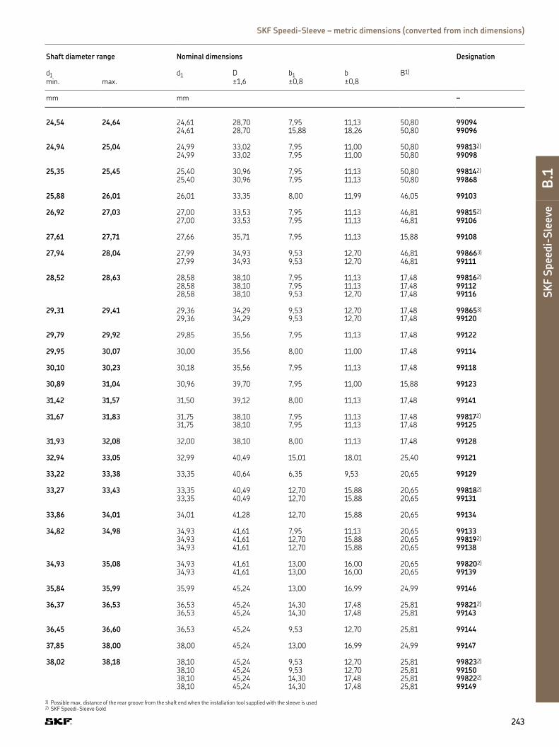
243243
D
E
F
G
H
I
SK
F S
pee
di-
Sle
eve
B.1
SKF Speedi-Sleeve – metric dimensions (converted from inch dimensions)
1) Possible max. distance of the rear groove from the shaft end when the installation tool supplied with the sleeve is used2) SKF Speedi-Sleeve Gold
Shaft diameter range Nominal dimensions Designation
d1 d1 D b1 b B1)
min. max. ±1,6 ±0,8 ±0,8
mm mm –
24,54 24,64 24,61 28,70 7,95 11,13 50,80 9909424,61 28,70 15,88 18,26 50,80 99096
24,94 25,04 24,99 33,02 7,95 11,00 50,80 998132)
24,99 33,02 7,95 11,00 50,80 99098
25,35 25,45 25,40 30,96 7,95 11,13 50,80 998142)
25,40 30,96 7,95 11,13 50,80 99868
25,88 26,01 26,01 33,35 8,00 11,99 46,05 99103
26,92 27,03 27,00 33,53 7,95 11,13 46,81 998152)
27,00 33,53 7,95 11,13 46,81 99106
27,61 27,71 27,66 35,71 7,95 11,13 15,88 99108
27,94 28,04 27,99 34,93 9,53 12,70 46,81 998663)
27,99 34,93 9,53 12,70 46,81 99111
28,52 28,63 28,58 38,10 7,95 11,13 17,48 998162)
28,58 38,10 7,95 11,13 17,48 9911228,58 38,10 9,53 12,70 17,48 99116
29,31 29,41 29,36 34,29 9,53 12,70 17,48 998653)
29,36 34,29 9,53 12,70 17,48 99120
29,79 29,92 29,85 35,56 7,95 11,13 17,48 99122
29,95 30,07 30,00 35,56 8,00 11,00 17,48 99114
30,10 30,23 30,18 35,56 7,95 11,13 17,48 99118
30,89 31,04 30,96 39,70 7,95 11,00 15,88 99123
31,42 31,57 31,50 39,12 8,00 11,13 17,48 99141
31,67 31,83 31,75 38,10 7,95 11,13 17,48 998172)
31,75 38,10 7,95 11,13 17,48 99125
31,93 32,08 32,00 38,10 8,00 11,13 17,48 99128
32,94 33,05 32,99 40,49 15,01 18,01 25,40 99121
33,22 33,38 33,35 40,64 6,35 9,53 20,65 99129
33,27 33,43 33,35 40,49 12,70 15,88 20,65 998182)
33,35 40,49 12,70 15,88 20,65 99131
33,86 34,01 34,01 41,28 12,70 15,88 20,65 99134
34,82 34,98 34,93 41,61 7,95 11,13 20,65 9913334,93 41,61 12,70 15,88 20,65 998192)
34,93 41,61 12,70 15,88 20,65 99138
34,93 35,08 34,93 41,61 13,00 16,00 20,65 998202)
34,93 41,61 13,00 16,00 20,65 99139
35,84 35,99 35,99 45,24 13,00 16,99 24,99 99146
36,37 36,53 36,53 45,24 14,30 17,48 25,81 998212)
36,53 45,24 14,30 17,48 25,81 99143
36,45 36,60 36,53 45,24 9,53 12,70 25,81 99144
37,85 38,00 38,00 45,24 13,00 16,99 24,99 99147
38,02 38,18 38,10 45,24 9,53 12,70 25,81 998232)
38,10 45,24 9,53 12,70 25,81 9915038,10 45,24 14,30 17,48 25,81 998222)
38,10 45,24 14,30 17,48 25,81 99149

b1B
b
D d1
rmax 3,18 mm
All sleeves listed in the product table can be manufactured as both standard and Gold version.
244244
1) Possible max. distance of the rear groove from the shaft end when the installation tool supplied with the sleeve is used2) SKF Speedi-Sleeve Gold
Wear sleeves | SKF Speedi-Sleeve – metric dimensions (converted from inch dimensions)
d1 38,61–59,26 mm
Shaft diameter range Nominal dimensions Designation
d1 d1 D b1 b B1)
min. max. ±1,6 ±0,8 ±0,8
mm mm –
38,61 38,76 38,68 47,22 11,13 14,30 25,81 99152
39,34 39,50 39,42 47,22 11,13 14,30 25,81 99155
39,60 39,75 39,67 47,22 14,30 17,48 25,81 998242)
39,67 47,22 14,30 17,48 25,81 99156
39,78 39,93 39,85 47,22 15,88 19,05 25,81 99159
39,85 40,01 40,01 46,99 9,91 12,93 25,40 99153
39,93 40,08 40,08 46,99 13,00 16,00 25,98 998252)
40,08 46,99 13,00 16,00 25,98 99157
40,69 40,84 40,77 49,23 12,70 16,28 25,40 99160
40,84 41,00 41,00 49,23 12,70 15,88 25,81 99163
41,20 41,35 41,28 47,63 7,95 11,13 25,81 9916141,28 47,63 14,30 17,48 20,65 998262)
41,28 47,63 14,30 17,48 20,65 99162
41,83 42,01 41,91 53,01 11,30 14,50 21,49 9916641,91 53,01 14,30 17,50 21,01 9916942,01 53,01 14,30 17,50 21,01 998732)
41,99 42,14 42,06 53,01 13,97 17,50 21,01 99165
42,77 42,93 42,88 48,41 14,30 17,48 22,23 99168
42,80 42,95 42,88 48,41 7,95 11,13 22,23 99167
42,85 43,00 43,00 48,41 12,70 15,88 21,44 99182
43,56 43,71 43,66 51,59 14,30 17,48 20,65 99171
44,09 44,25 44,17 52,40 9,53 12,70 20,65 99170
44,37 44,53 44,45 52,20 9,53 12,70 20,65 9917244,45 52,40 13,49 15,88 22,30 9918044,45 52,40 14,30 17,48 20,65 998272)
44,45 52,40 14,30 17,48 20,65 9917444,45 52,40 19,05 22,23 20,65 998282)
44,45 52,40 19,05 22,23 20,65 99175

245245
D
E
F
G
H
I
SK
F S
pee
di-
Sle
eve
B.1
SKF Speedi-Sleeve – metric dimensions (converted from inch dimensions)
1) Possible max. distance of the rear groove from the shaft end when the installation tool supplied with the sleeve is used2) SKF Speedi-Sleeve Gold
Shaft diameter range Nominal dimensions Designation
d1 d1 D b1 b B1)
min. max. ±1,6 ±0,8 ±0,8
mm mm –
44,73 44,88 44,86 52,40 14,30 17,48 20,65 998292)
44,86 52,40 14,30 17,48 20,65 99176
44,93 45,09 45,01 53,01 14,00 16,99 20,62 998302)
45,01 53,01 14,00 16,99 20,62 99177
45,16 45,31 45,24 53,98 16,94 20,32 26,97 99179
45,95 46,10 46,05 53,09 14,30 17,48 25,40 998312)
46,05 53,09 14,30 17,48 25,40 99181
47,17 47,32 47,22 54,76 14,30 17,48 25,40 99185
47,40 47,55 47,45 55,58 22,58 26,04 25,40 99186
47,55 47,70 47,63 55,96 4,45 7,49 18,90 9919047,63 55,96 7,49 10,54 18,90 9918847,63 55,96 9,53 13,11 26,67 9918447,63 55,96 14,30 17,48 25,40 998322)
47,63 55,96 14,30 17,48 25,40 99187
47,93 48,08 48,03 56,01 14,00 16,97 24,99 99189
48,49 48,64 48,56 56,36 9,53 12,70 25,40 99192
49,12 49,28 49,23 56,36 14,30 17,48 25,40 998332)
49,23 56,36 14,30 17,48 25,40 99193
49,91 50,06 50,01 56,49 14,00 16,97 34,29 9905250,01 57,00 14,00 16,97 24,99 99196
50,22 50,37 50,29 58,75 14,30 17,88 26,67 99198
50,72 50,88 50,80 61,11 14,30 17,48 25,55 998342)
50,80 61,11 14,30 17,48 25,40 9919950,80 61,11 22,23 25,40 25,40 998352)
50,80 61,11 22,23 25,40 25,40 99200
51,82 51,99 51,99 62,71 12,70 15,88 34,52 99878
52,25 52,40 52,40 62,71 19,84 23,83 34,93 99205
53,92 54,05 53,98 61,52 12,70 19,05 32,54 99210
53,95 54,10 53,98 61,52 19,84 23,83 34,93 998362)
53,98 61,52 19,84 23,83 34,93 9921254,91 55,07 54,99 62,00 19,99 22,99 31,75 998632)
54,99 62,00 19,99 22,99 31,75 99215
55,52 55,68 55,58 63,50 19,84 23,83 33,35 99218
55,83 56,01 56,01 64,29 12,70 15,88 33,35 9922056,01 64,29 19,79 23,77 80,01 99224
56,57 56,72 56,64 64,29 12,70 15,88 33,35 998612)
56,64 64,29 12,70 15,88 33,35 9922956,64 64,29 19,84 23,01 31,75 99230
56,82 56,97 56,90 65,10 19,41 22,86 31,75 99226
57,12 57,28 57,15 64,29 7,95 11,13 33,35 998382)
57,15 64,29 7,95 11,13 33,35 9922757,15 64,29 19,84 23,83 33,35 998372)
57,15 64,29 19,84 23,83 33,35 99225
57,91 58,06 57,99 65,99 19,99 23,83 34,93 99219
58,65 58,80 58,75 68,28 19,84 23,83 34,93 99231
59,11 59,26 59,13 69,85 19,05 22,23 38,10 99233

b1B
b
D d1
rmax 3,18 mm
All sleeves listed in the product table can be manufactured as both standard and Gold version.
246246
1) Possible max. distance of the rear groove from the shaft end when the installation tool supplied with the sleeve is used2) SKF Speedi-Sleeve Gold
Wear sleeves | SKF Speedi-Sleeve – metric dimensions (converted from inch dimensions)
d1 59,92–82,63 mm
Shaft diameter range Nominal dimensions Designation
d1 d1 D b1 b B1)
min. max. ±1,6 ±0,8 ±0,8
mm mm –
59,92 60,07 59,99 70,74 9,40 11,43 37,36 9924159,99 70,74 19,99 22,99 34,93 998692)
59,99 70,74 19,99 22,99 34,93 99235
60,25 60,40 60,33 69,85 15,09 19,05 34,93 99238
60,30 60,45 60,33 69,85 13,36 17,35 34,93 9924060,33 69,85 19,84 23,83 34,93 998392)
60,33 69,85 19,84 23,83 34,93 99237
61,82 62,00 61,93 71,83 19,84 23,83 35,38 9924362,00 71,83 12,70 15,88 36,20 99244
61,85 62,00 61,93 71,83 12,70 15,88 36,20 99242
63,22 63,37 63,30 73,03 19,84 23,83 35,38 99249
63,42 63,58 63,50 71,63 14,10 16,51 22,61 99253
63,50 63,65 63,50 71,83 12,70 16,66 35,38 9924863,50 71,63 19,84 23,83 34,93 998402)
63,50 71,63 19,84 23,83 34,93 99250
63,75 63,91 63,91 71,83 19,84 23,01 36,53 99251
64,92 65,07 65,00 72,39 19,99 22,99 34,93 998412)
65,00 72,39 19,99 22,99 34,93 99254
65,02 65,18 65,10 73,43 19,84 23,83 34,93 99256
65,91 66,07 65,99 75,95 19,84 23,83 31,75 99259
66,50 66,65 66,57 77,39 19,84 23,83 34,93 99261
66,57 66,73 66,68 77,39 19,84 23,01 34,93 99264
66,60 66,75 66,68 77,39 12,70 15,88 34,93 99260
66,68 66,83 66,68 77,39 19,84 23,83 34,93 998422)
66,68 77,39 19,84 23,83 34,93 99262
67,82 68,00 68,00 79,38 19,05 22,23 42,88 99266
69,27 69,42 69,34 79,38 19,84 23,01 33,35 99268

247247
D
E
F
G
H
I
SK
F S
pee
di-
Sle
eve
B.1
SKF Speedi-Sleeve – metric dimensions (converted from inch dimensions)
1) Possible max. distance of the rear groove from the shaft end when the installation tool supplied with the sleeve is used2) SKF Speedi-Sleeve Gold
Shaft diameter range Nominal dimensions Designation
d1 d1 D b1 b B1)
min. max. ±1,6 ±0,8 ±0,8
mm mm –
69,60 69,75 69,67 77,85 19,84 23,83 31,75 99273
69,72 69,88 69,85 79,38 19,84 23,83 31,75 998432)
69,85 79,38 19,84 23,83 31,75 99274
69,77 69,93 69,85 78,11 36,53 41,28 41,28 99267
69,85 70,00 69,85 79,38 10,31 14,30 31,75 9927269,85 79,38 19,84 23,83 31,75 998442)
69,85 79,38 19,84 23,83 31,75 9927569,85 79,38 28,58 31,75 33,32 99269
69,93 70,08 70,00 79,38 19,99 24,00 31,75 99276
71,35 71,50 71,45 80,98 15,09 17,48 31,75 99281
71,83 72,01 72,01 81,92 19,05 22,23 34,11 998702)
72,01 81,92 19,05 22,23 34,11 99284
72,09 72,24 72,09 81,92 12,70 16,66 31,75 998452)
72,09 81,92 12,70 16,66 31,75 99282
72,80 72,95 72,87 80,98 19,84 23,83 31,75 99286
72,97 73,13 73,03 81,76 19,84 23,83 31,75 998462)
73,03 81,76 19,84 23,83 31,75 99287
74,60 74,75 74,63 84,94 12,70 16,28 33,81 9929074,63 84,94 19,84 23,83 33,35 998472)
74,68 84,94 19,84 23,83 33,35 99293
74,93 75,08 75,01 83,13 15,09 17,53 27,51 9928975,01 83,95 22,00 26,01 33,35 998752)
75,01 83,95 22,00 26,01 33,35 99294
75,49 75,59 75,54 82,17 20,65 25,40 31,75 99292
75,95 76,10 76,02 85,32 12,29 15,88 33,81 9929176,02 85,32 14,30 17,48 34,93 9929876,02 85,09 20,65 25,40 32,54 99299
76,12 76,28 76,20 82,30 20,65 23,83 34,93 99296
76,20 76,35 76,20 84,96 15,88 20,65 32,51 9904876,20 82,17 20,65 25,40 32,54 998482)
76,20 82,17 20,65 25,40 32,54 99300
76,40 76,56 76,48 85,22 12,70 15,88 50,80 99301
77,83 78,00 78,00 88,09 19,05 22,23 52,22 99306
79,25 79,40 79,38 89,69 17,48 20,65 50,80 9931179,38 89,69 20,65 25,40 50,80 998492)
79,38 89,69 20,65 25,40 50,80 99312
79,35 79,55 79,38 89,54 14,00 18,01 51,59 99053
79,81 80,01 80,01 89,92 19,05 22,50 34,93 99313
79,91 80,09 80,01 89,99 11,00 15,01 34,93 9931780,01 89,99 21,01 24,00 34,93 99315
81,92 82,07 81,99 91,06 16,76 21,54 44,45 99328
82,47 82,63 82,55 91,29 20,65 25,40 34,93 99322

b1B
b
D d1
rmax 3,18 mm
All sleeves listed in the product table can be manufactured as both standard and Gold version.
248248
1) Possible max. distance of the rear groove from the shaft end when the installation tool supplied with the sleeve is used2) SKF Speedi-Sleeve Gold
Wear sleeves | SKF Speedi-Sleeve – metric dimensions (converted from inch dimensions)
d1 82,55–123,11 mm
Shaft diameter range Nominal dimensions Designation
d1 d1 D b1 b B1)
min. max. ±1,6 ±0,8 ±0,8
mm mm –
82,55 82,70 82,55 90,81 15,11 18,26 34,93 998502)
82,55 90,81 15,11 18,26 34,93 9932482,55 91,06 17,48 22,23 31,75 9932682,55 91,06 20,65 25,40 34,93 998512)
82,55 91,06 20,65 25,40 34,93 99325
84,00 84,15 84,07 93,68 20,65 25,40 34,93 99331
84,76 85,01 84,89 93,98 16,99 21,01 35,00 9933284,89 93,98 21,01 24,99 35,00 998722)
84,89 93,98 21,01 24,99 35,00 99333
84,79 85,01 85,01 90,93 10,13 12,67 36,35 99334
85,67 85,83 85,73 93,68 9,53 12,70 35,81 9933885,73 93,85 20,65 25,40 34,93 99337
87,25 87,40 87,33 97,64 19,84 23,01 35,71 99339
87,80 88,00 88,00 95,28 29,21 34,27 42,50 99481
88,32 88,47 88,39 97,41 19,84 23,01 35,71 99340
88,82 88,98 88,90 97,64 15,88 20,65 34,21 99346
88,90 89,05 88,90 97,16 7,95 12,70 34,21 9934788,90 97,64 20,65 25,40 34,21 998522)
88,90 97,64 20,65 25,40 34,21 99350
88,93 89,08 89,00 97,64 15,88 20,65 34,24 99349
89,92 90,07 89,99 101,60 11,13 13,67 46,05 9935289,99 101,60 13,36 16,94 44,45 9935389,99 101,60 18,03 23,01 46,05 9935189,99 101,60 23,01 27,99 44,45 99354
90,42 90,58 90,50 99,06 20,65 25,40 44,45 99356
91,90 92,05 91,97 102,39 20,65 25,40 44,45 99360
92,02 92,18 92,08 102,24 12,70 15,88 44,45 9936392,08 102,39 20,65 25,40 44,45 99362
93,57 93,73 93,68 102,39 7,95 11,13 22,23 99368

249249
D
E
F
G
H
I
SK
F S
pee
di-
Sle
eve
B.1
SKF Speedi-Sleeve – metric dimensions (converted from inch dimensions)
1) Possible max. distance of the rear groove from the shaft end when the installation tool supplied with the sleeve is used2) SKF Speedi-Sleeve Gold
Shaft diameter range Nominal dimensions Designation
d1 d1 D b1 b B1)
min. max. ±1,6 ±0,8 ±0,8
mm mm –
93,60 93,75 93,68 102,24 20,65 23,83 45,72 99365
94,67 94,82 94,74 102,01 11,91 15,09 45,72 9935994,74 102,24 19,84 23,01 45,72 99366
94,92 95,07 95,00 102,24 21,01 24,00 45,72 99369
95,00 95,15 95,07 102,39 8,74 12,70 45,72 9937495,07 102,49 11,91 15,09 45,72 99364
95,15 95,30 95,22 102,24 14,30 17,48 45,72 99376
95,25 95,40 95,25 102,11 17,48 22,23 45,72 998532)
95,33 102,24 8,74 12,70 45,72 9936795,33 102,11 17,48 22,23 45,72 99372
98,25 98,40 98,32 106,30 20,65 25,40 47,63 99386
98,37 98,53 98,43 107,16 20,65 25,40 47,63 99387
99,95 100,10 100,03 109,55 20,65 25,40 52,07 998542)
100,03 109,55 20,65 25,40 52,07 99393
101,55 101,75 101,60 111,13 12,70 15,88 52,48 99401101,60 111,13 15,24 18,42 52,07 99395101,60 111,13 16,51 19,69 34,93 99400101,60 111,13 20,65 25,40 52,07 998552)
101,60 111,13 20,65 25,40 52,07 99399
103,89 104,09 103,99 112,73 19,99 24,00 35,99 99409
104,70 104,90 104,78 113,54 20,65 25,40 34,93 99412
104,90 105,11 105,00 113,54 19,99 23,19 35,00 99413
106,25 106,45 106,38 114,30 20,65 25,40 34,93 99418
107,34 107,54 107,54 117,09 19,84 23,01 36,53 99423
107,90 108,10 107,95 117,09 20,65 25,40 36,53 99424
109,78 110,01 110,01 124,99 11,38 14,96 32,94 99434
109,91 110,11 109,93 124,99 12,93 16,51 31,75 99435
111,00 111,20 111,13 120,65 20,65 25,40 41,91 99437
111,79 111,99 111,99 120,65 19,05 22,50 33,02 99438
112,62 112,83 112,73 122,25 25,40 29,01 33,35 99439
114,20 114,40 114,30 123,19 20,65 25,40 31,75 998562)
114,30 124,46 20,65 25,40 31,75 99450
114,88 115,09 115,01 127,00 20,65 23,83 31,75 99452
117,37 117,58 117,48 127,00 11,13 15,88 34,93 99465117,48 128,60 25,40 31,75 34,93 99463
119,00 119,20 119,08 128,60 20,65 25,40 34,93 99468
119,89 120,09 119,99 129,79 8,00 11,00 33,60 99471119,99 129,79 19,99 24,99 32,00 99473
120,55 120,75 120,65 127,00 12,70 19,05 38,10 99475
121,89 122,10 122,00 131,50 19,99 24,00 32,00 99472
122,91 123,11 123,01 132,82 19,99 24,99 31,60 99484

b1B
b
D d1
rmax 3,18 mm
All sleeves listed in the product table can be manufactured as both standard and Gold version.
250250
1) Possible max. distance of the rear groove from the shaft end when the installation tool supplied with the sleeve is used2) SKF Speedi-Sleeve Gold
Wear sleeves | SKF Speedi-Sleeve – metric dimensions (converted from inch dimensions)
d1 123,72–203,33 mm
Shaft diameter range Nominal dimensions Designation
d1 d1 D b1 b B1)
min. max. ±1,6 ±0,8 ±0,8
mm mm –
123,72 123,93 123,83 133,35 15,88 19,05 36,53 99487
124,89 125,10 124,99 137,16 10,01 14,00 36,53 99490124,99 137,16 26,01 32,00 36,53 99492
126,95 127,15 127,00 137,16 13,72 17,30 36,53 99501127,00 137,16 17,48 22,23 36,53 998572)
127,00 137,16 17,48 22,23 36,53 99498127,00 136,91 20,65 25,40 36,53 998582)
127,00 136,91 20,65 25,40 36,53 99499
127,80 128,00 128,00 135,26 29,21 34,27 40,30 99482
129,79 130,00 129,90 139,52 19,05 23,83 30,00 99494
129,97 130,18 130,00 139,52 22,00 25,30 32,51 998742)
130,18 139,52 22,00 25,30 32,51 99491
130,05 130,25 130,18 139,70 20,65 25,40 31,75 99513
133,25 133,45 133,35 141,22 20,65 25,40 31,75 99525
134,80 135,00 134,90 145,67 20,50 25,40 31,75 99533
136,42 136,63 136,53 149,23 20,65 25,40 31,75 99537
138,02 138,23 138,13 146,05 38,10 42,88 47,63 99548
138,99 139,19 139,09 149,86 14,30 19,05 31,34 99547
139,65 139,85 139,70 150,83 13,16 17,91 31,75 99550139,70 150,83 20,65 25,40 31,75 998592)
139,70 150,83 20,65 25,40 31,75 99549
139,90 140,11 140,00 151,00 20,50 25,40 31,75 99552
142,77 142,98 142,88 157,18 22,23 25,40 46,02 99560
144,75 145,01 145,01 154,94 19,05 22,23 46,02 99571
145,44 145,64 145,64 154,94 14,30 19,05 49,23 99562
145,95 146,15 146,05 156,97 20,65 25,40 44,45 99575

251251
D
E
F
G
H
I
SK
F S
pee
di-
Sle
eve
B.1
SKF Speedi-Sleeve – metric dimensions (converted from inch dimensions)
1) Possible max. distance of the rear groove from the shaft end when the installation tool supplied with the sleeve is used2) SKF Speedi-Sleeve Gold
Shaft diameter range Nominal dimensions Designation
d1 d1 D b1 b B1)
min. max. ±1,6 ±0,8 ±0,8
mm mm –
149,12 149,33 149,23 157,18 25,40 31,75 33,35 998622)
149,23 157,18 25,40 31,75 33,35 99587
149,76 150,01 149,99 159,00 26,01 30,00 32,51 99595
150,72 150,93 150,83 161,93 25,40 28,58 47,63 99596
152,27 152,48 152,40 161,54 12,70 19,05 44,45 99601152,40 161,93 25,40 31,75 44,45 99599
153,87 154,13 154,00 161,93 26,01 30,00 32,99 99605
154,74 154,99 154,86 167,01 26,01 30,00 32,99 99606
157,43 157,68 157,56 168,28 20,65 27,00 44,45 99620
158,62 158,88 158,75 168,28 26,19 31,75 44,45 99625
159,74 159,99 159,99 171,45 25,40 31,75 34,93 99630
164,97 165,23 165,10 177,80 25,40 31,75 34,93 99650
169,75 170,00 169,88 182,58 31,75 38,00 44,45 99640
171,32 171,58 171,45 180,98 20,65 27,00 44,45 99675
174,75 175,01 175,01 186,99 27,99 32,00 35,00 99687
177,67 177,93 177,80 189,87 25,40 31,75 42,88 998642)
177,80 189,87 25,40 31,75 42,88 99700
179,76 180,01 180,01 190,50 32,99 38,00 44,50 99721
184,00 184,25 184,15 197,10 31,75 38,10 55,25 99725
184,73 184,99 184,86 197,10 32,00 38,00 54,99 99726
189,08 189,33 189,31 199,64 20,65 25,40 31,75 99745
190,37 190,63 190,50 200,03 20,65 25,40 31,75 99750
196,72 196,98 196,85 210,06 25,40 33,35 47,63 99775
199,87 200,13 200,03 212,73 34,52 38,10 44,45 99787
201,50 201,75 201,63 212,73 25,40 31,75 44,45 99799
203,07 203,33 203,20 212,73 25,40 31,75 44,45 99800

b1B
b
D d1
rmax 0.125 in.
All sleeves listed in the product table can be manufactured as both standard and Gold version.
252252
1) Possible max. distance of the rear groove from the shaft end when the installation tool supplied with the sleeve is used2) SKF Speedi-Sleeve Gold
Wear sleeves | SKF Speedi-Sleeve – inch dimensions
d1 0.472–1.496
Shaft diameter range Nominal dimensions Designation
d1 d1 D b1 b B1)
min. max. ±0.063 ±0.031 ±0.031
in in –
0.472 0.475 0.472 0.610 0.236 0.331 1.875 99049
0.498 0.502 0.500 0.610 0.250 0.344 2.000 99050
0.547 0.551 0.551 0.750 0.250 0.391 1.831 99055
0.560 0.566 0.563 0.750 0.250 0.391 1.831 99056
0.589 0.593 0.591 0.750 0.197 0.354 1.862 99059
0.623 0.627 0.625 0.750 0.313 0.406 2.000 998102)
0.625 0.750 0.313 0.406 2.000 99062
0.626 0.630 0.630 0.718 0.313 0.438 2.000 99058
0.667 0.671 0.669 0.875 0.315 0.433 2.000 99068
0.682 0.686 0.684 0.900 0.313 0.438 2.000 99060
0.704 0.709 0.709 0.962 0.315 0.433 1.811 99082
0.748 0.752 0.750 0.945 0.313 0.438 2.000 998112)
0.750 0.945 0.313 0.438 2.000 99076
0.759 0.761 0.760 0.938 0.313 0.438 2.000 99081
0.780 0.784 0.781 0.935 0.313 0.438 2.000 99080
0.785 0.789 0.787 0.930 0.315 0.433 2.000 99078
0.812 0.815 0.813 1.188 0.375 0.563 3.000 99083
0.857 0.861 0.859 1.155 0.250 0.375 2.000 99086
0.861 0.866 0.866 1.188 0.259 0.359 1.856 990840.866 1.188 0.315 0.472 1.812 99085
0.873 0.877 0.875 1.094 0.313 0.438 2.000 998122)
0.875 1.094 0.313 0.438 2.000 99087
0.908 0.912 0.910 1.218 0.313 0.438 1.847 998602)
0.910 1.218 0.313 0.438 1.847 99091

253253
D
E
F
G
H
I
SK
F S
pee
di-
Sle
eve
B.1
SKF Speedi-Sleeve – inch dimensions
1) Possible max. distance of the rear groove from the shaft end when the installation tool supplied with the sleeve is used2) SKF Speedi-Sleeve Gold
Shaft diameter range Nominal dimensions Designation
d1 d1 D b1 b B1)
min. max. ±0.063 ±0.031 ±0.031
in in –
0.940 0.945 0.945 1.130 0.313 0.438 2.000 99092
0.966 0.970 0.969 1.130 0.313 0.438 2.000 990940.969 1.130 0.625 0.719 2.000 99096
0.982 0.986 0.984 1.300 0.313 0.433 2.000 998132)
0.984 1.300 0.313 0.433 2.000 99098
0.998 1.002 1.000 1.219 0.313 0.438 2.000 998142)
1.000 1.219 0.313 0.438 2.000 99868
1.019 1.024 1.024 1.313 0.315 0.472 1.813 99103
1.060 1.064 1.063 1.320 0.313 0.438 1.843 998152)
1.063 1.320 0.313 0.438 1.843 99106
1.087 1.091 1.089 1.406 0.313 0.438 0.625 99108
1.100 1.104 1.102 1.375 0.375 0.500 1.843 998662)
1.102 1.375 0.375 0.500 1.843 99111
1.123 1.127 1.125 1.500 0.313 0.438 0.688 998162)
1.125 1.500 0.313 0.438 0.688 991121.125 1.500 0.375 0.500 0.688 99116
1.154 1.158 1.156 1.350 0.375 0.500 0.688 998652)
1.156 1.350 0.375 0.500 0.688 99120
1.173 1.178 1.175 1.400 0.313 0.438 0.688 99122
1.179 1.184 1.181 1.400 0.315 0.433 0.688 99114
1.185 1.190 1.188 1.400 0.313 0.438 0.688 99118
1.216 1.222 1.219 1.563 0.313 0.433 0.625 99123
1.237 1.243 1.240 1.540 0.315 0.438 0.688 99141
1.247 1.253 1.250 1.500 0.313 0.438 0.688 998172)
1.250 1.500 0.313 0.438 0.688 99125
1.257 1.263 1.260 1.500 0.315 0.438 0.688 99128
1.297 1.301 1.299 1.594 0.591 0.709 1.000 99121
1.308 1.314 1.313 1.600 0.250 0.375 0.813 99129
1.310 1.316 1.313 1.594 0.500 0.625 0.813 998182)
1.313 1.594 0.500 0.625 0.813 99131
1.333 1.339 1.339 1.625 0.500 0.625 0.813 99134
1.371 1.377 1.375 1.638 0.313 0.438 0.813 991331.375 1.638 0.500 0.625 0.813 998192)
1.375 1.638 0.500 0.625 0.813 99138
1.375 1.381 1.375 1.638 0.512 0.630 0.813 998202)
1.375 1.638 0.512 0.630 0.813 99139
1.411 1.417 1.417 1.781 0.512 0.669 0.984 99146
1.432 1.438 1.438 1.781 0.563 0.688 1.016 998212)
1.438 1.781 0.563 0.688 1.016 99143
1.435 1.441 1.438 1.781 0.375 0.500 1.016 99144
1.490 1.496 1.496 1.781 0.512 0.669 0.984 99147

b1B
b
D d1
rmax 0.125 in.
All sleeves listed in the product table can be manufactured as both standard and Gold version.
254254
1) Possible max. distance of the rear groove from the shaft end when the installation tool supplied with the sleeve is used2) SKF Speedi-Sleeve Gold
Wear sleeves | SKF Speedi-Sleeve – inch dimensions
d1 1.497–2.243
Shaft diameter range Nominal dimensions Designation
d1 d1 D b1 b B1)
min. max. ±0.063 ±0.031 ±0.031
in in –
1.497 1.503 1.500 1.781 0.375 0.500 1.016 998232)
1.500 1.781 0.375 0.500 1.016 991501.500 1.781 0.563 0.688 1.016 998222)
1.500 1.781 0.563 0.688 1.016 99149
1.520 1.526 1.523 1.859 0.438 0.563 1.016 99152
1.549 1.555 1.552 1.859 0.438 0.563 1.016 99155
1.559 1.565 1.562 1.859 0.563 0.688 1.016 998242)
1.562 1.859 0.563 0.688 1.016 99156
1.566 1.572 1.569 1.859 0.625 0.750 1.016 99159
1.569 1.575 1.575 1.850 0.390 0.509 1.000 99153
1.572 1.578 1.578 1.850 0.512 0.630 1.023 998252)
1.578 1.850 0.512 0.630 1.023 99157
1.602 1.608 1.605 1.938 0.500 0.641 1.000 99160
1.608 1.614 1.614 1.938 0.500 0.625 1.016 99163
1.622 1.628 1.625 1.875 0.313 0.438 1.016 991611.625 1.875 0.563 0.688 0.813 998262)
1.625 1.875 0.563 0.688 0.813 99162
1.647 1.654 1.650 2.087 0.445 0.571 0.846 991661.650 2.087 0.563 0.689 0.827 991691.654 2.087 0.563 0.689 0.827 998732)
1.653 1.659 1.656 2.087 0.550 0.689 0.827 99165
1.684 1.690 1.688 1.906 0.563 0.688 0.875 99168
1.685 1.691 1.688 1.906 0.313 0.438 0.875 99167
1.687 1.693 1.693 1.906 0.500 0.625 0.844 99182
1.715 1.721 1.719 2.031 0.563 0.688 0.813 99171
1.736 1.742 1.739 2.063 0.375 0.500 0.813 99170
1.747 1.753 1.750 2.055 0.375 0.500 0.813 99172

255255
D
E
F
G
H
I
SK
F S
pee
di-
Sle
eve
B.1
SKF Speedi-Sleeve – inch dimensions
1) Possible max. distance of the rear groove from the shaft end when the installation tool supplied with the sleeve is used2) SKF Speedi-Sleeve Gold
Shaft diameter range Nominal dimensions Designation
d1 d1 D b1 b B1)
min. max. ±0.063 ±0.031 ±0.031
in in –
1.750 2.063 0.531 0.625 0.878 991801.750 2.063 0.563 0.688 0.813 998272)
1.750 2.063 0.563 0.688 0.813 991741.750 2.063 0.750 0.875 0.813 998282)
1.750 2.063 0.750 0.875 0.813 99175
1.761 1.767 1.766 2.063 0.563 0.688 0.813 998292)
1.766 2.063 0.563 0.688 0.813 99176
1.769 1.775 1.772 2.087 0.551 0.669 0.812 998302)
1.772 2.087 0.551 0.669 0.812 99177
1.778 1.784 1.781 2.125 0.667 0.800 1.062 99179
1.809 1.815 1.813 2.090 0.563 0.688 1.000 998312)
1.813 2.090 0.563 0.688 1.000 99181
1.857 1.863 1.859 2.156 0.563 0.688 1.000 99185
1.866 1.872 1.868 2.188 0.889 1.025 1.000 99186
1.872 1.878 1.875 2.203 0.175 0.295 0.744 991901.875 2.203 0.295 0.415 0.744 991881.875 2.203 0.375 0.516 1.050 991841.875 2.203 0.563 0.688 1.000 998322)
1.875 2.203 0.563 0.688 1.000 99187
1.887 1.893 1.891 2.205 0.551 0.668 0.984 99189
1.909 1.915 1.912 2.219 0.375 0.500 1.000 99192
1.934 1.940 1.938 2.219 0.563 0.688 1.000 998332)
1.938 2.219 0.563 0.688 1.000 99193
1.965 1.971 1.969 2.244 0.551 0.668 1.350 990521.969 2.244 0.551 0.668 0.984 99196
1.977 1.983 1.980 2.313 0.563 0.704 1.050 99198
1.997 2.003 2.000 2.406 0.563 0.688 1.006 998342)
2.000 2.406 0.563 0.688 1.000 991992.000 2.406 0.875 1.000 1.000 998352)
2.000 2.406 0.875 1.000 1.000 99200
2.040 2.047 2.047 2.469 0.500 0.625 1.359 99878
2.057 2.063 2.063 2.469 0.781 0.938 1.375 99205
2.123 2.128 2.125 2.422 0.500 0.750 1.281 99210
2.124 2.130 2.125 2.422 0.781 0.938 1.375 998362)
2.125 2.422 0.781 0.938 1.375 99212
2.162 2.168 2.165 2.441 0.787 0.905 1.250 998632)
2.165 2.441 0.787 0.905 1.250 99215
2.186 2.192 2.188 2.500 0.781 0.938 1.313 99218
2.198 2.205 2.205 2.531 0.500 0.625 1.313 992202.205 2.531 0.779 0.936 3.150 99224
2.227 2.233 2.230 2.531 0.500 0.625 1.313 998612)
2.230 2.531 0.500 0.625 1.313 992292.230 2.531 0.781 0.906 1.250 99230
2.237 2.243 2.240 2.563 0.764 0.900 1.250 99226

b1B
b
D d1
rmax 0.125 in.
All sleeves listed in the product table can be manufactured as both standard and Gold version.
256256
1) Possible max. distance of the rear groove from the shaft end when the installation tool supplied with the sleeve is used2) SKF Speedi-Sleeve Gold
Wear sleeves | SKF Speedi-Sleeve – inch dimensions
d1 2.249–3.150
Shaft diameter range Nominal dimensions Designation
d1 d1 D b1 b B1)
min. max. ±0.063 ±0.031 ±0.031
in in –
2.249 2.255 2.250 2.531 0.313 0.438 1.313 998382)
2.250 2.531 0.313 0.438 1.313 992272.250 2.531 0.781 0.938 1.313 998372)
2.250 2.531 0.781 0.938 1.313 99225
2.280 2.286 2.283 2.598 0.787 0.938 1.375 99219
2.309 2.315 2.313 2.688 0.781 0.938 1.375 99231
2.327 2.333 2.328 2.750 0.750 0.875 1.500 99233
2.359 2.365 2.362 2.785 0.370 0.450 1.471 992412.362 2.785 0.787 0.905 1.375 998692)
2.362 2.785 0.787 0.905 1.375 99235
2.372 2.378 2.375 2.750 0.594 0.750 1.375 99238
2.374 2.380 2.375 2.750 0.526 0.683 1.375 992402.375 2.750 0.781 0.938 1.375 998392)
2.375 2.750 0.781 0.938 1.375 99237
2.434 2.441 2.438 2.828 0.781 0.938 1.393 992432.441 2.828 0.500 0.625 1.425 99244
2.435 2.441 2.438 2.828 0.500 0.625 1.425 992422.489 2.495 2.492 2.875 0.781 0.938 1.393 99249
2.497 2.503 2.500 2.820 0.555 0.650 0.890 99253
2.500 2.506 2.500 2.828 0.500 0.656 1.393 992482.500 2.820 0.781 0.938 1.375 998402)
2.500 2.820 0.781 0.938 1.375 99250
2.510 2.516 2.516 2.828 0.781 0.906 1.438 99251
2.556 2.562 2.559 2.850 0.787 0.905 1.375 998412)
2.559 2.850 0.787 0.905 1.375 99254
2.560 2.566 2.563 2.891 0.781 0.938 1.375 99256
2.595 2.601 2.598 2.990 0.781 0.938 1.250 99259
2.618 2.624 2.621 3.047 0.781 0.938 1.375 99261

257257
D
E
F
G
H
I
SK
F S
pee
di-
Sle
eve
B.1
SKF Speedi-Sleeve – inch dimensions
1) Possible max. distance of the rear groove from the shaft end when the installation tool supplied with the sleeve is used2) SKF Speedi-Sleeve Gold
Shaft diameter range Nominal dimensions Designation
d1 d1 D b1 b B1)
min. max. ±0.063 ±0.031 ±0.031
in in –
2.621 2.627 2.625 3.047 0.781 0.906 1.375 99264
2.622 2.628 2.625 3.047 0.500 0.625 1.375 99260
2.625 2.631 2.625 3.047 0.781 0.938 1.375 998422)
2.625 3.047 0.781 0.938 1.375 99262
2.670 2.677 2.677 3.125 0.750 0.875 1.688 99266
2.727 2.733 2.730 3.125 0.781 0.906 1.313 99268
2.740 2.746 2.743 3.065 0.781 0.938 1.250 99273
2.745 2.751 2.750 3.125 0.781 0.938 1.250 998432)
2.750 3.125 0.781 0.938 1.250 99274
2.747 2.753 2.750 3.075 1.438 1.625 1.625 99267
2.750 2.756 2.750 3.125 0.406 0.563 1.250 992722.750 3.125 0.781 0.938 1.250 998442)
2.750 3.125 0.781 0.938 1.250 992752.750 3.125 1.125 1.250 1.312 99269
2.753 2.759 2.756 3.125 0.787 0.945 1.250 99276
2.809 2.815 2.813 3.188 0.594 0.688 1.250 99281
2.828 2.835 2.835 3.225 0.750 0.875 1.343 998702)
2.835 3.225 0.750 0.875 1.343 99284
2.838 2.844 2.838 3.225 0.500 0.656 1.250 998452)
2.838 3.225 0.500 0.656 1.250 99282
2.866 2.872 2.869 3.188 0.781 0.938 1.250 99286
2.873 2.879 2.875 3.219 0.781 0.938 1.250 998462)
2.875 3.219 0.781 0.938 1.250 99287
2.937 2.943 2.938 3.344 0.500 0.641 1.331 992902.938 3.344 0.781 0.938 1.313 998472)
2.940 3.344 0.781 0.938 1.313 99293
2.950 2.956 2.953 3.273 0.594 0.690 1.083 992892.953 3.305 0.866 1.024 1.313 998752)
2.953 3.305 0.866 1.024 1.313 99294
2.972 2.976 2.974 3.235 0.813 1.000 1.250 99292
2.990 2.996 2.993 3.359 0.484 0.625 1.331 992912.993 3.359 0.563 0.688 1.375 992982.993 3.350 0.813 1.000 1.281 99299
2.997 3.003 3.000 3.240 0.813 0.938 1.375 99296
3.000 3.006 3.000 3.345 0.625 0.813 1.280 990483.000 3.235 0.813 1.000 1.281 998482)
3.000 3.235 0.813 1.000 1.281 99300
3.008 3.014 3.011 3.355 0.500 0.625 2.000 99301
3.064 3.071 3.071 3.468 0.750 0.875 2.056 99306
3.120 3.126 3.125 3.531 0.688 0.813 2.000 993113.125 3.531 0.813 1.000 2.000 998492)
3.125 3.531 0.813 1.000 2.000 99312
3.124 3.132 3.125 3.525 0.551 0.709 2.031 99053
3.142 3.150 3.150 3.540 0.750 0.886 1.375 99313

b1B
b
D d1
rmax 0.125 in.
All sleeves listed in the product table can be manufactured as both standard and Gold version.
258258
1) Possible max. distance of the rear groove from the shaft end when the installation tool supplied with the sleeve is used2) SKF Speedi-Sleeve Gold
Wear sleeves | SKF Speedi-Sleeve – inch dimensions
d1 3.146–4.693
Shaft diameter range Nominal dimensions Designation
d1 d1 D b1 b B1)
min. max. ±0.063 ±0.031 ±0.031
in in –
3.146 3.153 3.150 3.543 0.433 0.591 1.375 993173.150 3.543 0.827 0.945 1.375 99315
3.225 3.231 3.228 3.585 0.660 0.848 1.750 99328
3.247 3.253 3.250 3.594 0.813 1.000 1.375 99322
3.250 3.256 3.250 3.575 0.595 0.719 1.375 998502)
3.250 3.575 0.595 0.719 1.375 993243.250 3.585 0.688 0.875 1.250 993263.250 3.585 0.813 1.000 1.375 998512)
3.250 3.585 0.813 1.000 1.375 99325
3.307 3.313 3.310 3.688 0.813 1.000 1.375 99331
3.337 3.347 3.342 3.700 0.669 0.827 1.378 993323.342 3.700 0.827 0.984 1.378 998722)
3.342 3.700 0.827 0.984 1.378 99333
3.338 3.347 3.347 3.580 0.399 0.499 1.431 99334
3.373 3.379 3.375 3.688 0.375 0.500 1.410 993383.375 3.695 0.813 1.000 1.375 99337
3.435 3.441 3.438 3.844 0.781 0.906 1.406 99339
3.457 3.465 3.465 3.751 1.150 1.349 1.673 99481
3.477 3.483 3.480 3.835 0.781 0.906 1.406 99340
3.497 3.503 3.500 3.844 0.625 0.813 1.347 99346
3.500 3.506 3.500 3.825 0.313 0.500 1.347 993473.500 3.844 0.813 1.000 1.347 998522)
3.500 3.844 0.813 1.000 1.347 99350
3.501 3.507 3.504 3.844 0.625 0.813 1.348 99349
3.540 3.546 3.543 4.000 0.438 0.538 1.813 993523.543 4.000 0.526 0.667 1.750 993533.543 4.000 0.710 0.906 1.813 993513.543 4.000 0.906 1.102 1.750 99354
3.560 3.566 3.563 3.900 0.813 1.000 1.750 99356

259259
D
E
F
G
H
I
SK
F S
pee
di-
Sle
eve
B.1
SKF Speedi-Sleeve – inch dimensions
1) Possible max. distance of the rear groove from the shaft end when the installation tool supplied with the sleeve is used2) SKF Speedi-Sleeve Gold
Shaft diameter range Nominal dimensions Designation
d1 d1 D b1 b B1)
min. max. ±0.063 ±0.031 ±0.031
in in –
3.618 3.624 3.621 4.031 0.813 1.000 1.750 99360
3.623 3.629 3.625 4.025 0.500 0.625 1.750 993633.625 4.031 0.813 1.000 1.750 99362
3.684 3.690 3.688 4.031 0.313 0.438 0.875 99368
3.685 3.691 3.688 4.025 0.813 0.938 1.800 99365
3.727 3.733 3.730 4.016 0.469 0.594 1.800 993593.730 4.025 0.781 0.906 1.800 99366
3.737 3.743 3.740 4.025 0.827 0.945 1.800 99369
3.740 3.746 3.743 4.031 0.344 0.500 1.800 993743.743 4.035 0.469 0.594 1.800 99364
3.746 3.752 3.749 4.025 0.563 0.688 1.800 99376
3.750 3.756 3.750 4.020 0.688 0.875 1.800 998532)
3.753 4.025 0.344 0.500 1.800 993673.753 4.020 0.688 0.875 1.800 99372
3.868 3.874 3.871 4.185 0.813 1.000 1.875 99386
3.873 3.879 3.875 4.219 0.813 1.000 1.875 99387
3.935 3.941 3.938 4.313 0.813 1.000 2.050 998542)
3.938 4.313 0.813 1.000 2.050 99393
3.998 4.006 4.000 4.375 0.500 0.625 2.066 994014.000 4.375 0.600 0.725 2.050 993954.000 4.375 0.650 0.775 1.375 994004.000 4.375 0.813 1.000 2.050 998552)
4.000 4.375 0.813 1.000 2.050 99399
4.090 4.098 4.094 4.438 0.787 0.945 1.417 99409
4.122 4.130 4.125 4.470 0.813 1.000 1.375 99412
4.130 4.138 4.134 4.470 0.787 0.913 1.378 99413
4.183 4.191 4.188 4.500 0.813 1.000 1.375 99418
4.226 4.234 4.234 4.610 0.781 0.906 1.438 99423
4.248 4.256 4.250 4.610 0.813 1.000 1.438 99424
4.322 4.331 4.331 4.921 0.448 0.589 1.297 99434
4.327 4.335 4.328 4.921 0.509 0.650 1.250 99435
4.370 4.378 4.375 4.750 0.813 1.000 1.650 99437
4.401 4.409 4.409 4.750 0.750 0.886 1.300 99438
4.434 4.442 4.438 4.813 1.000 1.142 1.313 99439
4.496 4.504 4.500 4.850 0.813 1.000 1.250 998562)
4.500 4.900 0.813 1.000 1.250 99450
4.523 4.531 4.528 5.000 0.813 0.938 1.250 99452
4.621 4.629 4.625 5.000 0.438 0.625 1.375 994654.625 5.063 1.000 1.250 1.375 99463
4.685 4.693 4.688 5.063 0.813 1.000 1.375 99468

b1B
b
D d1
rmax 0.125 in.
All sleeves listed in the product table can be manufactured as both standard and Gold version.
260260
1) Possible max. distance of the rear groove from the shaft end when the installation tool supplied with the sleeve is used2) SKF Speedi-Sleeve Gold
Wear sleeves | SKF Speedi-Sleeve – inch dimensions
d1 4.720–8.005
Shaft diameter range Nominal dimensions Designation
d1 d1 D b1 b B1)
min. max. ±0.063 ±0.031 ±0.031
in in –
4.720 4.728 4.724 5.110 0.315 0.433 1.323 994714.724 5.110 0.787 0.984 1.260 99473
4.746 4.754 4.750 5.000 0.500 0.750 1.500 99475
4.799 4.807 4.803 5.177 0.787 0.945 1.260 99472
4.839 4.847 4.843 5.229 0.787 0.984 1.244 99484
4.871 4.879 4.875 5.250 0.625 0.750 1.438 99487
4.917 4.925 4.921 5.400 0.394 0.551 1.438 994904.921 5.400 1.024 1.260 1.438 99492
4.998 5.006 5.000 5.400 0.540 0.681 1.438 995015.000 5.400 0.688 0.875 1.438 998572)
5.000 5.400 0.688 0.875 1.438 994985.000 5.390 0.813 1.000 1.438 998582)
5.000 5.390 0.813 1.000 1.438 99499
5.032 5.039 5.039 5.325 1.150 1.349 1.587 99482
5.110 5.118 5.114 5.493 0.750 0.938 1.181 99494
5.117 5.125 5.118 5.493 0.866 0.996 1.280 998742)
5.125 5.493 0.866 0.996 1.280 99491
5.120 5.128 5.125 5.500 0.813 1.000 1.250 99513
5.246 5.254 5.250 5.560 0.813 1.000 1.250 99525
5.307 5.315 5.311 5.735 0.807 1.000 1.250 99533
5.371 5.379 5.375 5.875 0.813 1.000 1.250 99537
5.434 5.442 5.438 5.750 1.500 1.688 1.875 99548
5.472 5.480 5.476 5.900 0.563 0.750 1.234 99547
5.498 5.506 5.500 5.938 0.518 0.705 1.250 995505.500 5.938 0.813 1.000 1.250 998592)
5.500 5.938 0.813 1.000 1.250 99549

261261
D
E
F
G
H
I
SK
F S
pee
di-
Sle
eve
B.1
SKF Speedi-Sleeve – inch dimensions
1) Possible max. distance of the rear groove from the shaft end when the installation tool supplied with the sleeve is used2) SKF Speedi-Sleeve Gold
Shaft diameter range Nominal dimensions Designation
d1 d1 D b1 b B1)
min. max. ±0.063 ±0.031 ±0.031
in in –
5.508 5.516 5.512 5.945 0.807 1.000 1.250 99552
5.621 5.629 5.625 6.188 0.875 1.000 1.812 99560
5.699 5.709 5.709 6.100 0.750 0.875 1.812 99571
5.726 5.734 5.734 6.100 0.563 0.750 1.938 99562
5.746 5.754 5.750 6.180 0.813 1.000 1.750 99575
5.871 5.879 5.875 6.188 1.000 1.250 1.313 998622)
5.875 6.188 1.000 1.250 1.313 99587
5.896 5.906 5.905 6.260 1.024 1.181 1.280 99595
5.934 5.942 5.938 6.375 1.000 1.125 1.875 99596
5.995 6.003 6.000 6.360 0.500 0.750 1.750 996016.000 6.375 1.000 1.250 1.750 99599
6.058 6.068 6.063 6.375 1.024 1.181 1.299 99605
6.092 6.102 6.097 6.575 1.024 1.181 1.299 99606
6.198 6.208 6.203 6.625 0.813 1.063 1.750 99620
6.245 6.255 6.250 6.625 1.031 1.250 1.750 99625
6.289 6.299 6.299 6.750 1.000 1.250 1.375 99630
6.495 6.505 6.500 7.000 1.000 1.250 1.375 99650
6.683 6.693 6.688 7.188 1.250 1.496 1.750 99640
6.745 6.755 6.750 7.125 0.813 1.063 1.750 99675
6.880 6.890 6.890 7.362 1.102 1.260 1.378 99687
6.995 7.005 7.000 7.475 1.000 1.250 1.688 998642)
7.000 7.475 1.000 1.250 1.688 99700
7.077 7.087 7.087 7.500 1.299 1.496 1.752 99721
7.244 7.254 7.250 7.760 1.250 1.500 2.175 99725
7.273 7.283 7.278 7.760 1.260 1.496 2.165 99726
7.444 7.454 7.453 7.860 0.813 1.000 1.250 99745
7.495 7.505 7.500 7.875 0.813 1.000 1.250 99750
7.745 7.755 7.750 8.270 1.000 1.313 1.875 99775
7.869 7.879 7.875 8.375 1.359 1.500 1.750 99787
7.933 7.943 7.938 8.375 1.000 1.250 1.750 99799
7.995 8.005 8.000 8.375 1.000 1.250 1.750 99800

Wear sleeves for heavy industrial applications (LDSLV)
B.2
262262
Wear sleeves | Wear sleeves for heavy industrial applications (LDSLV)Wear sleeves | Wear sleeves for heavy industrial applications (LDSLV)

1SINGLE
PIECE ORDER POSSIBLE!
Wear sleeves for heavy industrial applications (LDSLV)
› Minimal downtime
› Flexible in dimensions
263263
D
E
F
G
H
I
B.2
Wea
r sl
eeve
s fo
r hea
vy in
dust
rial a
pplica
tions
(LD
SLV
)

264264
Wear sleeves | Wear sleeves for heavy industrial applications (LDSLV)
SKF wear sleeves for heavy applications are
available in a range of sizes. Within this
range, LDSLV4 in customized dimensions
are created as required without any new
tooling. In addition, the minimum order
quantity is just one sleeve, enabling a lexible
solution for any heavy duty application, no
matter how big or small the job. Contact
your SKF sales representative for additional
information.
Wear sleeves for heavy industrial applications (LDSLV) – general
Table 1
LDSLV4 is lexible in size within the range
Shaft range Width1) over incl. min. max.
mm in mm in mm in mm in
211,15 8.313 736,60 29.000 12,70 0.500 63,50 2.500
736,60 29.000 1 143,00 45.000 19,05 0.750 63,50 2.500
1) Total width (b), 38,10 to 50,80 mm (1.5 to 2 in) at 1 143,00 mm (45 in) shaft diameter
Contact SKF for LDSLV4 designs outside the primary size range.

265265
D
E
F
G
H
I
Wea
r sl
eeve
s fo
r hea
vy in
dust
rial a
pplica
tions
(LD
SLV
)B
Designs and features
SKF wear sleeves for heavy industrial appli
cations are available in the LDSLV4 design
(† ig. 1) made of SAE 1008 chromi
umplated carbon steel to enhance wear and
corrosion resistance. Other sleeve materials
can be provided to meet the application’s
speciic demands. The sleeve outside diame
ter is specially ground to provide a pre cision
counterface surface for the seal. The wall
thickness of the standard sleeves is 2,39 mm
(0.094 in).
SKF wear sleeves for heavy applications
are available in a range of sizes. Within this
range, LDSLV4 in customized dimensions
are created as required without any new
tooling. In addition, the minimum order
quantity is just one sleeve, enabling a lexible
solution for any heavy duty application, no
matter how big or small the job. Contact
your SKF sales representative for additional
information.
Using LDSLV designs
There are two alternative ways of using SKF
wear sleeves for heavy industrial applica
tions († ig. 2 and table 2 on page 266):
1 The sleeve is positioned on the shaft until
it covers the damaged part and a new
seal, designed for a 4,78 mm (0.188 in)
larger shaft diameter, is used.
2 The shaft is machined down by 4,78 mm
(0.188 in) in diameter, the sleeve is
installed and the original seal size is used.
The reworked shaft surface for the sleeve
should have a surface roughness between
Ra 2,5 and 3,2 µm (100 to 125 µin)
Fig. 1
LDSLV4
Fig. 2
Using LDSLV4 designs
NOTE
The shaft tolerances for LDSLV designs,
due to their heated slipit installation,
are differ ent from those for radial shaft
seals. Contact SKF for assistance if the
sleeves are to be used in systems with
sustained temperatures higher than 75
°C (165 °F) and surface speeds in excess
of 20 m/s (3 900 ft/min).
Alternative 2
Original shaft
Alternative 1

266266
Wear sleeves | Wear sleeves for heavy industrial applications (LDSLV)
Installation
SKF wear sleeves for heavy industrial appli-
cations are designed for a heated slip-it
installation and must therefore be uniformly
heated prior to installation. The sleeve tem-
perature should be approximately 180 °C
(355 °F). Under no circumstances should the
sleeve be heated to above 200 °C (390 °F).
Any heating techniques normally used for
bearings are suitable, such as induction
heaters or heating cabinets.
The sleeves should be installed immedi
ately after heating since they cool rapidly and
could seize on the shaft before the correct
position is achieved. If repositioning is nec
essary, use a soft faced hammer and a
wooden block. After the sleeve is in the
desired position, check the leadin chamfer
for any damage during installation.
Removal
The wear sleeves can be removed either by
heating them or expanding them by light
hammer blows.
Table 2
Installation
Option I: No shaft machining is required. However, a seal designed for a nominal shaft size (4.8 mm (0.188 in) larger than the original needs to be used. SKF’s broad size coverage and wide range of shaft / bore combinations for large diameter seals makes this the most popular installation method.
Option II: Before installation, the shaft needs to be machined to 4,8 mm (0.188 in) below its original diameter and finished to 10–125 microinches Ra (arithmetic average), to allow use of the same sized original seal. This method enables to keep the same seal size and designation and does not increase the need for additional seal inventories.
Shaft Sleeve (metal I.D.)Diameter Tolerance Nominal press it I.D. tolerance
up to 50,8 mm (up to 2.000 in)
±0,025 mm (±0.001 in)
0,127 mm(0.005 in)
0,051 mm(0.002 in)
50,8 to 76,2 mm
(2.001 to 3.000 in)
±0,025 mm
(±0.001 in)
0,127 mm
(0.005 in)
+0,051 mm–0,076 mm(+0.002 in–0.003 in)
76,2 to 127 mm
(3.001 to 5.000 in)
±0,038 mm
(±0.0015 in)
0,127 mm
(0.005 in)
+0,051 mm–0,102 mm(+0.002 in–0.004 in)
127 to 177,8 mm
(5.001 to 7.000 in)
±0,038 mm
(±0.0015 in)
0,152 mm
(0.006 in)
+0,051 mm–0,102 mm(+0.002 in–0.004 in)
177,8 to 304,8 mm
(7.001 to 12.000 in)
±0 ,051 mm
(±0.002 in)
0,178 mm
(0.007 in)
+0,051 mm–0,127 mm(+0.002 in–0.005 in)
304,8 to 508 mm
(12.001 to 20.000 in)
+0,102 mm–0,051 mm(+0.004 in–0.002 in)
0,203 mm
(0.008 in)
+0,051 mm–0,203 mm(+0.007 in–0.008 in)
508 to 1 016 mm
(20.001 to 40.000 in)
+0,203 mm–0,051 mm(+0.008 in–0.002 in)
0,203 mm
(0.008 in)
+0,051 mm–0,203 mm(+0.007 in–0.008 in)
1 016 to 1 524 mm
(40.001 to 60.000 in)
+0,254 mm–0,051 mm(+0.010 in–0.002 in)
0,203 mm
(0.008 in)
+0,081 mm–0,254 mm(+0.002 in–0.010 in)
Note: Please contact SKF for recommendations concerning large diameter wear sleeves that will operate in systems with sustained oil sump temperatures higher than 76,7 °C (170 °F) and surface speed exceeding 20 m/s (3 950 ft/min).

Product tables
b
d1
267267
D
E
F
G
H
I
Wea
r sl
eeve
s fo
r hea
vy in
dust
rial a
pplica
tions
(LD
SLV
)B
.2
LDSLV4 – metric dimensionsWear sleeves | Wear sleeves for heavy industrial applications (LDSLV)
d1 235,23–1 100,23
Shaft diameter
Sleeve width
Reference sleeve installed outside diameter
Design Designation
d1 b
mm mm mm – –
235,23 18 240 LDSLV4 90952
240,21 44 245 LDSLV4 87911
275,00 22 280 LDSLV4 90546
280,00 45 285 LDSLV4 90437
285,22 63,50 290 LDSLV4 90238
315,19 63,50 320 LDSLV4 90155
320,00 63,50 325 LDSLV4 90198
325,22 63,50 330 LDSLV4 90239
335,22 39 340 LDSLV4 9077750 340 LDSLV4 90792
340,00 18 340 LDSLV4 8790150 340 LDSLV4 90801
355,20 25,40 360 LDSLV4 9077850 360 LDSLV4 90785
360,00 44 365 LDSLV4 87500
360,22 45 365 LDSLV4 90788
365,20 20 370 LDSLV4 87531
395,22 63,50 400 LDSLV4 87461
405,23 50 410 LDSLV4 90042
435,20 63,50 440 LDSLV4 87916
455,00 30 460 LDSLV4 90347
455,20 50 460 LDSLV4 87504
475,18 20 480 LDSLV4 87921
494,44 24 500 LDSLV4 90259
495,20 30 500 LDSLV4 87503
Shaft diameter
Sleeve width
Reference sleeve installed outside diameter
Design Designation
d1 b
mm mm mm – –
503,25 24 508 LDSLV4 90149
530,00 20 535 LDSLV4 87783
535,23 63 540 LDSLV4 90802
555,20 63,50 560 LDSLV4 90075
575,23 63,50 580 LDSLV4 90951
585,22 55 590 LDSLV4 90292
595,20 63,50 600 LDSLV4 89997
645,20 64 650 LDSLV4 90004
665,20 45 670 LDSLV4 90799
685,22 63,50 690 LDSLV4 90953
714,81 50 720 LDSLV4 87820
735,23 63 740 LDSLV4 89949
865,23 63,50 870 LDSLV4 90221
875,18 63,50 880 LDSLV4 90103
1 015,20 25 1 020 LDSLV4 90786
1 049,33 60 1 054 LDSLV4 89947
1 100,23 63 1 105 LDSLV4 89946

b
d1
268268
Wear sleeves | Wear sleeves for heavy industrial applications (LDSLV) – LDSLV4 – inch dimensions
d1 8.313–16.812
Shaft diameter
Sleeve width
Reference sleeve installed outside diameter
Design Designation
d1 b
in/mm in/mm in/mm – –
8.313 1.250 8.501 LDSLV4 85885211,15 31,75 215,93
8.353 1.500 8.541 LDSLV4 86907212,17 38,10 216,94
8.661 1.000 8.849 LDSLV4 87319220,00 25,40 224,76
8.812 2.000 9.000 LDSLV4 86551223,82 50,80 228,60
8.866 2.500 9.054 LDSLV4 87166225,20 63,50 229,97
8.867 1.000 9.055 LDSLV4 87462225,22 25,40 230,00
8.875 1.250 9.063 LDSLV4 87526225,43 31,75 230,20
8.938 2.500 9.126 LDSLV4 86546227,03 63,50 231,80
9.063 1.500 9.251 LDSLV4 85931230,20 38,10 234,98
9.125 1.000 9.313 LDSLV4 86547231,78 25,40 236,55
1.500 9.313 LDSLV4 9013038,10 236,55
9.250 0.875 9.438 LDSLV4 84643234,95 22,23 239,73
9.260 1.102 9.448 LDSLV4 87789235,20 27,99 239,98
9.449 1.181 9.637 LDSLV4 87144240,00 30,00 244,78
9.500 2.500 9.688 LDSLV4 86562241,30 63,50 246,08
Shaft diameter
Sleeve width
Reference sleeve installed outside diameter
Design Designation
d1 b
in/mm in/mm in/mm – –
9.563 1.000 9.751 LDSLV4 85073242,90 25,40 247,68
2.000 9.751 LDSLV4 8539750,80 247,68
9.750 1.438 9.938 LDSLV4 84965247,65 36,53 252,43
2.250 9.938 LDSLV4 8504557,15 252,43
9.813 1.125 10.001 LDSLV4 86413249,25 28,58 254,03
9.835 1.575 10.023 LDSLV4 90773249,81 40,01 254,58
10.063 2.250 10.251 LDSLV4 86000255,60 57,15 260,38
10.188 1.125 10.376 LDSLV4 84962258,78 28,58 263,55
10.313 2.000 10.501 LDSLV4 85629261,95 50,80 266,7310.441 2.165 10.629 LDSLV4 86798265,20 54,99 269,98
10.500 2.750 10.688 LDSLV4 86013266,70 69,85 271,48
10.557 2.250 10.745 LDSLV4 85491268,15 57,15 272,92
10.562 0.984 10.750 LDSLV4 90800268,27 24,99 273,05
1.750 10.750 LDSLV4 8646844,45 273,051.813 10.750 LDSLV4 8654446,05 273,05
10.563 1.500 10.751 LDSLV4 87768268,30 38,10 273,08
10.750 2.500 10.938 LDSLV4 86435273,05 63,50 277,83

269269
D
E
F
G
H
I
Wea
r sl
eeve
s fo
r hea
vy in
dust
rial a
pplica
tions
(LD
SLV
)B
.2
LDSLV4 – inch dimensions
Shaft diameter
Sleeve width
Reference sleeve installed outside diameter
Design Designation
d1 b
in/mm in/mm in/mm – –
10.813 2.000 11.001 LDSLV4 85033274,65 50,80 279,43
10.846 0.709 11.034 LDSLV4 86601275,49 18,01 280,26
10.875 2.000 11.063 LDSLV4 84510276,23 50,80 281,00
11.000 1.500 11.188 LDSLV4 86486279,40 38,10 284,18
2.500 11.188 LDSLV4 8645463,50 284,18
11.024 1.181 11.212 LDSLV4 87142280,00 30,00 284,78
11.031 1.260 11.219 LDSLV4 87525280,19 32,00 284,96
11.062 1.750 11.250 LDSLV4 85469280,97 44,45 285,75
11.187 1.250 11.375 LDSLV4 86269284,15 31,75 288,93
11.188 2.250 11.376 LDSLV4 85212284,18 57,15 288,95
11.190 2.250 11.378 LDSLV4 87566284,23 57,15 289,00
11.313 1.500 11.501 LDSLV4 84094287,35 38,10 292,13
11.375 2.250 11.563 LDSLV4 86145288,93 57,15 293,70
11.417 1.750 11.605 LDSLV4 86441290,00 44,45 294,77
11.500 0.750 11.688 LDSLV4 90761292,10 19,05 296,88
11.562 1.000 11.750 LDSLV4 90333293,67 25,40 298,45
11.812 1.125 12.000 LDSLV4 86687300,02 28,58 304,80
11.813 1.500 12.001 LDSLV4 85979300,05 38,10 304,83
2.750 12.001 LDSLV4 8584469,85 304,83
11.969 0.709 12.157 LDSLV4 86600304,00 18,00 308,79
12.000 2.250 12.188 LDSLV4 85577304,80 57,15 309,58
12.063 0.625 12.251 LDSLV4 85418306,40 15,88 311,18
12.312 1.500 12.500 LDSLV4 90174312,72 38,10 317,50
12.313 0.750 12.501 LDSLV4 83760312,75 19,05 317,53
Shaft diameter
Sleeve width
Reference sleeve installed outside diameter
Design Designation
d1 b
in/mm in/mm in/mm – –
12.750 0.688 12.938 LDSLV4 87513323,85 17,48 328,63
12.813 1.000 13.001 LDSLV4 86258325,45 25,40 330,23
1.375 13.001 LDSLV4 8426334,93 330,232.500 13.001 LDSLV4 8672263,50 330,23
13.000 1.750 13.188 LDSLV4 85535330,20 44,45 334,98
13.063 1.125 13.251 LDSLV4 84963331,80 28,58 336,53
13.313 0.813 13.501 LDSLV4 86688338,15 20,65 342,93
1.500 13.501 LDSLV4 8746338,10 342,93
13.813 2.000 14.001 LDSLV4 85179350,85 50,80 355,63
14.173 1.000 14.361 LDSLV4 87445359,99 25,40 364,77
14.313 1.500 14.501 LDSLV4 86429363,55 38,10 368,33
14.500 1.000 14.688 LDSLV4 85914368,30 25,40 373,08
14.813 1.500 15.001 LDSLV4 87723376,25 38,10 381,0315.000 1.000 15.188 LDSLV4 87247381,00 25,40 385,78
15.062 0.750 15.250 LDSLV4 90272382,57 19,05 387,35
15.188 2.500 15.376 LDSLV4 87569385,78 63,50 390,55
15.560 0.906 15.748 LDSLV4 85582395,22 23,01 400,00
15.813 2.000 16.001 LDSLV4 85181401,65 50,80 406,43
2.500 16.001 LDSLV4 8640763,50 406,43
16.063 0.500 16.251 LDSLV4 87613408,00 12,70 412,78
1.250 16.251 LDSLV4 8617531,75 412,781.300 16.251 LDSLV4 8642633,02 412,782.000 16.251 LDSLV4 8657550,80 412,78
16.313 2.000 16.501 LDSLV4 84697414,35 50,80 419,13
16.750 1.500 16.938 LDSLV4 87585425,45 38,10 430,23
16.812 1.000 17.000 LDSLV4 86737427,02 25,40 431,80

b
d1
270270
Wear sleeves | Wear sleeves for heavy industrial applications (LDSLV) – LDSLV4 – inch dimensions
d1 16.813–42.500
Shaft diameter
Sleeve width
Reference sleeve installed outside diameter
Design Designation
d1 b
in/mm in/mm in/mm – –
16.813 2.250 17.001 LDSLV4 84616427,05 57,15 431,83
17.250 1.000 17.438 LDSLV4 90779438,15 25,40 442,93
2.000 17.438 LDSLV4 8457650,80 442,93
17.313 1.500 17.501 LDSLV4 86430439,75 38,10 444,53
17.449 2.000 17.637 LDSLV4 85762443,20 50,80 447,98
17.500 1.250 17.688 LDSLV4 90770444,50 31,75 449,28
17.543 2.362 17.731 LDSLV4 86799445,59 59,99 450,37
17.750 1.250 17.938 LDSLV4 90774450,85 31,75 455,63
17.812 2.125 18.000 LDSLV4 87271452,42 53,98 457,20
18.163 2.000 18.351 LDSLV4 86343461,34 50,80 466,12
18.312 1.191 18.500 LDSLV4 90790465,12 30,25 469,90
18.813 1.750 19.001 LDSLV4 86563477,85 44,45 482,63
2.250 19.001 LDSLV4 8701557,15 482,632.500 19.001 LDSLV4 8671663,50 482,63
19.496 2.362 19.684 LDSLV4 87631495,20 59,99 499,97
19.497 1.575 19.685 LDSLV4 87785495,22 40,01 500,00
Shaft diameter
Sleeve width
Reference sleeve installed outside diameter
Design Designation
d1 b
in/mm in/mm in/mm – –
19.500 1.250 19.688 LDSLV4 90769495,30 31,75 500,08
19.563 2.750 19.751 LDSLV4 85654496,90 69,85 501,68
19.813 1.250 20.001 LDSLV4 84781503,25 31,75 508,03
20.312 1.000 20.500 LDSLV4 86739515,92 25,40 520,70
20.813 2.125 21.001 LDSLV4 85367528,65 53,98 533,43
2.500 21.001 LDSLV4 8729863,50 533,43
20.865 2.250 21.053 LDSLV4 90805529,97 57,15 534,75
21.000 2.250 21.188 LDSLV4 87090533,40 57,15 538,18
21.803 2.362 21.991 LDSLV4 87069553,80 59,99 558,57
21.813 2.250 22.001 LDSLV4 84590554,05 57,15 558,83
22.303 2.362 22.491 LDSLV4 87070566,50 59,99 571,27
22.313 1.250 22.501 LDSLV4 85907566,75 31,75 571,53
22.812 2.000 23.000 LDSLV4 90163579,42 50,80 584,20
23.000 2.000 23.188 LDSLV4 90146584,20 50,80 588,98
23.434 0.984 23.622 LDSLV4 87777595,22 24,99 600,0023.687 1.950 23.875 LDSLV4 87907601,65 49,53 606,43

271271
D
E
F
G
H
I
Wea
r sl
eeve
s fo
r hea
vy in
dust
rial a
pplica
tions
(LD
SLV
)B
.2
LDSLV4 – inch dimensions
Shaft diameter
Sleeve width
Reference sleeve installed outside diameter
Design Designation
d1 b
in/mm in/mm in/mm – –
23.812 0.750 24.000 LDSLV4 87922604,82 19,05 609,60
2.500 24.000 LDSLV4 8796063,50 609,60
25.000 2.500 25.188 LDSLV4 86567635,00 63,50 639,78
25.312 2.000 25.500 LDSLV4 86091642,92 50,80 647,70
25.313 2.500 25.501 LDSLV4 87802642,95 63,50 647,73
26.312 1.375 26.500 LDSLV4 90809668,32 34,93 673,10
26.813 1.250 27.001 LDSLV4 85384681,05 31,75 685,83
2.250 27.001 LDSLV4 8553157,15 685,83
27.000 2.000 27.188 LDSLV4 86841685,80 50,80 690,58
27.063 2.250 27.251 LDSLV4 84764687,40 57,15 692,18
27.313 2.250 27.501 LDSLV4 91331693,75 57,15 698,53
27.500 2.250 27.688 LDSLV4 84711698,50 57,15 703,28
27.812 2.500 28.000 LDSLV4 87421706,42 63,50 711,20
28.813 2.250 29.001 LDSLV4 84641731,85 57,15 736,63
29.813 2.250 30.001 LDSLV4 84642757,25 57,15 762,03
30.309 1.375 30.497 LDSLV4 87530769,85 34,93 774,62
30.813 2.000 31.001 LDSLV4 85039782,65 50,80 787,43
31.812 2.500 32.000 LDSLV4 90810808,02 63,50 812,80
32.313 2.000 32.501 LDSLV4 86090820,75 50,80 825,53
32.812 2.220 33.000 LDSLV4 87850833,42 56,39 838,20
33.313 2.625 33.501 LDSLV4 84730846,15 66,68 850,93
34.312 1.750 34.500 LDSLV4 87529871,52 44,45 876,30
35.313 2.500 35.501 LDSLV4 85814896,95 63,50 901,73
35.812 1.500 36.000 LDSLV4 90332909,62 38,10 914,40
Shaft diameter
Sleeve width
Reference sleeve installed outside diameter
Design Designation
d1 b
in/mm in/mm in/mm – –
36.375 2.500 36.563 LDSLV4 86111923,93 63,50 928,70
36.813 2.500 37.001 LDSLV4 86458935,05 63,50 939,83
37.813 1.500 38.001 LDSLV4 86973960,45 38,10 965,23
38.000 1.500 38.188 LDSLV4 86840965,20 38,10 969,98
38.500 1.500 38.688 LDSLV4 81753977,90 38,10 982,68
38.813 2.125 39.001 LDSLV4 85123985,85 53,98 990,63
39.813 2.125 40.001 LDSLV4 818261011,25 53,98 1016,03
41.312 1.968 41.500 LDSLV4 899481049,32 49,99 1054,10
42.063 2.125 42.251 LDSLV4 850381068,40 53,98 1073,18
42.125 2.125 42.313 LDSLV4 870541069,98 53,98 1074,75
42.312 1.250 42.500 LDSLV4 873791074,72 31,75 1079,50
42.500 1.250 42.688 LDSLV4 873921079,50 31,75 1084,28

Axial shaft seals
C
272272

Axial shaft seals . . . . . . . . . . . . . . . . . . . . . . . . . . . . . . . . . . . . . 274
General . . . . . . . . . . . . . . . . . . . . . . . . . . . . . . . . . . . . . . . . . . . . . 274
Features and beneits 274
C.1 Track pin seals 276
Track pin seals 278
General 278
Features and beneits 278
Product tables 280
C.2 Metal face seals 282
Metal face seals 284
General 284
Design features 284
Lubricant requirements 284
Permissible operating conditions 286
Contaminants 286
Installing HDDF seals 286
Product tables 288
C.3 V-ring seals 292
V-ring seals 294
General 294
Features 294
Materials 295
Standard designs 296
Main V-ring functions 296
Other V-ring functions 298
Sliding velocities 299
Coaxiality and runout 300
Misalignment 301
Counterface 301
Product table sorting order 302
Shaft requirements 303
Installing V-rings 303
Product tables 304
Machined seals 368
C.4 Axial clamp seals 370
Axial clamp seals 372
General 372
Designs 372
Design of the sealing arrangement 372
Installation instructions 372
Product tables 374
273273
E
F
G
H
I
Axi
al s
haft
sea
lsC

Axial shaft seals
General
Common for all axial shaft seals is that they
seal axially against a counterface that is per-
pendicular to the shaft (or pin). Many axial
shaft seals, like V-ring seals, are relatively
simple sealing elements that are typically
used as secondary seals in applications
where the primary seals are subjected to
large quantities of contaminants. With the
exception of axial clamp seals, axial shaft
seals rotate with the shaft and act as ling-
ers They tolerate small misalignments of
the shaft with respect to the counter face
and also provide reliable sealing if the shaft
is out of round or rotates eccentrically
Features and beneits
Axial shaft seals are available from SKF as
• V-ring seals
• Axial clamp seals
• Metal clamp seals
• Track pin seals
274274
Axial shaft seals

275275
DE
F
G
H
I
Axi
al s
haft
sea
lsC.1

Track pin sealsC.1
276276
Axial shaft seals | Track pin seals

EXTENDED SERVICE LIFE
OF THE UNDERCARRIAGE
Track pin seals
› For oil lubricated track chains
› Easy installation
277277
E
F
G
H
I
C.1
Tra
ck p
in s
eals

General
The SKF track pin seals, SKF Trackstar, are
speciically designed for oil lubricated track
chains in off-highway applications The seals
are installed on the pin that connects a pair
of links in the chain († fig. 1)
Features and beneits
The basic SKF Trackstar seal TP design fea-
tures a polyurethane sealing ring and a
nitrile rubber energizer († fig. 2) The
sealing ring retains the oil between the pin
and the bushing and excludes contaminants
The energizer provides the static sealing
ability Ribs on the seal inside diam eter ena-
ble oil to pass providing the necessary
lubrication
For heavy-duty applciations the SKF
Trackstar TPM design is available This ver-
sion with a metal ring as reinforcement pro-
vides additiona rigidity for severe operating
conditions († fig. 3)
The perfect combination of these 3 parts
results in a longer seal life resulting in a
longer track life and consequently reduced
maintenance cost The sealing element is a
special ibre reinforced and high wear resi-
stance polyurethane material The rubber
energizer compound is developed by SKF to
give optimal load to the polyurethane sealing
ring enabling the static sealing function as
well as protecting the system from external
contamination via the passive sealing
surface
Furthermore, the seal design ensures that
the seals do not rotate during operation,
thus prolonging life time
Both SKF Trackstar designs are installed
on a spacer ring provided by the undercarri-
age manufacturer The function of the spacer
ring is to ensure that the required space for
the seal exists when squeezed between the
link and the bushing The spacer is designed
with oil galleys that enable oil to pass for
optimal lubrication of the main sealing lip
Another feature to mention is the easy and
safe mounting, since we have engineered an
integrated mounting lip feature in the rub-
ber, which also make it suitable for robotized
mounting
SKF Trackstar seals provide several
important beneits including:
• Extended service life of the undercarriage
• Reduced internal bushing and pin wear
• Easy installation
• Interchangeability with the most com-
monly used sealed and lubricated track
pin seals
Track pin seals
278278
Axial shaft seals | Track pin seals

Fig. 1
SKF Trackstar seal installation
Fig. 2
SKF Trackstar seal design TP
Fig. 3
SKF Trackstar seal design TPM
Link Bushing
Pin
Spacer ring
Rubber energizer
Polyurethane sealing ring
Rubber energizer
Polyurethane sealing ring
Metal reinforcement ring
279279
DE
F
G
H
I
Tra
ck p
in s
eals
C.1

Product tables
280280
Axial shaft seals | Track pin seals | TP and TPM – metric dimensions
d1 33,22–80,72 mm
d1 D
B1
d2
Dimensions Spacer ring outside diameter
Bore diameter, nominal
Operating width
Lip diameter
Designation
d1 D B1 d2max. max.
mm/in –
33,22 47,88 ± 0,25 8,38 ± 0,25 40,01 33.2×47.3×11.8 TP1.308 1.885 ± 0.010 0.330 ± 0.010 1.575
36,47 51,99 ± 0,25 8,31 ± 0,25 44,45 36.5×51.4×11.7 TP1.436 2.047 ± 0.010 0.327 ± 0.010 1.750
38,05 55,04 ± 0,25 9,60 ± 0,25 46,99 38.1×54.4×12.8 TP1.498 2.167 ± 0.010 0.378 ± 0.010 1.850
41,86 59,77 ± 0,25 9,25 ± 0,25 50,04 42.0×59.1×12.8 TP1.648 2.353 ± 0.010 0.364 ± 0.010 1.970
42,52 59,79 ± 0,03 10,69 ± 0,25 51,05 43.1×59.4×14.3 TPM1.674 2.354 ± 0.001 0.421 ± 0.010 2.010
44,60 63,04 ± 0,25 10,69 ± 0,25 53,70 44.7×62.7×14.2 TP1.756 2.482 ± 0.010 0.421 ± 0.010 2.114
46,20 64,64 ± 0,15 10,80 ± 0,25 56,41 46.1×64.1×14.1 TP1.819 2.545 ± 0.006 0.425 ± 0.010 2.221
45,69 62,99 ± 0,03 10,69 ± 0,25 54,71 46.3×62.3×14.3 TPM1.799 2.480 ± 0.001 0.421 ± 0.010 2.154
50,29 67,59 ± 0,25 10,80 ± 0,25 58,42 50.3×67.0×14.7 TP1.980 2.661 ± 0.010 0.425 ± 0.010 2.300
52,60 70,79 ± 0,25 10,80 ± 0,25 61,34 52.7×70.5×14.2 TP2.071 2.787 ± 0.010 0.425 ± 0.010 2.415
52,43 70,10 ± 0,03 10,80 ± 0,25 61,11 53.0×69.3×14.2 TPM2.064 2.760 ± 0.001 0.425 ± 0.010 2.406
54,99 72,75 ± 0,25 10,80 ± 0,25 64,19 54.9×72.4×14.8 TP2.165 2.864 ± 0.010 0.425 ± 0.010 2.527
58,19 75,54 ± 0,25 10,67 ± 0,25 67,03 58.1×75.0×14.7 TP2.291 2.974 ± 0.010 0.420 ± 0.010 2.639
58,90 77,65 ± 0,25 11,10 ± 0,25 67,59 58.8×77.1×15.2 TP2.319 3.057 ± 0.010 0.437 ± 0.010 2.661

281281
DE
F
G
H
I
Tra
ck p
in s
eals
C.1
TP and TPM – metric dimensions
Dimensions Spacer ring outside diameter
Bore diameter, nominal
Operating width
Lip diameter
Designation
d1 D B1 d2max. max.
mm/in –
61,09 82,55 ± 0,13 11,10 ± 0,25 70,00 61.1×82.0×16.0 TP2.405 3.250 ± 0.005 0.437 ± 0.010 2.756
63,14 83,74 ± 0,25 15,49 ± 0,25 73,66 63.2×83.1×19.3 TP2.486 3.297 ± 0.010 0.610 ± 0.010 2.900
63,60 83,49 ± 0,25 11,13 ± 0,25 74,22 63.6×82.5×15.0 TP2.504 3.287 ± 0.010 0.438 ± 0.010 2.922
67,21 87,25 ± 0,25 11,13 ± 0,25 77,14 67.1×86.7×15.4 TP2.646 3.435 ± 0.010 0.438 ± 0.010 3.037
76,71 99,80 ± 0,13 11,10 ± 0,25 89,08 76.7×99.3×15.1 TP3.020 3.929 ± 0.005 0.437 ± 0.010 3.507
80,72 106,20 ± 0,13 11,10 ± 0,25 92,53 80.8×105.8×15.9 TP3.178 4.181 ± 0.005 0.437 ± 0.010 3.643

Metal face sealsC.2
282282
Axial shaft seals | Metal face seals

PROOFED SOLUTION FOR OFF-ROAD AND TRACKED VEHICLES
Metal face seals
› High resistance to wear, corrosion and chemicals
283283
E
F
G
H
I
C.2
Met
al f
ace
sea
ls

General
SKF metal face seals type HDDF († ig. 1)
are designed for use under severe service
conditions at relatively low circumferential
speeds. They offer reliable protection against
solid and liquid contaminants as well as
leak-proof re tention of lubricants. The seals
were originally developed for off-road and
tracked vehicles, but have been found to be
equally suitable for a range of other applica-
tions where effective protection is required
against sand, soil, mud, water etc. († ig. 2).
These applications include:
• All types of mixers
• Sand treatment equipment
• Conveyors and other construction
equipment
• Agricultural machinery
• Washing equipment
• Grinding mills and other pulverizing
equipment
• Ore dressing equipment
• Mining equipment
Design features
HDDF seals consist of two identical metal
sealing rings and two similar Belleville
washers (cup springs) made of nitrile or
luoro rubber compounds, speciically devel-
oped for these seals († ig. 3 on page 287).
The sealing rings are made of wear- and
corrosion-resistant cast alloy and have inely
inished sliding and sealing surfaces.
The Belleville washers of nitrile or luoro
rubber provide the necessary uniform face
loading and effective sealing at the bore and
outside diam eters. The outside diameter of
the washers adapts to the form of the bore
in which they are installed. It is crucial that
the bore diameter and bore depth are in
accordance with the dimensions listed in the
product table on pages 288 to 291. Ade-
quate tolerances between the seal assembly
and its mating component are crucial to
ensure a proper sealing performance.
Lubricant requirements
A lubricant should be applied on the dynamic
sealing surfaces of a metal face seal to pre-
vent scoring and cover at least 30% of the
sealing surface to properly lubricate and cool
the sealing rings. The lubricant can be either
a detergent like SAE 10W-40 or a mineral
based oil ranging from 10 WT to 90 WT,
depending on the ambient temperature.
It should be noted that some oils contain
additives that make them incompatible with
elastomers, which can cause degradation of
the Belleville washers, especially when
exposed to elevated temperatures.
Although mineral oils are always the
recommended lubricant, a grease lubricant
can also be used in some slowly rotating or
oscillating applications, where the seal face
surface speed does not exceed 0,5 m/s
(100 ft/min). At higher speeds, an oil lubri-
cant is required, not only to provide lubri-
cation to the sealing faces, but also to cool
the sealing rings.
Metal face seals
284284
Axial shaft seals | Metal face seals
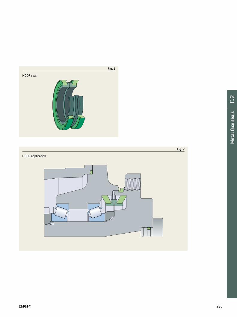
Fig. 1
HDDF seal
Fig. 2
HDDF application
285285
DE
F
G
H
I
Met
al f
ace
sea
lsC.2

Permissible operating conditions
Depending on their design, metal face seals
can withstand different amounts of internal
pressure. It should, however, generally be
maintained below 0,25 MPa (35 psi). Other
recommendations regarding operating con-
ditions for the metal face seals, like temper-
ature and speed, are provided in table 1.
The chemical resistance of the nitrile and
luoro rubber in general is dealt with in the
section Chemical resistance on page 37.
Contaminants
Metal face seals are often used in heavily
contaminated environments, where mud
packing in the cavity between the housing,
sealing rings and Belleville washers can
occur. Eventually, the mud packing can cause
the Belleville washers to be pushed out of
position, resulting in improper face loads or
mud being pumped past the Belleville
washers.
Contaminants can also cause abrasion to
the Belleville washers, which in turn causes
deteri or ation of the elastomer. To minimize
the risk of seal failure due to this deterioria-
tion, it is critical to select a proper Belleville
washer material for the application in
question.
Installing HDDF seals
General
Careful handling and installation of a metal
face seal is crucial to avoid cutting or tearing
of the elastomeric Belleville washers or
breaking the metal sealing rings, both which
can cause premature seal failure and imme-
diate leakage. It is also vital to keep the seal-
ing faces free of contaminants like dirt or lint.
Always carefully observe installation instruc-
tions provided on page 287.
Housing and seal preparation
All housing components contacting the
Belleville washers must be free of contami-
nants (oil, grease, dust, lint particles etc.)
when installing the seal. SKF recommends
using a non-petrol eum based solvent and a
clean, lint-free wipe to clean these compo-
nents prior to installation.
All seal parts must be handled with care
to avoid damage or scoring.
Table 1
Permissible operating conditions
Operating condition Recommended value
Temperature, max.Continuous operationNitrile rubber (NBR) –25 to +100 °C (–15 to +210 °F)Fluoro rubber (FKM) –10 to +190 °C (15 to 375 °F)
Circumferential speed, max.Continuous operation 1,8 m/s (350 ft/min)
Brief periods 3,8 m/s (750 ft/min)
Pressure, max.Continuous operation 0,25 MPa (35 psi)
Brief periods 0,35 MPa (50 psi)
286286
Axial shaft seals | Metal face seals

Installation procedure
1 Install the Belleville washers seated
against the inside shoulder of the metal
sealing rings († ig. 4a).
2 Carefully push each seal half (Belleville
washer and metal sealing ring) into the
housing until it is fully seated. Check that
the seal is not cocked and that the washers
are seated evenly at the bottom of the
housing bore. Improper seal installation
can result in uneven face loads around
the circumference of the seal faces,
causing scoring or the sealing rings to
separate and allow oil to leak.
3 Clean both metal sealing ring faces with
a lint-free wipe and apply a thin ilm of oil
Ensure that no oil is applied to any sur-
face but the sealing ring faces († ig. 4b)
4 Check that both housings are concentric
and in correct alignment The Belleville
washers must not unseat from the
bottom of the housing
5 Carefully bring the two housings
together, avoiding high impact that can
scratch or break the seal components
6 Finally, hold one half of the assembly
stationary while rotating the other half
at least ten complete revolutions
Fig. 3
Design features
Fig. 4
Installation procedure a
b
Belleville washers bore
sealing surface
metal sealing rings
shaft
seated seated
push
oil lightly
NOTE
This procedure enables the installer
to check that the housing and the
Belleville washers are aligned If the seal
assembly wobbles, it is necessary to
disassemble it and make sure that the
Belleville washers are properly seated
in the housing
287287
DE
F
G
H
I
Met
al f
ace
sea
lsC.2

Product tables
288288
Axial shaft seals | Metal face seals | HDDF – inch and metric dimensions
d1 1.688–8.688 in
Designation Lip mat- erial
Inch dimensions Operating width
Seal inside diameter
Bore depth
Recommended shoulder diameter
Under- cut
Sealing ring width
RadiusShaft
diameterBore diameter
d1 d1 D B1 d3 B D1 B2 b rmax. min. max. min. min. max. max.
– – in
16904 R 1.688 2.760 ±0.002 0.974 ±0.038 1.760 0.453 2.282 - - 0.846 0.037
18259 R 1.812 3.003 ±0.002 0.892 ±0.031 1.910 0.416 2.475 - - 0.790 0.042
21215 R 2.125 3.250 ±0.002 0.900 ±0.033 2.215 0.418 2.759 - - 0.812 0.045
25096 R 2.500 3.762 ±0.002 0.907 ±0.033 2.580 0.422 3.188 - - 0.840 0.042
27536 R 2.750 4.030 ±0.002 0.918 ±0.035 2.830 0.426 3.480 - - 0.810 0.042
30651 R 3.063 4.500 ±0.002 1.016 ±0.035 3.170 0.475 3.833 - - 0.912 0.042
35076 R 3.500 4.953 ±0.002 1.096 ±0.043 3.620 0.511 4.296 - - 0.962 0.035
38740 R 3.875 5.312 ±0.003 1.102 ±0.024 4.040 0.524 4.750 - - 1.002 0.042
38751 R 3.875 5.562 ±0.003 1.267 ±0.050 4.040 0.594 4.791 - - 1.110 0.051
43135 R 4.312 5.823 ±0.003 1.102 ±0.024 4.420 0.524 5.125 - - 1.002 0.042
43150 R 4.312 6.000 ±0.003 1.320 ±0.040 4.420 0.625 5.173 - - 1.090 0.051
46975 R 4.688 6.400 ±0.003 1.525 ±0.050 4.795 0.722 5.583 - - 1.254 0.047
50655 R 5.062 6.750 ±0.003 1.280 ±0.040 5.170 0.605 5.975 - - 1.150 0.057
54000 R 5.400 6.990 ±0.003 1.310 ±0.030 5.625 0.625 6.625 - - 1.182 0.057
56170 R 5.625 7.250 ±0.003 1.366 ±0.031 5.825 0.650 6.486 6.174 0.032 1.300 0.057
58775 R 5.875 7.641 ±0.003 1.510 ±0.031 6.000 0.724 6.868 6.548 0.056 1.490 0.073
63796 R 6.375 8.120 ±0.003 1.265 ±0.040 6.570 0.598 7.555 7.505 0.125 1.350 0.042
67560 R 6.750 8.620 ±0.004 1.375 ±0.030 6.920 0.656 7.750 - - 1.260 0.042
74310 R 7.438 9.400 ±0.004 1.656 ±0.040 7.540 0.793 8.431 - - 1.344 0.073
78020 R 7.800 10.000 ±0.004 1.750 ±0.050 7.940 0.835 8.910 - - 1.500 0.058
82540 R 8.250 10.062 ±0.004 1.560 ±0.040 8.358 0.745 9.280 9.220 0.071 1.562 0.058
86850 R 8.688 10.911 ±0.005 1.924 ±0.030 8.790 0.932 9.754 - - 1.642 0.058
B
B1B2
b
r
d1d3 D1D
3–5 mm (100–200 μin)

289289
DE
F
G
H
I
Met
al f
ace
sea
lsC.2
HDDF – inch and metric dimensions
d1 42,88–220,68 mm
Designation Lip mat- erial
Inch dimensions Operating width
Seal inside diameter
Bore depth
Recommended shoulder diameter
Under- cut
Sealing ring width
RadiusShaft
diameterBore diameter
d1 d1 D B1 d3 B D1 B2 b rmax. min. max. min. min. max. max.
– – mm
16904 R 42,88 70,10 ±0,06 24,74 ±0,97 44,70 11,51 57,96 - - 21,49 0,94
18259 R 46,03 76,28 ±0,06 22,66 ±0,79 48,51 10,57 62,87 - - 20,07 1,07
21215 R 53,98 82,55 ±0,06 22,86 ±0,84 56,26 10,62 70,08 - - 20,62 1,14
25096 R 63,50 95,56 ±0,06 23,04 ±0,84 65,53 10,72 80,98 - - 21,34 1,07
27536 R 69,85 102,36 ±0,06 23,32 ±0,89 71,88 10,82 88,39 - - 20,57 1,07
30651 R 77,80 114,30 ±0,06 25,81 ±0,89 80,52 12,07 97,36 - - 23,16 1,07
35076 R 88,90 125,81 ±0,06 27,84 ±1,09 91,95 12,98 109,12 - - 24,43 0,89
38740 R 98,43 134,92 ±0,08 27,99 ±0,61 102,62 13,31 120,65 - - 25,45 1,07
38751 R 98,43 141,27 ±0,08 32,18 ±1,27 102,62 15,09 121,69 - - 28,19 1,30
43135 R 109,52 147,90 ±0,08 27,99 ±0,61 112,27 13,31 130,18 - - 25,45 1,07
43150 R 109,52 152,40 ±0,08 33,53 ±1,02 112,27 15,88 131,39 - - 27,69 1,30
46975 R 119,08 162,56 ±0,08 38,74 ±1,27 121,79 18,34 141,81 - - 31,85 1,19
50655 R 128,57 171,45 ±0,08 32,51 ±1,02 131,32 15,37 151,77 - - 29,21 1,45
54000 R 137,16 177,55 ±0,08 33,27 ±0,76 142,88 15,88 168,28 - - 30,02 1,45
56170 R 142,88 184,15 ±0,08 34,70 ±0,79 147,96 16,51 164,74 156,82 0,81 33,02 1,45
58775 R 149,23 194,08 ±0,08 38,35 ±0,79 152,40 18,39 174,45 166,32 1,42 37,85 1,85
63796 R 161,93 206,25 ±0,08 32,13 ±1,02 166,88 15,19 191,90 190,63 3,18 34,29 1,07
67560 R 171,45 218,95 ±0,10 34,93 ±0,76 175,77 16,66 196,85 - - 32,00 1,07
74310 R 188,93 238,76 ±0,10 42,06 ±1,02 191,52 20,14 214,15 - - 34,14 1,85
78020 R 198,12 254,00 ±0,10 44,45 ±1,27 201,68 21,21 226,31 - - 38,10 1,47
82540 R 209,55 255,57 ±0,10 39,62 ±1,02 212,29 18,92 235,71 234,19 1,80 39,67 1,47
86850 R 220,68 277,14 ±0,13 48,87 ±0,76 223,27 23,67 247,75 - - 41,71 1,47

290290
Axial shaft seals | Metal face seals | HDDF – inch and metric dimensions
d1 9.312–29.000 in
Designation Lip mat- erial
Inch dimensions Operating width
Seal inside diameter
Bore depth
Recommended shoulder diameter
Under- cut
Sealing ring width
RadiusShaft
diameterBore diameter
d1 d1 D B1 d3 B D1 B2 b rmax. min. max. min. min. max. max.
– – in
93115 R 9.312 11.000 ±0.005 1.437 ±0.032 9.410 0.687 10.360 10.260 0.090 1.510 0.050
93125 R 9.312 11.625 ±0.005 1.754 ±0.050 9.410 0.837 10.750 - - 1.510 0.089
95620 R 9.562 11.859 ±0.005 1.949 ±0.069 9.660 0.925 10.703 - - 1.700 0.074
108710 R 10.875 12.969 ±0.005 1.540 ±0.050 11.060 0.730 12.100 12.000 0.143 1.670 0.043
116500 R 11.625 13.250 ±0.005 1.290 ±0.030 11.780 0.615 12.780 - - 1.210 0.045
124020 R 12.400 14.375 ±0.005 1.656 ±0.050 12.500 0.788 13.530 13.470 0.060 1.610 0.057
137570 R 13.750 15.817 ±0.005 1.875 ±0.032 13.910 0.906 14.985 - - 1.670 0.089
806715 R 14.750 16.695 ±0.005 1.875 ±0.032 14.950 0.906 15.863 - - 1.670 0.062
807115 V 14.750 16.695 ±0.005 1.875 ±0.032 14.950 0.906 15.863 - - 1.670 0.062
171025 R 17.125 19.240 ±0.006 1.531 ±0.053 17.280 0.724 18.400 18.300 0.140 1.659 0.043
191022 R 19.125 21.500 ±0.006 1.640 ±0.042 19.250 0.784 20.950 20.850 0.175 1.832 0.057
238020 R 23.875 26.875 ±0.006 2.125 ±0.040 24.280 1.018 25.550 - - 1.851 0.089
807199 V 23.875 26.875 ±0.006 2.125 ±0.040 24.280 1.018 25.550 - - 1.851 0.089
807149 V 29.000 32.000 ±0.006 2.125 ±0.040 29.512 1.028 30.672 - - 1.851 0.089
B
B1B2
b
r
d1d3 D1D
3–5 mm (100–200 μin)

291291
DE
F
G
H
I
Met
al f
ace
sea
lsC.2
HDDF – inch and metric dimensions
d1 232,52–736,60 mm
Designation Lip mat- erial
Inch dimensions Operating width
Seal inside diameter
Bore depth
Recommended shoulder diameter
Under- cut
Sealing ring width
RadiusShaft
diameterBore diameter
d1 d1 D B1 d3 B D1 B2 b rmax. min. max. min. min. max. max.
– – mm
93115 R 232,52 279,40 ±0,13 36,50 ±0,81 239,01 17,45 263,14 260,60 2,29 38,35 1,27
93125 R 236,52 295,28 ±0,13 44,55 ±1,27 239,01 21,26 273,05 - - 38,35 2,26
95620 R 242,87 301,22 ±0,13 49,50 ±1,75 245,36 23,50 271,86 - - 43,18 1,88
108710 R 276,23 329,41 ±0,13 39,12 ±1,27 280,92 18,54 307,34 304,80 3,63 42,42 1,09
116500 R 295,28 336,55 ±0,13 32,77 ±0,76 299,21 15,62 324,61 - - 30,73 1,14
124020 R 314,96 365,13 ±0,13 42,06 ±1,27 317,50 20,02 343,66 342,14 1,52 40,89 1,45
137570 R 349,25 401,75 ±0,13 47,63 ±0,81 353,31 23,01 380,62 - - 42,42 2,26
806715 R 374,65 424,05 ±0,13 47,63 ±0,81 379,73 23,01 402,92 - - 42,42 1,58
807115 V 374,65 424,05 ±0,13 47,63 ±0,81 379,73 23,01 402,92 - - 42,42 1,57
171025 R 434,98 488,70 ±0,15 38,89 ±1,35 438,91 18,39 467,36 464,82 3,56 42,14 1,09
191022 R 485,78 546,10 ±0,15 41,66 ±1,07 488,95 19,91 532,13 529,59 4,45 46,53 1,45
238020 R 606,43 682,63 ±0,15 53,98 ±1,02 616,71 25,86 648,97 - - 47,02 2,26
807199 V 606,43 682,63 ±0,15 53,98 ±1,02 616,71 25,86 648,97 - - 47,02 2,26
807149 V 736,60 812,80 ±0,15 53,98 ±1,02 749,60 26,11 779,07 - - 47,02 2,26

V-ring sealsC.3
292292
Axial shaft seals | V-ring seals

V-ring seals
› Cost-effective
› Versatile
ADMISSIBLE WORLDWIDE
293293
E
F
G
H
I
C.3
V-r
ing s
eals

General
V-ring seals (or V-rings) are unique all-rub-
ber seals for rotating shafts and are used in
an extremely wide range of applications. The
V-ring can be used alone to protect a wide
assort ment of bearing types from contami-
nants. They are also often used as secondary
seals to protect primary seals in highly con-
taminated environments.
V-rings are installed on shafts and their
thin, tapered lip seals against a counterface
perpendicular to the shaft († ig. 1a).
V-rings have an interference it on the shaft,
rotate with it and act as lingers († ig. 1b).
Angular misalignment of the shaft relative to
the counterface can be tolerated († ig. 1c).
V-rings provide reliable sealing even if the
shaft is out-of-round or
rotates eccen trically († ig. 1d). The amount
by which the shaft can be displaced axially is
governed by the permissible displacement of
the V-ring relative to its counterface.
V-rings are made entirely of elastomers
without fabric or metal reinforcement and
are therefore easy to install. They can be
stretched and, depending on size, pushed
over other com pon ents like langes, pulleys
or even housings. This is a very valuable
feature, especially when replacing a seal.
Features
A V-ring consists of a seal body, a lexible,
conical-shaped sealing lip and an integral,
resilient “hinge” († ig. 2). It is stretched and
installed directly on the shaft, where it is
held in place by the inherent tension of the
seal body. It rotates with the shaft and seals
axially against a stationary counterface.
The counterface can be the end face of a
bearing, a washer, stamping, bearing housing,
or even the metal case of a radial shaft seal.
The lexible sealing lip applies contact
pressure against the counterface that is
rela tively low but suficient enough to main-
tain the sealing function. The light contact
pressure even enables the seal to run dry in
some low-speed applications resulting in
insigniicant torque drag or heat build-up.
The contact pressure varies with the itted
width.
The lexible lip and hinge provide ade-
quate sealing even in applications with con-
siderable end play and shaft misalignment.
As a result of centrifugal force, the contact
pressure of the lip decreases with increasing
shaft speed. This means that friction losses
and heat are kept to a minimum, resulting
in improved wear resistance and extended
service life.
V-ring seals
Fig. 1
Installed V-ring seals
a b c d
a b c d
294294
Axial shaft seals | V-ring seals

Materials
V-rings are normally made of nitrile rubber
that features good chemical resistance,
resistance to wear and can be used in appli-
cations with temperatures ranging from –40
to +100 °C (–40 to +210 °F). For applications
with higher temperatures or where aggres-
sive media are present, V-rings made of
luoro rubber can be supplied. The permissi-
ble operating conditions for V-rings made of
nitrile or luoro rubber are listed in table 2
on page 299. In the product table under the
heading Lip code, the letters R and V are
used to identify nitrile rubber and luoro
rubber respectively.
Fig. 2
V-ring design
Sealing lip
Seal body
Hinge
� WARNING
At temperatures above 300 °C (570 °F),
all luoro rubber compounds give off
dangerous fumes.
For additional information, refer to
page 32.
295295
DE
F
G
H
I
V-r
ing s
eals
C.3

Standard designs
SKF offers ive standard V-ring designs:
• VA / VR1, the most common type of V-ring,
has a standard cross section and straight
back sideface. VA / VR1 is typically used to
protect bearing arrangements in gear-
boxes, electric motors and drives.
• VS / VR2, that has a standard low cross
section, tapered back face and wide body,
providing a irm hold on the shaft. VS /
VR2 is commonly used in agricultural and
automotive applications.
• VL / VR3, designed with a very compact
axial cross section. VL / VR3 is commonly
used in conined spaces to enhance laby-
rinth seals.
• VE / VR4, designed as secondary seals
for heavy-duty applications where the
primary seal has to be protected against
water and / or solid contaminants. The
design has the largest cross section of
any V-ring designs and also permits the
largest axial displacements. VE / VR4 is
available in the diameter range 300 to
2 010 mm (11.811 to 79.134 in).
• VRME / VR6, a heavy-duty, large diameter
V-ring for applications with large axial
displacements. VRME / VR6 can be located
axially and radially on the shaft using a
standard band clamp. VRME / VR6 is pri-
marily designed to protect high-speed
bearing arrangements in rolling mills,
paper-making and other large machine
applications. VRME / VR6 is available on a
made-to-order basis.
V-rings from SKF are available for the shaft
diameter ranges listed in table 1. If the shaft
diam eter lies in the appropriate range for
two V-rings, the larger V-ring, refering to
the Seal itted with, should always be chosen
(† ig. 9 on page 302). In addition, special
sizes and designs, including split versions,
can be made to order. Contact your SKF
sales representative for sizes outside the
standard range.
Main V-ring functions
V-rings are suitable for both grease and oil
lubricated applications. For sealing grease
lubricated bearing arrangements and pro-
tecting against contaminants, the V-ring
should be arranged outside the housing
cover or housing wall. Dust, water spray and
other contaminants can be excluded in this
position († ig. 3). The V-ring can also act as
a grease valve, where used grease or excess
new grease can escape between the coun-
terface and the sealing lip († ig. 4). The
installation of two opposing V-rings can be
used in applications where lubricant reten-
tion and contaminant exclusion are of equal
importance († ig. 5).
If V-rings are used to retain oil, they
should always be located axially on the shaft
on the lubricant side († ig. 6).
V-rings should not be submerged in the
application medium.
Table 1
Standard V-ring designs and size ranges
Design, globally outside North America VA VS VL VE VRME Design, North America VR1 VR2 VR3 VR4 VR6
– mm in mm in mm in mm in mm in
min. 2,7 0.106 4,5 0.177 105 4.134 300 11.811 300 11.811
max. 2 020 79.257 210 8.268 2 025 79.724 2 010 79.134 1 995 78.543
296296
Axial shaft seals | V-ring seals

Fig. 3
V-ring used as an excluder
Fig. 4
V-ring used as a grease valve
Fig. 5
Two opposing V-rings
Fig. 6
V-ring located axially
297297
DE
F
G
H
I
V-r
ing s
eals
C.3

Other V-ring functions
V-rings can also be used as secondary seals
(† ig. 7), for example where it is necessary
to protect the sealing lip and counterface of
the primary seal against contaminants or
corrosion . V-rings can also be used to
enhance the eficiency of labyrinth seals
(† ig. 8).
Fig. 7
V-ring used as a secondary seal
Fig. 8
V-rings in a labyrinth seal
298298
Axial shaft seals | V-ring seals

Sliding velocities
V-rings can operate under the conditions
listed in table 2. In the speed range 15 to
20 m/s (2 900 to 3 900 ft/min), the sealing
lip lifts from the counterface and the V-ring
only acts as a gap-type seal.
Table 2
Permissible operating conditions
Operating conditions Guideline values for V-rings of
nitrile rubber luoro rubber
Temperature –40 to +100 °C (–40 to +210 °F) –20 to +150 °C (–4 to +300 °F)
Circumferential speed
normal (1) up to 8 m/s (1 575 ft/min) up to 6,5 m/s (1 280 ft/min)
located axially (2) 8 to 12 m/s (1 575 to 2 360 ft/min) 6,5 to 10 m/s (1 280 to 1 970 ft/min)
axial and radial support (3) > 12 m/s (2 360 ft/min) > 10 m/s (1 970 ft/min)
Pressure acting on seal
static sealing or very low speed operation up to 0,03 MPa (4.35 psi) up to 0,03 MPa (4.35 psi)
1normal
2located axially1)
3axial and radial support1)
1) Support ring by customer
299299
DE
F
G
H
I
V-r
ing s
eals
C.3

Coaxiality and runout
The total tolerance for the deviation from
coaxiality and runout should not exceed the
guideline values provided in table 3.
Table 3
Coaxiality and runout tolerances
Shaft diameter Total tolerancenominal for coaxiality
deviation and runout
d1 Kd1over incl over incl max
mm inc mm in
V-rings, VA / VR1 and VS / VR2 designs
9,5 0.374 0,4 0.0169,5 19,5 0.374 0.768 0,6 0.02419,5 38 0.768 1.496 0,9 0.03438 68 1.496 2.677 1,1 0.043
68 105 2.677 4.134 1,4 0.055105 155 4.134 6.102 1,6 0.063155 210 6.102 8.628 1,9 0.075210 2 020 8.628 79.527 3,6 0.142
V-rings, VL / VR3 designs
135 630 5.315 24.803 1,5 0.059
V-rings, VE / VR4 designs
450 2 010 17.716 79.134 6 0.236
Kd1
300300
Axial shaft seals | V-ring seals

Misalignment
V-rings can tolerate misalignment between
the shaft and housing, i.e. deviations from
the perpendicularity between the shaft and
counterface of the housing. Guideline values
for the max imum permissible angular mis-
alignment are provided in diagram 1. These
values apply to the V-ring designs VA / VR1
and VS / VR2, provided they are supported
axially on the shaft.
The permissible misalignment values for
the very compact VL / VR3 design are appre-
ciably lower than those for the VA / VR1 and
VS / VR2 designs.
In applications where V-rings are not sup-
ported axially on the shaft, the maximum
value in the diagram should be reduced.
Counterface
A ine-turned counterface is adequate for
V-rings. The appropriate surface roughness
values vary depending on the circumferen-
tial speed († table 4 on page 302). SKF
recommends bufing all turned surfaces with
an emery cloth to remove any sharp peaks
arising from the turning operation. The sur-
face inish should be measured at approxi-
mately 90 degrees to the path of the groove
to obtain a true reading of the surface.
Counterface treatment
In the presence of grease, oil or dry lubri-
cants, no special counterface treatment is
required. Mild steel counterfaces that are
exposed to water or other corrosives should
be protected, for example by zinc- or
chromium-plating or treated with an
anti-corrosive spray.
Additional counterface information
Aluminium surfaces should be free of
scratch marks. Surface hardness should be
> 100 HB in abrasive applications. Die cast
aluminium can be used in the as-cast
condition.
Steel and cast iron surfaces should be free
of lead and sharp tool marks. Cold rolled
steel stampings can be used without
machining.
Plastic counterface materials are gener-
ally not acceptable due to poor heat
dissipation.
Stainless steel should not be used in
dry-running applications unless the speed
is below 1 m/s (200 ft/min).
Diagram 1
Maximum permissible misalignment for V-rings of the VA / VR1 and VS / VR2 designs
4,0
3,0
2,0
1,0
0
±α
0 100 200 300 400 500 600 700 800 900 1 000
Shaft diameter [mm (in.)]
Misalignment a, degrees
(3.937) (7.874) (11.811) (15.748) (19.685) (23.622) (27.559) (31.496) (35.433) (39.370)
301301
DE
F
G
H
I
V-r
ing s
eals
C.3

Product table sorting order
When searching for a suitable V-ring for a
given shaft diameter, e.g. 930 mm, irst
identify the possible shaft diameter ranges
(d1). In this case, there are three possible
ranges († ig. 9a). Then look for the appro-
priate dimensions D1, D and B1 that are
listed in ascending order († ig. 9b). Please
note that this sorting order concept results
in that the shaft diameter ranges do not
always come in ascending order, e.g. here
925–975 mm is listed before 920–965 mm.
Table 4
Recommended counterface surface inish
Circumferential speed Surface inish
m/s ft/min Ra µm Ra µin
> 10 > 1 969 0,4–0,8 16–32
5–10 984–1 969 0,8–1,6 32–64
1–5 199–984 1,6–2,0 64–80
< 1 < 199 2,0–2,5 80–100
The surface inish must not be lower than Ra 0,05 µm (2 µin).
Fig. 9
Dimensions
Lip code
Designation
Shaft diameter range
Seal inside dia -meter, free state
Seal seat width
Nominal seal width
Nominal seal height
Clearance Counterface Seal itted width
d1 d b1 b c D1 D B1
over incl.
max. min.mm – –310 315 304 32,5 65 30 d1 + 24 d1 + 115 50 ± 12 R 310 VE R
304 32,5 65 21 d1 + 24 d1 + 115 50 ± 12 R 310 VRME R315 320 309 32,5 65 30 d1 + 24 d1 + 115 50 ± 12 R 315 VE R
309 32,5 65 21 d1 + 24 d1 + 115 50 ± 12 R 315 VRME R320 325 314 32,5 65 30 d1 + 24 d1 + 115 50 ± 12 R 320 VE R
314 32,5 65 21 d1 + 24 d1 + 115 50 ± 12 R 320 VRME R325 330 319 32,5 65 30 d1 + 24 d1 + 115 50 ± 12 R 325 VE R
319 32,5 65 21 d1 + 24 d1 + 115 50 ± 12 R 325 VRME R330 335 323 32,5 65 30 d1 + 24 d1 + 115 50 ± 12 R 330 VE R
323 32,5 65 21 d1 + 24 d1 + 115 50 ± 12 R 330 VRME R335 365 315 6 10,5 6,5 d1 + 5 d1 + 20 8 ± 1,5 R 350 VL R
315 6 10,5 6,5 d1 + 5 d1 + 20 8 ± 1,5 V 350 VL V
315 14,3 25 15 d1 + 10 d1 + 45 20 ± 4 R 350 VA R
315 14,3 25 15 d1 + 10 d1 + 45 20 ± 4 V 350 VA V335 340 328 32,5 65 30 d1 + 24 d1 + 115 50 ± 12 R 335
328 32,5 65 21 d + 24 DE
V-r
ing s
eals
C.3
V-ring seals – metric dimensions, globally valid outside North American market
a
b
302302
Axial shaft seals | V-ring seals

Shaft requirements
Sharp edges, nicks and burrs on the shaft
must be avoided to prevent damage to the
V-ring during installation.
V-rings rotate with the shaft and only
require a moderate surface roughness value.
As a general guideline, the value should not
exceed Ra 6,3 µm (252 µin). When sealing
luids or exposed to ine, solid contaminants,
the V-ring requires a surface roughness
value of maximum Ra 3,2 µm (128 µin).
A V-ring is stretched when installed and
its all shaft diameters within the ranges
listed in the product tables.
Installing V-rings
V-rings are elastic and can be stretched and
pushed over other components, which facili-
tates the installation († ig. 10). When sev-
eral V-rings are to be installed, a simple tool
(† ig. 11) can be used to push the seals to
their position at a predetermined distance
from the counterface. V-rings can also be
cut and rejoined in the ield.
The general installation guidelines include
the following:
• Clean the V-ring, counterface and shaft.
• Make sure that the shaft is dry and free
from grease or oil, particularly when
installing a V-ring without axial support.
• Lubricate the lip of the V-ring with a thin
ilm of grease or silicone oil.
• In applications where friction must be
reduced to a minimum, the counterface
should be coated with a low-friction agent.
Do not apply grease to the lip.
• Check that the V-ring is installed with a
uniform stretch around the shaft.
Fig. 10
Installing a V-ring
Fig. 11
Installation tool
303303
DE
F
G
H
I
V-r
ing s
eals
C.3

Product tables
Dimensions Lip code
Designation
Shaft diameter range
Seal inside dia -meter, free state
Seal seat width
Nominal seal width
Nominal seal height
Clearance Counterface Seal itted width
d1 d b1 b c D1 D B1over incl. max. min.
mm – –
2,7 3,5 2,5 2,1 3 1,5 d1 + 1 d1 + 4 2,5 ± 0,3 R 3 VA R2,5 2,1 3 1,5 d1 + 1 d1 + 4 2,5 ± 0,3 V 3 VA V
3,5 4,5 3,2 2,4 3,7 2 d1 + 1 d1 + 6 3 ± 0,4 R 4 VA R3,2 2,4 3,7 2 d1 + 1 d1 + 6 3 ± 0,4 V 4 VA V
4,5 5,5 4 2,4 3,7 2 d1 + 1 d1 + 6 3 ± 0,4 R 5 VA R4 2,4 3,7 2 d1 + 1 d1 + 6 3 ± 0,4 V 5 VA V4 3,9 5,2 2 d1 + 1 d1 + 6 4,5 ± 0,4 R 5 VS R4 3,9 5,2 2 d1 + 1 d1 + 6 4,5 ± 0,4 V 5 VS V
5,5 6,5 5 2,4 3,7 2 d1 + 1 d1 + 6 3 ± 0,4 R 6 VA R5 2,4 3,7 2 d1 + 1 d1 + 6 3 ± 0,4 V 6 VA V5 3,9 5,2 2 d1 + 1 d1 + 6 4,5 ± 0,4 R 6 VS R5 3,9 5,2 2 d1 + 1 d1 + 6 4,5 ± 0,4 V 6 VS V
6,5 8 6 2,4 3,7 2 d1 + 1 d1 + 6 3 ± 0,4 R 7 VA R6 2,4 3,7 2 d1 + 1 d1 + 6 3 ± 0,4 V 7 VA V6 3,9 5,2 2 d1 + 1 d1 + 6 4,5 ± 0,4 R 7 VS R6 3,9 5,2 2 d1 + 1 d1 + 6 4,5 ± 0,4 V 7 VS V
8 9,5 7 2,4 3,7 2 d1 + 1 d1 + 6 3 ± 0,4 R 8 VA R7 2,4 3,7 2 d1 + 1 d1 + 6 3 ± 0,4 V 8 VA V7 3,9 5,2 2 d1 + 1 d1 + 6 4,5 ± 0,4 R 8 VS R7 3,9 5,2 2 d1 + 1 d1 + 6 4,5 ± 0,4 V 8 VS V
9,5 11,5 9 3,4 5,5 3 d1 + 1 d1 + 9 4,5 ± 0,6 R 10 VA R
9 3,4 5,5 3 d1 + 1 d1 + 9 4,5 ± 0,6 V 10 VA V9 5,6 7,7 3 d1 + 1 d1 + 9 6,7 ± 0,6 R 10 VS R9 5,6 7,7 3 d1 + 1 d1 + 9 6,7 ± 0,6 V 10 VS V
11,5 12,5 10,5 3,4 5,5 3 d1 + 1 d1 + 9 4,5 ± 0,6 R 12 VA R10,5 3,4 5,5 3 d1 + 1 d1 + 9 4,5 ± 0,6 V 12 VA V
11,5 13,5 10,5 5,6 7,7 3 d1 + 1 d1 + 9 6,7 ± 0,6 R 12 VS R10,5 5,6 7,7 3 d1 + 1 d1 + 9 6,7 ± 0,6 V 12 VS V11,7 3,4 5,5 3 d1 + 1 d1 + 9 4,5 ± 0,6 R 13 VA R11,7 3,4 5,5 3 d1 + 1 d1 + 9 4,5 ± 0,6 V 13 VA V
13,5 15,5 12,5 3,4 5,5 3 d1 + 1 d1 + 9 4,5 ± 0,6 R 14 VA R12,5 3,4 5,5 3 d1 + 1 d1 + 9 4,5 ± 0,6 V 14 VA V
13,5 15,5 12,5 5,6 7,7 3 d1 + 1 d1 + 9 6,7 ± 0,6 R 14 VS R12,5 5,6 7,7 3 d1 + 1 d1 + 9 6,7 ± 0,6 V 14 VS V
304304
b
b1
B1
d1 D
c
d D1
Axial shaft seals | V-ring seals – metric dimensions, globally valid outside North American market
d1 2,7–58 mm

Dimensions Lip code
Designation
Shaft diameter range
Seal inside dia -meter, free state
Seal seat width
Nominal seal width
Nominal seal height
Clearance Counterface Seal itted width
d1 d b1 b c D1 D B1over incl. max. min.
mm – –
15,5 17 14 3,4 5,5 3 d1 + 1 d1 + 9 4,5 ± 0,6 R 16 VA R14 3,4 5,5 3 d1 + 1 d1 + 9 4,5 ± 0,6 V 16 VA V
15,5 17,5 14 5,6 7,7 3 d1 + 1 d1 + 9 6,7 ± 0,6 R 16 VS R14 5,6 7,7 3 d1 + 1 d1 + 9 6,7 ± 0,6 V 16 VS V
17,5 19 16 3,4 5,5 3 d1 + 1 d1 + 9 4,5 ± 0,6 R 18 VA R16 3,4 5,5 3 d1 + 1 d1 + 9 4,5 ± 0,6 V 18 VA V16 5,6 7,7 3 d1 + 1 d1 + 9 6,7 ± 0,6 R 18 VS R16 5,6 7,7 3 d1 + 1 d1 + 9 6,7 ± 0,6 V 18 VS V
19 21 18 4,7 7,5 4 d1 + 2 d1 + 12 6 ± 0,8 R 20 VA R18 4,7 7,5 4 d1 + 2 d1 + 12 6 ± 0,8 V 20 VA V18 7,9 10,5 4 d1 + 2 d1 + 12 9 ± 0,8 R 20 VS R18 7,9 10,5 4 d1 + 2 d1 + 12 9 ± 0,8 V 20 VS V
21 24 20 4,7 7,5 4 d1 + 2 d1 + 12 6 ± 0,8 R 22 VA R20 4,7 7,5 4 d1 + 2 d1 + 12 6 ± 0,8 V 22 VA V20 7,9 10,5 4 d1 + 2 d1 + 12 9 ± 0,8 R 22 VS R20 7,9 10,5 4 d1 + 2 d1 + 12 9 ± 0,8 V 22 VS V
24 27 22 4,7 7,5 4 d1 + 2 d1 + 12 6 ± 0,8 R 25 VA R22 4,7 7,5 4 d1 + 2 d1 + 12 6 ± 0,8 V 25 VA V22 7,9 10,5 4 d1 + 2 d1 + 12 9 ± 0,8 R 25 VS R22 7,9 10,5 4 d1 + 2 d1 + 12 9 ± 0,8 V 25 VS V
27 29 25 4,7 7,5 4 d1 + 2 d1 + 12 6 ± 0,8 R 28 VA R25 4,7 7,5 4 d1 + 2 d1 + 12 6 ± 0,8 V 28 VA V25 7,9 10,5 4 d1 + 2 d1 + 12 9 ± 0,8 R 28 VS R25 7,9 10,5 4 d1 + 2 d1 + 12 9 ± 0,8 V 28 VS V
29 31 27 4,7 7,5 4 d1 + 2 d1 + 12 6 ± 0,8 R 30 VA R27 4,7 7,5 4 d1 + 2 d1 + 12 6 ± 0,8 V 30 VA V27 7,9 10,5 4 d1 + 2 d1 + 12 9 ± 0,8 R 30 VS R27 7,9 10,5 4 d1 + 2 d1 + 12 9 ± 0,8 V 30 VS V
31 33 29 4,7 7,5 4 d1 + 2 d1 + 12 6 ± 0,8 R 32 VA R29 4,7 7,5 4 d1 + 2 d1 + 12 6 ± 0,8 V 32 VA V29 7,9 10,5 4 d1 + 2 d1 + 12 9 ± 0,8 R 32 VS R29 7,9 10,5 4 d1 + 2 d1 + 12 9 ± 0,8 V 32 VS V
33 36 31 4,7 7,5 4 d1 + 2 d1 + 12 6 ± 0,8 R 35 VA R31 4,7 7,5 4 d1 + 2 d1 + 12 6 ± 0,8 V 35 VA V31 7,9 10,5 4 d1 + 2 d1 + 12 9 ± 0,8 R 35 VS R31 7,9 10,5 4 d1 + 2 d1 + 12 9 ± 0,8 V 35 VS V
36 38 34 4,7 7,5 4 d1 + 2 d1 + 12 6 ± 0,8 R 38 VA R34 4,7 7,5 4 d1 + 2 d1 + 12 6 ± 0,8 V 38 VA V34 7,9 10,5 4 d1 + 2 d1 + 12 9 ± 0,8 R 38 VS R34 7,9 10,5 4 d1 + 2 d1 + 12 9 ± 0,8 V 38 VS V
38 43 36 5,5 9 5 d1 + 2 d1 + 15 7 ± 1 R 40 VA R36 5,5 9 5 d1 + 2 d1 + 15 7 ± 1 V 40 VA V36 9,5 13 5 d1 + 2 d1 + 15 11 ± 1 R 40 VS R36 9,5 13 5 d1 + 2 d1 + 15 11 ± 1 V 40 VS V
43 48 40 5,5 9 5 d1 + 2 d1 + 15 7 ± 1 R 45 VA R40 5,5 9 5 d1 + 2 d1 + 15 7 ± 1 V 45 VA V40 9,5 13 5 d1 + 2 d1 + 15 11 ± 1 R 45 VS R40 9,5 13 5 d1 + 2 d1 + 15 11 ± 1 V 45 VS V
48 53 45 5,5 9 5 d1 + 2 d1 + 15 7 ± 1 R 50 VA R45 5,5 9 5 d1 + 2 d1 + 15 7 ± 1 V 50 VA V45 9,5 13 5 d1 + 2 d1 + 15 11 ± 1 R 50 VS R45 9,5 13 5 d1 + 2 d1 + 15 11 ± 1 V 50 VS V
53 58 49 5,5 9 5 d1 + 2 d1 + 15 7 ± 1 R 55 VA R49 5,5 9 5 d1 + 2 d1 + 15 7 ± 1 V 55 VA V
305305
DE
F
G
H
I
V-r
ing s
eals
C.3
V-ring seals – metric dimensions, globally valid outside North American market

Dimensions Lip code
Designation
Shaft diameter range
Seal inside dia -meter, free state
Seal seat width
Nominal seal width
Nominal seal height
Clearance Counterface Seal itted width
d1 d b1 b c D1 D B1over incl. max. min.
mm – –
49 9,5 13 5 d1 + 2 d1 + 15 11 ± 1 R 55 VS R49 9,5 13 5 d1 + 2 d1 + 15 11 ± 1 V 55 VS V
58 63 54 5,5 9 5 d1 + 2 d1 + 15 7 ± 1 R 60 VA R54 5,5 9 5 d1 + 2 d1 + 15 7 ± 1 V 60 VA V54 9,5 13 5 d1 + 2 d1 + 15 11 ± 1 R 60 VS R54 9,5 13 5 d1 + 2 d1 + 15 11 ± 1 V 60 VS V
63 68 58 5,5 9 5 d1 + 2 d1 + 15 7 ± 1 R 65 VA R58 5,5 9 5 d1 + 2 d1 + 15 7 ± 1 V 65 VA V58 9,5 13 5 d1 + 2 d1 + 15 11 ± 1 R 65 VS R58 9,5 13 5 d1 + 2 d1 + 15 11 ± 1 V 65 VS V
68 73 63 6,8 11 6 d1 + 3 d1 + 18 9 ± 1,2 R 70 VA R63 6,8 11 6 d1 + 3 d1 + 18 9 ± 1,2 V 70 VA V63 11,3 15,5 6 d1 + 3 d1 + 18 13,5 ± 1,2 R 70 VS R63 11,3 15,5 6 d1 + 3 d1 + 18 13,5 ± 1,2 V 70 VS V
73 78 67 6,8 11 6 d1 + 3 d1 + 18 9 ± 1,2 R 75 VA R67 6,8 11 6 d1 + 3 d1 + 18 13,5 ± 1,2 R 75 VS R67 11,3 15,5 6 d1 + 3 d1 + 18 13,5 ± 1,2 V 75 VS V
78 83 72 6,8 11 6 d1 + 3 d1 + 18 9 ± 1,2 R 80 VA R72 6,8 11 6 d1 + 3 d1 + 18 9 ± 1,2 V 80 VA V72 11,3 15,5 6 d1 + 3 d1 + 18 13,5 ± 1,2 R 80 VS R72 11,3 15,5 6 d1 + 3 d1 + 18 13,5 ± 1,2 V 80 VS V
83 88 76 6,8 11 6 d1 + 3 d1 + 18 9 ± 1,2 R 85 VA R76 6,8 11 6 d1 + 3 d1 + 18 9 ± 1,2 V 85 VA V76 11,3 15,5 6 d1 + 3 d1 + 18 13,5 ± 1,2 R 85 VS R76 11,3 15,5 6 d1 + 3 d1 + 18 13,5 ± 1,2 V 85 VS V
88 93 81 6,8 11 6 d1 + 3 d1 + 18 9 ± 1,2 R 90 VA R81 6,8 11 6 d1 + 3 d1 + 18 9 ± 1,2 V 90 VA V81 11,3 15,5 6 d1 + 3 d1 + 18 13,5 ± 1,2 R 90 VS R81 11,3 15,5 6 d1 + 3 d1 + 18 13,5 ± 1,2 V 90 VS V
93 98 85 6,8 11 6 d1 + 3 d1 + 18 9 ± 1,2 R 95 VA R85 6,8 11 6 d1 + 3 d1 + 18 9 ± 1,2 V 95 VA V85 11,3 15,5 6 d1 + 3 d1 + 18 13,5 ± 1,2 R 95 VS R85 11,3 15,5 6 d1 + 3 d1 + 18 13,5 ± 1,2 V 95 VS V
306306
b
b1
B1
d1 D
c
d D1
Axial shaft seals | V-ring seals – metric dimensions, globally valid outside North American market
d1 53–195 mm

Dimensions Lip code
Designation
Shaft diameter range
Seal inside dia -meter, free state
Seal seat width
Nominal seal width
Nominal seal height
Clearance Counterface Seal itted width
d1 d b1 b c D1 D B1over incl. max. min.
mm – –
98 105 90 6,8 11 6 d1 + 3 d1 + 18 9 ± 1,2 R 100 VA R90 6,8 11 6 d1 + 3 d1 + 18 9 ± 1,2 V 100 VA V90 11,3 15,5 6 d1 + 3 d1 + 18 13,5 ± 1,2 R 100 VS R90 11,3 15,5 6 d1 + 3 d1 + 18 13,5 ± 1,2 V 100 VS V
105 115 99 6 10,5 6,5 d1 + 5 d1 + 20 8 ± 1,5 R 110 VL R99 6 10,5 6,5 d1 + 5 d1 + 20 8 ± 1,5 V 110 VL V99 7,9 12,8 7 d1 + 4 d1 + 21 10,5 ± 1,5 R 110 VA R99 7,9 12,8 7 d1 + 4 d1 + 21 10,5 ± 1,5 V 110 VA V99 13,1 18 7 d1 + 4 d1 + 21 15,5 ± 1,5 R 110 VS R99 13,1 18 7 d1 + 4 d1 + 21 15,5 ± 1,5 V 110 VS V
115 125 108 6 10,5 6,5 d1 + 5 d1 + 20 8 ± 1,5 R 120 VL R108 6 10,5 6,5 d1 + 5 d1 + 20 8 ± 1,5 V 120 VL V108 7,9 12,8 7 d1 + 4 d1 + 21 10,5 ± 1,5 R 120 VA R108 7,9 12,8 7 d1 + 4 d1 + 21 10,5 ± 1,5 V 120 VA V108 13,1 18 7 d1 + 4 d1 + 21 15,5 ± 1,5 R 120 VS R108 13,1 18 7 d1 + 4 d1 + 21 15,5 ± 1,5 V 120 VS V
125 135 117 6 10,5 6,5 d1 + 5 d1 + 20 8 ± 1,5 R 130 VL R117 6 10,5 6,5 d1 + 5 d1 + 20 8 ± 1,5 V 130 VL V117 7,9 12,8 7 d1 + 4 d1 + 21 10,5 ± 1,5 R 130 VA R117 7,9 12,8 7 d1 + 4 d1 + 21 10,5 ± 1,5 V 130 VA V117 13,1 18 7 d1 + 4 d1 + 21 15,5 ± 1,5 R 130 VS R117 13,1 18 7 d1 + 4 d1 + 21 15,5 ± 1,5 V 130 VS V
135 145 126 6 10,5 6,5 d1 + 5 d1 + 20 8 ± 1,5 R 140 VL R126 6 10,5 6,5 d1 + 5 d1 + 20 8 ± 1,5 V 140 VL V126 7,9 12,8 7 d1 + 4 d1 + 21 10,5 ± 1,5 R 140 VA R126 7,9 12,8 7 d1 + 4 d1 + 21 10,5 ± 1,5 V 140 VA V126 13,1 18 7 d1 + 4 d1 + 21 15,5 ± 1,5 R 140 VS R126 13,1 18 7 d1 + 4 d1 + 21 15,5 ± 1,5 V 140 VS V
145 155 135 6 10,5 6,5 d1 + 5 d1 + 20 8 ± 1,5 R 150 VL R135 6 10,5 6,5 d1 + 5 d1 + 20 8 ± 1,5 V 150 VL V135 7,9 12,8 7 d1 + 4 d1 + 21 10,5 ± 1,5 R 150 VA R135 7,9 12,8 7 d1 + 4 d1 + 21 10,5 ± 1,5 V 150 VA V135 13,1 18 7 d1 + 4 d1 + 21 15,5 ± 1,5 R 150 VS R135 13,1 18 7 d1 + 4 d1 + 21 15,5 ± 1,5 V 150 VS V
155 165 144 6 10,5 6,5 d1 + 5 d1 + 20 8 ± 1,5 R 160 VL R144 6 10,5 6,5 d1 + 5 d1 + 20 8 ± 1,5 V 160 VL V144 9 14,5 8 d1 + 4 d1 + 24 12 ± 1,8 R 160 VA R144 9 14,5 8 d1 + 4 d1 + 24 12 ± 1,8 V 160 VA V144 15 20,5 8 d1 + 4 d1 + 24 18 ± 1,8 R 160 VS R144 15 20,5 8 d1 + 4 d1 + 24 18 ± 1,8 V 160 VS V
165 175 153 6 10,5 6,5 d1 + 5 d1 + 20 8 ± 1,5 R 170 VL R153 6 10,5 6,5 d1 + 5 d1 + 20 8 ± 1,5 V 170 VL V153 9 14,5 8 d1 + 4 d1 + 24 12 ± 1,8 R 170 VA R153 9 14,5 8 d1 + 4 d1 + 24 12 ± 1,8 V 170 VA V153 15 20,5 8 d1 + 4 d1 + 24 18 ± 1,8 R 170 VS R153 15 20,5 8 d1 + 4 d1 + 24 18 ± 1,8 V 170 VS V
175 185 162 6 10,5 6,5 d1 + 5 d1 + 20 8 ± 1,5 R 180 VL R162 6 10,5 6,5 d1 + 5 d1 + 20 8 ± 1,5 V 180 VL V162 9 14,5 8 d1 + 4 d1 + 24 12 ± 1,8 R 180 VA R162 9 14,5 8 d1 + 4 d1 + 24 12 ± 1,8 V 180 VA V162 15 20,5 8 d1 + 4 d1 + 24 18 ± 1,8 R 180 VS R162 15 20,5 8 d1 + 4 d1 + 24 18 ± 1,8 V 180 VS V
185 195 171 6 10,5 6,5 d1 + 5 d1 + 20 8 ± 1,5 R 190 VL R171 6 10,5 6,5 d1 + 5 d1 + 20 8 ± 1,5 V 190 VL V171 9 14,5 8 d1 + 4 d1 + 24 12 ± 1,8 R 190 VA R171 9 14,5 8 d1 + 4 d1 + 24 12 ± 1,8 V 190 VA V171 15 20,5 8 d1 + 4 d1 + 24 18 ± 1,8 R 190 VS R171 15 20,5 8 d1 + 4 d1 + 24 18 ± 1,8 V 190 VS V
307307
DE
F
G
H
I
V-r
ing s
eals
C.3
V-ring seals – metric dimensions, globally valid outside North American market

Dimensions Lip code
Designation
Shaft diameter range
Seal inside dia -meter, free state
Seal seat width
Nominal seal width
Nominal seal height
Clearance Counterface Seal itted width
d1 d b1 b c D1 D B1over incl. max. min.
mm – –
195 210 182 6 10,5 6,5 d1 + 5 d1 + 20 8 ± 1,5 R 200 VL R182 6 10,5 6,5 d1 + 5 d1 + 20 8 ± 1,5 V 200 VL V180 9 14,5 8 d1 + 4 d1 + 24 12 ± 1,8 R 199 VA R180 9 14,5 8 d1 + 4 d1 + 24 12 ± 1,8 V 199 VA V180 15 20,5 8 d1 + 4 d1 + 24 18 ± 1,8 R 199 VS R180 15 20,5 8 d1 + 4 d1 + 24 18 ± 1,8 V 199 VS V
190 210 180 14,3 25 15 d1 + 10 d1 + 45 20 ± 4 R 200 VA R180 14,3 25 15 d1 + 10 d1 + 45 20 ± 4 V 200 VA V
210 233 198 6 10,5 6,5 d1 + 5 d1 + 20 8 ± 1,5 R 220 VL R198 6 10,5 6,5 d1 + 5 d1 + 20 8 ± 1,5 V 220 VL V198 14,3 25 15 d1 + 10 d1 + 45 20 ± 4 R 220 VA R198 14,3 25 15 d1 + 10 d1 + 45 20 ± 4 V 220 VA V
233 260 225 6 10,5 6,5 d1 + 5 d1 + 20 8 ± 1,5 R 250 VL R225 6 10,5 6,5 d1 + 5 d1 + 20 8 ± 1,5 V 250 VL V
235 265 225 14,3 25 15 d1 + 10 d1 + 45 20 ± 4 R 250 VA R225 14,3 25 15 d1 + 10 d1 + 45 20 ± 4 V 250 VA V
260 285 247 6 10,5 6,5 d1 + 5 d1 + 20 8 ± 1,5 R 275 VL R247 6 10,5 6,5 d1 + 5 d1 + 20 8 ± 1,5 V 275 VL V
265 290 247 14,3 25 15 d1 + 10 d1 + 45 20 ± 4 R 275 VA R247 14,3 25 15 d1 + 10 d1 + 45 20 ± 4 V 275 VA V
285 310 270 6 10,5 6,5 d1 + 5 d1 + 20 8 ± 1,5 R 300 VL R270 6 10,5 6,5 d1 + 5 d1 + 20 8 ± 1,5 V 300 VL V
290 310 270 14,3 25 15 d1 + 10 d1 + 45 20 ± 4 R 300 VA R270 14,3 25 15 d1 + 10 d1 + 45 20 ± 4 V 300 VA V
300 305 294 32,5 65 30 d1 + 24 d1 + 115 50 ± 12 R 300 VE R294 32,5 65 21 d1 + 24 d1 + 115 50 ± 12 R 300 VRME R
305 310 299 32,5 65 30 d1 + 24 d1 + 115 50 ± 12 R 305 VE R299 32,5 65 21 d1 + 24 d1 + 115 50 ± 12 R 305 VRME R
310 335 292 6 10,5 6,5 d1 + 5 d1 + 20 8 ± 1,5 R 325 VL R292 6 10,5 6,5 d1 + 5 d1 + 20 8 ± 1,5 V 325 VL V
310 335 292 14,3 25 15 d1 + 10 d1 + 45 20 ± 4 R 325 VA R292 14,3 25 15 d1 + 10 d1 + 45 20 ± 4 V 325 VA V
308308
b
b1
B1
d1 D
c
d D1
Axial shaft seals | V-ring seals – metric dimensions, globally valid outside North American market
d1 195–400 mm

Dimensions Lip code
Designation
Shaft diameter range
Seal inside dia -meter, free state
Seal seat width
Nominal seal width
Nominal seal height
Clearance Counterface Seal itted width
d1 d b1 b c D1 D B1over incl. max. min.
mm – –
310 315 304 32,5 65 30 d1 + 24 d1 + 115 50 ± 12 R 310 VE R304 32,5 65 21 d1 + 24 d1 + 115 50 ± 12 R 310 VRME R
315 320 309 32,5 65 30 d1 + 24 d1 + 115 50 ± 12 R 315 VE R309 32,5 65 21 d1 + 24 d1 + 115 50 ± 12 R 315 VRME R
320 325 314 32,5 65 30 d1 + 24 d1 + 115 50 ± 12 R 320 VE R314 32,5 65 21 d1 + 24 d1 + 115 50 ± 12 R 320 VRME R
325 330 319 32,5 65 30 d1 + 24 d1 + 115 50 ± 12 R 325 VE R319 32,5 65 21 d1 + 24 d1 + 115 50 ± 12 R 325 VRME R
330 335 323 32,5 65 30 d1 + 24 d1 + 115 50 ± 12 R 330 VE R323 32,5 65 21 d1 + 24 d1 + 115 50 ± 12 R 330 VRME R
335 365 315 6 10,5 6,5 d1 + 5 d1 + 20 8 ± 1,5 R 350 VL R315 6 10,5 6,5 d1 + 5 d1 + 20 8 ± 1,5 V 350 VL V315 14,3 25 15 d1 + 10 d1 + 45 20 ± 4 R 350 VA R315 14,3 25 15 d1 + 10 d1 + 45 20 ± 4 V 350 VA V
335 340 328 32,5 65 30 d1 + 24 d1 + 115 50 ± 12 R 335 VE R328 32,5 65 21 d1 + 24 d1 + 115 50 ± 12 R 335 VRME R
340 345 333 32,5 65 30 d1 + 24 d1 + 115 50 ± 12 R 340 VE R328 32,5 65 21 d1 + 24 d1 + 115 50 ± 12 R 340 VRME R
345 350 338 32,5 65 30 d1 + 24 d1 + 115 50 ± 12 R 345 VE R338 32,5 65 21 d1 + 24 d1 + 115 50 ± 12 R 345 VRME R
350 355 343 32,5 65 30 d1 + 24 d1 + 115 50 ± 12 R 350 VE R343 32,5 65 21 d1 + 24 d1 + 115 50 ± 12 R 350 VRME R
355 360 347 32,5 65 30 d1 + 24 d1 + 115 50 ± 12 R 355 VE R347 32,5 65 21 d1 + 24 d1 + 115 50 ± 12 R 355 VRME R
360 365 352 32,5 65 30 d1 + 24 d1 + 115 50 ± 12 R 360 VE R357 32,5 65 21 d1 + 24 d1 + 115 50 ± 12 R 360 VRME R
365 385 337 6 10,5 6,5 d1 + 5 d1 + 20 8 ± 1,5 R 375 VL R337 6 10,5 6,5 d1 + 5 d1 + 20 8 ± 1,5 V 375 VL V
365 390 337 14,3 25 15 d1 + 10 d1 + 45 20 ± 4 R 375 VA R337 14,3 25 15 d1 + 10 d1 + 45 20 ± 4 V 375 VA V
365 370 357 32,5 65 30 d1 + 24 d1 + 115 50 ± 12 R 365 VE R
370 375 362 32,5 65 30 d1 + 24 d1 + 115 50 ± 12 R 370 VE R362 32,5 65 21 d1 + 24 d1 + 115 50 ± 12 R 370 VRME R
375 380 367 32,5 65 30 d1 + 24 d1 + 115 50 ± 12 R 375 VE R367 32,5 65 21 d1 + 24 d1 + 115 50 ± 12 R 375 VRME R
380 385 371 32,5 65 30 d1 + 24 d1 + 115 50 ± 12 R 380 VE R371 32,5 65 21 d1 + 24 d1 + 115 50 ± 12 R 380 VRME R
385 410 360 6 10,5 6,5 d1 + 5 d1 + 20 8 ± 1,5 R 400 VL R360 6 10,5 6,5 d1 + 5 d1 + 20 8 ± 1,5 V 400 VL V
390 430 360 14,3 25 15 d1 + 10 d1 + 45 20 ± 4 R 400 VA R360 14,3 25 15 d1 + 10 d1 + 45 20 ± 4 V 400 VA V
385 390 376 32,5 65 30 d1 + 24 d1 + 115 50 ± 12 R 385 VE R376 32,5 65 21 d1 + 24 d1 + 115 50 ± 12 R 385 VRME R
390 395 381 32,5 65 30 d1 + 24 d1 + 115 50 ± 12 R 390 VE R381 32,5 65 21 d1 + 24 d1 + 115 50 ± 12 R 390 VRME R
395 400 386 32,5 65 30 d1 + 24 d1 + 115 50 ± 12 R 395 VE R386 32,5 65 21 d1 + 24 d1 + 115 50 ± 12 R 395 VRME R
309309
DE
F
G
H
I
V-r
ing s
eals
C.3
V-ring seals – metric dimensions, globally valid outside North American market

Dimensions Lip code
Designation
Shaft diameter range
Seal inside dia -meter, free state
Seal seat width
Nominal seal width
Nominal seal height
Clearance Counterface Seal itted width
d1 d b1 b c D1 D B1over incl. max. min.
mm – –
400 405 391 32,5 65 30 d1 + 24 d1 + 115 50 ± 12 R 400 VE R391 32,5 65 21 d1 + 24 d1 + 115 50 ± 12 R 400 VRME R
405 410 396 32,5 65 30 d1 + 24 d1 + 115 50 ± 12 R 405 VE R396 32,5 65 21 d1 + 24 d1 + 115 50 ± 12 R 405 VRME R
410 415 401 32,5 65 30 d1 + 24 d1 + 115 50 ± 12 R 410 VE R401 32,5 65 21 d1 + 24 d1 + 115 50 ± 12 R 410 VRME R
415 420 405 32,5 65 30 d1 + 24 d1 + 115 50 ± 12 R 415 VE R405 32,5 65 21 d1 + 24 d1 + 115 50 ± 12 R 415 VRME R
420 425 410 32,5 65 30 d1 + 24 d1 + 115 50 ± 12 R 420 VE R410 32,5 65 21 d1 + 24 d1 + 115 50 ± 12 R 420 VRME R
425 430 415 32,5 65 30 d1 + 24 d1 + 115 50 ± 12 R 425 VE R415 32,5 65 21 d1 + 24 d1 + 115 50 ± 12 R 425 VRME R
410 440 382 6 10,5 6,5 d1 + 5 d1 + 20 8 ± 1,5 R 425 VL R382 6 10,5 6,5 d1 + 5 d1 + 20 8 ± 1,5 V 425 VL V
440 475 405 6 10,5 6,5 d1 + 5 d1 + 20 8 ± 1,5 R 450 VL R405 6 10,5 6,5 d1 + 5 d1 + 20 8 ± 1,5 V 450 VL V
430 480 405 14,3 25 15 d1 + 10 d1 + 45 20 ± 4 R 450 VA R405 14,3 25 15 d1 + 10 d1 + 45 20 ± 4 V 450 VA V
430 435 420 32,5 65 30 d1 + 24 d1 + 115 50 ± 12 R 430 VE R420 32,5 65 21 d1 + 24 d1 + 115 50 ± 12 R 430 VRME R
435 440 425 32,5 65 30 d1 + 24 d1 + 115 50 ± 12 R 435 VE R425 32,5 65 21 d1 + 24 d1 + 115 50 ± 12 R 435 VRME R
440 445 429 32,5 65 30 d1 + 24 d1 + 115 50 ± 12 R 440 VE R429 32,5 65 21 d1 + 24 d1 + 115 50 ± 12 R 440 VRME R
445 450 434 32,5 65 30 d1 + 24 d1 + 115 50 ± 12 R 445 VE R434 32,5 65 21 d1 + 24 d1 + 115 50 ± 12 R 445 VRME R
450 455 439 32,5 65 30 d1 + 24 d1 + 115 50 ± 12 R 450 VE R439 32,5 65 21 d1 + 24 d1 + 115 50 ± 12 R 450 VRME R
455 460 444 32,5 65 30 d1 + 24 d1 + 115 50 ± 12 R 455 VE R444 32,5 65 21 d1 + 24 d1 + 115 50 ± 12 R 455 VRME R
310310
b
b1
B1
d1 D
c
d D1
Axial shaft seals | V-ring seals – metric dimensions, globally valid outside North American market
d1 400–550 mm

Dimensions Lip code
Designation
Shaft diameter range
Seal inside dia -meter, free state
Seal seat width
Nominal seal width
Nominal seal height
Clearance Counterface Seal itted width
d1 d b1 b c D1 D B1over incl. max. min.
mm – –
460 465 448 32,5 65 30 d1 + 24 d1 + 115 50 ± 12 R 460 VE R448 32,5 65 21 d1 + 24 d1 + 115 50 ± 12 R 460 VRME R
465 470 453 32,5 65 30 d1 + 24 d1 + 115 50 ± 12 R 465 VE R453 32,5 65 21 d1 + 24 d1 + 115 50 ± 12 R 465 VRME R
470 475 458 32,5 65 30 d1 + 24 d1 + 115 50 ± 12 R 470 VE R458 32,5 65 21 d1 + 24 d1 + 115 50 ± 12 R 470 VRME R
475 480 463 32,5 65 30 d1 + 24 d1 + 115 50 ± 12 R 475 VE R463 32,5 65 21 d1 + 24 d1 + 115 50 ± 12 R 475 VRME R
475 510 450 6 10,5 6,5 d1 + 5 d1 + 20 8 ± 1,5 R 500 VL R450 6 10,5 6,5 d1 + 5 d1 + 20 8 ± 1,5 V 500 VL V
510 540 472 6 10,5 6,5 d1 + 5 d1 + 20 8 ± 1,5 R 525 VL R472 6 10,5 6,5 d1 + 5 d1 + 20 8 ± 1,5 V 525 VL V
480 530 450 14,3 25 15 d1 + 10 d1 + 45 20 ± 4 R 500 VA R450 14,3 25 15 d1 + 10 d1 + 45 20 ± 4 V 500 VA V
480 485 468 32,5 65 30 d1 + 24 d1 + 115 50 ± 12 R 480 VE R468 32,5 65 21 d1 + 24 d1 + 115 50 ± 12 R 480 VRME R
485 490 473 32,5 65 30 d1 + 24 d1 + 115 50 ± 12 R 485 VE R473 32,5 65 21 d1 + 24 d1 + 115 50 ± 12 R 485 VRME R
490 495 478 32,5 65 30 d1 + 24 d1 + 115 50 ± 12 R 490 VE R478 32,5 65 21 d1 + 24 d1 + 115 50 ± 12 R 490 VRME R
495 500 483 32,5 65 30 d1 + 24 d1 + 115 50 ± 12 R 495 VE R483 32,5 65 21 d1 + 24 d1 + 115 50 ± 12 R 495 VRME R
500 505 488 32,5 65 30 d1 + 24 d1 + 115 50 ± 12 R 500 VE R488 32,5 65 21 d1 + 24 d1 + 115 50 ± 12 R 500 VRME R
505 510 493 32,5 65 30 d1 + 24 d1 + 115 50 ± 12 R 505 VE R493 32,5 65 21 d1 + 24 d1 + 115 50 ± 12 R 505 VRME R
510 515 497 32,5 65 30 d1 + 24 d1 + 115 50 ± 12 R 510 VE R497 32,5 65 21 d1 + 24 d1 + 115 50 ± 12 R 510 VRME R
515 520 502 32,5 65 30 d1 + 24 d1 + 115 50 ± 12 R 515 VE R502 32,5 65 21 d1 + 24 d1 + 115 50 ± 12 R 515 VRME R
520 525 507 32,5 65 30 d1 + 24 d1 + 115 50 ± 12 R 520 VE R507 32,5 65 21 d1 + 24 d1 + 115 50 ± 12 R 520 VRME R
525 530 512 32,5 65 30 d1 + 24 d1 + 115 50 ± 12 R 525 VE R512 32,5 65 21 d1 + 24 d1 + 115 50 ± 12 R 525 VRME R
540 575 495 6 10,5 6,5 d1 + 5 d1 + 20 8 ± 1,5 R 550 VL R495 6 10,5 6,5 d1 + 5 d1 + 20 8 ± 1,5 V 550 VL V
530 580 495 14,3 25 15 d1 + 10 d1 + 45 20 ± 4 R 550 VA R495 14,3 25 15 d1 + 10 d1 + 45 20 ± 4 V 550 VA V
530 535 517 32,5 65 30 d1 + 24 d1 + 115 50 ± 12 R 530 VE R517 32,5 65 21 d1 + 24 d1 + 115 50 ± 12 R 530 VRME R
535 540 521 32,5 65 30 d1 + 24 d1 + 115 50 ± 12 R 535 VE R521 32,5 65 21 d1 + 24 d1 + 115 50 ± 12 R 535 VRME R
540 545 526 32,5 65 30 d1 + 24 d1 + 115 50 ± 12 R 540 VE R526 32,5 65 21 d1 + 24 d1 + 115 50 ± 12 R 540 VRME R
545 550 531 32,5 65 30 d1 + 24 d1 + 115 50 ± 12 R 545 VE R531 32,5 65 21 d1 + 24 d1 + 115 50 ± 12 R 545 VRME R
311311
DE
F
G
H
I
V-r
ing s
eals
C.3
V-ring seals – metric dimensions, globally valid outside North American market

Dimensions Lip code
Designation
Shaft diameter range
Seal inside dia -meter, free state
Seal seat width
Nominal seal width
Nominal seal height
Clearance Counterface Seal itted width
d1 d b1 b c D1 D B1over incl. max. min.
mm – –
550 555 536 32,5 65 30 d1 + 24 d1 + 115 50 ± 12 R 550 VE R536 32,5 65 21 d1 + 24 d1 + 115 50 ± 12 R 550 VRME R
555 560 541 32,5 65 30 d1 + 24 d1 + 115 50 ± 12 R 555 VE R541 32,5 65 21 d1 + 24 d1 + 115 50 ± 12 R 555 VRME R
560 565 546 32,5 65 30 d1 + 24 d1 + 115 50 ± 12 R 560 VE R546 32,5 65 21 d1 + 24 d1 + 115 50 ± 12 R 560 VRME R
565 570 550 32,5 65 30 d1 + 24 d1 + 115 50 ± 12 R 565 VE R550 32,5 65 21 d1 + 24 d1 + 115 50 ± 12 R 565 VRME R
570 575 555 32,5 65 30 d1 + 24 d1 + 115 50 ± 12 R 570 VE R555 32,5 65 21 d1 + 24 d1 + 115 50 ± 12 R 570 VRME R
575 580 560 32,5 65 30 d1 + 24 d1 + 115 50 ± 12 R 575 VE R560 32,5 65 21 d1 + 24 d1 + 115 50 ± 12 R 575 VRME R
575 625 540 6 10,5 6,5 d1 + 5 d1 + 20 8 ± 1,5 R 600 VL R540 6 10,5 6,5 d1 + 5 d1 + 20 8 ± 1,5 V 600 VL V
580 630 540 14,3 25 15 d1 + 10 d1 + 45 20 ± 4 R 600 VA R540 14,3 25 15 d1 + 10 d1 + 45 20 ± 4 V 600 VA V
580 585 565 32,5 65 30 d1 + 24 d1 + 115 50 ± 12 R 580 VE R565 32,5 65 21 d1 + 24 d1 + 115 50 ± 12 R 580 VRME R
585 590 570 32,5 65 30 d1 + 24 d1 + 115 50 ± 12 R 585 VE R570 32,5 65 21 d1 + 24 d1 + 115 50 ± 12 R 585 VRME R
590 600 575 32,5 65 30 d1 + 24 d1 + 115 50 ± 12 R 590 VE R575 32,5 65 21 d1 + 24 d1 + 115 50 ± 12 R 590 VRME R
600 610 582 32,5 65 30 d1 + 24 d1 + 115 50 ± 12 R 600 VE R582 32,5 65 21 d1 + 24 d1 + 115 50 ± 12 R 600 VRME R
610 620 592 32,5 65 30 d1 + 24 d1 + 115 50 ± 12 R 610 VE R592 32,5 65 21 d1 + 24 d1 + 115 50 ± 12 R 610 VRME R
620 630 602 32,5 65 30 d1 + 24 d1 + 115 50 ± 12 R 620 VE R602 32,5 65 21 d1 + 24 d1 + 115 50 ± 12 R 620 VRME R
615 675 600 6 10,5 6,5 d1 + 5 d1 + 20 8 ± 1,5 R 650 VL R600 6 10,5 6,5 d1 + 5 d1 + 20 8 ± 1,5 V 650 VL V
312312
b
b1
B1
d1 D
c
d D1
Axial shaft seals | V-ring seals – metric dimensions, globally valid outside North American market
d1 550–792 mm

Dimensions Lip code
Designation
Shaft diameter range
Seal inside dia -meter, free state
Seal seat width
Nominal seal width
Nominal seal height
Clearance Counterface Seal itted width
d1 d b1 b c D1 D B1over incl. max. min.
mm – –
630 665 600 14,3 25 15 d1 + 10 d1 + 45 20 ± 4 R 650 VA R600 14,3 25 15 d1 + 10 d1 + 45 20 ± 4 V 650 VA V
630 640 612 32,5 65 30 d1 + 24 d1 + 115 50 ± 12 R 630 VE R612 32,5 65 21 d1 + 24 d1 + 115 50 ± 12 R 630 VRME R
640 650 621 32,5 65 30 d1 + 24 d1 + 115 50 ± 12 R 640 VE R621 32,5 65 21 d1 + 24 d1 + 115 50 ± 12 R 640 VRME R
650 660 631 32,5 65 30 d1 + 24 d1 + 115 50 ± 12 R 650 VE R631 32,5 65 21 d1 + 24 d1 + 115 50 ± 12 R 650 VRME R
660 670 640 32,5 65 30 d1 + 24 d1 + 115 50 ± 12 R 660 VE R640 32,5 65 21 d1 + 24 d1 + 115 50 ± 12 R 660 VRME R
675 710 630 6 10,5 6,5 d1 + 5 d1 + 20 8 ± 1,5 R 700 VL R630 6 10,5 6,5 d1 + 5 d1 + 20 8 ± 1,5 V 700 VL V
665 705 630 14,3 25 15 d1 + 10 d1 + 45 20 ± 4 R 700 VA R630 14,3 25 15 d1 + 10 d1 + 45 20 ± 4 V 700 VA V
670 680 650 32,5 65 30 d1 + 24 d1 + 115 50 ± 12 R 670 VE R650 32,5 65 21 d1 + 24 d1 + 115 50 ± 12 R 670 VRME R
680 690 660 32,5 65 30 d1 + 24 d1 + 115 50 ± 12 R 680 VE R660 32,5 65 21 d1 + 24 d1 + 115 50 ± 12 R 680 VRME R
690 700 670 32,5 65 30 d1 + 24 d1 + 115 50 ± 12 R 690 VE R670 32,5 65 21 d1 + 24 d1 + 115 50 ± 12 R 690 VRME R
700 710 680 32,5 65 30 d1 + 24 d1 + 115 50 ± 12 R 700 VE R680 32,5 65 21 d1 + 24 d1 + 115 50 ± 12 R 700 VRME R
710 740 670 6 10,5 6,5 d1 + 5 d1 + 20 8 ± 1,5 R 725 VL R670 6 10,5 6,5 d1 + 5 d1 + 20 8 ± 1,5 V 725 VL V
705 745 670 14,3 25 15 d1 + 10 d1 + 45 20 ± 4 R 725 VA R670 14,3 25 15 d1 + 10 d1 + 45 20 ± 4 V 725 VA V
710 720 689 32,5 65 30 d1 + 24 d1 + 115 50 ± 12 R 710 VE R689 32,5 65 21 d1 + 24 d1 + 115 50 ± 12 R 710 VRME R
720 730 699 32,5 65 30 d1 + 24 d1 + 115 50 ± 12 R 720 VE R699 32,5 65 21 d1 + 24 d1 + 115 50 ± 12 R 720 VRME R
730 740 709 32,5 65 30 d1 + 24 d1 + 115 50 ± 12 R 730 VE R709 32,5 65 21 d1 + 24 d1 + 115 50 ± 12 R 730 VRME R
740 750 718 32,5 65 30 d1 + 24 d1 + 115 50 ± 12 R 740 VE R718 32,5 65 21 d1 + 24 d1 + 115 50 ± 12 R 740 VRME R
740 775 705 6 10,5 6,5 d1 + 5 d1 + 20 8 ± 1,5 R 750 VL R705 6 10,5 6,5 d1 + 5 d1 + 20 8 ± 1,5 V 750 VL V
745 785 705 14,3 25 15 d1 + 10 d1 + 45 20 ± 4 R 750 VA R705 14,3 25 15 d1 + 10 d1 + 45 20 ± 4 V 750 VA V
750 758 728 32,5 65 30 d1 + 24 d1 + 115 50 ± 12 R 750 VE R728 32,5 65 21 d1 + 24 d1 + 115 50 ± 12 R 750 VRME R
758 766 735 32,5 65 30 d1 + 24 d1 + 115 50 ± 12 R 760 VE R735 32,5 65 21 d1 + 24 d1 + 115 50 ± 12 R 760 VRME R
766 774 743 32,5 65 30 d1 + 24 d1 + 115 50 ± 12 R 770 VE R743 32,5 65 21 d1 + 24 d1 + 115 50 ± 12 R 770 VRME R
774 783 751 32,5 65 30 d1 + 24 d1 + 115 50 ± 12 R 780 VE R751 32,5 65 21 d1 + 24 d1 + 115 50 ± 12 R 780 VRME R
783 792 759 32,5 65 30 d1 + 24 d1 + 115 50 ± 12 R 790 VE R759 32,5 65 21 d1 + 24 d1 + 115 50 ± 12 R 790 VRME R
313313
DE
F
G
H
I
V-r
ing s
eals
C.3
V-ring seals – metric dimensions, globally valid outside North American market

Dimensions Lip code
Designation
Shaft diameter range
Seal inside dia -meter, free state
Seal seat width
Nominal seal width
Nominal seal height
Clearance Counterface Seal itted width
d1 d b1 b c D1 D B1over incl. max. min.
mm – –
775 825 745 6 10,5 6,5 d1 + 5 d1 + 20 8 ± 1,5 R 800 VL R745 6 10,5 6,5 d1 + 5 d1 + 20 8 ± 1,5 V 800 VL V
785 830 745 14,3 25 15 d1 + 10 d1 + 45 20 ± 4 R 800 VA R745 14,3 25 15 d1 + 10 d1 + 45 20 ± 4 V 800 VA V
792 801 768 32,5 65 30 d1 + 24 d1 + 115 50 ± 12 R 800 VE R768 32,5 65 21 d1 + 24 d1 + 115 50 ± 12 R 800 VRME R
801 810 777 32,5 65 30 d1 + 24 d1 + 115 50 ± 12 R 810 VE R777 32,5 65 21 d1 + 24 d1 + 115 50 ± 12 R 810 VRME R
810 821 786 32,5 65 30 d1 + 24 d1 + 115 50 ± 12 R 820 VE R786 32,5 65 21 d1 + 24 d1 + 115 50 ± 12 R 820 VRME R
821 831 796 32,5 65 30 d1 + 24 d1 + 115 50 ± 12 R 830 VE R796 32,5 65 21 d1 + 24 d1 + 115 50 ± 12 R 830 VRME R
825 875 785 6 10,5 6,5 d1 + 5 d1 + 20 8 ± 1,5 R 850 VL R785 6 10,5 6,5 d1 + 5 d1 + 20 8 ± 1,5 V 850 VL V
830 875 785 14,3 25 15 d1 + 10 d1 + 45 20 ± 4 R 850 VA R785 14,3 25 15 d1 + 10 d1 + 45 20 ± 4 V 850 VA V
831 841 805 32,5 65 30 d1 + 24 d1 + 115 50 ± 12 R 840 VE R805 32,5 65 21 d1 + 24 d1 + 115 50 ± 12 R 840 VRME R
841 851 814 32,5 65 30 d1 + 24 d1 + 115 50 ± 12 R 850 VE R814 32,5 65 21 d1 + 24 d1 + 115 50 ± 12 R 850 VRME R
851 861 824 32,5 65 30 d1 + 24 d1 + 115 50 ± 12 R 860 VE R824 32,5 65 21 d1 + 24 d1 + 115 50 ± 12 R 860 VRME R
861 871 833 32,5 65 30 d1 + 24 d1 + 115 50 ± 12 R 870 VE R833 32,5 65 21 d1 + 24 d1 + 115 50 ± 12 R 870 VRME R
871 882 843 32,5 65 30 d1 + 24 d1 + 115 50 ± 12 R 880 VE R843 32,5 65 21 d1 + 24 d1 + 115 50 ± 12 R 880 VRME R
875 925 825 6 10,5 6,5 d1 + 5 d1 + 20 8 ± 1,5 R 900 VL R825 6 10,5 6,5 d1 + 5 d1 + 20 8 ± 1,5 V 900 VL V
875 920 825 14,3 25 15 d1 + 10 d1 + 45 20 ± 4 R 900 VA R825 14,3 25 15 d1 + 10 d1 + 45 20 ± 4 V 900 VA V
314314
b
b1
B1
d1 D
c
d D1
Axial shaft seals | V-ring seals – metric dimensions, globally valid outside North American market
d1 775–1 105 mm

Dimensions Lip code
Designation
Shaft diameter range
Seal inside dia -meter, free state
Seal seat width
Nominal seal width
Nominal seal height
Clearance Counterface Seal itted width
d1 d b1 b c D1 D B1over incl. max. min.
mm – –
882 892 853 32,5 65 30 d1 + 24 d1 + 115 50 ± 12 R 890 VE R853 32,5 65 21 d1 + 24 d1 + 115 50 ± 12 R 890 VRME R
892 912 871 32,5 65 30 d1 + 24 d1 + 115 50 ± 12 R 900 VE R871 32,5 65 21 d1 + 24 d1 + 115 50 ± 12 R 900 VRME R
912 922 880 32,5 65 30 d1 + 24 d1 + 115 50 ± 12 R 920 VE R880 32,5 65 21 d1 + 24 d1 + 115 50 ± 12 R 920 VRME R
925 975 865 6 10,5 6,5 d1 + 5 d1 + 20 8 ± 1,5 R 950 VL R865 6 10,5 6,5 d1 + 5 d1 + 20 8 ± 1,5 V 950 VL V
920 965 865 14,3 25 15 d1 + 10 d1 + 45 20 ± 4 R 950 VA R865 14,3 25 15 d1 + 10 d1 + 45 20 ± 4 V 950 VA V
922 933 890 32,5 65 30 d1 + 24 d1 + 115 50 ± 12 R 930 VE R890 32,5 65 21 d1 + 24 d1 + 115 50 ± 12 R 930 VRME R
933 944 900 32,5 65 30 d1 + 24 d1 + 115 50 ± 12 R 940 VE R900 32,5 65 21 d1 + 24 d1 + 115 50 ± 12 R 940 VRME R
944 955 911 32,5 65 30 d1 + 24 d1 + 115 50 ± 12 R 950 VE R911 32,5 65 21 d1 + 24 d1 + 115 50 ± 12 R 950 VRME R
955 966 921 32,5 65 30 d1 + 24 d1 + 115 50 ± 12 R 960 VE R921 32,5 65 21 d1 + 24 d1 + 115 50 ± 12 R 960 VRME R
975 1 025 910 6 10,5 6,5 d1 + 5 d1 + 20 8 ± 1,5 R 1000 VL R910 6 10,5 6,5 d1 + 5 d1 + 20 8 ± 1,5 V 1000 VL V
965 1 015 910 14,3 25 15 d1 + 10 d1 + 45 20 ± 4 R 1000 VA R910 14,3 25 15 d1 + 10 d1 + 45 20 ± 4 V 1000 VA V
966 977 932 32,5 65 30 d1 + 24 d1 + 115 50 ± 12 R 970 VE R932 32,5 65 21 d1 + 24 d1 + 115 50 ± 12 R 970 VRME R
977 988 942 32,5 65 30 d1 + 24 d1 + 115 50 ± 12 R 980 VE R942 32,5 65 21 d1 + 24 d1 + 115 50 ± 12 R 980 VRME R
988 999 953 32,5 65 30 d1 + 24 d1 + 115 50 ± 12 R 990 VE R953 32,5 65 21 d1 + 24 d1 + 115 50 ± 12 R 990 VRME R
999 1 010 963 32,5 65 30 d1 + 24 d1 + 115 50 ± 12 R 1000 VE R963 32,5 65 21 d1 + 24 d1 + 115 50 ± 12 R 1000 VRME R
1 010 1 025 973 32,5 65 30 d1 + 24 d1 + 115 50 ± 12 R 1020 VE R973 32,5 65 21 d1 + 24 d1 + 115 50 ± 12 R 1020 VRME R
1 025 1 075 955 6 10,5 6,5 d1 + 5 d1 + 20 8 ± 1,5 R 1050 VL R955 6 10,5 6,5 d1 + 5 d1 + 20 8 ± 1,5 V 1050 VL V
1 015 1 065 955 14,3 25 15 d1 + 10 d1 + 45 20 ± 4 R 1050 VA R
1 025 1 045 990 32,5 65 30 d1 + 24 d1 + 115 50 ± 12 R 1040 VE R990 32,5 65 21 d1 + 24 d1 + 115 50 ± 12 R 1040 VRME R
1 045 1 065 1 008 32,5 65 30 d1 + 24 d1 + 115 50 ± 12 R 1060 VE R1 008 32,5 65 21 d1 + 24 d1 + 115 50 ± 12 R 1060 VRME R
1 075 1 125 1 000 6 10,5 6,5 d1 + 5 d1 + 20 8 ± 1,5 R 1100 VL R1 000 6 10,5 6,5 d1 + 5 d1 + 20 8 ± 1,5 V 1100 VL V
1 065 1 115 1 000 14,3 25 15 d1 + 10 d1 + 45 20 ± 4 R 1100 VA R
1 065 1 085 1 027 32,5 65 30 d1 + 24 d1 + 115 50 ± 12 R 1080 VE R1 027 32,5 65 21 d1 + 24 d1 + 115 50 ± 12 R 1080 VRME R
1 085 1 105 1 045 32,5 65 30 d1 + 24 d1 + 115 50 ± 12 R 1100 VE R1 045 32,5 65 21 d1 + 24 d1 + 115 50 ± 12 R 1100 VRME R
315315
DE
F
G
H
I
V-r
ing s
eals
C.3
V-ring seals – metric dimensions, globally valid outside North American market

Dimensions Lip code
Designation
Shaft diameter range
Seal inside dia -meter, free state
Seal seat width
Nominal seal width
Nominal seal height
Clearance Counterface Seal itted width
d1 d b1 b c D1 D B1over incl. max. min.
mm – –
1 105 1 125 1 065 32,5 65 30 d1 + 24 d1 + 115 50 ± 12 R 1120 VE R1 065 32,5 65 21 d1 + 24 d1 + 115 50 ± 12 R 1120 VRME R
1 125 1 175 1 045 6 10,5 6,5 d1 + 5 d1 + 20 8 ± 1,5 R 1150 VL R1 045 6 10,5 6,5 d1 + 5 d1 + 20 8 ± 1,5 V 1150 VL V
1 115 1 165 1 045 14,3 25 15 d1 + 10 d1 + 45 20 ± 4 R 1150 VA R
1 125 1 145 1 084 32,5 65 30 d1 + 24 d1 + 115 50 ± 12 R 1140 VE R1 084 32,5 65 21 d1 + 24 d1 + 115 50 ± 12 R 1140 VRME R
1 145 1 165 1 103 32,5 65 30 d1 + 24 d1 + 115 50 ± 12 R 1160 VE R1 103 32,5 65 21 d1 + 24 d1 + 115 50 ± 12 R 1160 VRME R
1 175 1 225 1 090 6 10,5 6,5 d1 + 5 d1 + 20 8 ± 1,5 R 1200 VL R1 090 6 10,5 6,5 d1 + 5 d1 + 20 8 ± 1,5 V 1200 VL V
1 165 1 215 1 090 14,3 25 15 d1 + 10 d1 + 45 20 ± 4 R 1200 VA R
1 165 1 185 1 121 32,5 65 30 d1 + 24 d1 + 115 50 ± 12 R 1180 VE R1 121 32,5 65 21 d1 + 24 d1 + 115 50 ± 12 R 1180 VRME R
1 185 1 205 1 139 32,5 65 30 d1 + 24 d1 + 115 50 ± 12 R 1200 VE R1 139 32,5 65 21 d1 + 24 d1 + 115 50 ± 12 R 1200 VRME R
1 205 1 225 1 157 32,5 65 30 d1 + 24 d1 + 115 50 ± 12 R 1220 VE R1 157 32,5 65 21 d1 + 24 d1 + 115 50 ± 12 R 1220 VRME R
1 225 1 275 1 135 6 10,5 6,5 d1 + 5 d1 + 20 8 ± 1,5 R 1250 VL R1 135 6 10,5 6,5 d1 + 5 d1 + 20 8 ± 1,5 V 1250 VL V
1 215 1 270 1 135 14,3 25 15 d1 + 10 d1 + 45 20 ± 4 R 1250 VA R
1 225 1 245 1 176 32,5 65 30 d1 + 24 d1 + 115 50 ± 12 R 1240 VE R1 176 32,5 65 21 d1 + 24 d1 + 115 50 ± 12 R 1240 VRME R
1 245 1 270 1 195 32,5 65 30 d1 + 24 d1 + 115 50 ± 12 R 1260 VE R1 195 32,5 65 21 d1 + 24 d1 + 115 50 ± 12 R 1260 VRME R
1 270 1 295 1 218 32,5 65 30 d1 + 24 d1 + 115 50 ± 12 R 1280 VE R1 218 32,5 65 21 d1 + 24 d1 + 115 50 ± 12 R 1280 VRME R
1 275 1 325 1 180 6 10,5 6,5 d1 + 5 d1 + 20 8 ± 1,5 R 1300 VL R 1 180 6 10,5 6,5 d1 + 5 d1 + 20 8 ± 1,5 V 1300 VL V
316316
b
b1
B1
d1 D
c
d D1
Axial shaft seals | V-ring seals – metric dimensions, globally valid outside North American market
d1 1 105–1 640 mm

Dimensions Lip code
Designation
Shaft diameter range
Seal inside dia -meter, free state
Seal seat width
Nominal seal width
Nominal seal height
Clearance Counterface Seal itted width
d1 d b1 b c D1 D B1over incl. max. min.
mm – –
1 270 1 320 1 180 14,3 25 15 d1 + 10 d1 + 45 20 ± 4 R 1300 VA R
1 295 1 315 1 240 32,5 65 30 d1 + 24 d1 + 115 50 ± 12 R 1300 VE R1 240 32,5 65 21 d1 + 24 d1 + 115 50 ± 12 R 1300 VRME R
1 315 1 340 1 259 32,5 65 30 d1 + 24 d1 + 115 50 ± 12 R 1325 VE R1 259 32,5 65 21 d1 + 24 d1 + 115 50 ± 12 R 1325 VRME R
1 325 1 375 1 225 6 10,5 6,5 d1 + 5 d1 + 20 8 ± 1,5 R 1350 VL R1 225 6 10,5 6,5 d1 + 5 d1 + 20 8 ± 1,5 V 1350 VL V
1 320 1 370 1 225 14,3 25 15 d1 + 10 d1 + 45 20 ± 4 R 1350 VA R
1 340 1 365 1 281 32,5 65 30 d1 + 24 d1 + 115 50 ± 12 R 1350 VE R 1 281 32,5 65 21 d1 + 24 d1 + 115 50 ± 12 R 1350 VRME R
1 365 1 390 1 305 32,5 65 30 d1 + 24 d1 + 115 50 ± 12 R 1375 VE R1 305 32,5 65 21 d1 + 24 d1 + 115 50 ± 12 R 1375 VRME R
1 375 1 425 1 270 6 10,5 6,5 d1 + 5 d1 + 20 8 ± 1,5 R 1400 VL R1 270 6 10,5 6,5 d1 + 5 d1 + 20 8 ± 1,5 V 1400 VL V
1 370 1 420 1 270 14,3 25 15 d1 + 10 d1 + 45 20 ± 4 R 1400 VA R 1 390 1 415 1 328 32,5 65 30 d1 + 24 d1 + 115 50 ± 12 R 1400 VE R
1 328 32,5 65 21 d1 + 24 d1 + 115 50 ± 12 R 1400 VRME R
1 415 1 440 1 350 32,5 65 30 d1 + 24 d1 + 115 50 ± 12 R 1425 VE R1 350 32,5 65 21 d1 + 24 d1 + 115 50 ± 12 R 1425 VRME R
1 425 1 475 1 315 6 10,5 6,5 d1 + 5 d1 + 20 8 ± 1,5 R 1450 VL R1 315 6 10,5 6,5 d1 + 5 d1 + 20 8 ± 1,5 V 1450 VL V
1 420 1 470 1 315 14,3 25 15 d1 + 10 d1 + 45 20 ± 4 R 1450 VA R
1 440 1 465 1 374 32,5 65 30 d1 + 24 d1 + 115 50 ± 12 R 1450 VE R1 374 32,5 65 21 d1 + 24 d1 + 115 50 ± 12 R 1450 VRME R
1 465 1 490 1 397 32,5 65 30 d1 + 24 d1 + 115 50 ± 12 R 1475 VE R1 397 32,5 65 21 d1 + 24 d1 + 115 50 ± 12 R 1475 VRME R
1 475 1 525 1 360 6 10,5 6,5 d1 + 5 d1 + 20 8 ± 1,5 R 1500 VL R1 360 6 10,5 6,5 d1 + 5 d1 + 20 8 ± 1,5 V 1500 VL V
1 470 1 520 1 360 14,3 25 15 d1 + 10 d1 + 45 20 ± 4 R 1500 VA R
1 490 1 515 1 419 32,5 65 30 d1 + 24 d1 + 115 50 ± 12 R 1500 VE R1 419 32,5 65 21 d1 + 24 d1 + 115 50 ± 12 R 1500 VRME R
1 515 1 540 1 443 32,5 65 30 d1 + 24 d1 + 115 50 ± 12 R 1525 VE R1 443 32,5 65 21 d1 + 24 d1 + 115 50 ± 12 R 1525 VRME R
1 525 1 575 1 405 6 10,5 6,5 d1 + 5 d1 + 20 8 ± 1,5 R 1550 VL R1 405 6 10,5 6,5 d1 + 5 d1 + 20 8 ± 1,5 V 1550 VL V
1 520 1 570 1 405 14,3 25 15 d1 + 10 d1 + 45 20 ± 4 R 1550 VA R
1 540 1 570 1 467 32,5 65 30 d1 + 24 d1 + 115 50 ± 12 R 1550 VE R1 467 32,5 65 21 d1 + 24 d1 + 115 50 ± 12 R 1550 VRME R
1 570 1 600 1 495 32,5 65 30 d1 + 24 d1 + 115 50 ± 12 R 1575 VE R1 495 32,5 65 21 d1 + 24 d1 + 115 50 ± 12 R 1575 VRME R
1 575 1 625 1 450 6 10,5 6,5 d1 + 5 d1 + 20 8 ± 1,5 R 1600 VL R1 450 6 10,5 6,5 d1 + 5 d1 + 20 8 ± 1,5 V 1600 VL V
1 570 1 620 1 450 14,3 25 15 d1 + 10 d1 + 45 20 ± 4 R 1600 VA R
1 600 1 640 1 524 32,5 65 30 d1 + 24 d1 + 115 50 ± 12 R 1600 VE R1 524 32,5 65 21 d1 + 24 d1 + 115 50 ± 12 R 1600 VRME R
317317
DE
F
G
H
I
V-r
ing s
eals
C.3
V-ring seals – metric dimensions, globally valid outside North American market

Dimensions Lip code
Designation
Shaft diameter range
Seal inside dia -meter, free state
Seal seat width
Nominal seal width
Nominal seal height
Clearance Counterface Seal itted width
d1 d b1 b c D1 D B1over incl. max. min.
mm – –
1 625 1 675 1 495 6 10,5 6,5 d1 + 5 d1 + 20 8 ± 1,5 R 1650 VL R1 495 6 10,5 6,5 d1 + 5 d1 + 20 8 ± 1,5 V 1650 VL V
1 620 1 670 1 495 14,3 25 15 d1 + 10 d1 + 45 20 ± 4 R 1650 VA R
1 640 1 680 1 559 32,5 65 30 d1 + 24 d1 + 115 50 ± 12 R 1650 VE R1 559 32,5 65 21 d1 + 24 d1 + 115 50 ± 12 R 1650 VRME R
1 675 1 725 1 540 6 10,5 6,5 d1 + 5 d1 + 20 8 ± 1,5 R 1700 VL R1 540 6 10,5 6,5 d1 + 5 d1 + 20 8 ± 1,5 V 1700 VL V
1 670 1 720 1 540 14,3 25 15 d1 + 10 d1 + 45 20 ± 4 R 1700 VA R
1 720 1 720 1 596 32,5 65 30 d1 + 24 d1 + 115 50 ± 12 R 1700 VE R1 596 32,5 65 21 d1 + 24 d1 + 115 50 ± 12 R 1700 VRME R
1 725 1 775 1 585 6 10,5 6,5 d1 + 5 d1 + 20 8 ± 1,5 R 1750 VL R1 585 6 10,5 6,5 d1 + 5 d1 + 20 8 ± 1,5 V 1750 VL V
1 720 1 770 1 585 14,3 25 15 d1 + 10 d1 + 45 20 ± 4 R 1750 VA R
1 720 1 765 1 632 32,5 65 30 d1 + 24 d1 + 115 50 ± 12 R 1750 VE R1 632 32,5 65 21 d1 + 24 d1 + 115 50 ± 12 R 1750 VRME R
1 765 1 810 1 671 32,5 65 30 d1 + 24 d1 + 115 50 ± 12 R 1800 VE R1 671 32,5 65 21 d1 + 24 d1 + 115 50 ± 12 R 1800 VRME R
1 775 1 825 1 630 6 10,5 6,5 d1 + 5 d1 + 20 8 ± 1,5 R 1800 VL R1 630 6 10,5 6,5 d1 + 5 d1 + 20 8 ± 1,5 V 1800 VL V
1 770 1 820 1 630 14,3 25 15 d1 + 10 d1 + 45 20 ± 4 R 1800 VA R
1 810 1 855 1 714 32,5 65 30 d1 + 24 d1 + 115 50 ± 12 R 1850 VE R1 714 32,5 65 21 d1 + 24 d1 + 115 50 ± 12 R 1850 VRME R
1 825 1 875 1 675 6 10,5 6,5 d1 + 5 d1 + 20 8 ± 1,5 R 1850 VL R1 675 6 10,5 6,5 d1 + 5 d1 + 20 8 ± 1,5 V 1850 VL V
1 820 1 870 1 675 14,3 25 15 d1 + 10 d1 + 45 20 ± 4 R 1850 VA R
1 855 1 905 1 753 32,5 65 30 d1 + 24 d1 + 115 50 ± 12 R 1900 VE R1 753 32,5 65 21 d1 + 24 d1 + 115 50 ± 12 R 1900 VRME R
1 875 1 925 1 720 6 10,5 6,5 d1 + 5 d1 + 20 8 ± 1,5 R 1900 VL R1 720 6 10,5 6,5 d1 + 5 d1 + 20 8 ± 1,5 V 1900 VL V
318318
b
b1
B1
d1 D
c
d D1
Axial shaft seals | V-ring seals – metric dimensions, globally valid outside North American market
d1 1 625–2 020 mm
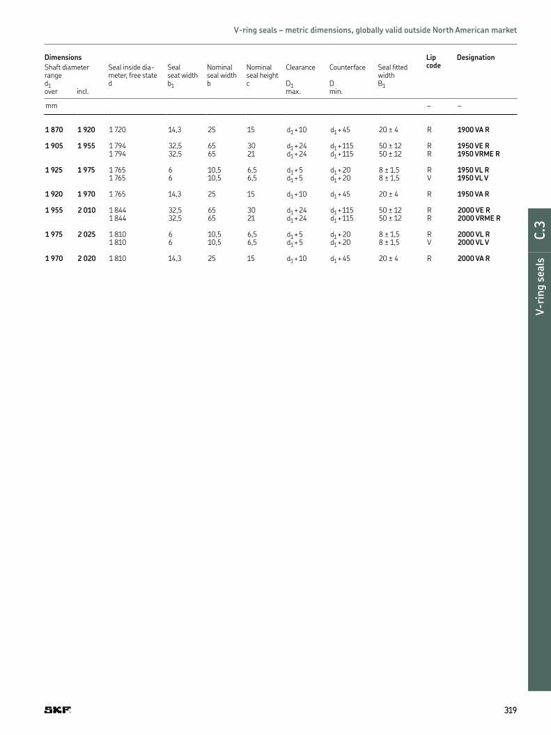
Dimensions Lip code
Designation
Shaft diameter range
Seal inside dia -meter, free state
Seal seat width
Nominal seal width
Nominal seal height
Clearance Counterface Seal itted width
d1 d b1 b c D1 D B1over incl. max. min.
mm – –
1 870 1 920 1 720 14,3 25 15 d1 + 10 d1 + 45 20 ± 4 R 1900 VA R
1 905 1 955 1 794 32,5 65 30 d1 + 24 d1 + 115 50 ± 12 R 1950 VE R1 794 32,5 65 21 d1 + 24 d1 + 115 50 ± 12 R 1950 VRME R
1 925 1 975 1 765 6 10,5 6,5 d1 + 5 d1 + 20 8 ± 1,5 R 1950 VL R1 765 6 10,5 6,5 d1 + 5 d1 + 20 8 ± 1,5 V 1950 VL V
1 920 1 970 1 765 14,3 25 15 d1 + 10 d1 + 45 20 ± 4 R 1950 VA R
1 955 2 010 1 844 32,5 65 30 d1 + 24 d1 + 115 50 ± 12 R 2000 VE R1 844 32,5 65 21 d1 + 24 d1 + 115 50 ± 12 R 2000 VRME R
1 975 2 025 1 810 6 10,5 6,5 d1 + 5 d1 + 20 8 ± 1,5 R 2000 VL R1 810 6 10,5 6,5 d1 + 5 d1 + 20 8 ± 1,5 V 2000 VL V
1 970 2 020 1 810 14,3 25 15 d1 + 10 d1 + 45 20 ± 4 R 2000 VA R
319319
DE
F
G
H
I
V-r
ing s
eals
C.3
V-ring seals – metric dimensions, globally valid outside North American market

Dimensions Lip code
Designation
Shaft diameter range
Seal inside dia -meter, free state
Nominal seal height
Seal seat width
Nominal seal width
Clearance Counterface Seal itted width
d1 d c b1 b D1 D B1over incl. max. min.
in – –
0.11 0.14 0.10 0.06 0.08 0.12 0.04 0.16 0.10 ± 0.012 R 3 VA R0.10 0.06 0.08 0.12 0.04 0.16 0.10 ± 0.012 V 3 VA V
0.14 0.18 0.13 0.08 0.09 0.15 0.04 0.24 0.12 ± 0.016 R 4 VA R0.13 0.08 0.09 0.15 0.04 0.24 0.12 ± 0.016 V 4 VA V
0.18 0.22 0.16 0.08 0.09 0.15 0.04 0.24 0.12 ± 0.016 R 5 VA R0.16 0.08 0.09 0.15 0.04 0.24 0.12 ± 0.016 V 5 VA V0.16 0.08 0.15 0.20 0.04 0.24 0.18 ± 0.016 R 5 VS R0.16 0.08 0.15 0.20 0.04 0.24 0.18 ± 0.016 V 5 VS V
0.22 0.26 0.20 0.08 0.09 0.15 0.04 0.24 0.12 ± 0.016 R 6 VA R0.20 0.08 0.09 0.15 0.04 0.24 0.12 ± 0.016 V 6 VA V0.20 0.08 0.15 0.20 0.04 0.24 0.18 ± 0.016 R 6 VS R0.20 0.08 0.15 0.20 0.04 0.24 0.18 ± 0.016 V 6 VS V
0.26 0.31 0.24 0.08 0.09 0.15 0.04 0.24 0.12 ± 0.016 R 7 VA R0.24 0.08 0.09 0.15 0.04 0.24 0.12 ± 0.016 V 7 VA V0.24 0.08 0.15 0.20 0.04 0.24 0.18 ± 0.016 R 7 VS R0.24 0.08 0.15 0.20 0.04 0.24 0.18 ± 0.016 V 7 VS V
0.31 0.37 0.28 0.08 0.09 0.15 0.04 0.24 0.12 ± 0.016 R 8 VA R0.28 0.08 0.09 0.15 0.04 0.24 0.12 ± 0.016 V 8 VA V0.28 0.08 0.15 0.20 0.04 0.24 0.18 ± 0.016 R 8 VS R0.28 0.08 0.15 0.20 0.04 0.24 0.18 ± 0.016 V 8 VS V
0.37 0.45 0.35 0.12 0.13 0.22 0.04 0.35 0.18 ± 0.02 R 10 VA R0.35 0.12 0.13 0.22 0.04 0.35 0.18 ± 0.02 V 10 VA V0.35 0.12 0.22 0.30 0.04 0.35 0.26 ± 0.02 R 10 VS R0.35 0.12 0.22 0.30 0.04 0.35 0.26 ± 0.02 V 10 VS V
0.45 0.49 0.41 0.12 0.13 0.22 0.04 0.35 0.18 ± 0.02 R 12 VA R0.41 0.12 0.13 0.22 0.04 0.35 0.18 ± 0.02 V 12 VA V
0.45 0.53 0.41 0.12 0.22 0.30 0.04 0.35 0.26 ± 0.02 R 12 VS R0.41 0.12 0.22 0.30 0.04 0.35 0.26 ± 0.02 V 12 VS V
0.49 0.53 0.46 0.12 0.13 0.22 0.04 0.35 0.18 ± 0.02 R 13 VA R0.46 0.12 0.13 0.22 0.04 0.35 0.18 ± 0.02 V 13 VA V
0.53 0.61 0.49 0.12 0.13 0.22 0.04 0.35 0.18 ± 0.02 R 14 VA R0.49 0.12 0.13 0.22 0.04 0.35 0.18 ± 0.02 V 14 VA V
0.53 0.61 0.49 0.12 0.22 0.30 0.04 0.35 0.26 ± 0.02 R 14 VS R0.49 0.12 0.22 0.30 0.04 0.35 0.26 ± 0.02 V 14 VS V
320320
b
b1
B1
d1 D
c
d D1
Axial shaft seals | V-ring seals – inch dimensions, globally valid outside North American market
d1 0.11–2.28 in

Dimensions Lip code
Designation
Shaft diameter range
Seal inside dia -meter, free state
Nominal seal height
Seal seat width
Nominal seal width
Clearance Counterface Seal itted width
d1 d c b1 b D1 D B1over incl. max. min.
in – –
0.61 0.67 0.55 0.12 0.13 0.22 0.04 0.35 0.18 ± 0.02 R 16 VA R0.55 0.12 0.13 0.22 0.04 0.35 0.18 ± 0.02 V 16 VA V
0.61 0.69 0.55 0.12 0.22 0.30 0.04 0.35 0.26 ± 0.02 R 16 VS R0.55 0.12 0.22 0.30 0.04 0.35 0.26 ± 0.02 V 16 VS V
0.69 0.75 0.63 0.12 0.13 0.22 0.04 0.35 0.18 ± 0.02 R 18 VA R0.63 0.12 0.13 0.22 0.04 0.35 0.18 ± 0.02 V 18 VA V0.63 0.12 0.22 0.30 0.04 0.35 0.26 ± 0.02 R 18 VS R0.63 0.12 0.22 0.30 0.04 0.35 0.26 ± 0.02 V 18 VS V
0.75 0.83 0.71 0.16 0.19 0.30 0.08 0.47 0.24 ± 0.03 R 20 VA R0.71 0.16 0.19 0.30 0.08 0.47 0.24 ± 0.03 V 20 VA V0.71 0.16 0.31 0.41 0.08 0.47 0.35 ± 0.03 R 20 VS R0.71 0.16 0.31 0.41 0.08 0.47 0.35 ± 0.03 V 20 VS V
0.83 0.94 0.79 0.16 0.19 0.30 0.08 0.47 0.24 ± 0.03 R 22 VA R0.79 0.16 0.19 0.30 0.08 0.47 0.24 ± 0.03 V 22 VA V0.79 0.16 0.31 0.41 0.08 0.47 0.35 ± 0.03 R 22 VS R0.79 0.16 0.31 0.41 0.08 0.47 0.35 ± 0.03 V 22 VS V
0.94 1.06 0.87 0.16 0.19 0.30 0.08 0.47 0.24 ± 0.03 R 25 VA R0.87 0.16 0.19 0.30 0.08 0.47 0.24 ± 0.03 V 25 VA V0.87 0.16 0.31 0.41 0.08 0.47 0.35 ± 0.03 R 25 VS R0.87 0.16 0.31 0.41 0.08 0.47 0.35 ± 0.03 V 25 VS V
1.06 1.14 0.98 0.16 0.19 0.30 0.08 0.47 0.24 ± 0.03 R 28 VA R0.98 0.16 0.19 0.30 0.08 0.47 0.24 ± 0.03 V 28 VA V0.98 0.16 0.31 0.41 0.08 0.47 0.35 ± 0.03 R 28 VS R0.98 0.16 0.31 0.41 0.08 0.47 0.35 ± 0.03 V 28 VS V
1.14 1.22 1.06 0.16 0.19 0.30 0.08 0.47 0.24 ± 0.03 R 30 VA R1.06 0.16 0.19 0.30 0.08 0.47 0.24 ± 0.03 V 30 VA V1.06 0.16 0.31 0.41 0.08 0.47 0.35 ± 0.03 R 30 VS R1.06 0.16 0.31 0.41 0.08 0.47 0.35 ± 0.03 V 30 VS V
1.22 1.30 1.14 0.16 0.19 0.30 0.08 0.47 0.24 ± 0.03 R 32 VA R1.14 0.16 0.19 0.30 0.08 0.47 0.24 ± 0.03 V 32 VA V1.14 0.16 0.31 0.41 0.08 0.47 0.35 ± 0.03 R 32 VS R1.14 0.16 0.31 0.41 0.08 0.47 0.35 ± 0.03 V 32 VS V
1.30 1.42 1.22 0.16 0.19 0.30 0.08 0.47 0.24 ± 0.03 R 35 VA R1.22 0.16 0.19 0.30 0.08 0.47 0.24 ± 0.03 V 35 VA V1.22 0.16 0.31 0.41 0.08 0.47 0.35 ± 0.03 R 35 VS R1.22 0.16 0.31 0.41 0.08 0.47 0.35 ± 0.03 V 35 VS V
1.42 1.50 1.34 0.16 0.19 0.30 0.08 0.47 0.24 ± 0.03 R 38 VA R1.34 0.16 0.19 0.30 0.08 0.47 0.24 ± 0.03 V 38 VA V1.34 0.16 0.31 0.41 0.08 0.47 0.35 ± 0.03 R 38 VS R1.34 0.16 0.31 0.41 0.08 0.47 0.35 ± 0.03 V 38 VS V
1.50 1.69 1.42 0.20 0.22 0.35 0.08 0.59 0.28 ± 0.04 R 40 VA R1.42 0.20 0.22 0.35 0.08 0.59 0.28 ± 0.04 V 40 VA V1.42 0.20 0.37 0.51 0.08 0.59 0.43 ± 0.04 R 40 VS R1.42 0.20 0.37 0.51 0.08 0.59 0.43 ± 0.04 V 40 VS V
1.69 1.89 1.57 0.20 0.22 0.35 0.08 0.59 0.28 ± 0.04 R 45 VA R1.57 0.20 0.22 0.35 0.08 0.59 0.28 ± 0.04 V 45 VA V1.57 0.20 0.37 0.51 0.08 0.59 0.43 ± 0.04 R 45 VS R1.57 0.20 0.37 0.51 0.08 0.59 0.43 ± 0.04 V 45 VS V
1.89 2.09 1.77 0.20 0.22 0.35 0.08 0.59 0.28 ± 0.04 R 50 VA R1.77 0.20 0.22 0.35 0.08 0.59 0.28 ± 0.04 V 50 VA V1.77 0.20 0.37 0.51 0.08 0.59 0.43 ± 0.04 R 50 VS R1.77 0.20 0.37 0.51 0.08 0.59 0.43 ± 0.04 V 50 VS V
2.09 2.28 1.93 0.20 0.22 0.35 0.08 0.59 0.28 ± 0.04 R 55 VA R1.93 0.20 0.22 0.35 0.08 0.59 0.28 ± 0.04 V 55 VA V1.93 0.20 0.37 0.51 0.08 0.59 0.43 ± 0.04 R 55 VS R1.93 0.20 0.37 0.51 0.08 0.59 0.43 ± 0.04 V 55 VS V
321321
DE
F
G
H
I
V-r
ing s
eals
C.3
V-ring seals – inch dimensions, globally valid outside North American market

Dimensions Lip code
Designation
Shaft diameter range
Seal inside dia -meter, free state
Nominal seal height
Seal seat width
Nominal seal width
Clearance Counterface Seal itted width
d1 d c b1 b D1 D B1over incl. max. min.
in – –
2.28 2.48 2.13 0.20 0.22 0.35 0.08 0.59 0.28 ± 0.04 R 60 VA R2.13 0.20 0.22 0.35 0.08 0.59 0.28 ± 0.04 V 60 VA V2.13 0.20 0.37 0.51 0.08 0.59 0.43 ± 0.04 R 60 VS R2.13 0.20 0.37 0.51 0.08 0.59 0.43 ± 0.04 V 60 VS V
2.48 2.68 2.28 0.20 0.22 0.35 0.08 0.59 0.28 ± 0.04 R 65 VA R2.28 0.20 0.22 0.35 0.08 0.59 0.28 ± 0.04 V 65 VA V2.28 0.20 0.37 0.51 0.08 0.59 0.43 ± 0.04 R 65 VS R2.28 0.20 0.37 0.51 0.08 0.59 0.43 ± 0.04 V 65 VS V
2.68 2.87 2.48 0.24 0.27 0.43 0.12 0.71 0.35 ± 0.05 R 70 VA R2.48 0.24 0.27 0.43 0.12 0.71 0.35 ± 0.05 V 70 VA V2.48 0.24 0.44 0.61 0.12 0.71 0.53 ± 0.05 R 70 VS R2.48 0.24 0.44 0.61 0.12 0.71 0.53 ± 0.05 V 70 VS V
2.87 3.07 2.64 0.24 0.27 0.43 0.12 0.71 0.35 ± 0.05 R 75 VA R2.64 0.24 0.27 0.43 0.12 0.71 0.53 ± 0.05 R 75 VS R2.64 0.24 0.44 0.61 0.12 0.71 0.53 ± 0.05 V 75 VS V
3.07 3.27 2.83 0.24 0.27 0.43 0.12 0.71 0.35 ± 0.05 R 80 VA R2.83 0.24 0.27 0.43 0.12 0.71 0.35 ± 0.05 V 80 VA V2.83 0.24 0.44 0.61 0.12 0.71 0.53 ± 0.05 R 80 VS R2.83 0.24 0.44 0.61 0.12 0.71 0.53 ± 0.05 V 80 VS V
3.27 3.46 2.99 0.24 0.27 0.43 0.12 0.71 0.35 ± 0.05 R 85 VA R2.99 0.24 0.27 0.43 0.12 0.71 0.35 ± 0.05 V 85 VA V2.99 0.24 0.44 0.61 0.12 0.71 0.53 ± 0.05 R 85 VS R2.99 0.24 0.44 0.61 0.12 0.71 0.53 ± 0.05 V 85 VS V
3.46 3.66 3.19 0.24 0.27 0.43 0.12 0.71 0.35 ± 0.05 R 90 VA R3.19 0.24 0.27 0.43 0.12 0.71 0.35 ± 0.05 V 90 VA V3.19 0.24 0.44 0.61 0.12 0.71 0.53 ± 0.05 R 90 VS R3.19 0.24 0.44 0.61 0.12 0.71 0.53 ± 0.05 V 90 VS V
3.66 3.86 3.35 0.24 0.27 0.43 0.12 0.71 0.35 ± 0.05 R 95 VA R3.35 0.24 0.27 0.43 0.12 0.71 0.35 ± 0.05 V 95 VA V3.35 0.24 0.44 0.61 0.12 0.71 0.53 ± 0.05 R 95 VS R3.35 0.24 0.44 0.61 0.12 0.71 0.53 ± 0.05 V 95 VS V
3.86 4.13 3.54 0.24 0.27 0.43 0.12 0.71 0.35 ± 0.05 R 100 VA R3.54 0.24 0.27 0.43 0.12 0.71 0.35 ± 0.05 V 100 VA V3.54 0.24 0.44 0.61 0.12 0.71 0.53 ± 0.05 R 100 VS R3.54 0.24 0.44 0.61 0.12 0.71 0.53 ± 0.05 V 100 VS V
322322
b
b1
B1
d1 D
c
d D1
Axial shaft seals | V-ring seals – inch dimensions, globally valid outside North American market
d1 2.28–8.27 in

Dimensions Lip code
Designation
Shaft diameter range
Seal inside dia -meter, free state
Nominal seal height
Seal seat width
Nominal seal width
Clearance Counterface Seal itted width
d1 d c b1 b D1 D B1over incl. max. min.
in – –
4.13 4.53 3.90 0.26 0.24 0.41 0.20 0.79 0.31 ± 0.06 R 110 VL R3.90 0.26 0.24 0.41 0.20 0.79 0.31 ± 0.06 V 110 VL V3.90 0.28 0.31 0.50 0.16 0.83 0.41 ± 0.06 R 110 VA R3.90 0.28 0.31 0.50 0.16 0.83 0.41 ± 0.06 V 110 VA V3.90 0.28 0.52 0.71 0.16 0.83 0.61 ± 0.06 R 110 VS R3.90 0.28 0.52 0.71 0.16 0.83 0.61 ± 0.06 V 110 VS V
4.53 4.92 4.25 0.26 0.24 0.41 0.20 0.79 0.31 ± 0.06 R 120 VL R4.25 0.26 0.24 0.41 0.20 0.79 0.31 ± 0.06 V 120 VL V4.25 0.28 0.31 0.50 0.16 0.83 0.41 ± 0.06 R 120 VA R4.25 0.28 0.31 0.50 0.16 0.83 0.41 ± 0.06 V 120 VA V4.25 0.28 0.52 0.71 0.16 0.83 0.61 ± 0.06 R 120 VS R4.25 0.28 0.52 0.71 0.16 0.83 0.61 ± 0.06 V 120 VS V
4.92 5.31 4.61 0.26 0.24 0.41 0.20 0.79 0.31 ± 0.06 R 130 VL R4.61 0.26 0.24 0.41 0.20 0.79 0.31 ± 0.06 V 130 VL V4.61 0.28 0.31 0.50 0.16 0.83 0.41 ± 0.06 R 130 VA R4.61 0.28 0.31 0.50 0.16 0.83 0.41 ± 0.06 V 130 VA V4.61 0.28 0.52 0.71 0.16 0.83 0.61 ± 0.06 R 130 VS R4.61 0.28 0.52 0.71 0.16 0.83 0.61 ± 0.06 V 130 VS V
5.31 5.71 4.96 0.26 0.24 0.41 0.20 0.79 0.31 ± 0.06 R 140 VL R4.96 0.26 0.24 0.41 0.20 0.79 0.31 ± 0.06 V 140 VL V4.96 0.28 0.31 0.50 0.16 0.83 0.41 ± 0.06 R 140 VA R4.96 0.28 0.31 0.50 0.16 0.83 0.41 ± 0.06 V 140 VA V4.96 0.28 0.52 0.71 0.16 0.83 0.61 ± 0.06 R 140 VS R4.96 0.28 0.52 0.71 0.16 0.83 0.61 ± 0.06 V 140 VS V
5.71 6.10 5.31 0.26 0.24 0.41 0.20 0.79 0.31 ± 0.06 R 150 VL R5.31 0.26 0.24 0.41 0.20 0.79 0.31 ± 0.06 V 150 VL V5.31 0.28 0.31 0.50 0.16 0.83 0.41 ± 0.06 R 150 VA R5.31 0.28 0.31 0.50 0.16 0.83 0.41 ± 0.06 V 150 VA V5.31 0.28 0.52 0.71 0.16 0.83 0.61 ± 0.06 R 150 VS R5.31 0.28 0.52 0.71 0.16 0.83 0.61 ± 0.06 V 150 VS V
6.10 6.50 5.67 0.26 0.24 0.41 0.20 0.79 0.31 ± 0.06 R 160 VL R5.67 0.26 0.24 0.41 0.20 0.79 0.31 ± 0.06 V 160 VL V5.67 0.31 0.35 0.57 0.16 0.94 0.47 ± 0.07 R 160 VA R5.67 0.31 0.35 0.57 0.16 0.94 0.47 ± 0.07 V 160 VA V5.67 0.31 0.59 0.81 0.16 0.94 0.71 ± 0.07 R 160 VS R5.67 0.31 0.59 0.81 0.16 0.94 0.71 ± 0.07 V 160 VS V
6.50 6.89 6.02 0.26 0.24 0.41 0.20 0.79 0.31 ± 0.06 R 170 VL R6.02 0.26 0.24 0.41 0.20 0.79 0.31 ± 0.06 V 170 VL V6.02 0.31 0.35 0.57 0.16 0.94 0.47 ± 0.07 R 170 VA R6.02 0.31 0.35 0.57 0.16 0.94 0.47 ± 0.07 V 170 VA V6.02 0.31 0.59 0.81 0.16 0.94 0.71 ± 0.07 R 170 VS R6.02 0.31 0.59 0.81 0.16 0.94 0.71 ± 0.07 V 170 VS V
6.89 7.28 6.38 0.26 0.24 0.41 0.20 0.79 0.31 ± 0.06 R 180 VL R6.38 0.26 0.24 0.41 0.20 0.79 0.31 ± 0.06 V 180 VL V6.38 0.31 0.35 0.57 0.16 0.94 0.47 ± 0.07 R 180 VA R6.38 0.31 0.35 0.57 0.16 0.94 0.47 ± 0.07 V 180 VA V6.38 0.31 0.59 0.81 0.16 0.94 0.71 ± 0.07 R 180 VS R6.38 0.31 0.59 0.81 0.16 0.94 0.71 ± 0.07 V 180 VS V
7.28 7.68 6.73 0.26 0.24 0.41 0.20 0.79 0.31 ± 0.06 R 190 VL R6.73 0.26 0.24 0.41 0.20 0.79 0.31 ± 0.06 V 190 VL V6.73 0.31 0.35 0.57 0.16 0.94 0.47 ± 0.07 R 190 VA R6.73 0.31 0.35 0.57 0.16 0.94 0.47 ± 0.07 V 190 VA V6.73 0.31 0.59 0.81 0.16 0.94 0.71 ± 0.07 R 190 VS R6.73 0.31 0.59 0.81 0.16 0.94 0.71 ± 0.07 V 190 VS V
7.68 8.27 7.17 0.26 0.24 0.41 0.20 0.79 0.31 ± 0.06 R 200 VL R7.17 0.26 0.24 0.41 0.20 0.79 0.31 ± 0.06 V 200 VL V7.09 0.31 0.35 0.57 0.16 0.94 0.47 ± 0.07 R 199 VA R7.09 0.31 0.35 0.57 0.16 0.94 0.47 ± 0.07 V 199 VA V7.09 0.31 0.59 0.81 0.16 0.94 0.71 ± 0.07 R 199 VS R7.09 0.31 0.59 0.81 0.16 0.94 0.71 ± 0.07 V 199 VS V
323323
DE
F
G
H
I
V-r
ing s
eals
C.3
V-ring seals – inch dimensions, globally valid outside North American market

Dimensions Lip code
Designation
Shaft diameter range
Seal inside dia -meter, free state
Nominal seal height
Seal seat width
Nominal seal width
Clearance Counterface Seal itted width
d1 d c b1 b D1 D B1over incl. max. min.
in – –
7.48 8.27 7.09 0.59 0.56 0.98 0.39 1.77 0.79 ± 0.16 R 200 VA R7.09 0.59 0.56 0.98 0.39 1.77 0.79 ± 0.16 V 200 VA V
8.27 9.17 7.80 0.26 0.24 0.41 0.20 0.79 0.31 ± 0.06 R 220 VL R7.80 0.26 0.24 0.41 0.20 0.79 0.31 ± 0.06 V 220 VL V7.80 0.59 0.56 0.98 0.39 1.77 0.79 ± 0.16 R 220 VA R7.80 0.59 0.56 0.98 0.39 1.77 0.79 ± 0.16 V 220 VA V
9.17 10.24 8.86 0.26 0.24 0.41 0.20 0.79 0.31 ± 0.06 R 250 VL R8.86 0.26 0.24 0.41 0.20 0.79 0.31 ± 0.06 V 250 VL V
9.25 10.43 8.86 0.59 0.56 0.98 0.39 1.77 0.79 ± 0.16 R 250 VA R8.86 0.59 0.56 0.98 0.39 1.77 0.79 ± 0.16 V 250 VA V
10.24 11.22 9.72 0.26 0.24 0.41 0.20 0.79 0.31 ± 0.06 R 275 VL R9.72 0.26 0.24 0.41 0.20 0.79 0.31 ± 0.06 V 275 VL V
10.43 11.42 9.72 0.59 0.56 0.98 0.39 1.77 0.79 ± 0.16 R 275 VA R9.72 0.59 0.56 0.98 0.39 1.77 0.79 ± 0.16 V 275 VA V
11.22 12.20 10.63 0.26 0.24 0.41 0.20 0.79 0.31 ± 0.06 R 300 VL R10.63 0.26 0.24 0.41 0.20 0.79 0.31 ± 0.06 V 300 VL V
11.42 12.20 10.63 0.59 0.56 0.98 0.39 1.77 0.79 ± 0.16 R 300 VA R10.63 0.59 0.56 0.98 0.39 1.77 0.79 ± 0.16 V 300 VA V
11.81 12.01 11.57 1.18 1.28 2.56 0.94 4.53 1.97 ± 0.47 R 300 VE R11.57 0.83 1.28 2.56 0.94 4.53 1.97 ± 0.47 R 300 VRME R
12.01 12.20 11.77 1.18 1.28 2.56 0.94 4.53 1.97 ± 0.47 R 305 VE R11.77 0.83 1.28 2.56 0.94 4.53 1.97 ± 0.47 R 305 VRME R
12.20 13.19 11.50 0.26 0.24 0.41 0.20 0.79 0.31 ± 0.06 R 325 VL R11.50 0.26 0.24 0.41 0.20 0.79 0.31 ± 0.06 V 325 VL V11.50 0.59 0.56 0.98 0.39 1.77 0.79 ± 0.16 R 325 VA R
12.20 13.19 11.50 0.59 0.56 0.98 0.39 1.77 0.79 ± 0.16 V 325 VA V11.97 1.18 1.28 2.56 0.94 4.53 1.97 ± 0.47 R 310 VE R11.97 0.83 1.28 2.56 0.94 4.53 1.97 ± 0.47 R 310 VRME R
12.40 12.60 12.17 1.18 1.28 2.56 0.94 4.53 1.97 ± 0.47 R 315 VE R12.17 0.83 1.28 2.56 0.94 4.53 1.97 ± 0.47 R 315 VRME R
12.60 12.80 12.36 1.18 1.28 2.56 0.94 4.53 1.97 ± 0.47 R 320 VE R12.36 0.83 1.28 2.56 0.94 4.53 1.97 ± 0.47 R 320 VRME R
324324
b
b1
B1
d1 D
c
d D1
Axial shaft seals | V-ring seals – inch dimensions, globally valid outside North American market
d1 7.48–16.34 in

Dimensions Lip code
Designation
Shaft diameter range
Seal inside dia -meter, free state
Nominal seal height
Seal seat width
Nominal seal width
Clearance Counterface Seal itted width
d1 d c b1 b D1 D B1over incl. max. min.
in – –
12.80 12.99 12.56 1.18 1.28 2.56 0.94 4.53 1.97 ± 0.47 R 325 VE R12.56 0.83 1.28 2.56 0.94 4.53 1.97 ± 0.47 R 325 VRME R
12.99 13.19 12.72 1.18 1.28 2.56 0.94 4.53 1.97 ± 0.47 R 330 VE R12.72 0.83 1.28 2.56 0.94 4.53 1.97 ± 0.47 R 330 VRME R
13.19 14.37 12.40 0.26 0.24 0.41 0.20 0.79 0.31 ± 0.06 R 350 VL R12.40 0.26 0.24 0.41 0.20 0.79 0.31 ± 0.06 V 350 VL V12.40 0.59 0.56 0.98 0.39 1.77 0.79 ± 0.16 R 350 VA R12.40 0.59 0.56 0.98 0.39 1.77 0.79 ± 0.16 V 350 VA V
13.19 13.39 12.91 1.18 1.28 2.56 0.94 4.53 1.97 ± 0.47 R 335 VE R12.91 0.83 1.28 2.56 0.94 4.53 1.97 ± 0.47 R 335 VRME R
13.39 13.58 13.11 1.18 1.28 2.56 0.94 4.53 1.97 ± 0.47 R 340 VE R12.91 0.83 1.28 2.56 0.94 4.53 1.97 ± 0.47 R 340 VRME R
13.58 13.78 13.31 1.18 1.28 2.56 0.94 4.53 1.97 ± 0.47 R 345 VE R13.31 0.83 1.28 2.56 0.94 4.53 1.97 ± 0.47 R 345 VRME R
13.78 13.98 13.50 1.18 1.28 2.56 0.94 4.53 1.97 ± 0.47 R 350 VE R13.50 0.83 1.28 2.56 0.94 4.53 1.97 ± 0.47 R 350 VRME R
13.98 14.17 13.66 1.18 1.28 2.56 0.94 4.53 1.97 ± 0.47 R 355 VE R13.66 0.83 1.28 2.56 0.94 4.53 1.97 ± 0.47 R 355 VRME R
14.17 14.37 13.86 1.18 1.28 2.56 0.94 4.53 1.97 ± 0.47 R 360 VE R14.06 0.83 1.28 2.56 0.94 4.53 1.97 ± 0.47 R 360 VRME R
14.37 15.16 13.27 0.26 0.24 0.41 0.20 0.79 0.31 ± 0.06 R 375 VL R13.27 0.26 0.24 0.41 0.20 0.79 0.31 ± 0.06 V 375 VL V
14.37 15.35 13.27 0.59 0.56 0.98 0.39 1.77 0.79 ± 0.16 R 375 VA R13.27 0.59 0.56 0.98 0.39 1.77 0.79 ± 0.16 V 375 VA V
14.37 14.57 14.06 1.18 1.28 2.56 0.94 4.53 1.97 ± 0.47 R 365 VE R
14.57 14.76 14.25 1.18 1.28 2.56 0.94 4.53 1.97 ± 0.47 R 370 VE R14.25 0.83 1.28 2.56 0.94 4.53 1.97 ± 0.47 R 370 VRME R
14.76 14.96 14.45 1.18 1.28 2.56 0.94 4.53 1.97 ± 0.47 R 375 VE R14.45 0.83 1.28 2.56 0.94 4.53 1.97 ± 0.47 R 375 VRME R
14.96 15.16 14.61 1.18 1.28 2.56 0.94 4.53 1.97 ± 0.47 R 380 VE R14.61 0.83 1.28 2.56 0.94 4.53 1.97 ± 0.47 R 380 VRME R
15.16 16.14 14.17 0.26 0.24 0.41 0.20 0.79 0.31 ± 0.06 R 400 VL R14.17 0.26 0.24 0.41 0.20 0.79 0.31 ± 0.06 V 400 VL V
15.35 16.93 14.17 0.59 0.56 0.98 0.39 1.77 0.79 ± 0.16 R 400 VA R14.17 0.59 0.56 0.98 0.39 1.77 0.79 ± 0.16 V 400 VA V
15.16 15.35 14.80 1.18 1.28 2.56 0.94 4.53 1.97 ± 0.47 R 385 VE R14.80 0.83 1.28 2.56 0.94 4.53 1.97 ± 0.47 R 385 VRME R
15.35 15.55 15.00 1.18 1.28 2.56 0.94 4.53 1.97 ± 0.47 R 390 VE R15.00 0.83 1.28 2.56 0.94 4.53 1.97 ± 0.47 R 390 VRME R
15.55 15.75 15.20 1.18 1.28 2.56 0.94 4.53 1.97 ± 0.47 R 395 VE R15.20 0.83 1.28 2.56 0.94 4.53 1.97 ± 0.47 R 395 VRME R
15.75 15.94 15.39 1.18 1.28 2.56 0.94 4.53 1.97 ± 0.47 R 400 VE R15.39 0.83 1.28 2.56 0.94 4.53 1.97 ± 0.47 R 400 VRME R
15.94 16.14 15.59 1.18 1.28 2.56 0.94 4.53 1.97 ± 0.47 R 405 VE R15.59 0.83 1.28 2.56 0.94 4.53 1.97 ± 0.47 R 405 VRME R
16.14 16.34 15.79 1.18 1.28 2.56 0.94 4.53 1.97 ± 0.47 R 410 VE R15.79 0.83 1.28 2.56 0.94 4.53 1.97 ± 0.47 R 410 VRME R
325325
DE
F
G
H
I
V-r
ing s
eals
C.3
V-ring seals – inch dimensions, globally valid outside North American market

Dimensions Lip code
Designation
Shaft diameter range
Seal inside dia -meter, free state
Nominal seal height
Seal seat width
Nominal seal width
Clearance Counterface Seal itted width
d1 d c b1 b D1 D B1over incl. max. min.
in – –
16.34 16.54 15.94 1.18 1.28 2.56 0.94 4.53 1.97 ± 0.47 R 415 VE R15.94 0.83 1.28 2.56 0.94 4.53 1.97 ± 0.47 R 415 VRME R
16.54 16.73 16.14 1.18 1.28 2.56 0.94 4.53 1.97 ± 0.47 R 420 VE R16.14 0.83 1.28 2.56 0.94 4.53 1.97 ± 0.47 R 420 VRME R
16.73 16.93 16.34 1.18 1.28 2.56 0.94 4.53 1.97 ± 0.47 R 425 VE R16.34 0.83 1.28 2.56 0.94 4.53 1.97 ± 0.47 R 425 VRME R
16.14 17.32 15.04 0.26 0.24 0.41 0.20 0.79 0.31 ± 0.06 R 425 VL R15.04 0.26 0.24 0.41 0.20 0.79 0.31 ± 0.06 V 425 VL V
17.32 18.70 15.94 0.26 0.24 0.41 0.20 0.79 0.31 ± 0.06 R 450 VL R15.94 0.26 0.24 0.41 0.20 0.79 0.31 ± 0.06 V 450 VL V
16.93 18.90 15.94 0.59 0.56 0.98 0.39 1.77 0.79 ± 0.16 R 450 VA R15.94 0.59 0.56 0.98 0.39 1.77 0.79 ± 0.16 V 450 VA V
16.93 17.13 16.54 1.18 1.28 2.56 0.94 4.53 1.97 ± 0.47 R 430 VE R16.54 0.83 1.28 2.56 0.94 4.53 1.97 ± 0.47 R 430 VRME R
17.13 17.32 16.73 1.18 1.28 2.56 0.94 4.53 1.97 ± 0.47 R 435 VE R16.73 0.83 1.28 2.56 0.94 4.53 1.97 ± 0.47 R 435 VRME R
17.32 17.52 16.89 1.18 1.28 2.56 0.94 4.53 1.97 ± 0.47 R 440 VE R16.89 0.83 1.28 2.56 0.94 4.53 1.97 ± 0.47 R 440 VRME R
17.52 17.72 17.09 1.18 1.28 2.56 0.94 4.53 1.97 ± 0.47 R 445 VE R17.09 0.83 1.28 2.56 0.94 4.53 1.97 ± 0.47 R 445 VRME R
17.72 17.91 17.28 1.18 1.28 2.56 0.94 4.53 1.97 ± 0.47 R 450 VE R17.28 0.83 1.28 2.56 0.94 4.53 1.97 ± 0.47 R 450 VRME R
17.91 18.11 17.48 1.18 1.28 2.56 0.94 4.53 1.97 ± 0.47 R 455 VE R17.48 0.83 1.28 2.56 0.94 4.53 1.97 ± 0.47 R 455 VRME R
18.11 18.31 17.64 1.18 1.28 2.56 0.94 4.53 1.97 ± 0.47 R 460 VE R17.64 0.83 1.28 2.56 0.94 4.53 1.97 ± 0.47 R 460 VRME R
18.31 18.50 17.83 1.18 1.28 2.56 0.94 4.53 1.97 ± 0.47 R 465 VE R17.83 0.83 1.28 2.56 0.94 4.53 1.97 ± 0.47 R 465 VRME R
18.50 18.70 18.03 1.18 1.28 2.56 0.94 4.53 1.97 ± 0.47 R 470 VE R18.03 0.83 1.28 2.56 0.94 4.53 1.97 ± 0.47 R 470 VRME R
326326
b
b1
B1
d1 D
c
d D1
Axial shaft seals | V-ring seals – inch dimensions, globally valid outside North American market
d1 16.34–22.24 in

Dimensions Lip code
Designation
Shaft diameter range
Seal inside dia -meter, free state
Nominal seal height
Seal seat width
Nominal seal width
Clearance Counterface Seal itted width
d1 d c b1 b D1 D B1over incl. max. min.
in – –
18.70 18.90 18.23 1.18 1.28 2.56 0.94 4.53 1.97 ± 0.47 R 475 VE R18.23 0.83 1.28 2.56 0.94 4.53 1.97 ± 0.47 R 475 VRME R
18.70 20.08 17.72 0.26 0.24 0.41 0.20 0.79 0.31 ± 0.06 R 500 VL R17.72 0.26 0.24 0.41 0.20 0.79 0.31 ± 0.06 V 500 VL V
20.08 21.26 18.58 0.26 0.24 0.41 0.20 0.79 0.31 ± 0.06 R 525 VL R18.58 0.26 0.24 0.41 0.20 0.79 0.31 ± 0.06 V 525 VL V
18.90 20.87 17.72 0.59 0.56 0.98 0.39 1.77 0.79 ± 0.16 R 500 VA R17.72 0.59 0.56 0.98 0.39 1.77 0.79 ± 0.16 V 500 VA V
18.90 19.09 18.43 1.18 1.28 2.56 0.94 4.53 1.97 ± 0.47 R 480 VE R18.43 0.83 1.28 2.56 0.94 4.53 1.97 ± 0.47 R 480 VRME R
19.09 19.29 18.62 1.18 1.28 2.56 0.94 4.53 1.97 ± 0.47 R 485 VE R18.62 0.83 1.28 2.56 0.94 4.53 1.97 ± 0.47 R 485 VRME R
19.29 19.49 18.82 1.18 1.28 2.56 0.94 4.53 1.97 ± 0.47 R 490 VE R18.82 0.83 1.28 2.56 0.94 4.53 1.97 ± 0.47 R 490 VRME R
19.49 19.69 19.02 1.18 1.28 2.56 0.94 4.53 1.97 ± 0.47 R 495 VE R19.02 0.83 1.28 2.56 0.94 4.53 1.97 ± 0.47 R 495 VRME R
19.69 19.88 19.21 1.18 1.28 2.56 0.94 4.53 1.97 ± 0.47 R 500 VE R19.21 0.83 1.28 2.56 0.94 4.53 1.97 ± 0.47 R 500 VRME R
19.88 20.08 19.41 1.18 1.28 2.56 0.94 4.53 1.97 ± 0.47 R 505 VE R19.41 0.83 1.28 2.56 0.94 4.53 1.97 ± 0.47 R 505 VRME R
20.08 20.28 19.57 1.18 1.28 2.56 0.94 4.53 1.97 ± 0.47 R 510 VE R19.57 0.83 1.28 2.56 0.94 4.53 1.97 ± 0.47 R 510 VRME R
20.28 20.47 19.76 1.18 1.28 2.56 0.94 4.53 1.97 ± 0.47 R 515 VE R19.76 0.83 1.28 2.56 0.94 4.53 1.97 ± 0.47 R 515 VRME R
20.47 20.67 19.96 1.18 1.28 2.56 0.94 4.53 1.97 ± 0.47 R 520 VE R19.96 0.83 1.28 2.56 0.94 4.53 1.97 ± 0.47 R 520 VRME R
20.67 20.87 20.16 1.18 1.28 2.56 0.94 4.53 1.97 ± 0.47 R 525 VE R20.16 0.83 1.28 2.56 0.94 4.53 1.97 ± 0.47 R 525 VRME R
21.26 22.64 19.49 0.26 0.24 0.41 0.20 0.79 0.31 ± 0.06 R 550 VL R19.49 0.26 0.24 0.41 0.20 0.79 0.31 ± 0.06 V 550 VL V
20.87 22.83 19.49 0.59 0.56 0.98 0.39 1.77 0.79 ± 0.16 R 550 VA R19.49 0.59 0.56 0.98 0.39 1.77 0.79 ± 0.16 V 550 VA V
20.87 21.06 20.35 1.18 1.28 2.56 0.94 4.53 1.97 ± 0.47 R 530 VE R20.35 0.83 1.28 2.56 0.94 4.53 1.97 ± 0.47 R 530 VRME R
21.06 21.26 20.51 1.18 1.28 2.56 0.94 4.53 1.97 ± 0.47 R 535 VE R20.51 0.83 1.28 2.56 0.94 4.53 1.97 ± 0.47 R 535 VRME R
21.26 21.46 20.71 1.18 1.28 2.56 0.94 4.53 1.97 ± 0.47 R 540 VE R20.71 0.83 1.28 2.56 0.94 4.53 1.97 ± 0.47 R 540 VRME R
21.46 21.65 20.91 1.18 1.28 2.56 0.94 4.53 1.97 ± 0.47 R 545 VE R20.91 0.83 1.28 2.56 0.94 4.53 1.97 ± 0.47 R 545 VRME R
21.65 21.85 21.10 1.18 1.28 2.56 0.94 4.53 1.97 ± 0.47 R 550 VE R21.10 0.83 1.28 2.56 0.94 4.53 1.97 ± 0.47 R 550 VRME R
21.85 22.05 21.30 1.18 1.28 2.56 0.94 4.53 1.97 ± 0.47 R 555 VE R21.30 0.83 1.28 2.56 0.94 4.53 1.97 ± 0.47 R 555 VRME R
22.05 22.24 21.50 1.18 1.28 2.56 0.94 4.53 1.97 ± 0.47 R 560 VE R21.50 0.83 1.28 2.56 0.94 4.53 1.97 ± 0.47 R 560 VRME R
327327
DE
F
G
H
I
V-r
ing s
eals
C.3
V-ring seals – inch dimensions, globally valid outside North American market

Dimensions Lip code
Designation
Shaft diameter range
Seal inside dia -meter, free state
Nominal seal height
Seal seat width
Nominal seal width
Clearance Counterface Seal itted width
d1 d c b1 b D1 D B1over incl. max. min.
in – –
22.24 22.44 21.65 1.18 1.28 2.56 0.94 4.53 1.97 ± 0.47 R 565 VE R21.65 0.83 1.28 2.56 0.94 4.53 1.97 ± 0.47 R 565 VRME R
22.44 22.64 21.85 1.18 1.28 2.56 0.94 4.53 1.97 ± 0.47 R 570 VE R21.85 0.83 1.28 2.56 0.94 4.53 1.97 ± 0.47 R 570 VRME R
22.64 22.83 22.05 1.18 1.28 2.56 0.94 4.53 1.97 ± 0.47 R 575 VE R22.05 0.83 1.28 2.56 0.94 4.53 1.97 ± 0.47 R 575 VRME R
22.64 24.61 21.26 0.26 0.24 0.41 0.20 0.79 0.31 ± 0.06 R 600 VL R21.26 0.26 0.24 0.41 0.20 0.79 0.31 ± 0.06 V 600 VL V
22.83 24.80 21.26 0.59 0.56 0.98 0.39 1.77 0.79 ± 0.16 R 600 VA R21.26 0.59 0.56 0.98 0.39 1.77 0.79 ± 0.16 V 600 VA V
22.83 23.03 22.24 1.18 1.28 2.56 0.94 4.53 1.97 ± 0.47 R 580 VE R22.24 0.83 1.28 2.56 0.94 4.53 1.97 ± 0.47 R 580 VRME R
23.03 23.23 22.44 1.18 1.28 2.56 0.94 4.53 1.97 ± 0.47 R 585 VE R22.44 0.83 1.28 2.56 0.94 4.53 1.97 ± 0.47 R 585 VRME R
23.23 23.62 22.64 1.18 1.28 2.56 0.94 4.53 1.97 ± 0.47 R 590 VE R22.64 0.83 1.28 2.56 0.94 4.53 1.97 ± 0.47 R 590 VRME R
23.62 24.02 22.91 1.18 1.28 2.56 0.94 4.53 1.97 ± 0.47 R 600 VE R22.91 0.83 1.28 2.56 0.94 4.53 1.97 ± 0.47 R 600 VRME R
24.02 24.41 23.31 1.18 1.28 2.56 0.94 4.53 1.97 ± 0.47 R 610 VE R23.31 0.83 1.28 2.56 0.94 4.53 1.97 ± 0.47 R 610 VRME R
24.41 24.80 23.70 1.18 1.28 2.56 0.94 4.53 1.97 ± 0.47 R 620 VE R23.70 0.83 1.28 2.56 0.94 4.53 1.97 ± 0.47 R 620 VRME R
24.21 26.57 23.62 0.26 0.24 0.41 0.20 0.79 0.31 ± 0.06 R 650 VL R23.62 0.26 0.24 0.41 0.20 0.79 0.31 ± 0.06 V 650 VL V
24.80 26.18 23.62 0.59 0.56 0.98 0.39 1.77 0.79 ± 0.16 R 650 VA R23.62 0.59 0.56 0.98 0.39 1.77 0.79 ± 0.16 V 650 VA V
24.80 25.20 24.09 1.18 1.28 2.56 0.94 4.53 1.97 ± 0.47 R 630 VE R24.09 0.83 1.28 2.56 0.94 4.53 1.97 ± 0.47 R 630 VRME R
25.20 25.59 24.45 1.18 1.28 2.56 0.94 4.53 1.97 ± 0.47 R 640 VE R24.45 0.83 1.28 2.56 0.94 4.53 1.97 ± 0.47 R 640 VRME R
328328
b
b1
B1
d1 D
c
d D1
Axial shaft seals | V-ring seals – inch dimensions, globally valid outside North American market
d1 22.24–32.68 in

Dimensions Lip code
Designation
Shaft diameter range
Seal inside dia -meter, free state
Nominal seal height
Seal seat width
Nominal seal width
Clearance Counterface Seal itted width
d1 d c b1 b D1 D B1over incl. max. min.
in – –
25.59 25.98 24.84 1.18 1.28 2.56 0.94 4.53 1.97 ± 0.47 R 650 VE R24.84 0.83 1.28 2.56 0.94 4.53 1.97 ± 0.47 R 650 VRME R
25.98 26.38 25.20 1.18 1.28 2.56 0.94 4.53 1.97 ± 0.47 R 660 VE R25.20 0.83 1.28 2.56 0.94 4.53 1.97 ± 0.47 R 660 VRME R
26.57 27.95 24.80 0.26 0.24 0.41 0.20 0.79 0.31 ± 0.06 R 700 VL R24.80 0.26 0.24 0.41 0.20 0.79 0.31 ± 0.06 V 700 VL V
26.18 27.76 24.80 0.59 0.56 0.98 0.39 1.77 0.79 ± 0.16 R 700 VA R24.80 0.59 0.56 0.98 0.39 1.77 0.79 ± 0.16 V 700 VA V
26.38 26.77 25.59 1.18 1.28 2.56 0.94 4.53 1.97 ± 0.47 R 670 VE R25.59 0.83 1.28 2.56 0.94 4.53 1.97 ± 0.47 R 670 VRME R
26.77 27.17 25.98 1.18 1.28 2.56 0.94 4.53 1.97 ± 0.47 R 680 VE R25.98 0.83 1.28 2.56 0.94 4.53 1.97 ± 0.47 R 680 VRME R
27.17 27.56 26.38 1.18 1.28 2.56 0.94 4.53 1.97 ± 0.47 R 690 VE R26.38 0.83 1.28 2.56 0.94 4.53 1.97 ± 0.47 R 690 VRME R
27.56 27.95 26.77 1.18 1.28 2.56 0.94 4.53 1.97 ± 0.47 R 700 VE R26.77 0.83 1.28 2.56 0.94 4.53 1.97 ± 0.47 R 700 VRME R
27.95 29.13 26.38 0.26 0.24 0.41 0.20 0.79 0.31 ± 0.06 R 725 VL R26.38 0.26 0.24 0.41 0.20 0.79 0.31 ± 0.06 V 725 VL V
27.76 29.33 26.38 0.59 0.56 0.98 0.39 1.77 0.79 ± 0.16 R 725 VA R26.38 0.59 0.56 0.98 0.39 1.77 0.79 ± 0.16 V 725 VA V
27.95 28.35 27.13 1.18 1.28 2.56 0.94 4.53 1.97 ± 0.47 R 710 VE R27.13 0.83 1.28 2.56 0.94 4.53 1.97 ± 0.47 R 710 VRME R
28.35 28.74 27.52 1.18 1.28 2.56 0.94 4.53 1.97 ± 0.47 R 720 VE R27.52 0.83 1.28 2.56 0.94 4.53 1.97 ± 0.47 R 720 VRME R
28.74 29.13 27.91 1.18 1.28 2.56 0.94 4.53 1.97 ± 0.47 R 730 VE R27.91 0.83 1.28 2.56 0.94 4.53 1.97 ± 0.47 R 730 VRME R
29.13 29.53 28.27 1.18 1.28 2.56 0.94 4.53 1.97 ± 0.47 R 740 VE R28.27 0.83 1.28 2.56 0.94 4.53 1.97 ± 0.47 R 740 VRME R
29.13 30.51 27.76 0.26 0.24 0.41 0.20 0.79 0.31 ± 0.06 R 750 VL R27.76 0.26 0.24 0.41 0.20 0.79 0.31 ± 0.06 V 750 VL V
29.33 30.91 27.76 0.59 0.56 0.98 0.39 1.77 0.79 ± 0.16 R 750 VA R27.76 0.59 0.56 0.98 0.39 1.77 0.79 ± 0.16 V 750 VA V
29.53 29.84 28.66 1.18 1.28 2.56 0.94 4.53 1.97 ± 0.47 R 750 VE R28.66 0.83 1.28 2.56 0.94 4.53 1.97 ± 0.47 R 750 VRME R
29.84 30.16 28.94 1.18 1.28 2.56 0.94 4.53 1.97 ± 0.47 R 760 VE R28.94 0.83 1.28 2.56 0.94 4.53 1.97 ± 0.47 R 760 VRME R
30.16 30.47 29.25 1.18 1.28 2.56 0.94 4.53 1.97 ± 0.47 R 770 VE R29.25 0.83 1.28 2.56 0.94 4.53 1.97 ± 0.47 R 770 VRME R
30.47 30.83 29.57 1.18 1.28 2.56 0.94 4.53 1.97 ± 0.47 R 780 VE R29.57 0.83 1.28 2.56 0.94 4.53 1.97 ± 0.47 R 780 VRME R
30.83 31.18 29.88 1.18 1.28 2.56 0.94 4.53 1.97 ± 0.47 R 790 VE R29.88 0.83 1.28 2.56 0.94 4.53 1.97 ± 0.47 R 790 VRME R
30.51 32.48 29.33 0.26 0.24 0.41 0.20 0.79 0.31 ± 0.06 R 800 VL R29.33 0.26 0.24 0.41 0.20 0.79 0.31 ± 0.06 V 800 VL V
30.91 32.68 29.33 0.59 0.56 0.98 0.39 1.77 0.79 ± 0.16 R 800 VA R29.33 0.59 0.56 0.98 0.39 1.77 0.79 ± 0.16 V 800 VA V
329329
DE
F
G
H
I
V-r
ing s
eals
C.3
V-ring seals – inch dimensions, globally valid outside North American market

Dimensions Lip code
Designation
Shaft diameter range
Seal inside dia -meter, free state
Nominal seal height
Seal seat width
Nominal seal width
Clearance Counterface Seal itted width
d1 d c b1 b D1 D B1over incl. max. min.
in – –
31.18 31.54 30.24 1.18 1.28 2.56 0.94 4.53 1.97 ± 0.47 R 800 VE R30.24 0.83 1.28 2.56 0.94 4.53 1.97 ± 0.47 R 800 VRME R
31.54 31.89 30.59 1.18 1.28 2.56 0.94 4.53 1.97 ± 0.47 R 810 VE R30.59 0.83 1.28 2.56 0.94 4.53 1.97 ± 0.47 R 810 VRME R
31.89 32.32 30.94 1.18 1.28 2.56 0.94 4.53 1.97 ± 0.47 R 820 VE R30.94 0.83 1.28 2.56 0.94 4.53 1.97 ± 0.47 R 820 VRME R
32.32 32.72 31.34 1.18 1.28 2.56 0.94 4.53 1.97 ± 0.47 R 830 VE R31.34 0.83 1.28 2.56 0.94 4.53 1.97 ± 0.47 R 830 VRME R
32.48 34.45 30.91 0.26 0.24 0.41 0.20 0.79 0.31 ± 0.06 R 850 VL R30.91 0.26 0.24 0.41 0.20 0.79 0.31 ± 0.06 V 850 VL V
32.68 34.45 30.91 0.59 0.56 0.98 0.39 1.77 0.79 ± 0.16 R 850 VA R30.91 0.59 0.56 0.98 0.39 1.77 0.79 ± 0.16 V 850 VA V
32.72 33.11 31.69 1.18 1.28 2.56 0.94 4.53 1.97 ± 0.47 R 840 VE R31.69 0.83 1.28 2.56 0.94 4.53 1.97 ± 0.47 R 840 VRME R
33.11 33.50 32.05 1.18 1.28 2.56 0.94 4.53 1.97 ± 0.47 R 850 VE R32.05 0.83 1.28 2.56 0.94 4.53 1.97 ± 0.47 R 850 VRME R
33.50 33.90 32.44 1.18 1.28 2.56 0.94 4.53 1.97 ± 0.47 R 860 VE R32.44 0.83 1.28 2.56 0.94 4.53 1.97 ± 0.47 R 860 VRME R
33.90 34.29 32.80 1.18 1.28 2.56 0.94 4.53 1.97 ± 0.47 R 870 VE R32.80 0.83 1.28 2.56 0.94 4.53 1.97 ± 0.47 R 870 VRME R
34.29 34.72 33.19 1.18 1.28 2.56 0.94 4.53 1.97 ± 0.47 R 880 VE R33.19 0.83 1.28 2.56 0.94 4.53 1.97 ± 0.47 R 880 VRME R
34.45 36.42 32.48 0.26 0.24 0.41 0.20 0.79 0.31 ± 0.06 R 900 VL R32.48 0.26 0.24 0.41 0.20 0.79 0.31 ± 0.06 V 900 VL V
34.45 36.22 32.48 0.59 0.56 0.98 0.39 1.77 0.79 ± 0.16 R 900 VA R32.48 0.59 0.56 0.98 0.39 1.77 0.79 ± 0.16 V 900 VA V
34.72 35.12 33.58 1.18 1.28 2.56 0.94 4.53 1.97 ± 0.47 R 890 VE R33.58 0.83 1.28 2.56 0.94 4.53 1.97 ± 0.47 R 890 VRME R
35.12 35.91 34.29 1.18 1.28 2.56 0.94 4.53 1.97 ± 0.47 R 900 VE R34.29 0.83 1.28 2.56 0.94 4.53 1.97 ± 0.47 R 900 VRME R
330330
b
b1
B1
d1 D
c
d D1
Axial shaft seals | V-ring seals – inch dimensions, globally valid outside North American market
d1 31.18–46.26 in

Dimensions Lip code
Designation
Shaft diameter range
Seal inside dia -meter, free state
Nominal seal height
Seal seat width
Nominal seal width
Clearance Counterface Seal itted width
d1 d c b1 b D1 D B1over incl. max. min.
in – –
35.91 36.30 34.65 1.18 1.28 2.56 0.94 4.53 1.97 ± 0.47 R 920 VE R34.65 0.83 1.28 2.56 0.94 4.53 1.97 ± 0.47 R 920 VRME R
36.42 38.39 34.06 0.26 0.24 0.41 0.20 0.79 0.31 ± 0.06 R 950 VL R34.06 0.26 0.24 0.41 0.20 0.79 0.31 ± 0.06 V 950 VL V
36.22 37.99 34.06 0.59 0.56 0.98 0.39 1.77 0.79 ± 0.16 R 950 VA R34.06 0.59 0.56 0.98 0.39 1.77 0.79 ± 0.16 V 950 VA V
36.30 36.73 35.04 1.18 1.28 2.56 0.94 4.53 1.97 ± 0.47 R 930 VE R35.04 0.83 1.28 2.56 0.94 4.53 1.97 ± 0.47 R 930 VRME R
36.73 37.17 35.43 1.18 1.28 2.56 0.94 4.53 1.97 ± 0.47 R 940 VE R35.43 0.83 1.28 2.56 0.94 4.53 1.97 ± 0.47 R 940 VRME R
37.17 37.60 35.87 1.18 1.28 2.56 0.94 4.53 1.97 ± 0.47 R 950 VE R35.87 0.83 1.28 2.56 0.94 4.53 1.97 ± 0.47 R 950 VRME R
37.60 38.03 36.26 1.18 1.28 2.56 0.94 4.53 1.97 ± 0.47 R 960 VE R36.26 0.83 1.28 2.56 0.94 4.53 1.97 ± 0.47 R 960 VRME R
38.39 40.35 35.83 0.26 0.24 0.41 0.20 0.79 0.31 ± 0.06 R 1000 VL R35.83 0.26 0.24 0.41 0.20 0.79 0.31 ± 0.06 V 1000 VL V
37.99 39.96 35.83 0.59 0.56 0.98 0.39 1.77 0.79 ± 0.16 R 1000 VA R35.83 0.59 0.56 0.98 0.39 1.77 0.79 ± 0.16 V 1000 VA V
38.03 38.46 36.69 1.18 1.28 2.56 0.94 4.53 1.97 ± 0.47 R 970 VE R36.69 0.83 1.28 2.56 0.94 4.53 1.97 ± 0.47 R 970 VRME R
38.46 38.90 37.09 1.18 1.28 2.56 0.94 4.53 1.97 ± 0.47 R 980 VE R37.09 0.83 1.28 2.56 0.94 4.53 1.97 ± 0.47 R 980 VRME R
38.90 39.33 37.52 1.18 1.28 2.56 0.94 4.53 1.97 ± 0.47 R 990 VE R37.52 0.83 1.28 2.56 0.94 4.53 1.97 ± 0.47 R 990 VRME R
39.33 39.76 37.91 1.18 1.28 2.56 0.94 4.53 1.97 ± 0.47 R 1000 VE R37.91 0.83 1.28 2.56 0.94 4.53 1.97 ± 0.47 R 1000 VRME R
39.76 40.35 38.31 1.18 1.28 2.56 0.94 4.53 1.97 ± 0.47 R 1020 VE R38.31 0.83 1.28 2.56 0.94 4.53 1.97 ± 0.47 R 1020 VRME R
40.35 42.32 37.60 0.26 0.24 0.41 0.20 0.79 0.31 ± 0.06 R 1050 VL R37.60 0.26 0.24 0.41 0.20 0.79 0.31 ± 0.06 V 1050 VL V
39.96 41.93 37.60 0.59 0.56 0.98 0.39 1.77 0.79 ± 0.16 R 1050 VA R
40.35 41.14 38.98 1.18 1.28 2.56 0.94 4.53 1.97 ± 0.47 R 1040 VE R38.98 0.83 1.28 2.56 0.94 4.53 1.97 ± 0.47 R 1040 VRME R
41.14 41.93 39.69 1.18 1.28 2.56 0.94 4.53 1.97 ± 0.47 R 1060 VE R39.69 0.83 1.28 2.56 0.94 4.53 1.97 ± 0.47 R 1060 VRME R
42.32 44.29 39.37 0.26 0.24 0.41 0.20 0.79 0.31 ± 0.06 R 1100 VL R39.37 0.26 0.24 0.41 0.20 0.79 0.31 ± 0.06 V 1100 VL V
41.93 43.90 39.37 0.59 0.56 0.98 0.39 1.77 0.79 ± 0.16 R 1100 VA R40.43 1.18 1.28 2.56 0.94 4.53 1.97 ± 0.47 R 1080 VE R
41.93 42.72 40.43 0.83 1.28 2.56 0.94 4.53 1.97 ± 0.47 R 1080 VRME R
42.72 43.50 41.14 1.18 1.28 2.56 0.94 4.53 1.97 ± 0.47 R 1100 VE R41.14 0.83 1.28 2.56 0.94 4.53 1.97 ± 0.47 R 1100 VRME R
43.50 44.29 41.93 1.18 1.28 2.56 0.94 4.53 1.97 ± 0.47 R 1120 VE R41.93 0.83 1.28 2.56 0.94 4.53 1.97 ± 0.47 R 1120 VRME R
44.29 46.26 41.14 0.26 0.24 0.41 0.20 0.79 0.31 ± 0.06 R 1150 VL R41.14 0.26 0.24 0.41 0.20 0.79 0.31 ± 0.06 V 1150 VL V
331331
DE
F
G
H
I
V-r
ing s
eals
C.3
V-ring seals – inch dimensions, globally valid outside North American market

Dimensions Lip code
Designation
Shaft diameter range
Seal inside dia -meter, free state
Nominal seal height
Seal seat width
Nominal seal width
Clearance Counterface Seal itted width
d1 d c b1 b D1 D B1over incl. max. min.
in – –
43.90 45.87 41.14 0.59 0.56 0.98 0.39 1.77 0.79 ± 0.16 R 1150 VA R
44.29 45.08 42.68 1.18 1.28 2.56 0.94 4.53 1.97 ± 0.47 R 1140 VE R42.68 0.83 1.28 2.56 0.94 4.53 1.97 ± 0.47 R 1140 VRME R
45.08 45.87 43.43 1.18 1.28 2.56 0.94 4.53 1.97 ± 0.47 R 1160 VE R43.43 0.83 1.28 2.56 0.94 4.53 1.97 ± 0.47 R 1160 VRME R
46.26 48.23 42.91 0.26 0.24 0.41 0.20 0.79 0.31 ± 0.06 R 1200 VL R42.91 0.26 0.24 0.41 0.20 0.79 0.31 ± 0.06 V 1200 VL V
45.87 47.83 42.91 0.59 0.56 0.98 0.39 1.77 0.79 ± 0.16 R 1200 VA R
45.87 46.65 44.13 1.18 1.28 2.56 0.94 4.53 1.97 ± 0.47 R 1180 VE R44.13 0.83 1.28 2.56 0.94 4.53 1.97 ± 0.47 R 1180 VRME R
46.65 47.44 44.84 1.18 1.28 2.56 0.94 4.53 1.97 ± 0.47 R 1200 VE R44.84 0.83 1.28 2.56 0.94 4.53 1.97 ± 0.47 R 1200 VRME R
47.44 48.23 45.55 1.18 1.28 2.56 0.94 4.53 1.97 ± 0.47 R 1220 VE R45.55 0.83 1.28 2.56 0.94 4.53 1.97 ± 0.47 R 1220 VRME R
48.23 50.20 44.69 0.26 0.24 0.41 0.20 0.79 0.31 ± 0.06 R 1250 VL R44.69 0.26 0.24 0.41 0.20 0.79 0.31 ± 0.06 V 1250 VL V
47.83 50.00 44.69 0.59 0.56 0.98 0.39 1.77 0.79 ± 0.16 R 1250 VA R
48.23 49.02 46.30 1.18 1.28 2.56 0.94 4.53 1.97 ± 0.47 R 1240 VE R46.30 0.83 1.28 2.56 0.94 4.53 1.97 ± 0.47 R 1240 VRME R
49.02 50.00 47.05 1.18 1.28 2.56 0.94 4.53 1.97 ± 0.47 R 1260 VE R47.05 0.83 1.28 2.56 0.94 4.53 1.97 ± 0.47 R 1260 VRME R
50.00 50.98 47.95 1.18 1.28 2.56 0.94 4.53 1.97 ± 0.47 R 1280 VE R47.95 0.83 1.28 2.56 0.94 4.53 1.97 ± 0.47 R 1280 VRME R
50.20 52.17 46.46 0.26 0.24 0.41 0.20 0.79 0.31 ± 0.06 R 1300 VL R46.46 0.26 0.24 0.41 0.20 0.79 0.31 ± 0.06 V 1300 VL V
50.00 51.97 46.46 0.59 0.56 0.98 0.39 1.77 0.79 ± 0.16 R 1300 VA R
50.98 51.77 48.82 1.18 1.28 2.56 0.94 4.53 1.97 ± 0.47 R 1300 VE R48.82 0.83 1.28 2.56 0.94 4.53 1.97 ± 0.47 R 1300 VRME R
332332
b
b1
B1
d1 D
c
d D1
Axial shaft seals | V-ring seals – inch dimensions, globally valid outside North American market
d1 43.90–65.94 in

Dimensions Lip code
Designation
Shaft diameter range
Seal inside dia -meter, free state
Nominal seal height
Seal seat width
Nominal seal width
Clearance Counterface Seal itted width
d1 d c b1 b D1 D B1over incl. max. min.
in – –
51.77 52.76 49.57 1.18 1.28 2.56 0.94 4.53 1.97 ± 0.47 R 1325 VE R49.57 0.83 1.28 2.56 0.94 4.53 1.97 ± 0.47 R 1325 VRME R
52.17 54.13 48.23 0.26 0.24 0.41 0.20 0.79 0.31 ± 0.06 R 1350 VL R48.23 0.26 0.24 0.41 0.20 0.79 0.31 ± 0.06 V 1350 VL V
51.97 53.94 48.23 0.59 0.56 0.98 0.39 1.77 0.79 ± 0.16 R 1350 VA R
52.76 53.74 50.43 1.18 1.28 2.56 0.94 4.53 1.97 ± 0.47 R 1350 VE R50.43 0.83 1.28 2.56 0.94 4.53 1.97 ± 0.47 R 1350 VRME R
53.74 54.72 51.38 1.18 1.28 2.56 0.94 4.53 1.97 ± 0.47 R 1375 VE R51.38 0.83 1.28 2.56 0.94 4.53 1.97 ± 0.47 R 1375 VRME R
54.13 56.10 50.00 0.26 0.24 0.41 0.20 0.79 0.31 ± 0.06 R 1400 VL R50.00 0.26 0.24 0.41 0.20 0.79 0.31 ± 0.06 V 1400 VL V
53.94 55.91 50.00 0.59 0.56 0.98 0.39 1.77 0.79 ± 0.16 R 1400 VA R
54.72 55.71 52.28 1.18 1.28 2.56 0.94 4.53 1.97 ± 0.47 R 1400 VE R52.28 0.83 1.28 2.56 0.94 4.53 1.97 ± 0.47 R 1400 VRME R
55.71 56.69 53.15 1.18 1.28 2.56 0.94 4.53 1.97 ± 0.47 R 1425 VE R53.15 0.83 1.28 2.56 0.94 4.53 1.97 ± 0.47 R 1425 VRME R
56.10 58.07 51.77 0.26 0.24 0.41 0.20 0.79 0.31 ± 0.06 R 1450 VL R51.77 0.26 0.24 0.41 0.20 0.79 0.31 ± 0.06 V 1450 VL V
55.91 57.87 51.77 0.59 0.56 0.98 0.39 1.77 0.79 ± 0.16 R 1450 VA R
56.69 57.68 54.09 1.18 1.28 2.56 0.94 4.53 1.97 ± 0.47 R 1450 VE R54.09 0.83 1.28 2.56 0.94 4.53 1.97 ± 0.47 R 1450 VRME R
57.68 58.66 55.00 1.18 1.28 2.56 0.94 4.53 1.97 ± 0.47 R 1475 VE R55.00 0.83 1.28 2.56 0.94 4.53 1.97 ± 0.47 R 1475 VRME R
58.07 60.04 53.54 0.26 0.24 0.41 0.20 0.79 0.31 ± 0.06 R 1500 VL R53.54 0.26 0.24 0.41 0.20 0.79 0.31 ± 0.06 V 1500 VL V
57.87 59.84 53.54 0.59 0.56 0.98 0.39 1.77 0.79 ± 0.16 R 1500 VA R
58.66 59.65 55.87 1.18 1.28 2.56 0.94 4.53 1.97 ± 0.47 R 1500 VE R55.87 0.83 1.28 2.56 0.94 4.53 1.97 ± 0.47 R 1500 VRME R
59.65 60.63 56.81 1.18 1.28 2.56 0.94 4.53 1.97 ± 0.47 R 1525 VE R56.81 0.83 1.28 2.56 0.94 4.53 1.97 ± 0.47 R 1525 VRME R
60.04 62.01 55.31 0.26 0.24 0.41 0.20 0.79 0.31 ± 0.06 R 1550 VL R55.31 0.26 0.24 0.41 0.20 0.79 0.31 ± 0.06 V 1550 VL V
59.84 61.81 55.31 0.59 0.56 0.98 0.39 1.77 0.79 ± 0.16 R 1550 VA R
60.63 61.81 57.76 1.18 1.28 2.56 0.94 4.53 1.97 ± 0.47 R 1550 VE R57.76 0.83 1.28 2.56 0.94 4.53 1.97 ± 0.47 R 1550 VRME R
61.81 62.99 58.86 1.18 1.28 2.56 0.94 4.53 1.97 ± 0.47 R 1575 VE R58.86 0.83 1.28 2.56 0.94 4.53 1.97 ± 0.47 R 1575 VRME R
62.01 63.98 57.09 0.26 0.24 0.41 0.20 0.79 0.31 ± 0.06 R 1600 VL R57.09 0.26 0.24 0.41 0.20 0.79 0.31 ± 0.06 V 1600 VL V
61.81 63.78 57.09 0.59 0.56 0.98 0.39 1.77 0.79 ± 0.16 R 1600 VA R
62.99 64.57 60.00 1.18 1.28 2.56 0.94 4.53 1.97 ± 0.47 R 1600 VE R60.00 0.83 1.28 2.56 0.94 4.53 1.97 ± 0.47 R 1600 VRME R
63.98 65.94 58.86 0.26 0.24 0.41 0.20 0.79 0.31 ± 0.06 R 1650 VL R58.86 0.26 0.24 0.41 0.20 0.79 0.31 ± 0.06 V 1650 VL V
333333
DE
F
G
H
I
V-r
ing s
eals
C.3
V-ring seals – inch dimensions, globally valid outside North American market

Dimensions Lip code
Designation
Shaft diameter range
Seal inside dia -meter, free state
Nominal seal height
Seal seat width
Nominal seal width
Clearance Counterface Seal itted width
d1 d c b1 b D1 D B1over incl. max. min.
in – –
63.78 65.75 58.86 0.59 0.56 0.98 0.39 1.77 0.79 ± 0.16 R 1650 VA R
64.57 66.14 61.38 1.18 1.28 2.56 0.94 4.53 1.97 ± 0.47 R 1650 VE R61.38 0.83 1.28 2.56 0.94 4.53 1.97 ± 0.47 R 1650 VRME R
65.94 67.91 60.63 0.26 0.24 0.41 0.20 0.79 0.31 ± 0.06 R 1700 VL R60.63 0.26 0.24 0.41 0.20 0.79 0.31 ± 0.06 V 1700 VL V
65.75 67.72 60.63 0.59 0.56 0.98 0.39 1.77 0.79 ± 0.16 R 1700 VA R
66.14 67.72 62.83 1.18 1.28 2.56 0.94 4.53 1.97 ± 0.47 R 1700 VE R62.83 0.83 1.28 2.56 0.94 4.53 1.97 ± 0.47 R 1700 VRME R
67.91 69.88 62.40 0.26 0.24 0.41 0.20 0.79 0.31 ± 0.06 R 1750 VL R62.40 0.26 0.24 0.41 0.20 0.79 0.31 ± 0.06 V 1750 VL V
67.72 69.69 62.40 0.59 0.56 0.98 0.39 1.77 0.79 ± 0.16 R 1750 VA R
67.72 69.49 64.25 1.18 1.28 2.56 0.94 4.53 1.97 ± 0.47 R 1750 VE R64.25 0.83 1.28 2.56 0.94 4.53 1.97 ± 0.47 R 1750 VRME R
69.49 71.26 65.79 1.18 1.28 2.56 0.94 4.53 1.97 ± 0.47 R 1800 VE R65.79 0.83 1.28 2.56 0.94 4.53 1.97 ± 0.47 R 1800 VRME R
69.88 71.85 64.17 0.26 0.24 0.41 0.20 0.79 0.31 ± 0.06 R 1800 VL R64.17 0.26 0.24 0.41 0.20 0.79 0.31 ± 0.06 V 1800 VL V
69.69 71.65 64.17 0.59 0.56 0.98 0.39 1.77 0.79 ± 0.16 R 1800 VA R
71.26 73.03 67.48 1.18 1.28 2.56 0.94 4.53 1.97 ± 0.47 R 1850 VE R67.48 0.83 1.28 2.56 0.94 4.53 1.97 ± 0.47 R 1850 VRME R
71.85 73.82 65.94 0.26 0.24 0.41 0.20 0.79 0.31 ± 0.06 R 1850 VL R65.94 0.26 0.24 0.41 0.20 0.79 0.31 ± 0.06 V 1850 VL V
71.65 73.62 65.94 0.59 0.56 0.98 0.39 1.77 0.79 ± 0.16 R 1850 VA R
73.03 75.00 69.02 1.18 1.28 2.56 0.94 4.53 1.97 ± 0.47 R 1900 VE R69.02 0.83 1.28 2.56 0.94 4.53 1.97 ± 0.47 R 1900 VRME R
73.82 75.79 67.72 0.26 0.24 0.41 0.20 0.79 0.31 ± 0.06 R 1900 VL R67.72 0.26 0.24 0.41 0.20 0.79 0.31 ± 0.06 V 1900 VL V
73.62 75.59 67.72 0.59 0.56 0.98 0.39 1.77 0.79 ± 0.16 R 1900 VA R
334334
b
b1
B1
d1 D
c
d D1
Axial shaft seals | V-ring seals – inch dimensions, globally valid outside North American market
d1 63.78–79.53 in

Dimensions Lip code
Designation
Shaft diameter range
Seal inside dia -meter, free state
Nominal seal height
Seal seat width
Nominal seal width
Clearance Counterface Seal itted width
d1 d c b1 b D1 D B1over incl. max. min.
in – –
75.00 76.97 70.63 1.18 1.28 2.56 0.94 4.53 1.97 ± 0.47 R 1950 VE R70.63 0.83 1.28 2.56 0.94 4.53 1.97 ± 0.47 R 1950 VRME R
75.79 77.76 69.49 0.26 0.24 0.41 0.20 0.79 0.31 ± 0.06 R 1950 VL R
75.79 77.76 69.49 0.26 0.24 0.41 0.20 0.79 0.31 ± 0.06 V 1950 VL V69.49 0.59 0.56 0.98 0.39 1.77 0.79 ± 0.16 R 1950 VA R
76.97 79.13 72.60 1.18 1.28 2.56 0.94 4.53 1.97 ± 0.47 R 2000 VE R72.60 0.83 1.28 2.56 0.94 4.53 1.97 ± 0.47 R 2000 VRME R
77.76 79.72 71.26 0.26 0.24 0.41 0.20 0.79 0.31 ± 0.06 R 2000 VL R71.26 0.26 0.24 0.41 0.20 0.79 0.31 ± 0.06 V 2000 VL V
77.56 79.53 71.26 0.59 0.56 0.98 0.39 1.77 0.79 ± 0.16 R 2000 VA R
335335
DE
F
G
H
I
V-r
ing s
eals
C.3
V-ring seals – inch dimensions, globally valid outside North American market

Dimensions Design Lip code
Designation
Shaft diameter range
Seal inside dia -meter, free state
Seal seat width
Nominal seal width
Nominal seal height
Clearance Counterface Seal itted width
d1 d b1 b c D1 D B1over incl. max. min.
mm – – –
2,7 3,5 2,5 2,1 3 1,5 d1 + 1 d1 + 4 2,5 ± 0,3 VR1 R 4000302,5 2,1 3 1,5 d1 + 1 d1 + 4 2,5 ± 0,3 VR1 V 400034
3,5 4,5 3,2 2,4 3,7 2 d1 + 1 d1 + 6 3 ± 0,4 VR1 R 4000403,2 2,4 3,7 2 d1 + 1 d1 + 6 3 ± 0,4 VR1 V 400044
4,5 5,5 4 2,4 3,7 2 d1 + 1 d1 + 6 3 ± 0,4 VR1 R 4000504 2,4 3,7 2 d1 + 1 d1 + 6 3 ± 0,4 VR1 V 4000544 3,9 5,2 2 d1 + 1 d1 + 6 4,5 ± 0,4 VR2 R 4000514 3,9 5,2 2 d1 + 1 d1 + 6 4,5 ± 0,4 VR2 V 400055
5,5 6,5 5 2,4 3,7 2 d1 + 1 d1 + 6 3 ± 0,4 VR1 R 4000605 2,4 3,7 2 d1 + 1 d1 + 6 3 ± 0,4 VR1 V 4000645 3,9 5,2 2 d1 + 1 d1 + 6 4,5 ± 0,4 VR2 R 4000615 3,9 5,2 2 d1 + 1 d1 + 6 4,5 ± 0,4 VR2 V 400065
6,5 8 6 2,4 3,7 2 d1 + 1 d1 + 6 3 ± 0,4 VR1 R 4000706 2,4 3,7 2 d1 + 1 d1 + 6 3 ± 0,4 VR1 V 4000746 3,9 5,2 2 d1 + 1 d1 + 6 4,5 ± 0,4 VR2 R 4000716 3,9 5,2 2 d1 + 1 d1 + 6 4,5 ± 0,4 VR2 V 400075
8 9,5 7 2,4 3,7 2 d1 + 1 d1 + 6 3 ± 0,4 VR1 R 4000807 2,4 3,7 2 d1 + 1 d1 + 6 3 ± 0,4 VR1 V 4000847 3,9 5,2 2 d1 + 1 d1 + 6 4,5 ± 0,4 VR2 R 4000817 3,9 5,2 2 d1 + 1 d1 + 6 4,5 ± 0,4 VR2 V 400085
9,5 11,5 9 3,4 5,5 3 d1 + 1 d1 + 9 4,5 ± 0,6 VR1 R 4001009 3,4 5,5 3 d1 + 1 d1 + 9 4,5 ± 0,6 VR1 V 4001049 5,6 7,7 3 d1 + 1 d1 + 9 6,7 ± 0,6 VR2 R 4001019 5,6 7,7 3 d1 + 1 d1 + 9 6,7 ± 0,6 VR2 V 400105
11,5 12,5 10,5 3,4 5,5 3 d1 + 1 d1 + 9 4,5 ± 0,6 VR1 R 40012010,5 3,4 5,5 3 d1 + 1 d1 + 9 4,5 ± 0,6 VR1 V 40012410,5 5,6 7,7 3 d1 + 1 d1 + 9 6,7 ± 0,6 VR2 R 40012110,5 5,6 7,7 3 d1 + 1 d1 + 9 6,7 ± 0,6 VR2 V 400125
12,5 13,5 11,7 3,4 5,5 3 d1 + 1 d1 + 9 4,5 ± 0,6 VR1 R 40013011,7 3,4 5,5 3 d1 + 1 d1 + 9 4,5 ± 0,6 VR1 V 400134
13,5 15,5 12,5 3,4 5,5 3 d1 + 1 d1 + 9 4,5 ± 0,6 VR1 R 40014012,5 3,4 5,5 3 d1 + 1 d1 + 9 4,5 ± 0,6 VR1 V 400144
13,5 15,5 12,5 5,6 7,7 3 d1 + 1 d1 + 9 6,7 ± 0,6 VR2 R 40014112,5 5,6 7,7 3 d1 + 1 d1 + 9 6,7 ± 0,6 VR2 V 400145
336336
b
b1
B1
d1 D
c
d D1
Axial shaft seals | V-ring seals – metric dimensions, for North American market
d1 2,7–58 mm

Dimensions Design Lip code
Designation
Shaft diameter range
Seal inside dia -meter, free state
Seal seat width
Nominal seal width
Nominal seal height
Clearance Counterface Seal itted width
d1 d b1 b c D1 D B1over incl. max. min.
mm – – –
15,5 17 14 3,4 5,5 3 d1 + 1 d1 + 9 4,5 ± 0,6 VR1 R 40016014 3,4 5,5 3 d1 + 1 d1 + 9 4,5 ± 0,6 VR1 V 400164
15,5 17,5 14 5,6 7,7 3 d1 + 1 d1 + 9 6,7 ± 0,6 VR2 R 40016114 5,6 7,7 3 d1 + 1 d1 + 9 6,7 ± 0,6 VR2 V 400165
17,5 19 16 3,4 5,5 3 d1 + 1 d1 + 9 4,5 ± 0,6 VR1 R 40018016 3,4 5,5 3 d1 + 1 d1 + 9 4,5 ± 0,6 VR1 V 40018416 5,6 7,7 3 d1 + 1 d1 + 9 6,7 ± 0,6 VR2 R 40018116 5,6 7,7 3 d1 + 1 d1 + 9 6,7 ± 0,6 VR2 V 400185
19 21 18 4,7 7,5 4 d1 + 2 d1 + 12 6 ± 0,8 VR1 R 40020018 4,7 7,5 4 d1 + 2 d1 + 12 6 ± 0,8 VR1 V 40020418 7,9 10,5 4 d1 + 2 d1 + 12 9 ± 0,8 VR2 R 40020118 7,9 10,5 4 d1 + 2 d1 + 12 9 ± 0,8 VR2 V 400205
21 24 20 4,7 7,5 4 d1 + 2 d1 + 12 6 ± 0,8 VR1 R 40022020 4,7 7,5 4 d1 + 2 d1 + 12 6 ± 0,8 VR1 V 40022420 7,9 10,5 4 d1 + 2 d1 + 12 9 ± 0,8 VR2 R 40022120 7,9 10,5 4 d1 + 2 d1 + 12 9 ± 0,8 VR2 V 400225
24 27 22 4,7 7,5 4 d1 + 2 d1 + 12 6 ± 0,8 VR1 R 40025022 4,7 7,5 4 d1 + 2 d1 + 12 6 ± 0,8 VR1 V 40025422 7,9 10,5 4 d1 + 2 d1 + 12 9 ± 0,8 VR2 R 40025122 7,9 10,5 4 d1 + 2 d1 + 12 9 ± 0,8 VR2 V 400255
27 29 25 4,7 7,5 4 d1 + 2 12 6 ± 0,8 VR1 R 40028025 4,7 7,5 4 d1 + 2 d1 + 12 6 ± 0,8 VR1 V 40028425 7,9 10,5 4 d1 + 2 d1 + 12 9 ± 0,8 VR2 R 40028125 7,9 10,5 4 d1 + 2 d1 + 12 9 ± 0,8 VR2 V 400285
29 31 27 4,7 7,5 4 d1 + 2 d1 + 12 6 ± 0,8 VR1 R 40030027 4,7 7,5 4 d1 + 2 d1 + 12 6 ± 0,8 VR1 V 40030427 7,9 10,5 4 d1 + 2 d1 + 12 9 ± 0,8 VR2 R 40030127 7,9 10,5 4 d1 + 2 d1 + 12 9 ± 0,8 VR2 V 400305
31 33 29 4,7 7,5 4 d1 + 2 d1 + 12 6 ± 0,8 VR1 R 40032029 4,7 7,5 4 d1 + 2 d1 + 12 6 ± 0,8 VR1 V 40032429 7,9 10,5 4 d1 + 2 d1 + 12 9 ± 0,8 VR2 R 40032129 7,9 10,5 4 d1 + 2 d1 + 12 9 ± 0,8 VR2 V 400325
33 36 31 4,7 7,5 4 d1 + 2 d1 + 12 6 ± 0,8 VR1 R 40035031 4,7 7,5 4 d1 + 2 d1 + 12 6 ± 0,8 VR1 V 40035431 7,9 10,5 4 d1 + 2 d1 + 12 9 ± 0,8 VR2 R 40035131 7,9 10,5 4 d1 + 2 d1 + 12 9 ± 0,8 VR2 V 400355
36 38 34 4,7 7,5 4 d1 + 2 d1 + 12 6 ± 0,8 VR1 R 40038034 4,7 7,5 4 d1 + 2 d1 + 12 6 ± 0,8 VR1 V 40038434 7,9 10,5 4 d1 + 2 d1 + 12 9 ± 0,8 VR2 R 40038134 7,9 10,5 4 d1 + 2 d1 + 12 9 ± 0,8 VR2 V 400385
38 43 36 5,5 9 5 d1 + 2 d1 + 15 7 ± 1 VR1 R 40040036 5,5 9 5 d1 + 2 d1 + 15 7 ± 1 VR1 V 40040936 9,5 13 5 d1 + 2 d1 + 15 11 ± 1 VR2 R 40040136 9,5 13 5 d1 + 2 d1 + 15 11 ± 1 VR2 V 400405
43 48 40 5,5 9 5 d1 + 2 d1 + 15 7 ± 1 VR1 R 40045040 5,5 9 5 d1 + 2 d1 + 15 7 ± 1 VR1 V 40045440 9,5 13 5 d1 + 2 d1 + 15 11 ± 1 VR2 R 40045140 9,5 13 5 d1 + 2 d1 + 15 11 ± 1 VR2 V 400455
48 53 45 5,5 9 5 d1 + 2 d1 + 15 7 ± 1 VR1 R 40050045 5,5 9 5 d1 + 2 d1 + 15 7 ± 1 VR1 V 40050445 9,5 13 5 d1 + 2 d1 + 15 11 ± 1 VR2 R 40050145 9,5 13 5 d1 + 2 d1 + 15 11 ± 1 VR2 V 400505
53 58 49 5,5 9 5 d1 + 2 d1 + 15 7 ± 1 VR1 R 40055049 5,5 9 5 d1 + 2 d1 + 15 7 ± 1 VR1 V 40055449 9,5 13 5 d1 + 2 d1 + 15 11 ± 1 VR2 R 40055149 9,5 13 5 d1 + 2 d1 + 15 11 ± 1 VR2 V 400555
337337
DE
F
G
H
I
V-r
ing s
eals
C.3
V-ring seals – metric dimensions, for North American market

Dimensions Design Lip code
Designation
Shaft diameter range
Seal inside dia -meter, free state
Seal seat width
Nominal seal width
Nominal seal height
Clearance Counterface Seal itted width
d1 d b1 b c D1 D B1over incl. max. min.
mm – – –
58 63 54 5,5 9 5 d1 + 2 d1 + 15 7 ± 1 VR1 R 40060054 5,5 9 5 d1 + 2 d1 + 15 7 ± 1 VR1 V 40060454 9,5 13 5 d1 + 2 d1 + 15 11 ± 1 VR2 R 40060154 9,5 13 5 d1 + 2 d1 + 15 11 ± 1 VR2 V 400605
63 68 58 5,5 9 5 d1 + 2 d1 + 15 7 ± 1 VR1 R 40065058 5,5 9 5 d1 + 2 d1 + 15 7 ± 1 VR1 V 40065458 9,5 13 5 d1 + 2 d1 + 15 11 ± 1 VR2 R 40065158 9,5 13 5 d1 + 2 d1 + 15 11 ± 1 VR2 V 400655
68 73 63 6,8 11 6 d1 + 3 d1 + 18 9 ± 1,2 VR1 R 40070063 6,8 11 6 d1 + 3 d1 + 18 9 ± 1,2 VR1 V 40070463 11,3 15,5 6 d1 + 3 d1 + 18 13,5 ± 1,2 VR2 R 40070163 11,3 15,5 6 d1 + 3 d1 + 18 13,5 ± 1,2 VR2 V 400705
73 78 67 6,8 11 6 d1 + 3 d1 + 18 9 ± 1,2 VR1 R 40075067 6,8 11 6 d1 + 3 d1 + 18 13,5 ± 1,2 VR2 R 40075167 11,3 15,5 6 d1 + 3 d1 + 18 13,5 ± 1,2 VR2 V 400755
78 83 72 6,8 11 6 d1 + 3 d1 + 18 9 ± 1,2 VR1 R 40080072 6,8 11 6 d1 + 3 d1 + 18 9 ± 1,2 VR1 V 40080472 11,3 15,5 6 d1 + 3 d1 + 18 13,5 ± 1,2 VR2 R 40080172 11,3 15,5 6 d1 + 3 d1 + 18 13,5 ± 1,2 VR2 V 400805
83 88 76 6,8 11 6 d1 + 3 d1 + 18 9 ± 1,2 VR1 R 40085076 6,8 11 6 d1 + 3 d1 + 18 9 ± 1,2 VR1 V 40085476 11,3 15,5 6 d1 + 3 d1 + 18 13,5 ± 1,2 VR2 R 40085176 11,3 15,5 6 d1 + 3 d1 + 18 13,5 ± 1,2 VR2 V 400855
88 93 81 6,8 11 6 d1 + 3 d1 + 18 9 ± 1,2 VR1 R 40090081 6,8 11 6 d1 + 3 d1 + 18 9 ± 1,2 VR1 V 40090481 11,3 15,5 6 d1 + 3 d1 + 18 13,5 ± 1,2 VR2 R 40090181 11,3 15,5 6 d1 + 3 d1 + 18 13,5 ± 1,2 VR2 V 400905
93 98 85 6,8 11 6 d1 + 3 d1 + 18 9 ± 1,2 VR1 R 40095085 6,8 11 6 d1 + 3 d1 + 18 9 ± 1,2 VR1 V 40095485 11,3 15,5 6 d1 + 3 d1 + 18 13,5 ± 1,2 VR2 R 40095185 11,3 15,5 6 d1 + 3 d1 + 18 13,5 ± 1,2 VR2 V 400955
98 105 90 6,8 11 6 d1 + 3 d1 + 18 9 ± 1,2 VR1 R 40100090 6,8 11 6 d1 + 3 d1 + 18 9 ± 1,2 VR1 V 40100490 11,3 15,5 6 d1 + 3 d1 + 18 13,5 ± 1,2 VR2 R 40100190 11,3 15,5 6 d1 + 3 d1 + 18 13,5 ± 1,2 VR2 V 401005
338338
b
b1
B1
d1 D
c
d D1
Axial shaft seals | V-ring seals – metric dimensions, for North American market
d1 58–210 mm

Dimensions Design Lip code
Designation
Shaft diameter range
Seal inside dia -meter, free state
Seal seat width
Nominal seal width
Nominal seal height
Clearance Counterface Seal itted width
d1 d b1 b c D1 D B1over incl. max. min.
mm – – –
105 115 99 6 10,5 6,5 d1 + 5 d1 + 20 8 ± 1,5 VR3 R 40110299 6 10,5 6,5 d1 + 5 d1 + 20 8 ± 1,5 VR3 V 40110699 7,9 12,8 7 d1 + 4 d1 + 21 10,5 ± 1,5 VR1 R 40110099 7,9 12,8 7 d1 + 4 d1 + 21 10,5 ± 1,5 VR1 V 40110499 13,1 18 7 d1 + 4 d1 + 21 15,5 ± 1,5 VR2 R 40110199 13,1 18 7 d1 + 4 d1 + 21 15,5 ± 1,5 VR2 V 401105
115 125 108 6 10,5 6,5 d1 + 5 d1 + 20 8 ± 1,5 VR3 R 401202108 6 10,5 6,5 d1 + 5 d1 + 20 8 ± 1,5 VR3 V 401206108 7,9 12,8 7 d1 + 4 d1 + 21 10,5 ± 1,5 VR1 R 401200108 7,9 12,8 7 d1 + 4 d1 + 21 10,5 ± 1,5 VR1 V 401204108 13,1 18 7 d1 + 4 d1 + 21 15,5 ± 1,5 VR2 R 401201108 13,1 18 7 d1 + 4 d1 + 21 15,5 ± 1,5 VR2 V 401205
125 135 117 6 10,5 6,5 d1 + 5 d1 + 20 8 ± 1,5 VR3 R 401302117 6 10,5 6,5 d1 + 5 d1 + 20 8 ± 1,5 VR3 V 401306117 7,9 12,8 7 d1 + 4 d1 + 21 10,5 ± 1,5 VR1 R 401300117 7,9 12,8 7 d1 + 4 d1 + 21 10,5 ± 1,5 VR1 V 401304117 13,1 18 7 d1 + 4 d1 + 21 15,5 ± 1,5 VR2 R 401301117 13,1 18 7 d1 + 4 d1 + 21 15,5 ± 1,5 VR2 V 401305
135 145 126 6 10,5 6,5 d1 + 5 d1 + 20 8 ± 1,5 VR3 R 401402126 6 10,5 6,5 d1 + 5 d1 + 20 8 ± 1,5 VR3 V 401406126 7,9 12,8 7 d1 + 4 d1 + 21 10,5 ± 1,5 VR1 R 401400126 7,9 12,8 7 d1 + 4 d1 + 21 10,5 ± 1,5 VR1 V 401404126 13,1 18 7 d1 + 4 d1 + 21 15,5 ± 1,5 VR2 R 401401126 13,1 18 7 d1 + 4 d1 + 21 15,5 ± 1,5 VR2 V 401405
145 155 135 6 10,5 6,5 d1 + 5 d1 + 20 8 ± 1,5 VR3 R 401502135 6 10,5 6,5 d1 + 5 d1 + 20 8 ± 1,5 VR3 V 401506135 7,9 12,8 7 d1 + 4 d1 + 21 10,5 ± 1,5 VR1 R 401500135 7,9 12,8 7 d1 + 4 d1 + 21 10,5 ± 1,5 VR1 V 401504135 13,1 18 7 d1 + 4 d1 + 21 15,5 ± 1,5 VR2 R 401501135 13,1 18 7 d1 + 4 d1 + 21 15,5 ± 1,5 VR2 V 401505
144 6 10,5 6,5 d1 + 5 d1 + 20 8 ± 1,5 VR3 R 401602155 165 144 6 10,5 6,5 d1 + 5 d1 + 20 8 ± 1,5 VR3 V 401606
144 9 14,5 8 d1 + 4 d1 + 24 12 ± 1,8 VR1 R 401600144 9 14,5 8 d1 + 4 d1 + 24 12 ± 1,8 VR1 V 401604144 15 20,5 8 d1 + 4 d1 + 24 18 ± 1,8 VR2 R 401601144 15 20,5 8 d1 + 4 d1 + 24 18 ± 1,8 VR2 V 401605
165 175 153 6 10,5 6,5 d1 + 5 d1 + 20 8 ± 1,5 VR3 R 401702153 6 10,5 6,5 d1 + 5 d1 + 20 8 ± 1,5 VR3 V 401706153 9 14,5 8 d1 + 4 d1 + 24 12 ± 1,8 VR1 R 401700153 9 14,5 8 d1 + 4 d1 + 24 12 ± 1,8 VR1 V 401704153 15 20,5 8 d1 + 4 d1 + 24 18 ± 1,8 VR2 R 401701153 15 20,5 8 d1 + 4 d1 + 24 18 ± 1,8 VR2 V 401705
175 185 162 6 10,5 6,5 d1 + 5 d1 + 20 8 ± 1,5 VR3 R 401802162 6 10,5 6,5 d1 + 5 d1 + 20 8 ± 1,5 VR3 V 401806162 9 14,5 8 d1 + 4 d1 + 24 12 ± 1,8 VR1 R 401800162 9 14,5 8 d1 + 4 d1 + 24 12 ± 1,8 VR1 V 401804162 15 20,5 8 d1 + 4 d1 + 24 18 ± 1,8 VR2 R 401801162 15 20,5 8 d1 + 4 d1 + 24 18 ± 1,8 VR2 V 401805
185 195 171 6 10,5 6,5 d1 + 5 d1 + 20 8 ± 1,5 VR3 R 401902171 6 10,5 6,5 d1 + 5 d1 + 20 8 ± 1,5 VR3 V 401906171 9 14,5 8 d1 + 4 d1 + 24 12 ± 1,8 VR1 R 401900171 9 14,5 8 d1 + 4 d1 + 24 12 ± 1,8 VR1 V 401904171 15 20,5 8 d1 + 4 d1 + 24 18 ± 1,8 VR2 R 401901171 15 20,5 8 d1 + 4 d1 + 24 18 ± 1,8 VR2 V 401905
195 210 182 6 10,5 6,5 d1 + 5 d1 + 20 8 ± 1,5 VR3 R 4020022182 6 10,5 6,5 d1 + 5 d1 + 20 8 ± 1,5 VR3 V 402006180 9 14,5 8 d1 + 4 d1 + 24 12 ± 1,8 VR1 R 401990180 9 14,5 8 d1 + 4 d1 + 24 12 ± 1,8 VR1 V 401994180 15 20,5 8 d1 + 4 d1 + 24 18 ± 1,8 VR2 R 401991180 15 20,5 8 d1 + 4 d1 + 24 18 ± 1,8 VR2 V 401995
339339
DE
F
G
H
I
V-r
ing s
eals
C.3
V-ring seals – metric dimensions, for North American market

Dimensions Design Lip code
Designation
Shaft diameter range
Seal inside dia -meter, free state
Seal seat width
Nominal seal width
Nominal seal height
Clearance Counterface Seal itted width
d1 d b1 b c D1 D B1over incl. max. min.
mm – – –
190 210 180 14,3 25 15 d1 + 10 d1 + 45 20 ± 4 VR1 R 402000180 14,3 25 15 d1 + 10 d1 + 45 20 ± 4 VR1 V 402004
210 233 198 6 10,5 6,5 d1 + 5 d1 + 20 8 ± 1,5 VR3 R 402202198 6 10,5 6,5 d1 + 5 d1 + 20 8 ± 1,5 VR3 V 402206198 14,3 25 15 d1 + 10 d1 + 45 20 ± 4 VR1 R 402200198 14,3 25 15 d1 + 10 d1 + 45 20 ± 4 VR1 V 402204
233 260 225 6 10,5 6,5 d1 + 5 d1 + 20 8 ± 1,5 VR3 R 402502225 6 10,5 6,5 d1 + 5 d1 + 20 8 ± 1,5 VR3 V 402506
235 265 225 14,3 25 15 d1 + 10 d1 + 45 20 ± 4 VR1 R 402500225 14,3 25 15 d1 + 10 d1 + 45 20 ± 4 VR1 V 402504
260 285 247 6 10,5 6,5 d1 + 5 d1 + 20 8 ± 1,5 VR3 R 402752247 6 10,5 6,5 d1 + 5 d1 + 20 8 ± 1,5 VR3 V 402756
265 290 247 14,3 25 15 d1 + 10 d1 + 45 20 ± 4 VR1 R 402750247 14,3 25 15 d1 + 10 d1 + 45 20 ± 4 VR1 V 402754
285 310 270 6 10,5 6,5 d1 + 5 d1 + 20 8 ± 1,5 VR3 R 403002270 6 10,5 6,5 d1 + 5 d1 + 20 8 ± 1,5 VR3 V 403006
290 310 270 14,3 25 15 d1 + 10 d1 + 45 20 ± 4 VR1 R 403000270 14,3 25 15 d1 + 10 d1 + 45 20 ± 4 VR1 V 403004
300 305 294 32,5 65 30 d1 + 24 d1 + 115 50 ± 12 VR4 R 403003294 32,5 65 21 d1 + 24 d1 + 115 50 ± 12 VR6 R 470301
305 310 299 32,5 65 30 d1 + 24 d1 + 115 50 ± 12 VR4 R 403053299 32,5 65 21 d1 + 24 d1 + 115 50 ± 12 VR6 R 470306
310 335 292 6 10,5 6,5 d1 + 5 d1 + 20 8 ± 1,5 VR3 R 403252292 6 10,5 6,5 d1 + 5 d1 + 20 8 ± 1,5 VR3 V 403256
310 335 292 14,3 25 15 d1 + 10 d1 + 45 20 ± 4 VR1 R 403250292 14,3 25 15 d1 + 10 d1 + 45 20 ± 4 VR1 V 403254
310 315 304 32,5 65 30 d1 + 24 d1 + 115 50 ± 12 VR4 R 403103304 32,5 65 21 d1 + 24 d1 + 115 50 ± 12 VR6 R 470311
315 320 309 32,5 65 30 d1 + 24 d1 + 115 50 ± 12 VR4 R 403153309 32,5 65 21 d1 + 24 d1 + 115 50 ± 12 VR6 R 470316
340340
b
b1
B1
d1 D
c
d D1
Axial shaft seals | V-ring seals – metric dimensions, for North American market
d1 190–410 mm
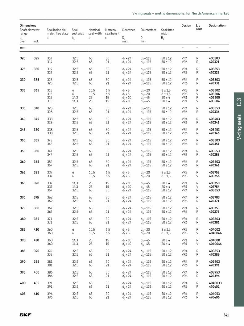
Dimensions Design Lip code
Designation
Shaft diameter range
Seal inside dia -meter, free state
Seal seat width
Nominal seal width
Nominal seal height
Clearance Counterface Seal itted width
d1 d b1 b c D1 D B1over incl. max. min.
mm – – –
320 325 314 32,5 65 30 d1 + 24 d1 + 115 50 ± 12 VR4 R 403203314 32,5 65 21 d1 + 24 d1 + 115 50 ± 12 VR6 R 470321
325 330 319 32,5 65 30 d1 + 24 d1 + 115 50 ± 12 VR4 R 403253319 32,5 65 21 d1 + 24 d1 + 115 50 ± 12 VR6 R 470326
330 335 323 32,5 65 30 d1 + 24 d1 + 115 50 ± 12 VR4 R 403303323 32,5 65 21 d1 + 24 d1 + 115 50 ± 12 VR6 R 470331
335 365 315 6 10,5 6,5 d1 + 5 d1 + 20 8 ± 1,5 VR3 R 403502315 6 10,5 6,5 d1 + 5 d1 + 20 8 ± 1,5 VR3 V 403506315 14,3 25 15 d1 + 10 d1 + 45 20 ± 4 VR1 R 403500315 14,3 25 15 d1 + 10 d1 + 45 20 ± 4 VR1 V 403504
335 340 328 32,5 65 30 d1 + 24 d1 + 115 50 ± 12 VR4 R 403353328 32,5 65 21 d1 + 24 d1 + 115 50 ± 12 VR6 R 470336
340 345 333 32,5 65 30 d1 + 24 d1 + 115 50 ± 12 VR4 R 403403328 32,5 65 21 d1 + 24 d1 + 115 50 ± 12 VR6 R 470341
345 350 338 32,5 65 30 d1 + 24 d1 + 115 50 ± 12 VR4 R 403453338 32,5 65 21 d1 + 24 d1 + 115 50 ± 12 VR6 R 470346
350 355 343 32,5 65 30 d1 + 24 d1 + 115 50 ± 12 VR4 R 403503343 32,5 65 21 d1 + 24 d1 + 115 50 ± 12 VR6 R 470351
355 360 347 32,5 65 30 d1 + 24 d1 + 115 50 ± 12 VR4 R 403553347 32,5 65 21 d1 + 24 d1 + 115 50 ± 12 VR6 R 470356
360 365 352 32,5 65 30 d1 + 24 d1 + 115 50 ± 12 VR4 R 403603357 32,5 65 21 d1 + 24 d1 + 115 50 ± 12 VR6 R 470361
365 385 337 6 10,5 6,5 d1 + 5 d1 + 20 8 ± 1,5 VR3 R 403752337 6 10,5 6,5 d1 + 5 d1 + 20 8 ± 1,5 VR3 V 403756
365 390 337 14,3 25 15 d1 + 10 d1 + 45 20 ± 4 VR1 R 403750337 14,3 25 15 d1 + 10 d1 + 45 20 ± 4 VR1 V 403754357 32,5 65 30 d1 + 24 d1 + 115 50 ± 12 VR4 R 403653
370 375 362 32,5 65 30 d1 + 24 d1 + 115 50 ± 12 VR4 R 403703362 32,5 65 21 d1 + 24 d1 + 115 50 ± 12 VR6 R 470371
375 380 367 32,5 65 30 d1 + 24 d1 + 115 50 ± 12 VR4 R 403753367 32,5 65 21 d1 + 24 d1 + 115 50 ± 12 VR6 R 470376
380 385 371 32,5 65 30 d1 + 24 d1 + 115 50 ± 12 VR4 R 403803371 32,5 65 21 d1 + 24 d1 + 115 50 ± 12 VR6 R 470381
385 410 360 6 10,5 6,5 d1 + 5 d1 + 20 8 ± 1,5 VR3 R 404002360 6 10,5 6,5 d1 + 5 d1 + 20 8 ± 1,5 VR3 V 4040066
390 430 360 14,3 25 15 d1 + 10 d1 + 45 20 ± 4 VR1 R 404000360 14,3 25 15 d1 + 10 d1 + 45 20 ± 4 VR1 V 4040044
385 390 376 32,5 65 30 d1 + 24 d1 + 115 50 ± 12 VR4 R 403853376 32,5 65 21 d1 + 24 d1 + 115 50 ± 12 VR6 R 470386
390 395 381 32,5 65 30 d1 + 24 d1 + 115 50 ± 12 VR4 R 403903381 32,5 65 21 d1 + 24 d1 + 115 50 ± 12 VR6 R 470391
395 400 386 32,5 65 30 d1 + 24 d1 + 115 50 ± 12 VR4 R 403953386 32,5 65 21 d1 + 24 d1 + 115 50 ± 12 VR6 R 470396
400 405 391 32,5 65 30 d1 + 24 d1 + 115 50 ± 12 VR4 R 4040033391 32,5 65 21 d1 + 24 d1 + 115 50 ± 12 VR6 R 470401
405 410 396 32,5 65 30 d1 + 24 d1 + 115 50 ± 12 VR4 R 404053396 32,5 65 21 d1 + 24 d1 + 115 50 ± 12 VR6 R 470406
341341
DE
F
G
H
I
V-r
ing s
eals
C.3
V-ring seals – metric dimensions, for North American market

Dimensions Design Lip code
Designation
Shaft diameter range
Seal inside dia -meter, free state
Seal seat width
Nominal seal width
Nominal seal height
Clearance Counterface Seal itted width
d1 d b1 b c D1 D B1over incl. max. min.
mm – – –
410 415 401 32,5 65 30 d1 + 24 d1 + 115 50 ± 12 VR4 R 404103401 32,5 65 21 d1 + 24 d1 + 115 50 ± 12 VR6 R 470411
415 420 405 32,5 65 30 d1 + 24 d1 + 115 50 ± 12 VR4 R 404153405 32,5 65 21 d1 + 24 d1 + 115 50 ± 12 VR6 R 470416
420 425 410 32,5 65 30 d1 + 24 d1 + 115 50 ± 12 VR4 R 404203410 32,5 65 21 d1 + 24 d1 + 115 50 ± 12 VR6 R 470421
425 430 415 32,5 65 30 d1 + 24 d1 + 115 50 ± 12 VR4 R 404253415 32,5 65 21 d1 + 24 d1 + 115 50 ± 12 VR6 R 470426
410 440 382 6 10,5 6,5 d1 + 5 d1 + 20 8 ± 1,5 VR3 R 404252382 6 10,5 6,5 d1 + 5 d1 + 20 8 ± 1,5 VR3 V 404256
440 475 405 6 10,5 6,5 d1 + 5 d1 + 20 8 ± 1,5 VR3 R 404502405 6 10,5 6,5 d1 + 5 d1 + 20 8 ± 1,5 VR3 V 404506
430 480 405 14,3 25 15 d1 + 10 d1 + 45 20 ± 4 VR1 R 404500405 14,3 25 15 d1 + 10 d1 + 45 20 ± 4 VR1 V 404504
430 435 420 32,5 65 30 d1 + 24 d1 + 115 50 ± 12 VR4 R 404303420 32,5 65 21 d1 + 24 d1 + 115 50 ± 12 VR6 R 470431
435 440 425 32,5 65 30 d1 + 24 d1 + 115 50 ± 12 VR4 R 404353425 32,5 65 21 d1 + 24 d1 + 115 50 ± 12 VR6 R 470436
440 445 429 32,5 65 30 d1 + 24 d1 + 115 50 ± 12 VR4 R 4044033429 32,5 65 21 d1 + 24 d1 + 115 50 ± 12 VR6 R 470441
445 450 434 32,5 65 30 d1 + 24 d1 + 115 50 ± 12 VR4 R 404453434 32,5 65 21 d1 + 24 d1 + 115 50 ± 12 VR6 R 470446
450 455 439 32,5 65 30 d1 + 24 d1 + 115 50 ± 12 VR4 R 404503439 32,5 65 21 d1 + 24 d1 + 115 50 ± 12 VR6 R 470451
455 460 444 32,5 65 30 d1 + 24 d1 + 115 50 ± 12 VR4 R 404553444 32,5 65 21 d1 + 24 d1 + 115 50 ± 12 VR6 R 470456
460 465 448 32,5 65 30 d1 + 24 d1 + 115 50 ± 12 VR4 R 4046033448 32,5 65 21 d1 + 24 d1 + 115 50 ± 12 VR6 R 470461
465 470 453 32,5 65 30 d1 + 24 d1 + 115 50 ± 12 VR4 R 404653453 32,5 65 21 d1 + 24 d1 + 115 50 ± 12 VR6 R 470466
342342
b
b1
B1
d1 D
c
d D1
Axial shaft seals | V-ring seals – metric dimensions, for North American market
d1 410–560 mm

Dimensions Design Lip code
Designation
Shaft diameter range
Seal inside dia -meter, free state
Seal seat width
Nominal seal width
Nominal seal height
Clearance Counterface Seal itted width
d1 d b1 b c D1 D B1over incl. max. min.
mm – – –
470 475 458 32,5 65 30 d1 + 24 d1 + 115 50 ± 12 VR4 R 404703458 32,5 65 21 d1 + 24 d1 + 115 50 ± 12 VR6 R 470471
475 480 463 32,5 65 30 d1 + 24 d1 + 115 50 ± 12 VR4 R 404753463 32,5 65 21 d1 + 24 d1 + 115 50 ± 12 VR6 R 470476
475 510 450 6 10,5 6,5 d1 + 5 d1 + 20 8 ± 1,5 VR3 R 405002450 6 10,5 6,5 d1 + 5 d1 + 20 8 ± 1,5 VR3 V 405009
510 540 472 6 10,5 6,5 d1 + 5 d1 + 20 8 ± 1,5 VR3 R 405252472 6 10,5 6,5 d1 + 5 d1 + 20 8 ± 1,5 VR3 V 405256
480 530 450 14,3 25 15 d1 + 10 d1 + 45 20 ± 4 VR1 R 405000450 14,3 25 15 d1 + 10 d1 + 45 20 ± 4 VR1 V 405004
480 485 468 32,5 65 30 d1 + 24 d1 + 115 50 ± 12 VR4 R 404803468 32,5 65 21 d1 + 24 d1 + 115 50 ± 12 VR6 R 470481
485 490 473 32,5 65 30 d1 + 24 d1 + 115 50 ± 12 VR4 R 404853473 32,5 65 21 d1 + 24 d1 + 115 50 ± 12 VR6 R 470486
490 495 478 32,5 65 30 d1 + 24 d1 + 115 50 ± 12 VR4 R 404903478 32,5 65 21 d1 + 24 d1 + 115 50 ± 12 VR6 R 470491
495 500 483 32,5 65 30 d1 + 24 d1 + 115 50 ± 12 VR4 R 404953483 32,5 65 21 d1 + 24 d1 + 115 50 ± 12 VR6 R 470496
500 505 488 32,5 65 30 d1 + 24 d1 + 115 50 ± 12 VR4 R 405003488 32,5 65 21 d1 + 24 d1 + 115 50 ± 12 VR6 R 470501
505 510 493 32,5 65 30 d1 + 24 d1 + 115 50 ± 12 VR4 R 405053493 32,5 65 21 d1 + 24 d1 + 115 50 ± 12 VR6 R 470506
510 515 497 32,5 65 30 d1 + 24 d1 + 115 50 ± 12 VR4 R 405103497 32,5 65 21 d1 + 24 d1 + 115 50 ± 12 VR6 R 470511
515 520 502 32,5 65 30 d1 + 24 d1 + 115 50 ± 12 VR4 R 405153502 32,5 65 21 d1 + 24 d1 + 115 50 ± 12 VR6 R 470516
520 525 507 32,5 65 30 d1 + 24 d1 + 115 50 ± 12 VR4 R 405203507 32,5 65 21 d1 + 24 d1 + 115 50 ± 12 VR6 R 470521
525 530 512 32,5 65 30 d1 + 24 d1 + 115 50 ± 12 VR4 R 405253512 32,5 65 21 d1 + 24 d1 + 115 50 ± 12 VR6 R 470526
540 575 495 6 10,5 6,5 d1 + 5 d1 + 20 8 ± 1,5 VR3 R 405502495 6 10,5 6,5 d1 + 5 d1 + 20 8 ± 1,5 VR3 V 405506
530 580 495 14,3 25 15 d1 + 10 d1 + 45 20 ± 4 VR1 R 405500495 14,3 25 15 d1 + 10 d1 + 45 20 ± 4 VR1 V 405504
530 535 517 32,5 65 30 d1 + 24 d1 + 115 50 ± 12 VR4 R 405303517 32,5 65 21 d1 + 24 d1 + 115 50 ± 12 VR6 R 470531
535 540 521 32,5 65 30 d1 + 24 d1 + 115 50 ± 12 VR4 R 405353521 32,5 65 21 d1 + 24 d1 + 115 50 ± 12 VR6 R 470536
540 545 526 32,5 65 30 d1 + 24 d1 + 115 50 ± 12 VR4 R 405403526 32,5 65 21 d1 + 24 d1 + 115 50 ± 12 VR6 R 470541
545 550 531 32,5 65 30 d1 + 24 d1 + 115 50 ± 12 VR4 R 405453531 32,5 65 21 d1 + 24 d1 + 115 50 ± 12 VR6 R 470546
550 555 536 32,5 65 30 d1 + 24 d1 + 115 50 ± 12 VR4 R 405503536 32,5 65 21 d1 + 24 d1 + 115 50 ± 12 VR6 R 470551
555 560 541 32,5 65 30 d1 + 24 d1 + 115 50 ± 12 VR4 R 405553541 32,5 65 21 d1 + 24 d1 + 115 50 ± 12 VR6 R 470556
343343
DE
F
G
H
I
V-r
ing s
eals
C.3
V-ring seals – metric dimensions, for North American market

Dimensions Design Lip code
Designation
Shaft diameter range
Seal inside dia -meter, free state
Seal seat width
Nominal seal width
Nominal seal height
Clearance Counterface Seal itted width
d1 d b1 b c D1 D B1over incl. max. min.
mm – – –
560 565 546 32,5 65 30 d1 + 24 d1 + 115 50 ± 12 VR4 R 405603546 32,5 65 21 d1 + 24 d1 + 115 50 ± 12 VR6 R 470561
565 570 550 32,5 65 30 d1 + 24 d1 + 115 50 ± 12 VR4 R 405653550 32,5 65 21 d1 + 24 d1 + 115 50 ± 12 VR6 R 470566
570 575 555 32,5 65 30 d1 + 24 d1 + 115 50 ± 12 VR4 R 405703555 32,5 65 21 d1 + 24 d1 + 115 50 ± 12 VR6 R 470571
575 580 560 32,5 65 30 d1 + 24 d1 + 115 50 ± 12 VR4 R 405753560 32,5 65 21 d1 + 24 d1 + 115 50 ± 12 VR6 R 470576
575 625 540 6 10,5 6,5 d1 + 5 d1 + 20 8 ± 1,5 VR3 R 4060022540 6 10,5 6,5 d1 + 5 d1 + 20 8 ± 1,5 VR3 V 406006
580 630 540 14,3 25 15 d1 + 10 d1 + 45 20 ± 4 VR1 R 406000540 14,3 25 15 d1 + 10 d1 + 45 20 ± 4 VR1 V 4060044
580 585 565 32,5 65 30 d1 + 24 d1 + 115 50 ± 12 VR4 R 405803565 32,5 65 21 d1 + 24 d1 + 115 50 ± 12 VR6 R 470581
585 590 570 32,5 65 30 d1 + 24 d1 + 115 50 ± 12 VR4 R 405853570 32,5 65 21 d1 + 24 d1 + 115 50 ± 12 VR6 R 470586
590 600 575 32,5 65 30 d1 + 24 d1 + 115 50 ± 12 VR4 R 405903575 32,5 65 21 d1 + 24 d1 + 115 50 ± 12 VR6 R 470591
600 610 582 32,5 65 30 d1 + 24 d1 + 115 50 ± 12 VR4 R 406003582 32,5 65 21 d1 + 24 d1 + 115 50 ± 12 VR6 R 470601
610 620 592 32,5 65 30 d1 + 24 d1 + 115 50 ± 12 VR4 R 4061033592 32,5 65 21 d1 + 24 d1 + 115 50 ± 12 VR6 R 470611
620 630 602 32,5 65 30 d1 + 24 d1 + 115 50 ± 12 VR4 R 4062033602 32,5 65 21 d1 + 24 d1 + 115 50 ± 12 VR6 R 470621
615 675 600 6 10,5 6,5 d1 + 5 d1 + 20 8 ± 1,5 VR3 R 406502600 6 10,5 6,5 d1 + 5 d1 + 20 8 ± 1,5 VR3 V 406506
630 665 600 14,3 25 15 d1 + 10 d1 + 45 20 ± 4 VR1 R 406500600 14,3 25 15 d1 + 10 d1 + 45 20 ± 4 VR1 V 406504
630 640 612 32,5 65 30 d1 + 24 d1 + 115 50 ± 12 VR4 R 4063033612 32,5 65 21 d1 + 24 d1 + 115 50 ± 12 VR6 R 470631
344344
b
b1
B1
d1 D
c
d D1
Axial shaft seals | V-ring seals – metric dimensions, for North American market
d1 560–825 mm

Dimensions Design Lip code
Designation
Shaft diameter range
Seal inside dia -meter, free state
Seal seat width
Nominal seal width
Nominal seal height
Clearance Counterface Seal itted width
d1 d b1 b c D1 D B1over incl. max. min.
mm – – –
640 650 621 32,5 65 30 d1 + 24 d1 + 115 50 ± 12 VR4 R 4064033621 32,5 65 21 d1 + 24 d1 + 115 50 ± 12 VR6 R 470641
650 660 631 32,5 65 30 d1 + 24 d1 + 115 50 ± 12 VR4 R 406503631 32,5 65 21 d1 + 24 d1 + 115 50 ± 12 VR6 R 470651
660 670 640 32,5 65 30 d1 + 24 d1 + 115 50 ± 12 VR4 R 4066033640 32,5 65 21 d1 + 24 d1 + 115 50 ± 12 VR6 R 470661
675 710 630 6 10,5 6,5 d1 + 5 d1 + 20 8 ± 1,5 VR3 R 407002630 6 10,5 6,5 d1 + 5 d1 + 20 8 ± 1,5 VR3 V 407006
665 705 630 14,3 25 15 d1 + 10 d1 + 45 20 ± 4 VR1 R 407000630 14,3 25 15 d1 + 10 d1 + 45 20 ± 4 VR1 V 407004
670 680 650 32,5 65 30 d1 + 24 d1 + 115 50 ± 12 VR4 R 406703650 32,5 65 21 d1 + 24 d1 + 115 50 ± 12 VR6 R 470671
680 690 660 32,5 65 30 d1 + 24 d1 + 115 50 ± 12 VR4 R 406803660 32,5 65 21 d1 + 24 d1 + 115 50 ± 12 VR6 R 470681
690 700 670 32,5 65 30 d1 + 24 d1 + 115 50 ± 12 VR4 R 406903670 32,5 65 21 d1 + 24 d1 + 115 50 ± 12 VR6 R 470691
700 710 680 32,5 65 30 d1 + 24 d1 + 115 50 ± 12 VR4 R 407003680 32,5 65 21 d1 + 24 d1 + 115 50 ± 12 VR6 R 470701
710 740 670 6 10,5 6,5 d1 + 5 d1 + 20 8 ± 1,5 VR3 R 407252670 6 10,5 6,5 d1 + 5 d1 + 20 8 ± 1,5 VR3 V 407256
705 745 670 14,3 25 15 d1 + 10 d1 + 45 20 ± 4 VR1 R 407250670 14,3 25 15 d1 + 10 d1 + 45 20 ± 4 VR1 V 407254
710 720 689 32,5 65 30 d1 + 24 d1 + 115 50 ± 12 VR4 R 407103689 32,5 65 21 d1 + 24 d1 + 115 50 ± 12 VR6 R 470711
720 730 699 32,5 65 30 d1 + 24 d1 + 115 50 ± 12 VR4 R 407203699 32,5 65 21 d1 + 24 d1 + 115 50 ± 12 VR6 R 470721
730 740 709 32,5 65 30 d1 + 24 d1 + 115 50 ± 12 VR4 R 407309709 32,5 65 21 d1 + 24 d1 + 115 50 ± 12 VR6 R 470731
740 750 718 32,5 65 30 d1 + 24 d1 + 115 50 ± 12 VR4 R 407403718 32,5 65 21 d1 + 24 d1 + 115 50 ± 12 VR6 R 470741
740 775 705 6 10,5 6,5 d1 + 5 d1 + 20 8 ± 1,5 VR3 R 407502705 6 10,5 6,5 d1 + 5 d1 + 20 8 ± 1,5 VR3 V 407506
745 785 705 14,3 25 15 d1 + 10 d1 + 45 20 ± 4 VR1 R 407500705 14,3 25 15 d1 + 10 d1 + 45 20 ± 4 VR1 V 407504
750 758 728 32,5 65 30 d1 + 24 d1 + 115 50 ± 12 VR4 R 407503728 32,5 65 21 d1 + 24 d1 + 115 50 ± 12 VR6 R 470751
758 766 735 32,5 65 30 d1 + 24 d1 + 115 50 ± 12 VR4 R 407603735 32,5 65 21 d1 + 24 d1 + 115 50 ± 12 VR6 R 470761
766 774 743 32,5 65 30 d1 + 24 d1 + 115 50 ± 12 VR4 R 407703743 32,5 65 21 d1 + 24 d1 + 115 50 ± 12 VR6 R 470771
774 783 751 32,5 65 30 d1 + 24 d1 + 115 50 ± 12 VR4 R 407803751 32,5 65 21 d1 + 24 d1 + 115 50 ± 12 VR6 R 470781
783 792 759 32,5 65 30 d1 + 24 d1 + 115 50 ± 12 VR4 R 407903759 32,5 65 21 d1 + 24 d1 + 115 50 ± 12 VR6 R 470791
775 825 745 6 10,5 6,5 d1 + 5 d1 + 20 8 ± 1,5 VR3 R 408002745 6 10,5 6,5 d1 + 5 d1 + 20 8 ± 1,5 VR3 V 408006
345345
DE
F
G
H
I
V-r
ing s
eals
C.3
V-ring seals – metric dimensions, for North American market

Dimensions Design Lip code
Designation
Shaft diameter range
Seal inside dia -meter, free state
Seal seat width
Nominal seal width
Nominal seal height
Clearance Counterface Seal itted width
d1 d b1 b c D1 D B1over incl. max. min.
mm – – –
785 830 745 14,3 25 15 d1 + 10 d1 + 45 20 ± 4 VR1 R 408000745 14,3 25 15 d1 + 10 d1 + 45 20 ± 4 VR1 V 408004
792 801 768 32,5 65 30 d1 + 24 d1 + 115 50 ± 12 VR4 R 408003768 32,5 65 21 d1 + 24 d1 + 115 50 ± 12 VR6 R 470801
801 810 777 32,5 65 30 d1 + 24 d1 + 115 50 ± 12 VR4 R 408103777 32,5 65 21 d1 + 24 d1 + 115 50 ± 12 VR6 R 470811
810 821 786 32,5 65 30 d1 + 24 d1 + 115 50 ± 12 VR4 R 408203786 32,5 65 21 d1 + 24 d1 + 115 50 ± 12 VR6 R 470821
821 831 796 32,5 65 30 d1 + 24 d1 + 115 50 ± 12 VR4 R 408303796 32,5 65 21 d1 + 24 d1 + 115 50 ± 12 VR6 R 470831
825 875 785 6 10,5 6,5 d1 + 5 d1 + 20 8 ± 1,5 VR3 R 408502785 6 10,5 6,5 d1 + 5 d1 + 20 8 ± 1,5 VR3 V 408506
830 875 785 14,3 25 15 d1 + 10 d1 + 45 20 ± 4 VR1 R 408500785 14,3 25 15 d1 + 10 d1 + 45 20 ± 4 VR1 V 408504
831 841 805 32,5 65 30 d1 + 24 d1 + 115 50 ± 12 VR4 R 408403805 32,5 65 21 d1 + 24 d1 + 115 50 ± 12 VR6 R 470841
841 851 814 32,5 65 30 d1 + 24 d1 + 115 50 ± 12 VR4 R 408503814 32,5 65 21 d1 + 24 d1 + 115 50 ± 12 VR6 R 470851
851 861 824 32,5 65 30 d1 + 24 d1 + 115 50 ± 12 VR4 R 408603824 32,5 65 21 d1 + 24 d1 + 115 50 ± 12 VR6 R 470861
861 871 833 32,5 65 30 d1 + 24 d1 + 115 50 ± 12 VR4 R 408703833 32,5 65 21 d1 + 24 d1 + 115 50 ± 12 VR6 R 470871
871 882 843 32,5 65 30 d1 + 24 d1 + 115 50 ± 12 VR4 R 408803843 32,5 65 21 d1 + 24 d1 + 115 50 ± 12 VR6 R 470881
875 925 825 6 10,5 6,5 d1 + 5 d1 + 20 8 ± 1,5 VR3 R 409002825 6 10,5 6,5 d1 + 5 d1 + 20 8 ± 1,5 VR3 V 409006
875 920 825 14,3 25 15 d1 + 10 d1 + 45 20 ± 4 VR1 R 409000825 14,3 25 15 d1 + 10 d1 + 45 20 ± 4 VR1 V 409004
882 892 853 32,5 65 30 d1 + 24 d1 + 115 50 ± 12 VR4 R 408903853 32,5 65 21 d1 + 24 d1 + 115 50 ± 12 VR6 R 470891
346346
b
b1
B1
d1 D
c
d D1
Axial shaft seals | V-ring seals – metric dimensions, for North American market
d1 785–1 125 mm

Dimensions Design Lip code
Designation
Shaft diameter range
Seal inside dia -meter, free state
Seal seat width
Nominal seal width
Nominal seal height
Clearance Counterface Seal itted width
d1 d b1 b c D1 D B1over incl. max. min.
mm – – –
892 912 871 32,5 65 30 d1 + 24 d1 + 115 50 ± 12 VR4 R 409003871 32,5 65 21 d1 + 24 d1 + 115 50 ± 12 VR6 R 470901
912 922 880 32,5 65 30 d1 + 24 d1 + 115 50 ± 12 VR4 R 409203880 32,5 65 21 d1 + 24 d1 + 115 50 ± 12 VR6 R 470921
925 975 865 6 10,5 6,5 d1 + 5 d1 + 20 8 ± 1,5 VR3 R 409502865 6 10,5 6,5 d1 + 5 d1 + 20 8 ± 1,5 VR3 V 409506
920 965 865 14,3 25 15 d1 + 10 d1 + 45 20 ± 4 VR1 R 409500865 14,3 25 15 d1 + 10 d1 + 45 20 ± 4 VR1 V 409504
922 933 890 32,5 65 30 d1 + 24 d1 + 115 50 ± 12 VR4 R 409303890 32,5 65 21 d1 + 24 d1 + 115 50 ± 12 VR6 R 470931
933 944 900 32,5 65 30 d1 + 24 d1 + 115 50 ± 12 VR4 R 409403900 32,5 65 21 d1 + 24 d1 + 115 50 ± 12 VR6 R 470941
944 955 911 32,5 65 30 d1 + 24 d1 + 115 50 ± 12 VR4 R 409503911 32,5 65 21 d1 + 24 d1 + 115 50 ± 12 VR6 R 470951
955 966 921 32,5 65 30 d1 + 24 d1 + 115 50 ± 12 VR4 R 409603921 32,5 65 21 d1 + 24 d1 + 115 50 ± 12 VR6 R 470961
975 1 025 910 6 10,5 6,5 d1 + 5 d1 + 20 8 ± 1,5 VR3 R 410002910 6 10,5 6,5 d1 + 5 d1 + 20 8 ± 1,5 VR3 V 410006
965 1 015 910 14,3 25 15 d1 + 10 d1 + 45 20 ± 4 VR1 R 410000910 14,3 25 15 d1 + 10 d1 + 45 20 ± 4 VR1 V 410004
966 977 932 32,5 65 30 d1 + 24 d1 + 115 50 ± 12 VR4 R 409703932 32,5 65 21 d1 + 24 d1 + 115 50 ± 12 VR6 R 470971
977 988 942 32,5 65 30 d1 + 24 d1 + 115 50 ± 12 VR4 R 409803942 32,5 65 21 d1 + 24 d1 + 115 50 ± 12 VR6 R 470981
988 999 953 32,5 65 30 d1 + 24 d1 + 115 50 ± 12 VR4 R 409903953 32,5 65 21 d1 + 24 d1 + 115 50 ± 12 VR6 R 470991
999 1 010 963 32,5 65 30 d1 + 24 d1 + 115 50 ± 12 VR4 R 410003963 32,5 65 21 d1 + 24 d1 + 115 50 ± 12 VR6 R 471001
1 010 1 025 973 32,5 65 30 d1 + 24 d1 + 115 50 ± 12 VR4 R 410203973 32,5 65 21 d1 + 24 d1 + 115 50 ± 12 VR6 R 471021
1 025 1 075 955 6 10,5 6,5 d1 + 5 d1 + 20 8 ± 1,5 VR3 R 410502955 6 10,5 6,5 d1 + 5 d1 + 20 8 ± 1,5 VR3 V 410506
1 015 1 065 955 14,3 25 15 d1 + 10 d1 + 45 20 ± 4 VR1 R 410500
1 025 1 045 990 32,5 65 30 d1 + 24 d1 + 115 50 ± 12 VR4 R 410403990 32,5 65 21 d1 + 24 d1 + 115 50 ± 12 VR6 R 471041
1 045 1 065 1 008 32,5 65 30 d1 + 24 d1 + 115 50 ± 12 VR4 R 4106031 008 32,5 65 21 d1 + 24 d1 + 115 50 ± 12 VR6 R 471061
1 075 1 125 1 000 6 10,5 6,5 d1 + 5 d1 + 20 8 ± 1,5 VR3 R 4110021 000 6 10,5 6,5 d1 + 5 d1 + 20 8 ± 1,5 VR3 V 411006
1 065 1 115 1 000 14,3 25 15 d1 + 10 d1 + 45 20 ± 4 VR1 R 4110001 027 32,5 65 30 d1 + 24 d1 + 115 50 ± 12 VR4 R 4108031 027 32,5 65 21 d1 + 24 d1 + 115 50 ± 12 VR6 R 471081
1 085 1 105 1 045 32,5 65 30 d1 + 24 d1 + 115 50 ± 12 VR4 R 4110031 045 32,5 65 21 d1 + 24 d1 + 115 50 ± 12 VR6 R 471101
1 105 1 125 1 065 32,5 65 30 d1 + 24 d1 + 115 50 ± 12 VR4 R 4112031 065 32,5 65 21 d1 + 24 d1 + 115 50 ± 12 VR6 R 471121
347347
DE
F
G
H
I
V-r
ing s
eals
C.3
V-ring seals – metric dimensions, for North American market

Dimensions Design Lip code
Designation
Shaft diameter range
Seal inside dia -meter, free state
Seal seat width
Nominal seal width
Nominal seal height
Clearance Counterface Seal itted width
d1 d b1 b c D1 D B1over incl. max. min.
mm – – –
1 125 1 175 1 045 6 10,5 6,5 d1 + 5 d1 + 20 8 ± 1,5 VR3 R 4115021 045 6 10,5 6,5 d1 + 5 d1 + 20 8 ± 1,5 VR3 V 411506
1 115 1 165 1 045 14,3 25 15 d1 + 10 d1 + 45 20 ± 4 VR1 R 411500
1 125 1 145 1 084 32,5 65 30 d1 + 24 d1 + 115 50 ± 12 VR4 R 4114031 084 32,5 65 21 d1 + 24 d1 + 115 50 ± 12 VR6 R 471141
1 145 1 165 1 103 32,5 65 30 d1 + 24 d1 + 115 50 ± 12 VR4 R 4116031 103 32,5 65 21 d1 + 24 d1 + 115 50 ± 12 VR6 R 471161
1 175 1 225 1 090 6 10,5 6,5 d1 + 5 d1 + 20 8 ± 1,5 VR3 R 4120021 090 6 10,5 6,5 d1 + 5 d1 + 20 8 ± 1,5 VR3 V 412006
1 165 1 215 1 090 14,3 25 15 d1 + 10 d1 + 45 20 ± 4 VR1 R 412000
1 165 1 185 1 121 32,5 65 30 d1 + 24 d1 + 115 50 ± 12 VR4 R 4118031 121 32,5 65 21 d1 + 24 d1 + 115 50 ± 12 VR6 R 471181
1 185 1 205 1 139 32,5 65 30 d1 + 24 d1 + 115 50 ± 12 VR4 R 4120031 139 32,5 65 21 d1 + 24 d1 + 115 50 ± 12 VR6 R 471201
1 205 1 225 1 157 32,5 65 30 d1 + 24 d1 + 115 50 ± 12 VR4 R 4122031 157 32,5 65 21 d1 + 24 d1 + 115 50 ± 12 VR6 R 471221
1 225 1 275 1 135 6 10,5 6,5 d1 + 5 d1 + 20 8 ± 1,5 VR3 R 4125021 135 6 10,5 6,5 d1 + 5 d1 + 20 8 ± 1,5 VR3 V 412506
1 215 1 270 1 135 14,3 25 15 d1 + 10 d1 + 45 20 ± 4 VR1 R 412500
1 225 1 245 1 176 32,5 65 30 d1 + 24 d1 + 115 50 ± 12 VR4 R 4712401 176 32,5 65 21 d1 + 24 d1 + 115 50 ± 12 VR6 R 471241
1 245 1 270 1 195 32,5 65 30 d1 + 24 d1 + 115 50 ± 12 VR4 R 4126031 195 32,5 65 21 d1 + 24 d1 + 115 50 ± 12 VR6 R 471261
1 270 1 295 1 218 32,5 65 30 d1 + 24 d1 + 115 50 ± 12 VR4 R 4128031 218 32,5 65 21 d1 + 24 d1 + 115 50 ± 12 VR6 R 471281
1 275 1 325 1 180 6 10,5 6,5 d1 + 5 d1 + 20 8 ± 1,5 VR3 R 4130021 180 6 10,5 6,5 d1 + 5 d1 + 20 8 ± 1,5 VR3 V 413006
1 270 1 320 1 180 14,3 25 15 d1 + 10 d1 + 45 20 ± 4 VR1 R 413000
348348
b
b1
B1
d1 D
c
d D1
Axial shaft seals | V-ring seals – metric dimensions, for North American market
d1 1 125–1640 mm

Dimensions Design Lip code
Designation
Shaft diameter range
Seal inside dia -meter, free state
Seal seat width
Nominal seal width
Nominal seal height
Clearance Counterface Seal itted width
d1 d b1 b c D1 D B1over incl. max. min.
mm – – –
1 295 1 315 1 240 32,5 65 30 d1 + 24 d1 + 115 50 ± 12 VR4 R 4130031 240 32,5 65 21 d1 + 24 d1 + 115 50 ± 12 VR6 R 471301
1 315 1 340 1 259 32,5 65 30 d1 + 24 d1 + 115 50 ± 12 VR4 R 4132531 259 32,5 65 21 d1 + 24 d1 + 115 50 ± 12 VR6 R 471326
1 325 1 375 1 225 6 10,5 6,5 d1 + 5 d1 + 20 8 ± 1,5 VR3 R 4135021 225 6 10,5 6,5 d1 + 5 d1 + 20 8 ± 1,5 VR3 V 413506
1 320 1 370 1 225 14,3 25 15 d1 + 10 d1 + 45 20 ± 4 VR1 R 413500
1 340 1 365 1 281 32,5 65 30 d1 + 24 d1 + 115 50 ± 12 VR4 R 4135031 281 32,5 65 21 d1 + 24 d1 + 115 50 ± 12 VR6 R 471351
1 365 1 390 1 305 32,5 65 30 d1 + 24 d1 + 115 50 ± 12 VR4 R 4137531 305 32,5 65 21 d1 + 24 d1 + 115 50 ± 12 VR6 R 471376
1 375 1 425 1 270 6 10,5 6,5 d1 + 5 d1 + 20 8 ± 1,5 VR3 R 4140021 270 6 10,5 6,5 d1 + 5 d1 + 20 8 ± 1,5 VR3 V 414006
1 370 1 420 1 270 14,3 25 15 d1 + 10 d1 + 45 20 ± 4 VR1 R 414000
1 390 1 415 1 328 32,5 65 30 d1 + 24 d1 + 115 50 ± 12 VR4 R 4140031 328 32,5 65 21 d1 + 24 d1 + 115 50 ± 12 VR6 R 471401
1 415 1 440 1 350 32,5 65 30 d1 + 24 d1 + 115 50 ± 12 VR4 R 4142531 350 32,5 65 21 d1 + 24 d1 + 115 50 ± 12 VR6 R 471426
1 425 1 475 1 315 6 10,5 6,5 d1 + 5 d1 + 20 8 ± 1,5 VR3 R 4145021 315 6 10,5 6,5 d1 + 5 d1 + 20 8 ± 1,5 VR3 V 414506
1 420 1 470 1 315 14,3 25 15 d1 + 10 d1 + 45 20 ± 4 VR1 R 414500
1 440 1 465 1 374 32,5 65 30 d1 + 24 d1 + 115 50 ± 12 VR4 R 4145031 374 32,5 65 21 d1 + 24 d1 + 115 50 ± 12 VR6 R 471451
1 465 1 490 1 397 32,5 65 30 d1 + 24 d1 + 115 50 ± 12 VR4 R 4147531 397 32,5 65 21 d1 + 24 d1 + 115 50 ± 12 VR6 R 471476
1 475 1 525 1 360 6 10,5 6,5 d1 + 5 d1 + 20 8 ± 1,5 VR3 R 4150021 360 6 10,5 6,5 d1 + 5 d1 + 20 8 ± 1,5 VR3 V 415006
1 470 1 520 1 360 14,3 25 15 d1 + 10 d1 + 45 20 ± 4 VR1 R 415000
1 490 1 515 1 419 32,5 65 30 d1 + 24 d1 + 115 50 ± 12 VR4 R 4150031 419 32,5 65 21 d1 + 24 d1 + 115 50 ± 12 VR6 R 471501
1 515 1 540 1 443 32,5 65 30 d1 + 24 d1 + 115 50 ± 12 VR4 R 4152531 443 32,5 65 21 d1 + 24 d1 + 115 50 ± 12 VR6 R 471526
1 525 1 575 1 405 6 10,5 6,5 d1 + 5 d1 + 20 8 ± 1,5 VR3 R 4155021 405 6 10,5 6,5 d1 + 5 d1 + 20 8 ± 1,5 VR3 V 415506
1 520 1 570 1 405 14,3 25 15 d1 + 10 d1 + 45 20 ± 4 VR1 R 415500
1 540 1 570 1 467 32,5 65 30 d1 + 24 d1 + 115 50 ± 12 VR4 R 4155031 467 32,5 65 21 d1 + 24 d1 + 115 50 ± 12 VR6 R 471551
1 570 1 600 1 495 32,5 65 30 d1 + 24 d1 + 115 50 ± 12 VR4 R 4157531 495 32,5 65 21 d1 + 24 d1 + 115 50 ± 12 VR6 R 471576
1 575 1 625 1 450 6 10,5 6,5 d1 + 5 d1 + 20 8 ± 1,5 VR3 R 4160021 450 6 10,5 6,5 d1 + 5 d1 + 20 8 ± 1,5 VR3 V 416006
1 570 1 620 1 450 14,3 25 15 d1 + 10 d1 + 45 20 ± 4 VR1 R 416000
1 600 1 640 1 524 32,5 65 30 d1 + 24 d1 + 115 50 ± 12 VR4 R 4160031 524 32,5 65 21 d1 + 24 d1 + 115 50 ± 12 VR6 R 471601
349349
DE
F
G
H
I
V-r
ing s
eals
C.3
V-ring seals – metric dimensions, for North American market

Dimensions Design Lip code
Designation
Shaft diameter range
Seal inside dia -meter, free state
Seal seat width
Nominal seal width
Nominal seal height
Clearance Counterface Seal itted width
d1 d b1 b c D1 D B1over incl. max. min.
mm – – –
1 625 1 675 1 495 6 10,5 6,5 d1 + 5 d1 + 20 8 ± 1,5 VR3 R 4165021 495 6 10,5 6,5 d1 + 5 d1 + 20 8 ± 1,5 VR3 V 416506
1 620 1 670 1 495 14,3 25 15 d1 + 10 d1 + 45 20 ± 4 VR1 R 416500
1 640 1 680 1 559 32,5 65 30 d1 + 24 d1 + 115 50 ± 12 VR4 R 4165031 559 32,5 65 21 d1 + 24 d1 + 115 50 ± 12 VR6 R 471651
1 675 1 725 1 540 6 10,5 6,5 d1 + 5 d1 + 20 8 ± 1,5 VR3 R 4170021 540 6 10,5 6,5 d1 + 5 d1 + 20 8 ± 1,5 VR3 V 417006
1 670 1 720 1 540 14,3 25 15 d1 + 10 d1 + 45 20 ± 4 VR1 R 417000
1 680 1 720 1 596 32,5 65 30 d1 + 24 d1 + 115 50 ± 12 VR4 R 4170031 596 32,5 65 21 d1 + 24 d1 + 115 50 ± 12 VR6 R 471701
1 725 1 775 1 585 6 10,5 6,5 d1 + 5 d1 + 20 8 ± 1,5 VR3 R 4175021 585 6 10,5 6,5 d1 + 5 d1 + 20 8 ± 1,5 VR3 V 417506
1 720 1 770 1 585 14,3 25 15 d1 + 10 d1 + 45 20 ± 4 VR1 R 417500
1 720 1 765 1 632 32,5 65 30 d1 + 24 d1 + 115 50 ± 12 VR4 R 4175031 632 32,5 65 21 d1 + 24 d1 + 115 50 ± 12 VR6 R 471751
1 765 1 810 1 671 32,5 65 30 d1 + 24 d1 + 115 50 ± 12 VR4 R 4180031 671 32,5 65 21 d1 + 24 d1 + 115 50 ± 12 VR6 R 471801
1 775 1 825 1 630 6 10,5 6,5 d1 + 5 d1 + 20 8 ± 1,5 VR3 R 4180021 630 6 10,5 6,5 d1 + 5 d1 + 20 8 ± 1,5 VR3 V 418006
1 770 1 820 1 630 14,3 25 15 d1 + 10 d1 + 45 20 ± 4 VR1 R 418000
1 810 1 855 1 714 32,5 65 30 d1 + 24 d1 + 115 50 ± 12 VR4 R 4185031 714 32,5 65 21 d1 + 24 d1 + 115 50 ± 12 VR6 R 471851
1 825 1 875 1 675 6 10,5 6,5 d1 + 5 d1 + 20 8 ± 1,5 VR3 R 4185021 675 6 10,5 6,5 d1 + 5 d1 + 20 8 ± 1,5 VR3 V 418506
1 820 1 870 1 675 14,3 25 15 d1 + 10 d1 + 45 20 ± 4 VR1 R 418500
1 855 1 905 1 753 32,5 65 30 d1 + 24 d1 + 115 50 ± 12 VR4 R 4190031 753 32,5 65 21 d1 + 24 d1 + 115 50 ± 12 VR6 R 471901
350350
b
b1
B1
d1 D
c
d D1
Axial shaft seals | V-ring seals – metric dimensions, for North American market
d1 1 625–2 020 mm

Dimensions Design Lip code
Designation
Shaft diameter range
Seal inside dia -meter, free state
Seal seat width
Nominal seal width
Nominal seal height
Clearance Counterface Seal itted width
d1 d b1 b c D1 D B1over incl. max. min.
mm – – –
1 875 1 925 1 720 6 10,5 6,5 d1 + 5 d1 + 20 8 ± 1,5 VR3 R 4190021 720 6 10,5 6,5 d1 + 5 d1 + 20 8 ± 1,5 VR3 V 419006
1 870 1 920 1 720 14,3 25 15 d1 + 10 d1 + 45 20 ± 4 VR1 R 419000
1 905 1 955 1 794 32,5 65 30 d1 + 24 d1 + 115 50 ± 12 VR4 R 4195031 794 32,5 65 21 d1 + 24 d1 + 115 50 ± 12 VR6 R 471951
1 925 1 975 1 765 6 10,5 6,5 d1 + 5 d1 + 20 8 ± 1,5 VR3 R 4195021 765 6 10,5 6,5 d1 + 5 d1 + 20 8 ± 1,5 VR3 V 419506
1 920 1 970 1 765 14,3 25 15 d1 + 10 d1 + 45 20 ± 4 VR1 R 419500
1 955 2 010 1 844 32,5 65 30 d1 + 24 d1 + 115 50 ± 12 VR4 R 4200031 844 32,5 65 21 d1 + 24 d1 + 115 50 ± 12 VR6 R 472001
1 975 2 025 1 810 6 10,5 6,5 d1 + 5 d1 + 20 8 ± 1,5 VR3 R 4200021 810 6 10,5 6,5 d1 + 5 d1 + 20 8 ± 1,5 VR3 V 420006
1 970 2 020 1 810 14,3 25 15 d1 + 10 d1 + 45 20 ± 4 VR1 R 420000
351351
DE
F
G
H
I
V-r
ing s
eals
C.3
V-ring seals – metric dimensions, for North American market

Dimensions Design Lip code
Designation
Shaft diameter range
Seal inside dia -meter, free state
Nominal seal height
Seal seat width
Nominal seal width
Clearance D1 (= d1 +)
Counterface D (= d1 +)
Seal itted width
d1 d c b1 b D1 D B1over incl. max. min.
in in – – –
0.11 0.14 0.10 0.06 0.08 0.12 0.04 0.16 0.10 ± 0.012 VR1 R 4000300.10 0.06 0.08 0.12 0.04 0.16 0.10 ± 0.012 VR1 V 400034
0.14 0.18 0.13 0.08 0.09 0.15 0.04 0.24 0.12 ± 0.016 VR1 R 4000400.13 0.08 0.09 0.15 0.04 0.24 0.12 ± 0.016 VR1 V 400044
0.18 0.22 0.16 0.08 0.09 0.15 0.04 0.24 0.12 ± 0.016 VR1 R 4000500.16 0.08 0.09 0.15 0.04 0.24 0.12 ± 0.016 VR1 V 4000540.16 0.08 0.15 0.20 0.04 0.24 0.18 ± 0.016 VR2 R 4000510.16 0.08 0.15 0.20 0.04 0.24 0.18 ± 0.016 VR2 V 400055
0.22 0.26 0.20 0.08 0.09 0.15 0.04 0.24 0.12 ± 0.016 VR1 R 4000600.20 0.08 0.09 0.15 0.04 0.24 0.12 ± 0.016 VR1 V 4000640.20 0.08 0.15 0.20 0.04 0.24 0.18 ± 0.016 VR2 R 4000610.20 0.08 0.15 0.20 0.04 0.24 0.18 ± 0.016 VR2 V 400065
0.26 0.31 0.24 0.08 0.09 0.15 0.04 0.24 0.12 ± 0.016 VR1 R 4000700.24 0.08 0.09 0.15 0.04 0.24 0.12 ± 0.016 VR1 V 4000740.24 0.08 0.15 0.20 0.04 0.24 0.18 ± 0.016 VR2 R 4000710.24 0.08 0.15 0.20 0.04 0.24 0.18 ± 0.016 VR2 V 400075
0.31 0.37 0.28 0.08 0.09 0.15 0.04 0.24 0.12 ± 0.016 VR1 R 4000800.28 0.08 0.09 0.15 0.04 0.24 0.12 ± 0.016 VR1 V 4000840.28 0.08 0.15 0.20 0.04 0.24 0.18 ± 0.016 VR2 R 4000810.28 0.08 0.15 0.20 0.04 0.24 0.18 ± 0.016 VR2 V 400085
0.37 0.45 0.35 0.12 0.13 0.22 0.04 0.35 0.18 ± 0.02 VR1 R 4001000.35 0.12 0.13 0.22 0.04 0.35 0.18 ± 0.02 VR1 V 4001040.35 0.12 0.22 0.30 0.04 0.35 0.26 ± 0.02 VR2 R 4001010.35 0.12 0.22 0.30 0.04 0.35 0.26 ± 0.02 VR2 V 400105
0.45 0.49 0.41 0.12 0.13 0.22 0.04 0.35 0.18 ± 0.02 VR1 R 4001200.41 0.12 0.13 0.22 0.04 0.35 0.18 ± 0.02 VR1 V 4001240.41 0.12 0.22 0.30 0.04 0.35 0.26 ± 0.02 VR2 R 4001210.41 0.12 0.22 0.30 0.04 0.35 0.26 ± 0.02 VR2 V 400125
0.49 0.53 0.46 0.12 0.13 0.22 0.04 0.35 0.18 ± 0.02 VR1 R 4001300.46 0.12 0.13 0.22 0.04 0.35 0.18 ± 0.02 VR1 V 400134
0.53 0.61 0.49 0.12 0.13 0.22 0.04 0.35 0.18 ± 0.02 VR1 R 4001400.49 0.12 0.13 0.22 0.04 0.35 0.18 ± 0.02 VR1 V 400144
0.53 0.61 0.49 0.12 0.22 0.30 0.04 0.35 0.26 ± 0.02 VR2 R 4001410.49 0.12 0.22 0.30 0.04 0.35 0.26 ± 0.02 VR2 V 400145
352352
b
b1
B1
d1 D
c
d D1
Axial shaft seals | V-ring seals – inch dimensions, for North American market
d1 0.11–2.28 in

Dimensions Design Lip code
Designation
Shaft diameter range
Seal inside dia -meter, free state
Nominal seal height
Seal seat width
Nominal seal width
Clearance D1 (= d1 +)
Counterface D (= d1 +)
Seal itted width
d1 d c b1 b D1 D B1over incl. max. min.
in in – – –
0.61 0.67 0.55 0.12 0.13 0.22 0.04 0.35 0.18 ± 0.02 VR1 R 4001600.55 0.12 0.13 0.22 0.04 0.35 0.18 ± 0.02 VR1 V 400164
0.61 0.69 0.55 0.12 0.22 0.30 0.04 0.35 0.26 ± 0.02 VR2 R 4001610.55 0.12 0.22 0.30 0.04 0.35 0.26 ± 0.02 VR2 V 400165
0.69 0.75 0.63 0.12 0.13 0.22 0.04 0.35 0.18 ± 0.02 VR1 R 4001800.63 0.12 0.13 0.22 0.04 0.35 0.18 ± 0.02 VR1 V 4001840.63 0.12 0.22 0.30 0.04 0.35 0.26 ± 0.02 VR2 R 4001810.63 0.12 0.22 0.30 0.04 0.35 0.26 ± 0.02 VR2 V 400185
0.75 0.83 0.71 0.16 0.19 0.30 0.08 0.47 0.24 ± 0.03 VR1 R 4002000.71 0.16 0.19 0.30 0.08 0.47 0.24 ± 0.03 VR1 V 4002040.71 0.16 0.31 0.41 0.08 0.47 0.35 ± 0.03 VR2 R 4002010.71 0.16 0.31 0.41 0.08 0.47 0.35 ± 0.03 VR2 V 400205
0.83 0.94 0.79 0.16 0.19 0.30 0.08 0.47 0.24 ± 0.03 VR1 R 4002200.79 0.16 0.19 0.30 0.08 0.47 0.24 ± 0.03 VR1 V 4002240.79 0.16 0.31 0.41 0.08 0.47 0.35 ± 0.03 VR2 R 4002210.79 0.16 0.31 0.41 0.08 0.47 0.35 ± 0.03 VR2 V 400225
0.94 1.06 0.87 0.16 0.19 0.30 0.08 0.47 0.24 ± 0.03 VR1 R 4002500.87 0.16 0.19 0.30 0.08 0.47 0.24 ± 0.03 VR1 V 4002540.87 0.16 0.31 0.41 0.08 0.47 0.35 ± 0.03 VR2 R 4002510.87 0.16 0.31 0.41 0.08 0.47 0.35 ± 0.03 VR2 V 400255
1.06 1.14 0.98 0.16 0.19 0.30 0.08 0.47 0.24 ± 0.03 VR1 R 4002800.98 0.16 0.19 0.30 0.08 0.47 0.24 ± 0.03 VR1 V 4002840.98 0.16 0.31 0.41 0.08 0.47 0.35 ± 0.03 VR2 R 4002810.98 0.16 0.31 0.41 0.08 0.47 0.35 ± 0.03 VR2 V 400285
1.14 1.22 1.06 0.16 0.19 0.30 0.08 0.47 0.24 ± 0.03 VR1 R 4003001.06 0.16 0.19 0.30 0.08 0.47 0.24 ± 0.03 VR1 V 4003041.06 0.16 0.31 0.41 0.08 0.47 0.35 ± 0.03 VR2 R 4003011.06 0.16 0.31 0.41 0.08 0.47 0.35 ± 0.03 VR2 V 400305
1.22 1.30 1.14 0.16 0.19 0.30 0.08 0.47 0.24 ± 0.03 VR1 R 4003201.14 0.16 0.19 0.30 0.08 0.47 0.24 ± 0.03 VR1 V 4003241.14 0.16 0.31 0.41 0.08 0.47 0.35 ± 0.03 VR2 R 4003211.14 0.16 0.31 0.41 0.08 0.47 0.35 ± 0.03 VR2 V 400325
1.30 1.42 1.22 0.16 0.19 0.30 0.08 0.47 0.24 ± 0.03 VR1 R 4003501.22 0.16 0.19 0.30 0.08 0.47 0.24 ± 0.03 VR1 V 4003541.22 0.16 0.31 0.41 0.08 0.47 0.35 ± 0.03 VR2 R 4003511.22 0.16 0.31 0.41 0.08 0.47 0.35 ± 0.03 VR2 V 400355
1.42 1.50 1.34 0.16 0.19 0.30 0.08 0.47 0.24 ± 0.03 VR1 R 4003801.34 0.16 0.19 0.30 0.08 0.47 0.24 ± 0.03 VR1 V 4003841.34 0.16 0.31 0.41 0.08 0.47 0.35 ± 0.03 VR2 R 4003811.34 0.16 0.31 0.41 0.08 0.47 0.35 ± 0.03 VR2 V 400385
1.50 1.69 1.42 0.20 0.22 0.35 0.08 0.59 0.28 ± 0.04 VR1 R 4004001.42 0.20 0.22 0.35 0.08 0.59 0.28 ± 0.04 VR1 V 4004091.42 0.20 0.37 0.51 0.08 0.59 0.43 ± 0.04 VR2 R 4004011.42 0.20 0.37 0.51 0.08 0.59 0.43 ± 0.04 VR2 V 400405
1.69 1.89 1.57 0.20 0.22 0.35 0.08 0.59 0.28 ± 0.04 VR1 R 4004501.57 0.20 0.22 0.35 0.08 0.59 0.28 ± 0.04 VR1 V 4004541.57 0.20 0.37 0.51 0.08 0.59 0.43 ± 0.04 VR2 R 4004511.57 0.20 0.37 0.51 0.08 0.59 0.43 ± 0.04 VR2 V 400455
1.89 2.09 1.77 0.20 0.22 0.35 0.08 0.59 0.28 ± 0.04 VR1 R 4005001.77 0.20 0.22 0.35 0.08 0.59 0.28 ± 0.04 VR1 V 4005041.77 0.20 0.37 0.51 0.08 0.59 0.43 ± 0.04 VR2 R 4005011.77 0.20 0.37 0.51 0.08 0.59 0.43 ± 0.04 VR2 V 400505
2.09 2.28 1.93 0.20 0.22 0.35 0.08 0.59 0.28 ± 0.04 VR1 R 4005501.93 0.20 0.22 0.35 0.08 0.59 0.28 ± 0.04 VR1 V 4005541.93 0.20 0.37 0.51 0.08 0.59 0.43 ± 0.04 VR2 R 4005511.93 0.20 0.37 0.51 0.08 0.59 0.43 ± 0.04 VR2 V 400555
353353
DE
F
G
H
I
V-r
ing s
eals
C.3
V-ring seals – inch dimensions, for North American market

Dimensions Design Lip code
Designation
Shaft diameter range
Seal inside dia -meter, free state
Nominal seal height
Seal seat width
Nominal seal width
Clearance D1 (= d1 +)
Counterface D (= d1 +)
Seal itted width
d1 d c b1 b D1 D B1over incl. max. min.
in in – – –
2.28 2.48 2.13 0.20 0.22 0.35 0.08 0.59 0.28 ± 0.04 VR1 R 4006002.13 0.20 0.22 0.35 0.08 0.59 0.28 ± 0.04 VR1 V 4006042.13 0.20 0.37 0.51 0.08 0.59 0.43 ± 0.04 VR2 R 4006012.13 0.20 0.37 0.51 0.08 0.59 0.43 ± 0.04 VR2 V 400605
2.48 2.68 2.28 0.20 0.22 0.35 0.08 0.59 0.28 ± 0.04 VR1 R 4006502.28 0.20 0.22 0.35 0.08 0.59 0.28 ± 0.04 VR1 V 4006542.28 0.20 0.37 0.51 0.08 0.59 0.43 ± 0.04 VR2 R 4006512.28 0.20 0.37 0.51 0.08 0.59 0.43 ± 0.04 VR2 V 400655
2.68 2.87 2.48 0.24 0.27 0.43 0.12 0.71 0.35 ± 0.05 VR1 R 4007002.48 0.24 0.27 0.43 0.12 0.71 0.35 ± 0.05 VR1 V 4007042.48 0.24 0.44 0.61 0.12 0.71 0.53 ± 0.05 VR2 R 4007012.48 0.24 0.44 0.61 0.12 0.71 0.53 ± 0.05 VR2 V 400705
2.87 3.07 2.64 0.24 0.27 0.43 0.12 0.71 0.35 ± 0.05 VR1 R 4007502.64 0.24 0.27 0.43 0.12 0.71 0.53 ± 0.05 VR2 R 4007512.64 0.24 0.44 0.61 0.12 0.71 0.53 ± 0.05 VR2 V 400755
3.07 3.27 2.83 0.24 0.27 0.43 0.12 0.71 0.35 ± 0.05 VR1 R 4008002.83 0.24 0.27 0.43 0.12 0.71 0.35 ± 0.05 VR1 V 4008042.83 0.24 0.44 0.61 0.12 0.71 0.53 ± 0.05 VR2 R 4008012.83 0.24 0.44 0.61 0.12 0.71 0.53 ± 0.05 VR2 V 400805
3.27 3.46 2.99 0.24 0.27 0.43 0.12 0.71 0.35 ± 0.05 VR1 R 4008502.99 0.24 0.27 0.43 0.12 0.71 0.35 ± 0.05 VR1 V 4008542.99 0.24 0.44 0.61 0.12 0.71 0.53 ± 0.05 VR2 R 4008512.99 0.24 0.44 0.61 0.12 0.71 0.53 ± 0.05 VR2 V 400855
3.46 3.66 3.19 0.24 0.27 0.43 0.12 0.71 0.35 ± 0.05 VR1 R 4009003.19 0.24 0.27 0.43 0.12 0.71 0.35 ± 0.05 VR1 V 4009043.19 0.24 0.44 0.61 0.12 0.71 0.53 ± 0.05 VR2 R 4009013.19 0.24 0.44 0.61 0.12 0.71 0.53 ± 0.05 VR2 V 400905
3.66 3.86 3.35 0.24 0.27 0.43 0.12 0.71 0.35 ± 0.05 VR1 R 4009503.35 0.24 0.27 0.43 0.12 0.71 0.35 ± 0.05 VR1 V 4009543.35 0.24 0.44 0.61 0.12 0.71 0.53 ± 0.05 VR2 R 4009513.35 0.24 0.44 0.61 0.12 0.71 0.53 ± 0.05 VR2 V 400955
3.86 4.13 3.54 0.24 0.27 0.43 0.12 0.71 0.35 ± 0.05 VR1 R 4010003.54 0.24 0.27 0.43 0.12 0.71 0.35 ± 0.05 VR1 V 4010043.54 0.24 0.44 0.61 0.12 0.71 0.53 ± 0.05 VR2 R 4010013.54 0.24 0.44 0.61 0.12 0.71 0.53 ± 0.05 VR2 V 401005
354354
b
b1
B1
d1 D
c
d D1
Axial shaft seals | V-ring seals – inch dimensions, for North American market
d1 2.28–8.27 in

Dimensions Design Lip code
Designation
Shaft diameter range
Seal inside dia -meter, free state
Nominal seal height
Seal seat width
Nominal seal width
Clearance D1 (= d1 +)
Counterface D (= d1 +)
Seal itted width
d1 d c b1 b D1 D B1over incl. max. min.
in in – – –
4.13 4.53 3.90 0.26 0.24 0.41 0.20 0.79 0.31 ± 0.06 VR3 R 4011023.90 0.26 0.24 0.41 0.20 0.79 0.31 ± 0.06 VR3 V 4011063.90 0.28 0.31 0.50 0.16 0.83 0.41 ± 0.06 VR1 R 4011003.90 0.28 0.31 0.50 0.16 0.83 0.41 ± 0.06 VR1 V 4011043.90 0.28 0.52 0.71 0.16 0.83 0.61 ± 0.06 VR2 R 4011013.90 0.28 0.52 0.71 0.16 0.83 0.61 ± 0.06 VR2 V 401105
4.53 4.92 4.25 0.26 0.24 0.41 0.20 0.79 0.31 ± 0.06 VR3 R 4012024.25 0.26 0.24 0.41 0.20 0.79 0.31 ± 0.06 VR3 V 4012064.25 0.28 0.31 0.50 0.16 0.83 0.41 ± 0.06 VR1 R 4012004.25 0.28 0.31 0.50 0.16 0.83 0.41 ± 0.06 VR1 V 4012044.25 0.28 0.52 0.71 0.16 0.83 0.61 ± 0.06 VR2 R 4012014.25 0.28 0.52 0.71 0.16 0.83 0.61 ± 0.06 VR2 V 401205
4.92 5.31 4.61 0.26 0.24 0.41 0.20 0.79 0.31 ± 0.06 VR3 R 4013024.61 0.26 0.24 0.41 0.20 0.79 0.31 ± 0.06 VR3 V 4013064.61 0.28 0.31 0.50 0.16 0.83 0.41 ± 0.06 VR1 R 4013004.61 0.28 0.31 0.50 0.16 0.83 0.41 ± 0.06 VR1 V 4013044.61 0.28 0.52 0.71 0.16 0.83 0.61 ± 0.06 VR2 R 4013014.61 0.28 0.52 0.71 0.16 0.83 0.61 ± 0.06 VR2 V 401305
5.31 5.71 4.96 0.26 0.24 0.41 0.20 0.79 0.31 ± 0.06 VR3 R 4014024.96 0.26 0.24 0.41 0.20 0.79 0.31 ± 0.06 VR3 V 4014064.96 0.28 0.31 0.50 0.16 0.83 0.41 ± 0.06 VR1 R 4014004.96 0.28 0.31 0.50 0.16 0.83 0.41 ± 0.06 VR1 V 4014044.96 0.28 0.52 0.71 0.16 0.83 0.61 ± 0.06 VR2 R 4014014.96 0.28 0.52 0.71 0.16 0.83 0.61 ± 0.06 VR2 V 401405
5.71 6.10 5.31 0.26 0.24 0.41 0.20 0.79 0.31 ± 0.06 VR3 R 4015025.31 0.26 0.24 0.41 0.20 0.79 0.31 ± 0.06 VR3 V 4015065.31 0.28 0.31 0.50 0.16 0.83 0.41 ± 0.06 VR1 R 4015005.31 0.28 0.31 0.50 0.16 0.83 0.41 ± 0.06 VR1 V 4015045.31 0.28 0.52 0.71 0.16 0.83 0.61 ± 0.06 VR2 R 4015015.31 0.28 0.52 0.71 0.16 0.83 0.61 ± 0.06 VR2 V 401505
6.10 6.50 5.67 0.26 0.24 0.41 0.20 0.79 0.31 ± 0.06 VR3 R 4016025.67 0.26 0.24 0.41 0.20 0.79 0.31 ± 0.06 VR3 V 4016065.67 0.31 0.35 0.57 0.16 0.94 0.47 ± 0.07 VR1 R 4016005.67 0.31 0.35 0.57 0.16 0.94 0.47 ± 0.07 VR1 V 4016045.67 0.31 0.59 0.81 0.16 0.94 0.71 ± 0.07 VR2 R 4016015.67 0.31 0.59 0.81 0.16 0.94 0.71 ± 0.07 VR2 V 401605
6.50 6.89 6.02 0.26 0.24 0.41 0.20 0.79 0.31 ± 0.06 VR3 R 4017026.02 0.26 0.24 0.41 0.20 0.79 0.31 ± 0.06 VR3 V 4017066.02 0.31 0.35 0.57 0.16 0.94 0.47 ± 0.07 VR1 R 4017006.02 0.31 0.35 0.57 0.16 0.94 0.47 ± 0.07 VR1 V 4017046.02 0.31 0.59 0.81 0.16 0.94 0.71 ± 0.07 VR2 R 4017016.02 0.31 0.59 0.81 0.16 0.94 0.71 ± 0.07 VR2 V 401705
6.89 7.28 6.38 0.26 0.24 0.41 0.20 0.79 0.31 ± 0.06 VR3 R 4018026.38 0.26 0.24 0.41 0.20 0.79 0.31 ± 0.06 VR3 V 4018066.38 0.31 0.35 0.57 0.16 0.94 0.47 ± 0.07 VR1 R 4018006.38 0.31 0.35 0.57 0.16 0.94 0.47 ± 0.07 VR1 V 4018046.38 0.31 0.59 0.81 0.16 0.94 0.71 ± 0.07 VR2 R 4018016.38 0.31 0.59 0.81 0.16 0.94 0.71 ± 0.07 VR2 V 401805
7.28 7.68 6.73 0.26 0.24 0.41 0.20 0.79 0.31 ± 0.06 VR3 R 4019026.73 0.26 0.24 0.41 0.20 0.79 0.31 ± 0.06 VR3 V 4019066.73 0.31 0.35 0.57 0.16 0.94 0.47 ± 0.07 VR1 R 4019006.73 0.31 0.35 0.57 0.16 0.94 0.47 ± 0.07 VR1 V 4019046.73 0.31 0.59 0.81 0.16 0.94 0.71 ± 0.07 VR2 R 4019016.73 0.31 0.59 0.81 0.16 0.94 0.71 ± 0.07 VR2 V 401905
7.68 8.27 7.17 0.26 0.24 0.41 0.20 0.79 0.31 ± 0.06 VR3 R 40200227.17 0.26 0.24 0.41 0.20 0.79 0.31 ± 0.06 VR3 V 4020067.09 0.31 0.35 0.57 0.16 0.94 0.47 ± 0.07 VR1 R 4019907.09 0.31 0.35 0.57 0.16 0.94 0.47 ± 0.07 VR1 V 4019947.09 0.31 0.59 0.81 0.16 0.94 0.71 ± 0.07 VR2 R 4019917.09 0.31 0.59 0.81 0.16 0.94 0.71 ± 0.07 VR2 V 401995
355355
DE
F
G
H
I
V-r
ing s
eals
C.3
V-ring seals – inch dimensions, for North American market

Dimensions Design Lip code
Designation
Shaft diameter range
Seal inside dia -meter, free state
Nominal seal height
Seal seat width
Nominal seal width
Clearance D1 (= d1 +)
Counterface D (= d1 +)
Seal itted width
d1 d c b1 b D1 D B1over incl. max. min.
in in – – –
7.48 8.27 7.09 0.59 0.56 0.98 0.39 1.77 0.79 ± 0.16 VR1 R 4020007.09 0.59 0.56 0.98 0.39 1.77 0.79 ± 0.16 VR1 V 402004
8.27 9.17 7.80 0.26 0.24 0.41 0.20 0.79 0.31 ± 0.06 VR3 R 4022027.80 0.26 0.24 0.41 0.20 0.79 0.31 ± 0.06 VR3 V 4022067.80 0.59 0.56 0.98 0.39 1.77 0.79 ± 0.16 VR1 R 4022007.80 0.59 0.56 0.98 0.39 1.77 0.79 ± 0.16 VR1 V 402204
9.17 10.24 8.86 0.26 0.24 0.41 0.20 0.79 0.31 ± 0.06 VR3 R 4025028.86 0.26 0.24 0.41 0.20 0.79 0.31 ± 0.06 VR3 V 402506
9.25 10.43 8.86 0.59 0.56 0.98 0.39 1.77 0.79 ± 0.16 VR1 R 4025008.86 0.59 0.56 0.98 0.39 1.77 0.79 ± 0.16 VR1 V 402504
10.24 11.22 9.72 0.26 0.24 0.41 0.20 0.79 0.31 ± 0.06 VR3 R 4027529.72 0.26 0.24 0.41 0.20 0.79 0.31 ± 0.06 VR3 V 402756
10.43 11.42 9.72 0.59 0.56 0.98 0.39 1.77 0.79 ± 0.16 VR1 R 4027509.72 0.59 0.56 0.98 0.39 1.77 0.79 ± 0.16 VR1 V 402754
11.22 12.20 10.63 0.26 0.24 0.41 0.20 0.79 0.31 ± 0.06 VR3 R 40300210.63 0.26 0.24 0.41 0.20 0.79 0.31 ± 0.06 VR3 V 403006
11.42 12.20 10.63 0.59 0.56 0.98 0.39 1.77 0.79 ± 0.16 VR1 R 40300010.63 0.59 0.56 0.98 0.39 1.77 0.79 ± 0.16 VR1 V 403004
11.81 12.01 11.57 1.18 1.28 2.56 0.94 4.53 1.97 ± 0.47 VR4 R 40300311.57 0.83 1.28 2.56 0.94 4.53 1.97 ± 0.47 VR6 R 470301
12.01 12.20 11.77 1.18 1.28 2.56 0.94 4.53 1.97 ± 0.47 VR4 R 40305311.77 0.83 1.28 2.56 0.94 4.53 1.97 ± 0.47 VR6 R 470306
12.20 13.19 11.50 0.26 0.24 0.41 0.20 0.79 0.31 ± 0.06 VR3 R 40325211.50 0.26 0.24 0.41 0.20 0.79 0.31 ± 0.06 VR3 V 403256
12.20 13.19 11.50 0.59 0.56 0.98 0.39 1.77 0.79 ± 0.16 VR1 R 40325011.50 0.59 0.56 0.98 0.39 1.77 0.79 ± 0.16 VR1 V 403254
12.20 12.40 11.97 1.18 1.28 2.56 0.94 4.53 1.97 ± 0.47 VR4 R 40310311.97 0.83 1.28 2.56 0.94 4.53 1.97 ± 0.47 VR6 R 470311
12.40 12.60 12.17 1.18 1.28 2.56 0.94 4.53 1.97 ± 0.47 VR4 R 40315312.17 0.83 1.28 2.56 0.94 4.53 1.97 ± 0.47 VR6 R 470316
356356
b
b1
B1
d1 D
c
d D1
Axial shaft seals | V-ring seals – inch dimensions, for North American market
d1 7.48–16.14 in

Dimensions Design Lip code
Designation
Shaft diameter range
Seal inside dia -meter, free state
Nominal seal height
Seal seat width
Nominal seal width
Clearance D1 (= d1 +)
Counterface D (= d1 +)
Seal itted width
d1 d c b1 b D1 D B1over incl. max. min.
in in – – –
12.60 12.80 12.36 1.18 1.28 2.56 0.94 4.53 1.97 ± 0.47 VR4 R 40320312.36 0.83 1.28 2.56 0.94 4.53 1.97 ± 0.47 VR6 R 470321
12.80 12.99 12.56 1.18 1.28 2.56 0.94 4.53 1.97 ± 0.47 VR4 R 40325312.56 0.83 1.28 2.56 0.94 4.53 1.97 ± 0.47 VR6 R 470326
12.99 13.19 12.72 1.18 1.28 2.56 0.94 4.53 1.97 ± 0.47 VR4 R 40330312.72 0.83 1.28 2.56 0.94 4.53 1.97 ± 0.47 VR6 R 470331
13.19 14.37 12.40 0.26 0.24 0.41 0.20 0.79 0.31 ± 0.06 VR3 R 40350212.40 0.26 0.24 0.41 0.20 0.79 0.31 ± 0.06 VR3 V 40350612.40 0.59 0.56 0.98 0.39 1.77 0.79 ± 0.16 VR1 R 40350012.40 0.59 0.56 0.98 0.39 1.77 0.79 ± 0.16 VR1 V 403504
13.19 13.39 12.91 1.18 1.28 2.56 0.94 4.53 1.97 ± 0.47 VR4 R 40335312.91 0.83 1.28 2.56 0.94 4.53 1.97 ± 0.47 VR6 R 470336
13.39 13.58 13.11 1.18 1.28 2.56 0.94 4.53 1.97 ± 0.47 VR4 R 40340312.91 0.83 1.28 2.56 0.94 4.53 1.97 ± 0.47 VR6 R 470341
13.58 13.78 13.31 1.18 1.28 2.56 0.94 4.53 1.97 ± 0.47 VR4 R 40345313.31 0.83 1.28 2.56 0.94 4.53 1.97 ± 0.47 VR6 R 470346
13.78 13.98 13.50 1.18 1.28 2.56 0.94 4.53 1.97 ± 0.47 VR4 R 40350313.50 0.83 1.28 2.56 0.94 4.53 1.97 ± 0.47 VR6 R 470351
13.98 14.17 13.66 1.18 1.28 2.56 0.94 4.53 1.97 ± 0.47 VR4 R 40355313.66 0.83 1.28 2.56 0.94 4.53 1.97 ± 0.47 VR6 R 470356
14.17 14.37 13.86 1.18 1.28 2.56 0.94 4.53 1.97 ± 0.47 VR4 R 40360314.06 0.83 1.28 2.56 0.94 4.53 1.97 ± 0.47 VR6 R 470361
14.37 15.16 13.27 0.26 0.24 0.41 0.20 0.79 0.31 ± 0.06 VR3 R 40375213.27 0.26 0.24 0.41 0.20 0.79 0.31 ± 0.06 VR3 V 403756
14.37 15.35 13.27 0.59 0.56 0.98 0.39 1.77 0.79 ± 0.16 VR1 R 40375013.27 0.59 0.56 0.98 0.39 1.77 0.79 ± 0.16 VR1 V 403754
14.37 14.57 14.06 1.18 1.28 2.56 0.94 4.53 1.97 ± 0.47 VR4 R 403653
14.57 14.76 14.25 1.18 1.28 2.56 0.94 4.53 1.97 ± 0.47 VR4 R 40370314.25 0.83 1.28 2.56 0.94 4.53 1.97 ± 0.47 VR6 R 470371
14.76 14.96 14.45 1.18 1.28 2.56 0.94 4.53 1.97 ± 0.47 VR4 R 40375314.45 0.83 1.28 2.56 0.94 4.53 1.97 ± 0.47 VR6 R 470376
14.96 15.16 14.61 1.18 1.28 2.56 0.94 4.53 1.97 ± 0.47 VR4 R 40380314.61 0.83 1.28 2.56 0.94 4.53 1.97 ± 0.47 VR6 R 470381
15.16 16.14 14.17 0.26 0.24 0.41 0.20 0.79 0.31 ± 0.06 VR3 R 40400214.17 0.26 0.24 0.41 0.20 0.79 0.31 ± 0.06 VR3 V 4040066
15.35 16.93 14.17 0.59 0.56 0.98 0.39 1.77 0.79 ± 0.16 VR1 R 40400014.17 0.59 0.56 0.98 0.39 1.77 0.79 ± 0.16 VR1 V 4040044
15.16 15.35 14.80 1.18 1.28 2.56 0.94 4.53 1.97 ± 0.47 VR4 R 40385314.80 0.83 1.28 2.56 0.94 4.53 1.97 ± 0.47 VR6 R 470386
15.35 15.55 15.00 1.18 1.28 2.56 0.94 4.53 1.97 ± 0.47 VR4 R 40390315.00 0.83 1.28 2.56 0.94 4.53 1.97 ± 0.47 VR6 R 470391
15.55 15.75 15.20 1.18 1.28 2.56 0.94 4.53 1.97 ± 0.47 VR4 R 40395315.20 0.83 1.28 2.56 0.94 4.53 1.97 ± 0.47 VR6 R 470396
15.75 15.94 15.39 1.18 1.28 2.56 0.94 4.53 1.97 ± 0.47 VR4 R 404003315.39 0.83 1.28 2.56 0.94 4.53 1.97 ± 0.47 VR6 R 470401
15.94 16.14 15.59 1.18 1.28 2.56 0.94 4.53 1.97 ± 0.47 VR4 R 40405315.59 0.83 1.28 2.56 0.94 4.53 1.97 ± 0.47 VR6 R 470406
357357
DE
F
G
H
I
V-r
ing s
eals
C.3
V-ring seals – inch dimensions, for North American market

Dimensions Design Lip code
Designation
Shaft diameter range
Seal inside dia -meter, free state
Nominal seal height
Seal seat width
Nominal seal width
Clearance D1 (= d1 +)
Counterface D (= d1 +)
Seal itted width
d1 d c b1 b D1 D B1over incl. max. min.
in in – – –
16.14 16.34 15.79 1.18 1.28 2.56 0.94 4.53 1.97 ± 0.47 VR4 R 40410315.79 0.83 1.28 2.56 0.94 4.53 1.97 ± 0.47 VR6 R 470411
16.34 16.54 15.94 1.18 1.28 2.56 0.94 4.53 1.97 ± 0.47 VR4 R 40415315.94 0.83 1.28 2.56 0.94 4.53 1.97 ± 0.47 VR6 R 470416
16.54 16.73 16.14 1.18 1.28 2.56 0.94 4.53 1.97 ± 0.47 VR4 R 40420316.14 0.83 1.28 2.56 0.94 4.53 1.97 ± 0.47 VR6 R 470421
16.73 16.93 16.34 1.18 1.28 2.56 0.94 4.53 1.97 ± 0.47 VR4 R 40425316.34 0.83 1.28 2.56 0.94 4.53 1.97 ± 0.47 VR6 R 470426
16.14 17.32 15.04 0.26 0.24 0.41 0.20 0.79 0.31 ± 0.06 VR3 R 40425215.04 0.26 0.24 0.41 0.20 0.79 0.31 ± 0.06 VR3 V 404256
17.32 18.70 15.94 0.26 0.24 0.41 0.20 0.79 0.31 ± 0.06 VR3 R 40450215.94 0.26 0.24 0.41 0.20 0.79 0.31 ± 0.06 VR3 V 404506
16.93 18.90 15.94 0.59 0.56 0.98 0.39 1.77 0.79 ± 0.16 VR1 R 40450015.94 0.59 0.56 0.98 0.39 1.77 0.79 ± 0.16 VR1 V 404504
16.93 17.13 16.54 1.18 1.28 2.56 0.94 4.53 1.97 ± 0.47 VR4 R 40430316.54 0.83 1.28 2.56 0.94 4.53 1.97 ± 0.47 VR6 R 470431
17.13 17.32 16.73 1.18 1.28 2.56 0.94 4.53 1.97 ± 0.47 VR4 R 40435316.73 0.83 1.28 2.56 0.94 4.53 1.97 ± 0.47 VR6 R 470436
17.32 17.52 16.89 1.18 1.28 2.56 0.94 4.53 1.97 ± 0.47 VR4 R 404403316.89 0.83 1.28 2.56 0.94 4.53 1.97 ± 0.47 VR6 R 470441
17.52 17.72 17.09 1.18 1.28 2.56 0.94 4.53 1.97 ± 0.47 VR4 R 40445317.09 0.83 1.28 2.56 0.94 4.53 1.97 ± 0.47 VR6 R 470446
17.72 17.91 17.28 1.18 1.28 2.56 0.94 4.53 1.97 ± 0.47 VR4 R 40450317.28 0.83 1.28 2.56 0.94 4.53 1.97 ± 0.47 VR6 R 470451
17.91 18.11 17.48 1.18 1.28 2.56 0.94 4.53 1.97 ± 0.47 VR4 R 40455317.48 0.83 1.28 2.56 0.94 4.53 1.97 ± 0.47 VR6 R 470456
18.11 18.31 17.64 1.18 1.28 2.56 0.94 4.53 1.97 ± 0.47 VR4 R 404603317.64 0.83 1.28 2.56 0.94 4.53 1.97 ± 0.47 VR6 R 470461
18.31 18.50 17.83 1.18 1.28 2.56 0.94 4.53 1.97 ± 0.47 VR4 R 40465317.83 0.83 1.28 2.56 0.94 4.53 1.97 ± 0.47 VR6 R 470466
358358
b
b1
B1
d1 D
c
d D1
Axial shaft seals | V-ring seals – inch dimensions, for North American market
d1 16.14–22.05 in

Dimensions Design Lip code
Designation
Shaft diameter range
Seal inside dia -meter, free state
Nominal seal height
Seal seat width
Nominal seal width
Clearance D1 (= d1 +)
Counterface D (= d1 +)
Seal itted width
d1 d c b1 b D1 D B1over incl. max. min.
in in – – –
18.50 18.70 18.03 1.18 1.28 2.56 0.94 4.53 1.97 ± 0.47 VR4 R 40470318.03 0.83 1.28 2.56 0.94 4.53 1.97 ± 0.47 VR6 R 470471
18.70 18.90 18.23 1.18 1.28 2.56 0.94 4.53 1.97 ± 0.47 VR4 R 40475318.23 0.83 1.28 2.56 0.94 4.53 1.97 ± 0.47 VR6 R 470476
18.70 20.08 17.72 0.26 0.24 0.41 0.20 0.79 0.31 ± 0.06 VR3 R 40500217.72 0.26 0.24 0.41 0.20 0.79 0.31 ± 0.06 VR3 V 405009
20.08 21.26 18.58 0.26 0.24 0.41 0.20 0.79 0.31 ± 0.06 VR3 R 40525218.58 0.26 0.24 0.41 0.20 0.79 0.31 ± 0.06 VR3 V 405256
18.90 20.87 17.72 0.59 0.56 0.98 0.39 1.77 0.79 ± 0.16 VR1 R 40500017.72 0.59 0.56 0.98 0.39 1.77 0.79 ± 0.16 VR1 V 405004
18.90 19.09 18.43 1.18 1.28 2.56 0.94 4.53 1.97 ± 0.47 VR4 R 40480318.43 0.83 1.28 2.56 0.94 4.53 1.97 ± 0.47 VR6 R 470481
19.09 19.29 18.62 1.18 1.28 2.56 0.94 4.53 1.97 ± 0.47 VR4 R 40485318.62 0.83 1.28 2.56 0.94 4.53 1.97 ± 0.47 VR6 R 470486
19.29 19.49 18.82 1.18 1.28 2.56 0.94 4.53 1.97 ± 0.47 VR4 R 40490318.82 0.83 1.28 2.56 0.94 4.53 1.97 ± 0.47 VR6 R 470491
19.49 19.69 19.02 1.18 1.28 2.56 0.94 4.53 1.97 ± 0.47 VR4 R 40495319.02 0.83 1.28 2.56 0.94 4.53 1.97 ± 0.47 VR6 R 470496
19.69 19.88 19.21 1.18 1.28 2.56 0.94 4.53 1.97 ± 0.47 VR4 R 40500319.21 0.83 1.28 2.56 0.94 4.53 1.97 ± 0.47 VR6 R 470501
19.88 20.08 19.41 1.18 1.28 2.56 0.94 4.53 1.97 ± 0.47 VR4 R 40505319.41 0.83 1.28 2.56 0.94 4.53 1.97 ± 0.47 VR6 R 470506
20.08 20.28 19.57 1.18 1.28 2.56 0.94 4.53 1.97 ± 0.47 VR4 R 40510319.57 0.83 1.28 2.56 0.94 4.53 1.97 ± 0.47 VR6 R 470511
20.28 20.47 19.76 1.18 1.28 2.56 0.94 4.53 1.97 ± 0.47 VR4 R 40515319.76 0.83 1.28 2.56 0.94 4.53 1.97 ± 0.47 VR6 R 470516
20.47 20.67 19.96 1.18 1.28 2.56 0.94 4.53 1.97 ± 0.47 VR4 R 40520319.96 0.83 1.28 2.56 0.94 4.53 1.97 ± 0.47 VR6 R 470521
20.67 20.87 20.16 1.18 1.28 2.56 0.94 4.53 1.97 ± 0.47 VR4 R 40525320.16 0.83 1.28 2.56 0.94 4.53 1.97 ± 0.47 VR6 R 470526
21.26 22.64 19.49 0.26 0.24 0.41 0.20 0.79 0.31 ± 0.06 VR3 R 40550219.49 0.26 0.24 0.41 0.20 0.79 0.31 ± 0.06 VR3 V 405506
20.87 22.83 19.49 0.59 0.56 0.98 0.39 1.77 0.79 ± 0.16 VR1 R 40550019.49 0.59 0.56 0.98 0.39 1.77 0.79 ± 0.16 VR1 V 405504
20.87 21.06 20.35 1.18 1.28 2.56 0.94 4.53 1.97 ± 0.47 VR4 R 40530320.35 0.83 1.28 2.56 0.94 4.53 1.97 ± 0.47 VR6 R 470531
21.06 21.26 20.51 1.18 1.28 2.56 0.94 4.53 1.97 ± 0.47 VR4 R 40535320.51 0.83 1.28 2.56 0.94 4.53 1.97 ± 0.47 VR6 R 470536
21.26 21.46 20.71 1.18 1.28 2.56 0.94 4.53 1.97 ± 0.47 VR4 R 40540320.71 0.83 1.28 2.56 0.94 4.53 1.97 ± 0.47 VR6 R 470541
21.46 21.65 20.91 1.18 1.28 2.56 0.94 4.53 1.97 ± 0.47 VR4 R 40545320.91 0.83 1.28 2.56 0.94 4.53 1.97 ± 0.47 VR6 R 470546
21.65 21.85 21.10 1.18 1.28 2.56 0.94 4.53 1.97 ± 0.47 VR4 R 40550321.10 0.83 1.28 2.56 0.94 4.53 1.97 ± 0.47 VR6 R 470551
21.85 22.05 21.30 1.18 1.28 2.56 0.94 4.53 1.97 ± 0.47 VR4 R 40555321.30 0.83 1.28 2.56 0.94 4.53 1.97 ± 0.47 VR6 R 470556
359359
DE
F
G
H
I
V-r
ing s
eals
C.3
V-ring seals – inch dimensions, for North American market

Dimensions Design Lip code
Designation
Shaft diameter range
Seal inside dia -meter, free state
Nominal seal height
Seal seat width
Nominal seal width
Clearance D1 (= d1 +)
Counterface D (= d1 +)
Seal itted width
d1 d c b1 b D1 D B1over incl. max. min.
in in – – –
22.05 22.24 21.50 1.18 1.28 2.56 0.94 4.53 1.97 ± 0.47 VR4 R 40560321.50 0.83 1.28 2.56 0.94 4.53 1.97 ± 0.47 VR6 R 470561
22.24 22.44 21.65 1.18 1.28 2.56 0.94 4.53 1.97 ± 0.47 VR4 R 40565321.65 0.83 1.28 2.56 0.94 4.53 1.97 ± 0.47 VR6 R 470566
22.44 22.64 21.85 1.18 1.28 2.56 0.94 4.53 1.97 ± 0.47 VR4 R 40570321.85 0.83 1.28 2.56 0.94 4.53 1.97 ± 0.47 VR6 R 470571
22.64 22.83 22.05 1.18 1.28 2.56 0.94 4.53 1.97 ± 0.47 VR4 R 40575322.05 0.83 1.28 2.56 0.94 4.53 1.97 ± 0.47 VR6 R 470576
22.64 24.61 21.26 0.26 0.24 0.41 0.20 0.79 0.31 ± 0.06 VR3 R 406002221.26 0.26 0.24 0.41 0.20 0.79 0.31 ± 0.06 VR3 V 406006
22.83 24.80 21.26 0.59 0.56 0.98 0.39 1.77 0.79 ± 0.16 VR1 R 40600021.26 0.59 0.56 0.98 0.39 1.77 0.79 ± 0.16 VR1 V 4060044
22.83 23.03 22.24 1.18 1.28 2.56 0.94 4.53 1.97 ± 0.47 VR4 R 40580322.24 0.83 1.28 2.56 0.94 4.53 1.97 ± 0.47 VR6 R 470581
23.03 23.23 22.44 1.18 1.28 2.56 0.94 4.53 1.97 ± 0.47 VR4 R 40585322.44 0.83 1.28 2.56 0.94 4.53 1.97 ± 0.47 VR6 R 470586
23.23 23.62 22.64 1.18 1.28 2.56 0.94 4.53 1.97 ± 0.47 VR4 R 40590322.64 0.83 1.28 2.56 0.94 4.53 1.97 ± 0.47 VR6 R 470591
23.62 24.02 22.91 1.18 1.28 2.56 0.94 4.53 1.97 ± 0.47 VR4 R 40600322.91 0.83 1.28 2.56 0.94 4.53 1.97 ± 0.47 VR6 R 470601
24.02 24.41 23.31 1.18 1.28 2.56 0.94 4.53 1.97 ± 0.47 VR4 R 406103323.31 0.83 1.28 2.56 0.94 4.53 1.97 ± 0.47 VR6 R 470611
24.41 24.80 23.70 1.18 1.28 2.56 0.94 4.53 1.97 ± 0.47 VR4 R 406203323.70 0.83 1.28 2.56 0.94 4.53 1.97 ± 0.47 VR6 R 470621
24.21 26.57 23.62 0.26 0.24 0.41 0.20 0.79 0.31 ± 0.06 VR3 R 40650223.62 0.26 0.24 0.41 0.20 0.79 0.31 ± 0.06 VR3 V 406506
24.80 26.18 23.62 0.59 0.56 0.98 0.39 1.77 0.79 ± 0.16 VR1 R 40650023.62 0.59 0.56 0.98 0.39 1.77 0.79 ± 0.16 VR1 V 406504
24.80 25.20 24.09 1.18 1.28 2.56 0.94 4.53 1.97 ± 0.47 VR4 R 406303324.09 0.83 1.28 2.56 0.94 4.53 1.97 ± 0.47 VR6 R 470631
360360
b
b1
B1
d1 D
c
d D1
Axial shaft seals | V-ring seals – inch dimensions, for North American market
d1 22.05–32.48 in

Dimensions Design Lip code
Designation
Shaft diameter range
Seal inside dia -meter, free state
Nominal seal height
Seal seat width
Nominal seal width
Clearance D1 (= d1 +)
Counterface D (= d1 +)
Seal itted width
d1 d c b1 b D1 D B1over incl. max. min.
in in – – –
25.20 25.59 24.45 1.18 1.28 2.56 0.94 4.53 1.97 ± 0.47 VR4 R 406403324.45 0.83 1.28 2.56 0.94 4.53 1.97 ± 0.47 VR6 R 470641
25.59 25.98 24.84 1.18 1.28 2.56 0.94 4.53 1.97 ± 0.47 VR4 R 40650324.84 0.83 1.28 2.56 0.94 4.53 1.97 ± 0.47 VR6 R 470651
25.98 26.38 25.20 1.18 1.28 2.56 0.94 4.53 1.97 ± 0.47 VR4 R 406603325.20 0.83 1.28 2.56 0.94 4.53 1.97 ± 0.47 VR6 R 470661
26.57 27.95 24.80 0.26 0.24 0.41 0.20 0.79 0.31 ± 0.06 VR3 R 40700224.80 0.26 0.24 0.41 0.20 0.79 0.31 ± 0.06 VR3 V 407006
26.18 27.76 24.80 0.59 0.56 0.98 0.39 1.77 0.79 ± 0.16 VR1 R 40700024.80 0.59 0.56 0.98 0.39 1.77 0.79 ± 0.16 VR1 V 407004
26.38 26.77 25.59 1.18 1.28 2.56 0.94 4.53 1.97 ± 0.47 VR4 R 40670325.59 0.83 1.28 2.56 0.94 4.53 1.97 ± 0.47 VR6 R 470671
26.77 27.17 25.98 1.18 1.28 2.56 0.94 4.53 1.97 ± 0.47 VR4 R 40680325.98 0.83 1.28 2.56 0.94 4.53 1.97 ± 0.47 VR6 R 470681
27.17 27.56 26.38 1.18 1.28 2.56 0.94 4.53 1.97 ± 0.47 VR4 R 40690326.38 0.83 1.28 2.56 0.94 4.53 1.97 ± 0.47 VR6 R 470691
27.56 27.95 26.77 1.18 1.28 2.56 0.94 4.53 1.97 ± 0.47 VR4 R 40700326.77 0.83 1.28 2.56 0.94 4.53 1.97 ± 0.47 VR6 R 470701
27.95 29.13 26.38 0.26 0.24 0.41 0.20 0.79 0.31 ± 0.06 VR3 R 40725226.38 0.26 0.24 0.41 0.20 0.79 0.31 ± 0.06 VR3 V 407256
27.76 29.33 26.38 0.59 0.56 0.98 0.39 1.77 0.79 ± 0.16 VR1 R 40725026.38 0.59 0.56 0.98 0.39 1.77 0.79 ± 0.16 VR1 V 407254
27.95 28.35 27.13 1.18 1.28 2.56 0.94 4.53 1.97 ± 0.47 VR4 R 40710327.13 0.83 1.28 2.56 0.94 4.53 1.97 ± 0.47 VR6 R 470711
28.35 28.74 27.52 1.18 1.28 2.56 0.94 4.53 1.97 ± 0.47 VR4 R 40720327.52 0.83 1.28 2.56 0.94 4.53 1.97 ± 0.47 VR6 R 470721
28.74 29.13 27.91 1.18 1.28 2.56 0.94 4.53 1.97 ± 0.47 VR4 R 40730927.91 0.83 1.28 2.56 0.94 4.53 1.97 ± 0.47 VR6 R 470731
29.13 29.53 28.27 1.18 1.28 2.56 0.94 4.53 1.97 ± 0.47 VR4 R 40740328.27 0.83 1.28 2.56 0.94 4.53 1.97 ± 0.47 VR6 R 470741
29.13 30.51 27.76 0.26 0.24 0.41 0.20 0.79 0.31 ± 0.06 VR3 R 40750227.76 0.26 0.24 0.41 0.20 0.79 0.31 ± 0.06 VR3 V 407506
29.33 30.91 27.76 0.59 0.56 0.98 0.39 1.77 0.79 ± 0.16 VR1 R 40750027.76 0.59 0.56 0.98 0.39 1.77 0.79 ± 0.16 VR1 V 407504
29.53 29.84 28.66 1.18 1.28 2.56 0.94 4.53 1.97 ± 0.47 VR4 R 40750328.66 0.83 1.28 2.56 0.94 4.53 1.97 ± 0.47 VR6 R 470751
29.84 30.16 28.94 1.18 1.28 2.56 0.94 4.53 1.97 ± 0.47 VR4 R 40760328.94 0.83 1.28 2.56 0.94 4.53 1.97 ± 0.47 VR6 R 470761
30.16 30.47 29.25 1.18 1.28 2.56 0.94 4.53 1.97 ± 0.47 VR4 R 40770329.25 0.83 1.28 2.56 0.94 4.53 1.97 ± 0.47 VR6 R 470771
30.47 30.83 29.57 1.18 1.28 2.56 0.94 4.53 1.97 ± 0.47 VR4 R 40780329.57 0.83 1.28 2.56 0.94 4.53 1.97 ± 0.47 VR6 R 470781
30.83 31.18 29.88 1.18 1.28 2.56 0.94 4.53 1.97 ± 0.47 VR4 R 40790329.88 0.83 1.28 2.56 0.94 4.53 1.97 ± 0.47 VR6 R 470791
30.51 32.48 29.33 0.26 0.24 0.41 0.20 0.79 0.31 ± 0.06 VR3 R 40800229.33 0.26 0.24 0.41 0.20 0.79 0.31 ± 0.06 VR3 V 408006
361361
DE
F
G
H
I
V-r
ing s
eals
C.3
V-ring seals – inch dimensions, for North American market

Dimensions Design Lip code
Designation
Shaft diameter range
Seal inside dia -meter, free state
Nominal seal height
Seal seat width
Nominal seal width
Clearance D1 (= d1 +)
Counterface D (= d1 +)
Seal itted width
d1 d c b1 b D1 D B1over incl. max. min.
in in – – –
30.91 32.68 29.33 0.59 0.56 0.98 0.39 1.77 0.79 ± 0.16 VR1 R 40800029.33 0.59 0.56 0.98 0.39 1.77 0.79 ± 0.16 VR1 V 408004
31.18 31.54 30.24 1.18 1.28 2.56 0.94 4.53 1.97 ± 0.47 VR4 R 40800330.24 0.83 1.28 2.56 0.94 4.53 1.97 ± 0.47 VR6 R 470801
31.54 31.89 30.59 1.18 1.28 2.56 0.94 4.53 1.97 ± 0.47 VR4 R 40810330.59 0.83 1.28 2.56 0.94 4.53 1.97 ± 0.47 VR6 R 470811
31.89 32.32 30.94 1.18 1.28 2.56 0.94 4.53 1.97 ± 0.47 VR4 R 40820330.94 0.83 1.28 2.56 0.94 4.53 1.97 ± 0.47 VR6 R 470821
32.32 32.72 31.34 1.18 1.28 2.56 0.94 4.53 1.97 ± 0.47 VR4 R 40830331.34 0.83 1.28 2.56 0.94 4.53 1.97 ± 0.47 VR6 R 470831
32.48 34.45 30.91 0.26 0.24 0.41 0.20 0.79 0.31 ± 0.06 VR3 R 40850230.91 0.26 0.24 0.41 0.20 0.79 0.31 ± 0.06 VR3 V 408506
32.68 34.45 30.91 0.59 0.56 0.98 0.39 1.77 0.79 ± 0.16 VR1 R 40850030.91 0.59 0.56 0.98 0.39 1.77 0.79 ± 0.16 VR1 V 408504
32.72 33.11 31.69 1.18 1.28 2.56 0.94 4.53 1.97 ± 0.47 VR4 R 40840331.69 0.83 1.28 2.56 0.94 4.53 1.97 ± 0.47 VR6 R 470841
33.11 33.50 32.05 1.18 1.28 2.56 0.94 4.53 1.97 ± 0.47 VR4 R 40850332.05 0.83 1.28 2.56 0.94 4.53 1.97 ± 0.47 VR6 R 470851
33.50 33.90 32.44 1.18 1.28 2.56 0.94 4.53 1.97 ± 0.47 VR4 R 40860332.44 0.83 1.28 2.56 0.94 4.53 1.97 ± 0.47 VR6 R 470861
33.90 34.29 32.80 1.18 1.28 2.56 0.94 4.53 1.97 ± 0.47 VR4 R 40870332.80 0.83 1.28 2.56 0.94 4.53 1.97 ± 0.47 VR6 R 470871
34.29 34.72 33.19 1.18 1.28 2.56 0.94 4.53 1.97 ± 0.47 VR4 R 40880333.19 0.83 1.28 2.56 0.94 4.53 1.97 ± 0.47 VR6 R 470881
34.45 36.42 32.48 0.26 0.24 0.41 0.20 0.79 0.31 ± 0.06 VR3 R 40900232.48 0.26 0.24 0.41 0.20 0.79 0.31 ± 0.06 VR3 V 409006
34.45 36.22 32.48 0.59 0.56 0.98 0.39 1.77 0.79 ± 0.16 VR1 R 40900032.48 0.59 0.56 0.98 0.39 1.77 0.79 ± 0.16 VR1 V 409004
34.72 35.12 33.58 1.18 1.28 2.56 0.94 4.53 1.97 ± 0.47 VR4 R 40890333.58 0.83 1.28 2.56 0.94 4.53 1.97 ± 0.47 VR6 R 470891
362362
b
b1
B1
d1 D
c
d D1
Axial shaft seals | V-ring seals – inch dimensions, for North American market
d1 30.91–44.29 in

Dimensions Design Lip code
Designation
Shaft diameter range
Seal inside dia -meter, free state
Nominal seal height
Seal seat width
Nominal seal width
Clearance D1 (= d1 +)
Counterface D (= d1 +)
Seal itted width
d1 d c b1 b D1 D B1over incl. max. min.
in in – – –
35.12 35.91 34.29 1.18 1.28 2.56 0.94 4.53 1.97 ± 0.47 VR4 R 40900334.29 0.83 1.28 2.56 0.94 4.53 1.97 ± 0.47 VR6 R 470901
35.91 36.30 34.65 1.18 1.28 2.56 0.94 4.53 1.97 ± 0.47 VR4 R 40920334.65 0.83 1.28 2.56 0.94 4.53 1.97 ± 0.47 VR6 R 470921
36.42 38.39 34.06 0.26 0.24 0.41 0.20 0.79 0.31 ± 0.06 VR3 R 40950234.06 0.26 0.24 0.41 0.20 0.79 0.31 ± 0.06 VR3 V 409506
36.22 37.99 34.06 0.59 0.56 0.98 0.39 1.77 0.79 ± 0.16 VR1 R 40950034.06 0.59 0.56 0.98 0.39 1.77 0.79 ± 0.16 VR1 V 409504
36.30 36.73 35.04 1.18 1.28 2.56 0.94 4.53 1.97 ± 0.47 VR4 R 40930335.04 0.83 1.28 2.56 0.94 4.53 1.97 ± 0.47 VR6 R 470931
36.73 37.17 35.43 1.18 1.28 2.56 0.94 4.53 1.97 ± 0.47 VR4 R 40940335.43 0.83 1.28 2.56 0.94 4.53 1.97 ± 0.47 VR6 R 470941
37.17 37.60 35.87 1.18 1.28 2.56 0.94 4.53 1.97 ± 0.47 VR4 R 40950335.87 0.83 1.28 2.56 0.94 4.53 1.97 ± 0.47 VR6 R 470951
37.60 38.03 36.26 1.18 1.28 2.56 0.94 4.53 1.97 ± 0.47 VR4 R 40960336.26 0.83 1.28 2.56 0.94 4.53 1.97 ± 0.47 VR6 R 470961
38.39 40.35 35.83 0.26 0.24 0.41 0.20 0.79 0.31 ± 0.06 VR3 R 41000235.83 0.26 0.24 0.41 0.20 0.79 0.31 ± 0.06 VR3 V 410006
37.99 39.96 35.83 0.59 0.56 0.98 0.39 1.77 0.79 ± 0.16 VR1 R 41000035.83 0.59 0.56 0.98 0.39 1.77 0.79 ± 0.16 VR1 V 410004
38.03 38.46 36.69 1.18 1.28 2.56 0.94 4.53 1.97 ± 0.47 VR4 R 40970336.69 0.83 1.28 2.56 0.94 4.53 1.97 ± 0.47 VR6 R 470971
38.46 38.90 37.09 1.18 1.28 2.56 0.94 4.53 1.97 ± 0.47 VR4 R 40980337.09 0.83 1.28 2.56 0.94 4.53 1.97 ± 0.47 VR6 R 470981
38.90 39.33 37.52 1.18 1.28 2.56 0.94 4.53 1.97 ± 0.47 VR4 R 40990337.52 0.83 1.28 2.56 0.94 4.53 1.97 ± 0.47 VR6 R 470991
39.33 39.76 37.91 1.18 1.28 2.56 0.94 4.53 1.97 ± 0.47 VR4 R 41000337.91 0.83 1.28 2.56 0.94 4.53 1.97 ± 0.47 VR6 R 471001
39.76 40.35 38.31 1.18 1.28 2.56 0.94 4.53 1.97 ± 0.47 VR4 R 41020338.31 0.83 1.28 2.56 0.94 4.53 1.97 ± 0.47 VR6 R 471021
40.35 42.32 37.60 0.26 0.24 0.41 0.20 0.79 0.31 ± 0.06 VR3 R 41050237.60 0.26 0.24 0.41 0.20 0.79 0.31 ± 0.06 VR3 V 410506
39.96 41.93 37.60 0.59 0.56 0.98 0.39 1.77 0.79 ± 0.16 VR1 R 410500
40.35 41.14 38.98 1.18 1.28 2.56 0.94 4.53 1.97 ± 0.47 VR4 R 41040338.98 0.83 1.28 2.56 0.94 4.53 1.97 ± 0.47 VR6 R 471041
41.14 41.93 39.69 1.18 1.28 2.56 0.94 4.53 1.97 ± 0.47 VR4 R 41060339.69 0.83 1.28 2.56 0.94 4.53 1.97 ± 0.47 VR6 R 471061
42.32 44.29 39.37 0.26 0.24 0.41 0.20 0.79 0.31 ± 0.06 VR3 R 41100239.37 0.26 0.24 0.41 0.20 0.79 0.31 ± 0.06 VR3 V 411006
41.93 43.90 39.37 0.59 0.56 0.98 0.39 1.77 0.79 ± 0.16 VR1 R 411000
41.93 42.72 40.43 1.18 1.28 2.56 0.94 4.53 1.97 ± 0.47 VR4 R 41080340.43 0.83 1.28 2.56 0.94 4.53 1.97 ± 0.47 VR6 R 471081
42.72 43.50 41.14 1.18 1.28 2.56 0.94 4.53 1.97 ± 0.47 VR4 R 41100341.14 0.83 1.28 2.56 0.94 4.53 1.97 ± 0.47 VR6 R 471101
43.50 44.29 41.93 1.18 1.28 2.56 0.94 4.53 1.97 ± 0.47 VR4 R 41120341.93 0.83 1.28 2.56 0.94 4.53 1.97 ± 0.47 VR6 R 471121
363363
DE
F
G
H
I
V-r
ing s
eals
C.3
V-ring seals – inch dimensions, for North American market

Dimensions Design Lip code
Designation
Shaft diameter range
Seal inside dia -meter, free state
Nominal seal height
Seal seat width
Nominal seal width
Clearance D1 (= d1 +)
Counterface D (= d1 +)
Seal itted width
d1 d c b1 b D1 D B1over incl. max. min.
in in – – –
44.29 46.26 41.14 0.26 0.24 0.41 0.20 0.79 0.31 ± 0.06 VR3 R 41150241.14 0.26 0.24 0.41 0.20 0.79 0.31 ± 0.06 VR3 V 411506
43.90 45.87 41.14 0.59 0.56 0.98 0.39 1.77 0.79 ± 0.16 VR1 R 411500
44.29 45.08 42.68 1.18 1.28 2.56 0.94 4.53 1.97 ± 0.47 VR4 R 41140342.68 0.83 1.28 2.56 0.94 4.53 1.97 ± 0.47 VR6 R 471141
45.08 45.87 43.43 1.18 1.28 2.56 0.94 4.53 1.97 ± 0.47 VR4 R 41160343.43 0.83 1.28 2.56 0.94 4.53 1.97 ± 0.47 VR6 R 471161
46.26 48.23 42.91 0.26 0.24 0.41 0.20 0.79 0.31 ± 0.06 VR3 R 41200242.91 0.26 0.24 0.41 0.20 0.79 0.31 ± 0.06 VR3 V 412006
45.87 47.83 42.91 0.59 0.56 0.98 0.39 1.77 0.79 ± 0.16 VR1 R 412000
45.87 46.65 44.13 1.18 1.28 2.56 0.94 4.53 1.97 ± 0.47 VR4 R 41180344.13 0.83 1.28 2.56 0.94 4.53 1.97 ± 0.47 VR6 R 471181
46.65 47.44 44.84 1.18 1.28 2.56 0.94 4.53 1.97 ± 0.47 VR4 R 41200344.84 0.83 1.28 2.56 0.94 4.53 1.97 ± 0.47 VR6 R 471201
47.44 48.23 45.55 1.18 1.28 2.56 0.94 4.53 1.97 ± 0.47 VR4 R 41220345.55 0.83 1.28 2.56 0.94 4.53 1.97 ± 0.47 VR6 R 471221
48.23 50.20 44.69 0.26 0.24 0.41 0.20 0.79 0.31 ± 0.06 VR3 R 41250244.69 0.26 0.24 0.41 0.20 0.79 0.31 ± 0.06 VR3 V 412506
47.83 50.00 44.69 0.59 0.56 0.98 0.39 1.77 0.79 ± 0.16 VR1 R 412500
48.23 49.02 46.30 1.18 1.28 2.56 0.94 4.53 1.97 ± 0.47 VR4 R 47124046.30 0.83 1.28 2.56 0.94 4.53 1.97 ± 0.47 VR6 R 471241
49.02 50.00 47.05 1.18 1.28 2.56 0.94 4.53 1.97 ± 0.47 VR4 R 41260347.05 0.83 1.28 2.56 0.94 4.53 1.97 ± 0.47 VR6 R 471261
50.00 50.98 47.95 1.18 1.28 2.56 0.94 4.53 1.97 ± 0.47 VR4 R 41280347.95 0.83 1.28 2.56 0.94 4.53 1.97 ± 0.47 VR6 R 471281
50.20 52.17 46.46 0.26 0.24 0.41 0.20 0.79 0.31 ± 0.06 VR3 R 41300246.46 0.26 0.24 0.41 0.20 0.79 0.31 ± 0.06 VR3 V 413006
50.00 51.97 46.46 0.59 0.56 0.98 0.39 1.77 0.79 ± 0.16 VR1 R 413000
364364
b
b1
B1
d1 D
c
d D1
Axial shaft seals | V-ring seals – inch dimensions, for North American market
d1 44.29–65.94 in

Dimensions Design Lip code
Designation
Shaft diameter range
Seal inside dia -meter, free state
Nominal seal height
Seal seat width
Nominal seal width
Clearance D1 (= d1 +)
Counterface D (= d1 +)
Seal itted width
d1 d c b1 b D1 D B1over incl. max. min.
in in – – –
50.98 51.77 48.82 1.18 1.28 2.56 0.94 4.53 1.97 ± 0.47 VR4 R 41300348.82 0.83 1.28 2.56 0.94 4.53 1.97 ± 0.47 VR6 R 471301
51.77 52.76 49.57 1.18 1.28 2.56 0.94 4.53 1.97 ± 0.47 VR4 R 41325349.57 0.83 1.28 2.56 0.94 4.53 1.97 ± 0.47 VR6 R 471326
52.17 54.13 48.23 0.26 0.24 0.41 0.20 0.79 0.31 ± 0.06 VR3 R 41350248.23 0.26 0.24 0.41 0.20 0.79 0.31 ± 0.06 VR3 V 413506
51.97 53.94 48.23 0.59 0.56 0.98 0.39 1.77 0.79 ± 0.16 VR1 R 413500
52.76 53.74 50.43 1.18 1.28 2.56 0.94 4.53 1.97 ± 0.47 VR4 R 41350350.43 0.83 1.28 2.56 0.94 4.53 1.97 ± 0.47 VR6 R 471351
53.74 54.72 51.38 1.18 1.28 2.56 0.94 4.53 1.97 ± 0.47 VR4 R 41375351.38 0.83 1.28 2.56 0.94 4.53 1.97 ± 0.47 VR6 R 471376
54.13 56.10 50.00 0.26 0.24 0.41 0.20 0.79 0.31 ± 0.06 VR3 R 41400250.00 0.26 0.24 0.41 0.20 0.79 0.31 ± 0.06 VR3 V 414006
53.94 55.91 50.00 0.59 0.56 0.98 0.39 1.77 0.79 ± 0.16 VR1 R 414000
54.72 55.71 52.28 1.18 1.28 2.56 0.94 4.53 1.97 ± 0.47 VR4 R 41400352.28 0.83 1.28 2.56 0.94 4.53 1.97 ± 0.47 VR6 R 471401
55.71 56.69 53.15 1.18 1.28 2.56 0.94 4.53 1.97 ± 0.47 VR4 R 414253
56.10 58.07 51.77 0.26 0.24 0.41 0.20 0.79 0.31 ± 0.06 VR3 R 41450251.77 0.26 0.24 0.41 0.20 0.79 0.31 ± 0.06 VR3 V 414506
55.91 57.87 51.77 0.59 0.56 0.98 0.39 1.77 0.79 ± 0.16 VR1 R 414500
56.69 57.68 54.09 1.18 1.28 2.56 0.94 4.53 1.97 ± 0.47 VR4 R 41450354.09 0.83 1.28 2.56 0.94 4.53 1.97 ± 0.47 VR6 R 471451
57.68 58.66 55.00 1.18 1.28 2.56 0.94 4.53 1.97 ± 0.47 VR4 R 41475355.00 0.83 1.28 2.56 0.94 4.53 1.97 ± 0.47 VR6 R 471476
58.07 60.04 53.54 0.26 0.24 0.41 0.20 0.79 0.31 ± 0.06 VR3 R 41500253.54 0.26 0.24 0.41 0.20 0.79 0.31 ± 0.06 VR3 V 415006
57.87 59.84 53.54 0.59 0.56 0.98 0.39 1.77 0.79 ± 0.16 VR1 R 415000
58.66 59.65 55.87 1.18 1.28 2.56 0.94 4.53 1.97 ± 0.47 VR4 R 41500355.87 0.83 1.28 2.56 0.94 4.53 1.97 ± 0.47 VR6 R 471501
59.65 60.63 56.81 1.18 1.28 2.56 0.94 4.53 1.97 ± 0.47 VR4 R 41525356.81 0.83 1.28 2.56 0.94 4.53 1.97 ± 0.47 VR6 R 471526
60.04 62.01 55.31 0.26 0.24 0.41 0.20 0.79 0.31 ± 0.06 VR3 R 41550255.31 0.26 0.24 0.41 0.20 0.79 0.31 ± 0.06 VR3 V 415506
59.84 61.81 55.31 0.59 0.56 0.98 0.39 1.77 0.79 ± 0.16 VR1 R 415500
60.63 61.81 57.76 1.18 1.28 2.56 0.94 4.53 1.97 ± 0.47 VR4 R 41550357.76 0.83 1.28 2.56 0.94 4.53 1.97 ± 0.47 VR6 R 471551
61.81 62.99 58.86 1.18 1.28 2.56 0.94 4.53 1.97 ± 0.47 VR4 R 41575358.86 0.83 1.28 2.56 0.94 4.53 1.97 ± 0.47 VR6 R 471576
62.01 63.98 57.09 0.26 0.24 0.41 0.20 0.79 0.31 ± 0.06 VR3 R 41600257.09 0.26 0.24 0.41 0.20 0.79 0.31 ± 0.06 VR3 V 416006
61.81 63.78 57.09 0.59 0.56 0.98 0.39 1.77 0.79 ± 0.16 VR1 R 416000
62.99 64.57 60.00 1.18 1.28 2.56 0.94 4.53 1.97 ± 0.47 VR4 R 41600360.00 0.83 1.28 2.56 0.94 4.53 1.97 ± 0.47 VR6 R 471601
63.98 65.94 58.86 0.26 0.24 0.41 0.20 0.79 0.31 ± 0.06 VR3 R 41650258.86 0.26 0.24 0.41 0.20 0.79 0.31 ± 0.06 VR3 V 416506
365365
DE
F
G
H
I
V-r
ing s
eals
C.3
V-ring seals – inch dimensions, for North American market

Dimensions Design Lip code
Designation
Shaft diameter range
Seal inside dia -meter, free state
Nominal seal height
Seal seat width
Nominal seal width
Clearance D1 (= d1 +)
Counterface D (= d1 +)
Seal itted width
d1 d c b1 b D1 D B1over incl. max. min.
in in – – –
63.78 65.75 58.86 0.59 0.56 0.98 0.39 1.77 0.79 ± 0.16 VR1 R 416500
64.57 66.14 61.38 1.18 1.28 2.56 0.94 4.53 1.97 ± 0.47 VR4 R 41650361.38 0.83 1.28 2.56 0.94 4.53 1.97 ± 0.47 VR6 R 471651
65.94 67.91 60.63 0.26 0.24 0.41 0.20 0.79 0.31 ± 0.06 VR3 R 41700260.63 0.26 0.24 0.41 0.20 0.79 0.31 ± 0.06 VR3 V 417006
65.75 67.72 60.63 0.59 0.56 0.98 0.39 1.77 0.79 ± 0.16 VR1 R 417000
66.14 67.72 62.83 1.18 1.28 2.56 0.94 4.53 1.97 ± 0.47 VR4 R 41700362.83 0.83 1.28 2.56 0.94 4.53 1.97 ± 0.47 VR6 R 471701
67.91 69.88 62.40 0.26 0.24 0.41 0.20 0.79 0.31 ± 0.06 VR3 R 41750262.40 0.26 0.24 0.41 0.20 0.79 0.31 ± 0.06 VR3 V 417506
67.72 69.69 62.40 0.59 0.56 0.98 0.39 1.77 0.79 ± 0.16 VR1 R 417500
67.72 69.49 64.25 1.18 1.28 2.56 0.94 4.53 1.97 ± 0.47 VR4 R 41750364.25 0.83 1.28 2.56 0.94 4.53 1.97 ± 0.47 VR6 R 471751
69.49 71.26 65.79 1.18 1.28 2.56 0.94 4.53 1.97 ± 0.47 VR4 R 41800365.79 0.83 1.28 2.56 0.94 4.53 1.97 ± 0.47 VR6 R 471801
69.88 71.85 64.17 0.26 0.24 0.41 0.20 0.79 0.31 ± 0.06 VR3 R 41800264.17 0.26 0.24 0.41 0.20 0.79 0.31 ± 0.06 VR3 V 418006
69.69 71.65 64.17 0.59 0.56 0.98 0.39 1.77 0.79 ± 0.16 VR1 R 418000
71.26 73.03 67.48 1.18 1.28 2.56 0.94 4.53 1.97 ± 0.47 VR4 R 41850367.48 0.83 1.28 2.56 0.94 4.53 1.97 ± 0.47 VR6 R 471851
71.85 73.82 65.94 0.26 0.24 0.41 0.20 0.79 0.31 ± 0.06 VR3 R 41850265.94 0.26 0.24 0.41 0.20 0.79 0.31 ± 0.06 VR3 V 418506
71.65 73.62 65.94 0.59 0.56 0.98 0.39 1.77 0.79 ± 0.16 VR1 R 418500
73.03 75.00 69.02 1.18 1.28 2.56 0.94 4.53 1.97 ± 0.47 VR4 R 41900369.02 0.83 1.28 2.56 0.94 4.53 1.97 ± 0.47 VR6 R 471901
73.82 75.79 67.72 0.26 0.24 0.41 0.20 0.79 0.31 ± 0.06 VR3 R 41900267.72 0.26 0.24 0.41 0.20 0.79 0.31 ± 0.06 VR3 V 419006
73.62 75.59 67.72 0.59 0.56 0.98 0.39 1.77 0.79 ± 0.16 VR1 R 419000
366366
b
b1
B1
d1 D
c
d D1
Axial shaft seals | V-ring seals – inch dimensions, for North American market
d1 63.78–79.53 in

Dimensions Design Lip code
Designation
Shaft diameter range
Seal inside dia -meter, free state
Nominal seal height
Seal seat width
Nominal seal width
Clearance D1 (= d1 +)
Counterface D (= d1 +)
Seal itted width
d1 d c b1 b D1 D B1over incl. max. min.
in in – – –
75.00 76.97 70.63 1.18 1.28 2.56 0.94 4.53 1.97 ± 0.47 VR4 R 41950370.63 0.83 1.28 2.56 0.94 4.53 1.97 ± 0.47 VR6 R 471951
75.79 77.76 69.49 0.26 0.24 0.41 0.20 0.79 0.31 ± 0.06 VR3 R 41950269.49 0.26 0.24 0.41 0.20 0.79 0.31 ± 0.06 VR3 V 419506
75.59 77.56 69.49 0.59 0.56 0.98 0.39 1.77 0.79 ± 0.16 VR1 R 419500
76.97 79.13 72.60 1.18 1.28 2.56 0.94 4.53 1.97 ± 0.47 VR4 R 42000372.60 0.83 1.28 2.56 0.94 4.53 1.97 ± 0.47 VR6 R 472001
77.76 79.72 71.26 0.26 0.24 0.41 0.20 0.79 0.31 ± 0.06 VR3 R 42000271.26 0.26 0.24 0.41 0.20 0.79 0.31 ± 0.06 VR3 V 420006
77.56 79.53 71.26 0.59 0.56 0.98 0.39 1.77 0.79 ± 0.16 VR1 R 420000
367367
DE
F
G
H
I
V-r
ing s
eals
C.3
V-ring seals – inch dimensions, for North American market

Machined seals
SKF can manufacture a wide variety of seal
proiles with different materials and sizes
with its industryleading SKF SEAL JET
production system (see details on page 56).
For additional information about costomized
machined proiles, refer to publication
Customized machined seals – Product range
or contact SKF.
R07PR06P R06R R07R
Wind turbinesHRCPW Special Vring
Sealproduction – SKF machine seals
368368
Axial shaft seals | V-ring seals

Machined seals
369369
DE
F
G
H
I
V-r
ing s
eals
C.3

Axial clamp sealsC.4
370370
Axial shaft seals | Axial clamp seals

FOR LARGE AND
VERY LARGE SHAFT
DIAMETERS
Axial clamp seals
› Cost-Effective
› Versatile
371371
E
F
G
H
I
C.4
Axi
al c
lam
p s
eals

General
SKF axial clamp seals are designed for large
and very large shaft diameters. They are
suitable for use as primary seals or as sec-
ondary seals in applications where the pri-
mary seals are subjected to excessive solid
or luid contaminants. Axial clamp seals do
not rotate but seal axially against a rotating
counterface.
SKF axial clamp seals are made of proiled
strips of non-reinforced nitrile rubber and
are held irmly in position by stainless steel
band clamps They are available for shaft
diameters ranging from 150 to 4 600 mm
(5.9 to 181 in).
The standard range of SKF axial clamp
seals is intended for inch-size shaft diame-
ters. Because axial clamp seals are typically
installed with an approximate 25 mm
(0.984 in) gap between the ends, they may
also be used for metric shaft diameters.
Designs
SKF axial clamp seals are manufactured in
two different designs:
• CT1 seals († ig. 1) have the basic design
and are held in position by a band clamp.
The maximum permissible axial displace-
ment rela tive to the counterface is
+2,4 mm (0.094 in).
• CT4 seals († ig. 1) are extra wide and are
designed with two band clamps. The max-
imum axial displacement relative to the
counterface is +4,8 mm (0.189 in).
Design of the sealing arrangement
To obtain reliable sealing performance, the
seal seat diameter (d1), seal seat width (b1)
and the seal itted width (B1) should meet
the requirements listed in table 1. SKF also
recommends that the seal should abut a
shoulder to simplify alignment.
Finely turned counterfaces are adequate
for axial clamp seals. The appropriate
surface roughness values are Ra 2,5 μm
(115 μin) and Rt 12 μm (480 μin).
Typically, after installation, CT axial clamp
seals have an approximate 25 mm (1 in) gap
between the ends. This should be arranged
at the 6 o’clock position († ig. 2 on page
373) to facili tate installation and drainage
of contaminants.
Butt-joint seals are also available for
certain applications.
Installation instructions
Axial clamp seals are supplied as rolled-up
coils. They are placed in position on their
seat in the housing and bolted lightly
together. They are then pushed forward
toward the counterface and the gap (or joint)
between the two ends is arranged at the
6 o’clock position († ig. 2). The clamps are
inally tightened. The torque applied to the
clamp screws should not exceed 7 Nm.
Axial clamp seals
Fig. 1
Axial clamp seal designs
CT1 CT4
372372
Axial shaft seals | Axial clamp seals

Table 1
Application tolerances
Dimension Tolerance Axial clamp seals CT1 CT4
– mm in mm in mm in
Seal seat diameter, d1 ±1,6 ±0.063 152,40–4 572 6.000–180.000 304,80–1 143 12.000–45.000
Seal itted width, B1 ±0,8 ±0.031 28,60–38,10 1.125–1.500 38,10–92,20 1.500–3.750
Seal seat width, b1 ±3,2 ±0.125 17,50–27 0.688–1.063 27–84 1.063–3.313
Lip height, c1 ±0,8 ±0.031 12,70 0.500 12,70 0.500
Gap width, B3 (max.) 11,10 0.437 11,10 0.437
B1
b1 B3
c1
d1
Fig. 2
Sealing arrangement and installation
A
A – AA
373373
DE
F
G
H
I
Axi
al c
lam
p s
eals
C.4

Product tables
374374
B1 B1
b1d1 b1d1
See table 1, page 373 for application tolerances.
Axial shaft seals | Axial clamp seals | CT1 and CT4 – metric dimensions (converted from inch dimensions)
d1 168–1 105 mm
Dimensions Design DesignationSeal seatdiameter
Seal ittedwidth
Seal seatwidth
d1 B1 b1
mm – –
168 28,60 17,50 CT1 594334
168,30 28,60 17,50 CT1 529489
178 38,10 27 CT1 523586
185 30 18,90 CT1 593637
209,60 28,60 17,50 CT1 527820
219 28,60 17,50 CT1 529490
227 28,60 17,50 CT1 531635
228,60 28,60 17,50 CT1 52420428,60 17,50 CT1 527819
229 29 17,90 CT1 528631
254 28,60 17,50 CT1 52420528,60 17,50 CT1 527806
273 28,60 17,50 CT1 594369
280 28,60 17,50 CT1 52420631,80 20,70 CT1 524928
298,40 28,60 17,50 CT1 593629
305 31,80 20,70 CT1 52420838,10 27 CT1 525582
330 28,60 17,50 CT1 52420938,10 27 CT1 523587
350,80 38,10 27 CT1 594110
355,60 38,10 27 CT1 53073334,90 23,80 CT1 593037
380 38,10 27 CT1 593171
381 28,60 17,50 CT1 594025
Dimensions Design DesignationSeal seatdiameter
Seal ittedwidth
Seal seatwidth
d1 B1 b1
mm – –
387 28,60 17,50 CT1 594954
410 23,80 12,70 CT1 595110
413 88,90 77,80 CT4 592934
425 31,80 20,70 CT1 52382633,40 22,30 CT1 524815
432 38,10 27 CT1 528535
444,50 34,90 23,80 CT1 525737
445 31,80 20,70 CT1 52267934,90 23,80 CT1 523547
449,30 95,30 84,20 CT4 528070
470 28,60 17,50 CT1 52570831,80 20,70 CT1 526192
495 28,60 17,50 CT1 594181
508 31,80 20,70 CT1 524587
533 32 20,90 CT1 594241
546 31,80 20,70 CT1 52459995,30 84,20 CT4 526741
554 31,80 20,70 CT1 524210
557 28,60 17,50 CT1 524211
559 31,80 20,70 CT1 524347
571,50 31,80 20,70 CT1 524212
578 34,90 23,80 CT1 524657
594 34,90 23,80 CT1 525627
595 28,60 17,50 CT1 525031

375375
DE
F
G
H
I
Axi
al c
lam
p s
eals
C.4
CT1 and CT4 – metric dimensions (converted from inch dimensions)
Dimensions Design DesignationSeal seatdiameter
Seal ittedwidth
Seal seatwidth
d1 B1 b1
mm – –
597 34,90 23,80 CT1 524364
600 30 18,90 CT1 594431
603 31,80 20,70 CT1 52436534,90 23,80 CT1 52318446 34,90 CT4 528651
603,30 34,90 23,80 CT1 52563746 34,90 CT4 528267
616 47,60 36,50 CT4 529276
629 31,80 20,70 CT1 524213
638 34,90 23,80 CT1 524214
655 40 28,90 CT4 594784
660 34,90 23,80 CT1 524591
684 28,60 17,50 CT1 52421573 61,90 CT4 593604
692 34,90 23,80 CT1 524592
705 34,90 23,80 CT1 52421660,30 49,20 CT4 528268
711 31,80 20,70 CT1 527232
732 28,60 17,50 CT1 525032
737 38,10 27 CT1 52494044,50 33,40 CT4 528269
746 38,10 27 CT1 52485339,70 28,60 CT4 528270
755 34,90 23,80 CT1 52421738,10 27 CT1 524218
755,70 38,10 27 CT1 524973
764 28,60 17,50 CT1 525033
787 31,80 20,70 CT1 525212
800 31,80 20,70 CT1 528210
806 31,80 20,70 CT1 526715
818 31,80 20,70 CT1 525034
819,20 31,80 20,70 CT1 524294
822,30 31,80 20,70 CT1 593949
825 28,60 17,50 CT1 59478531,80 20,70 CT1 524367
840 31,80 20,70 CT1 526867
856 31,80 20,70 CT1 524219
876 38,10 27 CT1 523063
889 31,80 20,70 CT1 524220
900 31,80 20,70 CT1 524221
Dimensions Design DesignationSeal seatdiameter
Seal ittedwidth
Seal seatwidth
d1 B1 b1
mm – –
902 38,10 27 CT1 524222
914 28,60 17,50 CT1 52841630,20 19,10 CT1 52422338,10 27 CT1 524224
914,40 28,60 17,50 CT1 59360631,80 20,70 CT1 530466
929 28,60 17,50 CT1 59328575,20 64,10 CT4 594202
937 34,90 23,80 CT1 523154
940 38,10 27 CT1 525320
943 31,80 20,70 CT1 524768
946 31,80 20,70 CT1 524368
949 31,80 20,70 CT1 526246
952 31,80 20,70 CT1 526582
962 31,80 20,70 CT1 524225
965 31,80 20,70 CT1 524226
1 003 28,60 17,50 CT1 52945231,80 20,70 CT1 526806
1 013 34,90 23,80 CT1 52358436,50 25,40 CT1 529379
1 016 36,50 25,40 CT1 52503538,10 27 CT1 527903
1 018 54,80 43,70 CT4 530396
1 022 31,80 20,70 CT1 525426
1 029 38,10 27 CT1 528532
1 038 38,10 27 CT1 525633
1 041 38,10 27 CT1 524227
1 045 38,10 27 CT1 525036
1 051 33,40 22,30 CT1 530448
1 054 31,80 20,70 CT1 52747438,10 27 CT1 524228
1 064 41,30 30,20 CT4 528272
1 066 63,50 52,40 CT4 528271
1 066,90 38,10 27 CT4 594494
1 080 28,60 17,50 CT1 523133
1 101,70 31,80 20,70 CT1 524909
1 105 38,10 27 CT1 524369

376376
See table 1, page 376 for application tolerances.
Axial shaft seals | Axial clamp seals | CT1 and CT4 – metric dimensions (converted from inch dimensions)
d1 1 118–4 142 mm
B1 B1
b1d1 b1d1
Dimensions Design DesignationSeal seatdiameter
Seal ittedwidth
Seal seatwidth
d1 B1 b1
mm – –
1 118 31,80 20,70 CT1 52437034,90 23,80 CT1 52841538,10 27 CT1 52422938,10 27 CT1 59318044,50 33,40 CT4 52800244,50 33,40 CT4 528273
1 140 38,10 27 CT1 522676
1 181 31,80 20,70 CT1 529086
1 193,80 38,10 27 CT1 527211
1 206 31,80 27 CT1 52509134,90 23,80 CT1 52602138,10 27 CT1 524230
1 206,50 30,20 19,10 CT1 530606
1 210 38,10 27 CT1 522677
1 225 38,10 27 CT1 524231
1 241 38,10 27 CT1 524371
1 245 31,80 20,70 CT1 522828
1 270 34,90 23,80 CT1 529129
1 286 31,80 20,70 CT1 525953
1 302 34,90 23,80 CT1 529130
1 308 31,80 20,70 CT1 52437234,90 23,80 CT1 53066138,10 27 CT1 524232
1 321 38,10 27 CT1 528927
1 346 31,80 20,70 CT1 528526
1 397 31,80 20,70 CT1 526807
1 448 31,80 20,70 CT1 528525
Dimensions Design DesignationSeal seatdiameter
Seal ittedwidth
Seal seatwidth
d1 B1 b1
mm – –
1 497,60 41,30 30,20 CT4 594163
1 613 31,80 20,70 CT1 526808
1 721 31,80 20,70 CT1 528975
1 778 31,80 20,70 CT1 526809
1 803 31,80 20,70 CT1 524373
1 854 38,10 27 CT1 531456
1 924 31,80 20,70 CT1 525092
1 968 31,80 20,70 CT1 529517
2 540 38,10 27 CT1 522856
2 616 31,80 20,70 CT1 594083
4 142 31,80 20,70 CT1 594682

377377
DE
F
G
H
I
Axi
al c
lam
p s
eals
C.4
See table 1, page 377 for application tolerances.
B1 B1
b1d1 b1d1
Axial shaft seals | Axial clamp seals | CT1 and CT4 – inch dimensions
d1 6.614–29.016 in
Dimensions Design DesignationSeal seatdiameter
Seal ittedwidth
Seal seatwidth
d1 B1 b1
in – –
6.614 1.126 0.689 CT1 5943346.626 1.126 0.689 CT1 5294897.008 1.500 1.063 CT1 5235867.284 1.181 0.744 CT1 5936378.252 1.126 0.689 CT1 527820
8.622 1.126 0.689 CT1 5294908.937 1.126 0.689 CT1 5316359.000 1.126 0.689 CT1 5242049.000 1.126 0.689 CT1 5278199.016 1.142 0.705 CT1 528631
10.000 1.126 0.689 CT1 52420510.000 1.126 0.689 CT1 52780610.748 1.126 0.689 CT1 59436911.024 1.126 0.689 CT1 52420611.024 1.252 0.815 CT1 524928
11.748 1.126 0.689 CT1 59362912.008 1.252 0.815 CT1 52420812.008 1.500 1.063 CT1 52558212.992 1.126 0.689 CT1 52420912.992 1.500 1.063 CT1 523587
13.811 1.500 1.063 CT1 59411014.000 1.500 1.063 CT1 53073314.000 1.374 0.937 CT1 59303714.961 1.500 1.063 CT1 59317115.000 1.126 0.689 CT1 594025
15.236 1.126 0.689 CT1 59495416.142 0.937 0.500 CT1 59511016.260 3.500 3.063 CT4 59293416.732 1.252 0.815 CT1 52382616.732 1.315 0.878 CT1 524815
17.008 1.500 1.063 CT1 52853517.500 1.374 0.937 CT1 52573717.520 1.252 0.815 CT1 52267917.520 1.374 0.937 CT1 52354717.689 3.752 3.315 CT4 528070
Dimensions Design DesignationSeal seatdiameter
Seal ittedwidth
Seal seatwidth
d1 B1 b1
in – –
18.504 1.126 0.689 CT1 52570818.504 1.252 0.815 CT1 52619219.488 1.126 0.689 CT1 59418120.000 1.252 0.815 CT1 52458720.984 1.260 0.823 CT1 594241
21.496 1.252 0.815 CT1 52459921.496 3.752 3.315 CT4 52674121.811 1.252 0.815 CT1 52421021.929 1.126 0.689 CT1 52421122.008 1.252 0.815 CT1 524347
22.500 1.252 0.815 CT1 52421222.756 1.374 0.937 CT1 52465723.386 1.374 0.937 CT1 52562723.426 1.126 0.689 CT1 52503123.504 1.374 0.937 CT1 524364
23.622 1.181 0.744 CT1 59443123.740 1.252 0.815 CT1 52436523.740 1.374 0.937 CT1 52318423.740 1.811 1.374 CT4 52865123.752 1.374 0.937 CT1 525637
23.752 1.811 1.374 CT4 52826724.252 1.874 1.437 CT4 52927624.764 1.252 0.815 CT1 52421325.118 1.374 0.937 CT1 52421425.787 1.575 1.138 CT4 594784
25.984 1.374 0.937 CT1 52459126.929 1.126 0.689 CT1 52421526.929 2.874 2.437 CT4 59360427.244 1.374 0.937 CT1 52459227.756 1.374 0.937 CT1 524216
27.756 2.374 1.937 CT4 52826827.992 1.252 0.815 CT1 52723228.819 1.126 0.689 CT1 52503229.016 1.500 1.063 CT1 52494029.016 1.752 1.315 CT4 528269

378378
B1 B1
b1d1 b1d1
See table 1, page 373 for application tolerances.
Axial shaft seals | Axial clamp seals | CT1 and CT4 – inch dimensions
d1 29.370–163.071 in
Dimensions Design DesignationSeal seatdiameter
Seal ittedwidth
Seal seatwidth
d1 B1 b1
in – –
29.370 1.500 1.063 CT1 52485329.370 1.563 1.126 CT4 52827029.724 1.374 0.937 CT1 52421729.724 1.500 1.063 CT1 52421829.752 1.500 1.063 CT1 524973
30.079 1.126 0.689 CT1 52503330.984 1.252 0.815 CT1 52521231.496 1.252 0.815 CT1 52821031.732 1.252 0.815 CT1 52671532.205 1.252 0.815 CT1 525034
32.252 1.252 0.815 CT1 52429432.374 1.252 0.815 CT1 59394932.480 1.126 0.689 CT1 59478532.480 1.252 0.815 CT1 52436733.071 1.252 0.815 CT1 526867
33.701 1.252 0.815 CT1 52421934.488 1.500 1.063 CT1 52306335.000 1.252 0.815 CT1 52422035.433 1.252 0.815 CT1 52422135.512 1.500 1.063 CT1 524222
35.984 1.126 0.689 CT1 52841635.984 1.189 0.752 CT1 52422335.984 1.500 1.063 CT1 52422436.000 1.126 0.689 CT1 59360636.000 1.252 0.815 CT1 530466
36.575 1.126 0.689 CT1 59328536.575 2.961 2.524 CT4 59420236.890 1.374 0.937 CT1 52315437.008 1.252 0.815 CT1 52624637.008 1.500 1.063 CT1 525320
37.126 1.252 0.815 CT1 52476837.244 1.252 0.815 CT1 52436837.480 1.252 0.815 CT1 52658237.874 1.252 0.815 CT1 52422537.992 1.252 0.815 CT1 524226
Dimensions Design DesignationSeal seatdiameter
Seal ittedwidth
Seal seatwidth
d1 B1 b1
in – –
39.488 1.126 0.689 CT1 52945239.488 1.252 0.815 CT1 52680639.882 1.374 0.937 CT1 52358439.882 1.437 1.000 CT1 52937940.000 1.437 1.000 CT1 525035
40.000 1.500 1.063 CT1 52790340.079 2.156 1.721 CT4 53039640.236 1.252 0.815 CT1 52542640.512 1.500 1.063 CT1 52853240.866 1.500 1.063 CT1 525633
40.984 1.500 1.063 CT1 52422741.142 1.500 1.063 CT1 52503641.378 1.315 0.878 CT1 53044841.496 1.252 0.815 CT1 52747441.496 1.500 1.063 CT1 524228
41.890 1.626 1.189 CT4 52827241.968 2.500 2.063 CT4 52827142.004 1.500 1.063 CT4 59449442.520 1.126 0.689 CT1 52313343.374 1.252 0.815 CT1 524909
43.504 1.500 1.063 CT1 52436944.016 1.252 0.815 CT1 52437044.016 1.374 0.937 CT1 52841544.016 1.500 1.063 CT1 52422944.016 1.500 1.063 CT1 593180
44.016 1.752 1.315 CT4 52800244.016 1.752 1.315 CT4 52827344.882 1.500 1.063 CT1 52267646.496 1.252 0.815 CT1 52908647.000 1.500 1.063 CT1 527211
47.480 1.252 1.063 CT1 52509147.480 1.374 0.937 CT1 52602147.480 1.500 1.063 CT1 52423047.500 1.189 0.752 CT1 53060647.638 1.500 1.063 CT1 522677

379379
DE
F
G
H
I
Axi
al c
lam
p s
eals
C.4
CT1 and CT4 – inch dimensions
Dimensions Design DesignationSeal seatdiameter
Seal ittedwidth
Seal seatwidth
d1 B1 b1
in – –
48.228 1.500 1.063 CT1 52423148.858 1.500 1.063 CT1 52437149.016 1.252 0.815 CT1 52282850.000 1.374 0.937 CT1 52912950.630 1.252 0.815 CT1 525953
51.260 1.374 0.937 CT1 52913051.496 1.252 0.815 CT1 52437251.496 1.374 0.937 CT1 53066151.496 1.500 1.063 CT1 52423252.008 1.500 1.063 CT1 528927
52.992 1.252 0.815 CT1 52852655.000 1.252 0.815 CT1 52680757.008 1.252 0.815 CT1 52852558.606 1.626 1.189 CT4 59416363.504 1.252 0.815 CT1 526808
67.756 1.252 0.815 CT1 52897570.000 1.252 0.815 CT1 52680970.984 1.252 0.815 CT1 52437372.992 1.500 1.063 CT1 53145675.748 1.252 0.815 CT1 525092
77.480 1.252 0.815 CT1 529517100.00 1.500 1.063 CT1 522856102.992 1.252 0.815 CT1 594083163.071 1.252 0.815 CT1 594082

US Designation index
380380

381381
US Designation index
from 1850 to 6738
Numerical designa-tion
Design Material Inner diameter
Outer diameter
Width Metric or inch value
Numerical designa-tion
Design Material Inner diameter
Outer diameter
Width Metric or inch value
E
F
G
H
I
US
Des
ignati
on in
dex
1850 HM1 NBR 0.188 0.500 0.125 Inch2450 HM14 NBR 0.250 0.499 0.188 Inch2452 HMA14 FKM 0.250 0.499 0.188 Inch2470 HM14 NBR 0.250 0.562 0.188 Inch2514 CRW1 NBR 0.250 0.749 0.250 Inch3044 HM4 NBR 0.313 0.500 0.125 Inch3050 HM1 NBR 0.313 0.626 0.203 Inch3060 HM14 NBR 0.313 0.626 0.156 Inch3061 HM14 FKM 0.313 0.626 0.156 Inch3080 HM14 NBR 0.313 0.633 0.141 Inch3086 HM14 NBR 0.313 0.862 0.250 Inch3094 CRWA5 NBR 0.313 0.686 0.313 Inch3101 CRWA5 NBR 0.313 0.749 0.250 Inch3103 CRWA5 FKM 0.313 0.749 0.250 Inch3140 HM14 NBR 0.313 0.749 0.250 Inch3141 HM3 NBR 0.313 0.750 0.250 Inch3171 CRWA5 NBR 0.313 0.999 0.313 Inch3621 HM3 NBR 0.375 0.563 0.094 Inch3632 HMA10 ACM 0.375 0.628 0.197 Inch3645 HM14 NBR 0.375 0.687 0.156 Inch3680 CRWA1 NBR 0.375 0.750 0.250 Inch3683 HM14 NBR 0.375 0.749 0.250 Inch3687 CRW1 NBR 0.375 0.749 0.250 Inch3688 CRW1 FKM 0.375 0.749 0.250 Inch3689 CRW5 NBR 0.375 0.749 0.250 Inch3719 CRW1 ACM 0.375 0.836 0.188 Inch3725 CRW1 NBR 0.375 0.875 0.250 Inch3727 HM14 NBR 0.375 0.875 0.250 Inch3751 CRW1 NBR 0.375 0.999 0.250 Inch3752 CRW1 FKM 0.375 0.999 0.250 Inch3806 CRW1 NBR 0.375 1.124 0.250 Inch3807 CRW5 FKM 0.375 1.124 0.375 Inch4010 HM14 NBR 0.404 0.620 0.188 Inch4012 HM14 NBR 0.404 0.862 0.250 Inch4231 HM14 NBR 0.438 0.836 0.188 Inch4249 CRW1 ACM 0.438 0.875 0.250 Inch4251 CRW1 NBR 0.438 0.875 0.250 Inch4256 HM8 NBR 0.438 0.879 0.180 Inch4261 CRWA1 NBR 0.438 0.875 0.375 Inch4262 CRWA1 FKM 0.438 0.875 0.375 Inch4340 HM14 NBR 0.438 0.999 0.250 Inch4355 CRW1 NBR 0.438 0.999 0.375 Inch4356 CRW1 FKM 0.438 0.999 0.250 Inch4390 CRW1 NBR 0.438 1.124 0.250 Inch4623 HM14 ACM 0.469 0.836 0.188 Inch4628 HM14 NBR 0.469 0.875 0.219 Inch4911 HM3 NBR 0.500 0.688 0.094 Inch4912 HM14 NBR 0.500 0.750 0.125 Inch4914 HM14 NBR 0.500 0.820 0.156 Inch4923 HM14 NBR 0.500 0.843 0.250 Inch4925 HM14 NBR 0.500 0.875 0.125 Inch4931 CRW1 NBR 0.500 0.875 0.250 Inch4932 CRW1 FKM 0.500 0.875 0.250 Inch4933 CRWA1 FKM 0.500 0.875 0.250 Inch4935 CRWA1 FKM 0.500 0.875 0.250 Inch4936 CRW1 XNBR 0.500 0.875 0.250 Inch4938 HM14 NBR 0.500 0.875 0.250 Inch4939 CRWA1 NBR 0.500 0.875 0.313 Inch4940 CRWA5 NBR 0.500 0.875 0.313 Inch4941 CRWA5 FKM 0.500 0.875 0.313 Inch4943 CRW1 NBR 0.500 0.987 0.250 Inch4950 HM14 NBR 0.500 0.999 0.188 Inch4980 CRW1 FKM 0.500 0.999 0.250 Inch4984 CRW1 NBR 0.500 0.999 0.250 Inch4985 CRWA1 NBR 0.500 0.999 0.250 Inch4990 HM14 NBR 0.500 0.999 0.250 Inch4991 CRWA5 FKM 0.500 0.999 0.250 Inch4996 CRWA5 NBR 0.500 0.999 0.313 Inch5046 CRW1 ACM 0.500 1.124 0.313 Inch5062 CRWA1 NBR 0.500 1.124 0.250 Inch5066 CRW1 FKM 0.500 1.124 0.250 Inch5067 CRWA1 FKM 0.500 1.124 0.250 Inch5068 CRW1 NBR 0.500 1.124 0.250 Inch
5069 CRWA5 NBR 0.500 1.124 0.250 Inch5072 CRWA5 FKM 0.500 1.124 0.250 Inch5085 HM14 NBR 0.500 1.124 0.250 Inch5133 CRW1 NBR 0.500 1.250 0.250 Inch5150 CRW1 NBR 0.500 1.375 0.250 Inch5151 CRW1 FKM 0.500 1.375 0.250 Inch5321 CRWA1 MVQ 0.531 0.999 0.250 Inch5334 CRSA1 NBR 0.531 1.124 0.313 Inch5385 CRW1 ACM 0.546 0.875 0.250 Inch5399 HM21 NBR 0.551 1.124 0.203 Inch5500 HM3 NBR 0.563 0.750 0.094 Inch5522 HM14 NBR 0.563 0.875 0.188 Inch5523 CRW1 XNBR 0.563 0.875 0.188 Inch5541 CRW1 NBR 0.563 0.999 0.250 Inch5542 CRW1 FKM 0.563 0.999 0.250 Inch5543 CRW1 NBR 0.563 0.999 0.250 Inch5569 HM14 NBR 0.563 0.999 0.219 Inch5605 CRW1 NBR 0.554 0.999 0.250 Inch5606 CRWA1 NBR 0.563 0.999 0.250 Inch5650 CRW1 FKM 0.563 1.124 0.250 Inch5652 CRW1 NBR 0.563 1.124 0.250 Inch5662 CRWA1 NBR 0.563 1.124 0.250 Inch5685 HM14 NBR 0.563 1.124 0.250 Inch5707 CRW1 NBR 0.563 1.250 0.250 Inch5756 CRW1 NBR 0.563 1.375 0.250 Inch5926 CRW1 NBR 0.594 1.124 0.313 Inch5946 HM14 NBR 0.594 1.124 0.250 Inch5950 CRSA1 NBR 0.594 1.250 0.313 Inch5966 CRSA1 NBR 0.594 1.375 0.313 Inch6105 HM3 NBR 0.625 0.812 0.094 Inch6106 HM3 FKM 0.625 0.813 0.094 Inch6125 HM14 NBR 0.625 0.933 0.188 Inch6126 HM14 FKM 0.625 0.933 0.188 Inch6130 HM14 NBR 0.625 0.937 0.188 Inch6134 CRW1 NBR 0.625 0.987 0.250 Inch6139 CRWA1 FKM 0.625 0.999 0.250 Inch6141 CRWA1 NBR 0.625 0.999 0.250 Inch6143 CRW1 NBR 0.625 0.999 0.250 Inch6151 CRWA5 NBR 0.625 0.999 0.250 Inch6152 HM14 ACM 0.625 1.000 0.125 Inch6157 CRW1 NBR 0.625 1.063 0.250 Inch6158 HM14 NBR 0.625 1.063 0.250 Inch6191 CRW5 NBR 0.625 1.124 0.250 Inch6225 HM14 NBR 0.625 1.124 0.250 Inch6229 CRWA5 NBR 0.625 1.124 0.375 Inch6231 CRWA5 FKM 0.625 1.124 0.374 Inch6242 CRW5 NBR 0.625 1.126 0.250 Inch6243 HM14 NBR 0.624 1.131 0.188 Inch6247 CRWA1 NBR 0.625 1.181 0.250 Inch6248 CRWA1 FKM 0.625 1.181 0.256 Inch6280 CRWA5 NBR 0.625 1.250 0.313 Inch6285 CRWA5 FKM 0.625 1.250 0.313 Inch6323 HM14 NBR 0.625 1.250 0.250 Inch6335 HM14 NBR 0.625 1.259 0.250 Inch6370 HM14 NBR 0.625 1.375 0.250 Inch6371 CRW5 ACM 0.625 1.375 0.250 Inch6372 CRW1 NBR 0.625 1.375 0.250 Inch6373 CRWA1 NBR 0.625 1.375 0.250 Inch6383 CRWA1 FKM 0.625 1.375 0.250 Inch6388 CRWA5 NBR 0.625 1.375 0.375 Inch6391 CRWHA1 NBR 0.625 1.377 0.250 Inch6393 CRW5 FKM 0.625 1.500 0.313 Inch6422 CRW1 NBR 0.625 1.499 0.250 Inch6523 CRW1 NBR 0.656 1.124 0.313 Inch6541 CRW1 NBR 0.656 1.250 0.250 Inch6556 CRW1 NBR 0.656 1.375 0.313 Inch6582 CRW1 NBR 0.656 1.575 0.250 Inch6595 CRW1 NBR 0.669 0.999 0.188 Inch6597 CRW1 FKM 0.669 1.573 0.281 Inch6720 HM14 NBR 0.688 0.999 0.188 Inch6728 CRW1 NBR 0.669 1.064 0.250 Inch6729 CRW1 NBR 0.669 1.064 0.250 Inch6738 CRW1 NBR 0.688 1.124 0.190 Inch

382382
US Designation index
from 6741 to 9604
Numerical designa-tion
Design Material Inner diameter
Outer diameter
Width Metric or inch value
Numerical designa-tion
Design Material Inner diameter
Outer diameter
Width Metric or inch value
6741 CRW1 NBR 0.688 1.124 0.250 Inch6743 CRW1 NBR 0.688 1.124 0.250 Inch6745 CRW1 FKM 0.688 1.124 0.250 Inch6759 HM14 NBR 0.688 1.124 0.250 Inch6763 CRW1 NBR 0.688 1.188 0.188 Inch6765 CRWA1 NBR 0.688 1.250 0.256 Inch6767 CRW1 NBR 0.688 1.250 0.313 Inch6768 CRW1 FKM 0.688 1.250 0.313 Inch6769 CRWH1 FKM 0.688 1.252 0.220 Inch6770 CRW1 FKM 0.688 1.187 0.188 Inch6806 HM14 NBR 0.669 1.250 0.250 Inch6814 CRWA1 NBR 0.688 1.375 0.250 Inch6816 CRW1 NBR 0.688 1.375 0.313 Inch6817 CRW1 FKM 0.688 1.375 0.313 Inch6823 CRW1 FKM 0.625 1.124 0.250 Inch6825 CRWA1 FKM 0.625 1.124 0.250 Inch6903 CRW1 NBR 0.625 1.124 0.250 Inch6904 CRWA1 NBR 0.625 1.124 0.250 Inch6909 CRW1 FKM 0.625 1.250 0.250 Inch6915 HM14 NBR 0.688 1.375 0.125 Inch6916 CRWA1 NBR 0.625 1.250 0.250 Inch6920 HM14 NBR 0.688 1.375 0.250 Inch6925 CRW1 NBR 0.625 1.250 0.250 Inch6935 CRW1 NBR 0.688 1.499 0.250 Inch6979 CRW1 FKM 0.625 1.375 0.250 Inch6990 CRWA1 NBR 0.688 1.624 0.250 Inch7089 CRSA1 ACM 0.709 1.339 0.315 Inch7408 HM14 XNBR 0.750 1.000 0.125 Inch7409 HM8 NBR 0.750 1.004 0.156 Inch7410 HM14 NBR 0.750 0.999 0.125 Inch7411 HM14 NBR 0.750 1.006 0.125 Inch7412 HMA3 NBR 0.750 1.031 0.313 Inch7413 HM14 NBR 0.750 1.062 0.188 Inch7414 CRW1 NBR 0.750 1.124 0.188 Inch7415 HM14 NBR 0.750 1.124 0.156 Inch7417 CRW1 FKM 0.750 1.124 0.188 Inch7421 HM14 NBR 0.750 1.187 0.156 Inch7434 CRWA5 NBR 0.750 1.250 0.250 Inch7438 CRW1 NBR 0.750 1.250 0.250 Inch7439 CRW1 NBR 0.750 1.250 0.188 Inch7440 CRW1 NBR 0.750 1.250 0.250 Inch7443 CRWA1 NBR 0.750 1.250 0.250 Inch7449 CRWA5 NBR 0.750 1.250 0.375 Inch7450 CRW1 FKM 0.750 1.250 0.250 Inch7453 CRWA1 FKM 0.750 1.250 0.250 Inch7455 CRWA1 FKM 0.750 1.250 0.250 Inch7464 HM14 NBR 0.750 1.250 0.250 Inch7467 CRW1 FKM 0.750 1.249 0.188 Inch7469 CRW1 NBR 0.750 1.252 0.188 Inch7473 CRW1 NBR 0.750 1.260 0.250 Inch7474 CRW1 NBR 0.750 1.312 0.250 Inch7475 CRWA1 NBR 0.750 1.312 0.250 Inch7477 HM14 NBR 0.750 1.259 0.250 Inch7478 CRW1 NBR 0.750 1.250 0.188 Inch7509 CRWA5 FKM 0.750 1.375 0.250 Inch7512 CRW1 NBR 0.750 1.375 0.250 Inch7513 CRWA1 NBR 0.750 1.375 0.250 Inch7515 CRW1 FKM 0.750 1.375 0.250 Inch7517 CRWA1 FKM 0.750 1.375 0.250 Inch7533 CRWA1 ACM 0.750 1.375 0.250 Inch7536 HM14 NBR 0.750 1.375 0.250 Inch7537 HM14 ACM 0.750 1.375 0.250 Inch7550 HM14 NBR 0.750 1.437 0.250 Inch7567 CRW1 FKM 0.750 1.499 0.250 Inch7571 HM14 NBR 0.750 1.499 0.250 Inch7572 CRW1 NBR 0.750 1.499 0.250 Inch7573 CRWA1 NBR 0.750 1.499 0.250 Inch7591 CRW1 NBR 0.750 1.575 0.250 Inch7623 CRW1 FKM 0.750 1.624 0.250 Inch7624 CRWA1 FKM 0.750 1.624 0.250 Inch7627 CRW1 NBR 0.750 1.624 0.250 Inch7628 CRWA1 NBR 0.750 1.624 0.250 Inch7636 CRW1 NBR 0.750 1.752 0.250 Inch
7638 CRWA1 FKM 0.750 1.752 0.250 Inch7661 CRW1 NBR 0.750 1.828 0.250 Inch7690 CRW1 NBR 0.750 1.874 0.250 Inch7693 CRW1 NBR 0.750 2.047 0.313 Inch7740 CRW1 NBR 0.787 1.124 0.188 Inch7824 CRW1 FKM 0.781 1.375 0.313 Inch7829 CRW1 NBR 0.781 1.375 0.313 Inch7831 HM14 NBR 0.781 1.375 0.197 Inch7849 CRW1 NBR 0.781 1.499 0.313 Inch7872 CRW1 NBR 0.781 1.624 0.313 Inch7889 CRW1 ACM 0.781 1.828 0.250 Inch8009 HM3 NBR 0.813 1.063 0.125 Inch8017 CRW1 NBR 0.813 1.250 0.188 Inch8053 CRW1 FKM 0.813 1.375 0.375 Inch8060 CRW1 NBR 0.813 1.375 0.375 Inch8088 CRW1 NBR 0.813 1.499 0.250 Inch8178 CRW1 FKM 0.813 1.624 0.250 Inch8213 CRSHA1 NBR 0.781 1.752 0.313 Inch8215 CRW1 NBR 0.813 1.752 0.375 Inch8485 CRSA1 NBR 0.844 1.828 0.313 Inch8619 HM14 FKM 0.875 1.125 0.125 Inch8620 HM14 NBR 0.875 1.125 0.125 Inch8621 CRW1 FKM 0.875 1.250 0.250 Inch8624 CRW1 NBR 0.875 1.250 0.188 Inch8625 HM14 NBR 0.875 1.246 0.188 Inch8627 HM14 NBR 0.875 1.251 0.188 Inch8631 HM3 NBR 0.875 1.251 0.188 Inch8632 HM14 NBR 0.875 1.255 0.188 Inch8634 CRWA5 FKM 0.875 1.250 0.250 Inch8637 HM14 NBR 0.875 1.308 0.250 Inch8645 HM14 NBR 0.875 1.312 0.250 Inch8646 CRW1 FKM 0.875 1.375 0.250 Inch8648 CRW1 NBR 0.875 1.375 0.250 Inch8649 CRW1 FKM 0.875 1.308 0.250 Inch8660 CRWA5 NBR 0.875 1.375 0.250 Inch8665 CRWA5 FKM 0.875 1.375 0.250 Inch8677 HM14 NBR 0.875 1.375 0.188 Inch8690 HM14 NBR 0.875 1.437 0.250 Inch8691 CRW1 NBR 0.875 1.437 0.250 Inch8694 CRWA5 FKM 0.875 1.497 0.313 Inch8700 CRW1 NBR 0.875 1.499 0.250 Inch8702 CRWA1 NBR 0.875 1.499 0.250 Inch8703 CRW1 NBR 0.875 1.499 0.313 Inch8704 CRW1 FKM 0.875 1.499 0.250 Inch8707 CRWA1 FKM 0.875 1.499 0.250 Inch8741 HM21 NBR 0.875 1.499 0.250 Inch8748 CRWA1 NBR 0.875 1.502 0.313 Inch8761 HM14 NBR 0.875 1.562 0.250 Inch8763 CRW1 NBR 0.875 1.575 0.250 Inch8772 HM14 NBR 0.875 1.575 0.250 Inch8782 CRWA1 NBR 0.875 1.624 0.250 Inch8795 CRW1 FKM 0.875 1.624 0.250 Inch8796 CRW1 NBR 0.875 1.624 0.250 Inch8802 HM8 NBR 0.875 1.624 0.188 Inch8821 CRW1 NBR 0.875 1.752 0.250 Inch8842 CRW1 NBR 0.875 1.828 0.250 Inch8860 CRW1 NBR 0.875 1.874 0.250 Inch8870 CRW1 NBR 0.875 2.000 0.250 Inch8871 CRWH1 FKM 0.875 2.050 0.375 Inch9000 CRWHA1 NBR 0.882 2.088 0.313 Inch9243 HM14 NBR 0.938 1.375 0.250 Inch9244 CRWA1 NBR 0.938 1.375 0.250 Inch9298 HM14 NBR 0.938 1.499 0.250 Inch9303 CRW1 NBR 0.938 1.500 0.250 Inch9304 CRW1 FKM 0.938 1.500 0.250 Inch9307 CRW1 NBR 0.938 1.624 0.250 Inch9308 CRW1 FKM 0.938 1.624 0.250 Inch9347 CRW1 NBR 0.938 1.752 0.250 Inch9354 HM14 NBR 0.938 1.734 0.250 Inch9409 CRW1 NBR 0.938 1.828 0.250 Inch9515 CRS1 NBR 0.945 1.575 0.315 Inch9520 CRW1 ACM 0.950 1.358 0.275 Inch9604 CRWA1 ACM 0.969 1.406 0.250 Inch

383383
US Designation index
from 9611 to 11524
Numerical designa-tion
Design Material Inner diameter
Outer diameter
Width Metric or inch value
Numerical designa-tion
Design Material Inner diameter
Outer diameter
Width Metric or inch value
E
F
G
H
I
US
Des
ignati
on in
dex
10131 CRWA5 NBR 1.000 2.000 0.313 Inch10152 HM21 NBR 1.781 2.000 0.250 Inch10157 CRWA1 NBR 1.000 2.047 0.250 Inch10158 CRW1 NBR 1.000 2.062 0.250 Inch10169 CRW1 NBR 1.000 2.250 0.250 Inch10185 HM14 NBR 1.781 2.250 0.250 Inch10515 CRW1 NBR 1.063 1.499 0.250 Inch10518 CRW1 FKM 1.063 1.499 0.250 Inch10581 CRW1 NBR 1.063 1.561 0.250 Inch10583 CRW1 NBR 1.063 1.577 0.250 Inch10598 CRW1 NBR 1.063 1.624 0.250 Inch10632 CRW1 NBR 1.063 1.686 0.250 Inch10653 CRW1 NBR 1.063 1.752 0.250 Inch10681 CRW1 NBR 1.063 1.828 0.250 Inch10700 CRW1 NBR 1.063 1.874 0.250 Inch10728 CRW1 NBR 1.063 1.979 0.250 Inch10733 CRW1 NBR 1.063 1.983 0.250 Inch10740 CRW1 NBR 1.063 2.000 0.250 Inch10766 CRW1 NBR 1.063 2.062 0.250 Inch11050 HM14 NBR 1.125 1.375 0.125 Inch11052 HM14 FKM 1.125 1.375 0.125 Inch11055 HM14 NBR 1.125 1.438 0.203 Inch11060 HM14 NBR 1.125 1.499 0.188 Inch11061 CRW1 NBR 1.125 1.499 0.188 Inch11065 HM8 NBR 1.125 1.562 0.188 Inch11066 CRW1 ACM 1.125 1.561 0.250 Inch11067 CRW1 NBR 1.125 1.561 0.250 Inch11071 CRW1 FKM 1.125 1.561 0.250 Inch11081 HM14 NBR 1.125 1.562 0.250 Inch11082 CRW1 NBR 1.125 1.565 0.250 Inch11086 CRWA1 NBR 1.126 1.575 0.236 Inch11096 HM14 NBR 1.250 1.625 0.188 Inch11111 CRW1 ACM 1.125 1.624 0.250 Inch11123 CRW1 NBR 1.125 1.624 0.250 Inch11124 CRWA1 NBR 1.125 1.624 0.250 Inch11130 HM21 NBR 1.125 1.624 0.250 Inch11133 CRW1 FKM 1.125 1.624 0.250 Inch11134 CRWA1 FKM 1.125 1.624 0.250 Inch11138 CRW1 NBR 1.125 1.752 0.250 Inch11139 CRWA5 FKM 1.125 1.626 0.250 Inch11144 CRW1 FKM 1.125 1.752 0.250 Inch11150 HM14 NBR 1.125 1.750 0.250 Inch11161 HM21 NBR 1.125 1.781 0.250 Inch11164 HM18 NBR 1.781 0.469 0.265 Inch11170 CRW1 NBR 1.125 1.828 0.250 Inch11171 CRWA1 NBR 1.125 1.828 0.250 Inch11172 CRW1 FKM 1.125 1.828 0.250 Inch11175 CRWA1 FKM 1.125 1.828 0.250 Inch11191 HM21 NBR 1.781 1.828 0.250 Inch11197 CRWH1 NBR 1.125 1.852 0.313 Inch11200 CRWHA1 NBR 1.125 1.852 0.313 Inch11218 CRWA1 FKM 1.125 1.874 0.250 Inch11223 CRWA1 NBR 1.125 1.874 0.250 Inch11224 CRW1 NBR 1.125 1.874 0.250 Inch11225 CRW1 FKM 1.125 1.874 0.250 Inch11269 HM14 NBR 1.938 0.343 0.352 Inch11299 CRW1 NBR 1.125 1.983 0.250 Inch11334 HM21 NBR 1.938 2.000 0.250 Inch11340 CRW1 NBR 1.125 2.000 0.250 Inch11343 CRWA1 NBR 1.125 2.000 0.375 Inch11344 CRW1 FKM 1.125 2.000 0.250 Inch11352 HM21 NBR 1.938 2.047 0.250 Inch11353 CRWA1 NBR 1.125 2.047 0.313 Inch11366 CRW1 NBR 1.125 2.062 0.313 Inch11368 CRWA1 FKM 1.125 2.062 0.250 Inch11372 CRW1 NBR 1.125 2.125 0.313 Inch11378 CRW1 NBR 1.125 2.250 0.250 Inch11392 CRW1 NBR 1.125 2.441 0.250 Inch11405 CRSA1 NBR 1.125 2.835 0.375 Inch11410 CRSH1 NBR 1.125 2.875 0.469 Inch11514 CRWA1 NBR 1.156 1.752 0.250 Inch11518 CRWA1 NBR 1.156 1.686 0.250 Inch11524 CRW1 NBR 1.156 1.874 0.250 Inch
9611 CRW1 FKM 0.969 1.499 0.313 Inch9613 CRW1 NBR 0.969 1.499 0.313 Inch9646 CRW1 NBR 0.969 1.624 0.250 Inch9647 CRW1 FKM 0.969 1.624 0.250 Inch9663 CRWA1 NBR 0.969 1.686 0.313 Inch9664 CRW1 NBR 0.969 1.686 0.313 Inch9667 CRW1 NBR 0.969 1.752 0.250 Inch9681 CRW1 NBR 0.969 1.828 0.313 Inch9686 CRW1 FKM 0.984 1.499 0.250 Inch9688 CRS1 NBR 0.969 2.048 0.375 Inch9700 CRWA5 NBR 0.984 1.596 0.250 Inch9803 CRWA1 FKM 0.984 1.749 0.375 Inch9805 CRWA5 FKM 0.984 1.752 0.313 Inch9814 CRWA5 NBR 1.000 1.375 0.250 Inch9815 HM14 NBR 1.000 1.250 0.125 Inch9818 HM14 NBR 1.000 1.312 0.125 Inch9820 HM14 NBR 1.000 1.375 0.188 Inch9822 CRW1 NBR 1.000 1.367 0.313 Inch9826 CRW1 ACM 1.000 1.375 0.250 Inch9831 CRW1 FKM 1.000 1.375 0.250 Inch9833 CRW1 FKM 1.000 1.437 0.250 Inch9835 HM14 NBR 1.000 1.437 0.250 Inch9837 CRW1 NBR 1.000 1.437 0.250 Inch9838 CRWA1 NBR 1.000 1.437 0.250 Inch9843 CRWA5 NBR 1.000 1.499 0.250 Inch9847 CRWA1 FKM 1.000 1.437 0.250 Inch9850 CRW1 NBR 1.000 1.496 0.390 Inch9852 CRW1 NBR 1.000 1.499 0.250 Inch9853 HM21 NBR 1.000 1.510 0.219 Inch9854 CRW1 FKM 1.000 1.499 0.250 Inch9855 CRW5 NBR 1.000 1.499 0.250 Inch9858 CRWA5 FKM 1.000 1.499 0.250 Inch9859 HM14 NBR 1.000 1.499 0.188 Inch9862 CRWA1 FKM 1.000 1.499 0.315 Inch9863 CRWA5 NBR 1.000 1.500 0.250 Inch9876 CRW1 NBR 1.000 1.499 0.250 Inch9878 CRWA1 NBR 1.000 1.499 0.250 Inch9879 CRWA1 FKM 1.000 1.499 0.250 Inch9888 CRW1 FKM 0.981 1.376 0.313 Inch9894 CRW1 NBR 1.000 1.561 0.250 Inch9900 HM14 NBR 1.000 1.561 0.250 Inch9903 HM14 NBR 1.000 1.575 0.250 Inch9907 CRWA1 NBR 1.000 1.575 0.313 Inch9932 HM14 NBR 1.000 1.624 0.250 Inch9934 CRW1 NBR 1.000 1.624 0.250 Inch9935 CRWA1 NBR 1.000 1.624 0.250 Inch9937 CRW1 FKM 1.000 1.624 0.250 Inch9939 CRWA1 FKM 1.000 1.624 0.250 Inch9960 CRW1 NBR 1.000 1.686 0.250 Inch9967 CRWA5 NBR 1.000 1.752 0.313 Inch9982 CRW1 FKM 1.000 1.752 0.250 Inch9983 CRWA1 FKM 1.000 1.752 0.250 Inch9995 HM21 NBR 1.000 1.752 0.250 Inch9997 CRW1 NBR 1.000 1.752 0.250 Inch9998 CRWA1 NBR 1.000 1.752 0.250 Inch10034 HM14 NBR 1.000 1.781 0.469 Inch10035 HM18 NBR 1.781 0.469 0.265 Inch10047 CRW1 ACM 1.000 1.828 0.250 Inch10049 CRW1 NBR 1.000 1.828 0.250 Inch10050 CRWA1 NBR 1.000 1.828 0.250 Inch10058 CRW1 FKM 1.000 1.828 0.250 Inch10071 CRW1 NBR 1.000 1.851 0.250 Inch10074 HM14 NBR 1.781 1.851 0.250 Inch10075 CRW1 NBR 1.000 1.874 0.250 Inch10104 CRW1 NBR 1.000 1.938 0.250 Inch10111 CRWA1 FKM 1.000 1.983 0.250 Inch10112 HM14 NBR 1.781 1.938 0.250 Inch10114 CRWA1 NBR 1.000 1.983 0.313 Inch10123 CRW1 NBR 1.000 2.000 0.250 Inch10124 CRWA1 NBR 1.000 2.000 0.250 Inch10127 CRWA1 NBR 1.000 2.000 0.250 Inch10128 CRW1 FKM 1.000 2.000 0.250 Inch10129 CRWA1 FKM 1.000 2.000 0.250 Inch

384384
US Designation index
from 11536 to 13585
Numerical designa-tion
Design Material Inner diameter
Outer diameter
Width Metric or inch value
Numerical designa-tion
Design Material Inner diameter
Outer diameter
Width Metric or inch value
11536 CRWA1 NBR 1.156 1.875 0.375 Inch11544 CRW1 NBR 1.156 2.000 0.250 Inch11545 CRWA1 NBR 1.156 2.000 0.250 Inch11550 CRW1 FKM 1.156 2.000 0.250 Inch11553 CRW1 NBR 1.175 2.031 0.500 Inch11558 CRW1 NBR 1.156 2.062 0.313 Inch11566 CRSH1 NBR 1.156 2.125 0.438 Inch11585 CRW1 NBR 1.188 1.875 0.375 Inch11650 CRW1 MVQ 1.178 2.073 0.335 Inch11710 CRW1 FKM 1.188 1.561 0.313 Inch11728 CRW1 ACM 1.188 1.686 0.250 Inch11730 CRW1 NBR 1.188 1.687 0.250 Inch11734 CRW1 NBR 1.188 1.752 0.250 Inch11736 CRW1 FKM 1.188 1.752 0.250 Inch11740 CRW1 NBR 1.188 1.828 0.375 Inch11763 CRW1 ACM 1.188 1.875 0.250 Inch11776 CRW1 NBR 1.188 1.983 0.250 Inch11777 CRWA1 NBR 1.188 1.983 0.250 Inch11800 CRW1 NBR 1.188 2.000 0.250 Inch11801 CRWA1 NBR 1.188 2.000 0.250 Inch11806 CRW1 FKM 1.188 2.000 0.250 Inch11836 HM1 NBR 1.188 2.000 0.250 Inch11846 HM1 NBR 1.190 1.996 0.250 Inch11878 CRW1 NBR 1.188 2.062 0.250 Inch11879 CRW1 ACM 1.188 2.062 0.250 Inch11907 CRW1 NBR 1.188 2.125 0.313 Inch11908 CRWHA1 NBR 1.190 2.125 0.313 Inch11911 CRW1 NBR 1.188 2.165 0.250 Inch11914 CRW1 NBR 1.188 2.250 0.250 Inch11923 CRW1 NBR 1.188 2.437 0.250 Inch11930 CRW1 NBR 1.188 2.441 0.250 Inch12131 CRSH1 NBR 1.219 2.000 0.438 Inch12325 HM14 NBR 1.250 1.624 0.250 Inch12329 CRW1 NBR 1.250 1.625 0.188 Inch12330 HM14 NBR 1.250 1.500 0.125 Inch12333 CRWA5 NBR 1.250 1.687 0.313 Inch12334 HM14 NBR 1.250 1.686 0.188 Inch12335 CRW1 FKM 1.250 1.687 0.250 Inch12336 CRW1 NBR 1.250 1.687 0.250 Inch12337 CRWA1 FKM 1.250 1.687 0.250 Inch12339 CRWA5 FKM 1.250 1.750 0.250 Inch12340 CRW1 FKM 1.250 1.752 0.250 Inch12343 CRWA1 FKM 1.250 1.752 0.250 Inch12350 CRWA1 NBR 1.250 1.687 0.313 Inch12360 CRWA5 NBR 1.250 1.750 0.250 Inch12361 HM21 NBR 1.250 1.752 0.188 Inch12363 CRW1 NBR 1.250 1.752 0.250 Inch12364 CRWA1 NBR 1.250 1.752 0.250 Inch12369 HM21 NBR 1.250 1.752 0.250 Inch12375 HM8 NBR 1.250 1.828 0.188 Inch12379 HM21 NBR 1.250 1.874 0.250 Inch12382 CRW1 ACM 1.250 1.874 0.250 Inch12383 CRWA1 FKM 1.250 1.874 0.250 Inch12384 CRW1 NBR 1.250 1.874 0.250 Inch12386 CRWA1 NBR 1.250 1.874 0.250 Inch12391 CRW1 NBR 1.250 1.938 0.250 Inch12396 CRWA1 NBR 1.250 1.955 0.250 Inch12398 HM14 NBR 1.250 1.968 0.438 Inch12399 HM18 NBR 1.968 0.469 0.254 Inch12407 HM21 NBR 1.968 1.979 0.250 Inch12411 HM18 NBR 1.979 0.406 0.200 Inch12427 CRW1 NBR 1.250 1.983 0.250 Inch12428 CRWA1 NBR 1.250 1.983 0.250 Inch12432 CRW1 FKM 1.250 1.983 0.250 Inch12437 HM21 NBR 1.979 1.983 0.250 Inch12438 CRWA5 FKM 1.250 1.997 0.438 Inch12445 CRW1 FKM 1.250 2.000 0.250 Inch12446 CRWA1 FKM 1.250 2.000 0.250 Inch12456 CRW1 NBR 1.250 2.000 0.250 Inch12458 CRWA1 NBR 1.250 2.000 0.250 Inch12481 HM21 NBR 1.979 2.000 0.250 Inch12483 CRW1 ACM 1.250 2.000 0.438 Inch12506 HMA22 NBR 1.979 1.980 0.406 Inch
12508 HM21 NBR 1.979 2.062 0.250 Inch12530 CRWH1 NBR 1.250 2.062 0.438 Inch12531 CRWA1 FKM 1.250 2.062 0.250 Inch12533 CRWHA1 FKM 1.250 2.062 0.433 Inch12544 CRW1 FKM 1.250 2.125 0.250 Inch12545 CRW1 NBR 1.250 2.125 0.250 Inch12551 CRWA1 NBR 1.250 2.125 0.250 Inch12565 HM21 NBR 1.979 2.125 0.250 Inch12577 CRW1 NBR 1.250 2.250 0.250 Inch12582 HM14 NBR 1.979 2.250 0.250 Inch12590 CRW1 NBR 1.234 2.250 0.250 Inch12609 CRWA5 NBR 1.250 2.328 0.500 Inch12610 CRW1 NBR 1.250 2.327 0.500 Inch12611 HM18 NBR 2.328 0.500 0.286 Inch12612 CRW1 FKM 1.250 2.374 0.315 Inch12613 CRW1 NBR 1.250 2.374 0.313 Inch12614 CRWA1 NBR 1.250 2.374 0.313 Inch12621 CRW1 NBR 1.250 2.437 0.250 Inch12631 CRW1 NBR 1.250 2.441 0.250 Inch12637 CRW1 NBR 1.250 2.502 0.313 Inch12638 CRW1 FKM 1.250 2.500 0.310 Inch12640 CRWA5 NBR 1.250 2.502 0.500 Inch12655 CRSH1 NBR 1.250 2.561 0.500 Inch12660 CRSH1 NBR 1.250 2.713 0.469 Inch12678 CRSH1 NBR 1.250 3.156 0.500 Inch12905 CRSA1 ACM 1.301 2.000 0.438 Inch12907 CRWA1 NBR 1.301 2.046 0.492 Inch13021 CRW1 ACM 1.313 1.828 0.375 Inch13027 CRSA1 NBR 1.313 1.874 0.375 Inch13037 CRSA1 NBR 1.313 2.000 0.313 Inch13050 CRW1 NBR 1.313 2.062 0.313 Inch13052 CRWA1 NBR 1.313 2.062 0.313 Inch13054 CRW1 FKM 1.313 2.062 0.313 Inch13084 CRSA1 NBR 1.313 2.106 0.375 Inch13092 CRW1 NBR 1.313 2.125 0.313 Inch13112 CRW1 NBR 1.313 2.250 0.313 Inch13157 CRWA1 NBR 1.313 2.282 0.250 Inch13275 CRSH1 NBR 1.313 2.996 0.500 Inch13350 CRW1 NBR 1.328 2.061 0.313 Inch13415 CRW1 NBR 1.328 2.031 0.313 Inch13418 CRW1 NBR 1.328 2.227 0.313 Inch13419 CRS1 NBR 1.328 2.312 0.433 Inch13421 CRW1 NBR 1.344 2.106 0.313 Inch13437 CRW1 NBR 1.344 2.125 0.313 Inch13500 CRS1 ACM 1.362 2.191 0.250 Inch13509 HM14 FKM 1.375 1.750 0.197 Inch13510 CRWA1 FKM 1.375 1.828 0.250 Inch13511 CRW1 FKM 1.375 1.873 0.313 Inch13512 CRW1 ACM 1.375 1.874 0.250 Inch13514 CRW1 NBR 1.375 1.750 0.250 Inch13527 CRWA1 ACM 1.375 1.955 0.433 Inch13529 HM14 NBR 1.375 1.750 0.197 Inch13533 HM8 NBR 1.375 1.834 0.188 Inch13534 CRW1 NBR 1.375 1.874 0.250 Inch13535 CRWA1 NBR 1.375 1.874 0.313 Inch13536 CRW1 NBR 1.375 1.835 0.250 Inch13537 CRW1 NBR 1.375 1.828 0.313 Inch13538 CRW1 FKM 1.375 1.874 0.250 Inch13543 HM14 NBR 1.375 1.874 0.188 Inch13545 HM14 ACM 1.375 1.874 0.250 Inch13548 HM14 NBR 1.375 1.874 0.250 Inch13552 CRWA1 NBR 1.375 1.938 0.250 Inch13556 HM14 NBR 1.375 1.938 0.250 Inch13557 CRW1 ACM 1.375 1.983 0.313 Inch13562 CRWA1 ACM 1.375 2.000 0.313 Inch13568 CRW1 NBR 1.375 2.000 0.313 Inch13569 CRWA1 NBR 1.375 2.000 0.313 Inch13571 CRWH1 NBR 1.375 2.000 0.313 Inch13573 HM21 NBR 1.375 2.000 0.250 Inch13579 CRW1 FKM 1.375 2.000 0.313 Inch13581 CRWA1 FKM 1.375 2.000 0.313 Inch13582 CRW1 FKM 1.375 2.062 0.313 Inch13585 CRW1 NBR 1.375 2.062 0.313 Inch

385385
US Designation index
from 13588 to 15241
Numerical designa-tion
Design Material Inner diameter
Outer diameter
Width Metric or inch value
Numerical designa-tion
Design Material Inner diameter
Outer diameter
Width Metric or inch value
E
F
G
H
I
US
Des
ignati
on in
dex
13588 CRWA1 ACM 1.375 2.062 0.313 Inch13598 CRW1 NBR 1.365 2.081 0.313 Inch13602 CRWA1 NBR 1.375 2.106 0.313 Inch13612 HM21 NBR 1.375 2.106 0.250 Inch13614 CRW1 ACM 1.375 2.106 0.313 Inch13649 CRW1 NBR 1.375 2.125 0.313 Inch13651 CRWA1 NBR 1.375 2.125 0.313 Inch13661 CRWA1 FKM 1.375 2.125 0.313 Inch13662 HM21 NBR 1.375 2.125 0.250 Inch13663 CRW1 FKM 1.375 2.125 0.313 Inch13671 CRW1 NBR 1.375 2.250 0.313 Inch13676 CRWA1 NBR 1.375 2.250 0.313 Inch13688 CRW1 FKM 1.375 2.250 0.313 Inch13689 HM14 NBR 1.375 2.250 0.250 Inch13691 CRWA1 FKM 1.375 2.250 0.313 Inch13698 CRWA1 NBR 1.375 2.250 0.250 Inch13700 CRW1 NBR 1.365 2.261 0.313 Inch13710 HM14 NBR 1.375 2.282 0.250 Inch13711 HM18 NBR 2.328 0.406 0.188 Inch13734 CRW1 FKM 1.375 2.374 0.313 Inch13738 CRW1 NBR 1.375 2.374 0.313 Inch13739 CRWA1 NBR 1.375 2.374 0.313 Inch13758 HM21 NBR 2.328 2.374 0.250 Inch13796 HM21 NBR 2.328 2.437 0.250 Inch13797 CRW1 NBR 1.375 2.437 0.250 Inch13810 CRW1 NBR 1.375 2.441 0.313 Inch13812 CRWA1 NBR 1.375 2.441 0.313 Inch13862 HM21 NBR 2.328 2.502 0.250 Inch13865 CRW1 NBR 1.375 2.502 0.313 Inch13867 CRW1 FKM 1.375 2.502 0.313 Inch13869 CRW1 ACM 1.375 2.250 0.313 Inch13875 CRW1 NBR 1.375 2.562 0.375 Inch13876 CRWA1 NBR 1.375 2.562 0.375 Inch13878 CRWA1 FKM 1.375 2.562 0.375 Inch13882 CRWA1 FKM 1.375 2.623 0.313 Inch13892 CRW1 NBR 1.375 2.686 0.500 Inch13900 CRW1 NBR 1.375 2.716 0.313 Inch13906 CRSH1 NBR 1.375 2.750 0.500 Inch13912 CRWHA1 NBR 1.375 2.812 0.375 Inch13916 TL8 NBR 2.328 2.835 0.594 Inch13918 CRWA1 NBR 1.375 2.835 0.313 Inch13920 CRW1 NBR 1.375 2.835 0.313 Inch13925 CRWA1 ACM 1.375 2.835 0.313 Inch13926 CRWA1 FKM 1.378 2.835 0.313 Inch13929 CRWA1 ACM 1.375 2.875 0.313 Inch13934 CRSH1 NBR 1.375 3.350 0.469 Inch13936 CRSH1 NBR 1.375 3.125 0.500 Inch13937 CRSHA1 NBR 1.375 3.000 0.500 Inch13985 CRW1 NBR 1.365 1.956 0.438 Inch13990 CRSA1 NBR 1.399 2.292 0.500 Inch13992 CRSA1 NBR 1.399 2.292 0.469 Inch14035 CRSHA1 NBR 1.414 2.250 0.250 Inch14092 CRW1 NBR 1.417 2.616 0.313 Inch14209 HM4 NBR 1.438 2.000 0.125 Inch14212 CRW1 FKM 1.438 2.062 0.313 Inch14214 CRWA1 NBR 1.438 2.062 0.313 Inch14223 CRW1 NBR 1.438 2.125 0.313 Inch14225 CRWA1 FKM 1.438 2.125 0.313 Inch14247 CRWA1 NBR 1.438 2.250 0.313 Inch14257 HM14 NBR 1.438 2.250 0.250 Inch14259 CRWA1 FKM 1.438 2.250 0.313 Inch14260 CRW1 FKM 1.438 2.250 0.313 Inch14262 CRW1 NBR 1.438 2.250 0.313 Inch14282 CRW1 NBR 1.438 2.374 0.313 Inch14285 CRWA1 NBR 1.438 2.374 0.313 Inch14359 HM21 NBR 1.438 2.437 0.250 Inch14363 CRW1 NBR 1.438 2.437 0.313 Inch14383 CRW1 NBR 1.438 2.502 0.313 Inch14404 CRW1 NBR 1.438 2.623 0.313 Inch14423 CRW1 NBR 1.438 2.686 0.313 Inch14458 CRW1 NBR 1.438 2.750 0.313 Inch14600 HMA11 NBR 1.457 2.047 0.328 Inch14641 CRSA1 NBR 1.469 2.374 0.375 Inch
14780 CRSA1 NBR 1.491 2.191 0.250 Inch14789 CRW1 NBR 1.494 2.060 0.270 Inch14804 HM14 NBR 1.500 1.874 0.188 Inch14807 CRW1 NBR 1.500 1.874 0.250 Inch14808 HM14 FKM 1.500 1.874 0.188 Inch14809 CRW1 FKM 1.500 1.918 0.250 Inch14810 HM14 NBR 1.500 1.874 0.250 Inch14816 HM14 NBR 1.500 1.938 0.250 Inch14821 CRW1 FKM 1.500 1.983 0.250 Inch14824 CRWA1 NBR 1.500 1.983 0.250 Inch14832 CRW1 NBR 1.500 1.983 0.313 Inch14840 HM14 NBR 1.500 1.983 0.188 Inch14844 CRWA5 FKM 1.500 1.997 0.250 Inch14846 CRWA1 NBR 1.500 2.000 0.313 Inch14848 HMA22 NBR 1.500 1.989 0.250 Inch14855 CRW1 NBR 1.500 2.000 0.313 Inch14857 HM14 NBR 1.500 2.000 0.250 Inch14858 CRWA1 NBR 1.500 2.048 0.313 Inch14861 CRW1 FKM 1.500 2.000 0.313 Inch14864 CRW1 NBR 1.500 2.062 0.313 Inch14867 CRW1 FKM 1.500 2.062 0.313 Inch14868 CRWA5 FKM 1.500 2.064 0.375 Inch14869 HM8 NBR 1.500 2.000 0.188 Inch14875 CRW1 NBR 1.500 2.125 0.313 Inch14876 CRWA1 NBR 1.500 2.125 0.313 Inch14886 CRW1 FKM 1.500 2.125 0.313 Inch14887 CRWA1 FKM 1.500 2.125 0.313 Inch14896 X1 Leather 1.500 2.187 0.500 Inch14903 CRW1 NBR 1.500 2.222 0.313 Inch14907 CRW1 NBR 1.484 2.254 0.313 Inch14935 CRW1 MVQ 1.500 2.250 0.313 Inch14938 CRW1 NBR 1.500 2.250 0.313 Inch14939 CRWA1 NBR 1.500 2.250 0.313 Inch14940 CRW1 FKM 1.500 2.250 0.313 Inch14942 CRWA1 FKM 1.500 2.250 0.313 Inch14960 HM21 NBR 1.500 2.250 0.250 Inch14966 HM21 NBR 1.500 2.254 0.250 Inch14968 CRW1 NBR 1.500 2.260 0.406 Inch14970 X15 NBR 1.500 2.286 0.270 Inch14971 XH15 NBR 1.500 2.286 0.420 Inch14974 HM18 NBR 2.328 0.500 0.286 Inch14975 HM18 NBR 2.328 0.390 0.188 Inch14977 CRWA5 NBR 1.500 2.328 0.500 Inch14979 CRWA5 FKM 1.500 2.311 0.500 Inch14992 CRW1 FKM 1.500 2.374 0.313 Inch14994 CRWA1 FKM 1.500 2.374 0.313 Inch15004 CRW1 NBR 1.500 2.374 0.313 Inch15005 CRWA1 NBR 1.500 2.374 0.313 Inch15032 HM21 NBR 2.328 2.374 0.250 Inch15039 CRWH1 NBR 1.500 2.374 0.500 Inch15041 CRWA1 NBR 1.500 2.377 0.453 Inch15076 CRW1 NBR 1.500 2.437 0.313 Inch15080 HM14 NBR 2.328 2.437 0.250 Inch15092 CRW1 NBR 1.500 2.441 0.313 Inch15093 CRWA1 NBR 1.500 2.441 0.313 Inch15097 CRW1 FKM 1.500 2.441 0.313 Inch15138 CRW1 FKM 1.500 2.502 0.313 Inch15141 CRW1 NBR 1.500 2.502 0.313 Inch15142 CRWA1 NBR 1.500 2.502 0.313 Inch15160 HM21 NBR 2.328 2.502 0.250 Inch15174 X13 NBR 1.500 2.462 0.290 Inch15176 CRW1 NBR 1.500 2.561 0.313 Inch15190 HM21 NBR 2.328 2.623 0.250 Inch15194 CRW1 NBR 1.500 2.623 0.313 Inch15204 CRW1 NBR 1.500 2.716 0.438 Inch15207 CRW1 NBR 1.500 2.686 0.500 Inch15209 HM21 NBR 2.328 2.716 0.250 Inch15214 CRW1 NBR 1.500 2.750 0.313 Inch15230 CRW1 NBR 1.500 2.758 0.313 Inch15234 CRW1 NBR 1.500 2.835 0.313 Inch15235 CRW1 NBR 1.500 2.875 0.313 Inch15240 CRSH1 NBR 1.500 2.996 0.500 Inch15241 CRSA1 NBR 1.500 3.000 0.375 Inch

386386
US Designation index
from 15343 to 17292
Numerical designa-tion
Design Material Inner diameter
Outer diameter
Width Metric or inch value
Numerical designa-tion
Design Material Inner diameter
Outer diameter
Width Metric or inch value
15343 CRSH1 NBR 1.524 2.374 0.500 Inch15450 CRWA1 NBR 1.552 2.502 0.500 Inch15460 CRW1 NBR 1.552 2.686 0.500 Inch15462 CRWHA1 ACM 1.552 2.750 0.500 Inch15506 CRW1 FKM 1.563 2.062 0.250 Inch15508 CRW1 NBR 1.563 2.062 0.250 Inch15510 CRW1 NBR 1.578 2.082 0.250 Inch15517 CRW1 NBR 1.563 2.125 0.313 Inch15518 CRWA1 ACM 1.563 2.125 0.313 Inch15522 CRW1 NBR 1.563 2.250 0.313 Inch15530 X4 NBR 1.563 2.237 0.290 Inch15532 HM14 NBR 1.563 2.250 0.250 Inch15540 CRW1 ACM 1.563 2.374 0.313 Inch15542 CRW1 NBR 1.563 2.374 0.313 Inch15543 CRWA1 NBR 1.563 2.374 0.313 Inch15544 HM21 NBR 1.563 2.374 0.250 Inch15549 CRWA1 FKM 1.563 2.374 0.313 Inch15557 CRWHA1 NBR 1.578 2.408 0.313 Inch15592 CRW1 NBR 1.563 2.437 0.313 Inch15620 CRWA1 NBR 1.563 2.441 0.500 Inch15624 CRWA1 ACM 1.563 2.465 0.374 Inch15635 CRWA1 NBR 1.563 2.502 0.313 Inch15649 HM21 NBR 1.563 2.502 0.250 Inch15655 CRW1 NBR 1.563 2.502 0.313 Inch15656 CRW1 FKM 1.563 2.502 0.313 Inch15660 X15 NBR 1.563 2.531 0.285 Inch15677 CRW1 NBR 1.563 2.561 0.313 Inch15699 CRW1 NBR 1.563 2.623 0.313 Inch15702 X NBR 1.563 2.684 0.438 Inch15707 CRW1 NBR 1.563 2.686 0.313 Inch15719 HM21 NBR 1.563 2.687 0.250 Inch15748 CRSH1 NBR 1.563 2.716 0.469 Inch15761 CRWH1 NBR 1.563 2.750 0.500 Inch15773 CRW1 NBR 1.563 2.875 0.313 Inch15779 CRWA1 ACM 1.563 2.875 0.313 Inch15915 CRW1 ACM 1.594 2.125 0.313 Inch15940 CRW1 ACM 1.594 2.437 0.313 Inch15955 CRW1 NBR 1.594 2.437 0.313 Inch15960 CRW1 NBR 1.594 2.502 0.313 Inch15968 CRW1 NBR 1.594 2.623 0.313 Inch15975 CRW1 NBR 1.594 2.758 0.313 Inch16039 CRW1 FKM 1.625 2.000 0.250 Inch16046 CRW1 NBR 1.625 2.000 0.250 Inch16047 CRWA1 NBR 1.625 2.116 0.313 Inch16048 CRW1 FKM 1.625 2.125 0.250 Inch16049 CRW1 ACM 1.625 2.250 0.375 Inch16054 CRW1 NBR 1.625 2.125 0.250 Inch16055 HM14 NBR 1.625 2.125 0.250 Inch16061 CRW1 NBR 1.625 2.250 0.313 Inch16062 CRWA1 NBR 1.625 2.248 0.313 Inch16064 TL7 NBR 2.328 2.328 0.438 Inch16065 HM21 NBR 1.625 2.250 0.250 Inch16069 HM18 NBR 2.328 0.438 0.235 Inch16072 CRWH1 NBR 1.625 2.374 0.313 Inch16077 CRW1 FKM 1.625 2.374 0.313 Inch16078 CRW1 FKM 1.625 2.250 0.313 Inch16079 CRWH1 NBR 1.625 2.374 0.500 Inch16083 CRW1 NBR 1.625 2.282 0.313 Inch16084 CRW1 NBR 1.625 2.374 0.313 Inch16085 CRWA1 NBR 1.625 2.374 0.313 Inch16091 CRWA1 ACM 1.625 2.374 0.313 Inch16092 HM21 NBR 2.328 2.374 0.250 Inch16094 CRW1 NBR 1.625 2.374 0.250 Inch16095 HM14 NBR 2.328 2.375 0.250 Inch16113 CRW1 NBR 1.625 2.437 0.313 Inch16119 CRW1 FKM 1.625 2.437 0.313 Inch16120 CRWA1 FKM 1.625 2.437 0.313 Inch16121 CRSHA1 NBR 1.625 2.437 0.469 Inch16128 CRWA1 NBR 1.625 2.437 0.313 Inch16168 HM21 NBR 2.328 2.437 0.250 Inch16180 CRW1 NBR 1.625 2.441 0.313 Inch16201 CRWA1 NBR 1.625 2.441 0.313 Inch16243 CRWA1 FKM 1.625 2.502 0.313 Inch
16245 CRW1 NBR 1.625 2.502 0.313 Inch16246 CRWA1 NBR 1.625 2.502 0.313 Inch16247 CRWA1 ACM 1.625 2.502 0.313 Inch16254 CRWHA1 NBR 1.625 2.502 0.375 Inch16257 CRWHA1 FKM 1.625 2.502 0.374 Inch16270 HM21 NBR 2.328 2.502 0.250 Inch16285 HM21 NBR 2.328 2.562 0.250 Inch16286 X15 NBR 1.625 2.462 0.250 Inch16289 HM18 NBR 2.562 0.438 0.210 Inch16290 CRWA1 FKM 1.625 2.562 0.313 Inch16314 CRW1 NBR 1.625 2.623 0.313 Inch16315 CRWA1 NBR 1.625 2.623 0.313 Inch16316 CRW1 FKM 1.625 2.623 0.313 Inch16322 HM21 NBR 2.562 2.623 0.250 Inch16337 CRW1 NBR 1.625 2.686 0.313 Inch16338 CRW1 FKM 1.625 2.686 0.313 Inch16362 HM21 NBR 2.562 2.750 0.250 Inch16364 CRW1 NBR 1.625 2.750 0.250 Inch16368 CRWH1 NBR 1.625 2.750 0.313 Inch16384 HM14 NBR 2.562 2.781 0.313 Inch16386 CRSH1 NBR 1.625 2.835 0.469 Inch16404 CRSA1 NBR 1.618 2.575 0.500 Inch16406 CRW1 NBR 1.625 2.875 0.313 Inch16422 CRWH1 NBR 1.625 3.000 0.313 Inch16430 HM3 NBR 1.609 1.906 0.250 Inch16431 CRSH1 NBR 1.625 3.062 0.500 Inch16440 CRSH1 NBR 1.625 3.251 0.500 Inch16449 CRWA1 NBR 1.618 2.531 0.438 Inch16500 CRWA1 ACM 1.645 2.656 0.313 Inch16520 HM11 NBR 1.660 2.440 0.594 Inch16532 CRSH1 NBR 1.656 2.502 0.500 Inch16545 CRWA1 ACM 1.656 2.623 0.375 Inch16650 CRWH1 NBR 1.688 2.279 0.500 Inch16657 CRWA1 NBR 1.688 2.328 0.313 Inch16667 HM18 NBR 1.688 2.328 0.500 Inch16669 CRSA1 NBR 1.688 2.374 0.313 Inch16679 CRW1 NBR 1.688 2.437 0.313 Inch16680 CRWA1 NBR 1.688 2.437 0.313 Inch16692 CRW1 MVQ 1.688 2.437 0.250 Inch16696 CRW1 MVQ 1.688 2.437 0.469 Inch16719 CRW1 NBR 1.688 2.502 0.313 Inch16743 HM21 NBR 1.688 2.502 0.281 Inch16754 HM21 NBR 1.688 2.562 0.250 Inch16814 CRWA1 NBR 1.688 2.623 0.313 Inch16816 CRW1 NBR 1.688 2.623 0.500 Inch16817 CRWA1 FKM 1.688 2.623 0.500 Inch16818 X4 NBR 1.688 2.650 0.290 Inch16842 CRW1 NBR 1.688 2.686 0.313 Inch16854 CRW1 NBR 1.688 2.716 0.313 Inch16900 CRW1 NBR 1.688 2.750 0.313 Inch16903 CRWA1 NBR 1.688 2.750 0.375 Inch16904 HDDF Steel 42,88 70,10 Metric16960 CRSA1 NBR 1.688 2.835 0.469 Inch16999 CRW1 NBR 1.688 2.875 0.313 Inch17035 CRW1 NBR 1.688 3.061 0.375 Inch17038 CRWA1 NBR 1.688 3.125 0.375 Inch17053 CRS1 NBR 1.705 3.084 0.500 Inch17100 CRWA1 NBR 1.704 3.034 0.500 Inch17136 CRSH1 NBR 1.719 2.623 0.500 Inch17144 CRWA1 NBR 1.719 2.561 0.315 Inch17231 CRW1 NBR 1.750 2.250 0.313 Inch17234 CRW1 FKM 1.750 2.250 0.313 Inch17240 HM14 NBR 1.750 2.250 0.188 Inch17257 CRS1 NBR 1.750 2.328 0.438 Inch17261 CRWA1 FKM 1.750 2.374 0.313 Inch17270 CRW1 NBR 1.750 2.374 0.313 Inch17271 CRWA1 NBR 1.750 2.374 0.313 Inch17277 HM21 NBR 1.750 2.374 0.250 Inch17280 CRW1 ACM 1.750 2.411 0.375 Inch17283 CRW1 NBR 1.750 2.437 0.313 Inch17284 CRW1 NBR 1.750 2.437 0.313 Inch17285 CRWA1 NBR 1.750 2.437 0.313 Inch17292 CRW1 FKM 1.750 2.437 0.313 Inch

387387
US Designation index
from 17293 to 19229
Numerical designa-tion
Design Material Inner diameter
Outer diameter
Width Metric or inch value
Numerical designa-tion
Design Material Inner diameter
Outer diameter
Width Metric or inch value
E
F
G
H
I
US
Des
ignati
on in
dex
17293 CRWA1 FKM 1.750 2.437 0.313 Inch17310 HM21 NBR 1.750 2.437 0.250 Inch17315 CRW1 NBR 1.750 2.441 0.313 Inch17320 CRWA1 FKM 1.750 2.441 0.375 Inch17340 HM21 NBR 1.750 2.441 0.250 Inch17341 HM21 NBR 1.750 2.441 0.250 Inch17359 HM18 NBR 2.441 0.469 0.254 Inch17374 CRWA5 NBR 1.750 2.502 0.500 Inch17379 CRW1 FKM 1.750 2.502 0.313 Inch17381 CRWA1 FKM 1.750 2.502 0.313 Inch17386 CRW1 NBR 1.750 2.502 0.313 Inch17387 CRWA1 NBR 1.750 2.502 0.313 Inch17392 HM21 NBR 2.441 2.502 0.250 Inch17395 CRWHA1 FKM 1.750 2.502 0.375 Inch17404 CRW1 NBR 1.750 2.561 0.313 Inch17406 HM18 NBR 2.562 0.500 0.286 Inch17413 CRWA1 NBR 1.750 2.565 0.313 Inch17415 HM21 NBR 2.441 2.561 0.250 Inch17442 CRW1 NBR 1.750 2.623 0.313 Inch17443 CRWA1 NBR 1.750 2.623 0.313 Inch17444 CRW1 MVQ 1.750 2.623 0.313 Inch17448 CRWA1 FKM 1.750 2.623 0.313 Inch17456 CRWH1 NBR 1.750 2.623 0.375 Inch17461 HM21 NBR 2.562 2.623 0.250 Inch17484 CRW1 NBR 1.750 2.686 0.313 Inch17485 X4 NBR 1.750 2.718 0.294 Inch17488 HM21 NBR 2.562 2.716 0.250 Inch17523 CRWA1 NBR 1.750 2.750 0.313 Inch17544 HM21 NBR 2.718 2.750 0.250 Inch17557 CRW1 NBR 1.750 2.750 0.313 Inch17558 CRW1 FKM 1.750 2.750 0.313 Inch17605 CRW1 NBR 1.750 2.758 0.313 Inch17607 CRWA1 NBR 1.750 2.717 0.438 Inch17617 HM18 NBR 2.718 0.359 0.160 Inch17618 TL7 NBR 2.718 2.718 0.359 Inch17620 X15 NBR 1.750 2.786 0.294 Inch17624 CRWA1 NBR 1.750 2.810 0.313 Inch17627 CRWA1 FKM 1.750 2.810 0.313 Inch17633 HM21 NBR 2.718 2.830 0.375 Inch17645 CRWHA1 NBR 1.750 2.875 0.375 Inch17653 CRW1 NBR 1.750 2.875 0.313 Inch17657 CRW1 FKM 1.750 2.875 0.313 Inch17671 HM21 NBR 2.718 2.875 0.250 Inch17674 TL7 NBR 2.718 2.875 0.500 Inch17675 CRWHA1 NBR 1.750 2.981 0.438 Inch17678 CRWHA1 NBR 1.750 2.997 0.313 Inch17695 CRW1 NBR 1.750 2.997 0.313 Inch17699 CRWA1 NBR 1.750 3.000 0.313 Inch17702 HM21 NBR 1.750 3.000 0.250 Inch17707 CRW1 NBR 1.750 3.000 0.313 Inch17709 CRW1 FKM 1.750 3.000 0.313 Inch17716 CRW1 NBR 1.750 3.061 0.313 Inch17718 CRWA1 NBR 1.750 3.061 0.375 Inch17724 TL6 NBR 1.750 3.149 0.290 Inch17726 CRS1 NBR 1.750 3.154 0.313 Inch17746 CRW1 NBR 1.750 3.189 0.313 Inch17756 CRW1 NBR 1.750 3.543 0.438 Inch17761 CRW1 NBR 1.750 3.625 0.438 Inch17771 CRSA1 NBR 1.750 3.937 0.313 Inch17780 CRWHA1 FKM 1.768 2.363 0.313 Inch17802 HM14 NBR 1.781 2.126 0.250 Inch17806 CRWA1 NBR 1.781 2.252 0.313 Inch17810 CRWH1 NBR 1.781 2.502 0.313 Inch17811 CRWH1 FKM 1.781 2.502 0.313 Inch17821 CRW1 NBR 1.781 2.623 0.313 Inch17832 CRW1 NBR 1.781 2.686 0.313 Inch17847 CRSH1 NBR 1.781 2.750 0.500 Inch17851 CRSH1 NBR 1.781 2.758 0.500 Inch17949 CRWA1 FKM 1.812 2.623 0.374 Inch17955 HMA8 NBR 1.811 2.697 0.295 Inch18025 CRW1 NBR 1.813 2.279 0.313 Inch18030 X15 NBR 1.813 2.408 0.300 Inch18039 CRW1 NBR 1.813 2.437 0.313 Inch
18049 CRWA1 FKM 1.813 2.562 0.313 Inch18050 HM18 NBR 1.813 2.562 0.438 Inch18104 CRW1 NBR 1.813 2.623 0.313 Inch18114 CRWA1 ACM 1.813 2.686 0.313 Inch18127 TL7 NBR 1.813 2.719 0.270 Inch18159 CRW1 NBR 1.813 2.750 0.313 Inch18242 CRW1 NBR 1.813 2.875 0.313 Inch18258 HM1 NBR 1.813 2.965 0.250 Inch18259 HDDF Steel 46,03 76,28 Metric18264 CRWA1 ACM 1.813 3.000 0.375 Inch18412 CRSA1 NBR 1.844 2.502 0.375 Inch18425 CRW1 NBR 1.844 2.623 0.313 Inch18444 CRW1 ACM 1.844 2.750 0.313 Inch18446 CRSA1 NBR 1.844 2.750 0.375 Inch18492 CRWA1 ACM 1.868 2.518 0.315 Inch18545 CRWA1 NBR 1.875 2.471 0.313 Inch18546 CRWA1 FKM 1.875 2.562 0.313 Inch18549 CRW1 NBR 1.875 2.398 0.250 Inch18555 CRW1 ACM 1.875 2.500 0.313 Inch18558 HM21 NBR 1.875 2.502 0.250 Inch18562 CRW1 ACM 1.875 2.562 0.313 Inch18565 CRW1 NBR 1.875 2.502 0.313 Inch18580 CRW1 NBR 1.875 2.623 0.313 Inch18581 CRWA1 NBR 1.875 2.623 0.313 Inch18582 CRW1 FKM 1.875 2.623 0.313 Inch18584 CRWA1 FKM 1.875 2.623 0.313 Inch18591 HM21 NBR 1.875 2.623 0.250 Inch18592 CRW1 MVQ 1.875 2.623 0.374 Inch18626 CRW1 NBR 1.875 2.686 0.313 Inch18630 X13 NBR 1.873 2.716 0.281 Inch18652 CRW1 FKM 1.875 2.750 0.313 Inch18657 CRW1 NBR 1.875 2.750 0.313 Inch18658 CRWA1 NBR 1.875 2.750 0.313 Inch18659 HM21 NBR 1.875 2.750 0.250 Inch18666 CRW1 ACM 1.875 2.750 0.313 Inch18671 CRW1 ACM 1.875 2.758 0.313 Inch18693 CRWH1 NBR 1.875 2.782 0.438 Inch18695 CRWHA1 NBR 1.875 2.782 0.438 Inch18704 HM21 NBR 1.875 2.780 0.250 Inch18732 CRW1 FKM 1.875 2.875 0.313 Inch18733 CRW1 NBR 1.875 2.875 0.313 Inch18734 CRWA1 NBR 1.875 2.875 0.313 Inch18737 CRWA1 FKM 1.875 2.875 0.313 Inch18750 HM21 NBR 1.875 2.875 0.250 Inch18785 CRW1 NBR 1.875 2.997 0.313 Inch18808 HM14 NBR 1.875 2.997 0.250 Inch18817 CRW1 NBR 1.875 3.000 0.313 Inch18818 CRW1 FKM 1.875 3.000 0.313 Inch18823 HM21 NBR 1.875 3.000 0.250 Inch18872 CRWA1 NBR 1.875 3.061 0.313 Inch18879 CRSA1 NBR 1.875 3.125 0.313 Inch18880 CRWA1 NBR 1.875 3.105 0.500 Inch18889 HM21 NBR 1.875 3.150 0.250 Inch18899 CRWH1 NBR 1.875 3.189 0.469 Inch18916 CRWH1 NBR 1.875 3.371 0.438 Inch18922 CRWA1 NBR 1.875 3.249 0.484 Inch18924 CRWA1 NBR 1.875 3.496 0.438 Inch18926 CRW1 NBR 1.875 3.500 0.438 Inch18979 CRSA1 ACM 1.890 2.874 0.276 Inch19000 CRW1 NBR 1.893 2.434 0.250 Inch19010 CRW1 NBR 1.915 2.533 0.250 Inch19017 CRWA1 ACM 1.906 2.752 0.375 Inch19062 CRSA1 ACM 1.906 3.189 0.313 Inch19210 CRW1 NBR 1.938 2.437 0.250 Inch19211 CRW1 NBR 1.938 2.563 0.313 Inch19212 CRW1 NBR 1.938 2.437 0.250 Inch19213 CRWA5 NBR 1.938 2.675 0.250 Inch19215 CRW1 NBR 1.938 2.412 0.313 Inch19219 HM14 NBR 1.938 2.502 0.281 Inch19220 CRWA1 NBR 1.938 2.502 0.375 Inch19226 CRW1 NBR 1.938 2.623 0.313 Inch19227 CRWA1 FKM 1.938 2.623 0.313 Inch19229 CRWA1 NBR 1.938 2.623 0.313 Inch

388388
US Designation index
from 19234 to 21215
Numerical designa-tion
Design Material Inner diameter
Outer diameter
Width Metric or inch value
Numerical designa-tion
Design Material Inner diameter
Outer diameter
Width Metric or inch value
19234 CRWA1 ACM 1.938 2.686 0.313 Inch19236 CRW1 NBR 1.938 2.686 0.313 Inch19237 CRWA1 NBR 1.938 2.686 0.313 Inch19240 CRW1 MVQ 1.938 2.686 0.375 Inch19243 CRWA1 FKM 1.938 2.686 0.313 Inch19244 CRW1 ACM 1.938 2.686 0.300 Inch19251 TL8 NBR 1.938 2.686 0.594 Inch19264 CRW1 NBR 1.938 2.750 0.313 Inch19267 CRW1 FKM 1.938 2.750 0.313 Inch19273 CRSA1 NBR 1.938 2.762 0.500 Inch19274 CRSH1 ACM 1.938 2.825 0.500 Inch19278 CRWA5 NBR 1.938 2.835 0.250 Inch19300 CRW1 NBR 1.938 2.875 0.313 Inch19301 CRWA1 NBR 1.938 2.875 0.313 Inch19304 CRWH1 FKM 1.938 2.875 0.313 Inch19306 HM21 NBR 1.938 2.875 0.250 Inch19310 CRWA1 ACM 1.938 2.884 0.313 Inch19350 CRW1 NBR 1.938 2.997 0.313 Inch19359 CRW1 NBR 1.938 3.000 0.313 Inch19360 CRWA1 NBR 1.938 3.000 0.313 Inch19368 CRWA1 FKM 1.938 3.000 0.313 Inch19380 CRW1 NBR 1.938 3.061 0.313 Inch19400 CRW1 NBR 1.938 3.125 0.500 Inch19407 CRW1 NBR 1.938 3.189 0.313 Inch19433 CRWA1 FKM 1.938 3.251 0.313 Inch19434 CRW1 NBR 1.938 3.251 0.313 Inch19438 CRW1 MVQ 1.938 3.062 0.500 Inch19445 CRWHA1 NBR 1.938 3.350 0.469 Inch19449 CRW1 NBR 1.938 3.543 0.313 Inch19466 CRSH1 NBR 1.938 3.751 0.500 Inch19510 TL6 NBR 1.945 2.892 0.294 Inch19607 CRWA1 NBR 1.969 2.623 0.313 Inch19615 CRSH1 NBR 1.969 2.686 0.500 Inch19620 CRSH1 ACM 1.969 2.742 0.500 Inch19628 CRSA1 NBR 1.969 2.638 0.354 Inch19643 CRSH1 NBR 1.969 2.875 0.469 Inch19720 X4 NBR 1.991 2.900 0.290 Inch19733 HM14 NBR 2.000 2.375 0.188 Inch19737 HM14 NBR 2.000 2.371 0.250 Inch19745 CRW1 ACM 2.000 2.502 0.313 Inch19746 HM21 FKM 2.000 2.623 0.250 Inch19748 HM1 NBR 2.000 2.500 0.250 Inch19754 HM14 NBR 2.000 2.502 0.250 Inch19760 CRW1 NBR 2.000 2.623 0.313 Inch19762 CRWA1 NBR 2.000 2.623 0.313 Inch19763 HM21 NBR 2.000 2.623 0.250 Inch19770 HM14 NBR 2.000 2.635 0.234 Inch19777 CRWA1 FKM 2.000 2.623 0.313 Inch19778 CRW1 NBR 2.000 2.686 0.375 Inch19782 CRWA1 FKM 2.000 2.623 0.313 Inch19783 HM21 NBR 2.000 2.686 0.250 Inch19785 CRW1 NBR 2.000 2.716 0.375 Inch19786 CRWA1 NBR 2.000 2.716 0.375 Inch19807 CRW1 MVQ 2.000 2.746 0.375 Inch19820 HM14 NBR 2.000 2.752 0.188 Inch19823 CRW1 FKM 2.000 2.750 0.313 Inch19831 CRW1 NBR 2.000 2.750 0.313 Inch19832 CRWA1 NBR 2.000 2.750 0.313 Inch19834 HM21 NBR 2.000 2.750 0.250 Inch19839 CRWA1 FKM 2.000 2.750 0.313 Inch19840 CRW1 FKM 2.000 2.750 0.313 Inch19844 X15 XNBR 2.000 2.802 0.250 Inch19848 CRWH1 NBR 2.000 2.835 0.469 Inch19880 HM21 NBR 2.000 2.875 0.250 Inch19882 XHM NBR 2.000 2.875 0.256 Inch19884 CRW1 FKM 2.000 2.875 0.313 Inch19886 CRW1 NBR 2.000 2.875 0.313 Inch19887 CRWA1 NBR 2.000 2.875 0.313 Inch19896 CRWHA1 NBR 2.000 2.875 0.375 Inch19900 CRWH1 NBR 2.000 2.875 0.500 Inch19922 CRWA1 NBR 2.000 2.880 0.375 Inch19923 CRWA1 ACM 2.000 2.880 0.375 Inch19938 HM14 NBR 2.965 0.500 0.275 Inch
19940 HM14 NBR 2.000 2.965 0.313 Inch19965 HM21 NBR 2.965 2.997 0.250 Inch19969 CRWH1 NBR 2.000 2.997 0.375 Inch19970 CRWHA1 NBR 2.000 2.997 0.375 Inch19979 CRWH1 FKM 2.000 2.997 0.375 Inch19992 CRW1 NBR 2.000 3.000 0.313 Inch19993 CRWA1 NBR 2.000 3.000 0.313 Inch19995 CRWA1 FKM 2.000 3.000 0.313 Inch20002 CRWH1 FKM 2.000 3.000 0.375 Inch20004 CRWH1 NBR 2.000 3.000 0.375 Inch20005 CRWHA1 NBR 2.000 3.000 0.375 Inch20006 HM21 NBR 2.965 3.000 0.250 Inch20012 CRSA1 ACM 2.008 2.953 0.354 Inch20016 HMA94 NBR 2.000 2.631 0.272 Inch20044 HM21 NBR 2.965 3.061 0.250 Inch20045 CRW1 NBR 2.000 3.061 0.375 Inch20055 CRWH1 NBR 2.000 3.061 0.500 Inch20059 CRWHA1 NBR 2.000 3.061 0.500 Inch20070 CRW1 NBR 2.000 3.125 0.375 Inch20078 HM14 NBR 2.965 3.148 0.250 Inch20079 CRW1 NBR 2.000 3.150 0.375 Inch20098 CRWH1 NBR 2.000 3.189 0.469 Inch20100 CRWHA1 NBR 2.000 3.189 0.469 Inch20109 CRWH1 NBR 2.000 3.251 0.438 Inch20122 CRW1 FKM 2.000 3.371 0.438 Inch20124 CRWH1 NBR 2.000 3.371 0.438 Inch20125 CRWHA1 NBR 2.000 3.371 0.438 Inch20127 CRWH1 FKM 2.000 3.371 0.438 Inch20140 CRWH1 NBR 2.000 3.543 0.438 Inch20144 CRWH1 NBR 2.000 3.623 0.438 Inch20148 HM21 NBR 2.965 3.623 0.250 Inch20158 CRWH1 NBR 2.000 4.003 0.438 Inch20420 CRW1 NBR 2.047 2.561 0.315 Inch20520 CRW1 FKM 2.063 2.561 0.313 Inch20530 CRWH1 NBR 2.063 2.750 0.313 Inch20538 CRWH1 NBR 2.063 2.842 0.438 Inch20554 CRWH1 NBR 2.063 2.875 0.438 Inch20586 CRWH1 NBR 2.063 2.997 0.438 Inch20594 CRW1 NBR 2.063 3.000 0.375 Inch20596 CRWA1 FKM 2.063 3.000 0.375 Inch20643 CRWH1 NBR 2.063 3.061 0.313 Inch20659 CRW1 NBR 2.063 3.125 0.375 Inch20674 TL7 NBR 2.063 3.150 0.266 Inch20702 CRW1 NBR 2.063 3.189 0.375 Inch20747 CRWHA1 NBR 2.063 3.251 0.438 Inch20749 CRWH1 NBR 2.063 3.251 0.438 Inch20920 HM21 NBR 2.094 2.750 0.250 Inch20952 HM18 NBR 2.094 2.718 0.359 Inch21059 HM21 NBR 2.125 2.750 0.250 Inch21061 CRWA1 NBR 2.125 2.750 0.500 Inch21063 CRW1 FKM 2.125 2.750 0.375 Inch21069 CRW1 NBR 2.125 2.763 0.250 Inch21091 CRW1 FKM 2.125 2.875 0.438 Inch21098 CRW1 NBR 2.125 2.875 0.438 Inch21100 CRWA1 NBR 2.125 2.875 0.438 Inch21101 HM14 NBR 2.125 2.875 0.250 Inch21103 CRW1 MVQ 2.125 2.875 0.375 Inch21108 CRWHA1 NBR 2.125 2.875 0.438 Inch21121 HM14 NBR 2.125 2.891 0.250 Inch21134 CRWH1 NBR 2.125 2.997 0.438 Inch21136 CRWHA1 NBR 2.125 2.997 0.438 Inch21159 HM21 NBR 2.125 3.000 0.250 Inch21163 CRW1 NBR 2.125 3.000 0.375 Inch21164 CRWA1 NBR 2.125 3.000 0.375 Inch21167 CRWHA1 FKM 2.125 3.000 0.313 Inch21171 CRWH1 FKM 2.125 3.000 0.438 Inch21172 CRWH1 NBR 2.125 3.000 0.438 Inch21173 CRWHA1 NBR 2.125 3.000 0.438 Inch21208 HM21 NBR 2.125 3.061 0.250 Inch21210 CRW1 NBR 2.125 3.061 0.500 Inch21211 CRWA1 NBR 2.125 3.061 0.500 Inch21213 CRWHA1 NBR 2.125 3.061 0.500 Inch21215 HDDF Steel 53,98 82,55 Metric

389389
US Designation index
from 21215 to 24889
Numerical designa-tion
Design Material Inner diameter
Outer diameter
Width Metric or inch value
Numerical designa-tion
Design Material Inner diameter
Outer diameter
Width Metric or inch value
E
F
G
H
I
US
Des
ignati
on in
dex
21215 CRWH1 FKM 2.125 3.061 0.438 Inch21234 CRWH1 NBR 2.125 3.125 0.438 Inch21245 CRWHA1 ACM 2.125 3.125 0.438 Inch21265 HM21 NBR 2.125 3.189 0.250 Inch21267 CRWA1 NBR 2.125 3.189 0.375 Inch21269 CRWA1 FKM 2.125 3.189 0.375 Inch21270 CRWHA1 MVQ 2.125 3.189 0.469 Inch21298 X15 NBR 2.125 3.250 0.270 Inch21302 CRWH1 NBR 2.125 3.251 0.438 Inch21336 CRWH1 NBR 2.125 3.350 0.438 Inch21352 CRWA1 NBR 2.125 3.371 0.375 Inch21353 CRWH1 NBR 2.125 3.371 0.438 Inch21358 CRWH1 NBR 2.125 3.543 0.438 Inch21379 CRSA1 ACM 2.125 3.623 0.469 Inch21538 CRSH1 NBR 2.145 3.188 0.469 Inch21736 CRWH1 NBR 2.188 2.875 0.438 Inch21749 CRWH1 NBR 2.188 2.997 0.438 Inch21759 CRWA1 NBR 2.188 3.000 0.375 Inch21763 CRWA1 FKM 2.188 3.000 0.375 Inch21764 CRWH1 NBR 2.188 3.000 0.500 Inch21787 CRWH1 NBR 2.188 3.061 0.500 Inch21840 CRWH1 NBR 2.188 3.251 0.438 Inch21890 CRWH1 NBR 2.188 3.350 0.438 Inch21910 CRWH1 NBR 2.188 3.371 0.438 Inch21950 CRSHA1 NBR 2.188 3.623 0.500 Inch22306 HM14 NBR 2.250 2.625 0.188 Inch22325 HM21 NBR 2.250 2.875 0.250 Inch22328 CRWA1 NBR 2.250 2.875 0.313 Inch22336 CRWH1 NBR 2.250 2.997 0.438 Inch22340 CRWHA1 NBR 2.250 2.997 0.438 Inch22347 CRWA1 NBR 2.250 2.891 0.563 Inch22353 CRW1 NBR 2.250 3.000 0.375 Inch22354 CRWA1 NBR 2.250 3.000 0.375 Inch22358 CRWH1 NBR 2.250 3.000 0.438 Inch22359 CRWHA1 NBR 2.250 3.000 0.438 Inch22361 CRWA1 FKM 2.250 3.000 0.375 Inch22363 CRW1 FKM 2.250 3.000 0.375 Inch22367 CRWH1 FKM 2.250 3.000 0.438 Inch22368 HM21 NBR 2.250 3.000 0.250 Inch22382 CRW1 NBR 2.250 3.061 0.375 Inch22390 CRWH1 NBR 2.250 3.061 0.438 Inch22391 CRWHA1 NBR 2.250 3.061 0.438 Inch22392 HM21 NBR 2.250 3.061 0.250 Inch22394 CRWHA1 MVQ 2.250 3.061 0.438 Inch22400 CRWA1 NBR 2.250 3.125 0.375 Inch22405 CRWA1 FKM 2.250 3.125 0.375 Inch22407 CRWH1 NBR 2.250 3.125 0.500 Inch22411 HM18 NBR 3.125 0.563 0.214 Inch22424 CRW1 NBR 2.250 3.189 0.438 Inch22425 CRWA1 ACM 2.250 3.189 0.438 Inch22440 CRW1 NBR 2.250 3.251 0.375 Inch22441 CRWA1 NBR 2.250 3.251 0.375 Inch22446 CRWH1 NBR 2.250 3.251 0.438 Inch22448 CRWHA1 NBR 2.250 3.251 0.438 Inch22449 CRWH1 FKM 2.250 3.251 0.438 Inch22468 HM21 NBR 3.125 3.251 0.250 Inch22484 CRW1 ACM 2.250 3.350 0.375 Inch22492 CRWH1 NBR 2.250 3.350 0.438 Inch22493 CRWHA1 NBR 2.250 3.350 0.438 Inch22495 CRWH1 FKM 2.250 3.350 0.438 Inch22532 CRWHA1 NBR 2.250 3.371 0.438 Inch22558 CRWH1 NBR 2.250 3.371 0.438 Inch22561 CRWH1 FKM 2.250 3.371 0.438 Inch22563 X15 NBR 2.250 3.400 0.294 Inch22565 HM14 NBR 3.125 3.440 0.250 Inch22582 CRWHA1 NBR 2.250 3.500 0.438 Inch22583 CRWH1 NBR 2.250 3.500 0.438 Inch22590 CRWHA1 FKM 2.250 3.500 0.438 Inch22610 CRWA1 NBR 2.250 3.565 0.438 Inch22614 HM14 NBR 2.240 3.189 0.610 Inch22618 CRWH1 NBR 2.250 3.623 0.438 Inch22619 CRWHA1 NBR 2.250 3.623 0.438 Inch22626 CRWH1 NBR 2.250 3.751 0.438 Inch
22644 CRWH1 NBR 2.250 3.876 0.438 Inch22647 CRWH1 NBR 2.250 4.003 0.438 Inch22870 HM18 NBR 2.297 3.148 0.359 Inch23030 CRW1 NBR 2.313 2.997 0.375 Inch23035 HM14 NBR 2.313 3.000 0.250 Inch23040 CRWH1 FKM 2.313 3.000 0.438 Inch23046 CRW1 NBR 2.313 3.061 0.313 Inch23061 CRW1 NBR 2.313 3.125 0.375 Inch23063 CRWA1 FKM 2.313 3.125 0.375 Inch23093 CRWH1 NBR 2.313 3.251 0.438 Inch23098 HM1 NBR 2.313 3.065 0.281 Inch23099 CRWHA1 FKM 2.313 3.251 0.438 Inch23152 CRWH1 NBR 2.313 3.350 0.438 Inch23167 CRW1 NBR 2.313 3.371 0.438 Inch23169 CRWHA1 NBR 2.313 3.374 0.438 Inch23184 CRW1 NBR 2.313 3.500 0.313 Inch23240 HM21 NBR 2.313 3.500 0.250 Inch23277 CRW1 NBR 2.313 3.751 0.500 Inch23300 CRW1 ACM 2.328 3.000 0.395 Inch23630 HM21 NBR 2.375 2.997 0.250 Inch23632 CRWH1 NBR 2.375 2.997 0.438 Inch23640 HM21 NBR 2.375 3.000 0.250 Inch23641 CRW1 FKM 2.375 3.000 0.375 Inch23644 CRWH1 NBR 2.375 3.061 0.438 Inch23645 CRWH1 ACM 2.375 3.061 0.438 Inch23646 CRW1 NBR 2.375 3.125 0.375 Inch23652 CRWH1 NBR 2.375 3.125 0.438 Inch23654 CRWHA1 NBR 2.375 3.125 0.438 Inch23655 CRWH1 FKM 2.375 3.061 0.438 Inch23656 CRWHA1 FKM 2.375 3.125 0.438 Inch23666 CRWH1 NBR 2.375 3.189 0.438 Inch23678 CRWHA1 FKM 2.375 3.251 0.438 Inch23685 CRW1 ACM 2.375 3.251 0.453 Inch23701 CRW1 NBR 2.375 3.350 0.375 Inch23702 CRWA1 NBR 2.375 3.350 0.375 Inch23703 CRW1 ACM 2.375 3.350 0.375 Inch23706 CRW1 MVQ 2.375 3.350 0.375 Inch23708 CRWH1 NBR 2.375 3.350 0.438 Inch23710 CRWHA1 NBR 2.375 3.350 0.438 Inch23725 HM21 NBR 2.375 3.350 0.250 Inch23742 CRWH1 NBR 2.375 3.371 0.438 Inch23746 CRWH1 FKM 2.375 3.371 0.438 Inch23755 CRWH1 NBR 2.375 3.481 0.438 Inch23756 CRWHA1 NBR 2.375 3.481 0.438 Inch23770 CRWA1 ACM 2.375 3.500 0.375 Inch23771 CRWH1 FKM 2.375 3.500 0.375 Inch23779 CRWH1 NBR 2.375 3.500 0.375 Inch23782 CRWHA1 NBR 2.375 3.500 0.438 Inch23808 CRWH1 NBR 2.375 3.543 0.438 Inch23809 CRWHA1 FKM 2.375 3.543 0.438 Inch23815 HM21 NBR 2.375 3.543 0.250 Inch23820 CRW1 NBR 2.375 3.601 0.438 Inch23839 CRWH1 NBR 2.375 3.623 0.438 Inch23841 CRWHA1 ACM 2.375 3.623 0.438 Inch23843 CRWHA1 FKM 2.375 3.623 0.438 Inch23844 CRWH1 NBR 2.375 3.876 0.438 Inch24110 CRSA1 ACM 2.432 3.070 0.227 Inch24255 CRWH1 NBR 2.438 3.125 0.500 Inch24263 CRWH1 NBR 2.438 3.251 0.438 Inch24286 CRW1 NBR 2.438 3.350 0.375 Inch24287 CRWA1 NBR 2.438 3.350 0.375 Inch24320 CRWH1 NBR 2.438 3.371 0.438 Inch24340 CRWH1 NBR 2.438 3.481 0.438 Inch24370 CRWH1 NBR 2.438 3.500 0.438 Inch24372 CRWH1 FKM 2.438 3.500 0.438 Inch24445 CRWH1 NBR 2.438 3.543 0.438 Inch24863 HM14 NBR 2.500 3.000 0.250 Inch24865 HM1 NBR 2.500 3.000 0.313 Inch24875 HM21 NBR 2.500 3.125 0.250 Inch24880 HM21 NBR 2.500 3.150 0.250 Inch24881 CRWH1 NBR 2.500 3.189 0.438 Inch24883 CRWH1 FKM 2.500 3.189 0.438 Inch24889 CRWH1 NBR 2.500 3.245 0.438 Inch

390390
US Designation index
from 24892 to 28687
Numerical designa-tion
Design Material Inner diameter
Outer diameter
Width Metric or inch value
Numerical designa-tion
Design Material Inner diameter
Outer diameter
Width Metric or inch value
24892 CRWA5 NBR 2.500 3.251 0.350 Inch24897 CRW1 NBR 2.500 3.251 0.375 Inch24898 CRWA1 NBR 2.500 3.251 0.375 Inch24899 CRWA1 FKM 2.500 3.251 0.375 Inch24904 HM21 NBR 2.500 3.251 0.250 Inch24910 CRWH1 NBR 2.500 3.251 0.438 Inch24911 CRWHA1 NBR 2.500 3.251 0.438 Inch24913 CRW1 FKM 2.500 3.251 0.500 Inch24914 CRWH1 FKM 2.500 3.251 0.438 Inch24916 CRWHA1 FKM 2.500 3.251 0.438 Inch24931 CRWH1 NBR 2.500 3.350 0.438 Inch24932 CRWHA1 NBR 2.500 3.350 0.438 Inch24934 CRWHA1 NBR 2.500 3.371 0.375 Inch24936 CRWHA1 FKM 2.500 3.371 0.438 Inch24949 CRWA1 ACM 2.500 3.428 0.375 Inch24951 CRWA1 NBR 2.500 3.428 0.375 Inch24954 CRWH1 NBR 2.500 3.371 0.438 Inch24971 CRWA1 FKM 2.500 3.500 0.375 Inch24980 CRW1 NBR 2.500 3.500 0.438 Inch24982 CRWA1 NBR 2.500 3.500 0.438 Inch24984 CRWH1 FKM 2.500 3.500 0.438 Inch24986 CRWH1 NBR 2.500 3.500 0.438 Inch24988 CRWHA1 NBR 2.500 3.500 0.438 Inch24989 CRWH1 ACM 2.500 3.500 0.438 Inch24990 CRWHA1 FKM 2.500 3.500 0.438 Inch25007 HM21 NBR 2.500 3.500 0.250 Inch25037 CRWA1 FKM 2.500 3.544 0.433 Inch25043 CRWH1 NBR 2.500 3.543 0.438 Inch25065 CRWHA1 ACM 2.500 3.543 0.438 Inch25071 CRWH1 NBR 2.500 3.623 0.438 Inch25074 CRW1 NBR 2.500 3.623 0.375 Inch25075 CRWA1 NBR 2.500 3.623 0.375 Inch25076 CRWA1 FKM 2.500 3.623 0.375 Inch25078 X15 NBR 2.496 3.672 0.313 Inch25082 CRW1 MVQ 2.500 3.502 0.406 Inch25091 CRWH1 NBR 2.500 3.751 0.438 Inch25096 HDDF Steel 63,50 95,56 Metric25100 CRWH1 NBR 2.500 3.876 0.438 Inch25102 CRWHA1 ACM 2.500 3.876 0.469 Inch25108 CRWA1 NBR 2.500 4.003 0.375 Inch25110 CRWA1 FKM 2.500 4.003 0.375 Inch25561 CRWHA1 NBR 2.563 3.481 0.500 Inch25587 CRSHA1 ACM 2.563 3.500 0.500 Inch25597 CRWH1 NBR 2.563 3.500 0.438 Inch25641 CRWH1 NBR 2.563 3.623 0.438 Inch25661 CRWA1 ACM 2.563 3.623 0.469 Inch25713 CRWH1 NBR 2.563 3.751 0.438 Inch25714 CRWHA1 NBR 2.563 3.751 0.438 Inch25725 CRWH1 FKM 2.563 3.751 0.438 Inch25745 CRWHA1 NBR 2.563 3.873 0.438 Inch25748 CRWH1 NBR 2.563 3.876 0.438 Inch25950 CRWH1 ACM 2.607 3.350 0.375 Inch25970 CRWHA1 ACM 2.598 3.481 0.438 Inch26110 CRWH1 NBR 2.625 3.251 0.438 Inch26122 CRW1 FKM 2.625 3.350 0.375 Inch26123 CRW1 NBR 2.625 3.350 0.375 Inch26124 CRWA1 NBR 2.625 3.350 0.375 Inch26128 CRW1 NBR 2.625 3.350 0.438 Inch26141 CRWHA1 NBR 2.625 3.374 0.438 Inch26144 HM14 NBR 2.625 3.371 0.250 Inch26153 CRWHA1 NBR 2.625 3.371 0.438 Inch26163 CRWH1 NBR 2.625 3.481 0.438 Inch26177 CRW1 FKM 2.625 3.500 0.375 Inch26186 CRWA1 NBR 2.625 3.500 0.375 Inch26189 CRWH1 NBR 2.625 3.500 0.438 Inch26190 CRWHA1 NBR 2.625 3.500 0.438 Inch26191 CRWA1 ACM 2.625 3.500 0.438 Inch26194 CRWH1 NBR 2.625 3.543 0.438 Inch26204 CRW1 FKM 2.625 3.623 0.375 Inch26208 CRWH1 FKM 2.625 3.623 0.438 Inch26209 CRWH1 NBR 2.625 3.623 0.438 Inch26211 CRWHA1 NBR 2.625 3.623 0.438 Inch26220 CRWA1 ACM 2.625 3.623 0.375 Inch
26237 CRW1 NBR 2.625 3.623 0.375 Inch26238 CRWA1 NBR 2.625 3.623 0.375 Inch26260 HM21 NBR 2.625 3.623 0.250 Inch26284 CRWA1 NBR 2.625 3.751 0.375 Inch26289 TL4 NBR 2.625 3.751 0.715 Inch26297 CRWH1 NBR 2.625 3.751 0.438 Inch26298 CRWHA1 NBR 2.625 3.751 0.438 Inch26299 CRWHA1 FKM 2.625 3.751 0.438 Inch26310 TL5 NBR 2.625 3.813 0.415 Inch26328 CRWH1 NBR 2.625 3.876 0.438 Inch26346 CRWH1 NBR 2.625 3.936 0.438 Inch26354 CRWA1 NBR 2.625 4.003 0.375 Inch26356 CRWH1 NBR 2.625 4.003 0.438 Inch26359 CRWHA1 NBR 2.625 4.370 0.438 Inch26368 CRWH1 NBR 2.625 4.438 0.438 Inch26761 CRWH1 NBR 2.688 3.751 0.438 Inch26877 CRS1 NBR 2.648 3.812 0.500 Inch26921 CRWH1 NBR 2.688 3.876 0.438 Inch26975 CRWH1 NBR 2.688 4.003 0.469 Inch27210 HM1 NBR 2.750 3.125 0.188 Inch27225 HM1 NBR 2.750 3.250 0.313 Inch27251 CRW1 NBR 2.750 3.481 0.438 Inch27268 CRW1 NBR 2.750 3.500 0.375 Inch27269 CRWA1 NBR 2.750 3.500 0.375 Inch27271 HM14 NBR 2.750 3.500 0.250 Inch27272 CRWA1 FKM 2.750 3.500 0.375 Inch27280 CRWH1 NBR 2.750 3.500 0.438 Inch27284 CRWH1 NBR 2.750 3.538 0.438 Inch27292 CRWH1 ACM 2.750 3.543 0.438 Inch27293 CRWH1 FKM 2.750 3.543 0.438 Inch27295 CRWHA1 ACM 2.750 3.543 0.438 Inch27324 CRWH1 FKM 2.750 3.623 0.438 Inch27334 CRWH1 NBR 2.750 3.623 0.438 Inch27361 CRW1 NBR 2.750 3.751 0.438 Inch27362 CRWA1 NBR 2.750 3.751 0.438 Inch27365 CRWH1 FKM 2.750 3.751 0.438 Inch27368 CRWH1 NBR 2.750 3.751 0.438 Inch27370 CRWHA1 NBR 2.750 3.751 0.438 Inch27377 CRWA1 ACM 2.750 3.751 0.438 Inch27394 HM21 NBR 2.750 3.751 0.250 Inch27426 CRWH1 NBR 2.750 3.765 0.438 Inch27452 CRWHA1 ACM 2.750 3.876 0.433 Inch27467 CRWA1 NBR 2.750 3.876 0.438 Inch27470 CRWH1 NBR 2.750 3.876 0.438 Inch27471 CRWHA1 NBR 2.750 3.876 0.438 Inch27525 CRWH1 NBR 2.750 3.936 0.438 Inch27526 CRWA1 ACM 2.750 3.937 0.438 Inch27536 HDDF Steel 69,85 102,36 Metric27539 CRWA1 FKM 2.750 4.003 0.375 Inch27541 CRWH1 NBR 2.750 4.003 0.438 Inch27565 CRWHA1 ACM 2.750 4.003 0.438 Inch27576 CRS1 ACM 2.750 4.125 0.438 Inch27577 CRSA1 NBR 2.750 4.125 0.563 Inch27600 CRWH1 NBR 2.750 4.249 0.438 Inch27601 CRWHA1 ACM 2.750 4.249 0.438 Inch27625 CRWHA1 NBR 2.750 4.331 0.500 Inch28035 CRWH1 NBR 2.813 3.751 0.438 Inch28116 CRWH1 NBR 2.813 3.876 0.438 Inch28175 CRWH1 NBR 2.813 4.003 0.438 Inch28270 CRW1 NBR 2.813 4.249 0.313 Inch28275 CRWH1 NBR 2.813 4.249 0.438 Inch28276 CRWH1 ACM 2.813 4.250 0.438 Inch28425 CRWA1 NBR 2.844 3.939 0.500 Inch28426 CRWHA1 NBR 2.844 3.939 0.550 Inch28464 CRWH1 NBR 2.844 4.003 0.438 Inch28474 CRWH1 FKM 2.844 4.003 0.500 Inch28646 CRSA1 NBR 2.875 3.434 0.294 Inch28654 CRWH1 NBR 2.875 3.623 0.438 Inch28655 CRWHA1 NBR 2.875 3.623 0.438 Inch28669 CRWA1 NBR 2.875 3.751 0.375 Inch28670 CRWA1 FKM 2.875 3.751 0.375 Inch28686 CRWH1 NBR 2.875 3.751 0.438 Inch28687 CRWHA1 NBR 2.875 3.751 0.438 Inch

391391
US Designation index
from 28697 to 33772
Numerical designa-tion
Design Material Inner diameter
Outer diameter
Width Metric or inch value
Numerical designa-tion
Design Material Inner diameter
Outer diameter
Width Metric or inch value
E
F
G
H
I
US
Des
ignati
on in
dex
28697 CRWH1 ACM 2.875 3.751 0.438 Inch28698 CRWH1 FKM 2.875 3.751 0.438 Inch28699 CRWHA1 FKM 2.875 3.751 0.438 Inch28700 HM21 NBR 2.875 3.751 0.250 Inch28725 HM1 NBR 2.875 3.876 0.188 Inch28745 CRWH1 NBR 2.875 3.876 0.438 Inch28746 CRWHA1 NBR 2.875 3.876 0.438 Inch28748 CRWHA1 FKM 2.875 3.876 0.438 Inch28751 HM21 NBR 2.875 3.876 0.250 Inch28760 CRWH1 NBR 2.875 4.003 0.438 Inch28761 CRWHA1 NBR 2.875 4.003 0.438 Inch28778 CRWA1 NBR 2.875 4.003 0.375 Inch28779 CRWA1 FKM 2.875 4.003 0.375 Inch28800 HM21 NBR 2.875 4.003 0.250 Inch28817 CRWH1 NBR 2.875 4.125 0.375 Inch28841 CRWA1 ACM 2.875 4.331 0.438 Inch28848 CRWH1 NBR 2.750 4.500 0.469 Inch29105 CRS1 ACM 2.913 3.543 0.394 Inch29184 CRWH1 NBR 2.938 4.125 0.375 Inch29218 CRW1 NBR 2.938 3.623 0.375 Inch29223 CRW1 NBR 2.938 3.751 0.375 Inch29224 CRWA1 NBR 2.938 3.751 0.375 Inch29226 CRWA1 FKM 2.938 3.751 0.375 Inch29262 CRWHA1 FKM 2.938 3.876 0.375 Inch29263 CRWHA1 NBR 2.938 3.876 0.375 Inch29273 CRWA1 ACM 2.938 3.937 0.438 Inch29316 CRWH1 NBR 2.938 4.003 0.438 Inch29350 CRWA1 ACM 2.938 4.003 0.438 Inch29383 CRWHA1 FKM 2.938 4.004 0.433 Inch29385 CRWHA1 NBR 2.938 4.125 0.375 Inch29393 CRWHA1 NBR 2.938 4.003 0.438 Inch29465 CRWH1 NBR 2.938 4.501 0.438 Inch29840 HM1 NBR 3.000 3.500 0.313 Inch29841 CRW1 FKM 3.000 3.500 0.375 Inch29850 HM14 NBR 3.000 3.623 0.250 Inch29852 TL1 NBR 2.953 4.724 0.320 Inch29863 HM21 NBR 3.000 3.751 0.250 Inch29865 CRW1 NBR 3.000 3.751 0.375 Inch29866 CRWA1 NBR 3.000 3.751 0.375 Inch29867 CRWA1 ACM 3.000 3.751 0.375 Inch29868 CRW1 FKM 3.000 3.751 0.375 Inch29870 CRWA1 FKM 3.000 3.751 0.375 Inch29871 CRWH1 NBR 3.000 3.751 0.438 Inch29872 CRWHA1 NBR 3.000 3.751 0.438 Inch29877 CRW1 FKM 3.000 3.876 0.313 Inch29887 CRWH1 NBR 3.000 3.876 0.438 Inch29891 CRWH1 FKM 3.000 3.876 0.469 Inch29900 X2 Leather 3.000 4.000 0.500 Inch29906 CRW1 NBR 3.000 4.003 0.375 Inch29907 CRWA1 NBR 3.000 4.003 0.375 Inch29912 CRWA1 FKM 3.000 4.003 0.375 Inch29925 CRWHA1 ACM 3.000 4.003 0.438 Inch29950 CRWH1 ACM 3.000 4.003 0.375 Inch29951 CRWH1 NBR 3.000 4.003 0.438 Inch29952 CRWHA1 NBR 3.000 4.003 0.438 Inch29958 CRWH1 FKM 3.000 4.003 0.438 Inch29968 HM21 NBR 3.000 4.003 0.250 Inch30000 CRWH1 NBR 3.000 4.125 0.438 Inch30003 CRWH1 FKM 3.000 4.125 0.438 Inch30033 CRWH1 NBR 3.000 4.249 0.438 Inch30049 HM21 NBR 3.000 4.249 0.250 Inch30056 CRWHA1 ACM 3.000 4.249 0.438 Inch30060 CRWH1 NBR 3.000 4.331 0.438 Inch30070 CRWH1 NBR 3.000 4.376 0.438 Inch30087 CRWH1 NBR 3.000 4.500 0.438 Inch30095 CRWHA1 NBR 3.000 4.500 0.438 Inch30098 CRWH1 FKM 3.000 4.501 0.438 Inch30108 X12 NBR 3.000 4.525 0.375 Inch30125 CRWH1 NBR 3.000 4.999 0.438 Inch30651 HDDF Steel 77,80 114,30 Metric31129 HMA1 NBR 3.125 3.751 0.250 Inch31132 CRW1 FKM 3.125 3.811 0.355 Inch31135 CRW1 NBR 3.125 3.811 0.355 Inch
31139 CRWA1 NBR 3.125 4.003 0.375 Inch31144 CRSA1 FKM 3.125 3.936 0.512 Inch31147 CRWH1 NBR 3.125 4.003 0.438 Inch31148 CRWHA1 NBR 3.125 4.003 0.438 Inch31152 CRWHA1 FKM 3.125 4.003 0.375 Inch31173 CRWHA1 ACM 3.125 4.125 0.438 Inch31177 CRW1 NBR 3.125 4.125 0.375 Inch31179 CRWA1 FKM 3.125 4.125 0.375 Inch31185 CRWHA1 MVQ 3.125 4.125 0.438 Inch31189 CRWH1 NBR 3.125 4.125 0.438 Inch31192 HMA1 NBR 3.125 4.125 0.250 Inch31227 CRWH1 NBR 3.125 4.249 0.438 Inch31228 CRWHA1 NBR 3.125 4.249 0.438 Inch31237 CRWHA1 FKM 3.125 4.249 0.438 Inch31250 CRWH1 NBR 3.125 4.376 0.438 Inch31261 CRWHA1 ACM 3.125 4.376 0.438 Inch31269 CRWH1 NBR 3.125 4.501 0.438 Inch31299 CRWH1 NBR 3.125 4.626 0.438 Inch31327 CRWH1 NBR 3.125 4.751 0.438 Inch31333 CRWH1 NBR 3.125 4.999 0.438 Inch31353 CRWH1 NBR 3.125 5.251 0.438 Inch31511 CRW1 FKM 3.150 3.946 0.394 Inch31514 X15 NBR 3.150 3.994 0.591 Inch31758 CRWH1 NBR 3.188 4.249 0.438 Inch31825 CRWH1 NBR 3.188 4.376 0.438 Inch31855 CRWH1 NBR 3.188 4.501 0.438 Inch31870 CRWH1 NBR 3.188 4.626 0.438 Inch31955 CRWH1 NBR 3.188 4.999 0.438 Inch32325 HMA1 NBR 3.250 3.750 0.250 Inch32330 CRW1 ACM 3.250 3.876 0.375 Inch32332 CRSA1 FKM 3.250 3.876 0.375 Inch32344 CRW1 NBR 3.250 4.003 0.375 Inch32347 CRWA1 ACM 3.250 4.003 0.375 Inch32362 CRSH1 NBR 3.250 4.125 0.563 Inch32380 CRWH1 ACM 3.250 4.249 0.438 Inch32385 CRWHA1 ACM 3.250 4.249 0.438 Inch32392 CRWA1 FKM 3.250 4.249 0.375 Inch32393 CRW1 NBR 3.250 4.249 0.375 Inch32395 CRWA1 NBR 3.250 4.249 0.375 Inch32396 CRWH1 NBR 3.250 4.249 0.438 Inch32397 CRWHA1 NBR 3.250 4.249 0.438 Inch32403 CRWH1 FKM 3.250 4.249 0.438 Inch32412 HM14 NBR 3.250 4.249 0.250 Inch32424 CRWH1 NBR 3.250 4.376 0.438 Inch32437 X4 NBR 3.250 4.468 0.315 Inch32441 X15 NBR 3.250 4.500 0.313 Inch32448 CRWA1 ACM 3.250 4.500 0.438 Inch32477 CRW1 NBR 3.250 4.501 0.375 Inch32501 CRWH1 NBR 3.250 4.501 0.438 Inch32502 CRWHA1 NBR 3.250 4.501 0.438 Inch32510 HM21 NBR 3.250 4.501 0.250 Inch32514 CRWHA1 NBR 3.250 4.626 0.433 Inch32540 CRWH1 NBR 3.250 4.626 0.438 Inch32555 CRWH1 NBR 3.250 4.718 0.438 Inch32560 CRWH1 NBR 3.250 4.751 0.438 Inch32582 CRWH1 NBR 3.250 4.999 0.438 Inch32583 CRWHA1 NBR 3.250 4.999 0.438 Inch32815 CRSA1 NBR 3.298 4.125 0.563 Inch33033 CRWH1 NBR 3.313 4.125 0.438 Inch33073 CRWH1 NBR 3.313 4.249 0.438 Inch33136 CRWH1 NBR 3.313 4.500 0.438 Inch33306 CRWH1 NBR 3.313 4.999 0.438 Inch33645 CRW1 NBR 3.375 4.125 0.375 Inch33654 CRWA1 MVQ 3.375 4.280 0.406 Inch33665 CRWHA1 NBR 3.375 4.249 0.438 Inch33699 CRWA1 FKM 3.375 4.376 0.375 Inch33700 CRW1 NBR 3.375 4.376 0.375 Inch33701 CRWA1 NBR 3.375 4.376 0.375 Inch33711 CRWH1 NBR 3.375 4.376 0.438 Inch33712 CRWHA1 NBR 3.375 4.376 0.438 Inch33733 CRWA1 FKM 3.375 4.501 0.438 Inch33735 CRWH1 NBR 3.375 4.501 0.438 Inch33772 CRWH1 NBR 3.375 4.626 0.438 Inch

392392
US Designation index
from 33773 to 39922
Numerical designa-tion
Design Material Inner diameter
Outer diameter
Width Metric or inch value
Numerical designa-tion
Design Material Inner diameter
Outer diameter
Width Metric or inch value
33773 CRWHA1 NBR 3.375 4.626 0.438 Inch33775 CRWHA1 FKM 3.375 4.626 0.438 Inch33807 CRWH1 NBR 3.375 4.686 0.438 Inch33837 CRWH1 NBR 3.375 4.999 0.438 Inch33866 CRWHA1 NBR 3.375 5.251 0.438 Inch34000 X14 FKM 3.400 4.500 0.281 Inch34256 CRW1 NBR 3.438 4.249 0.375 Inch34279 CRWA1 NBR 3.438 4.501 0.375 Inch34282 CRWH1 NBR 3.438 4.501 0.438 Inch34283 CRWHA1 NBR 3.438 4.501 0.438 Inch34336 CRWH1 NBR 3.438 4.626 0.438 Inch34338 CRWHA1 NBR 3.438 4.626 0.438 Inch34379 CRWA1 NBR 3.438 4.751 0.438 Inch34383 CRWH1 NBR 3.438 4.756 0.438 Inch34398 CRWH1 NBR 3.438 4.876 0.438 Inch34407 CRWH1 NBR 3.438 4.999 0.438 Inch34408 CRWHA1 NBR 3.438 4.999 0.438 Inch34647 CRWA1 FKM 3.375 4.125 0.375 Inch34700 CRSA1 NBR 3.469 4.626 0.625 Inch34835 HM1 NBR 3.500 4.000 0.300 Inch34840 HM14 NBR 3.500 4.003 0.250 Inch34848 HM14 NBR 3.500 4.125 0.250 Inch34857 CRWHA1 FKM 3.500 4.249 0.438 Inch34860 CRW1 NBR 3.500 4.376 0.375 Inch34861 CRWA1 NBR 3.500 4.376 0.375 Inch34866 CRWA1 FKM 3.500 4.376 0.375 Inch34867 CRWH1 NBR 3.500 4.376 0.438 Inch34868 CRWHA1 NBR 3.500 4.376 0.438 Inch34869 CRWHA1 FKM 3.500 4.376 0.433 Inch34883 CRWA1 FKM 3.500 4.501 0.375 Inch34885 HM12 NBR 3.500 4.450 0.531 Inch34886 CRW1 NBR 3.500 4.501 0.375 Inch34887 CRWA1 NBR 3.500 4.501 0.375 Inch34888 CRWH1 NBR 3.500 4.501 0.438 Inch34889 CRWHA1 NBR 3.500 4.501 0.438 Inch34891 CRWHA1 ACM 3.500 4.501 0.438 Inch34892 CRWH1 FKM 3.500 4.501 0.438 Inch34967 HM21 NBR 3.500 4.501 0.250 Inch34985 CRWH1 NBR 3.500 4.626 0.438 Inch35012 CRWH1 NBR 3.500 4.751 0.438 Inch35020 CRWHA1 NBR 3.500 4.751 0.438 Inch35029 CRWH1 NBR 3.500 4.751 0.625 Inch35039 CRWA1 FKM 3.500 4.751 0.375 Inch35040 CRWA1 ACM 3.500 4.751 0.375 Inch35042 HM21 NBR 3.500 4.751 0.250 Inch35076 HDDF Steel 88,90 125,81 Metric35080 CRWA1 FKM 3.500 4.999 0.438 Inch35082 CRWH1 NBR 3.500 4.999 0.438 Inch35083 CRWHA1 ACM 3.500 4.999 0.438 Inch35086 CRWH1 NBR 3.500 5.126 0.438 Inch35095 CRWHA1 NBR 3.500 5.126 0.438 Inch35096 CRWH1 NBR 3.500 5.251 0.438 Inch35111 CRSH1 NBR 3.500 5.751 0.563 Inch35120 CRSA1 FKM 3.504 4.173 0.354 Inch35556 CRWH1 NBR 3.563 4.501 0.438 Inch35593 CRWH1 NBR 3.563 4.626 0.438 Inch35649 CRWH1 NBR 3.563 4.751 0.438 Inch35676 CRWH1 NBR 3.563 4.876 0.438 Inch35716 CRWH1 NBR 3.563 4.999 0.438 Inch36153 CRWA1 FKM 3.625 4.376 0.375 Inch36155 CRWA1 NBR 3.625 4.376 0.375 Inch36157 CRWH1 NBR 3.625 4.376 0.375 Inch36158 CRWH1 ACM 3.625 4.376 0.375 Inch36166 CRW1 NBR 3.625 4.501 0.375 Inch36172 X15 NBR 3.625 4.500 0.294 Inch36177 CRW1 NBR 3.625 4.626 0.375 Inch36179 CRWA1 FKM 3.625 4.626 0.375 Inch36185 CRWH1 NBR 3.625 4.626 0.438 Inch36186 CRWHA1 NBR 3.625 4.626 0.438 Inch36220 CRWH1 NBR 3.625 4.751 0.438 Inch36234 CRWA1 MVQ 3.625 4.751 0.500 Inch36314 CRWH1 NBR 3.625 4.876 0.438 Inch36359 CRWA1 FKM 3.625 4.999 0.375 Inch
36361 CRWA1 NBR 3.625 4.999 0.375 Inch36363 CRWH1 NBR 3.625 4.999 0.438 Inch36364 CRWHA1 NBR 3.625 4.999 0.438 Inch36382 CRWA1 NBR 3.625 5.251 0.375 Inch36391 CRWHA1 NBR 3.625 5.375 0.438 Inch36740 CRWHA1 NBR 3.688 4.501 0.438 Inch36770 CRWH1 NBR 3.688 4.751 0.438 Inch36880 CRWH1 NBR 3.688 4.999 0.438 Inch36895 CRWA1 NBR 3.688 5.126 0.438 Inch36910 CRWA1 NBR 3.688 5.626 0.438 Inch37320 HM14 NBR 3.750 4.376 0.250 Inch37325 HM14 FKM 3.750 4.376 0.250 Inch37327 CRW1 NBR 3.750 4.501 0.375 Inch37328 CRW1 FKM 3.750 4.501 0.375 Inch37330 CRWHA1 ACM 3.750 4.501 0.469 Inch37332 CRWHA1 FKM 3.750 4.502 0.469 Inch37387 CRW1 ACM 3.750 4.751 0.375 Inch37388 CRW1 NBR 3.750 4.751 0.375 Inch37389 CRWA1 NBR 3.750 4.751 0.375 Inch37390 CRWA1 ACM 3.750 4.751 0.438 Inch37395 CRWHA1 MVQ 3.750 4.751 0.438 Inch37396 CRWH1 NBR 3.750 4.751 0.438 Inch37403 CRWHA1 ACM 3.750 4.750 0.438 Inch37405 CRWH1 FKM 3.750 4.751 0.438 Inch37433 CRWH1 NBR 3.750 4.876 0.438 Inch37524 CRW1 FKM 3.750 4.999 0.375 Inch37525 CRW1 NBR 3.750 4.999 0.375 Inch37526 CRWA1 NBR 3.750 4.999 0.375 Inch37532 CRWH1 NBR 3.750 4.999 0.438 Inch37533 CRWHA1 NBR 3.750 4.999 0.438 Inch37574 CRWH1 NBR 3.750 5.251 0.438 Inch37577 CRWH1 FKM 3.750 5.251 0.438 Inch38160 CRSH1 NBR 3.813 4.999 0.469 Inch38220 CRSH1 NBR 3.813 5.251 0.469 Inch38590 X12 NBR 3.875 5.390 0.375 Inch38646 CRW1 NBR 3.875 4.751 0.375 Inch38647 CRWA1 NBR 3.875 4.751 0.375 Inch38649 CRWA1 FKM 3.875 4.751 0.375 Inch38653 CRWH1 NBR 3.875 4.751 0.438 Inch38669 CRWH1 NBR 3.875 4.876 0.500 Inch38673 CRWHA1 NBR 3.875 4.876 0.438 Inch38678 CRWHA1 FKM 3.875 4.876 0.500 Inch38691 CRW1 NBR 3.875 4.999 0.375 Inch38692 CRWA1 NBR 3.875 4.999 0.375 Inch38694 CRWA1 FKM 3.875 4.999 0.375 Inch38702 CRWHA1 FKM 3.875 5.126 0.438 Inch38703 CRWH1 NBR 3.875 5.126 0.438 Inch38713 CRWHA1 NBR 3.875 5.126 0.438 Inch38730 CRWH1 NBR 3.875 5.251 0.438 Inch38731 CRWHA1 NBR 3.875 5.251 0.438 Inch38739 CRWHA1 ACM 3.875 5.251 0.438 Inch38740 HDDF Steel 98,43 134,92 Metric38745 CRWH1 NBR 3.875 5.376 0.438 Inch38749 CRSHA1 NBR 3.875 5.501 0.500 Inch38751 HDDF Steel 98,43 141,27 Metric38758 CRWHA1 NBR 3.875 5.626 0.433 Inch38770 CRSA1 FKM 3.898 4.680 0.370 Inch38774 CRWH1 NBR 3.875 5.690 0.500 Inch38810 CRSH1 NBR 3.875 5.751 0.563 Inch39245 CRWH1 NBR 3.938 4.876 0.438 Inch39275 CRWH1 NBR 3.938 4.999 0.438 Inch39276 CRWH1 FKM 3.938 4.999 0.438 Inch39277 CRWH1 NBR 3.938 4.999 0.438 Inch39304 CRWHA1 FKM 3.938 5.126 0.472 Inch39320 CRWH1 NBR 3.938 5.251 0.438 Inch39350 CRWH1 NBR 3.938 5.375 0.438 Inch39423 CRWH1 NBR 3.938 5.501 0.438 Inch39835 HM14 NBR 4.000 4.501 0.250 Inch39851 CRW1 NBR 4.000 4.876 0.438 Inch39860 HM21 NBR 4.000 4.876 0.250 Inch39895 CRW1 ACM 4.000 4.999 0.375 Inch39921 CRWA1 FKM 4.000 4.999 0.375 Inch39922 CRW1 NBR 4.000 4.999 0.375 Inch

393393
US Designation index
from 39923 to 50151
Numerical designa-tion
Design Material Inner diameter
Outer diameter
Width Metric or inch value
Numerical designa-tion
Design Material Inner diameter
Outer diameter
Width Metric or inch value
E
F
G
H
I
US
Des
ignati
on in
dex
39923 CRWA1 NBR 4.000 4.999 0.375 Inch39930 CRWHA1 ACM 4.000 4.999 0.438 Inch39932 CRWH1 FKM 4.000 4.999 0.438 Inch39933 CRWH1 NBR 4.000 4.999 0.438 Inch39934 CRWHA1 NBR 4.000 4.999 0.438 Inch39935 CRWH1 MVQ 4.000 4.999 0.438 Inch39961 HM21 NBR 4.000 4.999 0.250 Inch39975 CRWH1 NBR 4.000 5.126 0.438 Inch39996 CRWH1 FKM 4.000 5.251 0.438 Inch39997 CRWH1 NBR 4.000 5.251 0.438 Inch40000 CRWA1 NBR 4.000 5.251 0.438 Inch40020 CRWHA1 NBR 4.000 5.310 0.500 Inch40036 CRWH1 NBR 4.000 5.376 0.438 Inch40049 CRWH1 NBR 4.000 5.501 0.438 Inch40077 CRWA1 NBR 4.000 5.626 0.375 Inch40078 CRWH1 NBR 4.000 5.626 0.438 Inch40108 CRWH1 NBR 4.000 5.751 0.438 Inch40131 X NBR 4.000 5.813 0.500 Inch40138 CRWH1 NBR 4.000 6.001 0.500 Inch40158 CRWH1 NBR 4.000 6.250 0.500 Inch41125 CRWH1 NBR 4.125 4.999 0.438 Inch41126 CRWH1 FKM 4.125 4.999 0.438 Inch41170 CRWH1 NBR 4.125 5.126 0.438 Inch41171 CRWH1 FKM 4.125 5.126 0.438 Inch41185 CRWH1 NBR 4.125 5.251 0.438 Inch41186 CRWH1 FKM 4.125 5.251 0.438 Inch41265 CRWH1 NBR 4.125 5.501 0.438 Inch41287 CRWH1 NBR 4.125 5.751 0.438 Inch41305 CRWH1 NBR 4.125 6.001 0.438 Inch41307 CRWH1 FKM 4.125 6.001 0.438 Inch41751 CRSHA1 NBR 4.188 4.999 0.469 Inch41761 CRSH1 NBR 4.188 5.251 0.469 Inch41833 CRSHA1 NBR 4.188 5.751 0.500 Inch42340 HM14 NBR 4.250 4.813 0.313 Inch42380 HM21 NBR 4.250 5.126 0.250 Inch42419 CRWA1 NBR 4.250 5.251 0.375 Inch42422 CRW1 MVQ 4.250 5.251 0.375 Inch42426 CRWH1 NBR 4.250 5.251 0.438 Inch42427 CRWHA1 NBR 4.250 5.251 0.438 Inch42433 CRWH1 FKM 4.250 5.251 0.438 Inch42470 HM21 NBR 4.250 5.251 0.250 Inch42474 CRWA1 FKM 4.250 5.373 0.438 Inch42475 CRWH1 NBR 4.250 5.376 0.438 Inch42528 CRWH1 NBR 4.250 5.501 0.438 Inch42557 CRWA1 NBR 4.250 5.626 0.438 Inch42573 CRWH1 NBR 4.250 5.751 0.438 Inch42592 CRWH1 FKM 4.250 5.876 0.500 Inch42616 CRWH1 NBR 4.250 6.001 0.500 Inch42635 CRWH1 NBR 4.250 6.126 0.500 Inch42644 CRWH1 NBR 4.250 6.250 0.500 Inch43072 CRWHA1 ACM 4.313 5.501 0.433 Inch43073 CRWHA1 NBR 4.313 5.501 0.438 Inch43135 HDDF Steel 109,52 147,90 Metric43150 HDDF Steel 109,52 152,40 Metric43231 CRSH1 NBR 4.313 5.751 0.500 Inch43345 CRWHA1 FKM 4.331 5.626 0.472 Inch43650 CRWH1 NBR 4.375 5.376 0.438 Inch43691 CRWH1 NBR 4.375 5.501 0.438 Inch43751 CRWH1 NBR 4.375 5.751 0.438 Inch43771 CRWH1 NBR 4.375 6.001 0.500 Inch43820 CRWH1 NBR 4.375 6.250 0.500 Inch44269 X1 ACM 4.375 5.373 0.570 Inch44275 CRWH1 NBR 4.438 5.501 0.500 Inch44276 CRWH1 FKM 4.438 5.501 0.500 Inch44295 CRWH1 NBR 4.438 5.751 0.500 Inch44320 CRWH1 NBR 4.438 6.001 0.500 Inch44350 CRWH1 NBR 4.438 6.250 0.500 Inch44630 CRWH1 NBR 4.477 6.250 0.500 Inch44892 X12 NBR 4.500 6.015 0.550 Inch44913 CRWH1 NBR 4.500 5.251 0.438 Inch44917 CRWHA1 FKM 4.500 5.251 0.438 Inch44920 CRWH1 NBR 4.500 5.376 0.438 Inch44926 CRWHA1 FKM 4.500 5.376 0.438 Inch
44959 CRW1 NBR 4.500 5.501 0.375 Inch44960 CRWA1 NBR 4.500 5.501 0.375 Inch44967 CRWH1 NBR 4.500 5.501 0.438 Inch44968 CRWHA1 NBR 4.500 5.501 0.438 Inch44973 CRWH1 FKM 4.500 5.501 0.438 Inch44980 CRWH1 FKM 4.500 5.501 0.435 Inch45025 HM14 NBR 4.500 5.501 0.250 Inch45032 CRWH1 NBR 4.500 5.626 0.438 Inch45033 CRWHA1 FKM 4.500 5.626 0.438 Inch45064 CRWA1 FKM 4.500 5.751 0.375 Inch45069 CRWH1 NBR 4.500 5.751 0.438 Inch45070 CRWHA1 NBR 4.500 5.751 0.438 Inch45110 CRWH1 NBR 4.500 6.001 0.500 Inch45111 CRWHA1 NBR 4.500 6.001 0.500 Inch45112 CRWHA1 FKM 4.500 6.001 0.500 Inch45140 CRWH1 NBR 4.500 6.126 0.563 Inch45150 CRWH1 NBR 4.500 6.250 0.500 Inch45161 X12 XNBR 4.500 6.409 0.415 Inch45550 CRSHA1 NBR 4.563 5.751 0.500 Inch45560 CRSH1 NBR 4.563 6.250 0.500 Inch46144 CRWH1 NBR 4.625 5.626 0.500 Inch46155 CRWH1 FKM 4.625 5.626 0.500 Inch46200 CRWH1 NBR 4.625 5.751 0.500 Inch46208 CRWH1 MVQ 4.625 5.751 0.500 Inch46285 CRWH1 NBR 4.625 6.001 0.500 Inch46324 CRWH1 NBR 4.625 6.250 0.500 Inch46770 CRWH1 MVQ 4.688 5.751 0.512 Inch46800 CRWH1 NBR 4.688 5.751 0.512 Inch46950 CRWH1 NBR 4.688 6.250 0.500 Inch46975 HDDF Steel 119,08 162,56 Metric47375 CRW1 ACM 4.750 5.749 0.438 Inch47378 HM14 NBR 4.750 5.375 0.313 Inch47379 CRW1 FKM 4.750 5.751 0.500 Inch47382 CRWA1 FKM 4.750 5.751 0.500 Inch47383 CRW1 NBR 4.750 5.751 0.500 Inch47394 CRWH1 NBR 4.750 5.751 0.500 Inch47395 CRWHA1 NBR 4.750 5.751 0.500 Inch47441 CRWH1 NBR 4.750 5.875 0.500 Inch47455 X15 NBR 4.750 6.002 0.300 Inch47474 CRWH1 NBR 4.750 6.001 0.500 Inch47475 CRWHA1 NBR 4.750 6.001 0.500 Inch47481 CRW1 FKM 4.750 6.001 0.500 Inch47583 CRWH1 NBR 4.750 6.250 0.500 Inch47586 CRWHA1 FKM 4.750 6.250 0.500 Inch48060 CRWH1 ACM 4.813 5.751 0.563 Inch48062 CRWH1 FKM 4.813 5.751 0.563 Inch48065 CRWH1 MVQ 4.813 5.751 0.563 Inch48650 HM14 NBR 4.875 5.501 0.250 Inch48692 CRWH1 FKM 4.875 6.001 0.500 Inch48693 CRWH1 NBR 4.875 6.001 0.500 Inch48726 CRWH1 NBR 4.875 6.126 0.500 Inch48768 CRWHA1 NBR 4.875 6.250 0.500 Inch48769 CRWH1 NBR 4.875 6.250 0.500 Inch48772 CRWH1 FKM 4.875 6.250 0.500 Inch49251 CRWH1 NBR 4.938 6.001 0.500 Inch49274 CRWHA1 FKM 4.921 6.375 0.500 Inch49301 CRWH1 NBR 4.938 6.250 0.500 Inch49927 CRWHA1 FKM 5.000 6.001 0.500 Inch49928 CRWH1 NBR 5.000 6.001 0.500 Inch49929 CRWHA1 NBR 5.000 6.001 0.500 Inch49951 HDW1 NBR 5.000 6.125 0.500 Inch49960 CRW1 FKM 5.000 6.126 0.500 Inch49966 CRWH1 NBR 5.000 6.250 0.500 Inch49984 CRW1 NBR 5.000 6.250 0.500 Inch49985 CRWA1 NBR 5.000 6.250 0.500 Inch49990 CRWH1 ACM 5.000 6.250 0.500 Inch49991 CRWH1 FKM 5.000 6.250 0.500 Inch49998 CRWHA1 NBR 5.000 6.250 0.500 Inch50070 HM21 NBR 5.000 6.250 0.250 Inch50130 CRWH1 NBR 5.000 6.375 0.500 Inch50138 CRWHA1 NBR 5.000 6.375 0.500 Inch50148 CRWH1 NBR 5.000 6.500 0.500 Inch50151 CRWH1 FKM 5.000 6.500 0.500 Inch

394394
US Designation index
from 50168 to 73745
Numerical designa-tion
Design Material Inner diameter
Outer diameter
Width Metric or inch value
Numerical designa-tion
Design Material Inner diameter
Outer diameter
Width Metric or inch value
50168 CRWH1 NBR 5.000 6.750 0.500 Inch50172 CRWHA1 NBR 5.000 6.750 0.500 Inch50185 CRSHA1 NBR 5.000 7.000 0.500 Inch50186 HDW1 NBR 5.000 7.125 0.500 Inch50195 CRSHA1 NBR 5.000 7.500 0.500 Inch50618 CRWH1 NBR 5.063 6.126 0.500 Inch50620 HDW1 NBR 5.063 6.125 0.500 Inch50650 CRWH1 NBR 5.063 6.375 0.500 Inch50655 HDDF Steel 128,57 171,45 Metric51240 CRWHA1 NBR 5.125 6.126 0.500 Inch51243 CRW1 FKM 5.125 6.126 0.500 Inch51247 CRW1 NBR 5.125 6.126 0.500 Inch51248 CRWH1 NBR 5.125 6.375 0.500 Inch51252 CRWHA1 NBR 5.125 6.250 0.500 Inch51253 CRWA1 FKM 5.125 6.250 0.500 Inch51255 CRWH1 FKM 5.125 6.375 0.500 Inch51276 CRSHA1 NBR 5.125 6.500 0.500 Inch51277 HDW1 NBR 5.125 6.625 0.500 Inch51330 HDW1 NBR 5.125 7.000 0.500 Inch51800 HDW1 NBR 5.188 6.250 0.500 Inch51852 CRWH1 FKM 5.188 6.501 0.625 Inch52440 CRW1 NBR 5.250 6.001 0.375 Inch52443 CRWH1 FKM 5.250 6.001 0.500 Inch52445 CRWH1 NBR 5.250 6.250 0.500 Inch52447 CRWH1 FKM 5.250 6.250 0.500 Inch52475 HM4 NBR 5.250 6.250 0.250 Inch52488 CRWH1 NBR 5.250 6.500 0.500 Inch52489 CRWH1 FKM 5.250 6.500 0.500 Inch52648 CRWH1 NBR 5.250 6.750 0.500 Inch52649 CRWH1 FKM 5.250 6.750 0.500 Inch52651 HDW1 NBR 5.250 6.750 0.500 Inch52655 HDW1 NBR 5.250 7.125 0.500 Inch53100 HDW1 NBR 5.313 6.375 0.500 Inch53151 CRSHA1 NBR 5.313 6.500 0.500 Inch53688 CRSHA1 NBR 5.375 6.374 0.500 Inch53692 CRSH1 NBR 5.375 6.499 0.563 Inch53701 CRWH1 NBR 5.375 6.625 0.500 Inch53702 CRWH1 FKM 5.375 6.625 0.500 Inch53771 CRWH1 FKM 5.375 6.750 0.500 Inch53775 CRWH1 NBR 5.375 6.750 0.500 Inch54000 HDDF Steel 137,16 177,55 Metric54300 HDW1 NBR 5.438 6.625 0.500 Inch54925 CRWA1 NBR 5.500 6.250 0.500 Inch54931 CRWH1 NBR 5.500 6.500 0.500 Inch54934 CRWH1 FKM 5.500 6.500 0.500 Inch54936 CRWH1 ACM 5.500 6.500 0.500 Inch54949 CRSHA1 NBR 5.500 6.626 0.563 Inch54959 CRW1 NBR 5.500 6.750 0.500 Inch54960 CRWA1 NBR 5.500 6.750 0.500 Inch54971 CRWHA1 NBR 5.500 6.750 0.500 Inch54972 CRWH1 NBR 5.500 6.750 0.500 Inch54974 CRWH1 FKM 5.500 6.750 0.500 Inch55152 X NBR 5.500 6.780 0.380 Inch55157 CRSHA1 NBR 5.500 6.876 0.563 Inch55179 CRSH1 NBR 5.500 7.501 0.563 Inch56101 CRWH1 NBR 5.625 6.625 0.500 Inch56102 CRWH1 FKM 5.625 6.625 0.500 Inch56136 CRWH1 NBR 5.625 6.875 0.500 Inch56137 CRWH1 FKM 5.625 6.875 0.500 Inch56160 CRWHA1 NBR 5.625 7.125 0.500 Inch56170 HDDF Steel 142,88 184,15 Metric57502 HMA1 NBR 5.750 6.375 0.250 Inch57505 CRWH1 NBR 5.750 6.625 0.500 Inch57506 CRW1 FKM 5.750 6.625 0.500 Inch57509 CRWHA1 NBR 5.750 6.751 0.500 Inch57510 CRWH1 NBR 5.750 6.750 0.500 Inch57519 CRSHA1 NBR 5.750 6.876 0.563 Inch57521 CRWH1 NBR 5.750 7.000 0.500 Inch57522 CRWH1 FKM 5.750 6.750 0.500 Inch57523 CRWH1 FKM 5.750 7.000 0.500 Inch57531 CRWHA1 NBR 5.750 7.000 0.500 Inch57571 HMA21 NBR 5.750 7.003 0.250 Inch57578 CRSHA1 NBR 5.750 7.126 0.563 Inch
57584 CRSHA1 NBR 5.750 7.502 0.563 Inch58710 HDW1 NBR 5.875 7.000 0.500 Inch58716 CRWH1 NBR 5.875 7.125 0.500 Inch58717 CRWH1 FKM 5.875 7.125 0.500 Inch58741 CRWHA1 NBR 5.875 7.125 0.500 Inch58760 CRWH1 NBR 5.875 7.500 0.500 Inch58775 HDDF Steel 149,23 194,08 Metric59300 HDW1 NBR 5.938 7.000 0.500 Inch59999 CRWA1 FKM 6.000 6.750 0.500 Inch60000 CRW1 FKM 6.000 6.750 0.500 Inch60006 CRSHA1 NBR 6.000 7.002 0.500 Inch60009 HDW1 NBR 6.000 7.250 0.500 Inch60016 CRWA1 NBR 6.000 7.500 0.500 Inch60026 CRWHA1 FKM 6.000 7.500 0.500 Inch60028 CRWHA1 NBR 6.000 7.500 0.500 Inch60075 HM4 NBR 6.000 7.500 0.250 Inch60620 CRSA1 NBR 6.062 6.772 0.551 Inch60650 HDW1 NBR 6.063 7.500 0.500 Inch61210 CRWH1 NBR 6.125 7.125 0.625 Inch61215 HDW1 NBR 6.125 7.125 0.500 Inch61230 HDW1 NBR 6.125 7.250 0.500 Inch61235 HDW1 NBR 6.125 7.375 0.500 Inch61248 CRSHA1 NBR 6.125 7.502 0.563 Inch61255 CRWH1 NBR 6.125 7.625 0.625 Inch61256 CRWH1 ACM 6.125 7.625 0.625 Inch61740 CRSH1 ACM 6.188 7.500 0.563 Inch62480 HDW1 NBR 6.250 7.250 0.500 Inch62482 CRWH1 NBR 6.250 7.252 0.500 Inch62495 CRWH1 NBR 6.250 7.500 0.500 Inch62497 CRWH1 FKM 6.250 7.500 0.500 Inch62530 X NBR 6.250 7.750 0.350 Inch62535 CRWH1 NBR 6.250 7.750 0.500 Inch62572 CRWH1 NBR 6.250 7.875 0.625 Inch63700 CRWH1 NBR 6.375 7.375 0.625 Inch63717 HDW1 NBR 6.375 7.500 0.500 Inch63733 CRWH1 NBR 6.375 7.875 0.625 Inch63734 CRWHA1 NBR 6.375 7.875 0.563 Inch63796 HDDF Steel 161,93 206,25 Metric64330 HDW1 NBR 6.438 7.500 0.500 Inch64993 CRWA1 NBR 6.500 7.500 0.500 Inch64994 CRWH1 NBR 6.500 7.500 0.500 Inch64998 CRWH1 FKM 6.500 7.500 0.500 Inch65021 CRW1 NBR 6.500 8.000 0.500 Inch65037 CRWHA1 NBR 6.500 8.000 0.500 Inch66217 HDW1 NBR 6.625 7.625 0.500 Inch66219 HDW1 NBR 6.625 7.750 0.500 Inch66222 HDW1 NBR 6.625 7.875 0.500 Inch66230 HDW1 NBR 6.625 8.000 0.500 Inch66241 CRWH1 NBR 6.625 8.125 0.500 Inch67510 HDW1 NBR 6.750 7.750 0.500 Inch67515 CRWH1 NBR 6.750 8.000 0.500 Inch67533 CRWH1 NBR 6.750 8.250 0.500 Inch67560 HDDF Steel 171,45 218,95 Metric67600 HDW1 NBR 6.750 8.750 0.500 Inch68730 HDW1 NBR 6.875 8.250 0.500 Inch68745 CRWH1 NBR 6.875 8.375 0.500 Inch68760 HDW1 NBR 6.875 8.500 0.500 Inch70016 CRWH1 NBR 7.000 8.000 0.630 Inch70028 CRWH1 NBR 7.000 8.250 0.625 Inch70034 CRSHA1 NBR 7.000 8.375 0.625 Inch70052 CRWH1 NBR 7.000 8.500 0.625 Inch70053 CRWHA1 NBR 7.000 8.500 0.625 Inch70054 CRWHA1 FKM 7.000 8.500 0.625 Inch70080 CRWA1 NBR 7.000 8.500 0.500 Inch71220 HDW1 NBR 7.125 8.250 0.500 Inch71245 CRWH1 NBR 7.125 8.625 0.625 Inch72515 CRW1 NBR 7.250 8.250 0.625 Inch72539 CRWHA1 NBR 7.250 8.750 0.625 Inch72542 CRWH1 ACM 7.250 8.750 0.750 Inch72570 CRWHA1 NBR 7.250 9.055 0.625 Inch73720 HDW1 NBR 7.375 8.375 0.500 Inch73730 HDW1 NBR 7.375 8.500 0.500 Inch73745 CRWH1 NBR 7.375 8.875 0.625 Inch

395395
US Designation index
from 74310 to 99108
Numerical designa-tion
Design Material Inner diameter
Outer diameter
Width Metric or inch value
Numerical designa-tion
Design Material Inner diameter
Outer diameter
Width Metric or inch value
E
F
G
H
I
US
Des
ignati
on in
dex
74310 HDDF Steel 188,93 238,76 Metric75030 CRWH1 NBR 7.500 8.500 0.625 Inch75046 HDW1 NBR 7.500 8.750 0.500 Inch75050 CRWH1 NBR 7.500 9.000 0.625 Inch75052 CRWHA1 ACM 7.500 9.000 0.625 Inch75069 HDW1 NBR 7.500 9.250 0.500 Inch76215 CRWH1 NBR 7.625 8.625 0.563 Inch76225 HDW1 NBR 7.625 8.875 0.500 Inch76255 CRWH1 NBR 7.625 9.125 0.625 Inch77506 HDW1 NBR 7.750 8.750 0.500 Inch77540 CRWH1 NBR 7.750 9.250 0.625 Inch78020 HDDF Steel 198,12 254,00 Metric78710 HDW1 NBR 7.875 8.875 0.500 Inch78725 CRWHA1 NBR 7.875 9.250 1.000 Inch78738 CRWH1 NBR 7.875 9.375 0.625 Inch79302 HM14 NBR 7.938 8.750 0.344 Inch79620 HDW1 NBR 7.938 9.125 0.500 Inch79960 CRWH1 NBR 8.000 9.000 0.625 Inch79961 CRWHA1 NBR 8.000 9.000 0.625 Inch79997 CRWH1 NBR 8.000 9.250 0.625 Inch79998 CRWHA1 NBR 8.000 9.250 0.625 Inch80010 CRWH1 NBR 8.000 9.500 0.625 Inch80038 CRWHA1 NBR 8.000 10.000 0.625 Inch81245 CRWH1 NBR 8.125 10.125 0.625 Inch81246 CRWHA1 NBR 8.125 10.125 0.625 Inch82510 CRWH1 NBR 8.250 9.250 0.625 Inch82527 CRWH1 NBR 8.250 9.252 0.500 Inch82540 HDDF Steel 209,55 255,57 Metric82560 CRWH1 NBR 8.250 10.250 0.625 Inch85002 CRWH1 NBR 8.500 9.750 0.625 Inch85009 CRWH1 NBR 8.500 10.000 0.625 Inch85015 CRWH1 NBR 8.500 10.500 0.625 Inch85085 CRWHA1 NBR 8.500 10.625 0.625 Inch86260 CRWH1 NBR 8.625 10.625 0.625 Inch86850 HDDF Steel 220,68 277,14 Metric87461 LDSLV4 SAE 1008 395,22 400,00 63,50 Metric87500 LDSLV4 SAE 1008 360,00 365,00 44,00 Metric87503 LDSLV4 SAE 1008 495,20 500,00 30,00 Metric87531 LDSLV4 SAE 1008 365,20 370,00 20,00 Metric87541 CRWH1 NBR 8.750 10.750 0.625 Inch87783 LDSLV4 SAE 1008 530,00 535,00 20,00 Metric87820 LDSLV4 SAE 1008 714,81 720,00 50,00 Metric87901 LDSLV4 SAE 1008 340,00 340,00 18,00 Metric87911 LDSLV4 SAE 1008 240,21 245,00 44,00 Metric87916 LDSLV4 SAE 1008 435,20 440,00 63,50 Metric87921 LDSLV4 SAE 1008 475,18 480,00 20,00 Metric88710 CRWH1 NBR 8.875 10.125 0.625 Inch88760 CRWH1 NBR 8.875 10.875 0.625 Inch89946 LDSLV4 SAE 1008 1100,23 1105,00 63,00 Metric89947 LDSLV4 SAE 1008 1049,33 1054,00 60,00 Metric89949 LDSLV4 SAE 1008 735,23 740,00 63,00 Metric89997 LDSLV4 SAE 1008 595,20 600,00 63,50 Metric90004 LDSLV4 SAE 1008 645,20 650,00 64,00 Metric90006 CRWH1 NBR 9.000 10.000 0.625 Inch90036 CRWH1 NBR 9.000 11.000 0.625 Inch90042 LDSLV4 SAE 1008 405,23 410,00 50,00 Metric90075 LDSLV4 SAE 1008 555,20 560,00 63,50 Metric90103 LDSLV4 SAE 1008 875,18 880,00 63,50 Metric90149 LDSLV4 SAE 1008 503,25 508,00 24,00 Metric90155 LDSLV4 SAE 1008 315,19 320,00 63,50 Metric90198 LDSLV4 SAE 1008 320,00 325,00 63,50 Metric90221 LDSLV4 SAE 1008 865,23 870,00 63,50 Metric90238 LDSLV4 SAE 1008 285,22 290,00 63,50 Metric90239 LDSLV4 SAE 1008 325,22 330,00 63,50 Metric90259 LDSLV4 SAE 1008 494,44 500,00 24,00 Metric90292 LDSLV4 SAE 1008 585,22 590,00 55,00 Metric90347 LDSLV4 SAE 1008 455,00 460,00 30,00 Metric90437 LDSLV4 SAE 1008 280,00 285,00 45,00 Metric90546 LDSLV4 SAE 1008 275,00 280,00 22,00 Metric90777 LDSLV4 SAE 1008 335,22 340,00 39,00 Metric90778 LDSLV4 SAE 1008 355,20 360,00 25,40 Metric90785 LDSLV4 SAE 1008 355,20 360,00 50,00 Metric90786 LDSLV4 SAE 1008 1015,20 1020,00 25,00 Metric
90788 LDSLV4 SAE 1008 360,22 365,00 45,00 Metric90792 LDSLV4 SAE 1008 335,22 340,00 50,00 Metric90799 LDSLV4 SAE 1008 665,20 670,00 45,00 Metric90801 LDSLV4 SAE 1008 340,00 340,00 50,00 Metric90802 LDSLV4 SAE 1008 535,23 540,00 63,00 Metric90951 LDSLV4 SAE 1008 575,23 580,00 63,50 Metric90952 LDSLV4 SAE 1008 235,23 240,00 18,00 Metric90953 LDSLV4 SAE 1008 685,22 690,00 63,50 Metric92536 CRWHA1 NBR 9.250 11.250 0.625 Inch92570 CRWHA1 NBR 9.250 12.750 0.625 Inch92574 CRWHA1 NBR 9.250 12.750 1.250 Inch93115 HDDF Steel 236,52 279,40 Metric93125 HDDF Steel 236,52 295,28 Metric95048 CRW1 NBR 9.500 10.500 0.438 Inch95052 HM21 NBR 9.500 10.750 0.313 Inch95062 CRW1 NBR 9.500 11.500 0.625 Inch95620 HDDF Steel 242,87 301,22 Metric96245 CRWH1 NBR 9.625 11.625 0.625 Inch97542 CRWH1 NBR 9.625 11.125 0.625 Inch97545 CRWH1 NBR 9.625 11.250 0.625 Inch97550 CRWH1 NBR 9.625 11.750 0.625 Inch99048 SKF Speedi-
sleeveStainless steel
76,20 84,96 20,65 Metric
99049 SKF Speedi- sleeve
Stainless steel
11,99 15,49 8,41 Metric
99050 SKF Speedi- sleeve
Stainless steel
12,70 15,49 8,74 Metric
99052 SKF Speedi- sleeve
Stainless steel
50,01 56,49 16,97 Metric
99053 SKF Speedi- sleeve
Stainless steel
79,38 89,54 18,01 Metric
99055 SKF Speedi- sleeve
Stainless steel
14,00 19,05 9,93 Metric
99056 SKF Speedi- sleeve
Stainless steel
14,30 19,05 9,93 Metric
99058 SKF Speedi- sleeve
Stainless steel
16,00 18,24 11,13 Metric
99059 SKF Speedi- sleeve
Stainless steel
15,01 19,05 8,99 Metric
99060 SKF Speedi- sleeve
Stainless steel
17,37 22,86 11,13 Metric
99062 SKF Speedi- sleeve
Stainless steel
15,88 19,05 10,31 Metric
99068 SKF Speedi- sleeve
Stainless steel
16,99 22,23 11,00 Metric
99076 SKF Speedi- sleeve
Stainless steel
19,05 24,00 11,13 Metric
99078 SKF Speedi- sleeve
Stainless steel
19,99 23,62 11,00 Metric
99080 SKF Speedi- sleeve
Stainless steel
19,84 23,75 11,13 Metric
99081 SKF Speedi- sleeve
Stainless steel
19,30 23,83 11,13 Metric
99082 SKF Speedi- sleeve
Stainless steel
18,01 24,43 11,00 Metric
99083 SKF Speedi- sleeve
Stainless steel
20,65 30,18 14,30 Metric
99084 SKF Speedi- sleeve
Stainless steel
22,00 30,18 9,12 Metric
99085 SKF Speedi- sleeve
Stainless steel
22,00 30,18 11,99 Metric
99086 SKF Speedi- sleeve
Stainless steel
21,82 29,34 9,53 Metric
99087 SKF Speedi- sleeve
Stainless steel
22,23 27,79 11,13 Metric
99091 SKF Speedi- sleeve
Stainless steel
23,11 30,94 11,13 Metric
99092 SKF Speedi- sleeve
Stainless steel
24,00 28,70 11,13 Metric
99094 SKF Speedi- sleeve
Stainless steel
24,61 28,70 11,13 Metric
99096 SKF Speedi- sleeve
Stainless steel
24,61 28,70 18,26 Metric
99098 SKF Speedi- sleeve
Stainless steel
24,99 33,02 11,00 Metric
99103 SKF Speedi- sleeve
Stainless steel
26,01 33,35 11,99 Metric
99106 SKF Speedi- sleeve
Stainless steel
27,00 33,53 11,13 Metric
99108 SKF Speedi- sleeve
Stainless steel
27,66 35,71 11,13 Metric

396396
US Designation index
from 99111 to 99244
Numerical designa-tion
Design Material Inner diameter
Outer diameter
Width Metric or inch value
Numerical designa-tion
Design Material Inner diameter
Outer diameter
Width Metric or inch value
99111 SKF Speedi- sleeve
Stainless steel
27,99 34,93 12,70 Metric
99112 SKF Speedi- sleeve
Stainless steel
28,58 38,10 11,13 Metric
99114 SKF Speedi- sleeve
Stainless steel
30,00 35,56 11,00 Metric
99116 SKF Speedi- sleeve
Stainless steel
28,58 38,10 12,70 Metric
99118 SKF Speedi- sleeve
Stainless steel
30,18 35,56 11,13 Metric
99120 SKF Speedi- sleeve
Stainless steel
29,36 34,29 12,70 Metric
99121 SKF Speedi- sleeve
Stainless steel
32,99 40,49 18,01 Metric
99122 SKF Speedi- sleeve
Stainless steel
29,85 35,56 11,13 Metric
99123 SKF Speedi- sleeve
Stainless steel
30,96 39,70 11,00 Metric
99125 SKF Speedi- sleeve
Stainless steel
31,75 38,10 11,13 Metric
99128 SKF Speedi- sleeve
Stainless steel
32,00 38,10 11,13 Metric
99129 SKF Speedi- sleeve
Stainless steel
33,35 40,64 9,53 Metric
99131 SKF Speedi- sleeve
Stainless steel
33,35 40,49 15,88 Metric
99133 SKF Speedi- sleeve
Stainless steel
34,93 41,61 11,13 Metric
99134 SKF Speedi- sleeve
Stainless steel
34,01 41,28 15,88 Metric
99138 SKF Speedi- sleeve
Stainless steel
34,93 41,61 15,88 Metric
99139 SKF Speedi- sleeve
Stainless steel
34,93 41,61 16,00 Metric
99141 SKF Speedi- sleeve
Stainless steel
31,50 39,12 11,13 Metric
99143 SKF Speedi- sleeve
Stainless steel
36,53 45,24 17,48 Metric
99144 SKF Speedi- sleeve
Stainless steel
36,53 45,24 12,70 Metric
99146 SKF Speedi- sleeve
Stainless steel
35,99 45,24 16,99 Metric
99147 SKF Speedi- sleeve
Stainless steel
38,00 45,24 16,99 Metric
99149 SKF Speedi- sleeve
Stainless steel
38,10 45,24 17,48 Metric
99150 SKF Speedi- sleeve
Stainless steel
38,10 45,24 12,70 Metric
99152 SKF Speedi- sleeve
Stainless steel
38,68 47,22 14,30 Metric
99153 SKF Speedi- sleeve
Stainless steel
40,01 46,99 12,93 Metric
99155 SKF Speedi- sleeve
Stainless steel
39,42 47,22 14,30 Metric
99156 SKF Speedi- sleeve
Stainless steel
39,67 47,22 17,48 Metric
99157 SKF Speedi- sleeve
Stainless steel
40,08 46,99 16,00 Metric
99159 SKF Speedi- sleeve
Stainless steel
39,85 47,22 19,05 Metric
99160 SKF Speedi- sleeve
Stainless steel
40,77 49,23 16,28 Metric
99161 SKF Speedi- sleeve
Stainless steel
41,28 47,63 11,13 Metric
99162 SKF Speedi- sleeve
Stainless steel
41,28 47,63 17,48 Metric
99163 SKF Speedi- sleeve
Stainless steel
41,00 49,23 15,88 Metric
99165 SKF Speedi- sleeve
Stainless steel
42,06 53,01 17,50 Metric
99166 SKF Speedi- sleeve
Stainless steel
41,91 53,01 14,50 Metric
99167 SKF Speedi- sleeve
Stainless steel
42,88 48,41 11,13 Metric
99168 SKF Speedi- sleeve
Stainless steel
42,88 48,41 17,48 Metric
99169 SKF Speedi- sleeve
Stainless steel
41,91 53,01 17,50 Metric
99170 SKF Speedi- sleeve
Stainless steel
44,17 52,40 12,70 Metric
99171 SKF Speedi- sleeve
Stainless steel
43,66 51,59 17,48 Metric
99172 SKF Speedi- sleeve
Stainless steel
44,45 52,20 12,70 Metric
99174 SKF Speedi- sleeve
Stainless steel
44,45 52,40 17,48 Metric
99175 SKF Speedi- sleeve
Stainless steel
44,45 52,40 22,23 Metric
99176 SKF Speedi- sleeve
Stainless steel
44,86 52,40 17,48 Metric
99177 SKF Speedi- sleeve
Stainless steel
45,01 53,01 16,99 Metric
99179 SKF Speedi- sleeve
Stainless steel
45,24 53,98 20,32 Metric
99180 SKF Speedi- sleeve
Stainless steel
44,45 52,40 15,88 Metric
99181 SKF Speedi- sleeve
Stainless steel
46,05 53,09 17,48 Metric
99182 SKF Speedi- sleeve
Stainless steel
43,00 48,41 15,88 Metric
99184 SKF Speedi- sleeve
Stainless steel
47,63 55,96 13,11 Metric
99185 SKF Speedi- sleeve
Stainless steel
47,22 54,76 17,48 Metric
99186 SKF Speedi- sleeve
Stainless steel
47,45 55,58 26,04 Metric
99187 SKF Speedi- sleeve
Stainless steel
47,63 55,96 17,48 Metric
99188 SKF Speedi- sleeve
Stainless steel
47,63 55,96 10,54 Metric
99189 SKF Speedi- sleeve
Stainless steel
48,03 56,01 16,97 Metric
99190 SKF Speedi- sleeve
Stainless steel
47,63 55,96 7,49 Metric
99192 SKF Speedi- sleeve
Stainless steel
48,56 56,36 12,70 Metric
99193 SKF Speedi- sleeve
Stainless steel
49,23 56,36 17,48 Metric
99196 SKF Speedi- sleeve
Stainless steel
50,01 57,00 16,97 Metric
99198 SKF Speedi- sleeve
Stainless steel
50,29 58,75 17,88 Metric
99199 SKF Speedi- sleeve
Stainless steel
50,80 61,11 17,48 Metric
99200 SKF Speedi- sleeve
Stainless steel
50,80 61,11 25,40 Metric
99205 SKF Speedi- sleeve
Stainless steel
52,40 62,71 23,83 Metric
99210 SKF Speedi- sleeve
Stainless steel
53,98 61,52 19,05 Metric
99212 SKF Speedi- sleeve
Stainless steel
53,98 61,52 23,83 Metric
99215 SKF Speedi- sleeve
Stainless steel
54,99 62,00 22,99 Metric
99218 SKF Speedi- sleeve
Stainless steel
55,58 63,50 23,83 Metric
99219 SKF Speedi- sleeve
Stainless steel
57,99 65,99 23,83 Metric
99220 SKF Speedi- sleeve
Stainless steel
56,01 64,29 15,88 Metric
99224 SKF Speedi- sleeve
Stainless steel
56,01 64,29 23,77 Metric
99225 SKF Speedi- sleeve
Stainless steel
57,15 64,29 23,83 Metric
99226 SKF Speedi- sleeve
Stainless steel
56,90 65,10 22,86 Metric
99227 SKF Speedi- sleeve
Stainless steel
57,15 64,29 11,13 Metric
99229 SKF Speedi- sleeve
Stainless steel
56,64 64,29 15,88 Metric
99230 SKF Speedi- sleeve
Stainless steel
56,64 64,29 23,01 Metric
99231 SKF Speedi- sleeve
Stainless steel
58,75 68,28 23,83 Metric
99233 SKF Speedi- sleeve
Stainless steel
59,13 69,85 22,23 Metric
99235 SKF Speedi- sleeve
Stainless steel
59,99 70,74 22,99 Metric
99237 SKF Speedi- sleeve
Stainless steel
60,33 69,85 23,83 Metric
99238 SKF Speedi- sleeve
Stainless steel
60,33 69,85 19,05 Metric
99240 SKF Speedi- sleeve
Stainless steel
60,33 69,85 17,35 Metric
99241 SKF Speedi- sleeve
Stainless steel
59,99 70,74 11,43 Metric
99242 SKF Speedi- sleeve
Stainless steel
61,93 71,83 15,88 Metric
99243 SKF Speedi- sleeve
Stainless steel
61,93 71,83 23,83 Metric
99244 SKF Speedi- sleeve
Stainless steel
62,00 71,83 15,88 Metric

397397
US Designation index
from 99248 to 99409
Numerical designa-tion
Design Material Inner diameter
Outer diameter
Width Metric or inch value
Numerical designa-tion
Design Material Inner diameter
Outer diameter
Width Metric or inch value
E
F
G
H
I
US
Des
ignati
on in
dex
99248 SKF Speedi- sleeve
Stainless steel
63,50 71,83 16,66 Metric
99249 SKF Speedi- sleeve
Stainless steel
63,30 73,03 23,83 Metric
99250 SKF Speedi- sleeve
Stainless steel
63,50 71,63 23,83 Metric
99251 SKF Speedi- sleeve
Stainless steel
63,91 71,83 23,01 Metric
99253 SKF Speedi- sleeve
Stainless steel
63,50 71,63 16,51 Metric
99254 SKF Speedi- sleeve
Stainless steel
65,00 72,39 22,99 Metric
99256 SKF Speedi- sleeve
Stainless steel
65,10 73,43 23,83 Metric
99259 SKF Speedi- sleeve
Stainless steel
65,99 75,95 23,83 Metric
99260 SKF Speedi- sleeve
Stainless steel
66,68 77,39 15,88 Metric
99261 SKF Speedi- sleeve
Stainless steel
66,57 77,39 23,83 Metric
99262 SKF Speedi- sleeve
Stainless steel
66,68 77,39 23,83 Metric
99264 SKF Speedi- sleeve
Stainless steel
66,68 77,39 23,01 Metric
99266 SKF Speedi- sleeve
Stainless steel
68,00 79,38 22,23 Metric
99267 SKF Speedi- sleeve
Stainless steel
69,85 78,11 41,28 Metric
99268 SKF Speedi- sleeve
Stainless steel
69,34 79,38 23,01 Metric
99269 SKF Speedi- sleeve
Stainless steel
69,85 79,38 31,75 Metric
99272 SKF Speedi- sleeve
Stainless steel
69,85 79,38 14,30 Metric
99273 SKF Speedi- sleeve
Stainless steel
69,67 77,85 23,83 Metric
99274 SKF Speedi- sleeve
Stainless steel
69,85 79,38 23,83 Metric
99275 SKF Speedi- sleeve
Stainless steel
69,85 79,38 23,83 Metric
99276 SKF Speedi- sleeve
Stainless steel
70,00 79,38 24,00 Metric
99281 SKF Speedi- sleeve
Stainless steel
71,45 80,98 17,48 Metric
99282 SKF Speedi- sleeve
Stainless steel
72,09 81,92 16,66 Metric
99284 SKF Speedi- sleeve
Stainless steel
72,01 81,92 22,23 Metric
99286 SKF Speedi- sleeve
Stainless steel
72,87 80,98 23,83 Metric
99287 SKF Speedi- sleeve
Stainless steel
73,03 81,76 23,83 Metric
99289 SKF Speedi- sleeve
Stainless steel
75,01 83,13 17,53 Metric
99290 SKF Speedi- sleeve
Stainless steel
74,63 84,94 16,28 Metric
99291 SKF Speedi- sleeve
Stainless steel
76,02 85,32 15,88 Metric
99292 SKF Speedi- sleeve
Stainless steel
75,54 82,17 25,40 Metric
99293 SKF Speedi- sleeve
Stainless steel
74,68 84,94 23,83 Metric
99294 SKF Speedi- sleeve
Stainless steel
75,01 83,95 26,01 Metric
99296 SKF Speedi- sleeve
Stainless steel
76,20 82,30 23,83 Metric
99298 SKF Speedi- sleeve
Stainless steel
76,02 85,32 17,48 Metric
99299 SKF Speedi- sleeve
Stainless steel
76,02 85,09 25,40 Metric
99300 SKF Speedi- sleeve
Stainless steel
76,20 82,17 25,40 Metric
99301 SKF Speedi- sleeve
Stainless steel
76,48 85,22 15,88 Metric
99306 SKF Speedi- sleeve
Stainless steel
78,00 88,09 22,23 Metric
99311 SKF Speedi- sleeve
Stainless steel
79,38 89,69 20,65 Metric
99312 SKF Speedi- sleeve
Stainless steel
79,38 89,69 25,40 Metric
99313 SKF Speedi- sleeve
Stainless steel
80,01 89,92 22,50 Metric
99315 SKF Speedi- sleeve
Stainless steel
80,01 89,99 24,00 Metric
99317 SKF Speedi- sleeve
Stainless steel
80,01 89,99 15,01 Metric
99322 SKF Speedi- sleeve
Stainless steel
82,55 91,29 25,40 Metric
99324 SKF Speedi- sleeve
Stainless steel
82,55 90,81 18,26 Metric
99325 SKF Speedi- sleeve
Stainless steel
82,55 91,06 25,40 Metric
99326 SKF Speedi- sleeve
Stainless steel
82,55 91,06 22,23 Metric
99328 SKF Speedi- sleeve
Stainless steel
81,99 91,06 21,54 Metric
99331 SKF Speedi- sleeve
Stainless steel
84,07 93,68 25,40 Metric
99332 SKF Speedi- sleeve
Stainless steel
84,89 93,98 21,01 Metric
99333 SKF Speedi- sleeve
Stainless steel
84,89 93,98 24,99 Metric
99334 SKF Speedi- sleeve
Stainless steel
85,01 90,93 12,67 Metric
99337 SKF Speedi- sleeve
Stainless steel
85,73 93,85 25,40 Metric
99338 SKF Speedi- sleeve
Stainless steel
85,73 93,68 12,70 Metric
99339 SKF Speedi- sleeve
Stainless steel
87,33 97,64 23,01 Metric
99340 SKF Speedi- sleeve
Stainless steel
88,39 97,41 23,01 Metric
99346 SKF Speedi- sleeve
Stainless steel
88,90 97,64 20,65 Metric
99347 SKF Speedi- sleeve
Stainless steel
88,90 97,16 12,70 Metric
99349 SKF Speedi- sleeve
Stainless steel
89,00 97,64 20,65 Metric
99350 SKF Speedi- sleeve
Stainless steel
88,90 97,64 25,40 Metric
99351 SKF Speedi- sleeve
Stainless steel
89,99 101,60 23,01 Metric
99352 SKF Speedi- sleeve
Stainless steel
89,99 101,60 13,67 Metric
99353 SKF Speedi- sleeve
Stainless steel
89,99 101,60 16,94 Metric
99354 SKF Speedi- sleeve
Stainless steel
89,99 101,60 27,99 Metric
99356 SKF Speedi- sleeve
Stainless steel
90,50 99,06 25,40 Metric
99359 SKF Speedi- sleeve
Stainless steel
94,74 102,01 15,09 Metric
99360 SKF Speedi- sleeve
Stainless steel
91,97 102,39 25,40 Metric
99362 SKF Speedi- sleeve
Stainless steel
92,08 102,39 25,40 Metric
99363 SKF Speedi- sleeve
Stainless steel
92,08 102,24 15,88 Metric
99364 SKF Speedi- sleeve
Stainless steel
95,07 102,49 15,09 Metric
99365 SKF Speedi- sleeve
Stainless steel
93,68 102,24 23,83 Metric
99366 SKF Speedi- sleeve
Stainless steel
94,74 102,24 23,01 Metric
99367 SKF Speedi- sleeve
Stainless steel
95,33 102,24 12,70 Metric
99368 SKF Speedi- sleeve
Stainless steel
93,68 102,39 11,13 Metric
99369 SKF Speedi- sleeve
Stainless steel
95,00 102,24 24,00 Metric
99372 SKF Speedi- sleeve
Stainless steel
95,33 102,11 22,23 Metric
99374 SKF Speedi- sleeve
Stainless steel
95,07 102,39 12,70 Metric
99376 SKF Speedi- sleeve
Stainless steel
95,22 102,24 17,48 Metric
99386 SKF Speedi- sleeve
Stainless steel
98,32 106,30 25,40 Metric
99387 SKF Speedi- sleeve
Stainless steel
98,43 107,16 25,40 Metric
99393 SKF Speedi- sleeve
Stainless steel
100,03 109,55 25,40 Metric
99395 SKF Speedi- sleeve
Stainless steel
101,60 111,13 18,42 Metric
99399 SKF Speedi- sleeve
Stainless steel
101,60 111,13 25,40 Metric
99400 SKF Speedi- sleeve
Stainless steel
101,60 111,13 19,69 Metric
99401 SKF Speedi- sleeve
Stainless steel
101,60 111,13 15,88 Metric
99409 SKF Speedi- sleeve
Stainless steel
103,99 112,73 24,00 Metric

398398
US Designation index
from 99412 to 99829
Numerical designa-tion
Design Material Inner diameter
Outer diameter
Width Metric or inch value
Numerical designa-tion
Design Material Inner diameter
Outer diameter
Width Metric or inch value
99412 SKF Speedi- sleeve
Stainless steel
104,78 113,54 25,40 Metric
99413 SKF Speedi- sleeve
Stainless steel
105,00 113,54 23,19 Metric
99418 SKF Speedi- sleeve
Stainless steel
106,38 114,30 25,40 Metric
99423 SKF Speedi- sleeve
Stainless steel
107,54 117,09 23,01 Metric
99424 SKF Speedi- sleeve
Stainless steel
107,95 117,09 25,40 Metric
99434 SKF Speedi- sleeve
Stainless steel
110,01 124,99 14,96 Metric
99435 SKF Speedi- sleeve
Stainless steel
109,93 124,99 16,51 Metric
99437 SKF Speedi- sleeve
Stainless steel
111,13 120,65 25,40 Metric
99438 SKF Speedi- sleeve
Stainless steel
111,99 120,65 22,50 Metric
99439 SKF Speedi- sleeve
Stainless steel
112,73 122,25 29,01 Metric
99450 SKF Speedi- sleeve
Stainless steel
114,30 124,46 25,40 Metric
99452 SKF Speedi- sleeve
Stainless steel
115,01 127,00 23,83 Metric
99463 SKF Speedi- sleeve
Stainless steel
117,48 128,60 31,75 Metric
99465 SKF Speedi- sleeve
Stainless steel
117,48 127,00 15,88 Metric
99468 SKF Speedi- sleeve
Stainless steel
119,08 128,60 25,40 Metric
99471 SKF Speedi- sleeve
Stainless steel
119,99 129,79 11,00 Metric
99472 SKF Speedi- sleeve
Stainless steel
122,00 131,50 24,00 Metric
99473 SKF Speedi- sleeve
Stainless steel
119,99 129,79 24,99 Metric
99475 SKF Speedi- sleeve
Stainless steel
120,65 127,00 19,05 Metric
99481 SKF Speedi- sleeve
Stainless steel
88,00 95,28 34,27 Metric
99482 SKF Speedi- sleeve
Stainless steel
128,00 135,26 34,27 Metric
99487 SKF Speedi- sleeve
Stainless steel
123,83 133,35 19,05 Metric
99490 SKF Speedi- sleeve
Stainless steel
124,99 137,16 14,00 Metric
99491 SKF Speedi- sleeve
Stainless steel
130,18 139,52 25,30 Metric
99492 SKF Speedi- sleeve
Stainless steel
124,99 137,16 32,00 Metric
99494 SKF Speedi- sleeve
Stainless steel
129,90 139,52 23,83 Metric
99498 SKF Speedi- sleeve
Stainless steel
127,00 137,16 22,23 Metric
99499 SKF Speedi- sleeve
Stainless steel
127,00 136,91 25,40 Metric
99501 SKF Speedi- sleeve
Stainless steel
127,00 137,16 17,30 Metric
99513 SKF Speedi- sleeve
Stainless steel
130,18 139,70 25,40 Metric
99525 SKF Speedi- sleeve
Stainless steel
133,35 141,22 25,40 Metric
99533 SKF Speedi- sleeve
Stainless steel
134,90 145,67 25,40 Metric
99537 SKF Speedi- sleeve
Stainless steel
136,53 149,23 25,40 Metric
99547 SKF Speedi- sleeve
Stainless steel
139,09 149,86 19,05 Metric
99548 SKF Speedi- sleeve
Stainless steel
138,13 146,05 42,88 Metric
99549 SKF Speedi- sleeve
Stainless steel
139,70 150,83 25,40 Metric
99550 SKF Speedi- sleeve
Stainless steel
139,70 150,83 17,91 Metric
99552 SKF Speedi- sleeve
Stainless steel
140,00 151,00 25,40 Metric
99560 SKF Speedi- sleeve
Stainless steel
142,88 157,18 25,40 Metric
99562 SKF Speedi- sleeve
Stainless steel
145,64 154,94 19,05 Metric
99571 SKF Speedi- sleeve
Stainless steel
145,01 154,94 22,23 Metric
99575 SKF Speedi- sleeve
Stainless steel
146,05 156,97 25,40 Metric
99587 SKF Speedi- sleeve
Stainless steel
149,23 157,18 31,75 Metric
99595 SKF Speedi- sleeve
Stainless steel
149,99 159,00 30,00 Metric
99596 SKF Speedi- sleeve
Stainless steel
150,83 161,93 28,58 Metric
99599 SKF Speedi- sleeve
Stainless steel
152,40 161,93 31,75 Metric
99601 SKF Speedi- sleeve
Stainless steel
152,40 161,54 19,05 Metric
99605 SKF Speedi- sleeve
Stainless steel
154,00 161,93 30,00 Metric
99606 SKF Speedi- sleeve
Stainless steel
154,86 167,01 30,00 Metric
99620 SKF Speedi- sleeve
Stainless steel
157,56 168,28 27,00 Metric
99625 SKF Speedi- sleeve
Stainless steel
158,75 168,28 31,75 Metric
99630 SKF Speedi- sleeve
Stainless steel
159,99 171,45 31,75 Metric
99640 SKF Speedi- sleeve
Stainless steel
169,88 182,58 38,00 Metric
99650 SKF Speedi- sleeve
Stainless steel
165,10 177,80 31,75 Metric
99675 SKF Speedi- sleeve
Stainless steel
171,45 180,98 27,00 Metric
99687 SKF Speedi- sleeve
Stainless steel
175,01 186,99 32,00 Metric
99700 SKF Speedi- sleeve
Stainless steel
177,80 189,87 31,75 Metric
99721 SKF Speedi- sleeve
Stainless steel
180,01 190,50 38,00 Metric
99725 SKF Speedi- sleeve
Stainless steel
184,15 197,10 38,10 Metric
99726 SKF Speedi- sleeve
Stainless steel
184,86 197,10 38,00 Metric
99745 SKF Speedi- sleeve
Stainless steel
189,31 199,64 25,40 Metric
99750 SKF Speedi- sleeve
Stainless steel
190,50 200,03 25,40 Metric
99775 SKF Speedi- sleeve
Stainless steel
196,85 210,06 33,35 Metric
99787 SKF Speedi- sleeve
Stainless steel
200,03 212,73 38,10 Metric
99799 SKF Speedi- sleeve
Stainless steel
201,63 212,73 31,75 Metric
99800 SKF Speedi- sleeve
Stainless steel
203,20 212,73 31,75 Metric
99810 SKF Speedi- sleeve
Stainless steel
15,88 19,05 10,31 Metric
99811 SKF Speedi- sleeve
Stainless steel
19,05 24,00 11,13 Metric
99812 SKF Speedi- sleeve
Stainless steel
22,23 27,79 11,13 Metric
99813 SKF Speedi- sleeve
Stainless steel
24,99 33,02 11,00 Metric
99814 SKF Speedi- sleeve
Stainless steel
25,40 30,96 11,13 Metric
99815 SKF Speedi- sleeve
Stainless steel
27,00 33,53 11,13 Metric
99816 SKF Speedi- sleeve
Stainless steel
28,58 38,10 11,13 Metric
99817 SKF Speedi- sleeve
Stainless steel
31,75 38,10 11,13 Metric
99818 SKF Speedi- sleeve
Stainless steel
33,35 40,49 15,88 Metric
99819 SKF Speedi- sleeve
Stainless steel
34,93 41,61 15,88 Metric
99820 SKF Speedi- sleeve
Stainless steel
34,93 41,61 16,00 Metric
99821 SKF Speedi- sleeve
Stainless steel
36,53 45,24 17,48 Metric
99822 SKF Speedi- sleeve
Stainless steel
38,10 45,24 17,48 Metric
99823 SKF Speedi- sleeve
Stainless steel
38,10 45,24 12,70 Metric
99824 SKF Speedi- sleeve
Stainless steel
39,67 47,22 17,48 Metric
99825 SKF Speedi- sleeve
Stainless steel
40,08 46,99 16,00 Metric
99826 SKF Speedi- sleeve
Stainless steel
41,28 47,63 17,48 Metric
99827 SKF Speedi- sleeve
Stainless steel
44,45 52,40 17,48 Metric
99828 SKF Speedi- sleeve
Stainless steel
44,45 52,40 22,23 Metric
99829 SKF Speedi- sleeve
Stainless steel
44,86 52,40 17,48 Metric

399399
US Designation index
from 99830 to 400184
Numerical designa-tion
Design Material Inner diameter
Outer diameter
Width Metric or inch value
Numerical designa-tion
Design Material Inner diameter
Outer diameter
Width Metric or inch value
E
F
G
H
I
US
Des
ignati
on in
dex
99830 SKF Speedi- sleeve
Stainless steel
45,01 53,01 16,99 Metric
99831 SKF Speedi- sleeve
Stainless steel
46,05 53,09 17,48 Metric
99832 SKF Speedi- sleeve
Stainless steel
47,63 55,96 17,48 Metric
99833 SKF Speedi- sleeve
Stainless steel
49,23 56,36 17,48 Metric
99834 SKF Speedi- sleeve
Stainless steel
50,80 61,11 17,48 Metric
99835 SKF Speedi- sleeve
Stainless steel
50,80 61,11 25,40 Metric
99836 SKF Speedi- sleeve
Stainless steel
53,98 61,52 23,83 Metric
99837 SKF Speedi- sleeve
Stainless steel
57,15 64,29 23,83 Metric
99838 SKF Speedi- sleeve
Stainless steel
57,15 64,29 11,13 Metric
99839 SKF Speedi- sleeve
Stainless steel
60,33 69,85 23,83 Metric
99840 SKF Speedi- sleeve
Stainless steel
63,50 71,63 23,83 Metric
99841 SKF Speedi- sleeve
Stainless steel
65,00 72,39 22,99 Metric
99842 SKF Speedi- sleeve
Stainless steel
66,68 77,39 23,83 Metric
99843 SKF Speedi- sleeve
Stainless steel
69,85 79,38 23,83 Metric
99844 SKF Speedi- sleeve
Stainless steel
69,85 79,38 23,83 Metric
99845 SKF Speedi- sleeve
Stainless steel
72,09 81,92 16,66 Metric
99846 SKF Speedi- sleeve
Stainless steel
73,03 81,76 23,83 Metric
99847 SKF Speedi- sleeve
Stainless steel
74,63 84,94 23,83 Metric
99848 SKF Speedi- sleeve
Stainless steel
76,20 82,17 25,40 Metric
99849 SKF Speedi- sleeve
Stainless steel
79,38 89,69 25,40 Metric
99850 SKF Speedi- sleeve
Stainless steel
82,55 90,81 18,26 Metric
99851 SKF Speedi- sleeve
Stainless steel
82,55 91,06 25,40 Metric
99852 SKF Speedi- sleeve
Stainless steel
88,90 97,64 25,40 Metric
99853 SKF Speedi- sleeve
Stainless steel
95,25 102,11 22,23 Metric
99854 SKF Speedi- sleeve
Stainless steel
100,03 109,55 25,40 Metric
99855 SKF Speedi- sleeve
Stainless steel
101,60 111,13 25,40 Metric
99856 SKF Speedi- sleeve
Stainless steel
114,30 123,19 25,40 Metric
99857 SKF Speedi- sleeve
Stainless steel
127,00 137,16 22,23 Metric
99858 SKF Speedi- sleeve
Stainless steel
127,00 136,91 25,40 Metric
99859 SKF Speedi- sleeve
Stainless steel
139,70 150,83 25,40 Metric
99860 SKF Speedi- sleeve
Stainless steel
23,11 30,94 11,13 Metric
99861 SKF Speedi- sleeve
Stainless steel
56,64 64,29 15,88 Metric
99862 SKF Speedi- sleeve
Stainless steel
149,23 157,18 31,75 Metric
99863 SKF Speedi- sleeve
Stainless steel
54,99 62,00 22,99 Metric
99864 SKF Speedi- sleeve
Stainless steel
177,80 189,87 31,75 Metric
99866 SKF Speedi- sleeve
Stainless steel
27,99 34,93 12,70 Metric
99868 SKF Speedi- sleeve
Stainless steel
25,40 30,96 11,13 Metric
99869 SKF Speedi- sleeve
Stainless steel
59,99 70,74 22,99 Metric
99870 SKF Speedi- sleeve
Stainless steel
72,01 81,92 22,23 Metric
99872 SKF Speedi- sleeve
Stainless steel
84,89 93,98 24,99 Metric
99873 SKF Speedi- sleeve
Stainless steel
42,01 53,01 17,50 Metric
99874 SKF Speedi- sleeve
Stainless steel
130,00 139,52 25,30 Metric
99875 SKF Speedi- sleeve
Stainless steel
75,01 83,95 26,01 Metric
99878 SKF Speedi- sleeve
Stainless steel
51,99 62,71 15,88 Metric
100044 CRWHA1 NBR 10.000 11.252 0.625 Inch100051 CRWH1 NBR 10.000 12.000 0.625 Inch100075 CRWA1 NBR 10.000 12.000 0.625 Inch102520 CRWH1 NBR 10.250 11.250 0.563 Inch102540 CRWH1 NBR 10.250 12.250 0.625 Inch105010 CRWH1 NBR 10.500 11.750 0.625 Inch105051 CRWH1 NBR 10.500 12.500 0.625 Inch107551 CRWH1 NBR 10.750 12.750 0.625 Inch108710 HDDF Steel 276,23 329,41 Metric110030 CRWHA1 NBR 11.000 12.250 0.625 Inch110051 CRWH1 NBR 11.000 13.000 0.625 Inch113740 CRW1 NBR 11.375 13.000 0.625 Inch115021 CRWH1 NBR 11.500 13.000 0.625 Inch115041 CRWH1 NBR 11.500 13.500 0.625 Inch116500 HDDF Steel 295,28 336,55 Metric120060 CRW1 NBR 12.000 14.000 0.625 Inch122555 CRWH1 NBR 12.250 13.375 0.625 Inch122580 CRW1 NBR 12.250 13.813 0.625 Inch122590 CRWHA1 NBR 12.250 14.250 1.000 Inch124020 HDDF Steel 314,96 365,13 Metric137570 HDDF Steel 349,25 401,75 Metric171025 HDDF Steel 434,98 488,70 Metric191022 HDDF Steel 485,78 546,10 Metric238020 HDDF Steel 606,43 682,63 Metric
Numerical designa-tion
Design Material Shaft size min.
Shaft size max
Width Metric or inch value
400030 VR1 NBR 2,70 3,50 3,00 Metric400034 VR1 FKM 2,70 3,50 3,00 Metric400040 VR1 NBR 3,50 4,50 3,70 Metric400044 VR1 FKM 3,50 4,50 3,70 Metric400050 VR1 NBR 4,50 5,50 3,70 Metric400051 VR2 NBR 4,50 5,50 5,20 Metric400054 VR1 FKM 4,50 5,50 3,70 Metric400055 VR2 FKM 4,50 5,50 5,20 Metric400060 VR1 NBR 5,50 6,50 3,70 Metric400061 VR2 NBR 5,50 6,50 5,20 Metric400064 VR1 FKM 5,50 6,50 3,70 Metric400065 VR2 FKM 5,50 6,50 5,20 Metric400070 VR1 NBR 6,50 8,00 3,70 Metric400071 VR2 NBR 6,50 8,00 5,20 Metric400074 VR1 FKM 6,50 8,00 3,70 Metric400075 VR2 FKM 6,50 8,00 5,20 Metric400080 VR1 NBR 8,00 9,50 3,70 Metric400081 VR2 NBR 8,00 9,50 5,20 Metric400084 VR1 FKM 8,00 9,50 3,70 Metric400085 VR2 FKM 8,00 9,50 5,20 Metric400100 VR1 NBR 9,50 11,50 5,50 Metric400101 VR2 NBR 9,50 11,50 7,70 Metric400104 VR1 FKM 9,50 11,50 5,50 Metric400105 VR2 FKM 9,50 11,50 7,70 Metric400120 VR1 NBR 11,50 12,50 5,50 Metric400121 VR2 NBR 11,50 12,50 7,70 Metric400124 VR1 FKM 11,50 12,50 5,50 Metric400125 VR2 FKM 11,50 12,50 7,70 Metric400130 VR1 NBR 12,50 13,50 5,50 Metric400134 VR1 FKM 12,50 13,50 5,50 Metric400140 VR1 NBR 13,50 15,50 5,50 Metric400141 VR2 NBR 13,50 15,50 7,70 Metric400144 VR1 FKM 13,50 15,50 5,50 Metric400145 VR2 FKM 13,50 15,50 7,70 Metric400160 VR1 NBR 15,50 17,00 5,50 Metric400161 VR2 NBR 15,50 17,50 7,70 Metric400164 VR1 FKM 15,50 17,00 5,50 Metric400165 VR2 FKM 15,50 17,50 7,70 Metric400180 VR1 NBR 17,50 19,00 5,50 Metric400181 VR2 NBR 17,50 19,00 7,70 Metric400184 VR1 FKM 17,50 19,00 5,50 Metric

400400
US Designation index
from 400185 to 402202
Numerical designa-tion
Design Material Shaft size min.
Shaft size max.
Width Metric or inch value
Numerical designa-tion
Design Material Shaft size min.
Shaft size max.
Width Metric or inch value
400
400185 VR2 FKM 17,50 19,00 7,70 Metric400200 VR1 NBR 19,00 21,00 7,50 Metric400201 VR2 NBR 19,00 21,00 10,50 Metric400204 VR1 FKM 19,00 21,00 7,50 Metric400205 VR2 FKM 19,00 21,00 10,50 Metric400220 VR1 NBR 21,00 24,00 7,50 Metric400221 VR2 NBR 21,00 24,00 10,50 Metric400224 VR1 FKM 21,00 24,00 7,50 Metric400225 VR2 FKM 21,00 24,00 10,50 Metric400250 VR1 NBR 24,00 27,00 7,50 Metric400251 VR2 NBR 24,00 27,00 10,50 Metric400254 VR1 FKM 24,00 27,00 7,50 Metric400255 VR2 FKM 24,00 27,00 10,50 Metric400280 VR1 NBR 27,00 29,00 7,50 Metric400281 VR2 NBR 27,00 29,00 10,50 Metric400284 VR1 FKM 27,00 29,00 7,50 Metric400285 VR2 FKM 27,00 29,00 10,50 Metric400300 VR1 NBR 29,00 31,00 7,50 Metric400301 VR2 NBR 29,00 31,00 10,50 Metric400304 VR1 FKM 29,00 31,00 7,50 Metric400305 VR2 FKM 29,00 31,00 10,50 Metric400320 VR1 NBR 31,00 33,00 7,50 Metric400321 VR2 NBR 31,00 33,00 10,50 Metric400324 VR1 FKM 31,00 33,00 7,50 Metric400325 VR2 FKM 31,00 33,00 10,50 Metric400350 VR1 NBR 33,00 36,00 7,50 Metric400351 VR2 NBR 33,00 36,00 10,50 Metric400354 VR1 FKM 33,00 36,00 7,50 Metric400355 VR2 FKM 33,00 36,00 10,50 Metric400380 VR1 NBR 36,00 38,00 7,50 Metric400381 VR2 NBR 36,00 38,00 10,50 Metric400384 VR1 FKM 36,00 38,00 7,50 Metric400385 VR2 FKM 36,00 38,00 10,50 Metric400400 VR1 NBR 38,00 43,00 9,00 Metric400401 VR2 NBR 38,00 43,00 13,00 Metric400405 VR2 FKM 38,00 43,00 13,00 Metric400409 VR1 FKM 38,00 43,00 9,00 Metric400450 VR1 NBR 43,00 48,00 9,00 Metric400451 VR2 NBR 43,00 48,00 13,00 Metric400454 VR1 FKM 43,00 48,00 9,00 Metric400455 VR2 FKM 43,00 48,00 13,00 Metric400500 VR1 NBR 48,00 53,00 9,00 Metric400501 VR2 NBR 48,00 53,00 13,00 Metric400504 VR1 FKM 48,00 53,00 9,00 Metric400505 VR2 FKM 48,00 53,00 13,00 Metric400550 VR1 NBR 53,00 58,00 9,00 Metric400551 VR2 NBR 53,00 58,00 13,00 Metric400554 VR1 FKM 53,00 58,00 9,00 Metric400555 VR2 FKM 53,00 58,00 13,00 Metric400600 VR1 NBR 58,00 63,00 9,00 Metric400601 VR2 NBR 58,00 63,00 13,00 Metric400604 VR1 FKM 58,00 63,00 9,00 Metric400605 VR2 FKM 58,00 63,00 13,00 Metric400650 VR1 NBR 63,00 68,00 9,00 Metric400651 VR2 NBR 63,00 68,00 13,00 Metric400654 VR1 FKM 63,00 68,00 9,00 Metric400655 VR2 FKM 63,00 68,00 13,00 Metric400700 VR1 NBR 68,00 73,00 11,00 Metric400701 VR2 NBR 68,00 73,00 15,50 Metric400704 VR1 FKM 68,00 73,00 11,00 Metric400705 VR2 FKM 68,00 73,00 15,50 Metric400750 VR1 NBR 73,00 78,00 11,00 Metric400751 VR2 NBR 73,00 78,00 11,00 Metric400755 VR2 FKM 73,00 78,00 15,50 Metric400800 VR1 NBR 78,00 83,00 11,00 Metric400801 VR2 NBR 78,00 83,00 15,50 Metric400804 VR1 FKM 78,00 83,00 11,00 Metric400805 VR2 FKM 78,00 83,00 15,50 Metric400850 VR1 NBR 83,00 88,00 11,00 Metric400851 VR2 NBR 83,00 88,00 15,50 Metric400854 VR1 FKM 83,00 88,00 11,00 Metric400855 VR2 FKM 83,00 88,00 15,50 Metric400900 VR1 NBR 88,00 93,00 11,00 Metric
400901 VR2 NBR 88,00 93,00 15,50 Metric400904 VR1 FKM 88,00 93,00 11,00 Metric400905 VR2 FKM 88,00 93,00 15,50 Metric400950 VR1 NBR 93,00 98,00 11,00 Metric400951 VR2 NBR 93,00 98,00 15,50 Metric400954 VR1 FKM 93,00 98,00 11,00 Metric400955 VR2 FKM 93,00 98,00 15,50 Metric401000 VR1 NBR 98,00 105,00 11,00 Metric401001 VR2 NBR 98,00 105,00 15,50 Metric401004 VR1 FKM 98,00 105,00 11,00 Metric401005 VR2 FKM 98,00 105,00 15,50 Metric401100 VR1 NBR 105,00 115,00 12,80 Metric401101 VR2 NBR 105,00 115,00 18,00 Metric401102 VR3 NBR 105,00 115,00 10,50 Metric401104 VR1 FKM 105,00 115,00 12,80 Metric401105 VR2 FKM 105,00 115,00 18,00 Metric401106 VR3 FKM 105,00 115,00 10,50 Metric401200 VR1 NBR 115,00 125,00 12,80 Metric401201 VR2 NBR 115,00 125,00 18,00 Metric401202 VR3 NBR 115,00 125,00 10,50 Metric401204 VR1 FKM 115,00 125,00 12,80 Metric401205 VR2 FKM 115,00 125,00 18,00 Metric401206 VR3 FKM 115,00 125,00 10,50 Metric401300 VR1 NBR 125,00 135,00 12,80 Metric401301 VR2 NBR 125,00 135,00 18,00 Metric401304 VR1 FKM 125,00 135,00 12,80 Metric401305 VR2 FKM 125,00 135,00 18,00 Metric401306 VR3 FKM 125,00 135,00 10,50 Metric401400 VR1 NBR 135,00 145,00 12,80 Metric401401 VR2 NBR 135,00 145,00 18,00 Metric401402 VR3 NBR 135,00 145,00 10,50 Metric401404 VR1 FKM 135,00 145,00 12,80 Metric401405 VR2 FKM 135,00 145,00 18,00 Metric401406 VR3 FKM 135,00 145,00 10,50 Metric401500 VR1 NBR 145,00 155,00 12,80 Metric401501 VR2 NBR 145,00 155,00 18,00 Metric401502 VR3 NBR 145,00 155,00 10,50 Metric401504 VR1 FKM 145,00 155,00 12,80 Metric401505 VR2 FKM 145,00 155,00 18,00 Metric401506 VR3 FKM 145,00 155,00 10,50 Metric401600 VR1 NBR 155,00 165,00 14,50 Metric401601 VR2 NBR 155,00 165,00 20,50 Metric401602 VR3 NBR 155,00 165,00 10,50 Metric401604 VR1 FKM 155,00 165,00 14,50 Metric401605 VR2 FKM 155,00 165,00 20,50 Metric401606 VR3 FKM 155,00 165,00 10,50 Metric401700 VR1 NBR 165,00 175,00 14,50 Metric401701 VR2 NBR 165,00 175,00 20,50 Metric401702 VR3 NBR 165,00 175,00 10,50 Metric401704 VR1 FKM 165,00 175,00 14,50 Metric401705 VR2 FKM 165,00 175,00 20,50 Metric401706 VR3 FKM 165,00 175,00 10,50 Metric401800 VR1 NBR 175,00 185,00 14,50 Metric401801 VR2 NBR 175,00 185,00 20,50 Metric401802 VR3 NBR 175,00 185,00 10,50 Metric401804 VR1 FKM 175,00 185,00 14,50 Metric401805 VR2 FKM 175,00 185,00 20,50 Metric401806 VR3 FKM 175,00 185,00 10,50 Metric401900 VR1 NBR 185,00 195,00 14,50 Metric401901 VR2 NBR 185,00 195,00 20,50 Metric401902 VR3 NBR 185,00 195,00 10,50 Metric401904 VR1 FKM 185,00 195,00 14,50 Metric401905 VR2 FKM 185,00 195,00 20,50 Metric401906 VR3 FKM 185,00 195,00 10,50 Metric401990 VR1 NBR 195,00 210,00 14,50 Metric401991 VR2 NBR 195,00 210,00 20,50 Metric401994 VR1 FKM 195,00 210,00 14,50 Metric401995 VR2 FKM 195,00 210,00 20,50 Metric402000 VR1 NBR 190,00 210,00 25,00 Metric402004 VR1 FKM 190,00 210,00 25,00 Metric402006 VR3 FKM 195,00 210,00 10,50 Metric402200 VR1 NBR 210,00 235,00 25,00 Metric402202 VR3 NBR 210,00 233,00 10,50 Metric

401401
US Designation index
from 402204 to 408703
E
F
G
H
I
US
Des
ignati
on in
dex
Numerical designa-tion
Design Material Shaft size min.
Shaft size max.
Width Metric or inch value
401
Numerical designa-tion
Design Material Shaft size min.
Shaft size max.
Width Metric or inch value
402204 VR1 FKM 210,00 235,00 25,00 Metric402206 VR3 FKM 210,00 233,00 10,50 Metric402500 VR1 NBR 235,00 265,00 25,00 Metric402502 VR3 NBR 233,00 260,00 10,50 Metric402504 VR1 FKM 235,00 265,00 25,00 Metric402506 VR3 FKM 233,00 260,00 10,50 Metric402750 VR1 NBR 265,00 290,00 25,00 Metric402752 VR3 NBR 260,00 285,00 10,50 Metric402754 VR1 FKM 265,00 290,00 25,00 Metric402756 VR3 FKM 260,00 285,00 10,50 Metric403000 VR1 NBR 290,00 310,00 25,00 Metric403002 VR3 NBR 285,00 310,00 10,50 Metric403003 VR4 NBR 300,00 305,00 65,00 Metric403004 VR1 FKM 290,00 310,00 25,00 Metric403006 VR3 FKM 285,00 310,00 10,50 Metric403053 VR4 NBR 305,00 310,00 65,00 Metric403103 VR4 NBR 310,00 315,00 65,00 Metric403153 VR4 NBR 315,00 320,00 65,00 Metric403203 VR4 NBR 320,00 325,00 65,00 Metric403250 VR1 NBR 310,00 335,00 25,00 Metric403252 VR3 NBR 310,00 335,00 10,50 Metric403253 VR4 NBR 325,00 330,00 65,00 Metric403254 VR1 FKM 310,00 335,00 25,00 Metric403256 VR3 FKM 310,00 335,00 10,50 Metric403303 VR4 NBR 330,00 335,00 65,00 Metric403353 VR4 NBR 335,00 340,00 65,00 Metric403403 VR4 NBR 340,00 345,00 65,00 Metric403453 VR4 NBR 345,00 350,00 65,00 Metric403500 VR1 NBR 335,00 365,00 25,00 Metric403502 VR3 NBR 335,00 365,00 10,50 Metric403503 VR4 NBR 350,00 355,00 65,00 Metric403504 VR1 FKM 335,00 365,00 25,00 Metric403506 VR3 FKM 335,00 365,00 10,50 Metric403553 VR4 NBR 355,00 360,00 65,00 Metric403603 VR4 NBR 360,00 365,00 65,00 Metric403653 VR4 NBR 365,00 370,00 65,00 Metric403703 VR4 NBR 370,00 375,00 65,00 Metric403750 VR1 NBR 365,00 390,00 25,00 Metric403752 VR3 NBR 365,00 385,00 10,50 Metric403753 VR4 NBR 375,00 380,00 65,00 Metric403754 VR1 FKM 365,00 390,00 25,00 Metric403756 VR3 FKM 365,00 385,00 10,50 Metric403803 VR4 NBR 380,00 385,00 65,00 Metric403853 VR4 NBR 385,00 390,00 65,00 Metric403903 VR4 NBR 390,00 395,00 65,00 Metric403953 VR4 NBR 395,00 400,00 65,00 Metric404000 VR1 NBR 390,00 430,00 25,00 Metric404002 VR3 NBR 385,00 410,00 10,50 Metric404053 VR4 NBR 405,00 410,00 65,00 Metric404103 VR4 NBR 410,00 415,00 65,00 Metric404153 VR4 NBR 415,00 420,00 65,00 Metric404252 VR3 NBR 410,00 440,00 10,50 Metric404253 VR4 NBR 425,00 430,00 65,00 Metric404256 VR3 FKM 410,00 440,00 10,50 Metric404303 VR4 NBR 430,00 435,00 65,00 Metric404353 VR4 NBR 435,00 440,00 65,00 Metric404453 VR4 NBR 445,00 450,00 65,00 Metric404500 VR1 NBR 430,00 480,00 25,00 Metric404502 VR3 NBR 440,00 475,00 10,50 Metric404503 VR4 NBR 450,00 455,00 65,00 Metric404504 VR1 FKM 430,00 480,00 25,00 Metric404506 VR3 FKM 440,00 475,00 10,50 Metric404553 VR4 NBR 455,00 460,00 65,00 Metric404653 VR4 NBR 465,00 470,00 65,00 Metric404703 VR4 NBR 470,00 475,00 65,00 Metric404753 VR4 NBR 475,00 480,00 65,00 Metric404803 VR4 NBR 480,00 485,00 65,00 Metric404853 VR4 NBR 485,00 490,00 65,00 Metric404903 VR4 NBR 490,00 495,00 65,00 Metric404953 VR4 NBR 495,00 500,00 65,00 Metric405000 VR1 NBR 480,00 530,00 25,00 Metric405002 VR3 NBR 475,00 510,00 10,50 Metric405003 VR4 NBR 500,00 505,00 65,00 Metric
405004 VR1 FKM 480,00 530,00 25,00 Metric405009 VR3 FKM 475,00 510,00 10,50 Metric405053 VR4 NBR 505,00 510,00 65,00 Metric405103 VR4 NBR 510,00 515,00 65,00 Metric405153 VR4 NBR 515,00 520,00 65,00 Metric405203 VR4 NBR 520,00 525,00 65,00 Metric405252 VR3 NBR 510,00 540,00 10,50 Metric405253 VR4 NBR 525,00 530,00 65,00 Metric405256 VR3 FKM 510,00 540,00 10,50 Metric405303 VR4 NBR 530,00 535,00 65,00 Metric405353 VR4 NBR 535,00 540,00 65,00 Metric405403 VR4 NBR 540,00 545,00 65,00 Metric405453 VR4 NBR 545,00 550,00 65,00 Metric405500 VR1 NBR 530,00 580,00 25,00 Metric405502 VR3 NBR 540,00 575,00 10,50 Metric405503 VR4 NBR 550,00 555,00 65,00 Metric405504 VR1 FKM 530,00 580,00 25,00 Metric405506 VR3 FKM 540,00 575,00 10,50 Metric405553 VR4 NBR 555,00 560,00 65,00 Metric405603 VR4 NBR 560,00 565,00 65,00 Metric405653 VR4 NBR 565,00 570,00 65,00 Metric405703 VR4 NBR 570,00 575,00 65,00 Metric405753 VR4 NBR 575,00 580,00 65,00 Metric405803 VR4 NBR 580,00 585,00 65,00 Metric405853 VR4 NBR 585,00 590,00 65,00 Metric405903 VR4 NBR 590,00 600,00 65,00 Metric406000 VR1 NBR 580,00 630,00 25,00 Metric406003 VR4 NBR 600,00 610,00 65,00 Metric406500 VR1 NBR 630,00 665,00 25,00 Metric406502 VR3 NBR 615,00 675,00 10,50 Metric406503 VR4 NBR 650,00 660,00 65,00 Metric406504 VR1 FKM 630,00 665,00 25,00 Metric406506 VR3 FKM 615,00 675,00 10,50 Metric406703 VR4 NBR 670,00 680,00 65,00 Metric406803 VR4 NBR 680,00 690,00 65,00 Metric406903 VR4 NBR 690,00 700,00 65,00 Metric407000 VR1 NBR 665,00 705,00 25,00 Metric407002 VR3 NBR 675,00 710,00 10,50 Metric407003 VR4 NBR 700,00 710,00 65,00 Metric407004 VR1 FKM 665,00 705,00 25,00 Metric407006 VR3 FKM 675,00 710,00 10,50 Metric407103 VR4 NBR 710,00 720,00 65,00 Metric407203 VR4 NBR 720,00 730,00 65,00 Metric407250 VR1 NBR 705,00 745,00 25,00 Metric407252 VR3 NBR 710,00 740,00 10,50 Metric407254 VR1 FKM 705,00 745,00 25,00 Metric407256 VR3 FKM 710,00 740,00 10,50 Metric407309 VR4 NBR 730,00 740,00 65,00 Metric407403 VR4 NBR 740,00 750,00 65,00 Metric407500 VR1 NBR 745,00 785,00 25,00 Metric407502 VR3 NBR 740,00 775,00 10,50 Metric407503 VR4 NBR 750,00 758,00 65,00 Metric407504 VR1 FKM 745,00 785,00 25,00 Metric407506 VR3 FKM 740,00 775,00 10,50 Metric407603 VR4 NBR 758,00 766,00 65,00 Metric407703 VR4 NBR 766,00 774,00 65,00 Metric407803 VR4 NBR 774,00 783,00 65,00 Metric407903 VR4 NBR 783,00 792,00 65,00 Metric408000 VR1 NBR 785,00 830,00 25,00 Metric408002 VR3 NBR 775,00 825,00 10,50 Metric408003 VR4 NBR 792,00 801,00 65,00 Metric408004 VR1 FKM 785,00 830,00 25,00 Metric408006 VR3 FKM 775,00 825,00 10,50 Metric408103 VR4 NBR 801,00 810,00 65,00 Metric408203 VR4 NBR 810,00 821,00 65,00 Metric408303 VR4 NBR 821,00 831,00 65,00 Metric408403 VR4 NBR 831,00 841,00 65,00 Metric408500 VR1 NBR 830,00 875,00 25,00 Metric408502 VR3 NBR 825,00 875,00 10,50 Metric408503 VR4 NBR 841,00 851,00 65,00 Metric408506 VR3 FKM 825,00 875,00 10,50 Metric408603 VR4 NBR 851,00 861,00 65,00 Metric408703 VR4 NBR 861,00 871,00 65,00 Metric

402402
US Designation index
from 408803 to 470761
Numerical designa-tion
Design Material Shaft size min.
Shaft size max.
Width Metric or inch value
Numerical designa-tion
Design Material Shaft size min.
Shaft size max.
Width Metric or inch value
402
408803 VR4 NBR 871,00 882,00 65,00 Metric408903 VR4 NBR 882,00 892,00 65,00 Metric409000 VR1 NBR 875,00 920,00 25,00 Metric409002 VR3 NBR 875,00 925,00 10,50 Metric409003 VR4 NBR 892,00 912,00 65,00 Metric409004 VR1 FKM 875,00 920,00 25,00 Metric409006 VR3 FKM 875,00 925,00 10,50 Metric409203 VR4 NBR 912,00 922,00 65,00 Metric409303 VR4 NBR 922,00 933,00 65,00 Metric409403 VR4 NBR 933,00 944,00 65,00 Metric409500 VR1 NBR 920,00 965,00 25,00 Metric409502 VR3 NBR 925,00 975,00 10,50 Metric409503 VR4 NBR 944,00 955,00 65,00 Metric409504 VR1 FKM 920,00 965,00 25,00 Metric409506 VR3 FKM 925,00 975,00 10,50 Metric409603 VR4 NBR 955,00 966,00 65,00 Metric409703 VR4 NBR 966,00 977,00 65,00 Metric409803 VR4 NBR 977,00 988,00 65,00 Metric409903 VR4 NBR 988,00 999,00 65,00 Metric410002 VR3 NBR 975,00 1025,00 10,50 Metric410003 VR4 NBR 999,00 1010,00 65,00 Metric410006 VR3 FKM 975,00 1025,00 10,50 Metric410203 VR4 NBR 1010,00 1025,00 65,00 Metric410403 VR4 NBR 1025,00 1045,00 65,00 Metric410500 VR1 NBR 1015,00 1065,00 25,00 Metric410502 VR3 NBR 1025,00 1075,00 10,50 Metric410506 VR3 FKM 1025,00 1075,00 10,50 Metric410603 VR4 NBR 1045,00 1065,00 65,00 Metric410803 VR4 NBR 1065,00 1085,00 65,00 Metric411000 VR1 NBR 1065,00 1115,00 25,00 Metric411002 VR3 NBR 1075,00 1125,00 10,50 Metric411003 VR4 NBR 1085,00 1105,00 65,00 Metric411006 VR3 FKM 1075,00 1125,00 10,50 Metric411203 VR4 NBR 1105,00 1125,00 65,00 Metric411403 VR4 NBR 1125,00 1145,00 65,00 Metric411500 VR1 NBR 1115,00 1165,00 25,00 Metric411502 VR3 NBR 1125,00 1175,00 10,50 Metric411506 VR3 FKM 1125,00 1175,00 10,50 Metric411603 VR4 NBR 1145,00 1165,00 65,00 Metric411803 VR4 NBR 1165,00 1185,00 65,00 Metric412000 VR1 NBR 1165,00 1215,00 25,00 Metric412002 VR3 NBR 1175,00 1225,00 10,50 Metric412003 VR4 NBR 1185,00 1205,00 65,00 Metric412203 VR4 NBR 1205,00 1225,00 65,00 Metric412500 VR1 NBR 1215,00 1270,00 25,00 Metric412502 VR3 NBR 1225,00 1275,00 10,50 Metric412506 VR3 FKM 1225,00 1275,00 10,50 Metric412603 VR4 NBR 1245,00 1270,00 65,00 Metric412803 VR4 NBR 1270,00 1295,00 65,00 Metric413000 VR1 NBR 1270,00 1380,00 25,00 Metric413002 VR3 NBR 1275,00 1325,00 10,50 Metric413003 VR4 NBR 1295,00 1315,00 65,00 Metric413006 VR3 FKM 1275,00 1325,00 10,50 Metric413253 VR4 NBR 1315,00 1340,00 65,00 Metric413500 VR1 NBR 1320,00 1370,00 25,00 Metric413502 VR3 NBR 1325,00 1375,00 10,50 Metric413503 VR4 NBR 1340,00 1365,00 65,00 Metric413506 VR3 FKM 1325,00 1375,00 10,50 Metric413753 VR4 NBR 1365,00 1390,00 65,00 Metric414000 VR1 NBR 1370,00 1420,00 25,00 Metric414002 VR3 NBR 1375,00 1425,00 10,50 Metric414003 VR4 NBR 1390,00 1415,00 65,00 Metric414006 VR3 FKM 1375,00 1425,00 10,50 Metric414253 VR4 NBR 1415,00 1440,00 65,00 Metric414500 VR1 NBR 1420,00 1470,00 25,00 Metric414502 VR3 NBR 1425,00 1475,00 10,50 Metric414503 VR4 NBR 1440,00 1465,00 65,00 Metric414506 VR3 FKM 1425,00 1475,00 10,50 Metric414753 VR4 NBR 1465,00 1490,00 65,00 Metric415000 VR1 NBR 1470,00 1520,00 25,00 Metric415002 VR3 NBR 1475,00 1525,00 10,50 Metric415003 VR4 NBR 1490,00 1515,00 65,00 Metric415006 VR3 FKM 1475,00 1525,00 10,50 Metric
415253 VR4 NBR 1515,00 1540,00 65,00 Metric415500 VR1 NBR 1520,00 1570,00 25,00 Metric415502 VR3 NBR 1525,00 1575,00 10,50 Metric415503 VR4 NBR 1540,00 1570,00 65,00 Metric415506 VR3 FKM 1525,00 1575,00 10,50 Metric415753 VR4 NBR 1570,00 1600,00 65,00 Metric416000 VR1 NBR 1570,00 1620,00 25,00 Metric416002 VR3 NBR 1575,00 1625,00 10,50 Metric416003 VR4 NBR 1600,00 1640,00 65,00 Metric416006 VR3 FKM 1575,00 1625,00 10,50 Metric416500 VR1 NBR 1620,00 1670,00 25,00 Metric416502 VR3 NBR 1625,00 1675,00 10,50 Metric416503 VR4 NBR 1640,00 1680,00 65,00 Metric416506 VR3 FKM 1625,00 1675,00 10,50 Metric417000 VR1 NBR 1670,00 1720,00 25,00 Metric417002 VR3 NBR 1675,00 1725,00 10,50 Metric417003 VR4 NBR 1680,00 1720,00 65,00 Metric417006 VR3 FKM 1675,00 1725,00 10,50 Metric417500 VR1 NBR 1720,00 1770,00 25,00 Metric417502 VR3 NBR 1725,00 1775,00 10,50 Metric417503 VR4 NBR 1720,00 1765,00 65,00 Metric417506 VR3 FKM 1725,00 1775,00 10,50 Metric418000 VR1 NBR 1770,00 1820,00 25,00 Metric418002 VR3 NBR 1775,00 1825,00 10,50 Metric418003 VR4 NBR 1765,00 1810,00 65,00 Metric418006 VR3 FKM 1775,00 1825,00 10,50 Metric418500 VR1 NBR 1820,00 1870,00 25,00 Metric418502 VR3 NBR 1825,00 1875,00 10,50 Metric418503 VR4 NBR 1810,00 1855,00 65,00 Metric418506 VR3 FKM 1825,00 1875,00 10,50 Metric419000 VR1 NBR 1870,00 1920,00 25,00 Metric419002 VR3 NBR 1875,00 1925,00 10,50 Metric419003 VR4 NBR 1855,00 1905,00 65,00 Metric419006 VR3 FKM 1875,00 1925,00 10,50 Metric419500 VR1 NBR 1920,00 1970,00 25,00 Metric419502 VR3 NBR 1925,00 1975,00 10,50 Metric419503 VR4 NBR 1905,00 1955,00 65,00 Metric419506 VR3 FKM 1925,00 1975,00 10,50 Metric420000 VR1 NBR 1970,00 2020,00 25,00 Metric420002 VR3 NBR 1975,00 2025,00 10,50 Metric420003 VR4 NBR 1955,00 2010,00 65,00 Metric420006 VR3 FKM 1975,00 2025,00 10,50 Metric470301 VR6 NBR 300,00 305,00 65,00 Metric470311 VR6 NBR 310,00 315,00 65,00 Metric470326 VR6 NBR 325,00 330,00 65,00 Metric470341 VR6 NBR 340,00 345,00 65,00 Metric470351 VR6 NBR 350,00 355,00 65,00 Metric470356 VR6 NBR 355,00 360,00 65,00 Metric470371 VR6 NBR 370,00 375,00 65,00 Metric470376 VR6 NBR 375,00 380,00 65,00 Metric470381 VR6 NBR 380,00 385,00 65,00 Metric470391 VR6 NBR 390,00 395,00 65,00 Metric470401 VR6 NBR 400,00 405,00 65,00 Metric470411 VR6 NBR 410,00 415,00 65,00 Metric470421 VR6 NBR 420,00 425,00 65,00 Metric470431 VR6 NBR 430,00 435,00 65,00 Metric470450 VR5 NBR 450,00 455,00 100,00 Metric470461 VR6 NBR 460,00 465,00 65,00 Metric470476 VR6 NBR 475,00 480,00 65,00 Metric470496 VR6 NBR 495,00 500,00 65,00 Metric470526 VR6 NBR 525,00 530,00 65,00 Metric470550 VR5 NBR 550,00 555,00 100,00 Metric470600 VR5 NBR 600,00 610,00 100,00 Metric470650 VR5 NBR 650,00 660,00 100,00 Metric470651 VR6 NBR 650,00 660,00 65,00 Metric470661 VR6 NBR 660,00 670,00 65,00 Metric470671 VR6 NBR 670,00 680,00 65,00 Metric470681 VR6 NBR 680,00 690,00 65,00 Metric470691 VR6 NBR 690,00 700,00 65,00 Metric470700 VR5 NBR 700,00 710,00 100,00 Metric470750 VR5 NBR 750,00 758,00 100,00 Metric470751 VR6 NBR 750,00 758,00 65,00 Metric470761 VR6 NBR 758,00 766,00 65,00 Metric

403403
US Designation index
from 470791 to 527903
Numerical designa-tion
Design Material Inner diameter
Outer diameter
Width Metric or inch value
E
F
G
H
I
US
Des
ignati
on in
dex
Numerical designa-tion
Design Material Shaft size min.
Shaft size max
Width Metric or inch value
470791 VR6 NBR 783,00 792,00 65,00 Metric470800 VR5 NBR 792,00 801,00 100,00 Metric470801 VR6 NBR 792,00 801,00 65,00 Metric470831 VR6 NBR 821,00 831,00 65,00 Metric470850 VR5 NBR 841,00 851,00 100,00 Metric470881 VR6 NBR 871,00 882,00 65,00 Metric470900 VR5 NBR 892,00 912,00 100,00 Metric470901 VR6 NBR 892,00 912,00 65,00 Metric470950 VR5 NBR 944,00 955,00 100,00 Metric470981 VR6 NBR 977,00 988,00 65,00 Metric471000 VR5 NBR 999,00 1010,00 100,00 Metric471041 VR6 NBR 1025,00 1045,00 65,00 Metric471100 VR5 NBR 1085,00 1105,00 100,00 Metric471200 VR5 NBR 1185,00 1205,00 100,00 Metric471201 VR6 NBR 1185,00 1205,00 65,00 Metric471300 VR5 NBR 1295,00 1315,00 100,00 Metric471350 VR5 NBR 1340,00 1365,00 100,00 Metric471400 VR5 NBR 1390,00 1415,00 100,00 Metric471426 VR6 NBR 1415,00 1440,00 65,00 Metric471450 VR5 NBR 1440,00 1465,00 100,00 Metric471451 VR6 NBR 1440,00 1465,00 65,00 Metric471500 VR5 NBR 1490,00 1515,00 100,00 Metric471501 VR6 NBR 1490,00 1515,00 65,00 Metric471550 VR5 NBR 1540,00 1570,00 100,00 Metric471551 VR6 NBR 1540,00 1570,00 65,00 Metric471600 VR5 NBR 1600,00 1640,00 100,00 Metric471650 VR5 NBR 1640,00 1680,00 100,00 Metric471700 VR5 NBR 1680,00 1720,00 100,00 Metric471701 VR6 NBR 1680,00 1720,00 65,00 Metric471750 VR5 NBR 1720,00 1765,00 100,00 Metric471751 VR6 NBR 1720,00 1765,00 65,00 Metric471800 VR5 NBR 1765,00 1810,00 100,00 Metric471850 VR5 NBR 1810,00 1855,00 100,00 Metric471851 VR6 NBR 1810,00 1855,00 65,00 Metric471900 VR5 NBR 1855,00 1905,00 100,00 Metric471901 VR6 NBR 1855,00 1905,00 65,00 Metric471950 VR5 NBR 1905,00 1955,00 100,00 Metric471951 VR6 NBR 1905,00 1955,00 65,00 Metric472000 VR5 NBR 1955,00 2010,00 100,00 Metric
Numerical designa-tion
Design Material Inner diameter
Outer diameter
Width Metric or inch value
522676 CT1 NBR 44.882 Inch522677 CT1 NBR 47.638 Inch522679 CT1 NBR 17.520 Inch522828 CT1 NBR 49.016 Inch522856 CT1 NBR 100.000 Inch523063 CT1 NBR 34.488 Inch523133 CT1 NBR 42.520 Inch523154 CT1 NBR 36.890 Inch523184 CT1 NBR 23.740 Inch523547 CT1 NBR 17.520 Inch523584 CT1 NBR 39.882 Inch523586 CT1 NBR 7.008 Inch523587 CT1 NBR 12.992 Inch523826 CT1 NBR 16.732 Inch524204 CT1 NBR 9.000 Inch524205 CT1 NBR 10.000 Inch524206 CT1 NBR 11.024 Inch524208 CT1 NBR 12.008 Inch524209 CT1 NBR 12.992 Inch524210 CT1 NBR 21.811 Inch524211 CT1 NBR 21.929 Inch524212 CT1 NBR 22.500 Inch524213 CT1 NBR 24.764 Inch524214 CT1 NBR 25.118 Inch524215 CT1 NBR 26.929 Inch524216 CT1 NBR 27.756 Inch524217 CT1 NBR 29.724 Inch524218 CT1 NBR 29.724 Inch
524219 CT1 NBR 33.701 Inch524220 CT1 NBR 35.000 Inch524221 CT1 NBR 35.433 Inch524222 CT1 NBR 35.512 Inch524223 CT1 NBR 35.984 Inch524224 CT1 NBR 35.984 Inch524225 CT1 NBR 37.874 Inch524226 CT1 NBR 37.992 Inch524227 CT1 NBR 40.984 Inch524228 CT1 NBR 41.496 Inch524229 CT1 NBR 44.016 Inch524230 CT1 NBR 47.480 Inch524231 CT1 NBR 48.228 Inch524232 CT1 NBR 51.496 Inch524294 CT1 NBR 32.252 Inch524347 CT1 NBR 22.008 Inch524364 CT1 NBR 23.504 Inch524365 CT1 NBR 23.740 Inch524367 CT1 NBR 32.480 Inch524368 CT1 NBR 37.244 Inch524369 CT1 NBR 43.504 Inch524370 CT1 NBR 44.016 Inch524371 CT1 NBR 48.858 Inch524372 CT1 NBR 51.496 Inch524373 CT1 NBR 70.984 Inch524587 CT1 NBR 20.000 Inch524591 CT1 NBR 25.984 Inch524592 CT1 NBR 27.244 Inch524599 CT1 NBR 21.496 Inch524657 CT1 NBR 22.756 Inch524768 CT1 NBR 37.126 Inch524815 CT1 NBR 16.732 Inch524853 CT1 NBR 29.370 Inch524909 CT1 NBR 43.374 Inch524928 CT1 NBR 11.024 Inch524940 CT1 NBR 29.016 Inch524973 CT1 NBR 29.752 Inch525031 CT1 NBR 23.426 Inch525032 CT1 NBR 28.819 Inch525033 CT1 NBR 30.079 Inch525034 CT1 NBR 32.205 Inch525035 CT1 NBR 40.000 Inch525036 CT1 NBR 41.142 Inch525091 CT1 NBR 47.480 Inch525092 CT1 NBR 75.748 Inch525212 CT1 NBR 30.984 Inch525320 CT1 NBR 37.008 Inch525426 CT1 NBR 40.236 Inch525582 CT1 NBR 12.008 Inch525627 CT1 NBR 23.386 Inch525633 CT1 NBR 40.866 Inch525637 CT1 NBR 23.752 Inch525708 CT1 NBR 18.504 Inch525737 CT1 NBR 17.500 Inch525953 CT1 NBR 50.630 Inch526021 CT1 NBR 47.480 Inch526192 CT1 NBR 18.504 Inch526246 CT1 NBR 37.008 Inch526582 CT1 NBR 37.480 Inch526715 CT1 NBR 31.732 Inch526741 CT4 NBR 21.496 Inch526806 CT1 NBR 39.488 Inch526807 CT1 NBR 55.000 Inch526808 CT1 NBR 63.504 Inch526809 CT1 NBR 70.000 Inch526867 CT1 NBR 33.071 Inch527211 CT1 NBR 47.000 Inch527232 CT1 NBR 27.992 Inch527474 CT1 NBR 41.496 Inch527806 CT1 NBR 10.000 Inch527819 CT1 NBR 9.000 Inch527820 CT1 NBR 8.252 Inch527903 CT1 NBR 40.000 Inch

404404
Numerical designa-tion
Design Material Inner diameter
Outer diameter
Width Metric or inch value
Numerical designa-tion
Design Material Inner diameter
Outer diameter
Width Metric or inch value
US Designation index
from 528002 to 807199
528002 CT4 NBR 44.016 Inch528070 CT4 NBR 17.689 Inch528210 CT1 NBR 31.496 Inch528267 CT4 NBR 23.752 Inch528268 CT4 NBR 27.756 Inch528269 CT4 NBR 29.016 Inch528270 CT4 NBR 29.370 Inch528271 CT4 NBR 41.968 Inch528272 CT4 NBR 41.890 Inch528273 CT4 NBR 44.016 Inch528415 CT1 NBR 44.016 Inch528416 CT1 NBR 35.984 Inch528525 CT1 NBR 57.008 Inch528526 CT1 NBR 52.992 Inch528532 CT1 NBR 40.512 Inch528535 CT1 NBR 17.008 Inch528631 CT1 NBR 9.016 Inch528651 CT4 NBR 23.740 Inch528927 CT1 NBR 52.008 Inch528975 CT1 NBR 67.756 Inch529086 CT1 NBR 46.496 Inch529129 CT1 NBR 50.000 Inch529130 CT1 NBR 51.260 Inch529276 CT4 NBR 24.252 Inch529379 CT1 NBR 39.882 Inch529452 CT1 NBR 39.488 Inch529489 CT1 NBR 6.626 Inch529490 CT1 NBR 8.622 Inch529517 CT1 NBR 77.480 Inch530396 CT4 NBR 40.079 Inch530448 CT1 NBR 41.378 Inch530466 CT1 NBR 36.000 Inch530484 HM21 NBR 1.000 1.781 0.250 Inch530606 CT1 NBR 47.500 Inch530661 CT1 NBR 51.496 Inch530733 CT1 NBR 14.000 Inch531456 CT1 NBR 72.992 Inch531635 CT1 NBR 8.937 Inch532866 CRW1 ACM 1.063 1.512 0.256 Inch538266 X15 NBR 1.000 2.356 0.270 Inch541405 CRW1 NBR 8.250 9.500 0.578 Inch541974 CRWH1 NBR 4.375 6.063 0.500 Inch546751 HM14 FKM 2.750 3.500 0.250 Inch546770 HM14 FKM 3.500 4.125 0.250 Inch550085 CRSA1 NBR 2.063 2.875 0.375 Inch550154 CRWA1 NBR 1.750 2.441 0.313 Inch592934 CT4 NBR 16.260 Inch593037 CT1 NBR 14.000 Inch593171 CT1 NBR 14.961 Inch593180 CT1 NBR 44.016 Inch593285 CT1 NBR 36.575 Inch593604 CT4 NBR 26.929 Inch593606 CT1 NBR 36.000 Inch593629 CT1 NBR 11.748 Inch593637 CT1 NBR 7.284 Inch593949 CT1 NBR 32.374 Inch594025 CT1 NBR 15.000 Inch594082 CT1 NBR 163.071 Inch594083 CT1 NBR 102.992 Inch594110 CT1 NBR 13.811 Inch594163 CT4 NBR 58.606 Inch594181 CT1 NBR 19.488 Inch594202 CT4 NBR 36.575 Inch594241 CT1 NBR 20.984 Inch594334 CT1 NBR 6.614 Inch594369 CT1 NBR 10.748 Inch594431 CT1 NBR 23.622 Inch594494 CT4 NBR 42.004 Inch594784 CT4 NBR 25.787 Inch594785 CT1 NBR 32.480 Inch594954 CT1 NBR 15.236 Inch595110 CT1 NBR 16.142 Inch806715 HDDF Steel 374,65 424,05 Metric
807115 HDDF Steel 374,65 424,05 Metric807149 HDDF Steel 736,60 812,80 Metric807199 HDDF Steel 606,43 682,63 Metric

405405
E
F
G
H
I
US
Des
ignati
on in
dex
405

Product index
406406

Design Product group Page
Design Product group Page
CRS1 Radial shaft seal 148
CRSA1 Radial shaft seal 148
CRSH1 Radial shaft seal 148
CRSHA1 Radial shaft seal 148
CRW1 Radial shaft seal 116CRW5 Radial shaft seal 116CRWA1 Radial shaft seal 116CRWA5 Radial shaft seal 116CRWH1 Radial shaft seal 116CRWHA1 Radial shaft seal 116CT1 Axial clamp seal 370CT4 Axial clamp seal 370
DL Radial shaft seal 154DLA Radial shaft seal 154
HDDF Metal face seal 284HDS1 Radial shaft seal 186HDS2 Radial shaft seal 186HDS7 Radial shaft seal 187HDSA1 Radial shaft seal 188HDSA2 Radial shaft seal 188HDSD1 Radial shaft seal 189HDSD2 Radial shaft seal 189HDSE1 Radial shaft seal 189HDSE2 Radial shaft seal 189HDSF1 Radial shaft seal 188HDSF2 Radial shaft seal 188HDSF7 Radial shaft seal 188HDSH7 Radial shaft seal 189HDW1 Radial shaft seal 165HM1 Radial shaft seal 158HM102 Radial shaft seal 158HM11 Radial shaft seal 158HM12 Radial shaft seal 158HM14 Radial shaft seal 158HM18 Radial shaft seal 158HM21 Radial shaft seal 158HM3 Radial shaft seal 158HM4 Radial shaft seal 158HM8 Radial shaft seal 158HMA10 Radial shaft seal 179HMA11 Radial shaft seal 186HMA14 Radial shaft seal 182HMA21 Radial shaft seal 191HMA22 Radial shaft seal 181HMA6 Radial shaft seal 183HMA76 Radial shaft seal 180HMA8 Radial shaft seal 181HMA85 Radial shaft seal 181HMA94 Radial shaft seal 189HMA96 Radial shaft seal 191HMS5 Radial shaft seal 94HMSA10 Radial shaft seal 94HRE Radial shaft seal 198HRS1 Radial shaft seal 196HRSA1 Radial shaft seal 196HS4 Radial shaft seal 192HS5 Radial shaft seal 192HS6 Radial shaft seal 192HS7 Radial shaft seal 192HS8 Radial shaft seal 192
LDSLV4 Wear sleeve 264
MUD3 Cassette seal 228MUD6 Cassette seal 228MUD7 Cassette seal 228MUD8 Cassette seal 228MUD9 Cassette seal 228
SKF Speedi-Sleeve Wear sleeve 236SL Radial shaft seal 154SLA Radial shaft seal 154SLS Radial shaft seal 154SLX Radial shaft seal 154
TL1 Radial shaft seal 158TL4 Radial shaft seal 158TL5 Radial shaft seal 158TL6 Radial shaft seal 158TL7 Radial shaft seal 158TL8 Radial shaft seal 158TP Track pin seal 278TPM Track pin seal 278
VR1 V-ring seal 296VR2 V-ring seal 296VR3 V-ring seal 296VR4 V-ring seal 296VR6 V-ring seal 296VA V-ring seal 296VE V-ring seal 296VL V-ring seal 296VS V-ring seal 296VRME V-ring seal 296
X1 Radial shaft seal 166X12 Radial shaft seal 166X13 Radial shaft seal 166X14 Radial shaft seal 166X15 Radial shaft seal 166X2 Radial shaft seal 166X4 Radial shaft seal 166XH15 Radial shaft seal 166
YNSLE Radial shaft seal 154YSL Radial shaft seal 154YSLE Radial shaft seal 154
407407
E
F
G
H
I
Pro
duct
index

skf.com | skf.com/seals
® SKF, CR, DURATEMP, SPEEDI-SLEEVE, WAVE, ECOPUR, G-ECOPUR and SEAL JET are registered trademarks of the SKF Group.
© SKF Group 2019The contents of this publication are the copyright of the publisher and may not be reproduced (even extracts) unless prior written permission is granted. Every care has been taken to ensure the accuracy of the information contained in this publication but no liability can be accepted for any loss or damage whether direct, indirect or consequential arising out of the use of the information contained herein.
The data in this publication may differ from that provided in earlier publications because of redesign, technological developments or revised methods of calculation. SKF reserves the right to make continuing improvements to SKF products without prior notice with respect to materials, design and manufacturing methods, as well as changes necessitated by technological developments.
PUB SE/P1 18729 EN · November 2019
This publication supersedes publication 10919.
Certain image(s) used under license from Shutterstock.com.