industrial piston hydraulics accumulators ce approved...
TRANSCRIPT
Industrial PistonAccumulatorsCE Approved Accumulators & Gas Bottlesfor working pressures up to 350 bar
Catalogue HY07-1240/UKJanuary 2001
Hydraulics
2 Parker Hannifin plcCylinder DivisionWatford, Herts.Hydraulics
Catalogue HY07-1240/UK
Introduction A, AP, B & BP SeriesPiston Accumulators
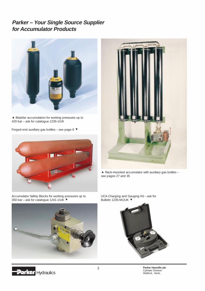
% Bladder accumulators for working pressures up to420 bar – ask for catalogue 1235-1/UK
% Rack-mounted accumulator with auxiliary gas bottles –see pages 27 and 35
Accumulator Safety Blocks for working pressures up to350 bar – ask for catalogue 1241-1/UK &
UCA Charging and Gauging Kit – ask forBulletin 1235-M1/UK &
Forged-end auxiliary gas bottles – see page 6 &
Parker – Your Single Source Supplierfor Accumulator Products
3 Parker Hannifin plcCylinder DivisionWatford, Herts.Hydraulics
Catalogue HY07-1240/UK
Introduction A, AP, B & BP SeriesPiston Accumulators
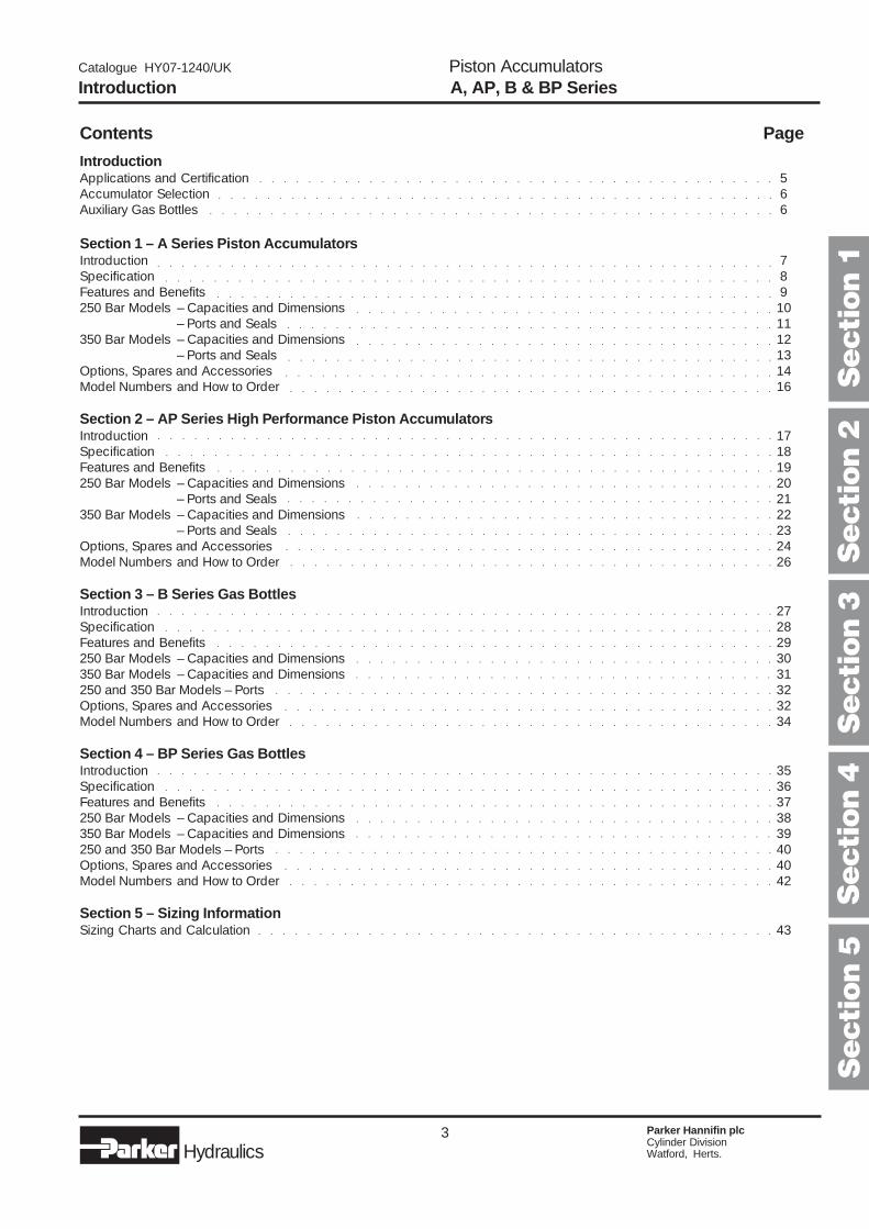
Contents Page
IntroductionApplications and Certification 5Accumulator Selection 6Auxiliary Gas Bottles 6
Section 1 – A Series Piston AccumulatorsIntroduction 7Specification 8Features and Benefits 9250 Bar Models – Capacities and Dimensions 10
– Ports and Seals 11350 Bar Models – Capacities and Dimensions 12
– Ports and Seals 13Options, Spares and Accessories 14Model Numbers and How to Order 16
Section 2 – AP Series High Performance Piston AccumulatorsIntroduction 17Specification 18Features and Benefits 19250 Bar Models – Capacities and Dimensions 20
– Ports and Seals 21350 Bar Models – Capacities and Dimensions 22
– Ports and Seals 23Options, Spares and Accessories 24Model Numbers and How to Order 26
Section 3 – B Series Gas BottlesIntroduction 27Specification 28Features and Benefits 29250 Bar Models – Capacities and Dimensions 30350 Bar Models – Capacities and Dimensions 31250 and 350 Bar Models – Ports 32Options, Spares and Accessories 32Model Numbers and How to Order 34
Section 4 – BP Series Gas BottlesIntroduction 35Specification 36Features and Benefits 37250 Bar Models – Capacities and Dimensions 38350 Bar Models – Capacities and Dimensions 39250 and 350 Bar Models – Ports 40Options, Spares and Accessories 40Model Numbers and How to Order 42
Section 5 – Sizing InformationSizing Charts and Calculation 43
○ ○ ○ ○ ○ ○ ○ ○ ○ ○ ○ ○ ○ ○ ○ ○ ○ ○ ○ ○ ○ ○ ○ ○ ○ ○ ○ ○ ○ ○ ○ ○ ○ ○ ○ ○ ○ ○ ○ ○ ○ ○ ○ ○ ○ ○ ○
○ ○ ○ ○ ○ ○ ○ ○ ○ ○ ○ ○ ○ ○ ○ ○ ○ ○ ○ ○ ○ ○ ○ ○ ○ ○ ○ ○ ○ ○ ○ ○ ○ ○ ○ ○ ○ ○ ○ ○ ○ ○ ○
○ ○ ○ ○ ○ ○ ○ ○ ○ ○ ○ ○ ○ ○ ○ ○ ○ ○ ○ ○ ○ ○ ○ ○ ○ ○ ○ ○ ○ ○ ○ ○ ○ ○ ○ ○ ○ ○ ○ ○ ○ ○ ○ ○ ○ ○ ○
○ ○ ○ ○ ○ ○ ○ ○ ○ ○ ○ ○ ○ ○ ○ ○ ○ ○ ○ ○ ○ ○ ○ ○ ○ ○ ○ ○ ○ ○ ○ ○ ○ ○ ○ ○ ○ ○ ○ ○ ○ ○ ○ ○ ○ ○ ○ ○ ○ ○ ○ ○
○ ○ ○ ○ ○ ○ ○ ○ ○ ○ ○ ○ ○ ○ ○ ○ ○ ○ ○ ○ ○ ○ ○ ○ ○ ○ ○ ○ ○ ○ ○ ○ ○ ○ ○ ○ ○ ○ ○ ○ ○ ○ ○ ○ ○ ○ ○ ○ ○ ○ ○
○ ○ ○ ○ ○ ○ ○ ○ ○ ○ ○ ○ ○ ○ ○ ○ ○ ○ ○ ○ ○ ○ ○ ○ ○ ○ ○ ○ ○ ○ ○ ○ ○ ○ ○ ○ ○ ○ ○ ○ ○ ○ ○ ○ ○ ○ ○
○ ○ ○ ○ ○ ○ ○ ○ ○ ○ ○ ○ ○ ○ ○ ○ ○ ○ ○ ○ ○ ○ ○ ○ ○ ○ ○ ○ ○ ○ ○ ○ ○ ○ ○
○ ○ ○ ○ ○ ○ ○ ○ ○ ○ ○ ○ ○ ○ ○ ○ ○ ○ ○ ○ ○ ○ ○ ○ ○ ○ ○ ○ ○ ○ ○ ○ ○ ○ ○ ○ ○ ○ ○ ○ ○
○ ○ ○ ○ ○ ○ ○ ○ ○ ○ ○ ○ ○ ○ ○ ○ ○ ○ ○ ○ ○ ○ ○ ○ ○ ○ ○ ○ ○ ○ ○ ○ ○ ○ ○
○ ○ ○ ○ ○ ○ ○ ○ ○ ○ ○ ○ ○ ○ ○ ○ ○ ○ ○ ○ ○ ○ ○ ○ ○ ○ ○ ○ ○ ○ ○ ○ ○ ○ ○ ○ ○ ○ ○ ○ ○
○ ○ ○ ○ ○ ○ ○ ○ ○ ○ ○ ○ ○ ○ ○ ○ ○ ○ ○ ○ ○ ○ ○ ○ ○ ○ ○ ○ ○ ○ ○ ○ ○ ○ ○ ○ ○ ○ ○ ○ ○
○ ○ ○ ○ ○ ○ ○ ○ ○ ○ ○ ○ ○ ○ ○ ○ ○ ○ ○ ○ ○ ○ ○ ○ ○ ○ ○ ○ ○ ○ ○ ○ ○ ○ ○ ○ ○ ○ ○ ○ ○
○ ○ ○ ○ ○ ○ ○ ○ ○ ○ ○ ○ ○ ○ ○ ○ ○ ○ ○ ○ ○ ○ ○ ○ ○ ○ ○ ○ ○ ○ ○ ○ ○ ○ ○ ○ ○ ○ ○ ○ ○ ○ ○ ○ ○ ○ ○ ○ ○ ○ ○ ○
○ ○ ○ ○ ○ ○ ○ ○ ○ ○ ○ ○ ○ ○ ○ ○ ○ ○ ○ ○ ○ ○ ○ ○ ○ ○ ○ ○ ○ ○ ○ ○ ○ ○ ○ ○ ○ ○ ○ ○ ○ ○ ○ ○ ○ ○ ○ ○ ○ ○ ○
○ ○ ○ ○ ○ ○ ○ ○ ○ ○ ○ ○ ○ ○ ○ ○ ○ ○ ○ ○ ○ ○ ○ ○ ○ ○ ○ ○ ○ ○ ○ ○ ○ ○ ○ ○ ○ ○ ○ ○ ○ ○ ○ ○ ○ ○ ○
○ ○ ○ ○ ○ ○ ○ ○ ○ ○ ○ ○ ○ ○ ○ ○ ○ ○ ○ ○ ○ ○ ○ ○ ○ ○ ○ ○ ○ ○ ○ ○ ○ ○ ○
○ ○ ○ ○ ○ ○ ○ ○ ○ ○ ○ ○ ○ ○ ○ ○ ○ ○ ○ ○ ○ ○ ○ ○ ○ ○ ○ ○ ○ ○ ○ ○ ○ ○ ○ ○ ○ ○ ○ ○ ○ ○
○ ○ ○ ○ ○ ○ ○ ○ ○ ○ ○ ○ ○ ○ ○ ○ ○ ○ ○ ○ ○ ○ ○ ○ ○ ○ ○ ○ ○ ○ ○ ○ ○ ○ ○ ○ ○ ○ ○ ○ ○
○ ○ ○ ○ ○ ○ ○ ○ ○ ○ ○ ○ ○ ○ ○ ○ ○ ○ ○ ○ ○ ○ ○ ○ ○ ○ ○ ○ ○ ○ ○ ○ ○ ○ ○ ○ ○ ○ ○ ○ ○
○ ○ ○ ○ ○ ○ ○ ○ ○ ○ ○ ○ ○ ○ ○ ○ ○ ○ ○ ○ ○ ○ ○ ○ ○ ○ ○ ○ ○ ○ ○ ○ ○ ○ ○
○ ○ ○ ○ ○ ○ ○ ○ ○ ○ ○ ○ ○ ○ ○ ○ ○ ○ ○ ○ ○ ○ ○ ○ ○ ○ ○ ○ ○ ○ ○ ○ ○ ○ ○ ○ ○ ○ ○ ○ ○ ○ ○
Secti
on 1
Secti
on 3
Secti
on 4
Secti
on 2
Secti
on 5
4 Parker Hannifin plcCylinder DivisionWatford, Herts.Hydraulics
Catalogue HY07-1240/UK
Introduction
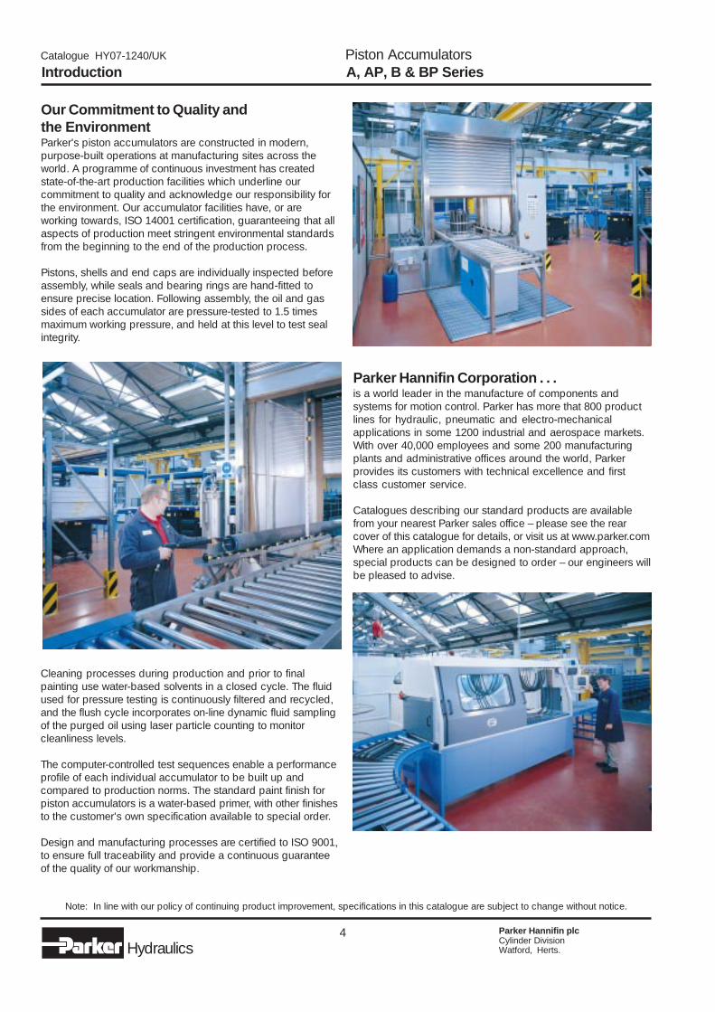
Our Commitment to Quality andthe EnvironmentParker's piston accumulators are constructed in modern,purpose-built operations at manufacturing sites across theworld. A programme of continuous investment has createdstate-of-the-art production facilities which underline ourcommitment to quality and acknowledge our responsibility forthe environment. Our accumulator facilities have, or areworking towards, ISO 14001 certification, guaranteeing that allaspects of production meet stringent environmental standardsfrom the beginning to the end of the production process.
Pistons, shells and end caps are individually inspected beforeassembly, while seals and bearing rings are hand-fitted toensure precise location. Following assembly, the oil and gassides of each accumulator are pressure-tested to 1.5 timesmaximum working pressure, and held at this level to test sealintegrity.
Note: In line with our policy of continuing product improvement, specifications in this catalogue are subject to change without notice.
A, AP, B & BP SeriesPiston Accumulators
Cleaning processes during production and prior to finalpainting use water-based solvents in a closed cycle. The fluidused for pressure testing is continuously filtered and recycled,and the flush cycle incorporates on-line dynamic fluid samplingof the purged oil using laser particle counting to monitorcleanliness levels.
The computer-controlled test sequences enable a performanceprofile of each individual accumulator to be built up andcompared to production norms. The standard paint finish forpiston accumulators is a water-based primer, with other finishesto the customer's own specification available to special order.
Design and manufacturing processes are certified to ISO 9001,to ensure full traceability and provide a continuous guaranteeof the quality of our workmanship.
Parker Hannifin Corporation . . .is a world leader in the manufacture of components andsystems for motion control. Parker has more that 800 productlines for hydraulic, pneumatic and electro-mechanicalapplications in some 1200 industrial and aerospace markets.With over 40,000 employees and some 200 manufacturingplants and administrative offices around the world, Parkerprovides its customers with technical excellence and firstclass customer service.
Catalogues describing our standard products are availablefrom your nearest Parker sales office – please see the rearcover of this catalogue for details, or visit us at www.parker.comWhere an application demands a non-standard approach,special products can be designed to order – our engineers willbe pleased to advise.
5 Parker Hannifin plcCylinder DivisionWatford, Herts.Hydraulics
Catalogue HY07-1240/UK
Applications & Certification
Hydro-Pneumatic Piston AccumulatorsParker's piston accumulators provide a means of regulatingand optimizing the performance of a hydraulic system. They areused in a wide range of industrial and mobile applications toreduce energy consumption, protect system components andprolong equipment life, reducing downtime and maintenancerequirements. Their simple, compact design ensures dependableperformance with maximum efficiency and service life.
Why use a Piston Accumulator?� Provides a practical and cost effective method of delivering
large volumes of fluid at high speed.� Provides an auxiliary power source by storing power for use
during peak demands. The resulting smaller pumps, motorsand reservoirs reduce installation and operating costs.
� Protects hydraulic systems and components from damagedue to thermal expansion and contraction in a closed system.
� Compensates for changes in fluid volume to maintain apositive pressure.
� Reduces costly damage to hoses, fittings and gauges byabsorbing hydraulic line shocks.
� Progressive failure mode protects operators and equipmentin safety-critical applications.
� Supplies emergency fail-safe power to complete a worksafety cycle in the event of pump or electrical failure.
� Maintains high pressure for long periods while preventingoil overheating, reducing pump wear and saving energy.
� Can be mounted in any attitude without loss of performance.
Typical Applications Include . . .� Die casting and injection moulding – providing high working
pressure with instantaneous flow rates during rapid cycling.� Machine tools – to maintain pressure and reduce pump size.� Piston and diaphragm pumps – reducing pump pulsations.� Hydraulic press operation – providing the high flow rates
necessary for rapid pressure rise.� Offshore applications – as a source of emergency power
for safety and shut-down systems.� Winches – maintaining line tension.� Paper-making machinery – maintaining guide and backing
roller position and pre-load.
CertificationAccumulators and gas bottles are pressure vessels which aresubject to the safety laws and regulations of the country in whichthey are operated. In addition, other industry-specific regulationsmay apply in applications such as shipbuilding, aviation etc.
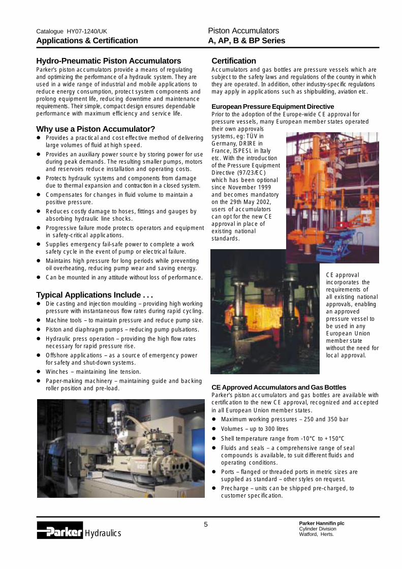
European Pressure Equipment DirectivePrior to the adoption of the Europe-wide CE approval forpressure vessels, many European member states operatedtheir own approvalssystems, eg: TÜV inGermany, DRIRE inFrance, ISPESL in Italyetc. With the introductionof the Pressure EquipmentDirective (97/23/EC)which has been optionalsince November 1999and becomes mandatoryon the 29th May 2002,users of accumulatorscan opt for the new CEapproval in place ofexisting nationalstandards.
CE approvalincorporates therequirements ofall existing nationalapprovals, enablingan approvedpressure vessel tobe used in anyEuropean Unionmember statewithout the need forlocal approval.
CE Approved Accumulators and Gas BottlesParker's piston accumulators and gas bottles are available withcertification to the new CE approval, recognized and acceptedin all European Union member states.� Maximum working pressures – 250 and 350 bar
� Volumes – up to 300 litres
� Shell temperature range from -10°C to +150°C
� Fluids and seals – a comprehensive range of sealcompounds is available, to suit different fluids andoperating conditions.
� Ports – flanged or threaded ports in metric sizes aresupplied as standard – other styles on request.
� Precharge – units can be shipped pre-charged, tocustomer specification.
A, AP, B & BP SeriesPiston Accumulators
6 Parker Hannifin plcCylinder DivisionWatford, Herts.Hydraulics
Catalogue HY07-1240/UK
the designer. While the optimum mounting orientation isvertical, angled and horizontal mountings are permissible if thehydraulic fluid is kept clean; high levels of contaminants in thefluid can result in uneven or accelerated seal wear.
Auxiliary Gas BottlesTo enhance the versatility of Parker's piston accumulator ranges,auxiliary gas bottles are available to provide a remote source ofpre-charge pressure in situations where accumulator mountingspace is restricted. The B and BP Series gas bottles featured inSections 3 and 4 of this catalogue employ a similar threaded-endconstruction to the A and AP Series piston accumulators.
Accumulator SelectionParker offers two ranges of piston accumulators for industrialuse, the A and AP Series, to suit different application andperformance criteria. Each is described in a separate section ofthis catalogue. The table below provides a brief summary toassist in initial selection.
Selection and Optional Features A, AP, B & BP SeriesPiston Accumulators
Accumulator Selection Guide
Gas Bottle Selection Guide
In addition to the industrial piston accumulators featured in thiscatalogue, Parker also offers a comprehensive range ofbladder accumulators – see Catalogue no.1235, and pistonaccumulators for mobile applications – see Catalogue no.1245.
A Series Piston AccumulatorsThe A Series range of accumulators is designed for generalpurpose applications where piston speeds and flow rates arerelatively low, such as in power units, pressure maintenanceand damping applications. The A Series range is described inSection 1, starting on page 7.
AP Series Piston AccumulatorsThe AP Series is a range of high performance accumulatorsdesigned for demanding applications such as die-casting andplastic injection moulding, where high flow rates and pistonspeeds up to 8m/s are routinely demanded. AP Seriesaccumulators are described in Section 2, starting on page 17.
When selecting a piston accumulator, factors to be consideredshould include the following:� appropriate certification for country of final destination� maximum working pressure� fluid capacity� gas capacity� piston speed, port type and size� mounting space and orientation
In addition, the type of gas valve and its connection and therequirement for a charging and gauging kit should also beconsidered. In certain applications, the use of a safety shut-offvalve or 'safety block' is mandatory, and a suitable valveshould be incorporated into the system design, as close aspossible to the accumulator which it regulates. Parker offers arange of safety blocks for this purpose – see Catalogue no.1241.
MountingThe wide variety of lengths and bore sizes available withinParker's piston accumulator range makes this design particularlysuitable for applications where mounting space is critical. Thesame fluid capacity can be achieved from different configurationsof bore and overall length, providing exceptional versatility for
In addition, gas bottles with a forged-end construction are alsoavailable and may provide a cost-effective solution in certainapplications – please ask your local Parker sales office fordetails.
Optional FeaturesThe accumulators and gas bottles featured on the followingpages are metric-mounted products which meet European CEapprovals; A and B Series accumulators and gas bottles arealso available with inch-series mountings. On request, Parkercan also supply a range of non-standard products – pleasecontact the factory for further details.
Piston Position/Precharge Monitoring – various designs areavailable to suit different applications. Our engineers will bepleased to provide further information.
Other approvals such as TÜV, DRIRE, ISPESL etc. areavailable for use where local or non-European Union approvalsare demanded.
Special designs – for applications where a standardaccumulator or gas bottle is not suitable, our engineers will bepleased to discuss custom designs to suit your application.
Accessories – safety fuses, mounting brackets, charging andgauging kits etc.
seireS
A
PA
seireS
B
PB
dradnatSlavorppA
.xaMgnikroWerusserP
diulFyticapaC
sertil.aiDeroB ecafretnI egaP
EC 053 83-1.0 mm051-05.ni6-2
cirteMhcnI& 7
EC 053 003-6 mm063-081 cirteM 71
dradnatSlavorppA
.xaMgnikroWerusserP
saGyticapaC
sertil.aiDeroB ecafretnI egaP
EC 053 04-5.1 mm051&001.ni6&4
cirteMhcnI& 72
EC 053 223-5.8 mm063-081 cirteM 53

7 Parker Hannifin plcCylinder DivisionWatford, Herts.Hydraulics
Catalogue HY07-1240/UK
Contents250 bar piston accumulators .......................... 10350 bar piston accumulators .......................... 12
A Series Piston Accumulators� Heavy duty construction for industrial and mobile applications
� CE approved to European Standard 97/23/EC
� 250 and 350 bar working pressures
� Oil volumes from 0.1 to 38 litres
� Suitable for piston speeds up to 4m/s
� Wide range of port and seal options
� Metric and inch mounting styles
Secti
on 1
8 Parker Hannifin plcCylinder DivisionWatford, Herts.Hydraulics
Catalogue HY07-1240/UK
A Series Piston AccumulatorsParker's A Series accumulators are a compact, robust designwhich has been proven in thousands of applications worldwide.Designed for general purpose applications where pistonspeeds and flow rates are relatively low, A Series accumulatorsare ideal for applications such as power units, pressuremaintenance and damping applications. A wide range of bore/stroke combinations enables the right volume to be selected ina size that will optimise the use of available space, while metricand inch mountings and a choice of port styles simplifyconnection.
250 and 350 Bar Pressure RangesA Series industrial accumulators are available in two differentpressure ratings, to suit maximum working pressures of 250and 350 bar. The same premium quality design and technicalfeatures guarantee optimum performance and service life fromevery model, while differing wall thicknesses to suit 250 or 350bar working pressures allow the designer to specify preciselythe right performance envelope for the application.
SpecificationMax. working pressures 250 and 350 barWorking temp. range shell: -10 to +150°C (CE approved)
seals: see pages 11 and 13Fluid volumes 0.1–38 litresBore sizes 50 –150mm (nominal)Max. piston speed 4m/sPort style BSPP (standard – others on request)Gas valve 350 bar rated cored typeApproval CE (standard – others on request)
Materials� Shell – high strength steel� End caps – steel� Pistons – lightweight aluminium alloy� Piston and cap end seals – NBR (standard): other
compounds to suit application� Piston seal backup washers – PTFE� Piston bearing rings – PTFE� Gas valve assembly – stainless steel� Gas valve protector – steel� Paint finish – black primer (standard – others on request)
Custom DesignsFor unique applications and hostile environments, differentdesigns and materials can be supplied. Please contact ourengineering department to discuss custom solutions toindividual application requirements.
Available OptionsA wide variety of options is available for A Series accumulators,including:� Port styles and sizes� Seal compounds� Metric and inch mounting styles� High flow gas ports for use with remote gas storage bottles� Water service versions� Gas valves� Safety fuses� Accumulator mounting systems� Precharge/piston position sensors� Certifications to suit different market requirements
Calculating Accumulator SizeAccurate calculation of accumulator size requires many factorsto be considered – the working volume of oil, ambient andmaximum operating temperatures, the working pressure rangeetc. In addition, correction factors must be applied to allow fortemperature compensation between the ambient and gastemperatures, and the consequent effect on prechargepressure in the accumulator. Where the working cycle issufficiently rapid that no heat transfer takes place, the processis termed adiabatic. Conversely, where the process takes placeat a constant temperature, it is termed isothermal. Calculationsand sizing charts which enable the designer to compensate forthese differing conditions are shown on page 43.
FiltrationFor maximum component life, the system should be protectedfrom contamination by effective filtration. Fluid cleanlinessshould be in accordance with ISO 4406. The quality of filtersshould be in accordance with the appropriate ISO standards.
The rating of the filter media depends on the systemcomponents and the application. The minimum required forhydraulic systems should be class 19/15 to ISO 4406, whichequates to 25µ (β10�75) to ISO 4572.
SpecificationSection 1A Series Piston Accumulators
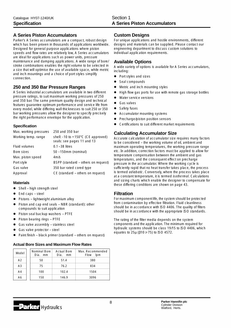
Actual Bore Sizes and Maximum Flow Rates
ledoM
2A
3A
4A
6A
eroBlanimoNmm.aiD
eroBlautcAmm.aiD
dednemmoceR.xaMmplwolF
05 4.15 083
57 2.67 438
001 4.201 4051
051 9.641 6903
9 Parker Hannifin plcCylinder DivisionWatford, Herts.Hydraulics
Catalogue HY07-1240/UK
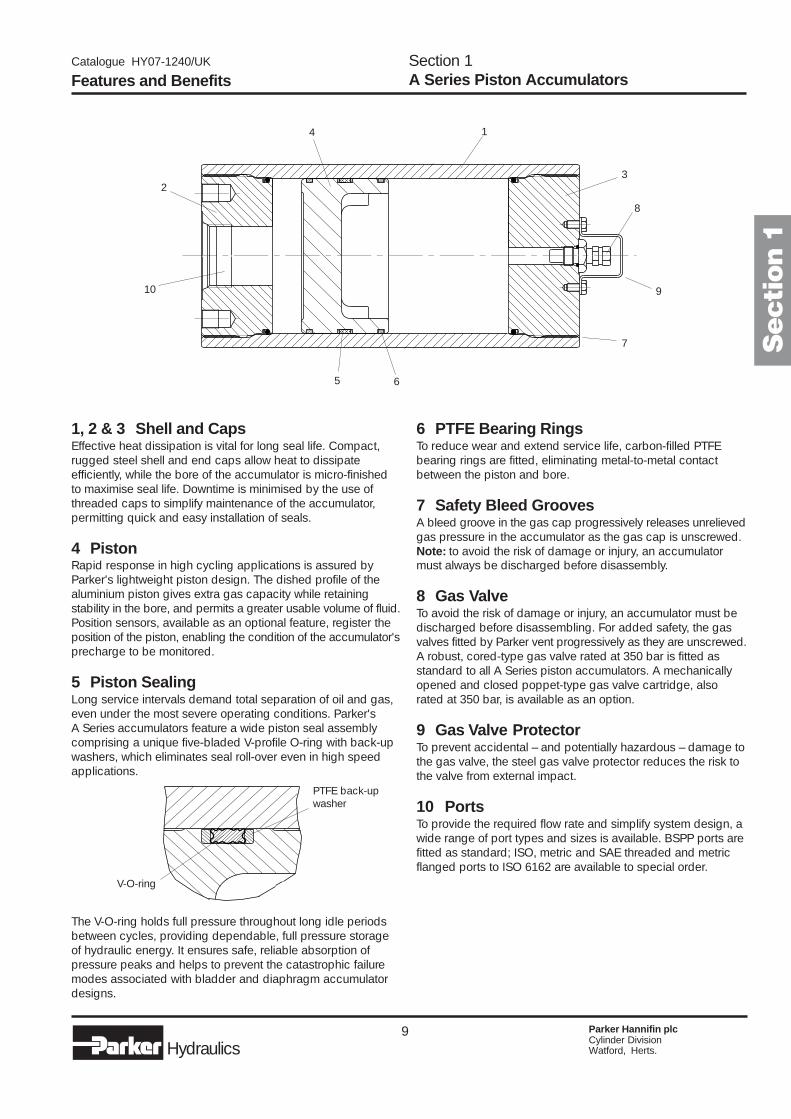
1, 2 & 3 Shell and CapsEffective heat dissipation is vital for long seal life. Compact,rugged steel shell and end caps allow heat to dissipateefficiently, while the bore of the accumulator is micro-finishedto maximise seal life. Downtime is minimised by the use ofthreaded caps to simplify maintenance of the accumulator,permitting quick and easy installation of seals.
4 PistonRapid response in high cycling applications is assured byParker's lightweight piston design. The dished profile of thealuminium piston gives extra gas capacity while retainingstability in the bore, and permits a greater usable volume of fluid.Position sensors, available as an optional feature, register theposition of the piston, enabling the condition of the accumulator'sprecharge to be monitored.
5 Piston SealingLong service intervals demand total separation of oil and gas,even under the most severe operating conditions. Parker'sA Series accumulators feature a wide piston seal assemblycomprising a unique five-bladed V-profile O-ring with back-upwashers, which eliminates seal roll-over even in high speedapplications.
6 PTFE Bearing RingsTo reduce wear and extend service life, carbon-filled PTFEbearing rings are fitted, eliminating metal-to-metal contactbetween the piston and bore.
7 Safety Bleed GroovesA bleed groove in the gas cap progressively releases unrelievedgas pressure in the accumulator as the gas cap is unscrewed.Note: to avoid the risk of damage or injury, an accumulatormust always be discharged before disassembly.
8 Gas ValveTo avoid the risk of damage or injury, an accumulator must bedischarged before disassembling. For added safety, the gasvalves fitted by Parker vent progressively as they are unscrewed.A robust, cored-type gas valve rated at 350 bar is fitted asstandard to all A Series piston accumulators. A mechanicallyopened and closed poppet-type gas valve cartridge, alsorated at 350 bar, is available as an option.
9 Gas Valve ProtectorTo prevent accidental – and potentially hazardous – damage tothe gas valve, the steel gas valve protector reduces the risk tothe valve from external impact.
10 PortsTo provide the required flow rate and simplify system design, awide range of port types and sizes is available. BSPP ports arefitted as standard; ISO, metric and SAE threaded and metricflanged ports to ISO 6162 are available to special order.
The V-O-ring holds full pressure throughout long idle periodsbetween cycles, providing dependable, full pressure storageof hydraulic energy. It ensures safe, reliable absorption ofpressure peaks and helps to prevent the catastrophic failuremodes associated with bladder and diaphragm accumulatordesigns.
Features and BenefitsSection 1A Series Piston Accumulators
V-O-ring
PTFE back-upwasher
Secti
on 1
1
23
4
5 6
7
8
910
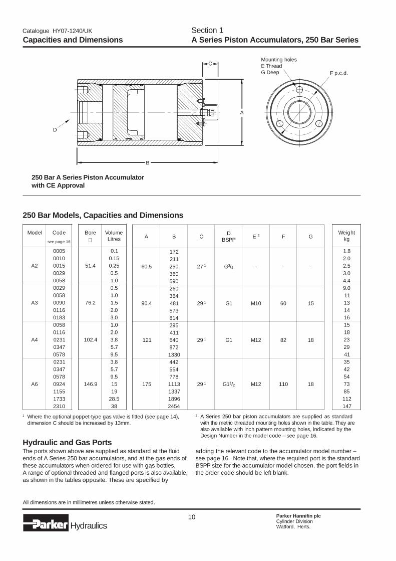
10 Parker Hannifin plcCylinder DivisionWatford, Herts.Hydraulics
Catalogue HY07-1240/UK
250 Bar A Series Piston Accumulatorwith CE Approval
250 Bar Models, Capacities and Dimensions
All dimensions are in millimetres unless otherwise stated.
Hydraulic and Gas PortsThe ports shown above are supplied as standard at the fluidends of A Series 250 bar accumulators, and at the gas ends ofthese accumulators when ordered for use with gas bottles.A range of optional threaded and flanged ports is also available,as shown in the tables opposite. These are specified by
2 A Series 250 bar piston accumulators are supplied as standardwith the metric threaded mounting holes shown in the table. They arealso available with inch pattern mounting holes, indicated by theDesign Number in the model code – see page 16.
adding the relevant code to the accumulator model number –see page 16. Note that, where the required port is the standardBSPP size for the accumulator model chosen, the port fields inthe order code should be left blank.
Capacities and DimensionsSection 1A Series Piston Accumulators, 250 Bar Series
D
B
A
CMounting holesE ThreadG Deep F p.c.d.
1 Where the optional poppet-type gas valve is fitted (see page 14),dimension C should be increased by 13mm.
ledoM edoC
61egapees
2A
50000100510092008500
3A
92008500090061103810
4A
85006110132074308750
6A
1320743087504290551133710132
eroB emuloVsertiL∅
4.15
1.051.052.0
5.00.1
2.67
5.00.15.10.20.3
4.201
0.10.28.37.55.9
9.641
8.37.55.951915.82
83
A B C DPPSB E 2 F G
5.06
271
72 1 G3/4 - - -112052063095
4.09
062
92 1 1G 01M 06 51463184375418
121
592
92 1 1G 21M 28 811140462780331
571
244
92 1 1G 1/2 21M 011 81
4558773111733169814542
thgieWgk
8.10.25.20.34.40.91131416151813292145324453758211741
11 Parker Hannifin plcCylinder DivisionWatford, Herts.Hydraulics
Catalogue HY07-1240/UK
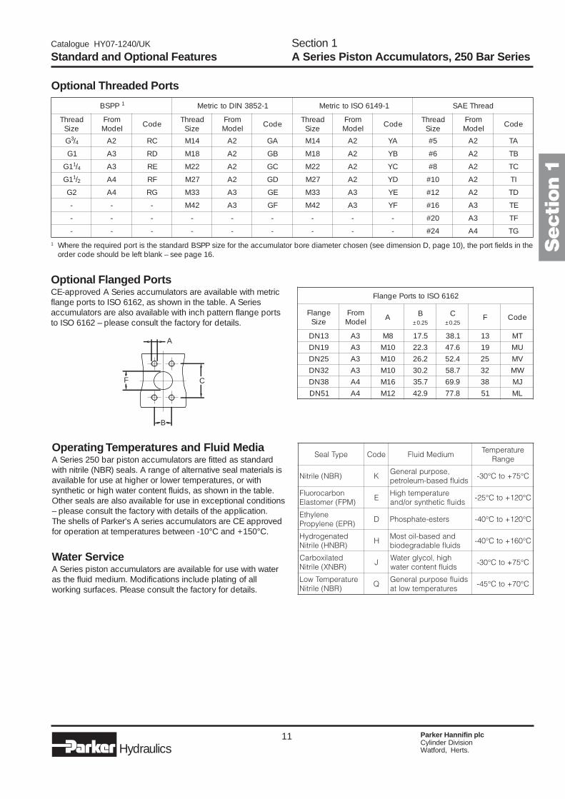
Optional Threaded Ports
Optional Flanged PortsCE-approved A Series accumulators are available with metricflange ports to ISO 6162, as shown in the table. A Seriesaccumulators are also available with inch pattern flange portsto ISO 6162 – please consult the factory for details.
1 Where the required port is the standard BSPP size for the accumulator bore diameter chosen (see dimension D, page 10), the port fields in theorder code should be left blank – see page 16.
Operating Temperatures and Fluid MediaA Series 250 bar piston accumulators are fitted as standardwith nitrile (NBR) seals. A range of alternative seal materials isavailable for use at higher or lower temperatures, or withsynthetic or high water content fluids, as shown in the table.Other seals are also available for use in exceptional conditions– please consult the factory with details of the application.The shells of Parker's A series accumulators are CE approvedfor operation at temperatures between -10°C and +150°C.
Water ServiceA Series piston accumulators are available for use with wateras the fluid medium. Modifications include plating of allworking surfaces. Please consult the factory for details.
Section 1A Series Piston Accumulators, 250 Bar SeriesStandard and Optional Features
A
F
B
C
Secti
on 1
PPSB 1 1-2583NIDotcirteM 1-9416OSIotcirteM daerhTEAS
daerhTeziS
morFledoM edoC daerhT
eziSmorF
ledoM edoC daerhTeziS
morFledoM edoC daerhT
eziSmorF
ledoM edoC
G3/4 2A CR 41M 2A AG 41M 2A AY 5# 2A AT
1G 3A DR 81M 2A BG 81M 2A BY 6# 2A BT
1G 1/4 3A ER 22M 2A CG 22M 2A CY 8# 2A CT
1G 1/2 4A FR 72M 2A DG 72M 2A DY 01# 2A IT
2G 4A GR 33M 3A EG 33M 3A EY 21# 2A DT
- - - 24M 3A FG 24M 3A FY 61# 3A ET
- - - - - - - - - 02# 3A FT
- - - - - - - - - 42# 4A GT
2616OSIotstroPegnalF
egnalFeziS
morFledoM A B C F edoC
52.0± 52.0±
31ND 3A 8M 5.71 1.83 31 TM91ND 3A 01M 3.22 6.74 91 UM52ND 3A 01M 2.62 4.25 52 VM23ND 3A 01M 2.03 7.85 23 WM83ND 4A 61M 7.53 9.96 83 JM15ND 4A 21M 9.24 8.77 15 LM
epyTlaeS edoC muideMdiulFerutarepmeT
egnaR
)RBN(elirtiN K,esopruplareneG
sdiulfdesab-muelortepC°57+otC°03-
nobracoroulF)MPF(remotsalE
EerutarepmethgiH
sdiulfcitehtnysro/dnaC°021+otC°52-
enelyhtE)RPE(enelyporP
D sretse-etahpsohP C°021+otC°04-
detanegordyH)RBNH(elirtiN
Hdnadesab-liotsoM
sdiulfelbadargedoibC°061+otC°04-
detalixobraC)RBNX(elirtiN
Jhgih,locylgretaW
sdiulftnetnocretawC°57+otC°03-
erutarepmeTwoL)RBN(elirtiN
QsdiulfesopruplareneG
serutarepmetwoltaC°07+otC°54-
12 Parker Hannifin plcCylinder DivisionWatford, Herts.Hydraulics
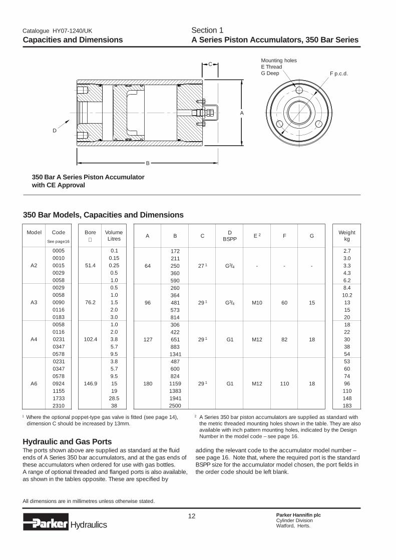
Catalogue HY07-1240/UK
350 Bar A Series Piston Accumulatorwith CE Approval
350 Bar Models, Capacities and Dimensions
All dimensions are in millimetres unless otherwise stated.
Capacities and DimensionsSection 1A Series Piston Accumulators, 350 Bar Series
Hydraulic and Gas PortsThe ports shown above are supplied as standard at the fluidends of A Series 350 bar accumulators, and at the gas ends ofthese accumulators when ordered for use with gas bottles.A range of optional threaded and flanged ports is also available,as shown in the tables opposite. These are specified by
2 A Series 350 bar piston accumulators are supplied as standard withthe metric threaded mounting holes shown in the table. They are alsoavailable with inch pattern mounting holes, indicated by the DesignNumber in the model code – see page 16.
adding the relevant code to the accumulator model number –see page 16. Note that, where the required port is the standardBSPP size for the accumulator model chosen, the port fields inthe order code should be left blank.
D
B
A
CMounting holesE ThreadG Deep F p.c.d.
1 Where the optional poppet-type gas valve is fitted (see page 14),dimension C should be increased by 13mm.
ledoM edoC
61egapeeS
2A
50000100510092008500
3A
92008500090061103810
4A
85006110132074308750
6A
1320743087504290551133710132
eroB emuloVsertiL∅
4.15
1.051.052.0
5.00.1
2.67
5.00.15.10.20.3
4.201
0.10.28.37.55.9
9.641
8.37.55.951915.82
83
A B C DPPSB E 2 F G
46
271
72 1 G3/4 - - -112052063095
69
062
92 1 G3/4 01M 06 51463184375418
721
603
92 1 1G 21M 28 812241563881431
081
784
92 1 1G 21M 011 81
0064289511383114910052
thgieWgk
7.20.33.33.42.64.82.01
315102812203834535064769011841381
13 Parker Hannifin plcCylinder DivisionWatford, Herts.Hydraulics
Catalogue HY07-1240/UK
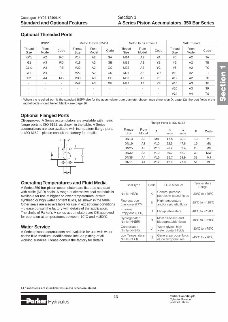
Optional Threaded Ports
Optional Flanged PortsCE-approved A Series accumulators are available with metricflange ports to ISO 6162, as shown in the table. A Seriesaccumulators are also available with inch pattern flange portsto ISO 6162 – please consult the factory for details.
1 Where the required port is the standard BSPP size for the accumulator bore diameter chosen (see dimension D, page 12), the port fields in themodel code should be left blank – see page 16.
Operating Temperatures and Fluid MediaA Series 350 bar piston accumulators are fitted as standardwith nitrile (NBR) seals. A range of alternative seal materials isavailable for use at higher or lower temperatures, or withsynthetic or high water content fluids, as shown in the table.Other seals are also available for use in exceptional conditions– please consult the factory with details of the application.The shells of Parker's A series accumulators are CE approvedfor operation at temperatures between -10°C and +150°C.
Water ServiceA Series piston accumulators are available for use with wateras the fluid medium. Modifications include plating of allworking surfaces. Please consult the factory for details.
Standard and Optional FeaturesSection 1A Series Piston Accumulators, 350 Bar Series
All dimensions are in millimetres unless otherwise stated.
A
B
F C
Secti
on 1
PPSB 1 1-2583NIDotcirteM 1-9416OSIotcirteM daerhTEAS
daerhTeziS
morFledoM edoC daerhT
eziSmorF
ledoM edoC daerhTeziS
morFledoM edoC daerhT
eziSmorF
ledoM edoC
G3/4 2A CR 41M 2A AG 41M 2A AY 5# 2A AT
1G 3A DR 81M 2A BG 81M 2A BY 6# 2A BT
1G 1/4 3A ER 22M 2A CG 22M 2A CY 8# 2A CT
1G 1/2 4A FR 72M 2A DG 72M 2A DY 01# 2A IT
2G 4A GR 33M 3A EG 33M 3A EY 21# 2A DT
- - - 24M 3A FG 24M 3A FY 61# 3A ET
- - - - - - - - - 02# 3A FT
- - - - - - - - - 42# 4A GT
2616OSIotstroPegnalF
egnalFeziS
morFledoM A B C F edoC
52.0± 52.0±
31ND 3A 8M 5.71 1.83 31 TM91ND 3A 01M 3.22 6.74 91 UM52ND 3A 01M 2.62 4.25 52 VM23ND 3A 01M 2.03 7.85 23 WM83ND 4A 61M 7.53 9.96 83 JM15ND 4A 21M 9.24 8.77 15 LM
epyTlaeS edoC muideMdiulFerutarepmeT
egnaR
)RBN(elirtiN K,esopruplareneG
sdiulfdesab-muelortepC°57+otC°03-
nobracoroulF)MPF(remotsalE
EerutarepmethgiH
sdiulfcitehtnysro/dnaC°021+otC°52-
enelyhtE)RPE(enelyporP
D sretse-etahpsohP C°021+otC°04-
detanegordyH)RBNH(elirtiN
Hdnadesab-liotsoM
sdiulfelbadargedoibC°061+otC°04-
detalixobraC)RBNX(elirtiN
Jhgih,locylgretaW
sdiulftnetnocretawC°57+otC°03-
erutarepmeTwoL)RBN(elirtiN
QsdiulfesopruplareneG
serutarepmetwoltaC°07+otC°54-
14 Parker Hannifin plcCylinder DivisionWatford, Herts.Hydraulics
Catalogue HY07-1240/UK
Options, Spares and Accessories
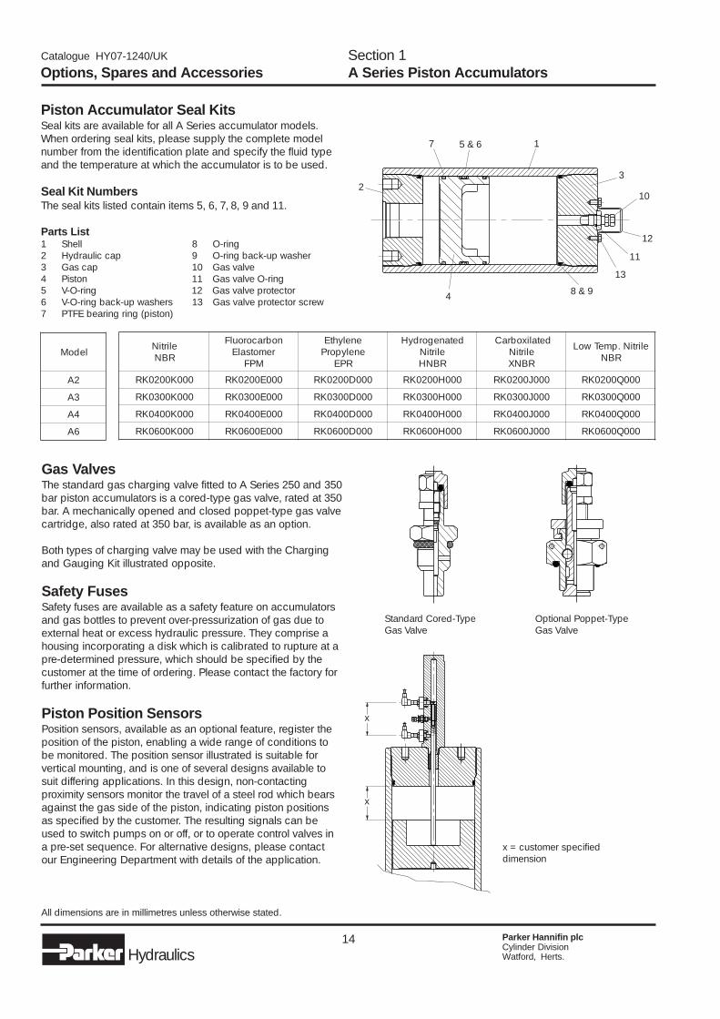
Piston Accumulator Seal KitsSeal kits are available for all A Series accumulator models.When ordering seal kits, please supply the complete modelnumber from the identification plate and specify the fluid typeand the temperature at which the accumulator is to be used.
Seal Kit NumbersThe seal kits listed contain items 5, 6, 7, 8, 9 and 11.
Parts List1 Shell 8 O-ring2 Hydraulic cap 9 O-ring back-up washer3 Gas cap 10 Gas valve4 Piston 11 Gas valve O-ring5 V-O-ring 12 Gas valve protector6 V-O-ring back-up washers 13 Gas valve protector screw7 PTFE bearing ring (piston)
All dimensions are in millimetres unless otherwise stated.
Section 1A Series Piston Accumulators
Gas ValvesThe standard gas charging valve fitted to A Series 250 and 350bar piston accumulators is a cored-type gas valve, rated at 350bar. A mechanically opened and closed poppet-type gas valvecartridge, also rated at 350 bar, is available as an option.
Both types of charging valve may be used with the Chargingand Gauging Kit illustrated opposite.
Safety FusesSafety fuses are available as a safety feature on accumulatorsand gas bottles to prevent over-pressurization of gas due toexternal heat or excess hydraulic pressure. They comprise ahousing incorporating a disk which is calibrated to rupture at apre-determined pressure, which should be specified by thecustomer at the time of ordering. Please contact the factory forfurther information.
Piston Position SensorsPosition sensors, available as an optional feature, register theposition of the piston, enabling a wide range of conditions tobe monitored. The position sensor illustrated is suitable forvertical mounting, and is one of several designs available tosuit differing applications. In this design, non-contactingproximity sensors monitor the travel of a steel rod which bearsagainst the gas side of the piston, indicating piston positionsas specified by the customer. The resulting signals can beused to switch pumps on or off, or to operate control valves ina pre-set sequence. For alternative designs, please contactour Engineering Department with details of the application.
Standard Cored-TypeGas Valve
Optional Poppet-TypeGas Valve
x = customer specifieddimension
x
x
1
23
4
5 & 67
8 & 9
10
12
13
11
ledoM
2A
3A
4A
6A
elirtiNRBN
nobracoroulFremotsalE
MPF
enelyhtEenelyporP
RPE
detanegordyHelirtiNRBNH
detalixobraCelirtiNRBNX
elirtiN.pmeTwoLRBN
000K0020KR 000E0020KR 000D0020KR 000H0020KR 000J0020KR 000Q0020KR
000K0030KR 000E0030KR 000D0030KR 000H0030KR 000J0030KR 000Q0030KR
000K0040KR 000E0040KR 000D0040KR 000H0040KR 000J0040KR 000Q0040KR
000K0060KR 000E0060KR 000D0060KR 000H0060KR 000J0060KR 000Q0060KR
15 Parker Hannifin plcCylinder DivisionWatford, Herts.Hydraulics
Catalogue HY07-1240/UK
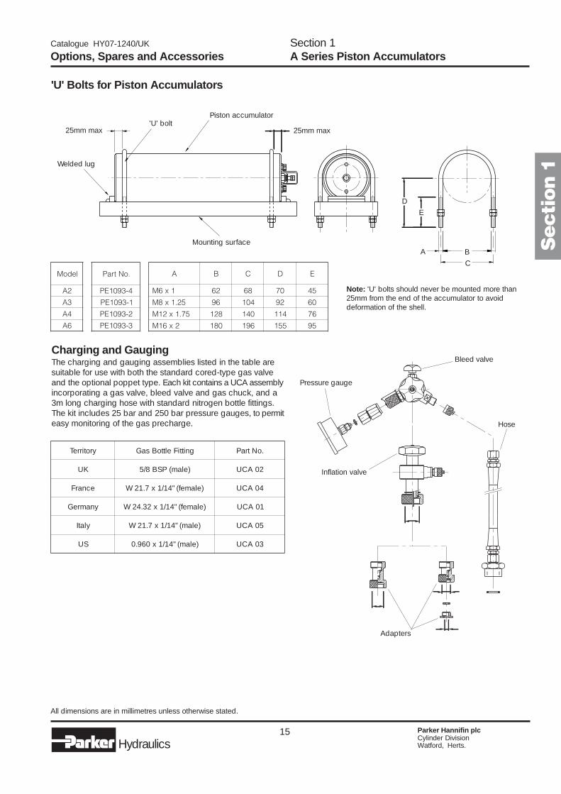
Charging and GaugingThe charging and gauging assemblies listed in the table aresuitable for use with both the standard cored-type gas valveand the optional poppet type. Each kit contains a UCA assemblyincorporating a gas valve, bleed valve and gas chuck, and a3m long charging hose with standard nitrogen bottle fittings.The kit includes 25 bar and 250 bar pressure gauges, to permiteasy monitoring of the gas precharge.
Options, Spares and AccessoriesSection 1A Series Piston Accumulators
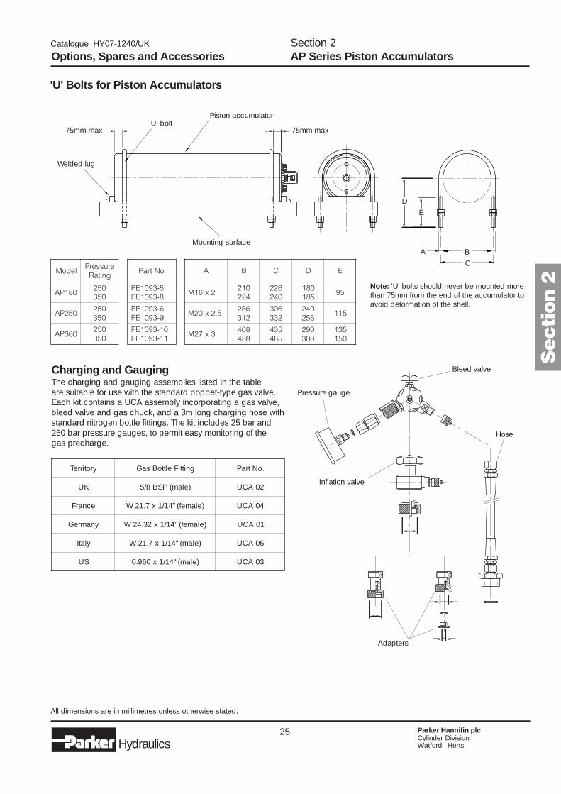
'U' Bolts for Piston Accumulators
Note: 'U' bolts should never be mounted more than25mm from the end of the accumulator to avoiddeformation of the shell.
All dimensions are in millimetres unless otherwise stated.
Inflation valve
Bleed valve
Adapters
Pressure gauge
Hose
Secti
on 1Welded lug
25mm max
Mounting surface
25mm max
Piston accumulator'U' bolt
A B
C
D
E
ledoM
2A
3A
4A
6A
.oNtraP
4-3901EP
1-3901EP
2-3901EP
3-3901EP
A B C D E
1x6M 26 86 07 54
52.1x8M 69 401 29 06
57.1x21M 821 041 411 67
2x61M 081 691 551 59
yrotirreT gnittiFelttoBsaG .oNtraP
KU )elam(PSB8/5 20ACU
ecnarF )elamef("41/1x7.12W 40ACU
ynamreG )elamef("41/1x23.42W 10ACU
ylatI )elam("41/1x7.12W 50ACU
SU )elam("41/1x069.0 30ACU

16 Parker Hannifin plcCylinder DivisionWatford, Herts.Hydraulics
Catalogue HY07-1240/UK
Hydraulic and Gas Port ModificationsFor accumulators with non-standard ports, specify special gasand/or hydraulic ports and use the appropriate port code frompages 11 or 13. A typical model number for an accumulatorwith ISO 6149 hydraulic and gas ports would be:
Model NumbersEach Parker accumulator is assigned a model number whichrepresents the features selected. To develop a model number,identify the relevant characters from the table below and enterthem in the sequence shown in the example.
Product Type A Series accumulator 7 A
Model A2 50mm bore 10-12 2A3 75mm bore 3A4 100mm bore 4A6 150mm bore 6
Approval CE approved 1 5 EType
Options Cored-type gas valve (standard) 2 14 SCored-type gas valve + water service 13, 14 WCored-type gas valve + safety fuse 14 FCored-type gas valve + water service + safety fuse 13, 14 GPoppet-type (MS) gas valve 14 MPoppet-type gas valve + water service 13, 14 LPoppet-type gas valve + safety fuse 14 PPoppet-type gas valve + water service + safety fuse 13, 14 R
Capacity 0.1 – A2 only 10, 12 0005(litres) 0.15 – A2 only 0010
0.25 – A2 only 00150.5 – A2 & A3 00291.0 – A2, A3, A4 00581.5 – A3 only 00902.0 – A3, A4 01163.0 – A3 only 01833.8 – A4, A6 02315.7 – A4, A6 03479.5 – A4, A6 057815 – A6 only 092419 – A6 only 115528.5 – A6 only 173338 – A6 only 2310
Design 250 bar 8, 10 LPressure 3 350 bar 8, 12 H
Design Metric mounting + BSPP ports (standard) 10-13 2Number Inch mounting + SAE ports 10-13 1
Special ports 11, 13 3Specials (Parker assigned design number) – ###
Seal Nitrile (NBR) 11, 13 KCompound Fluorocarbon Elastomer (FPM) 11, 13 E
Hydrogenated nitrile (HNBR) 11, 13 HEthylene Propylene (EPR) 11, 13 DCarboxilated nitrile (XNBR) 11, 13 JLow temperature nitrile 11, 13 QSpecial – please specify 11, 13 S
Hydraulic port specification See pages 10-13
Gas port specification (no gas valve supplied) See pages 10-13
Feature Description Page SymbolExample
A 3 E S 0090 L 2 K – – / – –
How to OrderSection 1A Series Piston Accumulators
1 Other approvals are available to order – please consult the factory.2 Where a gas port is specified, no gas valve will be supplied.3 For other pressure ratings, please consult the factory.
A 4 E S 3810 L 2 K EY/EY

17 Parker Hannifin plcCylinder DivisionWatford, Herts.Hydraulics
Catalogue HY07-1240/UK
Contents250 bar piston accumulators .......................... 20350 bar piston accumulators .......................... 22
AP Series High PerformancePiston Accumulators
� Premium quality construction for demanding industrial applications
� CE approved to European Standard 97/23/EC
� 250 and 350 bar working pressures
� Oil volumes from 6.0 to 300 litres
� High performance sealing systemsfor piston speeds up to 8m/s
� Flow rates up to 45,000 lpm
� High flow ports for rapidcycling performance
Secti
on 2

18 Parker Hannifin plcCylinder DivisionWatford, Herts.Hydraulics
Catalogue HY07-1240/UK
AP Series Piston AccumulatorsParker's AP Series accumulators are a premium specificationproduct designed for use in high performance applicationssuch as die casting and plastic injection moulding, wherelarge volumes of fluid have to be displaced at high speed.Special multi-element sealing systems have been developedto combine good servo application and load holding propertieswith the wear characteristics required to withstand continuoususe at piston speeds of up to 8m/s.
A wide range of bore/stroke combinations enables anaccumulator with the required volume to be selected in a sizethat will optimise the use of available space, while metricmountings and a choice of port styles simplify connection.Parker offers a full range of clamps to provide secure mounting.
250 and 350 Bar Pressure RangesAP Series industrial accumulators are available in two differentpressure ratings, to suit maximum working pressures of 250and 350 bar. The same premium quality design and technicalfeatures guarantee optimum performance and service life fromevery AP Series accumulator model, while differing wallthicknesses allow the designer to specify precisely the rightperformance envelope for the application.
Specifications –Max. working pressures 250 and 350 bar*Working temp. range -10 to +80°C (to +150°C on request)Fluid volumes 6.0 –300 litresBore sizes 180, 250 and 360mmMax. piston speed 8m/sPort style BSPP (standard – others on request)Seal type multi-element oil and gas seals with
twin low friction bearing ringsGas valve 350 bar rated poppet typeApproval CE (standard – others on request)
* For operation at temperatures above 80°C, please consultthe factory.
Materials� Shell – high strength steel� End caps – steel� Pistons – lightweight aluminium alloy� Cap end seals – NBR (standard): other compounds to suit
application� Piston bearing rings – filled PTFE� Piston seals – filled PTFE (standard): other compounds to
suit application� Gas valve assembly – stainless steel� Gas valve protector – steel� Paint finish – black primer, suitable for epoxy paint finishes
(standard) – other finishes on request
Custom DesignsFor unique applications and hostile environments, differentdesigns and materials can be supplied. Please contact ourengineering department to discuss custom solutions toindividual application requirements.
Available OptionsA wide variety of options is available for AP Series accumulators,including:� Port styles and sizes� Seal compounds� High flow gas ports for use with remote gas storage bottles� Water service versions� Safety fuses� Mounting systems� Precharge/piston position sensors� Certifications to suit different market requirements
Calculating Accumulator SizeAccurate calculation of accumulator size requires many factorsto be considered – the working volume of oil, ambient andmaximum operating temperatures, the working pressure rangeetc. In addition, correction factors must be applied to allow fortemperature compensation between the ambient and gastemperatures, and the consequent effect on prechargepressure in the accumulator. Where the working cycle issufficiently rapid that no heat transfer takes place, the processis termed adiabatic. Conversely, where the process takesplace at a constant temperature, it is termed isothermal.Calculations which enable the designer to compensate forthese differing conditions are shown on page 43.
FiltrationFor maximum component life, the system should be protectedfrom contamination by effective filtration. Fluid cleanlinessshould be in accordance with ISO 4406. The quality of filtersshould be in accordance with the appropriate ISO standards.
The rating of the filter media depends on the systemcomponents and the application. The minimum required forhydraulic systems should be class 19/15 to ISO 4406, whichequates to 25µ (β10�75) to ISO 4572.
SpecificationSection 2AP Series Piston Accumulators
Maximum Flow Rates
ledoM
081PA
052PA
063PA
.aiDeroBmm
wolFdednemmoceR.xaMmpl
081 000,21
052 000,32
063 000,54
19 Parker Hannifin plcCylinder DivisionWatford, Herts.Hydraulics
Catalogue HY07-1240/UK
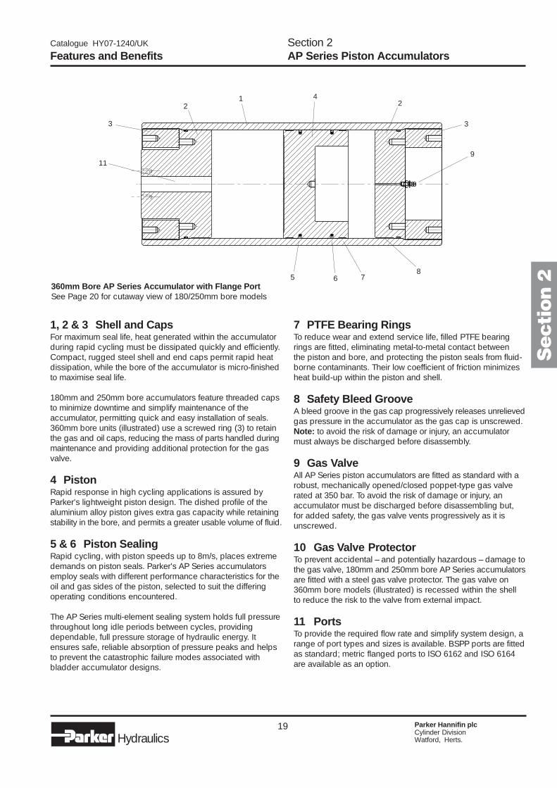
1, 2 & 3 Shell and CapsFor maximum seal life, heat generated within the accumulatorduring rapid cycling must be dissipated quickly and efficiently.Compact, rugged steel shell and end caps permit rapid heatdissipation, while the bore of the accumulator is micro-finishedto maximise seal life.
180mm and 250mm bore accumulators feature threaded capsto minimize downtime and simplify maintenance of theaccumulator, permitting quick and easy installation of seals.360mm bore units (illustrated) use a screwed ring (3) to retainthe gas and oil caps, reducing the mass of parts handled duringmaintenance and providing additional protection for the gasvalve.
4 PistonRapid response in high cycling applications is assured byParker's lightweight piston design. The dished profile of thealuminium alloy piston gives extra gas capacity while retainingstability in the bore, and permits a greater usable volume of fluid.
5 & 6 Piston SealingRapid cycling, with piston speeds up to 8m/s, places extremedemands on piston seals. Parker's AP Series accumulatorsemploy seals with different performance characteristics for theoil and gas sides of the piston, selected to suit the differingoperating conditions encountered.
The AP Series multi-element sealing system holds full pressurethroughout long idle periods between cycles, providingdependable, full pressure storage of hydraulic energy. Itensures safe, reliable absorption of pressure peaks and helpsto prevent the catastrophic failure modes associated withbladder accumulator designs.
Features and BenefitsSection 2AP Series Piston Accumulators
7 PTFE Bearing RingsTo reduce wear and extend service life, filled PTFE bearingrings are fitted, eliminating metal-to-metal contact betweenthe piston and bore, and protecting the piston seals from fluid-borne contaminants. Their low coefficient of friction minimizesheat build-up within the piston and shell.
8 Safety Bleed GrooveA bleed groove in the gas cap progressively releases unrelievedgas pressure in the accumulator as the gas cap is unscrewed.Note: to avoid the risk of damage or injury, an accumulatormust always be discharged before disassembly.
9 Gas ValveAll AP Series piston accumulators are fitted as standard with arobust, mechanically opened/closed poppet-type gas valverated at 350 bar. To avoid the risk of damage or injury, anaccumulator must be discharged before disassembling but,for added safety, the gas valve vents progressively as it isunscrewed.
10 Gas Valve ProtectorTo prevent accidental – and potentially hazardous – damage tothe gas valve, 180mm and 250mm bore AP Series accumulatorsare fitted with a steel gas valve protector. The gas valve on360mm bore models (illustrated) is recessed within the shellto reduce the risk to the valve from external impact.
11 PortsTo provide the required flow rate and simplify system design, arange of port types and sizes is available. BSPP ports are fittedas standard; metric flanged ports to ISO 6162 and ISO 6164are available as an option.
360mm Bore AP Series Accumulator with Flange PortSee Page 20 for cutaway view of 180/250mm bore models
12 2
68
9
4
11
5 7
Secti
on 2
33
20 Parker Hannifin plcCylinder DivisionWatford, Herts.Hydraulics
Catalogue HY07-1240/UK
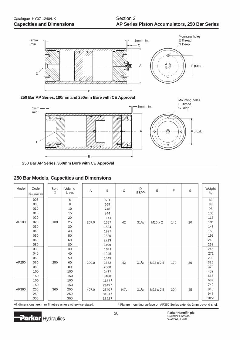
250 Bar Models, Capacities and Dimensions
All dimensions are in millimetres unless otherwise stated.
Capacities and DimensionsSection 2AP Series Piston Accumulators, 250 Bar Series
1 Flange mounting surface on AP360 Series extends 2mm beyond shell.
D
A
C
Mounting holesE ThreadG Deep
250 Bar AP Series, 180mm and 250mm Bore with CE Approval
250 Bar AP Series, 360mm Bore with CE Approval
B
2mmmin.
2mm min.
F p.c.d.
1mmmin.
D
B
1mm min.
A
Mounting holesE ThreadG Deep
F p.c.d.
ledoM edoC
62egapeeS
081PA
600800010510020520030040050060080
052PA
030040050060080001051
063PA
001051002052003
eroB∅
emuloVsertiL
081
68015102520304050608
052
0304050608001051
063
001051002052003
thgieWgk
3888396018111313418613918128625421728925239732346659362475488491501
A B C DPPSB E F G
0.702
195
24 1G 1/2 2x61M 041 02
9668474491411733143517291023231729943
0.092
1401
24 1G 1/2 5.2x22M 071 03
542194412561060276426843
0.704
7561 1
A/N 1G 1/2 5.2x22M 403 549412 1
0462 1
1313 1
2263 1
21 Parker Hannifin plcCylinder DivisionWatford, Herts.Hydraulics
Catalogue HY07-1240/UK
Optional Flanged Ports
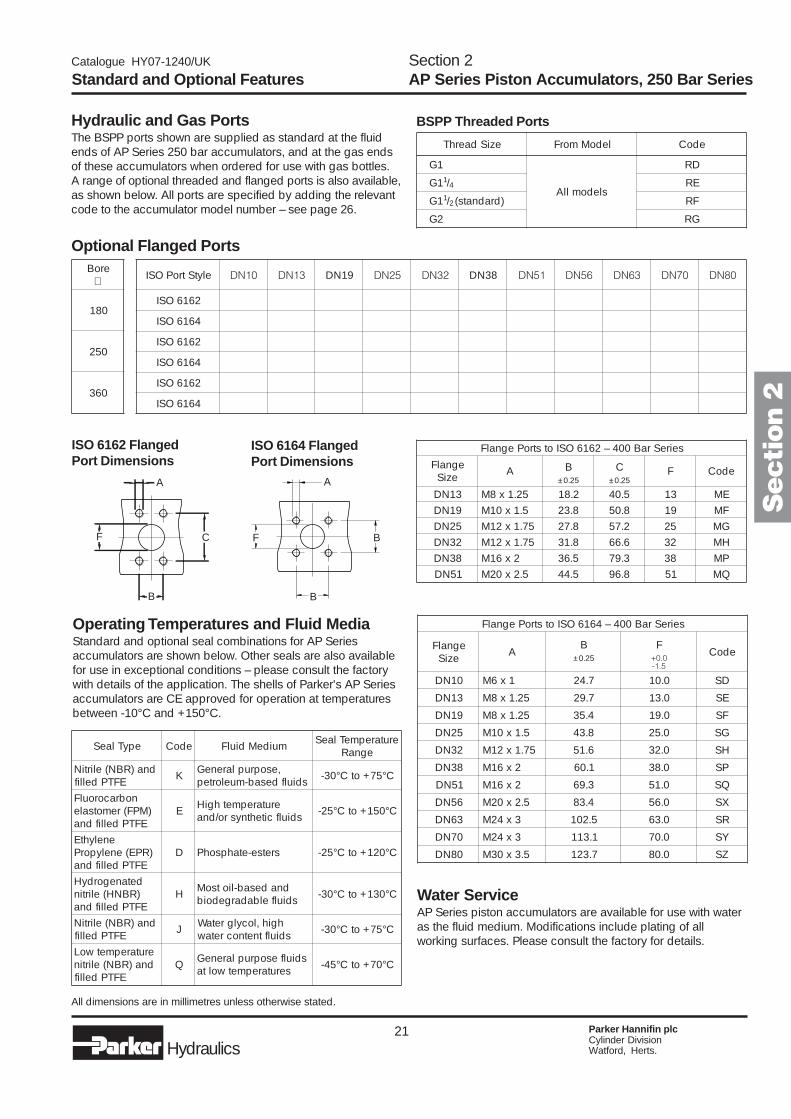
ISO 6164 FlangedPort Dimensions
Operating Temperatures and Fluid MediaStandard and optional seal combinations for AP Seriesaccumulators are shown below. Other seals are also availablefor use in exceptional conditions – please consult the factorywith details of the application. The shells of Parker's AP Seriesaccumulators are CE approved for operation at temperaturesbetween -10°C and +150°C.
Hydraulic and Gas PortsThe BSPP ports shown are supplied as standard at the fluidends of AP Series 250 bar accumulators, and at the gas endsof these accumulators when ordered for use with gas bottles.A range of optional threaded and flanged ports is also available,as shown below. All ports are specified by adding the relevantcode to the accumulator model number – see page 26.
Section 2AP Series Piston Accumulators, 250 Bar SeriesStandard and Optional Features
BSPP Threaded Ports
ISO 6162 FlangedPort Dimensions
All dimensions are in millimetres unless otherwise stated.
Water ServiceAP Series piston accumulators are available for use with wateras the fluid medium. Modifications include plating of allworking surfaces. Please consult the factory for details.
Secti
on 2
A
B
F C
A
B
F B
eziSdaerhT ledoMmorF edoC
1G
sledomllA
DR
1G 1/4 ER
1G 1/2 )dradnats( FR
2G GR
eroB∅
081
052
063
elytStroPOSI 01ND 31ND 91ND 52ND 23ND 83ND 15ND 65ND 36ND 07ND 08ND
2616OSI ü ü ü ü ü ü
4616OSI ü ü ü ü ü ü ü ü ü
2616OSI ü ü ü ü ü ü
4616OSI ü ü ü ü ü ü ü ü ü ü ü
2616OSI ü ü ü ü ü ü
4616OSI ü ü ü ü ü ü ü ü ü ü ü
epyTlaeS edoC muideMdiulF erutarepmeTlaeSegnaR
dna)RBN(elirtiNEFTPdellif K ,esopruplareneG
sdiulfdesab-muelortep C°57+otC°03-
nobracoroulF)MPF(remotsale
EFTPdellifdnaE erutarepmethgiH
sdiulfcitehtnysro/dna C°051+otC°52-
enelyhtE)RPE(enelyporP
EFTPdellifdnaD sretse-etahpsohP C°021+otC°52-
detanegordyH)RBNH(elirtinEFTPdellifdna
H dnadesab-liotsoMsdiulfelbadargedoib C°031+otC°03-
dna)RBN(elirtiNEFTPdellif J hgih,locylgretaW
sdiulftnetnocretaw C°57+otC°03-
erutarepmetwoLdna)RBN(elirtin
EFTPdellifQ sdiulfesopruplareneG
serutarepmetwolta C°07+otC°54-
seireSraB004–2616OSIotstroPegnalF
egnalFeziS A B C F edoC
52.0± 52.0±
31ND 52.1x8M 2.81 5.04 31 EM91ND 5.1x01M 8.32 8.05 91 FM52ND 57.1x21M 8.72 2.75 52 GM23ND 57.1x21M 8.13 6.66 23 HM83ND 2x61M 5.63 3.97 83 PM15ND 5.2x02M 5.44 8.69 15 QM
seireSraB004–4616OSIotstroPegnalF
egnalFeziS A
B FedoC
52.0± 0.0+5.1-
01ND 1x6M 7.42 0.01 DS
31ND 52.1x8M 7.92 0.31 ES
91ND 52.1x8M 4.53 0.91 FS
52ND 5.1x01M 8.34 0.52 GS
23ND 57.1x21M 6.15 0.23 HS
83ND 2x61M 1.06 0.83 PS
15ND 2x61M 3.96 0.15 QS
65ND 5.2x02M 4.38 0.65 XS
36ND 3x42M 5.201 0.36 RS
07ND 3x42M 1.311 0.07 YS
08ND 5.3x03M 7.321 0.08 ZS
22 Parker Hannifin plcCylinder DivisionWatford, Herts.Hydraulics
Catalogue HY07-1240/UK
350 Bar Models, Capacities and Dimensions
All dimensions are in millimetres unless otherwise stated.
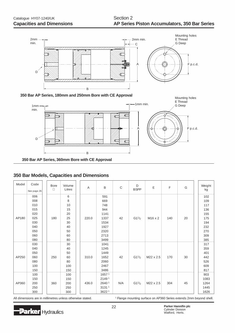
Capacities and DimensionsSection 2AP Series Piston Accumulators, 350 Bar Series
D
A
C
Mounting holesE ThreadG Deep
350 Bar AP Series, 180mm and 250mm Bore with CE Approval
350 Bar AP Series, 360mm Bore with CE Approval
B
2mmmin.
2mm min.
F p.c.d.
1mmmin.
D
B
1mm min.
A
Mounting holesE ThreadG Deep
F p.c.d.
1 Flange mounting surface on AP360 Series extends 2mm beyond shell.
ledoM edoC
62egapeeS
081PA
600800010510020520030040050060080
052PA
030040050060080001051
063PA
001051002052003
eroB∅
emuloVsertiL
081
68015102520304050608
052
0304050608001051
063
001051002052003
thgieWgk
2019017116315515714912320729035837139531042446259067183093801462154416261
A B C DPPSB E F G
0.022
195
24 1G 1/2 2x61M 041 02
9668474491411733143517291023231729943
0.013
1401
24 1G 1/2 5.2x22M 071 03
542194412561060276426843
0.634
7561 1
A/N 1G 1/2 5.2x22M 403 549412 1
0462 1
1313 1
2263 1
23 Parker Hannifin plcCylinder DivisionWatford, Herts.Hydraulics
Catalogue HY07-1240/UK Section 2AP Series Piston Accumulators, 350 Bar SeriesStandard and Optional Features
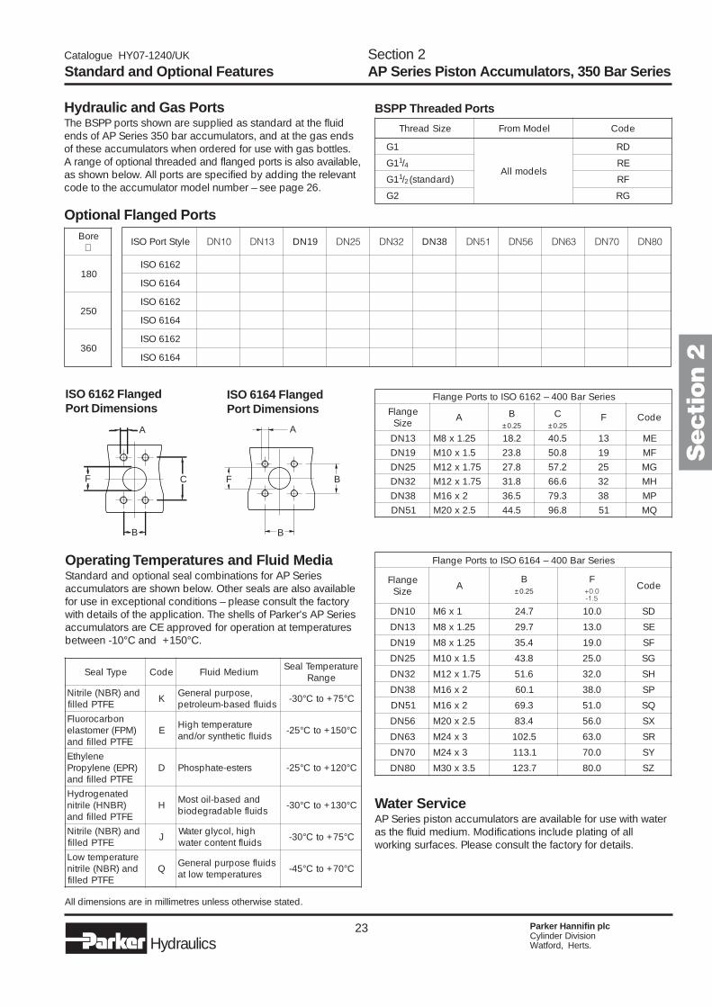
Optional Flanged Ports
ISO 6164 FlangedPort Dimensions
Operating Temperatures and Fluid MediaStandard and optional seal combinations for AP Seriesaccumulators are shown below. Other seals are also availablefor use in exceptional conditions – please consult the factorywith details of the application. The shells of Parker's AP Seriesaccumulators are CE approved for operation at temperaturesbetween -10°C and +150°C.
Hydraulic and Gas PortsThe BSPP ports shown are supplied as standard at the fluidends of AP Series 350 bar accumulators, and at the gas endsof these accumulators when ordered for use with gas bottles.A range of optional threaded and flanged ports is also available,as shown below. All ports are specified by adding the relevantcode to the accumulator model number – see page 26.
BSPP Threaded Ports
ISO 6162 FlangedPort Dimensions
All dimensions are in millimetres unless otherwise stated.
Water ServiceAP Series piston accumulators are available for use with wateras the fluid medium. Modifications include plating of allworking surfaces. Please consult the factory for details.
Secti
on 2
A
B
F C
A
B
BF
eziSdaerhT ledoMmorF edoC
1G
sledomllA
DR
1G 1/4 ER
1G 1/2 )dradnats( FR
2G GR
eroB∅
081
052
063
elytStroPOSI 01ND 31ND 91ND 52ND 23ND 83ND 15ND 65ND 36ND 07ND 08ND
2616OSI ü ü ü ü ü ü
4616OSI ü ü ü ü ü ü ü ü ü
2616OSI ü ü ü ü ü ü
4616OSI ü ü ü ü ü ü ü ü ü ü ü
2616OSI ü ü ü ü ü ü
4616OSI ü ü ü ü ü ü ü ü ü ü ü
epyTlaeS edoC muideMdiulF erutarepmeTlaeSegnaR
dna)RBN(elirtiNEFTPdellif K ,esopruplareneG
sdiulfdesab-muelortep C°57+otC°03-
nobracoroulF)MPF(remotsale
EFTPdellifdnaE erutarepmethgiH
sdiulfcitehtnysro/dna C°051+otC°52-
enelyhtE)RPE(enelyporP
EFTPdellifdnaD sretse-etahpsohP C°021+otC°52-
detanegordyH)RBNH(elirtinEFTPdellifdna
H dnadesab-liotsoMsdiulfelbadargedoib C°031+otC°03-
dna)RBN(elirtiNEFTPdellif J hgih,locylgretaW
sdiulftnetnocretaw C°57+otC°03-
erutarepmetwoLdna)RBN(elirtin
EFTPdellifQ sdiulfesopruplareneG
serutarepmetwolta C°07+otC°54-
seireSraB004–2616OSIotstroPegnalF
egnalFeziS A B C F edoC
52.0± 52.0±
31ND 52.1x8M 2.81 5.04 31 EM91ND 5.1x01M 8.32 8.05 91 FM52ND 57.1x21M 8.72 2.75 52 GM23ND 57.1x21M 8.13 6.66 23 HM83ND 2x61M 5.63 3.97 83 PM15ND 5.2x02M 5.44 8.69 15 QM
seireSraB004–4616OSIotstroPegnalF
egnalFeziS A
B FedoC
52.0± 0.0+5.1-
01ND 1x6M 7.42 0.01 DS
31ND 52.1x8M 7.92 0.31 ES
91ND 52.1x8M 4.53 0.91 FS
52ND 5.1x01M 8.34 0.52 GS
23ND 57.1x21M 6.15 0.23 HS
83ND 2x61M 1.06 0.83 PS
15ND 2x61M 3.96 0.15 QS
65ND 5.2x02M 4.38 0.65 XS
36ND 3x42M 5.201 0.36 RS
07ND 3x42M 1.311 0.07 YS
08ND 5.3x03M 7.321 0.08 ZS
24 Parker Hannifin plcCylinder DivisionWatford, Herts.Hydraulics
Catalogue HY07-1240/UK
Options, Spares and Accessories
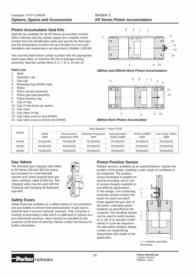
Piston Accumulator Seal KitsSeal kits are available for all AP Series accumulator models.When ordering seal kits, please supply the complete modelnumber from the identification plate and specify the fluid typeand the temperature at which the accumulator is to be used.Installation and maintenance are described in Bulletin 1240-M1.
The seal kits listed below contain a piston with the appropriateseals ready fitted, to minimize the risk of damage duringassembly. Seal kits contain items 5, 6, 7, 8, 9, 10 and 12.
Parts List1 Shell2 Hydraulic cap3 Gas cap4 Retaining ring (AP360 only)5 Piston6 Piston oil seal assembly7 Piston gas seal assembly8 Piston bearing ring9 Cap O-ring10 Cap O-ring back-up washer11 Gas valve12 Gas valve O-ring13 Gas valve protector (not AP360)14 Gas valve protector screw (not AP360)
Section 2AP Series Piston Accumulators
Gas ValvesThe standard gas charging valve fittedto AP Series 250 and 350 bar pistonaccumulators is a mechanicallyopened and closed poppet-type gasvalve cartridge, rated at 350 bar. Thischarging valve may be used with theCharging and Gauging Kit illustratedopposite.
Safety FusesSafety fuses are available as a safety feature on accumulatorsand gas bottles to prevent over-pressurization of gas due toexternal heat or excess hydraulic pressure. They comprise ahousing incorporating a disk which is calibrated to rupture at apre-determined pressure, which should be specified by thecustomer at the time of ordering. Please contact the factory forfurther information.
360mm Bore Piston Accumulator
180mm and 250mm Bore Piston Accumulators
Piston Position SensorPosition sensors, available as an optional feature, register theposition of the piston, enabling a wide range of conditions tobe monitored. The positionsensor illustrated is suitable forvertical mounting, and is oneof several designs available tosuit differing applications.In this design, non-contactingproximity sensors monitor thetravel of a steel rod whichbears against the gas side ofthe piston, indicating pistonpositions as specified by thecustomer. The resulting signalscan be used to switch pumpson or off, or to operate controlvalves in a pre-set sequence.For alternative designs, pleasecontact our EngineeringDepartment with details of theapplication.
x = customer specifieddimension
x
x
13
68
12
5
7
9 10
11
2
44
1
2 3
68
12
5
7
9 10
11
13
14
ledoM
081PA
052PA
063PA
EFTPdelliF+lairetaMlaeS
elirtiNRBN
nobracoroulFMPFremotsalE
enelyporPenelyhtERPE
detanegordyHRBNHelirtiN
)FBWH(elirtiNRBN
elirtiN.pmeTwoLRBN
KPA081KP EPA081KP DPA081KP HPA081KP JPA081KP QPA081KP
KPA052KP EPA052KP DPA052KP HPA052KP JPA052KP QPA052KP
KPA063KP EPA063KP DPA063KP HPA063KP JPA063KP QPA063KP
25 Parker Hannifin plcCylinder DivisionWatford, Herts.Hydraulics
Catalogue HY07-1240/UK
Charging and GaugingThe charging and gauging assemblies listed in the tableare suitable for use with the standard poppet-type gas valve.Each kit contains a UCA assembly incorporating a gas valve,bleed valve and gas chuck, and a 3m long charging hose withstandard nitrogen bottle fittings. The kit includes 25 bar and250 bar pressure gauges, to permit easy monitoring of thegas precharge.
Options, Spares and AccessoriesSection 2AP Series Piston Accumulators
'U' Bolts for Piston Accumulators
Note: 'U' bolts should never be mounted morethan 75mm from the end of the accumulator toavoid deformation of the shell.
All dimensions are in millimetres unless otherwise stated.
Welded lug
75mm max
Mounting surface
75mm max
Piston accumulator'U' bolt
A B
C
D
E
Inflation valve
Bleed valve
Adapters
Pressure gauge
Hose
Secti
on 2
ledoMerusserP
gnitaR
081PA052053
052PA052053
063PA052053
.oNtraP
5-3901EP8-3901EP
6-3901EP9-3901EP
01-3901EP11-3901EP
A B C D E
2x61M012422
622042
081581
59
5.2x02M682213
603233
042652
511
3x72M804834
534564
092003
531051
yrotirreT gnittiFelttoBsaG .oNtraP
KU )elam(PSB8/5 20ACU
ecnarF )elamef("41/1x7.12W 40ACU
ynamreG )elamef("41/1x23.42W 10ACU
ylatI )elam("41/1x7.12W 50ACU
SU )elam("41/1x069.0 30ACU
26 Parker Hannifin plcCylinder DivisionWatford, Herts.Hydraulics
Catalogue HY07-1240/UK
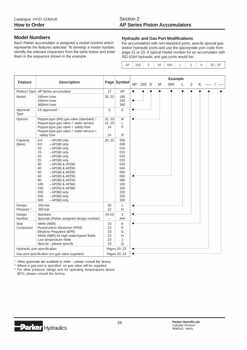
Hydraulic and Gas Port ModificationsFor accumulators with non-standard ports, specify special gasand/or hydraulic ports and use the appropriate port code frompage 21 or 23. A typical model number for an accumulator withISO 6164 hydraulic and gas ports would be:
Model NumbersEach Parker accumulator is assigned a model number whichrepresents the features selected. To develop a model number,identify the relevant characters from the table below and enterthem in the sequence shown in the example.
Product Type AP Series accumulator 17 AP
Model 180mm bore 20, 22 180250mm bore 250360mm bore 360
Approval CE approved 1 5 EType
Options Poppet-type (MS) gas valve (standard) 2 21, 23 MPoppet-type gas valve + water service 21, 23 LPoppet-type gas valve + safety fuse 24 PPoppet-type gas valve + water service + safety fuse 24 R
Capacity 6.0 – AP180 only 20, 22 006(litres) 8.0 – AP180 only 008
10 – AP180 only 01015 – AP180 only 01520 – AP180 only 02025 – AP180 only 02530 – AP180 & AP250 03040 – AP180 & AP250 04050 – AP180 & AP250 05060 – AP180 & AP250 06080 – AP180 & AP250 080100 – AP250 & AP360 100150 – AP250 & AP360 150200 – AP360 only 200250 – AP360 only 250300 – AP360 only 300
Design 250 bar 20 LPressure 3 350 bar 22 H
Design Standard 20-23 2Number Specials (Parker assigned design number) – ###
Seal Nitrile (NBR) 23 KCompound Fluorocarbon Elastomer (FPM) 23 E
Ethylene Propylene (EPR) 23 DNitrile (NBR) for high water-based fluids 23 HLow temperature nitrile 23 JSpecial – please specify 23 Q
Hydraulic port specification Pages 20- 23
Gas port specification (no gas valve supplied) Pages 20- 23
Feature Description Page SymbolExample
AP 250 E M 060 L 2 K – – / – –
How to OrderSection 2AP Series Piston Accumulators
1 Other approvals are available to order – please consult the factory.2 Where a gas port is specified, no gas valve will be supplied.3 For other pressure ratings and for operating temperatures above
80°C, please consult the factory.
PA 052 E M 080 L 2 K FS/FS
27 Parker Hannifin plcCylinder DivisionWatford, Herts.Hydraulics
Catalogue HY07-1240/UK
Contents250 bar gas bottles ............................................... 30350 bar gas bottles ............................................... 31
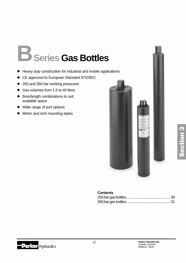
� Heavy duty construction for industrial and mobile applications
� CE approved to European Standard 97/23/EC
� 250 and 350 bar working pressures
� Gas volumes from 1.5 to 40 litres
� Bore/length combinations to suitavailable space
� Wide range of port options
� Metric and inch mounting styles
B Series Gas Bottles
Secti
on 3
28 Parker Hannifin plcCylinder DivisionWatford, Herts.Hydraulics
Catalogue HY07-1240/UK
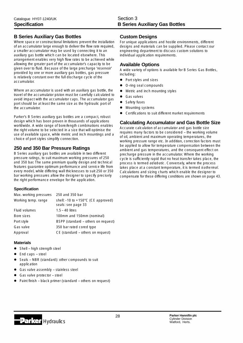
B Series Auxiliary Gas BottlesWhere space or constructional limitations prevent the installationof an accumulator large enough to deliver the flow rate required,a smaller accumulator may be used by connecting it to anauxiliary gas bottle which can be located elsewhere. Thisarrangement enables very high flow rates to be achieved whileallowing the greater part of the accumulator's capacity to begiven over to fluid. Because of the large precharge ‘reservoir’provided by one or more auxiliary gas bottles, gas pressureis relatively constant over the full discharge cycle of theaccumulator.
Where an accumulator is used with an auxiliary gas bottle, thetravel of the accumulator piston must be carefully calculated toavoid impact with the accumulator caps. The accumulator gasport should be at least the same size as the hydraulic port ofthe accumulator.
Parker's B Series auxiliary gas bottles are a compact, robustdesign which has been proven in thousands of applicationsworldwide. A wide range of bore/length combinations enablesthe right volume to be selected in a size that will optimise theuse of available space, while metric and inch mountings and achoice of port styles simplify connection.
250 and 350 Bar Pressure RatingsB Series auxiliary gas bottles are available in two differentpressure ratings, to suit maximum working pressures of 250and 350 bar. The same premium quality design and technicalfeatures guarantee optimum performance and service life fromevery model, while differing wall thicknesses to suit 250 or 350bar working pressures allow the designer to specify preciselythe right performance envelope for the application.
SpecificationMax. working pressures 250 and 350 barWorking temp. range shell: -10 to +150°C (CE approved)
seals: see page 33Fluid volumes 1.5– 40 litresBore sizes 100mm and 150mm (nominal)Port style BSPP (standard – others on request)Gas valve 350 bar rated cored typeApproval CE (standard – others on request)
Materials� Shell – high strength steel� End caps – steel� Seals – NBR (standard): other compounds to suit
application� Gas valve assembly – stainless steel� Gas valve protector – steel� Paint finish – black primer (standard – others on request)
Custom DesignsFor unique applications and hostile environments, differentdesigns and materials can be supplied. Please contact ourengineering department to discuss custom solutions toindividual application requirements.
Available OptionsA wide variety of options is available for B Series Gas Bottles,including:� Port styles and sizes� O-ring seal compounds� Metric and inch mounting styles� Gas valves� Safety fuses� Mounting systems� Certifications to suit different market requirements
Calculating Accumulator and Gas Bottle SizeAccurate calculation of accumulator and gas bottle sizerequires many factors to be considered – the working volumeof oil, ambient and maximum operating temperatures, theworking pressure range etc. In addition, correction factors mustbe applied to allow for temperature compensation between theambient and gas temperatures, and the consequent effect onprecharge pressure in the accumulator. Where the workingcycle is sufficiently rapid that no heat transfer takes place, theprocess is termed adiabatic. Conversely, where the processtakes place at a constant temperature, it is termed isothermal.Calculations and sizing charts which enable the designer tocompensate for these differing conditions are shown on page 43.
SpecificationSection 3B Series Auxiliary Gas Bottles
29 Parker Hannifin plcCylinder DivisionWatford, Herts.Hydraulics
Catalogue HY07-1240/UK
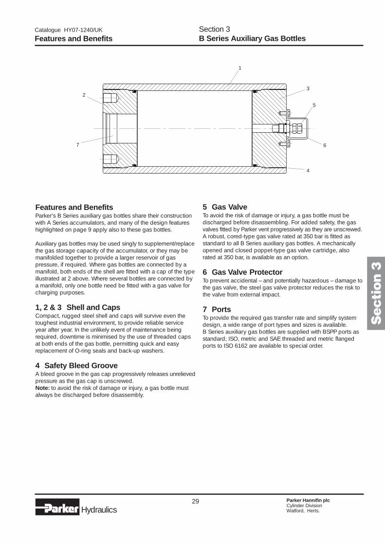
Features and BenefitsParker's B Series auxiliary gas bottles share their constructionwith A Series accumulators, and many of the design featureshighlighted on page 9 apply also to these gas bottles.
Auxiliary gas bottles may be used singly to supplement/replacethe gas storage capacity of the accumulator, or they may bemanifolded together to provide a larger reservoir of gaspressure, if required. Where gas bottles are connected by amanifold, both ends of the shell are fitted with a cap of the typeillustrated at 2 above. Where several bottles are connected bya manifold, only one bottle need be fitted with a gas valve forcharging purposes.
1, 2 & 3 Shell and CapsCompact, rugged steel shell and caps will survive even thetoughest industrial environment, to provide reliable serviceyear after year. In the unlikely event of maintenance beingrequired, downtime is minimised by the use of threaded capsat both ends of the gas bottle, permitting quick and easyreplacement of O-ring seals and back-up washers.
4 Safety Bleed GrooveA bleed groove in the gas cap progressively releases unrelievedpressure as the gas cap is unscrewed.Note: to avoid the risk of damage or injury, a gas bottle mustalways be discharged before disassembly.
Features and BenefitsSection 3B Series Auxiliary Gas Bottles
5 Gas ValveTo avoid the risk of damage or injury, a gas bottle must bedischarged before disassembling. For added safety, the gasvalves fitted by Parker vent progressively as they are unscrewed.A robust, cored-type gas valve rated at 350 bar is fitted asstandard to all B Series auxiliary gas bottles. A mechanicallyopened and closed poppet-type gas valve cartridge, alsorated at 350 bar, is available as an option.
6 Gas Valve ProtectorTo prevent accidental – and potentially hazardous – damage tothe gas valve, the steel gas valve protector reduces the risk tothe valve from external impact.
7 PortsTo provide the required gas transfer rate and simplify systemdesign, a wide range of port types and sizes is available.B Series auxiliary gas bottles are supplied with BSPP ports asstandard; ISO, metric and SAE threaded and metric flangedports to ISO 6162 are available to special order.
Secti
on 3
1
2
3
4
5
67

30 Parker Hannifin plcCylinder DivisionWatford, Herts.Hydraulics
Catalogue HY07-1240/UK
250 Bar B Series Gas Bottlewith CE Approval
All dimensions are in millimetres unless otherwise stated.
250 Bar Models, Capacities and Dimensions
Capacities and DimensionsSection 3B Series Auxiliary Gas Bottles, 250 Bar Series
Gas ValvesThe standard gas charging valve fitted to B Series 250 and350 bar auxiliary gas bottles is a cored-type gas valve, rated at350 bar. A mechanically opened and closed poppet-type gasvalve cartridge, also rated at 350 bar, is available as an option.
Both types of charging valve may be used with the Chargingand Gauging Kit illustrated on page 32.
Standard Cored-TypeGas Valve
Optional Poppet-TypeGas Valve
1 B Series 250 bar gas bottles are supplied as standard with the metric threaded mounting holes shown in the table. They are also available withinch pattern mounting holes, indicated by the Design Number in the model code – see page 34.
D
B
A
CMounting holesE ThreadG Deep F p.c.d.
ledoM edoC
43egaPeeS
4B
8500
6110
1320
7430
8750
6B
1320
7430
8750
4290
5511
3371
0132
eroB emuloVsertiL∅
4.201
5.1
5.2
0.4
0.6
01
9.641
0.5
0.7
11
71
02
03
04
thgieWgk
31
61
12
72
93
03
63
84
76
97
701
641
A B CtroPsaG–D
E 1 F GPPSB
121
592
92 1G 21M 28 81
114
046
178
0331
571
244
92 1G 1/2 21M 011 81
455
877
3111
7331
6981
4542
31 Parker Hannifin plcCylinder DivisionWatford, Herts.Hydraulics
Catalogue HY07-1240/UK
350 Bar B Series Gas Bottlewith CE Approval
All dimensions are in millimetres unless otherwise stated.
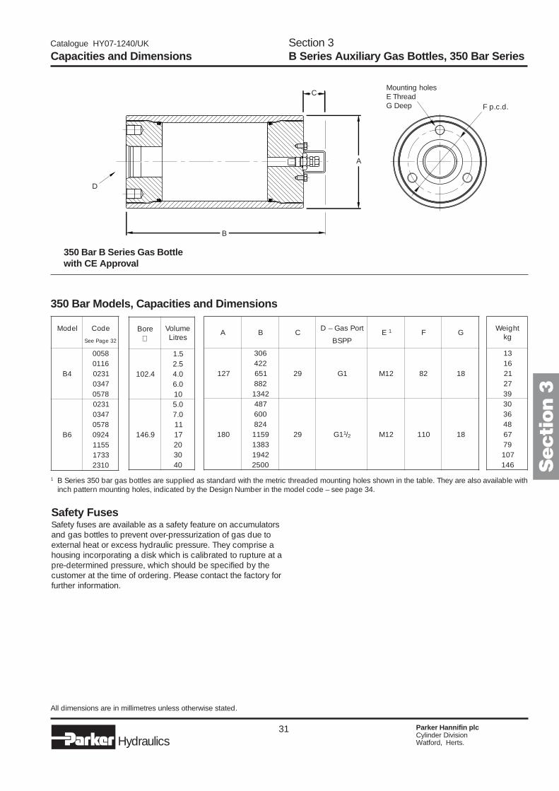
350 Bar Models, Capacities and Dimensions
Capacities and DimensionsSection 3B Series Auxiliary Gas Bottles, 350 Bar Series
Safety FusesSafety fuses are available as a safety feature on accumulatorsand gas bottles to prevent over-pressurization of gas due toexternal heat or excess hydraulic pressure. They comprise ahousing incorporating a disk which is calibrated to rupture at apre-determined pressure, which should be specified by thecustomer at the time of ordering. Please contact the factory forfurther information.
1 B Series 350 bar gas bottles are supplied as standard with the metric threaded mounting holes shown in the table. They are also available withinch pattern mounting holes, indicated by the Design Number in the model code – see page 34.
D
B
A
CMounting holesE ThreadG Deep F p.c.d.
Secti
on 3
A B C troPsaG–D E 1 F GPPSB
721
603
92 1G 21M 28 812241562882431
081
784
92 1G 1/2 21M 011 81
0064289511383124910052
thgieWgk
31611272930363847697701641
ledoM edoC
23egaPeeS
4B
85006110132074308750
6B
1320743087504290551133710132
eroB emuloVsertiL∅
4.201
5.15.20.40.601
9.641
0.50.71171020304
32 Parker Hannifin plcCylinder DivisionWatford, Herts.Hydraulics
Catalogue HY07-1240/UK
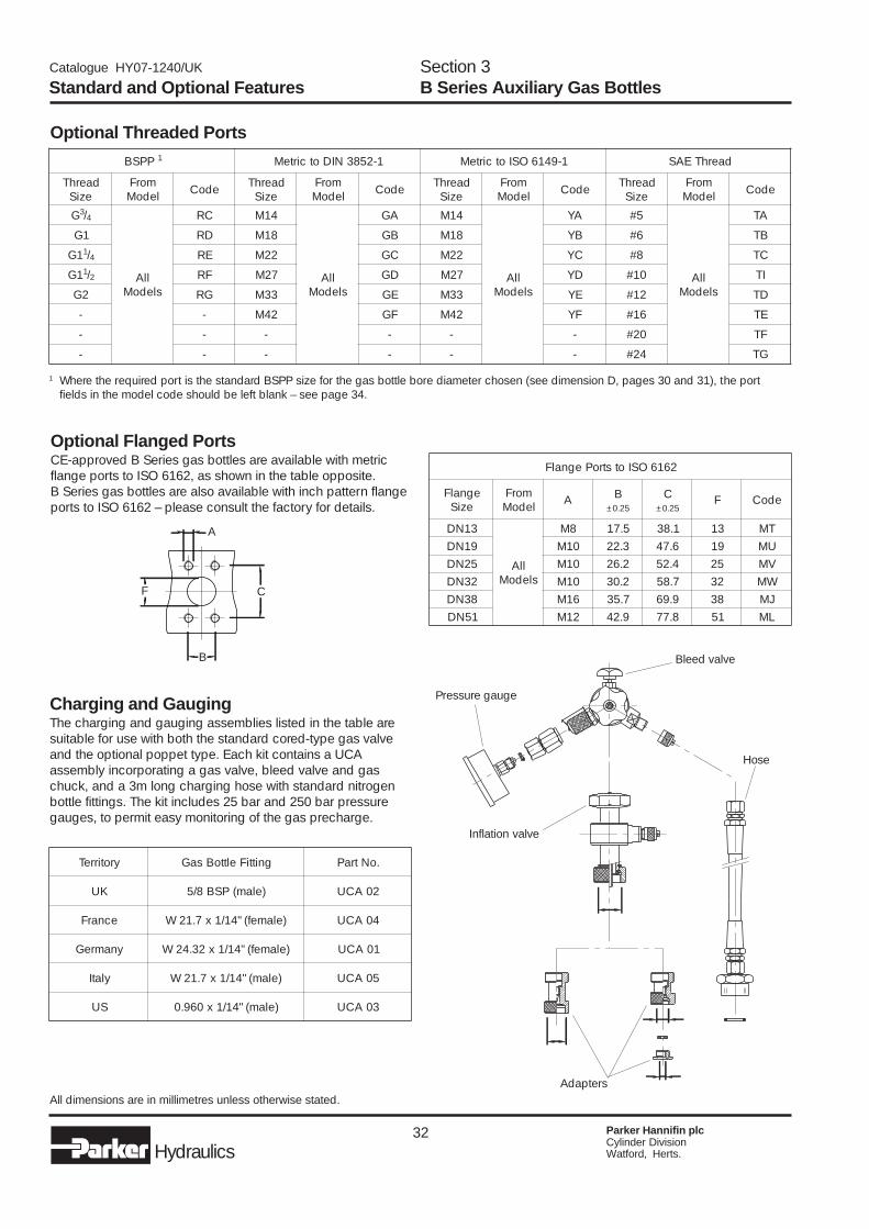
Optional Threaded Ports
Optional Flanged PortsCE-approved B Series gas bottles are available with metricflange ports to ISO 6162, as shown in the table opposite.B Series gas bottles are also available with inch pattern flangeports to ISO 6162 – please consult the factory for details.
1 Where the required port is the standard BSPP size for the gas bottle bore diameter chosen (see dimension D, pages 30 and 31), the portfields in the model code should be left blank – see page 34.
Standard and Optional FeaturesSection 3B Series Auxiliary Gas Bottles
All dimensions are in millimetres unless otherwise stated.
Charging and GaugingThe charging and gauging assemblies listed in the table aresuitable for use with both the standard cored-type gas valveand the optional poppet type. Each kit contains a UCAassembly incorporating a gas valve, bleed valve and gaschuck, and a 3m long charging hose with standard nitrogenbottle fittings. The kit includes 25 bar and 250 bar pressuregauges, to permit easy monitoring of the gas precharge.
Inflation valve
Bleed valve
Adapters
Pressure gauge
Hose
A
B
F C
PPSB 1 1-2583NIDotcirteM 1-9416OSIotcirteM daerhTEAS
daerhTeziS
morFledoM edoC daerhT
eziSmorF
ledoM edoC daerhTeziS
morFledoM edoC daerhT
eziSmorF
ledoM edoC
G3/4
llAsledoM
CR 41M
llAsledoM
AG 41M
llAsledoM
AY 5#
llAsledoM
AT
1G DR 81M BG 81M BY 6# BT
1G 1/4 ER 22M CG 22M CY 8# CT
1G 1/2 FR 72M DG 72M DY 01# IT
2G GR 33M EG 33M EY 21# DT
- - 24M FG 24M FY 61# ET
- - - - - - 02# FT
- - - - - - 42# GT
yrotirreT gnittiFelttoBsaG .oNtraP
KU )elam(PSB8/5 20ACU
ecnarF )elamef("41/1x7.12W 40ACU
ynamreG )elamef("41/1x23.42W 10ACU
ylatI )elam("41/1x7.12W 50ACU
SU )elam("41/1x069.0 30ACU
2616OSIotstroPegnalF
egnalFeziS
morFledoM A B C F edoC
52.0± 52.0±
31ND
llAsledoM
8M 5.71 1.83 31 TM91ND 01M 3.22 6.74 91 UM52ND 01M 2.62 4.25 52 VM23ND 01M 2.03 7.85 23 WM83ND 61M 7.53 9.96 83 JM15ND 21M 9.24 8.77 15 LM
33 Parker Hannifin plcCylinder DivisionWatford, Herts.Hydraulics
Catalogue HY07-1240/UK
Options, Spares and AccessoriesSection 3B Series Auxiliary Gas Bottles
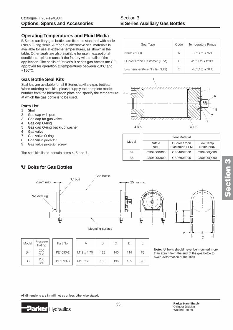
'U' Bolts for Gas Bottles
Note: 'U' bolts should never be mounted morethan 25mm from the end of the gas bottle toavoid deformation of the shell.
All dimensions are in millimetres unless otherwise stated.
Operating Temperatures and Fluid MediaB Series auxiliary gas bottles are fitted as standard with nitrile(NBR) O-ring seals. A range of alternative seal materials isavailable for use at extreme temperatures, as shown in thetable. Other seals are also available for use in exceptionalconditions – please consult the factory with details of theapplication. The shells of Parker's B series gas bottles are CEapproved for operation at temperatures between -10°C and+150°C.
Gas Bottle Seal KitsSeal kits are available for all B Series auxiliary gas bottles.When ordering seal kits, please supply the complete modelnumber from the identification plate and specify the temperatureat which the gas bottle is to be used.
Parts List1 Shell2 Gas cap with port3 Gas cap for gas valve4 Gas cap O-ring5 Gas cap O-ring back-up washer6 Gas valve7 Gas valve O-ring8 Gas valve protector
9 Gas valve protector screw
The seal kits listed contain items 4, 5 and 7.
Welded lug
25mm max
Mounting surface
25mm max
Gas Bottle'U' bolt
A B
C
D
E
Secti
on 3
1
23
4 & 5
6
8
9
7
4 & 5
epyTlaeS edoC egnaRerutarepmeT
)RBN(elirtiN K C°57+otC°03-
)MPF(remotsalEnobracoroulF E C°021+otC°52-
)RBN(elirtiNerutarepmeTwoL Q C°07+otC°54-
ledoM
4B
6B
lairetaMlaeS
elirtiNRBN
nobracoroulFMPFremotsalE
.pmeTwoLRBNelirtiN
000K0040BC 000E0040BC 000Q0040BC
000K0060BC 000E0060BC 000Q0060BC
ledoMerusserP
gnitaR
4B052053
6B052053
.oNtraP
2-3901EP
3-3901EP
A B C D E
57.1x21M 821 041 411 67
2x61M 081 691 551 59
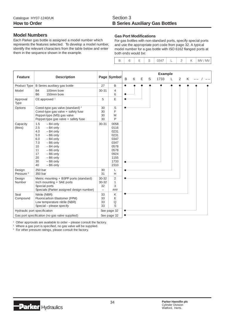
34 Parker Hannifin plcCylinder DivisionWatford, Herts.Hydraulics
Catalogue HY07-1240/UK
Gas Port ModificationsFor gas bottles with non-standard ports, specify special portsand use the appropriate port code from page 32. A typicalmodel number for a gas bottle with ISO 6162 flanged ports atboth ends would be:
Model NumbersEach Parker gas bottle is assigned a model number whichrepresents the features selected. To develop a model number,identify the relevant characters from the table below and enterthem in the sequence shown in the example.
Product Type B Series auxiliary gas bottle 27 B
Model B4 100mm bore 30-31 4B6 150mm bore 6
Approval CE approved 1 5 EType
Options Cored-type gas valve (standard) 2 30 SCored-type gas valve + safety fuse 30 FPoppet-type (MS) gas valve 30 MPoppet-type gas valve + safety fuse 30 P
Capacity 1.5 – B4 only 30-31 0058(litres) 2.5 – B4 only 0116
4.0 – B4 only 02315.0 – B6 only 02316.0 – B4 only 03477.0 – B6 only 034710 – B4 only 057811 – B6 only 057817 – B6 only 092420 – B6 only 115530 – B6 only 173340 – B6 only 2310
Design 250 bar 30 LPressure 3 350 bar 31 H
Design Metric mounting + BSPP ports (standard) 30-32 2Number Inch mounting + SAE ports 30-32 1
Special ports 32 3Specials (Parker assigned design number) – ###
Seal Nitrile (NBR) 33 KCompound Fluorocarbon Elastomer (FPM) 33 E
Low temperature nitrile (NBR) 33 QSpecial – please specify 33 S
Hydraulic port specification See page 32
Gas port specification (no gas valve supplied) See page 32
Feature Description Page SymbolExample
B 6 E S 1733 L 2 K – – / – –
How to OrderSection 3B Series Auxiliary Gas Bottles
1 Other approvals are available to order – please consult the factory.2 Where a gas port is specified, no gas valve will be supplied.3 For other pressure ratings, please consult the factory.
B 6 E S 7430 L 2 K VM/VM

35 Parker Hannifin plcCylinder DivisionWatford, Herts.Hydraulics
Catalogue HY07-1240/UK
Contents250 bar gas bottles ......................................... 38350 bar gas bottles ......................................... 39
� Premium quality construction for demanding industrial applications
� CE approved to European Standard 97/23/EC
� 250 and 350 bar working pressures
� Gas volumes from 8.5 to 322 litres
� Bore/length combinations to suitavailable space
� High flow ports for rapidcycling performance
� Wide range of port options
BP Series Gas Bottles
Secti
on 4
36 Parker Hannifin plcCylinder DivisionWatford, Herts.Hydraulics
Catalogue HY07-1240/UK
BP Series Auxiliary Gas BottlesWhere space or constructional limitations prevent the installationof an accumulator large enough to deliver the flow rate required,a smaller accumulator may be used by connecting it to anauxiliary gas bottle which can be located elsewhere. Thisarrangement enables very high flow rates to be achieved whileallowing the greater part of the accumulator's capacity to begiven over to fluid. Because of the large precharge ‘reservoir’provided by one or more auxiliary gas bottles, gas pressureis relatively constant over the full discharge cycle of theaccumulator.
Where an accumulator is used with an auxiliary gas bottle, thetravel of the accumulator piston must be carefully calculated toavoid impact with the accumulator caps. The accumulator gasport should be at least the same size as the hydraulic port ofthe accumulator.
Parker's BP Series auxiliary gas bottles are a compact, robustdesign which can be used singly or in combination to providethe large capacities and high flow rates required in demandingapplications such as die casting and plastic injection moulding.A wide range of bore/length combinations enables the rightvolume to be selected in a size that will optimise the use ofavailable space, while a choice of port styles simplifiesconnection.
250 and 350 Bar Pressure RatingsBP Series auxiliary gas bottles are available in two differentpressure ratings, to suit maximum working pressures of 250and 350 bar. The same premium quality design and technicalfeatures guarantee optimum performance and service life fromevery model in each of the ranges, while differing wallthicknesses allow the designer to specify precisely the rightperformance envelope for the application.
SpecificationMax. working pressures 250 and 350 barWorking temp. range -10 to +80°C (to +150°C on request)Fluid volumes 8.5– 322 litresBore sizes 180, 250 and 360mmPort style BSPP (standard – others on request)Gas valve 350 bar rated poppet typeApproval CE (standard – others on request)
Materials� Shell – high strength steel� End caps – steel� Seals – NBR (standard): other compounds to suit
application� Gas valve assembly – stainless steel� Gas valve protector – steel� Paint finish – black primer, suitable for epoxy paint
finishes (standard) – other finishes on request
Custom DesignsFor unique applications and hostile environments, differentdesigns, materials and finishes can be supplied. Pleasecontact our engineering department to discuss customsolutions to individual application requirements.
Available OptionsA wide variety of options is available for BP Series gas bottles,including:� Port styles and sizes� O-ring seal compounds� Safety fuses� Mounting systems� Certifications to suit different market requirements
Calculating Accumulator and Gas Bottle SizeAccurate calculation of accumulator and gas bottle sizerequires many factors to be considered – the working volumeof oil, ambient and maximum operating temperatures, theworking pressure range etc. In addition, correction factors mustbe applied to allow for temperature compensation between theambient and gas temperatures, and the consequent effect onprecharge pressure in the accumulator. Where the workingcycle is sufficiently rapid that no heat transfer takes place, theprocess is termed adiabatic. Conversely, where the processtakes place at a constant temperature, it is termed isothermal.Calculations and sizing charts which enable the designer tocompensate for these differing conditions are shown on page 43.
SpecificationSection 4BP Series Auxiliary Gas Bottles

37 Parker Hannifin plcCylinder DivisionWatford, Herts.Hydraulics
Catalogue HY07-1240/UK
Features and BenefitsParker's BP Series auxiliary gas bottles share their constructionwith AP Series accumulators, and many of the design featureshighlighted on page 19 apply also to these gas bottles.
Auxiliary gas bottles may be used singly to supplement/replacethe gas storage capacity of the accumulator, or they may bemanifolded together to provide a larger reservoir of gaspressure, if required. Where gas bottles are connected by amanifold, only one bottle need be fitted with a gas valve forcharging purposes.
1, 2 & 3 Shell and CapsCompact, rugged steel shell and end caps will survive eventhe toughest industrial environment, to provide reliable serviceyear after year. 180mm and 250mm bore gas bottles featurethreaded caps to minimize downtime and simplify maintenance,permitting quick and easy replacement of O-ring seals in theunlikely event of replacement being required. 360mm boreunits (illustrated) use a screwed ring (3) to retain the gas caps,reducing the mass of parts handled during maintenance andproviding additional protection for the gas valve.
4 Safety Bleed GroovesA bleed groove in the gas cap progressively releases unrelievedgas pressure in the accumulator as the gas cap is unscrewed.Note: to avoid the risk of damage or injury, an accumulatormust always be discharged before disassembly.
5 Gas ValveTo avoid the risk of injury or damage, a gas bottle must bedischarged before disassembling. For added safety, the gasvalves fitted by Parker vent progressively as they are unscrewed.A robust, mechanically opened/closed poppet-type gas valverated at 350 bar is fitted as standard to all BP Series auxiliarygas bottles.
6 Gas Valve ProtectorTo prevent accidental – and potentially hazardous – damage tothe gas valve, 180mm and 250mm bore BP Series gas bottlesare fitted with a steel gas valve protector to reduce the risk tothe valve from external impact. The gas valve on 360mm boremodels is recessed within the shell to reduce the risk ofdamage.
7 PortsTo provide the required gas transfer rate and simplify systemdesign, a wide range of port types and sizes is available.BSPP ports are fitted as standard; metric flanged ports to ISO6162 and ISO 6164 are available as an option.
SpecificationSection 4BP Series Auxiliary Gas Bottles
1
2 2
4
5
7
360mm Bore BP Series Gas Bottle with Flange PortSee Page 38 for cutaway view of 180/250mm bore models
Secti
on 4
33
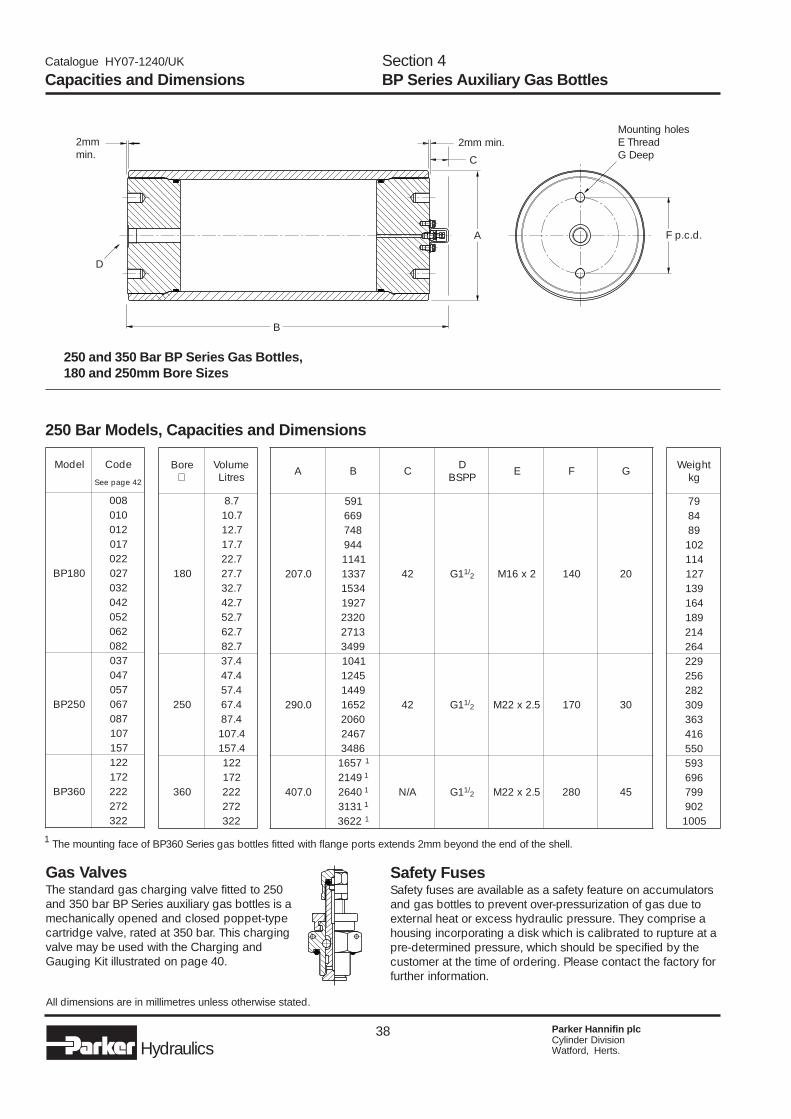
38 Parker Hannifin plcCylinder DivisionWatford, Herts.Hydraulics
Catalogue HY07-1240/UK
Safety FusesSafety fuses are available as a safety feature on accumulatorsand gas bottles to prevent over-pressurization of gas due toexternal heat or excess hydraulic pressure. They comprise ahousing incorporating a disk which is calibrated to rupture at apre-determined pressure, which should be specified by thecustomer at the time of ordering. Please contact the factory forfurther information.
250 and 350 Bar BP Series Gas Bottles,180 and 250mm Bore Sizes
All dimensions are in millimetres unless otherwise stated.
250 Bar Models, Capacities and Dimensions
Capacities and DimensionsSection 4BP Series Auxiliary Gas Bottles
Gas ValvesThe standard gas charging valve fitted to 250and 350 bar BP Series auxiliary gas bottles is amechanically opened and closed poppet-typecartridge valve, rated at 350 bar. This chargingvalve may be used with the Charging andGauging Kit illustrated on page 40.
1 The mounting face of BP360 Series gas bottles fitted with flange ports extends 2mm beyond the end of the shell.
D
A
C
Mounting holesE ThreadG Deep
B
2mmmin.
2mm min.
F p.c.d.
ledoM edoC
24egapeeS
081PB
800010210710220720230240250260280
052PB
730740750760780701751
063PB
221271222272223
eroB∅
emuloVsertiL
081
7.87.017.217.717.227.727.237.247.257.267.28
052
4.734.744.754.764.784.7014.751
063
221271222272223
thgieWgk
9748982014117219314619814124629226522829033636140553956969972095001
A B C DPPSB E F G
0.702
195
24 1G /1 2 2x61M 041 02
9668474491411733143517291023231729943
0.092
1401
24 1G /1 2 5.2x22M 071 03
542194412561060276426843
0.704
7561 1
A/N 1G /1 2 5.2x22M 082 549412 1
0462 1
1313 1
2263 1
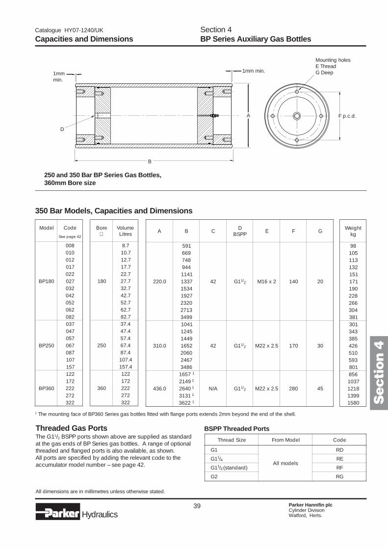
39 Parker Hannifin plcCylinder DivisionWatford, Herts.Hydraulics
Catalogue HY07-1240/UK
250 and 350 Bar BP Series Gas Bottles,360mm Bore size
All dimensions are in millimetres unless otherwise stated.
350 Bar Models, Capacities and Dimensions
Capacities and DimensionsSection 4BP Series Auxiliary Gas Bottles
1 The mounting face of BP360 Series gas bottles fitted with flange ports extends 2mm beyond the end of the shell.
Threaded Gas PortsThe G11/2 BSPP ports shown above are supplied as standardat the gas ends of BP Series gas bottles. A range of optionalthreaded and flanged ports is also available, as shown.All ports are specified by adding the relevant code to theaccumulator model number – see page 42.
BSPP Threaded Ports
D
A
Mounting holesE ThreadG Deep
B
1mmmin.
1mm min.
F p.c.d.
Secti
on 4
ledoM edoC
24egapeeS
081PB
800010210710220720230240250260280
052PB
730740750760780701751
063PB
221271222272223
eroB∅
emuloVsertiL
081
7.87.017.217.717.227.727.237.247.257.267.28
052
4.734.744.754.764.784.7014.751
063
221271222272223
thgieWgk
895013112311511710918226624031831033435836240153951086587301812199310851
eziSdaerhT ledoMmorF edoC
1G
sledomllA
DR
1G 1/4 ER
1G 1/2 )dradnats( FR
2G GR
A B C DPPSB E F G
0.022
195
24 1G /1 2 2x61M 041 02
9668474491411733143517291023231729943
0.013
1401
24 1G /1 2 5.2x22M 071 03
542194412561060276426843
0.634
7561 1
A/N 1G /1 2 5.2x22M 082 549412 1
0462 1
1313 1
2263 1
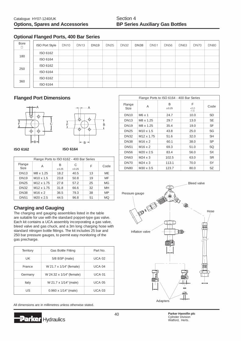
40 Parker Hannifin plcCylinder DivisionWatford, Herts.Hydraulics
Catalogue HY07-1240/UK
Options, Spares and AccessoriesSection 4BP Series Auxiliary Gas Bottles
Optional Flanged Ports, 400 Bar Series
Flanged Port Dimensions
All dimensions are in millimetres unless otherwise stated.
Charging and GaugingThe charging and gauging assemblies listed in the tableare suitable for use with the standard poppet-type gas valve.Each kit contains a UCA assembly incorporating a gas valve,bleed valve and gas chuck, and a 3m long charging hose withstandard nitrogen bottle fittings. The kit includes 25 bar and250 bar pressure gauges, to permit easy monitoring of thegas precharge.
ISO 6162 ISO 6164
Inflation valve
Bleed valve
Adapters
Pressure gauge
Hose
A
B
F C
A
B
BF
eroB∅
081
052
063
elytStroPOSI 01ND 31ND 91ND 52ND 23ND 83ND 15ND 65ND 36ND 07ND 08ND
2616OSI ü ü ü ü ü ü
4616OSI ü ü ü ü ü ü ü ü ü
2616OSI ü ü ü ü ü ü
4616OSI ü ü ü ü ü ü ü ü ü ü ü
2616OSI ü ü ü ü ü ü
4616OSI ü ü ü ü ü ü ü ü ü ü ü
yrotirreT gnittiFelttoBsaG .oNtraP
KU )elam(PSB8/5 20ACU
ecnarF )elamef("41/1x7.12W 40ACU
ynamreG )elamef("41/1x23.42W 10ACU
ylatI )elam("41/1x7.12W 50ACU
SU )elam("41/1x069.0 30ACU
seireSraB004-2616OSIotstroPegnalF
egnalFeziS A B C F edoC
52.0± 52.0±
31ND 52.1x8M 2.81 5.04 31 EM91ND 5.1x01M 8.32 8.05 91 FM52ND 57.1x21M 8.72 2.75 52 GM23ND 57.1x21M 8.13 6.66 23 HM83ND 2x61M 5.63 3.97 83 PM15ND 5.2x02M 5.44 8.69 15 QM
seireSraB004-4616OSIotstroPegnalF
egnalFeziS A
B FedoC
52.0± 0.0+5.1-
01ND 1x6M 7.42 0.01 DS
31ND 52.1x8M 7.92 0.31 ES
91ND 52.1x8M 4.53 0.91 FS
52ND 5.1x01M 8.34 0.52 GS
23ND 57.1x21M 6.15 0.23 HS
83ND 2x61M 1.06 0.83 PS
15ND 2x61M 3.96 0.15 QS
65ND 5.2x02M 4.38 0.65 XS
36ND 3x42M 5.201 0.36 RS
07ND 3x42M 1.311 0.07 YS
08ND 5.3x03M 7.321 0.08 ZS
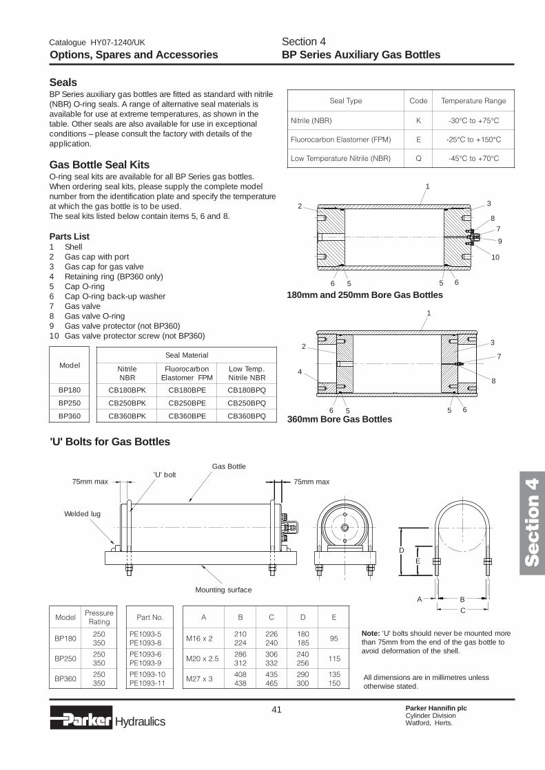
41 Parker Hannifin plcCylinder DivisionWatford, Herts.Hydraulics
Catalogue HY07-1240/UK
Options, Spares and AccessoriesSection 4BP Series Auxiliary Gas Bottles
'U' Bolts for Gas Bottles
Note: 'U' bolts should never be mounted morethan 75mm from the end of the gas bottle toavoid deformation of the shell.
All dimensions are in millimetres unlessotherwise stated.
SealsBP Series auxiliary gas bottles are fitted as standard with nitrile(NBR) O-ring seals. A range of alternative seal materials isavailable for use at extreme temperatures, as shown in thetable. Other seals are also available for use in exceptionalconditions – please consult the factory with details of theapplication.
Gas Bottle Seal KitsO-ring seal kits are available for all BP Series gas bottles.When ordering seal kits, please supply the complete modelnumber from the identification plate and specify the temperatureat which the gas bottle is to be used.The seal kits listed below contain items 5, 6 and 8.
Parts List1 Shell2 Gas cap with port3 Gas cap for gas valve4 Retaining ring (BP360 only)5 Cap O-ring6 Cap O-ring back-up washer7 Gas valve8 Gas valve O-ring9 Gas valve protector (not BP360)10 Gas valve protector screw (not BP360)
180mm and 250mm Bore Gas Bottles
360mm Bore Gas Bottles
4
1
23
8
5 6
7
1
2 3
8
5 6
7
9
10
Welded lug
75mm max
Mounting surface
75mm max
Gas Bottle'U' bolt
A B
C
D
E Secti
on 4
6 5
6 5
epyTlaeS edoC egnaRerutarepmeT
)RBN(elirtiN K C°57+otC°03-
)MPF(remotsalEnobracoroulF E C°051+otC°52-
)RBN(elirtiNerutarepmeTwoL Q C°07+otC°54-
ledoM
081PB
052PB
063PB
lairetaMlaeS
elirtiNRBN
nobracoroulFMPFremotsalE
.pmeTwoLRBNelirtiN
KPB081BC EPB081BC QPB081BC
KPB052BC EPB052BC QPB052BC
KPB063BC EPB063BC QPB063BC
ledoMerusserP
gnitaR
081PB052053
052PB052053
063PB052053
.oNtraP
5-3901EP8-3901EP
6-3901EP9-3901EP
01-3901EP11-3901EP
A B C D E
2x61M012422
622042
081581
59
5.2x02M682213
603233
042652
511
3x72M804834
534564
092003
531051
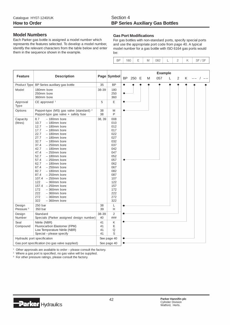
42 Parker Hannifin plcCylinder DivisionWatford, Herts.Hydraulics
Catalogue HY07-1240/UK
Gas Port ModificationsFor gas bottles with non-standard ports, specify special portsand use the appropriate port code from page 40. A typicalmodel number for a gas bottle with ISO 6164 gas ports wouldbe:
Model NumbersEach Parker gas bottle is assigned a model number whichrepresents the features selected. To develop a model number,identify the relevant characters from the table below and enterthem in the sequence shown in the example.
Product Type BP Series auxiliary gas bottle 35 BP
Model 180mm bore 38-39 180250mm bore 250360mm bore 360
Approval CE approved 1 5 EType
Options Poppet-type (MS) gas valve (standard) 2 38 MPoppet-type gas valve + safety fuse 38 P
Capacity 8.7 – 180mm bore 38, 39 008(litres) 10.7 – 180mm bore 010
12.7 – 180mm bore 01217.7 – 180mm bore 01722.7 – 180mm bore 02227.7 – 180mm bore 02732.7 – 180mm bore 03237.4 – 250mm bore 03742.7 – 180mm bore 04247.4 – 250mm bore 04752.7 – 180mm bore 05257.4 – 250mm bore 05762.7 – 180mm bore 06267.4 – 250mm bore 06782.7 – 180mm bore 08287.4 – 250mm bore 087107.4 – 250mm bore 107122 – 360mm bore 122157.4 – 250mm bore 157172 – 360mm bore 172222 – 360mm bore 222272 – 360mm bore 272322 – 360mm bore 322
Design 250 bar 38 LPressure 3 350 bar 39 H
Design Standard 38-39 2Number Specials (Parker assigned design number) 40 ###
Seal Nitrile (NBR) 41 KCompound Fluorocarbon Elastomer (FPM) 41 E
Low Temperature Nitrile (NBR) 41 QSpecial – please specify 41 S
Hydraulic port specification See page 40
Gas port specification (no gas valve supplied) See page 40
Feature Description Page SymbolExample
BP 250 E M 057 L 2 K – – / – –
How to OrderSection 4BP Series Auxiliary Gas Bottles
1 Other approvals are available to order – please consult the factory.2 Where a gas port is specified, no gas valve will be supplied.3 For other pressure ratings, please consult the factory.
PB 081 E M 280 L 2 K FS/FS
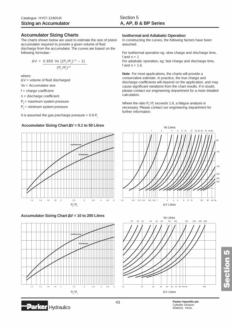
43 Parker Hannifin plcCylinder DivisionWatford, Herts.Hydraulics
Catalogue HY07-1240/UK
Sizing an Accumulator A, AP, B & BP SeriesSection 5
Accumulator Sizing ChartsThe charts shown below are used to estimate the size of pistonaccumulator required to provide a given volume of fluiddischarge from the accumulator. The curves are based on thefollowing formulae:-
∆V = 0.855 Vo [(P2/P
1)1/n – 1]
(P2/P
1)1/f
where:∆V = volume of fluid discharged
Vo = Accumulator size
f = charge coefficient
n = discharge coefficient
P2 = maximum system pressure
P1 = minimum system pressure
It is assumed the gas precharge pressure = 0.9 P1
Isothermal and Adiabatic OperationIn constructing the curves, the following factors have beenassumed.
For isothermal operation eg: slow charge and discharge time,f and n = 1For adiabatic operation, eg: fast charge and discharge time,f and n = 1.6.
Note For most applications, the charts will provide aconservative estimate. In practice, the true charge anddischarge coefficients will depend on the application, and maycause significant variations from the chart results. If in doubt,please contact our engineering department for a more detailedcalculation.
Where the ratio P2/ P
1 exceeds 1.9, a fatigue analysis is
necessary. Please contact our engineering department forfurther information.
P2/P
1∆V Litres
Vo LitresAccumulator Sizing Chart ∆∆∆∆∆V = 10 to 200 Litres
Secti
on 5
P2/ P
1∆V Litres
Vo LitresAccumulator Sizing Chart ∆∆∆∆∆V = 0.1 to 50 Litres

44 Parker Hannifin plcCylinder DivisionWatford, Herts.Hydraulics
Catalogue HY07-1240/UK
Cylinder DivisionSales Offices
198
Austria – MarchtrenkParker Hannifin GmbHTel: (7242) 56921Fax: (7242) 5692120
Belgium – NivellesParker Hannifin SA NVTel: 67 280 900Fax: 67 280 999
Czech Republic – PragueParker Hannifin CorporationTel: (02) 830 85 221Fax: (02) 830 85 360
Denmark – IshøjParker Hannifin Danmark A/STel: 43 56 04 00Fax: 43 73 31 07
Finland – VantaaParker Hannifin OyTel: 9 476 731Fax: 9 476 73200
France – Contamine-sur-ArveParker Hannifin SATel: 4 50 25.80.25Fax: 4 50 03.67.37
Germany – CologneParker Hannifin GmbHTel: (221) 71720Fax: (221) 7172219
Hungary – BudapestParker Hannifin Corp.Tel + Fax: 1 252 2539
Italy – Arsago-SeprioParker Hannifin S.p.A.Tel: (331) 765611Fax: (331) 765612
Netherlands – OldenzaalParker Hannifin B.V.Tel: (0) 541 585000Fax: (0) 541 585459
Norway – SkiParker Hannifin A/STel: (64) 91 10 00Fax: (64) 91 10 90
Poland – WarsawParker Hannifin Corp.Tel: (22) 863 49 42Fax: (22) 863 49 44
Portugal – Leca da PalmeiraParker Hannifin Portugal Lda.Tel: (22) 999 7360Fax: (22) 996 1527
Spain – MadridParker Hannifin Espana S.A.Tel: (91) 675 73 00Fax: (91) 675 77 11
Sweden – SpångaParker Hannifin AB.Tel: 08 5979 50 00Fax: 08 5979 51 20
Switzerland – RomanshornHydrel A.G. RomanshornTel: (714) 66 66 66Fax: (714) 66 63 33
Turkey – IstanbulHidroser Hidrolik - PnömatikTel: (212) 886 72 70Fax: (212) 886 69 35
United Kingdom – WatfordParker Hannifin PlcTel: (01923) 492000Fax: (01923) 248557
Hydraulics
1240/30101
Visit us at www.parker.com/uk
Need a Parker part?Call Parker's European Product Information Centreon 00800 27 27 5374