industrial it quality control 4 - abb download center
TRANSCRIPT

Industrial IT Quality Control 4.0 powered by 800xA extended automation
Theory of Operation Guide
System Version 4.0
3BUS208222 R4001 i

NOTICE
The information in this document is subject to change without notice and should not be construed as a commitment by ABB. ABB assumes no responsibility for any errors that may appear in this document.
In no event shall ABB be liable for direct, indirect, special, incidental or consequential damages of any nature or kind arising from the use of this document, nor shall ABB be liable for incidental or consequential damages arising from use of any software or hardware described in this document.
This document and parts thereof must not be reproduced or copied without written permission from ABB, and the contents thereof must not be imparted to a third party nor used for any unauthorized purpose.
The software or hardware described in this document is furnished under a license and may be used, copied, or disclosed only in accordance with the terms of such license.
This product meets the requirements specified in EMC Directive 89/336/EEC and in Low Voltage Directive 72/23/EEC.
Copyright © 2005 ABB
All rights reserved.
Release: January 2005
Document Number: 3BUS208222 R4001
ii 3BUS208222 R4001

TRADEMARKS
Registrations and trademarks used in this document include:
• Windows is a registered trademark of Microsoft Corporation.
• Acrobat Reader is a registered trademark of Adobe Systems Inc.
• IndustrialIT is a trademark of ABB.
3BUS208222 R4001 iii

About This Book
General This book describes the theory of operation and troubleshooting tools and procedures for Industrial IT Quality Control 4.0. The targeted audience includes ABB Project and Service engineers. The user of this guide is expected to have experience with ABB IndustrialIT products and the Industrial IT Quality Control 4.0 and to have attended the appropriate training courses.
Intended User
Use of Warning, Caution, Information, and Tip Icons This publication includes Warning, Caution, and Information where appropriate to point out safety related or other important information. It also includes Tip to point out useful hints to the reader. The corresponding symbols should be interpreted as follows:
Electrical warning icon indicates the presence of a hazard, which could result in electrical shock.
Warning icon indicates the presence of a hazard, which could result in personal injury.
Caution icon indicates important information or warning related to the concept discussed in the text. It might indicate the presence of a hazard, which could result incorruption of software or damage to equipment/property.
Information icon alerts the reader to pertinent facts and conditions.
Tip icon indicates advice on, for example, how to design your project or how to use a certain function.
Although Warning hazards are related to personal injury, and Caution hazards are associated with equipment or property damage, it should be understood that operation of damaged equipment could, under certain operational conditions, result in degraded process performance leading to personal injury or death. Therefore, comply fully with all Warning and Caution notices.
iv 3BUS208222 R4001

Document Conventions The following conventions are used for the presentation of material:
1. The words in names of screen elements (for example, the title in the title bar of a window, the label for a field of a dialog box) are initially capitalized.
2. Capital letters are used for the name of a keyboard key if it is labeled on the keyboard. For example, press the “ENTER” key.
3. Lowercase letters are used for the name of a keyboard key that is not labeled on the keyboard. For example, the “space bar”, “comma” key, and so on.
4. Press “CTRL+C” indicates that you must hold down the “CTRL” key while pressing the “C” key. In this case, “CTRL+C” copies the selected object.
5. Press “ESC E C” indicates that you press and release each key in sequence. In this case, “ESC E C” copies the selected object.
6. The names of push and toggle buttons are boldfaced. For example, click “OK”.
7. The names of menus and menu items are boldfaced. For example, the “File Menu”.
8. The following convention is used for menu operations: “MenuName > MenuItem > CascadedMenuItem”. For example: select “File > New > Type”.
9. The “Start menu” name always refers to the “Start” menu on the Windows Task Bar.
10. System prompts or messages are shown in the Courier font. For example, if the user enters a value out of range, the system might reply with the following message:
Entered value is not valid. The value must be 0 to 30.
11. User responses or inputs are shown in the boldfaced Courier font. For example, a user may be required to enter the string “TIC132” in a field. The string is shown as follows in the procedure:
TIC132
12. Variables are shown using lowercase letters. sequence name
3BUS208222 R4001 v

Terminology The following is a list of terms associated with the Theory of Operation Guide that you should be familiar with. The list contains terms and abbreviations that are unique to ABB or have a usage or definition that is different from standard industry usage.
Term Description
ActiveX Microsoft standard for integration of user interface components, based on definition of software interfaces.
Aspect An aspect is a description of some properties of a real world entity. The properties described could be mechanical layout, how the object is controlled, a live video image, name of the object etc. In the Aspect Integrator Platform is an aspect residing in an Aspect Object. Some examples are circuit diagram, process display, and control logic.
Aspect Objects A computer representation of a real world entity like a pump, a valve, an order or a virtual object like a service. This computer representation is implemented by the Aspect Integrator Platform. An Aspect Object works like an information container for its aspects.
Aspect Server PC server that hosts the various QCS Object/Aspects and serves as the primary gateway to external aspects systems.
Connectivity Server
PC server that hosts MeasureIT and ControlIT applications and serves as the primary “connection” between the QCS LAN and the outside world.
IndustrialIT IndustrialIT is ABB’s solution, that creates a business enterprise where your plant automation, asset optimization, and collaborative business systems are seamlessly linked in real time.
Industrial IT Quality Control 4.0
ABB’s Quality Control Solution consisting of MeasureIT Scanners/Sensors, ControlIT controllers (AC450, AC800M, and/or PC), ProfileIT actuators, OperateIT Process Portal consoles, and MeasureIT /ControlIT software applications. Integrated with Pulp and Paper Making Suite 3.0.
Node A computer communicating an a network e.g. the Internet, Plant, Control or IO network. Each node typically has a unique node address with a format depending on the network it is connected to.
OPC An application programming interface defined by the OPC Foundation. The standard defines how to access large amounts of real-time data between applications. The OPC standard interface is used between automation/control applications, field system/devices and business/office applications.
OperateIT The name for the collection of products for daily operation and supervision of an automated process.
Plant Explorer An application that is used to create, delete and organize Aspect Objects and Aspects within the Aspect Integrator Platform. The plant explorer organizes the Aspect Objects in structures of the plant.
Process Portal A Product containing functionality for efficient control and supervision of an automated process. Key functions are presentation of process graphics, process dialogs and presentation of alarms and trends.
vi 3BUS208222 R4001
Term Description
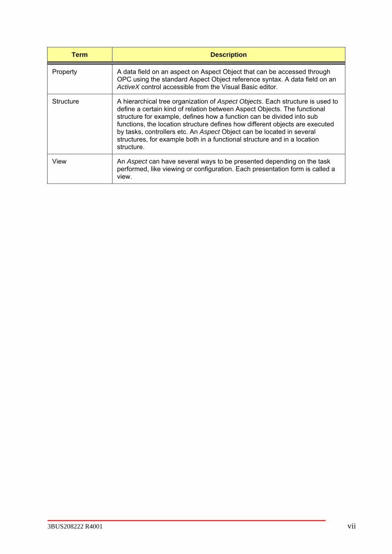
Property A data field on an aspect on Aspect Object that can be accessed through OPC using the standard Aspect Object reference syntax. A data field on an ActiveX control accessible from the Visual Basic editor.
Structure A hierarchical tree organization of Aspect Objects. Each structure is used to define a certain kind of relation between Aspect Objects. The functional structure for example, defines how a function can be divided into sub functions, the location structure defines how different objects are executed by tasks, controllers etc. An Aspect Object can be located in several structures, for example both in a functional structure and in a location structure.
View An Aspect can have several ways to be presented depending on the task performed, like viewing or configuration. Each presentation form is called a view.
3BUS208222 R4001 vii

Abbreviations Term Description
CD Compact Disk
CPU Central Processing Unit
DHCP Dynamic Host Configuration Protocol
DNS Domain Name Server
DPI Dots per inch
GB GB Gigabyte
IP address Internet Protocol address
MB Megabyte
Mbps Megabits per second
MHz Megahertz
NetBIOS Network Basic Input Output System
NTFS NT File System
OEM Original Equipment Manufacturing
OPC OLE for Process Control
OLE Object Linking and Embedding
OS Operating System
PC Personal Computer
RAM Random Access Memory
SCSI Small Computer System Interface
SVGA Super Video Graphics Adapter
TCP/IP Transmission Control Protocol/Internet Protocol
WINS Windows Internet Name Services
viii 3BUS208222 R4001

Related Documentation Category Title Description
Industrial IT, 800xA System Version 4.0, Automated Installation
3BSE034679R4001
Industrial IT, 800xA System Version 4.0, Installation
3BSE034678R4001
Industrial IT, 800xA System Version 4.0, Upgrade and Installation
3BSE036342R4001
800xA System Installation
Industrial IT, 800xA System Version 4.0, Post Installation Setup
3BUA000156R4001
800xA System Administration
Industrial IT, 800xA System, Administration and Security
3BSE037410R4001
Industrial IT, 800xA System, Automation System Network Design and Configuration
3BSE034463R4001
Industrial IT, 800xA System, System Guide
3BSE038018R4001
800xA Software
Industrial IT, 800xA System, Release Notes
3BSE038357R4001
Industrial IT Quality Control 4.0, Installation Guide
3BUS208220R4001 -This book describes how you install the Industrial IT Quality Control 4.0
Industrial IT Quality Control 4.0, Upgrade Guide
3BUS208226R4001 -This book describes how you upgrade from Industrial IT Quality Control 3.0 to Industrial IT Quality Control 4.0
Industrial IT Quality Control 4.0, Administrator’s Guide
3BUS208217R4001 - This book describes how you configure the Industrial IT Quality Control 4.0 application and how you then perform maintenance.
Industrial IT Quality Control 4.0, Operations User Guide
3BUS208221R4001 - This book describes how an operator can control and operate Industrial IT Quality Control 4.0.
Industrial IT Quality Control 4.0, Engineering Methods Reference Manual
3BUS208218R4001 - This book is a guide for plant engineering functions related to Industrial IT Quality Control 4.0.
Industrial IT Quality Control 4.0 Installation
Industrial IT Quality Control 4.0, Theory of Operation Guide
3BUS208222R4001 - This book describes the theory of operation for Industrial IT Quality Control 4.0 and provides troubleshooting guidance.
3BUS208222 R4001 ix

Category Title Description
Industrial IT Quality Control 4.0, CD Tuning Guide
3BUS208224R4001 - This book describes how to setup and tune the Industrial IT Quality Control 4.0 CD Control feature.
Industrial IT Quality Control 4.0, MD Tuning Guide
3BUS208223R4001 - This book describes how to setup and tune the Industrial IT Quality Control 4.0 MD Control features.
Industrial IT Quality Control 4.0, Service Workstation Getting Started Manual
3BUS208230R4001 - This book describes how to install and configure the Industrial IT Quality Control 4.0 Smart Platform Service Workstation
Industrial IT Quality Control 4.0, Coat Weight & Computed Sensors Manual
3BUS208229R4001 - This book describes how to configure and verify coat weight, calculated measurements and synchronized scanning.
Industrial IT Quality Control 4.0, Color Control Guide
3BUS208227R4001 - This book describes how to configure, verify and tune Color Controls.
Industrial IT Quality Control 4.0, Multi-Ply Controls Tuning Guide
3BUS208228R4001 - This book describes how to configure, verify and tune Multi-Ply Controls.
Industrial IT Quality Control 4.0 Features
Industrial IT Quality Control 4.0, Color Measurement Operations Use Guide
3BUS208232R4001 - This book describes how to operate Color Measurement.
x 3BUS208222 R4001
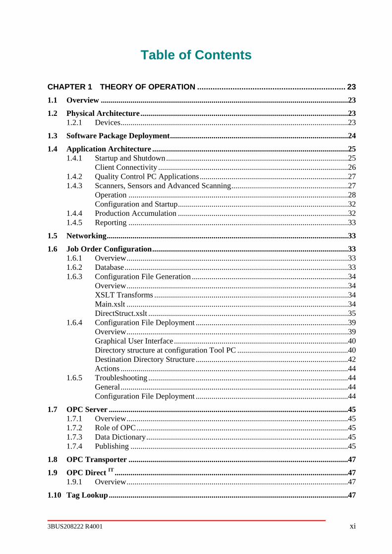
Table of Contents
CHAPTER 1 THEORY OF OPERATION ................................................................... 23
1.1 Overview .............................................................................................................................23
1.2 Physical Architecture.........................................................................................................23 1.2.1 Devices...................................................................................................................23
1.3 Software Package Deployment..........................................................................................24
1.4 Application Architecture ...................................................................................................25 1.4.1 Startup and Shutdown............................................................................................25
Client Connectivity ................................................................................................26 1.4.2 Quality Control PC Applications...........................................................................27 1.4.3 Scanners, Sensors and Advanced Scanning...........................................................27
Operation ...............................................................................................................28 Configuration and Startup......................................................................................32
1.4.4 Production Accumulation ......................................................................................32 1.4.5 Reporting ...............................................................................................................33
1.5 Networking..........................................................................................................................33
1.6 Job Order Configuration...................................................................................................33 1.6.1 Overview................................................................................................................33 1.6.2 Database.................................................................................................................33 1.6.3 Configuration File Generation ...............................................................................34
Overview................................................................................................................34 XSLT Transforms ..................................................................................................34 Main.xslt ................................................................................................................34 DirectStruct.xslt .....................................................................................................35
1.6.4 Configuration File Deployment .............................................................................39 Overview................................................................................................................39 Graphical User Interface........................................................................................40 Directory structure at configuration Tool PC ........................................................40 Destination Directory Structure .............................................................................42 Actions ...................................................................................................................44
1.6.5 Troubleshooting .....................................................................................................44 General...................................................................................................................44 Configuration File Deployment .............................................................................44
1.7 OPC Server .........................................................................................................................45 1.7.1 Overview................................................................................................................45 1.7.2 Role of OPC...........................................................................................................45 1.7.3 Data Dictionary......................................................................................................45 1.7.4 Publishing ..............................................................................................................45
1.8 OPC Transporter ...............................................................................................................47
1.9 OPC Direct IT ......................................................................................................................47 1.9.1 Overview................................................................................................................47
1.10 Tag Lookup.........................................................................................................................47
3BUS208222 R4001 xi

1.10.1 Overview................................................................................................................47 1.10.2 Usage......................................................................................................................50 1.10.3 Configuration .........................................................................................................50
Startup.xml.............................................................................................................50 HSI server XML file ..............................................................................................52 HSI tags XML file .................................................................................................53 Revision ID (RevID)..............................................................................................54
1.10.4 Troubleshooting .....................................................................................................54 Task Manager ........................................................................................................55 Debug Message Viewer (ABB Debug Client).......................................................55 Windows Event Viewer .........................................................................................55 OPC Direct IT View................................................................................................55 OPC Inspector........................................................................................................55 TagLookUp Viewer ...............................................................................................55
1.11 Startup Engine....................................................................................................................57 1.11.1 Overview................................................................................................................57 1.11.2 Usage......................................................................................................................57 1.11.3 Configuration .........................................................................................................57
1.12 System Status Reporting....................................................................................................57 1.12.1 Overview................................................................................................................57 1.12.2 Configuration .........................................................................................................57
1.13 DCOM .................................................................................................................................58 1.13.1 Overview................................................................................................................58 1.13.2 Usage......................................................................................................................58 1.13.3 Configuration .........................................................................................................58
CHAPTER 2 ASPECTS AND OBJECTS................................................................... 60
2.1 Overview .............................................................................................................................60
2.2 Object Type Structure .......................................................................................................60
2.3 Aspect categories and Filtering.........................................................................................60
2.4 Quality control aspect functionality .................................................................................61
2.5 Process Graphics ................................................................................................................62 2.5.1 Overview................................................................................................................62 2.5.2 Tag Lookup............................................................................................................62
2.6 Grade Code Handling ........................................................................................................62 2.6.1 Overview................................................................................................................62 2.6.2 Usage......................................................................................................................62 2.6.3 Configuration .........................................................................................................62
2.7 Coldstart File Handling .....................................................................................................62 2.7.1 Overview................................................................................................................62 2.7.2 Usage......................................................................................................................62 2.7.3 Configuration .........................................................................................................62
2.8 MD Control .........................................................................................................................62 2.8.1 Overview................................................................................................................62 2.8.2 Configuration .........................................................................................................63
xii 3BUS208222 R4001

AC800M Control Project.......................................................................................63 AC800M Control Libraries....................................................................................63 Operator Interface Configuration...........................................................................63 Default Tuning and Configuration Data ................................................................64 OPC Transporter Configuration.............................................................................64 Project Configuration File .....................................................................................64
2.8.3 Configuration Verification.....................................................................................65 2.8.4 Operation Verification ...........................................................................................67
2.9 CD Control..........................................................................................................................69 2.9.1 Overview................................................................................................................69 2.9.2 Application Framework Dependencies..................................................................70
ABB QCS Service..................................................................................................70 OPC Publishing......................................................................................................70 OPC Transporter Service .......................................................................................71 TagsLookup ...........................................................................................................71 ABB Health Watch ................................................................................................73
2.9.3 Configuration .........................................................................................................74 Required Job Order Information............................................................................74 Deployment Directory Structure............................................................................75 XML Documents ...................................................................................................76
2.9.4 Interface to Dependent Application.......................................................................77 Frame and Sensor Transporters .............................................................................77 Actuator Transporters ............................................................................................78 Grade Data Transporter .........................................................................................78
2.9.5 Verify Configuration and Operation......................................................................79 QC Server Node.....................................................................................................79 Process Portal Functional Structure.......................................................................80 Error/Event Log File ..............................................................................................81
2.10 CD Control Coater Operation ..........................................................................................82 2.10.1 Overview................................................................................................................82 2.10.2 Application Framework Dependencies..................................................................82
ABB QCS Service..................................................................................................82 OPC Publishing......................................................................................................83 OPC Transporter Service .......................................................................................83 TagsLookup ...........................................................................................................84 ABB HealthWatch .................................................................................................84
2.10.3 Configuration .........................................................................................................85 Required Job Order Information............................................................................85 Deployment Directory Structure............................................................................86 XML Documents ...................................................................................................86
2.10.4 Interface to Dependent Application.......................................................................87 CD Control.............................................................................................................87 Grade Data .............................................................................................................87
2.10.5 Verify Configuration and Operation......................................................................88 QC Server Node.....................................................................................................88 Process Portal Functional Structure.......................................................................89 Error/Event Log File ..............................................................................................90
2.11 Local Variability (LV) Control .........................................................................................91
3BUS208222 R4001 xiii

2.11.1 Overview................................................................................................................91 2.11.2 Application Framework Dependencies..................................................................91
ABB QCS Service..................................................................................................91 OPC Publishing......................................................................................................92 OPC Transporter Service .......................................................................................92 TagsLookup ...........................................................................................................92 ABB HealthWatch .................................................................................................94
2.11.3 Configuration .........................................................................................................94 Required Job Order Information............................................................................94 Deployment Directory Structure............................................................................95 XML Documents ...................................................................................................95
2.11.4 Interface to Dependent Application.......................................................................96 2.11.5 Verify Configuration and Operation......................................................................96
QC Server Node.....................................................................................................96 Process Portal Functional Structure.......................................................................98 Error/Event Log File ..............................................................................................98
2.12 CD Actuator Agent.............................................................................................................99 2.12.1 Overview................................................................................................................99 2.12.2 Application Framework Dependencies..................................................................99
ABB QCS Service..................................................................................................99 OPC Publishing....................................................................................................100 OPC Transporter Service .....................................................................................100 TagsLookup .........................................................................................................101
2.12.3 Configuration .......................................................................................................101 Required Job Order Information..........................................................................101 Deployment Directory Structure..........................................................................103 XML Documents .................................................................................................104
2.12.4 Interface to Dependent Application.....................................................................105 2.12.5 Verify Configuration and Operation....................................................................105
QC Server Node...................................................................................................105 Process Portal Functional Structure.....................................................................107 Error/Event Log File ............................................................................................108
CHAPTER 3 TROUBLESHOOTING ........................................................................ 110
3.1 Quality Control Diagnostics Aspect................................................................................110 3.1.1 Configuration .......................................................................................................110
3.2 Debug Message Viewer ....................................................................................................111 Key.......................................................................................................................111
3.2.2 Application Menu ................................................................................................112 Mode ....................................................................................................................112 Activity ................................................................................................................113
3.3 Windows Event Viewer....................................................................................................114
3.4 System Status Viewers .....................................................................................................114 3.4.1 Quality Control Status Viewer.............................................................................114 3.4.2 Nodes Status Viewer............................................................................................115 3.4.3 AC800M Controller Status Viewer .....................................................................115
3.5 License Viewer..................................................................................................................115
xiv 3BUS208222 R4001

3.6 Task Manager...................................................................................................................116
3.7 OPC Inspector ..................................................................................................................117
3.8 OPC Direct IT Viewer.......................................................................................................117 3.8.1 Top Window - Active OPC Server Monitors ......................................................118 3.8.2 Bottom Window – Active Data Points.................................................................119
3.9 Control Builder.................................................................................................................121
3.10 Measurement Spreadsheets.............................................................................................121
3.11 Service Workstation.........................................................................................................121
3.12 Performance Monitor ......................................................................................................121
3.13 Collecting Information for Technical Support..............................................................121 3.13.1 Information to Collect..........................................................................................121 3.13.2 How To ................................................................................................................122
Screen Captures ...................................................................................................122 Debug Message Viewer Contents........................................................................122 Event Log Contents .............................................................................................122
3.14 Trouble Shooting Flowcharts ..........................................................................................123
APPENDIX A. OPC TRANSPORTER ........................................................................ 128
A.1 Introduction ......................................................................................................................128 A.1.1Purpose ......................................................................................................................128 A.1.2Overview ...................................................................................................................128 A.1.3Limitations, Restrictions, Caveats.............................................................................128 A.1.4XML Basics...............................................................................................................128
A.2 Transporter File ...............................................................................................................129 A.2.1File Content ...............................................................................................................129 A.2.2Element Definitions...................................................................................................130
<transporter>........................................................................................................130 <sourceOPC> & <targetOPC> ............................................................................131 <group>................................................................................................................131 <branch> ..............................................................................................................132 <input> & <output>.............................................................................................133 <assign> ...............................................................................................................133 <quality >.............................................................................................................134 <timestamp> ........................................................................................................134 <transport >..........................................................................................................135 <breakArray>.......................................................................................................136 <makeArray> .......................................................................................................137 <breakFlag> .........................................................................................................138 <makeFlag> .........................................................................................................139 <trigger> & <triggeredBy>..................................................................................140 <watchdog> & <heartbeat> .................................................................................141 <sub> ...................................................................................................................142 <global> ...............................................................................................................144
A.2.3Data References.........................................................................................................145 Variable Name .....................................................................................................145
3BUS208222 R4001 xv

Data Type.............................................................................................................146 Arrays...................................................................................................................146
A.2.4Transporter Programming Language.........................................................................146 Comments ............................................................................................................146 Declarations .........................................................................................................146 Arithmetic Expressions........................................................................................147 Assignment Statement .........................................................................................148 If Statement..........................................................................................................148 Select Statement...................................................................................................148 Example <sub> Element ......................................................................................149
A.3 Operation ..........................................................................................................................149 A.3.1Invocation..................................................................................................................149 A.3.2Error recording ..........................................................................................................150
Event Log.............................................................................................................150 Debug modes .......................................................................................................150
A.3.3Error recovery............................................................................................................151
A.4 Document Type Definition...............................................................................................152
A.5 TPL Formal Definition ....................................................................................................154 A.5.1<program> ::= <declarations> <statements> ............................................................154
APPENDIX B. ACTIVEX CONTROLS LIST ............................................................... 156
B.1 Introduction ......................................................................................................................156
B.2 ActiveX Controls ..............................................................................................................156
APPENDIX C. TAGLOOKUP ACTIVEX CONTROLS ................................................ 163
C.1 Introduction ......................................................................................................................163
C.2 ABB Auto Grid .................................................................................................................163 C.2.1Introduction ...............................................................................................................163 C.2.2Functionality..............................................................................................................163
Supported Data Types..........................................................................................163 Visual Appearance ...............................................................................................163 Scalar AttriIDs only .............................................................................................163 Array AttriIDs only..............................................................................................164 Mixed scalar and array AttriIDs ..........................................................................164 Mixed AttriIDs within a TagID ...........................................................................164 User Interface.......................................................................................................165 Show OPC Tag ....................................................................................................166 Set Decimal Places...............................................................................................166 Export to Excel ....................................................................................................166 Copy Data to Clipboard .......................................................................................166 OperateIT context extension................................................................................166
C.2.3XML Configuration...................................................................................................167 XML Keywords ...................................................................................................167 Example Configuration........................................................................................168
C.2.4Dependencies.............................................................................................................169
C.3 ABB Auto Plot ..................................................................................................................169
xvi 3BUS208222 R4001

C.3.1Introduction ...............................................................................................................169 C.3.2Functionality..............................................................................................................170
Supported Plot Types and Data Requirements ....................................................170 User Interface.......................................................................................................178 Display Options Dialog .......................................................................................180 Rulers ...................................................................................................................182 Zooming and Scrolling ........................................................................................182 Stacking and Merging Plots .................................................................................183 Rearranging Plots.................................................................................................184
C.3.3XML Configuration...................................................................................................184 XML Keywords ...................................................................................................184 Example XML Configuration ..............................................................................188
C.3.4Dependencies.............................................................................................................189
C.4 ABB Command Button....................................................................................................190 C.4.1Introduction ...............................................................................................................190 C.4.2Functionality..............................................................................................................190
Basic XML Structure ...........................................................................................190 Properties .............................................................................................................190
C.4.3DisplayType...............................................................................................................190 C.4.4NumberOfButtons......................................................................................................191
XML Key Word...................................................................................................191 C.4.5RevID.........................................................................................................................191 C.4.6HelpID .......................................................................................................................191 C.4.7Resource ....................................................................................................................192 C.4.8Request ......................................................................................................................192 C.4.9State ...........................................................................................................................192 C.4.10Confirm, ConfirmRes ..............................................................................................192 C.4.11Writable, NotWritable .............................................................................................193
Right Click Menu.................................................................................................193 C.4.12Show OPC Tag ........................................................................................................193 C.4.13XML Keywords .......................................................................................................195 C.4.14Example of XML File..............................................................................................196
C.5 ABB Indicator Control ....................................................................................................196 C.5.1Introduction ...............................................................................................................196 C.5.2Functionality..............................................................................................................197
Basic XML Structure ...........................................................................................197 C.5.3XML Key Word.........................................................................................................197 C.5.4RevID.........................................................................................................................197 C.5.5HelpID .......................................................................................................................197 C.5.6Resource ....................................................................................................................198 C.5.7Value..........................................................................................................................198 C.5.8IndBackColor, IndForeColor.....................................................................................198 C.5.9ReverseFlag ...............................................................................................................198
Right Click Menu.................................................................................................199 C.5.10Show OPC Tag ........................................................................................................199 C.5.11Example of XML File..............................................................................................199
C.6 ABB CD Mapping Control ..............................................................................................200 C.6.1Introduction ...............................................................................................................200
3BUS208222 R4001 xvii
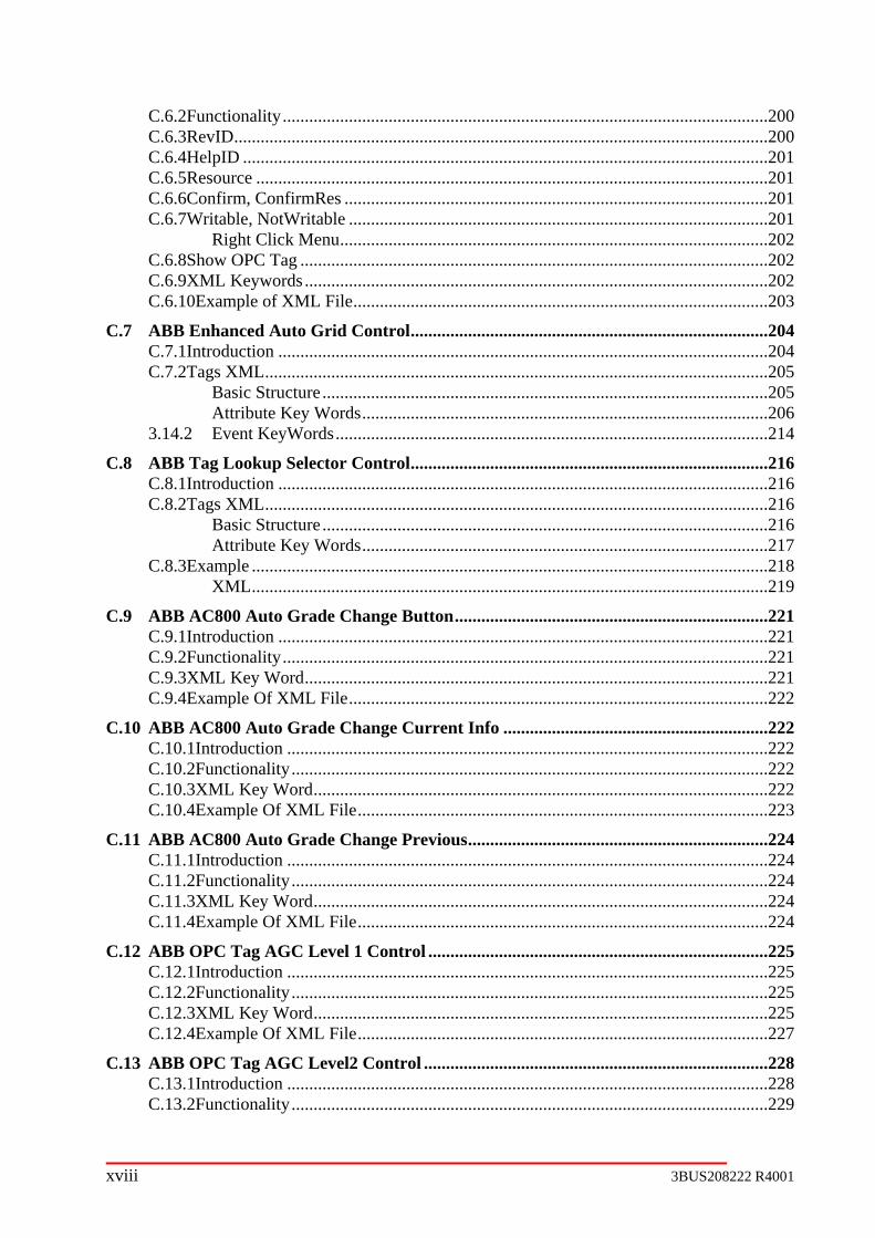
C.6.2Functionality..............................................................................................................200 C.6.3RevID.........................................................................................................................200 C.6.4HelpID .......................................................................................................................201 C.6.5Resource ....................................................................................................................201 C.6.6Confirm, ConfirmRes ................................................................................................201 C.6.7Writable, NotWritable ...............................................................................................201
Right Click Menu.................................................................................................202 C.6.8Show OPC Tag ..........................................................................................................202 C.6.9XML Keywords .........................................................................................................202 C.6.10Example of XML File..............................................................................................203
C.7 ABB Enhanced Auto Grid Control.................................................................................204 C.7.1Introduction ...............................................................................................................204 C.7.2Tags XML..................................................................................................................205
Basic Structure .....................................................................................................205 Attribute Key Words............................................................................................206
3.14.2 Event KeyWords..................................................................................................214
C.8 ABB Tag Lookup Selector Control.................................................................................216 C.8.1Introduction ...............................................................................................................216 C.8.2Tags XML..................................................................................................................216
Basic Structure .....................................................................................................216 Attribute Key Words............................................................................................217
C.8.3Example .....................................................................................................................218 XML.....................................................................................................................219
C.9 ABB AC800 Auto Grade Change Button.......................................................................221 C.9.1Introduction ...............................................................................................................221 C.9.2Functionality..............................................................................................................221 C.9.3XML Key Word.........................................................................................................221 C.9.4Example Of XML File...............................................................................................222
C.10 ABB AC800 Auto Grade Change Current Info ............................................................222 C.10.1Introduction .............................................................................................................222 C.10.2Functionality............................................................................................................222 C.10.3XML Key Word.......................................................................................................222 C.10.4Example Of XML File.............................................................................................223
C.11 ABB AC800 Auto Grade Change Previous....................................................................224 C.11.1Introduction .............................................................................................................224 C.11.2Functionality............................................................................................................224 C.11.3XML Key Word.......................................................................................................224 C.11.4Example Of XML File.............................................................................................224
C.12 ABB OPC Tag AGC Level 1 Control .............................................................................225 C.12.1Introduction .............................................................................................................225 C.12.2Functionality............................................................................................................225 C.12.3XML Key Word.......................................................................................................225 C.12.4Example Of XML File.............................................................................................227
C.13 ABB OPC Tag AGC Level2 Control ..............................................................................228 C.13.1Introduction .............................................................................................................228 C.13.2Functionality............................................................................................................229
xviii 3BUS208222 R4001

C.13.3XML Key Word.......................................................................................................229 C.13.4Example Of XML File.............................................................................................231
C.14 ABB OPC Tag Level 1 singleline ....................................................................................232 C.14.1Introduction .............................................................................................................232 C.14.2Functionality............................................................................................................233 C.14.3XML Key Word.......................................................................................................233 C.14.4Example Of XML File.............................................................................................235
C.15 ABB OPC Tag Level 1 grid .............................................................................................235 C.15.1Introduction .............................................................................................................235 C.15.2Functionality............................................................................................................236 C.15.3XML Key Word.......................................................................................................236 C.15.4Example Of XML File.............................................................................................238
C.16 ABB OPC Tag Level 1 Vertical ......................................................................................239 C.16.1Introduction .............................................................................................................239 C.16.2Functionality............................................................................................................240 C.16.3XML Key Word.......................................................................................................240 C.16.4Example Of XML File.............................................................................................242
C.17 ABB OPC Tag Level 2 singleline ....................................................................................242 C.17.1Introduction .............................................................................................................242 C.17.2Functionality............................................................................................................243 C.17.3XML Key Word.......................................................................................................243 C.17.4Example Of XML File.............................................................................................246
C.18 ABB OPC Tag Level 2 grid .............................................................................................246 C.18.1Introduction .............................................................................................................246 C.18.2Functionality............................................................................................................246 C.18.3XML Key Word.......................................................................................................246 C.18.4Example Of XML File.............................................................................................249
C.19 ABB OPC Tag Speed Control .........................................................................................250 C.19.1Introduction .............................................................................................................250 C.19.2Functionality............................................................................................................250 C.19.3XML Key Word.......................................................................................................250 C.19.4Example Of XML File.............................................................................................253
3BUS208222 R4001 xix

List of Figures Figure 1-1 Example system architecture ............................................................................................ 24 Figure 1-2 Software component architecture with example installation components ........................ 25 Figure 1-3 Quality Control Application Architecture Overview............................................................ 26 Figure 1-4 Main.xslt flow chart ............................................................................................................ 35 Figure 1-5 Batch file location for Job Order configuration .................................................................. 40 Figure 1-6 After configuring system chose Deploy Job button ........................................................... 40 Figure 1-7 Directory structure on configuration tool PC ..................................................................... 40 Figure 1-8 - Quality Control Object Server Overview ......................................................................... 46 Figure 1-9 Tag Lookup flowchart on server ........................................................................................ 49 Figure 1-10 Tag Lookup on client ....................................................................................................... 50 Figure 1-11 Tags XML Information Pop-up contains tag look-up information for the system ............ 56 Figure 1-12 Scanner Object Setup ..................................................................................................... 58 Figure 2-1 Object Type Structure example......................................................................................... 60 Figure 2-2: Example of MD Project Create Tool Message for Variable Name Discrepancy.............. 65 Figure 2-3: Example of Status Viewer ................................................................................................ 66 Figure 2-4: Example of MD Objects in Functional Structure .............................................................. 66 Figure 2-5: Example of MD Objects in Control Structure ................................................................... 67 Figure 2-6: Simulation Configuration .................................................................................................. 68 Figure 2-7: Example Faceplate........................................................................................................... 68 Figure 2-8: Example Right Click Menu ............................................................................................... 69 Figure 2-9: CD control job order configuration tab ............................................................................ 75 Figure 2-10: ABB Debug Client for startup of CD control .................................................................. 80 Figure 2-11: Status viewer example for CD control ........................................................................... 81 Figure 2-12: Functional structure example for CD Control ................................................................ 81 Figure 2-13: CD control job order configuration tab with “CD Coat Weight” as an option for the “CD
Type” ............................................................................................................................................ 85 Figure 2-14: ABB Debug Client for startup of CDCTW...................................................................... 89 Figure 2-15: Status viewer example for CDCTW............................................................................... 90 Figure 2-16: CD control job order configuration tab with LVC checkbox........................................... 94 Figure 2-17: ABB Debug Client for startup of LVC ............................................................................ 98 Figure 2-18: Status viewer example for LVC ..................................................................................... 98 Figure 2-19: CD actuator agent job order configuration tab ............................................................. 103 Figure 2-20: ABB Debug Client for startup of CD actuator agent.................................................... 107 Figure 2-21: Status viewer example for CD actuator agent............................................................. 108 Figure 2-22: Functional structure example for CD actuator agents................................................. 108 Figure 3-1 Quality Control Diagnostics Aspect in the Functional Structure...................................... 110 Figure 3-2 Quality Control Diagnostics Example Display ................................................................. 110 Figure 3-3 Debug Message Viewer Tool example ........................................................................... 111 Figure 3-4 Toolbar icons functionality ............................................................................................... 112 Figure 3-5 Available Application Debug Mode Selection for Scanner.............................................. 112 Figure 3-6 Available Application Debug Mode Selection for OPC Transporter................................ 113 Figure 3-7 Application Activity status properties for Measurement Basis Weight ............................ 113 Figure 3-8 Application Activity status properties for OPC Transporter ............................................. 113 Figure 3-9 Windows application log on Event Viewer ...................................................................... 114 Figure 3-10 Quality Control Status Viewer example......................................................................... 115 Figure 3-11 License Manager Utility ................................................................................................. 116 Figure 3-12 Windows Task Manager aids in troubleshooting .......................................................... 117 Figure 3-13 OPC Direct IT Viewer .................................................................................................... 118 Figure 3-14 OPC Direct IT Viewer Top Area .................................................................................... 118 Figure 3-15 OPC Direct IT Viewer Bottom Area ............................................................................... 119 Figure 3-16 OPC Direct IT buttons ................................................................................................... 120 Figure 3-17 OPC Direct IT Configuration........................................................................................... 121 Figure 3-18 Windows message with OPC Server and tag information ............................................ 166 Figure 3-19 Set decimal places using Windows pop-up................................................................... 166 Figure 3-20 Target dialog pop-up ..................................................................................................... 173 Figure 3-21 Actuator profile modes and setpoints pop-up................................................................ 175 Figure 3-22 Reflected Plot example.................................................................................................. 176
xx 3BUS208222 R4001
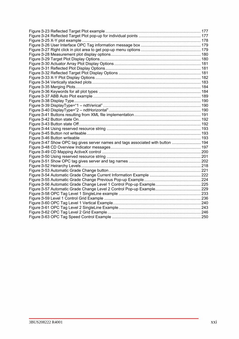
Figure 3-23 Reflected Target Plot example ...................................................................................... 177 Figure 3-24 Reflected Target Plot pop-up for individual points ........................................................ 177 Figure 3-25 X-Y plot example ........................................................................................................... 178 Figure 3-26 User Interface OPC Tag information message box ...................................................... 179 Figure 3-27 Right click in plot area to get pop-up menu options ...................................................... 179 Figure 3-28 Measurement plot display options................................................................................. 180 Figure 3-29 Target Plot Display Options........................................................................................... 180 Figure 3-30 Actuator Array Plot Display Options .............................................................................. 181 Figure 3-31 Reflected Plot Display Options...................................................................................... 181 Figure 3-32 Reflected Target Plot Display Options .......................................................................... 181 Figure 3-33 X-Y Plot Display Options ............................................................................................... 182 Figure 3-34 Vertically stacked plots .................................................................................................. 183 Figure 3-35 Merging Plots................................................................................................................. 184 Figure 3-36 Keywords for all plot types ............................................................................................ 184 Figure 3-37 ABB Auto Plot example ................................................................................................. 189 Figure 3-38 Display Type.................................................................................................................. 190 Figure 3-39 DisplayType=“1 – ndtVerical” ........................................................................................ 190 Figure 3-40 DisplayType=”2 – ndtHorizontal” ................................................................................... 190 Figure 3-41 Buttons resulting from XML file implementation............................................................ 191 Figure 3-42 Button state On.............................................................................................................. 192 Figure 3-43 Button state Off.............................................................................................................. 192 Figure 3-44 Using reserved resource string ..................................................................................... 193 Figure 3-45 Button not writeable....................................................................................................... 193 Figure 3-46 Button writeable............................................................................................................. 193 Figure 3-47 Show OPC tag gives server names and tags associated with button .......................... 194 Figure 3-48 CD Overview Indicator messages................................................................................. 197 Figure 3-49 CD Mapping ActiveX control ......................................................................................... 200 Figure 3-50 Using reserved resource string ..................................................................................... 201 Figure 3-51 Show OPC tag gives server and tag names ................................................................. 202 Figure 3-52 Heirarchy Levels............................................................................................................ 218 Figure 3-53 Automatic Grade Change button................................................................................... 221 Figure 3-54 Automatic Grade Change Current Information Example .............................................. 222 Figure 3-55 Automatic Grade Change Previous Pop-up Example................................................... 224 Figure 3-56 Automatic Grade Change Level 1 Control Pop-up Example......................................... 225 Figure 3-57 Automatic Grade Change Level 2 Control Pop-up Example......................................... 229 Figure 3-58 OPC Tag Level 1 SingleLine example .......................................................................... 233 Figure 3-59 Level 1 Control Grid Example ....................................................................................... 236 Figure 3-60 OPC Tag Level 1 Vertical Example............................................................................... 240 Figure 3-61 OPC Tag Level 2 SingleLine Example .......................................................................... 243 Figure 3-62 OPC Tag Level 2 Grid Example .................................................................................... 246 Figure 3-63 OPC Tag Speed Control Example ................................................................................ 250
3BUS208222 R4001 xxi

List of Tables Table 1-1Industrial IT Quality Control 4.0 PC nodes and software .................................................... 23 Table 1-2 System Status Reporter S_Status property meanings....................................................... 57 Table 1-3 Aspects used to support Quality Control System Status Viewer Aspect............................ 57 Table 2-1: OPC Transporter Groups for MD Control .......................................................................... 64 Table 2-2: CD control TagsLookup ControlID.................................................................................... 72 Table 2-3: CD control job order information....................................................................................... 74 Table 2-4: CD control XML documents.............................................................................................. 76 Table 2-5: CDCTW TagsLookup ControlID ....................................................................................... 84 Table 2-6: CDCTW XML documents ................................................................................................. 86 Table 2-7: LVC TagsLookup ControlID.............................................................................................. 93 Table 2-8: LVC XML documents........................................................................................................ 95 Table 2-9: CD actuator agent TagsLookup ControlID ..................................................................... 101 Table 2-10: CD actuator agent job order information ...................................................................... 101 Table 2-11: CD actuator agent XML documents .............................................................................. 104 Table 3-1 Active X Control names, file name, and interface definitions ........................................... 156 Table 3-2 Array value and ratio table................................................................................................ 164 Table 3-3 Mixed scalar and array AttriIDs ........................................................................................ 164 Table 3-4 Mixed AttriIDs within a TagID ........................................................................................... 165 Table 3-5 XML keywords supported by ABB Auto Grid................................................................... 167 Table 3-6 Display information ........................................................................................................... 169 Table 3-7 Measurement Plot inputs .................................................................................................. 170 Table 3-8 Actuator Array Plot inputs ................................................................................................. 173 Table 3-9 Reflected Plot input........................................................................................................... 176 Table 3-10 Reflected Target Plot input ............................................................................................. 176 Table 3-11 X-Y Plot inputs ................................................................................................................ 177
xxii 3BUS208222 R4001
Chapter 1 Theory of Operation
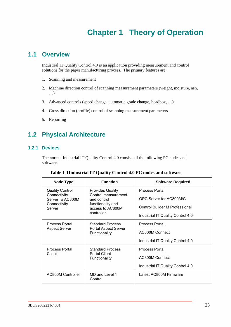
1.1 Overview Industrial IT Quality Control 4.0 is an application providing measurement and control solutions for the paper manufacturing process. The primary features are:
1. Scanning and measurement
2. Machine direction control of scanning measurement parameters (weight, moisture, ash, …)
3. Advanced controls (speed change, automatic grade change, headbox, …)
4. Cross direction (profile) control of scanning measurement parameters
5. Reporting
1.2 Physical Architecture
1.2.1 Devices
The normal Industrial IT Quality Control 4.0 consists of the following PC nodes and software.
Table 1-1Industrial IT Quality Control 4.0 PC nodes and software
Node Type Function Software Required
Quality Control Connectivity Server & AC800M Connectivity Server
Provides Quality Control measurement and control functionality and access to AC800M controller.
Process Portal
OPC Server for AC800M/C
Control Builder M Professional
Industrial IT Quality Control 4.0
Process Portal Aspect Server
Standard Process Portal Aspect Server Functionality
Process Portal
AC800M Connect
Industrial IT Quality Control 4.0
Process Portal Client
Standard Process Portal Client Functionality
Process Portal
AC800M Connect
Industrial IT Quality Control 4.0
AC800M Controller MD and Level 1 Control
Latest AC800M Firmware
3BUS208222 R4001 23

The normal Industrial IT Quality Control 4.0 will consist of one System 800xA Process Portal Aspect Server, one System 800xA Process Portal Connectivity Server (Quality Control and AC800M) and some number of System 800xA Process Portal Clients.
Figure 1-1 Example system architecture
1.3 Software Package Deployment The diagram below illustrates, at a high level, the software components that for each type of application PC node and the installation options for installing those components.
24 3BUS208222 R4001

3BUS208222 R4001 25
t architecture with example installation components Figure 1-2 Software componen
1.4 Application Architecture
1.4.1
Architecture Overview. The QCS Service is normally configured for automatic startup. It will run when the computer is started, even if
nectivity server machine. The QCS Service’s main tion component. This component is the top level
The Industrial IT Quality Control 4.0 PC based applications provide access to all of the system features except for machine direction and level 1 control, which are implemented in the AC800M Controller. The Quality Control applications are COM EXE type applications and are referred to as “components” here.
Startup and Shutdown
Refer to Figure 1-3 Quality Control Application
no user logs on to the Quality Control Confunction is to launch the ABBQCSApplicaQuality Control application. It launches and coordinates all of the other Quality Control applications.

Figure 1-3 Quality Control Application Architecture Overview
The ABBQCSApplication com tup Engine component to launch the other Quality and utility applications. The Startup Engine component starts the applications configured in the startup.xml file. This file is created and
y Control devices and application
ents.
aspect
ags that they use. See the OPC Direct IT section below.
ponent uses a Star Control application components
deployed to the ../System/config directory by the job order configuration tool. The contents of startup.xml depend upon the number and type of Qualitfeatures configured. Typically there will be a separate component for each system feature or subsystem. Refer to the Startup Engine section later in this document for more details.
Each Quality Control application component implements COM interfaces that allow the ABBQCSApplication component to coordinate their activities. The ABBQCSApplication uses these interfaces to tell the Quality Control Application components when to connect to their OPC server, when to publish their OPC tags, when to shutdown, etc.
When the ABB QCS Service is stopped, it tells the ABBQCSApplication to shutdown. TheABBQCSApplication then uses the standard COM interfaces of each Quality Control application component to tell the application components to shutdown.
Client Connectivity
Refer to Figure 1-3 Quality Control Application Architecture Overview, above. QualityControl process graphic displays do not normally use the normal OperateIT graphic elemMost Quality Control process graphic displays are based upon special process graphiccategories that contain logic for connecting to the Quality Control connectivity server. See the Aspects and Objects section later in this document for more details on these special process graphic Aspect Categories.
Many of the Quality Control process graphic Aspects contain ActiveX controls that display / modify OPC tags. These ActiveX controls use a tag lookup server to locate the OPC t
26 3BUS208222 R4001

3BUS208222 R4001 27
PC Applications
Control applications are COM EXE type applications and are referred to in this
ere
ommon broutine calls. A description of the data or command sequencing for several
tion
is solating
ent
7. Speed Input
1.4.3
vities of a group of ABBSmartMeasurement objects, one started for ent configured on that scanner. The scanner object acts as the ‘owner’ of the
1.4.2 Quality Control
The Qualitydescription as “application components” or just “components”.
While application components each tend to implement only one subsystem or feature of theentire system, they frequently have a need to communicate with each other. To this end thare two methods used to interface from application component-to-component and to the outside world. These are 1) via COM interfaces and 2) via OPC tags. The majority of communication between components is through the COM interfaces which are cmethod or sufeatures will be found in the detailed descriptions below, and they make frequent reference to these COM interface methods.
Due to the object-oriented nature of the application component implementation the interacbetween components can be quite complex with several back-and-forth transactions required to accomplish a relatively simple task. The advantage of this approach is that the softwaremodular and feature independent, allowing easy addition or removal of features and ifunctional responsibility for ease of diagnosis.
The primary Industrial IT Quality Control 4.0 application components are:
1. Scanner and Sensor
2. Color Measurem
3. Reporting Accumulation
4. Reporting
5. Reporting History
6. Roll Set
8. Grade and Shade File Handling
9. High Frequency Trending
Scanners, Sensors and Advanced Scanning
The application COM component ABBSmartPlatform.exe is responsible for all interaction with the scanner and its complement of sensors. At startup, a separate ABBSmartPlatform object is created for each scanner in the system. Once in operation, the ABBSmartPlatform object coordinates the actieach measuremmeasurements and insures that all its measurements understand the current operating conditions, such as the desired measurement mode, the position of the head package, etc. Thescanner object insures that all the sensor results are tabulated and reported in a coordinated fashion and that the measurement results align with each other in time. In general, operator communication with the scanner and measurement objects flows through the COM interfaces associated with each object.

Between the objects and the real-world physical devices reside the QC Object Server (QCOS)
s
Operation Position
.
ct head ntrol is performed by the scanner component. The ‘CurrentHeadPosition’ OPC tag current physical position of the head package to the scanner object.
Advanc
ers
ween the
ecise when both measurements are from the same location on the process. The difficulty with this is that the
ognizing and coordinating individual scanner components, ABBSmartPlatform. It makes decisions about which scanner
rs
em scanner
ism for the downstream scanners is designed in such a way that the origin (leader) of a ‘command
.
The lead scanner may change at any time by virtue of its availability (local, out-of-operation, maintenance, etc.). The change of leadership is one of the commands that is synchronized
and its OPC tag-set. The Job Order Configuration Tool is used to define the physical complement of scanners and sensors that will be available to talk to. Each scanner and measurement object subscribes to the full set of OPC tags available from that device.
The scanner keeps a list of its measurement objects that can be accessed through the scanner COM interface. Some of the measurement specific operator commands (e.g., sample check mode, compensation values, etc.) use this list to directly access specific measurement objecton a specific scanner. In this case, once they have identified the desired measurement object, they use the measurement COM interface to talk directly to that measurement object.
ing
Operationally, the scanner’s ‘command’ OPC tag is the direct connection from the scanner object to the physical scanner through the OPC interface. Once an operator command has been received by the scanner object via the COM interface, it flows through this OPC tagThe commands are general in nature, asking the scanner to assume a particular state (e.g. offsheet, scanning, etc.) and waiting for the response in the ‘mode’ OPC tag. No direpackage coreturns the ed Scanning
Advanced Scanning is an optional, licensed, value-added feature that allows multiple scannto ‘see’ the same part of the process. In a moving sheet process with several scanners distributed along the length, it is useful to insure that each discrete measurement window measures the same material, especially when there are mathematical relationships betmeasurements on different scanners. For example, a weight difference that subtracts one weight from another on two different scanners is obviously more pr
measurements occur at different times by virtue of their separation on the process.
The mechanism for accomplishing this is to insure that different scanners start their scans at the same ‘command point’ on the process which is tracked between the scanners based upon their relative separation and the line speed of the process. This feature is referred to as “Synchronized Scanning”.
A global component ABBGlobalScanner is responsible for rec
is most upstream and insures that scanner is aware that it is the ‘leader’. The leader is responsible for starting new ‘command points’ that will be followed by downstream scanne– followers. The software components of the Connectivity Server are entirely responsible for operation of this feature. When activated, this feature causes each ABBSmartPlatform component to override normal independent scanning operation of its connected Smart Platform by changing the Smart Platform’s mode from “scan-at-will” to “scan-on-command”.
Downstream follower scanners accept new ‘command points’ from the leader and track thfrom the leader to themselves by monitoring the process line speed. Each individual is assigned a relative position on the process at startup which is used to decide when the ‘command point’ has reached them and should be obeyed. The synchronization mechan
point’ is irrelevant and simply has to match the position of the specific downstream scanner
28 3BUS208222 R4001

3BUS208222 R4001 29
lost
Change
termines when a ‘command point’ will reach a downstream scanner, a s
ow a osition to
based on the current line speed. In ords, if the scanner can successfully reach the other side of the process sheet and
start-scan command will arrive, then scanning is
’ may flow by the downstream scanner before it is in a position to accept them i.e., the scanner is still moving
ss
Scanne
start scanning when a ‘command point’ becomes available. For example, a substantially slower scan time may insure that a
he l
ownstream scanner. The mechanism described ine speed) will insure that a scan will eventually occur, however,
ey are discarded and a catch-up is required.
y
duration of lay its scan until it is sure that
all scanners will have sufficient time to ‘catch’ its first start-scan ‘command point’ after a
ed as either
ween these two is that tracking is considered only for the global type, not for the individual. An individual standardize request, whether via button or timer causes that scanner to become ‘unavailable for synchronization’.
between scanners so that intervening commands (and potentially measurements) are not to downstream scanners.
Missing Scans
By virtue of the fact that downstream scanners are dependent on synchronization for their start-scan command, it is possible for downstream scanners to miss scans. In these cases the next best possibility for measurement is to wait for the next ‘command point’ on this side ofthe process sheet to arrive; in other words to quit scanning until a complete bi-directional scanis tracked to this scanner. Some of the scenarios for missed scans and the mechanisms implemented to reduce their occurance are: of line speed
Since the line speed dechange in line speed will obviously have an impact. In general a decrease in line speed ibenign in the sense that the start-scan command will eventually reach the scanner, it’s just delayed for a while. There is a ‘delayed scan’ feature built into the tracking that will alldownstream scanner to proceed with a scan (and measurement) only if it can be in preceive the next ‘command point’ in the tracking queueother wreturn to the current position before the nextallowed to proceed. There are special considerations to handle or discard mis-aligned measurements in this case – see Inter-scanner Measurement, below.
An increase in scan speed is a potential problem in that ‘command points
for the previous scan. This is physically an unsolvable dilemma that is somewhat alleviated by the fact that due to the higher line speed subsequent scan points on this side of the procesheet will arrive sooner than originally scheduled. Start-scan ‘command points’ that are missed are discarded, however some commands are honored regardless – for example, achange of tracking leadership or a standardize request will be honored immediately. r activities
Activities of downstream scanners may affect their ability to
downstream scanner misses the ‘command point’ scan request and subsequently loses topportunity to measure for a complete forward and reverse scan. This sort of scenario wilresult in periodic ‘skipping’ of scans on a dabove (Change of lsubsequent scans will fall further behind until thThis could be severe enough that only alternate scans are honored.
A second activity that impacts’ scanning is standardize duration. A downstream scanner mahave a substantially longer standardize duration than the lead scanner, since this is sensor dependent. A self-tuning feature has been implemented that considers the relative standardizes between scanners and causes the lead scanner to de
global standardize. In effect the lead scanner takes on the standardize duration of the longest downstream scanner duration. This is controlled by the ABBGlobalScanner component. An initial value for this duration is provided in a coldstart value.
Some additional comments about standardize – requests for standardize are classifiindividual or global, depending upon whether the request is issued via a specific scanner’s interface or the global scanner’s interface. The difference bet
The effect for downstream scanners is to step out of synchronization temporarily, bas soon as standardize is complete – note that when they return they may be totally out of alignment with respect to the leader and may have to wait a full bi-directional scan to get properly aligned. The effect for the lead scanner is similar, except that leadership is reassigned to the next most downstream sc
ut to return
anner. In this case when returning from standardize it will reclaim leadership, which may result in downstream scanners waiting for scans.
o
Operato
e operator to disable a scanner or to cause it to operate in a different mode ing
r nt.
l resume synchronized scanning. If they are the most upstream, they will be assigned as the lead scanner.
Indepen
Measur
om this 5-second data. The profiles and their edge-of-sheet.
ad
nd processed he
shed
scan
easurements that calculate their result by reference to some other measurement are known
tional.
A feature to force measurement quickly after a standardize causes downstream scanners tperform an immediate scan after returning on-sheet after standardize regardless of synchronization. The concept allows quick measurement and simply defers the wait for ‘command point’ to the far sheet edge. r intervention
Requests from thwill impact synchronization. As mentioned above, standardize requests may affect scannof both the lead scanner and downstream followers. Also, any operator intervention to take the scanner out of computer control will obviously affect synchronization. If the lead scanneis put out-of-service, a new lead scanner will be selected by ABBGlobalScanner componeWhen scanners are returned to operation, they wil
dent Operation Mode
A independent mode is provided via operator request that completely disassociates the scanner from the ABBGlobalScanner component and all synchronization. Once placed in independent mode, the scanner will operate totally independently from other scanners, including scanning. When in independent mode, the scanner will not participate in synchronization and cannot become the lead scanner. ement
All measurement processing is performed exclusively on 5-second data by the scanner component and its measurement objects. The measurement objects and their subordinate objects are responsible for building profiles frrelated statistical data are published as OPC tags at every
The scanner monitors the OPC tag ‘TBM5SecDataReadyTrigger’. This tag is sent from the Smart Platform to indicate that all measurements for this 5-second time slice (TBM) have been completed. When this trigger is seen, the data box and head position arrays are refrom the Smart Platform. The scanner component uses the collection of measurements configured on this scanner to iteratively ask all measurement arrays to be read aand on-going profile construction to be performed. When an edge-of-sheet is detected in tscanner’s data box array the profile processing is completed, the profile result is publiand the profile is initialized in preparation for the next scan.
The scanner expects a returned result from each measurement as a data object of class CABBDataObject which contains the processed TBM array, the TBM average, theaverage, and a status among other things.
Calculated Measurement
Mas ‘calculated measurements’. A calculated measurement is an object instance of a (new) CABBCalcMeas class which supports the same COM interface (IABBMeasurementIF) as ‘real’ measurements. The concept of the calculated measurement is tightly coupled to the entire ABBSmartPlatform component design and impacts the functionality of all measurement features and as such is implicit and not op
30 3BUS208222 R4001
3BUS208222 R4001 31
. The relationship between the calculated measurement and its contributors mined by an algorithm which is defined in the “std_algorithms.xml” file and is also
local (this scanner) or upstream (different scanner)
le as
bject is returned result to be
consistent (a CABBDataObject instance).
eives its processing request from the scanner object it asks he ments
they are local measurements (this scanner) or whether they hed
Measur
ctions. entire
ABBSmartPl measurement features and
The implementation of tracking rests on the two object classes CABBVirtualScanner and CABBVirtualMeasurement. [Software detail: These classes act as agents for a calculated measurement and represent an upstream scanner or upstream measurement respectively to the local scanner or ‘owner-scanner’. When a calculated measurement object is first started, it’s contributors list is examined for residence of each measurement. A new virtual scanner object is created for every unique scanner identified from this list. This virtual scanner retains COM interface ties to its target (upstream) scanner which will be used during subsequent measurement processing. A new virtual measurement object is created for each measurement that is identified from the contributors list that resides on that scanner and likewise retains COM interface ties to its target (upstream) measurement. The virtual scanner keeps a collection of these virtual measurements in a similar fashion to how the scanner component keeps its collection of ‘real’ measurements.]
The virtual scanner object (CABBVirtualScanner) is primarily responsible for recognizing when a tracked measurement has reached the owner-scanner and for distributing the tracked data to the virtual measurements that it contains. An incidental (but very important)
to track scanning commands for the Synchronized Scanning feature.
ts
in the calculated measurement’s algorithm as described above.
Calculated measurements are made aware of their measurement dependencies at startup via a ‘contributors’ listis deterestablished at startup. In general, anymeasurement is fair-game as a contributing measurement; even other contributing measurements may contribute. Conversely, downstream measurements are inaccessibcontributors (although their grade information is available).
Processing of calculated measurements follows the same initial sequence as ‘real’ measurements. After seeing the scanner’s data ready trigger, the scanner object asks each calculated measurement to read and process its measurement arrays. The scanner ounaware of the different measurement types and only expects the
When a calculated measurement receach of its contributing measurements for their TBM array and forwards this data to talgorithm processor. The accessing of TBM array data from the contributing measurediffers depending upon whetherreside on a different (upstream) scanner (see Measurement Tracking, below). The finisTBM array, its average and status are all returned in the CABBDataObject. ement Tracking
Measurement tracking is the proprietary mechanism that allows the measurements from multiple scanners to be properly aligned in both the machine and cross-machine direMeasurement tracking, or tracking as it is referred to herein, is tightly coupled to the
atform component design and impacts the functionality of allas such is implicit and not optional.
responsibility is
The virtual measurement object (CABBVirtualMeasurement) has two primary responsibilities. First is to populate a “living” profile with tracked measurement from itarget upstream measurement. When notified by the virtual scanner that new tracked measurement is available, the new data is overlaid onto a permanent profile array. Second,when requested, examine this “living” profile for a prescribed set of boxes and create an artificial TBM array for this contributing measurement. This is the TBM array that will eventually be used

Scanne
d scanner physically exists and has been configured in the Job Order Configuration Tool prior to startup. If this is not true then system startup will not finish properly and will generate numerous errors.
tup.xml file (‘At_reel’) allows configuration of whether this scanner is
Measur
Each scanner in the startup.xml file contains a ‘list’ bracket entry that encloses all of its own ry is found in the scanner’s list for each e configured measurement physically exists and
has been configured in the QC Object Server’s Job Order Configuration Tool prior to startup. e then system startup will not finish properly and will generate numerous
spect to calculated measurements, the order that measurements appear in the
1.4.4
PMxMITHSIProductionSummary.xml where PMx refers to the machine instance.
igure 1-xx Production Summary Aspect Overview
Configuration and Startup r
A separate configuration entry is found in the startup.xml file for each scanner. An assumption is made that the configure
An argument in the starthe reel scanner. ement
measurements. A separate configuration entmeasurement. An assumption is made that th
If this is not truerrors. With relist is important. Any measurements on that scanner that are used by a calculated measurement should appear before the calculated measurement.
Production Accumulation
The application COM component ABBMIS.exe is responsible for accumulation and publishing of production data.
The Production Summary aspect (part of the IndustrialIT Quality Control object type structure) contains two Generic Control (GC) grid displays. Fig 1-xx shows a typical aspect configuration in which three work shifts are configured. The GC grid can be modified via editing the associated XML file. The XML file is located within the following directory structure: Quality Control Solutions\Measure IT\HSI. The XML file is called
F
32 3BUS208222 R4001
3BUS208222 R4001 33
,
he QCS LAN network, as remote client operator stations require access. The database may be accessed by remote customer nodes as well for detailed
n SQL
le new
change, standardize, end
1.5 Networking formation for information on the network
1.6
1.6.1 Overview
he Job Order Configuration project will produce a toolset that project engineers will use to IT
configuration via a graphical user interface. When the project engineer has entered all uration information he will request the tool to build the job order dependent
and create sub-folders for each application computer node. The configuration tool will store e job order dependent files for each application node in the sub-folder for that node. When
the project engineer has loaded the application software on the application nodes he will and request the configuration tool to deploy
. The configuration tool will copy those files to the appropriate directories on the application nodes. The project engineer will then
wnload the AC800M controller and build the application grade codes using other tools
1.6.2 Database
crosoft Access database containing the tables, s and code that represent the configuration information for Quality
ests creation and deployment of the job order configured output files via Access forms.
1.4.5 Reporting
All MeasureIT reporting is based upon historical data stored on a SQL database named “ABBMeasureHistory”. A SQL server (MSDE) is installed when MeasureIT server is installed. This SQL server is configured to start up automatically when the machine is startedso it is always available. The “ABBMeasureHistory” database is typically left completely open to access by other nodes on t
QCS information.
All report data originates with accumulations that are published on the OPC Server. On aevent basis these OPC accumulations are gathered, stored on the “ABBMeasureHistory”database and reset for subsequent accumulation. In general each event generates a singdatabase record. Some of the events that cause report data storage are: reel turnup, grade
of day, etc.
Refer to the Administrator’s Guide for inconfiguration for the Industrial IT Quality Control 4.0.
Job Order Configuration
Tconfigure Industrial Quality Control 3.0. The project engineer will enter the job order
configconfiguration files. The job order tool will build a project folder on the project engineer’s PC
th
connect his computer to the application network the job order dependent files to the application nodes
dosupplied by the controller platform group and by the Infrastructure project.
The job order configuration database is a Mirelationships, queries, formControl system job orders. The user enters the configuration information and requ

1.6.3
ase is converted into an XML document when the user requests the tool to build the job. The configuration XML file
e s us configuration tuator OPC tags, grade code, AC800M
controller programs and I/O, ABB Object and Aspects). XSLT (Extensible Style Sheet anguage Transforms) and custom code are used to create the configuration dependent files.
XSLT Transforms
guration tool uses XSLT (with some embedded script) to create the job order configuration dependent XML files. The main XSLT file (Main.xslt) creates folders for
ration files for that node. The main XSLT file outputs an HTML log file containing the actions
Main.xslt
Main.xslt is the driver for generating all configured files. It uses a combination of XSL
ocessing performed by Main.xslt.
Configuration File Generation
Overview
The job order configuration entered into the Microsoft Access datab
contains th sy tem configuration information used to build the variodependent files (Startup engine, scanner and ac
L
The job order confi
each application node and invokes the XSLT transforms required to create the configu
performed and error information.
templates and embedded script to create the configuration files for the job order. The following flowchart illustrates the pr
34 3BUS208222 R4001

3BUS208222 R4001 35
Figure 1-4 Main.xslt flow chart
jotemp.xml jotemp1.xmljoconfigex.xslt
jotemp1.xml joconfig.xmljoconfigex.xslt
joconfig.xml deploy.batdeploy.xslt
Create PC Node Directory underprojects/joborder folder
joconfig.xml DirectStruct.xmlDirectStruct.xslt
For Each Application PC Node
Process DirectStruct.xml(create folders, copy files, perform XSL
DirectStruct.xml)
transforms, invoke executables basedupon XML commands in
The majority of the work ists ofine
ed
deployed.
done here. The contenDirectStruct.xslt determwhat outputs are creatand where they are
All NodesCompleted?
No
Yes
Done
Pre-processing phase 1.Add attributes to existingelements to facilitate laterprocessing.
Pre-processing phase 2.ts and
other processing dependente
Add grouping elemen
upon phase 1 to facilitatlater processing.
Generate file deployment
application PC node).
batch file (contains oneXcopy command per
Loop over each applicationnode creating a mirror ofthe application nodesdirectory structure and
structure. This will allow usto copy the structure to theapplication node with thedeploy .bat file.
DirectStruct.xslt
DirectStruct.xslt contains an XML representation of the application directory structure for the
e flowchart for Main.xslt. A description of the syntax of the XML elements in DirectStruct.xslt follows:
generating the configuredfiles for each folder in the
application PC nodes. Various XML elements cause Main.xslt to create folders, copy files, perform XSLT transforms and launch executable programs as described in th
**************************************************************************************
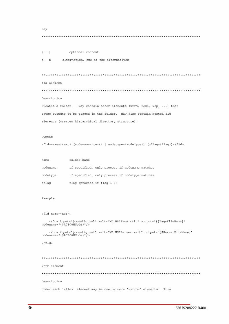
Key:
**************************************************************************************
[...] optional content
a | b alternation, one of the alternatives
***************** ******************************************************** *************
fld element
********** ** ********************************************* ** ***************************
Description
Creates a ol r. May contain other eleme f de nts (xfrm, rexe, xcp, ...) that
cause outputs to be placed in the folder. May also contain nested fld
elements (creates hierarchical directory structure).
Syntax
<fld>name="text" [nodename="text" | nodetype="NodeType"] [cflag="flag"]</fld>
name folder name
nodename if specified, only process if nodename matches
nodetype if specified, only process if nodetype matches
cflag flag (process if flag > 0)
Example
<fld name="HSI">
<xfrm input="joconfig.xml" xslt="MD_HSITags.xslt" output="{$TagsFileName}" nodename="{$AC800MNode}"/>
<xfrm input="joconfig.xml" xslt="MD_HSIServer.xslt" output="{$ServerFileName}" nodename="{$AC800MNode}"/>
</fld>
**************************************************************************************
xfrm element
**************************************************************************************
Description
Under each '<fld>' element may be one or more '<xfrm>' elements. This
36 3BUS208222 R4001
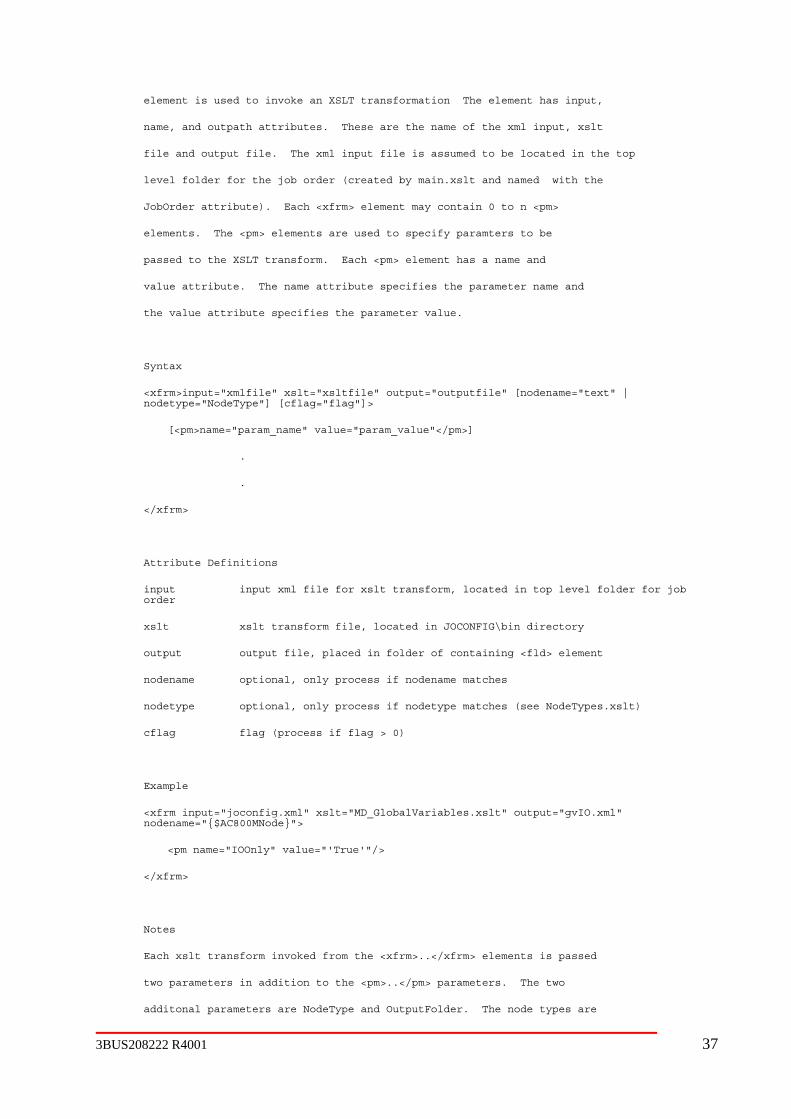
3BUS208222 R4001 37
element i us to invoke an XSLT transformation The eles ed ment has input,
name, and ut th attributes. These are the name of the xmo pa l input, xslt
file and output file. The xml input file is assumed to be located in the top
level fol r r the job order (created by de fo main.xslt and named with the
JobOrder attribute). Each <xfrm> element may contain 0 to n <pm>
elements. The <pm> elements are used to specify paramters to be
passed to the XSLT transform. Each <pm> element has a name and
value attribute. The name attribute specifies the parameter name and
the value attribute specifies the parameter value.
Syntax
<xfrm>input="xmlfile" xslt="xsltfile" output="outputfile" [nodename="text" | nodetype="NodeType"] [cflag="flag"]>
[<pm>name="param_name" value="param_value"</pm>]
.
.
</xfrm>
Attribute Definitions
input input xml file for xslt transform, located in top level folder for job order
xslt xslt transform file, located in JOCONFIG\bin directory
output output file, placed in folder of containing <fld> element
nodename optional, only process if nodename matches
nodetype optional, only process if nodetype matches (see NodeTypes.xslt)
cflag flag (process if flag > 0)
Example
<xfrm input="joconfig.xml" xslt="MD_GlobalVariables.xslt" output="gvIO.xml" nodename="{$AC800MNode}">
<pm name="IOOnly" value="'True'"/>
</xfrm>
Notes
Each xslt transform invoked from the <xfrm>..</xfrm> elements is passed
two parameters in addition to the <pm>..</pm> parameters. The two
additonal parameters are NodeType and OutputFolder. The node types are
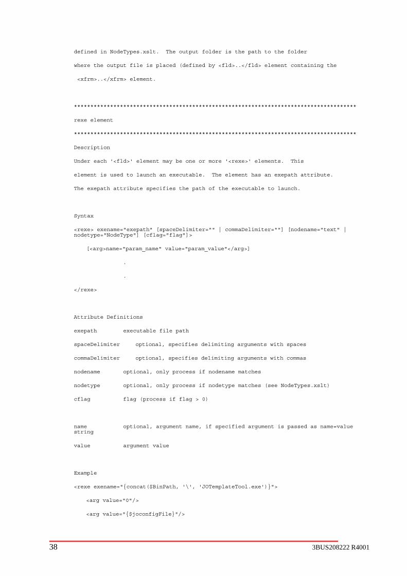
defined in NodeTypes.xslt. The output folder is the path to the folder
where the output file is placed (defined by <fld>..</fld> element containing the
<xfrm>..</xfrm> element.
**************************************************************************************
rexe element
**************************************************************************************
Description
Under each '<fld>' element may be one or more '<rexe>' elements. This
element is used to launch an executable. The element has an exepath attribute.
The exepath attribute specifies the path of the executable to launch.
Syntax
<rexe> exename="exepath" [spaceDelimiter="" | commaDelimiter=""] [nodename="text" | nodetype="NodeType"] [cflag="flag"]>
[<arg>name="param_name" value="param_value"</arg>]
.
.
</rexe>
Attribute Definitions
exepath executable file path
spaceDelimiter optional, specifies delimiting arguments with spaces
commaDelimiter optional, specifies delimiting arguments with commas
nodename optional, only process if nodename matches
nodetype optional, only process if nodetype matches (see NodeTypes.xslt)
cflag flag (process if flag > 0)
name optional, argument name, if specified argument is passed as name=value string
value argument value
Example
<rexe exename="{concat($BinPath, '\', 'JOTemplateTool.exe')}">
<arg value="0"/>
<arg value="{$joconfigFile}"/>
38 3BUS208222 R4001

3BUS208222 R4001 39
<arg value="transform-cd-opc.xml"/>
<arg value="{$XSLPath}"/>
<arg path=""/>
</rexe>
**************************************************************************************
xcp element
**************************************************************************************
Description
Under each '<fld>' element may be one or more '<xcp>' elements. This
element is used to copy a file into the f
older defined by the <fld> element.
Syntax
<xcp srcpath="path" [nodename="text" | no d
detype="No eType"] [cflag="flag"]/>
Attribute Definitions
srcpath file path of file o py to this fold t co er
nodename optional, only process if nodename matches
nodetype optional, only process if nodetype matches (see NodeTypes.xslt)
cflag flag (proce
ss if flag > 0)
Example
<xcp srcpath="{concat($SchemaPath, \ Ct
1.6.4 Configuration F t
Overview
The user can connect the configurati t t request the tool to deploy the configuration files to the application nodes. The tool invokes a batch file (deploy.bat) containing XCopy mands to copy the configuration files to the appropriate directories on the application nodes. for the application nodes creates a netwo re “Quality Control Solutions” for the installation directory
The location of the batch file
' ', 'OP ransporter.dtd')}"/>
ile Deploymen
on ool PC o the Quality Control System network and
com This requires that the installation package
rk sha.
deploy.bat for the Job Order JOINTEGRATE is shown as:

Figure 1-5 Batch file location for Job Order configuration
Graphi Use
The “Deploy Jo
Figure 1-6 After configuring system chose Deploy Job button
cal r Interface
b” button shown from the following picture is used to deploy the job order.
Directory structure at configuration Tool PC
Figure 1-7 Directory structure on configuration tool PC
40 3BUS208222 R4001

3BUS208222 R4001 41
<Drive>
• • DB • IOWor• Projects folder for job orders
JOINTEGRATE a job order configured •
s
Dictionary scanner and actuator OPC Tag files Control IT root directory for control project
data files for cross direction control project o config static data files that define the configuration o data data files that may be routinely modified
OPC OPCTransporter & other OPC tag mapping
s
o config static data files that define the configuration
:\Program Files\ABB Industrial IT\Quality Control Solutions\Engineer IT\JOCONFIG\
bin all binaries, application OCXs, and XSLT files configured database file and help file kSheets IO templates and configuration file
• ABB-QC1 a node configured from the tool
Quality Control Solutions shared drive for objects and aspects icon Communicate IT root directory for QC OPC server
o
CD control
o files
o HSI TagLookup and other client display assist files
o IOWorkSheets IO templates and configuration file MD control data files for machine direction control project

o data data files that may be routinely modified OPC OPCTransporter & other OPC tag mapping
o HSI TagLookup and other client display assist files
config static data files that define the configuration
modified OPC OPCTransporter & other OPC tag
mapping files
assist files Custom data files for custom projects Grade Grade code files
ty Control data files for the measurement project • config static data files that define the configuration • data data files that may be routinely modified
ing les
• HSI TagLookup and other client display assist files
Profile IT root directory for the profiler project o CD actuator data files for CD actuator project
• config static data files that define the configuration • data data files that may be routinely modified
okup and other client display assist files
System data files shared by multiple projects
n Directory Structure
Control Solutions network share in the target
& aspects • help system on-line help files
o files
o Signal Processing data files for measurement signal processing
data data files that may be routinely
HSI TagLookup and other client display
Shade Shad code files Measure IT root directory for the measurement project
o Quali
• OPC OPCTransporter & other OPC tag mappfi
• OPC OPCTransporter & other OPC tag mappingfiles
• HSI TagLo
config static data files that define the configuration data data files that may be routinely modified
Destinatio
\\Target Node\Quality
• bin all binaries and application OCXs • backup backup area for files replaced during
installation • import AFW files in sub-folders containing objects
42 3BUS208222 R4001

3BUS208222 R4001 43
user documentation in .PDF format • icons objects and aspects icons
static data files that define the configuration o data data files that may be routinely modified
• Measure IT o Quality Control data files for the measurement project
config static data files that define the configuration data data files that may be routinely modified OPC OPCTransporter & other OPC tag mapping
files HSI TagLookup and other client display assist
files • Control IT
o MD Control data files for machine direction control project
config static data files that define the configuration data data files that may be routinely modified OPC OPCTransporter & other OPC tag mapping
files HSI TagLookup and other client display assist
files o IOWorkSheets IO templates and configuration files o CD Control data files for cross direction control project
config static data files that define the configuration data data files that may be routinely modified OPC OPCTransporter & other OPC tag mapping
files HSI TagLookup and other client display assist
files o Signal Processing data files for measurement signal processing
config static data files that define the configuration data data files that may be routinely modified OPC OPCTransporter & other OPC tag mapping
files HSI TagLookup and other client display assist
files o Profile IT
CD actuator data files for CD actuator project • config static data files that define the configuration • data data files that may be routinely modified • OPC OPCTransporter & other OPC tag mapping
files • HSI TagLookup and other client display assist
files
• doc
• grade grade code configuration • shade shade code configuration • System data files shared by multiple projects
o config

• MeasSi signal processing o config static data files that define the configuration o data data files that may be routinely modified o OPC OPCTransporter & other OPC tag mapping
files o HSI TagLookup and other client display assist
files • Custom data files for custom projects
o config static data files that define the configuration o data data files that may be routinely modified o OPC OPCTransporter & other OPC tag mapping
files o HSI TagLookup and other client display assist
files • Communicate IT root directory for QC OPC server
o Dictionary scanner and actuator OPC tag files • Engineer IT root directory for job order configuration • Reports directory for roll set analysis
o Production production reports o Sensors sensor reports
Actions
When a job order is deployed, each folder under <drive>:\Program Files\ABB Industrial IT\Quality Control Solutions\Engineer IT\JOCONFIG\Projects\JOINTEGRATE will be copied from configuration tool PC to configured application nodes, if there is any file(s) existing underneath as leaf(s).
1.6.5 Troubleshooting
General
If the Job Order configuration tool crashes or exhibits other unusual behavior you may have a complete (not just run-time) version of MS Access installed. Verify that the MS Access Visual Basic Editor is set to break on unhandled errors, not break on all errors. To check the setting, open an Access Database and open the Visual Basic Editor. Use the Tools-Options menu to open the options dialog. The error handling section is under the General tab.
Configuration File Deployment
If the configuration files are not copied to the application PC, check:
PC Name
Verify that the name of the Application PC matches the name specified in the configuration.
etwork Connection
Verify the network connection to the application PC by using the ping command from a DOS command window.
gnalProcessing data files for measurement
N
44 3BUS208222 R4001

3BUS208222 R4001 45
n
a shared folder named Quality Control Solutions. The
Access Rights
ite permission to the application PC application folder under the Quality Control Solutions network share.
1.7
1.7.1 Overview
The Quconnectivityof connectiv
1.7.2 Role o
OPC is usedcoupling Qu Quality Control OPC server is uploaded into the Process Portal Control Structure. This allows access to the Quality Control OPC tags by
1.7.3
1.7.4 Publishing
PC server supports a proprietary means of publishing data into the ontrol applications such as scanner, measurement, control and report
Control OPC server using this proprietary interface. are available in the OPC server are a combination of device tags (Scanning
Platform and Actuator) and published tags.
Quality Control Installation
Verify that the Industrial IT Quality Control 4.0 Connectivity was installed on the applicatioPC.
Network Share
Use Windows Explorer on the configuration PC and browse to the application PC under My Network Places. Verify that there isinstall tool creates the network share.
Verify that you have wr
OPC Server
ality Control OPC server is central to Industrial IT Quality Control 4.0. It provides to the Scanning Platform and Smart Actuator devices and is the primary means ity between Quality Control applications.
f OPC
for connectivity to Smart Platforms and Smart Actuators and is also used to for ality Control applications. The
Process Portal services and applications, including the Property Transfer Service and Process Graphics.
Data Dictionary
For AC800M solutions the Data Dictionary is now obsolete. The Job Order Configuration Tool is now used to configure the Quality Control OPC server. For Industrial IT Quality Control 4.0 its use is limited to Smart Platforms and Actuators. The AC800M Controller has its own separate OPC server.
The Quality Control OOPC server. Quality Capplications publish data into the QualityThe tags that

Figure 1-8 - Quality Control Object Server Overview
Object ServerASI Device
ASI Device
ASI Device
OPC Client
ASI CommEngine
TCP communication linkbetween devices and OPCserver using ASI protrocol
TCP Communication linkbetween OPC Server and
OPC Client
OPCPublishEngine
Publishing Client
Run TimeTag Data
Base
Named Pipe Protocol usedto communicate betweenpublishing client and OPC
Server
OverviewABB Qualtiy Control Object Server
Publishing client defines itsown tags and data and adds
the tags to the runtimedatabase dynamically. ThePublishing client is normally
on the same node as theQCOS in order to avoid
additional network overheadused by named pipe
protocol.
November 21, 2003
Bob TournouxQCS Systems
DataDict.MDB
Data DictionaryAdmin
MasterDataDictionary
Data Dictionary Admin toolconfigures a unique
database which specifies thetags on each ASI device that
will be used. The ASIdevices are configured whenthe QCOS starts up and at
this time the ASI device tagsare added to the runtime
database.
OPC 2.05aServer
XML Configuration File
The XML Tag configurationfile contains ASI Device andtag info. The QCOS will use
this info to configure ASIdevices and add the tags tothe runtime database when
QCOS starts up.
46 3BUS208222 R4001
3BUS208222 R4001 47
1.8 OPC TransThe OPC Transporter is used to transport data between different branches in the same OPC server or between different OPC servers. The OPC Transporter is used to connect Quality Control applications to other Quality Control applications and to foreign applications and devices. As an example, measurement data is transferred to the AC800M controller by an OPC Transporter configured to transport the measurement data from the Quality Control OPC server to the AC800M OPC server.
Refer to Appendix A for a complete description of the OPC Transporter.
1.9 OPC Direct IT
1.9.1 Overview
OPC Direct IT is a client side component, used by clients to access data in an OPC server. OPC Direct IT provides the following features not available using the standard OPC server interface.
10. OPC Direct IT monitors the connection to an OPC server, and notifies its clients when the OPC server is available (UP) or unavailable (DOWN), without blocking client applications. Reconnections to OPC server are made by OPC Direct IT, and not the client applications.
11. OPC Direct IT can keep data groups, defined by client applications, alive in memory even after the client applications terminate. The next time a client application runs, its data is available immediately (no waiting on the OPC server connection path to be rebuilt).
Clients using OPC Direct IT receive data exactly the same way as if they connected directly to the OPC server themselves.
OPC Direct IT is designed to limit the number of threads produced by OPC servers. This is done by creating only one OPC Group object for each refresh rate required by OPC Direct IT clients. For example, if 7 different OPC Direct IT clients subscribe to data in an OPC server at refresh rate of 5 seconds, then OPC Direct IT places all subscriptions into one OPC Group object (with refresh rate of 5 sec). If 3 clients want 1 sec data and 4 want 5 sec data from an OPC server, then OPC Direct IT creates 2 OPC Group objects. A 1 second refresh object and a 5 sec refresh object. See “OPC Direct IT Viewer” for graphical representation of the internal structure of OPC Direct IT.
1.10 Tag Lookup
1.10.1 Overview
There are three kind methods to communicate between the HSI display and OPC server: The first one is using interface and component object, the second is using OPC DirectIT, an the third is using TagLookup. The first method will create OPC group on the server PC, and all clients will share those OPC groups. The second method will create OPC group on the client side. Both those two methods require embedded application knowledge and specific data tags
porter

inside HSI controls or c oved, or added, or moved to the different location in be changed and recompiled. For the flexible maintenance and future reusable of ActiveX control, the TagLookup service along with enhanced OPC Direct IT method is used.
The TagLookUp Service is a XML based application. It includes a server side component, interface, and implementation on the client side. On the server side, it is activated by the Startup Engine. It reads XML files that contain the tags and server information and passes that information to the client. Once an ActiveX control on the client side acquires the data tag identification, OPC Direct IT is used to update and get updated of the data tag information. Those ActiveX controls that designed with TagLookup interface are general purpose controls, the prior embedded application knowledge is not required.
The following diagram illustrates, at a high level, how TagLookUp works on server and client side.
omponent. If a tag been renamed, or rem OPC server, the HSI program code need
48 3BUS208222 R4001

Figure 1-9 Tag Lookup flowchart on server
QCS Service
QCS Applications
QCSConnector
OPC Server
TagsLookUpService
(Using ABBFile Server)
Other component need to bestarted
(It’s not limited on same PC)
Tags Information XML file 1 Server Information XML file
XML file
(Depend on the content of the XML file, it willstart OPC Server, TagsLookUp Service, … )
System Startup
Tags Information XML file n
...
1
2
3
4
4
5
4
5 5
3BUS208222 R4001 49

Figure 1-10 Tag Lookup on client
Call QCSConnect
Connected
Call TagLookup.getControlInfo to get a group of tags andattributes information
Based on tags and attributes information from TagLookup,or persistence file using OPCDirectIT method to create
OPC groups.
DataChange event in OPC group
Is RevID
Clean up
Update display /ActiveX control
Yes
No
Call TagLookup.getControlID
Using persistence file?
Equal to user inputtedcontrol ID?
Connect to QCS server node
Yes
No
Yes
Clean up / Exit
No
No
Yes
1.10.2 Usage
All MD f MIT asurement Overview and Color Measurement are using the TagLookup
also.
1.10.3 Configuratio
The startup XML file, tags and server information XML files are currently generated from the r Configuration Tool.
Startup.xml
TagLookUp service will be activated by the Startup Engine; there is a startup.xml file that will specify the components that are required to be started. For a complete description, see
, CD tuning and operator displays are using the TagLookup. Some odisplay: Me
n
Job Orde
50 3BUS208222 R4001

3BUS208222 R4001 51
n. A brief description is provided here to describe how to setup the TagLookup in startup.xml.
<fileserver type="XML"> ABBFileServer.CXMLServer </fileserver>
PM1">
s">
<param Control
<param argID="XMLPath1">\\abbbuildtest01\Paper Quality Control\Control IT\MD Control\HSI
<param Process
<param argID="XMLPath3">\\abbbuildtest01\Paper Quality Control\Profile IT\CD Actuator\HSI</param>
<param argID="XMLPath4">\\abbbuildtest01\Paper Quality Control\Measure IT\Quality Control\HSI
<param argID="XMLPath5">\\abbbuildtest01\Paper Quality Control\Custom\HSI</param>
</compo
</applicati
<filese
Description
<OPCser
Description
<collection> TagsLookUpControls </collection>
gsLookUpControls” is a collection name. It is passed from the used by all ActiveX controls.
<component ID="TagLookup" class="TagsLookUpControls">
<progID>ABBTagsLookUp.CABBTagsLookUpService</progID>
Startup Engine sectio
Example:
<OPCserver type="QCSOS">AccuRay.Object.Server.1 </OPCserver>
<application name="
<collection> TagsLookUpControls </collection>
<component ID="TagLookup" class="TagsLookUpControl
<progID>ABBTagsLookUp.CABBTagsLookUpService</progID>
argID="XMLPath">\\abbbuildtest01\Paper Quality Control\Control IT\CD \HSI</param>
</param>
argID="XMLPath2">\\abbbuildtest01\Paper Quality Control\Control IT\Signal ing\HSI</param>
</param>
nent>
on>
rver type="XML"> ABBFileServer.CXMLServer </fileserver>
: ABBFileServer is used by TagLookup to read XML file.
ver type="QCSOS">AccuRay.Object.Server.1 </OPCserver>
: The TagLookup may need to publish tags to the AccuRay Object Server.
Description: The “TaABBQCSApplication, and will be
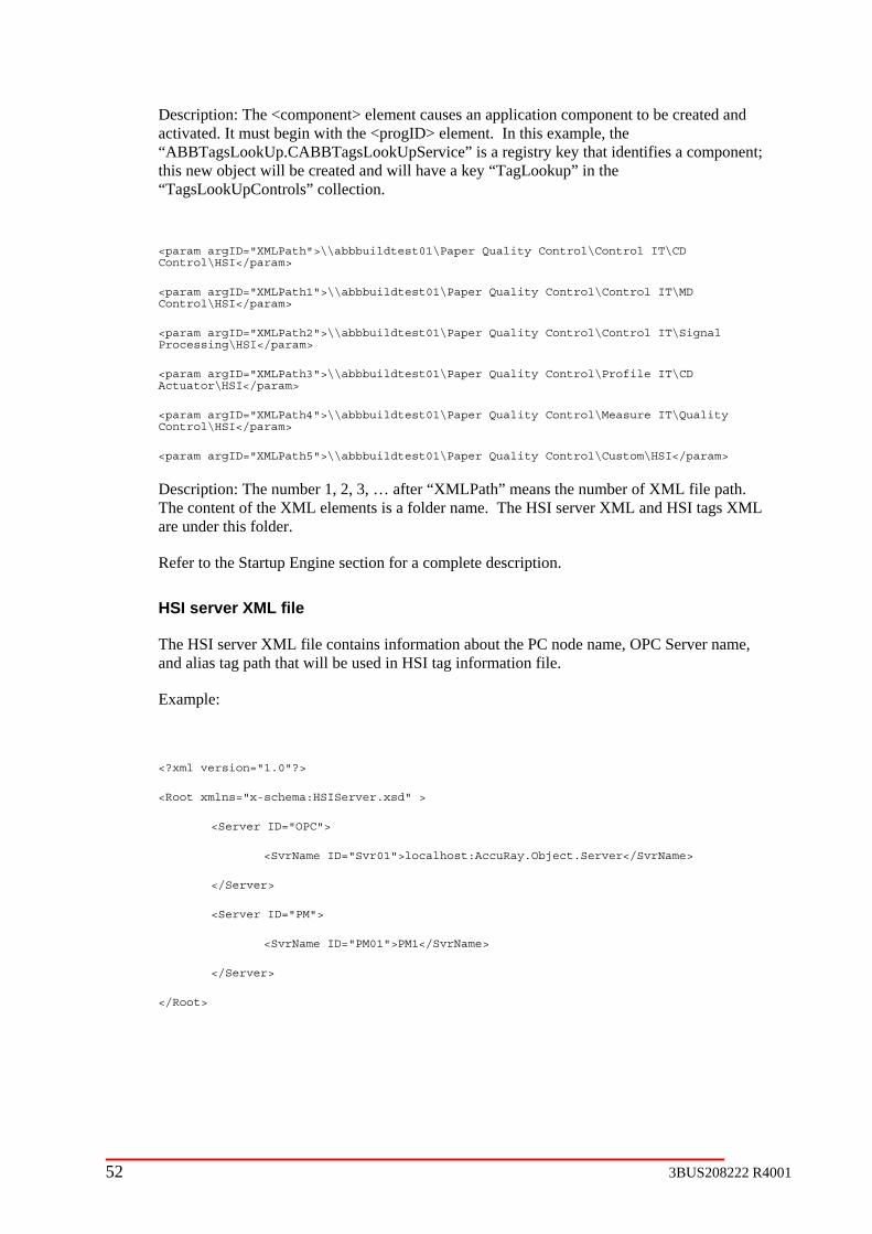
Description nt causes an application component to be created and activated. It <progID> element. In this example, the “ABBTagsLookUp.CABBTagsLookUpService” is a registry key that identifies a component; this new object will “TagsLookUpControls” collection.
<param argID="XMLPath">\\abbbuildtest01\Paper Quality Control\Control IT\CD Control\HSI
<param argID="XMLPath1">\\abbbuildtest01\Paper Quality Control\Control IT\MD Control\HSI</param>
<param argID="XMLPath2">\\abbbuildtest01\Paper Quality Control\Control IT\Signal Processing\HSI</par
<param argID="XMLPath3">\\abbbuildtest01\Paper Quality Control\Profile IT\CD Actuator\HSI</param>
<param argID="XMLPath4">\\abbbuildtest01\Paper Quality Control\Measure IT\Quality /param>
om\HSI</param>
Description: The number 1, 2, 3, … after “XMLPath” means the number of XML file path. elements is a folder name. The HSI server XML and HSI tags XML
C node name, OPC Server name,
<?xml version="1.0"?>
<Root xmlns="x-schema:HSIServer.xsd" >
<Server
Name ID="Svr01">localhost:AccuRay.Object.Server</SvrName>
rver>
<Ser
<SvrName ID="PM01">PM1</SvrName>
</Server>
</Root>
: The <component> eleme must begin with the
be created and will have a key “TagLookup” in the
</param>
am>
Control\HSI<
<param argID="XMLPath5">\\abbbuildtest01\Paper Quality Control\Cust
The content of the XMLare under this folder.
Refer to the Startup Engine section for a complete description.
HSI server XML file
The HSI server XML file contains information about the Pand alias tag path that will be used in HSI tag information file.
Example:
ID="OPC">
<Svr
</Se
ver ID="PM">
52 3BUS208222 R4001

3BUS208222 R4001 53
ensitive, every ActiveX control will use this ID to retrieve a specific set of data.
ociated with it, and each tag element ould
.
ed resource
14. Writable – This keyword is used to indicate that the preceding attribute is e empty or can include a reference OPC tag. A Boolean value of
“True” indicates that this value can be written to be the end user.
e empty or can include a reference to an
window. This is used to prevent the user from accidentally performing major operations such as
achine control on or off. It should be used sparingly.
ise the
HelpFileName” and “HelpContextID” properties will be used to open a context sensitive help file. If “HelpFileName” property is null and a “HelpID”
ght click popup menu will be disabled.
->
<Tag ID="RevID">
</Tag>
HSI tags XML file
The HSI tags XML file contains information about OPC tags. The control ID is a unique identifier and is case s
Each control must have one or more tag elements assmust have one or more tag attributes associated with it. The “Tag ID” and “Attri ID” shbe case insensitive.
Each ActiveX control will have different tag IDs and attribute IDs based on the needs of eachcontrol. Many of the keywords are control specific.
The following list identifies some commonly used attribute IDs:
12. Value – This keyword is commonly used to identify the value for a single tag. This keyword is most often used in instances where the tag ID represents the description of the data
13. Resource – This keyword is used to identify the index into an associatfile. It is used in association with translatable strings that will appear to the end user.
writable. It can b
15. Not Writable – This keyword is used to indicate that the preceding attribute is not writable by the end user. It can bOPC tag. A Boolean value of “True” indicates that this can not be written to bythe end user.
16. Confirm – This keyword is used to indicate that the preceding attribute cannot be changed without the user selecting the value in a confirmation
turning a m
17. HelpID – This keyword specifies a string ID that is used by ABBHelpUtility.dll to retrieve the associated help file name and contextID from an INI file. Each ActiveX control has a “HelpFileName” property. If “HelpFileName” property isempty or is null, the content of “HelpID” in XML file will be used, otherwvalues of “
entry does not exist in XML file, the “Help” option in ri
See example below:
<Control ID="A Control ID">
<!-- Revision ID -
<Attri ID="Value">PM13CDTagSvr:PM13CDHSI:ARevID</Attri>
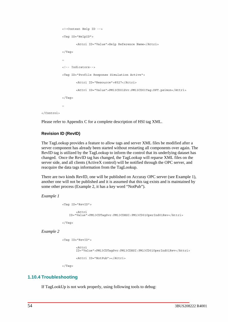
<!—Context Help ID -->
<Tag ID="HelpID">
<Attri ID="Value">Help Reference Name</Attri>
</Tag>
…
<!-- Indicators-->
<Tag ID="Profile Response Simulation Active">
<Attri ID="Resource">8527</Attri>
Attri>
…
</Control>
Please refer to Appendix C for a complete description of HSI tag XML.
up provides a feature to allow tags and server XML files be modified after a server component has already been started without restarting all components over again. The
g is utilized by the TagLookup to inform the control that its underlying dataset has Once the RevID tag has changed, the TagLookup will reparse XML files on the
will be notified through the OPC server, and a s information from the TagLookup.
OPC server (see Example 1), sumed that this tag exists and is maintained by
I:PM13CD01OperInd01Rev</Attri>
Example 2
1.10.4 Troubleshooting
If TagLookUp is not work properly, using following tools to debug:
<Attri ID="Value">PM13CD01Svr:PM13CD01Tag:DPT.psimon</
</Tag>
Revision ID (RevID)
The TagLook
RevID tachanged. server side, and all clients (ActiveX control)reacquire the data t g
There are two kinds RevID, one will be published on Accurayanother one will not be published and it is assome other process (Example 2, it has a key word “NotPub”).
Example 1
<Tag ID="RevID">
<Attri ID="Value">PM13CDTagSvr:PM13CDHS
</Tag>
<Tag ID="RevID">
<Attri ID="Value">PM13CDTagSvr:PM13CDHSI:PM13CD01OperInd01Rev</Attri>
<Attri ID=”NotPub”></Attri>
</Tag>
54 3BUS208222 R4001

3BUS208222 R4001 55
Task Manager
Check if server components are running normal ore information, see Task Manager on Troubleshooting.
Message Viewer (ABB Debug Client)
nd start the whole system.
See L files’ syntax is correct (for details on how to check XML syntax or parse XML
e whole system is not required.
essages, correct the errors follow th
For more information on how to use Debug Message, see Debug Message Viewer section on
Viewer
Open Windows Event viewer, see if there is any DCOM or license related information.
Refer to the DCOM section for DCOM setting.
Refer to the License Viewer on Troubleshooting section for detail description on how to check the OPC server and QCS applications license.
See Windows Event Viewer on Troubleshooting section for how to use it.
OPC Direct IT View
Open OPC Direct IT view on the client site to see if there are any missing tags or tags marked as bad quality. If any tags are undefined, correct the tag paths in tags and server XML file. After the problem is fixed, update the value of “RevID” in OPC Inspector, the TagLookUp will reparse the XML files (see the description of Revision ID (RevID) earlier in this TagLookUp section).
ect IT View for a complete description of how works.
tor
TagLookUp Viewer
There is a tool TagLookUpInfo.exe which is located on the network share “Paper Quality Control\bin” directory. This tool shows the information that is sent from the TagLookUp service.
ly. For m
Debug
Check if there are any messages from the TagLookUp (CABBTagsLookUpService).
If the error message is tag publishing related, make sure OPC server is running properly atags are correctly defined in XML file. After fixing the problem, re
If it is XML associated, check the tags and server XML file that specified in startup.xml. if the XMfiles see XML section). After fixing the problem, change the value of RevID in OPC Inspector, the TagLookUp will reparse the tags and server information XML files; a restartth
For other m e description on the debug viewer.
Troubleshooting.
Windows Event
See OPC Dir
OPC Inspec
For a complete description see OPC Inspector on Troubleshooting section.
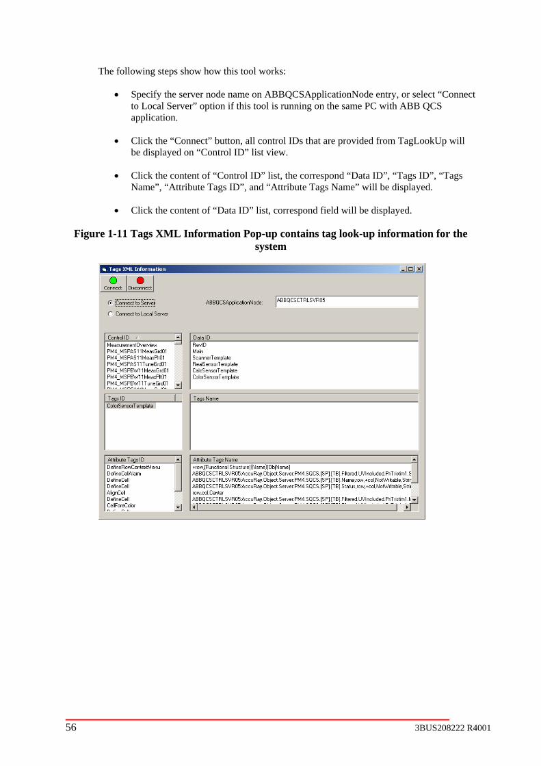
The following steps show how this tool works:
ct
• Click the “Connect” button, all control IDs that are provided from TagLookUp will d on “Control ID” list view.
s
Figur look-up information for the system
• Specify the server node name on ABBQCSApplicationNode entry, or select “Conneto Local Server” option if this tool is running on the same PC with ABB QCS application.
be displaye
• Click the content of “Control ID” list, the correspond “Data ID”, “Tags ID”, “TagName”, “Attribute Tags ID”, and “Attribute Tags Name” will be displayed.
• Click the content of “Data ID” list, correspond field will be displayed.
e 1-11 Tags XML Information Pop-up contains tag
56 3BUS208222 R4001

3BUS208222 R4001 57
1.11 Startup Engine
1.11.1 Overview
1.11.3
1.12 m Status Reporting
1.12.1
The Quality Control System Status Viewer displays the status of the Quality Control
1.12.2 Configuration
er is configured during the installation and configuration procedure when you run the BuildObjects.bat file (Refer to the Paper Quality
System Status Reporter Aspect. The values of the S_STATUS property have the following
Table 1-2 System Status Reporter S_Status property meanings
S_STATUS Meaning
1.11.2 Usage
Configuration
Syste
Overview
applications. Refer to the Troubleshooting Techniques section of this document for information on the System Status Viewer Aspect.
The Quality Control System Status View
Control Installation Guide). Each Quality Control Object that displays status information in the Status Viewer Aspect must have the properties S_STATUS and S_DESCRIPTION and a
meanings.
0 OK
1 Error
2 Warning
The S_DESCRIPTION property contains text describing the cause of the error or warnstatus.
ing
gs located either in the HealthWatch branch of the Quality Control OPC server or from the AC800M OPC Server. These tag values are moved to the property values by a Property Transfer Definition Aspect located on the Quality Control Object.
The following Aspects are used in supporting the Quality Control System Status Viewer Aspect.
Table 1-3 Aspects used to support Quality Control System Status Viewer Aspect
Aspect Function
The values of the S_STATUS and S_DESCRIPTION properties are obtained from OPC ta
QCStatus Pro Contains S_STATUS and S_DESCRIPTION ps
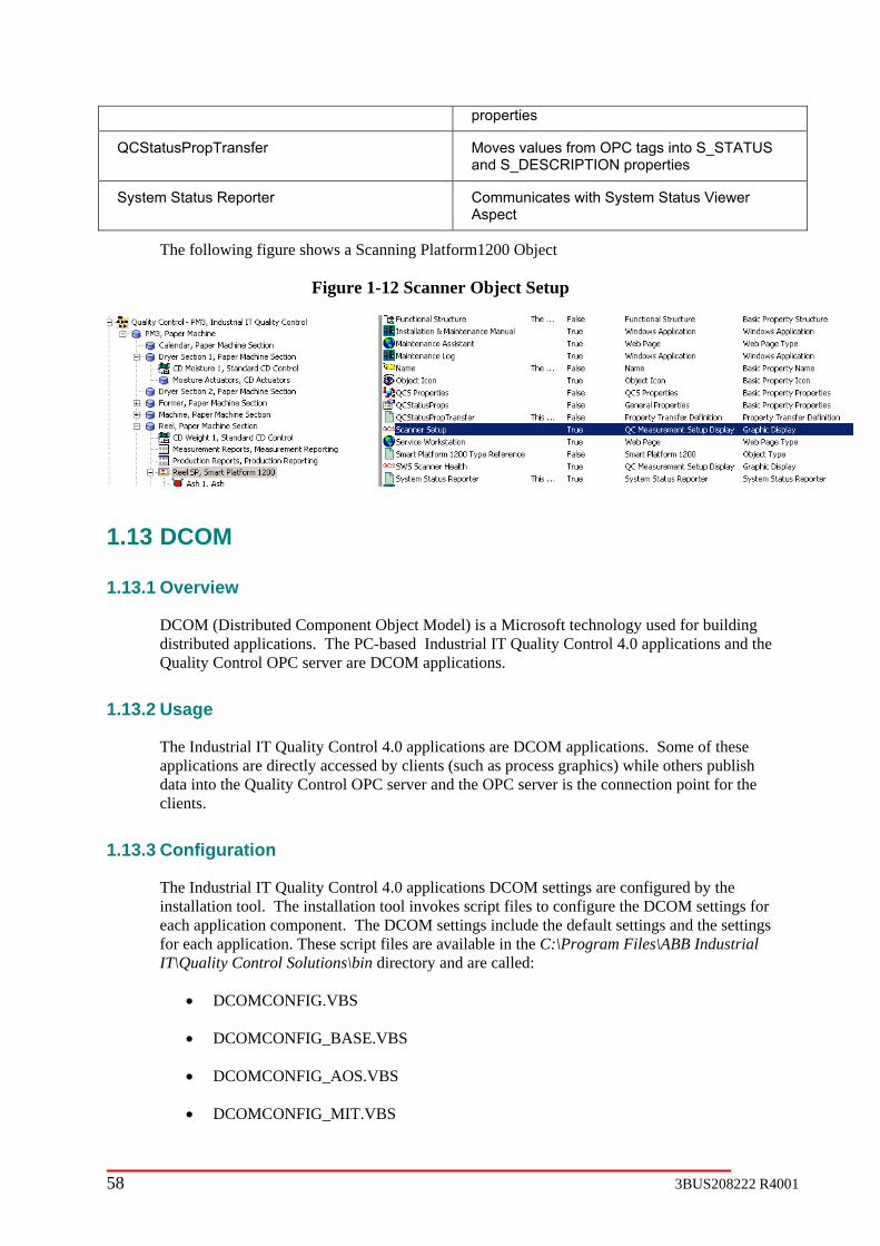
properties
QCStatusPropTransfer Moves values from OPC tags into S_STATUS and S_DESCRIPTION properties
System Status Communicates with System Status Viewer Aspect
Reporter
The following figure shows a Scanning Platform1200 Object
Figure 1-12 Scanner Object Setup
1.13
1.13.1
DCOM (Distributed Component Object Model) is a Microsoft technology used for building distributed applications. The PC-based Industrial IT Quality Control 4.0 applications and the Quality Control OPC server are DCOM applications.
1.13.2 Usage
The Industrial IT Quality Control 4.0 applications are DCOM applications. Some of these applications are directly accessed by clients (such as process graphics) while others publish data into the Quality Control OPC server and the OPC server is the connection point for the clients.
1.13.3 Configuration
The Industrial IT Quality Control 4.0 applications DCOM settings are configured by the installation tool. The installation tool invokes script files to configure the DCOM settings for each application component. The DCOM settings include the default settings and the settings for each application. These script files are available in the C:\Program Files\ABB Industrial IT\Quality Control Solutions\bin directory and are called:
• DCOMCONFIG.VBS
• DCOMCONFIG_BASE.VBS
• DCOMCONFIG_AOS.VBS
• DCOMCONFIG_MIT.VBS
DCOM
Overview
58 3BUS208222 R4001

3BUS208222 R4001 59
.VBS
Only System Administrators with experience of DCOm should run these scripts.
• DCOMCONFIG_CLIENT

Chapter 2 Aspects and Objects
2.1 Overview The Industrial IT Quality Control 4.0 Objects and Aspects are packaged as a system extension in the same manner as other system extension such as the AC800M system extension. The
spects for all Quality Control
The Industrial IT Quality Control 4.0 Objects and Aspects are intended to be integrated into er ABB Objects for product and process objects. The Pulp & Paper a common framework for all ABB Pulp and Paper products.
ol h
.2 ture ome pes.
2-1 Object Type Structure example
Quality Control system extension contains all of the ActiveX controls, DLLs and afw files making up the Industrial IT Quality Control 4.0 Objects and Afeatures.
the ABB Pulp & PapObject types provide
The Installation and Job Order Configuration process, described in the Paper Quality ContrInstallation and Configuration Guide, automatically populates the Functional Structure witthe Quality Control Objects required for the system configuration.
2 Object Type StrucThe Industrial IT Quality Control 4.0 Objects are defined in the Object Type Structure. Sfeatures implement template objects which are used as the inheritance base for specific ty
The illustration below illustrates the concept but is not an actual implementation.
Figure
2 Aspect categories and .3 Filtering The IndustrialIT platform provides the ability to filter aspects by aspect category. It is possible to define multiple filters and to assign filters to individual users. The filter affects the aspects that are visible in context menus, application bar shortcut menus and other navigation schemes.
60 3BUS208222 R4001

cs.
1. System Process Display
9. CD Process Display
2.4 The Quality Control graphics displays provide a mechanism by which properties can be set and the Con implementation uses special Process Graphic Aspect Categories with additional logic to invoke code contained in the ARGraphicAssist DLL. Each QC ABB Object m pecial pro ies. The ARGraphicAssist DLL will set properties of the sam ols contained in the process graphic and invoke the Co propriat
The ARGraphicAssist DLL first applies the QC rol ob n the locgraphic aspect). The properties defined on the local object have precedence because they are applied last. After applying all properties, the ARGraphicAssist DLL calls the Connect / QC ontrol
The following aspect categories are used to implement Quality Control process graphi
2. System Setup Display
3. Measurement Process Display
4. Measurement Setup Display
5. Color Process Display
6. Color Setup Display
7. MD Process Display
8. MD Setup Display
10. CD Setup Display
11. ABB Engineer Display
Quality control aspect functionality
nect and Disconnect methods can be invoked at run-time. This
ay contain a sperties aspect of category QCS Propert
e name on ActiveX contrnnect / Disconnect methods at the ap e times.
S Properties on the root Quality Contject and then applies the properties o al object (object containing the process
SConnect methods on each ActiveX c .
3BUS208222 R4001 61
2.5
2.5.1 Overview
2.5.2 Tag Lookup
2.6 Grade Code Handling
2.6.1 Overview
2.6.2 Usage
2.6.3 Configuration
2.7 Coldstart File Handling
2.7.1 Overview
2.7.2 Usage
2.7.3 Configuration
2.8.1 Overview
stanprorela
1. Control IT IEC 61131 Control Languages Introduction, (3BSE 021 358 R201 Rev B)
2. Engineer IT Control Builder M Version 3.2 Getting Started Introduction and
4. Control IT AC 800M/C Version 3.2 Alarm and Event Handling Objects and Design (3BSE 028 808 R201)
Process Graphics
2.8 MD Control
The MD control features are implemented in the AC800M controller using the IEC-61131 dard control language. For detailed description of the AC800M controller hardware and
gramming structure refer to the ControlIT documentation set. The most relevant manuals ted to the MD control implementation are:
Installation (3BSE 028 807 R201 Rev B)
3. Engineer IT AC 800M/C Version 3.2 Application Programming Strategy and Design (3BSE 028 765 R201 Rev B)
62 3BUS208222 R4001

5. Control IT AC 800M/C Version 3.2 Analog Process Control Objects and Design (3BSE 028 809 R101 Rev B)
6. Control IT AC 800M/C Connect Version 3.2 Integration to Process Portal A Configuration and Engineering (3BSE 028 812 R201 Rev A)
7. Control IT AC 800M Version 2.1 Controller Hardware and Operation (3BSE 027 941 R201)
The MD control features are implemented using two of the five IEC-61131 languages which are FBD (function block diagram) and ST (structured text).
2.8.2 Configuration
The following section outlines the general configuration of the MD control features. MD control is composed of the several general configuration files which are AC800M control project, AC800M control libraries, operator interface configuration, default tuning and configuration data, OPC transporter configuration, and project configuration file.
AC800
uality
r IT Data\Control Builder M Professional 3.2\Projects\PM4MD01”. There should be no reason to modify any of the files in the AC800M control project.
The projemachine ID). The controller hardware configuration file as “Controller_machineidNOD01.con”)
AC800M Control Libraries
he AC800M control libraries are copied from the QCS control IT directory (C:\Program Files\ABB Industrial IT\Quality Control Solutions\Control IT\MD Control\Libraries) to the
ory (C:\ABB Industrial IT Data\Engineer IT Data\Control
ct ed
ct directory a prompt will appear asking if the libraries should be over written.
Op
detafiles server definition file (e.g. PM4MD01_TagsServer.xml) and the actual OPC tag file (e.g. PM4MD01_Tags.xml). Both of
M Control Project
The AC800M control project is created during the installation by running the “MD Open Interface Project Create Tool” under Start -> Programs -> ABB Industrial IT -> QControl Solutions -> Control IT. The project can normally be found under the directory “C:\ABB Industrial IT Data\Enginee
ct file is created as “Application_machineidMD01.app” (machineid is the paper
T
AC800M control project directBuilder M Professional 3.2\Projects\Libraries) when the AC800M control project is created. The run time control project uses the libraries that are located in the AC800M control projedirectory. When the “MD Open Interface Project Create Tool” is run the libraries are copito the project directory if they don’t already exist in this location. If the libraries already exist in the AC800M control proje
erator Interface Configuration
All of the MD displays are based on the Taglookup interface which allows the OPC tags that are displayed to be easily changed by editing the MD display XML configuration file. A
iled description of the TagLookup interface can be found in section 1.10. There are two for the MD control display configuration which are the
3BUS208222 R4001 63

thes fil under the directory “C:\Program Files\ABB Industrial IT\Q al tions\Control IT\MD Control\HSI”.
Default Tuning and Configuration Data
After the MD control project has been created with the “MD Open Interface Project Create Tool” default tuning and configuration data can be loaded into the controller. The default tuning file contains a set of tuning values that can be used for operator training or software verification. The default tuning is a starting poito b ad b order configuration data into the controller. Both the default tuning and configuration data
The l) and configuration data file (e.g. PM4MD01_DefaultConfig.xml) are normally located in the folder “C:\Program Files\ABB Industrial IT\Quality Control Solutions\Control IT\MD Control\data”.
OPC Transporter Configuration
llAC n file (e.g. PM4MD01_L2Transporter.xmIndustrial IT\Quality Control Solutions\Control IT\MD Control\OPC”. A detailed description of the OPC transporter can be found in section 1.8. The following table summarizes the transporter groups that are configured for MD control.
Table 2-1: OPC Transporter Groups for MD Control
Group Name (machineid – paper machine ID from
job order configuration)
Description
e e are normally locatedu ity Control Solu
nt for the MD control tuning but is not meant e used for actual customer control loop tuning. The configuration data is used lo jo
files only need to be loaded once in the controller. After these files have been loaded the controller data will be saved in the AC800M project cold retain data files.
default tuning data file (e.g. PM4MD01_DefaultTune.xm
A of the level 2 scanner measurements and grade data are transferred to and from the 800M controller through the OPC transporter interface. The OPC transporter configuratio
l) is located in the folder “C:\Program Files\ABB
machineid_MDMeasDataToAC800 Level 2 measurement from measurement signal processing to AC800M OPC server
machineid_MDGCMDataToAC800 Grade data from QCS object server to AC800M OPC server
machineid_MDGCMDataFromAC800 Grade data target from AC800M OPC server to rver QCS object se
Project Configuration File
The MD control pro configuration tool and is used by the “MD Open Interface Project Create Tool” when creating the MD control project
“C:Control\config”. When the MD AC800M project is create a text file is also created (MD_AddedVariables.txt) which provides a list of any additional variables that were created
the MD open interface tool that were needed based on the job order configuration. The only time this file should contain variable names is when process tag names were defined in the job order configuration level 1 measurement or level 1 control worksheets and are not
ject configuration file is create by the job order
file for the AC800M. This file (e.g. PM4MD01_Project.xml) is normally located in the folder\Program Files\ABB Industrial IT\Quality Control Solutions\Control IT\MD
by
64 3BUS208222 R4001

ayed dur venot found in the I/O worksheets. An example of this message is shown in the following figure.
contained in the Excel I/O worksheets. When this condition exists a message is also displing the MD project creation that gi s the user the option to create the variables that were
igure 2-2: Example of MD Project Create Tool Message for Variable Name Discrepancy
F
2.8.3
After the job order configuration has been deployed and the installation procedure has been completed the following items can be used to verify MD control configuration is complete.
• Using Plant Explorer check the System Status Viewer display on the main QCS object “Ind e MD control features should all be green and “OK”. Only the MD feature configured should be displayed. The available MD control features include Level 1 Control, Drystock, Headbox, Scan Level Control, Speed Control, Auto Grade Change, and Dryer Control.
Configuration Verification
ustrial IT Quality Control”. Th
3BUS208222 R4001 65

Figure 2-3: Example of Status Viewer
ional structure the MD control objects should appear under Q1. Under the funct uality Control – PMx ->PMxthis feature functional structure is shown in the following figure.
-> Machine. Headbox control may be under a different object based on what section was assigned to in the job order configuration. An example of the MD object in the
Figure 2-4: Example of MD Objects in Functional Structure
programs should all appear below the Application 2. Under the Control Structure the MD control objAppstru
ect (e.g. Root -> Control Network -> Application_PM4MD01 -> Applications -> lication_PM4MD01 -> Programs). The following figure shows an example of the control cture for the MD control programs.
66 3BUS208222 R4001
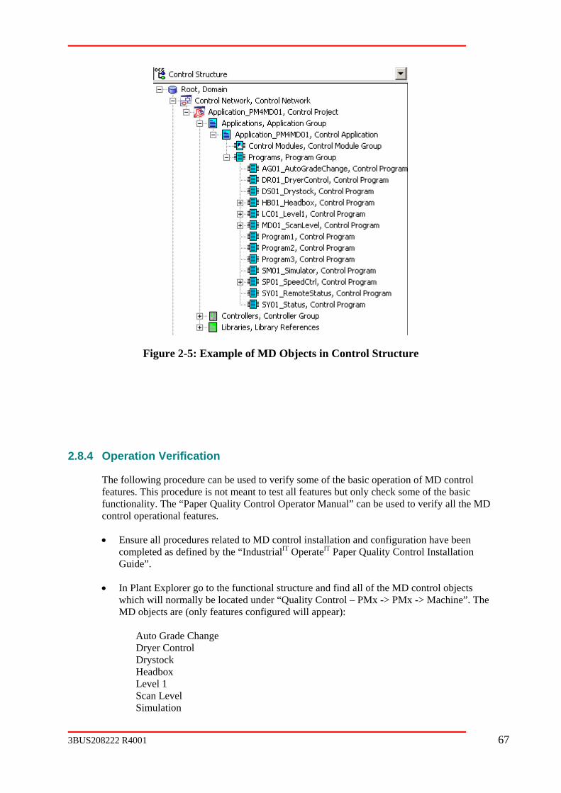
Figure 2-5: Example of MD Objects in Control Structure
Operation Verification
The following procedure can be used to verify some of the basic
2.8.4
operation of MD control features. This procedure is not meant to test all features but only check some of the basic function y Control Operator Manual” can be used to verify all the MD control operational features.
• Ensure all procedures related to MD control installation and configuration have been com strialIT OperateIT Paper Quality Control Installation Guide”.
• In Plant Explorer go to the functional structure and find all of the MD control objects whi ed under “Quality Control – PMx -> PMx -> Machine”. The MD objects are (only
Level 1 Scan L Simulation
ality. The “Paper Qualit
pleted as defined by the “Indu
ch will normally be locat features configured will appear):
Auto Grade Change Dryer Control Drystock Headbox
evel
3BUS208222 R4001 67

Spee
trol object select each
d Control
On each MD con MD display aspect (look for QCS icon ). isplay shows data.
• Go to the simulation setup display and tion Enable check boxes. After 5 to 10 seconds clearemaining check boxes as shown in the following figure.
Verify that each d
check the Simulation Reset and Simular the Simulation Reset check box. Set the
Figure 2-6: Simula
• ect and MD C eft click once on the mode display of one of the ppear. Right click on the mode and a menu sh
tion Configuration
Go to the Scan Level obj ontrol Overview display should appear. L level 1 controllers and a faceplate should aould appear that allows the mode to be changed.
Figure 2-7: Exa
mple Faceplate
68 3BUS208222 R4001

Figure 2-8: Example Right Click Menu
• Place the Stock flow in Auto mode and then enter a setpoint on the weight control close to the current measurement (measurement frame should be scanning or frame simulation should be enabled).
• Place the weight control in Auto and the stock flow should go to E1.
• Chamanual ator
nge the stock flow back to Auto mode and the weight control should go back to and a red alarm indic should appear. The alarm list should also have a new
alar
• Right click the weight control alarm indicator and then select the MD_Abort_Suspend men rred.
2.9 CD Con
2.9.1 Overview
Sheet prope e sensor measurements that vary in both thedirectioCD control actions to CD actuators (e.g. headbox slice, water spray, and infrared dryer). The control requires existence of a scanner and measurement sub-system, and a CD actuator sub-system
ed tasks.
for deployment in an ABB QCS Server. The control o handle data flow via an OPC Transporter service
l
, e OPC
In total, the CD QCS Application Fra up and to expose its OPC data to other ABB QCS applications:
m for the weight control abort.
u item which should open a display that identifies the abort condition that occu
trol
rties such as weight, moisture and caliper hav machine-direction (MD) and cross-machine direction (CD). MD is defined as the n of sheet travel, whereas CD is defined as the direction perpendicular to the MD. A
is an application designed to correct variations in the CD by applying control
to perform its intend
CD control is designed as a soft controlis implemented with an OPC interface twith the scanner and measurement sub-system, and the CD actuator sub-system. This controimplementation methodology requires that the two sub-systems, to which the CD control passes data, have their tags available in an OPC server. For the integrated ABB QCS solutionthis requirement is fulfilled to the extent of creating the XML documents needed by thTransporter service for passing data back and forth.
control application is dependent on the following ABBmework to start
1. QC Object Server
3BUS208222 R4001 69
2. ABB QCS Service
3. OPC Transporter service
PC Publis
5. TagsLooku
6. ABB Healt
2.9.2 Application Frame
ABB QCS Service
ABB QCS service is us rver machine, in wh control exist artup.xmdocument by the job or rol application:
<component class="PCCDControls" ID="PCDControl1"> ABBCDContr <param rgID="Conf IT \CD <param argID="Erro</component>
In the above code exam e “server_name” is the machine name of the ABB QCS Server, in control ex d in the job ordconfiguration.
The main roll of ABB Q
7. Pass the configuration file corresponding to the “ConfigFile” parameter and launch the
the CD control application of successful startup of the QC Object Server t the
quest ter QCS Service is stopped.
OP
OP t e CD co ublishing software application. D for each of the control instance present in the server machine. The following OPC branch structure is used to
rganize the published tags
- PMx - CDControls - - CD01 (1 instance of CD control) - Act + Act1 (interface tags to true actuator system) + Sim1 (interface tags to CD process response simulator) - Meas
4. O hing
p
h Watch
work Dependencies
ed to launch the CD control application when the seich CD s, is started up. The following entries are added to the st
der configuration tool to schedule startup of the CD contl
<progID>a
ol.CABBBasCDSupervisor</progID> igFile">\\server_name\Paper Quality Control\Control Control\config\PMxCDMasterConfig.xml</param> rFile">ErrorLog.log</param>
ple, thwhich CD ists, and “PMx” is the paper machine label assigne
CS Service includes the following:
CD control class “CABBBasCDSupervisor”.
er
8. Notifyso tha
9. Re
CD control application can publish its OPC tags.
mination of the CD control application when the ABB
C Publishing
C ags for th ntrol are created in the QC Object Server by the OPC Puring startup, the CD control application publishes tags
o
Standard st
70 3BUS208222 R4001
terface tags to true frame and sensor system) + Sim1 (interface tags to CD process response simulator)
02 (2 instance of CD control) + CDnn (n-th instance of CD control)
where “PM achine label assigned in the job order configuration and “nn”, in “CDnn”, is
In the above branch structure, the “-” denotes branches that are fully expanded and the “+” denotes branches that are collapsed. The actual published tags exist under the branches “Act1”, “Meas1”, “Sim1”, “DPT”, and “SPT”. At startup, the tags under branches “DPT” and “SPT” are c s. All other tags are initialized to the value of zero. The tags under branches “Act1”, Meas1” and “Sim1” are created without initialization, resulting in a tag quality of “uncertain”. The tag quality rem n to either by an internal write from the CD control or an external write by a client application.
OPC T
The OPC Tapplication simulation) nsporter
12. PMxCDnnGDXPort.xml
13. PMxCDnnSimXPort.xml
g
C:\Program Files\ABB Industrial IT\Quality Control Solutions\Control IT\CD Control\OPC
XML documents that can be validated by the OPCTransporter.dtd scheme and are placed in this direc matically s e OPC Transporter service when the QCS Server node starts up. The fourth XML file in the above list is intentionally left out of the active pr artup lation tra
TagsLookup
The TagsLookup component is used to define groups of OPC tags (call ControlID) to interface with specialized ActiveX controls. These ActiveX controls generate OPC Direct groups with the tag information formatted in the ControlID’s. The ControlID format further provides visual presentation instructions to the ActiveX control. In total, CD control visual aspects are created from the following list of ActiveX controls:
+ Meas1 (in
+ DPT (scalar data in the CD control application) + SPT (array data in the CD control application + CD nd
x” is the paper m a two character numbering instance of the CD control.
reated and initialized. Tags that are tuning parameters are set to persisted value
ains “uncertain” until it is writte
ransporter Service
ransporter service is used by the CD control to move data between the control and other QCS applications (e.g. CD actuator, frame, sensor, grade data and . The job order configuration tool generates the following four types of tra
XML documents for each CD control instance:
10. PMxCDnnMeasXPort.xml
11. PMxCDnnActXPort.xml
Additional information about these XML documents is provided in section 2.9.3.
The first three types of transporter files are copied to a directory that has been registered as an active processing path for the OPC Transporter service. For CD control, the active processinpath is typically
tory are auto tarted by th
ocessing path to avoid st of simu nsporters.
3BUS208222 R4001 71

1. ABBAutoPlotCtl
Grid
3. ABBCommandButtons
4. ABBIndicator
5. ABBCDMapping
CD control operator and engineering information is captured in 11 visual aspects. Table 2-2 presents the visual aspects and identifies the Tag of the ActiveX controls used on these aspects.
Table 2-2: CD control Tags
Aspect Name ActiveX Control and ControlID
2. ABBAutoCfg
6. ABBMSFlexGrid_TL
sLookup ControlID’s corresponding to each
Lookup ControlID
Control Overview ABBABBABBABBABB
AutoPlotCtl: PMxCDnnOperPlt01 AutoCfgGrid: PMxCDnnOperGrd01 AutoCfgGrid: PMxCDnnOperGrd02 Indicator: PMxCDnnOperInd01 CommandButtons: PMxCDnnOperCmd01
Profile Target ABBABBABBCommandButtons: PMxCDnnTargCmd01
AutoPlotCtl: PMxCDnnTargPlt01 AutoCfgGrid: PMxCDnnTargGrdTL01
Actuator to Profile Mapping ABBABBABB ABB CDnnMappCmd02 ABBABB
AutoCfgGrid: PMxCDnnMappGrd01 AutoCfgGrid: PMxCDnnMappGrd02 CommandButtons: PMxCDnnMappCmd01CommandButtons: PMxIndicator: PMxCDnnMappInd01 CDMapping: PmxCDnnMappPix01
Control Tuning ABBABBABBAutoCfgGrid: ABBAutoCfgGrid: PMxCDnnTuneGrd04
AutoCfgGrid: PMxCDnnTuneGrd01 AutoCfgGrid: PMxCDnnTuneGrd02
PMxCDnnTuneGrd03
Profile Processing ABBABB
AutoPlotCtl: PMxCDnnFiltPlt01 AutoCfgGrid: PMxCDnnFiltGrd01
Spatial Response Model ABBABBAutoCfgGrid: RespGrd01 ABB
AutoPlotCtl: PMxCDnnRespPlt01 PMxCDnn
CommandButtons: PMxCDnnRespCmd01
Bumptest Setup ABBABBABBAutoCfgGrid: PMxCDnnABBABB Cmd02
AutoCfgGrid: PMxCDnnBmp1Grd01 AutoCfgGrid: PMxCDnnBmp1Grd02
Bmp1Grd03 Indicator: PMxCDnnBmp1Ind01 CommandButtons: PMxCDnnBmp1
72 3BUS208222 R4001

ActiveX Control and ControlID Aspect Name
Bumptest Analysis ABBAutoPlotCtl: PMxCDnnBmp2Plt01 ABBAutoPlotCtl: PMxCDnnBmp2Plt02 ABBAutoCfgGrid: PMxCDnnBmp2Grd01 ABBAutoCfgGrid: PMxCDnnBmp2Grd02 ABBCommandButtons: PMxCDnnBmp2Cmd01
Setpoint Save/Restore ABBAutoPlotCtl: PMxCDnnSetpPlt01 ABBAutoCfgGrid: PMxCDnnSetpGrd01 ABBCommandButtons: PMxCDnnSetpCmd01 ABBCommandButtons: PMxCDnnSetpCmd02
Edge Handling ABBAutoPlotCtl: PMxCDnnEdgePlt01 ABBAutoCfgGrid: PMxCDnnEdgeGrd01
id: PMxCDnnEdgeGrd03 PMxCDnnEdgeCmd01
ABBAutoCfgGrid: PMxCDnnEdgeGrd02 ABBAutoCfgGrABBCommandButtons:
Shee ABBAutoPlotCtl: PMxCDnnSBrkPlt01
nSBrkGrd03 ABBAutoCfgGrid: PMxCDnnSBrkGrd04
tbreak Recovery ABBCommandButtons: PMxCDnnSBrkCmd01 ABBAutoCfgGrid: PMxCDnnSBrkGrd01 ABBAutoCfgGrid: PMxCDnnSBrkGrd02 ABBAutoCfgGrid: PMxCDn
ABB Heal
The ABB H ding the CD control application. The status information for each CD control instance is reflected on the PPA Status Report Viewer by a symbol and text messages. CD control exposes the followin t BB HealthWatch component:
1.
2. nse could not be obtained for the CD control instance
3. OPC Error – tag publishing or connection to the OPC server could not be
atchdog Error – OPC Transporter service did not detect a heartbeat signal from the corresponding measurement system or actuator system in the allotted time period
did not receive a new watchdog update from the OPC Transporter service in the allotted time period for the connection to
or actuator system
6. ny of the ML
th Watch
ealthWatch component is accessed to report both good and bad status regar
g s atus information to the A
Application Heartbeat – a value generated by CD control that is periodically incremented by one
Application License Error – a valid lice
established
4. Transporter W
5. Transporter Update Error – CD control
the measurement system
Application Startup Error – CD control could not be started up due to aabove error conditions or because of a bad CD control master configuration Xfile
3BUS208222 R4001 73

2.9.3 Config a
Required
The job ordCD control.for each CD control instance being configured. In Figure 2-9, the “Figure Reference” numbers shown in Table 2-3 are identified as callouts, outlined with a box.
Table 2-3: CD control job order information
Configuration Description Figure Referenc
e
ur tion
Job Order Information
er configuration tool is used to configure all the necessary XML documents for In order to achieve this task, the information presented in Table 2-3 is required
Labels
CD Type The CD type field defines the application for which the CD control instance is bselected from an option list that includes CD Weight,
1 eing configured. The type is
e, CD Caliper, CD Coat Weight, CD Gloss, oothness. The type should be chosen in
CD Moisturand CD Smaccordance to the features appearing in the purchase order. The configured CD types will be checked for valid licenses.
Descriptiidentifying the CD control instance. This description will be captured in the functional structure of PPA.
on The description field is a user-defined entry for 2
Node The node field identifies the QCS server name where the CD control instance is to reside. The node name is selected from a list of names that are entered in the “Nodes” tab of the configuration tool.
3
Actuator The actuator field identifies the profiling actuator that the CD control instance is interfaced to. The selection of actuator is selected from a list of names that are entered in the “CD Actuators” tab of the configuration tool.
4
Machine Secti
machine section will be the location in the PPA functional structure for placement of all aspects
on The machine section field identifies the machine processing section that the CD control instance is most closely associated with. The machine section is selected from a list of names that are entered in the “General” tab of the configuration tool. The selected
5
associated with the CD control instance.
MeasureID (1st profil ontrol instance. The measurement ID is
selected from a list of sensor names that are entered
ment
e)
The 1st profile (primary) measurement ID field identifies a sensor profile name that is controlled by the CD c
6
in the “Measurement” tab of the configuration tool.
74 3BUS208222 R4001

ConLabels
Figure figuration Description Referenc
e
Measurement ID (2nd p
If desired, the 2nd profile (secondary) measurement ID
selected from a list of sensor names that are entered
7
rofile) field identifies a sensor profile name that is controlled by the CD control instance. The measurement ID is
in the “Measurement” tab of the configuration tool.
1
2
3
5
4
6
7
1
2
3
5
4
6
7
Figure 2-9: CD control job order configuration tab
Deployment Directory Structure
When a project job is deployed, the configuration tool copies all XML documents related to CD control into predetermined CD control application directories. These application directories include
7. ..\Control IT\CD Control\config Includes a configuration file for starting up all CD control instances and CD simulation files.
8. ..\Control IT\CD Control\data Includes tuning persistence files, setup files and log files for each CD control instances.
9. ..\Control IT\CD Control\HSI Includes TagsLookup definition files for each CD control instances.
3BUS208222 R4001 75
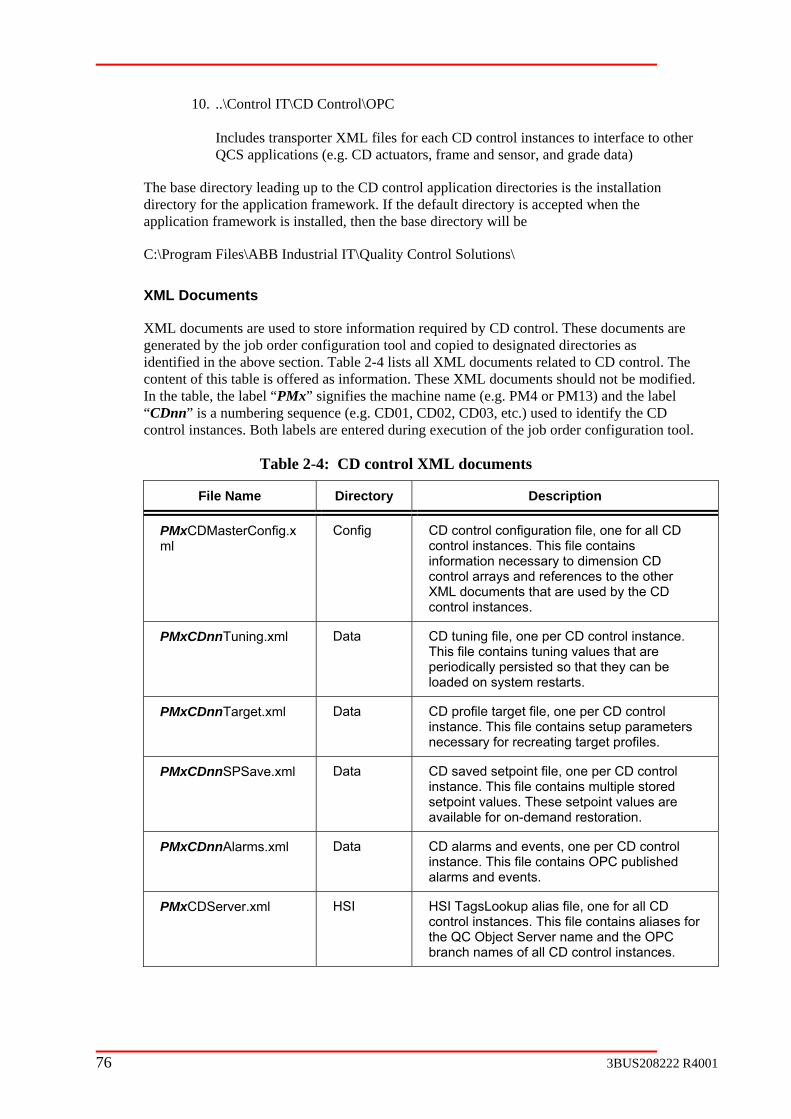
10. ..\Control IT\CD Control\OPC Includes transporter XML files for each CD control instances to interface to other QCS applications (e.g. CD actuators, frame and sensor, and grade data)
The base directory leading up to the CD control application directories is the installation directory for the application framework. If the default directory is accepted when the application framework is installed, then the base directory will be
C:\Program Files\ABB Industrial IT\Quality Control Solutions\
XML Documents
XML documents are used to store information required by CD control. These documents are generated by the job order configuration tool and copied to designated directories as identified in the above section. Table 2-4 lists all XML documents related to CD control. The content of this table is offered as information. These XML documents should not be modified. In the table, the label “PMx” signifies the machine name (e.g. PM4 or PM13) and the label “CDnn” is a numbering sequence (e.g. CD01, CD02, CD03, etc.) used to identify the CD control instances. Both labels are entered during execution of the job order configuration tool.
Description
Table 2-4: CD control XML documents
File Name Directory
PMxCDMasterConfig.xml
Config CD control configuration file, one for all CD control instances. This file contains information necessary to dimension CD control arrays and references to the other XML documents that are used by the CD control instances.
PMxCDn
periodically persisted so that they can be loaded on system restarts.
nTuning.xml Data CD tuning file, one per CD control instance. This file contains tuning values that are
PMxCDnnTarget.xml Data CD profile target file, one per CD control s setup parameters instance. This file contain
necessary for recreating target profiles.
PMxC control
e for on-demand restoration.
DnnSPSave.xml Data CD saved setpoint file, one per CD instance. This file contains multiple stored setpoint values. These setpoint values are availabl
PMxCDn
nAlarms.xml Data CD alarms and events, one per CD control instance. This file contains OPC publishedalarms and events.
PMxCDScontrol instances. This file contains aliases for the QC Object Server name and the OPC branch names of all CD control instances.
erver.xml HSI HSI TagsLookup alias file, one for all CD
76 3BUS208222 R4001

File Name Directory Description
PMxCDnnTags.xml HSI HSI TagsLookup tag definition file, one per CD control instance. This file contains all the OPC tags (organized as ControlID) necessary to support the visual aspects created for CD control.
PMxCDnnMeasXPort.xml
OPC Frame and sensor transporter file, one per CD control instance. This file contains transporters for passing frame and sensor data to the CD control.
PMxCDnnActXPort.xml
OPC Actuator transporter file, one per CD control instance. This file contains transporters for passing actuator setpoints, actuator feedback, zone status, and actuator system status between the CD control and the actuator system.
PMxCl
e per CD control instance. This file contains a transporter for passing grade dependent CD tuning values on a grade change (automatic
DnnGDXPort.xm OPC Grade data transporter file, on
or manual) event.
PMxCDSimConfig.xml Ccontrol instances. This file contains parameters for defining the actuator system
onfig CD simulator configuration file, one for all CD
, frame system and profile response.
PMxCDnnSimXPort.x Config CD simulator transporter file, one per CD control instance. This file contains transporters for passing simulated frame,
CD
ml
sensor and actuator data to and from thecontrol.
2.9.4
by OPC transporters. The following sections identify the specific transporter groups created by the job
ring frame and sensor data to CD control
easXPort.xml
Transports data from the frame (“SP” branch) to CD control. Transported data
Interface to Dependent Application
Data transfer between CD control and other QCS applications is achieved entirely
order configuration.
Frame and Sensor Transporters
The transporter XML document created for transferis
PMxCDnnM
This transporter document contains only unidirectional transporter groups. The transporter groups contained within and their function are as follows:
1. PMxCDnnMSPFrame
3BUS208222 R4001 77

includes databox width, home frame limit, home sheet position, far sheet positauto-ed
ion, ge-of-sheet status, and current frame head position
Transports data from time-based measurement (“CONTROLMEAS” branch) to orted data includes scan time, number of databoxes, frame
offsheet status, frame sheetbreak status, first databox number with profile data, with profile data, high-resolution profile, and profile
average.
3. PMxCDnnMSPMeas2
if a second profile measurement is assigned ol. Transports data from time-based measurement
rol. Transported data includes high-d profile average.
document created for transferring actuator data with CD control is
Transports data from CD control to actuator (“CDActuators” branch).
dback, bad actuator status, bad measurement feedback status, actuator not moveable status, actuator in local
Grade Data Transporter
The transporter XML document created for transferring grade data to CD control is
PMxCDnnGDXPort.xml
n and its function is as follows:
PmxCDnnGradeData
2. PMxCDnnMSPMeas1
CD control. Transp
last databox number
This transporter group is created onlyto the CD contr(“CONTROLMEAS” branch) to CD contresolution profile, an
Actuator Transporters
The transporter XML PMxCDnnActXPort.xml
This transporter document contains bi-directional transporter groups. The transporter groups contained within and their function are as follows:
1. PMxCDnnActOutput
Transported data includes new actuator setpoints generated automatically or manually from the CD control.
2. PMxCDnnActInput
Transports data from actuator (“CDActuators” branch) to CD control. Transported data includes actuator measurement fee
status, actuator request to suspend CD control flag, actuator request to abort CD control flag.
This transporter document contains a unidirectional transporter group. The transporter group contained withi
1.
78 3BUS208222 R4001

ata from grade data (“SQCS.GD” branch) to CD control. Transported
ors, control high and low setpoint limits, setpoint 1 and 2
2.9.5
After the job order configuration has been deployed and the installation procedure has been ol by ABB QCS Service can be monitored in the ABB Debug ample of the ABB Debug Client with messages related to
trol
stem. Config file: \\…”
sult of ABB QCS Service launching the CD control configuration file.
ed for each CD control instance, indicating creation of a
essage is displayed for each CD control instance, indicating internal s and tuning value.
CDnn.”
of the CD control startup is
rvisor: Checking license for CD Control package CDnn.”
ayed for each CD control instance, indicating that license is
Transports ddata includes CD response model, setpoint smoothing factor, tuning gains, MD and CD filter fact st nd
order difference limits, maximum setpoint change limit, and non-linear mappingtable.
Verify Configuration and Operation
QC Server Node
completed, startup of CD contrClient. Figure 2-10 gives an exstartup of the CD control application. In the client window, a successful startup of CD conwill generate the following messages in sequence:
1. “CABBBasCDSupervisor: Beginning startup of CD sy This message is displayed as resupervisor class and passing it the
2. “CABBBasCDSupervisor: Begin creating new CD control instance.” This message is displayCD control object.
3. “CABBBasCDSupervisor: Initializing CD Control package CDnn.” This minitialization of array
4. “CABBBasCDSupervisor: CD Control package CDnn initialized.” This message is displayed for each CD control instance, indicating completion ofinternal initialization.
5. “CABBBasCDSupervisor: Publishing tags for CD Control package This message is displayed for each CD control instance, indicating creation of OPC tags in the QC Object Server. This step postponed until the ABB QCS Service notifies the CD supervisor that the target QC Object Server has successfully started up.
6. “CABBBasCDSupe This message is displbeing checked.
3BUS208222 R4001 79

7. “CABBBasCDSupervisor: Connecting to OPC Server for CD Control package CDnn.”
This message is displayed for each CD control instance, indicating that the CD se
8. “CABBBasCDSupervisor: CDnn started successfully.”
This message is displayed for each CD control instance, indicating successful of the CD cont
control application has established a link with the QC Object Server. If a licenfor the CD control instance could not be validated, the connection to the QC Object Server is not performed.
startup rol instance.
Figure 2-10: ABB Debug Client for startup of CD control
Process Portal Functional Structure
After the job order configuration has been deployed and the installation procedure has been completed the following itemcomplet
s can be used to verify that PPA configuration for CD control is e.
1. Using Plant Explorer, check the System Status Viewer display on the main QCS object “Industrial IT Quality Control”. The CD control features should all have a green circle in the “Status” column. Only the CD control features configured should be displayed. In Figure 2-11, “Dilution CD Weight” and “CD Moisture” are shown as examples.
80 3BUS208222 R4001

Figure 2-11: Status viewer example for CD control
“Quality Control - PMx, Industrial IT Quality Control > PMx, Paper Machine >
achine Section”
configuration tool. In the aspects lists, 11 visual aspects should be present. In t” and “CD Moisture” are shown as examples.
2. In the functional structure, the CD control objects should appear under
Machine Section, Paper M where “PMx” is a label for the paper machine and “Machine Section” is a label for process section. These labels are created during execution of the job order
Figure 2-12, “Dilution CD Weigh
Machine Section
CD Type Description Visual Aspects
Machine Section
CD Type Description Visual Aspects
Figure 2-12: Functional structure example for CD Control
Error/Event Log File
An error and event log file is maintained for each CD control instance. This log file is typically created in the directory C:\Program Files\ABB Industrial IT\Quality Control Solutions\Control IT\CD Control\data with the naming convention PMxCDnnErrorLog.log,
3BUS208222 R4001 81

where “PMx” is a m Dnn” is a numbering sequence (e.g. CD01, CD02, CD03, etc.) used to identify the CD control instances.
The log file is erased on restart of the CD control application and is populated with messages fr art. T ent of the log file includes the startup sequence messages, application code error, transporter errors, an
If the content of the log file is important for troubleshointo a safe location before restarting the CD control apparagraph, the log file is erased on restart of the CD co
2.10 CD Control Coater Operation
2.10.1 O
CD control coater operation, or CD coat weight controapplication for a standard CD control. CDCTW is desoperations (e.g., blade change, different blade types, sis associated with a specific CD control package. Datathe standard CD control and grade data are transferred via the OPC Transporter service. The CDCTW application and its corresponding CD control package are deployed in the same A
The CDCTW application is dependent on the followin ork to start up and to expose its OPC data to other ABB QCS
2. ABB QCS Service
3. OPC Transporter service
4. OPC Publishing
5. TagsLookup
2.10.2
ABB QCS Service
ABB QCS service is used to launch the CDCTW application when the server machine is
onfiguration tool to schedule startup of the LVC application:
<component class="CDCTWControls" ID="CDCTWControl1">
In the above code example, the “server_name” is the machine name of the ABB QCS Server and “PMx” is the paper machine label assigned in the job order configuration.
achine name label (e.g. PM4 or PM13) and “C
om that point until the next rest he contd data persistence events.
oting, it is essential to copy the file plication. As mentioned in the above ntrol application.
verview
l (CDCTW), is a supervising igned to handle sequence needs of coat heet splicing). When applied, CDCTW communication between CDCTW and
BB QCS Server.
g ABB QCS Application Framew applications:
1. QC Object Server
6. ABB Health Watch
Application Framework Dependencies
started up. The following entries are added to the startup.xml document by the job order c
<progID>ABBCDCoatControl.CCDCTWSupervisor</progID> <param argID="ConfigFile">\\server_name\Paper Quality Control\Control IT\ CD Control\Config\PMxCoatWtMasterConfig.xml</param> </component>
82 3BUS208222 R4001

The ma
1. “ConfigFile” parameter and launch the CDCTW class “CCDCTWSupervisor”.
2. otify the CDCTW application of successful startup of the QC Object Server so C tags.
rmination of the CDCTW application when the ABB QCS Service is
OPC Publishing
OPC tags for CDCTW are created in the QC Object Server by the OPC Publishing software h of the instances
configured in the server machine. The following OPC branch structure is used to organize the publish
- PMx - CDControls
CDCTW corresponding to 2nd CD control) - Data
5 (instance of CDCTW corresponding to 5th CD control) + CDnn (instance of CDCTW corresponding to nnth CD control)
under the branch “Data”.
OPC Transporter Service
The OPC T its correspondi generates the following transporter XML document for each CDCTW instance:
2.
These transporter files are copied to a directory that has been registered as an active processing path for the OPC Transporter service.active p
C:\Program
XML docum the OPCTransporter.dtd scheme and are placed in this directorynode sta
in roll of ABB QCS Service includes the following:
Pass the configuration file corresponding to the
Nthat the CDCTW application can publish its OP
3. Request testopped.
application. During startup, the CDCTW application publishes tags for eac
ed tags
- CoatWt - CD02 (instance of
+ CD0
“PMx” is the paper machine label assigned in the job order configuration and “nn”, in “CDnn”, is a two character numbering instance of the CD control associated with the CDCTW instance. In the above branch structure, the “-” denotes branches that are fully expanded and the “+” denotes branches that are collapsed. The actual published tags exist
ransporter service is used by CDCTW to move data between CDCTW and ng CD control and grade data. The job order configuration tool
1. PMxCDnnCoatWtXPort.xml
PMxCDnnCoatWtGDXPort.xml
For CD control and its applications, the rocessing path is typically
Files\ABB Industrial IT\Quality Control Solutions\Control IT\CD Control\OPC
ents that can be validated by are automatically started by the OPC Transporter service when the QCS Server
rts up.
3BUS208222 R4001 83
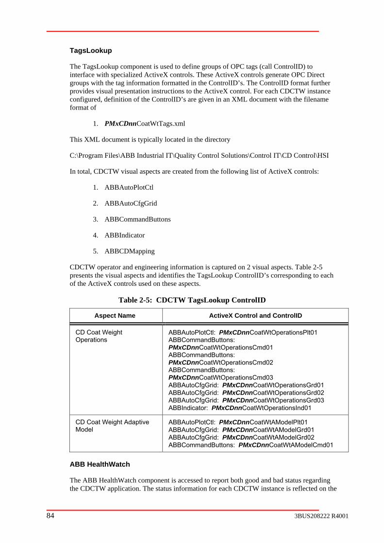
TagsLook
The TagsLookup component is used to define groups of OPC tags (call ControlID) to interfac Direct groups with the tag information formatted in the ControlID’s. The ControlID format further provides vis ce configured, ent with the filename format of
1. PMxCDnnCoatWtTags.xml
This XML document is typically located in the directory
C:\Program Files\ABB Industrial IT\Quality Control Solutions\Control IT\CD Control\HSI
In total, CDCTW visual aspects are created from the following list of ActiveX controls:
1. ABBAutoPlotCtl
2. ABBAutoCfgGrid
3. ABBCommandButtons
4. ABBIndicator
5. ABBCDMapping
CDCTW operator and engineering information is captured on 2 visual aspects. Table 2-5 presents the visual aspects and identifies the TagsLookup ControlID’s corresponding to each of the ActiveX controls used on these aspects.
Table 2-5: CDCTW TagsLookup ControlID
Aspect Name ActiveX Control and ControlID
up
e with specialized ActiveX controls. These ActiveX controls generate OPC
ual presentation instructions to the ActiveX control. For each CDCTW instandefinition of the ControlID’s are given in an XML docum
CD Coat Weight Operations
ABBAutoPlotCtl: PMxCDnnCoatWtOperationsPlt01 ABBCommandButtons:
PMxCDnnCoatWtOperationsCmd02 mandButtons: nCoatWtOperationsCmd03
ABBIndicator: PMxCDnnCoatWtOperationsInd01
PMxCDnnCoatWtOperationsCmd01 ABBCommandButtons:
ABBComPMxCDnABBAutoCfgGrid: PMxCDnnCoatWtOperationsGrd01 ABBAutoCfgGrid: PMxCDnnCoatWtOperationsGrd02 ABBAutoCfgGrid: PMxCDnnCoatWtOperationsGrd03
CD CModel
oat Weight Adaptive ABBAutoPlotCtl: PMxCDnnCoatWtAModelPlt01 ABBAutoCfgGrid: PMxCDnnCoatWtAModelGrd01 ABBAutoCfgGrid: PMxCDnnCoatWtAModelGrd02 ABBCommandButtons: PMxCDnnCoatWtAModelCmd01
ABB Heal
The ABB HealthWatch component is accessed to report both good and bad status regarding the CDCTW application. The status information for each CDCTW instance is reflected on the
thWatch
84 3BUS208222 R4001

PPA Status Report Viewer by a symbol and text messages. CDCTW exposes the following status information to the ABB HealthWatch component:
1. Application Heartbeat – a value generated by CDCTW that is periodically
2. pplication License Error – a valid license could not be obtained for the CDCTW
3. PC Error – tag publishing or connection to the OPC server could not be
4.
5. d time period for the connection to the
2.10.3 Configuration
ion
he job order configuration tool is used to configure all the necessary XML documents for
configured igure 2-13, an example of the “CD Control” tab is
given with “CD Coat Weight” shown as one of the possible “CD Type” selections.
incremented by one
Ainstance
Oestablished
Transporter Watchdog Error – OPC Transporter service did not detect a heartbeatsignal from the corresponding CD control instance in the allotted time period
Transporter Update Error – CDCTW did not receive a new watchdog update fromthe OPC Transporter service in the allottecorresponding CD control instance
6. Application Startup Error – CDCTW could not be started up due to any of the above error conditions or because of a bad CDCTW master configuration XML file
Required Job Order Informat
TCDCTW. Configuration of CDCTW is determined by selection of the “CD Type”, on the“CD Control” tab. If “CD Coat Weight” is select for “CD Type”, then CDCTW is for that specific CD control instance. In F
Figure 2-13: CD control job order configuration tab with “CD Coat Weight” as an option for the “CD Type”
3BUS208222 R4001 85
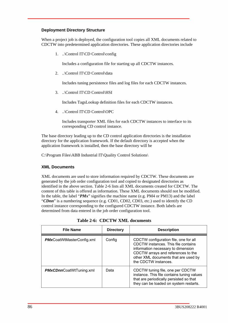
Deploy ture
When a nfiguration tool copies all XML documents related to CDCTW into predetermined application directories. These application directories include
1. ..\Control IT\CD Control\config
Includes a configuration file for starting up all CDCTW instances.
2. ..\Control IT\CD Control\data
g files for each CDCTW instances.
IT\CD Control\HSI
TW instances to interface to its
The base directory leading up to the CD control application directories is the installation
ns\
XML D
XML documents are used to store information required by CDCTW. These documents are generateidentified in ments created for CDCTW. The content of this table is offered as informIn the ta , el “CDnn” is a g sequence (e.g. CD01, CD02, CD03, etc.) used to identify the CD control instance corresponding to the configured CDCTW instance. Both labels are
d in the job order configuration tool.
ment Directory Struc
project job is deployed, the co
Includes tuning persistence files and lo
3. ..\Control
Includes TagsLookup definition files for each CDCTW instances.
4. ..\Control IT\CD Control\OPC
Includes transporter XML files for each CDCcorresponding CD control instance.
directory for the application framework. If the default directory is accepted when the application framework is installed, then the base directory will be
C:\Program Files\ABB Industrial IT\Quality Control Solutio
ocuments
d by the job order configuration tool and copied to designated directories as the above section. Table 2-6 lists all XML docu
ation. These XML documents should not be modified. ble the label “PMx” signifies the machine name (e.g. PM4 or PM13) and the lab
numberin
determined from data entere
Table 2-6: CDCTW XML documents
File Name Directory Description
PMxCoatWtMasterConfig.xml Config CDCTW configuration file, one for all CDCTW instances. This file contains information necessary to dimension CDCTW arrays and references to the
d by other XML documents that are usethe CDCTW instances.
PMxCDnnCoatWtTuning.xml Data CDCTW tuning file, one per CDCTinstance. This file contains tuning va
W lues
that are periodically persisted so that starts. they can be loaded on system re
86 3BUS208222 R4001

File Name Directory Description
PMxCDnnCoatWtAlarms.xml Data CDCTW alarms and events, one per CDCTW instance. At this time, no OPC published alarms and events are defined; therefore, this file is presently
tion alarms or ploaded ecific
CDCTW OPC tag.
empty. To generate applicaevents, PPA alarm and event ushould be configured for the sp
P HSI HSI TagsLookup tag definition file, one per CDCTW instance. This file contains
t the visual aspects created for CDCTW.
MxCDnnCoatWtTags.xml
all the OPC tags (organized as ControlID) necessary to suppor
PMxCDnnCoatWtXPort.xml OPC Transporter file to communicate betweCDCTW and its corresponding CD
en
control instance, one per CDCTW instance.
PMxCDnnCoatWtGDXPort.xml OPC Transporter file to communicate between CDCTW and grade data, one per CDCTW instance.
2.10.4
ups
CD
ataInput
CD control to CDCTW.
tput
rom CDCTW to CD control.
Grade Data
is
PMxCDnnCoatWtGDXPort.xml
Interface to Dependent Application
Data transfer between CDCTW and its corresponding CD control and grade data is achieved entirely by OPC transporters. The following sections identify the specific transporter grocreated by the job order configuration.
Control
The transporter XML document created for transferring CDCTW data with CD control is PMxCDnnCoatWtXPort.xml
This transporter document contains bi-directional transporter groups. The transporter groups contained within and their function are as follows:
1. PMxCDnnCoatWtD Transports data from
2. PMxCDnnCoatWtDataOu Transports data f
The transporter XML document created for transferring grade data information to CDCTW
3BUS208222 R4001 87

The transporter groups contained within and thei
DnnCoatWtGra
Transports data from g
2.10.5 Verify Configuration and O
QC Server Node
After the job order configuration has been deplco DCTW by ug Client. Figure 2-14 gives an exampstartup of the CDCTW applicationgenerate the following messages in
1. “CDCoatControl: CCDCTWSupervisor: Begi
This message is displasupervisor class and p
2. “CDCoatControl: CCD
essage is displa se ng was successf
3. “CDCoatControl: CCD This message is displayed for each CDCTW instance, indicating creation of a
t.
4. “CDCoatControl: CCDCTWSupervisor: Begin initializing CDnn.” This message is displayed for each CDCTW instance, indicating internal
rays and tuning value.
CTW instance, indicating successful startup of the CDCTW instance.
r function are as follows:
1. PMxC
deData
rade data to CDCTW.
peration
oyed and the installation procedure has been ABB QCS Service can be monitored in the ABB Deble of the ABB Debug Client with messages related to
. In the client window, a successful startup of CDCTW will sequence:
nning startup of system. Config file:
mpleted, startup of C
\\…”
yed as a result of ABB QCS Service launching the assing it the CDCTW configuration file.
CTWSupervisor: Valid license obtained.”
This mchecki
yed for each CDCTW instance, indicating that licenul.
CTWSupervisor: Begin creating new object.”
CDCTW objec
initialization of ar
5. “CDCoatControl: CCDCTWSupervisor: CDnn started successfully.” This message is displayed for each CD
88 3BUS208222 R4001

Figure 2-14: ABB Debug Client for startup of CDCTW
Process Portal Functional Structure
After the job order configuration has been deployed and the installation procedure has been completed the following items can be used to verify that PPA configuration for CDCTW is
k the System Status Viewer display on the main QCS ty Control”. The CDCTW features will appear as a
shown configured with CDCTW.
complete.
1. Using Plant Explorer, checobject “Industrial IT Qualichild node to its corresponding CD control instance. The CDCTW features should all have a green circle in the “Status” column. Only the CDCTW features configured should be displayed. In Figure 2-15, “CD Top Coat Weight” is as the CD control instance that is
3BUS208222 R4001 89
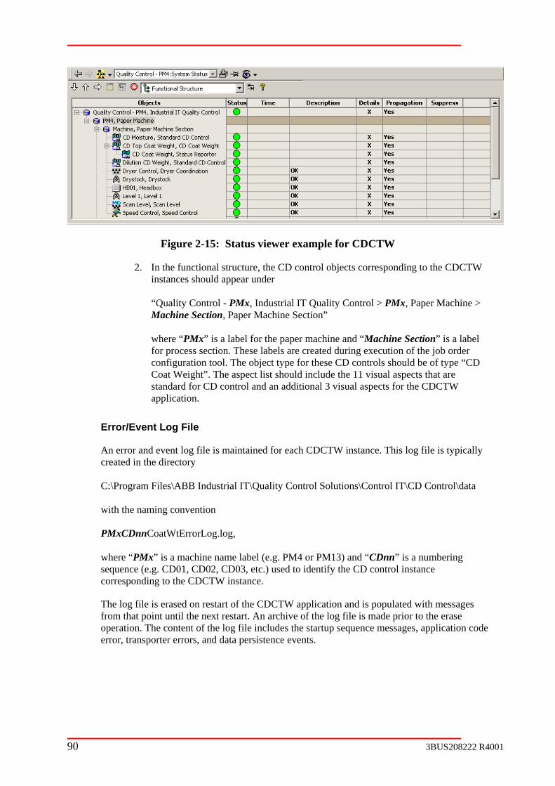
Figure 2-15: Status viewer example for CDCTW
2. In the functional structure, the CD control objects corresponding to the CDCTW instances should appear under “Quality Control - PMx, Industrial IT Quality Control > PMx, Paper Machine >Machine Section, Paper Machine Section
”
where “PM Machine Section” is a label for process section. These labels are created during execution of the job order
on tool. The for these CD controls should be of type “CD Coat Weight”. The aspect list should include the 11 visual aspects that are
ontr additioapplication.
Error/Event Log File
An error and event log file is maintained for each Ccreated in the directory C:\Program Files\ABB Industrial IT\Quality Control Solutions\Control IT\CD Control\data with the nam PMxCDnnCoatWtErrorLog.log, where “PMx” is a machine name label (e.g. PM4 osequence (e.g. CD01, CD02, CD03, etc.) used to idcorresponding to the CDCTW instance.
The log file is erased on restart of the CDCTW appfrom that point until the next restart. An archive ofoperation. The content of the log file includes the startup sequence messages, application code er data p nce event
x” is a label for the paper machine and “
configurati object type
standard for CD c ol and an nal 3 visual aspects for the CDCTW
DCTW instance. This log file is typically
ing convention
r PM13) and “CDnn” is a numbering entify the CD control instance
lication and is populated with messages the log file is made prior to the erase
ror, transporter errors, and ersiste s.
90 3BUS208222 R4001

ol
2.11.1
ability Control (LVC) is a supervising application for CD control. LVC is designed optimize the CD control mapping and the CD control setpoint smoothness to gain
performance. When applied, LVC is associated with a specific CD control package. Data communication between CD control and LVC are transferred via
The LVC application is dependent on the following ABB QCS Application Framework to start up and to expose its OPC data to other ABB QCS applications:
1. QC Object Server
2.
3.
kup
2.11.2
ABB Q sup. The following entries are added to the startup.xml document by the job order configuratio
<component <progID>ABBLVControl.CLVCSupervisor</progID> <param argID="ConfigFile">\\server_name\Paper Quality Control\Control IT\ am> </compo
In the aboveand “PMx” ine label assigned in the job order configuration.
The main roll of ABB QCS Service includes the following:
1. ass the configuration file corresponding to the “ConfigFile” parameter and
2. artup of the QC Object Server so that the LVC application can publish its OPC tags.
2.11 Local Variability (LV) Contr
Overview
Local Varitoimproved profile variability
the OPC Transporter service. The LVC application and its corresponding CD control packageare deployed in the same ABB QCS Server.
ABB QCS Service
OPC Transporter service
4. OPC Publishing
5. TagsLoo
6. ABB Health Watch
Application Framework Dependencies
ABB QCS Service
CS ervice is used to launch the LVC application when the server machine is started
n tool to schedule startup of the LVC application:
class="PCLVControls" ID="PCLVControl1">
CD Control\Config\PMxLVCMasterConfig.xml</parnent>
code example, the “server_name” is the machine name of the ABB QCS Server is the paper mach
Plaunch the LVC class “CLVCSupervisor”.
Notify the LVC application of successful st
3. Request termination of the LVC application when the ABB QCS Service is stopped.
3BUS208222 R4001 91
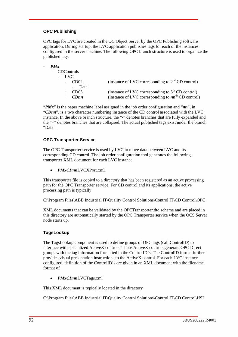
OPC Publi
OPC tags for LVC are created in the QC Object Server by the OPC Publishing software applicat the instances configured in the server machine. The following OPC branch structure is used to organize the published ta
- PMx - CDControls - LVC - CD control) - Data
e of LVC corresponding to 5th CD control) e of LVC corresponding to nnth CD control)
C the above branch structure, the “-” denotes branches that are fully expanded and
the “+” “Data”.
OPC Tran
The OPC Tcorresponding CD control. The job order configuration tool generates the following transporter XML document for each LVC instance:
• PMxCDnnLVCXPort.xml
This transporter file is copied to a directory that has been registered as an active processing path for the OPC Transporter service. For CD control and its applications, the active processing path is typically
C:\Program Files\ABB Industrial IT\Quality Control Solutions\Control IT\CD Control\OPC
XML documents that can be validated by the OPCTransporter.dtd scheme and are placed in this directory are automatically started by the OPC Transporter service when the QCS Server node starts up.
TagsLookup
The Tag ointerface with specialized ActiveX controls. These ActiveX controls generate OPC Direct groups withprovides visconfigured, definition of the ControlID’s are ent with the filename format of
• PM
This XML d
C:\Program Files\ABB Industrial IT\Quality Control Solutions\Control IT\CD Control\HSI
shing
ion. During startup, the LVC application publishes tags for each of
gs
CD02 (instance of LVC corresponding to 2nd
+ CD05 (instanc + CDnn (instanc
“PMx” is the paper machine label assigned in the job order configuration and “nn”, in “CDnn”, is a two character numbering instance of the CD control associated with the LVinstance. In
denotes branches that are collapsed. The actual published tags exist under the branch
sporter Service
ransporter service is used by LVC to move data between LVC and its
sL okup component is used to define groups of OPC tags (call ControlID) to
the tag information formatted in the ControlID’s. The ControlID format further ual presentation instructions to the ActiveX control. For each LVC instance
given in an XML docum
xCDnnLVCTags.xml
ocument is typically located in the directory
92 3BUS208222 R4001

cts are created from the following list of ActiveX controls:
2. ABBAutoCfgGrid
3. ABBCommandButtons
4. ABBIndicator
5. ABBCDMapping
sents
In total, LVC visual aspe
1. ABBAutoPlotCtl
LVC operator and engineering information is captured on 6 visual aspects. Table 2-7 prethe visual aspects and identifies the TagsLookup ControlID’s corresponding to each of the ActiveX controls used on these aspects.
Table 2-7: LVC TagsLookup ControlID
Aspect Name ActiveX Control and ControlID
LVC Overview ABBAutoPlotCtl: PMxCDnnLVCOverviewPlt01 ABBIndicator: PMxCDnnLVCOverviewInd01 ABBCommandButtons: PMxCDnnLVCOverviewCmd01 ABBAutoCfgGrid: PMxCDnnLVCOverviewGrd01 ABBAutoCfgGrid: PMxCDnnLVCOverviewGrd02
LVC Optimization Curve View
ABBAutoPlotCtl: PMxCDnnLVCCurveViewPlt01 ABBAutoCfgGrid: PMxCDnnLVCCurveViewGrd01 ABBAutoCfgGrid: PMxCDnnLVCCurveViewGrd02
LVC Monitor Setup ABBAutoPlotCtl: PMxCDnnLVCMonitorSetupPlt01 ABBIndicator: PMxCDnnLVCMonitorSetupInd01 ABBCommandButtons: PMxCDnnLVCMonitorSetupCmd01
rd01 02
ABBAutoCfgGrid: PMxCDnnLVCMonitorSetupGABBAutoCfgGrid: PMxCDnnLVCMonitorSetupGrdABBAutoCfgGrid: PMxCDnnLVCMonitorSetupGrd03
LVC Optimization Setup ABBIndicator: PMxCDnnLVCOptSetupInd01 ABBCommandButtons: PMxCDnnLVCOptSetupCmd02 ABBAutoCfgGrid: PMxCDnnLVCOptSetupGrd01 ABBAutoCfgGrid: PMxCDnnLVCOptSetupGrd02 ABBAutoCfgGrid: PMxCDnnLVCOptSetupGrd03 ABBAutoCfgGrid: PMxCDnnLVCOptSetupGrd04
ABBAutoCfgGrid: PMxCDnnLVCOptSetupGrd05 ABBAutoCfgGrid: PMxCDnnLVCOptSetupGrd06
LVC PSave/Res
ABBAutoPlotCtl: PMxCDnnLVCParamSavePlt01 ABBAutoCfgGrid: PMxCDnnLVCParamSaveGrd01 ABBCommandButtons: PMxCDnnLVCParamSaveCmd01 ABBCommandButtons: PMxCDnnLVCParamSaveCmd02
CommandButtons: PMxCDnnLVCParamSaveCmd03
arameter tore
ABB
LVC M ABBAutoPlotCtl: PMxCDnnLVCMapMismatchPlt01 ABBAutoCfgGrid: PMxCDnnLVCMapMismatchGrd01 ABBCommandButtons: PMxCDnnLVCMapMismatchCmd01
apping Mismatch
3BUS208222 R4001 93

ABB HealthWatch
The ABB HealthWatcthe LVC application. T
h component is accessed to report both good and bad status regarding he status information for each LVC instance is reflected on the PPA
one
d not be obtained for the LVC
t nal from the corresponding CD control instance in the allotted time period
a new watchdog update from the
2.11.3 Config a
The job order configuration tool is used to configure all the necessary XML documents for
tance “CD Control” tab is given with the “LVC”
Status Report Viewer by a symbol and text messages. LVC exposes the following statusinformation to the ABB HealthWatch component:
1. Application Heartbeat – a value generated by LVC that is periodically incremented by
2. Application License Error – a valid license coulinstance
3. OPC Error – tag publishing or connection to the OPC server could not be established
4. Transporter Watchdog Error – OPC Transporter service did not detect a heartbeasig
5. Transporter Update Error – LVC did not receiveOPC Transporter service in the allotted time period for the connection to the corresponding CD control instance
6. Application Startup Error – LVC could not be started up due to any of the aboveerror conditions or because of a bad LVC master configuration XML file
ur tion
Required Job Order Information
LVC. Configuration of LVC is controlled by a checkbox under the column label “LVC”, on the “CD Control” tab. By checking this checkbox, LVC is configured for that specific CD control instance. The “LVC” checkbox is left unchecked if LVC is not desired for an insof CD control. In Figure 2-16, an example of thecheckbox highlighted.
Figure 2-16: CD control job order configuration tab with LVC checkbox
94 3BUS208222 R4001

cture
fig
r starting up all LVC instances.
• ..\Control IT\CD Control\HSI
Includes TagsLookup definition files for each LVC instances.
Includes transporter XML files for each LVC instances to interface to its ng CD control instance.
n
XML D
XML do information required by LVC. These documents are generated by the job order configuration tool and copied to designated directories as identified in the above section. Table 2-8 lists all XML documents created for LVC. The content of this table is offered as information. These XML documents should not be modified. In the ta signifies the machine name (e.g. PM4 or PM13) and the label
File Name Directory
Deployment Directory Stru
When a project job is deployed, the configuration tool copies all XML documents related toLVC into predetermined application directories. These application directories include
• ..\Control IT\CD Control\con
Includes a configuration file fo
• ..\Control IT\CD Control\data Includes tuning persistence files and log files for each LVC instances.
• ..\Control IT\CD Control\OPC
correspondi
The base directory leading up to the CD control application directories is the installatiodirectory for the application framework. If the default directory is accepted when the application framework is installed, then the base directory will be
C:\Program Files\ABB Industrial IT\Quality Control Solutions\
ocuments
cuments are used to store
ble, the label “PMx” “CDnn” is a numbering sequence (e.g. CD01, CD02, CD03, etc.) used to identify the CD control instance corresponding to the configured LVC instance. Both labels are determinedfrom data entered in the job order configuration tool.
Table 2-8: LVC XML documents
Description
PMx Config n d s that
LVCMasterConfig.xml LVC configuration file, one for all LVC instances. This file contains informationecessary to dimension LVC arrays anreferences to the other XML documentare used by the LVC instances.
PMxCDnnLVCTuning.xml Data LVC tuning file, one per LVC instance. This file contains tuning values that are periodically persisted so that they can be loaded on system restarts.
3BUS208222 R4001 95

File Name Directory Description
PMxCDnnLVCAlarms.xml Data LVC alarms and events, one per LVC instance. At this time, no OPC published
,
d
alarms and events are defined; thereforethis file is presently empty. To generate application alarms or events, PPA alarm and event uploaded should be configurefor the specific LVC OPC tag.
PMxCDn inition file, one per LVC instance. This file contains all the OPC
support the visual aspects created for LVC.
nLVCTags.xml HSI HSI TagsLookup tag def
tags (organized as ControlID) necessary to
PMxCDnnLVC to communicate tween onding CD c ntrol C instance.
XPort.xml OPC Transporter file LVC and its correspinstance, one per LV
beo
2.11.4 Interface to Dependent Application
Data transfer between LVC and its corresponding CD control is achieved entirely by OPC transporters. The following identifies the specific transporter groups created by the job order configuration. T tr created for transferring LVC data with CD control is PMxCDnnLVC o
This transporter oc ional transporter groups. The transporter groups contained within and their function are as follows:
• PM D Tran o LVC.
• PM Tran
2.11.5 Config
rver No
After the job ord n procedure has been completed, startup of LVC by onitored in the ABB Debug Client.
2-17 give related to st up of the LVC applica C will generate the following messa
1. “LVControl: CLVCSupervisor: Beginning startup of LV Control system. Config file: \\…” This message is displayed as a result of ABB QCS Service launching the
he ansporter XML document
XP rt.xml
d ument contains bi-direct
xC nnLVCDataInput
sp rts data from CD control to
xCDnnLVCDataOutput
sports data from LVC to CD control.
Verify uration and Operation
QC Se de
er configuration has been deployed and the installatio ABB QCS Service can be m
Figure s an example of the ABB Debug Client with messages tion. In the client window, a successful startup of LVges in sequence:
art
96 3BUS208222 R4001

supervisor class and passing it the LVC configuration file.
“LVControl: CLVCSupervisor: Valid LV control license obtained.” This m stance, indicating that license checking was succ s
3. “LVControl: CLVCSupervisor: Begin creating new LVControl object.” This creation VC obje
4. “LVControl: CLVCSupervisor: Begin initializing LVCnn.” This message is displayed for each LVC instance, indicating internal initialization of arrays and tuning value.
5. “LVControl: CLVCSupervisor: LVCnn started successfully.” This message is displayed for each LVC instance, indicating successful startup of the LVC instance.
2.
essage is displayed for each LVC ines ful.
message is displayed for each LVC instance, indicatingct.
of a L
3BUS208222 R4001 97
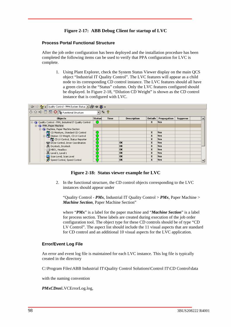
Figure 2-17: ABB Debug
ortal Functional Structure
Client for startup of LVC
Process P
After the job order configuration has been deployed and the installation procedure has been completed tcomplete.
in QCS
res configured should is shown as the CD control
he following items can be used to verify that PPA configuration for LVC is
1. Using Plant Explorer, check the System Status Viewer display on the maobject “Industrial IT Quality Control”. The LVC features will appear as a child node to its corresponding CD control instance. The LVC features should all have a green circle in the “Status” column. Only the LVC featube displayed. In Figure 2-18, “Dilution CD Weight”instance that is configured with LVC.
Figure 2-18: Status viewer example for LVC
2 ctional str D control objects co the LVC
PMx dustrial IMachine Section, Paper Machine S where “PMx” is a label for the papefor process section. These labels are created during execution of the job order
pe for thThe a ist should rd
for CD control and an additional 10
Error/Event Log File
An error and event log file is maintained for eaccreated in the directory C:\Program Files\ABB Industrial IT\Quality Con with the naming convention PMxCDnnLVCErrorLog.log,
. In the funinstances should appear under
ucture, the C rresponding to
“Quality Control - , In T Quality Control > PMx, Paper Machine >
ection”
r machine and “Machine Section” is a label
configuration tool. The object tyLV Control”.
ese CD controls should be of type “CD include the 11 visual aspects that are standa visual aspects for the LVC application.
spect l
h LVC instance. This log file is typically
trol Solutions\Control IT\CD Control\data
98 3BUS208222 R4001

where “PMx” is a machine name label (e.g. PM4 or PM13) and “CDnn” is a numbering sequence (e.g. CD01, CD02, CD03, etc.) used to identify the CD control instance co C instan
The log file is erased on restart of the LVC applithat point until the next restart. An archive of the n. The content of the log file includes the startup se e error, transporter errors, and data persistence events.
2.12 CD Actuator Agent
2.12.1 O
CD control is an application designed to correct g control actions to CD actuators (e.g. headbox slice, water spray, and infrared dryer). In order to fu rol re the existeits intended tasks. The CD actuator agent is des an interface to an existing CD actuator.
The CD actuator agent is designed as a software interface to an actuator system for de S Se he actuatointerface to handle data flow via an OPC Transpthe integrated ABB QCS solution, this requiremXML documents needed by the OPC Transporte for passing data back and forth. The communication to the actuator sub-system itself utilizes standard networking protocols. The
pe of actuator chosen in the configuration
1. QC Object Server
6.
2.12.2 Application Framework Dependencies
ABB QCS Service
ABB QCS smachine, in the startup. actuator agent application:
rresponding to the LV ce.
cation and is populated with messages from log file is made prior to the erase operatioquence messages, application cod
verview
variations in the CD by applyin
nction correctly, the cont quires nce of a CD actuator sub-system to perform igned to provide the CD control system with
ployment in an ABB QC rver. T r agent is implemented with an OPC orter service to the CD control system. For ent is fulfilled to the extent of creating the r service
particular protocol used is determined by the tysession.
The CD actuator agent application is dependent on the following ABB QCS Application Framework to start up and to expose its OPC data to other ABB QCS applications:
2. ABB QCS Service
3. OPC Transporter service
4. OPC Publishing
5. TagsLookup
ABB Health Watch
ervice is used to launch the CD actuator agent application when the server which CD actuator agent exists, is started up. The following entries are added toxml document by the job order configuration tool to schedule startup of the CD
3BUS208222 R4001 99

<component class=" PCCDActuators " ID=" PCD <progID> ABBCDActInterface.CAISuperviso
Actuator1"> r </progID>
<param argID="ConfigFile">\\server_name\Paper Quality Control\Profile IT \CD Actuator\config\PMxActMasterConfig.xml</param>
rrorFile">ErrorLog.log</param>
,
CD actuator agent class “CAISupervisor”.
2. Object .
3. Request termination of the CD actuator agent application when the ABB QCS
OPC Publ
OPC tags for the CD actuator agent are created in the QC Object Server by the OPC Publish s publishes tags for anch structure is
- PMx - CDActuators ) of CD actuator agent)
where ““Actnn
In the abovedenotes branlabeled “Da ags that are tuni the value of zero. The tag quality remains “uncertain” until it is written to either by an internal write from the
OPC Trans
For some actuators, the OPC Transporter service is used by the CD actuator agent to move data between the actuator agent application and tags created in the Job Order Configuration Tool to com following transporter XML documents:
•
<param argID="E</component>
In the above code example, the “server_name” is the machine name of the ABB QCS Serverin which CD control exists, and “PMx” is the paper machine label assigned in the job order configuration.
The main roll of ABB QCS Service includes the following:
1. Pass the configuration file corresponding to the “ConfigFile” parameter and launch the
Notify the CD actuator agent application of successful startup of the QCServer so that the CD actuator agent application can publish its OPC tags
Service is stopped.
ishing
ing oftware application. During startup, the CD actuator agent application each of the instances present in the server machine. The following OPC br
used to organize the published tags
- Instances - Act01 (1st instance of CD actuator agent)
+ Data (Data tags for in the CD actuator agent application+ Act02 (2nd instance of CD actuator agent) + Actnn (n-th instance
PMx” is the paper machine label assigned in the job order configuration and “nn”, in ”, is a two character numbering instance of the CD actuator agent.
branch structure, the “-” denotes branches that are fully expanded and the “+” ches that are collapsed. The actual published tags exist under the branches
ta”. At startup, the tags under the “Data” branch are created and initialized. Tng parameters are set to persisted values. All other tags are initialized to
CD actuator agent or an external write by a client application.
porter Service
municate with those actuators. The Job Order Configuration Tool generates the
PMxActnnDeviceXPort.xml
100 3BUS208222 R4001

Additional i he required tra istered as an active processing path for the OPC Transporter service. For the CD actuator agent, the active processing path is typically
C:\Program Control Solutions\Profile IT\CD Actuator\OPC
XML docum schema and are placed in this directory are automatically started by the OPC Transporter service when the QCS Server
ode starts up.
TagsLookup
The ) to interface with specialized ActiveX controls. These ActiveX controls generate OPC Direct
the ControlID’s. The ControlID format further provides visual presentation instructions to the ActiveX control. The CD actuator agent visual
utoPlotCtl
6.
7. ABBIndicator
CD actuator agent operator and engineering information is captured on one visual aspect. Table 2-9 presents a thumbnail of this aspect and identifies the TagsLookup ControlIDs corresponding to each of the ActiveX controls used on this aspect.
Table 2-9: CD actuator agent TagsLookup ControlID
Aspect Name ActiveX Control and ControlID
nformation about these XML documents is provided in section 2.12.3. Tnsporter files are copied to a directory that has been reg
Files\ABB Industrial IT\Quality
ents that can be validated by the OPCTransporter.dtd
n
TagsLookup component is used to define groups of OPC tags (call ControlID
groups with the tag information formatted in
aspect is created with the use of four ActiveX controls:
4. ABBA
5. ABBAutoCfgGrid
ABBCommandButtons
Actuator Overview
1. ABBAutoPlotCtl: PmxActnnOperPlt01 perGrd01 perGrd02
d01
2. ABBAutoCfgGrid: PmxActnnO3. ABBAutoCfgGrid: PmxActnnO4. ABBIndicator: PmxActnnOperInd01 5. ABBCommandButtons: PmxActnnOperCm
2.12.3 Configura
Required J
The job ord ts for the CD acturequired for each CD actuator agent instance being configured. In Figure 2-19, the “Figure Reference” numbers shown in Table 2-10 are identified as callouts, outlined with a box.
Table 2-10: CD actuator agent job order information
tion
ob Order Information
er configuration tool is used to configure all the necessary XML documenator agent. In order to achieve this task, the information presented Table 2-10 is
3BUS208222 R4001 101

Configuration Labels
Description Figure Reference
Actuator Type The actuator type field defines the type of actuator for which the CD actuator agent is being configured. The type is selected from an option list that includes the following items:
• Smart Weight Profiler • Smart Calendar Profiler • CoatWeight Profiler • Dilution Profiler • Smart CoatWeight Profiler • Smart Consistency Profiler • Accuray Serial Weight • Accuray Serial Caliper • Accuray Serial Moisture • Impact IR serial • Impact Thermajet Serial • Impact Stepper Motor Serial
• MX 200/100 Serial Caltrol 100 Serial Aquatrol
• Serial Steambox
rchase order. The configured CD actuator agent types will be checked for valid licenses.
1
• MX 200/100 Serial Thermatrol • MX 200/100 Serial Dynatrol
• MX 200/VIB
The type should be chosen in accordance to the features appearing in the pu
Descrir agent instance. This description will be
e functional structure of PPA.
ption The description field is a user-defined entry for identifying the CD actuatocaptured in th
2
Num ones field indicates the number of zones in the specified CD actuator. This number is used to configure
3 Zones The num z
data points in the CD actuator agent.
IP Address Actuators that support communications via TCP/IP require 4 an actuator IP Address. A valid IP Address format is in dotted octet form: 171.64.20.1. Serial communications devices do not require an IP Address. For serial devices the default value is sufficient.
ThirType
• Voith OPC Link • AC800 Direct I/O Link • AC800 Modbus Link
d-Party Link
For third-party actuator support, select the system type from the drop-down list:
• None (Default)
N/A
Third-Party Link Node
For third-party actuators enter the node (PC machine name) where the third-party software will run.
N/A
102 3BUS208222 R4001
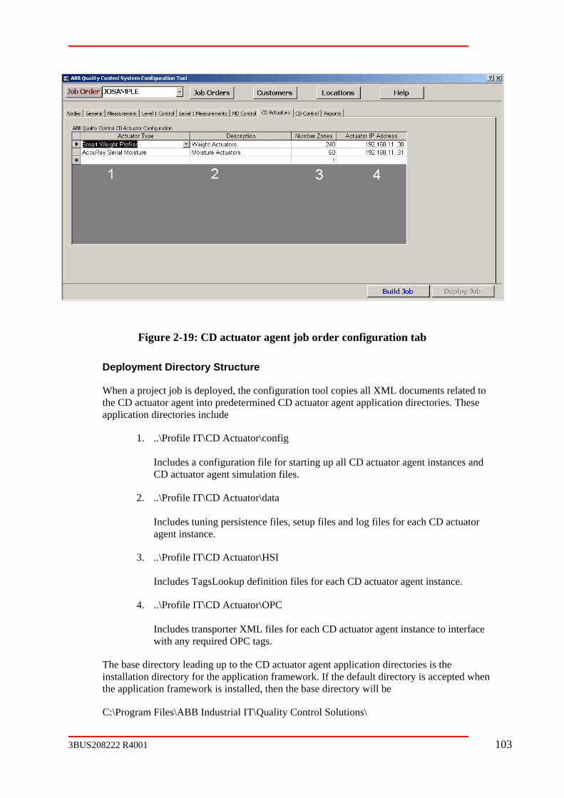
Figure 2-19: CD actuator agent job order configuration tab
Deployment Directory Structure
When a project job is deployed, the configuration tool copies all XML documents related to the CD actuator agent into predetermined CD actuator agent application directories. These application directories include
1. ..\Profile IT\CD Actuator\config Includes a configuration file for starting up all CD actuator agent instances and CD actuator agent simulation files.
2. ..\Profile IT\CD Actuator\data
tuning persistence files, setup files and log files for each CD actuator
each CD actuator agent instance.
Includes transporter XML files for each CD actuator agent instance to interface
tor agent application directories is the
Includesagent instance.
3. ..\Profile IT\CD Actuator\HSI Includes TagsLookup definition files for
4. ..\Profile IT\CD Actuator\OPC
with any required OPC tags.
The base directory leading up to the CD actuainstallation directory for the application framework. If the default directory is accepted when the application framework is installed, then the base directory will be
C:\Program Files\ABB Industrial IT\Quality Control Solutions\
3BUS208222 R4001 103

The Job Order Configuration tool will produce all OPC tags associated with the actuator for the QCS OPC Server in the ..\CommunicateIT\Dictionary directory.
XML Documents
XML documents are used to store information required by CD actuator agent. These on tool and copied to designated
directories as identified in the above section. Table 2-11 lists all XML documents related to the CD actuator agen ation. These XML documents should not be modified. In the table, the label “PMx” signifies the machine name (e.g. PM4 or PM13) and the label “ACTnn” is a numbering sequence (e.g. Act01, Act02, Act03, etc.) used to identify the CD actuator agent instances. Both labels are entered during execution of the job order configuration tool.
Table 2-11: CD actuator agent XML documents
File Name Directory Description
documents are generated by the job order configurati
t. The content of this table is offered as inform
PMxActMasterConfig.xml
Config CD actuator agent configuration file, one for all CD actuator agent instances. This file contains information necessary to dimension arrays and references to the other XML documents that are used by the CD actuator agent instances.
PMxActnnConfig.xml Data CD actuator agent tuning file, one per CD actuator agent instance. This file contains
t are periodically persisted be loaded on system restarts.
tuning values thaso that they can
PMxActnnAlarms.xml Data CD actuator agent alarms and events, one per CD actuator agent instance. This file
vents. contains OPC published alarms and e
PmxActServer.xml HSI HSI TagsLookup alias file, one for all actuator agent instances. This file con
CD tains
branch names of all CD control instances.
aliases for the QC Object Server name and the OPC
PMxActnnTags.xml CD actuator agent instance. This file contains all the OPC tags (organized as ControlID) necessary to support the visual aspects created for CD actuator agents.
HSI HSI TagsLookup tag definition file, one per
PMxActnnDeviceXPort.xml
OPC Device data transporter, one per CD actuator agent that interfaces to Job Order Config generated OPC tags for communication to the actuator system.
PmxActnnSimMasterConfig.xml
Config CD actuator agent simulation configuration file, one for each CD actuator agent instance. This file contains parameters for defining the actuator system in simulation.
104 3BUS208222 R4001

File Name Directory Description
PmxCDnnSimAlarms.xml
Data CD actuator agent simulator tuning file, one per CD actuator agent instance. This file contains tuning values that are periodically persisted so that they can be loaded on system restarts.
PmxCDnnSimConfig.xml
Data CD actuator agent simulator alarms and events, one per CD actuator agent instance. This file contains OPC published alarms and events.
2.12.4
ed er configuration.
PMxActnnDevicetXPort.xml
Transports data from the CD actuator agent to the actuator defined in the Job Order Configuration Tool. Transported data includes new actuator setpoints generated automatically or manually from the CD control.
• PMxACTnnDevice1Input Transports data from the actuator to the CD actuator agent. Transported data includes actuator measurement feedback, bad actuator status, bad measurement feedback status, actuator not moveable status, actuator in local status, actuator request to suspend CD control flag, actuator request to abort CD control flag.
2.12.5
QC Server Node
deployed and the installation procedure has been by ABB QCS Service can be monitored in the
s
AISupervisor: Beginning startup for actuator interface system. Config file: \\…” This message is displayed as result of ABB QCS Service launching the
Interface to Dependent Application
Data transfer between the CD actuator agent and other QCS applications is achieved entirely by OPC transporters. The following sections identify the specific transporter groups creatby the job ord
This transporter document contains bi-directional transporter groups. The transporter groups contained within and their function are as follows:
• PMxACTnnDevice1Output
Verify Configuration and Operation
After the job order configuration has beencompleted, startup of the CD actuator agent ABB Debug Client. Figure 2-20 gives an example of the ABB Debug Client with messagerelated to startup of the CD actuator agent application. In the client window, a successful startup of the CD actuator agent will generate the following messages in sequence:
1. “CABB
3BUS208222 R4001 105

supervisor class and passing it the CD actuator agent configuration file.
2. “CABBAISupervisor: Begin creating new actuator interface object.”
This message is displayed for each CD actuator agent instance, indicating creation of a CD new actuator agent object.
zing actuator interface object ACTnn.”
This message is displayed for each CD actuator agent instance, indicating internal uning values.
5. “CABBAISupervisor: Publishing tags for actuator interface object Actnn “. This message is displayed for each CD actuator agent instance, indicating creation of OPC tags in the QC Object Server. This step of the CD actuator agent startup is postponed until the ABB QCS Service notifies the actuator agent supervisor that the target QC Object Server has successfully started up.
6. “CABBAISupervisor: Checking license for actuator interface object Actnn.” This message is displayed for each CD actuator agent instance, indicating that license is being checked.
7. “CABBAISupervisor: Connecting to OPC Server for actuator interface object Actnn.” This message is displayed for each CD actuator agent instance, indicating that the CD actuator agent application has established a link with the QC Object Server. If a license for the CD actuator agent instance could not be validated, the connection to the QC Object Server is not performed.
visor: Actnn started successfully.”
3. “CABBAISupervisor: Initiali
initialization of arrays and t
4. “CABBAISupervisor: Actuator interface object ACTnn initialized.” This message is displayed for each CD actuator agent instance, indicating completion of internal initialization.
8. “CABBAISuper This message is displayed for each CD actuator agent instance, indicating successful startup of the CD actuator agent instance.
106 3BUS208222 R4001
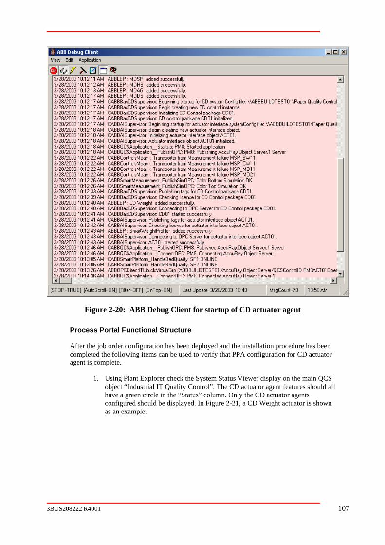
Figure 2-20: ABB Debug Client for startup of CD actuator agent
Process Portal Functional Structure
After the job order configuration has been deployed and the installation procedure has been ompleted the following items can be used to verify that PPA configuration for CD actuator
agent is complete.
lorer check the System Status Viewer display on the main QCS al IT Quality Control”. The CD actuator agent features should all
c
1. Using Plant Expobject “Industrihave a green circle in the “Status” column. Only the CD actuator agents configured should be displayed. In Figure 2-21, a CD Weight actuator is shown as an example.
3BUS208222 R4001 107
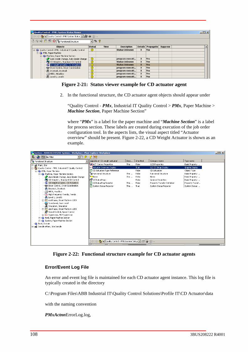
Figure 2-21: Status viewer example for CD actuator agent
2. In the functional structure, the CD actuator agent objects should appear under “Quality Control - PMx, Industrial IT Quality Control > PMx, Paper Machine > Machine Section, Paper Machine Section” where “PMx” is a label for the paper machine and “Machine Section” is a label for process section. These labels are created during execution of the job order configuration tool. In the aspects lists, the visual aspect titled “Actuator overview” should be present. Figure 2-22, a CD Weight Actuator is shown as an example.
Figure 2-22: Functional structure example for CD actuator agents
Error/Event Log File
An error and event log file is maintained for each CD actuator agent instance. This log file is typically created in the directory C:\Program Files\ABB Industrial IT\Quality Control Solutions\Profile IT\CD Actuator\data with the naming convention PMxActnnErrorLog.log,
108 3BUS208222 R4001

where “PMx” is a machine name label (e.g. PM4 or PM13) and “Actnn” is a numbering sequence (e.g. ACT01, ACT02, ACT03, etc.) used to identify the CD control instances.
The log file is erased on restart of the CD actuator agent application and is populated with messages from that point until the next restart. The content of the log file includes the startup sequence messages, application code error, transporter errors, and data persistence events.
If the content of the log file is important for troubleshooting, it is essential to copy the file into a safe location before restarting the CD actuator agent application. As mentioned in the
D actuator agent application.
above paragraph, the log file is erased on restart of the C
3BUS208222 R4001 109

Chapter 3 Troubleshooting
3.1 Qualon
ality Control Diagnostics Aspect is an Aspect of IT
Figure 3-1 Quality Control Diagnostics Aspect in the Functional Structure
ity Control Diagnostics Aspect The Quality Control Diagnostics Aspect provides a central location for accessing commtroubleshooting displays and tools. The Quthe main Industrial Quality Control Object in the Functional Structure.
Figure 3-2 Quality Control Diagnostics Example Display
3.1.1 Configura
Override thAspect links. The Controller Status should link to the AC800M Status Viewer Aspect in the Control Structure and the Nodes Status should link to the System Status Viewer on the All Nodes G
The buttonsuseful fault
tion
is Aspect and edit it to set the Aspect for the Controller Status and Node Status
roup in the Node Administration Structure.
on this Aspect are links to various graphics displays and tools that may contain tracing information.
110 3BUS208222 R4001

3.2 Debug MesThe Debug Message Viewer tool displays debug messages from Quality Control applications. You can launch this tool from the Start Menu or from the Quality Control Diagnostics Aspect.
he message viewer to a file by using the Copy contents to ting the result into Notepad or another text editor.
Figure 3-3 Debug Message Viewer Tool example
sage Viewer
You can save the contents of tClipboard feature and then pas
Key
e following functions. The Toolbar icons perform th
3BUS208222 R4001 111
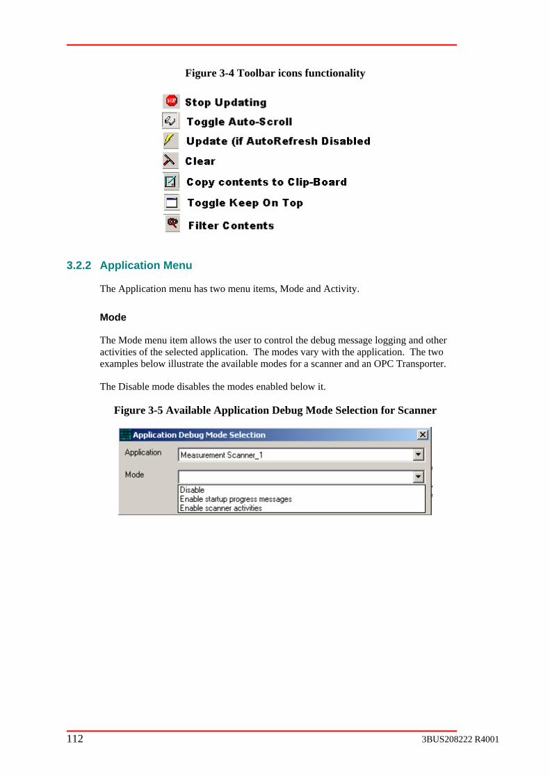
Figure 3-4 Toolbar icons functionality
3.2.2 Application Menu
The Application menu has two menu items, Mode and Activity.
Mode
The Mode menu item allows the user to control the debug message logging and other activities of the selected application. The modes vary with the application. The two examples below illustrate the available modes for a scanner and an OPC Transporter.
The Disable mode disables the modes enabled below it.
Figure 3-5 Available Application Debug Mode Selection for Scanner
112 3BUS208222 R4001

Figure 3-6 Available Application Debug Mode Selection for OPC Transporter
Activity
The Activity menu item allows the user to monitor the status and activity of the selected application. The status properties and activities available vary with the application. The two examples below show the status properties and activities for a measurement and an OPC Transporter.
Figure 3-7 Application Activity status properties for Measurement Basis Weight
The HealthWatch error and warning items indicate an error and / or warning condition for the application if non-zero. The HealthWatch heartbeat should increment periodically.
Figure 3-8 Application Activity status properties for OPC Transporter
Refer to Appendix A – OPC Transporter for information on the Activity fields for OPC Transporters.
3BUS208222 R4001 113
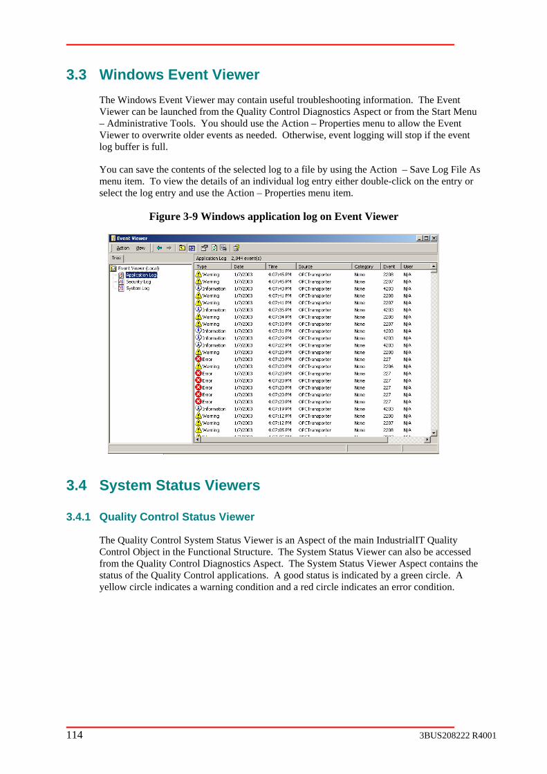
3.3 Windows Event Viewer The Windows Event Viewer may contain useful troubleshooting information. The Event Viewer can be launched from the Quality Control Diagnostics Aspect or from the Start Menu – Administrative Tools. You should use the Action – Properties menu to allow the Event Viewer to overwrite older events as needed. Otherwise, event logging will stop if the event log buffer is full.
You can save the contents of the selected log to a file by using the Action – Save Log File As menu item. To view the details of an individual log entry either double-click on the entry or select the log entry and use the Action – Properties menu item.
Figure 3-9 Windows application log on Event Viewer
3.4 System Status Viewers
3.4.1 Quality Control Status Viewer
The Quality Control System Status Viewer is an Aspect of the main IndustrialIT Quality Control Object in the Functional Structure. The System Status Viewer can also be accessed from the Quality Control Diagnostics Aspect. The System Status Viewer Aspect contains the status of the Quality Control applications. A good status is indicated by a green circle. A yellow circle indicates a warning condition and a red circle indicates an error condition.
114 3BUS208222 R4001

Figure 3-10 Quality Control Status Viewer example
3.4.2 Nodes Status Viewer
The System Status Viewer Aspect of the All Nodes group in the Node Administration Structure displays the status of the Afw Services for the Aspect Server and Connectivity Server nodes.
3.4.3 AC800M Controller Status Viewer
The AC800M Controller System Status Viewer Aspect displays the status of the AC800M applications and I/O.
3.5 License Viewer The ABB QCS License Manager utility allows users to View, Add licenses to and Delete licenses from the QCS.
3BUS208222 R4001 115
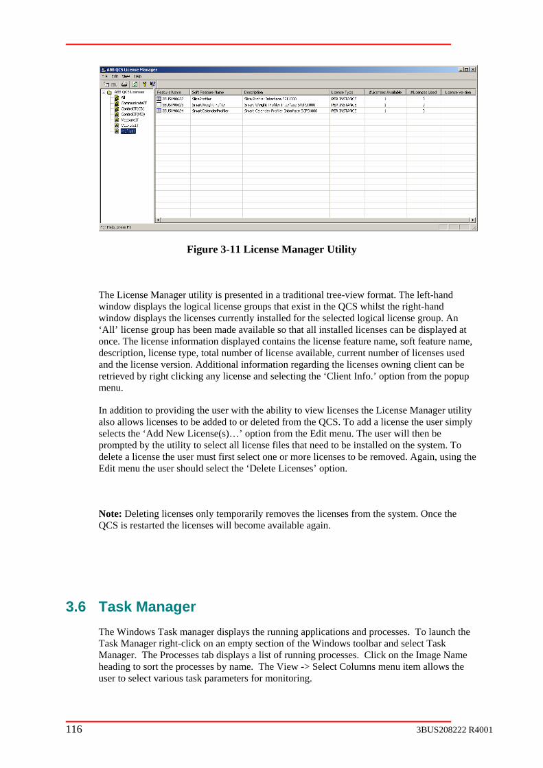
Figure 3-11 License Manager Utility
The License Manager utility is presented in a traditional tree-view format. The left-hand window displays the logical license groups that exist in the QCS whilst the right-hand window displays the licenses currently installed for the selected logical license group. An ‘All’ license group has been made available so that all installed licenses can be displayed at once. The license information displayed contains the license feature name, soft feature name, description, license type, total number of license available, current number of licenses used and the license version. Additional information regarding the licenses owning client can be retrieved by right clicking any license and selecting the ‘Client Info.’ option from the popup menu.
In addition to providing the user with the ability to view licenses the License Manager utility also allows licenses to be added to or deleted from the QCS. To add a license the user simply selects the ‘Add New License(s)…’ option from the Edit menu. The user will then be prompted by the utility to select all license files that need to be installed on the system. To delete a license the user must first select one or more licenses to be removed. Again, using the Edit menu the user should select the ‘Delete Licenses’ option.
Note: Deleting licenses only temporarily removes the licenses from the system. Once the QCS is restarted the licenses will become available again.
3.6 Task Manager The Windows Task manager displays the running applications and processes. To launch the Task Manager right-click on an empty section of the Windows toolbar and select Task Manager. The Processes tab displays a list of running processes. Click on the Image Name heading to sort the processes by name. The View -> Select Columns menu item allows the user to select various task parameters for monitoring.
116 3BUS208222 R4001

troubleshooting Figure 3-12 Windows Task Manager aids in
3.7 OPC Inspector
3.8 This viewer displays all data OPC Direct IT is currently handling. The window is divided into
part displays a list of OPC servers currently connected to by OPC Direct IT. The bottom part displays all data points connected with OPC Direct IT. These lists comprises
OPC Direct IT Viewer
two parts. The top
of all data requested from all OPC Direct IT clients.
3BUS208222 R4001 117

Figure 3-13 OPC Direct IT Viewer
Figure 3-14 OPC Direct IT Viewer Top Area
3.8.1 ctive OPC Server Monitors
ls the OPC servers to test the connection state. OPC Direct IT is one of its IT
e Up, Down, or Poll.
mally pped.
ceived (e.g. network cable cut).
Top Window - A
This window is populated by the ABBOPCMonitor component. This component monitors OPC servers, and notifies its clients when servers are reachable (UP) or not (DOWN). This component polclients, since OPC Direct needs to know when OPC servers go UP and DOWN.
OPC Server – NodeName \ ServerName of an OPC server
3. State – Can b
Up - OPC Server is responding to polls
Down - OPC server is not responding to polls
Poll – OPC server is being polled
Clients – Normally, OPC Direct IT is its only client, and the number is 1.
4. Shut Downs – Number of “ShutDown” events received by OPC Direct IT from the OPC server. OPC servers issue “ShutDown” events when they are forsto
5. Poll Time Out – Number of times OPC Direct IT did not receive poll response from OPC server within the Poll timeout period. This counter increments when communication is lost with OPC server, and no “ShutDown” event was re
118 3BUS208222 R4001
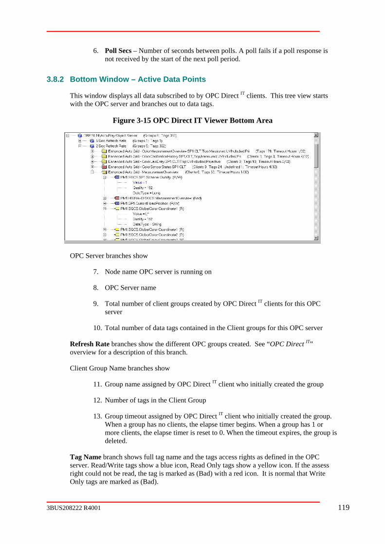
seconds between polls. A poll fails if a poll response is not received by the start of the next poll period.
3.8.2 Active Data Points
This window displays all data subscribed to by OPC Direct IT clients. This tree view starts d branches out to data tags.
er Bottom Area
6. Poll Secs – Number of
Bottom Window –
with the OPC server an
Figure 3-15 OPC Direct IT View
OPC Server branches show
7. Node name OPC server is running on
e
9. Total number of client groups created by OPC Direct IT clients for this OPC
10. Total number of data tags contained in the Client groups for this OPC server
OPC Direct IT” verview for a description of this branch.
up is deleted.
e and the tags access rights as defined in the OPC Read Only tags show a yellow icon. If the assess
ead, the tag is marked as (Bad) with a red icon. It is normal that Write Only tags are marked as (Bad).
8. OPC Server nam
server
Refresh Rate branches show the different OPC groups created. See “o
Client Group Name branches show
11. Group name assigned by OPC Direct IT client who initially created the group
12. Number of tags in the Client Group
13. Group timeout assigned by OPC Direct IT client who initially created the group. When a group has no clients, the elapse timer begins. When a group has 1 or more clients, the elapse timer is reset to 0. When the timeout expires, the gro
Tag Name branch shows full tag namserver. Read/Write tags show a blue icon, right could not be r
3BUS208222 R4001 119

Tag attributes shows Value, OPC quality and Data Type of the tag. If the tag has Write ttribute appears blue, and can be left clicked to modify. All Value
attributes update in real time when the Tag-Name branch is expanded.
Client groups can be deleted by left-clicking the group and pressing the Delete key. This that were accidentally created for some reason.
access, then the Value a
feature is used to delete bad groups
Buttons at the top of viewer, as shown below, perform the following functions:
Figure 3-16 OPC Direct IT buttons
14. Components started – shows the time ABBOPCDirectIT.exe (main OPCDirect
15. Refresh – refreshes the entire viewer.
16. Show Current Clients – changes Client group names to bold if they have
to the display in question. This causes the display to subscribe to various Client groups. Then press the “Show Current Clients” button
Client groups being subscribed to.
17. Configure – allows configuring OPC Direct IT on an OPC server basis. The rt Errors to Debug window” should remain unchecked unless actively shooting a problem. The descriptions of the various configuration data is
IT component) began executing.
subscribers. This is handy to determine what groups are associated with a particular display. Go
to show the
“Repotroubleexplained on the dialog box.
120 3BUS208222 R4001

Figure 3-17 OPC Direct IT Configuration
3.9 Control Builder
3.10 Measurement Spreadsheets
3.11
3.12
3.13
3.13.1 Collect
19. Event Log Contents (System and Application)
20. System Status Viewer Hardcopy or Screen Capture
t Hardcopy or Screen Capture
Service Workstation
Performance Monitor
Collecting Information for Technical Support
Information to
18. Debug Trace Output(s)
21. Task Manager Process Lis
22. Detailed Fault Symptoms
23. Release level
3BUS208222 R4001 121

3.13.2
Screen Captures
To capture the screen contents press the Print Screen button. This copies the entire screen to
ts
How To
the Clipboard. To capture the contents of the Active Window press Alt-Print Screen. Thiscopies only the contents of the Active Window to the Clipboard. You can then perform a Paste operation in WordPad, Paint or other programs that support bitmap images.
Debug Message Viewer Conten
See the description of the Debug Message Viewer earlier in this document for information on saving the contents of the Debug Message Viewer.
Event Log Contents
See the description of the Windows Event Viewer earlier in this document for information onsaving the contents of the Windows Application and System Event logs.
122 3BUS208222 R4001

3.14 Trouble Shooting Flowcharts
Basic Checklist
1) erify nnectivity Server was added to System.onfig Wizard
V CoC
Config Wizard, Nodes Structure System Status Viewer
e started on Connectivity Server (QCS Service, AccuRayObjectServer, OPC Transporter, OPC Trending)Services Applet
Control Applications are running on Connectivity Server (ABBSmartPlatform, ABBQCSApplication, ABBSpeeds, …)ger Processes tab
Ping command
Quality Control Solutions Debug Client (Debug Message Viewer)ity Control System Status Viewer
ion Quality Control Installation and Configuration Guide
Service Structure, Paper Quality Control Installation and Configuration Guide.
License Viewer, Debug Client Message Viewer, Paper Quality Control Installation and Configuration Guide.
V fy Qon Industrial IT Quality Control Object in Functional Structure.
during system configuration by BuildObjects.bat (Paper Quality Control Installation and Configuration Guide).
d and updating
15) Use Troubleshooting Flowchart
2) Verify Aspect Server and Connectivity Server are started.
3) Verify Quality Control Services ar
4) Verify ABB QualityTask Mana
5) Verify all required system extensions (AC 800M/C Connect, ABBMenu, Quality Control Solutions) were installed on all nodes and added to the ProcessPortal System.
Add / Remove Programs on Control Panel, Config Wizard
6) Verify Network Connectivity to all PC nodes, scanners, controllers, actuators.
7) Verify IndustrialIT Domain User Group configuration.Process Portal Installation Guide.
8) Verify AccuRay Object Server is uploaded in Control Structure.Paper Quality Control Installation and Configuration Guide.
9) Verify AC800M Controller is mirrored in Control Structure.Paper Quality Control Installation and Configuration Guide.
10) Use Quality Control Diagnostics Aspect to obtain information.Nodes Structure All Nodes System Status ViewerABBQualOPC Inspector (verify data quality)Windows Event ViewerDCOM Configuration (See DCOM section earlier in this document)Other tools available on Quality Control Diagnostics Aspect)
11) Verify Alarm & Event ConfiguratService Structure, Paper
12) Verify Property Transfer Service Configuration
12) Verify Licenses are Installed
13) eri CSApplicationNode and QCSMachineID properties are correct.
1
2
QCS Properties Aspect This should be configured
14) Verify OPC ConnectivitySmart Platform tags valiPublished tags valid and updating
3BUS208222 R4001 123
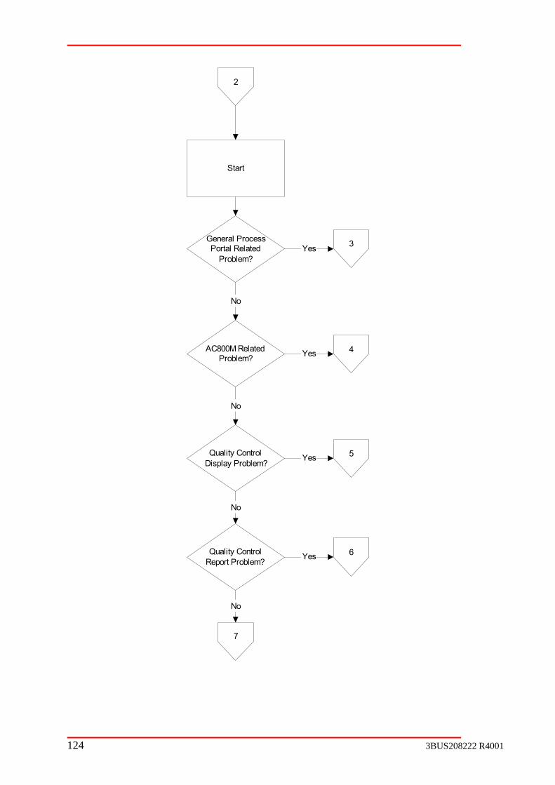
Start
General ProcessPortal Related
Problem?
3
No
AC800M RelatedProblem?
Yes
Yes 4
No
Quality ControlDisplay Problem?
Yes 5
6Quality ControlReport Problem?
No
Yes
No
7
2
124 3BUS208222 R4001
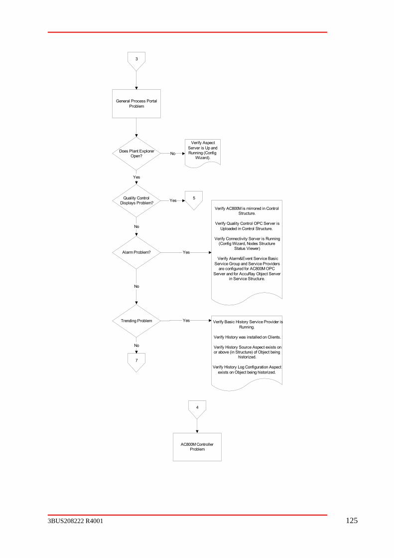
3
General Process PortalProblem
Yes
No
Verify AspectSRu
erver is Up andnning (ConfigWizard).
Quality Control Problem?
Does Plant ExplorerOpen?
Displays
No
Yes 5
Yes
Verify AC800M is mirrored in Control
Verify Connectivity Server is Running(Config Wizard, Nodes Structure
Status Viewer)
Verify Alarm&Event Service Basic
Structure.
Verify Quality Control OPC Server isUploaded in Control Structure.
Alarm Problem?
Service Group and Service Providersare configured for AC800M OPC
Server and for AccuRay Object Serverin Service Structure.
Trending Problem
No
Yes Verify Basic History Service Provider isRunning.
Verify History was installed on Clients.
Verify History Source Aspect exists onor above (in Structure) of Object being
historized.
story Log Configuration Aspectexists on Object being historized.
Verify Hi
No
7
4
AC800M ControllerProblem
3BUS208222 R4001 125

5
Quality Control DisplayProblem
Missing Data onMultiple Displays?
No
Verify ABB QCS Service and
Verify QCSApplicationNode andQCSMachineID property values onQCS Properties Aspect on Industrial ITQuality Control Object.
y OPC data quality using OPCspector.
AccuRayObjectServer services arestarted.
VerifIn
Error MessageAttempt to Redeploy Display
Displayed in place ofDisplay?
No
7
6
Quality Control ReportProblem
126 3BUS208222 R4001

7
Collect Troubleshooting Information and Call Hotline
Event Log Contents (System and Application)
iewer Hardcopy or Screen Capture
r Screen Capture
Product Release level
Detailed Fault Symptoms
How to Trigger Fault
Debug Message Viewer Contents
Quality Control System Status V
Task Manager Process List Hardcopy o
3BUS208222 R4001 127

App
A.1
A.1.1 Purpose
r automates the transfer of data from devices supported by one OPC server to devices supported by the same or a different OPC server and vice versa. Data can be
aving to neither know the details of the accomplish the same functionality. It
permits the data to be converted or operated upon during the transport and it permits mapping from 1 tag to N tags and from N tags to 1 tag. The OPC Transporter supports transfers amongst a plurality of OPC servers.
A.1.2
The OPC Transporter is a software process that accepts a configuration file(s) and based upon server called the
source and one OPC server called the target. As data is received from the source, it may ent may be used to derive
L is becoming a standard for ilar computers. Numerous products are available for
editing and validating an XML file. Because it is an ASCII file, it is ideal even for storing and e computer.
A.1.3
elected elements and then writing the entire array.
A.1.4
cut notation ‘<tag/>’.
Elements may have named attributes associated with them. They appear inside the opening be quoted; for example, ‘<tag att1=“value1”
att2=“value2”>’ has two attributes defined with string values.
endix A. OPC Transporter
Introduction
The OPC Transporte
exchanged between two devices without the user hOPC interface nor develop his own OPC client to
Overview
that file, subscribes to tags belonging to one or two OPC servers: one OPC
either be sent to the target as-is or a user-written conversion statemthe target’s value from the source and other parameters.
The OPC Transporter configuration file is an XML file. XMsharing information between dissim
sharing information within the sam
Limitations, Restrictions, Caveats
OPC does not support accessing individual elements of an array, so mappings to or from a particular element or range of elements is not supported. The OPC Transporter does permit reading an entire array and then processing only selected elements, or populating s
XML Basics
XML is a meta-language. The OPC Transporter file will only require the use of a standard subset of this language. Anyone modifying the OPC Transporter file should know about elements and attributes.
An element is akin to a statement or structure that can be nested such as, loops in procedural languages. An element is defined with the notation ‘<tag> … </tag>’, where tag is the name of the element used to open and close the content of an element. The ellipses represent the content of the element, which may be text or other elements. An empty element is represented by the short
tag. Attributes have string values which must
128 3BUS208222 R4001

nguage has reserved characters that must be escaped if used as output text. problems when trying to support expressions
supporting the less than operator or bit-wise-and operations. The escape sequence is not very ubstitution before displaying the text.
echanism that applies to an entire block of text called CDATA permit very readable conversion statements,
g the conversion algorithm as opposed to using the strict XML syntax.
A.2 Transporter File
A.2.1 File
An XML file begins with an XML version header statement and document type definition. hich release the syntax adheres. The document type
syntax of the OPC Transporter configuration file and must d
to provide an absolute or relative path to the
t
ild elements: <sub> and <transporter>. They must appear is a specified order. All <sub>
are used to define conversion algorithms that are subsequent <transporter> elements.
The transfer configuration is organized by source-target pairings defined with the from a source OPC server to a
ay be used to reverse that flow to create bi-directional transfers. The number of <transporter> elements is not restricted. The first two
ransport> element define the source and target OPC servers for that ansporter.
orter>, transfers are organized in groups that may have different OPC update rates. All mappings appear as children to the <group> element. Mappings are accomplished
akeArray>, <breakArray>, <makeFlag>, and <breakFlag>
The XML meta-laThe characters “&” and “<” in particular cause
readable although some XML tools do perform the sXML does provide an escape msections. For this application, CDATA sectionsso they will be used primarily for definin
Content
The version header specifies to wdefinition (DTD) file defines thenot be modified. The first element in the configuration file is the parent, in this case calle<OPCtransporter>; it must always be first per the XML specification. All other elements are children to this parent.
<?xml version="1.0" standalone="no"?>
<!DOCTYPE OPCtransporter SYSTEM "OPCtransporter.dtd">
<OPCtransporter>
child elements
</OPCtransporter>
The above DOCTYPE declaration requires that the DTD file be placed in the same folder as the configuration file. The line can be modifiedDTD instead.
Appendix A provides the content of the DTD file. It strictly defines the layout of the configuration file as expected by the OPC Transporter. It is documented herein in case the file is lost or corrupted. The meaning behind the cryptic syntax is explained in subsequenparagraphs and sections.
The <OPCtransporter> root element can have various numbers of two kinds of ch
elements must be enumerated first. Theseglobally shared by
<transporter> element. This defines a single-direction beamtarget OPC server. A second <transporter> element m
children of the <ttr
Within a <transp
using the <transport>, <melements.
3BUS208222 R4001 129

The basic XML file organization:
<OPCtransporter>
<sub>
…
</sub>
<transporter>
<sourceOPC> … </sourceOPC>
<targetOPC> … </targetOPC>
group>
<breakArray> … </breakArray>
<transporter>
A.2.2 Element Definitions
a
ding a ing.
<
<transport> … </transport>
<makeArray> … </makeArray>
</group>
<group>
</group>
</transporter>
…
</transporter>
</OPCtransporter>
<transporter>
The <transporter> element defines one transport path between a source OPC server andtarget OPC server. It has a required set of child elements that must appear in a specified order. The source OPC server and the target OPC server must first be declared before the mappings are defined. Mappings must be organized as children of <group> elements.
The optional attribute “id” is intended to support the ABB Debug trace facility by provimeaningful identifier by which the appropriate OPC Transporter can be selected for viewIt must be unique and to enforce this requirement, the attribute is defined to be of the IDattribute type. This causes an XML parser to validate the ID as being a unique name.
The element <transporter> may only appear as the child of the root <OPCtransporter> element.
<OPCtransporter>
<transporter id=”example”>
130 3BUS208222 R4001
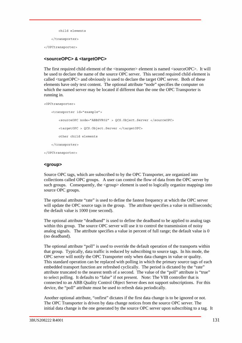
child elements
</transporter>
OPCtransporter>
<sourceOPC> & <targetOPC>
ent of the <transporter> element is named <sourceOPC>. It will e of the source OPC server. This second required child element is
other child elements
Source OPC tags, which are subscribed to by the OPC Transporter, are organized into
into
adband to be applied to analog tags within this group. The source OPC server will use it to control the transmission of noisy
a in percent of full range; the default value is 0
“poll” is used to override the default operation of the transports within
ach
trol Object Server does not support subscriptions. For this device, the “poll” attribute must be used to refresh data periodically.
Another optional attribute, “onfirst” dictates if the first data change is to be ignored or not. The OPC Transporter is driven by data change notices from the source OPC server. The initial data change is the one generated by the source OPC server upon subscribing to a tag. It
</
The first required child elembe used to declare the namcalled <targetOPC> and obviously is used to declare the target OPC server. Both of these elements have only text content. The optional attribute “node” specifies the computer on which the named server may be located if different than the one the OPC Transporter is running in.
<OPCtransporter>
<transporter id=”example”>
<sourceOPC node=”ABBSVR02” > QCS.Object.Server </sourceOPC>
<targetOPC > QCS.Object.Server </targetOPC>
</transporter>
</OPCtransporter>
<group>
collections called OPC groups. A user can control the flow of data from the OPC server by such groups. Consequently, the <group> element is used to logically organize mappingssource OPC groups.
The optional attribute “rate” is used to define the fastest frequency at which the OPC serverwill update the OPC source tags in the group. The attribute specifies a value in milliseconds; the default value is 1000 (one second).
The optional attribute “deadband” is used to define the de
an log signals. The attribute specifies a value (no deadband).
The optional attributethat group. Typically, data traffic is reduced by subscribing to source tags. In his mode, the OPC server will notify the OPC Transporter only when data changes in value or quality. This standard operation can be replaced with polling in which the primary source tags of eembedded transport function are refreshed cyclically. The period is dictated by the “rate” attribute truncated to the nearest tenth of a second. The value of the “poll” attribute is “true” to select polling. It defaults to “false” if not present. Note: The VIB controller that is connected to an ABB Quality Con
3BUS208222 R4001 131

is sent regardless of an actual change in value of the source tag. Setting “onfirst=”true”” will cause the first data change of an input tag to be processed; setting it to “false” will cause the first data change to be ignored. The default value is “true”. The value of this attribute affects all transport elements within this group except for <global> elements.
The optional attribute “id” is intended for the future feature that will allow a user to control the state of a group. It must be unique; the attribute is defined to be of the ID attribute type. The element <group> may only appear as the child of <transporter>.
<OPCtransporter>
<transporter id=”example”>
<sourceOPC node=”ABBSVR02” > QCS.Object.Server </sourceOPC>
</group>
<group rate=”5000” poll=”true”>
child elements
</group>
</transporter>
</OPCtransporter>
<branch>
A <branch> element is used to provide a base path in an OPC server’s browse tree. This base tag references that follow this element. This permits a shorthand
notation for specifying the tags. The <branch> element has one required attribute to specify hi O C applies to. The value of attribute “OPC” may be either
“source” or “target”. This element may appear as frequently as needed to redefine base paths for either OPC server. It may appear as the child of <transporter> or the child of <group>. When appearing within a <group> element, its scope is confined to the tags within that group.
nd the tag name that will be appended to it
<OPCtransporter>
<transporter id=”example”>
<sourceOPC node=”ABBSVR02” > QCS.Object.Server </sourceOPC>
<targetOPC > QCS.Object.Server </targetOPC>
<branch OPC=”source”> PM1.AC450B.FRAME1. </branch>
<group rate=”5000”>
<branch OPC=”target”> SQCS.Scanner1. </branch>
child elements
</group>
</transporter>
<targetOPC > QCS.Object.Server </targetOPC>
<group rate=”5000” onfirst=”false”>
child elements
path will be applied to all
w ch P server the branch
Any delimiter required between the base path amust be included in the <branch> value.
132 3BUS208222 R4001

</OPCtransporter>
<input> & <output>
The <input> and <output> elements declare a specific tag in either the source OPC server namespace or the target OPC server namespace, respectively. These elements are child elements used in various data mapping elements to define the tags involved in the operation. The value of this element, the OPC tag, is appended to the path specified in the last <branch>
full tag name.
ms
The elements also supports an optional “index” attribute to allow mapping a select number of array elements. This attribute is further discussed in the array mapping elements.
<mapping element>
<input> a_sourceOPC_tag </input>
<output initial=”100”> a_targetOPC_tag </output>
</ mapping element >
<assign>
ent is used to declare a simple arithmetic expression to be applied to the apping elements. The expression has one result that is sent to the
target OPC tag. Operands may be numeric literals and the source OPC (a.k.a. <input>) tags.
Input tags are mapped to variables in the expression using the optional “var” attribute on the <input> element. The value of “var” may be any legal variable name as described in section 2.3. If there is only one <input> element, its association with a variable in the expression is
r” declaration is required. Before any OPC value is used in an y must be good; otherwise, no value is sent to the target OPC tag.
The type of operators used in the arithmetic expression includes all that are supported in the Transporter Programming Language described in section 2.3. However, the operators that include the ampersand (&) and less-than (<) characters conflict with the XML meta-language.
d using either the hexadecimal character equivalent or the special escape sequences: “&” and “<” respectively. These escape sequences leave the expression
o decipher. Many XML parsers convert the escape sequences to their literal equivalents before displaying them, but some do not. If the expression requires bit-wise operations, it is suggested the <sub> element be used instead.
<mapping element>
<assign> x*100-80 </assign>
<input> a_sourceOPC_tag </input>
<output> a_targetOPC_tag </output>
element to form the
Both the <input> and <output> elements have an optional attribute called “access”. This attribute may be required by some OPC servers to define the access path to certain OPC iteor tags. See the OPC specification for use of access paths.
The <output> element has an optional “initial” value attribute. This value is sent to the target tag upon successful connection to the target OPC server regardless of the status of the source OPC server or the input tag. If the target tag is an array, each element is assigned the initialvalue. The “initial” value must be coercible into the data type of the target tag.
The <assign> elemsource OPC tags in data m
implied, so no explicit “vaexpression, its OPC qualit
They must be escape
somewhat tedious t
3BUS208222 R4001 133
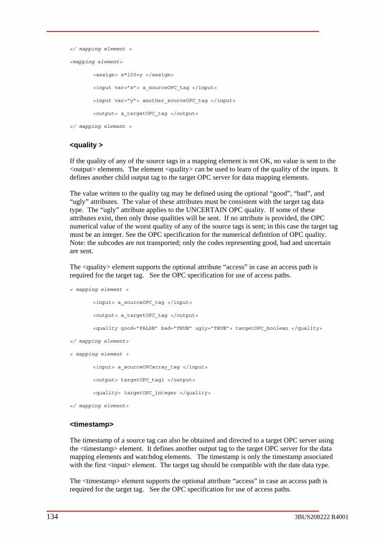
</ mapping element >
<mapping element>
<assign> x*100+y </assign>
<input var=”x”> a_sourceOPC_tag </input>
<input var=”y”> another_sourceOPC_tag </input>
<output> a_targetOPC_tag </output>
</ mapping element >
<quality >
apping element is not OK, no value is sent to the ent <quality> can be used to learn of the quality of the inputs. It
output tag to the target OPC server for data mapping elements.
quality tag may be defined using the optional “good”, “bad”, and alue of these attributes must be consistent with the target tag data
type. The “ugly” attribute applies to the UNCERTAIN OPC quality. If some of these n only those qualities will be sent. If no attribute is provided, the OPC
numerical value of the worst quality of any of the source tags is sent; in this case the target tag .
The <quality> element supports the optional attribute “access” in case an access path is the target tag. See the OPC specification for use of access paths.
< mapping element >
<input> _sourceOPC_tag </input>
<output> a_targetOPC_tag </output>
<quality good=”FALSE” bad=”TRUE” ugly=”TRUE”> targetOPC_boolean </quality>
</ mapping element>
< mapping element >
<input> _sourceOPCarray_tag </input>
<output> targetOPC_tag1 </output>
<quality> targetOPC_integer </quality>
</ mapping element>
<timestamp>
The timestamp of a source tag can also be obtained and directed to a target OPC server using the <tim ment. It defines another output tag to the target OPC server for the data mapping elements and watchdog elements. The timestamp is only the timestamp associated with the first <input> element. The target tag should be compatible with the date data type.
The <tim element supports the optional attribute “access” in case an access path is required for the target tag. See the OPC specification for use of access paths.
If the quality of any of the source tags in a m<output> elements. The elemdefines another child
The value written to the“ugly” attributes. The v
attributes exist, the
must be an integer. See the OPC specification for the numerical definition of OPC qualityNote: the subcodes are not transported; only the codes representing good, bad and uncertain are sent.
required for
a
a
estamp> ele
estamp>
134 3BUS208222 R4001

< mappi
<input> a_sourceOPC_tag </input>
t> a_targetOPC_tag </output>
-to-1, and even N-to-N. The child
elements for <transport> are <assign>, <triggeredBy>, <input>, <output>, <quality>, and >
-to-1mapping without any special processing will have one <input> child element utput> child element. The content of these children are the respective source OPC
e simple manipulation of the source data a simple arithmetic expression:
.
les in the expression. This is accomplished with the optional “var” attribute on the <input> element:
<output> a_targetOPC_tag </output>
</transport>
ng element >
<outpu
<timestamp> targetOPC_date </timestamp>
</ mapping element>
<transport >
The <transport> data mapping element declares a mapping from source OPC tags to targetOPC tags. The mapping may be from 1-to-1, 1-to-N, N
<timestamp>. These must appear as child elements in this same order. The <triggeredByelement is described in a later paragraph.
A typical 1and one <oand target OPC tags:
<transport>
<input> a_sourceOPC_tag </input>
<output> a_targetOPC_tag </output>
</transport>
To map 1-to-N in the above example, just add more <output> elements.
An <assign> element may be added to provide sombefore it is sent to the target OPC in the form of
<transport>
<assign> x*100+15.5 </assign>
<input> a_sourceOPC_tag </input>
<output> a_targetOPC_tag </output>
</transport>
In the above example, the target of the assign is implied to be the sole output tag. The input to the arithmetic expression, represented by the variable x, is implied to be the sole input tag
If the mapping is from N-to-1, the input tags must somehow be mated with variab
<transport>
<assign> x*100+y </assign>
<input var=”x”> a_sourceOPC_tag </input>
<input var=”y”> another_sourceOPC_tag </input>
3BUS208222 R4001 135

Note that mapping N-to-1 without a conversion algorithm is nonsensical and would generate an error. In the above example, to map the same result to multiple outputs (N-to-N), just add
o”. Its purpose is described in a subsequent paragraph regarding the <sub> element. Fundamentally, a function is applied to
ce output data. It is similar in usage to the <assign> element but is in any procedural language.
nput>
t-by-cial array
handling is described under
.
erred to as asynchronous; the target tags are written to in response to a change in
r=”y”> another_sourceOPC_tag </input>
A third way to cause the transport to occur is to use the <triggeredBy> element. This element sed
ssign> and before the first <input> element.
gs.
list all the <output> elements in the order of the desired mapping. A conversion algorithm can still be applied to each element of the
more <output> elements.
The <transport> element has an optional attribute, “d
the input data to produtreated like a subprogram
<transport do=”line_function”>
<input var=”x”> a_sourceOPC_tag </i
<input var=”y”> another_sourceOPC_tag </input>
<output> a_targetOPC_tag </output>
</transport>
When there are multiple source arrays, the mapping and conversion is performed elemenelement for element indices within the bounds of all source arrays. Other spe
<makeArray> and <breakArray>
When there are multiple <input> elements, the default is to subscribe to the tag in the first <input> element and read the other tags synchronously from the source OPC server. In this manner, the arrival of new data for the first tag becomes the triggering mechanism for the transport to the target. Optionally, all inputs can trigger the transport to the target. This mode is refeach or any source tag. To select asynchronous mode, use the optional attribute “mode” and set it to “async”. This attribute can also be set to “sync”, but this is the default if the attribute is missing.
<transport mode=”async”>
<assign> x*100+y </assign>
<input var=”x”> a_sourceOPC_tag </input>
<input va
<output> a_targetOPC_tag </output>
</transport>
refers to a global tag that is used to trigger the exchange as described in another section. Itwill override the default mode and the explicit “async” mode. The trigger tag cannot be uas an input source. The <triggeredBy> element must appear after the optional <a
<breakArray>
The mapping element <breakArray> is to be used to map a source array to discrete target taThe child elements for <breakArray > are <assign>, <triggeredBy>, <input>, <output>, <quality>, and <timestamp> in that order. As children of <breakArray>, provide one <input> element that is the source array and then
136 3BUS208222 R4001

source array using an inline <assign> element or the “do” attribute exactly like the <transport> element.
ts an optional “index” attribute to allow mapping a select he set of target tags. This index must be appropriate for the
</assign>
</input>
<output> targetOPC_tagN </output>
<output index =”7”> targetOPC_tag2 </output>
<output index = “11”> targetOPC_tag3 </output>
</breakArray>
By default, the <breakArray> transfer will occur upon a change in value of the source array. transport to occur is to use the <triggeredBy> element as described
a th <triggeredBy> element must appear after the optional <assign> and before the <input> element.
te source tags into a single target array is complicated by the Transporter subscribed to each source tag,
d
s
upper bound of the target array. These are followed by a single <output> element. A
The <output> element suppornumber of array elements to tsource array as defined by the lower and upper bounds of the array. The input array is indexed into by the “index” attribute to acquire the value to map to the target tag. Array element indexing is 1-based.
The optional “var” attribute is ignored by the <breakArray> element since there can only beone <input> element and the <output> elements collectively represent one output array.
<breakArray>
<assign> x*10-2
<input> sourceOPCarray_tag
<output> targetOPC_tag1 </output>
<output> targetOPC_tag2 </output>
</breakArray>
<breakArray>
<input> sourceOPCarray_tag </input>
<output index=”3”> targetOPC_tag1 </output>
A second way to cause thein no er paragraph. The
<makeArray>
The mapping of discreasynchronous arrival of source data. If the OPC then the target array would be sent once per element change. If the OPC Transporter woulwait until a full set of source values has arrived before sending the target array, the target system may never get the array if one of the elements never changes. The mapping element <makeArray> is used to map discrete source tags into a single target array. The source tagare accumulated asynchronously, but at a specified frequency, they are sent as an array to thetarget OPC server.
The child elements for <makeArray > are <assign>, <triggeredBy>, <input>, <output>, <quality>, and <timestamp> in that order. As children of <makeArray>, list all the <input>elements that will be used to form the array in the desired order from the lower bound to the
3BUS208222 R4001 137
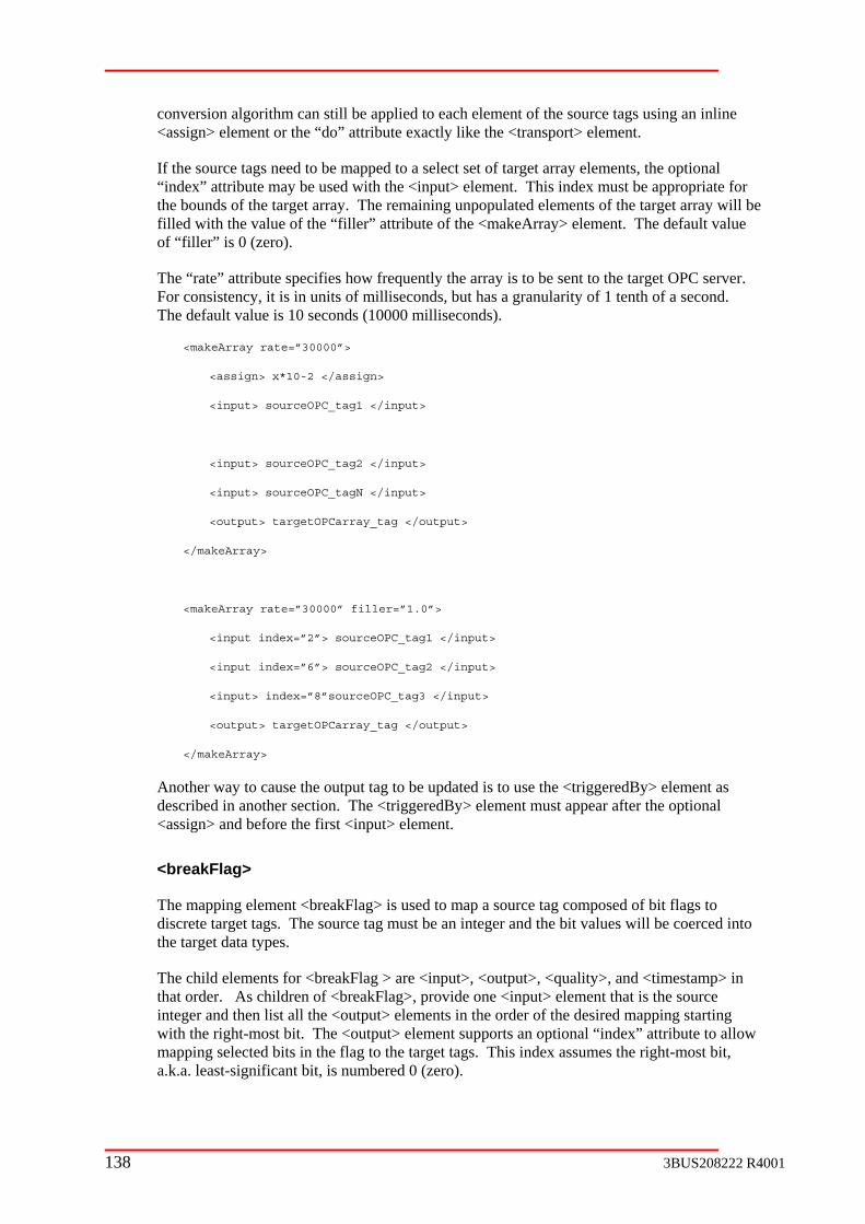
conversion algorithm can still be applied to each element of the source tags using an inline<assign> element or the “do” attribute exactly like the <transport> element.
to be mapped to a select set of target array elements, the optional ement. This index must be appropriate for
the bounds of the target array. The remaining unpopulated elements of the target array will be lle w “filler” attribute of the <makeArray> element. The default value
of “filler” is 0 (zero).
The “rate” attribute specifies how frequently the array is to be sent to the target OPC server. For consistency, it is in units of milliseconds, but has a granularity of 1 tenth of a second. The default value is 10 seconds (10000 milliseconds).
<makeArray
<assign> x*10-2 </assign>
</input>
2 </input>
</input>
targetOPCarray_tag </output>
ceOPC_tag3 </input>
_tag </output>
tag to be updated is to use the <triggeredBy> element as described in another section. The <triggeredBy> element must appear after the optional
ement.
<breakFlag>
s used to map a source tag composed of bit flags to discrete target tags. The source tag must be an integer and the bit values will be coerced into
.
The child elements for <breakFlag > are <input>, <output>, <quality>, and <timestamp> in dren of <breakFlag>, provide one <input> element that is the source
integer and then list all the <output> elements in the order of the desired mapping starting with the right-most bit. The <output> element supports an optional “index” attribute to allow mapping selected bits in the flag to the target tags. This index assumes the right-most bit, a.k.a. least-significant bit, is numbered 0 (zero).
If the source tags need“index” attribute may be used with the <input> el
fi d ith the value of the
rate=”30000”>
<input> sourceOPC_tag1
<input> sourceOPC_tag
<input> sourceOPC_tagN
<output>
</makeArray>
<makeArray rate=”30000” filler=”1.0”>
<input index=”2”> sourceOPC_tag1 </input>
<input index=”6”> sourceOPC_tag2 </input>
<input> index=”8”sour
<output> targetOPCarray
</makeArray>
Another way to cause the output
<assign> and before the first <input> el
The mapping element <breakFlag> i
the target data types
that order. As chil
138 3BUS208222 R4001
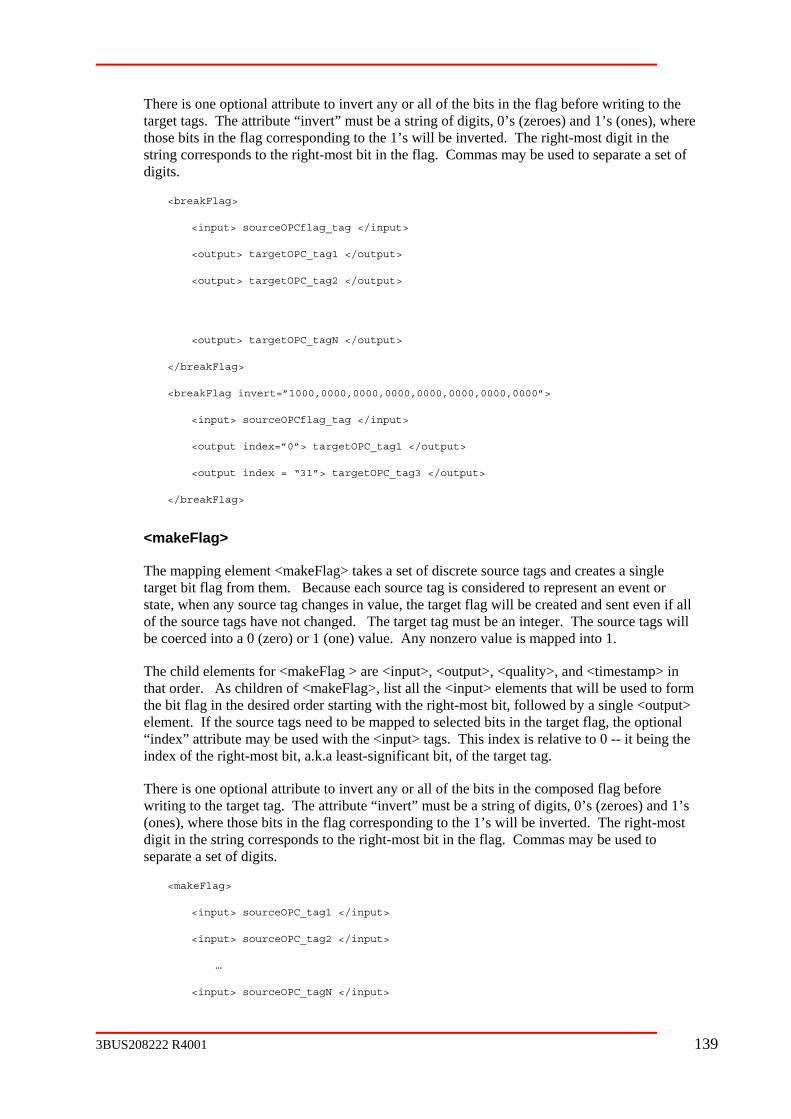
attribute to invert any or all of the bits in the flag before writing to the ute “invert” must be a string of digits, 0’s (zeroes) and 1’s (ones), where
those bits in the flag corresponding to the 1’s will be inverted. The right-most digit in the ds to the right-most bit in the flag. Commas may be used to separate a set of
digits.
</output>
00,0000,0000,0000,0000,0000,0000”>
apping element <makeFlag> takes a set of discrete source tags and creates a single
will
in will be used to form
the bit flag in the desired order starting with the right-most bit, followed by a single <output> tags need to be mapped to selected bits in the target flag, the optional be used with the <input> tags. This index is relative to 0 -- it being the
’s st
…
<input> sourceOPC_tagN </input>
There is one optionaltarget tags. The attrib
string correspon
<breakFlag>
<input> sourceOPCflag_tag </input>
<output> targetOPC_tag1
<output> targetOPC_tag2 </output>
<output> targetOPC_tagN </output>
</breakFlag>
<breakFlag invert=”1000,00
<input> sourceOPCflag_tag </input>
<output index=”0”> targetOPC_tag1 </output>
<output index = “31”> targetOPC_tag3 </output>
</breakFlag>
<makeFlag>
The mtarget bit flag from them. Because each source tag is considered to represent an event or state, when any source tag changes in value, the target flag will be created and sent even if allof the source tags have not changed. The target tag must be an integer. The source tagsbe coerced into a 0 (zero) or 1 (one) value. Any nonzero value is mapped into 1.
The child elements for <makeFlag > are <input>, <output>, <quality>, and <timestamp>that order. As children of <makeFlag>, list all the <input> elements that
element. If the source“index” attribute mayindex of the right-most bit, a.k.a least-significant bit, of the target tag.
There is one optional attribute to invert any or all of the bits in the composed flag before writing to the target tag. The attribute “invert” must be a string of digits, 0’s (zeroes) and 1(ones), where those bits in the flag corresponding to the 1’s will be inverted. The right-modigit in the string corresponds to the right-most bit in the flag. Commas may be used to separate a set of digits.
<makeFlag>
<input> sourceOPC_tag1 </input>
<input> sourceOPC_tag2 </input>
3BUS208222 R4001 139

<output> targetOPCflag_tag </output>
</input>
</input>
t>
</makeFlag>
<trigger> & <triggeredBy
Some source tags need to be sent on a particular event rather than a change in its value. Arrays f ch array element that changes in value would cause the entire ar igger> element defines a tag that may be used by <transp kArray> elements to trigger their transfers. The same trigger m ing elements. Even though a trigger is defined within a specific group, its range is global within the same <transporter> element; however, the <trigger earlier in the XML file than any element that refers to it. The value of the trigger tag is not used; only a change in value causes the trigger to occur. The element <trigger> has one required attribute, called “var”, to give the tag a variable name that can be r er elements. This name must be unique throughout the XML file and must adhere to the variable name restrictions. It has the attribute type ID to ensure uniqueness. The optional attribute, “access”, may be required by some OPC servers to define
rigger var=”anyname”> a_sourceOPC_tag </trigger>
ggeredBy> element. The <triggeredBy> element ransport>, <makeArray>, or <breakArray>. The presence of the child
element <triggeredBy> overrides the default or any explicit transfer mode (synchronous, ent. The element <triggeredBy> has one
r to a variable name that has previously been assigned to a <trigger> element. It has the attribute type IDREF to ensure a match exists.
<triggeredBy var=”a_trigger”/>
</trigger>
=”trg”/>
<output> outputTag1 </output>
</makeFlag>
<makeFlag invert=”1000,0000”>
<input index=”2”> sourceOPC_tag1 </input>
<input index=”6”> sourceOPC_tag2
<input> index=”7”sourceOPC_tag3
<output> targetOPCflag_tag </outpu
>
all into this category where earay to be transferred. The <tr
ort>, <makeArray>, and <breaay be used for multiple mapp
> element must appear
eferenced by oth
the access path to certain OPC items or tags.
<t
The element <trigger> is referenced in a <triis a child element of <t
asynchronous, or periodic) of the parent elemrequired attribute, called “var”, to refe
Example:
<group rate=”1000”>
<trigger var=”trg”> triggerTag
</group>
<group>
<transport>
<triggeredBy var
<input> inputTag1 </input>
140 3BUS208222 R4001

<output> outputTag2 </output>
l affect the operation of the trigger mechanism. Instead of a change in value causing the transfer to occur, the periodic refresh forced by the polling operation will cause a transfer
element is a variation of the <transport> element but no source OPC data is the target to learn of the demise of the connection
to the source OPC server and to force reconnection to lost OPC servers. This element can alarm”, ”restart”, and “poll”. It takes two forms.
efined by an <input> element. While changes ceived, a user-defined value is sent to an optional target
OPC tag as defined by an <output> element. If the source tag does not change in value within <watchdog> element will write another special
possible.
If no <input> tag is provided, the OPC Transporter assumes the second form is opted and will es out or the server state is not
P G, a watchdog alarm is sent to an optional target tag as defined by an <output> element; otherwise, another value is sent to the same target tag to indicate the
he watchdog timeout will occur only once.
The “rate” attribute specifies how frequently (in milliseconds, but granularity of 1000 illiseconds) the source must arrive or the status polled before a watchdog alarm value is sent
“rate” is 180 seconds. In the monitor form, the source tag is subscribed to with an update rate of 1 second. The “alarm” attribute is what is to
g alarm is generated. The “ok” attribute is the value sent as long as the source tag is received or the OPC interface is
” must be compatible with the target tag.
In the first example, the value of “ok” is used to set a timer in the target machine that is used a ct if there is an OPC Transporter failure. The first example is
nd example is the polling form.
ok=”12”>
g </input>
g </output>
</transport>
<transport>
<triggeredBy var=”trg”/>
<input> inputTag2 </input>
</transport>
</group>
Note that the “poll” option on the <group> element that is parent of the <trigger> element wil
regardless of value returned.
<watchdog> & <heartbeat>
The <watchdog>transferred to the target OPC. It is used for
have five attributes: “rate”, “ok”, ”
The first form monitors a source OPC tag as din the value of the source tag are re
a certain period or its quality is not good, the value to the target tag. This monitoring functionality is repetitive so multiple timeouts are
poll the status of the source OPC server. If the interface timO C_STATUS_RUNNIN
status is OK. In this polling form, t
mto the target OPC. The default value for
be written to the <output> element tag when a watchdo
functioning. The values of “ok” and “alarm
as countdown device to detethe monitoring form and the seco
<watchdog rate=”10000” alarm=”0”
<input> sourceOPC_ta
<output> targetOPC_ta
</watchdog>
3BUS208222 R4001 141

<watchdog rate=”30000” alarm=”TRUE” ok=”FALSE”>
put>
he nstructed to reestablish connections to lost OPC servers. This is attribute. This optional attribute may have two values:
“manual” and “auto”. The default value is “manual” in which case the OPC Transporter will uto”, the connections will be retried after 30 seconds
inated. An OPC failure is determined by the watchdog e source OPC server status, the failure is a “bad” returned status
or no response. If the form is monitoring a source tag, the failure is a timeout on the update tag remaining bad for the timeout period. A target OPC server
dog timeout on all watchdogs configured and thus in turn force a reconnection if so opted.
ABB Quality Control Object Server does not poll” attribute must be used to cause the
at refreshed periodically (once per second). The default value of the “poll” attribute is “false”. Set it to “true” for such watchdogs. Unfortunately, this method
ay may not be very prompt in reporting watchdog
hdog> element but sends an internal value to t interact with the source OPC server. The value sent is
called a heartbeat and is incremented once per second by the OPC Transporter. It can be mise of the connection to the target OPC
o attributes: “rate”and “restart”. The “rate” defines the frequency at which the heartbeat will be sent (in milliseconds, but granularity of 1000
illiseconds). Its default value is 10 seconds (10000).
<heartbeat rate=”5000” restart=”auto”>
<output> targetOPC_tag </output>
</heartbeat>
The “restart” attribute operates the same as for the <watchdog> element. The combination of at ts dictate automatic reconnections after OPC server failures. If a
of any <heartbeat> elements, a <watchdog> element will cause the reconnection no matter what its value of “restart” is. If a target OPC
ormed based upon the <heartbeat>’s “restart” attribute.
The <sub> element is used to define a complex conversion algorithm in the form of a d in detail in a later
Language (TPL), but in essence, it permits multiple assignment statements and some flow control features. As with the <assign>
e output from the given input. It supports N inputs
<output> targetOPC_tag </out
</watchdog>
T OPC Transporter can be iaccomplished with the “restart”
not reconnect to the OPC servers. In “aand then for every 15 seconds thereafter until successful. Upon detection of an OPC server failure, both connections are termform. If the form is polling th
of the tag, or the quality of theaccess failure will force a watch
The VIB controller that is connected to an support subscriptions. For this device, the “w chdog OPC group to be
m suffer from DCOM side effects and thus timeouts.
The <heartbeat> element is similar to the <watcthe target OPC server; it does no
used for the OPC Transporter to learn of the deserver and to force reconnection to both OPC servers for situations where the source OPC server might be relatively quiet. The <heartbeat> element has one child element, <output>, to define the target OPC tag and can have tw
m
w chdogs and heartbeatarget OPC server fails and in the absence
server fails and a <heartbeat> is provided, the reconnection is perf
<sub>
procedural language. The content of the <sub> element is describeparagraph on the Transporter Programming
element, the intent of <sub> is to produc
142 3BUS208222 R4001
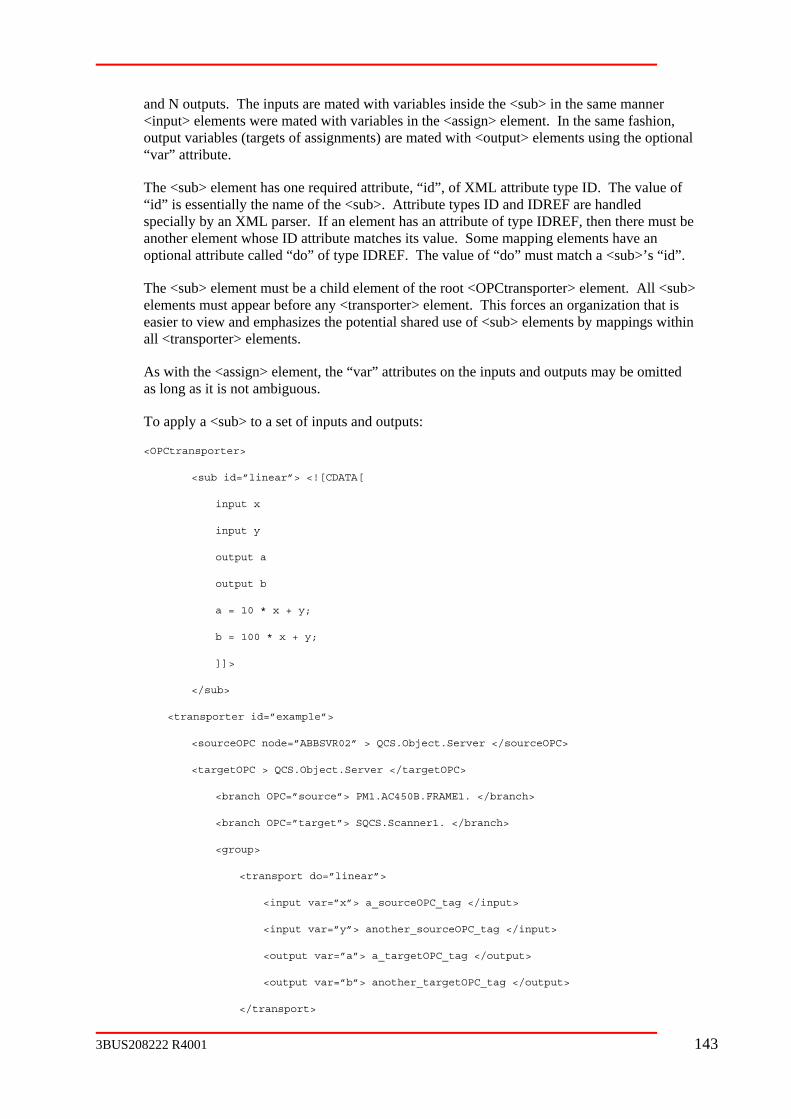
d with variables inside the <sub> in the same manner with variables in the <assign> element. In the same fashion,
output variables (targets of assignments) are mated with <output> elements using the optional
d”, of XML attribute type ID. The value of pes ID and IDREF are handled
specially by an XML parser. If an element has an attribute of type IDREF, then there must be es its value. Some mapping elements have an
optional attribute called “do” of type IDREF. The value of “do” must match a <sub>’s “id”.
ent of the root <OPCtransporter> element. All <sub> elements must appear before any <transporter> element. This forces an organization that is
sub> elements by mappings within
As with the <assign> element, the “var” attributes on the inputs and outputs may be omitted
To apply a <sub> to a set of inputs and outputs:
<OPCtransporter>
<sub id=”linear”> <![CDATA[
input x
input y
output a
output b
a = 10 * x + y;
b = 100 * x + y;
]]>
</sub>
<transporter id=”example”>
<sourceOPC node=”ABBSVR02” > QCS.Object.Server </sourceOPC>
<targetOPC > QCS.Object.Server </targetOPC>
<branch OPC=”source”> PM1.AC450B.FRAME1. </branch>
<branch OPC=”target”> SQCS.Scanner1. </branch>
t>
tput var=”b”> another_targetOPC_tag </output>
rt>
and N outputs. The inputs are mate<input> elements were mated
“var” attribute.
The <sub> element has one required attribute, “i“id” is essentially the name of the <sub>. Attribute ty
another element whose ID attribute match
The <sub> element must be a child elem
easier to view and emphasizes the potential shared use of <all <transporter> elements.
as long as it is not ambiguous.
<group>
<transport do=”linear”>
<input var=”x”> a_sourceOPC_tag </inpu
<input var=”y”> another_sourceOPC_tag </input>
<output var=”a”> a_targetOPC_tag </output>
<ou
</transpo
3BUS208222 R4001 143

</group>
</transporter>
</OPCtransporter>
<global>
y
nchronous mode option is used, the data may be
the algorithm invoked by a mapping element. Like <input>, the f
the attribute type ID to ensure uniqueness. The optional attribute, “access”, may be required by
s or tags.
The <global> element is a child of a <group> element.
<OPCtransporter>
<sub id=”linear”> <![CDATA[
input x
input y
output a
output b
a = slope * x + y;
b = 10 * slope * x + y;
]]>
</sub>
<transporter id=”example”>
<sourceOPC node=”ABBSVR02” > QCS.Object.Server </sourceOPC>
<targetOPC > QCS.Object.Server </targetOPC>
<branch OPC=”source”> PM1.AC450B.FRAME1. </branch>
<branch OPC=”target”> SQCS.Scanner1. </branch>
<group>
<global var=”slope”> a_sourceOPC_tag </global>
The handling of multiple source tags to produce one or more target values requires special attention. Source tags are typically subscribed to and a target value is generated when notification of a change in source value is received. If two or more sources are used, then, bdefault, the tag in the first <input> child element is subscribed to and the others are read synchronously. On the other hand, if the asywritten to the target OPC more often than desired. Using global variables is an alternative that avoids the overhead and delay of synchronous reads and the extra writes caused by asynchronous updates.
A <global> element defines a source tag that will be used in multiple conversion algorithms (see <sub>) as a global variable. Even though its value changes asynchronously, it will not be used until required bycontent of <global> is the name of a source OPC tag. A global variable must be a scalar oBoolean, real or integer data type. It has one required attribute, called “var”, to give theglobal tag a variable name that is referenced in conversion algorithms. This name must be unique throughout the XML file and must adhere to the variable name restrictions. It has
some OPC servers to define the access path to certain OPC item
144 3BUS208222 R4001

<transport do=”linear”>
<input var=”x”> a_sourceOPC_tag </input>
<input var=”y”> another_sourceOPC_tag </input>
put var=”a”> a_targetOPC_tag </output>
<output var=”b”> another_targetOPC_tag </output>
A.2.3 Data References
A varia tic character and the rest composed of only
28. select
31.
32. false
33. input
34.
35.
36.
37.
<out
</transport>
</group>
</transporter>
</OPCtransporter>
Variable Name
ble name must begin with an alphabealphanumeric characters. Keywords may not be used as variable names. Variable names are case-sensitive, but keywords are not. This convention applies to “var” attributes (parameter names), local names in TPL, and <global> names.
Keywords:
24. if
25. then
26. else
27. end
29. case
30. to
true
output
integer
real
boolean
3BUS208222 R4001 145
Data Type
The data type of input variables is defined by ay be scalars and arrays o upported by the OPC standard. Appropriateness for arithmetic operations is Basic.
Outputs also have standard data types, b termediate calculations. The input or the rsion algor output data type ipossible. Th rver does th lt is a scalar; otheOPC transporter will coerce an array when necessary.
Global variables must be scalars of Boolean, single, double, or one of the integer types. Local variables in TPL can be scalars of longs, doubles, and Booleans.
Arrays
Both input tags and output tags may be arrays. Whether any given array can be n output tag is e target OPC serve
In conversio at of the output tag is ignored until the result sent to the target OPC server. If any input to a conversion algorithm is an arraywill assumed to be array ined by examining the lower and upper bounds of all input arrays to find the highest lower bound and lowest upper bound. The data type of th the input adeclared first in the XML file. This may then have to be coerced into the actual data type.
A.2.4 Transporter Programming Language
The Transporter Programming Languag pecifying a complex conversion from or tags. TPL is a small subset or variation of other com Bas manipulation of data plus two flow control structures. TPL is primaril TA section of the <sub> element to a with the XML meta-language. The arithmetic expression may be emp e inline <assign> element as well.
A TPL prog ee sections: the section to declare local variables, and the algorithm section consisting of various statements. A statement is defined to be an assignment statement, an if-then-else statement, or a select-case statement. Where applicable, these statements may be nested. Statements are free form but white sp separate erals.
Comments
Comments m ar anywhere in the h the special character “!” at the beginning and end of the comment:
! a comment thing excep
Declaratio
Input and output parameters to the <sub his is primarily to force documentati f and the variable names assigned to the inputs and outputs. These decla r first in t
the source OPC server. These mf all data types s defined by Visual
ut these do not affect inresult of a convee target OPC se
ithm is coerced to the is coercion if the resu
f at all rwise, the
mapped to a left to th r to decide.
n algorithms, the form
s as well. The bounds
is ready to be, all outputs
of an output array are determ
e output array is matched to rray that is
e (TPL) provides a means of s the source tags into the target tag
mon languages such as ic. It provides for richy presented in the CDA
void complicationsloyed in th
ram has thr first section to define the parameters, the second
ace must be used to keywords from variables and lit
ay appe program. They are set off wit
containing any t exclamation points !
ns
> element must be declared. Ton of the number orations must appea he program.
146 3BUS208222 R4001

inpu
outp
The output declaration may be omitted where only one output will be generated and the implicit assi orm is used.
Local variab red. T<sub> eleme cal variable declara
data
where data_ be either “integer”, “real” or “boolean”. All integer variables are retained as 32-bit values. All real values are retained in double precision.
Arithmetic Expressions
An arithmetic expression can consist of the four primary operators (add (+), submultiply (*) bit-wis clusive-or , and two shift operators (left shift (<<) and right shift (>>)). Operands may be literals, parameter n d local names. Operand types must be consistent with the operation.
The shift operators take the number of b and. Right shifts cause the sign bit to be replicated in the leftmost bit. Left shifts result in a 0 be shifted into the rightmost bit. A negative shift count reverses the direction of the shift.
An expressi lational operators equal to (==), less than (<), less than or equal to (<=), greater than (>), greater than or equal to (>=), not equal to (<>), higher than (=>), and equal to or lower than (=<). These latter two operators pecomparisons igned integers. Thes sions and produce a Boolean result.
The operato est to lowest priority is: unary operators, shi(*, /, and &) onal o o right precedence within a prio l.
Literals are nd string constants. Integers may be presented decimal, oct ues. T constants, “0o” must prefix octal constants, and “0x” must prefix hexadecimal constants.
Real numbe ed in the standard decimal point form or in scientific notation: d.dddddEsxx, where d is a decimal digit, s is a sign, and x is a decimal digit in the exponent. To form a d cision literal, the ‘E ‘D’.
String litera thin quotation marks or within apostrophes to formThe standard rule for inserting the delimiter (whether it be quotes or apostrophestring applies: repeat the delimiter sequ
Special Boolean literals are TRUE and FALSE. In mixed mode operations, FALSE takes on the value of 0 and TRUE is –1.
t name
ut name
gnment statement f
les must also be declant. A lo
heir scope is only within that invocation of the tion takes the form:
_type name
type may
tract (-), (^), and (&)) and divide (/)), four e operators (or (|), not (~), ex
ames, global names, an
its to shift as the second oper
on may also use the re
of uns
equal to or rmit
e operators compare two expres
r precedence from high, (+, -, |, and ^), relatirity leve
ft operators, perators. Operators have left t
numeric, Boolean, aal, or hexadecimal val
as binary, he characters “0b” must prefix binary
rs may be represent
ouble pre ’ may be replaced with
ls must appear wi a literal. s) into the
entially.
3BUS208222 R4001 147

Assignme
An assignment statem the equal sign (=) then an a sion or a string literal. This is the conventional forassignment t. The character “;” assignment composed of arithm etic expression without an explicit assignment to a variable is also valid; the sole plicit dThis is calle nment.
a =
(n+1
s =
If after processing the algorithm, no assignment to the output variable (implicit or explicit) is executed, no value will be sent to the target tag.
If Stateme
A statement m ent. These conditional statements m clause if” followed expression. egins with ed by a statement. Likewise, the else-clause begins with the keyword “else” followed by a statement. The if-then and if-then-else statem i rd “end”. In the inon-Boolean expression evaluating to a nonzero value is considered true and zero is considered f
if a < 0
then x = a + 200;
else
if a == 0
end
end
Select Sta
Another con re is the sele ent in which values of the into ranges and a corresponding statement is then processed to produce a ause beg followed y a variable name used to compare against the literals in the remaining clauses. Each clause after that begins with llowed by a range literal, a colon, and then a statement or statements. Ranges may be formed by u in “case 1 to s may also be ppropriate relational operator in front of a literal as in “case >= 5”. For ce not ptional else-claused to set the target. This clause is sim followed by a statement or statements. s terminated with the keyword “end”. The case clause terminates w ” clause, t end” keyword.
sele
case 0: 0;
nt Statement
ent is a local variable or output parameter followed byrithmetic expres
statemenmat of an statements must be used to terminate
etic expressions. An arithm
d an implicit assigoutput parameter is the im
estination.
x*100 – y;
)*50;
‘high limit’
nt
ay be a conditional if-then or if-then-else statemay be nested. The if-
The then-clause b consists of the keyword “ the keyword “then” follow
by an
ent must be term nated with the keywo f-clause, a
alse.
then x = 0;
tement
ditional structu ct statement. It is a multi-part statem source are mapped result. The first cl ins with the “select” keyword b
the keyword “case” fosing the “to” keyword as 4”. Range
formed by using an aall values of the sour explicitly mapped, the o
ply the keyword “else”use can be
The select statement iith the next “case he “else” clause or the “
ct x
148 3BUS208222 R4001

case 1 to 4: 1;
case
then 2;
end
else 4;
end
Example <sub> Element
<sub
<![CD
Boolean flag
x0010) | g and cflag ar !
if (flag & 0x10) <> 0
case
case >100: 2;
3;
end
</sub>
A.3 Operation
A.3.1 Invocation
The OPC Tr runs under a servi pon XML configuration files created by another process or processes. The service, OPCTService.exe, must be installed using either e or t w:
OPCTService.exe –i
>= 5:
if y > 0
else 3;
ID=”sample”>
ATA[
input ad
flag = (bflag & 0 (cflag >> 2); ! bfla e global
then
select ad
< =0: 0;
case > 10: 1;
case > 1000:
else
ad * 100 + 10;
end
]]>
ansporter ce that will operate u
the RUN command lin he Command Prompt windo
3BUS208222 R4001 149

The primary ule is OPCtransporter.exe. It must be registered in order for the service to be able to run it. The service and main module both should be located in the same directory
The OPC Tr service log t log. Intranslate the event view file containing the messages. T .dll; it ame directory as the other OPC Transporter executables.
It is intended that the OPC Transporter can support multiple configuration files e been indepe veloped. The se L configuration files upon activation. These files must be registered in the Registry under the path “HKEY_LOCAL_MACHINE/SOFTWARE/ABB Inc./OPCTransporter” in a user-named folder. The he value name “XMLfilepath” and its value mqualified pa ile. Fo rge number of files, the value name “XMLfolderpath” can be used to number of XML files. The OPC Transporter will try to process each file that qualifies as an OPC Transporter file.
The OPC Transporter also makes use of the ABB debug utility for debugging activities such as displaying current state and enabling the display messages as data is processutility, ABB register e accparticular user. Using “dcomcnfg” modify“ABBDebugTool.CABBTraceEvents”. ABBDebugClient.exe must be used to view the debug utility d enable OPC Transporter output to the utility.
A.3.2 Error reco
Event Log
The OPC Transporter files errors it detects with the NT system event log as a rapplication, ransporter” record informational, warning and fatal errors messages. All compilation errors are reported here. Temporal warnings due to loss of connections may appear frequently if the system is unstable.
The service also reports errors via this same log; its name is “OPCTservice”.
The event lo file for displaying language-dependent text. Tcalled OPCT to OPC e same asTransporter executable.
Debug mo
The OPC Transporter operation can be observed using the ABB debug utility using either the Mode or Ac ns. The OPC Transporter will direct output to the for Mode selections. The mode selectio
38. ssag
39. nt log messages
40. mess
The Activity window displays the following integer values:
OPC Transporter mod
.
ansporter and its event codes, the
events to the application evener must be supplied a resource
order to
his file is OPCTmsgs must be copied to the s
that may havndently de rvice needs to locate these XM
folder must contain tth name to an XML f
ust be a fully r a system that requires a la
define a folder containing any
ed. This ount of a Debug.exe, must be ed and configured to run under th
the “identity” properties of
messages an
rding
egistered namely, “OPCT . The OPC Transporter will
g requires a messagemsgs.dll. The path
his file is the OPC Tmsgs.dll is assumed to be th
des
tivity menu optio trace windowns are:
Enable input/output me es
Display eve
Enable poll/watchdog ages
150 3BUS208222 R4001

41.
42. Source OPC server state
43. Target OPC server state
44. OPC data change events
45. Watchdog cycles
46. Poll cycles
47. Reconnect cycles
The state information is intended for an ABB engineer, but in short, zero is good and nonzero isn’t:
1 = inactive
2 = initializing
3 = bad tag in configuration file
4 = bad xml configuration file
5 = bad assign element in configuration file
6 = mismatch of data types
7 = setup error
8 = no connection to OPC server
9 = disconnected from OPC server
10 = shutdown requested by OPC server
11 = group error reported by OPC server
12 = process error (runtime error of various flavors)
13 = data type coercion error
14 = tag access error
15 = lost reference to OPC server
A.3.3 Error recovery
The module OPCtransporter, as a result of a connection loss with an OPC server, performs error recovery; otherwise, all errors are considered fatal. Upon initial activation and if there is no connection to either OPC server, an attempt will be made to establish a connection once every 15 seconds.
If an OPC server shuts down some time after a connection had been established, the module will wait 30 seconds before trying to connect again, and then it will retry every 15 seconds.
When connection to an OPC server is lost without it being a formal shut down by the OPC server, recovery can be automatically initiated via an option with the <watchdog> element.
Transporter state
3BUS208222 R4001 151

A.4 Document Type Definition <!ELEMENT OPCtransporter (sub*, transporter*)>
<!ELEMENT transporter (sourceOPC, targetOPC, (group | branch | watchdog |
global | trigger | transport | breakArray | makeArray |
akeFlag)*>
<!ATTLIST group rate CDATA "1000"
| true) "true"
id ID #IMPLIED>
<!ELEMENT global (#PCDATA)>
<!ATTLIST global var ID #REQUIRED
acce
<!ELEME
<!ATTLIST t
access CDATA #IMPLIED>
<!ELEMEN a
<!ELEMENT sub (#PCDATA)>
<!ATTLI
<!ELEMENT input (#PCDATA)>
IED
)>
heartbeat)*)>
<!ATTLIST transporter id ID #IMPLIED>
<!ELEMENT sourceOPC (#PCDATA)>
<!ATTLIST sourceOPC node CDATA #IMPLIED>
<!ELEMENT targetOPC (#PCDATA)>
<!ATTLIST targetOPC node CDATA #IMPLIED>
<!ELEMENT group (branch |
breakFlag | m
deadband CDATA "0"
poll (false | true) "false"
onfirst (false
<!ELEMENT branch (#PCDATA)>
<!ATTLIST branch OPC (source | target) #REQUIRED>
ss CDATA #IMPLIED>
NT trigger (#PCDATA)>
rigger var ID #REQUIRED
T ssign (#PCDATA)>
ST sub id ID #REQUIRED>
<!ATTLIST input var CDATA #IMPL
index CDATA #IMPLIED
access CDATA #IMPLIED>
<!ELEMENT output (#PCDATA
<!ATTLIST output var CDATA #IMPLIED
index CDATA #IMPLIED
initial CDATA #IMPLIED
152 3BUS208222 R4001

ality (#PCDATA)>
DATA #IMPLIED
bad CDATA #IMPLIED
<!ATTLIST timestamp access CDATA #IMPLIED>
<!ELEMENT triggered
<!ATTLIST triggeredBy var IDREF #IMPLIED>
<!ELEMENT transport (assign?, triggeredBy?, input+, output+, quality?, timestamp?)>
<!ATTLIST transport do IDREF #IMPLIED
mode (s | async) "
<!ELEMENT breakArray (assign?, triggeredBy?, input, output+, quality?, timestamp?)>
<!ATTLIST breakArray do IDREF #IMPLIED>
<!ELEMENT makeArray (assign?, triggeredBy?, input+, output, quality?, timestamp?)>
<!ATTLIST makeArray do IDREF #IMPLIED
kFlag (input, output+, quality?, timestamp?)>
keFlag (input+, output, quality?, timestamp?)>
<!ELEMENT watchdo
<!ATTLIST watchdog rate CDATA "180000"
restart (auto | manual) "manual"
poll (false | true) "false"
alarm CDATA #REQUIRED
ok CDATA #REQUIRED>
<!ELEMENT heartbeat (output)>
<!ATTLIST h tbeat rate CDATA "1
restart uto | manual) "manu
access CDATA #IMPLIED>
<!ELEMENT qu
<!ATTLIST quality good C
ugly CDATA #IMPLIED
access CDATA #IMPLIED>
<!ELEMENT timestamp (#PCDATA)>
By EMPTY>
ync sync">
filler CDATA "0"
rate CDATA "10000">
<!ELEMENT brea
<!ATTLIST breakFlag invert CDATA "0">
<!ELEMENT ma
<!ATTLIST makeFlag invert CDATA "0">
g (output? | (input, output?, timestamp?))>
ear 0000"
(a al">
3BUS208222 R4001 153

A.5 ition
A.5.1
::= <parameter_declarator> | <local_declarator>
<variable> ::= output_parameter | local_name
<identifier> ::= input_parameter | output_parameter | global_name | local_name
<boolean_literal> ::= true | false
<statements> ::= <statement> | <statements> <statement>
<statement> ::= <assignment> | <if_statement> | <select_statement>
<assignment> ::= <expression>; | <variable> = <expression>; |
string_literal | <variable> = string_literal
<if_stateme := if <expression <then_clause> end
if <expression> <then_clause> <else_clause> end
<then_clause> ::= then <statements>
<else_clause> ::= else <statements>
<select_statement> ::= select <identifier> <case_clauses> end |
select <identifier> <case_clauses> <else_clause> end
clause> | <case_clauses> <case_clause>
<signed_literal> |
<secondary_op> ::= + | - | | | ^
<relational_op> ::= == | <> | > | >= | => | < | <= | =<
<binary_op> ::= <shift_op> | <primary_op> | <secondary_op> | <relational_op>
<factor> ::= numeric_literal | <boolean_literal> | <identifier> | (<expression>)
<expression> ::= <factor> | <unary_op> <factor> | <expression> <binary_op> <factor>
TPL Formal Defin
<program> ::= <declarations> <statements>
<declarations> ::= <declaration> | <declarations> <declaration>
<declaration>
<parameter_declarator> ::= input name | output name
<local_declarator> ::= <type_specifier> name
<type_specifer> ::= integer | real | boolean
nt> : > |
<case_clauses> ::= <case_
<case_clause> ::= case <range> : <statements>
<signed_literal> ::= numeric_literal | -numeric_literal
<range> ::= string_literal | <boolean_literal> |
<relational_op> <signed_literal> | <signed_literal> to <signed_literal>
<unary_op> ::= - | ~
<shift_op> ::= >> | <<
<primary_op> ::= * | / | &
154 3BUS208222 R4001

string_l delimited by ‘ or by “. To include the delimiter in the string, use ‘’ or “”, respectively.
eger or real. Integers are a sequence of digits 0 to 9 depending upon the
ision, and D for double precision. Numeric literals are not sensitive to case.
na of alp .
arameter, global_name, and local_name are classes of name.
iteral is a sequence of characters
numeric_literal is intbase and A to E if hexadecimal. Binary integers are prefixed by 0B, octal integers by 0O, andhexadecimal integers by 0X. Real constants permit the standard decimal point form or scientific notation: d.dddddEsdd or d.dddddDsdd; where d is a decimal digit and s is the sign + or -, E is for single prec
me is an identifier that begins with an alphabetic character followed by a sequencehanumeric characters and must not match a keyword. Names are sensitive to case
input_parameter, output_p
Comments are delimited by !; they are treated as whitespace.
3BUS208222 R4001 155
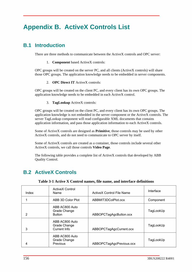
App
B.1 Introduction There are three methods to comm te en the ActiveX controls and OPC server:
Component based ActiveX controls:
OPC groups will be created on the server PC, and all clients (ActiveX controls) will share those OPC groups. The application knowledge nee e e
OPC D c on ls:
OPC groups will be created on the client PC, and every client has its own OPC groups. The a lication knowle e needs to ed ea ive
3. TagLookup ActiveX controls:
OPC groups will be created on the client PC, and e ienapplication knowledge is not em ver component or the ActiveX controls. The server TagLookup component will read configurable XML documents that contains application inform on, and pa a tion ati
Some of ActiveX controls are designed as , those controls mA iveX controls, d do not ne to com ate OPC s
S iveX c c s ain e cActiveX controls, we call those controls Video Page.
T g tabl a c te t of Ac ontQuality Control.
B.2 ActiveX Controls ti tr e file na d
Index tiveX Control
ame A tiveX C ile
endix B. ActiveX Controls List
unica betwe
1.
ds to b mbedded in server components.
2. irect IT A tiveX c tro
pp dg be emb ded in ch Act X control.
very cl t has its own OPC groups. The bedded in the ser
ati ss those pplica inform on to each ActiveX controls.
Primitivemunic
ay be used by other erver by itself. ct an ed to
ome of Act ontrols are reated a a cont er, thos ontrols include several other
he followin e provides omple lis tiveX c rols that developed by ABB
Table 3-1 Ac ve X Con ol nam s, me, an interface definitions
AcN c ontrol F Name Interface
1 ABB 3D Color Plot ABBMIT3DColPlot.o ponent cx Com
2
ABB AC800 Auto Grade Change Button ABBOPCTagAgcButton.ocx
TagLookUp
3
A Grade Change Current Info ABBOPCTagAgcCu
ABB C800 Auto
rrent.ocx TagLookUp
4
ABB AC800 Auto Grade Change Previous ABBOPCTagAgcPrevious.ocx
TagLookUp
156 3BUS208222 R4001

5 ABB Alarm and EvDisplay AEdisplay.ocx ent
6 ABB Animated Command Button ABBAnCmd.ocx Primitive
7 ABBAutoCfgGrid.ocx TagLookUp ABB Auto Grid
8 TagLookUp ABB Auto Plot ABBAutoPlotCtl.ocx
9 Component ABB CD Actuator Profile 2 ABBCDActProf.ocx
10 ABBCDMapping.ocx TagLookUp ABB CD Mapping ActiveX Control
11 Primitive ABB Chart Control ABBChart.ocx
12 CommandButtons.ocx TagLookUp ABB Command Button ABB
13 TagLookUp
ABB Enhanced Auto Grid (Used Tag Lookup Service) ABBMSFlexGrid_TL.ocx
14 MITGradeChange.ocx Component ABB Grade Change Control ABB
15 TagLookUp ABB Indicator Control ABBIndicator.ocx
16
Big OPC Direct IT
ABB Measure ITGraphic Display Control ABBMITNumberDisplay.ocx
17 MITContour.ocx Component ABB Measure IT Contour Map Control ABB
18 cx
Component
ABB Measure IT Frame & Measurement Popup Selection ABBMITFrameMeasPopup.o
19 cx
Component
ABB Measure IT Frame & Measurement Selection Library ABBMITFrameMeasSelect.o
20
ABB Measure IT Frame Overview Control ABBMITFrameOverview.ocx
Component
21
ABB MeasurFrames PanControl ABBMITFramesPanel.ocx
Component e IT el
22
ABB Measure IT ummary
ABBMI uction .ocx omponProduction S
Control TProd SumC ent
23 IT
Profile Control ABBMITProfile.ocx Component ABB Measure
3BUS208222 R4001 157

24 Sample Check Setup
ABBMITSamChkSUSP.ocx OPC Direct
ABB Measure IT
Control (SP) IT
25
Scanner
on ompon
ABB Measure IT
Operation/IndicatiControl ABBMITSPOpInd.ocx
C ent
26 Sensor Control
ABB Measure IT Results
ABBMITSensorResults.ocx Component
27 Control ABBMITSensorStatus.ocx Component
ABB Measure IT Sensor Status
28
ABB Measure IT SP OPC Direct ITGlobal Standardize
Interval Control ABBMITSPGlobalStdz.ocx
29
OPC Direct ITABB Measure IT SP Measure Setup Control - Composite Scale Factor ABBMITSPMeasSetup.ocx
30 ABB Measure IT SP
canSetup.ocx Component Scan Setup Control ABBMITSPS
31 p.ocx
Component/ OPC Direct IT
ABB Measure IT SP Single Point Setup Control - Operator Entry ABBMITSPSinglePtSetu
32 Viewer ABBMITAPCodeViewer.ocx
ent
ABB MeasureIT Active & Preliminary Grade/Shade Code Compon
33
ABB MeasureIT Color Reflectance Plot ActiveX Control ABBMITColorRefl.ocx
TagLookUp
ABB Measure
34 RepoContr
IT Excel Sensor
rting ActiveX ol ABBMITExcelRpts.ocx
35 Selector ABBMITPrelimSelect.ocx
ABB MeasureIT Preliminary Grade/Shade Code OPC Direct IT
36 IT Color Meas
Selector ABBMITColorSelector_TL.ocx TagLookUp ABB M
37 Measurement
.ocx TagLookUp
ABB MIT Color
Overview ABBMITColorMOV
158 3BUS208222 R4001

38 Component ABB MIT Color Sensor Status ABBMITColSenSts.ocx
39 ITColorTrends.ocx ABB MIT Color Trends ABBM Component
40 ABB MIT Scanner Position Display ABBMITSPPosDsp.ocx Component
41 ABB ABBMSFlexGrid.ocx Primitive MSFlexGrid
42 ABB Multi Plot ABBMultiPlotCtl.ocx Primitive
43 Text
Box Control ABBNumericTextBox.ocx Primitive ABB Numeric
44 Direct ITABB OPC Banner Control ABBOPCBanner.ocx OPC
45 ABB OPC Tag AGC Level 1 Control ABBOPCTagAGCL1.ocx TagLookUp
46 ABB OPC TAg AGC Level 2 Control ABBOPCTagAGCL2.ocx TagLookUp
47 Tag Level
ABBOPCTagL1.ocx TagLookUp ABB OPC1 grid
48 C Tag Level
1 singleline TagLookUp ABB OPABBOPCTagL1C.ocx
49 ABB OPC Tag Level 1 Vertical ABBOPCTagL1V.oc TagLookUp x
50 ABB OPC T2 grid ABBOPCTagL2.ocx Up ag Level TagLook
51 ABB OPC Tag Level 2 singleline ABBOPCTagL2C.ocx TagLookUp
52 ABB OPC Tag Speed Control ABBOPCTagSpeed. Up ocx TagLook
53
ABB OPC Trend Control (QCIndependent) ABBOPCTrends2.oc
S x
54 ABB OPCDirectIT Viewer ABBOPCDirectITViewer.ocx
55 ABB Resize ActiveX Control ABBResizeControl.ocx Primitive
56 ABB Roll Data Grid Control ABBRollDataGrid.ocx Component
57 ABB Roll Set Profile Display Control ABBRollSetProfile.oc t x Componen
58 ABB RollSet Chart Control ABBRSChart.ocx Primitive
3BUS208222 R4001 159

59 ABB RollSeConfiguration Control ABBRollSetConfig.o nt t
cx Compone
60 ABB Scanner Operation/Indication ABBSPOpInd.ocx Component
61 ABB Scanner Position Display ABBSPPosDsp.ocx ent Compon
62 ABB Split Controls ABBSplitControl.ocx Primitive
63 ABB SWS ALabel Control LabelAlarm.ocx
larm
64 ABB SWS ASensor Con ABBSWSAshCtl.ocx ponent sh
trol Com
65 ABB SWS Basis Weigth Sensor ABBSWSWeight.ocx
66 ABB SWS Caliper Control AbbCaliper.ocx
67 Component ABBSWSCharting.ocx Primitive ABB SWS Chart
68 ABB SWS Color Control ABBSWSColor.ocx
Component/ OPC Direct IT
69
ABB SWS Fiber Orientation Sensor Control ABBSWSFiber.ocx
70 Control ABBSWSFrame.ocx ABB SWS Frame
71 ABB SWS Gap Sensor Control ABBSWSGap.ocx
72 ABB SWS Gloss Control ABBSWSGloss.ocx
73 ABB SWS Grid Control ABBGrid.ocx Primitive
74 ABB SWS Microwave Moistrue Control microwave.ocx
75 ture
ture.ocx ABB SWS MoisControl ABBSWSMois
76 ABB SWS OptipControl ABBSWSOptipak.ocx ack
77 ABB SWS Ratio Control ABBSWSRatio.ocx
78 ABB SWS Smoothness Control ABBSWSSmoothness.ocx
79 ABB SWS ABBSWSTemperature.oc x
160 3BUS208222 R4001

Temperature SeControl
nsor
80
ABB Tag Lookup Menu Selector ActiveX Control ABBTagLookupSelector.
p ocx
TagLookU
81 ABB Text Entry Box ABBTextEntryBox.ocx Primitive
82
ABB Video for Measure IT Color Reports ABBVideoColorReports.ocx
Video Page
83
ideo for Measure IT Video Page
ABB V
Combined Roll Set Summary Display ABBVideoMITRollSet.ocx
84 Measure IT Fiber Orientation Display ABBVideoMITFOCtrl.ocx
Video Page ABB Video for
85
ABB Video for Measure IT Frame Overview ABBVideoMITFrmOverview.ocx
Video Page
86
ABB Video for Measure IT Measurement Status ABBVideoMITMeasStatus.ocx
Video Page
87
ABB Video for Measure IT MIS Reports ABBVideoMITMISReports.ocx
Video Page
88
ABB Video for Measure IT Profile Contour Maps ABBVideoMITContour.ocx
Video Page
89
ABB Video for Measure IT Sensor Reports
ABBVideoMITSensorReports.ocx
Video Page
90
ABB Video for Roll Set Summary (Current Set Data) ABBVidRSCurrSetData.ocx
Video Page
91
ABB Video for Roll Set Summary Last Set Data ABBVideoLastRollSet.ocx
Video Page
92 Scanner Setup Display ABBVideoMITSPSetup.ocx
Video Page ABB Video MIT Multi
93 ABB3DSca x Primitive tterGraph ABB3DScatterGraph.oc
94 ABBMenu ABBMENU.OCX
95 ABBOPCMonitorView ABBOPCMonitorView.ocx
3BUS208222 R4001 161

96 Menu Assist 1.2
Control ARMenuAssist.ocx Primitive AR
162 3BUS208222 R4001

Appendix C. TagLookUp ActiveX C
C.1 Introduction All ActiveX controls follow the TagLookUp guideline on tags XMdifferent controls have different usage; some controls require a special XML setting. The following topic provides user guide and tags XML setting for mo veX
C.2
C.2.1
a display and entry. It the user to change some
at runtime.
C.2.2 Functionality
Supported Data Types
The ABB Auto Grid supports the following data types:
1. Integer – VB data types vbInteger or vbLong as either scalar values or arrays.
2. Float – VB data types vbSingle or vbDouble as either scalar values or arrays.
3. Duration Time – VB data type vbLong as either scalar values or arrays that represent a value in milliseconds. The value is displayed and entered using the IOS standard duration time format.
ue k
The manner in which data is presented depends on whether the data is a scalar value, an array of values or a mixture of scalars and arrays.
Scalar A
<Tag ID="Reel Weight"> M03CD1:DPT.scalar1</Attri>
ontrols
L setting. However,
st commonly used Acticontrol.
ABB Auto Grid
Introduction
The ABB Auto Grid ActiveX control is a general-purpose grid for datsupports most basic data types, is XML configurable and allowsvisual aspects of the display
4. Boolean – VB data type vbBoolean as either scalar values or arrays. The valcan be displayed as either the Boolean value (“True” or “False”) or as a checbox.
5. String – VB data type vbString as either scalar values or arrays.
Visual Appearance
ttriIDs only
<Control ID="MyGrid">
<Attri ID="Value">Svr02:P </Tag> <Tag ID="Reel Moisture"> <Attri ID="Ratio">Svr02:PM03CD1:DPT.scalar2</Attri>
3BUS208222 R4001 163

<Attri ID="Value">Svr02:PM03CD1:DPT.scalar3</Attri> </Tag> </Control>
A ay AttriIDs only
<Control ID="MyGrid"> <Tag ID="Reel Weight"> <Attri ID="Value">Svr02:PM03CD1:DPT.array1</Attri> </Tag> <Tag ID="Reel Moisture">
rr
<Attri ID="Value">Svr02:PM03CD1:DPT.array2</Attri> <Attri ID="Ratio">Svr02:PM03CD1:DPT.array3</Attri>
</Tag> </Control>
Table 3-2 Array value and ratio table
Reel Weight
Reel Moisture
Value Value Ratio
0 Array1(0) Array2(0) Array3(0)
1 Array1(1) Array2(1) Array3(1)
2 Array1(2) Array2(2) Array3(2)
N Array1(n) Array2(n) Array3(n)
<Tag ID="Reel Weight"> <Attri ID="Value">Svr02:PM03CD1:DPT.scalar1</Attri> </Tag> <Tag ID="Reel Moisture"> <Attri ID="Value">Svr02:PM03CD1:DPT.array2</Attri> <Attri ID="Ratio">Svr02:PM03CD1:DPT.array3</Attri> </Tag> </Control>
TagIDs containing scalar only AttriIDs will be presented at the top of the grid.
Table 3-3 Mixed scalar and array AttriIDs
Mixed scalar and array AttriIDs
<Control ID="MyGrid">
Value
Reel Weight Scalar1
Reel Moisture
Value Ratio
0 Array2(0) Array3(0)
1 Array2(1) Array3(1)
2 Array Array3(2) 2(2)
n Array2(n) Array3(n)
Mixed AttriIDs within a TagID
164 3BUS208222 R4001

l ID="MyGrid"> ID="Reel Weight">
ID="Value">Sv D1:DPT.scalar1</Attri> </Tag> <Tag ID="Reel Moisture"> <Attri ID="Value">Svr02:PM03CD1:DPT.array2</Attri>
"Max">Svr02:PM03CD1:DPT.Maxscalar1</Attri> "Ratio">Svr02:PM03CD1:DPT.array3</Attri>
<Attri ID="Max">Svr02:PM03CD1:DPT.Maxscalar2</Attri> ">Svr02:PM03CD1:DPT.Minscalar</Attri>
containing scalar only AttriIDs will be presented at the top of the grid. When TagIDs contain both scalar and array AttriIDs, the scalar AttriIDs apply to the array AttriID they follow. In this case, if scalar AttriIDs precede the definition of any array AttriID, an error is generated.
Table 3-4 Mixed AttriIDs within a TagID
<Contro <Tag <Attri r02:PM03C
<Attri ID= <Attri ID=
<Attri ID="Min </Tag> </Control>
TagIDs
Value
Reel Weight Scalar1
Reel Moisture
Value Ratio
Max Maxscalar1 Maxscalar2
Min Minscalar
0 Array2(0) Array3(0)
1 Array2(1) Array3(1)
2 Array2(2) Array3(2)
n Array2(n) Array3(n)
User Interface
The ABB Auto Grid offers the user the ability to change values in any cell that has not been set to NotWritable by use of ll or presses
. By default, all values are not writable.
The width of columns and the height of rows ore usable view of the data. Any change is
The Grid provides the user fo s in a right click popup m tions may not be available depending on the content of the cell.
6. Show OPC Tag
7. Set Decimal Plac
8. Export to Excel
. Copy Data to Cli
left clicking the mouse in the data cell. Navigation between cells is bythe arrow keys or the mouse. Changes are sent when the user leaves the ce
the enter key
may be changed to produce a mpersisted.
ABB Auto ur option enu. Some op
es
9 pboard
3BUS208222 R4001 165

10. OperateIT context extension
PC Tag
When the user right clicks on a cell containing data and selects the Show OPC Tag option, a Windows message box is presented with a list of all OPC server n and tags
Show O
odes, server namesassociated with the cell.
Figure 3-18 Windows message with OPC Server and t
ecimal Places
When the user right clicks on a cell containing floating point dataPlaces option, a Windows message box is presented allowing the number of decimal places desired. If the cell is a member of an array, all values in the array
ag information
Set D
and selects the Set Decimal user to enter a value for the
will be changed.
Figure 3-19 Set decimal places using Windows pop-up
Excel
tion to Export to Excel will be available. Selecting this option will create an Excel Book formatted to match the grid and containing a
rently presented.
Data to Clipboard will create a tab delimited fill to be generated in the . This data can be pasted into any text application which is aware of the
OperateIT context extension
Export to
If Microsoft Excel is installed on the system, the op
snap shot of all the data cur
Copy Data to Clipboard
Selecting the CopyWindows clipboardWindows clipboard.
166 3BUS208222 R4001
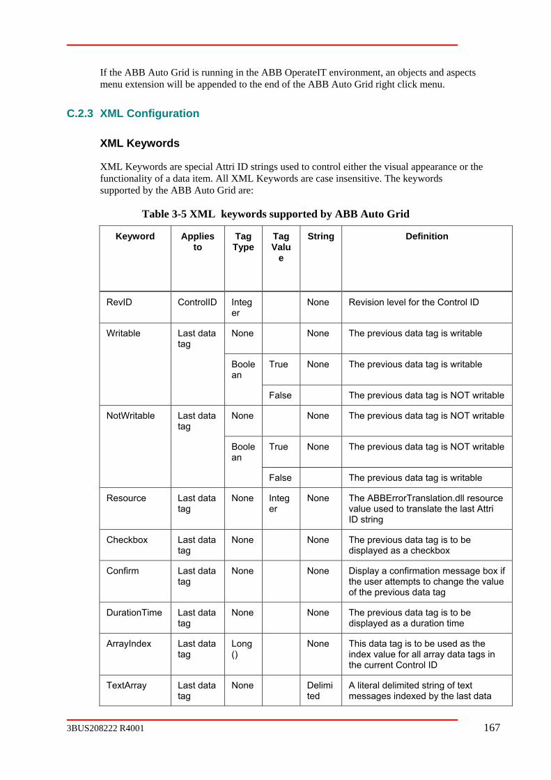
If the ABB Auto Grid is running in the ABB OperateIT environment, an objects and aspects menu extension will be appended to the end of the ABB Auto Grid right click menu.
C.2.3 XML Configuration
XML Keywords
XML Keywords are special Attri ID strings used to control either the visual appearance or the functionality of a data item. All XML Keywords are case insensitive. The keywords supported by the ABB Auto Grid are:
Table 3-5 XML keywords supported by ABB Auto Grid
Keyword Applies Tag Tag String Definition to Type Valu
e
RevID ControlID Integer
None Revision level for the Control ID
Writa g is writable ble Last data None None The previous data tatag
Boole True None The previous data tag is writable an
ble False The previous data tag is NOT writa
NotWritable Last ta None None The previous data tag is NOT writable datag
an
ritable Boole True None The previous data tag is NOT w
False The previous data tag is writable
Resource er
.dll resource value used to translate the last Attri
Last data tag
None Integ None The ABBErrorTranslation
ID string
Checkbox Last data None None The previous data tag is to be tag displayed as a checkbox
Confirm Last Display a confirmation message box if ge the value
data None None tag the user attempts to chan
of the previous data tag
DurationTime Last data tag
None None The previous data tag is to be displayed as a duration time
ArrayIndex Last data Long()
None This data tag is to be used as the index value for all array data tags in the current Control ID
tag
TextArray Last data tag
None Delimited
A literal delimited string of text messages indexed by the last data
3BUS208222 R4001 167

string tag
TextArrayResource
Last data tag
None Delimi A literal delimited string of numeric ted string
values used for language translation of TextArray
WriteTo Last data tag
Same as last data tag
Write the previous data tag changes to this tag
Example Configuration
The following example is from a real system configuration for a CD Overview display.
<Control ID="CD01OperGrd01"> <Tag ID="RevID"> <Attri ID="</Tag> <Tag ID="Reel Weight"> <Attri ID="Resource">8003</Attri> <Attri ID="Value">Svr02:PM03CD1:DPT.sr1men</Attri> <Attri ID="Resource">3443</Attri> <Attri ID="Rat <Attri ID="Res <Attri ID="Writable"></Attri> <Attri ID="Confirm"></Attri> <Attri ID="Variability">Svr02:PM03CD1:DPT.sr1var</Attri> <Attri ID="Resource">8006</Attri> <Attri ID="High Value">Svr02:PM03CD1:DPT.sr1hival</Attri> <Attri ID="Resource">8007</Attri> <Attri ID="Low Value">Svr02:PM03CD1:DPT.sr1loval</Attri> <Attri ID="Resource">8008</Attri> </Tag> <Tag ID="Reel Moisture"> <Attri ID="Resource">8004</Attri> <Attri ID="Value">Svr02:PM03CD1:DPT.sr2men</Attri> <Attri ID="Ratio">Svr02:PM03CD1:DPT.procent</Attri> <Attri ID="Variability">Svr02:PM03CD1:DPT.sr2var</Attri> <Attri ID="High Value">Svr02:PM03CD1:DPT.sr2hival</Attri> <Attri ID="Low Value">Svr02:PM03CD1:DPT.sr2loval</Attri> </Tag> <Tag ID="Combined Profile"> <Attri ID="Resource">8002</Attri> <Attri ID="Variability">Svr02:PM03CD1:DPT.sg2hrs</Attri> <Attri ID="High Value">Svr02:PM03CD1:DPT.ehrhih</Attri> <Attri ID="Low Value">Svr02:PM03CD1:DPT.ehrlow</Attri> </Tag> <Tag ID="Mapp <Attri ID="Resource">8005</Attri> <Attri ID="Variability">Svr02:PM03CD1:DPT.sg2act</Attri> <Attri ID="High Value">Svr02:PM03CD1:DPT.epfhih</Attri> <Attri ID="Low Value">Svr02:PM03CD1:DPT.epflow</Attri> </Tag> <Tag ID="Control <Attri ID="Resource">8009</Attri> <Attri ID="Value">Svr02:PM03CD1:DPT.ctlcnt</Attri> </Tag> <Tag ID="Setpoint Average"> <Attri ID="Resource">8010</Attri> <Attri ID="Value">Svr02:PM03CD1:DPT.actravg</Attri> <Attri ID="Variability">Svr02:PM03CD1:DPT.actrvar</Attri> <Attri ID="High Value">Svr02:PM03CD1:DPT.actrhival</Attri> <Attri ID="Low Value">Svr02:PM03CD1:DPT.actrloval</Attri> </Tag> <Tag ID="Feedback Average"> <Attri ID="Resource">8011</Attri> <Attri ID="Value">Svr02:PM03CD1:DPT.fdbkavg</Attri> <Attri ID="Variability">Svr02:PM03CD1:DPT.fdbkvar</Attri> <Attri ID="High Value">Svr02:PM03CD1:DPT.fdbkhival</Attri> <Attri ID="Low Value">Svr02:PM03CD1:DPT.fdbkloval</Attri> </Tag> </Control>
Value"> Svr02:PM03CDHSI:CD01OperGrd01Rev </Attri>
io">Svr02:PM03CD1:DPT.procmp</Attri> ource">3126</Attri>
ed Profile">
Counter">
168 3BUS208222 R4001
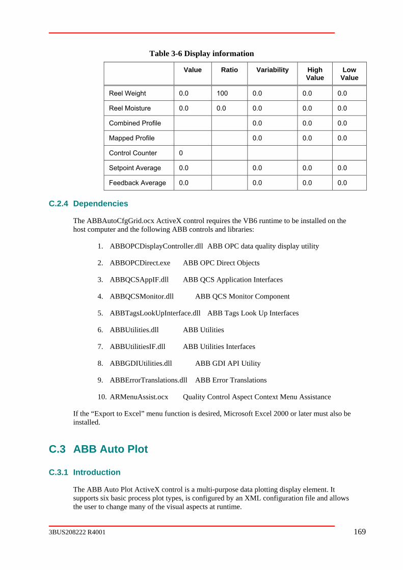
Table 3-6 Display information
Value Ratio Variability High Value
Low Value
Reel Weight 0.0 100 0.0 0.0 0.0
Reel Moisture 0.0 0.0 0.0 0.0 0.0
Combined Profile 0.0 0.0 0.0
Mapped Profile 0.0 0.0 0.0
Control Counter 0
Setpoint Average 0.0 0.0 0.0 0.0
Feedback Average 0.0 0.0 0.0 0.0
C.2.4 Dependencies
The ABBAutoCfgGrid.ocx ActiveX control requires the VB6 runtime to be installed on the host computer and the following ABB controls and libraries:
1. ABBOPCDisplayController.dll ABB OPC data quality display utility
2. ABBOPCDirect.exe ABB OPC Direct Objects
3. ABBQCSAppIF.dll ABB QCS Application Interfaces
4. ABBQCSMonitor.dll ABB QCS Monitor Component
5. ABBTagsLookUpInterface.dll ABB Tags Look Up Interfaces
6. ABBUtilities.dll ABB Utilities
7. ABBUtilitiesIF.dll ABB Utilities Interfaces
8. ABBGDIUtilities.dll ABB GDI API Utility
l Aspect Context Menu Assistance
the “Export to Excel” menu function is desired, Microsoft Excel 2000 or later must also be installed.
C.3 ABB Auto Plot
C.3.1 Introduction
The ABB Auto Plot ActiveX control is a multi-purpose data plotting display element. It supports six basic process plot types, is configured by an XML configuration file and allows the user to change many of the visual aspects at runtime.
9. ABBErrorTranslations.dll ABB Error Translations
10. ARMenuAssist.ocx Quality Contro
If
3BUS208222 R4001 169
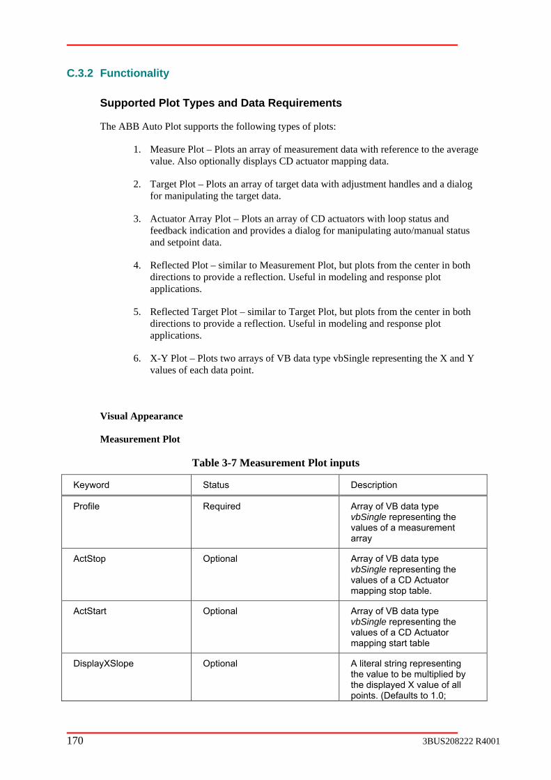
C.3.2 Functionality
Supported Plot Types and Data Requirements
The ABB Auto Plot supports the following types of plots:
1. Measure Plot – Plots an array of measurement data with reference to the average value. Also optionally displays CD actuator mapping data.
2. Target Plot – Plots an array of target data with adjustment handles and a dialog for manipulating the target data.
ator Array Plot – Plots an array of CD actuators with loop status and ack indication and provides a dialog for manipulating auto/manual status
and setpoint data.
4. Reflected Plot – similar to Measurement Plot, but plots from the center in both
5. Reflected Target Plot – similar to Target Plot, but plots from the center in both directions to provide a reflection. Useful in modeling and response plot applications.
6. X-Y Plot – Plots two arrays of VB data type vbSingle representing the X and Y values of each data point.
Visual Appearance
Measurement Plot
Table 3-7 Measurement Plot inputs
Keyword St Description
3. Actufeedb
directions to provide a reflection. Useful in modeling and response plot applications.
atus
Profile Required Array of VB data type vbSingle representing the values of a measurement array
ActSto Array of VB data type vbSingle representing the values of a CD Actuator mapping stop table.
p Optional
ActStart Optional Array of VB data type vbSingle representing the values of a CD Actuator mapping start table
DisplayXSlope Optional A literal string representing the value to be multiplied by the displayed X value of all points. (Defaults to 1.0;
170 3BUS208222 R4001

Optional)
DisplayXOffset Optional A literal string representing the value to be added to the displayed X value of all points. (Optional)
DisplayXName Optional A literal string representing the text to be used when displaying the X value (Optional)
DisplayYName Optional A literal string representing the text to be used when displaying the Y value (Optional)
LineStyle Optional Sets the current Tag Ids initial plot style “PointToPoint” OR “Rectangular” OR “Scatter”
AbsoluteY Optional If present, causes the
and low range values rather than using the high and low
values as offsets from erage.
measurement plot type to plot relative to the absolute high
rangethe av
Note: The va Disp pe * X + Display
XML:
<T re <Attri ID="Resource">8002</Attri> <Attri ID="Profile">Svr02:PM03CD1:SPT.epfpix</Attri> <Attri ID="Act PM03CD1:SPT.MapStartDataB <Attri ID="Act M03CD1:SPT.MapStopDataBox <Attri ID=" DisplayXOffset">32.75</Attri> <Attri ID=" DisplayXSlope">11 ri <Attri ID=" AbsoluteY"></Attr</Tag>
displayed X lue = layXSlo XOffset
ag ID="Moistu 1">
Start">Svr02:Stop">Svr02:P
ox</Attri> </Attri>
.5</Atti>
>
Snapshot Hide Tag ID
Time Stamp
Popup displays data under cursor
Left int d yed Rightm t displayed Average plot value Selected actuator mapping indication Deviation from average
most data po ispla ost data poin
DIALOG:
3BUS208222 R4001 171

The Measurement P urr
Target Plot
Keyword Status ption
lot does not c ently support a dialog.
Descri
Target uirReq ed Array of VB data type vbSingle representing the values of a target array
Fixed uir
et array are fixed
Req ed Array of VB data type vbBoolean indicating which values in the targ
NewTarget Required le for inputting user
changes to target values
Array of VB data type vbSing
NewFixe Required lean for inputting user
changes to fixed array
d Array of VB data type vbBoo
Target Required vbSingle representing the values of a target array
Array of VB data type
Associated XML:
<Tag ID="Target 1"> <Attri ID="Resource">8065</Attri> <Attri ID="Target">Svr02:PM03CD1:SPT.TargEditVal1</Attri> <Attri ID="NewTarget">Svr02:PM03CD1:SPT.TargEditVal1</Attri> <Attri ID="Fixed">Svr02:PM03CD1:SPT.TargEditFix1</Attri> <Attri ID="NewFixed">Svr02:PM03CD1:SPT.TargEditFix1</Attri> </
Tag>
DIALOG:
The target dialog ma ng the “Open Dialog” comcl e plot efa alo s listing however the user m oose to all target points by selecting the “Show all Points” option.
en dialog
y be opened byarea. By day ch
selectiult, the diview
mand button or double-only the selected target points, icking in th g open
Absolute values displayed Op
172 3BUS208222 R4001
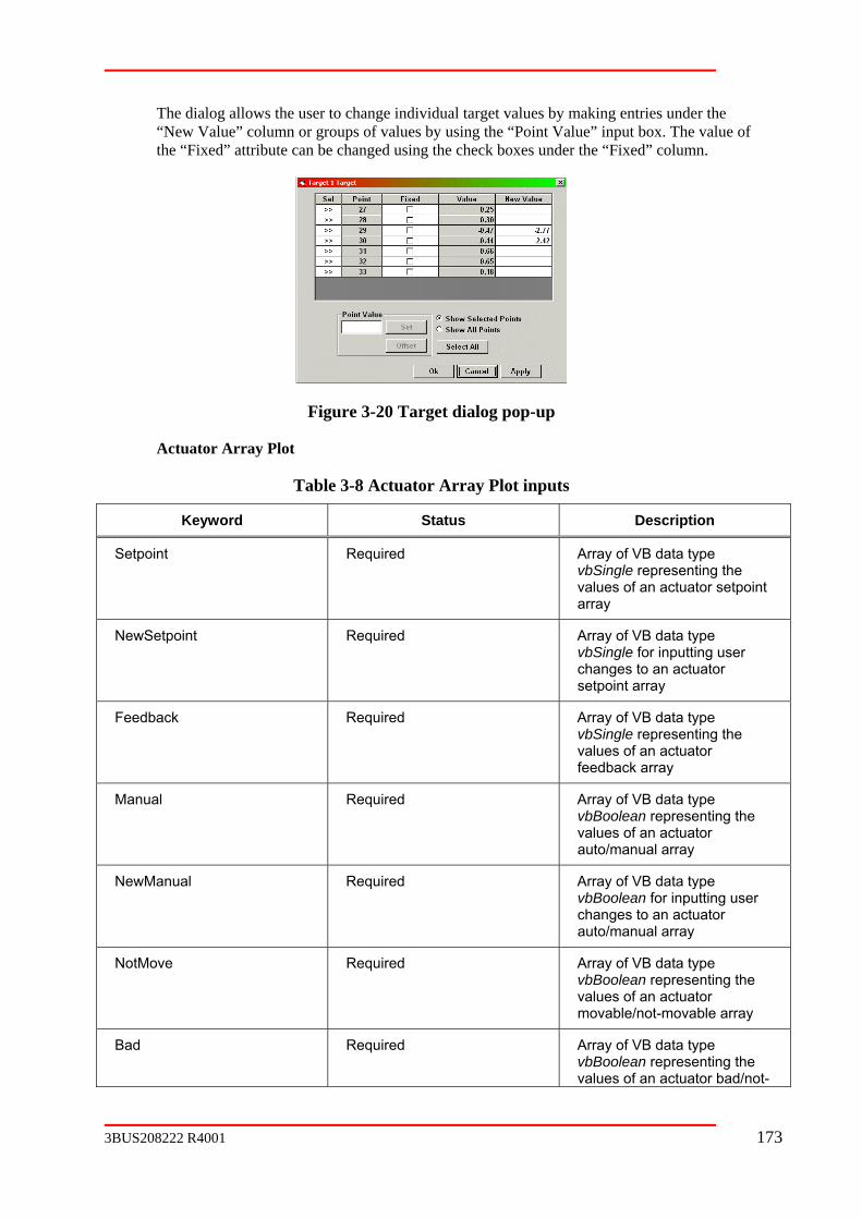
The dialog allows the user to change individual target values by making entries under the “New Value” colum using the “Point Value” input box. The value of the “Fixed” attribute can be changed using the check boxes under the “Fixed” column.
n or groups of values by
Figure 3-20 Target dialog pop-u
Actuator Array Plot
ble 3-8 Actuator Array Plot inp
ta
p
Ta uts
Keyword S tus Description
Setpoint Required vbSingle representing the values of an actuator setpoint array
Array of VB data type
NewSetpoint Required Array of VB data type vbSingle for inputting user changes to an actuator setpoint array
Feedba uir
dback array
ck Req ed Array of VB data type vbSingle representing the values of an actuator fee
Manual Array of VB data type vbBoolean representing the
Required
values of an actuator auto/manual array
NewManual Required
ator
Array of VB data type vbBoolean for inputting user changes to an actuauto/manual array
NotMove Required data type
rray
Array of VB vbBoolean representing the values of an actuator movable/not-movable a
Bad Required Array of VB data type vbBoolean representing the values of an actuator bad/not-
3BUS208222 R4001 173

bad array
BeginAc Opcontrol
t tional Scalar of vbLong indicating the first actuator on
EndAct Opator on control
tional Scalar of vbLong indicating the last actu
Actuato Op index into
the ActuatorStatusText of the
rStatus tional Array of VB data type vbLongrepresenting the
message indicating the statusof an actuator.
ActuatorStatusText Optional d by
ActuatorStatus
A literal delimited string of textmessages indexe
ActuatorStatusResource Optional delimited string of numeric values used for A literal
language translation of ActuatorStatusText
Feedba Opex into
ckStatus tional Array of VB data type vbLong representing the indthe FeedbackStatusText of the message indicating the status of actuator feedback
FeedbackStatusText Optional A literal delimited string of text messages indexed by FeedbackStatus
FeedbackStatusResource Op
ation of
tional A literal delimited string of numeric values used for language translFeedbackStatusText
Associated XML:
<Tag ID="Weight Profiler"> <Attri ID="Resource">8001</Attri> et 02: 1:SPT ttri ee 02: 1:SPT ttri <Attri ID="Man 2:PM03CD1:SPT.a at</Att <Attri ID="NewManual">Svr02:PM03CD1:SPT.stsend</Attri> ot 2:P :SPT. </At ad 03C .actb tri> New >Svr02:PM03CD1: end</At <Attri "Begi r02:PM03CD1:DPT t</Attri <Attri ID="EndAct">Svr02:PM03CD1:DPT.endact</Attri> </Tag>
<Attri ID="S<Attri ID="F
point">Svrdback">Svrual">Svr0
PM03CDPM03CD
.setpnt</A
.measmt</Actmanst
> > ri>
<Attri ID="N<Attri ID="B<Attri ID="
ID=
Move">Svr0">Svr02:PMSetpoint"nAct">Sv
M03CD1D1:SPT
actnotmoveadstat</AtSPT.sps.begac
tri> tri> >
Absolute values displayed
Open dialog
174 3BUS208222 R4001

DIALOG:
The actuator dialog may be opened by selecting the “Open Dialog” command double-clicking in the plot area.actuators; however the user may choose to view all actuators by selecting the “Show all Actuators” option.
T dialog allows the user to change individunder the “New SP” column or all selected actuainput box. The value of the auto/manual attribute can be changed using the check boxes under the “Man” column or all selected actuators can be changed by using the “Mode” buttons.
button or By default, the dialog opens listing only the selected
he ual actuator setpoint values by making entries tor setpoint values by using the “Setpoint”
Figure 3-21 Actuator profile modes and setpoints pop-up
XML with optional actuator and feedback status:
<Tag ID="SmartWeight Profiler"> <Attri ID="Setpoint">ActSvr01:PMAct01:Setpoint</Attri> <Attri ID="NewSetpoint">ActSvr01:PMAct01:NewSetpoint</Attri> <Attri ID="Feedback">ActSvr01:PMAct01:Feedback</Attri> <Attri ID="Manual">ActSvr01:PMAct01:Manual</Attri> <Attri ID="NewManual">ActSvr01:PMAct01:NewManual</Attri> <Attri ID="NotMove">ActSvr01:PMAct01:NotMove</Attri> <Attri ID="Bad">ActSvr01:PMAct01:Bad</Attri> <Attri ID="ActuatorStatus">ActSvr01:PMAct01:ActuatorStatus</Attri> <Attri ID="ActuatorStatusText">|OK|Not In Auto|Open Circuit|Short Circuit|Removed From Service| <Attri ID="ActuatorStatusResource">|8500|8501|8502|8503|8504|8505|</Attri> <Attri ID="FeedbackStatus">ActSvr01:PMAct01:FeedbackStatus</Attri>
ackStatusText">|OK|Invalid|Upper Hard Limit Reached|Lower Hard d|Upper Soft Limit Reached|Lower Soft Limit Reached|First Order
Bend Limit Reached|Second Order Bend Limit Reached|</Attri>
When th xed messages are added to the popup data display
Reflecte
In Limited Service|</Attri>
<Attri ID="Feedb Limit Reache
<AttriID="FeedbackStatusResource">|8510|8511|8512|8513|8514|8515|8516|8517|</Attri> </Tag>
e optional Actuator and Feedback status text messages are present, the inde and the Actuator dialog.
d Plot
3BUS208222 R4001 175

Table 3-9 Reflected Plot input
Key scription word Status De
Mprofile data type vbSingle representing the values of a reflected profile array
Required Array of VB
Associa
<Tag ID <Attri ID="Resource">6361</Attri> <Att</Tag>
ted XML:
="Mprofile 1">
ri ID="MProfile">Svr02:PM03CD1:SPT.rmodel</Attri>
Figure 3-22 Reflected Plot example
t does not currently support a dialog.
DIALOG:
The Reflected Plo
Reflected Target Plot
Table 3-10 Reflected Target Plot input
Keyword Status Description
Mtarget Required Array of VB data type vbSingle representing the values of a reflected target array
NewMTarget Required Array of VB data type vbSingle for inputting user changes to target values
Associated XML:
<Tag ID="MTarget 1"> <Attri ID="Resource">6361</Attri> <Attri ID=" MTarget ">Svr02:PM03CD1:SPT.rmodel</Attri>
rget">Svr02:PM03CD1:SPT.pmodel</Attri> <Attri ID="NewMTa</Tag>
176 3BUS208222 R4001

Figure 3-23 Reflected Target Plot example
DIALOG:
The reflected targ log” command button or double-clicking in the plot area. By default, the dialog opens listing only the selected target points, however the user may choose to view all target points by selecting the “Show all Points” option.
The dialog allows the user to change individual target values by“New Value” column or groups of values by using the “Point Value” input box. . The value
n be changed using the check boxes under the “Fixed” column.
et dialog may be opened by selecting the “Open Dia
making entries under the
of the “Fixed” attribute ca
Figure 3-24 Reflected Target Plot pop-up for individual points
X-Y Plot
Table 3-11 X-Y Plot inputs
Key ription word Status Desc
PlotX Required Array of VB data type vbSingle representing the X values of an X-Y plot
PlotY Required Array of VB data type vbSingle representing the Y values of an X-Y plot
DisplayXSlope Optional A literal string representing the value to be multiplied by
f all the displayed X value opoints. (Defaults to 1.0; Optional)
3BUS208222 R4001 177

Displa al string representing the value to be added to the displayed X value of all points. (Optional)
yXOffset Optional A liter
DisplayXName Optional A literal string representing the text to be used when displaying the X value (Optional)
Displa g e text to be used when
(Optional)
yYName Optional A literal string representinthdisplaying the Y value
LineSt Sets the current Tag Ids initial plot style “PointToPoint” OR “Rectangular” OR “Scatter”
yle Optional
AutoRange Optional If this keyword is present, the y
scale both the X and Y axis to keep all data points visible.
X-Y Plot will automaticall
Note: The displayed X value = XYDisplayXSlope * X + XYDisplayXOffset
Associated XML:
<Tag ID="Random 1"> D="Resource">6361</Attri> D=" PlotX">Svr02:PM03CD1:SPT.plotx</Attri>
<Attri I <Attri I <Attri ID=" PlotY">Svr02:PM03CD1:SPT.ploty</Attri> <Attri ID=" DisplayXOffset">32.75</Attri> <Attri ID=" DisplayXSlope">11.5</Attri> <Attri ID=" AutoRange"></Attri> </Tag>
Figure 3-25 X-Y plot example
DIALOG:
The X-Y Plot does not cur
In addition to the individual plot dialogs, the user has many more methods for controlling the appearance of the plots and retrieving data associated with each plot.
Right Click Menu
rently support a dialog.
User Interface
178 3BUS208222 R4001

Right clicking on the name of any plot will produce a message box displaying the source of the data used for the plot.
Figure 3-26 User Interface OPC Tag information message box
By right clicking in any plot area, the user is presented with a popup menu offering the options shown here.
Figure 3-27 Right click in plot area to get pop-up menu options
1. Select All will set all actuators and target points to be selected.
three different arrangements of the elements within the control. Any view may be changed during viewing, but only changes to the Engineer and Operator view will be persisted.
3. Export to Excel will produce an Excel workbook containing a tabulation of all data currently s been installed on the system.
n alternative method for capturing the data currently being displayed. The data is written to the Windows clipboard in a tab-
rm suitable for pasting into any application that supports the
scussed later.
2. Default View, Engineer View and Operator View provide a method for saving
being displayed provided Excel ha
4. Copy Data to Clipboard provides a
delimited foclipboard.
5. Display Options opens the “Display Options” dialog di
3BUS208222 R4001 179

6. Show Tool Tips provides a method for enabling or disabling the data popup thappears when the cursor touches a plot.
at
7. Help opens the compiled HTML help file for the control. (Currently not
If the ABB Auto Plot control is running in the ABB OperateIT environment, an objects and aspects menu extension will be appended to the end of the ABB Auto Plot menu.
Display
The can be changed at runtime to provide a more usable data presentation. The following screen captures illustrate the options available for each type of plot.
supported)
Options Dialog
Display Options Dialog offers the user a variety of visual settings that
Figure 3-28 Measurement plot display options
Figure 3-29 Target Plot Display Options
180 3BUS208222 R4001

Figure 3-30 Actuator Array Plot Display Options
Figure 3-31 Reflected Plot Display Options
Figure 3-32 Reflected Target Plot Display Options
3BUS208222 R4001 181

Figure 3-33 X-Y Plot Display Options
lots, target plots and actuator plots can be configured to include a ruler in the ment and display type ticks only or ticks with numbers, are
plot.
Rulers
Measurement pplot area. The ruler tick increconfigured from the display options dialog for each
Zooming and Scrolling
t he
and
click drag release
The plots displayed can be expanded horizontally to provide more detail by pressing the lefmouse button in the plot area and dragging left or right to enclose an area to be expanded. Tscroll bar beneath the plot represents the relative position and size of the expanded viewcan be used to scroll the view window left or right.
Ticks with numbers Tick increment = 20
Ticks without numbers Tick increment = 20
182 3BUS208222 R4001
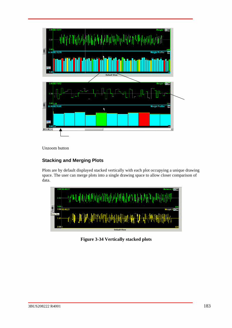
Unzoom button
Stacking and Merging Plots
Plots are by default displayed stacked vertically with each plot occupying a unique drawing pace. The user can merge plots into a single drawing space to allow closer comparison of
data. s
Figure 3-34 Vertically stacked plots
3BUS208222 R4001 183

Figure 3-35 Merging Plots
Rearranging Plots
Plots can be rearranged vertically by pressing the left mouse button on the name of a plot andragging it up or down to a new location.
d
C.3.3 iguration
XML ords
ID strings used to control either the visual appearance or the . XML Keywords are case insensitive. The keywords supported by
-36 Keywords for all plot types
g String Definition
XML Conf
Keyw
XML Keywords are special Attrifunctionality of a data itemthe ABB Auto Plot are:
Figure 3
Keyword Applies to Ta
RevID ControlID Integer None Revision level for the Control ID
NewWindow Current Tag ID None None
Create a new plot window with the current Tag ID
Merged Current Tag ID None None Make the plots in the current window
merged. This keyword should follow
click release drag
184 3BUS208222 R4001
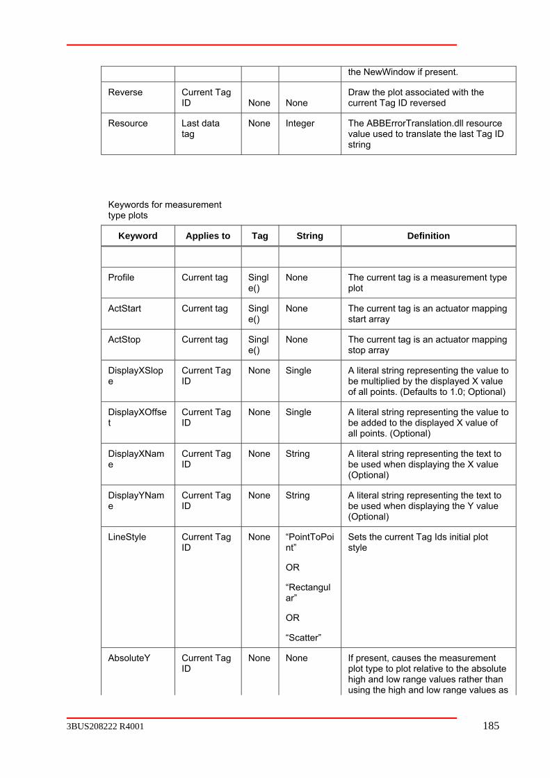
the NewWindow if present.
Reverse Current Tag ID None None
Draw the plot associated with the current Tag ID reversed
Resource Last data None Integer The ABBErrorTranslation.dll resource value used to translate the last Tag ID string
tag
Keywords for meastype plots
urement
Keyword Applies to Tag String Definition
Profile Current tag Singl None()
e The current tag is a measurement type plot
ActStart Current tag Single()
None The current tag is an actuator mapping start array
ActStop Current tag Singl None The currene()
t tag is an actuator mapping stop array
DisplayXSlope
Current Tag ID
None Single
of a
A literal string representing the value to be multiplied by the displayed X value
ll points. (Defaults to 1.0; Optional)
DisplayXOffset
Current Tag ID
None
all points. (Optional)
Single A literal string representing the value to be added to the displayed X value of
Displae ID
(Opt
yXNam Current Tag None String A literal string representing the text to be used when displaying the X value
ional)
DisplayYName
Current TagID
(Opt
None String A literal string representing the text to be used when displaying the Y value
ional)
LineStyle Current Tag ID
None “PointToPoint”
OR
ar”
Sets the current Tag Ids initial plot st
“Rectangul
OR
“Scatter”
yle
AbsoluteY Current Tag ID
None None If present, causes the measurement
high and low range values rather than plot type to plot relative to the absolute
using the high and low range values as
3BUS208222 R4001 185
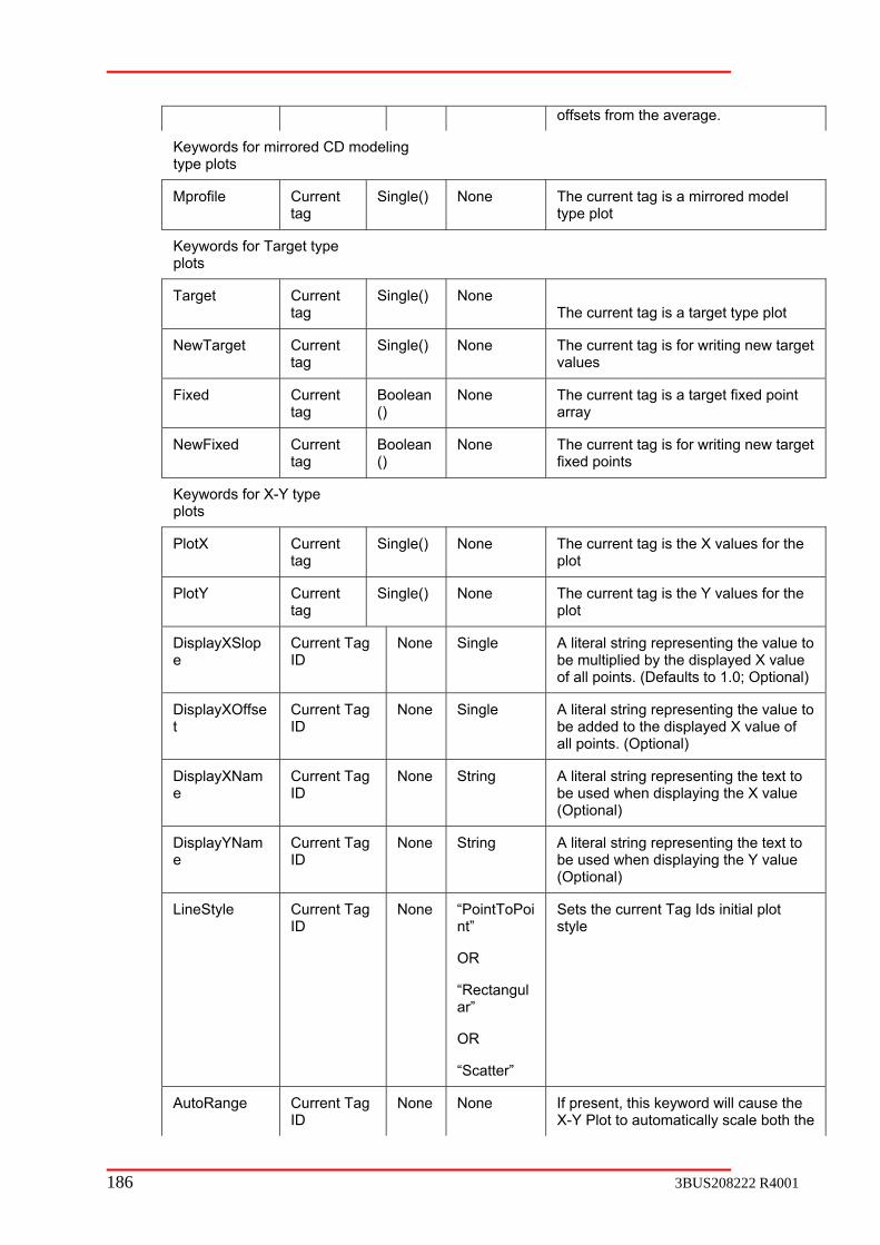
offsets from the average.
Keywords for mirrored CD modeling type plots
None The current tag is a mirrored model type plot
Mprofile Current tag
Single()
Keywords for Taplots
rget type
Target Current tag
Single() None The current tag is a target type plot
NewTarget Current Single() None The current tag is for writing newtag
target values
Fixed Current tag
Boolean()
None The current tag is a target fixed point array
NewFixed Current tag () fixed points
Boolean None The current tag is for writing new target
Keywords for X-Y type plots
PlotX Current tag
Single() None The current tag is the X values for the plot
PlotY Current tag
Single() None The current tag is the Y values for the plot
DisplayXSlope
Current Tag ID
None Single A literal string representing the value to be multiplied by the displayed X value of all points. (Defaults to 1.0; Optional)
DisplayXOffset
Current Tag ID
None Single A literal string representing the value to be added to the displayed X value of all points. (Optional)
DisplayXName
Current Tag ID
None String A literal string representing the text to be used when displaying the X value (Optional)
DisplayYNam Current Tag ID
None String A literal string representing the text to be used when displaying the Y value (Optional)
e
LineStyle Current Tag ID
None “PointToPoint”
Sets the current Tag Ids initial style
OR
“Rectangul
OR
“Scatter”
plot
ar”
AutoRange Current Tag ID
None None If present, this keyword will cause the X-Y Plot to automatically scale both the
186 3BUS208222 R4001

X and Y axis to keep all data points visible.
Keywords for mirrored CD target type plots
MTarget Current tag
Single() None The current tag is a mirrored ttype plot
arget
NewMTarget Current Single() None The current tag is for writing new mirrored target values tag
MFixed Current Boolean None tag ()
The current tag is a mirrored target fixed point array
NewMFixed Current tag
Boolean()
None The current tag is for writing new mirrored target fixed points
Keywords for CD actuator type plots
Setpoint Current tag
Single() None The current tag is an actuator setpoint array
NewSetpoint Current Single() None The current tag is for writing new tag actuator setpoint values
Feedback Current tag feedback array
Single() None The current tag is a measurement
Manual Current tag
Boolean()
None The current tag is the actuator in manual status array
NewManual Current tag
Boolean None The current tag is for writing new () actuator manual values
NotMove Current tag
Boolean()
None The current tag is the actuator not movable status array
Bad Current Boolean None The currentag ()
t tag is the actuator bad status array
BeginAct Current tag
Integer None The current tag is the first actuator in the active control range
EndAct Current tag
Integer None The current tag is the last actuator in the active control range
ActuatorStatus
Current tag
Long() None The current tag is the index into the ActuatorStatusText of the message indicating the status of an actuator
ActuatorStatusText
delimited string of text es indexed by ActuatorStatus
ActuatorStatus
None Delimited string
A literal messag
ActuatorStatusResource
ActuatorStatus
None Delimited string
A literal delimited string of numeric values used for language translation of
ext ActuatorStatusT
Feedbus
ent Long() None The current tag is the index into the FeedbackStatusText of the message indicating the status of an actuator
ackStat Currtag
3BUS208222 R4001 187
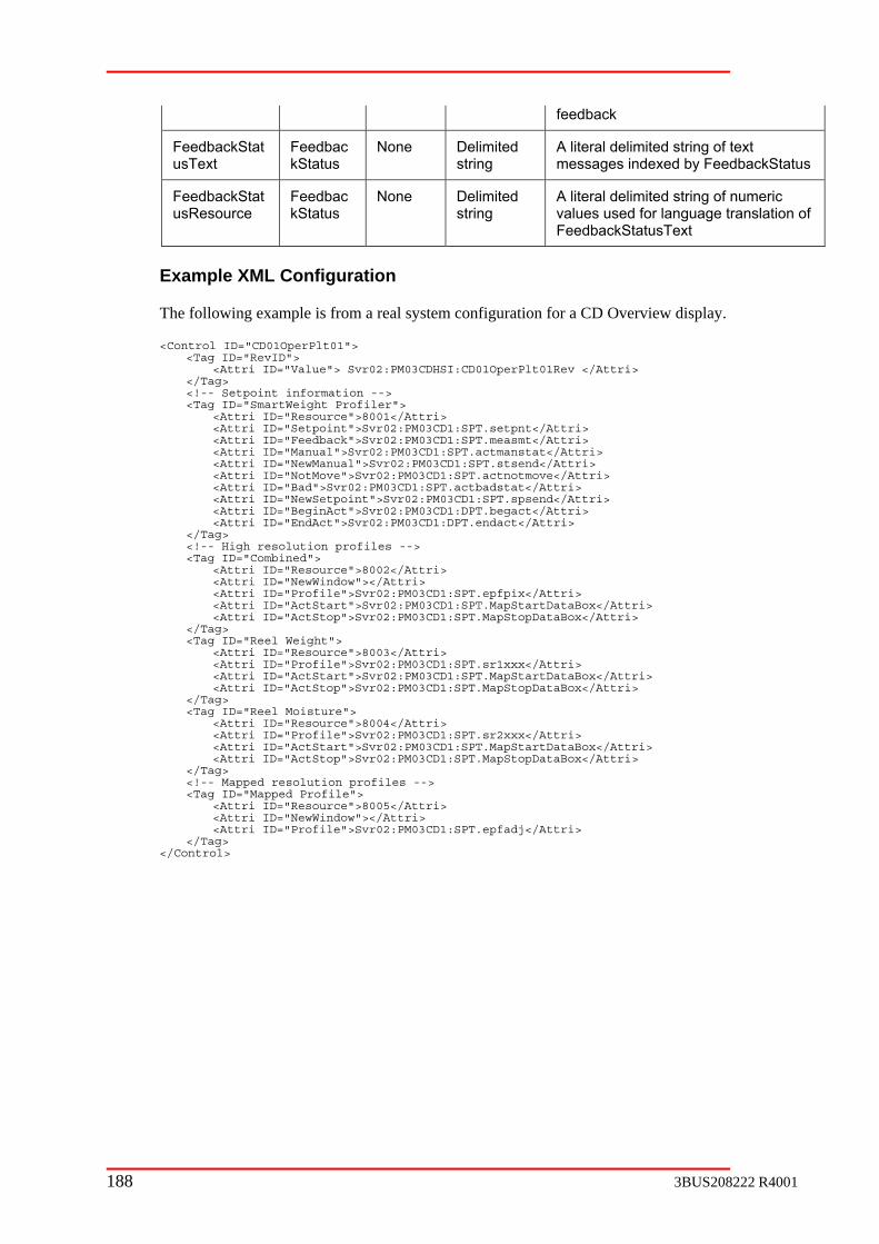
feedback
FeedbackStatusText kStatus string messages indexed by FeedbackS
Feedbac None Delimited A literal delimited string of text tatus
FeedbackStat Feedbac None Delimited string
A literal delimited string of numeric values used for language translation of FeedbackStatusText
usResource kStatus
Example XML Configuration
splay.
<Tag ID="SmartWeight Profiler"> ">8001</Attri> ">Svr02:PM03CD1:SPT.setpnt</Attri> <Attri ID="Feedback">Svr02:PM03CD1:SPT.measmt</Attri> 3CD1:SPT.actmanstat</Attri> PM03CD1:SPT.stsend</Attri> <Attri ID="NotMove">Svr02:PM03CD1:SPT.actnotmove</Attri> <Attri ID="Bad">Svr02:PM03CD1:SPT.actbadstat</Attri>
ewSetpoint">Svr02:PM03CD1:SPT.spsend</Attri> eginAct">Svr02:PM03CD1:DPT.begact</Attri>
<Attri ID="EndAct">Svr02:PM03CD1:DPT.endact</Attri>
<Attri ID="NewWindow"></Attri> <Attri ID="Profile">Svr02:PM03CD1:SPT.epfpix</Attri> <Attri ID="ActStart">Svr02:PM03CD1:SPT.MapStartDataBox</Attri> <Attri ID="ActStop">Svr02:PM03CD1:SPT.MapStopDataBox</Attri> </Tag> <Tag ID="Reel Weight"> <Attri ID="Resource">8003</Attri> <Attri ID="Profile">Svr02:PM03CD1:SPT.sr1xxx</Attri> <Attri ID="ActStart">Svr02:PM03CD1:SPT.MapStartDataBox</Attri> <Attri ID="ActStop">Svr02:PM03CD1:SPT.MapStopDataBox</Attri> </Tag> <Tag ID="Reel Moisture"> <Attri ID="Resource">8004</Attri> <Attri ID="Profile">Svr02:PM03CD1:SPT.sr2xxx</Attri> <Attri ID="ActStart">Svr02:PM03CD1:SPT.MapStartDataBox</Attri> <At </Tag> <!-- Mapped resolution profiles -->
ID="Profile">Svr02:PM03CD1:SPT.epfadj</Attri> </Tag> </Control>
The following example is from a real system configuration for a CD Overview di
<Control ID="CD01OperPlt01"> <Tag ID="RevID"> <Attri ID="Value"> Svr02:PM03CDHSI:CD01OperPlt01Rev </Attri> </Tag> <!-- Setpoint information -->
<Attri ID="Resource<Attri ID="Setpoint
<Attri ID="Manual">Svr02:PM0<Attri ID="NewManual">Svr02:
<Attri ID="N <Attri ID="B
</Tag> <!-- High resolution profiles --> <Tag ID="Combined"> <Attri ID="Resource">8002</Attri>
tri ID="ActStop">Svr02:PM03CD1:SPT.MapStopDataBox</Attri>
<Tag ID="Mapped Profile"> <Attri ID="Resource">8005</Attri> <Attri ID="NewWindow"></Attri> <Attri
188 3BUS208222 R4001

Figure 3-37 ABB Auto Plot example
C.3.4 Dependencies
The ABBAutoCfgGrid.ocx ActiveX control requihost computer and th ing ls an
1. ABBOPCDisplayController.dll ABB
2. ABBOPCDirect.exe ABB Direct Objects
C .dll ABB tion Interfaces
4. ABBQC onitor.dl BB
5. ABBTagsLookUpInterface.dll ABB
6. ABBUtilities.dll ABB
7. ABBUtil iesIF.dll BB
8. ABBGDIUtilities.dll ABB
9. ABBErrorTranslations.dll ABB Error Translations
10. ARMenuAssist.ocx Quality Control Aspect Context Menu
x ABB Multi Plot
12. ABBMultiPlotIF.dll ABB Multi Plot Interfaces
res the VB6 runtime to be installed on the d libraries: e follow ABB contro
OPC data quality display utility
OPC
3. ABBQ SAppIF QCS Applica
SM l A QCS Monitor Component
Tags Look Up Interfaces
Utilities
it A Utilities Interfaces
GDI API Utility
Assistance
11. ABBMultiPlotCtl.oc
3BUS208222 R4001 189

If the “Export to Excel” menu function is deinstalled.
ABB Command Button
Introduction
The “ABB Command Button” ActiveX control name, and “ABBComdButtons.ocx” as Activ
This Acthe display at run time.
Functionality
Basic XML Structure
<Tag ID="Map Orientation"> <Attri ID="Resource">8020</Attri> <Attri ID="Request">Svr02:PM03CD1: <Attri ID="Writable"></Attri> <Attri ID="State">Svr02:PM03CD1:DPT.ac <Attri ID="Confirm"></Attri> <Attri ID="ConfirmRes">1111</Attri> </Tag>
Properties
DisplayType
The DisplayType property has two value can select: “1 – ndtVerical” or “2 – ndtHorizontal”
sired, Microsoft Excel 2000 or later must also be
C.4
C.4.1
uses “ABB Command Button” as registered eX control name.
tiveX control is XML configurable and allow user to change some visual aspects of
C.4.2
DPT.actdir</Attri>
tdir</Attri>
C.4.3
Figure 3-38 Display Type
Figure 3-39 DisplayType=“1 – ndtVerical”
Figure 3-40 DisplayType=”2 – ndtHorizontal”
190 3BUS208222 R4001

C.4.4
mand buttons that show on the control in design time. Once it got connection with server, the XML file on the HSI server will drive
mmand buttons is determined by the number of the “Tag ID” in the XML, except “Tag ID” equal to “RevID” and “Title”. For example, in the Example of XML File
”, control will display four command button (the
NumberOfButtons
This property will determine the number of com
the number of buttons that displayed on the control.
The number of co
section, there are 6 “Tag ID”: “RevID”, “Map Orientation”, “AutoMap”, “Constant Map“Apply Width”, and “title”, the ActiveXreserved “RevID” and “title” are not counted).
Figure 3-41 Buttons resulting from XML file implementation
When the number of the command button increase or decrease, the whole control size of ll not change, but the size of inside each command button will be
C.4.5
of this tag changes, the ABB Command ActiveX control will delete the group, reconnect to the server, and rebuild this command button ActiveX control
<Tag ID="RevID">
C.4.6
es will be used to open a context sensitive
ce Name</Attri>
“ABB Command Button” wichanged.
XML Key Word
RevID
When the valuecurrent OPCbased on the XML file from the server.
<Attri ID="Value">Svr02:PM03CDHSI:CD01MappCmd01Rev</Attri> </Tag>
HelpID
This keyword specified a string ID that used by ABBHelpUtility.dll to retrieve the associated help file name and contextID from an INI file. If “HelpFileName” property is empty or is null, the content of “HelpID” in XML file will be used, otherwise the values of “HelpFileName” and “HelpContextID” propertihelp file. If “HelpFileName” property is null and a “HelpID” entry does not exist in XML file, the “Help” option in right click popup menu will be disabled.
<!—Context Help ID --> <Tag ID="HelpID"> <Attri ID="Value">Help Referen</Tag>
3BUS208222 R4001 191
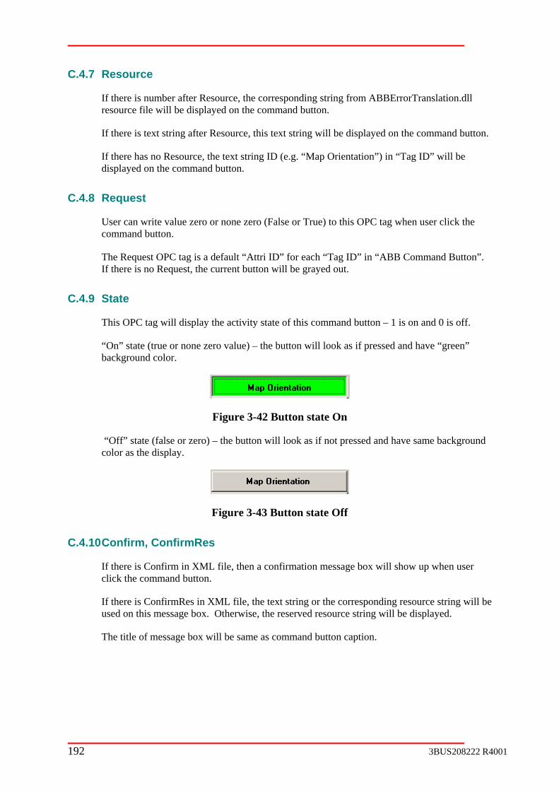
C.4.7
If there is number after Resource, the corresponding string from ABBErrorTranslation.dll
If there is text string after Resource, this text string will be displayed on the command button.
e text string ID (e.g. “Map Orientation”) in “Tag ID” will be displayed on the command button.
C.4.8
ero (False or True) to this OPC tag when user click the command button.
The Request OPC tag is a default “Attri ID” for each “Tag ID” in “ABB Command Button”.
C.4.9 State
This OP a d e of this command button – 1 is on and 0 is off.
“On” state (true or none zero value) – the button will look as if pressed and have “green” background color.
Resource
resource file will be displayed on the command button.
If there has no Resource, th
Request
User can write value zero or none z
If there is no Request, the current button will be grayed out.
C t g will isplay the activity stat
Figure 3-42 Button state On
“Off” stor as
ate (false or zero) – the button will look as if not pressed and have same background the display. col
Figure 3-43 Button state Off
C.4.10 Confirm, ConfirmRes
re i sage box will show up when user mand button.
If there is ConfirmRes in XML file, the text string or the corresponding resource string will be used on t ge box. Otherwise, the reserved resource string will be displayed.
The title of mes
If theclick the com
s Confirm in XML file, then a confirmation mes
his messa
sage box will be same as command button caption.
192 3BUS208222 R4001
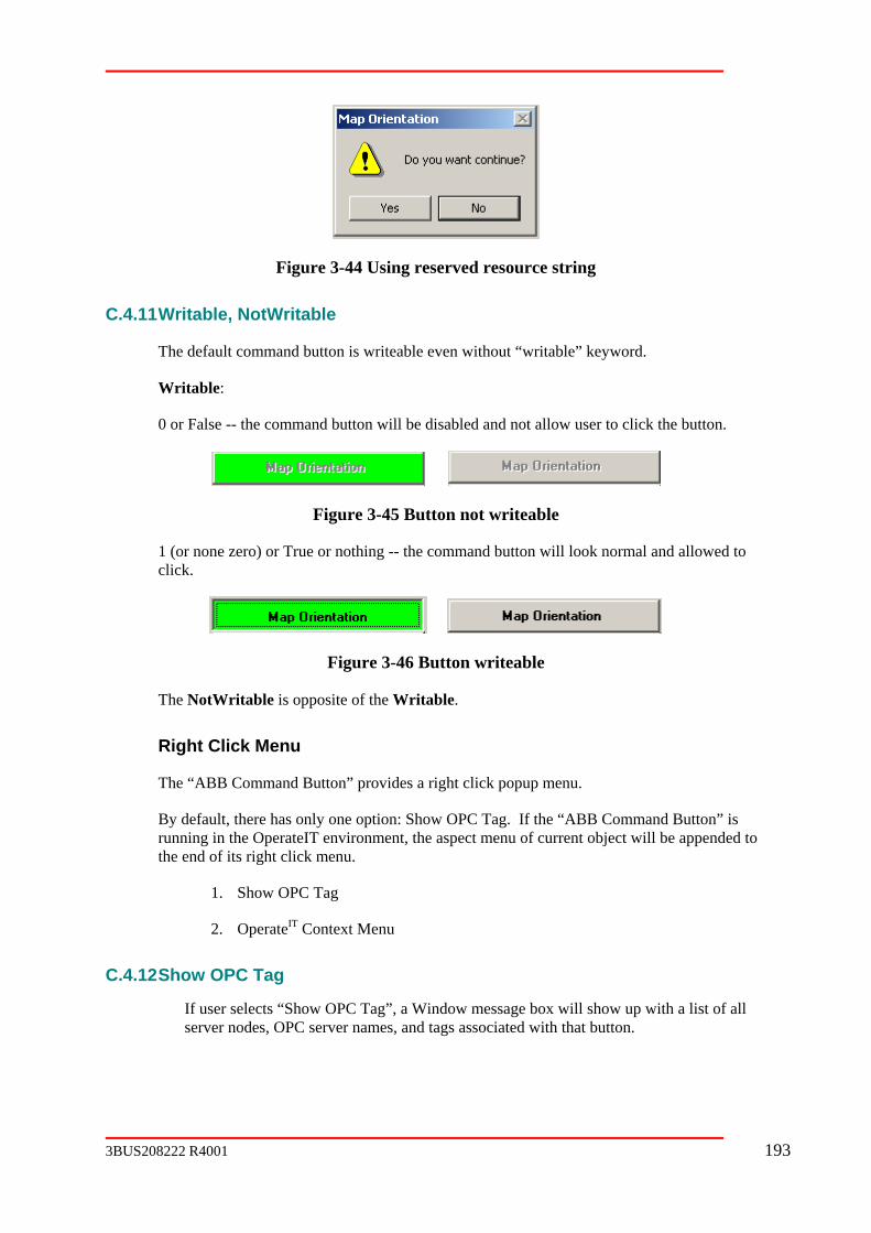
Figur
, NotWritable
The default command button is writeable even without “writable” keyword.
Writabl
0 or False -- the command button will be disabled and not allow user to click the button.
e 3-44 Using reserved resource string
C.4.11 Writable
e:
Figure 3-45 Button not writeable
or nothing -- the command but1 (or none zero) or True ton will look normal and allowed to click.
Figure 3-46 Button writeable
The NotWritable is opposite of the Writable.
Right Click Menu
The “ABB Command Button” provides a right click popup menu.
By default, there has only one option: Show OPC Tag. If the “ABB Command Button” is running in the OperateIT environment, the aspect menu of current object will be appended to the end of its right click menu.
1. Show OPC Tag
2. OperateIT Context Menu
C.4.12 Show OPC Tag
If user selects “Show OPC Tag”, a Window message box will show up with a list of all server nodes, OPC server names, and tags associated with that button.
3BUS208222 R4001 193

Figure 3-47 Sh
The message b n”
ow OPC tag gives server names and tags associated with button
ox title will be: the current command button caption + “OPC Tag Informatio
194 3BUS208222 R4001

C.4.13 XM
Keyword Applies Definition
L Keywords
to Tag Type
Tag Value
(Not Case Sensitive)
RevID ControlID Int ol ID eger Revision level for the Contr
HelpID C Context Help ID ontrolID String
Request Last datatag
Written tag
State Last data tag
Display tag
Confirm Last data tag
No ser attempts to change the value
ne Display a confirmation message box if the u
ConfirmRes
Last data tag
string The string that will appear on the confirmation message box.
text string Using this text string.
number string
Using corresponding string from ABBErrorTranslation.dll resource.
none Using default string from ABBErrorTranslation.dll resource
Writab e The previous data tag is writable le Last data tag
Non
(True)
s data tag is writable Boolea non zero The previoun
writable 0 (False) The previous data tag is NOT
NotWritable
The previous data tag is NOT writable Last data tag
None
zero(True)
able Boolea non The previous data tag is NOT writn
0 (False) The previous data tag is writable
title ControlID String Indicate title.
3BUS208222 R4001 195

title Text string Display this text string for the
string
m ABBErrorTranslation.dll resource.
Number Display corresponding string fro
Resource String caption for command button
t string Display this text string on the command button Tex
Display corresponding string from ABBErrorTranslation.dll resource.
Number string
None Using the keyword of this "Tag ID".
C.4.14 Examp
ntrol <Tag ID="RevID">
</Ta <!—Context Help ID --> <Tag <Attri ID="Value">Help Reference Name</Attri> </Ta <Tag ID="M <Attri <Attri <Attri </Tag> <Tag ID="A <Attri <Attri <Attri </Tag> <Tag ID="C ta <Attri <Attri <Attri </Tag> <Tag ID="A <Attri <Attri ri> </Tag> <Tag ID="title"> <Attri </Tag> </Control>
C.5 ABB Indi
C.5.1 Introduction
The “ABB Indicat X coname, and “ABBIn ctive
The ABB Indicator Control is a message sages) that affect operations of controls. It uses ervice to retrieve tags information from the server. If there are no existing conditions, a predefined message (defined on tags XML files on server PC) will show to indicate there are no messages. Each condition message’s foreground and background color can be configurable in tag XML file.
le of XML File
ID="CD01MappCmd01"> <Co
<Attri ID="Value">Svr02:PM03CDHSI:CD01MappCmd01Rev</Attri> g>
ID="HelpID">
g> ap Orientation"> ID="request">Svr02:PM03CD1:DPT.actdir</Attri> ID="Writable"></Attri> ID="state">Svr02:PM03CD1:DPT.actdir</Attri>
utoMap"> ID="request">Svr02:PM03CD1:DPT.autmap</Attri> ID="notWritable">Svr02:PM03CD1:DPT.usemap</Attri> ID="state">Svr02:PM03CD1:DPT.autmap</Attri>
ons nt Map"> ID="request">Svr02:PM03CD1:DPT.UseMap</Attri> ID="notWritable">Svr02:PM03CD1:DPT.autmap</Attri> ID="state">Svr02:PM03CD1:DPT.UseMap</Attri>
pply Width"> ID="request">Svr02:PM03CD1:DPT.acspset</Attri> ID="Writable"></Att
ID="Value">Mapping Options</Attri>
cator Control
or Control” Active ntrol uses “ABB Indicator Control” as registered dicator.ocx” as A X control file name.
window which displays conditions (string mesTag Lookup S
196 3BUS208222 R4001

C.5.2 Functionality
Figure 3-48 CD Overview Indicator messages
Basic XML
<Control ID="IndictorName"> <Tag ID="RevI <Attri ID="Value">Svr01:PM03CDHSI:CD01OperInd01Rev</Attri>
t Help ID --> <Attri ID="ReverseFlag"></Attri> </Tag> <Tag </Tag> <Tag D="title"> <Attri ID="Value">CD Overview Indicators</Attri> </Ta</Control>
C.5.3 XML Key Word
C.5.4 RevID
When the value of this tag changes, the ABB Indicator control will delete the current OPC group, and recre
<Tag ID="RevID"> <Attri ID="Value">S</Tag>
C.5.5 HelpID
This keyword specified a string ID that used help file name and conte pty or is null, the content of “HelpID” in XML file will be used, otherwise the values of “HelpFileName” and “Hhelp file. If “HelpFileNfile, the “Help” option in opup menu will be disabled.
<Tag </Ta
Structure
D">
</Tag> <!—Contex
<Tag ID="HelpID"> <Attri ID="Value">Help Reference Name</Attri> </Tag> <Tag ID="Control Suspended"> <Attri ID="Resource">8013</Attri> <Attri ID="Value">Svr02:PM03CD1:DPT.waitflg</Attri> <Attri ID="IndBackColor">2</Attri>
ID="NoInd"> <Attri ID="Resource">8019</Attri>
I
g>
ate OPC group according to the current data from the server.
vr01:PM03CDHSI:CD01OperInd01Rev</Attri>
by ABBHelpUtility.dll to retrieve the associated xtID from an INI file. If “HelpFileName” property is em
elpContextID” properties will be used to open a context sensitive ame” property is null and a “HelpID” entry does not exist in XML right click p
<!—Context Help ID --> ID="HelpID"> <Attri ID="Value">Help Reference Name</Attri> g>
3BUS208222 R4001 197

C.5.6 Resource
If the content of Resource is a number, the corresponding string will be retrieved from ABBErrorTranslation.dll, and displayed on the indicator control if there is a condition.
If there is no Resource keyword, the text string of the Tag ID (Control Suspended) will be used.
C.5.7 Value
The content of Value is the actual tags information for each condition.
C.5.8 IndBackColor,
Those two keyw ptional, they are defined as background and foreground color for each message. If those keycolor setting from ReadO
<Attri ID="IndBackColo<Attri ID="IndForeColo
The color scheme is defined below:
0 ---- Black
1 ---- Red
2 ---- Green
3 ---- Yellow
4 --
5 --
6 ---- Cy
7 ---- W
8 ---- vbButtonFace (light gray)
9 ---- vbInactiveTitleBar
10 ---- vbButtonText (black)
Wind
C.5.9 ReverseFlag
This keyword te
<Tag ID="Control Suspe <Attri ID="Value">S <Attri ID="ReverseF</Tag>
IndForeColor
ords are owords are omitted in XML file, the Indictor control will use the
nlyBackColor and ReadOnlyForeColor properties.
r">2</Attri> r">0</Attri>
-- Blue
-- Magenta
an
hite
11 ---- vb owBackground (white)
lls the condition will be reversed.
nded"> vr02:PM03CD1:DPT.waitflg</Attri> lag"></Attri>
198 3BUS208222 R4001

In this example, if waitf Indicator control, otherwise, there is no condition message.
Right Click Menu
The Indicator control pr
default, there are two options: Show OPC Tag, and Help. If the Indicator control is runn ed to the
C.5.10 Show OPC Tag
If there ed out), it will enabled whenever there is a condition message displayed. If user selects “Show OPC Tag”, a Window message box will show up with a list of all server nodes, OPC server names, and tags associated with that condition m
C.5.11 Example of XML File
<Control ID="CD<Tag ID="RevID" <Attri ID="</Tag> <!—Context Help<Tag ID="HelpID <Attri ID="Value">Help Reference Name</Attri> </Tag> <Tag ID="Control Suspended"> <Attri ID=" <Attri ID=" <Attri ID=" <Attri ID="</Tag> <Tag ID="Control Not Available"> <Att ce">8014</Attri> <Att <Attri ID="</Tag> <Tag ID="Contro <Attri ID=" <Attri ID=" <Attri ID="IndBackColor">5</Attri> </Tag> <Tag ID="Actuator in Local"> <Attri <Att DPT.localflg</Attri> </Tag> <Tag ID <Attri <Attri </Tag> <Tag ID="Excessive MD Variation"> <Att <Attri </Tag> <Tag ID <Attri ID="Resource">6310</Attri> <Attri ID="Value">Svr02:PM03CD1:DPT.sheetb</Attri> </Tag> <Tag ID="Bump Test In Progress"> <Attri ID="Resource">8018</Attri> <Att .BumpInProgress</Attri> </Tag> <Tag ID="Home <Attri ID=</Tag> <Tag ID="Far Edge Offset"> <Attri ID="Value">Svr02:PM03CD1:DPT.EdgCtrlEndOffsEnab</Attri> </Tag> <Tag ID="NoInd"> <Att rce">8019</Attri> </Tag>
lg = False, the condition message will be showed on the
ovides a right click popup menu.
Bying in the OperateIT environment, the aspect menu of current object will be append
end of its right click menu.
is no condition message, the “Show OPC Tag” option will be disabled (gray
essage.
01OperInd01"> > alue">Svr01:PM03CDHSI:CD01OperInd01Rev</Attri> V
ID --> ">
Resource">8013</Attri> Value">Svr02:PM03CD1:DPT.waitflg</Attri> IndBackColor">2</Attri> ReverseFlag"></Attri>
ri ID="Resourri ID="Value">Svr02:PM03CD1:DPT.inopflg</Attri>
IndBackColor">3</Attri>
l Aborted"> Resource">8015</Attri> Value">Svr02:PM03CD1:DPT.abortflg</Attri>
ID="Resource">7397</Attri> ri ID="Value">Svr02:PM03CD1:
="Excessive CD Variation"> ID="Resource">8016</Attri> ID="Value">Svr02:PM03CD1:DPT.exvcdv</Attri>
ri ID="Resource">8017</Attri> ID="Value">Svr02:PM03CD1:DPT.exvmdv</Attri>
="Sheet Break">
ri ID="Value">Svr02:PM03CD1:DPT
Edge Offset"> "Value">Svr02:PM03CD1:DPT.EdgCtrlBeginOffsEnab</Attri>
ri ID="Resou
3BUS208222 R4001 199

<Tag ID="title"> <Attri ID="Value">CD Color Indicate</Attri>
g> ntrol>
</Ta</Co
C.6 ABB CD Mapping Control
C.6.1 Introduction
The “ABB CD Mapping ActiveX Control” ActiveX uses “ABB CD Mapping ActiveX Control” as regi ontrol file name.
This ActiveX control is special designed for CD Mapping display. It is XML configurable.
C.6.2 Functionality
stered name, and “ABBCDMapping.ocx” as ActiveX c
Figure 3-49 CD Mapping ActiveX control
C.6.3 RevID
When th eX control will delete the current OPC gro tiveX control based on the XML file from
<Tag ID="RevID"
</Ta
e value of this tag changes, the ABB CD Mapping Activp, reconnect to the server, and resetting this Acu
the server.
>
<Attri ID="Value">Svr02:PM03CDHSI:CD01MappPix01Rev</Attri>
g>
200 3BUS208222 R4001

C.6.4
This key ified a string ID that used by ABBHelpUtility.dll to retrieve the associated help file name null, the conten“HelpFileNamhelp file. If “H s not exist in XML file, the “Help” ti
<!—Conte<Tag ID=" <Attri ID="</Tag>
C.6.5 Resource
If there is number after Resource, the corresponding string from ABBErrorTranslation.dll resource file will be displayed on the tool tip, labels, and command buttons.
If there is text string after Resource, this text string will be displayed on the tool tip, labels, and command buttons.
If there has no Resource, the text string ID (e.g. “Map Orientation”) in “Tag ID” will be used.
C.6.6 Confirm, ConfirmRes
Those two XML keywords are used for “Read Home Position” and “Read Far Position” command button.
If there is Confirm in XML file, then a confirmation message box will show up when user click the command button.
If there is ConfirmRes in XML file, the text string or the corresponding resource string will be used on this message box. Otherwise, the reserved resource string will be displayed.
The title of message box will be same as the command button caption.
HelpID
word specand contextID from an INI file. If “HelpFileName” property is empty or ist of “HelpID” in XML file will be used, otherwise the values of
e” and “HelpContextID” properties will be used to open a context sensitive Fielp leName” property is null and a “HelpID” entry doe
op on in right click popup menu will be disabled.
xt Help ID --> HelpID">
Value">Help Reference Name</Attri>
Figure 3-50 Using reserved resource string
C.6.7 Writable, NotWritable
The default command button is writeable even without “writable” keyword.
3. Writable:
3BUS208222 R4001 201

0 or False -- the text box or command button will be disabled and not allow user to edit or click the button.
nd button will be allowed to edit or click.
s opposite of the Writable.
re has only one option: Show OPC Tag. If the “ABB CD Mapping ActiveX ning in the OperateIT environment, the aspect menu of current object will be
appended to the end of its right click menu.
2. OperateIT Context Menu
C.6.8 how OPC Tag
If user selects “Show OPC Tag”, a Window message box will show up with a list of all server d with that button or text box.
1 (or none zero) or True or nothing -- the text box or comma
The NotWritable i
Right Click Menu
The “ABB CD Mapping ActiveX Control” provides a right click popup menu.
By default, theControl” is run
1. Show OPC Tag
S
nodes, OPC server names, and tags associate
Figure 3-51 Show OPC tag gives server and tag names
The message box title will be: the current button caption or text box’s tool tip + “OPC Tag formation”
C.6.9 XML Keywords
Keyw d to Type
Definition
In
or Applies Tag Tag Value
(Not Case Sensitive)
RevID level for the Control ID ControlID Integer Revision
HelpID ControlID string Context Help ID
Value Last data The actual tag path, OPC server name,
202 3BUS208222 R4001
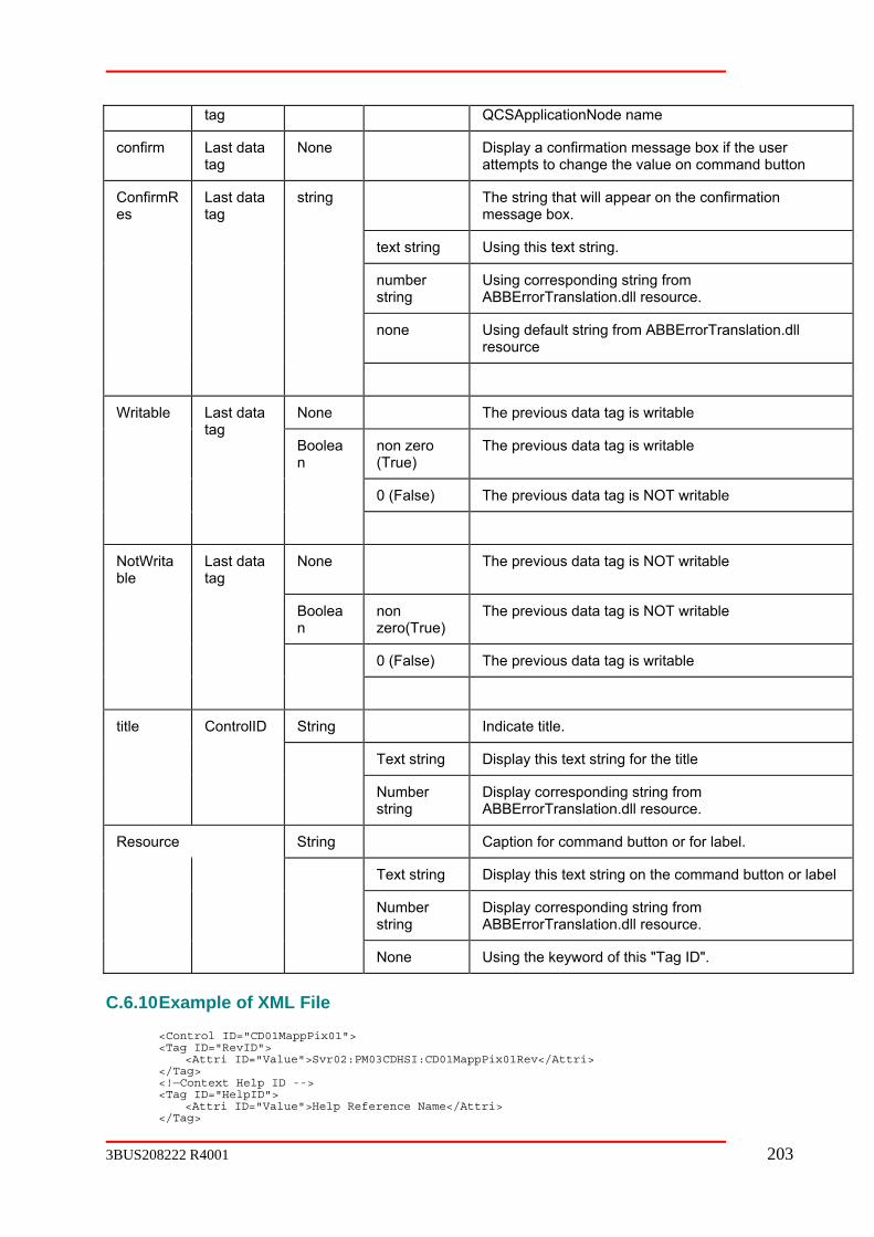
tag QCSApplicationNode name
confirm Last attempts to change the value on command button
data tag
None Display a confirmation message box if the user
The string that will appear on the confirmation message box.
text string Using this text string.
number string
Using corresponding string from ABBErrorTranslation.dll resource.
none Using default string from ABBErrorTranslation.dll resource
Confires
mR Last data string tag
None The previous data tag is writable
non zero (True)
The previous data tag is writable
0 (False) The previous data tag is NOT writable
Writable Last data
an
tag Boole
NotWritable
Last data None The previous data tag is NOT writable tag
Boolean
non zero(True)
The previous data tag is NOT writable
e) The previous data tag is writable 0 (Fals
title ControlID String Indicate title.
Text string Display this text string for the title
Number Display corresponding string from string ABBErrorTranslation.dll resource.
Resource String Caption for command button or for label.
Text string Display this text string on the command button or label
Number string
Display corresponding string from ABBErrorTranslation.dll resource.
None Using the keyword of this "Tag ID".
C.6.10 Example of XML File
<Control ID="CD01MappPix01"> <Tag ID="RevID"> <Attri ID="Value">Svr02:PM03CDHSI:CD01MappPix01Rev</Attri> </Tag> <!—Context Help ID --> <Tag ID="HelpID"> <Attri ID="Value">Help Reference Name</Attri> </Tag>
3BUS208222 R4001 203

<Tag ID="Home Reference"> <Attri ="Resource">8033</Attri>
2:PM03CD1:DPT.hrefer</Attri> /Attri>
<Tag ID="Far Reference"> <Attri <Attri <Attri ID="Writable"></Attri>
D="Home Pisser">
<Attri ID="Resource">8035</Attri> hompis</Attri>
<Attri ID="Writable"></Attri>
<Attri ID="Resource">3545</Attri> ttri ID="Value">Svr02:PM03CD1:DPT.MeshInCustUnit</Attri> ttri ID="Writable">0</Attri>
</Tag>
<Attri ID="Resource">6456</Attri>
</Tag> ame Far Offset"> ID="Resource">6458</Attri>
<Attri ID="Value">Svr02:PM03CD1:DPT.faroff</Attri>
tri> <Attri ID="Writable"></Attri>
<Attri ID="Resource">6452</Attri> <Attri ID="Value">Svr02:PM03CD1:DPT.accfar</Attri>
="Writable"></Attri>
<Tag ID="title">
C.7 ABB Enhanced Auto Grid Control
C.7.1
The Enhanced AutoGrid (EAG) is a grid style control providing the following capability:
Uses “Tag Lookup Service” (TLS) to retrieve information from the server. The EAG parses ine what to display. Specials can be done by editing the Tags XML
sions when the grid’s size changes. Rescaling can be set to Vertical and Horizontal, Vertical only, Horizontal only, or none.
ID <Attri ID="Value">Svr0 <Attri ID="Writable"><</Tag>
ID="Resource">8034</Attri> ID="Value">Svr02:PM03CD1:DPT.frefer</Attri>
</Tag><Tag I
<Attri ID="Value">Svr02:PM03CD1:DPT. <Attri ID="Writable"></Attri> </Tag> <Tag ID="Far Pisser"> <Attri ID="Resource">8036</Attri> <Attri ID="Value">Svr02:PM03CD1:DPT.farpis</Attri> <Attri ID="Writable"></Attri> </Tag> <Tag ID="Pisser Conversion"> <Attri ID="Resource">6459</Attri> <Attri ID="Value">Svr02:PM03CD1:DPT.psrcon</Attri>
</Tag> <Tag ID="Current Frame Home">
<A <A
<Tag ID="Current Frame Far"> <Attri ID="Resource">3546</Attri> <Attri ID="Value">Svr02:PM03CD1:DPT.MesfInCustUnit</Attri> <Attri ID="Writable">0</Attri> </Tag> <Tag ID="Current Frame Position"> <Attri ID="Resource">6457</Attri> <Attri ID="Value">Svr02:PM03CD1:DPT.ScanPosition</Attri> <Attri ID="Writable">0</Attri> </Tag> <Tag ID="Frame Home Offset">
<Attri ID="Value">Svr02:PM03CD1:DPT.homoff</Attri> <Attri ID="Writable"></Attri>
<Tag ID="Fr <Attri
<Attri ID="Writable"></Attri> </Tag> <Tag ID="Read Home Position"> <Attri ID="Resource">6451</Attri> <Attri ID="Value">Svr02:PM03CD1:DPT.acchom</At
</Tag> <Tag ID="Read far Position">
<Attri ID</Tag>
<Attri ID="Value">CD Mapping Test</Attri> </Tag> </Control>
Introduction
this information to determfile.
Rescales its internal dimen
204 3BUS208222 R4001

r tag names of data being displayed.
Supports display of individual array elements.
Supports display of data from different OPC Servers on different nodes within the same grid.
cking. Tags received with BAD or UNCERTAIN quality are cell basis.
ser can specify blank spacing between title and top of grid. Overlaying this area with other ake an integrated control using grid and non-grid display
k events to wrapper controls.
ng number of decimal places to display on a cell by cell basis.
Optionally allows rows to be dragged to other positions
C.7.2
Basic Structure
<Control ID="Section Name"> evID">Svr01:APP1:RevID-tag</Tag> ain"> ID="Grid Attribute">1</Attri>
</Tag> ections.
…
</Tag> </Control>
n the XML file. Setting the EAG’s QCSControlID tells the EAG which section to process. Within a Control ID section
e ain” are required, “Template” Tag ID sections are
nals the AutoGrid to previously cached information it received from the Tag
Lookup service.
The “Main” section contains the list of grid attributes that will be processed to render the grid.
d from the “Main” section. When referenced, the lines in the template are placed at the reference point in the “Main” section, and any string
the TLS to inform the control its underlying data has anged in the XML file. The tag should be an integer value that can be monitored. When the
Shows the OPC Serve
Supports colors.
Provides data quality chevisually marked on a cell by
Ucontrols allows developers to melements.
Raises various clic
Optionally allows changi
Tags XML
<Tag ID="R <Tag ID="M <Attri … …
<Tag ID="TemplateName"> Note: Templates are optional Tag ID s
…
The italics parts above have the following meanings:
Section Name is an ASCII string identifying a section withi
ar Tag ID sections. “RevID” and “Moptional if templates are desired.
The “RevID” section defines an OPC tag. Changing this tag’s value sigre-read the XML and discard any
“Template” sections may be reference
substitution specified is performed.
Svr01:APP1:RevID-Tag is used bych
3BUS208222 R4001 205

tag changes value, the EAG destroys any OPCDirect groups created and requests TLS to
th ID of “NotPub”, then the TLS will not publish the tag. Otherwise, TLS will publish the tag at startup.
e is one particular attribute of the grid. A grid display is defined by having many Grid attribute lines.
tifying this template section. More then one template section may exist. The grid attributes found in a template section can be referenced out of the
y-word section below for ore inform
Some of the following key words have row and column numbers associated with them. e used along with the following special names.
3. row = current row
4. +row = current row plus 1
ol = current column plus 1 HelpID
/Attri>
a key to search the ABBHelpFileUtility.ini file. FixedRows
<Attri ID="FixedRows">n</Attri>
FixedCols <Attri ID="FixedCols">n</Attri>
ColWidthPct <Attri ID="ColWidthPct">col,pct</Attri>
col is the column number 0-n or col or +col
ResizeM dmode</Attri>
resend the section again.
If e RevID is followed with an Attribute
Grid Attribut
TemplateName is a unique name iden
“Main” section as many times as desired. See the “Template” kem ation about templates.
Attribute Key Words
Integers may b
5. col = current column
6. +c
<Attri ID="HelpID">n<
Where HelpIDName is ASCII string passed to Help-File-Utility. The utility uses this name as
Where n is number of fixed rows in grid
Where n is number of fixed cols in grid
Where
pct is the percentage of entire grid this column uses o eHorz
<Attri ID="ResizeModeHorz">
Where mode is “Standard”, “Auto”, or “None”
206 3BUS208222 R4001

causes the cells to rescale horizontally as the grid is resized horizontally. This is the default mode,
“Auto” is same as “Standard” except limits can be set for max and min cell width
d horizontally when
ResizeModeVert ="ResizeModeVert">mode</Attri>
mode is “Standard”, “Auto”, or “None”
“Standard” causes the cells to rescale vertically as the grid is resized vertically. This is the default mode, and is used by most controls.
“Auto” is same as “Standard” except limits can be set for max and min cell height. “None” means the cells are not resized vertically when grid is resized.
“Standard”
and is used by most controls.
“None” means the cells are not resizegrid is resized.
<Attri ID
Where
3BUS208222 R4001 207
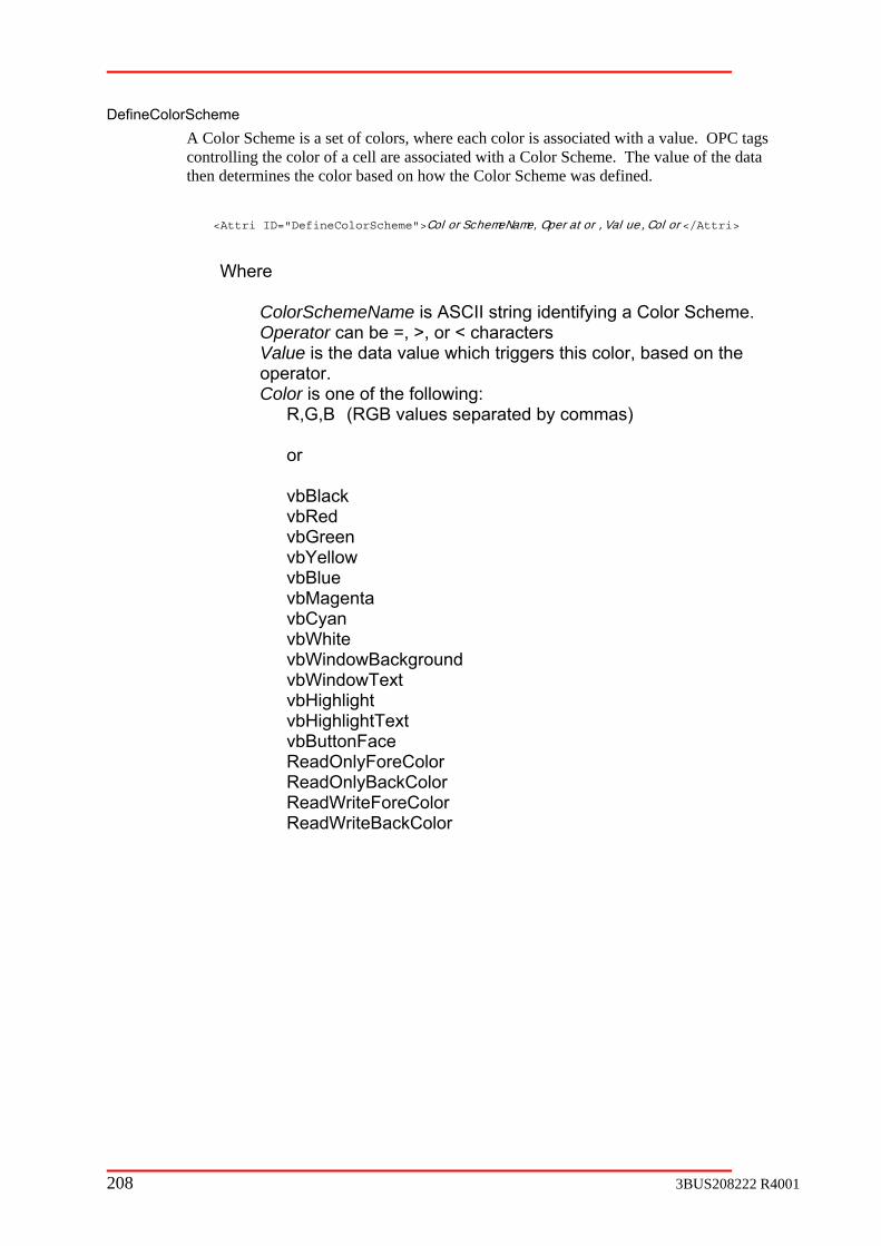
DefineCA Color Scheme is a set of colors, where each color is associated with a value. OPC tags
cell are associated with a Color Scheme. The value of the data r based on how the Color Scheme was defined.
Attri>
orSchemeName is ASCII string identifying a Color Scheme. Operator can be =, >, or < characters
Color is one of the following: R,G,B (RGB values separated by commas)
vbBlack
vbGreen vbYellow vbBlue vbMagenta vbCyan
vbWindowBackground bWindowText
vbHighlight vbHighlightText vbButtonFace
olor ReadWriteBackColor
olorScheme
controlling the color of athen determines the colo
<Attri ID="DefineColorScheme">ColorSchemeName,Operator,Value,Color</
Where
Col
Value is the data value which triggers this color, based on the operator.
or
vbRed
vbWhite
v
ReadOnlyForeColor ReadOnlyBackColor ReadWriteForeC
208 3BUS208222 R4001

CellForeThis keyword has two formats. One specifies the color using RGB numbers, and the
specifies the color by mapping an OPC tag’s value to a previously defined Color me.
Specifying RGB values: ="CellForeColor">R,G,B,row,col</Attri>
row number 0-n or “row” or “+row”
col is the column number 0-n or col or +col
Tag: <Attri ID="CellForeColor">Svr01:APP1:tag,row,col,ColorScheme</Attri>
an OPC Server tag. The Tag Lookup Service
HSIServer.xml. If the tag is an array, tag(n) can be used to reference the nth element of the array, where n is > 0.
the row number 0-n or “row” or “+row”
rSchemeName is ASCII string identifying a Color
word. CellBac
other
<Attri ID="CellBackColor">R,G,B,row,col</Attri>
ow” col is the column number 0-n or col or “+col”
Tag is an OPC Server tag. The Tag Lookup Service replaces Svr01: and APP1: with whats defined in HSIServer.xml. If the tag is an array, tag(n) can be used to reference the nth element of the array, where n is > 0.
Color
otherSche
<Attri ID
Where row is the
Specifying an OPC
Where Tag isreplaces Svr01: and APP1: with whats defined in
row is
col is the column number 0-n or “col” or “+col” ColoScheme previously defined with the DefineColorSheme key
kColor
This keyword has two formats. One specifies the color using RGB numbers, and the specifies the color by mapping an OPC tag’s value to a previously defined Color Scheme.
Specifying RGB values:
Where row is the row number 0-n or “row” or “+r
Specifying an OPC Tag:
<Attri ID="CellBackColor">Svr01:APP1:tag,row,col,ColorScheme</Attri>
Where
3BUS208222 R4001 209

row is the row number 0-n or “row” or “+row” col is the column number 0-n or “col” or “+col” ColorSchemeName is ASCII string identifying a Color Scheme previously defined with the DefineColorSheme key word.
Title
CII string used for the grid title. This argument is assumed to be an ASCII constant or a string-resource-number and string delimited with a ‘|’ character.
DeineCell
AsciiConstant cell types, tag is the ASCII constant to be
tag. The Tag Lookup Service replaces Svr01: and APP1: with what’s defined in HSIServer.xml. If the tag is an array, tag (n) can be used to reference the nth element of the array, where n is
wing are all valid examples: PM1.AC450B.SYSDATA.SystemCounter Svr01:APP1:AC450B.SYSDATA.SystemCounter
:SQCS.SP1.CLT.Current.UVIncluded.PriCustCoord.
row is the row number 0-n or “row” or “+row”
icates if operator entry should be allowed on tag. T if
stant (The tag argument is assumed to be the
character) CheckBox Button String Float Integer Date Time
<Attri ID="Title">Title</Attri>
Where Title is AS
<Attri ID="DefineCell">Svr01:APP1:tag,row,col,writable,type</Attri>
Where
Fordisplayed in cell. For all other cell types, Tag is an OPC Server
> 0. The follo
Svr01:APP1Measurement(0)
col is the column number 0-n or “col” or “+col” writable indoperator can write to tag, F if not. Type is one of the following:
AsciiConASCII constant or a string-resource-number and string delimited with a ‘|’
210 3BUS208222 R4001

MapToCellWritable AlignCell
D="AlignCell">row,col,Alignment</Attri>
r “+row”
Alignment is one of the following: Left Right Center
DefineAlarmScheme on. The
OPC tag driving the alarm indicator is setup using the DefineCellAlarm key word. If the hes any of the values in the scheme, then the alarm condition is true, and
ed. Otherwise, no alarm is displayed. <Attri ID="DefineAlarmScheme">AlarmSchemeName,Value</Attri>
Value is an alarm condition value. Boolean values are ASCII True and False
DefineCellAlarm :tag,row,col,AlarmSchemeName </Attri>
Where
Tag is an OPC Server tag. The Tag Lookup Service PP1: with what is defined in
HSIServer.xml. If the tag is an array, tag (n) can be used to reference the nth element of the array, where n is > 0.
r 0-n or “row” or “+row” col is the column number 0-n or “col” or “+col”
SchemeName is ASCII string identifying an Alarm Scheme previously defined with the DefineAlarmScheme key word
DefineWarningScheme h value represents a warning condition.
The OPC tag driving the warning indicator is setup using the DefineCellWarning key he tag’s value matches any of the values in the scheme, then the warning is true, and the yellow warning indicator is displayed. Otherwise, no warning is
<Attri I
Where
row is the row number 0-n or “row” o
col is the column number 0-n or “col” or “+col”
An Alarm Scheme is a set of values, where each value represents an alarm conditi
tag’s value matcthe red alarm indicator is display
Where
AlarmSchemeName is ASCII string identifying an Alarm Scheme.
<Attri ID="DefineCellAlarm"> Svr01:APP1
replaces Svr01: and A
row is the row numbe
Alarm
A Warning Scheme is a set of values, where eac
word. If tconditiondisplayed.
3BUS208222 R4001 211
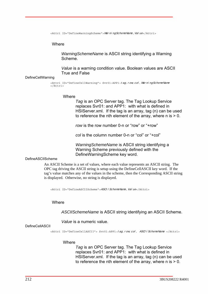
<Attri ID="DefineWarningScheme">
WarningSchemeName,Value</Attri>
is ASCII string identifying a Warning
Value is a warning condition value. Boolean values are ASCII
DefineC<Attri ID="DefineCellWarning"> Svr01:APP1:tag,row,col,WarningSchemeName
tri>
Tag is an OPC Server tag. The Tag Lookup Service replaces Svr01: and APP1: with what is defined in HSIServer.xml. If the tag is an array, tag (n) can be used
element of the array, where n is > 0. row is the row number 0-n or “row” or “+row” col is the column number 0-n or “col” or “+col” WarningSchemeName is ASCII string identifying a Warning Scheme previously defined with the
e key word. DefineASCIIScheme
SCII Scheme is a set of values, where each value represents an ASCII string. The tag driving the ASCII string is setup using the DefineCellASCII key word. If the
the values in the scheme, then the Corresponding ASCII string string is displayed.
="DefineASCIIScheme">ASCIISchemeName,Value</Attri>
Where
Value is a numeric value. DefineC
tag,row,col, ASCIISchemeName </Attri>
Where Tag is an OPC Server tag. The Tag Lookup Service
f the tag is an array, tag (n) can be used to reference the nth element of the array, where n is > 0.
Where
WarningSchemeName Scheme.
True and False ellWarning
</At
Where
to reference the nth
DefineWarningSchem
An AOPCtag’s value matches any of is displayed. Otherwise, no
<Attri ID
ASCIISchemeName is ASCII string identifying an ASCII Scheme.
ellASCII <Attri ID="DefineCellASCII"> Svr01:APP1:
replaces Svr01: and APP1: with what is defined in HSIServer.xml. I
212 3BUS208222 R4001

ber 0-n or “row” or “+row” col is the column number 0-n or “col” or “+col”
SchemeName is ASCII string identifying an ASCII Scheme previously defined with the DefineASCIIScheme key word
Templabe replaced by the lines found in the specified template
section. String substitution will be performed on keys found in the template lines so each template may be customized a little.
TemplateName, DelimitedKeys,DelimitedStrings,
ame identifies a Tag ID section containing grid attribute lines.
s is a delimited list of strings that will be replaced the DelimitedStrings argument.
DelimitedStrings is a delimited list of string that will replace the DelimitedKeys strings.
ments for frame 1 BW and frame 2 MO would be row” and “col” key-words are always
d to zero.
ol,F,Float</Attr
row is the row num
ASCII
te This grid attribute line will
reference to the <Attri ID="Template">‘Delimeter’</Attri>
Where
TemplateN
DelimitedKeywith strings found in
Delimiter is the delimiter character used in the DelimitedKeys and DelimitedStrings arguments.
Example: In this example, a grid with 1 column and 2 rows would appear. Measuredisplayed. Note, the “initialize
<Control ID="MeasDisplay">
<Tag ID="RevID">Svr01:APP1:RevIDs.MeasDisplay</Tag>
<Tag ID="Main">
<Attri ID="Template"> MeasTemplate,[SP];[SN],SP1;WT,';'</Attri>
<Attri ID="Template"> MeasTemplate,[SP];[SN],SP2;MO,';'</Attri> …
</Tag>
<Tag ID="MeasTemplate">
<Attri ID="DefineCell">Svr01:APP1:[SP].[SN].Meas,+row,ci>
</Tag>
</Control>
3BUS208222 R4001 213
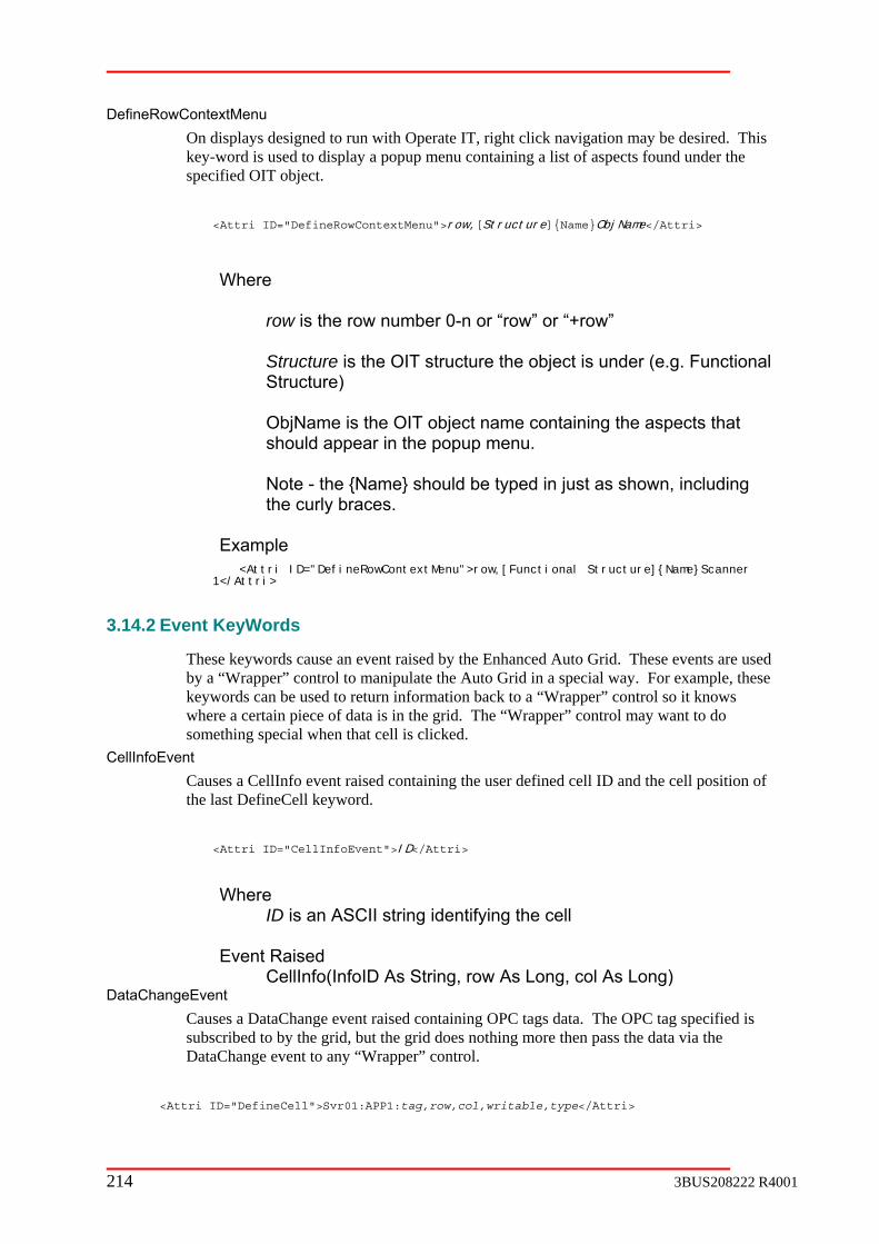
DefineR
al
ObjName is the OIT object name containing the aspects that
Note - the {Name} should be typed in just as shown, including the curly braces.
ional Structure]{Name}Scanner
3.14.2
ds cause an event raised by the Enhanced Auto Grid. These events are used r” control to manipulate the Auto Grid in a special way. For example, these
keywords can be used to return information back to a “Wrapper” control so it knows where a certain piece of data is in the grid. The “Wrapper” control may want to do something special when that cell is clicked.
CellInfoEvent Causes a CellInfo event raised containing the user defined cell ID and the cell position of the last DefineCell keyword.
<Attri ID="CellInfoEvent">ID</Attri>
Where
ID is an ASCII string identifying the cell
Causes a DataChange event raised containing OPC tags data. The OPC tag specified is ribed to by the grid, but the grid does nothing more then pass the data via the
DataChange event to any “Wrapper” control.
owContextMenu On displays designed to run with Operate IT, right click navigation may be desired. This key-word is used to display a popup menu containing a list of aspects found under the specified OIT object.
<Attri ID="DefineRowContextMenu">row,[Structure]{Name}ObjName</Attri>
Where row is the row number 0-n or “row” or “+row” Structure is the OIT structure the object is under (e.g. FunctionStructure)
should appear in the popup menu.
Example <Attri ID="DefineRowContextMenu">row,[Funct1</Attri>
Event KeyWords
These keyworby a “Wrappe
Event Raised
CellInfo(InfoID As String, row As Long, col As Long) DataChangeEvent
subsc
<Attri ID="DefineCell">Svr01:APP1:tag,row,col,writable,type</Attri>
214 3BUS208222 R4001

ngeEvent"> Svr01:APP1:tag, tagHandle</Attri>
Where tag is an OPC Server tag. The Tag Lookup Service replaces Svr01: and APP1: with what’s defined in HSIServer.xml. The following are all valid examples:
A.SystemCounter P1:AC450B.SYSDATA.SystemCounter
Event Raised DataChange(Count As Long, Hdls() As Long, Vals() As Variant, quals() As Long)
<Attri ID="DataCha
PM1.AC450B.SYSDAT Svr01:AP
3BUS208222 R4001 215

C.8
C.8.1 Introduction
The Tag Lookup Selector Control is used to select among different ControlIDs for display by or Auto Plot control. The selector is a popup menu, defined in the Tag Lookup e different menu selections are associated with different ControlIDs. When a
e selection including the ControlID.
C.8.2
">
<Attri ID="MenuTitle">Title</Attri>
>DelimitedKeys</Attri>
nuItem">LEVEL,MenuItemLabel</Attri>
<Attri ID="MenuItem">LEVEL,MenuItemLabel</Attri>
ID="Keys">DelimitedKeys </Attri>
</Tag>
the following meanings:
Name is an ASCII string identifying a section within the XML file. Setting the OR’s QCSControlID tells the SELECTOR which section to process. Within a
” are required, “Template” Tag
ABB Tag Lookup Selector Control
an Auto Gridxml file. Herselection is made, the control returns information about th
Tags XML
Basic Structure
<Control ID="SelectorName">
<Tag ID="RevID">Svr01:APP1:RevID-Tag</Tag>
<Tag ID="Main
<Attri ID="MenuItem">LEVEL,MenuItemLabel</Attri>
<Attri ID="Keys"
<Attri ID="Subs">DelimitedSubs</Attri>
<Attri ID="Template">+LEVEL,NameOfTemplate</Attri>
<Attri ID="Me
<Attri ID="ControlID">ControlID</Attri>
</Tag>
<Tag ID="NameOfTemplate">
<Attri
<Attri ID="Subs">DelimitedSubs </Attri>
</Control>
The underlined parts above have
SelectorSELECTControl ID section are Tag ID sections. “RevID” and “MainID sections are optional if templates are used.
216 3BUS208222 R4001

section defines an OPC tag. Changing this tag’s value signals the Selector to re-read the XML and discards any previously cached information it received from the Tag
in” section contains the list of selector attributes used to define the popup menu.
Svr01:APP1:RevID-Tag is used by the TLS to inform the control its underlying data has file. The tag should be an integer value that can be monitored. When the
s any OPCDirect groups created and requests TLS
If the RevID is followed with an Attribute ID of “NotPub”, then the TLS will not publish the
is defined by having
name identifying this template section. More then one template referenced out of the “Main” section as many
ction below for more information about
urce-number and string delimited with a ‘|’ character.
The “RevID”
Lookup service.
The “Ma
“Template” sections may be referenced from the “Main” section. When referenced, the lines in the template are placed at the reference point in the “Main” section.
changed in the XMLtag changes value, the SELECTOR destroyto resend the section again.
tag. Otherwise, TLS will publish the tag at startup.
Grid Attribute is one particular attribute of the grid. A grid displaymany Grid attribute lines.
TemplateName is a unique section may exist. A template section can be times as desired. See the “Template” key-word setemplates.
Attribute Key Words
MenuTitle
<Attri ID="MenuTitle">Title</Attri>
Where: Title is ASCII string used for the grid title. This argument is assumed to be an ASCII constant or a string-reso
MenuItem
<Attri ID="MenuItem">LEVEL,MenuItemLabel</Attri>
Where: LEVEL is a key word representing the menu’s current hierarchy level. A +LEVEL keyword represents the menu’s next hierarchy level.
3BUS208222 R4001 217

3-52 Heirarchy Levels Figure
If more then two levels are desired, Templating must be used.
Where: DelimitedKeys is a list of substitution keys delimited with semi colons (;). When a nd
e AutoGrid or AutoPlot through their TemplateKeys and TemplateSubs properties. When the AutoGrid and AutoPlot controls receive Attri IDs from the Tag Lookup
replace each key with the associated sub.
If Keys are defined, then there also must be the same number of Subs defined.
Subs
<Attri ID="Subs">DelimitedSubs</Attri>
bs is a list of substitution strings delimited with semi colons (;). When a final selection is made, subs from each Level are concatenated and returned. The Keys and
passed to the AutoGrid or AutoPlot through their TemplateKeys and TemplateSubs properties. When the AutoGrid and AutoPlot controls receive Attri IDs from the Tag Lookup
ere also must be the same number of Keys defined.
This attribute line will be replaced by the lines found in the specified template section.
="Template">+LEVEL,TemplateName</Attri>
containing more Selector attributes.
C.8.3 Example
hen a selection is made, a ControlID and associated substitution strings are returned by the control.
Primary
Keys
<Attri ID="Keys">DelimitedKeys</Attri>
final selection is made, keys from each Level are concatenated and returned. The Keys aSubs are passed to th
service, they will
Where: DelimitedSu
Subs are
service, they will replace each key with the associated sub.
If Subs are defined, then th
Template
<Attri ID
Where: TemplateName identifies a Tag ID section
This example creates the following popup menu. W
Frame 1
Top Color
UV Included
218 3BUS208222 R4001
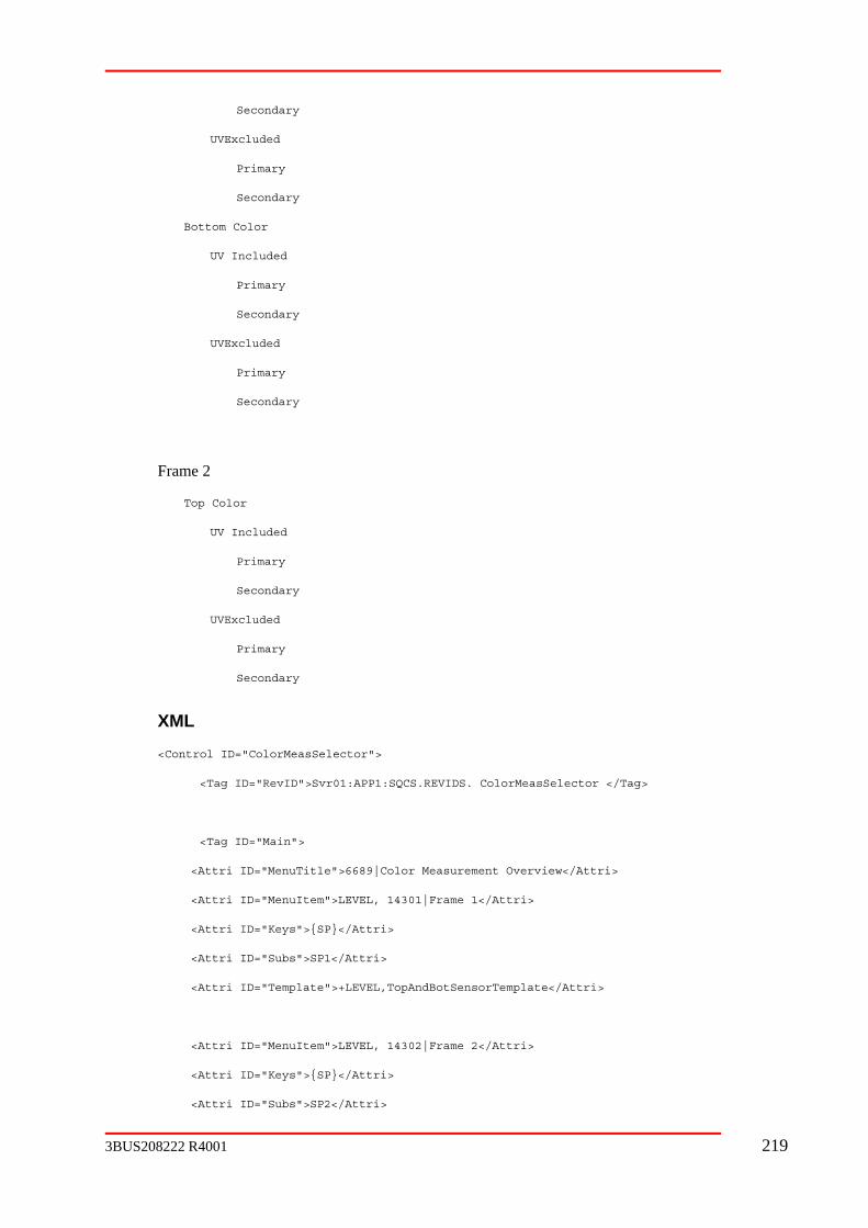
Secondary
UVExcluded
Primary
Secondary
UVExcluded
Frame 2
or
Secondary
Secondary
XML
D">Svr01:APP1:SQCS.REVIDS. ColorMeasSelector </Tag>
<Tag ID="Main">
t Overview</Attri>
tri ID="MenuItem">LEVEL, 14301|Frame 1</Attri>
<Attri ID="Subs">SP1</Attri>
emplate">+LEVEL,TopAndBotSensorTemplate</Attri>
<Attri ID="MenuItem">LEVEL, 14302|Frame 2</Attri>
eys">{SP}</Attri>
Secondary
Bottom Color
UV Included
Primary
Primary
Secondary
Top Col
UV Included
Primary
UVExcluded
Primary
<Control ID="ColorMeasSelector">
<Tag ID="RevI
<Attri ID="MenuTitle">6689|Color Measuremen
<At
<Attri ID="Keys">{SP}</Attri>
<Attri ID="T
<Attri ID="K
<Attri ID="Subs">SP2</Attri>
3BUS208222 R4001 219
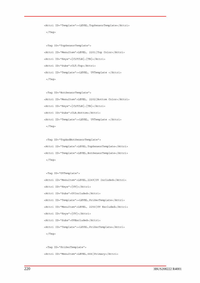
<Attri ID="Template">+LEVEL,TopSensorTemplate</Attri>
ID="TopSensorTemplate">
Color</Attri>
<Attri ID="Keys">{CLTCLB};{TB}</Attri>
ID="Subs">CLT;Top</Attri>
te </Attri>
</Tag>
<Attri ID="MenuItem">LEVEL, 2202|Bottom Color</Attri>
">{CLTCLB};{TB}</Attri>
">CLB;Bottom</Attri>
late">+LEVEL, UVTemplate </Attri>
</Tag>
<Tag ID="TopAndBotSensorTemplate">
">LEVEL,TopSensorTemplate</Attri>
</Tag>
<Attri ID="MenuItem">LEVEL,2249|UV Included</Attri>
">{UV}</Attri>
">UVIncluded</Attri>
late">+LEVEL,PriSecTemplate</Attri>
<Attri ID="MenuItem">LEVEL, 2250|UV Excluded</Attri>
<Attri ID="Subs">UVExcluded</Attri>
">+LEVEL,PriSecTemplate</Attri>
ID="PriSecTemplate">
<Attri ID="MenuItem">LEVEL,666|Primary</Attri>
</Tag>
<Tag
<Attri ID="MenuItem">LEVEL, 2201|Top
<Attri
<Attri ID="Template">+LEVEL, UVTempla
<Tag ID="BotSensorTemplate">
<Attri ID="Keys
<Attri ID="Subs
<Attri ID="Temp
<Attri ID="Template
<Attri ID="Template">LEVEL,BotSensorTemplate</Attri>
<Tag ID="UVTemplate">
<Attri ID="Keys
<Attri ID="Subs
<Attri ID="Temp
<Attri ID="Keys">{UV}</Attri>
<Attri ID="Template
</Tag>
<Tag
220 3BUS208222 R4001
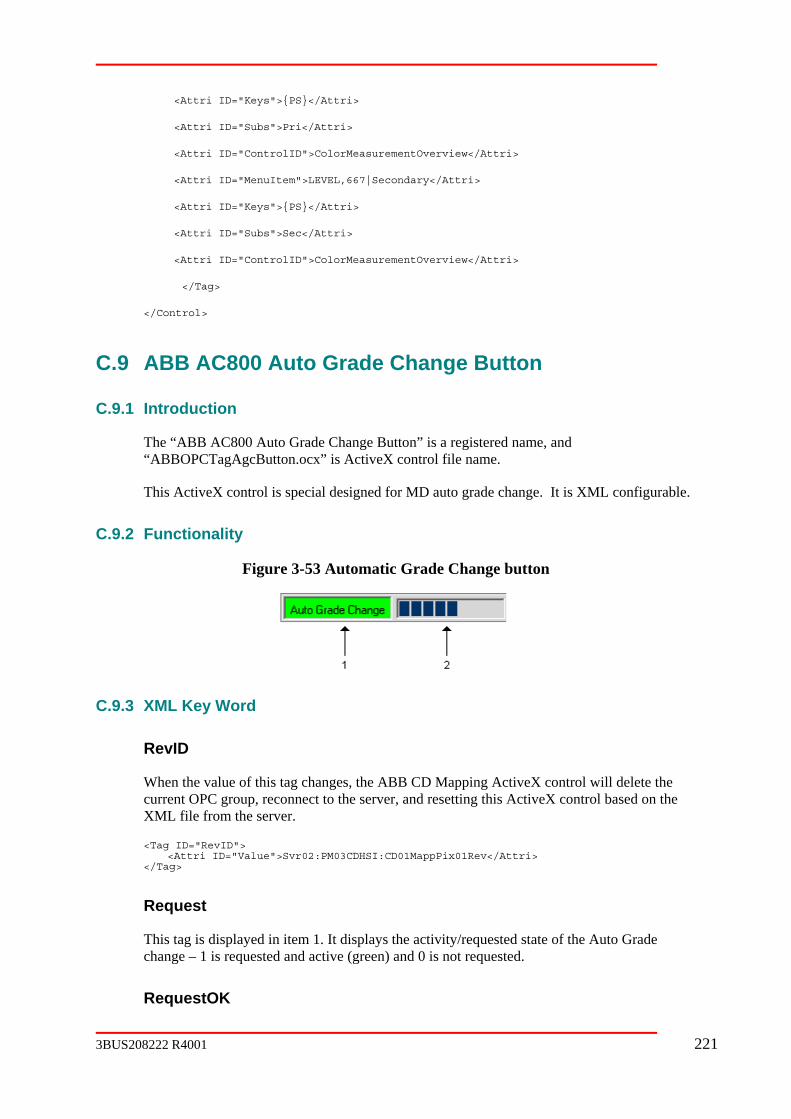
Pri</Attri>
ColorMeasurementOverview</Attri>
<Attri ID="MenuItem">LEVEL,667|Secondary</Attri>
verview</Attri>
</Control>
C.9 ABB AC800 Auto Grade Change Button
C.9.1 Introduction
Auto Grade Change Button” is a registered name, and “ABBOPCTagAgcButton.ocx” is ActiveX control file name.
This ActiveX control is special designed for MD auto grade change. It is XML configurable.
C.9.2 Functionality
Figure 3-53 Automatic Grade Change button
<Attri ID="Keys">{PS}</Attri>
<Attri ID="Subs">
<Attri ID="ControlID">
<Attri ID="Keys">{PS}</Attri>
<Attri ID="Subs">Sec</Attri>
<Attri ID="ControlID">ColorMeasurementO
</Tag>
The “ABB AC800
C.9.3 XML Key Word
RevID
When the value of this tag changes, the ABB CD Mapping ActiveX control will delete the current OPC group, reconnect to the server, and resetting this ActiveX control based on the XML file from the server.
<Tag ID="RevID"> <Attri ID="Value">Svr02:PM03CDHSI:CD01MappPix01Rev</Attri> </Tag>
t
/requested state of the Auto Grade
Reques
This tag is displayed in item 1. It displays the activitychange – 1 is requested and active (green) and 0 is not requested.
RequestOK
3BUS208222 R4001 221
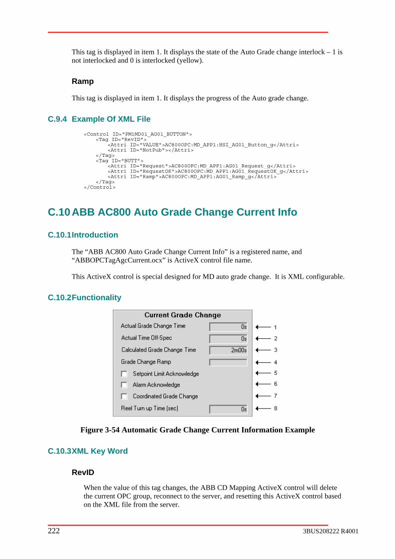
This tag is displayed in item 1. It displays the state of the Auto Grade change interlock – 1 is not interlocked and 0 is interlocked (yellow).
Ramp
This tag is displayed in item 1. It displays the progress of the Auto grade change.
C.9.4 Example Of XML File
<Control ID="PM1MD01_AG01_BUTTON"> <Tag ID="RevID"> <Attri ID="VALUE">AC800OPC:MD_APP1:HSI_AG01_Button_g</Attri> <Attri ID="NotPub"></Attri> </Tag> <Tag ID="BUTT"> <Attri ID="Request">AC800OPC:MD_APP1:AG01_Request_g</Attri> <Attri ID="RequestOK">AC800OPC:MD_APP1:AG01_RequestOK_g</Attri> <Attri ID="Ramp">AC800OPC:MD_APP1:AG01_Ramp_g</Attri> </Tag> </Control>
C.10 ABB AC800 Auto Grade Change Current Info
C.10.1 Introduction
e, and control file name.
X control is special designed for MD auto grade change. It is XML configurable.
C.10.2
The “ABB AC800 Auto Grade Change Current Info” is a registered nam“ABBOPCTagAgcCurrent.ocx” is ActiveX
This Active
Functionality
Figure 3-54 Automatic Grade Change Current Information Example
C.10.3
hanges, the ABB CD Mapping ActiveX control will delete the current OPC group, reconnect to the server, and resetting this ActiveX control based
le from the server.
XML Key Word
RevID
When the value of this tag c
on the XML fi
222 3BUS208222 R4001
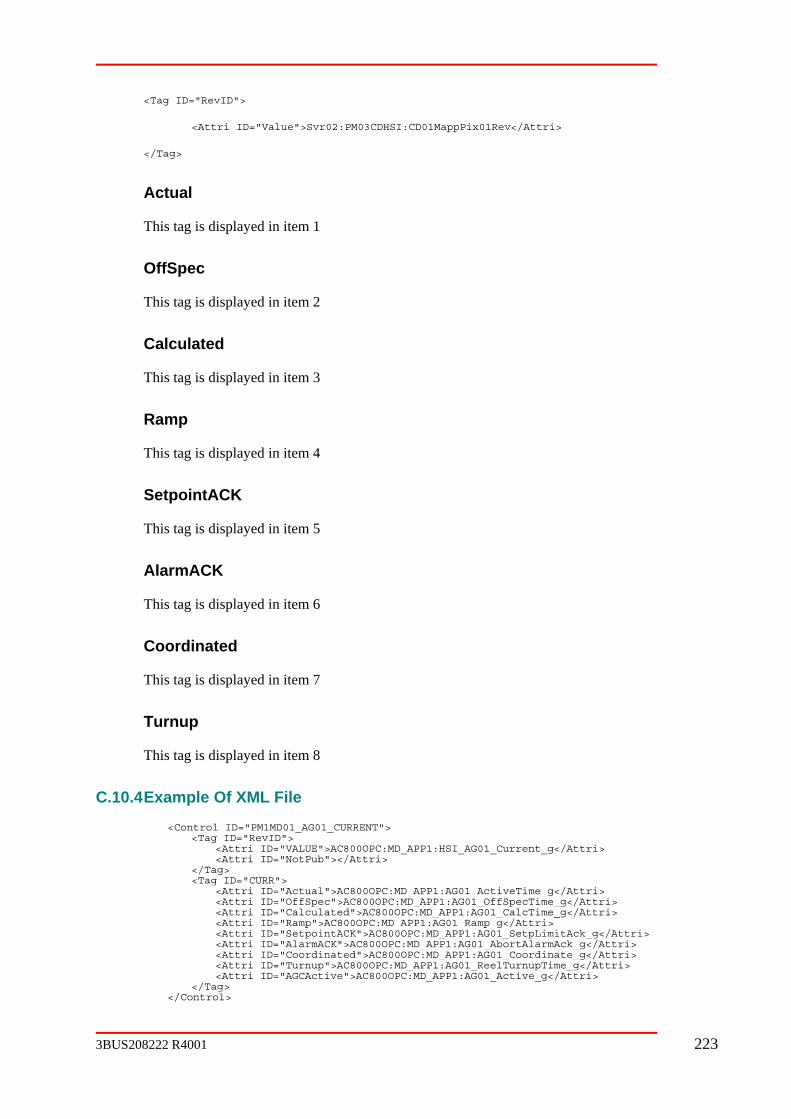
<Tag ID="RevID">
<Attri ID="Value">Svr02:PM03CDHSI:CD01MappPix01Rev</Attri>
Actual
splayed in item 1
OffSpec
isplayed in item 2
Calculated
isplayed in item 3
Ramp
played in item 4
SetpointACK
n item 5
AlarmACK
in item 6
7
ed in item 8
C.10.4
</Tag>
This tag is di
This tag is d
This tag is d
This tag is dis
This tag is displayed i
This tag is displayed
Coordinated
This tag is displayed in item
Turnup
This tag is display
Example Of XML File
<Control ID="PM1MD01_AG01_CURRENT"> <Tag ID="RevID"> <Attri ID="VALUE">AC800OPC:MD_APP1:HSI_AG01_Current_g</Attri> <Attri ID="NotPub"></Attri> </Tag> <Tag ID="CURR"> <Attri ID="Actual">AC800OPC:MD_APP1:AG01_ActiveTime_g</Attri> <Attri ID="OffSpec">AC800OPC:MD_APP1:AG01_OffSpecTime_g</Attri> <Attri ID="Calculated">AC800OPC:MD_APP1:AG01_CalcTime_g</Attri> <Attri ID="Ramp">AC800OPC:MD_APP1:AG01_Ramp_g</Attri> <Attri ID="SetpointACK">AC800OPC:MD_APP1:AG01_SetpLimitAck_g</Attri> <Attri ID="AlarmACK">AC800OPC:MD_APP1:AG01_AbortAlarmAck_g</Attri> <Attri ID="Coordinated">AC800OPC:MD_APP1:AG01_Coordinate_g</Attri> <Attri ID="Turnup">AC800OPC:MD_APP1:AG01_ReelTurnupTime_g</Attri> <Attri ID="AGCActive">AC800OPC:MD_APP1:AG01_Active_g</Attri> </Tag> </Control>
3BUS208222 R4001 223

C.11
C.11.1 Introduction
ious.ocx” is ActiveX control file name.
This ActiveX control is special designed for MD auto grade change. It is XML configurable.
C.11.2
ABB AC800 Auto Grade Change Previous
The “ABB AC800 Auto Grade Change Previous” is a registered name, and “ABBOPCTagAgcPrev
Functionality
Figure 3-55 Automatic Grade Change Previous Pop-up Example
XML Key Word
RevID
When the value of this tag changes, the ABB CD Mapping ActiveX control will delete the current OPC group, reconnect to the server, and resetting this ActiveX control based on the XML file from the server.
<Tag ID="RevID"> <Attri ID="Value">Svr02:PM03CDHSI:CD01MappPix01Rev</Attri> </Tag>
Actual
This tag is displayed in
OffSpec
This tag is displayed in item 2
Calculated
This tag is displayed in item 3
Example Of XML File
C.11.3
item 1
C.11.4
<Control ID="PM1MD01_AG01_PREVIOUS"> <Tag ID="RevID"> <Attri ID="VALUE">AC800OPC:MD_APP1:HSI_AG01_Previous_g</Attri> <Attri ID="NotPub"></Attri> </Tag> <Tag ID="PREV"> <Attri ID="Actual">AC800OPC:MD_APP1:AG01_OldActiveTime_g</Attri> <Attri ID="OffSpec">AC800OPC:MD_APP1:AG01_OldOffSpecTime_g</Attri>
224 3BUS208222 R4001

<Attri ID="Calculated">AC800OPC:MD_APP1:AG01_OldCalcTime_g</Attri> </Tag> </Control>
C.12 ABB OPC Tag AGC Level 1 Control
C.12.1 Introduction
AGC Level 1 Control” is a registered name, and “ABBOPCTagAGCL1.ocx” is ActiveX control file name.
trol is special designed for MD auto grade change level 1 control. It is XML configurable.
C.12.2 Functionalit
The “ABB OPC Tag
This ActiveX con
y
Figure 3-56 Automatic Grade Change Level 1 Control Pop-up Example
C.12.3 Word
RevID
the value of this tag changes, the ABB CD Mapping ActiveX control will delete
vID"> ID="Value">Svr02:PM03CDHSI:CD01MappPix01Rev</Attri>
</Tag>
PidAo
item 5
PidDo
item 5
GenCon
item 5
XML Key
Whenthe current OPC group, reconnect to the server, and resetting this ActiveX control based on the XML file from the server.
<Tag ID="Re <Attri
This tag is used to call up a faceplate from
This tag is used to call up a faceplate from
This tag is used to call up a faceplate from
3BUS208222 R4001 225

Measurement
This tag is displayed in item 3
play “Manual” text in item 5
This tag is used to display “External” text in item 5
tered in item 4
s if item 4 is writable
This tag is displayed in item 4
if true displays a yellow triangle in item 6.
This tag if true displays a red triangle in item 6.
d
isplay “Balance” text in item 5
splayed in item 2
sed to limit entries in item 4
Manual
This tag is used to dis
External1
OperSP
This tag is en
OperSPChange
This tag is determine
DispSP
Suspend
This tag
ExcessiveError
ExtSP
This tag is not use
Track
This tag is used d
Name
This tag is di
HighSetpoint
This tag is u
LowSetpoint
226 3BUS208222 R4001

sed to limit entries in item 4
d to request auto in item 5
uest manual in item 5
quest external in item 5
m 1
played in item 7
n item 8
eq
item 8
ritable
8 is writable
used to determine which faceplate is called up for item 5. 1 = PidAo, 2=PidDo, 3= GenCon, 4 = GenCon
C.12.4 ile
This tag is u
AutoReq
This tag is use
ManReq
This tag is used to req
Ext1Req
This tag is used to re
Required
This tag is displayed in ite
Bias
This tag is dis
New_Setpoint
This tag is displayed i
New_Setpoint_R
This tag is entered in
New_Setpoint_W
This tag determines if item
Option
This tag is
Example Of XML F
<Control ID="PM1MD01_AG01_LEVEL1GRID"> <Tag ID="RevID"> <Attri ID="VALUE">AC800OPC:MD_APP1:HSI_AG01_Level1Grid_g</Attri> <Attri ID="NotPub"></Attri> </Tag> <Tag ID="ST01"> <Attri ID="Manual">AC800OPC:MD_APP1:LC01_Level1.ST01_fb.PID_Manual</Attri> <Attri ID="External1">AC800OPC:MD_APP1:LC01_Level1.ST01_fb.PID_ExtMode</Attri> <Attri ID="OperSP">AC800OPC:MD_APP1:LC01_Level1.ST01_fb.PID_OperSP</Attri> <Attri ID="OperSPChange">AC800OPC:MD_APP1:LC01_Level1.ST01_fb.PID_SPOperChange</Attri> <Attri ID="Suspend">AC800OPC:MD_APP1:LC01_Level1.ST01_fb.PID_Suspend</Attri> <Attri ID="ExcessiveError">AC800OPC:MD_APP1:LC01_Level1.ST01_fb.ExcessiveErrorHold</Attri>
3BUS208222 R4001 227

<Attri ID="ExtSP">AC800OPC:MD_APP1:LC01_Level1.ST01_fb.PID_ExtSP</Attri> <Attri ID="Track">AC800OPC:MD_APP1:LC01_Level1.ST01_fb.PID_Track</Attri> <Attri ID="ManReq">AC800OPC:MD_APP1:LC01_Level1.ST01_fb.PID_ManReq</Attri> <Attri ID="AutoReq">AC800OPC:MD_APP1:LC01_Level1.ST01_fb.PID_AutoReq</Attri> <Attri ID="Ext1Req">AC800OPC:MD_APP1:LC01_Level1.ST01_fb.PID_ExtReq</Attri> <Attri ID="Name">AC800OPC:MD_APP1:LC01_Level1.ST01_fb.PIDDescription</Attri> <Attri ID="HighSetpoint">AC800OPC:MD_APP1:ST01_g.HighSetpoint</Attri> <Attri ID="LowSetpoint">AC800OPC:MD_APP1:ST01_g.LowSetpoint</Attri> <Attri ID="Option">AC800OPC:MD_APP1:FIC101ST_Config_g.Option</Attri> <Attri ID="Measurement">AC800OPC:MD_APP1:ST01_g.Measurement</Attri> <Attri ID="PidAo">AC800OPC:MD_APP1:LC01_Level1.ST01_fb.PidCC1.PidCC1</Attri> <Attri ID="PidDo">AC800OPC:MD_APP1:LC01_Level1.ST01_fb.PidCC1.PidCC1</Attri> <Attri ID="GenCon">AC800OPC:MD_APP1:LC01_Level1.ST01_fb.PidCC1.PidCC1</Attri> <Attri ID="Required">AC800OPC:MD_APP1:AG01_ST01_Require_g</Attri> <Attri ID="Bias">AC800OPC:MD_APP1:AG01_ST01_bias_g</Attri> <Attri ID="New_Setpoint">AC800OPC:MD_APP1:AG01_ST01_NewSetp_g</Attri> <Attri ID="New_Setpoint_Req">AC800OPC:MD_APP1:AG01_ST01_NewSetp_g</Attri> </Tag> <Tag ID="MS01"> <Attri ID="Manual">AC800OPC:MD_APP1:LC01_Level1.MS01_fb.PID_Manual</Attri> <Attri ID="External1">AC800OPC:MD_APP1:LC01_Level1.MS01_fb.PID_ExtMode</Attri> <Attri ID="OperSP">AC800OPC:MD_APP1:LC01_Level1.MS01_fb.PID_OperSP</Attri> <Attri ID="DispSP">AC800OPC:MD_APP1:LC01_Level1.MS01_fb.PID_OperSP</Attri> <Attri ID="OperSPChange">AC800OPC:MD_APP1:LC01_Level1.MS01_fb.PID_SPOperChange</Attri> <Attri ID="Suspend">AC800OPC:MD_APP1:LC01_Level1.MS01_fb.PID_Suspend</Attri> <Attri ID="ExcessiveError">AC800OPC:MD_APP1:LC01_Level1.MS01_fb.ExcessiveErrorHold</Attri> <Attri ID="ExtSP">AC800OPC:MD_APP1:LC01_Level1.MS01_fb.PID_ExtSP</Attri> <Attri ID="Track">AC800OPC:MD_APP1:LC01_Level1.MS01_fb.PID_Track</Attri> <Attr q ManReq</Attri> i ID="ManRe ">AC800OPC:MD_APP1:LC01_Level1.MS01_fb.PID_ <Attr e _AutoReq</Attri> i ID="AutoR q">AC800OPC:MD_APP1:LC01_Level1.MS01_fb.PID <Attri ID="Ext1Req">AC800OPC:MD_APP1:LC01_Level1.MS01_fb.PID_ExtReq</Attri> <Attri ID="Name">AC800OPC:MD_APP1:LC01_Level1.MS01_fb.PIDDescription</Attri> <Attri ID="HighSetpoint">AC800OPC:MD_APP1:MS01_g.HighSetpoint</Attri> <Attri ID="LowSetpoint">AC800OPC:MD_APP1:MS01_g.LowSetpoint</Attri> <Attri ID="Option">AC800OPC:MD_APP1:SIC101MS_Config_g.Option</Attri> <Attri ID="Measurement">AC800OPC:MD_APP1:MS01_g.Measurement</Attri> <Attri ID="PidAo">AC800OPC:MD_APP1:LC01_Level1.MS01_fb.PidCC1.PidCC1</Attri> <Attri ID="PidDo">AC800OPC:MD_APP1:LC01_Level1.MS01_fb.PidCC1.PidCC1</Attri> <Attri ID="GenCon">AC800OPC:MD_APP1:LC01_Level1.MS01_fb.PidCC1.PidCC1</Attri> <Attri ID="Required">AC800OPC:MD_APP1:AG01_MS01_Require_g</Attri> <Attri ID="New_Setpoint">AC800OPC:MD_APP1:GD01_SP01_Target_g</Attri> <Attri ID="New_Setpoint_Req">AC800OPC:MD_APP1:GD01_SP01_Target_g</Attri> <Attri ID="New_Setpoint_Writable">False</Attri> </Tag> </Control>
C.13
C.13.1 Introduction
The “ABB OPC Tag AGC Level2 Control” is a registered name, and e.
This ActiveX control is special designed for MD auto grade change level 2 control. It is
ABB OPC Tag AGC Level2 Control
“ABBOPCTagAGCL2.ocx” is ActiveX control file nam
XML configurable.
228 3BUS208222 R4001

C.13.2 Functionality
Figure 3-57 Automatic Grade Change Level 2 Control Pop-up Example
C.13.3 XML Key Word
When the value of this tag changes, the ABB CD Mapping ActiveX control will delete the r, and resetting this ActiveX control based on the
XML file from the server.
>
Rev</Attri>
</Tag>
This tag is displayed in item 3.
This tag is displayed in item 4. If bit 4 is true in Suspend_Bits tag, item 4 will be yellow
played in item 5.
item 5 is writable.
mit entries in item 5 and item 8
RevID
current OPC group, reconnect to the serve
<Tag ID="RevID"
<Attri ID="Value">Svr02:PM03CDHSI:CD01MappPix01
Desc
MV
background
Setpoint
This tag is dis
Setpoint_Writable
This tag determines if
Setpoint_High
This tag is used to li
3BUS208222 R4001 229
Setpoint_Low
This tag is used to limit entries in item 5 and item 8
New_Setpoint
This tag is displayed in item 8.
Setpoint_Req
This tag is entered in item 5.
tered in item 8.
mines if item 8 is writable.
play “Auto” text and color in item 6.
splay “Manual” text and color in item 6.
“E1” text and color in item 6.
d to display “E2” text and color in item 6.
play “Balance” text and color in item 6.
quest Auto in item 6.
Manual in item 6.
New_Setpoint_Req
This tag is en
New_Setpoint_Writable
This tag deter
Mode_Auto
This tag is used to dis
Mode_Man
This tag is used to di
Mode_E1
This tag is used to display
Mode_E2
This tag is use
Mode_Bal
This tag is used to dis
Mode_AutoReq
This tag is used to re
Mode_ManReq
This tag is used to request
Alarm_Suspend
230 3BUS208222 R4001

true displays a yellow triangle in item 7. If item 7 is selected with right click, a popup is shown with detailed information on the suspend reason
Suspend_Bits
This tag is used to show yellow background in item 4.
Alarm_Abort
This tag if true displays a red triangle in item 7. If item 7 is selected with right click, a popup
This tag is used to call up an aspect for item 7.
Required
1.
ed in item 2. True = green, false = yellow
StatusFill
This tag is displa 2
s displayed in item 9. If RampNumeric tag is false, the display is a pseudo bar graph, if true, then the display is numeric
g is false, the display for Ramp is a pseudo bar graph, if true, then the
t
ect faceplate for item 6.
C.13.4 ple Of XML File
This tag if
is shown with detailed information on the abort reason
Mode_fb
This tag is displayed in item
Error
This tag is display
yed in item as a filled condition.
Ramp
This tag i
RampNumeric
If RampNumeric tadisplay is numeric
Objec
This tag is used to call up an asp
Exam
<Control ID="PM1MD01_AG01_LEVEL2GRID"> <Tag ID="RevID"> <Attri ID="VALUE">AC800OPC:MD_APP1:HSI_AG01_Level2Grid_g</Attri> <Attri ID="NotPub"></Attri> </Tag> <Tag ID="DW01"> <Attri ID="Desc">AC800OPC:MD_APP1:MD01_ScanLevel.DW01_Name</Attri> <Attri ID="MV">AC800OPC:MD_APP1:DW01_OperMeas_g.Measurement</Attri> <Attri ID="Setpoint">AC800OPC:MD_APP1:DW01_Target_g</Attri>
3BUS208222 R4001 231

<Attri ID="Setpoint_Writable">AC800OPC:MD_APP1:DW01_Mode_g.OperChange</Attri> <Attri ID="Setpoint_High">AC800OPC:MD_APP1:DW01_Config_g.SetpMax</Attri> <Attri ID="Setpoint_Low">AC800OPC:MD_APP1:DW01_Config_g.SetpMin</Attri> <Attri ID="Setpoint_Req">AC800OPC:MD_APP1:DW01_Target_g</Attri> <Attri ID="New_Setpoint">AC800OPC:MD_APP1:GD01_DW01_CondWeightTarget_g</Attri> <Attri ID="New_Setpoint_Req">AC800OPC:MD_APP1:GD01_DW01_CondWeightTarget_g</Attri> <Attri ID="New_Setpoint_Writable">True</Attri> <Attri ID="Mode_Auto">AC800OPC:MD_APP1:DW01_Mode_g.Auto</Attri> <Attri ID="Mode_Man">AC800OPC:MD_APP1:DW01_Mode_g.Manual</Attri> <Attri ID="Mode_E1">AC800OPC:MD_APP1:DW01_Mode_g.External1</Attri> <Attri ID="Mode_E2">AC800OPC:MD_APP1:DW01_Mode_g.External2</Attri> <Attri ID="Mode_Bal">AC800OPC:MD_APP1:DW01_Mode_g.Bal</Attri> <Attri ID="Mode_AutoReq">AC800OPC:MD_APP1:DW01_Mode_g.Auto</Attri> <Attri ID="Alarm_Suspend">AC800OPC:MD_APP1:DW01_Mode_g.Suspend</Attri> <Attri ID="Suspend_Bits">AC800OPC:MD_APP1:DW01_Suspend_g.Bits</Attri> <Attri ID="Alarm_Abort">AC800OPC:MD_APP1:MD01_ScanLevel.DW01_AbortHold.Bits</Attri> <Attri ID="Mode_fb">AC800OPC:MD_APP1:MD01_ScanLevel.DW01_MD_Mode_fb</Attri> <Attri ID="Required">AC800OPC:MD_APP1:AG01_DW01_Require_g</Attri> <Attri ID="Error">AC800OPC:MD_APP1:AG01_DW01_ConfigError_g</Attri> <Attri ID="StatusFill">AC800OPC:MD_APP1:AG01_DW01_ConfigStatus_g</Attri> <Attri ID="Ramp">AC800OPC:MD_APP1:AG01_DW01_TargetRampPerc_g</Attri> <Attri ID="Object">AC800OPC:MD_APP1:MD01_ScanLevel.DW01_GenCon_fb</Attri> </Tag> <Tag ID="SP01"> <Attri ID="Desc">AC800OPC:MD_APP1:SP01_SpeedCtrl.SP01_Name</Attri> <Attri ID="MV">AC800OPC:MD_APP1:MS01_g.Measurement</Attri> <Attri ID="Setpoint">AC800OPC:MD_APP1:SP01_Target_g</Attri> <Attri ID="Setpoint_Writable">AC800OPC:MD_APP1:SP01_Mode_g.OperChange</Attri> <Attri ID="Setpoint_High">AC800OPC:MD_APP1:SP01_Config_g.SetpMax</Attri> <Attri ID="Setpoint_Low">AC800OPC:MD_APP1:SP01_Config_g.SetpMin</Attri> <Attri ID="Setpoint_Req">AC800OPC:MD_APP1:SP01_Target_g</Attri> <Attri ID="New_Setpoint">AC800OPC:MD_APP1:GD01_SP01_Target_g</Attri> <Attri ID="New_Setpoint_Req">AC800OPC:MD_APP1:GD01_SP01_Target_g</Attri> <Attri ID="New_Setpoint_Writable">True</Attri> <Attri ID="Mode_Auto">AC800OPC:MD_APP1:SP01_Mode_g.Auto</Attri> <Attri ID="Mode_Man">AC800OPC:MD_APP1:SP01_Mode_g.Manual</Attri> <Attri ID="Mode_E1">AC800OPC:MD_APP1:SP01_Mode_g.External1</Attri> <Attri ID="Mode_E2">AC800OPC:MD_APP1:SP01_Mode_g.External2</Attri> <Attri ID="Mode_Bal">AC800OPC:MD_APP1:SP01_Mode_g.Bal</Attri> <Attri ID="Mode_AutoReq">AC800OPC:MD_APP1:SP01_Mode_g.Auto</Attri> <Attri ID="Mode_ManReq">AC800OPC:MD_APP1:SP01_Mode_g.Manual</Attri> <Attri ID="Alarm_Suspend">AC800OPC:MD_APP1:SP01_Mode_g.Suspend</Attri> <Attri ID="Alarm_Abort">AC800OPC:MD_APP1:SP01_SpeedCtrl.SP01_AbortHold.Bits</Attri> <Attri ID="Mode_fb">AC800OPC:MD_APP1:SP01_SpeedCtrl.SP01_Mode_fb</Attri> <Attri ID="Error">AC800OPC:MD_APP1:AG01_SP01_ConfigError_g</Attri> <Attri ID="StatusFill">AC800OPC:MD_APP1:AG01_SP01_ConfigStatus_g</Attri> <Attri ID="Ramp">AC800OPC:MD_APP1:AG01_SP01_TargetRampPerc_g</Attri> <Attri ID="Object">AC800OPC:MD_APP1:SP01_SpeedCtrl.SP01_GenCon_fb</Attri> </Tag> </Control>
C.14 ABB OPC Tag Level 1 singleline
C.14.1
gistered name, and “ABBOPCTagL1C.ocx” is rol file name.
ontrol single line display. It is XML configurable.
Introduction
The “ABB OPC Tag Level 1 singleline” is a reActiveX cont
This ActiveX control is special designed for MD level 1 c
232 3BUS208222 R4001

C.14.2 Functionality
Figure 3-58 OPC Tag Level 1 SingleLine example
C.14.3
RevID
his tag changes, the ABB CD Mapping ActiveX control will delete the ctiveX control based on the
lue">Svr02:PM03CDHSI:CD01MappPix01Rev</Attri> </Tag>
sed to call up a faceplate from item 4
d to call up a faceplate from item 4
l up a faceplate from item 4
in item 2
This tag is used to display “Manual” text in item 4
This tag is used to display “External” text in item 4
This tag is entered in item 3
XML Key Word
When the value of tcurrent OPC group, reconnect to the server, and resetting this AXML file from the server.
<Tag ID="RevID"> <Attri ID="Va
PidAo
This tag is u
PidDo
This tag is use
GenCon
This tag is used to cal
Measurement
This tag is displayed
Manual
External1
OperSP
3BUS208222 R4001 233

OperSPChange
This tag is determines if item 3 is writable
This tag is displayed in item 3
Suspend
This tag if true displays a yellow triangle in item 5.
ExcessiveError
This tag if true displays a red triangle in item 5.
ExtSP
This tag is not used
Track
This tag is used to display “Balance” text in item 4
Name
This tag is displayed in item 1
HighSetpoint
This tag is used to limit entries in item 3
LowSetpoint
This tag is used to limit entries in item 3
AutoReq
This tag is used to request auto in item 4
ManReq
This tag is used to request manual in item 4
Ext1Req
This tag is used to request external in item 4
Optional1
DispSP
234 3BUS208222 R4001

This tag (if present) is displayed in item 6
Optional1_desc
This tag is not used
Optional1_type
This tag determines the type of display for item 6. 0= real, 1 = integer, 2 = checkbox, 3 =
Optional2
isplayed in item 7
c
This tag is not used
Optional2_type
This tag determines the type of display for item 7. 0= real, 1 = integer, 2 = checkbox, 3 = indicator, 4 = button.
Optional2_writable
This attribute determ
Option
s used to determine which faceplate to call up for item 4. 1 = PidAo, 2=PidDo, 3=
C.14.4
e same xml file as ABB OPC Tag Level1 Grid for a specific instance
C.15 OPC Tag Level 1 grid
C.15.1 Introduction
ame, and “ABBOPCTagL1.ocx” is ActiveX control file name.
indicator, 4 = button.
Optional1_writable
This attribute determines if item 6 is writable. (could be True or a tag)
This tag (if present) is d
Optional2_des
ines if item 6 is writable. (could be True or a tag)
This tag iGenCon, 4 = GenCon
Example Of XML File
This control uses th
ABB
The “ABB OPC Tag Level 1 grid” is a registered n
3BUS208222 R4001 235

This ActiveX control is special designed for MD level 1 grid control display. It is XML configurable.
C.15.2 Functionality
Figure 3-59 Level 1 Control Grid Example
C.15.3 XML Key Word
When the value of this tag changes, the ABB CD Mapping ActiveX control will delete the nd resetting this ActiveX control based on the
rver.
<Attri ID="Value">Svr02:PM03CDHSI:CD01MappPix01Rev</Attri> </Tag>
This tag is used to call up a faceplate from item 4
This tag is used to call up a faceplate from item 4
GenCon
This tag is used to call up a faceplate from item 4
This tag is displayed in item 2
Manual
This tag is used to display “Manual” text in item 4
External1
RevID
current OPC group, reconnect to the server, aXML file from the se
<Tag ID="RevID">
PidAo
PidDo
Measurement
236 3BUS208222 R4001

ed to display “External” text in item 4
ntered in item 3
etermines if item 3 is writable
displayed in item 3
This tag if true displays a yellow triangle in item 5.
ExcessiveError
This tag if true displays a red triangle in item 5.
yed in item 1
t
This tag is used to limit entries in item 3
AutoReq
is used to request auto in item 4
This tag is used to request manual in item 4
This tag is us
OperSP
This tag is e
OperSPChange
This tag is d
DispSP
This tag is
Suspend
ExtSP
This tag is not used
Track
This tag is used to display “Balance” text in item 4
Name
This tag is displa
HighSetpoint
This tag is used to limit entries in item 3
LowSetpoin
This tag
ManReq
3BUS208222 R4001 237

Ext1Req
This tag is used to request external in item 4
Optional1
This tag (if present) is displayed in item 6
Optional1_desc
This tag displays the text in the heading for item 6.
Optional1_type
This tag determines the type of display for item 6. 0= real, 1 = integer, 2 = checkbox, 3 =
Optional1_writable
This attribute determines if item 6 is writable. (could be True or a tag)
Optional2
This tag (if present) is displayed in item 7
type of display for item 7. 0= real, 1 = integer, 2 = checkbox, 3 =
C.15.4
indicator, 4 = button.
Optional2_desc
This tag displays the text in the heading for item 7.
Optional2_type
This tag determines theindicator, 4 = button.
Optional2_writable
This attribute determines if item 6 is writable. (could be True or a tag)
Option
This tag is used to determine which faceplate to call up for item 4. 1 = PidAo, 2=PidDo, 3= GenCon, 4 = GenCon
Example Of XML File
<Control ID="PM1MD01_LC01_LEVEL1GRID"> <Tag ID="RevID"> <Attri ID="VALUE">AC800OPC:MD_APP1:HSI_LC01_Level1Grid_g</Attri> <Attri ID="NotPub"></Attri> </Tag> <Tag ID="ST01"> <Attri ID="Manual">AC800OPC:MD_APP1:LC01_Level1.ST01_fb.PID_Manual</Attri> <Attri
238 3BUS208222 R4001

ID="External1">AC800OPC:MD_APP1:LC01_Level1.ST01_fb.PID_ExtMode</Attri> <Attri ID="OperSP">AC800OPC:MD_APP1:LC01_Level1.ST01_fb.PID_OperSP</Attri> <Attri ID="DispSP">AC800OPC:MD_APP1:LC01_Level1.ST01_fb.PID_OperSP</Attri> <Attri ID="OperSPChange">AC800OPC:MD_APP1:LC01_Level1.ST01_fb.PID_SPOperChange</Attri> <Attri ID="Suspend">AC800OPC:MD_APP1:LC01_Level1.ST01_fb.PID_Suspend</Attri> <Attri ID="ExcessiveError">AC800OPC:MD_APP1:LC01_Level1.ST01_fb.ExcessiveErrorHold</Attri> <Attri ID="ExtSP">AC800OPC:MD_APP1:LC01_Level1.ST01_fb.PID_ExtSP</Attri> <Attri ID="Track">AC800OPC:MD_APP1:LC01_Level1.ST01_fb.PID_Balance</Attri> <Attri ID="ManReq">AC800OPC:MD_APP1:LC01_Level1.ST01_fb.PID_ManReq</Attri> <Attri ID="AutoReq">AC800OPC:MD_APP1:LC01_Level1.ST01_fb.PID_AutoReq</Attri> <Attri ID="Ext1Req">AC800OPC:MD_APP1:LC01_Level1.ST01_fb.PID_ExtReq</Attri> <Attri ID="Name">AC800OPC:MD_APP1:LC01_Level1.ST01_fb.PIDDescription</Attri> <Attri ID="HighSetpoint">AC800OPC:MD_APP1:ST01_g.HighSetpoint</Attri> <Attri ID="LowSetpoint">AC800OPC:MD_APP1:ST01_g.LowSetpoint</Attri> <Attri ID="Option">AC800OPC:MD_APP1:FIC101ST_Config_g.Option</Attri> <Attri ID="Measurement">AC800OPC:MD_APP1:ST01_g.Measurement</Attri> <Attri ID="PidAo">AC800OPC:MD_APP1:LC01_Level1.ST01_fb.PidCC1.PidCC1</Attri> <Attri ID="PidDo">AC800OPC:MD_APP1:LC01_Level1.ST01_fb.PidCC1.PidCC1</Attri> <Attri ID="GenCon">AC800OPC:MD_APP1:LC01_Level1.ST01_fb.PidCC1.PidCC1</Attri> </Tag> <Tag ID="MS01"> <Attri ID="Manual">AC800OPC:MD_APP1:LC01_Level1.MS01_fb.PID_Manual</Attri> <Attri ID="External1">AC800OPC:MD_APP1:LC01_Level1.MS01_fb.PID_ExtMode</Attri> <Attri ID="OperSP">AC800OPC:MD_APP1:LC01_Level1.MS01_fb.PID_OperSP</Attri> <Attri ID="DispSP">AC800OPC:MD_APP1:LC01_Level1.MS01_fb.PID_OperSP</Attri> <Attri ID="OperSPChange">AC800OPC:MD_APP1:LC01_Level1.MS01_fb.PID_SPOperChange</Attri> <Attri ID="Suspend">AC800OPC:MD_APP1:LC01_Level1.MS01_fb.PID_Suspend</Attri> <Attri ID="ExcessiveError">AC800OPC:MD_APP1:LC01_Level1.MS01_fb.ExcessiveErrorHold</Attri> <Attri ID="ExtSP">AC800OPC:MD_APP1:LC01_Level1.MS01_fb.PID_ExtSP</Attri> <Attri ID="Track">AC800OPC:MD_APP1:LC01_Level1.MS01_fb.PID_Balance</Attri> <Attri ID="ManReq">AC800OPC:MD_APP1:LC01_Level1.MS01_fb.PID_ManReq</Attri> <Attri ID="AutoReq">AC800OPC:MD_APP1:LC01_Level1.MS01_fb.PID_AutoReq</Attri> <Attri ID="Ext1Req">AC800OPC:MD_APP1:LC01_Level1.MS01_fb.PID_ExtReq</Attri> <Attri ID="Name">AC800OPC:MD_APP1:LC01_Level1.MS01_fb.PIDDescription</Attri> <Attri ID="HighSetpoint">AC800OPC:MD_APP1:MS01_g.HighSetpoint</Attri> <Attri ID="LowSetpoint">AC800OPC:MD_APP1:MS01_g.LowSetpoint</Attri> <Attri ID="Option">AC800OPC:MD_APP1:SIC101MS_Config_g.Option</Attri> <Attri ID="Measurement">AC800OPC:MD_APP1:MS01_g.Measurement</Attri> <Attri ID="PidAo">AC800OPC:MD_APP1:LC01_Level1.MS01_fb.PidCC1.PidCC1</Attri> <Attri ID="GenCon">AC800OPC:MD_APP1:LC01_Level1.MS01_fb.PidCC1.PidCC1</Attri> </Tag> </Control>
C.16 ABB OPC Tag Level 1 Vertical
C.16.1 Introduction
The “ABB OPC Tag Level 1 Vertical” is a registered name, and “ABBOPCTagL1V.ocx” is ActiveX control file name.
This ActiveX control is special designed for MD level 1 control single vertical display. It is XML configurable.
3BUS208222 R4001 239

240 3BUS208222 R4001
C.16.2 Functionality
Figure 3-60 OPC Tag Level 1 Vertical Example
C.16.3 XML Key Word
RevID
When the value of this tag changes, the ABB CD Mapping ActiveX control will delete the current OPC group, reconnect to the server, and resetting this ActiveX control based on the XML file from the server.
<Tag ID="RevID"> <Attri ID="Value">Svr02:PM03CDHSI:CD01MappPix01Rev</Attri> </Tag>
PidAo
This tag is used to call up a faceplate from item 2
PidDo
This tag is used to call up a faceplate from item 2
GenCon
This tag is used to call up a faceplate from item 2
Measurement
This tag is displayed in item 3
Manual
This tag is used to display “Manual” text in item 2
External1
This tag is used tp display “External” text in item 2
OperSP
This tag is not used
OperSPChange

3BUS208222 R4001 241
This tag is not used
DispSP
This tag is not used
Suspend
This tag if true displays a yellow triangle in item 2.
ExcessiveError
This tag if true displays a red triangle in item 2.
ExtSP
This tag is not used
Track
This tag is used to display “Balance” text in item 2
Name
This tag is displayed in item 1
HighSetpoint
This tag is not used
LowSetpoint
This tag is not used
AutoReq
This tag is used to request auto in item 2
ManReq
This tag is used to request manual in item 2
Ext1Req
This tag is used to request external in item 2
Optional1
This tag is not used
242 3BUS208222 R4001
Optional1_desc
This tag is not used
Optional1_type
This tag is not used
Optional1_writable
This tag is not used
Optional2
This tag is not used
Optional2_desc
This tag is not used
Optional2_type
This tag is not used
Optional2_writable
This tag is not used
Option
This tag is used to determine which faceplate to call up for item 2. 1 = PidAo, 2=PidDo, 3= GenCon, 4 = GenCon
C.16.4 Example Of XML File
This control uses the same xml file as ABB OPC Tag Level1 Grid for a specific instance
C.17 ABB OPC Tag Level 2 singleline
C.17.1 Introduction
The “ABB OPC Tag Level 2 singleline” is a registered name, and “ABBOPCTagL2C.ocx” is ActiveX control file name.
This ActiveX control is special designed for MD level 2 control single line display. It is XML configurable.

3BUS208222 R4001 243
C.17.2 Functionality
Figure 3-61 OPC Tag Level 2 SingleLine Example
C.17.3 XML Key Word
RevID
When the value of this tag changes, the ABB CD Mapping ActiveX control will delete the current OPC group, reconnect to the server, and resetting this ActiveX control based on the XML file from the server.
<Tag ID="RevID"> <Attri ID="Value">Svr02:PM03CDHSI:CD01MappPix01Rev</Attri> </Tag>
Desc
This tag is displayed in item 1.
MV
This tag is displayed in item 2. If bit 4 is true in Suspend_Bits tag, item 2 will be yellow background
Setpoint
This tag is displayed in item 3.
Setpoint_Writable
This tag determines if item 3 is writable.
Setpoint_High
This tag is used to limit entries in item 3 and item 5
Setpoint_Low
This tag is used to limit entries in item 3 and item 5
New_Setpoint
This tag is displayed in item 5.
244 3BUS208222 R4001
Setpoint_Req
This tag is entered in item 3.
New_Setpoint_Req
This tag is entered in item 5.
New_Setpoint_Writable
This tag determines if item 5 is writable.
Mode_Auto
This tag is used to display “Auto” text and color in item 4.
Mode_Man
This tag is used to display “Manual” text and color in item 4.
Mode_E1
This tag is used to display “E1” text and color in item 4.
Mode_E2
This tag is used to display “E2” text and color in item 6.
Mode_Bal
This tag is used to display “Balance” text and color in item 4.
Mode_AutoReq
This tag is used to request Auto in item 4.
Mode_ManReq
This tag is used to request Manual in item 4.
Alarm_Suspend
This tag if true displays a yellow triangle in item 6. If item 6 is selected with right click, a popup is shown with detailed information on the suspend reason
Suspend_Bits
This tag is used fo show yellow background in item 2.
3BUS208222 R4001 245
Alarm_Abort
This tag if true displays a red triangle in item 6. If item 6 is selected with right click, a popup is shown with detailed information on the abort reason
Mode_fb
This tag is used to call up an aspect for item 6.
Optional1
This tag is not used
Optional1_desc
This tag is not used
Optional1_type
This tag is not used
Optional1_writable
This tag is not used
Optional2
This tag is not used
Optional2_desc
This tag is not used
Optional2_type
This tag is not used
Optional2_writable
This tag is not used
Object
This tag is used to call up an aspect faceplate for item 4.
Drystock_on
This tag (if present) displays item 4 as a button.
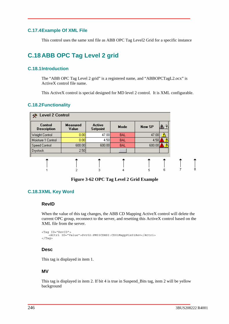
246 3BUS208222 R4001
C.17.4 Example Of XML File
This control uses the same xml file as ABB OPC Tag Level2 Grid for a specific instance
C.18 ABB OPC Tag Level 2 grid
C.18.1 Introduction
The “ABB OPC Tag Level 2 grid” is a registered name, and “ABBOPCTagL2.ocx” is ActiveX control file name.
This ActiveX control is special designed for MD level 2 control. It is XML configurable.
C.18.2 Functionality
Figure 3-62 OPC Tag Level 2 Grid Example
C.18.3 XML Key Word
RevID
When the value of this tag changes, the ABB CD Mapping ActiveX control will delete the current OPC group, reconnect to the server, and resetting this ActiveX control based on the XML file from the server.
<Tag ID="RevID"> <Attri ID="Value">Svr02:PM03CDHSI:CD01MappPix01Rev</Attri> </Tag>
Desc
This tag is displayed in item 1.
MV
This tag is displayed in item 2. If bit 4 is true in Suspend_Bits tag, item 2 will be yellow background

3BUS208222 R4001 247
Setpoint
This tag is displayed in item 3.
Setpoint_Writable
This tag determines if item 3 is writable.
Setpoint_High
This tag is used to limit entries in item 3 and item 5
Setpoint_Low
This tag is used to limit entries in item 3 and item 5
New_Setpoint
This tag is displayed in item 5.
Setpoint_Req
This tag is entered in item 3.
New_Setpoint_Req
This tag is entered in item 5.
New_Setpoint_Writable
This tag determines if item 5 is writable.
Mode_Auto
This tag is used to display “Auto” text and color in item 4.
Mode_Man
This tag is used to display “Manual” text and color in item 4.
Mode_E1
This tag is used to display “E1” text and color in item 4.
Mode_E2
This tag is used to display “E2” text and color in item 6.

248 3BUS208222 R4001
Mode_Bal
This tag is used to display “Balance” text and color in item 4.
Mode_AutoReq
This tag is used to request Auto in item 4.
Mode_ManReq
This tag is used to request Manual in item 4.
Alarm_Suspend
This tag if true displays a yellow triangle in item 6. If item 6 is selected with right click, a popup is shown with detailed information on the suspend reason
Suspend_Bits
This tag (bit 4) is used to show yellow background in item 2.
Alarm_Abort
This tag if true displays a red triangle in item 6. If item 6 is selected with right click, a popup is shown with detailed information on the abort reason
Mode_fb
This tag is used to call up an aspect for item 6.
Optional1
This tag (if present) is displayed in item 7
Optional1_desc
This tag displays the text in the heading for item 7.
Optional1_type
This tag determines the type of display for item 7. 0= real, 1 = integer, 2 = checkbox, 3 = indicator, 4 = button.
Optional1_writable
This attribute determines if item 7 is writable. (could be True or a tag)
Optional2

3BUS208222 R4001 249
This tag (if present) is displayed in item 8
Optional2_desc
This tag displays the text in the heading for item 8.
Optional2_type
This tag determines the type of display for item 8. 0= real, 1 = integer, 2 = checkbox, 3 = indicator, 4 = button.
Optional2_writable
This attribute determines if item 8 is writable. (could be True or a tag)
Object
This tag is used to call up an aspect faceplate for item 4.
Drystock_on
This tag (if present) displays item 4 as a button.
C.18.4 Example Of XML File
<Control ID="PM1MD01_MD01_LEVEL2GRID"> <Tag ID="RevID"> <Attri ID="VALUE">AC800OPC:MD_APP1:HSI_MD01_Level2Grid_g</Attri> <Attri ID="NotPub"></Attri> </Tag> <Tag ID="DW01"> <Attri ID="Desc">AC800OPC:MD_APP1:MD01_ScanLevel.DW01_Name</Attri> <Attri ID="MV">AC800OPC:MD_APP1:DW01_OperMeas_g.Measurement</Attri> <Attri ID="Setpoint">AC800OPC:MD_APP1:DW01_Target_g</Attri> <Attri ID="Setpoint_Writable">AC800OPC:MD_APP1:DW01_Mode_g.OperChange</Attri> <Attri ID="Setpoint_High">AC800OPC:MD_APP1:DW01_Config_g.SetpMax</Attri> <Attri ID="Setpoint_Low">AC800OPC:MD_APP1:DW01_Config_g.SetpMin</Attri> <Attri ID="Setpoint_Req">AC800OPC:MD_APP1:DW01_Target_g</Attri> <Attri ID="New_Setpoint">AC800OPC:MD_APP1:GD01_DW01_CondWeightTarget_g</Attri> <Attri ID="New_Setpoint_Req">AC800OPC:MD_APP1:GD01_DW01_CondWeightTarget_g</Attri> <Attri ID="New_Setpoint_Writable">False</Attri> <Attri ID="Mode_Auto">AC800OPC:MD_APP1:DW01_Mode_g.Auto</Attri> <Attri ID="Mode_Man">AC800OPC:MD_APP1:DW01_Mode_g.Manual</Attri> <Attri ID="Mode_E1">AC800OPC:MD_APP1:DW01_Mode_g.External1</Attri> <Attri ID="Mode_E2">AC800OPC:MD_APP1:DW01_Mode_g.External2</Attri> <Attri ID="Mode_Bal">AC800OPC:MD_APP1:DW01_Mode_g.Bal</Attri> <Attri ID="Mode_AutoReq">AC800OPC:MD_APP1:DW01_Mode_g.Auto</Attri> <Attri ID="Mode_ManReq">AC800OPC:MD_APP1:DW01_Mode_g.Manual</Attri> <Attri ID="Alarm_Suspend">AC800OPC:MD_APP1:DW01_Mode_g.Suspend</Attri> <Attri ID="Suspend_Bits">AC800OPC:MD_APP1:DW01_Suspend_g.Bits</Attri> <Attri ID="Alarm_Abort">AC800OPC:MD_APP1:MD01_ScanLevel.DW01_AbortHold.Bits</Attri> <Attri ID="Mode_fb">AC800OPC:MD_APP1:MD01_ScanLevel.DW01_MD_Mode_fb</Attri> <Attri ID="Object">AC800OPC:MD_APP1:MD01_ScanLevel.DW01_GenCon_fb</Attri> </Tag> <Tag ID="SP01"> <Attri ID="Desc">AC800OPC:MD_APP1:SP01_SpeedCtrl.SP01_Name</Attri> <Attri ID="MV">AC800OPC:MD_APP1:MS01_g.Measurement</Attri> <Attri ID="Setpoint">AC800OPC:MD_APP1:SP01_Target_g</Attri> <Attri ID="Setpoint_Writable">AC800OPC:MD_APP1:SP01_Mode_g.OperChange</Attri> <Attri ID="Setpoint_High">AC800OPC:MD_APP1:SP01_Config_g.SetpMax</Attri> <Attri ID="Setpoint_Low">AC800OPC:MD_APP1:SP01_Config_g.SetpMin</Attri> <Attri ID="Setpoint_Req">AC800OPC:MD_APP1:SP01_Target_g</Attri>

250 3BUS208222 R4001
<Attri ID="New_Setpoint">AC800OPC:MD_APP1:GD01_SP01_Target_g</Attri> <Attri ID="New_Setpoint_Req">AC800OPC:MD_APP1:GD01_SP01_Target_g</Attri> <Attri ID="New_Setpoint_Writable">False</Attri> <Attri ID="Mode_Auto">AC800OPC:MD_APP1:SP01_Mode_g.Auto</Attri> <Attri ID="Mode_Man">AC800OPC:MD_APP1:SP01_Mode_g.Manual</Attri> <Attri ID="Mode_E1">AC800OPC:MD_APP1:SP01_Mode_g.External1</Attri> <Attri ID="Mode_E2">AC800OPC:MD_APP1:SP01_Mode_g.External2</Attri> <Attri ID="Mode_Bal">AC800OPC:MD_APP1:SP01_Mode_g.Bal</Attri> <Attri ID="Mode_AutoReq">AC800OPC:MD_APP1:SP01_Mode_g.Auto</Attri> <Attri ID="Mode_ManReq">AC800OPC:MD_APP1:SP01_Mode_g.Manual</Attri> <Attri ID="Alarm_Suspend">AC800OPC:MD_APP1:SP01_Mode_g.Suspend</Attri> <Attri ID="Alarm_Abort">AC800OPC:MD_APP1:SP01_SpeedCtrl.SP01_AbortHold.Bits</Attri> <Attri ID="Mode_fb">AC800OPC:MD_APP1:SP01_SpeedCtrl.SP01_Mode_fb</Attri> <Attri ID="Object">AC800OPC:MD_APP1:SP01_SpeedCtrl.SP01_GenCon_fb</Attri> </Tag> <Tag ID="Drystock ON"> <Attri ID="MV">AC800OPC:MD_APP1:DS01CN01_FiltMeas_g.Value</Attri> <Attri ID="Drystock_on">AC800OPC:MD_APP1:DS01_Control_g.Value</Attri> </Tag> </Control>
C.19 ABB OPC Tag Speed Control
C.19.1 Introduction
The “ABB OPC Tag Speed Control” is a registered name, and “ABBOPCTagSpeed.ocx” is ActiveX control file name.
This ActiveX control is a grid control, it is special designed for MD speed level 1 control. It is XML configurable.
C.19.2 Functionality
Figure 3-63 OPC Tag Speed Control Example
C.19.3 XML Key Word
RevID
When the value of this tag changes, the ABB CD Mapping ActiveX control will delete the current OPC group, reconnect to the server, and resetting this ActiveX control based on the XML file from the server.
<Tag ID="RevID">
<Attri ID="Value">Svr02:PM03CDHSI:CD01MappPix01Rev</Attri>
</Tag>
PidAo

3BUS208222 R4001 251
This tag is used to call up a faceplate from item 7
PidDo
This tag is used to call up a faceplate from item 7
GenCon
This tag is used to call up a faceplate from item 7
Measurement
This tag is displayed in item 5
Manual
This tag is used to display “Manual” text in item 7
External1
This tag is used to display “External” text in item 7
OperSP
This tag is entered in item 6
OperSPChange
This tag is determines if item 6 is writable
DispSP
This tag is displayed in item 6
ExtSP
This tag is not used
Track
This tag is used display “Balance” text in item 7
Name
This tag is displayed in item 4
HighSetpoint
This tag is used to limit entries in item 6

252 3BUS208222 R4001
LowSetpoint
This tag is used to limit entries in item 6
AutoReq
This tag is used to request auto in item 7
ManReq
This tag is used to request manual in item 7
Ext1Req
This tag is used to request external in item 7
Option
This tag is used to determine which faceplate to call up for item 7. 1 = PidAo, 2=PidDo, 3= GenCon, 4 = GenCon
Required
This tag is displayed in item 1
StatusSpeed
This tag is displayed in item 2. Item 2 is unfilled yellow if not StatusSpeed and Ilock Speed. Item 2 is filled yellow if StatusSpeed and Ilock Speed. Item 2 is unfilled green if not StatusSpeed and not Ilock Speed. Item 2 is filled green if StatusSpeed and not Ilock Speed.
IlockSpeed
This tag is displayed in item 2. Item 2 is unfilled yellow if not StatusSpeed and IlockSpeed. Item 2 is filled yellow if StatusSpeed and IlockSpeed. Item 2 is unfilled green if not StatusSpeed and not IlockSpeed. Item 2 is filled green if StatusSpeed and not IlockSpeed.
StatusStock
This tag is displayed in item 3. Item 3 is unfilled yellow if not StatusStock and IlockStock. Item 3 is filled yellow if StatusStock and IlockStock. Item 3 is unfilled green if not StatusStock and not IlockStock. Item 3 is filled green if StatusStock and not IlockStock.
IlockStock
This tag is displayed in item 3. Item 3 is unfilled yellow if not StatusStock and IlockStock. Item 3 is filled yellow if StatusStock and IlockStock. Item 3 is unfilled green if not StatusStock and not IlockStock. Item 3 is filled green if StatusStock and not IlockStock.
Ramp
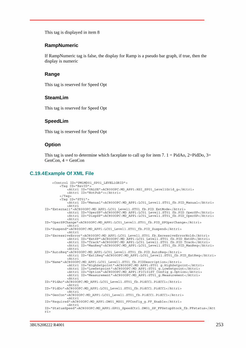
3BUS208222 R4001 253
This tag is displayed in item 8
RampNumeric
If RampNumeric tag is false, the display for Ramp is a pseudo bar graph, if true, then the display is numeric
Range
This tag is reserved for Speed Opt
SteamLim
This tag is reserved for Speed Opt
SpeedLim
This tag is reserved for Speed Opt
Option
This tag is used to determine which faceplate to call up for item 7. 1 = PidAo, 2=PidDo, 3= GenCon, 4 = GenCon
C.19.4 Example Of XML File
<Control ID="PM1MD01_SP01_LEVEL1GRID"> <Tag ID="RevID"> <Attri ID="VALUE">AC800OPC:MD_APP1:HSI_SP01_Level1Grid_g</Attri> <Attri ID="NotPub"></Attri> </Tag> <Tag ID="ST01"> <Attri ID="Manual">AC800OPC:MD_APP1:LC01_Level1.ST01_fb.PID_Manual</Attri> <Attri ID="External1">AC800OPC:MD_APP1:LC01_Level1.ST01_fb.PID_ExtMode</Attri> <Attri ID="OperSP">AC800OPC:MD_APP1:LC01_Level1.ST01_fb.PID_OperSP</Attri> <Attri ID="DispSP">AC800OPC:MD_APP1:LC01_Level1.ST01_fb.PID_OperSP</Attri> <Attri ID="OperSPChange">AC800OPC:MD_APP1:LC01_Level1.ST01_fb.PID_SPOperChange</Attri> <Attri ID="Suspend">AC800OPC:MD_APP1:LC01_Level1.ST01_fb.PID_Suspend</Attri> <Attri ID="ExcessiveError">AC800OPC:MD_APP1:LC01_Level1.ST01_fb.ExcessiveErrorHold</Attri> <Attri ID="ExtSP">AC800OPC:MD_APP1:LC01_Level1.ST01_fb.PID_ExtSP</Attri> <Attri ID="Track">AC800OPC:MD_APP1:LC01_Level1.ST01_fb.PID_Track</Attri> <Attri ID="ManReq">AC800OPC:MD_APP1:LC01_Level1.ST01_fb.PID_ManReq</Attri> <Attri ID="AutoReq">AC800OPC:MD_APP1:LC01_Level1.ST01_fb.PID_AutoReq</Attri> <Attri ID="Ext1Req">AC800OPC:MD_APP1:LC01_Level1.ST01_fb.PID_ExtReq</Attri> <Attri ID="Name">AC800OPC:MD_APP1:LC01_Level1.ST01_fb.PIDDescription</Attri> <Attri ID="HighSetpoint">AC800OPC:MD_APP1:ST01_g.HighSetpoint</Attri> <Attri ID="LowSetpoint">AC800OPC:MD_APP1:ST01_g.LowSetpoint</Attri> <Attri ID="Option">AC800OPC:MD_APP1:FIC101ST_Config_g.Option</Attri> <Attri ID="Measurement">AC800OPC:MD_APP1:ST01_g.Measurement</Attri> <Attri ID="PidAo">AC800OPC:MD_APP1:LC01_Level1.ST01_fb.PidCC1.PidCC1</Attri> <Attri ID="PidDo">AC800OPC:MD_APP1:LC01_Level1.ST01_fb.PidCC1.PidCC1</Attri> <Attri ID="GenCon">AC800OPC:MD_APP1:LC01_Level1.ST01_fb.PidCC1.PidCC1</Attri> <Attri ID="Required">AC800OPC:MD_APP1:DW01_MS01_FFConfig_g.FF_Enable</Attri> <Attri ID="StatusSpeed">AC800OPC:MD_APP1:SP01_SpeedCtrl.DW01_SP_FFSetupStock_fb.FFstatus</Attri>

254 3BUS208222 R4001
<AttriID="IlockSpeed">AC800OPC:MD_APP1:SP01_SpeedCtrl.DW01_SP_FFSetupStock_fb. FFInterlock</Attri> <AttriID="Ramp">AC800OPC:MD_APP1:SP01_SpeedCtrl.DW01_SP_FFRampStock_fb. RampPercentage</Attri> </Tag> <Tag ID="MS01"> <Attri ID="Manual">AC800OPC:MD_APP1:LC01_Level1.MS01_fb.PID_Manual</Attri> <Attri ID="External1">AC800OPC:MD_APP1:LC01_Level1.MS01_fb.PID_ExtMode</Attri> <Attri ID="OperSP">AC800OPC:MD_APP1:LC01_Level1.MS01_fb.PID_OperSP</Attri> <Attri ID="DispSP">AC800OPC:MD_APP1:LC01_Level1.MS01_fb.PID_OperSP</Attri> <Attri ID="OperSPChange">AC800OPC:MD_APP1:LC01_Level1.MS01_fb.PID_SPOperChange</Attri> <Attri ID="Suspend">AC800OPC:MD_APP1:LC01_Level1.MS01_fb.PID_Suspend</Attri> <Attri ID="ExcessiveError">AC800OPC:MD_APP1:LC01_Level1.MS01_fb.ExcessiveErrorHold</Attri> <Attri ID="ExtSP">AC800OPC:MD_APP1:LC01_Level1.MS01_fb.PID_ExtSP</Attri> <Attri ID="Track">AC800OPC:MD_APP1:LC01_Level1.MS01_fb.PID_Track</Attri> <Attri ID="ManReq">AC800OPC:MD_APP1:LC01_Level1.MS01_fb.PID_ManReq</Attri> <Attri ID="AutoReq">AC800OPC:MD_APP1:LC01_Level1.MS01_fb.PID_AutoReq</Attri> <Attri ID="Ext1Req">AC800OPC:MD_APP1:LC01_Level1.MS01_fb.PID_ExtReq</Attri> <Attri ID="Name">AC800OPC:MD_APP1:LC01_Level1.MS01_fb.PIDDescription</Attri> <Attri ID="HighSetpoint">AC800OPC:MD_APP1:MS01_g.HighSetpoint</Attri> <Attri ID="LowSetpoint">AC800OPC:MD_APP1:MS01_g.LowSetpoint</Attri> <Attri ID="Option">AC800OPC:MD_APP1:SIC101MS_Config_g.Option</Attri> <Attri ID="Measurement">AC800OPC:MD_APP1:MS01_g.Measurement</Attri> <Attri ID="PidAo">AC800OPC:MD_APP1:LC01_Level1.MS01_fb.PidCC1.PidCC1</Attri> <Attri ID="PidDo">AC800OPC:MD_APP1:LC01_Level1.MS01_fb.PidCC1.PidCC1</Attri> <Attri ID="GenCon">AC800OPC:MD_APP1:LC01_Level1.MS01_fb.PidCC1.PidCC1</Attri> <Attri ID="Ramp">AC800OPC:MD_APP1:SP01_SpeedCtrl.SP01_FFRampSpeed_fb.RampPercentage</Attri> </Tag> </Control>