industrial ethernet network infrastructure design webinar
TRANSCRIPT
Page 1
Hosted by:
Automation World
Presented by:
Mike Miclot - Belden
Brian Oulton - Belden
Industrial Ethernet Network Infrastructure
Design Webinar

Page 2
2
Your Presenters
Mike Miclot
VP Marketing
Industrial Solutions Division, Americas
Brian Oulton
Director Marketing
Global Sales & Marketing
David Greenfield
Director of Media & Events
Automation World

Page 3
Objectives • Complete the steps to design Industrial Ethernet networks
• Specify and select active and passive network components
• Identify and plan project and operational success factors
Agenda: • Logical Design
• Collect information
• Segment
• Add routers and switches
• Add network security
• Add redundancy / resiliency
• Physical Design
• Determine critical factors
• Conductors, shield, jacket, connectors
• Project and Operations Success
Focus on mainstream and easy.
Industrial Ethernet Network Design Webinar
Dock 1
D
ock 2
Control Room
Engineer
WorkStation
Line 1
Line 2
Line 3
Make 1
Make 2
Shipping
Receiving

Page 4
The Application - Manufacturing

Page 5
Do
ck
1
Do
ck
2
Control Room
Engineer
WorkStation
HM
I H
MI
Line 1
Line 2
Line 3
Make 1
Make 2
Shipping
Receiving
The Application - Manufacturing

Page 6
Panel 3
37m
20m
Panel 6
Line 3
Panel 3
37m
20m
Panel 6
Line 3
Panel 3
37m
20m
Panel 6
Line 3
Do
ck 1
D
oc
k 2
Control Room
Engineer
WorkStation
Line 1
Line 2
Line 3
Make 1
Make 2
Shipping
Receiving
Do
ck 1
D
oc
k 2
Control Room
Engineer
WorkStation
Line 1
Line 2
Line 3
Make 1
Make 2
Shipping
Receiving
P
L
C
P
L
C
P
L
C
I/
O
I/
O
D D D D D
PLC PLC PLC
Drive
Drive
Dri
ve
Dri
ve
Dri
ve
Dri
ve
Dri
ve
Panel 3
Step 1 – Collect Information D
oc
k 1
D
oc
k 2
Control Room
Engineer
WorkStation
Line 1
Line 2
Line 3
Make 1
Make 2
Shipping
Receiving
My Mfg Plant
A – Get physical drawings
C – Identify panel
locations and detail
D – General understanding of what
each part of the network needs to DO • HMI
• Control I/O
• High-speed motion
• Video / voice
• Physical security
• Business apps
B – Identify location and number
of end devices to network
E - Identify cable routing
options and distance information

Page 7
Step 2a – Segment Communications into
Groups (Subnets)
Device
Device
Device
Device
Device
Device
Device
Device
Subnet A
Layer 2
Switch
Layer 2
Switch
Layer 2
Switch
Devices on the
same subnet
easily talk
Subnets are great
for isolating: • High performance
• High bandwidth
traffic (video,
motion control)
Subnet: Break a large network into smaller
ones connected by routers or layer 3 switches
Rule of thumb 80% traffic
stays in subnet
20% traffic
travels in/out
Layer 3 Switch / Router
Device
Device
Device
Device
Device
Device
Device
Device
Layer 2
Switch
Layer 2
Switch
Layer 2
Switch
Reliability
Management
Maintenance One subnet
can be stopped
without affecting
others
Subnet B
Layer 3 Switch / Router • Connects subnets
• limits data in and out of each subnet
• provides security

Page 8
Do
ck 1
D
oc
k
2
Control Room
Engineer
WorkStation
HM
I H
MI
Line 1
Line 2
Line 3
Make 1
Make 2
Shipping
Receiving
Step 2 Example – Segment communications
into groups
A – Create physical groups based on function
and location for maintenance ease and security
Devices in a physical group
(these will become SUBNETS)
to Enterprise
What would you do? This application could be:
• 1 subnet
• 2 subnets – process and the rest
• Several subnets
For this exercise, we’ll do it as follows…

Page 9
Step 2b – Segment Communications into
Groups (VLANs – Virtual LANs)
Device
Device
Device
Device
Device
Device
Device
Device
Subnet A
Layer 2
Switch
Layer 2
Switch
Layer 2
Switch
VLAN: Create a logical groups of devices that
cannot be easily physically grouped
Rule of thumb 80% traffic
stays in VLAN
20% traffic
travels in/out
Layer 3 Switch / Router
Device
Device
Device
Device
Device
Device
Device
Device
Layer 2
Switch
Layer 2
Switch
Layer 2
Switch
VLANs are
great for
isolating • High
performance
• High bandwidth
traffic (video,
motion control)
Subnet B
Layer 3 Switch / Router are used • To configure VLANs
• Limits data in/out of VLAN
• Provides security to VLAN
OK for
devices
from
multiple
VLANs to
connect
to a
switch
Devices in the
same VLAN can
easily talk
VLAN 1
VLAN 2
Page 10
Do
ck 1
D
ock 2
Control Room
Engineer
WorkStation
HM
I H
MI
Line 1
Line 2
Line 3
Make 1
Make 2
Shipping
Receiving
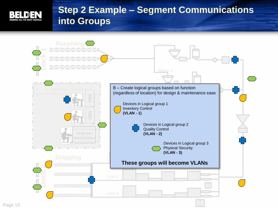
Step 2 Example – Segment Communications
into Groups
B – Create logical groups based on function
(regardless of location) for design & maintenance ease
These groups will become VLANs
Devices in Logical group 1
Inventory Control
(VLAN - 1)
Devices in Logical group 2
Quality Control
(VLAN - 2)
Devices in Logical group 3
Physical Security
(VLAN - 3)

Page 11
Step 3 – Create a Network Infrastructure
Network Infrastructure: Layout switches, routers and cabling to support
control and information throughput, easy management and expansion
Device
Device
Device
Device
Device
Device
Device
Device
Subnet A
Layer 2
Switch
Layer 2
Switch
Layer 2
Switch
Layer 3 Switch / Router
Device
Device
Device
Device
Device
Device
Device
Device
Layer 2
Switch
Layer 2
Switch
Layer 2
Switch
Subnet B
Backbone Switch
Layer 2 Switches • Connect to end devices and each other
• 100M (typical)
Layer 3 Switch / Router • Connect subnets & configure VLANs
• 1G up to backbone (typical)
to Enterprise
Backbone • Use very fast switches and fiber (10G or 1G typical)
• Carry traffic across industrial space to/from
enterprise

Page 12
Step 3 Example – Create a Network
Infrastructure (add routers and switches)
Do
ck
1
Do
ck
2
Control Room
Engineer
WorkStation
H MI
H MI
Line 1
Line 2
Line 3
Make 1
Make 2
Shipping
Receiving to Enterprise
BB – Create a
Communications
Backbone using
high-speed/high
throughput
switches -
including
connections to
Enterprise and
other facilities on
campus
L3 – Use layer 3 switches
(routers) to connect physical
groups (subnets) together.
L2 – Use layer 2 switches inside a
subnet to connect to all of that
subnet’s Ethernet devices. OK to
connect layer 2 switches together.
BB
BB
L2 L2
L2 L2
L2
L2
L2 L2
L2
L2
L2
L2
L2 L2
L2 L2 L2
L2 L2 L2 Device
Device
Device
Device
Device Device
Device Device Device
Device Device
Device Device Device
Device
Device Device
Device Device
Device Device
Device Device
Device
Device
Device
Device
Device
Device
Device
Device
Device
Device
Device
BB
L3
L3
L3

Page 13
Step 4a – Determine Other Switch
Requirements – Power over Ethernet (PoE)
Power over Ethernet (PoE) : use a single industrial Ethernet cable to provide
power and Ethernet communications to devices
Traditional Approach
Power In Power
Source Line Power
Coax Cable Signal Out
Pan/Tilt/Zoom Signals – Serial Cable
• Fewer pieces/lower cost
• Mix in existing network
infrastructure
• Low voltage with isolation
PoE Approach
Industrial Ethernet Cable
(4-pair copper)
Switch
With
PoE
Common Examples of PoE Devices

Page 14
Do
ck
1
Do
ck
2
Control Room
Engineer
WorkStation
HM
I H
MI
Line 1
Line 2
Line 3
Make 1
Make 2
Shipping
Receiving
Step 4a – Determine Other Switch Requirements
Power over Ethernet (PoE) – How to…
to Enterprise 1. Identify PoE devices you will use
(cameras, telephones, etc.)
and the switch it will connect to:
sw Switches
PoE Devices
MACH1000 MACH4000
Octopus IP67
MS 20/30
RS 20/30/40
Magnum 10KTS MACH100
Spider II
Hirschmann and Garrettcom switches with PoE support
2. Identify the power consumption (in watts) of each
device and total the power for all PoE devices wired
to one PoE switch • Most devices are “standard” PoE – up to 13 Watts
• Some devices are “PoE+” - up to 25.5 Watts.
sw
sw
sw

Page 15
What?
• IEEE 1588 (PTP – Precision Time Protocol) is designed for devices on a LAN requiring extremely precise timing accuracy (<1 microsecond). A similar older technology used is IRIG-B. These signals often are synchronized to a GPS or another master clock.
Typical Applications
• Motion control / automation
• First-fault detection
• Measurement and Testing
How?
• Determine if application needs sub-millisecond time accuracy
• Select devices for application that support IEEE-1588
• Identify/select device to provide timing reference (example: GPS)
• Ensure all switches in the path between devices needing synchronization support IEEE-1588
Step 4b – Determine Other Switch Requirements
Time Synchronization (IEEE-1588)
MACH1000
Magnum 10KT
Magnum 10KG MS 20/30
Hirschmann and GarrettCom switches with IEEE-1588 support

Page 16
Step 4c – Determine other requirements Choose IP Ratings for your switches and routers
What?
• IP ratings describe a device’s protection against solids and liquids
Why?
• Ensure industrial network infrastructure devices will survive in their environments
• Ratings can enable installation without control cabinets, reducing cost and space
IP (Ingress Protection)
Standards

Page 17
If your switch is exposed to washdown or submerged in water: IP66, 67 or 68, NEMA 4,
4X, 6, or 6P
Step 4c – Determine Other Switch Requirements
Choose IP ratings of your switches and routers – How to:
Octopus On-Machine
Ethernet Switches
IP54 and 67 IP52
Magnum 6KM
Ethernet Switches Ethernet Connectors
and Cordsets
Hirschmann and GarrettCom switches with extreme IP ratings
If your switch will be inside an enclosure:
IP20, NEMA 1 or 2

Page 18
What?
• Design appropriate security into your network infrastructure, including:
• Layer 3 switches
• Firewalls
• Features in layer 2 switches
Why?
• Physical security + network security + computer security + policies/procedures help protect your process, equipment and people
• A risk assessment helps you to match your security solution to your needs
• Security - especially if designed in - can be easy and unobtrusive
Why Not?
• Adds some cost (but prevents a lot more)
Step 5 – Add Network Security

Page 19
Step 5 – Add Network Security – How to: D
oc
k 1
D
oc
k 2
Control Room
Enginee
r
WorkSt
ation
H MI
H MI
Line 1
Line 2
Line 3
Make 1
Make 2
Shipping
Receiving to Enterprise
A - Protect each subnet:
Change the Layer 3 switches (L3)
to Eagle Router/Firewalls, but use
one per subnet.
A
A
A
Change the (BB) Backbone
switches software to Layer 3 /
router software and connect each
subnet directly to them
L3
L2 L2
L2
L2 L2
L2 L2 L2
L2 L2
L2
L2
L2
L2 L2
L2
L2
L3
L3
FW
FW
FW
B - Protect everything in this
picture from the outside with
Firewalls
FW
FW
FW
FW
FW
FW
FW
FW
BB-L3
BB-L3
BB-L3
L2
L2 L2
Page 20
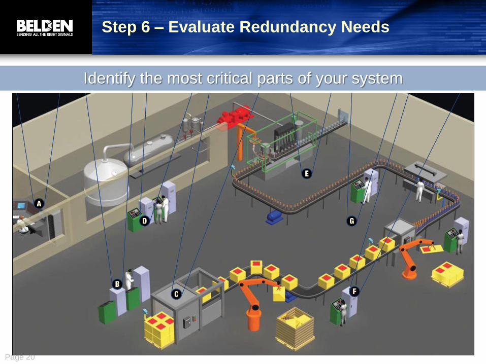
Identify the most critical parts of your system
Step 6 – Evaluate Redundancy Needs
Page 21
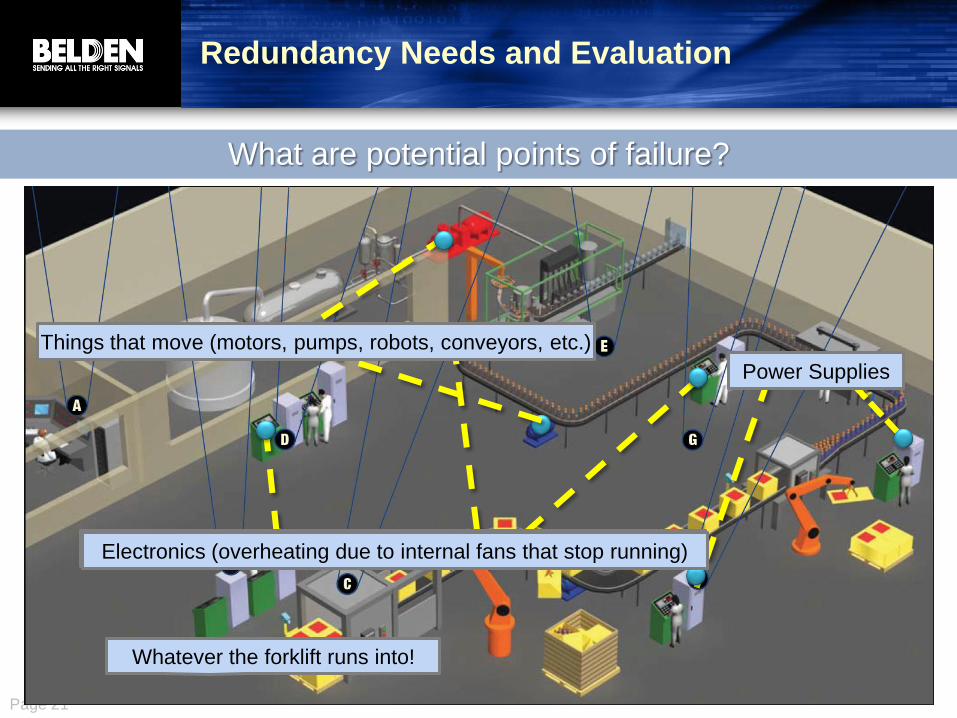
What are potential points of failure?
Redundancy Needs and Evaluation
Whatever the forklift runs into!
Things that move (motors, pumps, robots, conveyors, etc.)
Power Supplies
Electronics (overheating due to internal fans that stop running) Electronics (overheating due to internal fans that stop running)

Page 22
Step 6 – Evaluate Redundancy Needs D
oc
k 1
D
oc
k 2
Control Room
Enginee
r
WorkSt
ation
H MI
H MI
Line 1
Line 2
Line 3
Make 1
Make 2
Shipping
Receiving to Enterprise
A
A
A
C C
C C C
C C C
C C C
C C
C
C
C
C C
C
C
FW
FW
FW
FW
FW
FW
FW
FW
FW
FW
FW
BB-L3
BB-L3
BB-L3
Many expensive chemicals destroyed
if we lose communications here
Losing the backbone affects
all production!
Identify the largest needs for uptime – Rank and Assess Impact
Lose the control room and we lose our “eyes”

Page 23
Step 6 – Evaluate Redundancy Needs
Math you can do to justify an investment in redundancy
• Unplanned downtime calculator
• How long will production be impacted?
• Will product be lost?
• How much effort is needed to recover and restart your process?
• Calculate your downtime cost per minute, per hour, per day

Page 24
Step 6 – Evaluate Redundancy Needs
• ACA for any Hirschmann switch
Redundant (backup)
Configuration
• Power Supply options for any Hirschmann switch
Redundant Power
Supplies
• Ring or Tree Redundant
Ethernet Network
“Ring” MACH 100/10004000
RS 20/30/40
Tree MACH 100/1000/4000
MS 20/30
RS 20/30/40
BAT wireless
Octopus IP67
Power Supply #1
Power Supply #2
Input Power #1
Input Power #2
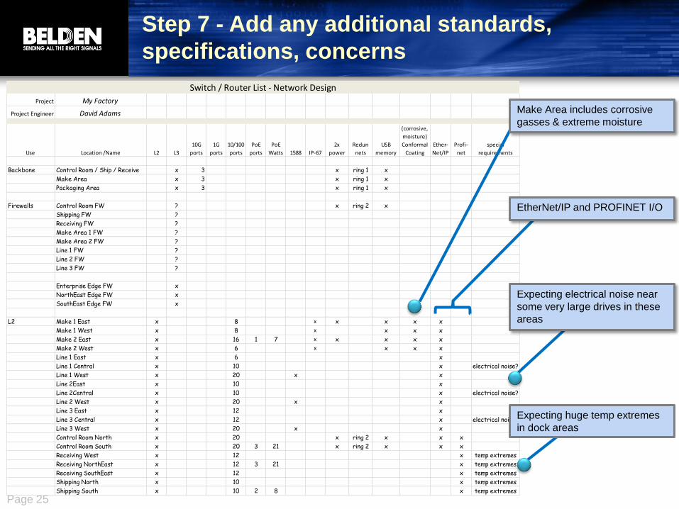
Page 25
Project My Factory
Project Engineer David Adams
Use Location /Name L2 L3
10G
ports
1G
ports
10/100
ports
PoE
ports
PoE
Watts 1588 IP-67
2x
power
Redun
nets
USB
memory
(corrosive,
moisture)
Conformal
Coating
Ether-
Net/IP
Profi-
net
special
requirements
Backbone Control Room / Ship / Receive x 3 x ring 1 x
Make Area x 3 x ring 1 x
Packaging Area x 3 x ring 1 x
Firewalls Control Room FW ? x ring 2 x
Shipping FW ?
Receiving FW ?
Make Area 1 FW ?
Make Area 2 FW ?
Line 1 FW ?
Line 2 FW ?
Line 3 FW ?
Enterprise Edge FW x
NorthEast Edge FW x
SouthEast Edge FW x
L2 Make 1 East x 8 x x x x x
Make 1 West x 8 x x x x
Make 2 East x 16 1 7 x x x x x
Make 2 West x 6 x x x x
Line 1 East x 6 x
Line 1 Central x 10 x electrical noise?
Line 1 West x 20 x x
Line 2East x 10 x
Line 2Central x 10 x electrical noise?
Line 2 West x 20 x x
Line 3 East x 12 x
Line 3 Central x 12 x electrical noise?
Line 3 West x 20 x x
Control Room North x 20 x ring 2 x x x
Control Room South x 20 3 21 x ring 2 x x x
Receiving West x 12 x temp extremes
Receiving NorthEast x 12 3 21 x temp extremes
Receiving SouthEast x 12 x temp extremes
Shipping North x 10 x temp extremes
Shipping South x 10 2 8 x temp extremes
Switch / Router List - Network Design
Step 7 - Add any additional standards,
specifications, concerns
Expecting huge temp extremes
in dock areas
Expecting electrical noise near
some very large drives in these
areas
EtherNet/IP and PROFINET I/O
Make Area includes corrosive
gasses & extreme moisture

Page 26
Why?
• Failures can occur at Ethernet switch, connectors or cabling
• Studies show a majority of network failures are cable/connector
• Which of these is most difficult to replace?
• Switches - have backup configurations
• Connectors - are usually easy to access
• Cables - are the most difficult to replace.
• So, make good Ethernet cable design decisions.
• Specify what is critical now!
Step 8 - Specify Ethernet Cables
and Connectors

Page 27
Choices, Choices, Choices…
Factors to consider
• distance
• performance
• environment
• application
• regulations & specifications
Choices to make
• Conductors
• Shield (or not)
• Jacket
• Connectors
• Pre-terminated or field-installable
We’ll make this easy…

Page 28
Specify Cable/Cordset Requirements
Specify ALL of these things that
affect you or else installers will
pick what they want.
Factors
< 80m
< 100m
< 5000m
< 100,000m
10/100M rate
1G rate
10G rate
Power over Ethernet
electrical noise (motors, drives, welders)
standard bend radius (8-10x wire diameter)
tight bend radius
high flex
outdoor
UV (sun)
washdown
moisture
Underground burial
Tray installation
Physical stress - cut-through, abrasion, crushing
hazardous environment
temp >20C or <0C
chemicals
low smoke zero halogen
regulations & standards (many)

Page 29
Step 8a - Specify Copper / Fiber
Requirements
Factors Stranded
Alloy Solid Cat 5
Cat 5e
/ Cat 6 2 pair 4 pair Shielded Unshielded
multi-
mode
single-
mode OM3/4
always
tight
buffer
always
plenum
< 80m √ √ √ √ √ √ √ √ √ √ √ √
< 100m √ √ √ √ √ √ √ √ √ √ √
< 5000m √ √ √ √
< 100,000m √ √ √
10/100M rate √ √ √ √ √ √ √ √ √ √ √ √
1G rate √ √ √ √ √ √ √ √ √ √
10G rate √ √ √ √
Power over Ethernet √ √ √ √ √ √ √
electrical noise (motors, drives, welders) √ √ √ √ √ √ √ √ √ √ √ √
standard bend radius (8-10x wire diameter) √ √ √ √ √ √ √ √ √ √ √ √ √
tight bend radius √
high flex √
Copper Fiber
Industrial Copper, ALWAYS spec:
• Bonded Pair
• CAT5e or higher
Industrial Fiber, ALWAYS spec:
• Tight buffer
• Plenum
• OM3/4
Things shaded in orange
drive each decision
Nonbonded-
Pair
Bonded-
Pair

Page 30
Step 7b - Specify Jacket Requirements
Factors UV Armor
PUR
jacket
Expose
Run
FEP
insulation
& jacket
TPE
insulation
& jacket
PE
jacket
CPE
jacket
outdoor √
UV (sun) √
washdown √
moisture
Underground burial √
Tray installation √
Physical stress - cut-through, abrasion, crushing √ √
hazardous environment √
temp >20C or <0C √ √
chemicals √
low smoke zero halogen
regulations & standards (many)
Jacket

Page 31
Step 7c - Specify Connector & Buy vs. Build
Requirements
Factors RJ-45
RJ-45 with
seal
overmold M12
Field-
installable
connectors
premade
cordset
outdoor √ √
washdown √ √
moisture √ √
chemicals √ √
time √
material cost √
precision length √
Connector / Cordset

Page 32
What considerations?
Do
ck 1
D
oc
k 2
Control Room
Engineer
WorkStation
HM
I H
MI
Line 1
Line 2
Line 3
Make 1
Make 2
Shipping
Receiving
Chemical Area
Very large motors/drives here
Inside this Cabinet
On this Machine (no control cabinet)

Page 33
Step 8 – Keys to Project and Operations
Success
Manage Manage my entire project
Design Review my design & highlight areas of risk
Assist with my design in a few key areas
Assess my situation & create my design
Install Preconfigure switches / routers
Provide industrial installation guidelines
Create custom installation instructions & drawings
Peform the installation
Peform security vulnerability testing
Peform network validation
Startup Perform startup
Provide troubleshooting
Operate Dedicated onsite engineering service
Maintain Stock spares
Stock preconfigured spares
Firmware
Switch warranty
Advanced replacement for faulty devices
Remote troubleshooting
Dedicated technical support contact
On-site troubleshooting
Troubleshooting procedures
Troubleshooting tools
Training for maintenance team
Upgrade Assess planned network changes & highlight areas of risk
Onsite visit if needed
Industrial Networking Project Checklist

Page 34
Webinar Summary
Objectives • Complete the steps to design Industrial Ethernet networks
• Specify and select active and passive network components
• Identify and plan project and operational success factors
Agenda: • Logical Design
• Collect information
• Segment
• Add routers and switches
• Add network security
• Add redundancy / resiliency
• Physical Design
• Determine critical factors
• Conductors, shield, jacket,
• Project and Operations Success
For copies of this webinar, worksheets & charts or to attend a local workshop:
http://bit.ly/ieiwebinar D
ock 1
D
ock 2
Control Room
Engineer
WorkStation
Line 1
Line 2
Line 3
Make 1
Make 2
Shipping
Receiving

Page 35
Thank you!
Merci beaucoup!
Obrigado !
Muchas gracias!
Toa chie!
Domo arigato!
Danke schön!
Grazie mille!
For copies of this webinar, worksheets & charts or to attend a local workshop:
http://bit.ly/ieiwebinar