industrial engineering in apparel production
TRANSCRIPT

Industrial engineering in apparel production
FM.indd 1 9/15/2011 12:28:41 PM

FM.indd 2 9/15/2011 12:28:41 PM

Industrial engineering in
apparel production
V Ramesh Babu
WOODHEAD PUBLISHING INDIA PVT LTDNew Delhi ● Cambridge ● Oxford ● Philadelphia
FM.indd 3 9/15/2011 12:28:41 PM
Published by Woodhead Publishing India Pvt. Ltd.Woodhead Publishing India Pvt. Ltd., G-2, Vardaan House, 7/28, Ansari Road Daryaganj, New Delhi – 110002, Indiawww.woodheadpublishingindia.com
Woodhead Publishing Limited, 80 High Street Sawston Cambridge CB22 3HJ UKwww.woodheadpublishing.com
Woodhead Publishing USA 1518 Walnut Street, Suite 1100 Philadelphia PA 19102-3406 USA
First published 2012, Woodhead Publishing India Pvt. Ltd.© Woodhead Publishing India Pvt. Ltd., 2012
This book contains information obtained from authentic and highly regardedsources. Reprinted material is quoted with permission. Reasonable efforts havebeen made to publish reliable data and information, but the authors and thepublishers cannot assume responsibility for the validity of all materials. Neitherthe authors nor the publishers, nor anyone else associated with this publication,shall be liable for any loss, damage or liability directly or indirectly caused oralleged to be caused by this book.
Neither this book nor any part may be reproduced or transmitted in anyform or by any means, electronic or mechanical, including photocopying,microfilming and recording, or by any information storage or retrieval system,without permission in writing from Woodhead Publishing India Pvt. Ltd.
The consent of Woodhead Publishing India Pvt. Ltd. does not extend tocopying for general distribution, for promotion, for creating new works, or forresale. Specific permission must be obtained in writing from WoodheadPublishing India Pvt. Ltd. for such copying.
Trademark notice: Product or corporate names may be trademarks or registeredtrademarks, and are used only for identification and explanation, without intentto infringe.
Woodhead Publishing India Pvt. Ltd. ISBN 13: 978-93-80308-17-3Woodhead Publishing India Pvt. Ltd. EAN: 9789380308173
Woodhead Publishing Ltd. ISBN 13: 978-0-85709-107-9
Typeset by 3rdEyeQ, New DelhiPrinted and bound by Replika Press Pvt. Ltd., New Delhi
FM.indd 4 9/15/2011 12:28:41 PM

Contents
Preface ixAcknowledgements xi1 Concepts of production and productivity 11.1 Introduction 11.2 Production 21.3 Productivity 51.4 Standard of living 81.5 Productivity measures 111.6 References 132 Role of apparel engineering 152.1 Introduction 152.2 Apparel engineering 162.3 Methodology 172.4 Benefits of engineering 182.5 Tools and techniques for apparel engineering 182.6 Role of industrial engineer 212.7 Pre-production activities of a supervisor 242.8 References 283 Method analysis 293.1 Definition 293.2 Recording the method 313.3 Operation process chart 333.4 Flow process chart 353.5 Flow diagram 373.6 String diagram 383.7 Travel chart (From – To chart) 403.8 Multiple activity chart (or) man–machine chart 44
FM.indd 5 9/15/2011 12:28:41 PM
vi Contents
3.9 References 454 Motion economy 474.1 Principles of motion economy 474.2 Two-handed process chart 504.3 Micro motion study 524.4 Study of method recorded 554.5 Methods improvement 604.6 References 625 Apparel production systems and factory layout 635.1 Introduction 635.2 Garment production systems 635.3 Group system 645.4 Progressive bundle synchro straight line system – batch system 665.5 Unit production system (UPS) 695.6 Quick response sewing system 715.7 Layout objectives 725.8 Designing the layout 745.9 References 776 Work measurement 796.1 Definitionofworkmeasurement 796.2 Techniques of work measurement 806.3 Time study 876.4 Selecting the job 916.5 Standard allowed minute (SAM) 966.6 Rating factor 1006.7 Allowances 1046.8 Other methods to set time standards 1086.9 References 1127 Application of IE techniques in garment industry 1137.1 Capacity study 1137.3 Operator performance 1157.4 Follow-ups 1177.5 Work in process (WIP) 120
FM.indd 6 9/29/2011 10:22:54 AM
Contents vii
7.6 Operation bulletin 1227.7 References 1278 Line balancing 1298.1 Balancing 1298.2 Steps to balance the line 1318.3 Initial balance 1348.4 Balance control (Operating a line) 1408.5 Efficiency 1428.6 Cycle checks 1438.7 Balancing tools 1458.8 References 1519 Scientific method of training 1539.1 SMT(Scientificmethodoftraining) 1539.2 Methodology behind SMT 1559.3 Selection test 1599.4 Basic exercise 1619.5 Paper exercise 1629.6 Fabric exercise 1639.7 References 16810 Industrial engineering in apparel quality control 16910.1 Introduction 16910.2 Quality is a multi-dimensional aspect 17110.3 How to control quality? 17210.4 How to achieve good quality? 17410.5 Qualityspecificationssheet 17510.6 Quality training 17610.7 References 179Index 181
FM.indd 7 9/29/2011 10:22:54 AM
Woodhead Publishing India Series in Textiles
Fundamentals and Advances in Knitting Technology • Sadhan Chandra RayTraining and Development of Technical Staff in the Textile Industry • B. PurushothamaManagement of Technology Systems in Garment Industry • Gordana Colovic A Practical Guide to Quality Management in Spinning • B. PurushothamaModern Approach to Maintenance in Spinning • Neeraj Niijjaawan and Rashmi NiijjaawanPerformance of Home Textiles• Subrata DasFundamentals and Practices in Colouration of Textiles • J. N. ChakrabortyScience in Clothing Comfort • Apurba Das and R. AlagirusamyEffective Implementation of Quality Management Systems • B. PurushothamaHandbook of Worsted Wool and Blended Suiting Process • R. S. TomarQuality Characterisation of Apparel • Subrata DasHumidification and Ventilation Management in Textile Industry • B. Purushothama Fundamentals of Designing for Textiles and Other End Uses • J. W. ParchureHigh Speed Spinning of Polyester and Its Blends with Viscose • S. Y. Nanal
FM.indd 8 9/15/2011 12:28:41 PM

Preface
The garment manufacturing and exporting industry is facing heavy challenges due to various factors including global competition, production costs increase, less productivity/efficiency, labor attrition, etc. In the present scenario we need to give a thought to the emerging situation and go deep into analysis of the situation in a realistic manner. The basic fact that our country has immense strength in human resources itself is the motivating aspect to feel for such an analysis. Our analysis arrives at a view that we need better focus and concentration in identifying the real issues, taking corrective actions suiting to the specific industrial centre or unit, empowering the workers, supervisors, executives and managers by enhancing their knowledge and ability, analyzing orders effectively and decide whether it is viable for the factory, etc. There is a lot of internal correction and openness to knowledge/technology approach that needs to be built into the minds of the facility owners and managers and so also down the line. The facilities have to upgrade as system run, rather than people run. The industrial engineering concept needs to be imparted to the facilities to increase productivity.
This book is wished-for for a broad range of readers, including students, researchers, industrialists and academicians, as well as professionals in the clothing and textile industry. For easy understanding, the text is supplemented by illustrations and photographs wherever possible. Although it is fundamentally a research monograph, it includes considerable industrial standards, techniques and practices. It is, therefore, not only useful for the academia, but also provides a handy reference for professionals in the industry.
The book is divided into 10 chapters, each with specific topic. Chapter 1 deals with the concepts of production and productivity. Chapter 2 confers the role of apparel engineering. Chapter 3 converses the techniques and the standards of method analysis and recoding techniques. Chapter 4 deals with the principle of motion economy and describes the techniques such as two-handed process chart and simo chart. Chapter 5 reviews the various apparel production systems and factory layouts. Chapter 6 presents the work measurement techniques such as work sampling, stop watch procedure and time study in detail. Chapter 7 explains the application of industrial engineering techniques in apparel industry with realistic examples. Chapter 8 deals with the line
FM.indd 9 9/15/2011 12:28:41 PM

x Preface
balancing techniques adopted in the garment industry. Chapter 9 describes the scientific approach of various training techniques imparted to the tailors. Chapter 10 reviews the industrial engineering in quality control.
FM.indd 10 9/15/2011 12:28:41 PM

Acknowledgements
I would like to express my sincere gratitude to all individuals and organizations who have directly or indirectly contributed toward the publication of this book. In particular, I would like to acknowledge:
M. A. Sathar, Research and Development Manager, Bombay Rayons, for his guidance and support for Chapter 9.
Prakash Vasudevan, CEO, PZM Solutions, for his direction and motivation toward the preparation of this book.
Raja, Senior Lecturer, Department of Fashion Technology, Sona College of Technology, for his contribution in formatting the manuscript, preparation of figures and pictures.
Sona College of Technology for providing excellent facilities and environment to complete this book.
V. Ramesh Babu
FM.indd 11 9/15/2011 12:28:41 PM
1Concepts of production and productivity
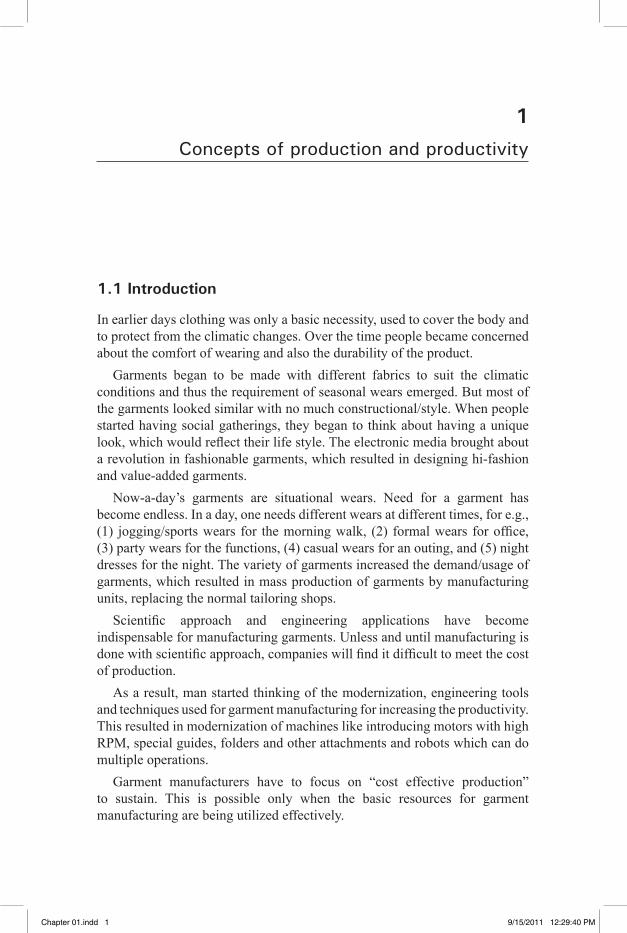
1.1 Introduction
In earlier days clothing was only a basic necessity, used to cover the body and to protect from the climatic changes. Over the time people became concerned about the comfort of wearing and also the durability of the product.
Garments began to be made with different fabrics to suit the climatic conditions and thus the requirement of seasonal wears emerged. But most of the garments looked similar with no much constructional/style. When people started having social gatherings, they began to think about having a unique look, which would reflect their life style. The electronic media brought about a revolution in fashionable garments, which resulted in designing hi-fashion and value-added garments.
Now-a-day’s garments are situational wears. Need for a garment has become endless. In a day, one needs different wears at different times, for e.g., (1) jogging/sports wears for the morning walk, (2) formal wears for office, (3) party wears for the functions, (4) casual wears for an outing, and (5) night dresses for the night. The variety of garments increased the demand/usage of garments, which resulted in mass production of garments by manufacturing units, replacing the normal tailoring shops.
Scientific approach and engineering applications have become indispensable for manufacturing garments. Unless and until manufacturing is done with scientific approach, companies will find it difficult to meet the cost of production.
As a result, man started thinking of the modernization, engineering tools and techniques used for garment manufacturing for increasing the productivity. This resulted in modernization of machines like introducing motors with high RPM, special guides, folders and other attachments and robots which can do multiple operations.
Garment manufacturers have to focus on “cost effective production” to sustain. This is possible only when the basic resources for garment manufacturing are being utilized effectively.
Chapter 01.indd 1 9/15/2011 12:29:40 PM
�� �� �� �� ��
2 Industrial engineering in apparel production
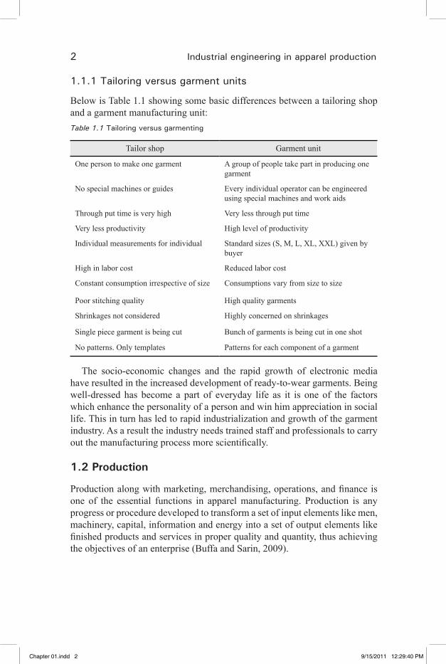
1.1.1 Tailoring versus garment units
Below is Table 1.1 showing some basic differences between a tailoring shop and a garment manufacturing unit:Table 1.1 Tailoring versus garmenting
Tailor shop Garment unit
One person to make one garment A group of people take part in producing one garment
No special machines or guides Every individual operator can be engineered using special machines and work aids
Through put time is very high Very less through put time
Very less productivity High level of productivity
Individual measurements for individual Standard sizes (S, M, L, XL, XXL) given by buyer
High in labor cost Reduced labor cost
Constant consumption irrespective of size Consumptions vary from size to size
Poor stitching quality High quality garments
Shrinkages not considered Highly concerned on shrinkages
Single piece garment is being cut Bunch of garments is being cut in one shot
No patterns. Only templates Patterns for each component of a garment
The socio-economic changes and the rapid growth of electronic media have resulted in the increased development of ready-to-wear garments. Being well-dressed has become a part of everyday life as it is one of the factors which enhance the personality of a person and win him appreciation in social life. This in turn has led to rapid industrialization and growth of the garment industry. As a result the industry needs trained staff and professionals to carry out the manufacturing process more scientifically.
1.2 Production
Production along with marketing, merchandising, operations, and finance is one of the essential functions in apparel manufacturing. Production is any progress or procedure developed to transform a set of input elements like men, machinery, capital, information and energy into a set of output elements like finished products and services in proper quality and quantity, thus achieving the objectives of an enterprise (Buffa and Sarin, 2009).
Chapter 01.indd 2 9/15/2011 12:29:40 PM
�� �� �� �� ��

Concepts of production and productivity 3
The essence of production is the creation of goods, may be by the transformation of raw material or by assembling so many small parts. Production in everyday life can be noticed in factories, hospitals, offices, etc.
1.2.1 Production system
Material
Men
Energy
Plant &Facilities
Goods &
INPUTS PRODUCTION
OUTPUTS
Services
1.1 Production system
A production system is the set of interconnected input–output elements and is made up of three components, namely inputs, processes and outputs (Fig. 1.1).
The production system is a part of a larger system, the business firm, and organization.
Through the production process, the value of the input (raw material) is • added to convert it into value-added output product.The concept of production system is applicable to both production of • components and production of services as well.The production of any component or service can be viewed in terms • of a production system. For example, the manufacture of furniture involves inputs such as wood, glue, nails, screws, paints, sand paper, saws, workers, work bench, place, etc. After these inputs are acquired, they must be stored until ready for use. Then several operations, such as sawing, nailing, sanding and painting, can be carried out through which inputs are converted into such outputs as chairs, tables, etc. After the finishing operation, a final inspection occurs. Then the outputs are held in stock rooms until they are shipped to the customers. Examples
Chapter 01.indd 3 9/15/2011 12:29:41 PM
�� �� �� �� ��

4 Industrial engineering in apparel production
of service industries which use production concepts are hospitals, railways, airways, supermarkets, automobile service centers, banks, schools, colleges, etc.
1.2.2 Productive systems
In most general term, the productive system is defined as the means by which we transform resource inputs to create useful goods and service as outputs. The nature of the process for manufacturing is the first factor which influences the layout. The manufacturing industries may be classified according to the nature of the process performed (Khanna, 2003).
(i) Continuous process industry(ii) Repetitive process industry(iii) Intermittent process industry
1.2.3 Continuous process industry
A continuous process industry may be defined as one where the process is continuous all the time day and night, all 24 hours per day, and it is impossible to stop production process at a short notice without suffering considerable losses due to partially processed materials, damage to equipments and the cost of labor and materials required to clean out and recondition production equipments.
For example, steel plants, blast furnaces, rayon plants, sugar mills, oil refineries, heavy chemicals plants, etc.
1.2.4 Repetitive process industries
In a repetitive process industry, the product is processed in mass. In this type of industry varieties of operations may be involved in different departments. The repetition of the operations permits a highly specialized study of layout. The product moves through the process in specified quantities called jobs. Each item in the lot follows successively the same operation as the previous lots. If the lots of the same or similar items follow one another with regularity through the process, the situation becomes similar to the continuous process type of industries, expect that the work may be stopped at any time on a short notice without any damage to materials, equipments or suffering any losses expect those due to idleness on the part of the workers and the equipments, for example, companies manufacturing automobiles, tractors, telephones, televisions, refrigerators, shoes, etc.
Chapter 01.indd 4 9/15/2011 12:29:41 PM
�� �� �� �� ��
Concepts of production and productivity 5
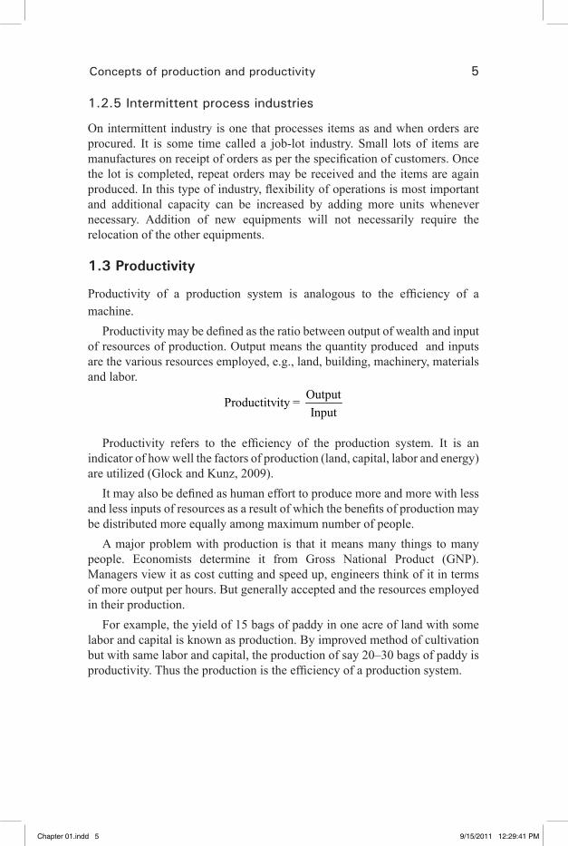
1.2.5 Intermittent process industries
On intermittent industry is one that processes items as and when orders are procured. It is some time called a job-lot industry. Small lots of items are manufactures on receipt of orders as per the specification of customers. Once the lot is completed, repeat orders may be received and the items are again produced. In this type of industry, flexibility of operations is most important and additional capacity can be increased by adding more units whenever necessary. Addition of new equipments will not necessarily require the relocation of the other equipments.
1.3 Productivity
Productivity of a production system is analogous to the efficiency of a machine.
Productivity may be defined as the ratio between output of wealth and input of resources of production. Output means the quantity produced and inputs are the various resources employed, e.g., land, building, machinery, materials and labor.
OutputProductitvity = Input
Productivity refers to the efficiency of the production system. It is an indicator of how well the factors of production (land, capital, labor and energy) are utilized (Glock and Kunz, 2009).
It may also be defined as human effort to produce more and more with less and less inputs of resources as a result of which the benefits of production may be distributed more equally among maximum number of people.
A major problem with production is that it means many things to many people. Economists determine it from Gross National Product (GNP). Managers view it as cost cutting and speed up, engineers think of it in terms of more output per hours. But generally accepted and the resources employed in their production.
For example, the yield of 15 bags of paddy in one acre of land with some labor and capital is known as production. By improved method of cultivation but with same labor and capital, the production of say 20–30 bags of paddy is productivity. Thus the production is the efficiency of a production system.
Chapter 01.indd 5 9/15/2011 12:29:41 PM
�� �� �� �� ��
6 Industrial engineering in apparel production
1.3.1 Production and productivity
Production is defined as the process or procedure to transform a set of input into output having the desired utility and quality. Production is a value-addition process. Production system is an organized process of conversion of raw materials into useful finished products.
The concept of production and productivity are totally different. Production refers to absolute output where as productivity is a relative term where in the output is always expressed in term of inputs. Increase in production may or may not be an indicator of increase in productivity. If the production is increased for the same input, then there is an increase in productivity.
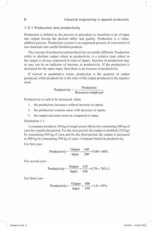
If viewed in quantitative terms, production is the quantity of output produced, while productivity is the ratio of the output produced to the input(s) used.
ProductionProductivity = Resources employed
Productivity is said to be increased, when1. the production increases without increase in inputs.2. the production remains same with decrease in inputs.3. the output increases more as compared to input.
Illustration 1.1:A company produces 160 kg of single jersey fabrics by consuming 200 kg of
yarn for a particular period. For the next period, the output is doubled (320 kg) by consuming 420 kg of yarn and for the third period, the output is increased to 400 kg by consuming 430 kg of yarn. Comment based on productivity.For first year –
Output 160Productivity = 0.80 80%Input 200
= = =
For second year –Output 320Productivity = 0.76 76%Input 420
= = = ↓
For third year –Output 400Productivity = 1.0 93%Input 430
= = =
Chapter 01.indd 6 9/15/2011 12:29:41 PM
�� �� �� �� ��

Concepts of production and productivity 7
Comment:
From the above illustration, it is clear that, for second period, though production has doubled, productivity has decreased from 80% to 76%. For the third period, production is increased by 200% and correspondingly productivity increased from 80% to 93%.
1.3.2 Benefits from increased productivity
Higher productivity results in higher volume of production and hence increased sales, lower cost and higher profit. It is beneficial to all concerns as stated below:(a) Benefits to the management:
1. More profit.2. Higher productivity ensures stability of the organization.3. Higher productivity and higher volume of sales provide opportunity
for expansion of the concern and wide spread market.4. It provides overall prosperity and reputation of the organization.
(b) Benefits to workers:1. Higher wages.2. More wages permits better standard of living of workers.3. Better working conditions.4. Job security and satisfaction.
(c) Benefits to the consumers:1. More productivity ensures better quality of product.2. It also enables reduction in prices.3. More satisfaction to consumers.
(d) Benefits to nation:1. It provides greater national wealth.2. It increases per capita income.3. It helps expansion of international market with the help of standardizes
and good quality products.4. It improves standard of living.5. It helps better utilization of resources of the nation.
Chapter 01.indd 7 9/15/2011 12:29:41 PM
�� �� �� �� ��
8 Industrial engineering in apparel production
1.4 Standard of living
Standard of living of a man is the extent to which he is able to provide for himself and his family with the things necessary for a decent and a comfortable life.
The following are the necessities for a minimum decent standard of living.1. Food – to regain energy spent in living and working2. Shelter– to give protection under healthy conditions.3. Clothing – to permit bodily cleanliness.4. Hygiene – sanitation and medical care to protect from disease and
treatment of illness.5. Security – against theft, robbery, violence, loss of work, poverty due to
illness, poverty due to old age, etc.6. Education – to develop the talents and abilities.
1.4.1 Productivity and standard of living
Each man must earn to pay for the services (hygiene, security and education) and to obtain goods (food, shelter and clothing) for himself and his family.
If the quantity of goods and services produced by any country is higher, the standard of living of the citizens of that country is also higher. Increase of employment and increase of productivity are the two ways of increasing the quantity of goods and services produced.
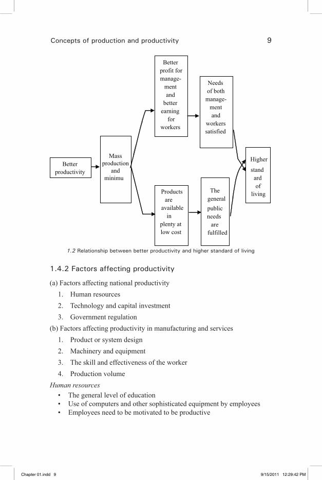
We can have more and affordable food by increasing productivity of agriculture. By increasing productivity of industry, we can provide more and inexpensive clothing. By increasing productivity and earning power, we can have more savings (after meeting expenses for food, shelter and cloth at cheaper price) and pay for more hygiene, security and education. This entire means that we have higher standard of living (Fig.1.2).
Higher productivity means that more is produced at same expenditure of resources. Efficient utilization of resources means cost reduction and savings. Part of the savings distributed among employees will increase their purchasing power and lower the prices. Therefore higher productivity leads to availability of more goods and services and higher purchasing power for the people (Kanawaty, 1992).
Chapter 01.indd 8 9/15/2011 12:29:41 PM
�� �� �� �� ��
Concepts of production and productivity 9
Better productivity
Massproduction
andminimu
Better profit for manage-
ment and
better earning
for workers
Productsare
availablein
plenty at low cost
Needs of both
manage-ment and
workers satisfied
The generalpublic needs
are fulfilled
Higher
standard of
living
1.2 Relationship between better productivity and higher standard of living
1.4.2 Factors affecting productivity
(a) Factors affecting national productivity1. Human resources2. Technology and capital investment3. Government regulation
(b) Factors affecting productivity in manufacturing and services1. Product or system design2. Machinery and equipment3. The skill and effectiveness of the worker4. Production volume
Human resourcesThe general level of education• Use of computers and other sophisticated equipment by employees• Employees need to be motivated to be productive•
Chapter 01.indd 9 9/15/2011 12:29:42 PM
�� �� �� �� ��

10 Industrial engineering in apparel production
Technology and capital investment• New technology depends on R & D• Every industry and services put new technology into use, they must • invest in new machinery and equipmentComputer aided design (CAD)•
Government regulationAn excessive amount of government regulation may have a detrimental • effect on productivity.
Product or system designR&G is a vital contributor to improved product design.• ‘Standardization’ of the product and the use of ‘group technology’ • are other design factors that make possible greater productivity in the factory.‘Value analysis’ can bring out many product design changes that • improve productivity.
Machinery and equipmentOnce the product is designed/redesigned, then how it is made offers the • next opportunity for productivity improvement. The equipment used – machines, tools, conveyors, robots, layout – all are important.CNC machines• Computer aided manufacturing (CAM)• Skill and effectiveness of the workers:• The trained and experienced worker can do the same job in a much • shorter time and with far greater effectiveness than a new one.Even the well-trained employees must be motivated to be productive • as well.
Production volumeAssume that the volume of output is to be doubled, the number of • direct workers would have to be doubled and a few indirect workers might also be needed. But there would probably not be a need for more engineers, research scientists, head quarters staff persons or other support personnel. So if the output is doubled, the productivity of these support people is in effect doubled.
Economic growthThe economic growth of a country depends on the national productivity. • The national productivity will automatically increase if productivity of individual industrial and productive unit increases, we shall consider the factors that affect the productivity of an individual unit. They are as follows:Land and building•
Chapter 01.indd 10 9/15/2011 12:29:42 PM
�� �� �� �� ��

Concepts of production and productivity 11
Material• Machinery and equipment• Men (Labor)•
1.5 Productivity measures
1.5.1 Labor productivity
The resource inputs are aggregated in terms of labor hours. Hence this index is relatively free of changes caused by wage rates and labor mix. By improving methods of work (eliminating unnecessary movement, etc.) the output of a worker can be increased. (a) In terms of hours:
Production in standard hoursPr oductivityActual man hours
=
(b) In terms of money:
( )Total cost or sale value of outputPr oductivity
Number of workers=
The productivity of labor can be increased by increasing efficiency of labor, reducing idle time.
For example, let us take a turner who was producing 20 pieces an hour and the same turner, by the improved methods of doing work is able to produce 25 pieces an hour. Then productivity has increased by [(25 − 20)/20] × 100 = 25%.
1.5.2 Machine productivity
By use of sophisticated modern machines, better method of manufacture and reducing idle time of machines, the number of pieces (items) produced by a machine per hour can be increased.
Output in standard hoursPr oductivityActual machine hours
=
For example, let us assume a machine was producing only 100 pieces per working day of 8 hours. The machine tool has fitted with a better tool that permitted more depth of cut and higher cutting speed. As a result the output from the machine increased to 130 pieces in a day of 8 hours. In this case, the productivity has increased by [(130 − 100)/100] × 100 = 30%.
Chapter 01.indd 11 9/15/2011 12:29:42 PM
�� �� �� �� ��
12 Industrial engineering in apparel production
Machines and equipments necessary for the operational activities of the enterprise, including those intended for transport and handling, heating or air conditioning, office equipment, computer and the like.
1.5.3 Material productivity
Materials that can be converted into products to be sold, both as raw materials or auxiliary materials such as solvents or other chemicals and paints needed in the process of manufacturing and packaging material. By product design and by use of skilled workmen, material wastage can be greatly reduced. Thus from a given quantity of material more number of pieces can be produced.
For example, a worker may cut 10 metal discs from a given length of metal plate per hour. A skilled worker by improving the method can cut 12 pieces in one hour. Then in this case, the productivity of material has increased by [(12 − 10)/10] × 100 = 20%.
Material costProductivity = Number of units produced
Weight of productProductivity = Weight of raw material
1.5.4 Capital productivity
Several formulations are possible for this measure. In one, the resource inputs may change during the period of depreciation, in another, the input may be the book value of capital investment.
1.5.5 Energy productivity
The resource input is the amount of energy consumed in kilowatts.
1.5.6 Land productivity
For example, let us assume that the yield from one acre of land cultivated is 15 bags of paddy. One can cultivate two acres of land and get yield of 30 bags of paddy. In this case, only production is increased, productivity remains the same. But by using better seeds, better methods of cultivation, if the yield from the same one acre of land is increased from 15 bags to 20 bags of paddy, then in this case the productivity is increased by [(20 − 15)/15] × 100 = 33%.
On industrial side, the productivity of land and buildings is said to have increased if the output of goods and services within that area is increased.
Chapter 01.indd 12 9/15/2011 12:29:42 PM
�� �� �� �� ��
Concepts of production and productivity 13
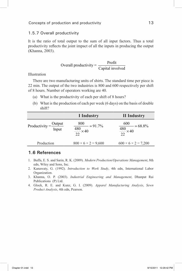
1.5.7 Overall productivity
It is the ratio of total output to the sum of all input factors. Thus a total productivity reflects the joint impact of all the inputs in producing the output (Khanna, 2003).
ProfitOverall productivity = Capital involved
Illustration There are two manufacturing units of shirts. The standard time per piece is
22 min. The output of the two industries is 800 and 600 respectively per shift of 8 hours. Number of operators working are 40.
(a) What is the productivity of each per shift of 8 hours?(b) What is the production of each per week (6 days) on the basis of double
shift?
I Industry II IndustryOutputProductivity =Input
800 91.7%480 4022
=×
600 68.8%480 4022
=×
Production 800 × 6 × 2 = 9,600 600 × 6 × 2 = 7,200
1.6 References
1. Buffa, E. S. and Sarin, R. K. (2009). Modern Production/Operations Management, 8th edn, Wiley and Sons, Inc.
2. Kanawaty, G. (1992). Introduction to Work Study, 4th edn, International Labor Organization.
3. Khanna, O. P. (2003). Industrial Engineering and Management, Dhanpat Rai Publications (P) Ltd.
4. Glock, R. E. and Kunz, G. I. (2009). Apparel Manufacturing Analysis, Sewn Product Analysis, 4th edn, Pearson.
Chapter 01.indd 13 9/15/2011 12:29:42 PM
�� �� �� �� ��
15
2Role of apparel engineering
2.1 Introduction
Engineering makes things useful to man. Frederick Taylor and Frank Gilberth were the originators of many of the practices and concepts used today in twentieth century (Amar, 1920).
Industrial engineering is the engineering approach applied to all factors, including the human factor, involved in the production and distribution of products and supplies.
Three main objectives of industrial engineering is to findthe best way to do a work.• the time required to do it.• the way to measure results.•
The industrial engineering is necessary in apparel industry, because without thorough information regarding the plant, manager is almost powerless to take action.
2.1.1 Work study
Work study covers many management techniques, but it is defined broadly as:Method study – The systematic recording, examination and improvement • of doing work in order to develop a better method. Work measurement – It is the name given to various techniques used to • determine the time necessary for a trained worker to carry out a specific job, either at a “standard pace” or at “incentive pace” to an acceptable degree of quality.
2.1.2 The role of work study as a means of increasing productivity
Work study has a direct relationship with productivity as it is used most frequently to increase the quantity produced from a give quantity of resources with little or no capital investment (Solinger, 1980).
Chapter 02.indd 15 9/15/2011 12:31:11 PM
�� �� �� �� ��
16 Industrial engineering in apparel production
2.1.3 The benefits of work study
Work study is thus a service to management and supervision and will ensure the following benefits:
It is a means of raising the productive efficiency of a factory or • organization with little or no capital investment.It is systematic and ensures that no factor is overlooked.• It is the most accurate means of setting standards upon which production • planning and control can take place.The resultant savings start at once and continue for as long as the • operations continue in the improved form.It is a “tool” which can be applied everywhere.• It is one of the most penetrating tools of investigation available to • management.To achieve the full benefit of work study, it should be applied in all • areas of an organization and continuously followed.The full effect of work study will only be felt in an organization when • all employees become accustomed to an attitude that:No tolerance to waste in any form, whether material, time effort or • human ability.The refusal to accept without question that things should be done in a • certain way because it is the way it has always been done.
2.2 Apparel engineering
Simple industrial engineering applied specifically to the apparel industry.Main activities of an industrial/apparel engineer
Plant layout• Production flow system• Machines and adjustments• Operator performance• Operator training• Production control system• Cutting room• Quality control•
Chapter 02.indd 16 9/15/2011 12:31:11 PM
�� �� �� �� ��
Role of apparel engineering 17
Distribution• Payroll system / incentives• Plant safety• Maintenance•
2.3 Methodology
2.3.1 Standardization
Supervisors will always appreciate the need for standard condition in managing a department efficiently. Higher amount of confusion would result if the work is not standardized.
Some case studies are as follows: If each sewing operator performed their work in different ways.• If each sewing operator use different type of machine for same type of • work.If payroll department changed its method of paying employees each • week.If quality specifications changed every day.•
Effective supervision would be impossible without standardization of methods, equipments and conditions. Engineering helps to standardize.
2.3.2 Production scheduling
Without a firm production schedule the department’s ability to produce • efficiently is hampered.Impossible to plan the quantum of work to be loaded.• It would result in the delay in delivery or more idle time.• In order to schedule work accurately, someone needs to know how long • it takes to go through each operation.Engineering data help to prepare a firm production schedule.•
2.3.3 Fair payment to the employees
To ensure fair payment to the employees.• Need to know the value of the work produced by an employee.• Need to measure the work. • Compare the employee’s contribution. •
Chapter 02.indd 17 9/15/2011 12:31:11 PM
�� �� �� �� ��

18 Industrial engineering in apparel production
2.3.4 Prevention of any system failure
Any attempt to run any department or firm without standardized conditions, without production schedule and without fair payment to employees is doomed to chaos and failure.
Without having someone performing the above functions, it would be impossible to operate for very long.
2.4 Benefits of engineering
Work simplificationEffort to make the work simpler.• Kill the skill of the work enabling a medium skilled employee to perform • efficiently. (Higher and consistent output)
Increase in productivityThe ability to produce more within the same amount of time is company’s • insurance for survival.Results increase in capacity, and thus, scope for getting more orders.• Avoids overtime cost. •
Increase in profitsTimely deliveries and increase in the quality and quantity of the product • delivered results in higher profits.Ensures smooth operation functions without a break due to continuous • orders.
Increase in earningsIncrease in profit will enable the owners and stock holders to reward all • the employees involved in the industry.Will enable for further expansion thus creating more jobs and improving • the economy of the area in which the company is located.
2.5 Tools and techniques for apparel engineering
2.5.1 Magnitude of operations
Expensive fabric, industrial machinery, intense labor, electricity and floor space are all used to produce garments ordered by a customer. But executives do not realize the magnitude of the operations they manage on the shop floor.
Labor – If an executive is supervising a sewing line which has total • of 50 workers (40 operators and 10 others), he/she is managing the resources which are equivalent to Rs. 6730/- per day , Rs. 1,75,000/- per month and Rs. 21,00,000/- per year which is huge.
Chapter 02.indd 18 9/15/2011 12:31:11 PM
�� �� �� �� ��
Role of apparel engineering 19
Industrial machinery – If an executive is supervising a sewing line • which has 45 sewing machines, he or she is managing the resources which is equivalent to Rs. 17,30,000/- which is huge.Expensive fabric – If an executive is supervising a line producing • around 10,000 pieces per month, then the value of the fabric may be Rs. 20,00,000/- which again is very huge.
So, the magnitude of operations handled by an executive is really huge. This book provides knowledge of tools and techniques that will help to
approach a situation in an effective and scientific way.
2.5.2 Tools
The most common tools used by an apparel engineer are stop watch and calculator.
2.5.3 Techniques
(i) Method analysisThe procedure of studying methods used to determine the best way of job.The apparel engineer studies not only the way in which the operator handles
the work, but also the machines used, the layout of the workstation and the work aids used. The whole purpose of a method analysis is to find a better way to do a job.
Some of the more common ways of performing a method analysis are as follows:
(a) Observation – Look at method over and over.(b) Hand chart – Write description of simultaneous movements of left and
right hand.(c) Principles of motion economy – Compare motions in use with a
checklist of proven economical motions.(d) Slow motion analysis – Use either motion pictures or video tapes to
slow down activities for better observation.One of the most important traits of an effective apparel supervisor is the
ability to recognize good and bad methods among operators and to correct when necessary.(ii) Time study
This is the most common technique used by an engineer to set targets. It helps in setting and developing standards in terms of allowed time to produce a certain number of units in a normal workday.
Chapter 02.indd 19 9/15/2011 12:31:11 PM
�� �� �� �� ��

20 Industrial engineering in apparel production
(iii) Capacity studies and strength analysisA capacity study is similar to a time study but here it is done to find the
operators level of performance. This can be combined with a strength analysis, to determine the wastage of potential we are having, not only with one operator, but also with a line, batch or factory.(iv) Follow-up study
A follow-up study is a means of measuring exactly what is happening performance-wise to an individual operator or a group of operators. In making the follow-up study, the engineer records operator performance and also measures any delays that hamper performance.(v) Bundle diagnosis
This is a tool used to determine the specific areas where the operators are weak or strong, to focus the effort of training in those particular areas in which she is not at the required level. It measures the performance of the operator at every stage during the performance.(vi) Incentive plans
The development of a fair incentive plan for operators is a basic function of an apparel engineer. The most common form is a straight piecework system, where the operator’s pay is based entirely on what the operator produces. There are cases, however, where such a plan might not be fair to the operator. For example, utility operator’s performance in each operation would not be high due to frequent changes. For this reason, various types of split incentive plans can be used. Most operators can master the simple arithmetic processes of applying any wage incentive formla.(vii) Drill training
Many companies place their operator training programs under the engineering function, especially when some form of drill training is used. This is a system in which particular jobs to be taught are analyzed and broken down into job parts. The operator learns the job of one part at a time, and this enables her to learn faster than if she tries to learn the whole job at once. It is basically based in learning the different skills required to perform one complete operation.(viii) Statistical quality control
SQC is a means of sample inspection that is designed to measure and control quality without having to inspect each and every unit produced.(ix) Scheduling systems
Engineers are becoming more and more involved with the development of systematic approaches to production scheduling and work process control (Seminar SCT, 2010).
Chapter 02.indd 20 9/15/2011 12:31:11 PM
�� �� �� �� ��

Role of apparel engineering 21
2.6 Role of industrial engineer
Each executive/supervisor has eight areas of responsibility that need to be managed.
1. Safety2. Line balancing3. Quality – operation control4. Training – how to train new employees5. Operator output – maintains high output and improves abilities of those
with low output.6. Loss control – minimize off-standard loss7. Waste control – in materials, supplies and machinery8. Standard conditions – in the workplace, in sewing method, in the
machines
2.6.1 Executive as a leader
A good way of showing leadership is to be a good example for others.Every executive/supervisor represents the company and any of his/her
actions are an extension of the Maintenance• Quality work• Productivity•
Authority is usually earned but from the beginning, executives will be assigned to do the following tasks that require authority:
1. Employee transfers between the operations2. Assigning of off-standard tasks3. Overtime planning4. Rejecting defective product5. Disciplinary actions6. Recommendations for dismissalEmployee respect will depend on how an executive/supervisor acts
as a leader and uses his/her authority to benefit all employees in his/her department.
Chapter 02.indd 21 9/15/2011 12:31:11 PM
�� �� �� �� ��

22 Industrial engineering in apparel production
2.6.2 Obligations of an executive
To manage effectively, an executive/supervisor should identify and divide his/her obligations to primary and secondary.
He/she must first take care of primary obligations adequately. In some cases this means that secondary obligations will have to be delegated to someone under the supervisor’s authority.
2.6.3 Primary obligations
Provide safety• Plan and balance production lines• Control quality• Develop employees• Follow up on low output employees• Material utilization• Discipline•
2.6.4 Secondary obligations
Bundle handling and movement• Adjustments to machines• Distributes supplies• Handle parts that needs reprocessing• Samples• Maintenance• House keeping• Miscellaneous•
2.6.5 Daily activities of an executive
First thing in the morningArrive early• Greet arriving employees• Encourage them to start work early• Check attendance• Make adjustments to balance the line according to absence.•
Chapter 02.indd 22 9/15/2011 12:31:11 PM
�� �� �� �� ��

Role of apparel engineering 23
Attend production meeting and discuss yesterday’s results and today’s • targets and plans.Plan•
How to increase efficiency ºHow to improve outgoing quality ºHow to prepare for routine problems or problems that might arise. º
2.6.6 During the day
Measure the target vs. actual output every hour• Check quality level• Check inline and end line quality reports• Discuss with quality inspectorsPerform quality drill• Work with low output operators• Check proper method• Motivate and empower operator• Follow up on new operators in training • Follow up on operator in re-training• Identify the bottle neck operations and balance accordingly• Provide immediate and continuous follow-up to repairs• Monitor and follow up on bundle tracking and outgoing bundles.• Authorize any off-standard “clock-out”• Order supplies and material for production•
2.6.7 At the end of the day
Make sure the operators have turned off their machines, cleaned their • work area, kept a piece of fabric under the pressure foot, and covered their machine.Check and authorize the production work sheet• Organize production sheets and check the last hour production with the • sheet.Review the hourly production report and WIP report• Analyze the next day’s needs and take notes for implementation• Calculate the next day’s initial inventory according to production • information
Chapter 02.indd 23 9/15/2011 12:31:11 PM
�� �� �� �� ��
24 Industrial engineering in apparel production
2.6.8 WeeklyReview the capacity studies of low output operators• Plan operator cross training to solve balancing problems•
2.6.9 As and when required Resolve any operator efficiency problems• Follow up and motivate new employees• Work out quality problems with quality inspectors• Work out problems with operators; review the proper method with them • when necessary
2.7 Pre-production activities of a supervisorAttend the pre-production meeting along with the merchandisers and • buyer representatives.Receive the production package, which mainly includes the sealed • sample with sealer comments, tech pack, approved trim cards, order quantity (color/size wise) and delivery details.Co-ordinate with the R&D on doing the risk analysis.• Work with the IE department on special machines, folders, attachments • and get the machinery layout and targets.In consultation with the sampling department find out the critical areas • which need special attention.Discussions with the quality department on understanding the buyer • requirements and the quality parameters to be followed by the factory. Make mock ups for the critical operations.Insist on the markings and notches, required from the cutting • department.Get the loading and production plan from the PPC• department. Decide the machine and operator allocation with the help of IE and • maintenance departments.Evaluate the construction, workmanship and quality of the pilot run and • then proceed with the bulk. Repairs to be cleared before the new style/color output.• All remaining trims/accessories and cut panels to be returned to the • concerned department, immediately after the style completion. Make the style completion/closure report. •
Chapter 02.indd 24 9/15/2011 12:31:11 PM
�� �� �� �� ��

Role of apparel engineering 25
Review the quality of the goods getting packed.• Take part in final inspections.•
2.7.1 Supervisory cost control
Direct labor cost is often used as a key measurement of a firm’s productivity.3
The control and non-control of departmental costs is reflected in every action a supervisor takes. The Major cost of this industry is cost of labor (Seminar SCT, 2010).
So cost is directly related to operator performance, intelligent handling of production flow and also efficient utilization of labor.
2.7.2 Major areas of excess costs (direct labor)
(i) Operator performanceSupervising methods
Understand thoroughly the best method to use on each operation and • ensure that the workers use them.Methods need to be standardized and these standard practices should • not be changed unless there is a requirement from customer side.When methods are changed, make certain that operators are instructed • properly and follow-up to make certain that the instructions are followed. Whenever there is change in design of the product, operations and • methods should be worked out and approved on one or two bundles before the balance bundles are processed. This method will often save a bottleneck in production later.Ensure layout is established along with IE before the start of the style.• Operator should be allocated to each operation based on the skill.• Know the possibilities and limitations of the machine used and see that • proper speed, stitches, folders, attachments, etc., are used. Ensure the machine is set up properly prior to sewing/assigning operators.
Waste of timeThe greatest waste of all is the waste of time, because it wastes machine
and manpower and lowers the productive capacity of the department.Some of it may be intentional, deliberate loafing, excessive conversation or
unnecessary absence from work. Much of it, however, is unintentional-time which is improperly used, resulting in more time and energy being consumed than is necessary for the amount of work being done.
Chapter 02.indd 25 9/15/2011 12:31:11 PM
�� �� �� �� ��
26 Industrial engineering in apparel production
When the waste of time is intentional, it means that the supervisor does not control the workers and when it is unintentional, it means that the workers are not properly trained or supervised in methods or the flow of production needs closer attention.(ii) Production flow Maintaining production
See that there is adequate supply of work between two operations to • prevent operators from slowing down or waiting for work.Watch for “drops” in production on each operation because of • absenteeism, capacity or other reason, and immediately take the necessary steps to bring it back to normal before the subsequent operations get affected.“Switch” operators as and when required to maintain balance. Anticipate • “imbalance” and take counter-measures to assure maximum production without transferring operators, if possible. See that necessary supplies, equipment and information for jobs are at • hand before they are needed.Keep informed as to the work schedule for your section and see that • cuts and materials are stored in proper place before it is needed.All re-cuts and repairs should be made promptly so that “bundles” will • be completed on schedule and there is no scope of unfinished garments lying in the line after completion of style.Do not change operator from job to job to balance frequently. Balancing • should be done using utility operator so that regular operator doesn’t lose efficiency.Keep in close touch with trainers concerning the progress of learners, so • that learners can contribute to the increase in production.See that any one operator transferred to other operation or working on • unmeasured work uses the best methods and extends a reasonable effort. This rule applies to utility operators, shuttle operators and re-trainees.Parts to be sewn should fit without having to be cut, trimmed or • stretched by the operator. Any need for trimming or stretching should be reported.
2.7.3 Other areas of excess cost
Supervising qualityA supervisor has the responsibility of good workmanship. Just as the •
Chapter 02.indd 26 9/15/2011 12:31:12 PM
�� �� �� �� ��

Role of apparel engineering 27
quality of a worker can be measured by the quality of her work, the quality of a supervisor is measured by the quality of work produced in her section. Watchfulness is the key for good quality.Supervisor has to make the worker understand the quality requirements. • Until and unless the worker understands the requirements you don’t get the required quality. So, quality motto should be “Control at the Needle Point”.When changes are made in materials, be watchful that folders, feeds, • stitches, etc., are working properly with the new material.When the flow of work causes idle period in the worker’s time and she • has time to think of things outside her work, the average quality work will be lower than when ample flow of work is coming through. Be watchful for poor quality when this condition exists.Sometimes the poor condition of machines or equipment is the cause of • poor quality. Checking of machines should be done regularly and often enough to maintain them in good condition.The supervisor’s own attitude toward the job will be a big influence. If • her manner indicates that she isn’t much concerned with the quality of an operation, then the worker isn’t likely to be much concerned.
Wastage of materialsThere should never be any wastage of power, light, oil, water, thread, • needles or any other supply. Proper storage facilities for some of these items and keeping a watch on these facilities will help to conserve them.Surplus accessories such as twill tape, hook and eye, velcro, etc., should • be returned to stock and not allowed to accumulate in bins or work boxes at the machine.Re-cuts should be used sparingly. Review re-cut ordering procedure. • When stitching needs to be re-opened, the supervisor should see to it • that the method used will not damage the part.
Work forceIt is important for the supervisor to continually look ahead and foresee • the relation between number of workers needed at present and those needed for future production.Anticipate the need for more workers due to change in style or production • requirements and take the necessary measures to provide them as far ahead of time as possible so that they will be properly trained when needed.
Chapter 02.indd 27 9/15/2011 12:31:12 PM
�� �� �� �� ��

28 Industrial engineering in apparel production
The supervisor should report possible “quits” to the production manager • as soon as she learns of them so that measures may be taken to train someone for the job before the quit occurs.Labor turnover is an important element in maintaining an adequate • working force. Careful thought should be given to the subject and this effect it has on the cost of operations.Interview each worker who quits in order to obtain first-hand information • about the reason for her quitting.Be careful in exercising your authority to discipline or discharge • workers.On the other hand, remember that everyone is not suited for this type • of work. Be able to detect the “Square Pegs and do not waste time to fit them into round holes”. These workers are the ones who in spite of everyone’s effort including their own develop to about 75% and then stop. Discussing such problems with your assistants and supervisors will bring out the facts and help you arrive at the best decision.
Working conditionsWork atmosphere should be good, for example, proper lighting, fans, • etc., are properly regulated at all times for the comfort of the workers. Restrooms, drinking water area, etc., must be kept clean. Aisles and spaces around the machines should be kept clear and equipment and bins should be cleaned regularly.Good housekeeping can’t be accomplished if there is no combined • effort from workers. You must secure the co-operation of the workers; set a good example for them to follow.Guard against workers adopting practices that are harmful to good order. • These practices are often due to the disregard of work rules, which she/he thinks is unimportant. She will begin to put finished work material, thread, etc., in some place other than the right place. Continued neglect quickly forms a bad work habit. Constant vigil by supervisor only will lead to the correction of such conditions before habits are formed. It will make things easier for everyone and it will not put a severe strain upon good working relations between the supervisor and her workers (Seminar SCT, 2010).
2.8 References
1. Amar (1920). The Human Century, George Routledge and Sons.2. Solinger, J. (1980). Apparel Manufacturing Handbook, Analysis, Principles and
Practice, Van nostrand Reinhold Company.3. Seminar SCT (2010). Technical workplace skills for the garment industry, Sona School
of garment and fashion technology.
Chapter 02.indd 28 9/15/2011 12:31:12 PM
�� �� �� �� ��

29
3Method analysis
3.1 Definition
Method analysis is the logical recording and significant examination of ways of doing things in order to make improvements.
Method analysis can also be defined as “systematic recording and critical examination of existing and proposed ways of doing work as means of developing and applying easier and more effective method and thereby reducing cost” (Kanawaty, 1992).
In this field, pioneering work was done by Frank B. Gilbreth and his wife Lillion M. Gilbreth, around 1910, with the name of motion study. Frank Gilbreth, the real founder of motion study as science, defined motion study as “the science of eliminating wastefulness resulting from ill-directed and in efficient motions”. The aim of motion study is to find the scheme of least wastage of labor.
“Method Study” is the careful writing down of how a job is done, checking the way it is done, and trying to find a better or simpler way of doing the job.
3.1.1 Objectives of method analysis
1. To train the individual worker in its practice as per standardized method.
2. To standardize the method, obtained after conducting the motion study.
3. To reduce fatigue and boredom of work by avoiding unnecessary movements.
4. To improve the design of workplace layout. 5. To have more effective utilization of materials, machines and work
force.6. To find the best way of doing a job.7. To eliminate wastage of time and labor.
Chapter 03.indd 29 9/15/2011 12:31:27 PM
�� �� �� �� ��

30 Industrial engineering in apparel production
3.1.2 Basic procedure for method analysisMethod study steps
Select• the job to be studied by.Record• every detail about the job.Examine• all the details by asking why?who?where?what?Consider• alternatives for improvement and develop the most suitable.Define• all jobs other than those performed on standard machine tools or specialized machine where the process and methods are virtually controlled by the machine.Install• new method by making sure it is understood.Maintain• the new method by continually checking that it is still being performed correctly.
3.1.3 Selection of workThere are three factors that should be kept in mind when selecting a job.
1. Economic or cost-effective considerations2. Technical considerations3. Human considerations
3.1.4 Economic considerations
It is obviously a waste of time to start or to continue a long investigation if the economic importance of a job is small or if it is one that is not expected to run for long.
1. Profit-generating or costly operations.2. Operations which produced large amount of scraps or wastes.3. Bottle neck operations which are holding up other production
operations.4. Lengthy operations that consumes a great deal of time.5. Operations involving repetitive work using a great deal of labor.6. Movements of material over long distances between work stations.7. Operations those require repeated handling of materials.
One of the easiest techniques that can be used to identify key operations is the Pareto analysis (some time also referred to as the ABC analysis).
3.1.5 Technical or Technological considerationsOne of the important considerations is the desire by management to acquire more advanced technology, whether in equipment or in processes. Thus
Chapter 03.indd 30 9/15/2011 12:31:27 PM
�� �� �� �� ��
Method analysis 31
management may want to computerize its office paperwork or its inventory system or to introduce automation in the production operations.
3.1.6 Human considerations
Certain operations are often a cause of dissatisfaction by workers. They may induce fatigue or monotony or may be unsafe or clumsy to operate. The level of satisfaction should point to a need for method study. Thus an operation which may be perceived as effective by management may generate a great deal of resentment by the work force. If such operations are addressed by work study specialists as part of an overall work study programme, the benefits of work study can become more apparent to the workforce (Khanna, 2003).
3.2 Recording the methodAfter selecting the job to be studied, the next set is to record all the facts relating to the existing method. The success of the whole procedure depends on the accuracy with which the facts are recorded, because they will provide the basis of both the critical examination and the development of the improved method. When methods are studied, they cannot be viewed in isolation because each operation is affected by the operation before it and the one after it.2
The useful way of recording is to write them down. Unfortunately, this method is not suited to recording the complicated processes, which are so common to modern industry. This is particularly so when an exact record is required of every minute detail of a process or operation.
To overcome this difficulty other techniques or tools of recording have been developed, so that detained information may be recorded precisely and at the same time in standard form, in order that it may be readily understood by all method study persons.
The most commonly sued recording techniques are charts and diagrams. There are several types of these are available each bearing its own advantages.
The most commonly used method analysis charts and diagram.Charts: Outline process chart
Flow process chart – worker type Flow process chart – material type Flow process chart – equipment type Two-handed process chart Multiple activity charts
Chapter 03.indd 31 9/15/2011 12:31:27 PM
�� �� �� �� ��

32 Industrial engineering in apparel production
SIMO chartDiagrams: Flow diagram String diagram Cycle graph, Chronocyclegragh Travel chart________________________________________________________________________Processchartsymbols
(a) Operation – Any operation for making altering or changing the job is
said to be an operation.
(b) Inspection – Checking the quality and quantity.
(c) Transport – Movement or travel of the job.
(d) Delayortemporarystorage – Breakdown, interface or time required
for some adjustments. A temporary halt in the process.
(e) Storage – Keeping, holding and storing the job and other things.
(f) Operationandinspection– Set of tool, e.g., powder milk tin is being
weighed (inspection) as it is filled.
(g) Operationcumtransport– Articles are being painted as they are
transported by the chain conveyor.
Chapter 03.indd 32 9/15/2011 12:31:29 PM
�� �� �� �� ��
Method analysis 33
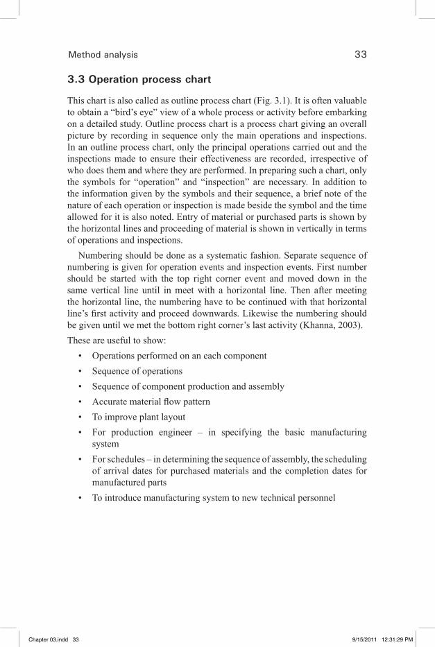
3.3 Operation process chart
This chart is also called as outline process chart (Fig. 3.1). It is often valuable to obtain a “bird’s eye” view of a whole process or activity before embarking on a detailed study. Outline process chart is a process chart giving an overall picture by recording in sequence only the main operations and inspections. In an outline process chart, only the principal operations carried out and the inspections made to ensure their effectiveness are recorded, irrespective of who does them and where they are performed. In preparing such a chart, only the symbols for “operation” and “inspection” are necessary. In addition to the information given by the symbols and their sequence, a brief note of the nature of each operation or inspection is made beside the symbol and the time allowed for it is also noted. Entry of material or purchased parts is shown by the horizontal lines and proceeding of material is shown in vertically in terms of operations and inspections.
Numbering should be done as a systematic fashion. Separate sequence of numbering is given for operation events and inspection events. First number should be started with the top right corner event and moved down in the same vertical line until in meet with a horizontal line. Then after meeting the horizontal line, the numbering have to be continued with that horizontal line’s first activity and proceed downwards. Likewise the numbering should be given until we met the bottom right corner’s last activity (Khanna, 2003). These are useful to show:
Operations performed on an each component• Sequence of operations • Sequence of component production and assembly• Accurate material flow pattern• To improve plant layout• For production engineer – in specifying the basic manufacturing • systemFor schedules – in determining the sequence of assembly, the scheduling • of arrival dates for purchased materials and the completion dates for manufactured partsTo introduce manufacturing system to new technical personnel•
Chapter 03.indd 33 9/15/2011 12:31:29 PM
�� �� �� �� ��

34 Industrial engineering in apparel production
1
2
3
1
4
5
6
Marking
Cutting
Inspection
Numbering
Bundling
Ticketing
3.1 Outline process flow chart
Chapter 03.indd 34 9/15/2011 12:31:29 PM
�� �� �� �� ��

Method analysis 35
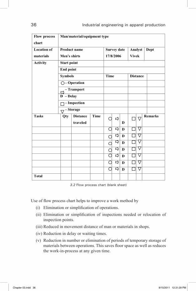
3.4 Flow process chart
This is a graphical representation of operation, transportation, inspection, delays and storage occurring during production. This also gives the information regarding distances moved and time required for different items (Fig. 3.2).
After preparing flow process chart, a process or job can be analyzed step by step. Activities can be eliminated in some cases, combined in others, rearranged for more effective processing or simplified. The proposed new method is drawn in the chart.Types of charts:(a)Flowprocesschart–ProductAnalysisThis is a graphic representation of different steps involved in performing the work required to convert a product from one stage to another.(b)Flowprocesschart–ManAnalysisThis is a graphic representation of different steps; a person performs when doing a job and his movement from one place to another in performing that job.(c)Flowprocesschart–EquipmentAnalysisA flow process chart records how the equipment is used.
Until, unless clearly mentioned flow process chart refers to that of flow process chart based on product (material) analysis.
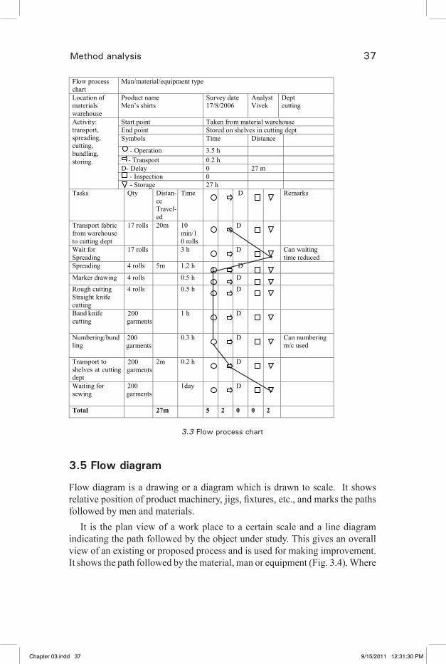
The starting point of the activity is selected and is recorded briefly on the first line of the chart. Every step or activity which occurs is then listed in proper sequence and with an accurate but brief description. The transportation distance, the quantity of materials handled and the time each activity taken are very useful information which may be given on the chart. A summary giving total of each type of details, the distance traveled and the time consumed should also be given on the chart (Fig. 3.3). This information is very useful to the management for comparing one method with other methods (Khanna, 2003).
Chapter 03.indd 35 9/15/2011 12:31:29 PM
�� �� �� �� ��
36 Industrial engineering in apparel production
Flow process
chart
Man/material/equipment type
Location of
materials
Product name
Men’s shirts
Survey date
17/8/2006
Analyst
Vivek
Dept
Activity Start point
End point
Symbols Time Distance
– Operation
– Transport
D – Delay
– Inspection
– Storage
Tasks Qty Distance
traveled
Time
D
Remarks
D
D
D
D
D
D
D
Total
3.2 Flow process chart (blank sheet)
Use of flow process chart helps to improve a work method by(i) Elimination or simplification of operations.(ii) Elimination or simplification of inspections needed or relocation of
inspection points.(iii) Reduced in movement distance of man or materials in shops.(iv) Reduction in delay or waiting times.(v) Reduction in number or elimination of periods of temporary storage of
materials between operations. This saves floor space as well as reduces the work-in-process at any given time.
Chapter 03.indd 36 9/15/2011 12:31:29 PM
�� �� �� �� ��
Method analysis 37
Flow process chart
Man/material/equipment type
Location of materials warehouse
Product name Men’s shirts
Survey date 17/8/2006
Analyst Vivek
Dept cutting
Activity: transport, spreading, cutting, bundling, storing.
Start point Taken from material warehouse End point Stored on shelves in cutting dept Symbols Time Distance
- Operation 3.5 h - Transport 0.2 h D- Delay 0 27 m - Inspection 0 - Storage 27 h
Tasks Qty Distan-ce Travel-ed
Time D Remarks
Transport fabric from warehouse to cutting dept
17 rolls 20m 10 min/10 rolls
D
Wait for Spreading
17 rolls 3 h D Can waiting time reduced
Spreading 4 rolls 5m 1.2 h D
Marker drawing 4 rolls 0.5 h D
Rough cutting Straight knife cutting
4 rolls 0.5 h D
Band knife cutting
1 h D
Numbering/bundling
0.3 h D Can numbering m/c used
Transport to shelves at cutting dept
2m 0.2 h D
Waiting for sewing
200 garments
200 garments
200 garments
200 garments
1day D
Total 27m 5 2 0 0 2
3.3 Flow process chart
3.5 Flow diagram
Flow diagram is a drawing or a diagram which is drawn to scale. It shows relative position of product machinery, jigs, fixtures, etc., and marks the paths followed by men and materials.
It is the plan view of a work place to a certain scale and a line diagram indicating the path followed by the object under study. This gives an overall view of an existing or proposed process and is used for making improvement. It shows the path followed by the material, man or equipment (Fig. 3.4). Where
Chapter 03.indd 37 9/15/2011 12:31:30 PM
�� �� �� �� ��
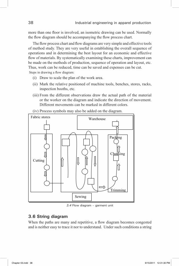
38 Industrial engineering in apparel production
more than one floor is involved, an isometric drawing can be used. Normally the flow diagram should be accompanying the flow process chart.
The flow process chart and flow diagrams are very simple and effective tools of method study. They are very useful in establishing the overall sequence of operations and in determining the best layout for an economic and effective flow of materials. By systematically examining these charts, improvement can be made on the methods of production, sequence of operation and layout, etc. Thus, work can be reduced, time can be saved and expenses can be cut. Steps in drawing a flow diagram:
(i) Draw to scale the plan of the work area.(ii) Mark the relative positioned of machine tools, benches, stores, racks,
inspection booths, etc.(iii) From the different observations draw the actual path of the material
or the worker on the diagram and indicate the direction of movement. Different movements can be marked in different colors.
(iv) Process symbols may also be added on the diagram.
Fabric Fabric stores
Cutting
Packing
Checking
Trimming
Warehouse
Sewing
3.4 Flow diagram – garment unit
3.6 String diagramWhen the paths are many and repetitive, a flow diagram becomes congested and is neither easy to trace it nor to understand. Under such conditions a string
Chapter 03.indd 38 9/15/2011 12:31:30 PM
�� �� �� �� ��

Method analysis 39
diagram is preferred. String diagram is a model or a scale plan of the shop in which every machine or equipment is marked and a peg or pin is struck by or in the area representing a facility. A continuous colored thread or string traces the path taken up by the materials or workers while performing a particular operation.
It is a special type of flow diagram, generally prepared when the movements involved (of men, material or equipment) are large and cannot be comprehensively recorded by flow diagram.
Examples of situations where string diagrams find applications are as follows: material handling man attending to the requirements of a group of workers; a store man issuing raw materials and tools in a production shop; a nurse carrying out routine work of checking temperature, giving medicine and serving meal to patients in hospitals.Construction
(i) Draw the scale layout of the shop area mark various features, such as machinery, work stations, store, etc. (Fig. 3.5).
(ii) Mount this scaled drawing on a soft board and strike pins or pegs at all the places which form the path of the workers and materials. More pegs may be struck in between the facilities as to trace more or less, the actual path of men and materials.
(iii) A continuous colored unstretchable string, taken from the first to the last peg, is wound to mark the path followed by workers or materials.
Uses(i) It is very useful in dealing with complex movements and plant layout
and design problem.(ii) Indicates clearly, back tracking, congestion bottlenecks and over- and
under-used paths on the shop floor (Fig. 3.6).(iii) Measures the distances involved and points out whether a work station
is suitably located.(iv) Traces modifications in existing path.
DrawbacksIf the workers or materials move in some irregular or curvilinear path, it is
not possible to trace exactly the same on the string diagram.
Chapter 03.indd 39 9/15/2011 12:31:30 PM
�� �� �� �� ��

40 Industrial engineering in apparel production
Set sleeve
Fronts
Backs
Inspection
Set shoulder
Set collar
Fini
shin
g
Inspection Start
End
3.5 String diagram (Existing layout)
3.7 Travel chart (From – To chart)
The chart which gives an estimate about the amount of material handling between various work stations is known as travel chart. The amount of travel depends upon the frequency of movements between sections of departments. A travel chart helps improving the existing plant layout.
A travel chart is advantageous because it brings out the relative importance of having different parts of departments close to each other.
It is a two-way matrix table which provides quantitative data regarding the origin and destination of the movement of any worker (or material or equipment) during a given period. Travel chart is, therefore, a very useful aid to examine the arrangement of machine or departments for reducing or eliminating the movement (Khanna, 2003).
The following example explains a travel chart:Existing plant layout showing the locations of various departments (A to F)
Chapter 03.indd 40 9/15/2011 12:31:31 PM
�� �� �� �� ��
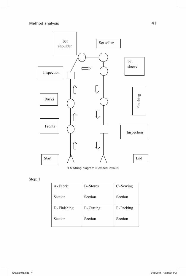
Method analysis 41
Start
Fronts
Backs
Set shoulder
Set collar
Set sleeve
Fini
shin
g
Inspection
Inspection
End
3.6 String diagram (Revised layout)
Step: 1
A-Fabric
Section
B-Stores
Section
C-Sewing
Section
D -Finishing
Section
E -Cutting
Section
F-Packing
Section
Chapter 03.indd 41 9/15/2011 12:31:31 PM
�� �� �� �� ��
42 Industrial engineering in apparel production
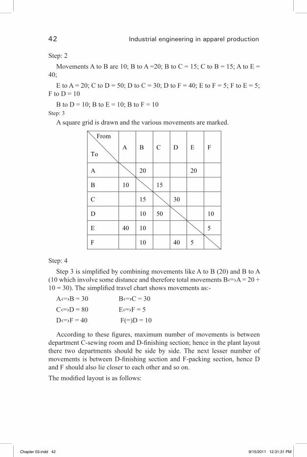
Step: 2Movements A to B are 10; B to A =20; B to C = 15; C to B = 15; A to E =
40;E to A = 20; C to D = 50; D to C = 30; D to F = 40; E to F = 5; F to E = 5;
F to D = 10B to D = 10; B to E = 10; B to F = 10
Step: 3A square grid is drawn and the various movements are marked.
From To
A B C D E F
A 20 20
B 10 15
C 15 30
D 10 50 10
E 40 10 5
F 10 40 5
Step: 4Step 3 is simplified by combining movements like A to B (20) and B to A
(10 which involve some distance and therefore total movements B‹=›A = 20 + 10 = 30). The simplified travel chart shows movements as:-
A‹=›B = 30 B‹=›C = 30 C‹=›D = 80 E‹=›F = 5D‹=›F = 40 F(=)D = 10
According to these figures, maximum number of movements is between department C-sewing room and D-finishing section; hence in the plant layout there two departments should be side by side. The next lesser number of movements is between D-finishing section and F-packing section, hence D and F should also lie closer to each other and so on.The modified layout is as follows:
Chapter 03.indd 42 9/15/2011 12:31:31 PM
�� �� �� �� ��
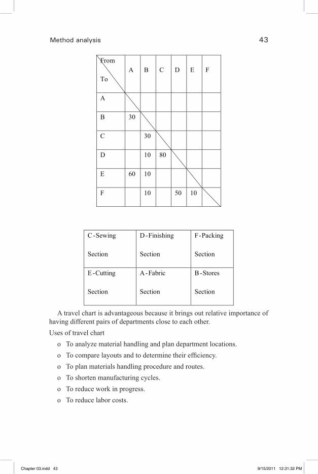
Method analysis 43
From
To A B C D E F
A
B 30
C 30
D 10 80
E 60 10
F 10 50 10
C-Sewing
Section
D -Finishing
Section
F-Packing
Section
E -Cutting
Section
A-Fabric
Section
B-Stores
Section
A travel chart is advantageous because it brings out relative importance of having different pairs of departments close to each other. Uses of travel chart
o To analyze material handling and plan department locations.o To compare layouts and to determine their efficiency.o To plan materials handling procedure and routes.o To shorten manufacturing cycles.o To reduce work in progress.o To reduce labor costs.
Chapter 03.indd 43 9/15/2011 12:31:32 PM
�� �� �� �� ��
44 Industrial engineering in apparel production
o To assist improving materials handling procedure.o To determine relative self-sufficiency of various areas.o To determine inventory control difficulties.o To make economical use of available areas.
3.8 Multiple activity chart (or) man–machine chart
This chart describes graphically the activity of a man and machine he is attending against a time scale. Where a number of workers work in a group or an individual operator handles two or more machine, their activities have to be coordinated for achieving proper results. A man–machine chart (multiple activity charts) records simultaneously the activities of all the workers and machines on a common time scale and thus shows inter relations between them. (Khanna, 2003).Purpose
(i) To detect idle times being enforced on machines and workers.(ii) To optimize work distribution between workers and machines.(iii) To detect number of workers in a group.(iv) Ultimately to develop an improved method of accomplishing a task
and to have an effective labor lost control.Construction
(a) A separate vertical bar or column is there to represent each subject (machines or operator).
(b) A common time scale is provided for all the subjects.(c) Activities of each subject in relation to those of the others are marked
in the respective columns.(d) Previously conducted time studies provide the time values for each
activity.(e) A brief description of each activity is marked on the chart.(f) Working and idle times are marked differently on the chart. For example, a worker is doing an operation on collar turning machine.
Suppose that the time to set up a machine is 0.50 minutes and machining time is 0.75 minutes.
Chapter 03.indd 44 9/15/2011 12:31:32 PM
�� �� �� �� ��
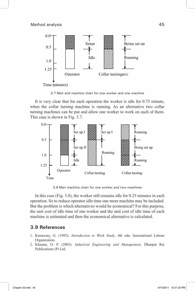
Method analysis 45
0.0
0.5
1.0
1.25
Set up
Running
Being set up
Idle
Time (minutes)
Operator Collar turning m/c
3.7 Men and machine chart for one worker and one machine
It is very clear that for each operation the worker is idle for 0.75 minute, when the collar turning machine is running. As an alternative two collar turning machines can be put and allow one worker to work on each of them. This case is shown in Fig. 3.7.
0.0
0.5
1.0
1.25
Set up I
Set up II
Idle
Set up I
Running
Running
Being set up
Running
Operator Collar turning
Collar turning
Time
3.8 Man machine chart for one worker and two machines
In this case (Fig. 3.8), the worker still remains idle for 0.25 minutes in each operation. So to reduce operator idle time one more machine may be included. But the problem is which alternatives would be economical? For this purpose, the unit cost of idle time of one worker and the unit cost of idle time of each machine is estimated and then the economical alternative is calculated.
3.9 References
1. Kanawaty, G. (1992). Introduction to Work Study, 4th edn, International Labour Organization.
2. Khanna, O. P. (2003). Industrial Engineering and Management, Dhanpat Rai Publications (P) Ltd.
Chapter 03.indd 45 9/15/2011 12:31:33 PM
�� �� �� �� ��
47
4Motion economy
4.1 Principles of motion economy
A motion is an act of moving body part. Fewer motions decrease the time and energy required to complete an operation (Glock and Kunz, 2009). The best method of performing a job is not only with minimum expenditure but certain other rules or principles should be observed for increasing the speed to achieve more economy in production. Although all the principles are not applied to every operation, but they form basis or a code for improving the efficiency and reducing fatigue in manual work.
(a) Principles related to the use of the “human body”.(b) Principles related to the “arrangement of the work place”.(c) Principles related to the “design of tools and equipment”. (d) Rules concerning “time conservation”.
4.1.1 Principles related to the use of the “human body”
1. Both hands should start as well as complete their motions at the same time.
2. Both hands should not be idle at the same time except during rest periods.
3. Use both hands simultaneously and use best motion sequence.4. Hand motions should be confined to the lowest possible classification
in order to reduce fatigue. These are listed in the order of giving least fatigue and maximum economy (Khanna, 2003).
First – Finger motionSecond – Finger and wrist motionsThird – Finger, wrist and lower arm motions Fourth – Finger, wrist, lower arm and upper arm motions
Chapter 04.indd 47 9/15/2011 12:31:51 PM
�� �� �� �� ��

48 Industrial engineering in apparel production
Fifth – Finger, wrist, lower arm, upper arm and body motions 5. Utilize momentum to assist the worker, wherever possible.6. Smooth continuous motions produce less fatigue in comparison to
zigzag or straight line motions involving sudden and sharp change in direction.
7. Ballistic movements are faster, easier and more accurate than controlled movements.
8. Sequence of motions should be arranged to build rhythm and automatically into the operation.
9. Hands should be relieved of all work that can be done by feet or other parts of the body.
4.1.2 Principles related to the arrangement of the work place
1. All tools and materials should be placed at a definite and fixed place with easy reach.
2. All tools materials and actuating devices should be placed in front of the operator at a distance as near as possible.
3. Provide gravity feed bins and use power or gravity conveyors to transport materials.
4. Wherever possible use drop deliveries. Drop delivery means dropping the article into a chute or on a conveyor as near to the point of assembly as possible so that gravity assists rather than the hands to reach the part to its required place.
5. Tools and materials should be located in such a way to achieve the best sequence of motions.
6. Illuminate the work places properly for adequate seeing and visual perception.
7. Provide proper working tables, stools and chairs, etc., because to work in standing or sitting position on floor consumers more time and energy.
8. The height of the work place and chair, etc., should be such that worker can either sit or stand comfortably.
9. Chairs provided should make good posture possible.10. Keep the shops in good order, neat and clean (Khanna, 2003).
Chapter 04.indd 48 9/15/2011 12:31:51 PM
�� �� �� �� ��
Motion economy 49
4.1.3 Principles related to the design of tools and equipment
1. The hands should not be used for work that can be done more advantageously with the help of devices. Therefore, following devices should be used to reduce manual work and to free both the hands as far as possible:
(a) Use power operated tools and equipments, (b) Use vices, jigs and fixtures, etc., (c) Use stops, guides, etc., (d) Use foot pedals.2. Reduced noise increases the speed or work and requires less energy.3. Wherever practicable, tools and materials should be propositioned to
reduce search, find and the select operations.4. Wherever possible two or more tools should be combined.5. Handles on tools and cranks should be designed to permit maximum
contact with the hands, particularly where force is applied, such as in a screw driver, pliers, scrappers, etc.
6. When each finger performs some specific movement, such as in type writing, the load should be distributed in accordance with the inherent capacities of the fingers.
7. The location of levers, cross bars and hand wheels, etc, should be so decided that the operation can operate with the least change in body position and with greatest mechanical advantage.
4.1.4 Rules concerning “time conservation”
1. Even temporary ceasing of work by a man or machine should not be encouraged.
2. Machine should not run idle.3. Two or more jobs should be worked upon at the same time or two or
more operations should be carried out on a job simultaneously. Number of motions involved in completing a job should be minimized.
4.1.5 Classification of movements
The classification is built up on the pivots around which the body parts must move as shown in the Table 4.1 below.
Chapter 04.indd 49 9/15/2011 12:31:51 PM
�� �� �� �� ��

50 Industrial engineering in apparel production
Table 4.1 Classification of movements
Class Pivot Body part(s) move1 Knuckle Finger 2 Wrist Finger and wrist 3 Elbow Finger, wrist and lower arm 4 Shoulder Finger, wrist, lower arm and upper arm 5 Trunk Finger, wrist, lower arm, upper arm and body
It is obvious that each movement above class 1 will involve movements of all classes below it. Thus saving in effort resulting from using the lowest class possible is obvious. If, in laying out the work place, everything needed is placed within easy reach, this will minimize the class of movement which the work itself requires from the operators.
4.2 Two-handed process chart (Left hand and right hand chart)
The two-handed process chart is a process chart in which the activities of a worker’s hands
(or limbs) are recorded in their relationship to one another.This chart is used to improve the motion sequence of an operator. This
chart is used to minimize the necessary motions and to arrange the remaining motions in an economical way. This chart is prepared after studying the work place, arrangement of the work and of the equipment while he is working (Seminar SCT, 2010).
The two-handed process chart is a specialized form of process chart because it shows the two hands (and sometimes the feet) of the operator moving or static in relation to one another, usually in relation to a time scale. One advantage of incorporating a time scale in the chart form is that the symbols for what the two hands are doing at any given moment are brought opposite each other.
The two-handed process chart is generally used for repetitive operations; it is recorded when one completes cycle of the work. Recording is carried out in more detail than is normal or flow process chart. A single operation on a flow process chart may be broken down into a number of elemental activities which together make up the operation. The two-handed process chart generally employs the same symbols as the other process charts; however, because of the greater detail covered, the symbols are accorded slightly different meanings: Operation – It is used for the activities of grasp, position, use, release of a
tool, component or material. Transport – It is used to represent the movement of the hand (or limb) to or from the work, a tool or material.
Chapter 04.indd 50 9/15/2011 12:31:51 PM
�� �� �� �� ��

Motion economy 51
Delay – It is used to denote time during the hand or limb being charted is idle (although the other may be in use).
Hold – It is used to present the activity of holding the work, a tool or material – that is, when the hand being charted is holding something. Some of the operations like assembling of small instruments such as
pressure gauge, carburetor, time piece and fuel pump, etc., where both hands are used for placing the different components of the article, left hand and right hand charts are prepared. The study of the chart gives the clear picture of defective arrangement of tools, incorrect motion sequence and unnecessary and defective motions, etc.
Figure 4.1 explains a two-handed chart for pocket attaching operation. Fronts are picked from centre table (right) and pocket from left extension table – sew-dispose on bar. The movements of right, left and both hands are recorded systematically. The various activities of the hands are listed as below.
Department: Shirts Section: A Time/Date: 11.00am/12.10.2010
Operation: Pocket Attaching Operator: Nirmala Observer: RajaMethod Summary Fronts are picked from centre table (Right) and pocket from
Left extension table – Sew-Dispose on Bar,
Machine: Juki SNLS ¼’’ Left Compensation presser foot Centre table Needle Pocket Disposal bar Operator
Left Hand Symbol LH
Symbol RH
Right Hand
Pick up front from thecentretable
Present @ the needle and align
Present @ the needle and align
Pick up pocket from the small extension table
Align and Match the check on Front @ needle
Align and Match the check on Front @ needle
Sew all three sides Sew all three sides
Dispose on the dispose bar
4.1 Two-handed process chart
Chapter 04.indd 51 9/15/2011 12:31:52 PM
�� �� �� �� ��

52 Industrial engineering in apparel production
Summary
Symbols LH RH
3 3
0 0
2 1
0 0
4.3 Micro motion study
Some motions require very small time and it is difficult to measure time for these motions accurately. But the time required by these motions cannot be neglected because they are repeated hundreds of time. Therefore, the motions are taken on picture films with the help of picture camera. Very small time up to 0.0005 minutes can be measured by this system. When picture camera is used, the procedure is known as “micro motion study” (Kanawaty, 1992).
The method gives very accurate analysis of the product, but being a costly one it is used when products are likely to continue for a long time. Micro motion study has the following important advantages:
(a) It provides permanent record of motion study with the help of film.(b) A large number of workers can see the procedure at any time even after
the completion of motion study.(c) Differences in the old and new methods can be demonstrated, if both
are filmed.(d) Films can be demonstrated at any desired speed.(e) It gives very accurate time for each motion or operation than that noted
by the stop watch.
4.3.1 Therbligs
Frank Gilbreth developed a set of 17 elementary motions commonly found in manual operations and called them “Therbligs”, reverse spelling of his name. We know that motion study is used for deciding the best way of doing work for which present and proposed methods are observed by experts by recording on charts. For the purpose of recording the motions, he splitted up different motions of process into 17 fundamental elements made by various members
Chapter 04.indd 52 9/15/2011 12:31:52 PM
�� �� �� �� ��
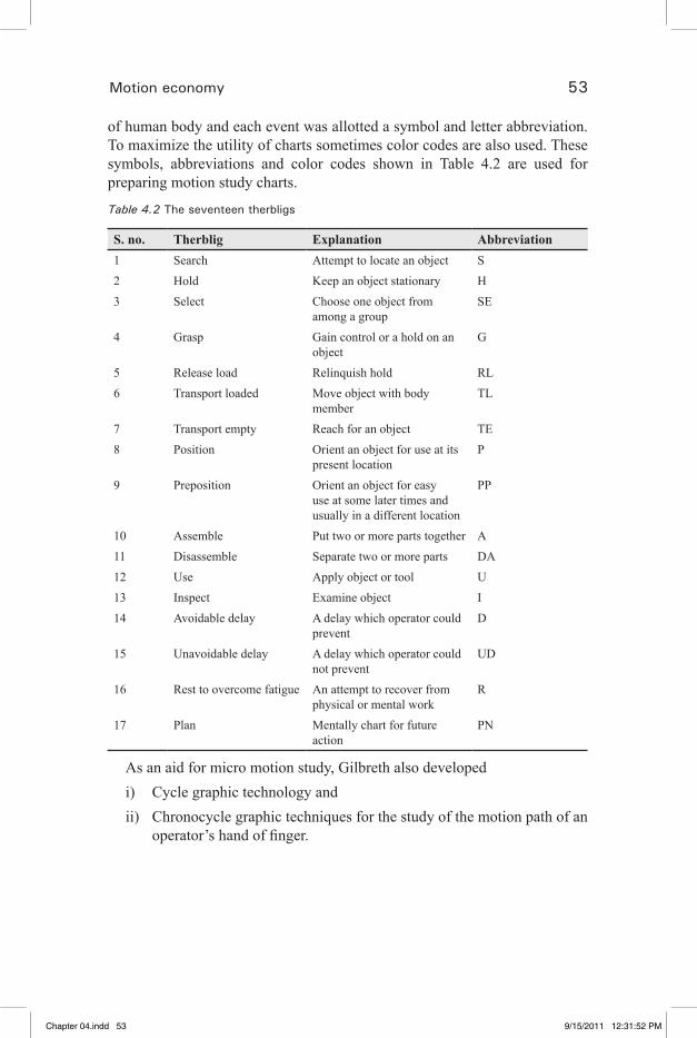
Motion economy 53
of human body and each event was allotted a symbol and letter abbreviation. To maximize the utility of charts sometimes color codes are also used. These symbols, abbreviations and color codes shown in Table 4.2 are used for preparing motion study charts.
Table 4.2 The seventeen therbligs
S. no. Therblig Explanation Abbreviation1 Search Attempt to locate an object S2 Hold Keep an object stationary H3 Select Choose one object from
among a groupSE
4 Grasp Gain control or a hold on an object
G
5 Release load Relinquish hold RL6 Transport loaded Move object with body
memberTL
7 Transport empty Reach for an object TE8 Position Orient an object for use at its
present locationP
9 Preposition Orient an object for easy use at some later times and usually in a different location
PP
10 Assemble Put two or more parts together A11 Disassemble Separate two or more parts DA12 Use Apply object or tool U13 Inspect Examine object I14 Avoidable delay A delay which operator could
preventD
15 Unavoidable delay A delay which operator could not prevent
UD
16 Rest to overcome fatigue An attempt to recover from physical or mental work
R
17 Plan Mentally chart for future action
PN
As an aid for micro motion study, Gilbreth also developedi) Cycle graphic technology andii) Chronocycle graphic techniques for the study of the motion path of an
operator’s hand of finger.
Chapter 04.indd 53 9/15/2011 12:31:52 PM
�� �� �� �� ��
54 Industrial engineering in apparel production
4.3.2 Cycle graph
This method was developed by Frank. B. Gilbreth to study the motion path of an operator. These are very accurate methods and use a high speed camera for photographing the path of motion, little light bulbs attached to the hands or fingers of the operator trace continuous lines of movements on the photographic plate exposed to the view, when the operator is doing the job. Cycle graph does not give any clues regarding speed and direction of movement.
4.3.3 Chronocycle graph
If an interrupter is placed in the electric circuit (on and off relay flicker circuit) with the bulb and the light is flashed quickly and off slowly at a frequency of 10–30 times per second, then the path of bulb in the photograph will appear as a dotted line with pear-shaped dots indicating the direction of motion. More elongated spots with longer gaps between them imply higher working speed. The space between the dots will be according to the speed of the hand or finger of the body. Size and shape of the pear-shaped dot will show whether body part is in acceleration or in retardation. The number of dots will give the time taken by that motion and the technique is called a chronocycle graph.The technique of chronocycle graph is useful in the following situations:
1. Analyzing a complex single purpose movement. 2. Recording of unrestricted movements.3. Developing new method.4. Training of operators in operations requiring skill.5. Differentiating between good and clumsy movements. 6. Short cycle operations.7. Sharping the movements of hands.
4.3.4 SIMO (Simultaneous Motion) chart
This is similar to “two-hand chart” with the difference that the time required for each motion is drawn to scale with the vertical axis and sometimes colored to represent the particular motion (Seminar SCT, 2010).The procedure to construct this chart is as under:
A camera with high speed clock is placed near the work place and is used to record time and the operator’s actions simultaneously. After recording, the film is processed and viewed to determine the motions performed and time taken. From these records, activities and time taken are plotted in the form of SIMO chart shown in Table. 4.3.
Chapter 04.indd 54 9/15/2011 12:31:52 PM
�� �� �� �� ��
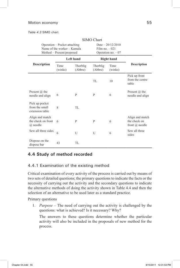
Motion economy 55
Table 4.3 SIMO chart
SIMO Chart Operation – Pocket attaching Date – 20/12/2010 Name of the worker – Kamala Film no. – 021 Method – Present/proposed Operation no. – 07
DescriptionLeft hand Right hand
DescriptionTime(winks)
Therblig(Abbre)
Therblig(Abbre)
Time(winks)
TL 10Pick up front from the centre table
Present @ the needle and align 6 P P 6
Present @ the needle and align
Pick up pocket from the small extension table
8 TL
Align and match the check on front @ needle
6 P P 6Align and match the check on front @ needle
Sew all three sides6 U U 6
Sew all three sides
Dispose on the dispose bar 43 TL
4.4 Study of method recorded
4.4.1 Examination of the existing method
Critical examination of every activity of the process is carried out by means of two sets of detailed questions; the primary questions to indicate the facts or the necessity of carrying out the activity and the secondary questions to indicate the alternative methods of doing the activity shown in Table 4.4 and then the selection of an alternative to be used later as a standard practice. Primary questions
1. Purpose – The need of carrying out the activity is challenged by the questions: what is achieved? Is it necessary? Why?
The answers to these questions determine whether the particular activity will also be included in the proposals of new method for the process.
Chapter 04.indd 55 9/15/2011 12:31:53 PM
�� �� �� �� ��
56 Industrial engineering in apparel production
2. Means – The means of carrying out the activity are challenged by the questions: how is it done? and why that way?
3. Place – The location of carrying out the activity is challenged by the questions: where is it done? and why there?
4. Sequence – The time of carrying out the activity is challenged by the questions: when is it done? and why then?
5. Person – The level of skill and experience of the person performing the activity is challenged by the questions: who does it? and why that person?
The main objective of the primary questions is to make sure that the reasons for every aspect of the presently used method are clearly understood. The answers to these questions should clearly bring out any part of the work which is unnecessary or inefficient in respect of means, sequence, person, or place.
Secondary questionsThe aim of secondary questions is to arrive at suitable alternatives to the
presently used method.1. Purpose – If the answer to the primary question “Is the activity
necessary?” is convincingly ‘Yes’, then alternatives to achieve the object of carrying out the activity are considered by the question: what else could be done?
2. Means – All the alternative means to achieve the objectives are considered by the question: how else could it be done?
3. Place – Other places for carrying out the activity are considered by the question: where else could it be done?
4. Sequence – The secondary question asked under this heading is – when else could it be done?
5. Person – The possibilities for carrying out the activity by other persons are considered by asking the question: who else should do it?
This phase involves the search of alternative possibilities within the imposed restrictions of cost, volume of production and the like. For this method study, man uses his own past experience with same or similar problems or refers to text books, handbooks, etc.
The answers to the following questions are then sought through evaluation of the alternatives.
‘How should it be done?’‘What should be done?’‘Where should it be done?’
Chapter 04.indd 56 9/15/2011 12:31:53 PM
�� �� �� �� ��
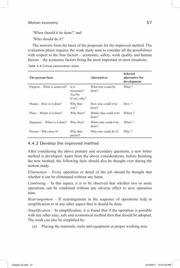
Motion economy 57
‘When should it be done?’ and‘Who should do it?’The answers form the basis of the proposals for the improved method. The
evaluation phase requires the work study man to consider all the possibilities with respect to the four factors – economic, safety, work quality and human factors – the economic factors being the most important in most situations.Table 4.4 Critical examination sheet
The present facts AlternativesSelected alternative for development
Purpose – What is achieved? Is it necessary? Yes/NoIf yes, why?
What else could be done?
What ?
Means – How is it done? Why that way?
How else could it be done?
How ?
Place – Where is it done? Why there? Where else could it be done?
Where ?
Sequence – When is it done? Why then? When else could it be done?
When ?
Person – Who does it? Why that person?
Who else could do it? Who ?
4.4.2 Develop the improved method
After considering the above primary and secondary questions, a new better method is developed. Apart from the above considerations, before finishing the new method, the following facts should also be thought over during the motion study.Elimination – Every operation or detail of the job should be thought that whether it can be eliminated without any harm.Combining – In this aspect, it is to be observed that whether two or more operations can be combined without any adverse effect to save operation time.Rearrangement – If rearrangement in the sequence of operations help in simplification or in any other aspect then it should be done. Simplification – In simplification, it is found that if the operation is possible with any other easy, safe and economical method then that should be adopted. The work can also be simplified by:
(a) Placing the materials, tools and equipment at proper working area.
Chapter 04.indd 57 9/15/2011 12:31:53 PM
�� �� �� �� ��

58 Industrial engineering in apparel production
(b) Using gravity feed hoppers and other material handling equipment.(c) Taking useful work by both hands.(d) Using special jigs and fixtures.
4.4.3 Defining the improved method
Once a decision has been taken on the changes in method to be adopted, it is important that the new method should be strictly defined.
For all jobs it is desirable to prepare a written standard practice also known as a “method documentation sheet”. The same is shown in Table 4.5. This serves several purposes as mentioned below:
1. It records the improved method for future reference.2. It can be used to explain the new method to management, supervisors
and operators. 3. It is an aid to training or retraining operators and can be used by them
for reference until they are fully conversant with the new method.4. It forms the basis on which time studies may be taken for setting
standards.
4.4.4 Installing the improved method
After having developed the method, it is required to install. The new method must first be got approved from the supervisors, workers and management. Then the workers must be trained to work according to this new method and their habits must be developed to follow the correct way. For some times, close contacts must be maintained with progress of the job until it runs satisfactorily. It is at this point that active support is required from management and trade unions alike. Installation can be divided into five stages, namely:
1. Gaining acceptance of the change by management.2. Gaining acceptance of the change by the departmental supervision.3. Gaining acceptance of the change by the workers and their
representatives.4. Preparing to make the changes.5. Controlling the change-over.
Teaching a new methodThere are five essential steps in the teaching of a new method:1. The mind of the operator must be focused upon what is to be learned.2. The method must be demonstrated and explained.
Chapter 04.indd 58 9/15/2011 12:31:53 PM
�� �� �� �� ��

Motion economy 59
3. The operator must be allowed to practice.4. Constant correction of fault.5. Operator must persevere.
Training and re-training of operativesIn the training or re-training of operatives, the important thing is to develop
the habit of doing the job in the correct way.
4.4.5 Maintaining the new method
Once a method is installed, it should be maintained in its specified form, and is not allowed to slip back to old form or introduction of any other unauthorized changes. For proper maintenance, following steps are advised:
1. Copies of the job instruction sheets (Table 4.4) should be distributed to all concern.
These sheets must supply the detail for setting up the job and proper operation.
2. Routine checks are necessary to compare what is actually being done against the job instruction sheets.
3. Selection and training of persons must be done according to the job specification for this new method.
Table 4.5 Method documentation sheet
Method documentation Operation – Attach pocket to left front (5 sides) Type of machine – Single needle lock stitchS. No. Motion description Frequency Action1 Pick up the left front
Pick up
2 Spread the panel3 Check the mark for
matching pocket4 Match the pocket to
left front5 Match the parts to
Foot6 Backtack at the
beginning and start Process
7 Sew 2 cm8 Turn the panel9 Knee lift pedal
(Continued)
Chapter 04.indd 59 9/15/2011 12:31:53 PM
�� �� �� �� ��
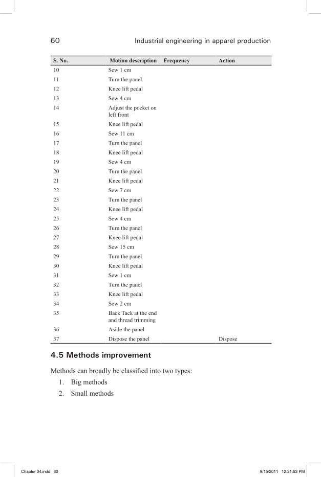
60 Industrial engineering in apparel production
S. No. Motion description Frequency Action10 Sew 1 cm11 Turn the panel12 Knee lift pedal13 Sew 4 cm14 Adjust the pocket on
left front15 Knee lift pedal16 Sew 11 cm17 Turn the panel18 Knee lift pedal19 Sew 4 cm20 Turn the panel21 Knee lift pedal22 Sew 7 cm23 Turn the panel24 Knee lift pedal25 Sew 4 cm26 Turn the panel27 Knee lift pedal28 Sew 15 cm29 Turn the panel30 Knee lift pedal31 Sew 1 cm32 Turn the panel33 Knee lift pedal34 Sew 2 cm35 Back Tack at the end
and thread trimming36 Aside the panel37 Dispose the panel Dispose
4.5 Methods improvement
Methods can broadly be classified into two types:1. Big methods2. Small methods
Chapter 04.indd 60 9/15/2011 12:31:53 PM
�� �� �� �� ��
Motion economy 61
4.5.1 Big methods
This type of method improvement is normally associated with the engineering function.
Machines • (Pocket setters, profile setting, automatic hemmers, and label sewers)
Attachments• (Loading devices, stacking devices, folders, thread cutters)
Work aids• (Bins that carry work away from the machines, trays for positioning of
work) Machine adjustments (Needle positioner)• Construction changes in garment and clubbing of operations.•
4.5.2 Small methods
The way the operator handles the work.• The way she controls the machine.• The way the operator disposes the machine etc.,•
This can be considered as everyone’s responsibility. But it is especially the responsibility of the executive (Seminar SCT, 2010).Small methods can be grouped into three, as below:
(A) Basics(B) Principles of motion economy(C) Specifics of sewing jobs
BasicsCorrect table height• Correct chair height• Operators posture at the machine• Both feet on treadle•
Principles of motion economy Motions should be simultaneous.• Motions should be symmetrical.•
Chapter 04.indd 61 9/15/2011 12:31:53 PM
�� �� �� �� ��

62 Industrial engineering in apparel production
Motions should be natural.• Motions should be rhythmical.• Motions should be habitual.•
Specifics of sewing jobsTypes of operator motions/movements to be discouraged.• (a) Operator being idle during machine time.(b) Operator unconsciously pit-pats the garment after sewing.(c) Operator unconsciously inspects each garment after sewing.(d) Operator stops while sewing more than absolutely essential.(e) Operator rides knee lift pedal.(f) Operator picks up, disposes, and picks up again.(g) Operator re-grasps or shifts from hand to hand.(h) Operator straightens out the material that is not sewn.Types of operator motions/movements to be encouraged• (a) Operator locates parts as close as possible to needle.(b) Operator folds anything that needs folding while moving to
machine.(c) Operator uses simultaneous motions.
4.6 References
1. Kanawaty, G. (1992). Introduction to Work Study, 4th edn, International Labour Organization.
2. Khanna, O. P. (2003). Industrial Engineering and Management, Dhanpat Rai Publications (P) Ltd.
3. Glock, R. E. and Kunz, G. I. (2009). Apparel manufacturing analysis, Sewn Product Analysis, 4th edn, Pearson.
4. Seminar SCT (2010). Technical Workplace Skills for the Garment Industry, Sona School of Garment and Fashion Technology.
Chapter 04.indd 62 9/15/2011 12:31:53 PM
�� �� �� �� ��
63
5Apparel production systems and factory layout
5.1 Introduction
There are many types of activities in which workers move at irregular intervals between a number of points in the working area, with or without material. This situation occurs very often in industry and commerce and even in the home (Glock and Kunz, 2009). In manufacturing concerns it occurs when:
Bulk material is being fed to or removed from continuous process and is •stored around the process;An operator is looking after two or more machines;•Laborers are delivering materials to or removing work from a series of •machines or work places.
5.2 Garment production systems
An apparel production system is an integration of materials handling, production processes, personnel, and equipments that direct workflow andgenerate finished products. The various apparel production systems arediscussed in this chapter.
5.2.1 Individual system/make through/whole garment system
In this system the entire garment operation process is done by an individual. From cutting to packing the individual person performs the entire job. With this production system the operator would be given a bundle of cut work and would proceed to sew it according to his or her own method of work. Of necessity, the labour required by this system must be highly skilled and versatile, a combination which is becoming exceedingly rare and increasingly expensive. This type of system is effective when a very large variety of garments have to be produced in extremely small quantities. A typical application would be in the sewing room of a boutique, which produces its own merchandise.
Chapter 05.indd 63 9/15/2011 12:32:07 PM
�� �� �� �� ��

64 Industrial engineering in apparel production
5.2.2 Whole garment production system
There are two types of whole garment production systems: (1) complete whole garment and (2) departmental whole garment. In the whole garment system an individual makes the entire garment from cutting the cloth to sewing and pressing the garment. The garment is ready for dispatch once the operator completes the final operation. This type of system is used in few places,which are engaged in custom-whole sale; they are normally high priced and exclusively made for a particular customer. They are limited in number and distribution; normally about 10–20 garments are made.
The departmental whole garment system is also used by custom wholesale manufacturers as well as high price or better dress manufacturers. In the departmental whole garment system one individual does all the work with the equipment allocated to a department. For example on person does all the cutting work in cutting department, second person does all the sewing work in sewing department, third person does the pressing and packing work. The workers in this system may use more than one equipment to complete his/her job.Advantages
1. This system is more effective when a very large variety of garments have to be produced in extremely small quantities.
2. In individual piece rate system the operators will do with full involvement.Tofinishmorepieces,toearnmoremoney.
3. Operator will be specialized in his own working area.4. As the pay depends upon the complication of the operation, the operator
triestofinishthecomplicatedoperationwithoutanydifficulties.5. The work in progress (WIP) is reduced, at a time one cut garment to
one operator and so the amount as inventory is reduced.Disadvantages
1. Highly skilled labours are used, so the cost of labour is high.2. Theoperatorismoreconcernedonthenumberofpiecesfinishedrather
than the quality of work.3. Productivity is less due to lack of specialization.4. For long run/bulk quantity of same style is not effective in this
system.
5.3 Group system
This is a development of the individual system, with the difference that the operators specialize in one major component and sew it from beginning to
Chapter 05.indd 64 9/15/2011 12:32:07 PM
�� �� �� �� ��
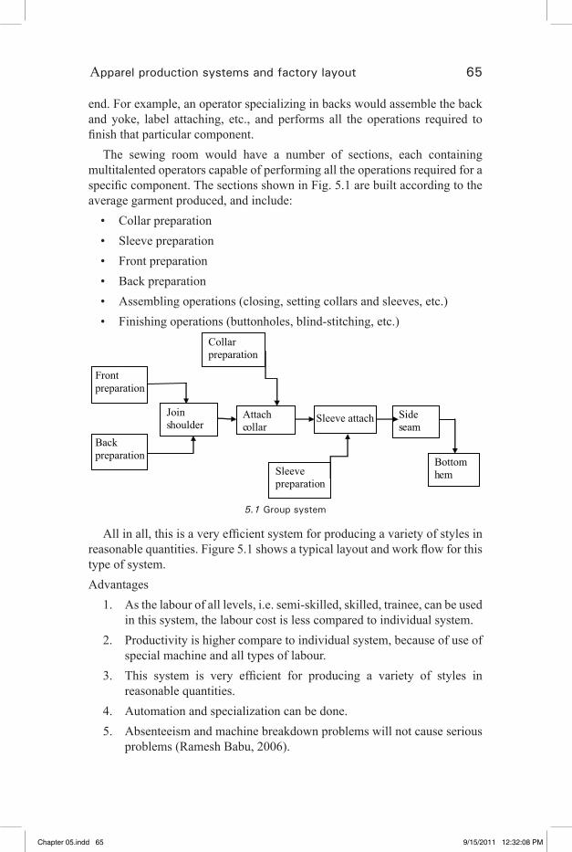
Apparel production systems and factory layout 65
end. For example, an operator specializing in backs would assemble the back and yoke, label attaching, etc., and performs all the operations required to finishthatparticularcomponent.
The sewing room would have a number of sections, each containing multitalented operators capable of performing all the operations required for a specificcomponent.ThesectionsshowninFig.5.1arebuiltaccordingtotheaverage garment produced, and include:
Collar preparation•Sleeve preparation•Front preparation•Back preparation•Assembling operations (closing, setting collars and sleeves, etc.)•Finishing operations (buttonholes, blind-stitching, etc.)•
Collar preparation
Front preparation
Back preparation
Join shoulder
Attach collar
Sleeve attach
Sleeve preparation
Side seam
Bottom hem
5.1 Group system
Allinall,thisisaveryefficientsystemforproducingavarietyofstylesinreasonablequantities.Figure5.1showsatypicallayoutandworkflowforthistype of system.Advantages
1. As the labour of all levels, i.e. semi-skilled, skilled, trainee, can be used in this system, the labour cost is less compared to individual system.
2. Productivity is higher compare to individual system, because of use of special machine and all types of labour.
3. This system is very efficient for producing a variety of styles inreasonable quantities.
4. Automation and specialization can be done.5. Absenteeism and machine breakdown problems will not cause serious
problems (Ramesh Babu, 2006).
Chapter 05.indd 65 9/15/2011 12:32:08 PM
�� �� �� �� ��

66 Industrial engineering in apparel production
Disadvantages1. All the operators are involved in the work to maintain the quality of
garment.2. Even though productivity is high still the highly skilled operators
required to perform simple operation within the section.3. Group of people are involved in each section, so we require more WIP
which increases the inventory cost.4. As this is not a bundling system, there are more chances of shade and
size variation; hence quality and production are affected.
5.4 Progressive bundle synchro straight line system – batch system
Asthenamesuggests,thissystemisbasedonasynchronizedflowofworkthrough each stage of producing a garment (Fig. 5.2). Time-synchronization isthemostimportantfactorofthissystembecausetheflowofworkcannotbesynchronized if there are considerable variations in the standard times allowed for all the operations performed on the line. For example, if one operation has a value of 1.5 minutes then all the other operations in the line must have the same, or a very close, value. The manipulation required to balance the standard time for each operator can sometimes lead to illogical combinations of whole or part operations which are not always conducive to the overall efficiencyofindividualoperators.
The synchro system by its very nature is rigid and particularly vulnerable to absenteeism and machine breakdowns. At all times reserve operators and machinesmustbeavailabletofillthegaps.Inaddition,thissystemrequiresasufficientvolumeofthesametypeofgarmenttokeepthelineincontinuousoperation.To be effective, this system requires
Volume production•Accurate line balancing•Skilled supervision•Reserve operators•Reserve machinery and equipment•
Chapter 05.indd 66 9/15/2011 12:32:08 PM
�� �� �� �� ��
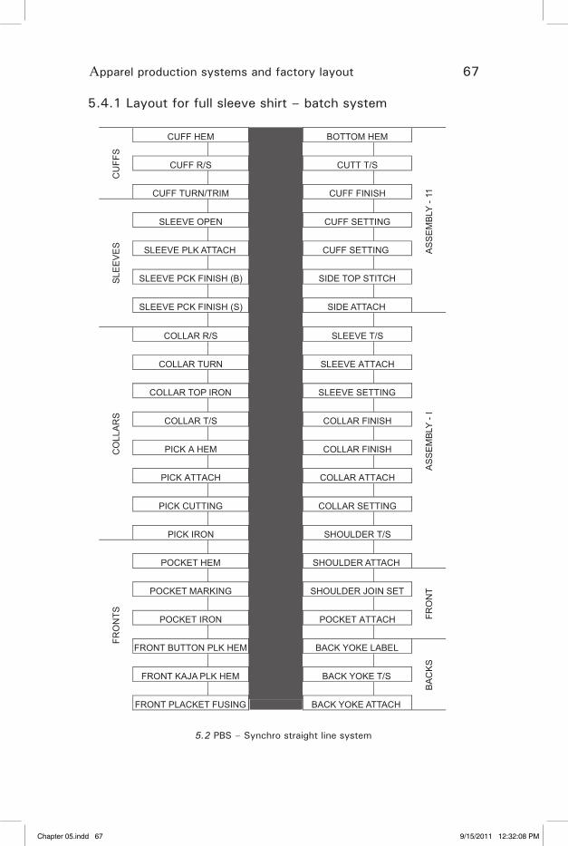
Apparel production systems and factory layout 67
5.4.1 Layout for full sleeve shirt – batch systemC
UFF
S
CUFF HEM BOTTOM HEM
AS
SE
MBL
Y - 1
1
S/T TTUC S/R FFUC
HSINIF FFUC MIRT/NRUT FFUC
SLE
EV
ES
GNITTES FFUC NEPO EVEELS
SLEEVE PLK ATTACH CUFF SETTING
SLEEVE PCK FINISH (B) SIDE TOP STITCH
SLEEVE PCK FINISH (S) SIDE ATTACH
AS
SE
MBL
Y - I
CO
LLA
RS
S/T EVEELS S/R RALLOC
HCATTA EVEELS NRUT RALLOC
COLLAR TOP IRON SLEEVE SETTING
HSINIF RALLOC S/T RALLOC
HSINIF RALLOC MEH A KCIP
HCATTA RALLOC HCATTA KCIP
GNITTES RALLOC GNITTUC KCIP
S/T REDLUOHS NORI KCIP
FRO
NTS
POCKET HEM SHOULDER ATTACH
FRO
NT POCKET MARKING SHOULDER JOIN SET
HCATTA TEKCOP NORI TEKCOP
FRONT BUTTON PLK HEM BACK YOKE LABEL
BAC
KS
FRONT KAJA PLK HEM BACK YOKE T/S
FRONT PLACKET FUSING BACK YOKE ATTACH
5.2 PBS – Synchro straight line system
Chapter 05.indd 67 9/15/2011 12:32:08 PM
�� �� �� �� ��

68 Industrial engineering in apparel production
Given that these conditions are fulfilled, the synchro system can be veryefficient.Advantages
1. Labours of all levels, i.e., unskilled, skilled, semi-skilled labours, are involved in this system where the operations are broken into small simple operation. Hence the cost of labour is very cheap.
2. Here the quantity of each component is checked during the individual operation itself, so the quality is good.
3. The components are moved in bundles from one operation to next operation, so there is less chance for confusion like, lot mix-up, shade variation, size variation, etc.
4. Specialization and rhythm of operation increases productivity.5. As the WIP is high in this system, it is a stable system. Because of the
buffer, the breakdown, absenteeism, balancing of line, change of style can be easily managed.
6. An effective production control system and quality control system can be implemented.
(a) Time study, method study techniques; (b) Operator training programme; (c) Use of material handling equipments, such as centre table, chute, conveyor, trolley, bins, etc.
7. Bundle tracking is possible, so identifying and solving the problems becomes easy (Ramesh Babu, 2006).
Disadvantages1. Balancingthelineisdifficultandthisproblemissolvedbyeffective
supervisor.2. Proper maintenance of equipment and machinery is needed.3. Proper planning is required for each batch and for each style, which
takes lot of time.4. Improper planning causes labour turnover, poor quality, less production,
etc.5. Increase in WIP in each section increases the inventory cost.6. Planned and proper layout should be made to make the system effective,
i.e.smoothflowofmaterial.7. Variety of styles, less quantity is not effective in this system.8. Shuttle operators and utility operators are needed in every batch to
balance the line effectively.
Chapter 05.indd 68 9/15/2011 12:32:08 PM
�� �� �� �� ��

Apparel production systems and factory layout 69
5.5 Unit production system (UPS)
As a mechanical system this has been in use for many years, but a major advancewasmadein1983whencomputerswerefirstusedtoplan,controlanddirecttheflowofworkthroughthesystem.
The essential feature of this type of system is as follows:1. The unit of production is a single garment and not in bundles.2. The garment components are automatically transported from work
station to work station according to a pre-determined sequence.3. The work stations are so constructed that the components are presented
as close as possible to the operator’s left hand in order to reduce the amount of movement required to grasp and position and component to be sewn.
The operational principles are as follows:All the components for one garment are loaded into a carrier at a work
station especially designed for this purpose. The carrier itself is divided into sections, with each section having a quick-release clamp which prevents the components from falling out during movement through the system. When a batch of garments has been loaded into carriers it is fed past a mechanical or electronic device which records the number of the carrier and addresses it to itsfirstdestination.Someofthemoreintelligentsystemsaddressthecarrierswith all the destinations they have to pass through to completion (Fig. 5.3).
5.3 Unit production system
Chapter 05.indd 69 9/15/2011 12:32:09 PM
�� �� �� �� ��

70 Industrial engineering in apparel production
The loaded carriers are then fed on to the main powered line, which continually circulates between the rows of machines. This main, or head, line is connected to each work station by junctions that get opened automatically if the work on a carrier is addressed to that particular station. The carrier is directed to the left side of the operator and waits its turn along with the other carriers in the station (Fig. 5.3).
When the operator has completed work on one carrier, a push button at the side of the sewing machine is pressed and this actuates a mechanism, which transports the carrier back to the main line. As one carrier leaves the station, another is automatically fed in to take its place. When the carrier leaves the station, it is recorded on the data collection system, and then is addressed to its next destination.
The marked advantages of this type of system are as follows:Bundle handling on the part of the operator is completely eliminated.•The time involved in the pick-up of work and its disposal is reduced to •the minimum possible.Output is automatically recorded, thus eliminating the necessity for the •operator to register work.The computerized systems automatically balance the work between •stations performing the same operation.Up to 40 styles can be produced simultaneously on one system.•
Unit production system requires substantial investments, which are not always justified by conventional pay-back calculations. Apart from themeasurable tangiblebenefits,UPSalsohavemany intangiblebenefits suchasamoreorderlyandcontrolledflowofwork,andtheabilityviathecontrolcomputer of simulating the production situation some times in advance. These intangiblesaredifficulttomeasure,buttheymakeaverypositivecontributionto the overall viability of the unit.
All things considered, unit production systems have major advantages over the other entire manual and the mechanical systems used for the mass production of clothing. Most importantly, they provide a clothing factory with the capability to respond quickly to any changes, which might occur. In the fast moving fashion business, this is essential.Advantages
1. Bundle handling is completely eliminated.2. The time involved in the pickup and disposal is reduced to minimum.3. Output is automatically recorded, hence eliminates the operator to
register the work.
Chapter 05.indd 70 9/15/2011 12:32:09 PM
�� �� �� �� ��

Apparel production systems and factory layout 71
4. The computerized systems automatically balance the work between stations.
5. Up to 40 styles can be produced simultaneously on one system.Disadvantages
1. Unit production system requires high investments.2. The payback period of the investment takes long time.3. Proper planning requires being effective.
5.6 Quick response sewing systemThissystemwasfirstdevelopedinJapantoenablequickresponsestobemadeto market changes, especially when orders for individual styles were in small lots. Each work station is equipped with two or four machines and the operator takes the garment through the required operations, including pressing, before it is transported to the next work station.
5.4 Quick response sewing system
Some of the basic machinery is duplicated in different stations, and if there is a bottle-neck in one section the over-load is automatically transported to other stations where operator capacity is available.
All the parts of one garment are loaded onto a hanging clamp attached to the trolley and in theory, there should only be one garment at each work station. Work is transported by a computer-controlled overhead trolley system, and each station has an individual controller which provides the operator with information on the style being worked on. This information comes from an information card which accompanies each trolley.
A less sophisticated version of QRS uses a wheeled trolley which contains thecomponentsforonegarmentandispushedalongthefloorfromoperatorto operator.
Chapter 05.indd 71 9/15/2011 12:32:09 PM
�� �� �� �� ��
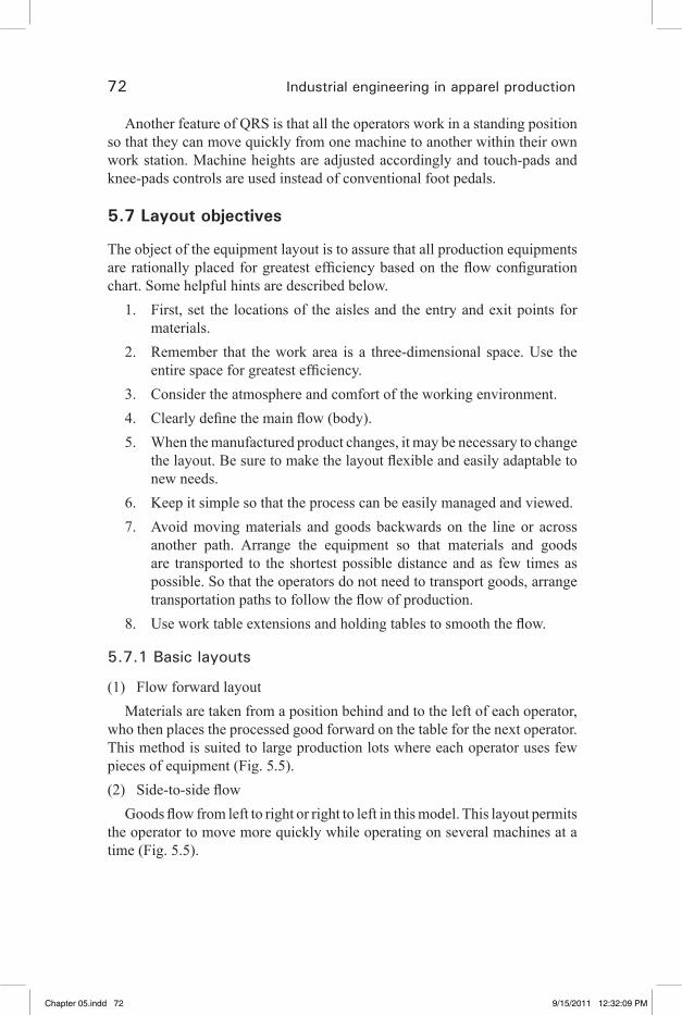
72 Industrial engineering in apparel production
Another feature of QRS is that all the operators work in a standing position so that they can move quickly from one machine to another within their own work station. Machine heights are adjusted accordingly and touch-pads and knee-pads controls are used instead of conventional foot pedals.
5.7 Layout objectives
The object of the equipment layout is to assure that all production equipments arerationallyplacedforgreatestefficiencybasedontheflowconfigurationchart. Some helpful hints are described below.
1. First, set the locations of the aisles and the entry and exit points for materials.
2. Remember that the work area is a three-dimensional space. Use the entirespaceforgreatestefficiency.
3. Consider the atmosphere and comfort of the working environment. 4. Clearlydefinethemainflow(body).5. When the manufactured product changes, it may be necessary to change
thelayout.Besuretomakethelayoutflexibleandeasilyadaptabletonew needs.
6. Keep it simple so that the process can be easily managed and viewed. 7. Avoid moving materials and goods backwards on the line or across
another path. Arrange the equipment so that materials and goods are transported to the shortest possible distance and as few times as possible. So that the operators do not need to transport goods, arrange transportationpathstofollowtheflowofproduction.
8. Useworktableextensionsandholdingtablestosmooththeflow.
5.7.1 Basic layouts
(1) Flow forward layoutMaterials are taken from a position behind and to the left of each operator,
who then places the processed good forward on the table for the next operator. This method is suited to large production lots where each operator uses few pieces of equipment (Fig. 5.5).(2) Side-to-sideflow
Goodsflowfromlefttorightorrighttoleftinthismodel.Thislayoutpermitsthe operator to move more quickly while operating on several machines at a time (Fig. 5.5).
Chapter 05.indd 72 9/15/2011 12:32:09 PM
�� �� �� �� ��
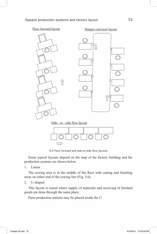
Apparel production systems and factory layout 73
Flow forward layout Hanger conveyor layout
Side - to - side flow layout
5.5 Flow forward and side-to-side flow layouts
Some typical layouts depend on the map of the factory building and the production systems are shown below.1. Linear
The sewing area is in themiddleof thefloorwith cutting andfinishingareas on either end of the sewing line (Fig. 5.6).2. U-shaped
Thislayoutissuitedwheresupplyofmaterialsandreceivingoffinishedgoods are done through the same place.
Parts production stations may be placed inside the U.
Chapter 05.indd 73 9/15/2011 12:32:09 PM
�� �� �� �� ��

74 Industrial engineering in apparel production
The same worker(s) can therefore handle both supplying materials and takingthefinishedgoodsawayfromtheline.Itisthereforeeasiertosupplymaterialsatthesameratefinishedgoodscomeofftheline,andthusmaintaina constant number of goods in progress (Fig. 5.6).3. Comb-shaped
Achieved by combining plural linear lines, each of the part’s lines is also linear, and the parts lines are connected to the main line at the point where the parts are needed (Fig. 5.6).4. Block
Plural units are combined to form individual blocks, each of which comprises the required sewing machines. This format is suited to organization by production groups or to semi-permanent layouts for small lot production lines where the goods being produced change frequently (Fig. 5.6).
Linear U-shaped Comb-shaped Block
5.6 Layout types
5.8 Designing the layout
(1) Prepare a plan view of the production area.Indicatethelocationofpermanentfixtures,includingwalls,pillars,exitsand
entrances, presses, and air conditioning packages.Set the scale according to the size of the factory. In general, a scale of 1:50
or 1:100 is suitable. (2) Using construction paper or paper board, prepare templates for the equipment and tables to be placed.(3)Createenoughtemplatesforallequipmentsused(refertotheflowchart),and record on the templates the type of machine and the location code (Fig. 5.7).
It is convenient to use a different color for each machine type.
Chapter 05.indd 74 9/15/2011 12:32:10 PM
�� �� �� �� ��
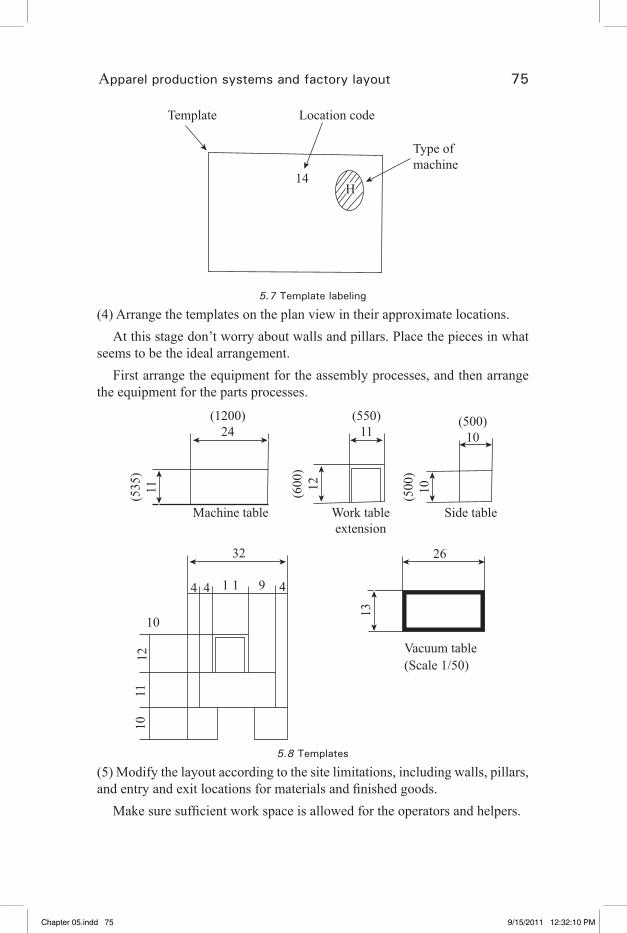
Apparel production systems and factory layout 75
Type ofmachine
Location code
14
Template
H
5.7 Template labeling
(4) Arrange the templates on the plan view in their approximate locations.At this stage don’t worry about walls and pillars. Place the pieces in what
seems to be the ideal arrangement.First arrange the equipment for the assembly processes, and then arrange
the equipment for the parts processes.
1011
12
10
32
4 4 1 1 9 4
26
13
Vacuum table(Scale 1/50)
Machine table Work tableextension
Side table
(500)10
(550)11
(1200)24
(535
)11 (600
)12
(500
)10
5.8 Templates
(5) Modify the layout according to the site limitations, including walls, pillars, andentryandexitlocationsformaterialsandfinishedgoods.
Makesuresufficientworkspaceisallowedfortheoperatorsandhelpers.
Chapter 05.indd 75 9/15/2011 12:32:10 PM
�� �� �� �� ��
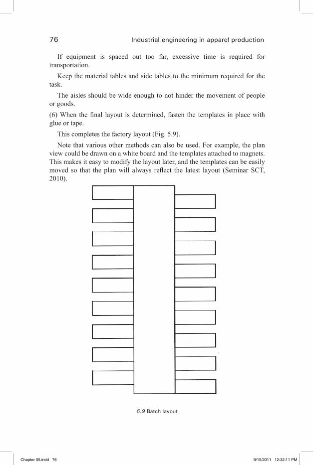
76 Industrial engineering in apparel production
If equipment is spaced out too far, excessive time is required for transportation.
Keep the material tables and side tables to the minimum required for the task.
The aisles should be wide enough to not hinder the movement of people or goods.(6)When thefinal layout isdetermined, fasten the templates inplacewithglue or tape.
This completes the factory layout (Fig. 5.9).Note that various other methods can also be used. For example, the plan
view could be drawn on a white board and the templates attached to magnets. This makes it easy to modify the layout later, and the templates can be easily moved so that the planwill always reflect the latest layout (SeminarSCT,2010).
5.9 Batch layout
Chapter 05.indd 76 9/15/2011 12:32:11 PM
�� �� �� �� ��

Apparel production systems and factory layout 77
5.9 References
1. Glock, R. E. and Kunz, G. I. (2009). Apparel manufacturing analysis, Sewn Product Analysis, 4th edn, Pearson.
2. Babu, V. R. (2006). Garment production systems: An overview, Ind Tex J, 117(1), 71–78.
3. Seminar SCT (2010). Technical workplace skills for the garment industry, Sona School of Garment and Fashion Technology.
Chapter 05.indd 77 9/15/2011 12:32:11 PM
�� �� �� �� ��

79
6Work measurement
6.1 Definition of work measurement
Work measurement is the application of techniques designed to establish the time for a qualified worker to carry out a task at a defined rate of working (Kanawaty, 1992).
6.1.1 Purpose of work measurement
Method study is the principal technique for reducing the work involved, primarily by eliminating unnecessary movement and by substituting good methods for poor ones. Work measurement is concerned with investigating, reducing and eliminating ineffective time, i.e. time during which no effective work is being performed.
Work measurement, as the name suggests, provides management with a means of measuring the time taken in the performance of an operation or series of operations in such a way that ineffective time is shown up and can be separated from effective time. In this way its existence, nature and extent become known where previously they were concealed within the total.
The work measurement not only reveal the existence of ineffective time, it can also be used to set standard times for carrying out the work, so that, if any ineffective time does creep in later, it will immediately be shown up as an excess over the standard time and will thus be brought to the attention of management.
Earlier it was mentioned that method study can reveal shortcomings of design, material and method of manufacture, and affects mainly technical people. Work measurement is more likely to show up management itself and the behavior of the workers.
6.1.2 Uses of work measurement
In the process of setting standards it may be necessary to use work measurement:
Chapter 06.indd 79 9/15/2011 12:32:27 PM
�� �� �� �� ��
80 Industrial engineering in apparel production
1. To compare the efficiency of alternative methods. Other conditions being equal, the method which takes the least time will be the best method.
2. To balance the work of members of teams, in association with multiple activity charts, as nearly as possible, each worker has task taking an equal time to perform.
3. To determine, in association with workers and machine multiple activity charts, the number of machines an operator can run.
The time standards, once set, may be used:4. To provide the basis for production planning and control for the choice
of a better layout and for process planning, and for establishing just-in-time inventory control systems.
5. To provide information that can enable estimates to be made for tenders, selling prices and delivery dates.
6. To set standards of machine utilization and labor performance that can be used for incentive schemes.
7. To provide information for labor-cost control and to enable standard costs to be fixed and maintained.
6.1.3 Basic procedure of work measurement
SELECT The work to be studied.
RECORD All the relevant data relating to the circumstances in which the work is being done, the methods and the elements of activity in them.
EXAMINE The recorded data and the detained breakdown critically to ensure that the most effective method and motions are being used, and unproductive and foreign elements are separated from productive elements.
MEASURE The quality of work involved in each element, in terms of time, using the appropriate work measurement technique.
COMPILE The standard time for the operation, which in the case of stop-watch time study will include time allowances to cover relaxation, personal needs, etc.
DEFINE Precisely the series of activities and method of operation for which the time has been compiled and issue the time as standard for the activities and methods specified.
6.2 Techniques of work measurement
The following are the principal techniques by which work measurement is carried out (Fig. 6.1).
Chapter 06.indd 80 9/15/2011 12:32:27 PM
�� �� �� �� ��

Work measurement 81
Activity sampling• Structured estimating• Time study• Predetermined time standards (PTS)• Standard data•
Select, record, examine and measure
work performed using either one or a
Activity sampling
Structured estimating Time study
Predetermined time standards
Compile Compile
With appropriate allowances to get standard time of operation
To establish standard data banks
quantity of
6.1 Work measurement techniques
6.2.1 Activity sampling
Activity sampling is a method of finding the percentage occurrence of a certain activity by statistical sampling and random observations (Kanawaty, 1992).
6.2.2 Need for activity sampling
Activity sampling (also known as ‘work sampling, ‘ratio-delay study’, ‘random observation method’, ‘snap-reading method’ and ‘observer ratio study’) is, as the name implies, a sampling technique.
In order to obtain a complete and accurate picture of the productive time and idle time of the machines in a specific production area, it would be necessary
Chapter 06.indd 81 9/15/2011 12:32:27 PM
�� �� �� �� ��

82 Industrial engineering in apparel production
to observe continuously all the machines in that area and to record when and why any of the machines were stopped. It would be quite impossible to do this unless a large number of workers spent the whole of their time on this task alone.
As it is not generally possible to do this, the next best method has to be adopted: that of making visits of the factory at random intervals, noting which machines are working and which are stopped, and noting the cause of each stoppage. This is the basis of the work sampling technique. When the sample size is large enough and the observations made are at random, there is quite a high probability that these observations will reflect the real situation, plus or minus a certain margin of error.
Unlike the costly and impractical method of continuous observation, sampling is mainly based on probability. Probability has been defined as “the extent to which an event is likely to occur”.
6.2.3 Conducting the study
6.2.3.1 Determining the scope of the study
Before making our actual observations, it is important that we decide on the objective of our work sampling. The simplest objective is that of determining whether an automatic welt pocket attaching machine is idle or working. In such a case, our observations aim at detecting one of two possibilities only (see Fig. 6.2).
Observations
Automatic welt
pocket – Machine is
working
Automatic welt
pocket – Machine
is idle
6.2 Observation of welt pocket machine
We can extent this simple model to try to find out the cause of the stoppage of the machine (see Fig. 6.3).
Chapter 06.indd 82 9/15/2011 12:32:28 PM
�� �� �� �� ��
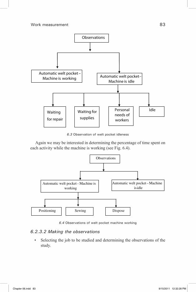
Work measurement 83
Observations
Automatic welt pocket –Machine is working Automatic welt pocket –
Machine is idle
Idle Personal needs of workers
Waiting for
supplies
Waiting
for repair
6.3 Observation of welt pocket idleness
Again we may be interested in determining the percentage of time spent on each activity while the machine is working (see Fig. 6.4).
Observations
Automatic welt pocket – Machine is working
Automatic welt pocket – Machine is idle
Positioning Sewing Dispose
6.4 Observations of welt pocket machine working
6.2.3.2 Making the observations
Selecting the job to be studied and determining the observations of the • study.
Chapter 06.indd 83 9/15/2011 12:32:28 PM
�� �� �� �� ��
84 Industrial engineering in apparel production
Making a preliminary observation to determine the appropriate values of • p and q (p = percentage of idle time, q = percentage of working time).In terms of a chosen confidence level and accuracy range, determining • n (the number of observations needed).Determining the frequency of observations, using random tables.• Designing record sheets to meet the objectives of the study.• Making and recording the observations.• Analyzing the results.•
6.2.4 Principles of activity sampling
Activity sampling has been used to study factory work for more than 40 years. We must know exactly how the operator spends his/her time. This information can be gathered by making frequent short observations while the operator is working. If an operator actually spends 20% of their time waiting for work, then an observer, who makes 100 random glances at him/her, should see him/her working on 80 of those occasions, and waiting on the other 20.
Conversely, if an observer makes enough separate observations to establish a representative sample, and finds one particular activity happening on 20% of the occasions, it is reasonable to assume that the activity accounts for 20% of the operator’s time.
The point about this technique is that the observer can now study 5 or 10 operators together, simply by looking from one to another in turn. The required information can therefore be obtained more economically than by conventional time study methods.Method of carrying out an activity sampling
The observer must first decide what activities he/she is interested in.The next step is to select the group of operators on whom to conduct the
study.The study sheet should be filled out with each operator’s name, operation
and machine type at the head of a column.As soon as the observer is familiar with the appearance of the activities so
that he/she can identify this in an instant, the study can start. With the stop watch running continuously the observer should look at each operator in turn and record the activity.
Each observation is recorded by making a small mark in the appropriate space and these are best accumulated in “five bar gates” for ease in counting later (Table 6.1).
Chapter 06.indd 84 9/15/2011 12:32:28 PM
�� �� �� �� ��

Work measurement 85
The study should be continued until there are at least 500 readings in total – the more readings the more reliable the information obtained.
6.2.5 Analysis of the study
The study should be totaled across and the percentages calculated for each activity, as in the attached example (Table 6.2).
Individual study results may vary somewhat from one to another, largely because production conditions themselves vary from hour to hour and day to day. Under widely varying conditions it is necessary to extend the study by days or weeks in order to obtain a more representative picture of what actually occurs.Table 6.1 Activity sampling record sheet
Date: Observer : Study no.:
Number of observations : 75 Total Percentage
Automatic
welt
pocket –
Machine
is running
llll llll llll llll llll llll llll
llll llll llll llll llll ll
62
82.7
Automatic
welt
pocket –
Machine
is idle
llll llll lll
13
17.3
Chapter 06.indd 85 9/15/2011 12:32:29 PM
�� �� �� �� ��

86 Industrial engineering in apparel production
Table 6.2 Activity sampling record sheet showing utilization and distribution of idle time.
Date: Observer: Study no.
Number of observations: 75 Total Percentage
Automatic welt
pocket – Machine is
running
llll llll llll llll llll llll llll
llll llll llll llll llll ll
62
82.7
Automatic
welt
pocket –
Machine
is
idle
Repair ll 2 2.7
Supplies llll l 6 8.0
Personal l 1 1.3
Idle llll 4 5.3
6.2.6 Advantages of activity sampling
An activity sampling study can be made of several machines and/or operators by a single observer.
It requires fewer man hours and costs less than time study.• Observations may take place over days or weeks, thus decreasing the • effects of day-to-day or week-to-week variations.It provides management with an accurate reflection of factors that affect • production.The observer does not need to be a specially trained work study officer.• Activity sampling can be interrupted at any time, without affecting the • results.
Chapter 06.indd 86 9/15/2011 12:32:29 PM
�� �� �� �� ��
Work measurement 87
It usually requires less time to calculate the results of an activity sampling • study than a time study or production study.
6.2.7 Disadvantages of activity sampling
The disadvantages of activity sampling are as follows:It is not economical for studying a single machine or operator.• Time study permits a finer breakdown of activities and delays than is • possible with activity sampling. The use of performance rating enables time study to determine a more accurate time for the job.It is very rare that a detailed specification of the methods used is made • when conducting an activity sampling investigation. If any operator changes their method, the records are useless.
6.3 Time study
6.3.1 Definition of time study
A work measurement technique for recording the times and rates of working for the elements within specific conditions, and for analyzing the data so as to determine the time necessary for carrying out a job at a defined level of performance (Glock and Kunz, 2009).
Time study evolved from the work of Taylor and was the original work measurement technique.
6.3.2 Time analysis
A scientific management methodF.W. Taylor (1856–1915) developed a famous scientific management method
emphasizing the need for the following three points if high productivity is to be achieved.
(1) Determining the work methodsWork methods should be determined based on scientific research, not
experience.(2) Set fair work goalsThe standard amount of work produced in a day should be decided for each
task based on scientific research.(3) Worker trainingThe best work method should be discovered, and the workers then trained
in that method based on the best method selected according to general applicability.
Chapter 06.indd 87 9/15/2011 12:32:29 PM
�� �� �� �� ��

88 Industrial engineering in apparel production
In other words, Taylor developed a method for breaking a job down into its parts, studying each of these parts to determine the best method, and then measuring the time required for the average worker to complete the task according to the defined method.
This method is known as time study, and has been adopted by many different people and companies.
6.3.4 Steps in making a time study
Get necessary details about the job and the machine.• Make a number of observations before breaking the job down into basic • times.Time 15 cycles – rating from time to time• Convert to basic times • Add the basic times for each element• Give allowances•
Once the engineer performs the method analysis, he is then likely to make a study and document the standard time required to perform the job using the method decided upon. The actual timing that is done is simply a matter of clocking the time the operator requires to perform the job.
The engineer must then do two other things before his time study is completed.
First, he must grade the operator. This means he must decide if the operator is working at a pace that is normal, above normal, or below normal. The objective of the time study is to find the normal time. Then the engineer must apply allowances to the standard time she has developed. These allowances would cover breaks, machine delays and personal time.
Once this is done, a standard can be developed in terms of allowed time to produce a certain number of units in a normal workday.
Time study is the most common technique used by an engineer to set • the targets. However this should be done only after implementing the right method after a perfect method/motion study.The observation recorded for any operation should be taken for one “full • cycle”, i.e., single cycle (SC) time (Start from Pick up of 1st piece and
Stop at pick up of 2nd piece).
Chapter 06.indd 88 9/15/2011 12:32:29 PM
�� �� �� �� ��

Work measurement 89
6.3.5 Time study equipments
Basic time study equipments consist of1. Stop watch2. Study board3. Time study forms
6.3.6 Stop watch
StopwatchesCell phone – Stop watch in your mobile phone.• Seconds – Ordinary watch• Decimal stop watch – Since the great majority of operations in the clothing • industry are less than one minute, the most suitable type of stopwatch is the “decimal minute”.
Why to use a decimal stop watch?
Quite simply, a significant amount of time saved by the engineer who records his study time in centi-minutes compared to seconds. This eliminates the calculation of converting seconds into centi-minutes at a later stage for
use on the calculator. The decimal/minute watch is the most favorite of all kinds of stop watch available by work study engineers. In this watch the main dial is divided into one hundred parts (100) and each division represents 0.01
Chapter 06.indd 89 9/15/2011 12:32:29 PM
�� �� �� �� ��
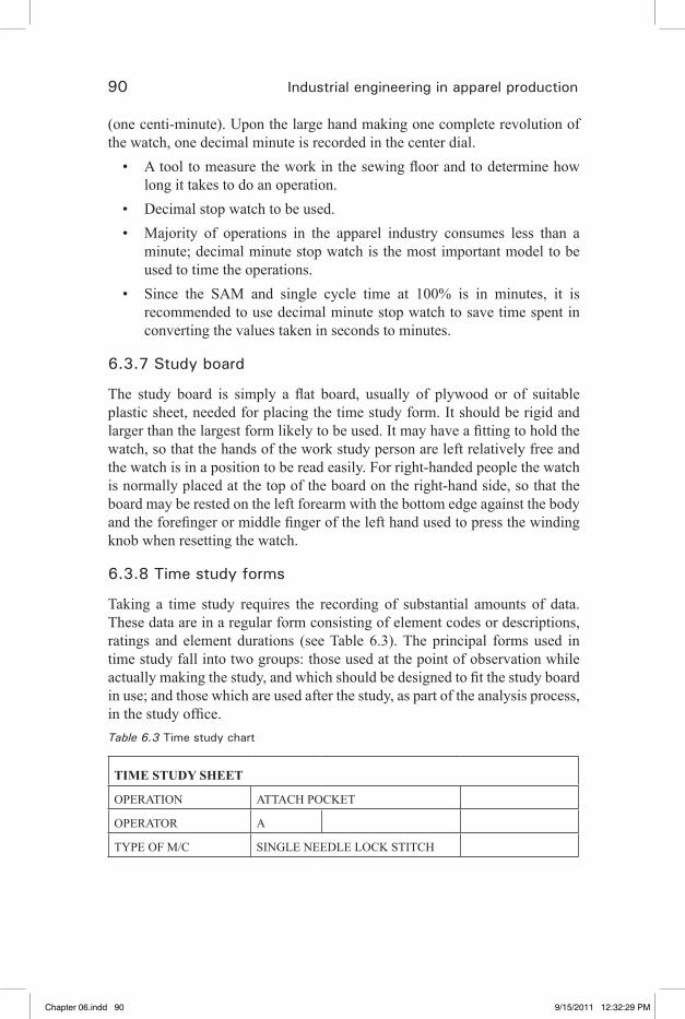
90 Industrial engineering in apparel production
(one centi-minute). Upon the large hand making one complete revolution of the watch, one decimal minute is recorded in the center dial.
A tool to measure the work in the sewing floor and to determine how • long it takes to do an operation.Decimal stop watch to be used. • Majority of operations in the apparel industry consumes less than a • minute; decimal minute stop watch is the most important model to be used to time the operations.Since the SAM and single cycle time at 100% is in minutes, it is • recommended to use decimal minute stop watch to save time spent in converting the values taken in seconds to minutes.
6.3.7 Study board
The study board is simply a flat board, usually of plywood or of suitable plastic sheet, needed for placing the time study form. It should be rigid and larger than the largest form likely to be used. It may have a fitting to hold the watch, so that the hands of the work study person are left relatively free and the watch is in a position to be read easily. For right-handed people the watch is normally placed at the top of the board on the right-hand side, so that the board may be rested on the left forearm with the bottom edge against the body and the forefinger or middle finger of the left hand used to press the winding knob when resetting the watch.
6.3.8 Time study forms
Taking a time study requires the recording of substantial amounts of data. These data are in a regular form consisting of element codes or descriptions, ratings and element durations (see Table 6.3). The principal forms used in time study fall into two groups: those used at the point of observation while actually making the study, and which should be designed to fit the study board in use; and those which are used after the study, as part of the analysis process, in the study office.Table 6.3 Time study chart
TIME STUDY SHEET
OPERATION ATTACH POCKET
OPERATOR A
TYPE OF M/C SINGLE NEEDLE LOCK STITCH
Chapter 06.indd 90 9/15/2011 12:32:29 PM
�� �� �� �� ��

Work measurement 91
DATE ANALYST NAME X
S. no. OT/SCMIN
Rating factor Frequency
1 0.8
2 0.75
3 0.76
4 0.78
5 0.77
6 0.74
7 0.79
8 0.73
9 0.75
10 0.76
TOTAL 7.63
AVERAGE 0.763
OT – Observed time or SC – Single cycle time
6.4 Selecting the job
The following are the possible reasons for the selection of job:1. The job in question is new one.2. A change in material or method of working has been made and a new
time standard is required.3. A complaint has been received from a worker or worker’s representative
about the time standard for an operation.4. A particular operation appears to be a “bottleneck” holding up
subsequent operations.5. Standard times are required before an incentive scheme is introduced.6. A piece of equipment appears to be idle for an excessive time or its
output is low, and it therefore becomes necessary to investigate the method of its use.
Chapter 06.indd 91 9/15/2011 12:32:29 PM
�� �� �� �� ��
92 Industrial engineering in apparel production
7. The job needs studying as a preliminary to making a method study or to compare the efficiency of two proposed methods.
8. The cost of a particular job appears to be excessive, as may be evidenced by a Pareto type of analysis.
6.4.1 Steps in making a time study
1. Obtaining and recording all the information available about the job, the operator and the surrounding conditions, which is likely to affect the carrying out of the work.
2. Record a complete description of the method, breaking down the operation into “elements”.
3. Examining the detailed breakdown to ensure that the most effective method and motions are being used and determining the sample size.
4. Measuring with a timing device (stop watch) and recording the time taken by the operator to perform each element of the operation.
5. At the same time, assessing the effective speed of working of the operator relative to the observer’s concept of the rate corresponding to standard rating.
6. Convert the observed time (SC) into “basic time”.7. Determining the allowances to be made over and above the basic time
for the operation.8. Determining the “standard time “for the operation.
6.4.2 Time study and approach to the worker
(a) One should always speak to the supervisor of the line before approaching the operator that he/she wants to study. This is to ensure that everything is OK before going on with the study.
(b) One should always be polite, well mannered and friendly to the operator without being familiar. He/she should listen with attention to anything that operator mayhave to say about the operation.
(c) Should ask the individual operator’s permission to take the study, even though it has been agreed with the supervisor (There are times when it is not convenient even for the willing operator).
(d) Stand in full view of the operator, but outside his/her normal vision and path of movement.
(e) At the end of the study thank the operator for co-operating and tell the operator that the study is finished.
Chapter 06.indd 92 9/15/2011 12:32:30 PM
�� �� �� �� ��

Work measurement 93
(f) Once the study has been completed, the total time recorded should be compared to the total time taken for the study. If there is a difference of more than 2% the study is not sufficiently accurate, it must be redone.
(g) It is most important to make the operator relax before and during the study.
6.4.3 Breaking the job into elements
Elements should be easily identified with definite beginnings and endings, so that once established they can be repeatedly recognized.
The point at which one element ends and another begins is called a • “breakpoint”,These breakpoints can be either seen or heard.• Elements should be no less that 0.05 of a minute and no longer than • about 0.6 of a minute.
The reasons for breaking a job down into elements are as follows:(a) Variations of speed at which an operator works can be easily seen.(b) To ensure that productive work is separated from unproductive work.(c) To enable a more detailed operation breakdown to be obtained.(d) For future use in compiling standard data.
Circling out unusual happeningsUnusual element times should be ignored at the calculation stage of the
study, but must be recorded when making the study. Some of the unusual happenings are as follows:
(a) Needle break(b) Thread break(c) Bobbin change(d) Thread change
These things are covered by allowances and are therefore not to be included in the basic time.
An element is a distinct part of a specified job selected for convenience of observation, measurement and analysis.
A work cycle is the sequence of elements which are required to perform a job or yield a unit of production. The sequence may sometimes include occasional elements.
Chapter 06.indd 93 9/15/2011 12:32:30 PM
�� �� �� �� ��
94 Industrial engineering in apparel production
6.4.4 Types of elements
(a) Repetitive elementsA repetitive element is an element which occurs in every work cycle of an
operation.(b) Occasional elementsAn occasional element is an element which does not occur in every work
cycle of an operation but which may occur at regular or irregular intervals.(c) Constant elementsA constant element is an element for which the basic time remains constant
whenever it is performed.(d) Variable elementsA variable element is an element for which the basic time varies in relation
to some characteristics of a product, equipment or process, e.g., dimensions, weight, quality, etc.
(e) Manual elementsA manual element is an element performed by a worker.(f) Machine elementsA machine element is an element performed automatically by any process,
physical, and chemical or otherwise that, once started, cannot be influenced by a worker except to terminate it prematurely.
(g) Governing elementsA governing element is an element occupying a longer time within a work
cycle than that of any other element which is being performed concurrently.(h) Foreign elementsA foreign element is an element observed which does not form a part of the
operation(s) being studied. A detailed breakdown into elements is necessary because of the following
reasons:(a) To ensure that productive work (effective time) is separated from
unproductive activity (ineffective time).(b) To permit the rate of working to be assessed more accurately than
would be possible if the assessment were made over a complete cycle. The operator may not work at the same pace throughout the cycle and may tend to perform some elements more quickly than others.
(c) To enable the different types of element to be identified and distinguished, so that each may be accorded the treatment appropriate to its type.
Chapter 06.indd 94 9/15/2011 12:32:30 PM
�� �� �� �� ��
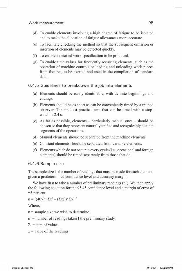
Work measurement 95
(d) To enable elements involving a high degree of fatigue to be isolated and to make the allocation of fatigue allowances more accurate.
(e) To facilitate checking the method so that the subsequent omission or insertion of elements may be detected quickly.
(f) To enable a detailed work specification to be produced.(g) To enable time values for frequently recurring elements, such as the
operation of machine controls or loading and unloading work pieces from fixtures, to be exerted and used in the compilation of standard data.
6.4.5 Guidelines to breakdown the job into elements
(a) Elements should be easily identifiable, with definite beginnings and endings.
(b) Elements should be as short as can be conveniently timed by a trained observer. The smallest practical unit that can be timed with a stop-watch is 2.4 s.
(c) As far as possible, elements – particularly manual ones – should be chosen so that they represent naturally unified and recognizably distinct segments of the operations.
(d) Manual elements should be separated from the machine elements.(e) Constant elements should be separated from variable elements.(f) Elements which do not occur in every cycle (i.e., occasional and foreign
elements) should be timed separately from those that do.
6.4.6 Sample size
The sample size is the number of readings that must be made for each element, given a predetermined confidence level and accuracy margin.
We have first to take a number of preliminary readings (n’). We then apply the following equation for the 95.45 confidence level and a margin of error of ±5 percent:n = [(40√n’ Σx2 – (Σx)2)/ Σx] 2 Where,n = sample size we wish to determinen’ = number of readings taken I the preliminary study. Σ = sum of valuesx = value of the readings
Chapter 06.indd 95 9/15/2011 12:32:30 PM
�� �� �� �� ��

96 Industrial engineering in apparel production
6.5 Standard allowed minute (SAM)
6.5.1 Definition
Standard time is the total time in which a job should be completed at the standard performance. The unit that measures the amount of work to be done by an operator in an operation by the number of minutes it should be completed in (Solinger, 1980).
Standard time is the time required by a worker with standard experience to complete a given task when working at a pace sustainable for an entire workday under normal working conditions and work methods. Standard time thus comprises the following components.
6.5.2 Uses for standard time
Modern management techniques are highly dependent upon time. The “time” factor can be used as follows.
(a) Developing a rational plan(b) A reference point for considering product delivery (c) A tool for developing a production plan(d) Setting an appropriate product price(e) A reference point for negotiating the cost of labor(f) Another factor in profit/loss calculations(g) Improving productivity(h) Discovering problems and places for improvement in the work flow,
including bottlenecks and tasks with lots of waste, irrational procedures, and inconsistencies.
(i) Comparing the time required and movements of two or more operators performing the same task to discover places for improvement.
(j) Checking the effects of work improvements based on the time required.
(k) As the time data for process design(l) To determine operator skill levels
6.5.3 Mechanisms in arriving at SAM
Guess work• Past experience• Stop watch and time study• PMTS•
Chapter 06.indd 96 9/15/2011 12:32:30 PM
�� �� �� �� ��
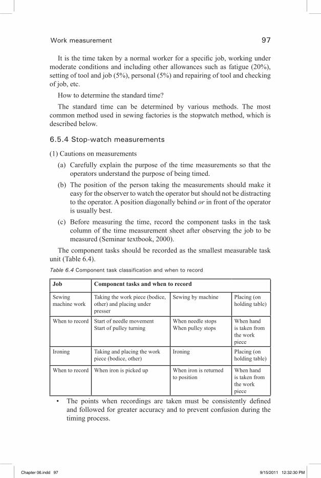
Work measurement 97
It is the time taken by a normal worker for a specific job, working under moderate conditions and including other allowances such as fatigue (20%), setting of tool and job (5%), personal (5%) and repairing of tool and checking of job, etc.
How to determine the standard time?The standard time can be determined by various methods. The most
common method used in sewing factories is the stopwatch method, which is described below.
6.5.4 Stop-watch measurements
(1) Cautions on measurements(a) Carefully explain the purpose of the time measurements so that the
operators understand the purpose of being timed. (b) The position of the person taking the measurements should make it
easy for the observer to watch the operator but should not be distracting to the operator. A position diagonally behind or in front of the operator is usually best.
(c) Before measuring the time, record the component tasks in the task column of the time measurement sheet after observing the job to be measured (Seminar textbook, 2000).
The component tasks should be recorded as the smallest measurable task unit (Table 6.4).Table 6.4 Component task classification and when to record
Job Component tasks and when to record
Sewing machine work
Taking the work piece (bodice, other) and placing under presser
Sewing by machine Placing (on holding table)
When to record Start of needle movement Start of pulley turning
When needle stops When pulley stops
When hand is taken from the work piece
Ironing Taking and placing the work piece (bodice, other)
Ironing Placing (on holding table)
When to record When iron is picked up When iron is returned to position
When hand is taken from the work piece
The points when recordings are taken must be consistently defined • and followed for greater accuracy and to prevent confusion during the timing process.
Chapter 06.indd 97 9/15/2011 12:32:30 PM
�� �� �� �� ��
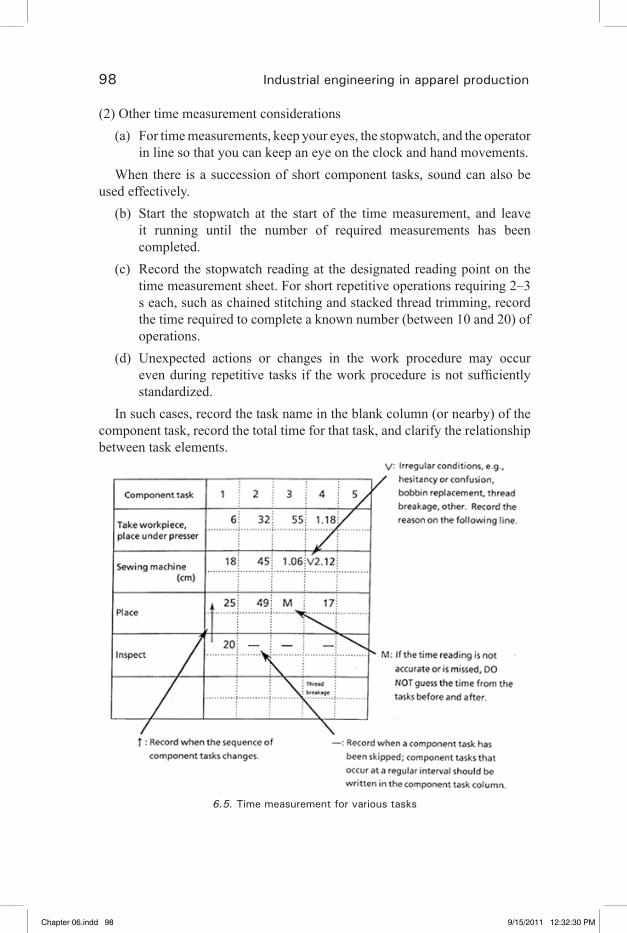
98 Industrial engineering in apparel production
(2) Other time measurement considerations(a) For time measurements, keep your eyes, the stopwatch, and the operator
in line so that you can keep an eye on the clock and hand movements.When there is a succession of short component tasks, sound can also be
used effectively. (b) Start the stopwatch at the start of the time measurement, and leave
it running until the number of required measurements has been completed.
(c) Record the stopwatch reading at the designated reading point on the time measurement sheet. For short repetitive operations requiring 2–3 s each, such as chained stitching and stacked thread trimming, record the time required to complete a known number (between 10 and 20) of operations.
(d) Unexpected actions or changes in the work procedure may occur even during repetitive tasks if the work procedure is not sufficiently standardized.
In such cases, record the task name in the blank column (or nearby) of the component task, record the total time for that task, and clarify the relationship between task elements.
6.5. Time measurement for various tasks
Chapter 06.indd 98 9/15/2011 12:32:30 PM
�� �� �� �� ��

Work measurement 99
(3) Number of measurementsThe number of measurements taken will vary with the purpose for which
the results will be used. If for defining the standard time or improving work methods, measurements should, in principle, be taken ten times (five or more times for repetitive tasks performed at a steady rhythm).(4) Record working conditions
Work movements and work time are obtained as the results of various work conditions, and can therefore be used as reference for similar jobs and component tasks. It is important in this case to record the time measurements so that other people can understand the conditions under which the readings were obtained.(5) Calculating and organizing time measurements
(a) When time measurements are completed, write the time for each component task in red pencil on the bottom row of the measurements (see Fig. 6.5).
The time is used to calculate the difference between measurements. (b) Circle times (indicated with a V) that are clearly abnormal, and do
not include these values when calculating the average time (Seminar textbook, 2000).
(c) In the averages column of the time measurement sheet, record the average times to one decimal point.
(d) Total the times in the component task averages column, and record to the totals column. When there are two pieces per garment, e.g. pockets, and the time measurement was for only one pocket, multiply the measurement by two to obtain the actual time per garment for both pieces.
(e) For short repetitive operations requiring 2–3 s each, such as chained stitching and stacked thread trimming operations, divide the measured time by the number of operations per garment to obtain the time per garment, and record this figure in the actual time column.
(f) Determine and record an allowance factor. (g) Calculate the standard time as: Standard time = actual time (Basic
time) + allowance time (Fig. 6.6).(h) Standard time is not constant and unchanging. It is necessary to
periodically reassess the standard time to accurately reflect the current work conditions as workplace improvements and the introduction of new equipment rationalize work procedures.
Chapter 06.indd 99 9/15/2011 12:32:30 PM
�� �� �� �� ��
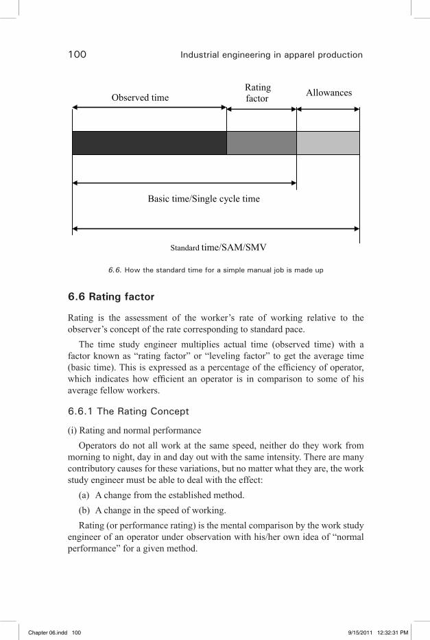
100 Industrial engineering in apparel production
Observed timeRating factor
Allowances
Basic time/Single cycle time
Standard time/SAM/SMV
6.6. How the standard time for a simple manual job is made up
6.6 Rating factor
Rating is the assessment of the worker’s rate of working relative to the observer’s concept of the rate corresponding to standard pace.
The time study engineer multiplies actual time (observed time) with a factor known as “rating factor” or “leveling factor” to get the average time (basic time). This is expressed as a percentage of the efficiency of operator, which indicates how efficient an operator is in comparison to some of his average fellow workers.
6.6.1 The Rating Concept
(i) Rating and normal performanceOperators do not all work at the same speed, neither do they work from
morning to night, day in and day out with the same intensity. There are many contributory causes for these variations, but no matter what they are, the work study engineer must be able to deal with the effect:
(a) A change from the established method.(b) A change in the speed of working.Rating (or performance rating) is the mental comparison by the work study
engineer of an operator under observation with his/her own idea of “normal performance” for a given method.
Chapter 06.indd 100 9/15/2011 12:32:31 PM
�� �� �� �� ��
Work measurement 101
(ii) Definition of normal performanceNormal performance is the working rate of the average worker working
under capable supervision, but without the stimulus of an incentive wage payment plan. This pace can be easily maintained day after day, without undue physical or mental fatigue, and is characterized by the fairly steady exertion of reasonable effort.
Normal performance is often represented in the following way:A man walking on the level at 4.8 km per hour dealing a pack of 52 cards
in 37.5 s.Comparing the observed performance with normal performance:The question most often asked with regard to rating is “How is it possible
to compare the observed rate of working with the theoretical standard?” The answer can be given only after the long practice.
To revert to the rating exercise on walking, most people would be able to judge the rate at which a man is walking. They would start classifying rates of walking as slow, average or fast.
The initial training is on the walking and card dealing exercises, and then as industrial operation is more complex, he/she practices rating industrial operations either on film or on the factory floor, under supervision. The rating skill, however, is achieved by constant practice.
How the rating factor is used?If the work study engineer decides that the operation he/she is observing is
being performed less effectively than his/her idea of standard, he/she will use a factor of less than 100, say 75 or 80, or whatever he/she considers represents a proper assessment.
If, on the other hand, he/she decides it is being done more effectively, he/she gives a rating assessment of 90–95, etc. It is a usual practice to round off the ratings to the nearest multiple of 5 on the scale.
With proper training and continual practice, a competent work study engineer can assess the effort of an operator on a 5 point basis from about a 60 to 125 rating. Outside these values, the accuracy of rating diminishes, but most operators’ ratings fall within this range.
6.6.2 Performance rating
Performance rating is the process during which the time study engineer compares the performance of the operator under observation with his own concept of normal performance.
Chapter 06.indd 101 9/15/2011 12:32:31 PM
�� �� �� �� ��
102 Industrial engineering in apparel production
Observed performancePerformance rating = 100Normal performance
×
The concept of normal performance must be such that the time standards set from it and must be within the capacity of the majority of workers in the enterprise.
Standard performance (normal performance) is the rate of output which qualified workers will naturally achieve without over-exertion as an average over the working day or shift, provided that they know and adhere to the specified method and provided that they are motivated to apply themselves to their work. This performance is denoted as 100 on the standard rating and performance scales.
The rate of working most generally accepted in the UK and US as corresponding to the standard rating is equivalent to the speed of motion of the limbs of a man of average physique walking without a load in a straight line on level ground at a speed of 4 miles an hour (6.4 km/h). Another accepted example of working at the standard rate is dealing a pack of 52 playing cards in 0.375 minutes.
6.6.3 Methods of rating
Following are the important methods used for performance rating:1. Speed rating2. Westinghouse system of rating3. Synthetic rating4. Objective rating5. Physiological evaluation of performance rating
1. Speed ratingThis rating procedure consists of judging the pace/speed of the operator’s
movement in relation to a normal pace and is noted as a factor. This rating is applied to each element and observed time for each element is multiplied by this factor (the ratio of observed speed to expected speed) so as to get the basic time (normal time) for the element.2. Westinghouse system of rating
A four system of performance rating was developed at Westing house. These factors are as follows:
(a) Skill(b) Effort
Chapter 06.indd 102 9/15/2011 12:32:31 PM
�� �� �� �� ��

Work measurement 103
(c) Conditions(d) ConsistencyAs scale of numerical value for each factor was supplied in the tabular
form, the worker was watched while working and given a value from these tables shown in Table 6.5. The time obtained from time study is then leveled by applying the sum of the ratings of all the four factors.
For example, if the observed time for an operator was 1.50 minutes and if the ratings are as follows:
Good skill C1 +0.06 Excellent efforts D2 +0.08 Average conditions D +0.00 Good consistency C +0.01 ------------------------------------ Total +0.15 ------------------------------------The basic time for that operation would be 1.50 × 1.15 = 1.72 minutes.
Table 6.5 Westinghouse tables
Skill Efforts+0.15 A1+0.13 A2 Super skill
+0.13 A1+0.12 A2 Excessive
+0.11 B1+0.08 B2 Excellent
+0.10 B1+0.08 B2 Excellent
+0.06 C1+0.03 C2 Good
+0.05 C1+0.02 C2 Good
+0.00 D Average +0.00 D Average−0.05 E1−0.10 E2 Fair
−0.04 E1−0.08 E2 Fair
−0.16 F1−0.22 F2 Poor
−0.12 F1−0.17 F2 Poor
Conditions Consistency+0.06A Ideal +0.04A Perfect+0.04B Excellent +0.03B Excellent+0.02C Good +0.01C Good+0.00D Average +0.00D Average−0.03E Fair −0.02E Fair−0.07F Poor −0.04F Poor
3. Synthetic rating
Chapter 06.indd 103 9/15/2011 12:32:31 PM
�� �� �� �� ��
104 Industrial engineering in apparel production
In this method, performance of the worker is rated from the values already known by PMTS (Predetermined motion and time study). In this procedure, time study is done in the usual manner and then actual time obtained for certain elements from this study is compared with that of known standards. The ratio of standard time of a particular element to that of observed time of the same element is the rating factor for the study. The rating factor for the study is the average of rating factors obtained for different elements of the study. Efforts must be obtained to determine the rating factors for as many elements as possible. In this method, it is assumed that performance for the whole of the study will be same as that obtained in these elements.If R = Performance rating factor P = Predetermined standard for an element A = Average of actual time obtained in the time study for that
element.Then R = P/A4. Objective rating
In this method, rating is done in two stages, in first stage, operators speed is rated by observing speed of movement or rate of activity, and no attempt is paid for the job difficulties. After the speed rating is made, in the second stage, an allowance of a secondary adjustments is added to the pace rating by considering the job difficulties. Job difficulties are divided into six classes. A table provides the percentage of adjustments to be made for each of these six factors. These factors are as follows:
(i) Amount of body used(ii) Foot pedals(iii) Bimanualness(iv) Eye–hand co-ordination(v) Handling requirements(vi) WeightFor example, if the selected time for an element is 0.30 minutes, the pace
rating is 1.10% and if the sum of all secondary adjustments amount to 20%, then the normal time will be = 0.30 × 1.10 × 1.20 = 0.396 min.
6.7 Allowances
Before it is possible to complete and issue that standard time for a job, it is necessary to add to the basic time certain allowances.
Chapter 06.indd 104 9/15/2011 12:32:31 PM
�� �� �� �� ��
Work measurement 105
The reason for adding these allowances is that the work study engineer has only been considering the productive work of the operator and has not taken into account the periods of rest that are required by the operator to enable the operator to recover from the energy expended, nor the time that he/she needs to allow attention to personal needs.
There are certain special allowances for cleaning or re-threading machines which must be taken into account or the work study officer will not be issuing accurate times.
Reason to add allowances to the basic time When a worker works for a long duration, there is no consistency in her • pace. Also she requires some attention to personal needs, time is required for fixing needle in case of needle breakage, rethreading the needle in case of thread breakage, time lapsed due to machine breakdown, etc.The standard time is arrived at by adding up some allowances to the • basic time. This will be a correct measure to set daily targets which are more practical or reliable.
To get the standard time, a proper allowance must be added consisting the working conditions. While deciding the quantum (generally in terms of percentage) of allowance to be added to the normal time, following types of allowance are considered:
1. Machine allowances2. Relaxation allowance3. Interference allowance4. Process allowance5. Contingency allowance6. Special allowance
(1) Machine allowances – This covers Thread cone or tube change• Thread and needle breakage• Adjusting tension• Small problems in machine•
The following chart (see Table 6.6) shows the allowance value for different kind of machines.
Chapter 06.indd 105 9/15/2011 12:32:31 PM
�� �� �� �� ��

106 Industrial engineering in apparel production
Table 6.6 Machine allowances
Type of machine Allowance Type of machine AllowanceSingle needle lock stitch 12.5% Multi-needle chain stitch 16%Double needle lock stitch 14% Safety stitch (5TOL/FL) 18%Single needle chain stitch 13% Bar tack stitch 12%Overlock stitch 12%
(2) Relaxation allowancePeople are not machines and they need to go the toilet, scratch, blow their
nose, etc. Relaxation and fatigue allowances are provided to give the operator/worker the opportunity to recover from the effort of doing his/her work, and to allow for attention to personal needs. The relaxation and fatigue allowance is given to every operation.
Recommended allowances for personal and fatigue allowances in the sewing trade are set at 11% for sitting jobs and 13% for standing.
Relaxation allowance is an addition to the basic time intended to provide the worker with the opportunity to recover from the physiological and psychological effects of carrying out specified work under specified conditions and to allow attention to personal needs. The amount of this allowance depends upon the nature of the job and includes the following two categories.
(a) Personal need allowanceIt provides for the necessity to go away from the work place to attend the
personal needs such as washing, going to lavatory, getting a drink, etc. It is commonly taken as 5% for male and 7% for female worker.
(b) Fatigue allowanceFatigue allowance is provided to recover a worker, from the physical efforts
of carrying out work. It consists of:(i) A constant portion (the minimum or basic fatigue allowance) which
must be adequate for a worker who carries out the job while seating, engaged on light work in an ideal working conditions. This is generally considered as 4% for both men and women.
(ii) A variable portion is added when the working conditions are severe. It is based on factors which vary with the working conditions. These factors are as follows:(a) Standing or other abnormal position (2%)(b) Use of force (10–20%) (c) Light
Chapter 06.indd 106 9/15/2011 12:32:31 PM
�� �� �� �� ��

Work measurement 107
(d) Atmospheric condition (10–20%)(e) Visual strain (4–8%)(f) Manual strain(g) Mental strain(h) Loud noise(i) Vibration
(3) Interference allowanceWhen one worker is attending more than one machine, then interference is
the time for which one or more machine units remain idle while the operator is occupied with the work on other machine units. The allowance provided to compensate this idleness due to interference is known as interference allowance.(4) Process allowance
This is an allowance provided to compensate for enforced idleness during a process. This includes loss of time due to:
(i) no work(ii) power failure(iii) faulty material(iv) faulty tools or equipments
(5) Contingency allowanceA contingency allowance should not be greater than 5% and should only
be given in cases where the work study officer is absolutely satisfied that they are justified. The contingency allowances should be expressed as a percentage of the basic time.
This is an allowance of time to meet legitimate, irregular and infrequent items of works or delays which cannot economically be measured correctly. It is usually taken as less than 5%.(6) Special allowance
These allowances are decided as a policy matter of management. These are allowed for activities which are normally not a part of the operation cycle bur are essential for satisfactory performance of work. These include for the following items:
(i) Start up(ii) Cleaning(iii) Shut down
Chapter 06.indd 107 9/15/2011 12:32:31 PM
�� �� �� �� ��
108 Industrial engineering in apparel production
(iv) Set up(v) Dismantling allowance (vi) Change over(vii) Reject allowance(viii) Excess work allowance(ix) Learning allowance(x) Training allowance(xi) Implementation allowance(xii) Small batch allowance(xiii) Tool changing and regrinding
Bundle handling allowanceBundle handling can, if required, be expressed as a percentage and
added as an allowance.
6.8 Other methods to set time standards
(a) Pre-determined motion–time system (PMTS) PMTS is a pre-determined motion–time system (PMTS). It was designed
specifically for the sewn products industry, its primary function is to rationalize manufacturing methods and to produce an accurate evaluation of the time required to perform a specific task or function.
PMTS system specifically designed for the sewing industry. It is a method study technique which identifies specific handling and swing elements, each one of which has a pre-determined time, by adding each of these elements together and adding the required allowances one is able to establish a standard time for the operation. The standard times established in this way are equally fair and form the basis on which the following can be achieved.
Establish the best method to do the operation• Measure the performance of all operators; this should include helpers • and all finishing operationsCapacity planning and factory loading• Line balancing• Production targets• Incentive payment systems• Operator training (through standardized methods)•
Chapter 06.indd 108 9/15/2011 12:32:31 PM
�� �� �� �� ��

Work measurement 109
PMTS has to be implemented in the correct manner. Training is a key factor of success and should include all levels of personnel from the shop floor to the boardroom commitment is required from all levels within the business.
PMTS produces standard times that are equally fair throughout the production environment.
Jobs or job methods performed or used by everyone are broken down into the required action elements to predefine a time cost based on the properties of the action element and the conditions. It is generally called the “predetermined time standard” method. Method time measurement (MTM) and work factor (WF) methods are also known.(b) Standard reference method
Time measurements are not actually taken. Rather, data collected in the past is organized to define a standard model. The job conditions are then applied to this standard model to obtain the standard time.(c) Actual results method
The time is determined based on past actual measurements and the production quantity.Illustrations:
If an operator is working on an operation as follows, we will calculate the SAM for the operation.
TIME STUDY SHEET
Operation Attach pocket
Operator A
Type of m/c Single needle lock stitch
Date 20th May 2009
Analyst name X
S. No. OT/ SC Rating factor Frequency
1 0.8 0.8 1
2 0.75 0.85 1
3 0.76 0.85 1
4 0.78 0.8 1
5 0.77 0.75 1
6 0.74 0.8 1
Chapter 06.indd 109 9/15/2011 12:32:31 PM
�� �� �� �� ��

110 Industrial engineering in apparel production
7 0.79 0.85 1
8 0.73 0.8 1
9 0.75 0.8 1
10 0.76 0.8 1
Total 7.63
Average 0.763 0.81 1
Basic time/SC 0.618
(Avg OT X RF)
MA 12.50%
PF 20%
BH 0.03
OT – Observed time or SC – Single cycle time
SAM = 0.87
[(BT × (1 + MA) × (1 + PF))] + [BH × (1 + PF)]
Cycle checksA cycle check is a brief time study with the purpose of setting a target
quickly, or checking whether an operator is capable of achieving a standard time.
The cycle time is the time taken by the operator to perform one cycle of the operation, i.e., time between pick-up and dispose.
Conduct a cycle check according to the following steps:Select the operation/s to be studied and enter the details on an appropriate • form.Watch five cycles of each operation, noting the time for each complete • cycle.Calculate the average cycle time for each operation.• Compare cycle time to the issued basic time. •
Exercises Calculate SAM for the following observations:
(1) For an operator working on an operation using single needle lock stitch
Chapter 06.indd 110 9/15/2011 12:32:31 PM
�� �� �� �� ��
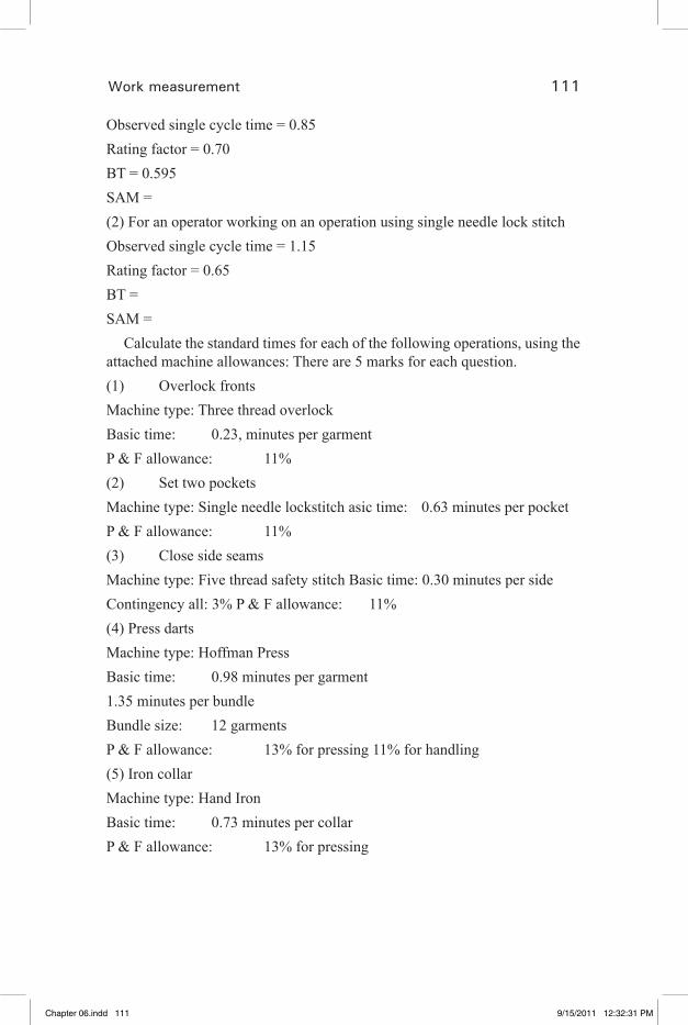
Work measurement 111
Observed single cycle time = 0.85Rating factor = 0.70BT = 0.595SAM = (2) For an operator working on an operation using single needle lock stitch Observed single cycle time = 1.15Rating factor = 0.65 BT = SAM =
Calculate the standard times for each of the following operations, using the attached machine allowances: There are 5 marks for each question.(1) Overlock frontsMachine type: Three thread overlockBasic time: 0.23, minutes per garmentP & F allowance: 11%(2) Set two pocketsMachine type: Single needle lockstitch asic time: 0.63 minutes per pocketP & F allowance: 11%(3) Close side seamsMachine type: Five thread safety stitch Basic time: 0.30 minutes per sideContingency all: 3% P & F allowance: 11%(4) Press dartsMachine type: Hoffman PressBasic time: 0.98 minutes per garment1.35 minutes per bundleBundle size: 12 garmentsP & F allowance: 13% for pressing 11% for handling(5) Iron collarMachine type: Hand IronBasic time: 0.73 minutes per collarP & F allowance: 13% for pressing
Chapter 06.indd 111 9/15/2011 12:32:31 PM
�� �� �� �� ��

112 Industrial engineering in apparel production
6.9 References
1. Kanawaty, G. (1992). Introduction to Work Study, 4th edn, International Labour Organization.
2. Solinger, J. (1980). Apparel Manufacturing Handbook, Analysis, Principles and Practice, Van nostrand Reinhold Company.
3. Glock, R. E. and Kunz, G. I. (2009). Apparel Manufacturing Analysis, Sewn Product Analysis, 4th edn, Pearson.
4. Seminar Textbook (2000). Sewing factory management technicians, Brother Sewing Technology Center.
Chapter 06.indd 112 9/15/2011 12:32:31 PM
�� �� �� �� ��
113
7Application of IE techniques in garment industry
7.1 Capacity study
Capacity study is similar to time study where the operator will be timed, but the purpose is not to arrive at a time standard, rather to find out the operator’s potential/performance level.
Here we are measuring the performance and potential that an operator should attain; if he works on the operation continuously at same pace and same method as observed during the study.It means that the operator is capable of achieving the performance measured by the study (Seminar SCT, 2010).
7.2 How to perform capacity study?
1. Get necessary details of the operation like job and machine.2. Once the best method is implemented, take ten single cycle (SC)
observations with the help of stop watch.3. Once the readings are noted, calculate the average SC observation and
arrive at the capacity of the operator.4. The cycle consisting of breakdown times, such as machine delay,
handling bundles, etc., should not be considered for calculating average SC time during capacity study.
5. The reason behind this is that the above delays will occur irrespective of the operators’ capability or capacity, so these delays cannot be considered to be a measure of operator’s capacity.
6. However these delays will definitely reduce the operator’s actual performance for the day.
Chapter 07.indd 113 9/29/2011 10:14:05 AM
�� �� �� �� ��

114 Industrial engineering in apparel production
Handling bundles
Machine delays
(Thread breakage, bobbin
change, thread change, etc.)
Breaks and personal time
REDUCTION
OF
OPERATOR’S
PEFORMANCE
Illustration on capacity study calculation:For an operator working in an operation where the SAM is 0.45 min, SC@100% is 0.41 min,Type of machine used is SNLS and average observed SC time is 0.65 min.Quota (Target at 100%) is = Working time in minutes/SAMShift duration – 8 h = 480 min = 480/0.45 = 1066 pieces.SC efficiency is = SC@100%/Average observed SC time = 0.41/0.65 = 0.63 = 63%.Capacity per day = Quota × SC efficiency = 1066 × 0.63 = 671 piecesCapacity per hour is = Capacity per day/No. of working hours = 671/8 = 83 pieces.
7.2.1 Benefits of capacity study
Check targets• Motivate operators• Measure section production capability•
7.2.2 Check targets
When the operation bulletin is prepared, the targets are set based on a • planned efficiency, say 65%. But it would be impossible to expect all the operators in a line to work at same efficiency.Once capacity study is done, the targets of every operator on an operation • can be checked with the capacity and proper balancing decisions can be taken to ensure the daily target.
Chapter 07.indd 114 9/29/2011 10:14:06 AM
�� �� �� �� ��

Application of IE techniques in garment industry 115
7.2.3 Motivate operators
The operators should be motivated to perform at the highest level • possible based on the capacity study data.Most of the operators perform low because they do not realize/know • their strength in the work. The operators should be told about their capacity and motivate in • achieving this.A capacity study is a means of showing an operator that she is capable • of more than she realizes.
7.2.4 Measure section production capability
By measuring individual operator capacities, the line managers can • determine the overall capacity of their sections.This is useful to a supervisor in setting production and performance • goals for her section.
Exercise For an operator working in an operation where the SAM is 0.85
min,SC@100% is 0.78 min, type of machine used is SNLS and average observed SC time is 0.921 min
Calculate –Quota (Target at 100%) SC efficiency Capacity per day
7.3 Operator performance
Basically the operator performance can be monitored with the help of three efficiency factors.
(1) Single cycle efficiency(2) On-standard efficiency(3) Global efficiency
7.3.1 Single cycle efficiency
Target single cycle time in minutes (SC@100%)=
Average observed single cycle time in minutes (SC average)Here we are considering the cycle time only.
Chapter 07.indd 115 9/29/2011 10:14:06 AM
�� �� �� �� ��
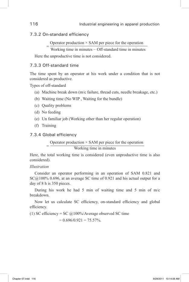
116 Industrial engineering in apparel production
7.3.2 On-standard efficiency
= Operator production × SAM per piece for the operation
Working time in minutes − Off-standard time in minutesHere the unproductive time is not considered.
7.3.3 Off-standard time
The time spent by an operator at his work under a condition that is not considered as productive.Types of off-standard
(a) Machine break down (m/c failure, thread cuts, needle breakage, etc.)(b) Waiting time (No WIP , Waiting for the bundle)(c) Quality problems(d) No feeding(e) Un familiar job (Working other than her regular operation)(f) Training
7.3.4 Global efficiency
= Operator production × SAM per piece for the operation
Working time in minutes Here, the total working time is considered (even unproductive time is also considered).Illustration
Consider an operator performing in an operation of SAM 0.821 and SC@100% 0.696, at an average SC time of 0.921 and his actual output for a day of 8 h is 350 pieces.
During his work he had 5 min of waiting time and 5 min of m/c breakdown.
Now let us calculate SC efficiency, on-standard efficiency and global efficiency.(1) SC efficiency = SC @100%/Average observed SC time = 0.696/0.921 = 75.57%.
Chapter 07.indd 116 9/29/2011 10:14:06 AM
�� �� �� �� ��
Application of IE techniques in garment industry 117
(2) On-standard efficiency =
(Operator production × SAM per piece) Working time in min – Off-standard time in min) = (350 × 0.921)/ (480 – 20) = 70%(3) Global efficiency = (Operator production × SAM per piece) (Working time in min) = (350 × 0.921)/480 = 67.15%.
The operator should be developed by following 3 basic points:1. Increase the single cycle efficiency to 100%.2. Reduce the difference between on-standard efficiency and single cycle
efficiency.3. Reduce the difference between global efficiency and on-standard
efficiency.
7.4 Follow-ups
This requires that someone checks on and stays with something until desired results are achieved.
Any project being implemented successfully may fail if the follow-up is not consistent.
Here we are going to concentrate on operator performance follow up (Seminar textbook, 2000).
7.4.1 Benefits of operator follow-ups
1. Improve performance (motivate)2. Prove job quotas3. Spot troubles
7.4.2 Types of follow-ups
1. Bundle by bundle follow-up2. Bundle diagnosis
7.4.3 Bundle by bundle follow-up
This follow-up is done when the operator’s on-standard efficiency is much less than his single cycle efficiency in that operation.
Single cycle (SC) efficiency is arrived considering the cycle time taken by the operator to complete each piece. Whereas the on-standard efficiency is
Chapter 07.indd 117 9/29/2011 10:14:07 AM
�� �� �� �� ��
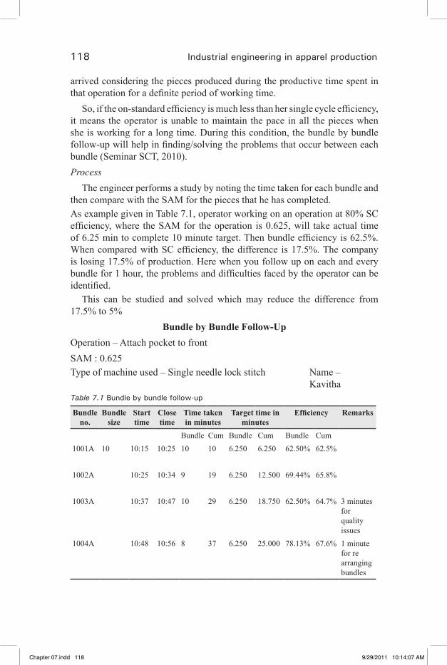
118 Industrial engineering in apparel production
arrived considering the pieces produced during the productive time spent in that operation for a definite period of working time.
So, if the on-standard efficiency is much less than her single cycle efficiency, it means the operator is unable to maintain the pace in all the pieces when she is working for a long time. During this condition, the bundle by bundle follow-up will help in finding/solving the problems that occur between each bundle (Seminar SCT, 2010).Process
The engineer performs a study by noting the time taken for each bundle and then compare with the SAM for the pieces that he has completed.As example given in Table 7.1, operator working on an operation at 80% SC efficiency, where the SAM for the operation is 0.625, will take actual time of 6.25 min to complete 10 minute target. Then bundle efficiency is 62.5%. When compared with SC efficiency, the difference is 17.5%. The company is losing 17.5% of production. Here when you follow up on each and every bundle for 1 hour, the problems and difficulties faced by the operator can be identified.
This can be studied and solved which may reduce the difference from 17.5% to 5%
Bundle by Bundle Follow-UpOperation – Attach pocket to frontSAM : 0.625Type of machine used – Single needle lock stitch Name – Kavitha Table 7.1 Bundle by bundle follow-up
Bundle no.
Bundle size
Start time
Close time
Time taken in minutes
Target time in minutes
Efficiency Remarks
Bundle Cum Bundle Cum Bundle Cum 1001A 10 10:15 10:25 10 10 6.250 6.250 62.50% 62.5%
1002A 10:25 10:34 9 19 6.250 12.500 69.44% 65.8% 1003A 10:37 10:47 10 29 6.250 18.750 62.50% 64.7% 3 minutes
for quality issues
1004A 10:48 10:56 8 37 6.250 25.000 78.13% 67.6% 1 minute for re arranging bundles
Chapter 07.indd 118 9/29/2011 10:14:07 AM
�� �� �� �� ��
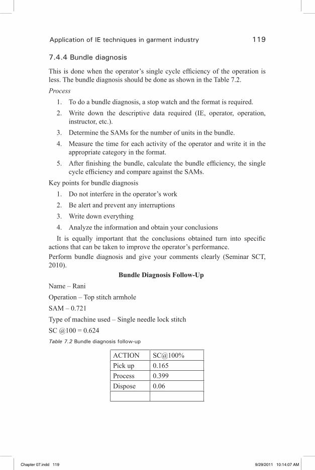
Application of IE techniques in garment industry 119
7.4.4 Bundle diagnosis
This is done when the operator’s single cycle efficiency of the operation is less. The bundle diagnosis should be done as shown in the Table 7.2.Process
1. To do a bundle diagnosis, a stop watch and the format is required.2. Write down the descriptive data required (IE, operator, operation,
instructor, etc.).3. Determine the SAMs for the number of units in the bundle.4. Measure the time for each activity of the operator and write it in the
appropriate category in the format.5. After finishing the bundle, calculate the bundle efficiency, the single
cycle efficiency and compare against the SAMs.Key points for bundle diagnosis
1. Do not interfere in the operator’s work2. Be alert and prevent any interruptions3. Write down everything4. Analyze the information and obtain your conclusions It is equally important that the conclusions obtained turn into specific
actions that can be taken to improve the operator’s performance.Perform bundle diagnosis and give your comments clearly (Seminar SCT, 2010).
Bundle Diagnosis Follow-UpName – RaniOperation – Top stitch armholeSAM – 0.721Type of machine used – Single needle lock stitchSC @100 = 0.624Table 7.2 Bundle diagnosis follow-up
ACTION SC@100%Pick up 0.165Process 0.399Dispose 0.06
Chapter 07.indd 119 9/29/2011 10:14:07 AM
�� �� �� �� ��

120 Industrial engineering in apparel production
Piece no. Bundle handling
Observed SC readingsPickup Process Dispose
1 0.16 0.315 0.521 0.0702 0.305 0.512 0.0753 0.312 0.513 0.0714 0.309 0.509 0.0725 0.311 0.511 0.0766 0.32 0.485 0.0707 0.31 0.47 0.0688 0.285 0.45 0.0729 0.275 0.412 0.06910 0.152 0.26 0.41 0.068
Total 0.312 3.002 4.793 0.711Average time
taken 0.0312 0.3002 0.4793 0.0711
Target time 0.03 0.165 0.399 0.06Efficiency 96.15% 54.96% 83.25% 84.39%
Comment – The efficiency of operator during pick up was less compared with process and dispose.
This is the objective of bundle diagnosis.
7.5 Work in process (WIP)
The semi-finished or finished goods which transported from one work station to next work station are called work in progress.
WIP is made up of all garments and their parts that are not completely • finished.It can be measured in units (pieces) or time (minutes).•
For example – if an operator a takes 0.8 minute per piece to stitch and if she has 3 bundles of 10 pieces each to be processed, then the WIP in that workstation is 30 pieces or 24 minutes.
7.5.1 Need to control WIP
Two major cost areas can be reduced if WIP is controlled.1. Investment in inventory Inventory is the money invested in raw materials. If the inventory is not moved through the plant quickly then it affects
cash flow directly.
Chapter 07.indd 120 9/29/2011 10:14:07 AM
�� �� �� �� ��
Application of IE techniques in garment industry 121
2. Ability to reduce the production cyclea. By having low inventory between operations, garments usually
have less waiting time and go through the production cycle in less time.
Large inventory levels between the operations keep the goods waiting longer to be processed. This increases the overall through put time.
b. Low through put time permits better co-ordination between sales and production.
c. Low cycle times give manufacturers the ability to handle multiple styles.
d. Clients/buyers are looking for the factories that can meet production schedules, that can handle multiple styles, and that can handle low inventories which will reduce their investment.
e. The factories that work with low WIP only will be able to sustain in the present market.
7.5.2 How to manage WIP?
The WIP can be managed by following the activities given below strictly. 1. Production planning
This requires planning from marketing and sales to determine • the type, period and quantity of products to be produced in the factory. Efficient pre-production team (sampling, R&D and merchandising) • should play a key role in order selection and preparatory activities before starting the style.
2. Trims controlTrims are buttons, zippers, labels, thread, elastics, and so on.• All the trims should be in house before commencing the bulk • production.An updated trims inventory report should be kept.•
The unavailability of even a small label could stop the production.
3. Production build-up Loading should be done based on the date-wise production build • up plan, prepared by considering the capacity of the sewing line.
Chapter 07.indd 121 9/29/2011 10:14:07 AM
�� �� �� �� ��

122 Industrial engineering in apparel production
If the loading greatly exceeds the quantity that the line is able to • process, it will end up in huge WIP, thus affecting the complete flow.
4. Balancing Even if the line is loaded based on the capacity, there is a chance of • increased WIP in the line due to unbalanced production. This may happen due to absenteeism, labor turnover, change in • style, bad cutting, etc. Based on the inventory level data in each work station, the line • can be balanced using utility operators, through required operator transfers and over time.
5. Cut flow control To control WIP, the cycle times are to be kept low by following • FIFO procedure for every cut. This can be ensured by utilizing cut tracking sheet and bundle • tracking sheet.
7.6 Operation bulletin
Chart prepared by an industrial engineer shown in Table 7.3 which helps in setting the line without any time loss (Seminar SCT, 2010).
7.6.1 Operation bulletin shows
1. The sequence of operations involved.2. The SAM for each operation and for the style.3. Type of machine to be used for each operation.4. Special attachments/folders to be used for each operation.5. Planned efficiency.6. Targets at planned efficiency.7. Planned line target per day.8. Manpower requirement for each operation and for the style.
7.6.2 Activities done in preparing the operation bulletin
1. Study the style thoroughly.2. Prepare the operation break-up.3. Look at the possibilities of work simplification.
Chapter 07.indd 122 9/29/2011 10:14:07 AM
�� �� �� �� ��
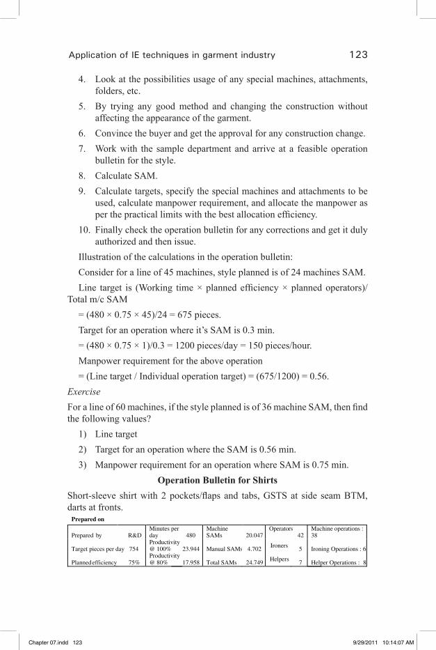
Application of IE techniques in garment industry 123
4. Look at the possibilities usage of any special machines, attachments, folders, etc.
5. By trying any good method and changing the construction without affecting the appearance of the garment.
6. Convince the buyer and get the approval for any construction change.7. Work with the sample department and arrive at a feasible operation
bulletin for the style.8. Calculate SAM.9. Calculate targets, specify the special machines and attachments to be
used, calculate manpower requirement, and allocate the manpower as per the practical limits with the best allocation efficiency.
10. Finally check the operation bulletin for any corrections and get it duly authorized and then issue.
Illustration of the calculations in the operation bulletin: Consider for a line of 45 machines, style planned is of 24 machines SAM.Line target is (Working time × planned efficiency × planned operators)/
Total m/c SAM= (480 × 0.75 × 45)/24 = 675 pieces.Target for an operation where it’s SAM is 0.3 min.= (480 × 0.75 × 1)/0.3 = 1200 pieces/day = 150 pieces/hour.Manpower requirement for the above operation = (Line target / Individual operation target) = (675/1200) = 0.56.
ExerciseFor a line of 60 machines, if the style planned is of 36 machine SAM, then find the following values?
1) Line target2) Target for an operation where the SAM is 0.56 min.3) Manpower requirement for an operation where SAM is 0.75 min.
Operation Bulletin for ShirtsShort-sleeve shirt with 2 pockets/flaps and tabs, GSTS at side seam BTM, darts at fronts.
Prepared on
Prepared by R&D Minutes per day 480
Machine SAMs 20.047
Operators 42
Machine operations : 38
Target pieces per day 754 Productivity @ 100% 23.944 Manual SAMs 4.702 Ironers 5 Ironing Operations : 6
Planned efficiency 75% Productivity @ 80% 17.958 Total SAMs 24.749 Helpers 7 Helper Operations : 8
Chapter 07.indd 123 9/29/2011 10:14:07 AM
�� �� �� �� ��
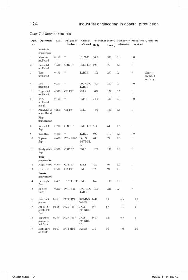
124 Industrial engineering in apparel production
Table 7.3 Operation bulletin
Opn. no.
Operation SAM PF/guides/ folders
Class of m/c used
Production @80% Manpower calculated
Manpower required
CommentsDaily Hourly
Neckband preparation
1 Mark on neckband
0.150 * CT M/C 2400 300 0.3 1.0
2 Run stitch neckband
0.600 ORD PF SNLS EC 600 75 1.3 1
3 Turn neckband
0.190 * TABLE 1895 237 0.4 * Spare from NB marking
4 Iron neckband
0.200 * IRONING TABLE
1800 225 0.4 1.0
5 Edge stitch neckband
0.350 CR 1/4’’ SNLS 1029 129 0.7 1
6 Trim neckband margin
0.150 * SNEC 2400 300 0.3 1.0
7 Attach label to neckband
0.250 CR 1/4’’ SNLS 1440 180 0.5 1
Flap preparation
8 Run stitch flaps
0.700 ORD PF SNLS EC 514 64 1.5 1
9 Turn flaps 0.400 * TABLE 900 113 0.8 1.0 10 Top stitch
flaps0.600 P728 1/16’’ DNLS
1/4’’ NDL GG
600 75 1.3 1
11 Ready stitch flaps
0.300 ORD PF SNLS 1200 150 0.6 1
Tabs preparation
12 Prepare tabs 0.500 ORD PF SNLS 720 90 1.0 1 13 Edge tabs 0.500 CR 1/4’’ SNLS 720 90 1.0 1 Fronts
preparation
14 Hem right front
0.415 1/16” CRPF SNLS 867 108 0.9 1
15 Iron left front
0.200 PATTERN IRONING TABLE
1800 225 0.4 *
16 Iron front placket
0.250 PATTERN IRONING TABLE
1440 180 0.5 1.0
17 Att & TS plkt to left front
0.515 P728 1/16’’ DNLS 1/4’’ NDL GG
699 87 1.1 1
18 Top stitch placket on left front
0.354 P727 1/16’’ DNLS 1/4’’ NDL GG
1017 127 0.7 1
19 Mark darts on fronts
0.500 PATTERN TABLE 720 90 1.0 1.0
Chapter 07.indd 124 9/29/2011 10:14:07 AM
�� �� �� �� ��
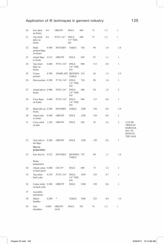
Application of IE techniques in garment industry 125
20 Sew darts on fronts
0.6 ORD PF SNLS 600 75 1.3 1
21 Top stitch darts on fronts
0.6 P728 1/16’’ DNLS 1/4’’ NDL GG
600 75 1.3 1
22 Mark pockets/flaps on fronts
0.500 PATTERN TABLE 720 90 1.0 1.0
23 Attach flaps to fronts
0.515 ORD PF SNLS 699 87 1.1 1
24 Top stitch flaps on fronts
0.400 P728 1/16’’ DNLS 1/4’’ NDL GG
900 113 0.8 1
25 Crease pockets
0.700 TEMPLATE IRONING TABLE
514 64 1.5 1.0
26 Hem pockets 0.500 P 718 1/16’’ DNLS 1/4’’ NDL GG
720 90 1.0 1
27 Attach pkt to fronts
0.900 P728 1/16’’ DNLS 1/4’’ NDL GG
400 50 1.9 2
28 Close flaps on fronts
0.400 P728 1/16’’ DNLS 1/4’’ NDL GG
900 113 0.8 1
29 Mark tabs on fronts
0.300 PATTERN TABLE 1200 150 0.6 1.0
30 Attach tabs to fronts
0.300 ORD PF SNLS 1200 150 0.6 1
31 Cross stitch on tabs
1.250 ORD PF SNLS 288 36 2.6 2 CAN BE TRIED IN BARTACK M/C TO REDUCE THE SAM
32 Tack tabs to the flaps
0.300 ORD PF SNLS 1200 150 0.6 1
Sleeves preparation
33 Iron sleeves 0.512 PATTERN IRONING TABLE
703 88 1.1 1.0
Backs preparation
34 Attach yokes to back panel
0.600 CR 3/8’’ SNLS 600 75 1.3 1
35 Top stitch back yoke
0.350 P728 1/16’’ DNLS 1/4’’ NDL GG
1029 129 0.7 1
36 Centre stitch on back yoke
0.300 ORD PF SNLS 1200 150 0.6 1
37 Assembly operations
38 Match bundles
0.200 * TABLE 1800 225 0.4 1.0
39 Join shoulders
0.609 ORD PF/A616
SNLS 591 74 1.3 1
Chapter 07.indd 125 9/29/2011 10:14:08 AM
�� �� �� �� ��

126 Industrial engineering in apparel production
40 Top stitch shoulders
0.340 P728 1/16’’ DNLS 1/4’’ NDL GG
1059 132 0.7 1
41 Centre stitch shoulders
0.300 CL 1/8’’ SNLS 1200 150 0.6 1
42 Attach neckband to body panel
0.650 ORD PF/A616
SNLS 554 69 1.4 1
43 Close neckband
0.750 CL 1/16’’ SNLS 480 60 1.6 2
44 Attach sleeves to armhole
0.900 CR 7/16’’ SNLS 400 50 1.9 2
45 Top stitch armhole
0.750 CR 3/8’’ SNLS 480 60 1.6 2
46 Hem sleeves
0.800 CL 1/16’’ SNLS 450 56 1.7 2
47 Attach w/c label to back panel
0.226 ORD PF/PATTERN
SNLS 1593 199 0.5 1
48 Close sides FOA
0.600 F335 FLDR 1/4’’ READY
FOA 600 75 1.3 1
49 Attach label to front plkt
0.423 ORD PF/PATTERN
SNLS 851 106 0.9 1
50 Hem bottom
0.700 6 MM BTM HEM FLDR
SNCS 514 64 1.5 1
51 Crease gusset pieces
0.450 PATTERN IRONING TABLE
800 100 0.9 1.0
52 Close gusset pieces on side seam bottom
0.900 CR 1/16’’ SNLS 400 50 1.9 2
52 24.749 56Buttoning section
AT 80% FOR 2000 PIECES PER DAY
53 Mark for button hole sew
0.400 Pattern TABLE 960 120 2.1 3
54 Button hole sew (7 nos.)
0.535 BH SEW M/C
718 90 2.8 3
55 Mark for button sew
0.400 Pattern TABLE 960 120 2.1 3
56 Button sew (8)
0.400 17L Buttons BTN SEW M/C
960 120 2.1 2
57 Mark for top snap buttons
0.250 Pattern TABLE 1536 192 1.3 1
58 Snap top button on tabs
0.200 Top snap button die set
SNAP BTN M/C
1920 240 1.0 1
Chapter 07.indd 126 9/29/2011 10:14:08 AM
�� �� �� �� ��

Application of IE techniques in garment industry 127
59 Mark for bottom snap buttons
0.250 PATTERN TABLE 1536 192 1.3 1
60 Snap bottom button on pockets
0.200 Bottom snap button die set
SNAP BTN M/C
1920 240 1.0 1
60 Machinery requirement for 1 line of 42 m/c each
SPL m/c requirement for 2,000 pieces per day
SNLS 29 BH sew m/c 3 SNLS EC 2 Button sew
m/c2
FOA 1 Snap button machines
2
SNCS 1 DNLS 1/4’’
NDL GG11
44
7.7 References
1. Seminar textbook (2000), sewing factory management technicians, Brother sewing technology center.
2. Seminar SCT (2010), Technical workplace skills for the garment industry, Sona School of garment and fashion technology.
Chapter 07.indd 127 9/29/2011 10:14:08 AM
�� �� �� �� ��
129
8Line balancing
8.1 Balancing
Effective planning (Efficient line balancing) Product analysis – Study of garment • Process analysis – Product flow chart • Capacity analysis – Time study, method study, •
no. of machines and operators, skill of operator.
8.1.1 Line balancing
A line is defined as a group of operators under the control of one production supervisor.
Balancing is the technique of maintaining the same level of inventory at each and every operation at any point of time to meet the production target and to produce garments of acceptable quality.It is a function of the work study office to provide management with information to help the efficient and productive running of the factory, and part of this information is the process known as line balancing.
Line balancing is a vital key in the efficient running of a line. The objective of the process is to ‘balance the workload’ of each operation to make sure that the flow of work is smooth, that no bottlenecks are created, and that the operators are able to work at peak performance throughout the day. This process is intended to reduce waiting time to a minimum, or in fact with the use of some work in progress to eliminate waiting time completely (Seminar SCT, 2010).
In operation breakdown we try to equalize the standard time.• But still there will be the difference in the standard time which leads to • work in progress.So, we try to set the flow through each operation to be similar as • possible.
Chapter 08.indd 129 9/29/2011 10:15:25 AM
�� �� �� �� ��

130 Industrial engineering in apparel production
Checking from time to time to see how things are going and then making • adjustments to even out the flow again. This process is called balancing.
8.1.2 Need for balancing
1. Keeping inventory cost low. 2. To enable the operator to work at the optimal pace. 3. To enable the supervisor to attend other problems. 4. To enable better production planning.5. Balancing production line results in on-time shipments, low cost, and
ensures reorders.
8.1.3 Goals for balancing
1. Meet production schedule 2. Avoid the waiting time3. Minimize over time4. Protect operator earnings
8.1.4 Rules for balancing
1. Have between 3 and 5 bundles of WIP at each operation 2. Solve the problem before they become larger 3. Meet production goals by keeping every operator working at maximum
capacity and make sure he has constant feeding to ensure his capacity is high.
8.1.5 How to balance the time?
1. Know work available at the start of the day 2. Plan transfer needed to compensate for any known absenteeism 3. Check attendance at the start of the day 4. Make additional assignments to compensate unexpected absentees 5. Make periodic checks during the day to check production
8.1.6 Points to be noted when making balancing
1. Meet production target by usage of a. Regular operators
Chapter 08.indd 130 9/29/2011 10:15:25 AM
�� �� �� �� ��
Line balancing 131
b. Utility operators c. Shuttle operators
2. Work flow should be constant throughout all operations 3. Avoid over time4. Determine human resource 5. Check absence daily6. Assign utility shuttle operators based on need7. Update daily production every two hours
8.1.7 Balanced production system
It is a production line where the line targets are achieved in all the operations with same amount of normal WIP at all workstations, at any point of time in the day.How to keep all operations producing at the same rate?
This is very difficult to achieve as the operator’s skill vary.• We should balance using utility operators to cover the gaps in • production.We should keep operators at the expected level of production, or higher • if possible.
How to start balancing the production line?Allocate operators based on the planned efficiency.• Determine the amount of WIP required to ensuring smooth flow.•
Why do we balance?1. To keep inventory cost low results in higher income.2. To keep the normal inventory levels let the operator work
consistently.3. To free the supervisors to concentrate on other areas.4. To keep the production cost low will increase the profits, which in turn
will make the facility more competitive.
8.2 Steps to balance the line
The method of line balancing can vary from factory to factory and depends on the garments manufactured; but at any instance, line balancing concerns itself with two distinct applications: “Opening the line” and “Operating the line”.
Chapter 08.indd 131 9/29/2011 10:15:25 AM
�� �� �� �� ��

132 Industrial engineering in apparel production
Calculation of labor requirements •
Operation breakdown •
– Opening the lineTheoretical operation balance •
Initial balance•
Balance control – Operating the line•
8.2.1 Calculation of labor requirement
Before a new style comes onto a line, it is necessary to establish the operation sequence, the time, the type of equipment and the attachments required to manufacture the order. Management must have this information before the commencement of the order, so that the line can be balanced and laid out in such a way as to maximize productivity.
There are two methods which can be used to set up a line:Method 1
Calculate how many operators will be necessary to achieve a given production rate per hour.Method 2
Calculate how many garments can be produced by a given number of operators.
One should know the total: work content of garment, standard time, estimated production per day, efficiency of operator, pieces per machine = 480 min/SAM.
Labor required = Estimated production per day / pieces per machine
8.2.2 Operation breakdown
Using either technique, there is certain information required before commencing the calculations:
1. The number of operators in the line2. Sequential list of operations by method study 3. The standard minute values for each operation4. Output required form a given group of operatorsWe require the following information
Chapter 08.indd 132 9/29/2011 10:15:25 AM
�� �� �� �� ��

Line balancing 133
The size of the groupAn operation sequenceThe standard time for each • operationThe total standard time for the garmentType of machineMachine attachments• Process name/code•
Work aid• s
8.2.3 Operation breakdown
Table 8.1 shows the operation break down for shirts assembly sections with machinery and SAM details.Table 8.1 Operation breakdown
S. no. Operation Machine ST in seconds1 Shoulder attach SNLS 1202 Shoulder top stitch DNLS 603 Collar attach SNLS 1204 Collar finish SNLS 2105 Sleeve attach SNLS 1006 Sleeve over lock 5O/L 607 Sleeve top stitch DNLS 608 Side seam 5O/L 609 Cuff attach / finish SNLS 24010 Bottom hem SNLS 100
8.2.4 Theoretical operation balance
Elements are grouped together as shown in Table 8.2 to match the number of people selected in the calculation of the labor requirements (Seminar SCT, 2010).Table 8.2 Theoretical operation balance
S. no. Operation Machine ST (seconds)1 Shoulder attach SNLS 1202 SHLDR T/S/SLVT/S SNLS 1203 Collar attach SNLS 1204 Collar Finish SNLS 1055 Collar finish SNLS 1056 Sleeve O/L/side
seam5O/L 120
7 Cuff attach SNLS 120
Chapter 08.indd 133 9/29/2011 10:15:25 AM
�� �� �� �� ��
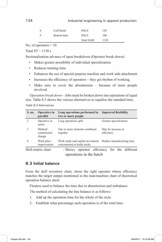
134 Industrial engineering in apparel production
8 Cuff finish SNLS 1209 Bottom hem SNLS 100
Total SAM 1130
No. of operators = 10 Total ST = 1130 s Sectionalisation advance of open breakdown (Operator break down):
Makes greater possibility of individual specialization • Reduces training time• Enhances the use of special purpose machine and work aids attachment • Increases the efficiency of operators – they get rhythm of working. • Make easy to cover the absenteeism – because of more people • involved.
Operation break down – Jobs must be broken down into operations of equal size. Table 8.3 shows the various alternatives to equalize the standard time.Table 8.3 Alternatives
S. no. Operative in parallel
Long operations performed by two or more people
Improved flexibility
2 Operative in series
Long operations split Greater specialization
3 Method/construction change
One or more elements combined together
May be increase in efficiency
4 Work place improvement
Work study and capital investment concentrated at bottle necks
Reduce manufacturing time
Skill matrix chart – Shows operator efficiency for the different operations in the batch
8.3 Initial balance
From the skill inventory chart, chose the right operator whose efficiency matches the target output mentioned in the man/machine chart of theoretical operation balance sheet.
Floaters used to balance the time due to absenteeism and imbalance.The method of calculating the line balance is as follows:1. Add up the operation time for the whole of the style.2. Establish what percentage each operation is of the total time.
Chapter 08.indd 134 9/29/2011 10:15:26 AM
�� �� �� �� ��

Line balancing 135
3. Work out what the theoretical balance is by using each operation’s percentage of the total number of operators on the line.
4. Round the theoretical balance to the nearest half an operators on the line.
5. List the type of equipments required for each operation at the side of your rounded figure.
6. Where you have “half” operators, combine similar equipment to get “full” operators.
7. If you have an odd “half” operator, this obviously will be rounded up (The operator could be used to help balance the line in situations such as absenteeism, machine troubles, etc.).
8. You can now calculate the number of garments that would be produced per hour on each operation by multiplying the number of operators by 60 minutes and dividing by the total minutes for the style. This will give you the theoretical number of garments that will be produced through each operation.
9. You may now wish to use your knowledge of the skill levels of each operator to establish which operators will give you the best possible output per operation.
This can be done on a computer using Excel.Op no. Description M/C Time in
(min.)%
1 Join shoulders S/S 0.36 1.5
2 Set sleeves S/S 0.83 3.5
3 Close sides S/S 1.02 4.3
4 Att. collars S/N 0.86 3.6
5 T/S collar S/N 0.73 3.2
Now, to calculate the number of operators required for each operation, we need the number of operators in the group.
In the following example, we have 10 operators on the section.Therefore,Op no Description M/C Time % No of ops 10
1 Join shoulders S/S 0.36
2 Set sleeves S/S 0.83
3 Close sides S/S 1.02
4 Att. collars S/N 0.86
5 T/S collar S/N 0.73
Chapter 08.indd 135 9/29/2011 10:15:26 AM
�� �� �� �� ��
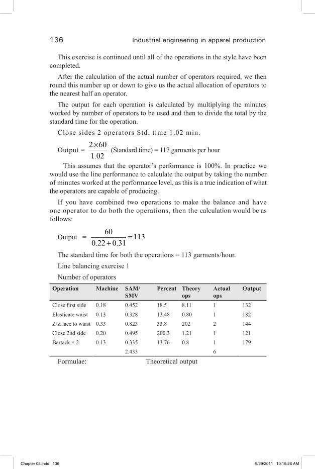
136 Industrial engineering in apparel production
This exercise is continued until all of the operations in the style have been completed.
After the calculation of the actual number of operators required, we then round this number up or down to give us the actual allocation of operators to the nearest half an operator.
The output for each operation is calculated by multiplying the minutes worked by number of operators to be used and then to divide the total by the standard time for the operation.
Close sides 2 operators Std. time 1.02 min.
Output = 2 601.02×
(Standard time) = 117 garments per hour
This assumes that the operator’s performance is 100%. In practice we would use the line performance to calculate the output by taking the number of minutes worked at the performance level, as this is a true indication of what the operators are capable of producing.
If you have combined two operations to make the balance and have one operator to do both the operations, then the calculation would be as follows:
Output = 60 113
0.22 0.31=
+The standard time for both the operations = 113 garments/hour.Line balancing exercise 1Number of operators
Operation Machine SAM/SMV
Percent Theory ops
Actual ops
Output
Close first side 0.18 0.452 18.5 8.11 1 132
Elasticate waist 0.13 0.328 13.48 0.80 1 182Z/Z lace to waist 0.33 0.823 33.8 202 2 144Close 2nd side 0.20 0.495 200.3 1.21 1 121Bartack × 2 0.13 0.335 13.76 0.8 1 179
2.433 6
Formulae: Theoretical output
Chapter 08.indd 136 9/29/2011 10:15:26 AM
�� �� �� �� ��
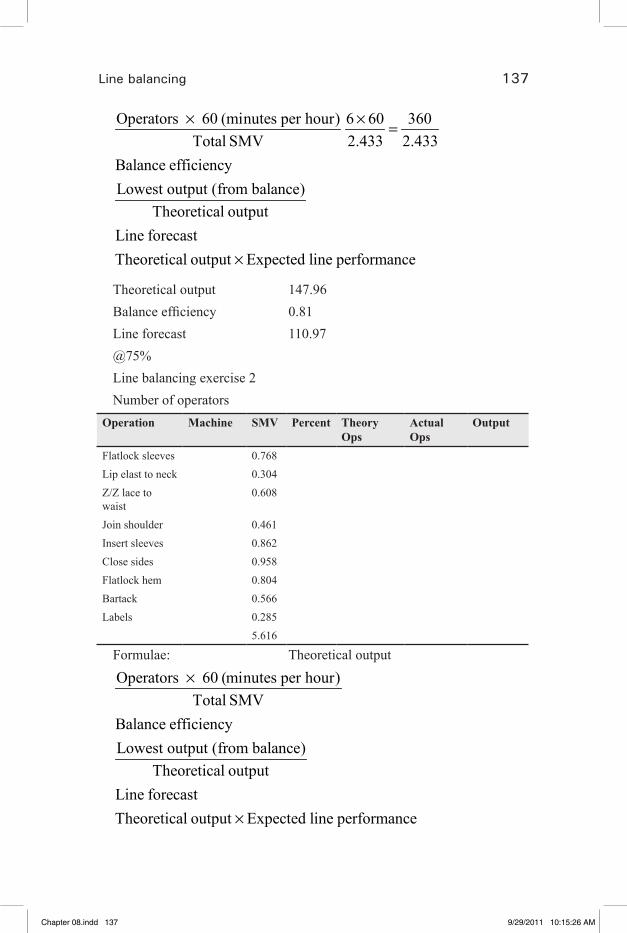
Line balancing 137
Operators 60 (minutes per hour) 6 60 360Total SMV 2.433 2.433
Balance efficiencyLowest output (from balance)
Theoretical outputLine forecastTheoretical output Expected line performance
× × =
×
Theoretical output 147.96Balance efficiency 0.81Line forecast 110.97@75%Line balancing exercise 2Number of operators
Operation Machine SMV Percent Theory Ops
Actual Ops
Output
Flatlock sleeves 0.768Lip elast to neck 0.304Z/Z lace to waist
0.608
Join shoulder 0.461Insert sleeves 0.862Close sides 0.958Flatlock hem 0.804Bartack 0.566Labels 0.285
5.616
Formulae: Theoretical output
Operators 60 (minutes per hour)Total SMV
Balance efficiencyLowest output (from balance)
Theoretical outputLine forecastTheoretical output Expected line performance
×
×
Chapter 08.indd 137 9/29/2011 10:15:26 AM
�� �� �� �� ��
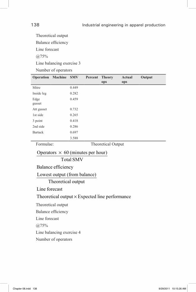
138 Industrial engineering in apparel production
Theoretical outputBalance efficiencyLine forecast@75%Line balancing exercise 3Number of operators
Operation Machine SMV Percent Theory ops
Actual ops
Output
Mitre 0.449Inside leg 0.282Edge gusset
0.459
Att gusset 0.7321st side 0.2653 point 0.4182nd side 0.286Bartack 0.697
3.588
Formulae: Theoretical Output
Operators 60 (minutes per hour)Total SMV
Balance efficiencyLowest output (from balance)
Theoretical outputLine forecastTheoretical output Expected line performance
×
×Theoretical outputBalance efficiencyLine forecast@75%Line balancing exercise 4Number of operators
Chapter 08.indd 138 9/29/2011 10:15:26 AM
�� �� �� �� ��

Line balancing 139
Operation Machine SMV Percent Theory ops Actual ops
Output
Join shoulders Safety 0.54Fit collar Flat 0.85Close collar Flat 0.8Fit sleeves Safety 0.84Close sides Safety 0.76Hem button Flat 0.74Hem sleeves Flat 0.83Button hole front B/Hole 0.71Button sew B/Sew 0.69
Formulae: Theoretical output
Operators 60 (minutes per hour)Total SMV
Balance efficiencyLowest output (from balance)
Theoretical outputLine forecastTheoretical output Expected line performance
×
=
=×
Theoretical outputBalance efficiencyLine forecast@75%Line balancing exercise 5Number of operators
Operation Machine SMV Percent Theory ops Actual ops Output
Join shoulders Safety 0.54Fit collar Flat 0.85Close collar Flat 0.8Fit sleeves Safety 0.84Close sides Safety 0.76Hem button Flat 0.74Hem sleeves Flat 0.83
Chapter 08.indd 139 9/29/2011 10:15:26 AM
�� �� �� �� ��
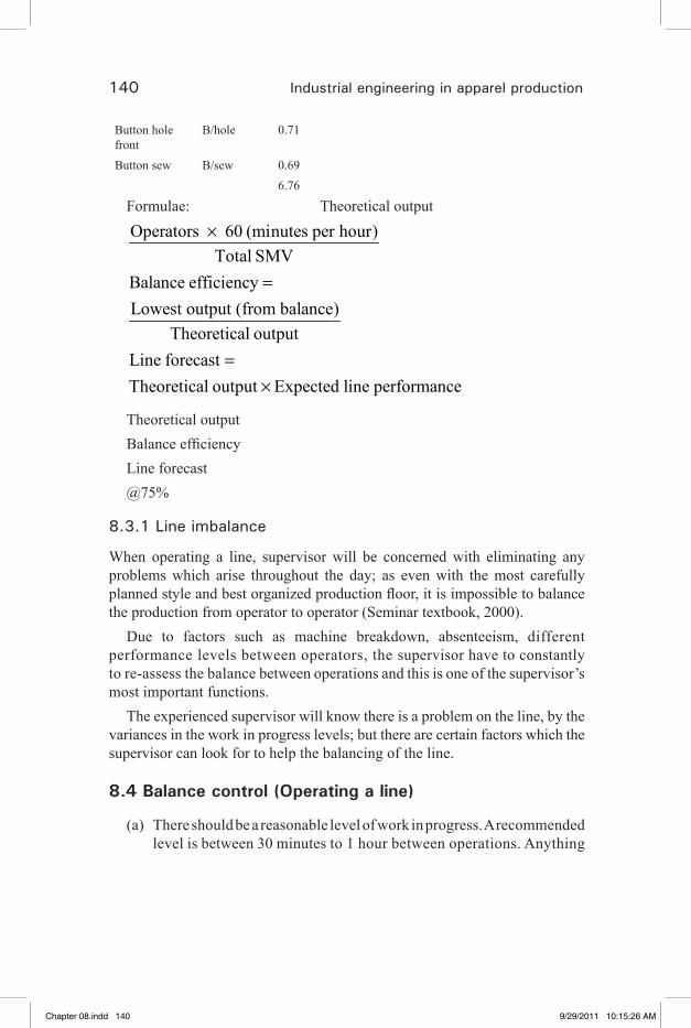
140 Industrial engineering in apparel production
Button hole front
B/hole 0.71
Button sew B/sew 0.696.76
Formulae: Theoretical output
Operators 60 (minutes per hour)Total SMV
Balance efficiencyLowest output (from balance)
Theoretical outputLine forecastTheoretical output Expected line performance
×
=
=×
Theoretical output Balance efficiency Line forecast @75%
8.3.1 Line imbalance
When operating a line, supervisor will be concerned with eliminating any problems which arise throughout the day; as even with the most carefully planned style and best organized production floor, it is impossible to balance the production from operator to operator (Seminar textbook, 2000).
Due to factors such as machine breakdown, absenteeism, different performance levels between operators, the supervisor have to constantly to re-assess the balance between operations and this is one of the supervisor’s most important functions.
The experienced supervisor will know there is a problem on the line, by the variances in the work in progress levels; but there are certain factors which the supervisor can look for to help the balancing of the line.
8.4 Balance control (Operating a line)
(a) There should be a reasonable level of work in progress. A recommended level is between 30 minutes to 1 hour between operations. Anything
Chapter 08.indd 140 9/29/2011 10:15:26 AM
�� �� �� �� ��
Line balancing 141
below 30 minutes will not give the supervisor sufficient time to react to a breakdown. Anything above 1 hour’s supply is unnecessary.
(b) Work in progress should always be kept in good order and full view.(c) Have a number of additional machinists trained on many
operations so that they can be used, wherever necessary, to cover for absenteeism. Therefore if absenteeism is 5%, a squad of skilled operator would be required to cover this amount.
(d) Space should be made available within the line for spare machines in case of a breakdown.
(e) Ensure that the mechanics keep the machines regularly serviced.
(f) If a bottle-neck keeps occurring at a particular place in the line, improve the method to eliminate the bottle neck (It is most important to establish where this point is on the line.
(g) Supervisors must know the capabilities and skills of the operators under their control.
(h) Supervisors must learn that the amount of work waiting for each operation will increase or decrease over a period of time, and must plan when to take appropriate action. The supervisor should have in mind a minimum and maximum number of bundles that should be at each operation, and what action to take if the level drops or rises.
(i) Supervision could carry out ‘balancing duty’ regularly at 2-hour intervals, checking every operation on the line to ensure that the work-in-progress level is within the correct limits.
(j) Balancing duties should be carried out on time irrespective of what else the supervisor is doing.
(k) The supervisor should be able to make up his/her mind about what to do if the levels are not correct, and not have to wait for the manager to make the decision for him/her.
8.4.1 Using the daily production sheet in line balancing
The use of a daily production sheet will also assist the supervisor in the balancing of the line, as it shows where problems exist due to the difference in production levels between operations.
The output of each operation and each operator is recorded hourly, thus giving hourly production figures throughout the day.
Chapter 08.indd 141 9/29/2011 10:15:26 AM
�� �� �� �� ��

142 Industrial engineering in apparel production
If the production rate drops below the target, the supervisor can identify the problem and help to redress the balance. The advantages of using the production sheet are that the supervisor can address any problems hourly as they occur. This, done in conjunction with the balancing form, will stop the situation getting out of hand.
8.4.2 Forecasting the days production when absenteeism occurs
1. Take the total time allowed for the style on the line.2. Divide the total time allowed by the efficiency currently being
achieved,E.g., total time for garment is 20 minutes; Current efficiency is, say, 80%.
20 (80%) 25 minutes80
=
(You are therefore producing the garment in 25 minutes.)
3. Your normal number of operators is 30, therefore your hourly target should be
30 60 72 garments per hour25× =
4. If your absenteeism is 5 operators then anticipated output, provided that you can successfully rebalance your line, should be
25 60 60 garments per hour25× =
8.5 Efficiency
Efficiency is another way of expressing productivity, although efficiency figures are more useful and meaningful. Efficiency figures tell us how we perform against a target which has been set by scientific means.
As the target is expressed as a time per garment or a required level of production, the efficiency is quite easy to calculate.
Targets are normally set at a performance level of 100%, and therefore if an operator reaches his/her target production, then his/her efficiency would be 100%.
Chapter 08.indd 142 9/29/2011 10:15:27 AM
�� �� �� �� ��
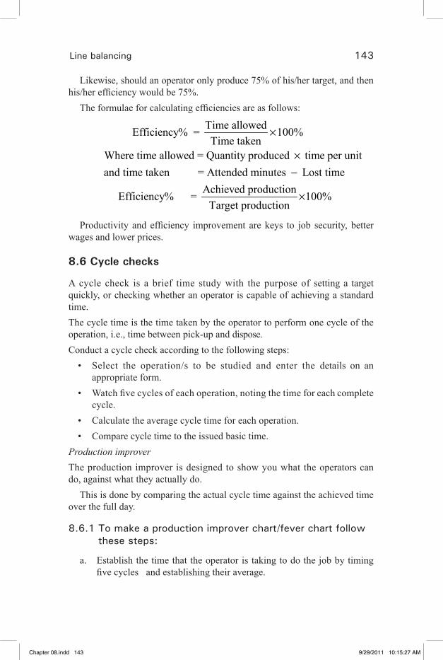
Line balancing 143
Likewise, should an operator only produce 75% of his/her target, and then his/her efficiency would be 75%.
The formulae for calculating efficiencies are as follows:
Time allowed Efficiency% = 100%Time taken
Where time allowed = Quantity produced time per unitand time taken = Attended minutes Lost time
Achieved product Efficiency% =
×
×−
ion 100%Target production
×
Productivity and efficiency improvement are keys to job security, better wages and lower prices.
8.6 Cycle checks
A cycle check is a brief time study with the purpose of setting a target quickly, or checking whether an operator is capable of achieving a standard time.The cycle time is the time taken by the operator to perform one cycle of the operation, i.e., time between pick-up and dispose.Conduct a cycle check according to the following steps:
Select the operation/s to be studied and enter the details on an • appropriate form.Watch five cycles of each operation, noting the time for each complete • cycle.Calculate the average cycle time for each operation.• Compare cycle time to the issued basic time.•
Production improverThe production improver is designed to show you what the operators can do, against what they actually do.
This is done by comparing the actual cycle time against the achieved time over the full day.
8.6.1 To make a production improver chart/fever chart follow these steps:
a. Establish the time that the operator is taking to do the job by timing five cycles and establishing their average.
Chapter 08.indd 143 9/29/2011 10:15:27 AM
�� �� �� �� ��
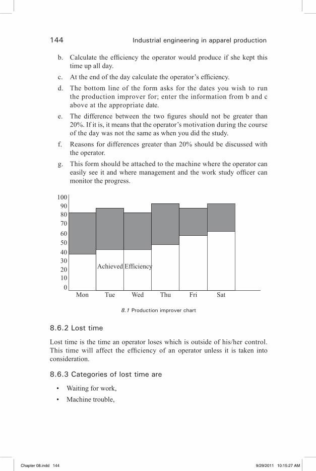
144 Industrial engineering in apparel production
b. Calculate the efficiency the operator would produce if she kept this time up all day.
c. At the end of the day calculate the operator’s efficiency.d. The bottom line of the form asks for the dates you wish to run
the production improver for; enter the information from b and c above at the appropriate date.
e. The difference between the two figures should not be greater than 20%. If it is, it means that the operator’s motivation during the course of the day was not the same as when you did the study.
f. Reasons for differences greater than 20% should be discussed with the operator.
g. This form should be attached to the machine where the operator can easily see it and where management and the work study officer can monitor the progress.
Mon
1009080706050403020100
Tue Wed Thu
Achieved Efficiency
Fri Sat
8.1 Production improver chart
8.6.2 Lost time
Lost time is the time an operator loses which is outside of his/her control. This time will affect the efficiency of an operator unless it is taken into consideration.
8.6.3 Categories of lost time are
Waiting for work,• Machine trouble,•
Chapter 08.indd 144 9/29/2011 10:15:27 AM
�� �� �� �� ��
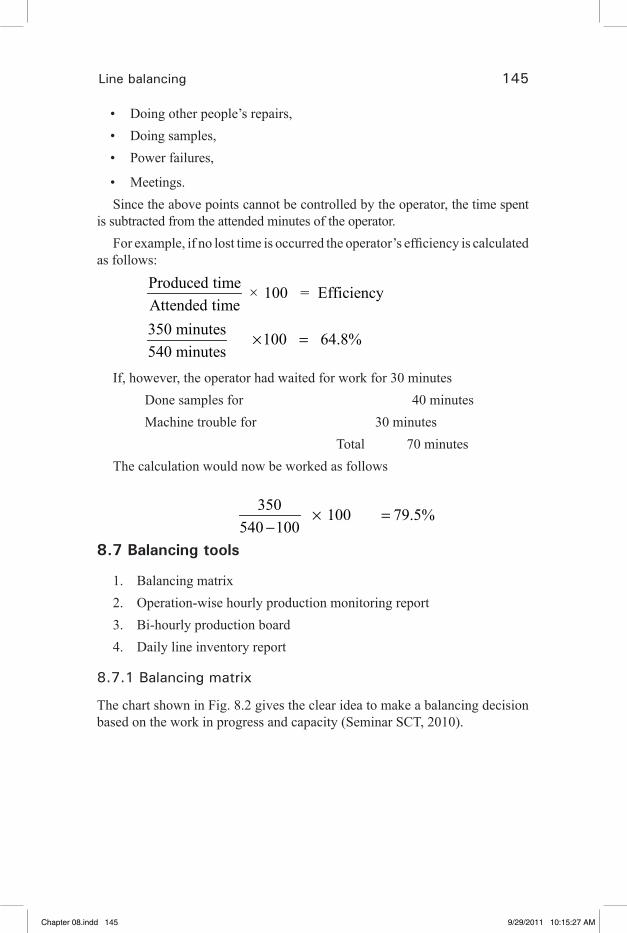
Line balancing 145
Doing other people’s repairs,• Doing samples,• Power failures,•
Meetings.• Since the above points cannot be controlled by the operator, the time spent
is subtracted from the attended minutes of the operator.For example, if no lost time is occurred the operator’s efficiency is calculated
as follows:
Produced time × 100 = EfficiencyAttended time350 minutes 100 64.8%540 minutes
× =
If, however, the operator had waited for work for 30 minutes Done samples for 40 minutes Machine trouble for 30 minutes Total 70 minutesThe calculation would now be worked as follows
350 100 79.5%
540 100× =
−8.7 Balancing tools
1. Balancing matrix2. Operation-wise hourly production monitoring report3. Bi-hourly production board4. Daily line inventory report
8.7.1 Balancing matrix
The chart shown in Fig. 8.2 gives the clear idea to make a balancing decision based on the work in progress and capacity (Seminar SCT, 2010).
Chapter 08.indd 145 9/29/2011 10:15:27 AM
�� �� �� �� ��
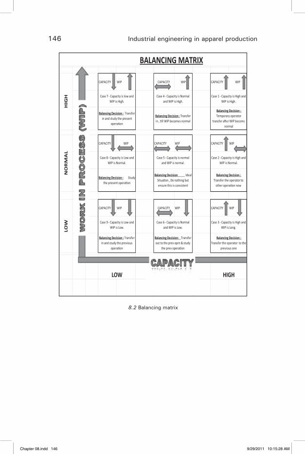
146 Industrial engineering in apparel production
CAPACITY WIP CAPACITY WIP CAPACITY WIP
CAPACITY WIP CAPACITY WIP CAPACITY WIP
CAPACITY WIP CAPACITY WIP CAPACITY WIP
Case 6 - Capacity is Normal and WIP is Low.
Case 3 - Capacity is High and WIP is Long.
Balancing Decision : Transfer in and study the previous
opera�on
Balancing Decision: Transfer out to the prev oprn & study
the prev opera�on
Balancing Decision : Transfer the operator to the
previous one
LOW NORMAL HIGH
NO
RM
AL
Case 8 - Capacity is Low and WIP is Normal.
Case 5 - Capacity is normal and WIP is normal.
Case 2 - Capacity is High and WIP is Normal.
Balancing Decision : Study the present opera�on
Balancing Decision Ideal Situa�on , Do nothing but ensure this is consistent
Balancing Decision : Transfer the operator to
other opera�on now
LOW Case 9 - Capacity is Low and
WIP is Low.
BALANCING MATRIXH
IGH Case 7 - Capacity is low and
WIP is High.Case 4 - Capacity is Normal
and WIP is High.Case 1 - Capacity is High and
WIP is High.
Balancing Decision : Transfer in and study the present
opera�on
Balancing Decision : Transfer in , �ll WIP becomes normal
Balancing Decision : Temporary operator
transfer a�er WIP becoms normal
8.2 Balancing matrix
Chapter 08.indd 146 9/29/2011 10:15:28 AM
�� �� �� �� ��
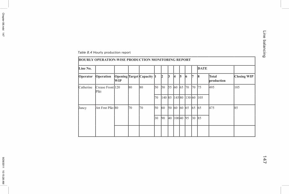
Line balancing 147
HOURLY OPERATION-WISE PRODUCTION MONITORING REPORT
Line No. DATE
Operator Operation Opening WIP
Target Capacity 1 2 3 4 5 6 7 8 Total production
Closing WIP
Catherine Crease Front Plkt
120 80 80 50 50 55 60 65 70 70 75 495 105
70 140 85 145 80 130 60 105
Jancy Att Frnt Plkt 80 70 70 50 60 50 60 60 65 65 65 475 85
30 90 40 100 40 95 30 85
Table 8.4 Hourly production report
Chapter 08.indd 147
9/29/2011 10:15:28 AM
����������
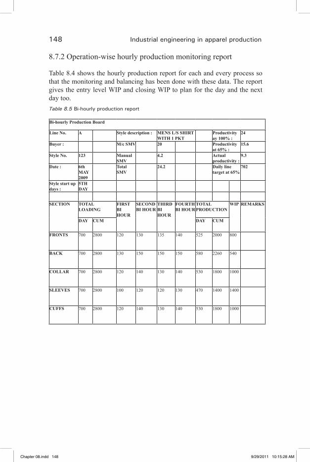
148 Industrial engineering in apparel production
8.7.2 Operation-wise hourly production monitoring report
Table 8.4 shows the hourly production report for each and every process so that the monitoring and balancing has been done with these data. The report gives the entry level WIP and closing WIP to plan for the day and the next day too.Table 8.5 Bi-hourly production report
Bi-hourly Production Board
Line No. A Style description : MENS L/S SHIRT WITH 1 PKT
Productivity ay 100% :
24
Buyer : M/c SMV 20 Productivity at 65% :
15.6
Style No. 123 Manual SMV
4.2 Actual productivity :
9.3
Date : 6th MAY 2009
Total SMV
24.2 Daily line target at 65%
702
Style start up days :
5TH DAY
SECTION TOTAL LOADING
FIRST BI HOUR
SECOND BI HOUR
THIRD BI HOUR
FOURTH BI HOUR
TOTAL PRODUCTION
WIP REMARKS
DAY CUM DAY CUM
FRONTS 700 2800 120 130 135 140 525 2000 800
BACK 700 2800 130 150 150 150 580 2260 540
COLLAR 700 2800 120 140 130 140 530 1800 1000
SLEEVES 700 2800 100 120 120 130 470 1400 1400
CUFFS 700 2800 120 140 130 140 530 1800 1000
Chapter 08.indd 148 9/29/2011 10:15:28 AM
�� �� �� �� ��

Line balancing 149
MATCH BUNDLES
470 1400 120 120 120 120 480 1400 0
ASSEMBLY 480 1400 100 100 110 110 420 1000 400
TOTAL 700 2800 100 100 110 110 420 1000 1800
ON ROLL
PRESENT ABSENT DAY LINE EFFICIENCY
38.9%
NUMBER OF OPERATORS
50 45 5 STYLE AVREAGE EFFICIENCY
20.83%
NUMBER OF IRONERS
5 5 0
NUMBER OF HELPERS
17 15 2
8.7.3 Bi-hourly production board
Table 8.5 shows the bi-hourly production report where the production details of each and every section noted for every 2 hours. This is vital information to conduct bi-hourly meeting with all the department staffs to ensure the line in balance. This report has the loading details and WIP details to make the balancing decision.
Chapter 08.indd 149 9/29/2011 10:15:28 AM
�� �� �� �� ��
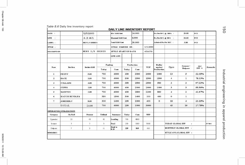
150
Industrial engineering in apparel productionTable 8.6 Daily line inventory report
Chapter 08.indd 150
9/29/2011 10:15:28 AM
����������
Line balancing 151
8.7.4 Daily line inventory report
Table 8.6 shows the daily line inventory report which gives the overall performance of the line for the day. The feeding and production details give the remaining inventory in the line for each and every section and also the efficiency of the sections recorded. These details used for the next day planning and balancing.
8.8 References
1. Seminar Textbook (2000). Sewing factory management technicians, Brother Sewing Technology Center.
2. Seminar SCT (2010). Technical workplace skills for the garment industry, Sona School of Garment and Fashion Technology.
Chapter 08.indd 151 9/29/2011 10:15:28 AM
�� �� �� �� ��
153
9Scientific method of training
9.1 SMT (Scientific method of training)
SMT is the methodology for training operator in a structured way.The main principles which are applied in SMT to meet the training needs
of modern industry are summarized in the sections below.
9.1.1 Job analysis
Detailed studies are required for each job for which an SMT training course is set up, ranging from the overall arrangement and organization of the work to the specific techniques and skills involved in individual job elements.
The basic skills required in a job should be developed separately to the level and pace of the experienced operators at the beginning of training, and combined progressively until all job skills are being performed correctly. The work assignment is then extended as performance permits until a full work load is being satisfactorily carried out over an entire working day.
9.1.2 Systematic skill, stamina and knowledge development
The training exercises are designed in such a way to develop basic skills. Once the basic skills are achieved, the next step is the performance of small elements of the actual operation. The exercise for this phase of development are called “Job Exercise and Parts Exercise.”
The exercises are then extended and combined progressively until the whole job is being performed—first for the short period and finally on a full job assignment. These exercises are called “stamina – build up exercises.” (Seminar SCT, 2010)
9.1.3 Established goals and targets
It is necessary to have a specific goal to aim at throughout the training period. Targets are set for all exercises and performance is measured against these
Chapter 09.indd 153 9/29/2011 10:16:22 AM
�� �� �� �� ��

154 Industrial engineering in apparel production
targets. Progress to longer and more difficult exercises is dependent upon achievement of targets on simpler ones. Targets are set at the level expected of the experienced worker.
9.1.4 Defined quality specifications
It is essential that a clear understanding of the quality requirements of the job be developed, along with a systematic training in skill and stamina. As a part of the job knowledge training, the quality requirements must be defined in terms the operator can work with and understand. The quality specifications are prepared in terms applicable to the job, including where possible actual examples showing limits of acceptability, the standard at which to aim and examples of defects and errors.
9.1.5 Establishment of a training centre
The most effective and rapid learning is achieved in an area separate from the main work area. The training centre should be equipped to facilitate basic skills and knowledge training away from the distraction of the actual working area. In the training centre, work is oriented to build an atmosphere for learning, and the prime objective is the motivation of people to acquire job ability.The use of “mock-up” must be utilized as much as possible in the training centre.
9.1.6 Selection and placement
It is very important to select right person for the right job. There is no point to train operators who do not have necessary aptitude for the job. In a market where there is shortage of labor, it is not always possible to select sufficient operators of the desired caliber. What is essential is that once selected, they should be placed on the job for which they are most suited. The process of selection and placement does not end in the personnel office, it must be carried on in the training program, particularly during the early stages. (Jacob solinger, 1980)
9.1.7 Aims of SMT
The scientific method of training has been developed to provide the easiest, most efficient and most rapid method of training industrial workers.The main aims of SMT are as follows:
9.1.8 Ease of learning
Learning any new job is difficult and requires hard work, concentrated attention and a will to learn. SMT helps to make learning less difficult by training a new
Chapter 09.indd 154 9/29/2011 10:16:22 AM
�� �� �� �� ��

Scientific method of training 155
worker in each aspect of the job, one stage at a time and by providing constant help and guidance throughout the learning period.
9.1.9 Efficient learning
This is the most efficient method of training. Only correct methods, correct pace (whenever practical), coordination, the correct quality and safety procedures are used. In addition, each trainee is made to follow the program suited to his own ability, so that he can concentrate his attention on those parts of the job which he needs to practice the most.
9.1.10 Rapid learning
With SMT new workers are trained to achieve high production and good quality in only one-third to one-half of the time normally taken. This streamlined learning process helps the trainee to achieve a high level of productivity much sooner than he would otherwise have done.
9.1.11 Retraining
SMT is also used to help the experienced operators who are having difficulty with the job or a part of the job. The retraining helps to improve the quality and quantity of work.
9.1.12 Cross-training
When an operator achieves the target and quality in his/her regular operation, he/she can be trained for the preceding or the succeeding operation or any other similar operation. The SMT approach eases the transition from the old job to new job and helps the operator make a full contribution to production sooner.
9.1.13 Results of SMT
More successful learners• Reduced labor turnover• Reduced cost• Improved quality•
9.2 Methodology behind SMT
The success of SMT is based on the following methodology which have been found effective.
Chapter 09.indd 155 9/29/2011 10:16:22 AM
�� �� �� �� ��
156 Industrial engineering in apparel production
Operation analysis – Each operation and procedure is analyzed in detail in order to determine the best methods, to see and to discover the skills required in these methods.
Separate training course – A special training course is designed for each operation to enable the trainee to learn each aspect of the job separately and develop through progressive stages of training.
Skill development – Special exercises are designed to develop the skills required in the job, individually and progressively.
Breakdown into parts – The job is broken down into parts which the trainee learns separately, and then gradually combines them when she becomes proficient.
Spaced learning – The trainee’s activities are programmed in order to provide change of activity and to maintain a high degree of concentration.
Rhythm and pace – The trainee learns each part and skill of the job at 100% pace right from the start.
Stamina buildup – At first the trainee concentrates on skill, methods and pace, and practices for only short periods of time. Only when she has developed the necessary skill does she start to develop stamina by practicing progressively longer tasks.
Goals and targets – Targets are set for every stage of training. This enables each trainee to know how she is progressing and gives her a sense of achievement when she attains them.
Measurements and controls – The trainee’s progress is measured carefully at every stage, so that both the trainee and the instructor have an intimate knowledge of progress.
Individual program – Each trainee advances according to her own ability and spends most of her time practicing those aspects of the job in which she is weak.
Training centre – Basic skill and knowledge training is carried out in an area separate from production, where trainees can learn in an atmosphere suitable to learn without any disturbance.
Quality specification – Detailed quality specifications are worked out for each operation as a basis for training in correct quality.
Participation – The trainees are encouraged to develop a sense of responsibility and pride in their own progress by participating actively in the administration and planning of their own training activities.
Chapter 09.indd 156 9/29/2011 10:16:22 AM
�� �� �� �� ��
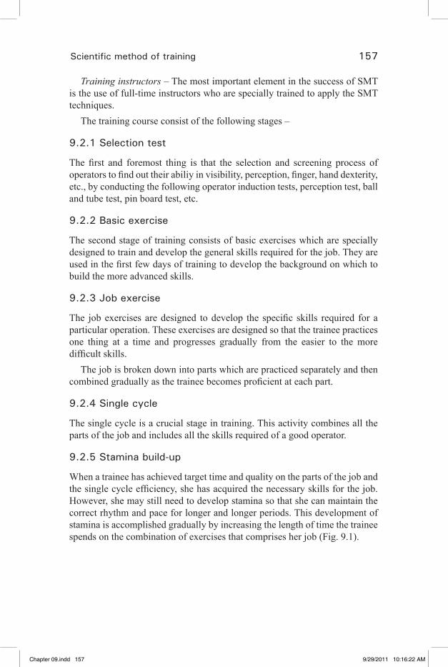
Scientific method of training 157
Training instructors – The most important element in the success of SMT is the use of full-time instructors who are specially trained to apply the SMT techniques.
The training course consist of the following stages –
9.2.1 Selection test
The first and foremost thing is that the selection and screening process of operators to find out their abiliy in visibility, perception, finger, hand dexterity, etc., by conducting the following operator induction tests, perception test, ball and tube test, pin board test, etc.
9.2.2 Basic exercise
The second stage of training consists of basic exercises which are specially designed to train and develop the general skills required for the job. They are used in the first few days of training to develop the background on which to build the more advanced skills.
9.2.3 Job exercise
The job exercises are designed to develop the specific skills required for a particular operation. These exercises are designed so that the trainee practices one thing at a time and progresses gradually from the easier to the more difficult skills.
The job is broken down into parts which are practiced separately and then combined gradually as the trainee becomes proficient at each part.
9.2.4 Single cycle
The single cycle is a crucial stage in training. This activity combines all the parts of the job and includes all the skills required of a good operator.
9.2.5 Stamina build-up
When a trainee has achieved target time and quality on the parts of the job and the single cycle efficiency, she has acquired the necessary skills for the job. However, she may still need to develop stamina so that she can maintain the correct rhythm and pace for longer and longer periods. This development of stamina is accomplished gradually by increasing the length of time the trainee spends on the combination of exercises that comprises her job (Fig. 9.1).
Chapter 09.indd 157 9/29/2011 10:16:22 AM
�� �� �� �� ��
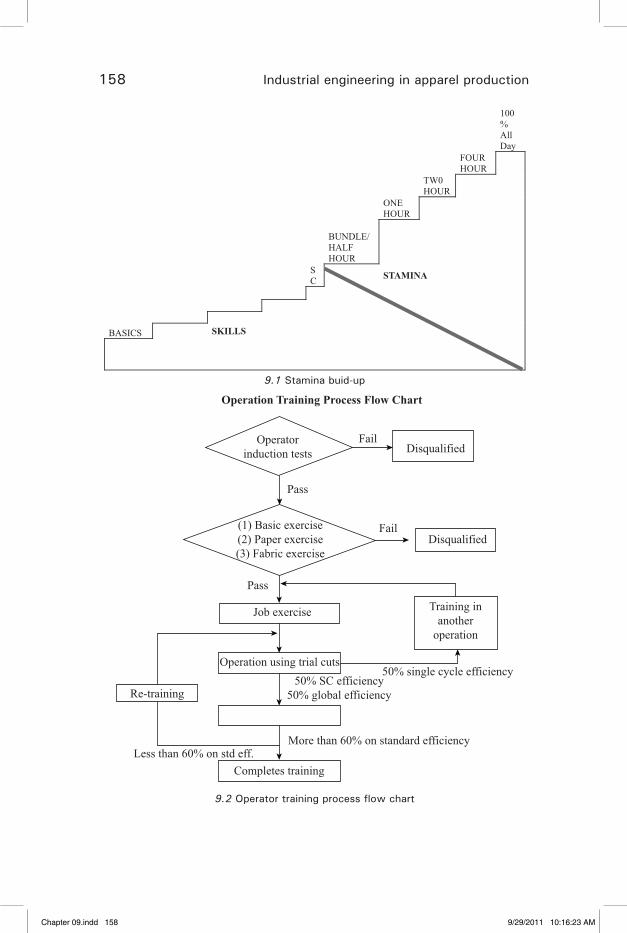
158 Industrial engineering in apparel production
100%All Day
FOUR HOUR
TW0HOUR
ONE HOUR
BUNDLE/ HALF HOUR
SC STAMINA
BASICS SKILLS
9.1 Stamina buid-up
Operatorinduction tests Disqualified
Fail
Operation Training Process Flow Chart
Fail
Pass
Pass
Job exercise
Operation using trial cuts
Re-training
Completes trainingLess than 60% on std eff.
More than 60% on standard efficiency
50% single cycle efficiency50% SC efficiency
50% global efficiency
Training inanother
operation
(1) Basic exercise(2) Paper exercise(3) Fabric exercise
Disqualified
9.2 Operator training process flow chart
Chapter 09.indd 158 9/29/2011 10:16:23 AM
�� �� �� �� ��
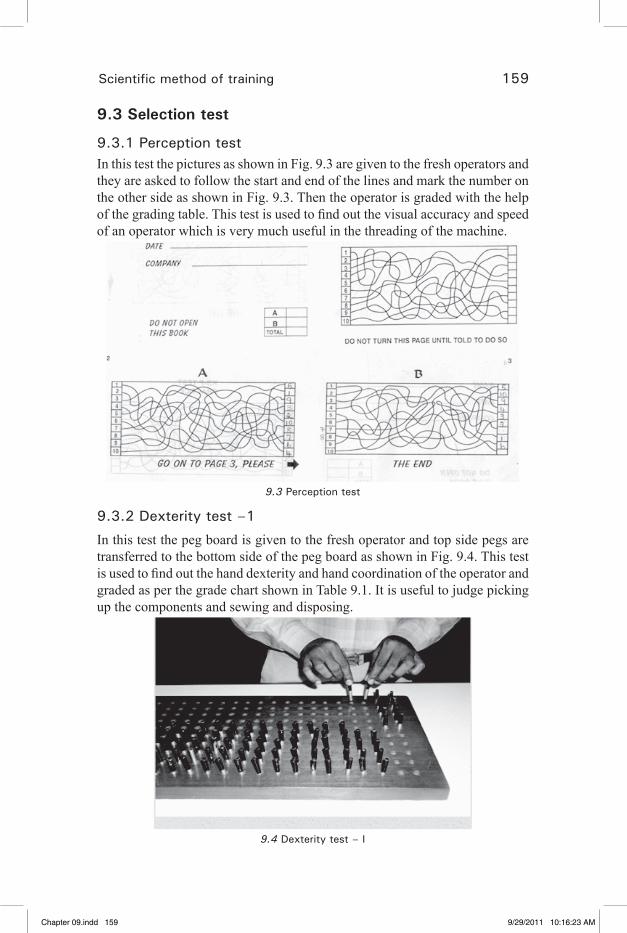
Scientific method of training 159
9.3 Selection test
9.3.1 Perception testIn this test the pictures as shown in Fig. 9.3 are given to the fresh operators and they are asked to follow the start and end of the lines and mark the number on the other side as shown in Fig. 9.3. Then the operator is graded with the help of the grading table. This test is used to find out the visual accuracy and speed of an operator which is very much useful in the threading of the machine.
9.3 Perception test
9.3.2 Dexterity test –1
In this test the peg board is given to the fresh operator and top side pegs are transferred to the bottom side of the peg board as shown in Fig. 9.4. This test is used to find out the hand dexterity and hand coordination of the operator and graded as per the grade chart shown in Table 9.1. It is useful to judge picking up the components and sewing and disposing.
9.4 Dexterity test – I
Chapter 09.indd 159 9/29/2011 10:16:23 AM
�� �� �� �� ��
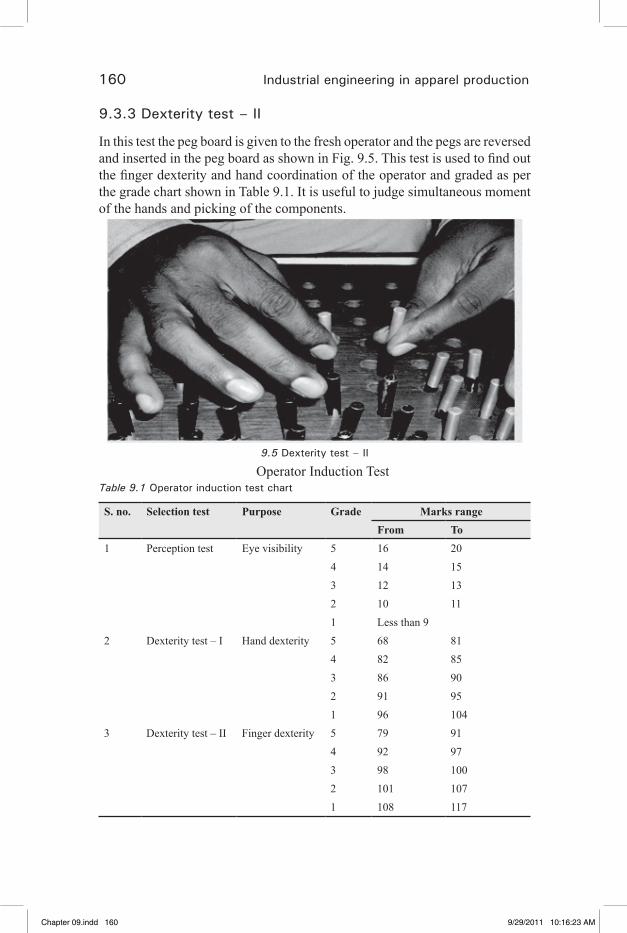
160 Industrial engineering in apparel production
9.3.3 Dexterity test – II
In this test the peg board is given to the fresh operator and the pegs are reversed and inserted in the peg board as shown in Fig. 9.5. This test is used to find out the finger dexterity and hand coordination of the operator and graded as per the grade chart shown in Table 9.1. It is useful to judge simultaneous moment of the hands and picking of the components.
9.5 Dexterity test – II
Operator Induction TestTable 9.1 Operator induction test chart
S. no. Selection test Purpose Grade Marks rangeFrom To
1 Perception test Eye visibility 5 16 204 14 153 12 132 10 111 Less than 9
2 Dexterity test – I Hand dexterity 5 68 814 82 853 86 902 91 951 96 104
3 Dexterity test – II Finger dexterity 5 79 914 92 973 98 1002 101 1071 108 117
Chapter 09.indd 160 9/29/2011 10:16:23 AM
�� �� �� �� ��

Scientific method of training 161
9.4 Basic exercise
Ball and tube exercise. In this exercise a ball is picked from right hand then inserted inside the tube, and the ball is received on the other hand (left hand) as shown in Fig. 9.6. This process continued for 25 balls one by one. Once the operator completes this process in 25 seconds then change from right hand to left hand. This exercise enhances the simultaneous motion of hand and coordination of hands.
9.6 Ball and tube exercise
Pin board – In this exercise the 3 pins out of 75 are picked from right hand then inserted inside the hole in the pin board as shown in Fig. 9.7. This process is then continued for all 75 pins. Once the operator completes this process in 25 seconds then change from right hand to left hand. This exercise enhances the finger dexterity.
9.7 Pin board
9.5 Paper exercise
The SNLS machines are adjusted to sew paper without sewing thread. The first papers sew exercise PS1as shown in Fig. 9.8 performed by the operators to get treadle control at her full speed. The goal for this exercise is that the operator should sew two lines in 4.5 s.
9.8 Paper sew exercise PS1
Chapter 09.indd 161 9/29/2011 10:16:24 AM
�� �� �� �� ��

162 Industrial engineering in apparel production
The second papers sew exercise PS2 as shown in Fig. 9.9 performed by the operators to get treadle control and start and stop control at her full speed. The goal for this exercise is that the operator should sew two lines in 5 s.
9.9 Paper sew exercise PS2
The third papers sew exercise PS3 as shown in Fig. 9.10 performed by the operators to get straight line accuracy at high speed. The goal for this exercise is that the operator should sew two lines in 7 s.
9.10 Paper sew exercise PS3
The fourth papers sew exercise PS4 as shown in Fig. 9.11 performed by the operators to get needle control at high speed. The goal for this exercise is that the operator should sew one line in 10 s.
9.11 Paper sew exercise PS4
Chapter 09.indd 162 9/29/2011 10:16:24 AM
�� �� �� �� ��

Scientific method of training 163
The fifth papers sew exercise PS5 as shown in Fig. 9.12 performed by the operators to get control on changing the direction at high speed. The goal for this exercise is that the operator should sew one line in 18 s.
9.12 Paper sew exercise PS5
The sixth papers sew exercise PS6 as shown in Fig. 9.13 performed by the operators to get curve line accuracy at high speed. The goal for this exercise is that the operator should sew two lines in 4.5 s.
9.13 Paper sew exercise PS5
9.6 Fabric exerciseThe SNLS machines are adjusted to sew fabric with sewing thread. The first fabric sews exercise FS1 as shown in Fig. 9.14 performed by the operators to get correct alignment with ¼ in. line accuracy at high speed of the fabric dimension 6 × 6 in. The goal for this exercise is that the operator should sew one piece in 18 s.
9.14 Fabric sew exercise FS1
Chapter 09.indd 163 9/29/2011 10:16:25 AM
�� �� �� �� ��
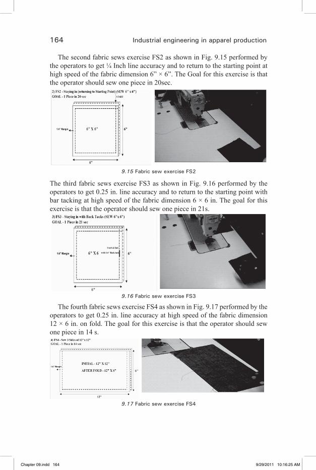
164 Industrial engineering in apparel production
The second fabric sews exercise FS2 as shown in Fig. 9.15 performed by the operators to get ¼ Inch line accuracy and to return to the starting point at high speed of the fabric dimension 6” × 6”. The Goal for this exercise is that the operator should sew one piece in 20sec.
9.15 Fabric sew exercise FS2
The third fabric sews exercise FS3 as shown in Fig. 9.16 performed by the operators to get 0.25 in. line accuracy and to return to the starting point with bar tacking at high speed of the fabric dimension 6 × 6 in. The goal for this exercise is that the operator should sew one piece in 21s.
9.16 Fabric sew exercise FS3
The fourth fabric sews exercise FS4 as shown in Fig. 9.17 performed by the operators to get 0.25 in. line accuracy at high speed of the fabric dimension 12 × 6 in. on fold. The goal for this exercise is that the operator should sew one piece in 14 s.
9.17 Fabric sew exercise FS4
Chapter 09.indd 164 9/29/2011 10:16:25 AM
�� �� �� �� ��
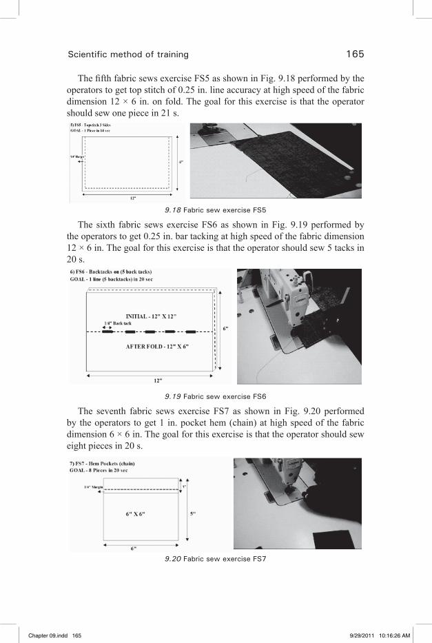
Scientific method of training 165
The fifth fabric sews exercise FS5 as shown in Fig. 9.18 performed by the operators to get top stitch of 0.25 in. line accuracy at high speed of the fabric dimension 12 × 6 in. on fold. The goal for this exercise is that the operator should sew one piece in 21 s.
9.18 Fabric sew exercise FS5
The sixth fabric sews exercise FS6 as shown in Fig. 9.19 performed by the operators to get 0.25 in. bar tacking at high speed of the fabric dimension 12 × 6 in. The goal for this exercise is that the operator should sew 5 tacks in 20 s.
9.19 Fabric sew exercise FS6
The seventh fabric sews exercise FS7 as shown in Fig. 9.20 performed by the operators to get 1 in. pocket hem (chain) at high speed of the fabric dimension 6 × 6 in. The goal for this exercise is that the operator should sew eight pieces in 20 s.
9.20 Fabric sew exercise FS7
Chapter 09.indd 165 9/29/2011 10:16:26 AM
�� �� �� �� ��
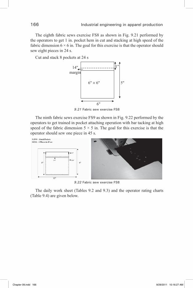
166 Industrial engineering in apparel production
The eighth fabric sews exercise FS8 as shown in Fig. 9.21 performed by the operators to get 1 in. pocket hem in cut and stacking at high speed of the fabric dimension 6 × 6 in. The goal for this exercise is that the operator should sew eight pieces in 24 s.
Cut and stack 8 pockets at 24 s
6" × 6" 5"
6"
14"margin
1"
9.21 Fabric sew exercise FS8
The ninth fabric sews exercise FS9 as shown in Fig. 9.22 performed by the operators to get trained in pocket attaching operation with bar tacking at high speed of the fabric dimension 5 × 5 in. The goal for this exercise is that the operator should sew one piece in 45 s.
9.22 Fabric sew exercise FS8
The daily work sheet (Tables 9.2 and 9.3) and the operator rating charts (Table 9.4) are given below.
Chapter 09.indd 166 9/29/2011 10:16:27 AM
�� �� �� �� ��
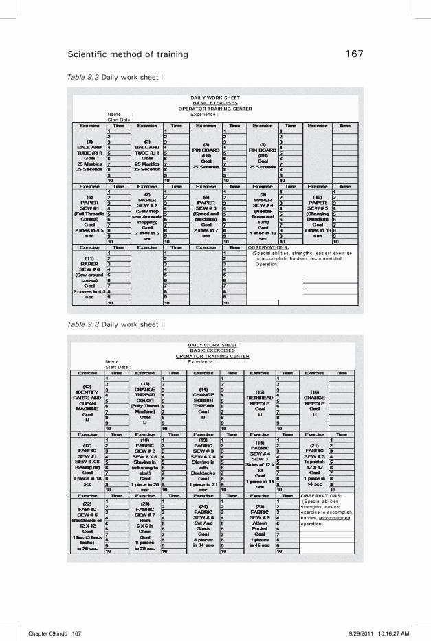
Scientific method of training 167
Table 9.2 Daily work sheet I
Table 9.3 Daily work sheet II
Chapter 09.indd 167 9/29/2011 10:16:27 AM
�� �� �� �� ��
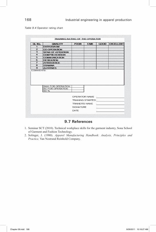
168 Industrial engineering in apparel production
Table 9.4 Operator rating chart
9.7 References
1. Seminar SCT (2010). Technical workplace skills for the garment industry, Sona School of Garment and Fashion Technology.
2. Solinger, J. (1980). Apparel Manufacturing Handbook: Analysis, Principles and Practice, Van Nostrand Reinhold Company.
Chapter 09.indd 168 9/29/2011 10:16:27 AM
�� �� �� �� ��
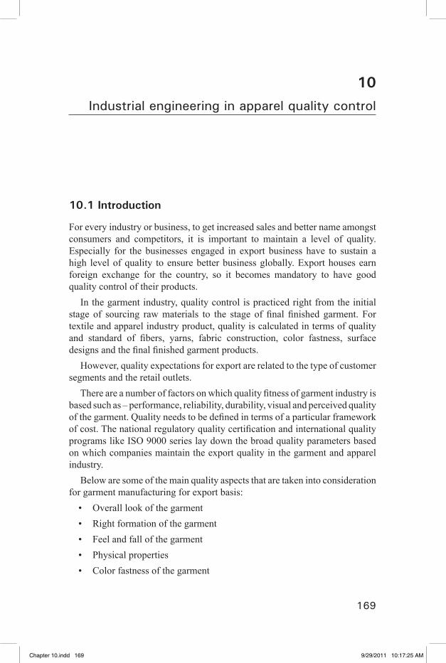
169
10Industrial engineering in apparel quality control
10.1 Introduction
For every industry or business, to get increased sales and better name amongst consumers and competitors, it is important to maintain a level of quality. Especially for the businesses engaged in export business have to sustain a high level of quality to ensure better business globally. Export houses earn foreign exchange for the country, so it becomes mandatory to have good quality control of their products.
In the garment industry, quality control is practiced right from the initial stage of sourcing raw materials to the stage of final finished garment. For textile and apparel industry product, quality is calculated in terms of quality and standard of fibers, yarns, fabric construction, color fastness, surface designs and the final finished garment products.
However, quality expectations for export are related to the type of customer segments and the retail outlets.
There are a number of factors on which quality fitness of garment industry is based such as – performance, reliability, durability, visual and perceived quality of the garment. Quality needs to be defined in terms of a particular framework of cost. The national regulatory quality certification and international quality programs like ISO 9000 series lay down the broad quality parameters based on which companies maintain the export quality in the garment and apparel industry.
Below are some of the main quality aspects that are taken into consideration for garment manufacturing for export basis:
Overall look of the garment• Right formation of the garment• Feel and fall of the garment• Physical properties• Color fastness of the garment•
Chapter 10.indd 169 9/29/2011 10:17:25 AM
�� �� �� �� ��

170 Industrial engineering in apparel production
Finishing properties• Presentation of the final garment10.1.1 Basic thumb rules for garment • exporters
For a garment exporter there are many strategies and rules that are required to be followed to achieve good business.
The quality of fabric, quality of product, delivery, price, packaging and presentation are some of the main aspects that need to be taken care of in garment export business.
Some rules that are advisable for garment exporters are listed below:Quality has to be taken care of by the vendor. Excuses for low quality • garments are not entertained in international market. For exporters, new or existing, it is mandatory to use design, technology and quality as per the buyer requirement.Apart from superior quality of the garment, its pricing, packaging, • delivery, etc., too have to be a taken care of.The garment shown in the catalogue should match with the final garment • delivered.It is important to perform according to the promises given to the buyer, • or else it creates a very bad impression and results in loss of business and reputation.In international market, quality assurance is required at every point.• Proper documentation and high standard labels on the garment are also • important aspects as these things also create good impression.Timely delivery of garments is as important as its quality.• If your competitor has the better quality of garment in same pricing, it is • better that you also enhance your garment quality.Before entering into international market, garment exporters have to • carefully frame out the quality standards and strictly follow it, or else if anything goes wrong, it could harm the reputation of organization.The garment quality should match with that of the samples shown during • taking the orders.The garment exporters should know how to negotiate a premium price • after quality assurance is done.
Chapter 10.indd 170 9/29/2011 10:17:26 AM
�� �� �� �� ��

Industrial engineering in apparel quality control 171
10.2 Quality is a multi-dimensional aspect
There are many aspects of quality based on which the garment exporters are supposed to work.
Quality of production• Quality of design of the garment• Purchasing functions – quality should be maintained• Quality of final inspection should be superior• Quality of the sales also has to be maintained•
Quality of marketing of the final product is also important as the • quality of the garment itself
Quality is ultimately a question of customer satisfaction. Good quality increases the value of a product or service, establishes brand name, and builds up good reputation for the garment exporter, which in turn results into consumer satisfaction, high sales and foreign exchange earnings for the country. The perceived quality of a garment is the result of a number of aspects, which together help achieve the desired level of satisfaction for the customer. Therefore quality control in terms of garment, pre-sales service, posts-sales service, delivery, pricing, etc., are essential for any garment exporter (Glock and Kunz, 2009).
10.2.1 To ensure quality
Recognize who the customer is• Build processes that anticipate and prevent defects• Make a plan to achieve the desired quality level• Set up ways to measure progress• Work as a team to achieve goal•
In this context, customer is the entity receiving a service or product from our work. For example, we can take a short production line.
Receiving Cutting Sewing Inspecting Finishing Quality problem in cutting may lead to problems in sewing, inspecting
and finishing. It’s like “garbage in garbage out”. In other words, one needs to have good quality materials to produce good quality goods. So this has to be applied to every process in the system to have a total quality control.
Chapter 10.indd 171 9/29/2011 10:17:26 AM
�� �� �� �� ��
172 Industrial engineering in apparel production
10.2.2 A good plan requires
(a) A clearly defined objective(b) Goals or expected results(c) The activities needed to achieve the desired results(d) Defined roles and responsibilities for the activities(e) Dates for beginning and completion of each activity(f) An analysis of potential problemsMeasurements are a vital part of any quality improvement program.
Anything that is not measured does not improve. We need to establish these standard measures and measure the progress periodically.
Team work is also an essential element for the success of the program. Remember “ONE of us is NOT better than an All of US”. The whole effort needs to have a direction that a team leader will provide.
10.3 How to control quality?
1. Have the proper approach toward operators.2. Train the operator to sew with good quality from the beginning.3. Know quality specifications and tolerance
Be sure you understand what constitutes good and poor quality.• Be consistent in your decisions toward quality.•
4. Comment on both good and bad quality. We all have a tendency to be silent during good times and vocal during the bad.
5. Be sure to check each operators work daily.6. Use a check list. Do not rely on memory of specifications.7. Do not rely on inspectors to tell you the quality level of your operators,
instead find out yourself.Do not have a compromising attitude towards problem related to quality.
10.3.1 Basic quality inspection procedure in cutting area
Marker is checked for all parts and for any variation against pattern.• Spreading has to be inspected• During cutting:•
Chapter 10.indd 172 9/29/2011 10:17:26 AM
�� �� �� �� ��
Industrial engineering in apparel quality control 173
The marker line had to be followed• All notches should be located correctly with even depth say 1/8 in. (±
1/16).When cutting, care should be taken not to shift the stack of parts to a side
or cut with the blade at an angle. In bundling and shade marking, care should be taken to ensure that the • numbering is correct.
For the final audit process, the quality inspector will determine how many bundles to check from every size depending on the sample size.
10.3.2 Basic quality control procedure in sewing line
(a) 100% inline parts checkingThe operations which are difficult to re-process after assembling is checked
100% to avoid damages and waste of time.(b) Inline inspectionDuring the production of garments the operator’s finished work is audited in
an inline inspection. A quality inspector moves from one operator to another at random inspecting a pre-determined number of parts from a finished bundle. This helps to control quality at needle point.
(c) 100% end-line inspectionAt the end of a line or section there should be a checker to inspect all the
parts before they leave the section. The inspections should be effective in identifying all defects in a garment.
The checkers should have their forms filled correctly. A good source of information to determine the quality performance of the section is the point of 100% inspection.
The section supervisor should check the quality level at the point of 100% inspection periodically. With this information, the supervisor should address the problems, correct the possible causes and make plans to prevent them.
(d) Pre-final audit A pre-final audit should be performed on packed items on a daily basis
to ensure that the good packed items are meeting the quality standards. Any problem seen can be arrested at the early stage.
If pre-final audits are done properly, the final audit of the buyer should also be carried out without any issues.
Chapter 10.indd 173 9/29/2011 10:17:26 AM
�� �� �� �� ��

174 Industrial engineering in apparel production
10.4 How to achieve good quality?
To control quality at needle point, the supervisor should create awareness in operators.
One of the tools for achieving good quality is “quality drill” (Seminar SCT, 2010).
10.4.1 Quality drill
Ask the operator to stop the work she is doing.• Give her stickers to mark defects.• Ask the operator to inspect, the bundle in which she is working on, the • bundle she has already finished, and the bundle she is going to work on next, based on the quality specifications.This way the operator has the chance to see if the work she is doing is • of good quality and also make sure the work she is receiving from the previous operation is not defective.Ask the operator to mark any part that is out of tolerance with the • sticker.Ask the operator to do it while standing up and when she is finished • she should signal the supervisor that she is ready to have the results evaluated.The supervisor should make sure that the instructions given to operator • have been understood and then leave to continue with the regular activities.When the operator has signaled that she has finished, the supervisor • returns.The supervisor then proceeds to inspect at random a number of parts of • any bundle. If she finds a defect other than those marked by the operator, then the supervisor should separate it and ask the operator why the defect was not identified. If the supervisor did not see any defect in the random check, she turns to the operator and asks the operator to show her the defective parts marked by the operator.If the operator has not found any defects, and the supervisor finds some, • she then asks the operator to explain, based on the points described in the quality specification, why she thinks this part is of acceptable quality.If defective parts have been identified then the operator should explain • why they are defective based on the points described in the quality specification.
Chapter 10.indd 174 9/29/2011 10:17:26 AM
�� �� �� �� ��
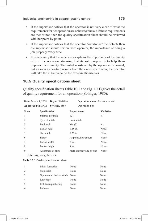
Industrial engineering in apparel quality control 175
If the supervisor notices that the operator is not very clear of what the • requirements for her operation are or how to find out if these requirements are met or not, then the quality specification sheet should be reviewed with her point by point.If the supervisor notices that the operator “overlooks” the defects then • the supervisor should review with operator, the importance of doing a job properly every time.It is necessary that the supervisor explains the importance of the quality • drill to the operators stressing that its sole purpose is to help them improve their quality. The initial resistance by the operators is normal, but as soon as positive results from the exercise are seen, the operator will take the initiative to do the exercise themselves.
10.5 Quality specifications sheet
Quality specification sheet (Table 10.1 and Fig. 10.1) gives the detail of quality requirement for an operation (Solinger, 1980):
Date: March 3, 2008 Buyer: WalMart Operation name: Packet attachedApproved by: QAM Style no. 4567 Operation no:
S. no. Specification Requirement Variation1 Stitches per inch 12 ±12 Type of stitch Lock stitch3 Back tack Yes (3) ±14 Pocket hem 1.25 in. None5 Top stitch 0.25 in. None6 Shape As per sketch/pattern None7 Pocket width 7 in. None8 Pocket height 8 in. None9 Alignment of parts Mark on body and pocket None
Stitching irregularitiesTable 10.1 Quality specification sheet
1 Stitch formation None None2 Skip stitch None None3 Open seam / broken stitch None None4 Raw edge None None5 Roll/twist/puckering None None6 Fullness None None
Chapter 10.indd 175 9/29/2011 10:17:26 AM
�� �� �� �� ��
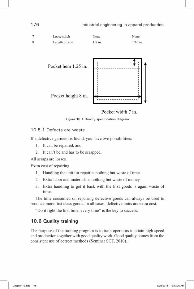
176 Industrial engineering in apparel production
7 Loose stitch None None8 Length of sew 1/8 in. 1/16 in.
Pocket height 8 in.
Pocket hem 1.25 in.
Pocket width 7 in. Figure 10.1 Quality specification diagram
10.5.1 Defects are waste
If a defective garment is found, you have two possibilities: 1. It can be repaired, and 2. It can’t be and has to be scrapped.
All scraps are losses.Extra cost of repairing
1. Handling the unit for repair is nothing but waste of time.2. Extra labor and materials is nothing but waste of money.3. Extra handling to get it back with the first goods is again waste of
time.The time consumed on repairing defective goods can always be used to
produce more first class goods. In all cases, defective units are extra cost. “Do it right the first time, every time” is the key to success.
10.6 Quality training
The purpose of the training program is to train operators to attain high speed and production together with good quality work. Good quality comes from the consistent use of correct methods (Seminar SCT, 2010).
Chapter 10.indd 176 9/29/2011 10:17:26 AM
�� �� �� �� ��

Industrial engineering in apparel quality control 177
The steps to be taken to achieve good quality are as follows:1. Initial instruction
Point out the key points of method and quality to the trainee and be sure that she understands them.
2. Trainee practice When the trainee first practices an exercise, the instructor should watch her methods very closely and correct any incorrect methods immediately. The trainee should not be timed or be permitted to start timing until she is doing the exercise correctly. Even after starting her timing, the instructor should keep a close watch on her methods and quality.
3. Quality checking Whenever the instructor finds any faulty work, or whenever defects are found by other inspectors or operators, the instructor should:
Look at the faulty work or record to determine what mistakes the • trainee is making.Tell the trainee not just what she is doing wrong, but what she must • do to perform the work correctly.
4. Methods checking The best way for an instructor to ensure good quality is by watching the trainee while he is working, by inspecting some of his work and by correcting any faults immediately. It is much easier and more effective to correct a fault when it happens, than to try to change the method after he has turned out a quantity of bad work. In order to become skilled at this part of training, the instructor should take every opportunity to stand and watch each trainee at work, in order to detect and stop any defects in method, immediately.
10.6.1 Overcoming a learning plateau
There may be times during a trainee’s progress when she stops improving on an exercise before she reaches the target. This is known as a learning plateau. At such times it is essential that the instructor help the trainee to overcome this plateau.
The following steps should be taken by the instructor to help the trainee:
10.6.2 Watch the trainee’s methods
The instructor should watch the trainee performing the exercise in and try
Chapter 10.indd 177 9/29/2011 10:17:26 AM
�� �� �� �� ��
178 Industrial engineering in apparel production
to find out what the difficulty is. The instructor should analyze the trainee’s methods carefully and check that all the key points are being done correctly. She should also try to see which part of the job seems to be slowing down the trainee.
10.6.3 Correct the method if necessary
If the trainee is using an incorrect method which can be corrected easily, the instructor should correct it immediately and have the trainee continue practicing the exercise using the correct methods. If the trainee is using an incorrect method which may be difficult to change, the instructor should take the trainee back to an earlier and simpler exercise. Then progress to the exercise where the trainee is having difficulty.
10.6.4 Look at the trainer’s records
If there is no obvious method change required, the instructor should look at the trainee and looking at the records, the instructor should be able to decide which earlier exercise should be practiced by the trainee.
10.6.5 Go back to an earlier exercise
Even if the trainee was doing well on the earlier exercise, she should go back to it in order to re-establish the correct speed of working and to restore her confidence in her own ability. If the trainee was having difficulty with the earlier exercise, the instructor should work with her while she is practicing it. The instructor should encourage the trainee, praise her when she improves a little, try to get her to improve a little more, and stay with her until she improves.
10.6.6 Practice the original exercise again
Once the trainee has performed the earlier exercise successfully, she should practice the original exercise on which she was having difficulty. Before starting, the instructor should explain to the trainee that she has shown how well she can do on the earlier exercise, and with just little extra effort can improve on this exercise and break through the plateau. The instructor should stay with the trainee until she improves, encouraging her, timing her and getting her to rest between attempts. Commenting on her times and progress can show the trainee that the instructor believes she can make it.
These “breakthrough” sessions are essential to the success of many trainees who might otherwise become discouraged by their lack of progress. The important factors in a successful breakthrough session are as follows:
Chapter 10.indd 178 9/29/2011 10:17:26 AM
�� �� �� �� ��
Industrial engineering in apparel quality control 179
Analyzing the trainee’s difficulties correctly.• Going back to an earlier stage to restore the trainee’s speed and self-• confidence.Explaining to the trainee exactly what is happening.• Getting the trainee to put in a little extra effort.• Staying with the trainee to help, guide and encourage.•
10.7 References
1. Glock, R. E. and Kunz, G. I. (2009). Apparel manufacturing analysis, Sewn Product Analysis, 4th edn, Pearson.
2. Solinger, J. (1980). Apparel Manufacturing Handbook: Analysis, Principles and Practice, Van nostrand Reinhold Company.
3. Seminar SCT (2010). Technical workplace skills for the garment industry, Sona School of Garment and Fashion Technology.
Chapter 10.indd 179 9/29/2011 10:17:26 AM
�� �� �� �� ��
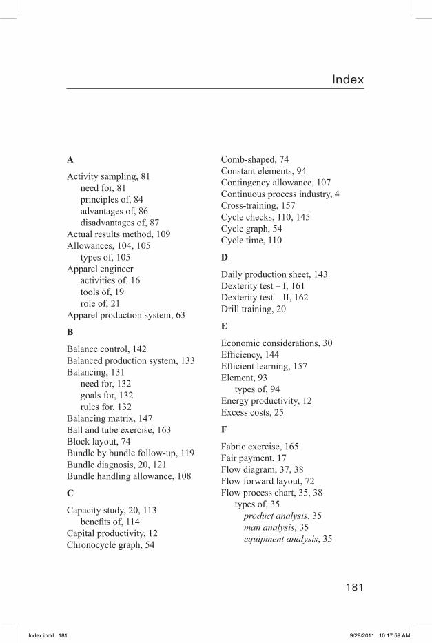
181
Index
A
Activity sampling, 81need for, 81principles of, 84advantages of, 86disadvantages of, 87
Actual results method, 109Allowances, 104, 105
types of, 105Apparel engineer
activities of, 16tools of, 19role of, 21
Apparel production system, 63
B
Balance control, 142Balanced production system, 133Balancing, 131
need for, 132goals for, 132rules for, 132
Balancing matrix, 147Ball and tube exercise, 163Block layout, 74Bundle by bundle follow-up, 119Bundle diagnosis, 20, 121Bundle handling allowance, 108
C
Capacity study, 20, 113benefits of, 114
Capital productivity, 12Chronocycle graph, 54
Comb-shaped, 74Constant elements, 94Contingency allowance, 107Continuous process industry, 4Cross-training, 157Cycle checks, 110, 145Cycle graph, 54Cycle time, 110
D
Daily production sheet, 143Dexterity test – I, 161Dexterity test – II, 162Drill training, 20
E
Economic considerations, 30Efficiency, 144Efficient learning, 157Element, 93
types of, 94Energy productivity, 12Excess costs, 25
F
Fabric exercise, 165Fair payment, 17Flow diagram, 37, 38Flow forward layout, 72Flow process chart, 35, 38
types of, 35product analysis, 35man analysis, 35equipment analysis, 35
Index.indd 181 9/29/2011 10:17:59 AM

182 Industrial engineering in apparel production
Follow-up study, 20Follow-ups, 119
benefits of, 119types of, 119
Foreign elements, 94
G
Global efficiency, 118Governing elements, 94Group system, 64, 65
advantages of, 65disadvantages of, 66
H
Human considerations, 31
I
Improvement methods, 61Incentive plans, 20Industrial engineering, 15. See also
apparel engineering, 18 techniques for, 18
Initial balance, 136Inline inspection, 175Interference allowance, 107Intermittent process industry, 5
J
Job analysis, 155Job exercise, 159Job selection, 91
L
Labor mix, 11Labor productivity, 11Labor requirement, 134Land productivity, 12Layout designing, 74Line balancing, 131Line imbalance, 142Line, 131Linear layout, 73
Lost time, 146
M
Machine allowances, 105Machine elements, 94Machine productivity, 11Manual elements, 94Material productivity, 12Material wastage, 27Method analysis, 19, 29
objectives of, 29procedure for, 30
Method study, 15, 29Micro motion study, 52Motion economy, 47Motion study, 29Movements, 49
classification of, 49, 50
N
Normal performance, 101Numbering, 33
O
Objective rating, 104Occasional elements, 94Off-standard time, 118On-standard efficiency, 118Operation breakdown, 134, 135Operation bulletin, 124Operator performance, 117Outline process chart, 33Overall productivity, 12, 13
P
Paper exercise, 163Performance rating, 101
methods of, 102Pre-determined motion–time system (PMTS), 108Process allowance, 107Process chart symbols, 32
Index.indd 182 9/29/2011 10:17:59 AM
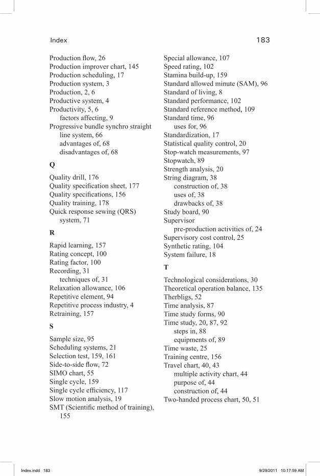
Index 183
Production flow, 26Production improver chart, 145Production scheduling, 17Production system, 3Production, 2, 6Productive system, 4Productivity, 5, 6
factors affecting, 9Progressive bundle synchro straight
line system, 66advantages of, 68disadvantages of, 68
Q
Quality drill, 176Quality specification sheet, 177Quality specifications, 156Quality training, 178Quick response sewing (QRS)
system, 71
R
Rapid learning, 157Rating concept, 100Rating factor, 100Recording, 31
techniques of, 31Relaxation allowance, 106Repetitive element, 94Repetitive process industry, 4Retraining, 157
S
Sample size, 95Scheduling systems, 21Selection test, 159, 161Side-to-side flow, 72SIMO chart, 55Single cycle, 159Single cycle efficiency, 117Slow motion analysis, 19SMT (Scientific method of training),
155
Special allowance, 107Speed rating, 102Stamina build-up, 159Standard allowed minute (SAM), 96Standard of living, 8Standard performance, 102Standard reference method, 109Standard time, 96
uses for, 96Standardization, 17Statistical quality control, 20Stop-watch measurements, 97Stopwatch, 89Strength analysis, 20String diagram, 38
construction of, 38uses of, 38drawbacks of, 38
Study board, 90Supervisor
pre-production activities of, 24Supervisory cost control, 25Synthetic rating, 104System failure, 18
T
Technological considerations, 30Theoretical operation balance, 135Therbligs, 52Time analysis, 87Time study forms, 90Time study, 20, 87, 92
steps in, 88equipments of, 89
Time waste, 25Training centre, 156Travel chart, 40, 43
multiple activity chart, 44purpose of, 44construction of, 44
Two-handed process chart, 50, 51
Index.indd 183 9/29/2011 10:17:59 AM

184 Industrial engineering in apparel production
U
U-shaped, 73Unit production system (UPS), 69
features of, 69advantages of, 70disadvantages of, 71
V
Variable elements, 94
W
Watchfulness, 27Westinghouse system of rating, 102
Whole garment production system, 64advantages of, 64disadvantages of, 64
Work cycle, 93Work in process (WIP), 122Work measurement, 15, 79
purpose of, 79uses of, 79, 80basic procedure of, 80techniques of, 80, 81
Work selection, 30Work study, 15, 16
Index.indd 184 9/29/2011 10:17:59 AM