industrial buildings at sobralinho, v.f. xira · industrial buildings at sobralinho, v.f. xira...
TRANSCRIPT
1
Industrial buildings at Sobralinho, V.F. Xira
Geotechnical aspects on the behavior of the structures and access roads
André Sampaio1
1M.Sc. Student, Instituto Superior Técnico, Av. Rovisco Pais, 1, 1049-001 Lisbon, Portugal;
ABSTRACT: Soft soils have been subject of research for many years, the main focus being the hydro-
mechanical behavior and numerical modeling of these soils. A case-study located near the Tagus river
where industrial buildings are founded on soft soil is presented. The soil is characterized after a
specific site investigation, which comprised field and laboratory tests. A comparison is made between
the implemented foundation solution, the solution proposed by the designer and alternative solutions
typically used in geological scenarios comprising soft soils. A numerical analysis was undertaken
using a 2D finite element software to understand the performance of each solution, which were then
priced and the cost-benefit relations assessed. The implemented foundation for the buildings
comprised a piled raft whereas the alternative systems considered were forced drainage and
vibroreplacement stone columns.
KEY-WORDS: Soft soils, soil characterization, foundation solutions, 2D FE analysis
1. INTRODUCTION
The expansion of urban areas leads to the search for new locations for the construction of civil
engineering works, some of which are considered complex and challenging in terms of various
constraints and difficulties in the design of the project. The presence of soft soils in the foundation of
buildings and embankments is a problem that is increasingly emerging with the expansion of urban
areas. In these cases, building loads can generate large settlements which evolve over time, and may
prevent a shallow foundation solution. This therefore requires the search for a solution of deep
foundation or soil treatment to ensure an effective foundation solution of the structure and services.
In this context, a construction site located in Sobralinho, Vila Franca de Xira, was subject of study. The
development included the construction of eight industrial buildings on soft ground. A deep foundation
solution comprising piles was proposed for the buildings. The pavements of the access roads were
constituted of embankments, and light weight fill was proposed by the designer in some areas.
However, the actual construction on site of these embankments used traditional fill, bringing great
concerns about the serviceability of the buildings and access roads in the medium and long term.
The construction site is the basis of the present dissertation, its main goals being: the characterization
of the soft soil based on in situ and laboratory tests; the evaluation of the local conditions; and the
comparative analysis of the performance of the implemented and alternative foundation solutions in
terms of movements and costs. The alternative solutions comprise the solution proposed initially by
the designer, force drainage using geodrains and vibroreplacement stone columns. Each solution was
modelled with a 2D finite element software.
2
2. CASE STUDY: INDUSTRIAL BUILDINGS IN SOBRALINHO
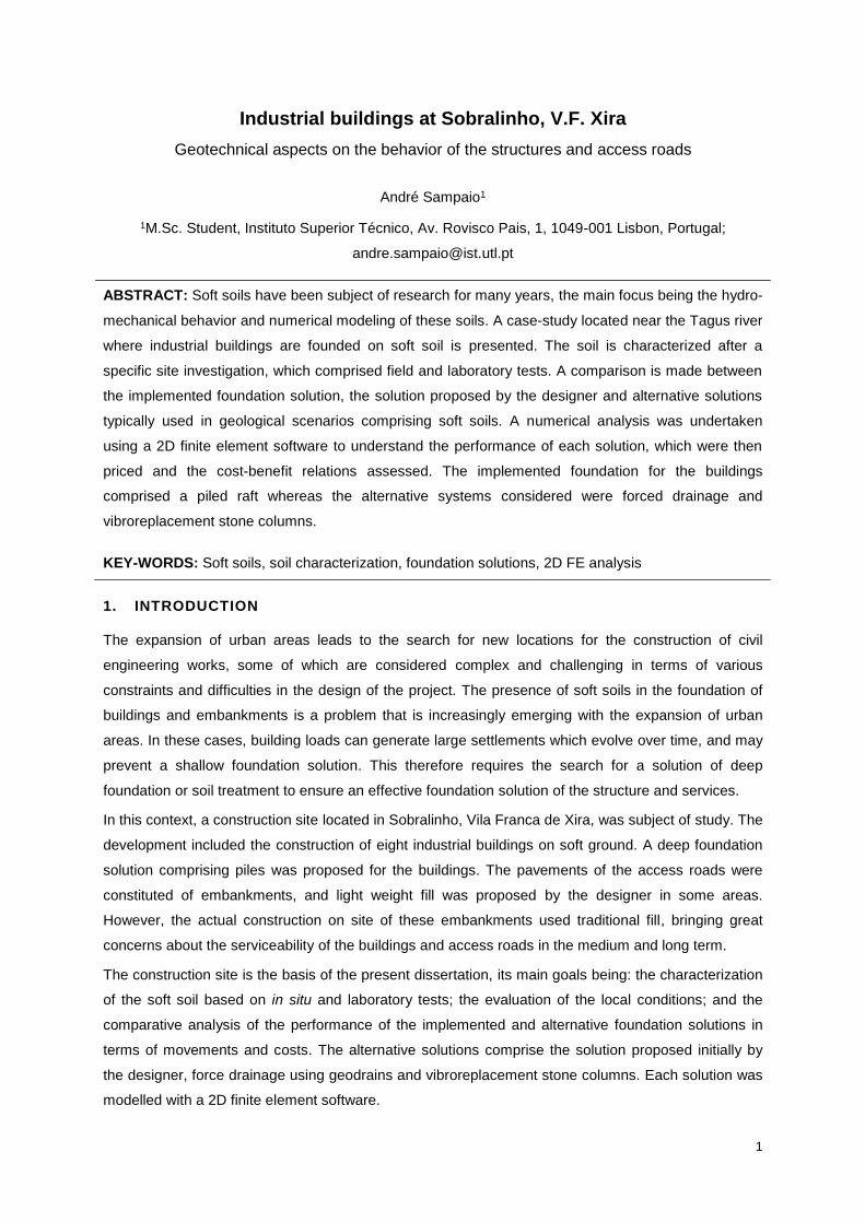
The case-study of this dissertation is a development of eight industrial two-storey buildings to be
mainly used as storage and office area. The site is located in Sobralinho, V.F.Xira and it lies
approximately 150m from the Tagus River (Fig. 1). The buildings are named “A” to “H” and each one
is about 40x60 m2 excepts for building “H” whose size is 20x60 m2. The structure of the buildings
comprises with prefabricated concrete beams and columns. Access roads surround the buildings.
Fig. 1 – Location and delimitation of the construction work site
2.1 Site investigation
The site is located in an area where Tagus River alluvial deposits exist. These are recent deposits
dating from the Holocene era and comprising silty clays, silts and organic clays. These formations are
underlain by Miocene-age formations consisting of silty-sandy clays, sandy silts and sands medium to
coarse grained. Made Ground comprising sandy material with scattered fragments of varied nature
was encountered overlying the alluvium deposits.
In order to characterize the formations present at the work site, the Client has completed a program of
site investigation works. The information available from this survey campaign consisted of nine
boreholes, carried out using drilling rigs, where SPT tests were performed; eleven static penetration
tests with pore pressure measurement (CPTU), together with dissipation tests; and seven oedometer
tests on MOSTAP soil samples taken at four different locations in plan. Given the local geology and
the high loads carried by the vertical elements of the building, a deep foundation solution was adopted
in order to ensure an appropriate transmission of the loads to the sandy substrate of Miocene age.
2.2 Foundation system for the industrial buildings
The proposed foundation solution of the industrial buildings consisted of deep foundations comprising
reinforced concrete piles with a nominal diameter of Ø600 mm or Ø800 mm for the foundation of the
structural columns. Additionally, unreinforced concrete piles with a nominal diameter of Ø500 mm
were adopted for the foundation of the groundfloor slabs from half of building "C" to building "H".
3
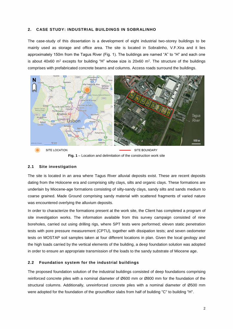
The pile capacity was assumed to be mainly due to end-bearing capacity with minimal contribution of
the shaft resistance. As such, the length of the piles was determined by the depth of bearing stratum
(NSPT > 60), with the piles penetrating three diameters deep into it. A grid of foundation beams
connecting the piles caps was designed to resist to bending moments transmitted by the structural
columns. The ground floors of the buildings are constructed on a load transfer platform which is
founded on concrete piles as shown in Fig. 2 and as explained in Sampaio (2014).
Fig. 2 – Cross-section of the adopted foundation system for the buildings
2.3 Foundation solution for the access roads
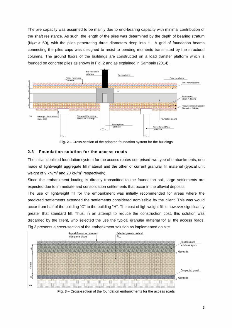
The initial idealized foundation system for the access routes comprised two type of embankments, one
made of lightweight aggregate fill material and the other of current granular fill material (typical unit
weight of 9 kN/m3 and 20 kN/m3 respectively).
Since the embankment loading is directly transmitted to the foundation soil, large settlements are
expected due to immediate and consolidation settlements that occur in the alluvial deposits.
The use of lightweight fill for the embankment was initially recommended for areas where the
predicted settlements extended the settlements considered admissible by the client. This was would
accur from half of the building "C" to the building "H". The cost of lightweight fill is however significantly
greater that standard fill. Thus, in an attempt to reduce the construction cost, this solution was
discarded by the client, who selected the use the typical granular material for all the access roads.
Fig.3 presents a cross-section of the embankment solution as implemented on site.
Fig. 3 – Cross-section of the foundation embankments for the access roads
4
3. GEOTECHNICAL CARACTERIZATION
3.1 Ground Profile and Soil Classification
From the analysis and classification of samples recovered from the boreholes, it was possible to
describe the geology of the site, which is summarized in Table 1.
Table 1 – Geological reconnaissance of the study area
EPOCH FORMATION LITHOLOGY
Present Made Ground Fill of sandy to silty nature, reddish-brown, with disperse fragments of varied nature.
Deposits of silty to sandy nature, dark brown, with roots on top.
Holocene Alluvium
Reddish-brown and greyish sandy CLAY, with local interlayers of organic material
and disperse coarse flint GRAVEL.
Dark grey clayey MUD. Dark grey muddy CLAY.
Miocene Areolas de
Cabo Ruivo
Brown to red silty and sandy CLAY. Orange sandy SILT.
Orange medium to coarse SAND with coarse subrounded flint GRAVEL.
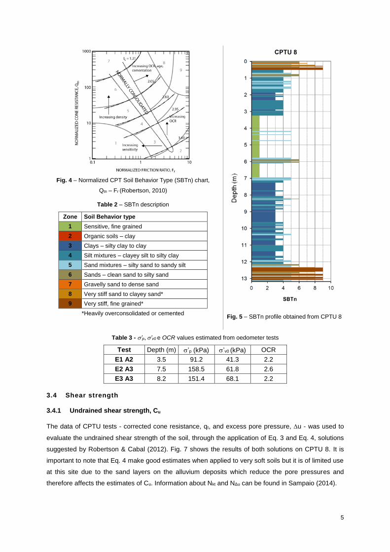
In order to collect more information about the ground profile and soil types, data from the CPTU test
were also used. Some of the derived values from this test are the friction ratio, Rf, the corrected cone
resistance, qt, and the excess pore pressure, ∆u. Ground profiling is one of the main applications of
this test and for this purpose the classification suggested by Robertson (1990, updated in 2010) was
adopted. The author proposed a chart (Fig. 4) that relates the normalized cone resistance, Qtn, to the
normalized friction ratio, Fr, creating in this domain (Qtn - Fr), areas indicating different soil behavior
types (SBTn), which are described in Table 2. An example of the output of this analysis made in CPTU
8 is presented in Fig. 5. This process was repeated for the total number of CPTU tests.
Colours were assigned to each SBT zone to facilitate the visualization and interpretation of profiles.
3.2 Soil Unit Weight
The unit weight was estimated based on CPTU results by applying the correlation (Eq. 1) suggested
by Robertson (2010), which made possible a continuous study of this property on the foundation soil.
236.1pqlog36.0Rlog27.0 atfw (Eq. 1)
pa = atmospheric pressure = 100 kPa
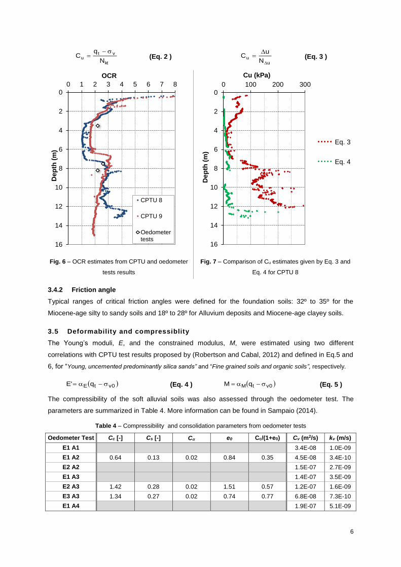
3.3 Stress History
The preconsolidation stress, ’p, was determined in 3 oedometer tests using the method proposed by
ASTM D2435. The in-situ effective overburden stress, ’v0, is estimated with the information of the 2
closest CPTU tests (unit weight and excess of pore pressure). Knowing ’p and ’v0 the
Overconsolidation Ratio, OCR, is determined dividing the first by the latter. The results are
summarized in Table 3. The three samples are typically organic clays. The CPTU tests also allowed
an estimate of OCR with depth as explained in Sampaio (2014). The method used proved to be very
accurate when comparing the estimates with the ones from the oedometer tests results on close
locations. Fig. 6 presents the estimates resultant from both tests.
5
Fig. 4 – Normalized CPT Soil Behavior Type (SBTn) chart,
Qtn – Fr (Robertson, 2010)
Fig. 5 – SBTn profile obtained from CPTU 8
Table 2 – SBTn description
Zone Soil Behavior type
1 Sensitive, fine grained
2 Organic soils – clay
3 Clays – silty clay to clay
4 Silt mixtures – clayey silt to silty clay
5 Sand mixtures – silty sand to sandy silt
6 Sands – clean sand to silty sand
7 Gravelly sand to dense sand
8 Very stiff sand to clayey sand*
9 Very stiff, fine grained*
*Heavily overconsolidated or cemented
Table 3 - ’p, ’v0 e OCR values estimated from oedometer tests
Test Depth (m) ’p (kPa) ’v0 (kPa) OCR
E1 A2 3.5 91.2 41.3 2.2
E2 A3 7.5 158.5 61.8 2.6
E3 A3 8.2 151.4 68.1 2.2
3.4 Shear strength
3.4.1 Undrained shear strength, Cu
The data of CPTU tests - corrected cone resistance, qt, and excess pore pressure, u - was used to
evaluate the undrained shear strength of the soil, through the application of Eq. 3 and Eq. 4, solutions
suggested by Robertson & Cabal (2012). Fig. 7 shows the results of both solutions on CPTU 8. It is
important to note that Eq. 4 make good estimates when applied to very soft soils but it is of limited use
at this site due to the sand layers on the alluvium deposits which reduce the pore pressures and
therefore affects the estimates of Cu. Information about Nkt and NΔu can be found in Sampaio (2014).
6
kt
vtu
N
qC
(Eq. 2 )
uu
N
uC
(Eq. 3 )
Eq. 3
Eq. 4
Fig. 6 – OCR estimates from CPTU and oedometer
tests results
Fig. 7 – Comparison of Cu estimates given by Eq. 3 and
Eq. 4 for CPTU 8
3.4.2 Friction angle
Typical ranges of critical friction angles were defined for the foundation soils: 32º to 35º for the
Miocene-age silty to sandy soils and 18º to 28º for Alluvium deposits and Miocene-age clayey soils.
3.5 Deformability and compressiblity
The Young’s moduli, E, and the constrained modulus, M, were estimated using two different
correlations with CPTU test results proposed by (Robertson and Cabal, 2012) and defined in Eq.5 and
6, for “Young, uncemented predominantly silica sands” and “Fine grained soils and organic soils”, respectively.
0vtE q'E (Eq. 4 )
0vtM qM (Eq. 5 )
The compressibility of the soft alluvial soils was also assessed through the oedometer test. The
parameters are summarized in Table 4. More information can be found in Sampaio (2014).
Table 4 – Compressibility and consolidation parameters from oedometer tests
Oedometer Test Cc [-] Cs [-] C e0 Cc/(1+e0) Cv (m2/s) kv (m/s)
E1 A1 3.4E-08 1.0E-09
E1 A2 0.64 0.13 0.02 0.84 0.35 4.5E-08 3.4E-10
E2 A2 1.5E-07 2.7E-09
E1 A3 1.4E-07 3.5E-09
E2 A3 1.42 0.28 0.02 1.51 0.57 1.2E-07 1.6E-09
E3 A3 1.34 0.27 0.02 0.74 0.77 6.8E-08 7.3E-10
E1 A4 1.9E-07 5.1E-09
0
2
4
6
8
10
12
14
16
0 1 2 3 4 5 6 7 8
Dep
th (
m)
OCR
CPTU 8
CPTU 9
Oedometertests
0
2
4
6
8
10
12
14
16
0 100 200 300
Dep
th (
m)
Cu (kPa)
7
3.6 Consolidation and hydraulic conductivity
The soil consolidation parameters, Ch and Cv, and hydraulic conductivity, k, were estimated from the
dissipation tests conducted in three of the CPTU tests and from all of the oedometer test. The method
suggested by Burns and Mayne (1998) for the determination of the parameter Ch was used. The
application of this method resulted Table 5. More information can be found in Sampaio (2014).
Table 5 – Ch and kh values determined from the dissipation tests
Test Depth (m) Ch (m2/s) M (MPa) kh (m/s)
CPTU 2 8.20 1.70E-07 48.5 3.44E-11
CPTU 5 5.99 2.50E-08 50.9 4.81E-12
CPTU 5 7.20 1.20E-06 85.1 1.38E-10
CPTU 6 3.86 2.00E-07 1.8 1.10E-09
CPTU 6 8.32 3.70E-08 36.7 9.88E-12
CPTU 6 10.95 1.75E-07 24.3 7.07E-11
The coefficient of consolidation, Cv, and the respective coefficient of permeability, kv, were also
calculated using Eq. 7 to Eq. 9 knowing t90 (time necessary to reach 90% of the dissipation of excess
pore pressures) for each loading stage. The mean values for all loading stages are shown in Table 4.
90
290
vt
hTC
(Eq. 6 ) vwv mCk (Eq. 7 )
'
e
e1
1m
0v
(Eq. 8 )
3.7 Design Ground Profile: Geotechnical zones and parameters
The aforementioned parameters assess were used to define geotechnical zones where soils had
similar hydro-mechanical behavior, but not necessarily the same geological lithology. Tables 6 and 7
show the geotechnical zones considered (ZG4 to ZG0) and their relevant geotechnical parameters.
Table 6 – Description of each geotechnical zone considered
GEOTECHNICAL ZONE ZG4 ZG3 ZG2 ZG1 ZG0
TYPICAL DESCRIPTION Muddy clay
Made ground and overconsolidated
muddy clay
Very stiff silty to sandy clay
Hard silty to sandy clay
Dense sand and silty sand
Table 7 – Geotechnical parameters of the soil
Parameter ZG4 ZG3 ZG2 ZG1 ZG0
Unit weight, (kN/m3) 14 - 16 16 - 18 18 - 20 19 - 20 20 - 22
Vertical hydraulic conductivity, (m/s) kv 2.2x10⁻⁹ 2.2x10⁻⁹ 1.2x10⁻⁸ 1.2x10⁻⁸ 5.0x10⁻⁶
Young’s moduli, (MPa) E’ - - 25 - 40 40 - 80 > 80
Poisson coefficient 0.30 0.30 0.30 0.30 0.30
Undrained shear strength, (kPa) Cu 10 - 20 40 - 120 120 - 200 > 200 20
Friction angle, (º) 24 24 24 26 34
Compression index Cc 1.14 1.14 - - -
Recompression index Cs 0.23 0.23 - - -
Creep index C 0.02 0.02 - - -
Initial void ratio e0 1.03 1.03 - - -
Overconsolidation ratio OCR 1.00 3.00 - - -
8
4. NUMERIC MODELLING
4.1 Method of Analysis
A 2D finite element software was used to model different foundation solutions. The aim was to predict
the settlements resulting from the construction of the buildings and the embankments in the most
critical areas. The model used the geotechnical zones and parameters described in Section 3.7, to
which were assigned different constitutive models. The soft-soil-creep model was used for the very
soft materials (i.e. ZG4 and ZG3) since it takes into account most of the aspects of the complex
stress-strain behavior of these soils. The Mohr-Coulomb model was chosen for the remaining
materials since these would not make a strong influence on the global behavior of the solution.
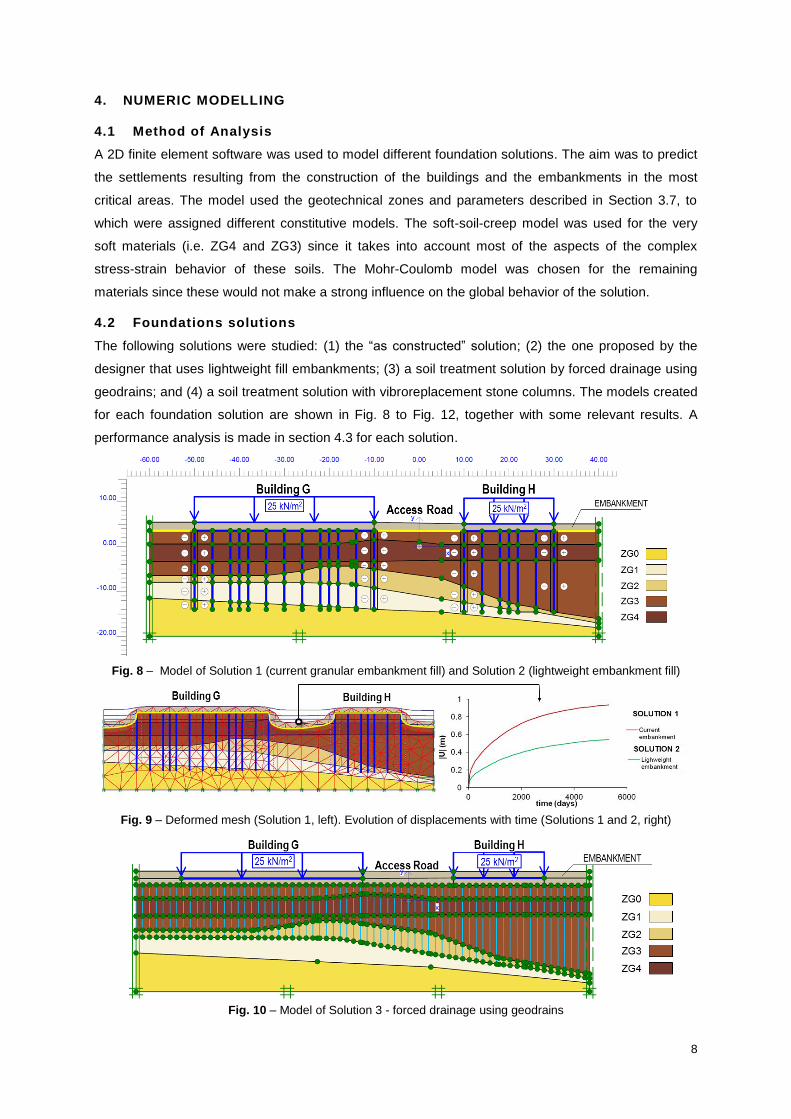
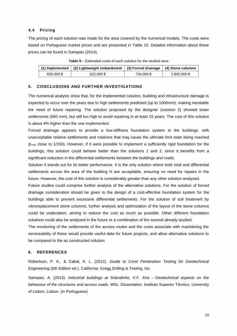
4.2 Foundations solutions
The following solutions were studied: (1) the “as constructed” solution; (2) the one proposed by the
designer that uses lightweight fill embankments; (3) a soil treatment solution by forced drainage using
geodrains; and (4) a soil treatment solution with vibroreplacement stone columns. The models created
for each foundation solution are shown in Fig. 8 to Fig. 12, together with some relevant results. A
performance analysis is made in section 4.3 for each solution.
Fig. 8 – Model of Solution 1 (current granular embankment fill) and Solution 2 (lightweight embankment fill)
Fig. 9 – Deformed mesh (Solution 1, left). Evolution of displacements with time (Solutions 1 and 2, right)
Fig. 10 – Model of Solution 3 - forced drainage using geodrains
9
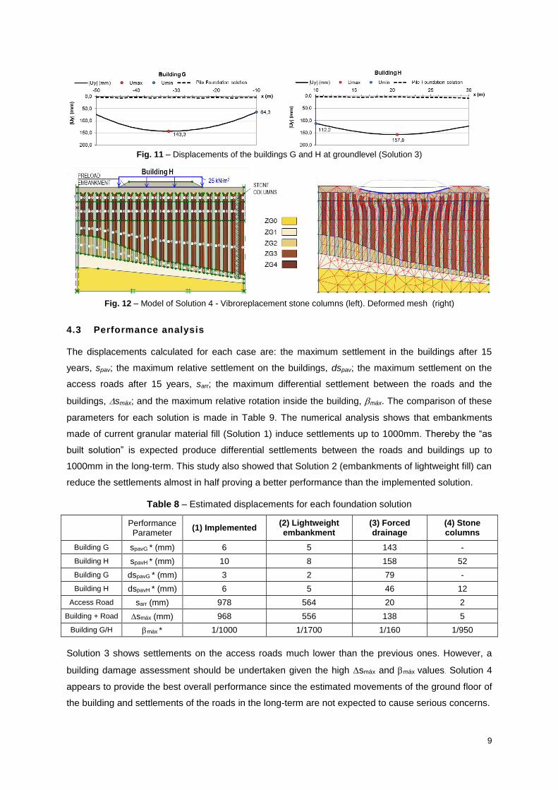
Fig. 11 – Displacements of the buildings G and H at groundlevel (Solution 3)
Fig. 12 – Model of Solution 4 - Vibroreplacement stone columns (left). Deformed mesh (right)
4.3 Performance analysis
The displacements calculated for each case are: the maximum settlement in the buildings after 15
years, spav; the maximum relative settlement on the buildings, dspav; the maximum settlement on the
access roads after 15 years, sarr; the maximum differential settlement between the roads and the
buildings, smáx; and the maximum relative rotation inside the building, máx. The comparison of these
parameters for each solution is made in Table 9. The numerical analysis shows that embankments
made of current granular material fill (Solution 1) induce settlements up to 1000mm. Thereby the “as
built solution” is expected produce differential settlements between the roads and buildings up to
1000mm in the long-term. This study also showed that Solution 2 (embankments of lightweight fill) can
reduce the settlements almost in half proving a better performance than the implemented solution.
Table 8 – Estimated displacements for each foundation solution
Performance Parameter
(1) Implemented (2) Lightweight embankment
(3) Forced drainage
(4) Stone columns
Building G spavG * (mm) 6 5 143 -
Building H spavH * (mm) 10 8 158 52
Building G dspavG * (mm) 3 2 79 -
Building H dspavH * (mm) 6 5 46 12
Access Road sarr (mm) 978 564 20 2
Building + Road smáx (mm) 968 556 138 5
Building G/H máx * 1/1000 1/1700 1/160 1/950
Solution 3 shows settlements on the access roads much lower than the previous ones. However, a
building damage assessment should be undertaken given the high smáx and máx values. Solution 4
appears to provide the best overall performance since the estimated movements of the ground floor of
the building and settlements of the roads in the long-term are not expected to cause serious concerns.
10
4.4 Pricing
The pricing of each solution was made for the area covered by the numerical models. The costs were
based on Portuguese market prices and are presented in Table 10. Detailed information about these
prices can be found in Sampaio (2014).
Table 9 – Estimated costs of each solution for the studied area
(1) Implemented (2) Lightweight embankment (3) Forced drainage (4) Stone columns
600,000 € 622,000 € 734,000 € 2,800,000 €
5. CONCLUSIONS AND FURTHER INVESTIGATIONS
The numerical analysis show that, for the implemented solution, building and infrastructure damage is
expected to occur over the years due to high settlements predicted (up to 1000mm), making inevitable
the need of future repairing. The solution proposed by the designer (solution 2) showed lower
settlements (560 mm), but still too high to avoid repairing in at least 15 years. The cost of this solution
is about 4% higher than the one implemented.
Forced drainage appears to provide a low-stiffness foundation system to the buildings, with
unacceptable relative settlements and rotations that may cause the ultimate limit state being reached
(máx close to 1/150). However, if it were possible to implement a sufficiently rigid foundation for the
buildings, this solution could behave better than the solutions 1 and 2, since it benefits from a
significant reduction in the differential settlements between the buildings and roads.
Solution 4 stands out for its better performance. It is the only solution where both total and differential
settlements across the area of the building H are acceptable, ensuring no need for repairs in the
future. However, the cost of this solution is considerably greater than any other solution analyzed.
Future studies could comprise further analysis of the alternative solutions. For the solution of forced
drainage consideration should be given to the design of a cost-effective foundation system for the
buildings able to prevent excessive differential settlements. For the solution of soil treatment by
vibroreplacement stone columns, further analysis and optimization of the layout of the stone columns
could be undertaken, aiming to reduce the cost as much as possible. Other different foundation
solutions could also be analyzed in the future or a combination of the several already studied.
The monitoring of the settlements of the access routes and the costs associate with maintaining the
serviceability of these would provide useful data for future projects, and allow alternative solutions to
be compared to the as constructed solution.
6. REFERENCES
Robertson, P. K., & Cabal, K. L. (2012). Guide to Cone Penetration Testing for Geotechnical
Engineering (5th Edition ed.). California: Gregg Drilling & Testing, Inc.
Sampaio, A. (2014). Industrial buildings at Sobralinho, V.F. Xira - Geotechnical aspects on the
behaviour of the structures and access roads. MSc. Dissertation. Instituto Superior Técnico, University
of Lisbon, Lisbon. (in Portuguese)