inductors a coil of wire can create a magnetic field if a current is run through it. if that current...
TRANSCRIPT
InductorsA coil of wire can create a magnetic field if a
current is run through it. If that current changes (as in the AC case), the magnetic field created by the coil will change. Will this changing magnetic field through the coil cause a voltage to be created across the coil? YES!
This is called self-inductance and is the basis behind the circuit element called the inductor.

Inductors
Since the voltage created depends in this case on the changing magnetic field, and the field depends on the changing current, we have: Vinductor = -L dI /dt
where the L (called the inductance) depends on the shape and material (just like capacitance and resistance).
Inductors
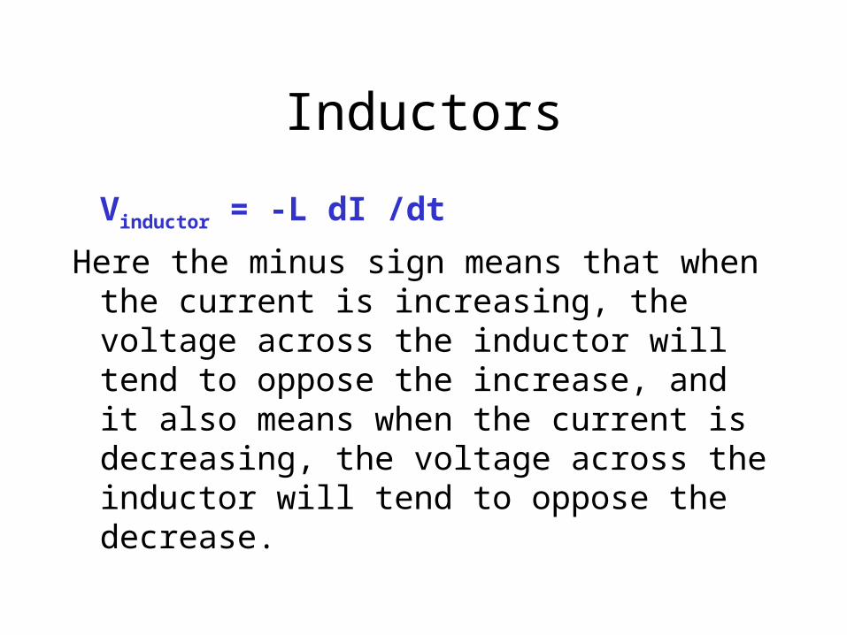
Vinductor = -L dI /dt
Here the minus sign means that when the current is increasing, the voltage across the inductor will tend to oppose the increase, and it also means when the current is decreasing, the voltage across the inductor will tend to oppose the decrease.

Units: Henry
From Vinductor = -L dI /dt
L has units of Volt / [Amp/sec] which is called a Henry:
1 Henry = Volt-sec / Amp .
This is the same unit we had for mutual inductance before (recall the transformer).

Solenoid type inductor
For a capacitor, we started with a parallel plate configuration since the parallel plates provided a uniform electric field between the plates.
In the same way, we will start with a device that provides a uniform magnetic field inside the device: a solenoid.
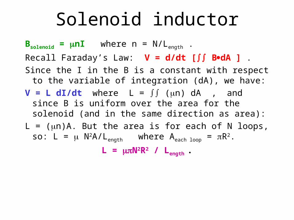
Solenoid inductorBsolenoid = nI where n = N/Length .
Recall Faraday’s Law: V = d/dt [ BdA ] .
Since the I in the B is a constant with respect to the variable of integration (dA), we have:
V = L dI/dt where L = (n) dA , and since B is uniform over the area for the solenoid (and in the same direction as area):
L = (n)A. But the area is for each of N loops, so: L = N2A/Length where Aeach loop = R2.
L = N2R2 / Length .
Size of a Henry
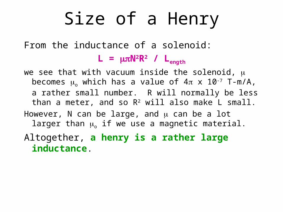
From the inductance of a solenoid:
L = N2R2 / Length
we see that with vacuum inside the solenoid, becomes o which has a value of 4 x 10⁻⁷ T-m/A, a rather small number. R will normally be less than a meter, and so R2 will also make L small.
However, N can be large, and can be a lot larger than o if we use a magnetic material.
Altogether, a henry is a rather large inductance.
Inductors
Lsolenoid = N2R2 / Length .
As we indicated before, the value of the inductance depends only on the shape (R, Length, N) and materials ().
The inductance relates the voltage across it to the changing current through it:
V = - L dI/dt . We again use Lenz’s Law to give us the direction (sign) of the voltage.

Energy Stored in an Inductor
We start from the definition of voltage: V = PE/q (or PE = qV). But since the voltage across an inductor is related to the current change, we might express q in terms of I:
I = dq/dt, or dq = I dt. Therefore, we have:
Estored = qi Vi = V dq = V I dt and now we use VL = L dI/dt to get:
Estored = (L dI/dt) I dt = L I dI = (1/2)LI2.

Review of Energy in Circuits
There is energy stored in a capacitor (that has Electric Field): Estored = (1/2)CV2 .
Recall the V is related to E.
There is energy stored in an inductor (that has Magnetic Field): Estored = (1/2)LI2 .
Recall the I is related to B.
There is power dissipated (as heat) in a resistor: Elost = RI2 .
Review of Circuit Elements
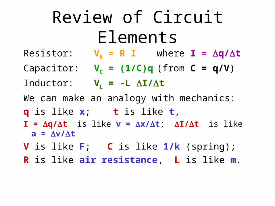
Resistor: VR = R I where I = q/t
Capacitor: VC = (1/C)q (from C = q/V)
Inductor: VL = -L I/t
We can make an analogy with mechanics:
q is like x; t is like t, I = q/t is like v = x/t; I/t is like a = v/t
V is like F; C is like 1/k (spring);
R is like air resistance, L is like m.
RL Circuit
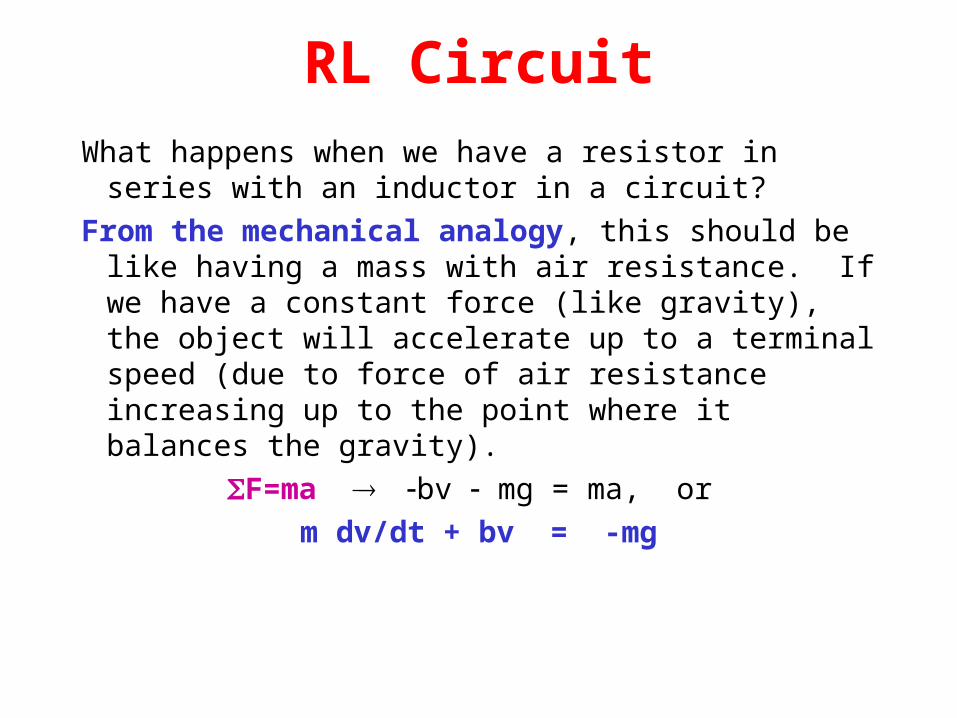
What happens when we have a resistor in series with an inductor in a circuit?
From the mechanical analogy, this should be like having a mass with air resistance. If we have a constant force (like gravity), the object will accelerate up to a terminal speed (due to force of air resistance increasing up to the point where it balances the gravity).
F=ma bv mg = ma, or
m dv/dt + bv = -mg
Mechanical Analogy: mass falling with air resistance
M a s s fal lin g w i th a ir re s is ta n c e
0
5 0
10 0
15 0
20 0
0
8.0
16.0
24.0
32.0
40.0
48.0
56.0
64.0
ti m e in se c o nd s
spe
ed
in
m/s

RL Circuit (cont.)
If we connect the resistor and the inductor to a battery and then turn the switch on, from the mechanical analogy we would expect the current (which is like velocity) to begin to increase until it reaches a constant amount.
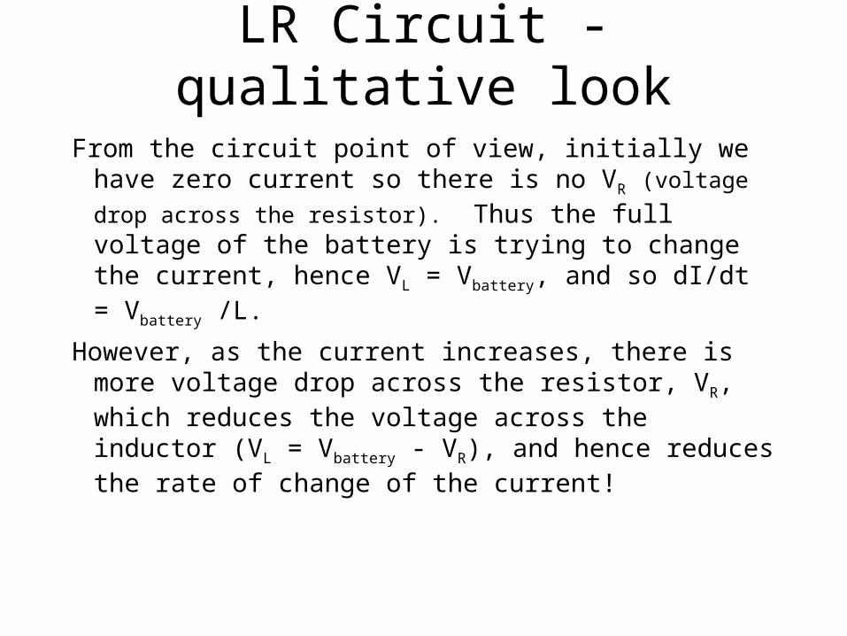
LR Circuit - qualitative look
From the circuit point of view, initially we have zero current so there is no VR (voltage drop across the
resistor). Thus the full voltage of the battery is trying to change the current, hence VL = Vbattery, and so dI/dt = Vbattery /L.
However, as the current increases, there is more voltage drop across the resistor, VR, which reduces the voltage across the inductor (VL = Vbattery - VR), and hence reduces the rate of change of the current!
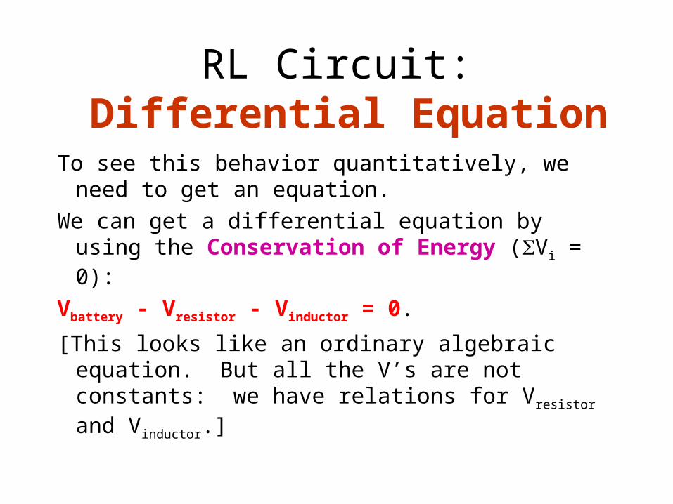
RL Circuit: Differential Equation
To see this behavior quantitatively, we need to get an equation.
We can get a differential equation by using the Conservation of Energy (Vi = 0):
Vbattery - Vresistor - Vinductor = 0.
[This looks like an ordinary algebraic equation. But all the V’s are not constants: we have relations for Vresistor and Vinductor.]

RL Circuit:Differential Equation
Vbattery - Vresistor - Vinductor = 0.
With Vbattery = constant, Vresistor = IR, and
Vinductor = L dI/dt, we have the differential equation (for I(t)):
Vbattery - IR - L dI/dt = 0. This can be rewritten as: IR + L dI/dt = Vbattery
which is an inhomogeneous first order differential equation, just like we had for the mechanical analogy:
m dv/dt + bv = -mg .

RL Circuit (cont.)
IR + L dI/dt = Vbattery
The homogeneous equation is: LdI/dt + RI = 0.
This has a dying exponential solution:
IH(t) = Io e-(R/L) t .
The inhomogeneous equation is:
L dI/dt + RI = Vbattery .
This has the simple solution: II(t) = Vbattery / R.
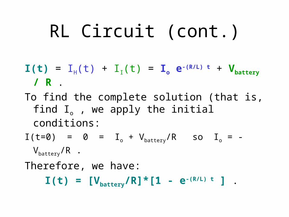
RL Circuit (cont.)
I(t) = IH(t) + II(t) = Io e-(R/L) t + Vbattery / R .
To find the complete solution (that is, find Io , we apply the initial conditions:
I(t=0) = 0 = Io + Vbattery/R so Io = -Vbattery/R .
Therefore, we have:
I(t) = [Vbattery/R]*[1 - e-(R/L) t ] .
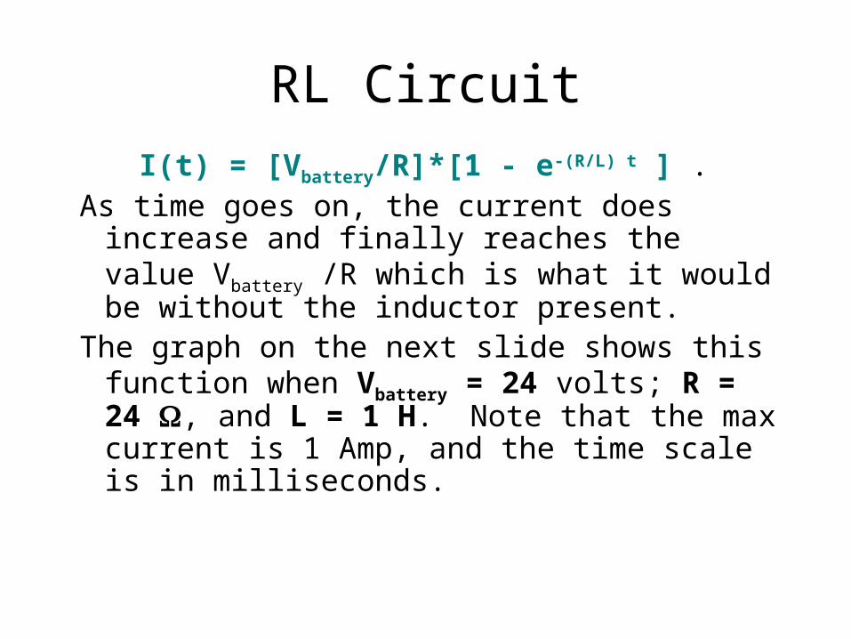
RL Circuit
I(t) = [Vbattery/R]*[1 - e-(R/L) t ] . As time goes on, the current does increase and
finally reaches the value Vbattery /R which is what it would be without the inductor present.
The graph on the next slide shows this function when Vbattery = 24 volts; R = 24 , and L = 1 H. Note that the max current is 1 Amp, and the time scale is in milliseconds.

RL Circuit: I(t) versus t
I(t) vs t for RL Circuit
00.20.40.60.81
1.21 6 11 16 21 26 31 36 41 46
t in milliseconds
I in
am
ps

Mechanical Analogy: mass falling with air resistance
M a s s fal lin g w i th a ir re s is ta n c e
0
5 0
10 0
15 0
20 0
0
8.0
16.0
24.0
32.0
40.0
48.0
56.0
64.0
ti m e in se c o nd s
spe
ed
in
m/s

RL Circuit
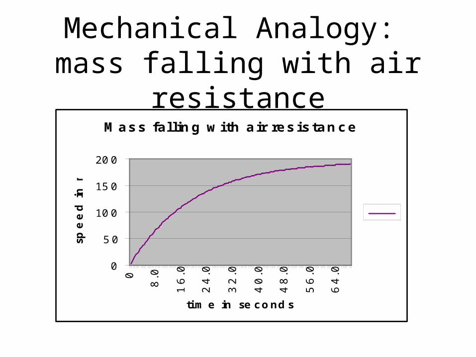
Note that this graph of I(t) versus t looks qualitatively just like v(t) versus t for the mass falling under constant gravity with air resistance. According to the analogy, the inductance acts like the mass, and the resistance acts like the coefficient for air resistance.
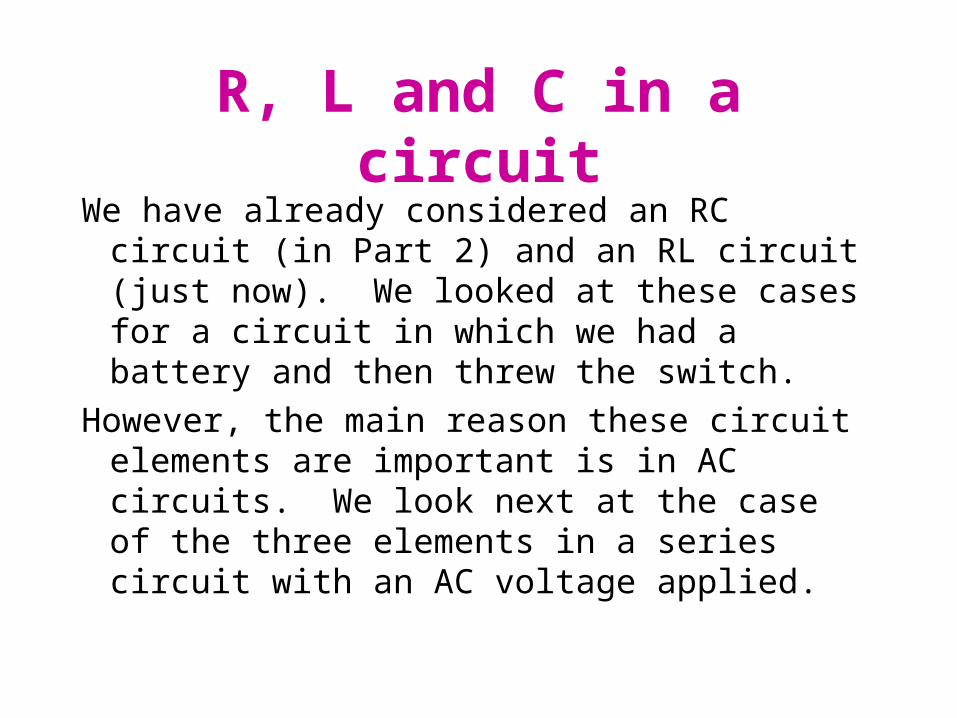
R, L and C in a circuit
We have already considered an RC circuit (in Part 2) and an RL circuit (just now). We looked at these cases for a circuit in which we had a battery and then threw the switch.
However, the main reason these circuit elements are important is in AC circuits. We look next at the case of the three elements in a series circuit with an AC voltage applied.

LRC Circuit: Oscillations
Newton’s Second Law: F = ma can be written as: F - ma = 0 . With a spring and resistance, this becomes: -kx -bv -ma = 0
This is like the equation we get from Conservation of Energy when we have a capacitor, resistor and inductor: V = 0 , or (1/C)Q + RI + L dI/dt = 0 ,
where VC = (1/C)Q, VR = RI, and
VL = L dI/dt.

Resonance
If we put an inductor and a capacitor with an AC voltage, we have the analogy with a mass connected to a spring that has an oscillating applied force.
In both of these cases (mechanical and electrical), we get resonance.
We’ll demonstrate this in class with a mass and spring.
This, it turns out, is the basis of tuning a radio!

LRC Circuit: Differential Equation
Starting with Conservation of Energy
(Vi = 0) and using VR = IR, VC = Q/C,
VL = LdI/dt , and applying a sine wave voltage (AC voltage), we get:
(1/C)Q + RI + LdI/dt = Vosin(t)
Putting this in terms of Q (I = dQ/dt):
(1/C)Q + RdQ/dt + Ld2Q/dt2 = Vosin(t)
we have a second order linear inhomo-geneous differential equation for Q(t).
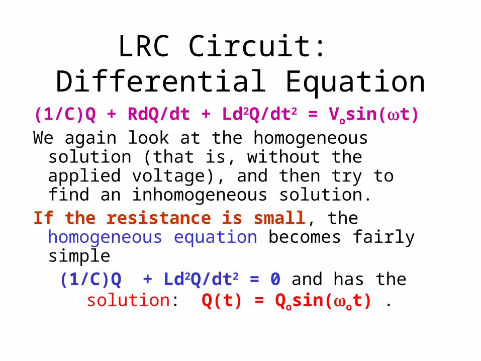
LRC Circuit: Differential Equation
(1/C)Q + RdQ/dt + Ld2Q/dt2 = Vosin(t)We again look at the homogeneous solution
(that is, without the applied voltage), and then try to find an inhomogeneous solution.
If the resistance is small, the homogeneous equation becomes fairly simple
(1/C)Q + Ld2Q/dt2 = 0 and has the solution: Q(t) = Qosin(ot) .
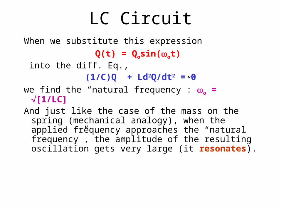
LC CircuitWhen we substitute this expression
Q(t) = Qosin(ot) into the diff. Eq.,
(1/C)Q + Ld2Q/dt2 = 0
we find the “natural frequency”: o = [1/LC]And just like the case of the mass on the spring
(mechanical analogy), when the applied frequency approaches the “natural frequency”, the amplitude of the resulting oscillation gets very large (it resonates).
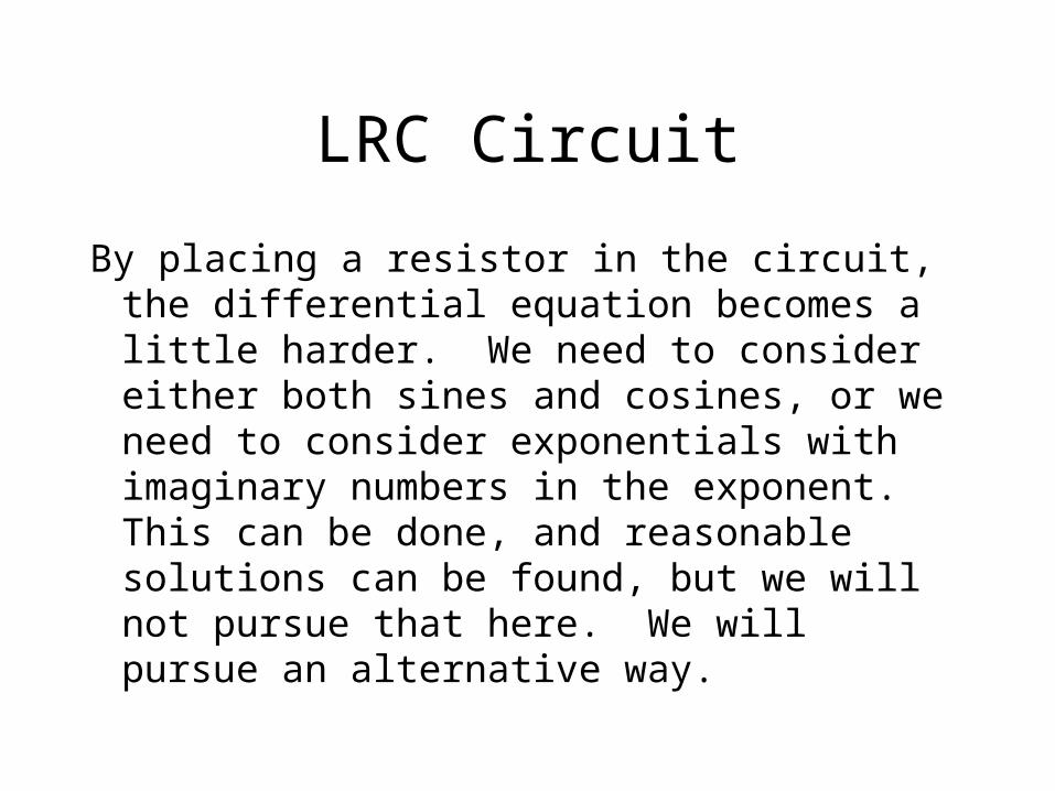
LRC Circuit
By placing a resistor in the circuit, the differential equation becomes a little harder. We need to consider either both sines and cosines, or we need to consider exponentials with imaginary numbers in the exponent. This can be done, and reasonable solutions can be found, but we will not pursue that here. We will pursue an alternative way.
LRC Circuit:Impedance
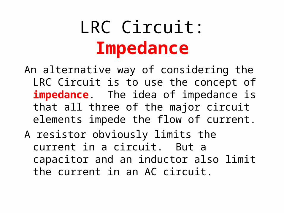
An alternative way of considering the LRC Circuit is to use the concept of impedance. The idea of impedance is that all three of the major circuit elements impede the flow of current.
A resistor obviously limits the current in a circuit. But a capacitor and an inductor also limit the current in an AC circuit.
LRC Circuit
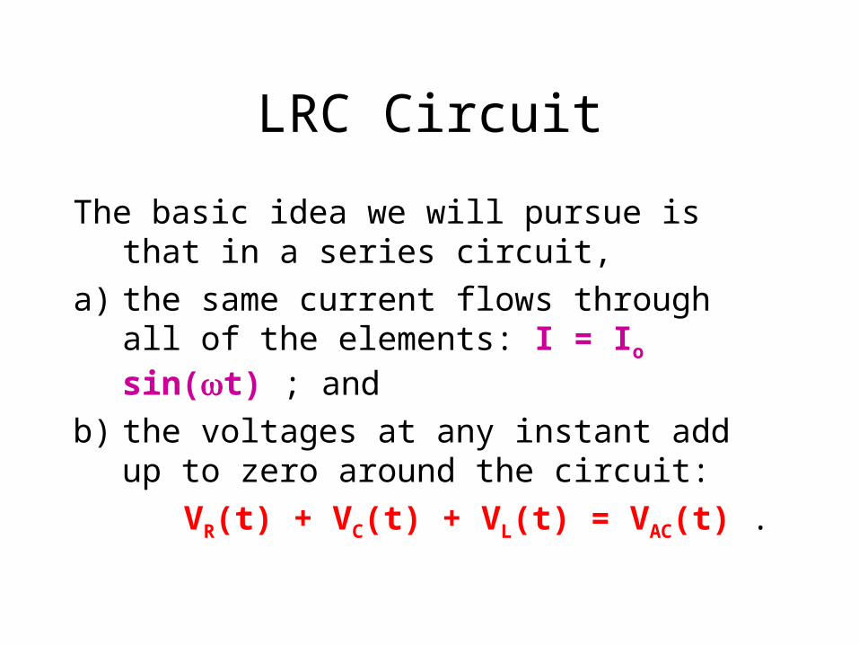
The basic idea we will pursue is that in a series circuit,
a) the same current flows through all of the elements: I = Io sin(t) ; and
b) the voltages at any instant add up to zero around the circuit:
VR(t) + VC(t) + VL(t) = VAC(t) .

Resistance
Because of Ohm’s law (VR = IR), we see that the current and the voltage due to the current are in phase (that is, when the oscillating voltage is at a maximum, the oscillating current is also at a maximum.
VR = Vro sin(t)
I = Io sin(t)
Vro = IoR

Capacitive ReactanceFor a capacitor: VC = (1/C)Q, and with I = dQ/dt, or Q = I dt, if I = Iosin(t), then
Q = (-Io/) cos(t), so VC = -(1/C)Iocos(t). Note that cosine is 90o different than sine - we say it
is 90o out of phase. This means that VC is 90o out of phase with the current!
Note that the constant (1/C) acts just like R. We call this the capacitive reactance,
XC = (1/C) .

Voltage across the capacitor
VC = -VCo cos(t)
I = Io sin(t)
VCo = IoXC where XC = 1/C

Inductive ReactanceFor an inductor, VL = L dI/dt, if I = Iosin(t),
then dI/dt = Io cos(t). Note that cosine is 90o different than sine - we say it is 90o out of phase. This means that VL is 90o out of phase with the current.
Since VL = L dI/dt, VL = LIo cos(t) , and we see that the constant L acts just like R. We call this the inductive reactance,
XL = L .
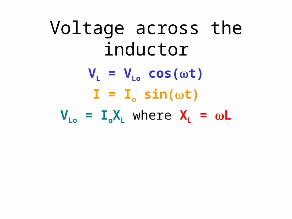
Voltage across the inductor
VL = VLo cos(t)
I = Io sin(t)
VLo = IoXL where XL = L
LRC in series
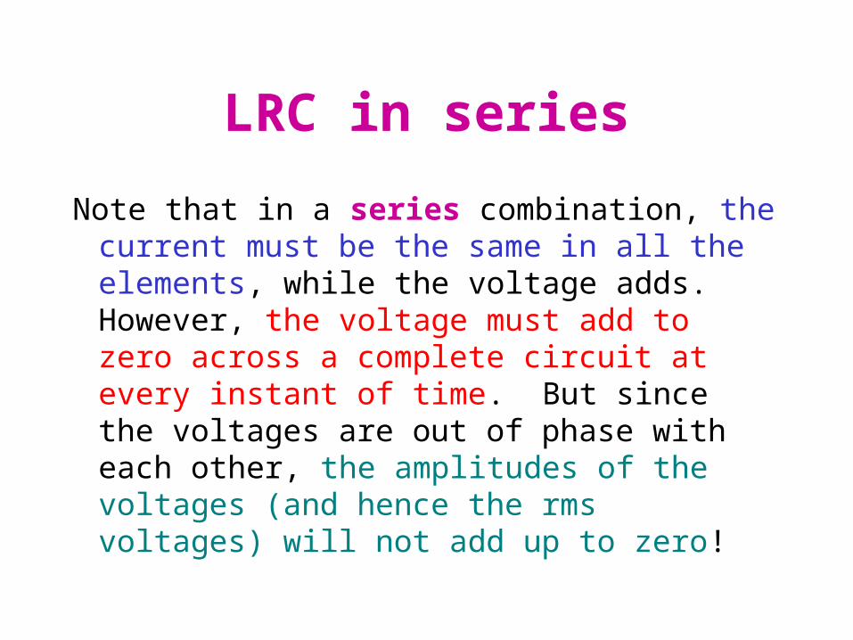
Note that in a series combination, the current must be the same in all the elements, while the voltage adds. However, the voltage must add to zero across a complete circuit at every instant of time. But since the voltages are out of phase with each other, the amplitudes of the voltages (and hence the rms voltages) will not add up to zero!
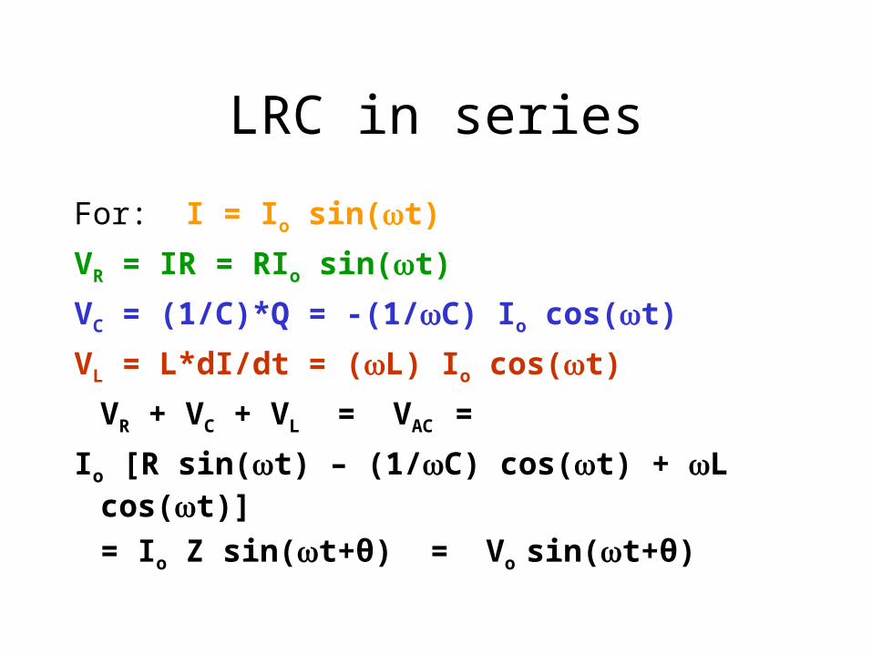
LRC in series
For: I = Io sin(t)
VR = IR = RIo sin(t)
VC = (1/C)*Q = -(1/C) Io cos(t)
VL = L*dI/dt = (L) Io cos(t)
VR + VC + VL = VAC =
Io [R sin(t) – (1/C) cos(t) + L cos(t)]
= Io Z sin(t+θ) = Vo sin(t+θ)
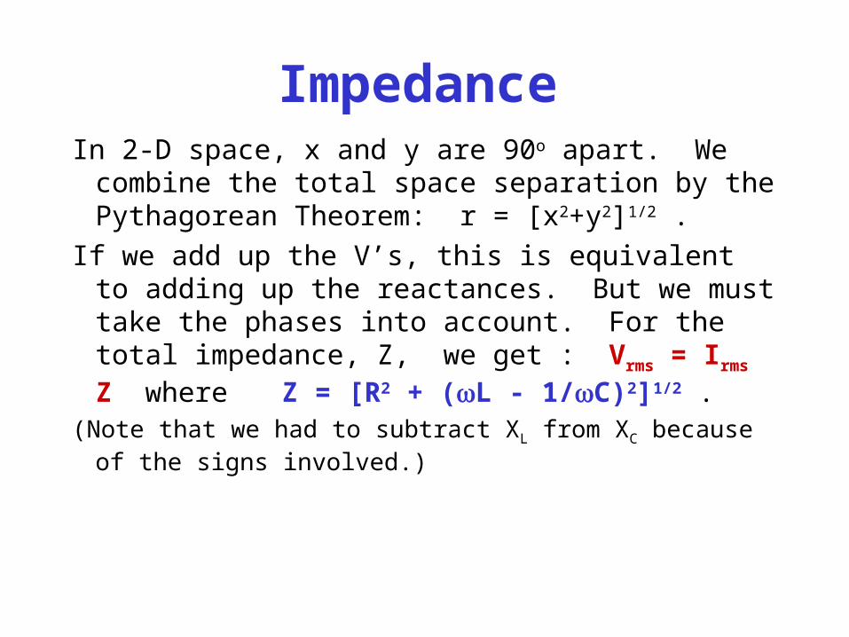
ImpedanceIn 2-D space, x and y are 90o apart. We combine
the total space separation by the Pythagorean Theorem: r = [x2+y2]1/2 .
If we add up the V’s, this is equivalent to adding up the reactances. But we must take the phases into account. For the total impedance, Z, we get : Vrms = Irms Z where Z = [R2 + (L - 1/C)2]1/2 .
(Note that we had to subtract XL from XC because of the signs involved.)

ResonanceVrms = IrmsZ where Z = [R2 + (L-1/C)2]1/2
Note that when (L - 1/C) = 0, Z is smallest and so I is biggest! This is the condition for resonance. Thus when LC]1/2, we have resonance. This is the same result we would get using the differential equation route.
Note that this is equivalent to the resonance of a spring when km]1/2
.
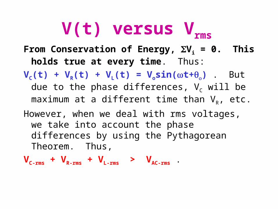
V(t) versus Vrms
From Conservation of Energy, Vi = 0. This holds true at every time. Thus:
VC(t) + VR(t) + VL(t) = Vosin(t+) . But due to the phase differences, VC will be maximum at a different time than VR, etc.
However, when we deal with rms voltages, we take into account the phase differences by using the Pythagorean Theorem. Thus,
VC-rms + VR-rms + VL-rms > VAC-rms .

Net Power Delivered
What about energy delivered?For a resistor, electrical energy is changed into heat, so the
resistor will remove power from the circuit.
For an inductor and a capacitor, the energy is merely stored for use later. Hence, the average power used is zero for both of these. Note that Power = I*V, but I and V are out of phase by 90o for both the inductor and capacitor, so on average there is zero power delivered.
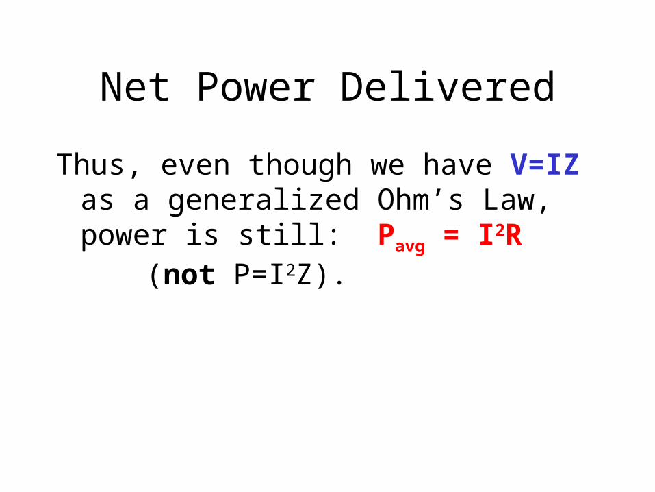
Net Power Delivered
Thus, even though we have V=IZ as a generalized Ohm’s Law, power is still: Pavg = I2R (not P=I2Z).

Computer Homework
There is a computer homework program on Inductance on Vol. 4, #4, that gives you practice on DC and AC behaviors of inductors.

Magnetism in Matter
Just as materials affect the electric fields in space, so do materials affect the magnetic fields in space.
Recall that we described the effect of materials on the electric fields with the dielectric constant, K. This measured the “stretchability” of the electric charges in the materials. This stretching due to applied electric fields caused electric fields itself.
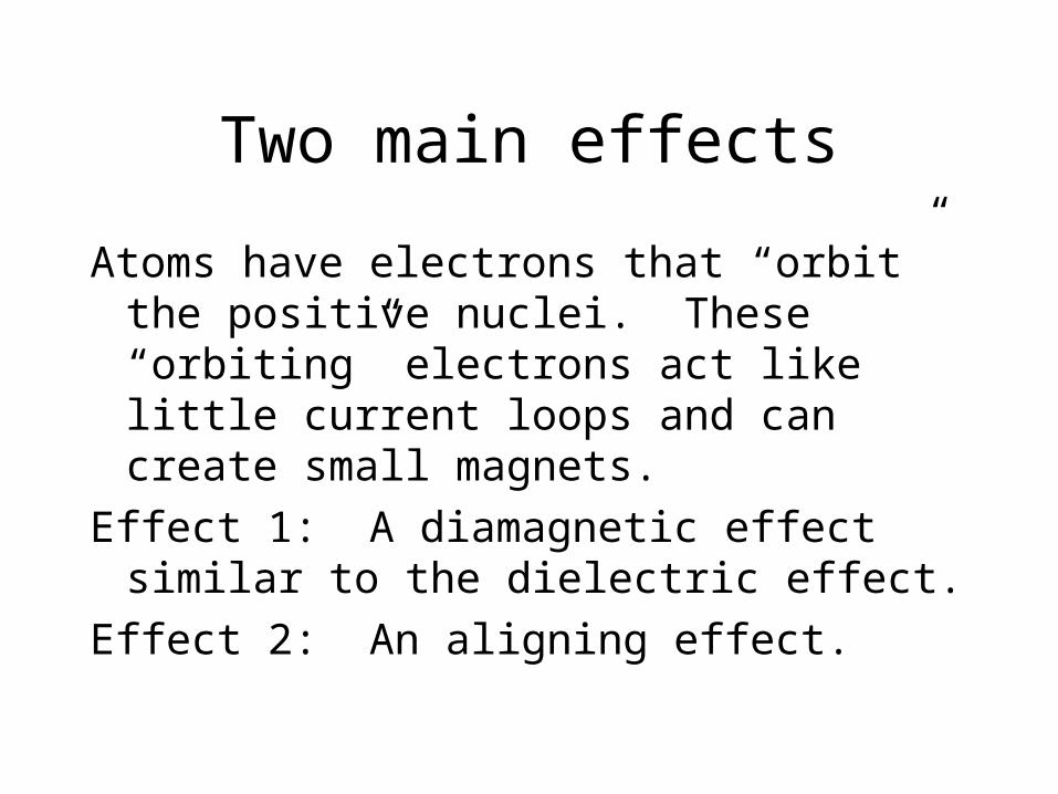
Two main effects
Atoms have electrons that “orbit” the positive nuclei. These “orbiting” electrons act like little current loops and can create small magnets.
Effect 1: A diamagnetic effect similar to the dielectric effect.
Effect 2: An aligning effect.
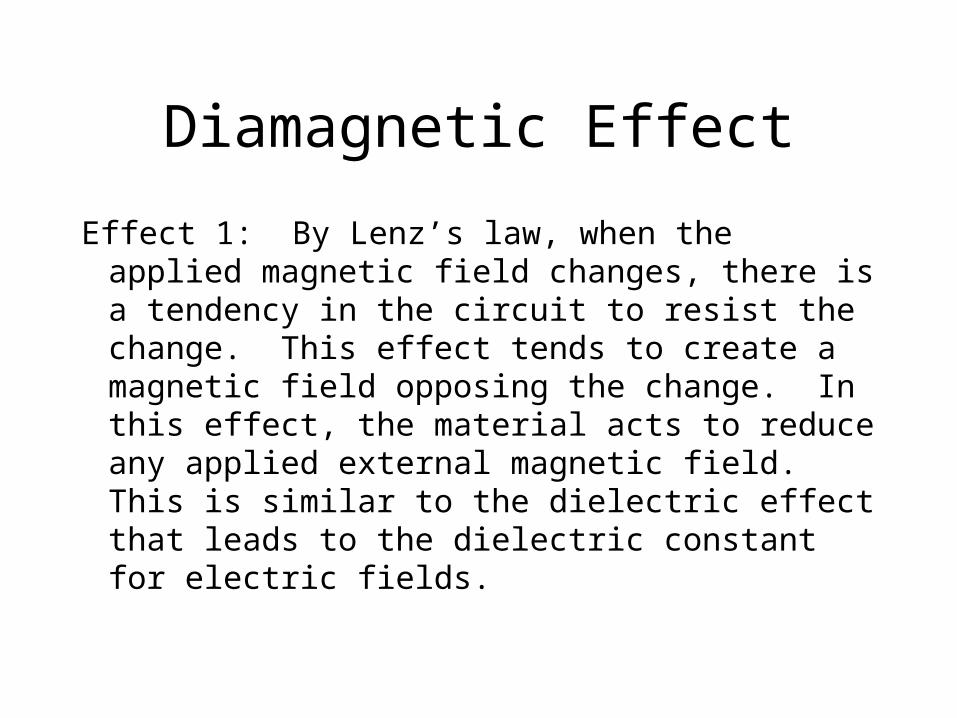
Diamagnetic Effect
Effect 1: By Lenz’s law, when the applied magnetic field changes, there is a tendency in the circuit to resist the change. This effect tends to create a magnetic field opposing the change. In this effect, the material acts to reduce any applied external magnetic field. This is similar to the dielectric effect that leads to the dielectric constant for electric fields.

Aligning Effect
Effect 2: Since the normal “currents” due to the “orbiting” electrons act like tiny magnets, these magnets will tend to align with an external magnetic field. This tendency to align will tend to add to any external applied magnetic field.
Heat tends to destroy this ordering tendency.
Net Result
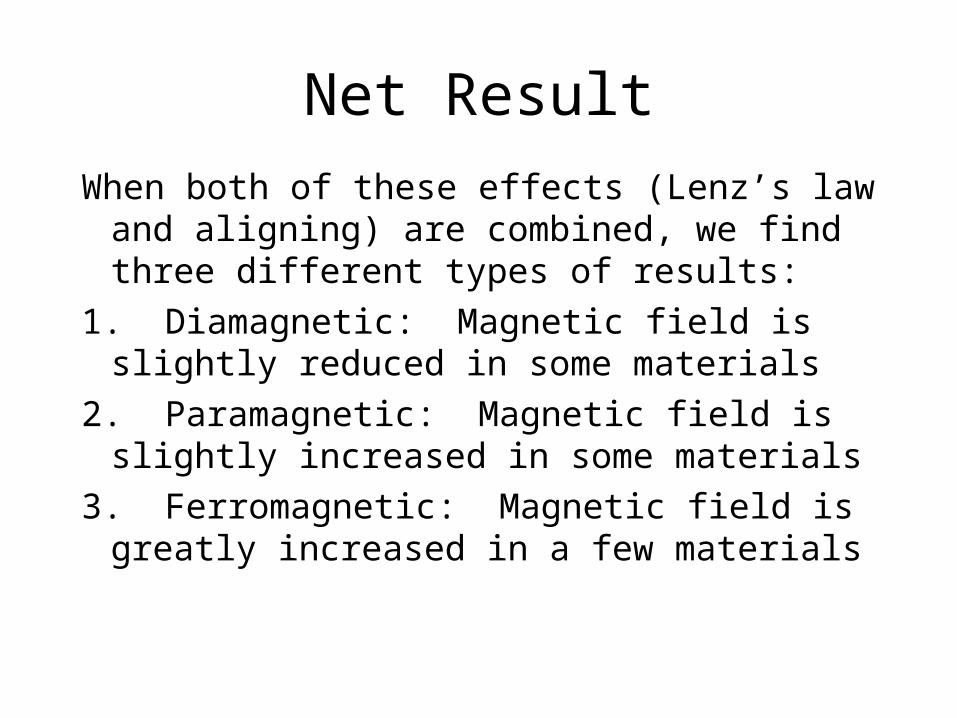
When both of these effects (Lenz’s law and aligning) are combined, we find three different types of results:
1. Diamagnetic: Magnetic field is slightly reduced in some materials
2. Paramagnetic: Magnetic field is slightly increased in some materials
3. Ferromagnetic: Magnetic field is greatly increased in a few materials

B, M and HWe are already familiar with B. It is called the
magnetic field or the magnetic flux density (from its use in V = -d/dt [BdA] ). This is the total field in space.
We have H, called the magnetic field strength or magnetic intensity. This is the field due to external currents only.
We have M, called the magnetization. It is the field due to the material only.

Magnetic Susceptibility andMagnetic permeability
To give a quantitative measure to the effects of materials on magnetic fields, and to relate B, M and H to one another, we define two additional quantities:
= magnetic permeability: B = H , and
o is the value of in vacuum)= magnetic susceptibility: M = H .
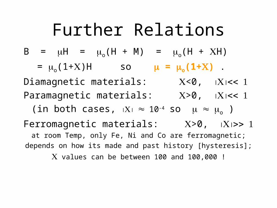
Further RelationsB = H = o(H + M) = o(H + H)
= o(1+)H so = o(1+) .
Diamagnetic materials: <0, Paramagnetic materials: >0,
(in both cases, 10-4 so o )
Ferromagnetic materials: >0, at room Temp, only Fe, Ni and Co are ferromagnetic;
depends on how its made and past history [hysteresis];
values can be between 100 and 100,000 !

Hysteresis
is not constant - it depends on history
hard - permanent soft -
magnet transformer
B B
H H