induction motors/generators9ff2c5bd-7… · both induction motors and generators, however for...
TRANSCRIPT

Edition
02/2020
Installation, Operating & Maintenance Instructions
Induction
Motors/Generators
Horizontal 449, S449, 500, 580, 880, SH400, SH450, SH560 Frames TEFC & TEAO Enclosures Types CZ, NCZ, CGZ, CMZ, NCMZ, 1LA3, 1LA4

Dear Valued Customer, Thank you for purchasing a Siemens motor. We value your choice and that’s why this product is developed with world class quality backed by over a century of industry leading innovation and reliable application experience.
We understand that electric motors play an important role in the way people live and experience life every day throughout the world. With this thought in mind, it is important to treat this driving machine in an appropriate way to help increase the best experience during storage, installation and operation.
Our team put a lot of effort into this manual to ensure that all of the information provided will help with your application. As a result, we hope that you will carefully read this manual before proceeding with the motor installation, operation or maintenance. This recommendation is based on the desire to see your motor operational experience reach the highest levels of safety and reliability. If you have questions about the information in this manual, we encourage you to reach out to your local Siemens representative for further assistance. For the best motor experience, we highly recommend that a copy of this manual stay close to the motor at all times so it can be referenced whenever necessary.
Again, we appreciate your choice to own a Siemens motor and value the opportunity to serve your application needs. Thank you from all of us at Siemens!
ANIM-03522-0814 A5E39660981A REV AD (Supersedes all previous issues of ANIM-03522) ©2020 Siemens Industry, Inc. All rights reserved.
Edition 02/2020
Introduction
Safety Information
Description
Preparation
Installation
Operation
Maintenance
Storage
Disposal
Spare Parts
Motor Service Record
Vibration Analysis Sheet
Notes
Induction
Motors/Generators
Horizontal 500, 580, 880, SH400, SH450, SH560 Frames TEFC & TEAO Enclosures
Types CZ, NCZ, CGZ, CMZ, NCMZ, 1LA3, 1LA4
Installation, Operating & Maintenance Instructions
ANIM-03522-0814 A5E39660981A REV AD (Supersedes all previous issues of ANIM-03522) ©2020 Siemens Industry, Inc. All rights reserved.
1
2
3
4
5
6
7
8
9
10
11
12
13

4 A5E39660981A REV AD
Note - These instructions do not purport to cover all details or variations in equipment, nor to provide for every possible contingency to be met in connection with installation, operation or maintenance. Should further information be desired, or should particular problems arise which are not covered sufficiently for the user’s purposes, the matter should be referred to:
1. Your local Siemens Sales Office. --Or-- 2. Siemens Technical Support Communication Center : Inside the U.S.: 1-800-333-7421 Outside the U.S.: +1-423-262-5710 Online: www.industry.usa.siemens.com/industry and click on Industry Services
The contents of this instruction manual shall not become part of or modify any prior or existing agreement, commitment or relationship. The sales contract contains the entire obligation of Siemens. The warranty contained in the contract between the parties is the sole warranty of Siemens. Any statements contained herein do not create new warranties or modify the existing warranty.
Siemens machines are built in accordance with the latest applicable revision of the National Electric Code, Underwriters Laboratories Standards and Procedures, and NEMA (National Electrical Manufacturers Association) Standards. These publications and this instruction manual should be thoroughly read and understood prior to beginning any work on this equipment.
The information contained within is intended to assist operating personnel by providing information on the general characteristics of the purchased equipment. It does not relieve the user of the responsibility of using accepted engineering practices in the installation, operation and maintenance of this equipment.
Should a conflict arise between the general information in this manual and the contents of the drawings and supplementary material, the latter shall take precedence.
The illustrations in this manual show typical machines. Special features may deviate from those pictured.
5 A5E39660981A REV AD
Table of Contents 1 Introduction ................................................................................................ 8
1.1 About these instructions ........................................................................ 8
1.2 Warranty ................................................................................................ 8
1.3 Checking Delivery .................................................................................. 8
2 Safety Information ........................................................................................ 9
2.1 Qualified Person ..................................................................................... 9
2.2 Safety Notices ........................................................................................ 9
2.3 General Information ............................................................................ 10
2.4 Hazardous Areas .................................................................................. 11
2.5 Protection Equipment .......................................................................... 11
2.6 Checking the Load Handling Attachments .......................................... 12
2.7 Lifting and Transportation ................................................................... 12
3 Description .................................................................................................. 13
3.1 Frame Sizes and Dimensions ............................................................... 13
3.2 Type Designations and Cooling Method .............................................. 13
3.3 Ventilation Description ........................................................................ 13
3.4 Applicable Industry Standards ............................................................. 14
4 Receiving .................................................................................................. 15
4.1 General Information ............................................................................ 15
4.2 Transport Markings .............................................................................. 15
4.3 Bearing Recommendations .................................................................. 16
4.4 Handling Recommendations ................................................................ 17
5 Installation .................................................................................................. 18
5.1 Location ............................................................................................... 18
5.2 Foundation ........................................................................................... 18
5.3 Preparation for Service ........................................................................ 19
5.4 Mounting ............................................................................................. 20
5.5 Selecting Mounting Bolts ..................................................................... 21
5.6 Tightening Torques and Securing Bolt Connections ............................ 22
5.7 Coupling of Sleeve Bearing Motors ...................................................... 23
5.8 Alignment ............................................................................................ 24
5.9 Hot Alignment...................................................................................... 27
5.10 Vibration .............................................................................................. 28
5.11 Doweling ............................................................................................. 28
5.12 Force Feed Lubrication ........................................................................ 29
5.13 Oil Mist Purge ...................................................................................... 29
6 A5E39660981A REV AD
5.14 External Wiring .................................................................................... 30
5.15 Direction of Rotation ........................................................................... 32
5.16 Intrinsically Safe .................................................................................. 33
5.17 Typical Motor Control Settings ............................................................ 34
6 Operation .................................................................................................. 36
6.1 Initial Start and Commissioning ........................................................... 36
6.2 Normal Operation ................................................................................ 39
6.3 Voltage/Frequency Variation ............................................................... 40
6.4 Troubleshooting ................................................................................... 41
7 Maintenance .............................................................................................. 44
7.1 Preventative Maintenance ................................................................... 44
7.2 Inspection ............................................................................................ 46
7.3 Corrective Maintenance ....................................................................... 49
7.4 Cleaning - Rotor ................................................................................... 49
7.5 Cleaning - Stator .................................................................................. 50
7.6 Cleaning – Bearing and Housing .......................................................... 50
7.7 Testing – Insulation Resistance and Polarization Index ....................... 50
7.8 Drying Stator Insulation ....................................................................... 53
7.9 Bearing – General Maintenance .......................................................... 55
7.10 Bearing – Lubrication........................................................................... 59
7.11 Bearing - Replacement ......................................................................... 62
7.12 Paint Maintenance ............................................................................... 68
7.13 Anti-condensation Space Heater Replacement ................................... 69
8 Storage .................................................................................................. 70
8.1 General Information ............................................................................ 70
8.2 Long-Term Storage .............................................................................. 71
8.3 Preparation for Storage ....................................................................... 73
8.4 Storage Maintenance ........................................................................... 74
8.5 Preparation for Service ........................................................................ 76
9 Disposal .................................................................................................. 77
9.1 RoHS – Restricting the use of certain Hazardous Substances .............. 77
9.2 Dismantling the Machine ..................................................................... 77
9.3 Disposal of Material ............................................................................. 78
10 Spare Parts .............................................................................................. 79
11 Motor Service Record ................................................................................ 87
12 Vibration Analysis Sheet ........................................................................... 88
13 Notes .................................................................................................. 89

7 A5E39660981A REV AD

8 A5E39660981A REV AD
1 Introduction 1 Siemens electrical motors and generators are designed for driving rotating equipment in industrial environments and for energy conversion. These machines are characterized by a high level of safety, long lifetime and overall reliability backed by over a century of industry leading quality and innovation. Please review this document to ensure the optimal motor operational experience. It is important to understand each unique motor and how it was designed to meet the given application.
1.1 About these instructions
These instructions describe the machine and explain how to handle it, from initial delivery to final disposal of the equipment. These instructions apply to both induction motors and generators, however for clarity reasons, the manual will refer the machine as a “motor” or “machine”. Read these operating instructions before you handle the machine and follow the instructions to become familiar with its design and operating principles and thus ensure safe, problem-free machine operation and long service life. Please contact the Service Center if you have any suggestions on how to improve this document.
1.2 Warranty
These instructions present general recommendations for installation, operation and maintenance of induction motors built at Siemens Norwood. If additional information is required, please contact Siemens. Review your sales contract for warranty coverage. Documentation of storage, maintenance, power quality, alignment and re-greasing (lubrication) may be required for certain warranty considerations.
1.3 Checking Delivery
The components are assembled on an individual basis. Upon receipt of the delivery, please check whether the scope of the delivery matches the accompanying documents. Immediately report all apparent: - Transport damage to the delivery agent. - Defects/missing components to your contract partner.
These operating instructions are part of the scope of delivery; keep them in a location where they can be easily accessed.
9 A5E39660981A REV AD
2 Safety Information 2 This equipment contains hazardous voltages. Death, serious personal injury or property damage can result if the safety instructions are not followed. The successful and safe operation of motors and generators is dependent upon proper handling, installation, operation and maintenance. Failure to follow certain fundamental installation and maintenance requirements may lead to personal injury and the failure and loss of the motor as well as damage to other property. Only qualified personnel should work on or around this equipment after becoming thoroughly familiar with all warnings, safety notices and maintenance procedures contained herein. Only qualified personnel should be involved in the inspection, installation, maintenance and repair procedures while ensuring all plant safety procedures are observed.
2.1 Qualified Person
For the purpose of this manual and product labels, a Qualified Person is one who is familiar with the installation, construction and operation of the equipment, and the hazards involved. In addition, he or she has the following qualifications:
1. Is trained and authorized to energize, de-energize, clear, ground and tag circuits and equipment in accordance with established safety practices.
2. Is trained in the proper care and use of protective equipment, such as rubber gloves, hard hat, safety glasses, face shields, flash clothing, etc., in accordance with established safety practices.
3. Is trained in rendering first aid.
2.2 Safety Notices
Danger: For the purpose of this manual and product labels, Danger indicates an imminently hazardous situation which, if not avoided, will result in death or serious injury. Warning: For the purpose of this manual and product labels, Warning indicates a potentially hazardous situation which, if not avoided, may result in minor or moderate injury. Caution: For the purpose of this manual and product labels, Caution indicates a potentially hazardous situation which, if not avoided, may result in minor or moderate injury. It is also used to alert against unsafe practices.

10 A5E39660981A REV AD
2.3 General Information
Motors and generators should be installed and grounded per all local and national codes and regulation. Do not operate this equipment in excess of the values given on nameplate or contrary to the instructions contained in this manual. The equipment (or a prototype) has been factory tested and found satisfactory for the condition for which it was sold. Operating in excess of these conditions can cause stresses and strains beyond design limitations. Failure to heed this warning may result in equipment damage and possible personal injury.
DANGER Hazardous voltage. Will cause death, serious injury, electrocution or property damage. Disconnect all power before working on this equipment.
CAUTION
Noise emissions. During operation, the machine's noise emission levels can exceed those permitted at the workplace, which can cause hearing damage.
Take steps to reduce noise, such as introducing covers and protective insulation or adopting hearing protection measures, so that the machine can be operated safely within your system.
NOTE Supply system switching.
Damage to the machine may be caused when switching to another supply system with different phasing.
The phasing must be synchronized during switching. Use appropriate means to synchronize the phasing.
NOTE System resonances.
Excessive vibrations and system resonances can damage the machine set.
Configure and match the system consisting of the foundation and machine set in such a way that no system resonances can arise and result in the permissible vibration levels being exceeded.
The vibration limit values according to applicable industry standards as shown on the motor control settings must not be exceeded.

11 A5E39660981A REV AD
2.4 Hazardous Areas
Electrical systems in hazardous areas must be assembled, installed, and operated by the applicable responsible persons in accordance with the applicable rules and regulations For products designed to be used in a classified hazardous area, Siemens indicates the intended hazardous area types both on permanently mounted nameplates and on the product's data sheet. Before installing this product in a classified hazardous area, refer to one of these sources to confirm that it has been designed for the specific conditions of the area.
WARNING Explosion or fire.
Can cause death, serious injury or property damage.
Do not modify or change any motor accessories, which are not suitable for the hazardous area classification. If part replacements are accurate duplicates of the original, then the hazardous area classification is maintained. Consult the factory for replacement parts and possible repair processes.
NOTE If heated accessories (i.e. anti-condensation heaters or oil sump heaters) are to be replaced or newly installed on equipment marked for service in a hazardous area, ensure that the heater’s surface temperature will not exceed the area's safe temperature limit
2.5 Protection Equipment
If pre-installed instruments such as temperature or vibration sensors are provided, ensure that a circuit is in place to monitor these sensors and activate alarm or trip conditions as appropriate.

12 A5E39660981A REV AD
2.6 Checking the Load Handling Attachments
Inspect the load handling attachments such as the load stands, lifting eyes, ring bolts and the lifting gear. Before lifting the machine: - Inspect the load handling attachments on the machine for possible
damage. Replace any load handling attachments that are found to be damaged.
- Ensure the load handling attachments are correctly secured. - When lifting the machine, use only approved and undamaged lifting gear
of sufficient rated capacity (5x safety factor). Check prior to use.
WARNING The machine can be dropped
If the load handling attachments and lifting gear are damaged or not correctly secured, the machine may be dropped during lifting. This can result in death, serious injury or material damage. Inspect the load handling attachments and lifting gear before use.
2.7 Lifting and Transportation
- Persons driving cranes and fork-lift trucks must hold appropriate licenses.
- If the motor is packed and depending on the weight, size and on-site conditions, lift crates and transport frames using a fork-lift truck or a crane with slings. The crane or fork-lift truck must be suitable for the load.
- When lifting the machine, use only approved and undamaged sling guides and spreaders of sufficient rated capacity and appropriate type. Check prior to use. The approximate weight of the machine is shown on the outline drawing.
- Do not exceed the following maximum lifting acceleration and lifting speed:
• Acceleration a ≤ 0.4 g (≈ 4 m/s2) • Velocity v ≤ 20 m/min
- When lifting, always ensure the rotor is blocked and use only the load handling attachments on the stator housing, such as load stands, eye bolts or lifting eyes on the bearing shield.

13 A5E39660981A REV AD
3 Description 3 3.1 Frame Sizes and Dimensions
For motors built in the frame sizes covered by this manual, the letter dimensions have the same definitions as established by NEMA or IEC Standards. Established dimensions for these frames may be found on catalog sheets, certified dimension prints or motor outline drawings.
3.2 Type Designations and Cooling Method
The motor type designation consists of a basic letter or letters indicating the motor enclosure type to which other letters may be added denoting modifications. Refer to the following table.
Cooling Method
Cooling Description
NEMA Enclosure
Enclosure Description
Type Designation
IC411
Rib-cooled, self-ventilated, IP55 Enclosed, protected against dust and jet-water
TEFC Totally Enclosed
Fan Cooled
CZ, NCZ, CMZ, NCMZ,
CGZ, 1LA, 1NS*
IC416
Rib-cooled, force-ventilated, IP55 Enclosed, protected against dust and jet-water
TEAO Totally Enclosed
Air Over
CZAO, CMZAO, CGZAO,
1LA, 1NS*
*The 1NS designation is a frame specific totally enclosed motor suitable for hazardous areas. Siemens offers enclosure modifications for special applications. An additional letter may appended to the end of the type designation.
3.3 Ventilation Description
TEFC Enclosure
The motor is constructed with an internal and external airflow circuit. The internal airflow is driven by a shaft-mounted fan which recirculates air through the stator and rotor cores and transfers heat from the internal components to the fin equipped enclosure. The external airflow is driven with a shaft-mounted fan which forces ambient air through the enclosure fins to cool the machine.

14 A5E39660981A REV AD
TEAO Enclosure
The motor is constructed with an internal and external airflow circuit. The internal airflow is driven by a shaft-mounted fan which recirculates air through the stator and rotor cores and transfers heat from the internal components to the fin equipped enclosure. The external airflow is driven with a separate auxiliary-powered blower fan which forces ambient air through the enclosure fins to cool the machine.
3.4 Applicable Industry Standards
The following standards are referred to for a portion or the entire finished product. For date references, only the edition cited applies. For undated references, the latest edition of the referenced document applies (including any amendments).
Standard Title NEMA MG-1 Motors and Generators
IEEE 112 IEEE Standard Test Procedure for Polyphase Induction Motors and Generators
IEEE 43 IEEE Recommended Practice for Testing Insulation Resistance of Electric Machinery
IEEE 522 IEEE Guide for Testing Turn Insulation of Form-Wound Stator Coils for Alternating-Current Electric Machines
NEMA 250-2008 Enclosures for Electrical Equipment (1000 Volts Maximum) IEC 60034 Rotating Electrical Machines
CAN/CSA-C22.2 No. 0 General Requirements – Canadian Electrical Code, Part II CAN/CSA-C22.2 No. 100-14 Motors and Generators UL Std. No.1004-1 (Ed. 2) Rotating Electrical Machines – Hazardous Locations CAN/CSA-C22.2 No. 145 Electric Motors and Generators for Use in Hazardous (Classified)
Locations (Guidance Only) CAN/CSA-C22.2 No. 213- M1987
Non-Incendive Electrical Equipment for Use in Class I, Division 1 and 2 Hazardous (Classified) Locations
UL 1604 (Ed. 3) Electrical Equipment for Use in Class I and II, Division 2; Class III Hazardous Locations
UL 674 (Ed. 4) Electrical Motors and Generators for Use in Division 1, Hazardous (Classified) Locations (Guidance Only)
NFPA 70-12 US National Electric Code UL 1836 (Issue N.5) Outline of Investigation for Electric Motors and Generators for Use
in Class I, Division 2 and Class II, Division 2 Hazardous (Classified) Locations (Guidance Only)
API 541 4th Edition Introduction to API Standard 541-Form-Wound Squirrel Cage Induction Motors – Larger than 500 Horsepower
API 541 5th Edition Form-Wound Squirrel Cage Induction Motors – 500 Horsepower and Larger
API 547 2nd Edition General Purpose Form-Wound Squirrel Cage Induction Motors – 185 kW (250 HP) through 2240 kW (3000 HP)
15 A5E39660981A REV AD
4 Receiving 4 4.1 General Information
Motors are shipped in first class condition. The machines have been inspected and are skidded or boxed to prevent damage from ordinary handling during shipment. Inspect new motors for the shipping invoice. Make the examination before removing the machine from cars or trucks. If damage or indication of rough handling is evident, file a claim with the carrier at once, and notify your Siemens sales representative. Remove only the shipping invoice. Do not remove tags pertaining to lubrication, operation and storage instructions. Read and follow all instructions to ensure that no damage to the motor bearings (due to condensation) and motor windings occurs during storage. Use care in handling. Dropping the motor or otherwise imposing shock loads can cause unseen and undetected damage to bearings. This damage such as false brinelling of the races of anti-friction bearings can result in early bearing failure. If supplied, energize space heaters to help prevent condensation within the motor enclosure.
NOTE When product is received note product condition. If damage is noted, document and photograph all damage. Immediately notify transportation company, insurance company, and Siemens.
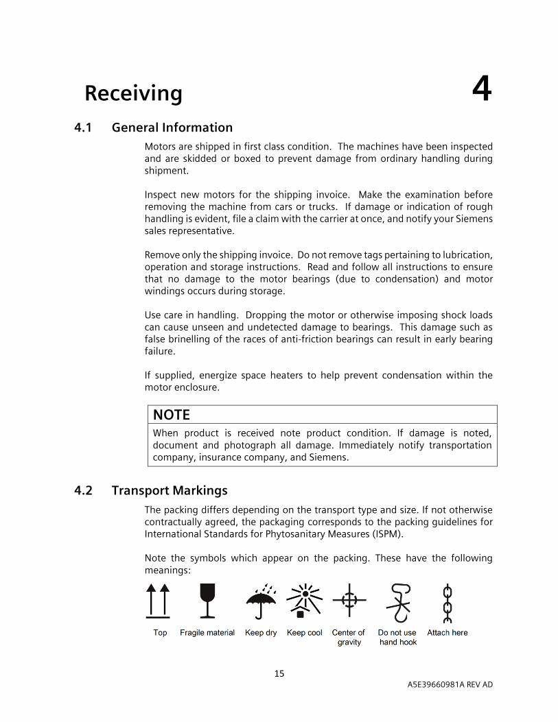
4.2 Transport Markings
The packing differs depending on the transport type and size. If not otherwise contractually agreed, the packaging corresponds to the packing guidelines for International Standards for Phytosanitary Measures (ISPM). Note the symbols which appear on the packing. These have the following meanings:

16 A5E39660981A REV AD
4.3 Bearing Recommendations Motors with sleeve bearings or oil lubricated antifriction bearings are shipped WITHOUT OIL in the bearing reservoir. These bearings and journal surfaces are protected during shipment by a temporary film of rust inhibiting oil or, when a motor is supplied specifically with “provisions for oil mist lubrication” (oil supply system furnished by the user), the motor is shipped from the factory with grease in the bearings.
When Receiving a Motor with Sleeve Bearings:
1. Remove shaft blocking materials after the motor is moved into installation location.
2. Visually inspect the bearing condition through the sight glass and bearing drain opening.
3. Check for moisture accumulation. Remove any traces of oxidation before putting the motor into service.
4. Fill bearing reservoirs to normal level with a high-grade industrial lubricating oil. See Maintenance Section of this instruction manual and the motor outline drawing to determine the proper oil type and level.
5. The motor shaft should be manually rotated by hand at approximately 30 rpm for 15 seconds. Ensure the oil rings in each bearing rotate freely.
When Receiving a Motor with Grease Lubricated Anti-Friction Bearings:
Motors equipped with grease lubricated antifriction bearings are shipped with the bearings already lubricated and ready for operation.
If the elapsed time from shipment to the time in which the unit is to be started is in excess of thirty (30) days, re-grease the bearings per the lubrication plate mounted on the motor.
When Receiving a Motor with Oil Mist Lubricated Anti-Friction Bearings:
1. Be sure that the motor is not stored outdoors. 2. Be sure that the oil mist lubrication is connected and operating before
starting the motor. 3. The oil mist lubrication should be in operation within two weeks after the
motor is received from the factory.
When Receiving a Motor with “Provisions for Oil Mist Lubrication”:
1. Leave the grease in the bearings if the motor is to be stored. 2. Before operating the motor with oil mist lubrication, disassemble the motor,
and clean the grease from bearings, end caps, and the bearing housing cavities with a suitable solvent.

17 A5E39660981A REV AD
4.4 Handling Recommendations Lifting devices are provided for handling only. An experienced rigger should be used to install motors. To avoid damage, the use of spreader bars is recommended on other than single point lifts. Lifting devices are provided to facilitate handling with shackles and cables. Avoid pounding or bumping the shaft, coupling or bearing parts, as shocks may damage bearings. Refer to motor outline for lifting point locations NOTE WEIGHT BEFORE LIFTING. For reference a weight range is shown on the table below, however, refer to the outline drawing for an actual approximate weight.
Approximate Motor Weight Ranges (Pounds / Kilograms) Frame Size Minimum Maximum
449 2060 / 934 2400 / 1089 S449 2750 / 1247 3000 / 1361 500 3,300 / 1,497 5,300 / 2,404 580 4,600 / 2,087 6,700 / 3,039 880 15,800 / 7,167 19,700 / 8,936
SH400 6,750 / 3,061 9,900 / 4,491 SH450 11,500 / 5,216 13,700 / 6,214 SH560 18,078 / 8,200 22,267 / 10,100
Apply tension gradually to cables. Do not jerk or attempt to move the unit suddenly. Do not exceed the following maximum lifting acceleration and lifting speed:
• Acceleration a ≤ 0.4 g (≈ 4 m/s2) • Velocity v ≤ 20 m/min
WARNING
Heavy equipment.
Improper handling may cause death, serious injury or property damage.
Check lifting devices before lifting. Use proper slings, chains and spreaders.
NOTE Always take account of the center of gravity when transporting or lifting the motor. The motor’s center of gravity is indicated on the motor outline along with other special lifting and handling instructions.

18 A5E39660981A REV AD
5 Installation 5 5.1 Location
Select the location for the motor and driven equipment that will: 1. Be clean, dry, well ventilated, properly drained, and provide accessibility for
inspection, lubrication and maintenance. Outdoor installations may require protection from the elements.
2. Provide adequate space for motor removal without shifting the driven unit. 3. Not exceed ambient temperature as shown on the motor nameplate. 4. Permit the motor to safely deliver adequate power. The temperature rise of
the standard motor is based on operation at an altitude not higher than 3,300 feet above sea level.
5. Avoid condensation of moisture in bearings and on windings. Motors should not be stored or operated in areas subject to rapid temperature changes unless motors are energized or protected with space heaters.
CAUTION
Damp Locations
Can cause motor damage if equipment is operating intermittently.
Use space heaters to prevent dampness. Grease machine fits when the unit is reassembled to prevent corrosion.
5.2 Foundation The foundation and motor mounting plate (adapter or soleplates) shall be sufficiently stiff to ensure that the static deflection of the installed unit is less than 0.002 inches [0.051 mm] under any foot relative to the simulated datum plane formed by the four motor feet. Additionally, the foundation and motor mounting plate (adapter or soleplates) system shall be free of excitable structural system resonances within common motor forcing frequencies (1xRPM, 1xLF, etc.). Concrete (reinforced as required) makes the best foundation, particularly for large motors and driven units. It may be located on soil, structural steel, or building floors provided the total weight (motor, driven unit, foundation) does not exceed the allowable bearing load of the support. Allowable bearing loads of structural steel and floors can be obtained from engineering handbooks. Building codes of local communities provide the recommended allowable bearing loads for different types of soil. For rough approximation, the foundation should be approximately 2-1/2 times the total weight of the motor.

19 A5E39660981A REV AD
Before pouring, locate foundation bolts by use of template frame and provide secure anchorage (not rigid). It is recommended that a fabricated steel base be used between motor feet and foundation. See certified drawings of motor, base, and driven unit for exact location of foundation bolts. Allow for grouting base when pouring. Cast the base foot-pads level and in the same plane.
5.3 Preparation for Service
Inspect the Machine
The interior and exterior of the motor should be free of spilled oil, water, dust, dirt or other environmental contaminants. If necessary, the exterior should be wiped clean, and the interior blown out with compressed air at a reduced pressure.
WARNING Moisture
Can cause damage to the stator windings and bearings.
Protect the motor from moisture.
Remove Anti-Corrosion Protection
Machined, bare metal surfaces of machine parts and small components such as screws, bolts, wedges, feather keys, and dowel pins, are treated with an anti-corrosion agent.
Use petroleum, petroleum ether or a similar solvent or detergent to remove the anti-corrosion coating from the machined surfaces of machined parts and from small components, such as the motor feet, shaft extension, accelerometer surfaces or ground pads. Do not sand or scrape off the protective coating with an abrasive pad or metal tool. For bolt threads, tapered pins, and fastening parts, remove the anti-corrosion agent by chasing the threads or wiping down the part. After carefully removing the anti-corrosion agent, immediately start the installation work.
WARNING Solvents
May explode. This can result in death, serious injury or property damage.
Prevent any open flames or sparks. Dispose of rags and supplies appropriately.
NOTE
Paintwork damage.
Make sure that the detergent or solvent does not come into contact with any painted surfaces, as this could damage the paint.

20 A5E39660981A REV AD
Inspect and Re-lubricate Bearings
Ensure that the bearings and lubricant cavities are free of dust and dirt and that the (oil) plugs in the cavity are sealed and tight. Scratches or rust on the shaft journals must be carefully removed. Use the specified or compatible grease or the specified viscosity turbine oil as applicable. Refer to the lubrication plate(s) on the motor, certified outline drawing and the instruction manual.
5.4 Mounting Prior to mounting the machine, ensure the mating faces are clean and all anti-corrosion protection has been removed. Mount the motor base (if used) on the foundation or other support. Shim as required to level. Use a laser or spirit level (check two directions at 90°) to ensure the motor feet will be in one plane (base is not warped) when base bolts are tightened. Set the motor on the base, install nuts and lightly tighten. DO NOT FULLY TIGHTEN UNTIL AFTER ALIGNMENT. Once the motor has been aligned, shimmed, and fastened to the base, it is recommended that a “soft foot” check be performed for each of the motor foot with the use of a dial indicator or laser alignment tool.
NOTE
Experience has shown that any base-mounted assemblies of motor and driven units temporarily aligned at the factory may twist during shipment. Therefore, alignment must be checked after mounting. Realignment is to be documented for warranty information.
Shaft Extensions with a Step Key
To maintain the balancing quality, you have the following options: • If the transmission element is shorter than the step key, then the section
of the step key protruding from the shaft contour and transmission element must be machined in order to maintain the balance quality.
• If the transmission element is drawn up on to the shoulder of the shaft, ensure that the part of the coupling groove where the step key is not inserted is taken into consideration when balancing the coupling.
The following applies for all 2-pole machines and 4-pole machines with a frequency ≥ 60 Hz:
• The step key must be shortened if the coupling hub is shorter than the step key.
• The center of gravity of the coupling half should be within the length of the shaft end.

21 A5E39660981A REV AD
• The coupling used must be prepared for system balancing. The number of poles of the machine is specified on the rating plate (in the designation of the motor type).
WARNING
The step key can fall out.
The step keys are only locked against falling out during shipping. If a machine with two shaft extensions does not have an output element on one shaft extension, the feather key can fall out during operation.
Death or serious injury can result.
1. Do not operate the machine unless the transmission elements have been verified to be secure and not loose.
2. On shaft extensions without output element, ensure that the step key cannot fall out and shorten it by approximately half.
NOTE
Improper handling.
Mounting parts such as temperature sensors or speed sensors are attached to the machine and could be ripped off or destroyed as a result of improper handling. This could lead to machine malfunctions, extending even to total loss of the machine.
1. Where necessary, use suitable steps when performing installation work on the machine.
2. Do not stand on cables or attachments during installation. Do not use attachments as steps.
5.5 Selecting Mounting Bolts Unless specified otherwise, use fixing bolts with at least strength grade 5 in accordance with ANSI B18.6.3 or class 8.8 in accordance to ISO 898-1 to ensure that the machine is securely mounted and to transmit the torque-generated forces.
When selecting bolts (or screws) and designing the foundation, bear in mind the maximum forces occurring in the event of a fault, such as short circuits. Force values for the foundation loading can be found on the documentation provided.
Refer to the following table for recommended bolt sizes per frame size.
Motor Frame Size Bolt Size Tightening Torque (+/-10%) 449/S449 0.75-10 UNC 260 ft-lbs / 353 N-m
500 0.75-10 UNC 260 ft-lbs / 353 N-m 580 0.75-10 UNC 260 ft-lbs / 353 N-m 880 1.125-7 UNC 1940 ft-lbs / 2630 N-m
SH400 1.125-7 UNC 900 ft-lbs / 1220 N-m SH450 1.5-6 UNC 1940 ft-lbs / 2630 N-m SH560 M36 1510 ft-lbs / 2047 N-m

22 A5E39660981A REV AD
5.6 Tightening Torques and Securing Bolt Connections
Bolt Locking Devices
Refit nuts or bolts that are mounted together with locking, resilient, and/or force-distributing elements with identical, fully functional elements re-assembling. Always replace keyed or mechanical locking elements. When screwing together threads secured with a liquid adhesive, use a suitable medium such as Loctite 243.
Recommended Tightening Torques
The bolted connections with metal contact surfaces, such as end shields, bearing cartridge parts, terminal box parts bolted onto the stator frame, should be tightened to the following dry torques, depending on the thread size: The recommended tightening torques (+/-10%) for bolt and screw connections in English and Metric units are shown in the tables below respectively: Case 1/4
-20 5/16 -18
3/8 -16
7/16 -14
1/2 -13
9/16 -12
5/8 -11
3/4 -10
7/8 -9
1.0 -8
1-1/8 -7
1-1/4 -7
1-1/2 -6
A 3 6 10 11 15 21 30 39 49 60 111 193 328 ft-lb
B 4 9 17 25 29 46 69 134 159 230 459 428 800 ft-lb
C 6 11 20 31 43 56 92 127 194 286 413 523 888 ft-lb
Case M4 M5 M6 M8 M10 M12 M16 M20 M24 M30 M36 M42 M48 M56
A 1.2 2.5 4 8 13 20 40 52 80 150 - - - - Nm
B 1.3 2.6 4.5 11 22 38 92 180 310 620 1080 1700 2600 4200 Nm
C 3 5 8 20 40 70 170 340 600 1200 2000 3100 4700 7500 Nm
Applications The above-mentioned tightening torques apply for the following applications:
• Case A Applies to electrical connections in which the permissible torque is normally limited by the bolt materials and/or the current carrying capacity of the insulators, with the exception of the bus bar connections in case B.
• Case B Applies to bolts screwed into components made from materials with a lower property class (e.g. aluminum) and to bolts with property class 8.8 or A4-70 according to ISO 898-1 or 18-8 stainless steel according to ANSI 818.6.3.
• Case C Applies to bolts with property class 8.8 or A4-70 according to ISO 898-1 or 18-8 stainless steel according to ANSI 818.6.3, however only to bolts screwed into components made from materials with higher property grade or class, e.g. cast iron, steel or cast steel.

23 A5E39660981A REV AD
NOTE Non-standard tightening torques.
3. Different tightening torques for electrical connections and bolted connections for parts with flat seals or insulating parts are specified in the relevant sections and drawings.
NOTE Tightening torques for bolt and screw connections on sleeve bearings.
4. The tightening torque of the bolt and screw connections in the sleeve bearing components vary. Tightening the bolt and screw connections with the wrong torque values can result in damage to the bearing sleeve. For bolt and screw connections on the sleeve bearings, note the tightening toques specified by the sleeve bearing manufacturer.
WARNING
Inappropriate fastening material.
If bolts or screws of an incorrect property grade or class have been selected or if they have been fastened to an incorrect tightening torque, they may break or become loose. This will cause the machine to move, which could damage the bearings. The rotor could smash into the machine enclosure and machine parts could be flung out of place. This can result in death, serious injury or material damage.
1. Comply with the required property classes for screwed connections. 2. Tighten the screwed connections to the specified tightening torques.
5.7 Coupling of Sleeve Bearing Motors Sleeve bearings cannot withstand externally generated axial thrust. Antifriction bearings are normally designed to handle a minimum thrust. As the motor and driven equipment get hot, they may expand towards each other and with the wrong coupling this could produce an axial force. Therefore, the selection of coupling is of extreme importance. If properly installed, the following types of couplings may be used:
1. Laminated Metal Disk Type 2. Rubber Biscuit Type (Designed for the Speed)
Limited end float models of the following types are available from several coupling manufacturers and may be used by selecting the proper end float (See section Maintenance – Bearing Replacement, End Float – Sleeve Bearings under Maintenance - Bearing Replacement, Sleeve).
3. Pin and Bushing Type 4. Gear Type
All coupling types must be an interference fit for use on sleeve bearing motors.

24 A5E39660981A REV AD
NOTE Coupling guards should be vented as to not introduce air turbulence or positive/negative pressures (for limits see Maintenance – Cavity Pressures) at the seal face.
5.8 Alignment Accurate shaft alignment between the motor and driven equipment is essential. Improper alignment may result in vibration, bearing overloads and excessive shaft stresses. Flexible couplings will not compensate for excessive misalignment.
NOTE A basic rule is to not have more than five shims in a shim pack under any one motor foot. Thick shim packs consisting of many thin shims will cause soft foot, excessive vibration or twisted frame (motor foot out of plane).
Axial Alignment
The motor should be aligned after the driven machine has been securely mounted. The rotor must be guided axially through the locating bearing of the driven machine or through a coupling.
• When selecting a suitable coupling for sleeve bearing motors, note that the axial movement of the rotor must be less than the axial play in the bearing on the drive-end side of the electrical machine. This ensures that when the machinery is at operating temperature, the shoulders of the shaft do not rub against the end faces of the bearing shells. The axial play of the motor is specified on the motor outline drawing.
• For sleeve bearing motors, observe the magnetic center location and mechanical end play limits as indicated by the three scribed lines on the motor shaft. The center scribe line indicates the magnetic center line. See magnetic centering tag affixed to motor for more detail.
• Move the motor axially on the prepared foundation until outboard most stationary face/feature of the motor bearing or seal is directly in line with the center scribe line on the motor shaft.
• Fix the machine to the foundation. The choice of fixing elements depends on the foundation and is the responsibility of the end user.
25 A5E39660981A REV AD
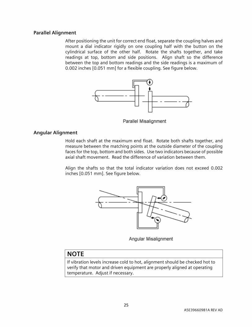
Parallel Alignment
After positioning the unit for correct end float, separate the coupling halves and mount a dial indicator rigidly on one coupling half with the button on the cylindrical surface of the other half. Rotate the shafts together, and take readings at top, bottom and side positions. Align shaft so the difference between the top and bottom readings and the side readings is a maximum of 0.002 inches [0.051 mm] for a flexible coupling. See figure below.
Angular Alignment
Hold each shaft at the maximum end float. Rotate both shafts together, and measure between the matching points at the outside diameter of the coupling faces for the top, bottom and both sides. Use two indicators because of possible axial shaft movement. Read the difference of variation between them. Align the shafts so that the total indicator variation does not exceed 0.002 inches [0.051 mm]. See figure below.
NOTE If vibration levels increase cold to hot, alignment should be checked hot to verify that motor and driven equipment are properly aligned at operating temperature. Adjust if necessary.

26 A5E39660981A REV AD
Foot Plane
The proper foot plane exists when adequate shims have been installed to assure equal pressure on each foot or corner of motor when the mounting bolts are loose. To determine proper foot plane:
1. Mount dial indicator on shaft to be checked so that contact will rest on either the adjacent shaft or a bracket from the foundation or base.
2. With mounting bolts tight and indicator set at zero, release one bolt at the shaft extension end of the unit and check the indicator for a maximum change of 0.001 inch [0.0254 mm].
3. If no change is indicated, retighten the bolt and repeat the process for each of the remaining three mounting bolts.
4. If a change is indicated, add shims under motor foot and retighten until indicator movement is reduced or eliminated.
NOTE 1. The foot plane is of concern for each unit of rotating equipment. Check the
driven equipment if necessary.
2. Base or foundation rigidity can also affect vibration; check for resonance in the supporting structure.
Recheck alignment after any change in shims and document alignment readings for warranty information.
V-Belts
Review the belt manufacturer’s recommendations for maximum speed of sheaves and belts, minimum pitch diameters, maximum allowable number of belts and maximum sheave width. When a motor is ordered for a V-belt drive, check the motor outline for the manufacturer’s limits on belt pull, sheave distance from the motor, and sheave diameter. Use only matched-belt sets. V-grooves must be in line; sheaves must be parallel and axially aligned. Belts must enter and leave sheaves with no side bending. For long bearing life, the belt tension is important; consult belt manufacturer for proper tension to suit drive. Protect belts from grease and oil. NEVER use belt dressing.
27 A5E39660981A REV AD
5.9 Hot Alignment During normal motor operation, the motor frame and rotor will increase in temperature. This increase in temperature results in expansion of the motor components. Therefore, the rotor shaft centerline position will shift in both the axial and vertical directions between "cold" and "hot" conditions. For a 15°C [~27°F] increase in a cast iron motor frame, the vertical growth is approximately SH*1.620E-04 inches [SH*4.115E-03 mm], where SH is the shaft height in inches [or mm]. For a 15°C [~27°F] increase a steel shaft length, the axial growth is SL*1.755E-04 inches [4.458E-03], where SL is the shaft length in inches [or mm]. Axial growth is dependent on the locked bearing arrangement in anti-friction bearings and the core and centerline in sleeve bearing motors. Consult factory for specific axial growth.
WARNING
Rotating parts.
May cause serious injury or death.
Disconnect and lock out power before working on equipment. If the motor application is abnormal (i.e. high temperature, extreme vibration, etc.) consult the factory for special instructions or additional information.
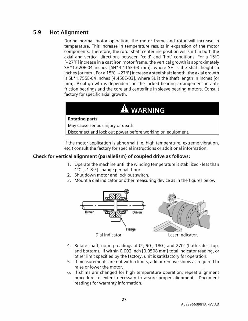
Check for vertical alignment (parallelism) of coupled drive as follows:
1. Operate the machine until the winding temperature is stabilized - less than 1°C [~1.8°F] change per half hour.
2. Shut down motor and lock out switch. 3. Mount a dial indicator or other measuring device as in the figures below.
Dial Indicator. Laser Indicator.
4. Rotate shaft, noting readings at 0°, 90°, 180°, and 270° (both sides, top,
and bottom). If within 0.002 inch [0.0508 mm] total indicator reading, or other limit specified by the factory, unit is satisfactory for operation.
5. If measurements are not within limits, add or remove shims as required to raise or lower the motor.
6. If shims are changed for high temperature operation, repeat alignment procedure to extent necessary to assure proper alignment. Document readings for warranty information.

28 A5E39660981A REV AD
WARNING
Incorrect alignment.
If the machine has not been properly aligned, this will mean the fastening parts are subjected to stress/distortion. Screws may become loose or break, the machine will move, machine parts could be flung out of place. This can result in death, serious injury or material damage.
Carefully align the machine to the driven machine.
5.10 Vibration The standard unfiltered housing vibration limits measured at no load, uncoupled, and with rigid mounting are shown in the table below and are based on the requirements of NEMA MG1-7.8.
Shaft Speed (RPM) Velocity (inches/sec, 0-peak)
1200 – 3600 0.120
1000 0.105
900 0.096
750 0.079
720 0.075
600 0.063
After alignment is complete and foot mounting bolts are tight, run the motor with no load (or minimum possible). Check for vibration. If excessive vibration exists and the alignment is acceptable, check foot plane by loosening one drive end-mounting bolt at a time as detailed previously. This is to be documented for warranty information. When resiliently mounted, allowed levels are 25% higher.
Base or foundation rigidity can also affect vibration, ensure that no resonances exist in the supporting structure. If the shims are changed, alignment must be re-checked and documented for warranty information.
Completing Mechanical Installation
After controlling rotor end float and establishing accurate alignment, it is recommended to drill and ream the foundation plate and motor feet together for dowel pins (refer to Installation - Doweling).
Recheck the parallel and angular alignment before bolting the coupling together. The motor shaft should be level within 0.030 inches [0.762 mm] after alignment.
5.11 Doweling Doweling the motor (and driven unit) accomplishes the following:
1. Restricts movement. 2. Eases realignment if motor is removed from base. 3. Temporarily restrains the motor, should mounting bolts loosen.

29 A5E39660981A REV AD
Inserting Dowel Pins
The following procedure is recommended: 1. Check the alignment after the unit has been in operation approximately
one week. Correct as necessary. 2. Using pre-drilled dowel holes in motor feet as guides, drill into the
mounting base. 3. Ream holes in the feet and base to the proper diameter for tapered dowel
pins. Clean out the chips. 4. Insert dowel pins (two dowel pins diagonally opposed are typical).
5.12 Force Feed Lubrication If force feed lubrication is applied:
1. Flush the lubrication lines thoroughly to ensure the lines are clean before connecting to the bearing housings.
2. Ensure the bearing cavities are filled with the proper oil level before starting. Refer to the motor outline drawing to determine the proper oil level.
3. Be sure that proper oil pressure and flow are provided by the supply system.
4. Verify that the oil drain flow agrees with the factory requirements. The orientation and size of oil drain piping supplied with the motor must not be altered. Oil drain piping should be of the same size or larger from the motor piping to the oil sump and must slope downward. Pressure build up in the drain line between the oil sump and the motor bearing housing can lead to oil leakage. Therefore, the oil drain sump should be vented to atmosphere. If the drain is submerged in the oil sump, back pressure may result.
5. Document readings for warranty information.
5.13 Oil Mist Purge For 500 and 580 frames, when connecting the oil mist purge system, note that the drive end and non-drive end bearing cavities operate at different pressures. To avoid high or low oil levels, extra care should be taken when connecting the system to maintain the proper cavity pressures.

30 A5E39660981A REV AD
5.14 External Wiring
DANGER
Hazardous voltage.
Will cause death, serious injury, electrocution or property damage.
Disconnect all power before working on this equipment.
NOTE Before running motor, see Operation - Initial Start.
Starting and overload control devices must be matched to the motor rating. For safety or convenience, the devices may need to be installed some distance away from the motor. Follow the control manufacturer’s instructions to make the proper installation and connections. Perform the following:
1. Connect the electrical power supply to conform with the National Electric Code (NEC) and any other federal and local regulations. Line voltage and wire capacity must match the motor rating stamped on the nameplate.
2. With the driven equipment disconnected, momentarily energize the motor to check rotation.
3. If the motor is a three-phase machine, reverse the rotation (if applicable) by interchanging any two of the three feeder-side supply cables (phase A, B or C).
NOTE The protection against lightning strikes has to be done at the plant level, the surge arrester at the motor acts as a protection against switching over-voltages only (if equipped). The energy that is dissipated into the surge arrester caused by transient over-voltages through multiple circuit-breaker restrikes is determined by the capacitive energy in the cable and motor stray capacitances against ground and is quite low. The maximum considered surge current through the arrester is 1 kA, the surge energy rating class E (9kJ/kVMCOV) is considered as being sufficient.
Grounding
The motor frame and main terminal box (if supplied) have a landing point for an equipment ground conductor. The ground conductor brought to these locations should be sized in accordance with NEC and any other federal and local regulations.

31 A5E39660981A REV AD
Electrical Connections
When tightening bolts that secure electrical connections, the tightening torque of the fasteners is very important. Unless local regulations differ, use tightening torque values based on UL 486A - 486B tables 21, 22, 23 and 24 when making electrical connections to the motor.
Cable Designations
The following table explains the function of various stator cable designations.
Termination Label Function
T1, T2, T3 Stator cables for primary winding.
T4, T5, T6 Opposite end of primary winding phases from T1, T2, T3 respectively.
T7, T8, T9 Stator cables used to reconnect for different operating voltages.
T11, T21, T31 Stator cables for 2nd winding of stator with two parallel windings.
T41, T51, T61 Opposite end of 2nd winding phases from T11, T21, T31 respectively.
NOTE
Multiple cables in parallel with identical labels may be provided for current-carrying capacity.
Insulating Connections in the Main Terminal Box
The following procedure is the recommended insulation practice for the electrical connections made between the motor’s power cables and the external supply cables (with or without standoff insulators/bus bar assemblies):
1. Apply the number of half-lapped layers of silicone rubber tape specified in the following table, Insulating Connections. Typically, the center of the rubber tape is marked with a line for reference of half-lap.
2. The last silicone rubber tape layer must overlap the exiting insulation on the bus or cable as specified on the Insulating Connections table.
3. When taping multiple cable connections, be sure to wrap the crotch with the required number of layers.
Insulating Connections
Rated Voltage (Volts)
Minimum Overlap (inches / mm)
Number of Layers of Silicone Rubber Tape
0 – 600 1.50 / 38.1 2 601 – 2400 1.50 / 38.1 2
2401 – 4200 2.00 / 50.8 3 4201 – 5500 2.25 / 57.2 4 5501 – 7200 2.50 / 63.5 5
32 A5E39660981A REV AD
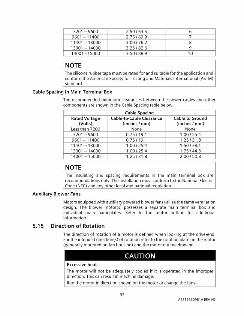
7201 – 9600 2.50 / 63.5 6 9601 – 11400 2.75 / 69.9 7
11401 – 13000 3.00 / 76.2 8 13001 – 14000 3.25 / 82.6 9 14001 - 15000 3.50 / 88.9 10
NOTE The silicone rubber tape must be rated for and suitable for the application and conform the American Society for Testing and Materials International (ASTM) standard.
Cable Spacing in Main Terminal Box
The recommended minimum clearances between the power cables and other components are shown in the Cable Spacing table below.
Cable Spacing Rated Voltage
(Volts) Cable-to-Cable Clearance
(inches / mm) Cable to Ground
(inches / mm) Less than 7200 None None 7201 – 9600 0.75 / 19.1 1.00 / 25.4
9601 – 11400 0.75 / 19.1 1.25 / 31.8 11401 – 13000 1.00 / 25.4 1.50 / 38.1 13001 – 14000 1.00 / 25.4 1.75 / 44.5 14001 – 15000 1.25 / 31.8 2.00 / 50.8
NOTE The insulating and spacing requirements in the main terminal box are recommendations only. The installation must conform to the National Electric Code (NEC) and any other local and national regulation.
Auxiliary Blower Fans
Motors equipped with auxiliary powered blower fans utilize the same ventilation design. The blower motor(s) possesses a separate main terminal box and individual main nameplates. Refer to the motor outline for additional information.
5.15 Direction of Rotation The direction of rotation of a motor is defined when looking at the drive-end. For the intended direction(s) of rotation refer to the rotation plate on the motor (generally mounted on fan housing) and the motor outline drawing.
CAUTION
Excessive heat.
The motor will not be adequately cooled if it is operated in the improper direction. This can result in machine damage.
Run the motor in direction shown on the motor or change the fans.

33 A5E39660981A REV AD
CAUTION Aluminum Fans.
Aluminum press fit fans should not be re-used if removed for any reason such as directional changes.
NOTE It may be necessary to rebalance the rotor if the fans are changed.
The external fan direction must be considered if the motor is equipped with a shaft mounted external fan. Refer to the following External Cooling Fan table to identify which motors have single or bi-directional fans.
External Cooling Fan Motor Frame
Size
Motor Speed 3600 – 3000 RPM
(2 pole) 1800 – 1500 RPM
(4 pole) 1200 RPM & Slower
(6 or more poles) 400 Bi-directional
Bi-directional
S449
Single Direction Only
500
580 SH400 SH560 SH450
Single Direction Only Bi-directional 880
5.16 Intrinsically Safe Intrinsically safe circuits for sensors or probes must be in accordance with NEC NFPA-70 or IEC/EN 60079-14 when selecting and routing connecting cables.
CAUTION
Connecting the temperature sensors.
Temperature sensors may be connected only to intrinsically safe circuits with certified evaluation devices. The maximum permissible input currents and powers must not be exceeded, other may result in damage.
If shielded, intrinsically safe temperature sensors are fitted or mounted, they must be connected using the blue connecting terminals. The cable shield should be grounded just once at the source; multiple grounding is not permitted.

34 A5E39660981A REV AD
5.17
Typical Motor Control Settings
Suggested Vibration Limits
Shaft Speed (RPM) 3600 1800 1200 900 and Slower
Shaft Vibration (mils, pk-to-pk) 3.3 3.7 4.3 5.0
Housing Vibration (in./sec., 0-pk) 0.25 0.25 0.25 0.25
(1) Recommended delay after trip condition is reached before activating the control device. (2) Increase as necessary to avoid nuisance trips. (3) This is the maximum deviation from the average of the three phases.
Alarm
Trip (Shutdown)
Timer Trip Setting (1)
Winding Temperature
Class B Insulation 130°C 155°C
Class F Insulation 155°C 170°C
Motor Bearing Temperature (Thermocouple or RTD’s)
Sleeve Bearing 100°C 105°C
Antifriction Bearing 100°C 105°C
Ground Fault
4 Amps (2)
Primary Circuit
8 Amps (2) Primary Circuit
0.2 sec. (2)
Instantaneous Overcurrent
With ½ Cycle Delay 1.8 times Locked Rotor Amps
(2)
Without Time Delay 2.4 times Locked Rotor Amps
(2)
Maximum Voltage
>110 % of Rated Voltage 10 sec.
Minimum Voltage (the minimum voltage also applies to starting unless otherwise specified)
<90 % of Rated Voltage 10 sec.
Maximum Frequency Deviation
± 5% 10 sec.
Maximum of Voltage Plus Frequency Deviation
± 10% 10 sec.
Maximum Voltage Unbalance (3)
1% 15 sec.
Maximum Current Unbalance (3)
8% 15 sec.

35 A5E39660981A REV AD
(4) The information shown above are manufacturer suggestions and may vary based on different applications.

36 A5E39660981A REV AD
6 Operation 6 6.1 Initial Start and Commissioning
CAUTION
Do not exceed the number of specified hot and cold starts per hour.
Excessive starting will cause overheating.
Allow the proper cooling period between starts to permit the stator windings and rotor to cool.
NOTE
If the motor has been out of service or in storage for more than 30 days, refer to Storage – Preparation for Service.
NOTE Avoid shutting down the machine during startup, as this may cause over-voltages. This type of damage can occur regardless of the motor size or the type of switch used.
NOTE If vacuum circuit breakers and vacuum contactors are applied, use the appropriate surge suppressors, such as the Siemens 3EF (zinc-oxide varistor with spark gap).
NOTE
If equipment is operated intermittently in very damp locations, it should be protected by space heaters. To retard corrosion, grease all machined fits when the unit is reassembled after a maintenance check.
Motor Pre-Start and Commissioning Checklist
The following lists provide a general guideline of the recommended steps after a successful installation and before the first motor start. Verifications, tests, and the overall sequence of steps required can vary based on the application, types of accessories used, and the specific motor design in question. To ensure the motor is commissioned properly, please contact the Siemens Service Center (1-800-333-7421 or for outside the US 1-423-262-5710) to schedule a Siemens Certified Technician for on-site commissioning of the motor.

37 A5E39660981A REV AD
Pre-Start Checklist
1. Verify the motor nameplate matches the documentation, such as the motor outline drawing and data sheets provided by Siemens.
2. Physically inspect the motor for any damage, debris, and loose hardware. 3. Ensure the motor hold-down bolts, lead cables, and feeder cable
connections are properly secured and torqued. 4. Visually inspect that all grounding cables are connected to the ground lugs.
For VFD operation, ground cables should be finely stranded or braided. 5. Check the supplied accessory wiring such as the stator/rotor RTD’s,
vibration probes, etc. to ensure the wires are properly terminated. 6. Rotate the motor shaft by hand; for sleeve bearings a spanner wrench may
be necessary. This step may have been performed during installation and may not be necessary.
7. Verify that the motor’s internal space heaters (if equipped) have been energized while in storage.
8. Prior to energizing the motor, perform an insulation resistance and polarization index test on the stator windings. Refer to Maintenance - Insulation Resistance, for information on the test and acceptance criteria.
9. If insulated bearings are used, check the bearing(s) insulation resistance using an Ohmmeter. Remove any ground straps attached to the bearing and measure the resistance from the frame to the shaft. Measured resistance values in excess of 3000 Ohms with a 30-50V test voltage are typical.
10. Verify the shaft magnetic center prior to coupling the load. Slight axial movement is normal. If the magnetic center indicators are not visible check the lubrication plate on the motor for the magnetic center in inches. Use an insulated scribing tool or check the shaft voltage prior to making any marking or scribe on the shaft.
11. Ensure the motor’s inlet/exhaust openings are clear of debris and have adequate space for cooling and to prevent recirculation.
12. For pipe ventilated machines, which utilize inlet and/or outlet ducting to deliver fresh air, ensure the ducting or piping is symmetrical.
13. If the motor is equipped with air filters; verify filters are correctly placed, clean, and contain the OEM filter media.
14. For forced lubricated sleeve bearings, the flow rate and oil level in the bearings should be confirmed with the lube plate and the motor outline drawing prior to commissioning. The inlet and outlet oil piping locations should also be checked with the motor outline drawing because this can sensitive to the direction of rotation.
15. Sleeve bearings are not shipped with oil in the reservoir, please add the appropriate oil type, grade and quantity as shown on the motor outline drawing. The oil level in inches is located on the lubrication plate.
16. For grease lubricated bearings, verify the bearings are properly greased before running motor. Grease lubricated bearings are lubricated prior to shipment by Siemens. Refer to motor nameplate for grease type and quantity. Do not mix grease types.
17. For forced oil lubrication (flood lube), ensure the outlet piping is sloped downwards at least 3 degrees or a 5% grade. Outlet piping must be vented

38 A5E39660981A REV AD
to atmospheric pressure; no traps are permitted. Ensure outlet piping does not reduce in size.
18. For motors which utilize auxiliary powered blower motors for cooling, ensure the power cables are connected and are properly torqued to the blower motor terminals.
19. For motors equipped with shaft proximity probes, check the output voltage with the proximity probe manufacture suggestion guidelines.
20. Ensure all piping to the motor is adequately supported. 21. Verify that the alignment from motor to the driven equipment is correct.
Refer to Installation - Alignment for further details. For additional support, contact the Siemens Customer Service for a Certified Technician.
22. Confirm that the motor, starting equipment and the control device connections match the supplied wiring diagrams on the motor outline drawing.
23. Ensure the motor’s power cables are phased correctly for the desired shaft rotation. Refer to the motor’s main nameplate for the proper phase and motor terminal designations.
24. Verify the application site can provide the supply voltage, frequency and current capacity for the motor rating (see main nameplate and datasheet).
First Start Checklist
1. Ensure the safety alarm and trip settings are properly configured. Refer to Installation - Typical Motor Control Settings for recommended settings.
2. The motor’s starting limitations are defined as the Starting Duty. Refer to the Starting Duty nameplate (if equipped) or the motor data sheet for the recommended number of starts and cooling period. Please note, a speed vs torque load demand curve along with the load inertia are required for this information.
3. A flood lube oil system should be turned on and ran for at least 30 minutes prior to motor operation to inspect for oil leaks, proper pressure, flow, and draining capability.
4. Bump-start the motor to confirm the direction of rotation. Additionally, if equipped, check the rotation of the auxiliary blower motors (as shown on the motor outline drawing).
5. If possible, run the motor uncoupled for 2-4 hours or until the temperature stabilizes (less than 1oC increase in 30 minutes).
a. Note – a technician is recommended to monitor the motor during the initial startup. Monitor and document any leaks, temperature or vibration spikes, or unusual/excessive noises. If present, stop the motor immediately and investigate the cause before operation.
6. Run motor under load for approximately 4 hours or until the temperature stabilizes (less than 1oC increase in 30 minutes).
a. Note – a technician is recommended to monitor the motor during the initial startup. Monitor and document any leaks, temperature or vibration spikes, or unusual/excessive noises. If present, stop the motor immediately and investigate the cause before operation.
7. After shutdown, verify the hot alignment is within specifications mentioned in Installation – Hot Alignment.
39 A5E39660981A REV AD
Circulating-Oil Lubrication Systems
1. Observe the notes and instructions by the journal bearing manufacturer and the circulating-oil system supplier.
2. When selecting components for the oil lines, check the resistance of the materials used.
3. Arrange and route the oil piping to prevent excessive stress, strain or vibration loads.
4. Ensure the oil outlet piping is properly vented to atmospheric pressure. 5. Ensure the oil outlet piping does not reduce in size. 6. Fill the oil reservoirs to the normal level (see motor outline drawing) using
only fresh filtered oil with ISO 4406 17/15/12 cleanliness. 7. Note the pressure load on the oil supply lines.
a. Oil supply pressure outboard of motor oil supply orifice should be monitored. Any reducers and/or bends between the point of measurement and the motor oil supply orifice will cause a reduction in supply pressure.
b. Ensure that the gradient of the return line is at least 3° and in a maximum roll condition, at least a 1° gradient is maintained.
c. The supply oil pressure tolerance is -0, +5PSI. 8. The circulating-oil system must be in operation prior to starting the motor.
6.2 Normal Operation Start the motor in accordance with the standard instructions for the starting equipment used. In some cases, the load should be reduced to the minimum, particularly for reduced voltage starting, and/or high inertia connected loads.
DANGER
Explosion Hazard.
If the motor was provided with a ground strap on the insulated drive-end bearing, then this bridging must not be removed. Removal of the strap would allow a potential difference between the rotor and the grounded machine. This may allow sparking, which especially in an explosive atmosphere can ignite the surrounding gas and explode. Electric shock is also a risk. Death, serious injury or machine and equipment damage may result.
1. If equipped, do not disconnect the ground strap for the bearing insulation from the drive-end housing during operation.
2. Comply with all notices on the motor and the outline drawing relating to the bearing insulation and bridging options.

40 A5E39660981A REV AD
WARNING
Fire hazard resulting from hot surfaces.
Certain parts of the machine become hot during operation. Severe burns, as well as serious injury or death can result from contact with these parts.
1. Check the temperature of the parts before touching them. If required, apply suitable protective measures.
2. Allow the machine to cool before starting work on the machine.
CAUTION
Excessive machine temperature.
If the anti-condensation heaters are operated while the machine is running, this will increase the temperatures inside the machine and may result in material damage.
1. Make sure that the anti-condensation heaters are switched off before the machine is switched on.
2. Only operate anti-condensation heating when the machine is switched off.
NOTE Risk of corrosion due to condensation.
Humid air can condense inside the machine during operation as a result of intermittent duty or load fluctuations. Condensation can collect inside the motor. Damage such as rust can result.
1. Apply space heaters during non-operational periods.
2. Ensure winding is dry prior to starting.
6.3 Voltage/Frequency Variation Motors will operate successfully under the following conditions for voltage and frequency variation (NEMA MG-1), but not necessarily in accordance with the standards established for operating under rated conditions:
1. If the voltage variation does not exceed 10% above or below the rated voltage with all phases balanced. Voltage unbalance should not exceed 1%.
2. If the frequency variation does not exceed 5% above or below the rated frequency.
3. If the sum of the voltage and frequency variations does not exceed 10% above or below rated values provided; the frequency variation must not exceed 5%.
41 A5E39660981A REV AD
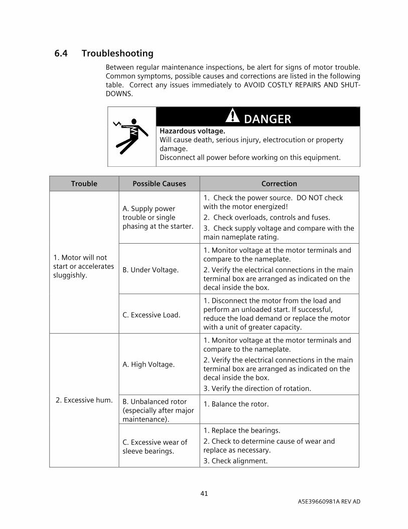
6.4 Troubleshooting Between regular maintenance inspections, be alert for signs of motor trouble. Common symptoms, possible causes and corrections are listed in the following table. Correct any issues immediately to AVOID COSTLY REPAIRS AND SHUT- DOWNS.
Trouble Possible Causes Correction
1. Motor will not start or accelerates sluggishly.
A. Supply power trouble or single phasing at the starter.
1. Check the power source. DO NOT check with the motor energized!
2. Check overloads, controls and fuses.
3. Check supply voltage and compare with the main nameplate rating.
B. Under Voltage.
1. Monitor voltage at the motor terminals and compare to the nameplate.
2. Verify the electrical connections in the main terminal box are arranged as indicated on the decal inside the box.
C. Excessive Load.
1. Disconnect the motor from the load and perform an unloaded start. If successful, reduce the load demand or replace the motor with a unit of greater capacity.
2. Excessive hum.
A. High Voltage.
1. Monitor voltage at the motor terminals and compare to the nameplate.
2. Verify the electrical connections in the main terminal box are arranged as indicated on the decal inside the box.
3. Verify the direction of rotation.
B. Unbalanced rotor (especially after major maintenance).
1. Balance the rotor.
C. Excessive wear of sleeve bearings.
1. Replace the bearings.
2. Check to determine cause of wear and replace as necessary.
3. Check alignment.
DANGER
Hazardous voltage. Will cause death, serious injury, electrocution or property damage. Disconnect all power before working on this equipment.

42 A5E39660981A REV AD
Trouble Possible Causes Correction
3. Regular clicking. A. Foreign matter in the air gap.
1. Remove any foreign matter.
4. Rapid knocking. A. Bad anti-friction bearing or dirt in lubricant.
1. Replace damaged bearing(s).
2. Clean the grease cavities. Some motors will require the bearing capsules to be removed.
3. Use new lubricant.
5. Vibration.
A. Misalignment in the coupling or the feet.
1. Realign the motor and driven equipment.
B. Accumulation of dirt on fan(s).
1. Clean the interior of the motor.
C. Vibration in driven equipment.
1. Run the motor unloaded and check for vibration. If isolated to driven equipment, eliminate the source.
D. System natural frequency (resonance).
1. Alter the rigidity of the base structure.
6. Vibration following motor repair.
A. Rotor out of balance (balance weights of the fans shifted on the rotor).
1. Rebalance the rotor.
7. Motor overheating. (Check with a thermocouple or by the resistance method, do not depend on touch).
A. Overload.
1. Measure the line current under load and compare with nameplate current rating.
2. Reduce the load demand or replace the motor with a unit of greater capacity.
B. Single phasing. 1. Check the balance of current across all phases with the motor under load.
C. Dirt/debris in the motor.
1. Verify air is flowing through inlets and outlets.
2. Check cleanliness of filters, if equipped. If filters are found to be clogged, check interior of machine for dirt and debris if possible.
4. Clean motor air paths if necessary.
D. Unbalanced voltage. 1. Verify the voltage balance across all phases.
E. Rotor rubbing on the stator.
1. Check the symmetry of air gap in 4 locations; if symmetry is poor, internal repairs are necessary.
F. Open stator windings.
1. Disconnect motor from the load.
2. Check the idle amps for balance in all three phases.
3. Check the balance of the stator resistance in all three phases.

43 A5E39660981A REV AD
Trouble Possible Causes Correction
7. Motor overheating cont. (Check with a thermocouple or by the resistance method, do not depend on touch).
G. Airflow problem.
1. Check the air intake and exhaust for obstructions.
2. Check the air inlet temperature against the rated ambient temperature on rating plate.
H. Over voltage/under voltage.
1. Check the supply voltage and compare to rating on the main nameplate.
I. Improper electrical connections.
1. Recheck electrical connections.
J. Excessive ambient temperature
1. Check to see if the intake air temperature exceeds that of the maximum air temperature listed on the main nameplate.
8. Fine dust under the coupling with rubber buffers/pins.
A. Misalignment 1. Realign the motor and drive equipment. 2. Inspect the coupling.
9. Bearing(s) overheating
A. Oil level is too high or low (sleeve bearing)
1. Correct the oil level. Refer to the motor outline drawing to determine proper oil level.
B. Misalignment 1. Realign the motor and driven equipment.
C. Excessive tension in belt drive.
1. Reduce the tension to point of adequacy.
D. Excessive end thrust.
1. Reduce the thrust.
2. Recheck the mounting and alignment.
E. Too much grease (ball or roller bearing)
1. Relieve supply to point set by manufacturer. Some motors will require bearing capsules to be removed and cleaned.
F. Sticking oil ring (sleeve bearing).
1. Clean, repair, or replace. Recheck mounting.
G. Excessive ambient temperature
1. Check to see if the intake air temperature exceeds that of the maximum air temperature listed on the main nameplate.
10. Oil leakage or excessive oil usage.
A. Parts not sealed properly.
1. Seal the pipe plugs and connections. 2. Seal the bearing housing split line. 3. Seal the oil seal joint.
B. Clogged oil return holes in oil seals.
1. Dismantle and clean the oil seals.
11. Excessive oil level fluctuation.
A. High pressure or vacuum in bearing cavity.
1. Measure pressure or vacuum using manometer (Refer to Maintenance – Bearings, Cavity Pressures). 2. Check atmospheric vents for obstructions. 3. Check the oil seal gap for uniformity.

44 A5E39660981A REV AD
7 Maintenance 7 7.1 Preventative Maintenance
Motors are designed to provide many years of reliable service with minimum attention. Trouble-free operation cannot be expected if proper maintenance is postponed or neglected. Provide proper maintenance on the equipment by following the instructions contained herein. Be certain personnel review, understand, and follow these procedures during periodic maintenance inspections.
DANGER
Hazardous voltage.
Will cause death, serious injury, electrocution or property damage.
Disconnect all power before working on this equipment.
Maintenance should be performed only by qualified personnel.
CAUTION
Foreign objects in and on the machine.
Foreign objects such as dirt, tools or loose components, such as screws etc., can be left by accident inside the machine after maintenance is performed. These can cause short circuits, reduce the performance of the cooling system or increase noise in operation. They can also damage the machine.
1. When carrying out maintenance work, make sure that no foreign bodies are left in or on the machine.
2. Securely attach all loose parts again once you have completed the maintenance procedures.
3. Carefully remove any dirt or debris.
NOTE
If equipment is operated intermittently in very damp locations, it should be protected by space heaters. To retard corrosion, grease all machined fits when the unit is reassembled after a maintenance check.

45 A5E39660981A REV AD
Routine Maintenance Plan
The table below represents a typical suggested maintenance plan, actual required maintenance will vary based on the application and environmental conditions. For additional support and recommendations, please contact Siemens Customer Service at 1-800-333-7421 or for outside the US, 1-423-262-5710. For maintenance that requires the motor to be uncoupled from the load, verify magnetic center to ensure the proper end play.
Siemens Suggested Maintenance Plan
Act
ion
s E
very
6
Mo
nth
s
1. Visual inspection, clean and replace (if necessary) the air inlet filters (WPII).
2. For pipe ventilated motors, visually inspect the ducting leading to the motor (e.g. obstructions or blockages)
3. Check accessory functionality. Replace any defective components.
(RTD’s, space heaters, proximity probes, pressure sensors, thermostats, etc.)
4. For oil lubricated bearings, visually inspect and replace (if necessary) with fresh oil.
Act
ion
s E
very
Ye
ar
1. Visual inspection for cleanliness, damage and wear to both the internal and external motors surfaces. Check for excessive loading (thermal).
2. Inspect the motor for any leaks (oil and water).
3. Visual inspection of the stator insulation. Inspect the winding overhang for dirt, debris, foreign objects, or sign of damage (i.e. tracking, thermal damage, rips/tears). Observe if the end winding bracing appears to have shifted and check that the slot wedges are firmly seated and not loose.
4. Ensure the proper tightening torques on the ground lugs and that the ground cable connection surface is free from dirt, debris or any other environmental contamination.
5. Visually inspect the terminal boxes. Inspect for internal dirt/debris, signs of condensation, thermal damage and electrical tracking. Ensure the clearances between the cables is still adequate for the voltage class. Inspect the cables for wear or damage. Check the mounting bolts for the terminal box cover and the box interface are properly torqued. Ensure the gasket material is clean and not degraded. Verify the blow out panel is still intact.
6. Check the torque values on all Siemens provided foundation bolts.
7. Confirm the shaft alignment is correct.
8. Perform an insulation resistance / polarization index on the stator winding for continuous duty applications (for intermittent duty, check every two months).
Act
ion
s E
very
5 Y
ea
rs
1. Visually inspect the rotor. Inspect the axial flow vents for blockages and debris. Inspect the shaft bearing journals and seal fits. Inspect the external balance weights by hand to ensure they are tightly secured.
2. Visually inspection of the oil and air seals (both inboard and outboard). Inspect the bearings for damage or excessive wear.
3. Check the bearing insulation resistance.
4. Ensure the internal airflow paths are clear from obstructions and blockages.

46 A5E39660981A REV AD
A definite schedule of preventive maintenance inspections should be established to avoid breakdown, serious damage and extensive downtime. The schedule will depend on operating conditions and experience with similar equipment. To assure adequate maintenance, and warranty consideration, it is essential that complete records be kept for each motor, including description and rating, maintenance schedule and repairs required or carried out. The maintenance plan does not represent an exhaustive survey of maintenance steps necessary to ensure safe operation of this equipment. Particular applications may require further procedures. Should further information be desired, or should particular problems arise which are not covered sufficiently for the purchaser’s purposes, contact the factory for additional support.
WARNING
Improper maintenance can cause death, serious injury or property damage.
Use only factory authorized parts for repair of equipment.
Maintenance should be performed only by qualified personnel.
NOTE If air inlet filters are installed, the differential pressure drop across them can be used as a proxy for the condition of the filters themselves. A larger pressure gradient indicates a larger degree of buildup (debris or contaminants) in the filters. If the motor is equipped with a differential pressure switch, the switch is set at the factory to trip when a pressure is reached that indicates a 50% blockage of filter area, which is the maximum recommended filter blockage. If the motors are equipped with a differential pressure gauge or transmitter, the recommended set point for control equipment will be provided with the motor drawings. Note, a differential pressure switch normally has only two conditions (make and break), thus it cannot be used to set both an alarm and a trip point for a monitoring system
7.2 Inspection Each motor should be inspected at regular intervals. The frequency and thoroughness will depend on the operating hours, nature of service, and the environment.
Cleanliness
The exterior of the machine should be kept free of oil, dust, dirt, water, chemicals and any other environmental contaminants. It is particularly important to keep the fan housing air intake and exhaust openings free of obstructions.
CAUTION Flying dirt, dust or other particles.
May cause eye injury.
Wear safety glasses and dust mask when using compressed air.

47 A5E39660981A REV AD
NOTE
Cleaning with compressed air.
If cleaning is performed using compressed air, chips of metal can be blown into the winding head. This can damage the insulation and result in clearances and creepage distances less than the minimum allowable. This may cause damage to the machine extending to total failure.
When cleaning with compressed air, ensure there is adequate extraction.
Anti-friction Bearings
Access to the motor interior can be gained by removing the bearing housing as follows: 1. For access to the non-drive end bearing housing, remove the external fan housing
and external fan (shaft mounted or blower). 2. Support the rotor shaft extension with a jack or a supporting fixture. 3. Remove the bolts holding the inner bearing end cap to the housing. 4. Remove the bolts holding the bearing housing to the yoke. 5. Remove the bearing housing by pulling it away from the face of the yoke.
Sleeve Bearings – 500 Frame
Access to the motor interior can be gained by removing the upper half of the horizontally split bearing bracket. The entire procedure can be done without disturbing the bearing enclosure or coupling alignment of the motor to the load. The split-bearing capsule can be disassembled by:
1. For access to the non-drive end bearing housing, remove the external fan housing and external fan (shaft mounted or blower).
2. Remove the parting bolts at the horizontal split. 3. Remove the bolts at the outer circumference of the upper half of the split-bearing
bracket. 4. Pull the upper bracket away from the frame and remove.
Sleeve Bearing – 580, 880, SH400, SH450 & SH560 Frames
Access to the motor interior can be gained by removing the bearing bracket as follows: 1. For access to the non-drive end bearing housing, remove the external fan
housing and external fan (shaft mounted or blower). 2. First remove the bearing housing cap and bearing liners. Refer to Maintenance
– Bearing Replacement – Sleeve Bearing Replacement 3. Remove the floating labyrinth seals or oil seals as equipped. 4. Remove the bearing housing from the bearing bracket. 5. Carefully remove the bearing bracket with inner seal from the motor.
Stator Insulation
After the bearing housings and air deflectors are removed, the stator coils can be visually inspected. If any damage is visibly present on the stator windings/insulation system during a routine inspection or cleaning, please contact the Siemens factory for guidance.

48 A5E39660981A REV AD
Loading
Overloading causes overheating and reduces the stator’s insulation life. A winding subjected to a 10°C temperature rise above the maximum limit for its class may have its insulation life halved. Underloading a motor can be improper as it may operate at a lower power factor and efficiency which results in higher power cost.
Temperature
Motors operating under normal conditions become quite warm. Although some places may feel hot to the touch, the unit may be within the limits. When measuring the total temperature by winding resistance or the stator’s embedded detector (RTD), the total temperature should not exceed the limits in the following tables. The temperature values in the tables are in accordance with NEMA MG-1. When operating the motor at full load (rated horsepower):
When operating the motor at a 1.15 service factor load (if applicable):
Class of Insulation System
B F H
Temperature by Resistance
All HP 130°C
(266°F) 155°C
(311°F) 175°C
(347°F)
Temperature by Embedded Detector
1500HP or less 140°C
(284°F) 165°C
(329°F) 190°C
(373°F)
Over 1500HP-Under 7000V
135°C (275°F)
160°C (320°F)
185°C (365°F)
Over 1500HP-Over 7000 V
130°C (266°F)
155°C (311°F)
175°C (347°F)
These temperatures represent the maximum temperature for each class of insulation and include a 40°C [104°F] ambient temperature. Operation above these temperatures will result in reduced insulation life.
Class of Insulation System
B F H
Temperature by Resistance
All HP 120°C
(248°F) 145°C
(293°F) 165°C
(329°F)
Temperature by Embedded Detector
1500HP or less 130°C
(266°F) 155°C
(311°F) 180°C
(356°F)
Over 1500HP-Under 7000V
125°C (257°F)
150°C (302°F)
175°C (347°F)
Over 1500HP-Over 7000 V
120°C (248°F)
145°C (293°F)
165°C (329°F)

49 A5E39660981A REV AD
Vibration
Most problems can be detected when visually inspected. Check for: 1. Loose or missing parts, such as fan blades, nuts, bolts, couplings, etc. 2. Accumulation of dirt or debris on the fan or rotor. 3. Associated driven equipment (or drive train) - Disconnect all equipment to
determine where the vibration is being generated. 4. Foundation construction - Base, grouting and associated equipment supporting
drives must be in good condition. Vibration can be amplified by weak construction. Vibration of a base just below the motor feet should not exceed 25% of the motor vibration.
5. History - When was vibration first noted? Was there a change in the loading and/or the duty of the equipment? Has ambient vibration changed?
More important than the actual vibration is the vibration change over a period of time.
7.3 Corrective Maintenance The two main factors that require corrective maintenance are electrical failure or mechanical failure. The first sign of electrical failure is usually a low stator insulation resistance. Mechanical failures are usually preceded by excessive bearing noise, vibration or heat.
Low Insulation Resistance
Factors that usually cause low stator insulation resistance measurements are: 1. Dirty windings (oil, dust, grease, salt, etc.). 2. Excessive moisture. 3. Mechanically damaged insulation. 4. Heat deterioration
Dirty windings can be cleaned, and moist windings dried; however, items 3 and 4 require extensive repairs by a certified service center.
Cleaning
Clean the outside of the motor regularly. Actual conditions existing around the motor dictate the frequency of cleaning operations. Use the following procedures as they apply.
1. Wipe off any dust, dirt, oil, water, etc., from external surfaces of the motor. 2. Remove dirt, dust, or other debris from the ventilating air inlets and exhausts.
Do not operate motor with air passages blocked or restricted.
CAUTION Flying dirt, dust or other particles.
May cause eye injury.
Wear safety glasses and dust mask when using compressed air.
7.4 Cleaning - Rotor Carefully remove the rotor from the stator bore ensuring not to damage the stator insulation. Inspect and clean as necessary.

50 A5E39660981A REV AD
7.5 Cleaning - Stator Siemens’ form wound VPI (vacuum pressure impregnated) insulated coils may be cleaned with a quick drying solvent compatible with the insulations system and lint free cloths or steam cleaned with low-pressure steam. As an alternative, water and a non-caustic industrial degreaser/detergent may be used. After cleaning, the entire stator shall be oven baked at approximately 95°C [203°F] for 12 hours and then at 110°C [230°F] for 12 hours.
The stator winding insulation resistance should be measured before and after any cleaning operation.
7.6 Cleaning – Bearing and Housing Ensure the area is clean before disassembly to prevent unwanted contamination during the cleaning process and re-assembly. Use the following instructions to clean the bearing housing: 1. When disassembling the bearing housing, make note of how many and where the
bearing shims are installed so they are re-installed appropriately. 2. With the bearing exposed, use a petroleum solvent and lint free rags to thoroughly
wipe out the existing oil or grease, contamination, and any bearing sealants. Anti-friction bearings should be cleaned without being removed from the shaft.
3. Clean all bearing seals, rings and other bearing hardware with the solvent. 4. Inspect all components (bearings and hardware) and the bearing journal for any
damage. Replace or repair as necessary. 5. Pack the bearing with grease or lightly oil and make sure shims are in place. 6. Rotate the rotor by hand to ensure it rotates freely before completing assembly. 7. Re-assemble the bearing using the appropriate bearing sealant (if necessary) and fill
the grease cavity or oil reservoir to the quantity shown on the lube plate or the motor outline drawing.
7.7 Testing – Insulation Resistance and Polarization Index
DANGER Hazardous voltage.
Will cause death, serious injury, electrocution or property damage.
Disconnect all power before working on this equipment.
CAUTION High Voltage.
May damage semi-conductors, current transformers, voltage regulators, and other devices.
Disconnect from the circuit before testing the insulation resistance.
CAUTION
Grounding.
Ensure the motor frame, stator mounted space heaters, and all the temperature sensors are grounded prior to testing.
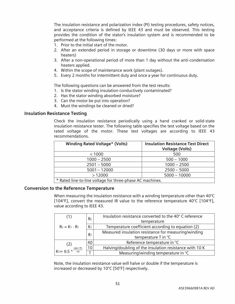
51 A5E39660981A REV AD
The insulation resistance and polarization index (PI) testing procedures, safety notices, and acceptance criteria is defined by IEEE 43 and must be observed. This testing provides the condition of the stator’s insulation system and is recommended to be performed at the following times: 1. Prior to the initial start of the motor. 2. After an extended period in storage or downtime (30 days or more with space
heaters) 3. After a non-operational period of more than 1 day without the anti-condensation
heaters applied. 4. Within the scope of maintenance work (plant outages). 5. Every 2 months for intermittent duty and once a year for continuous duty.
The following questions can be answered from the test results: 1. Is the stator winding insulation conductively contaminated? 2. Has the stator winding absorbed moisture? 3. Can the motor be put into operation? 4. Must the windings be cleaned or dried?
Insulation Resistance Testing
Check the insulation resistance periodically using a hand cranked or solid-state insulation resistance tester. The following table specifies the test voltage based on the rated voltage of the motor. These test voltages are according to IEEE 43 recommendations.
Winding Rated Voltage* (Volts) Insulation Resistance Test Direct Voltage (Volts)
< 1000 500 1000 – 2500 500 – 1000 2501 – 5000 1000 – 2500
5001 – 12000 2500 – 5000 > 12000 5000 – 10000
* Rated line-to-line voltage for three-phase AC machines.
Conversion to the Reference Temperature
When measuring the insulation resistance with a winding temperature other than 40°C [104°F], convert the measured IR value to the reference temperature 40°C [104°F], value according to IEEE 43.
(1)
RC = KT · RT
RC Insulation resistance converted to the 40° C reference
temperature
KT Temperature coefficient according to equation (2)
RT Measured insulation resistance for measuring/winding
temperature T in °C
(2)
KT= 0.5 ^ (40−T)
10
40 Reference temperature in °C 10 Halving/doubling of the insulation resistance with 10 K T Measuring/winding temperature in °C
Note, the insulation resistance value will halve or double if the temperature is increased or decreased by 10°C [50°F] respectively.
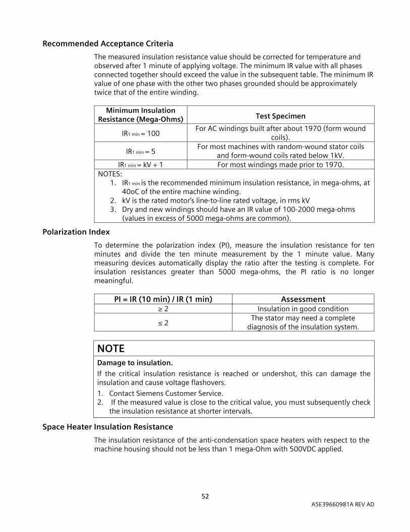
52 A5E39660981A REV AD
Recommended Acceptance Criteria
The measured insulation resistance value should be corrected for temperature and observed after 1 minute of applying voltage. The minimum IR value with all phases connected together should exceed the value in the subsequent table. The minimum IR value of one phase with the other two phases grounded should be approximately twice that of the entire winding.
Minimum Insulation Resistance (Mega-Ohms)
Test Specimen
IR1 min = 100 For AC windings built after about 1970 (form wound
coils).
IR1 min = 5 For most machines with random-wound stator coils
and form-wound coils rated below 1kV. IR1 min = kV + 1 For most windings made prior to 1970.
NOTES: 1. IR1 min is the recommended minimum insulation resistance, in mega-ohms, at
40oC of the entire machine winding. 2. kV is the rated motor’s line-to-line rated voltage, in rms kV 3. Dry and new windings should have an IR value of 100-2000 mega-ohms
(values in excess of 5000 mega-ohms are common).
Polarization Index
To determine the polarization index (PI), measure the insulation resistance for ten minutes and divide the ten minute measurement by the 1 minute value. Many measuring devices automatically display the ratio after the testing is complete. For insulation resistances greater than 5000 mega-ohms, the PI ratio is no longer meaningful.
PI = IR (10 min) / IR (1 min) Assessment ≥ 2 Insulation in good condition
≤ 2 The stator may need a complete
diagnosis of the insulation system.
NOTE Damage to insulation.
If the critical insulation resistance is reached or undershot, this can damage the insulation and cause voltage flashovers.
1. Contact Siemens Customer Service. 2. If the measured value is close to the critical value, you must subsequently check
the insulation resistance at shorter intervals.
Space Heater Insulation Resistance
The insulation resistance of the anti-condensation space heaters with respect to the machine housing should not be less than 1 mega-Ohm with 500VDC applied.
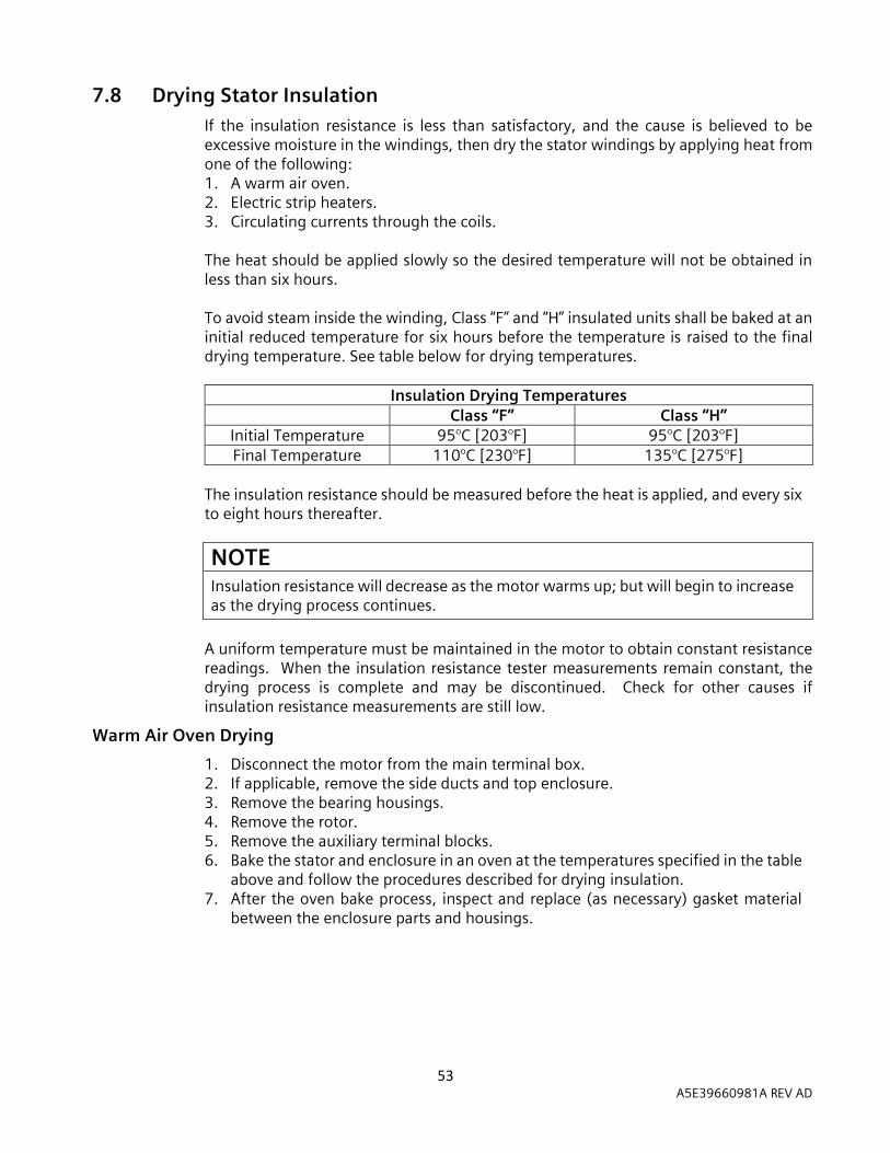
53 A5E39660981A REV AD
7.8 Drying Stator Insulation If the insulation resistance is less than satisfactory, and the cause is believed to be excessive moisture in the windings, then dry the stator windings by applying heat from one of the following: 1. A warm air oven. 2. Electric strip heaters. 3. Circulating currents through the coils.
The heat should be applied slowly so the desired temperature will not be obtained in less than six hours. To avoid steam inside the winding, Class “F” and “H” insulated units shall be baked at an initial reduced temperature for six hours before the temperature is raised to the final drying temperature. See table below for drying temperatures.
Insulation Drying Temperatures Class “F” Class “H”
Initial Temperature 95°C [203°F] 95°C [203°F] Final Temperature 110°C [230°F] 135°C [275°F]
The insulation resistance should be measured before the heat is applied, and every six to eight hours thereafter.
NOTE Insulation resistance will decrease as the motor warms up; but will begin to increase as the drying process continues.
A uniform temperature must be maintained in the motor to obtain constant resistance readings. When the insulation resistance tester measurements remain constant, the drying process is complete and may be discontinued. Check for other causes if insulation resistance measurements are still low.
Warm Air Oven Drying
1. Disconnect the motor from the main terminal box. 2. If applicable, remove the side ducts and top enclosure. 3. Remove the bearing housings. 4. Remove the rotor. 5. Remove the auxiliary terminal blocks. 6. Bake the stator and enclosure in an oven at the temperatures specified in the table
above and follow the procedures described for drying insulation. 7. After the oven bake process, inspect and replace (as necessary) gasket material
between the enclosure parts and housings.
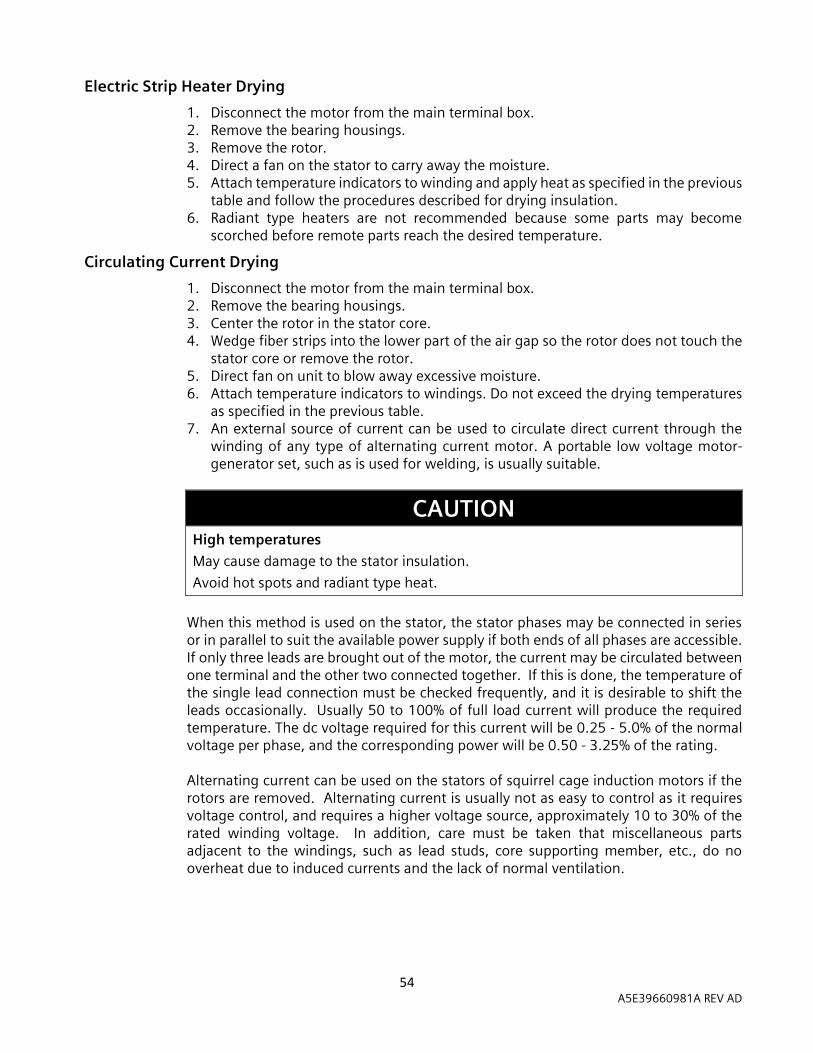
54 A5E39660981A REV AD
Electric Strip Heater Drying
1. Disconnect the motor from the main terminal box. 2. Remove the bearing housings. 3. Remove the rotor. 4. Direct a fan on the stator to carry away the moisture. 5. Attach temperature indicators to winding and apply heat as specified in the previous
table and follow the procedures described for drying insulation. 6. Radiant type heaters are not recommended because some parts may become
scorched before remote parts reach the desired temperature.
Circulating Current Drying
1. Disconnect the motor from the main terminal box. 2. Remove the bearing housings. 3. Center the rotor in the stator core. 4. Wedge fiber strips into the lower part of the air gap so the rotor does not touch the
stator core or remove the rotor. 5. Direct fan on unit to blow away excessive moisture. 6. Attach temperature indicators to windings. Do not exceed the drying temperatures
as specified in the previous table. 7. An external source of current can be used to circulate direct current through the
winding of any type of alternating current motor. A portable low voltage motor-generator set, such as is used for welding, is usually suitable.
CAUTION High temperatures
May cause damage to the stator insulation.
Avoid hot spots and radiant type heat.
When this method is used on the stator, the stator phases may be connected in series or in parallel to suit the available power supply if both ends of all phases are accessible. If only three leads are brought out of the motor, the current may be circulated between one terminal and the other two connected together. If this is done, the temperature of the single lead connection must be checked frequently, and it is desirable to shift the leads occasionally. Usually 50 to 100% of full load current will produce the required temperature. The dc voltage required for this current will be 0.25 - 5.0% of the normal voltage per phase, and the corresponding power will be 0.50 - 3.25% of the rating. Alternating current can be used on the stators of squirrel cage induction motors if the rotors are removed. Alternating current is usually not as easy to control as it requires voltage control, and requires a higher voltage source, approximately 10 to 30% of the rated winding voltage. In addition, care must be taken that miscellaneous parts adjacent to the windings, such as lead studs, core supporting member, etc., do no overheat due to induced currents and the lack of normal ventilation.

55 A5E39660981A REV AD
7.9 Bearing – General Maintenance Long life of bearings is assured by maintaining proper alignment, belt tension, and lubrication at all times. Incorrect alignment of solid and flexible couplings can cause excessive load on the bearings, and excessive vibration and thrust. Misalignment of belt drives can cause thrust or harmful shaft oscillation. Improper alignment of gear drives will produce shock loads and may bend the shaft. Excessive belt tension often causes overheating and failure of bearings. Bearings tend to overheat when pulley centers are too close, pulley diameters are too small, or belt speed is too high.
Bearing Construction
Two types of bearings are employed in induction motors manufactured by Siemens Norwood. These are: 1. Anti-friction bearings. 2. Sleeve bearings. The bearing mounting, supporting structure and housing construction will depend upon the type of bearing. Anti-friction bearing motors have a one-piece bearing bracket, while the sleeve bearing motors have split bearing housings.
Insulated Bearings
One or both bearings may be insulated to prevent common mode voltage and shaft currents from pitting bearing surfaces. The insulation is located at the joint between the bearing housing or bracket and the bearing. Insulated bearings are designated by an instruction plate on the bearing housing. Periodically check that the insulation has not been degraded or destroyed. The bearing insulation can be checked using an ohmmeter or circuit test light. For sleeve bearing motors with one bearing insulated, the shaft must be raised a few mils at the non-drive end of the motor so that it is not in contact with the bearing. The shaft coupling must also be parted so that the shaft is not grounded through the driven equipment. For motors with both bearings insulated, disconnect the bearing grounding strap before testing for insulation integrity. Bearing temperature devices must be disconnected and oil rings must not be in contact with both the shaft and the bearing.
Antifriction Bearings
Antifriction bearings are selected to provide long service life when they are given the proper maintenance. Bearing failure(s) can be caused by too little or too much lubrication, contamination, excessive bearing load, improper installation, alignment, or vibration. The symptoms of antifriction bearing failure are excessive vibration, noise, and excessive heat generation. The races and balls should be periodically inspected for damage. Any damage requires the replacement of the bearing.
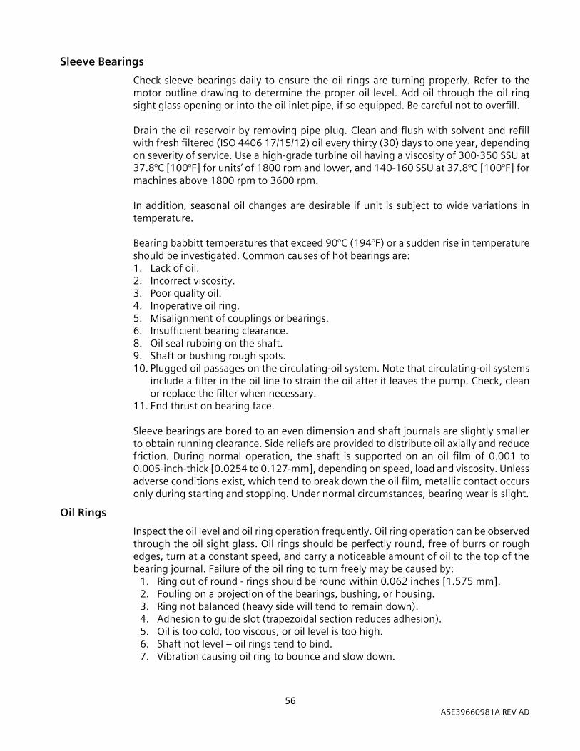
56 A5E39660981A REV AD
Sleeve Bearings
Check sleeve bearings daily to ensure the oil rings are turning properly. Refer to the motor outline drawing to determine the proper oil level. Add oil through the oil ring sight glass opening or into the oil inlet pipe, if so equipped. Be careful not to overfill. Drain the oil reservoir by removing pipe plug. Clean and flush with solvent and refill with fresh filtered (ISO 4406 17/15/12) oil every thirty (30) days to one year, depending on severity of service. Use a high-grade turbine oil having a viscosity of 300-350 SSU at 37.8°C [100°F] for units’ of 1800 rpm and lower, and 140-160 SSU at 37.8°C [100°F] for machines above 1800 rpm to 3600 rpm. In addition, seasonal oil changes are desirable if unit is subject to wide variations in temperature. Bearing babbitt temperatures that exceed 90°C (194°F) or a sudden rise in temperature should be investigated. Common causes of hot bearings are: 1. Lack of oil. 2. Incorrect viscosity. 3. Poor quality oil. 4. Inoperative oil ring. 5. Misalignment of couplings or bearings. 6. Insufficient bearing clearance. 8. Oil seal rubbing on the shaft. 9. Shaft or bushing rough spots. 10. Plugged oil passages on the circulating-oil system. Note that circulating-oil systems
include a filter in the oil line to strain the oil after it leaves the pump. Check, clean or replace the filter when necessary.
11. End thrust on bearing face. Sleeve bearings are bored to an even dimension and shaft journals are slightly smaller to obtain running clearance. Side reliefs are provided to distribute oil axially and reduce friction. During normal operation, the shaft is supported on an oil film of 0.001 to 0.005-inch-thick [0.0254 to 0.127-mm], depending on speed, load and viscosity. Unless adverse conditions exist, which tend to break down the oil film, metallic contact occurs only during starting and stopping. Under normal circumstances, bearing wear is slight.
Oil Rings
Inspect the oil level and oil ring operation frequently. Oil ring operation can be observed through the oil sight glass. Oil rings should be perfectly round, free of burrs or rough edges, turn at a constant speed, and carry a noticeable amount of oil to the top of the bearing journal. Failure of the oil ring to turn freely may be caused by:
1. Ring out of round - rings should be round within 0.062 inches [1.575 mm]. 2. Fouling on a projection of the bearings, bushing, or housing. 3. Ring not balanced (heavy side will tend to remain down). 4. Adhesion to guide slot (trapezoidal section reduces adhesion). 5. Oil is too cold, too viscous, or oil level is too high. 6. Shaft not level – oil rings tend to bind. 7. Vibration causing oil ring to bounce and slow down.

57 A5E39660981A REV AD
At the first sign of oil discoloration or contamination, replace with new oil. Rapid discoloration is caused by bearing wear, often from vibration or thrust. Change oil as required to keep clean. When assembling the bearing, it is possible to foul the rings so that they will not turn freely. Check ring operation by rotating shaft by hand after assembly
Oil Seals
The 580 frame uses fixed labyrinth oil seals to close off the bearing cavity. The oil seals should be centered radially on the shaft and set so that the radial clearance is uniform on all sides. The 500, 880, SH400, SH450 and SH560 frames use floating-type oil seals that can accommodate small radial movements in the shaft. These floating labyrinth seals should be free to move radially in the bearing housing. A jammed seal could lead to a bearing overheating and poor vibration due to excessive seal rubbing during operation. The primary purposes of the oil seals are: 1. To prevent the entrance of dirt or debris from entering the bearing cavity. 2. To retain the oil in the bearing cavity. 3. To provide pressure regulation in the bearing cavity. To achieve these purposes, it is necessary that a specific diametrical clearance of the oil seal to shaft be held. The cooling fans of the motor tend to create suction or pressure in the bearing cavity, which, if large enough, will push or draw oil mist out along the shaft. The closed fitting oil seal serves as a barrier against excessive pressure or suction inside the bearing.
Standard Oil Seal Clearances
Frame Diametrical Clearance (in) Diametrical Clearance (mm)
500 0.008 to 0.014 0.203 to 0.356
580 0.008 to 0.014 0.203 to 0.356
880 0.003 to 0.008 0.076 to 0.203
SH400 0.003 to 0.008 0.076 to 0.203
SH450 0.003 to 0.008 0.076 to 0.203
SH560 0.003 to 0.008 0.076 to 0.203
Some of the bearing cavities and oil seals are vented to the outside air in order to keep the bearing cavity pressure as close to atmospheric as possible. For these designs, it is important that the piping and venting for these oil seals be kept clean.
NOTE When a sleeve bearing becomes worn and requires replacement, the labyrinth oil seal should also be replaced.

58 A5E39660981A REV AD
NOTE Floating type oil seals general do not need to be addressed doing a normal maintenance cycle. If maintenance is required contact Siemens Service or a local EASA repair facility.
Bearing Clearance Too Large
The clearance between the journal and the bearing will permit the journal center to be slightly below the bearing center. With the motor operating, the presence of the oil film between the journal and the bearing will cause the shaft to rise slightly. Too large of a bearing clearance or clogged oil return holes in the bearing will permit excessive oil to seep out the ends of the bearing. This seepage, combined with the rotation of the shaft, will create an oil mist inside the bearing cavity that will tend to leak through the oil seals. Excessive pressure in a force feed lubrication system can also cause an oil mist to build up.
Cavity Pressures
Motors are sensitive to the amount of pressure or vacuum existing in the bearing cavity. The table below shows the maximum allowable oil cavity pressure or vacuum in terms of plus or minus inches of H2O:
Frame Size Drive End Non-drive End 500 ± 0.12 +3.00, -0.12 580 ± 0.12 +3.00, -0.12 880 ± 0.12 ± 0.50
SH400 ± 0.12 ± 0.50 SH450 ± 0.12 ± 0.50 SH560 ± 0.12 ± 0.50
For the correction of a high or low reading it is important that: 1. The parts and joints around the bearing cavity and oil seals are sealed. 2. Condensation drains, piping, sight gauges and breathers are functioning properly. 3. Auxiliary equipment extending into the motor must be properly sealed to prevent a
transfer of air from inside to outside the motor.

59 A5E39660981A REV AD
Sealing Parts
Even though joints may seem to match perfectly, minute clearances exist through which oil may leak. Sealant should be applied to the mating surfaces of parts where oil is present to prevent seepage. Apply sealant as follows: 1. Surfaces shall be clean of dirt, grease, and oil sealant. Use a non-oil base solvent if
necessary. 2. The mating surfaces should be flat with no nicks or burrs raised above the surface.
There should be no gap when the mating surfaces are together. Remove all excess paint from the parting line surfaces and degrease thoroughly. Do no grind the mating surfaces.
3a. For 449, S449, 500, 880, SH400, SH450 and SH560 frames, apply a small bead of silicone RTV at the bearing housing parting surfaces. Loctite 518 may be used in replace of RTV in environments where silicon is prohibited. Do not apply too much sealant as excess will be squeezed out and get into labyrinth seals, bearing, oil cavities, etc. Apply a uniform, thin layer (about 0.05" thick) of CURIL-T* to the floating oil seal surfaces that mate with the bearing housing. Allow CURIL-T* to cure on the seals for 15 minutes before insertion into bearing housing.
3b. For the 580 frame, apply a small bead of silicone RTV to all mating surfaces of parts where oil is present, including fixed oil seals and bearing housing parting lines.
4. Assemble parts. *CURIL-T may be ordered through Siemens Customer Service in Norwood, Ohio. Part number 53-688-487-001 should be used for ordering purposes.
7.10 Bearing – Lubrication
Grease Lubricated Anti-Friction Bearings
NOTE
A common mistake is over-lubrication of bearings. When grease is added without removing the drain plug, the excess grease may be forced into and through the inner bearing cap and thrown on to the windings. If bearing is over-lubricated, bearing could run hot, and may lead to failure.
All anti-friction bearing motors will have an affixed plate with lubricating instructions. The instructions on this plate should be followed to achieve the optimum bearing life and to avoid consequential damage to the rotating parts. The frequency of re-lubricating the bearings depends on multiple factors including speed, type of bearing, service, operating equipment, and application.
Siemens recommends following the grease, grease quantities, and grease re-lubrication intervals specified on the lube plate attached to motor. The severity of service may require increased re-lubrication intervals. Greases should not be combined or mixed. Siemens does not recommend mixing two greases even if compatible of the two greases has been verified. The common greases and associated characteristics can be found in the subsequent table.
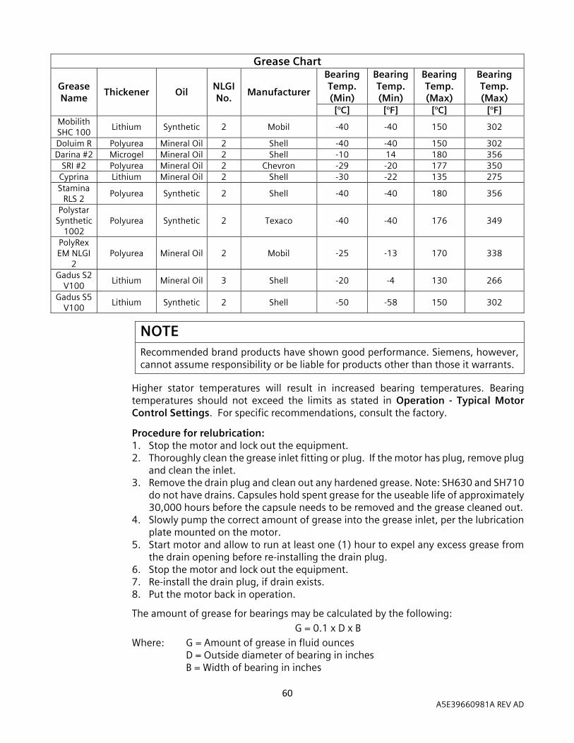
60 A5E39660981A REV AD
Grease Chart
Grease Name
Thickener Oil NLGI No.
Manufacturer
Bearing Temp. (Min)
Bearing Temp. (Min)
Bearing Temp. (Max)
Bearing Temp. (Max)
[°C] [°F] [°C] [°F] Mobilith SHC 100
Lithium Synthetic 2 Mobil -40 -40 150 302
Doluim R Polyurea Mineral Oil 2 Shell -40 -40 150 302
Darina #2 Microgel Mineral Oil 2 Shell -10 14 180 356
SRI #2 Polyurea Mineral Oil 2 Chevron -29 -20 177 350
Cyprina Lithium Mineral Oil 2 Shell -30 -22 135 275
Stamina RLS 2
Polyurea Synthetic 2 Shell -40 -40 180 356
Polystar Synthetic
1002 Polyurea Synthetic 2 Texaco -40 -40 176 349
PolyRex EM NLGI
2 Polyurea Mineral Oil 2 Mobil -25 -13 170 338
Gadus S2 V100
Lithium Mineral Oil 3 Shell -20 -4 130 266
Gadus S5 V100
Lithium Synthetic 2 Shell -50 -58 150 302
NOTE
Recommended brand products have shown good performance. Siemens, however, cannot assume responsibility or be liable for products other than those it warrants.
Higher stator temperatures will result in increased bearing temperatures. Bearing temperatures should not exceed the limits as stated in Operation - Typical Motor Control Settings. For specific recommendations, consult the factory.
Procedure for relubrication: 1. Stop the motor and lock out the equipment. 2. Thoroughly clean the grease inlet fitting or plug. If the motor has plug, remove plug
and clean the inlet. 3. Remove the drain plug and clean out any hardened grease. Note: SH630 and SH710
do not have drains. Capsules hold spent grease for the useable life of approximately 30,000 hours before the capsule needs to be removed and the grease cleaned out.
4. Slowly pump the correct amount of grease into the grease inlet, per the lubrication plate mounted on the motor.
5. Start motor and allow to run at least one (1) hour to expel any excess grease from the drain opening before re-installing the drain plug.
6. Stop the motor and lock out the equipment. 7. Re-install the drain plug, if drain exists. 8. Put the motor back in operation.
The amount of grease for bearings may be calculated by the following:
G = 0.1 x D x B
Where: G = Amount of grease in fluid ounces D = Outside diameter of bearing in inches B = Width of bearing in inches
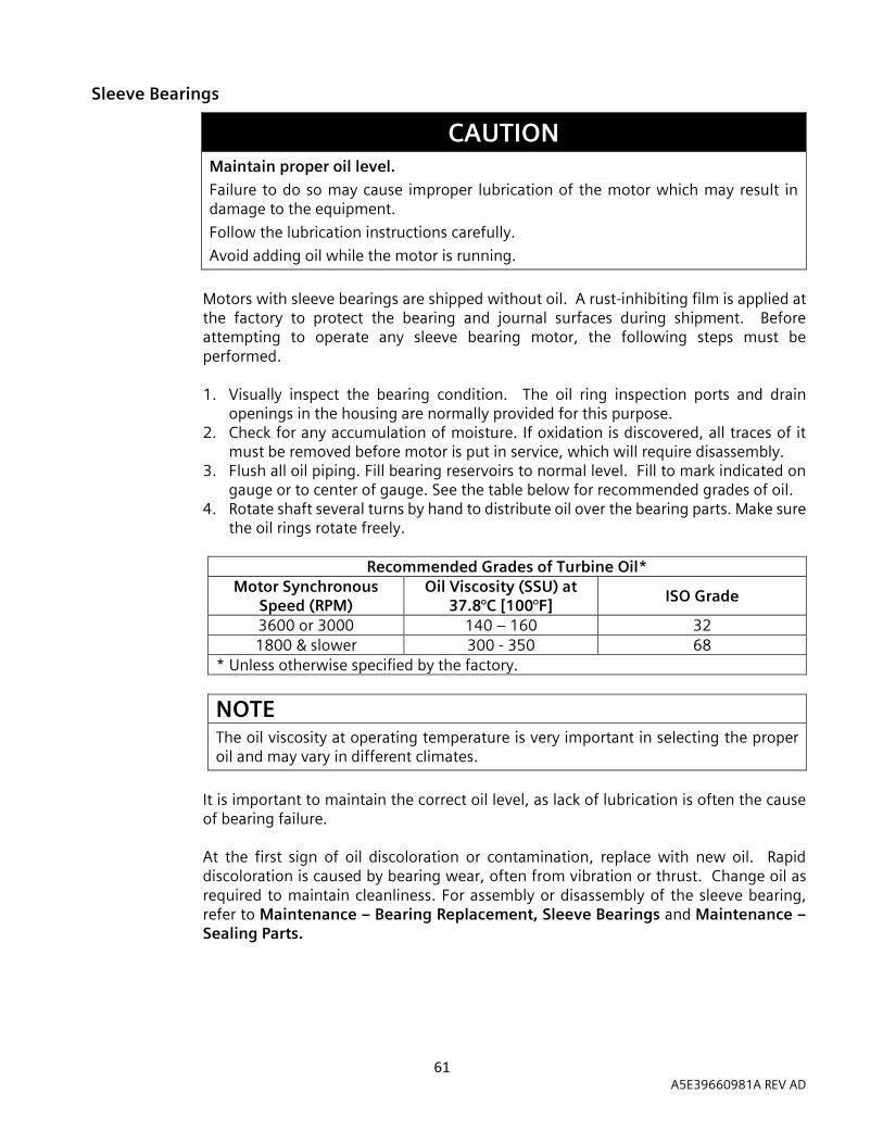
61 A5E39660981A REV AD
Sleeve Bearings
CAUTION Maintain proper oil level.
Failure to do so may cause improper lubrication of the motor which may result in damage to the equipment.
Follow the lubrication instructions carefully.
Avoid adding oil while the motor is running.
Motors with sleeve bearings are shipped without oil. A rust-inhibiting film is applied at the factory to protect the bearing and journal surfaces during shipment. Before attempting to operate any sleeve bearing motor, the following steps must be performed. 1. Visually inspect the bearing condition. The oil ring inspection ports and drain
openings in the housing are normally provided for this purpose. 2. Check for any accumulation of moisture. If oxidation is discovered, all traces of it
must be removed before motor is put in service, which will require disassembly. 3. Flush all oil piping. Fill bearing reservoirs to normal level. Fill to mark indicated on
gauge or to center of gauge. See the table below for recommended grades of oil. 4. Rotate shaft several turns by hand to distribute oil over the bearing parts. Make sure
the oil rings rotate freely.
Recommended Grades of Turbine Oil* Motor Synchronous
Speed (RPM) Oil Viscosity (SSU) at
37.8°C [100°F] ISO Grade
3600 or 3000 140 – 160 32 1800 & slower 300 - 350 68
* Unless otherwise specified by the factory.
NOTE The oil viscosity at operating temperature is very important in selecting the proper oil and may vary in different climates.
It is important to maintain the correct oil level, as lack of lubrication is often the cause of bearing failure. At the first sign of oil discoloration or contamination, replace with new oil. Rapid discoloration is caused by bearing wear, often from vibration or thrust. Change oil as required to maintain cleanliness. For assembly or disassembly of the sleeve bearing, refer to Maintenance – Bearing Replacement, Sleeve Bearings and Maintenance – Sealing Parts.

62 A5E39660981A REV AD
Force Feed Lubrication
Oil is metered through an orifice in oil inlet line to allow the proper amount of lubricating oil to enter the bearing. Conventional oil rings are also supplied with the motor to ensure temporary bearing lubrication in the event the force feed oil supply should fail. It is important to check oil flow frequently. Lack of lubrication may cause a bearing failure. The SH710 frame, 2 pole (3600 RPM at 60Hz) motors do not have oil rings.
Checking Sleeve Bearing Clearance
Excessive clearance can cause rapid bearing failure, and a decreased air gap between the stator and the rotor at the bottom of the motor. Diametrical sleeve bearing clearances for the 500 and 580 frame motors are approximately 1.7-2.7 mils per inch of the bearing diameter. Diametrical sleeve bearing clearances for the 880, SH400, SH450 and SH560 frame motors are approximately 1.0-2.0 mils per inch of the bearing diameter. An accurate check of the bearing clearance is obtained with micrometer measurements of the shaft journal and the bearing bore.
7.11 Bearing - Replacement
Antifriction Bearings
For the typical anti-friction bearing configuration, refer to Figure 7-1, 7-2 & 7-3.
Replacement bearings may be of a different manufacturer but must be equal to the originals used in the motor. When ordering bearings specify the following: 1. The complete A.F.B.M.A. (Anti-Friction Bearing Manufacturers’ Association) bearing
number from the motor nameplate. 2. Identifying numerals and manufacturer stamped on the bearing. 3. Bearing tolerance class, i.e. - A.B.E.C.-1 (Annular Bearing Engineers’ Committee
Tolerance Class One). 4. Internal radial clearance, i.e. – A.F.B.M.A.-3 (Clearance Class Three). 5. Electric motor quality.
Replace Antifriction Bearings
1. Remove the bolts holding the end caps to the housings. 2. Remove the bolts holding the bearing housings to the yoke. 3. Remove the bearing housings. 4. Remove the bearing(s) with a puller. Refer to Figure 7-4. 5. Check the shaft and housing diameter for proper size with a micrometer. 6. Heat the new bearing in an oven at 93.3°C [200°F] or (preferred) by placing the new
bearing on an induction heater and allowing it to reach the bearing manufacturer’s recommended temperature. While it’s hot, slide the bearing onto the shaft and make certain that the inner race makes firm even contact with shaft shoulder and hold until it locks into place. Do not subject the bearing to impacts. NEVER HEAT A BEARING TO A TEMPERATURE GREATER THAN 123.9°C [255°F].
7. After the bearing has cooled, pack the bearing caps with the proper grease. 8. Reassemble the housings and end caps.

63 A5E39660981A REV AD
The quantity of grease used when re-packing a bearing after cleaning or a replacement is shown in the table below:
Type of Bearing Operating
Bearing (Shaft) Grease Quantity* (End Caps) Outer Inner
Deep Groove Ball Horizontal 2/3 Full 1/3 Full Roller Horizontal 1/3 Full 1/3 Full
* Pack all open bearings full between balls or rollers but remove excess grease on the outside of the retainers.
Figure 7.1 – Typical anti-friction bearing configuration for 449, S449, 500, 580 &
SH400 Frames.
Figure 7.2 – Typical anti-friction bearing configuration for 880 & SH450 Frames.

64 A5E39660981A REV AD
Figure 7.3 – Typical anti-friction bearing configuration for the SH560 Frame.
NOTE For optimal results, the seal should be positioned flush with the outer-most bearing housing surface. Some frame sizes have a shaft seal on only one end of the motor.
Protect the shaft end with a cap. If the bearing is reusable, make certain the puller applies pressure against the bearing inner race only. If the puller will not hook the bearing inner race, fabricate a split bushing and install it between the bearing and the puller hooks.
Figure 7.4 – Removing the anti-friction bearing with a puller.

65 A5E39660981A REV AD
Sleeve Bearings
When replacing sleeve bearings, it is always desirable to check the fit (contact pattern) of the bearing to the shaft. When ordering sleeve bearings, be sure to provide complete motor nameplate and bearing data. If the bearing is insulated, be sure to replace it with another insulated bearing. Whenever a bearing is replaced, cleanliness must be observed through every step of the operation. Always inspect the bearing journal surfaces; they must be smooth and polished. Slight scoring can be removed with crocus cloth. If the motor shaft has been seriously scored it must be put between centers and reground. Journals can be ground 0.001 inch [0.0254 mm] under size, but they must be round and concentric with shaft center.
Sleeve Bearing Replacement
The replacement of sleeve bearings can often be accomplished without uncoupling the load or otherwise disturbing the installation.
500 Frame (Figure 7.5)
1. Check replacement bearings for nicks or shipping damage. Do not scrape. 2. Remove the upper half of the bearing bracket. 3. Carefully remove the top half of the bearing capsule by first lifting straight up, then
pulling away from the bearing area. 4. Remove the top half of the sleeve bearing. 5. Remove the bearing temperature probes if so equipped. 6. Displace the oil rings axially away from the bottom half of the sleeve bearing. 7. Raise the shaft slightly and support it in that position. 8. Rotate the lower bearing half 180° and remove the lower half of the bearing
bushing. 9. Reassemble by reversing the steps above. Apply sealant. The side faces of the
labyrinth seals must be sealed with CURIL-T or equivalent non-hardening sealing compound. Be careful not to disturb or jam the seals when replacing the upper half of the bearing capsule. Refer to Maintenance – Bearing – General Maintenance, Sealing Parts for the proper sealing procedure of this bearing design.
10. Lubricate. Turn the shaft by hand to ensure the proper fit and oil ring operation. 11. Start motor without load and check oil ring operation.
Figure 7.5 – Typical sleeve bearing construction with floating type oil seals (500 Frame).

66 A5E39660981A REV AD
580 Frame (Figure 7.6)
1. Check replacement bearings for nicks or shipping damage. Do not scrape. 2. Loosen the outer oil seal and remove. 3. Remove the two long bolts (at approximately 2:00 and 10:00 o’clock positions) that
go through the inner oil seal. 4. Remove the upper half of the bearing capsule. 5. Remove the top half of the sleeve bearing. 6. Remove the bearing temperature probes if so equipped. 7. Displace the oil rings axially away from the bottom half of the sleeve bearing. 8. Raise the shaft slightly and support it in that position. 9. Rotate the lower bearing half 180° and remove the lower half of the bearing. 10. Reassemble by reversing the steps above. Refer to Maintenance – Bearing –
General Maintenance, Sealing Parts for the proper sealing procedure of this bearing design.
11. Lubricate. Turn the shaft by hand to ensure the proper fit and oil ring operation. 12. Start the motor without load and check the oil ring operation.
Figure 7.6 – Typical sleeve bearing construction with labyrinth type oil seals (580 Frame).

67 A5E39660981A REV AD
Sleeve Bearing 880, SH400, SH450 & SH560 Frames (See Figure 7.7)
1. Check replacement bearings for nicks or shipping damage. Do not scrape. 2. Carefully remove the bearing housing cap by first lifting straight up, then pulling
away from the bearing area. 3. Remove the top half of the bearing liner. 4. Remove the bolts at the split line of the oil ring. 5. Remove the bearing temperature probes if so equipped. 6. Raise the shaft slightly and support it in that position. 7. Rotate the lower bearing half 180° and remove the lower half of the bearing liner. 8. Reassemble by reversing the steps above. Apply sealant. The side faces of the
labyrinth seals must be sealed with CURIL-T or equivalent non-hardening sealing compound. Be careful not to disturb or jam the seals when replacing the upper half of the bearing capsule. Refer to Maintenance – Bearing – General Maintenance, Sealing Parts for the proper sealing procedure of this bearing design.
9. Lubricate. Turn the shaft by hand to ensure the proper fit and oil ring operation. 10. Start motor without load and check oil ring operation.
Figure 7.7 – Typical sleeve bearing construction for 880, SH 400, SH450 & SH560
Frames.
68 A5E39660981A REV AD
End Float – Sleeve Bearings
Control of the rotor end float in sleeve bearing motors is maintained in the drive end bearing. The total end float for all frames is 0.5 inches [12.7 mm].
On the 500 and 580 frames, the bearings are located axially by shims between the bearing bushing and the bearing capsule shoulders. On the 880, SH400, SH450 and SH560, the shims are located between the bearing housing mounting flange and the bearing bracket. The shims permit the bearing to be adjusted axially to maintain coincidence of electrical and mechanical center. Any adjustment of the axial position of one bearing should be accompanied by the same axial adjustment of the opposite end bearing.
The coupling should limit the end float of the shaft to ± 0.18 inches [4.572 mm] from the mechanical center. The limited end float coupling prevents the rotor from rubbing against the bearing shoulders during operation.
7.12 Paint Maintenance Siemens applies a robust protective paint coating on the machine. If the paint layer is broken and touch-up is required (for example around bolt heads or bearing lubrication areas after maintenance activity), remove any loose flaking paint, clean the area thoroughly using a detergent or organic solvent, then apply a touch-up coating with a performance level that is chosen to meet or exceed the environmental demands (such as humidity and presence of salt spray). The coatings applied to the motor at the factory are fully crosslinked epoxy or polyurethane products and are generally universally compatible with other coatings that may be used for touch-up.
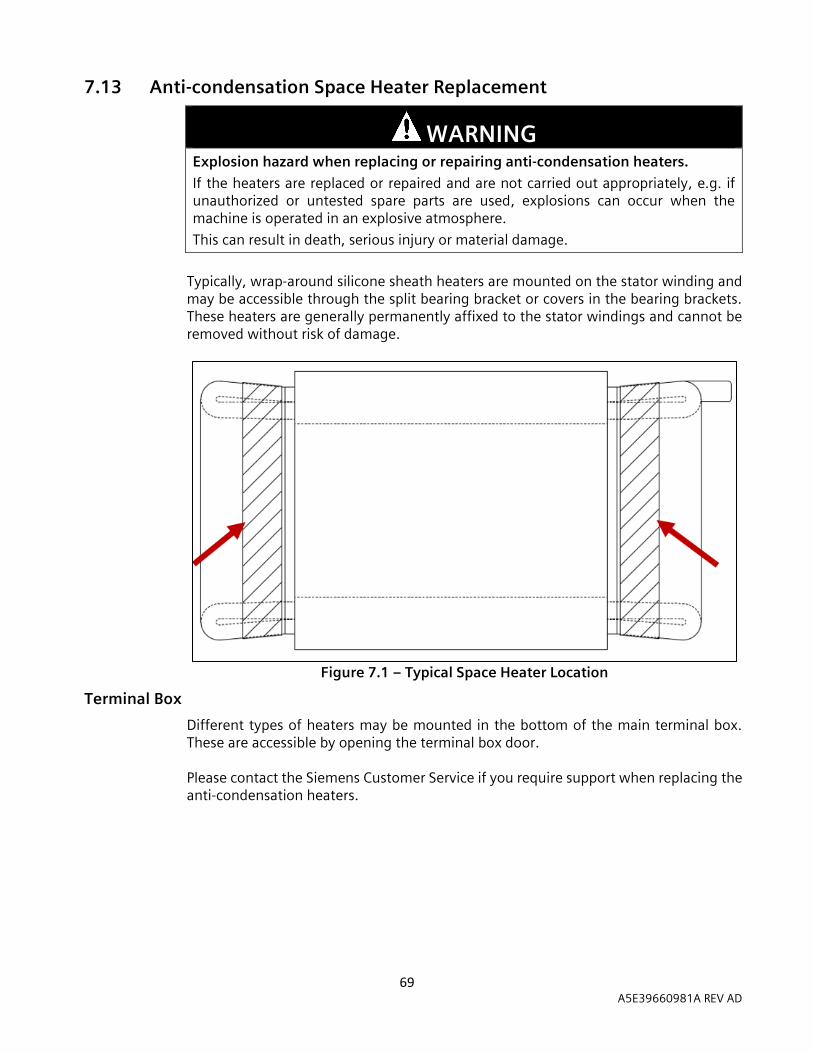
69 A5E39660981A REV AD
7.13 Anti-condensation Space Heater Replacement
WARNING
Explosion hazard when replacing or repairing anti-condensation heaters.
If the heaters are replaced or repaired and are not carried out appropriately, e.g. if unauthorized or untested spare parts are used, explosions can occur when the machine is operated in an explosive atmosphere.
This can result in death, serious injury or material damage.
Typically, wrap-around silicone sheath heaters are mounted on the stator winding and may be accessible through the split bearing bracket or covers in the bearing brackets. These heaters are generally permanently affixed to the stator windings and cannot be removed without risk of damage.
Figure 7.1 – Typical Space Heater Location
Terminal Box
Different types of heaters may be mounted in the bottom of the main terminal box. These are accessible by opening the terminal box door.
Please contact the Siemens Customer Service if you require support when replacing the anti-condensation heaters.
70 A5E39660981A REV AD
8 Storage 8 8.1 General Information
If the machine is not installed and operated soon after delivery, the motor can be temporarily stored in a clean, dry, well-ventilated location, free from ambient vibration and rapid or wide variations of temperature. Indoor storage locations are recommended. Consider a motor in long-term storage when one of the following conditions apply: 1. The motor has been delivered to the end user and is awaiting installation for more
than 30 days. 2. The motor has been installed but operation is delayed for 30 days (or more) pending
completion of the plant construction or application setup. 3. The motor is installed and experiences long periods (≥30 days) of operating cycles. 4. The plant or application is shut down for 30 days or more.
CAUTION Thermal damage.
If the motor is boxed or covered in anyway and the space heaters are energized, there should be thermostatic control and proper observation to detect an over-temperature condition quickly.
Ensure that all temporary packaging does not contact the space heaters.
CAUTION Extreme cold or temperature changes.
During periods of extreme cold or temperature changes, the space heaters (if equipped) may not be able to provide enough heat to completely prevent condensation and freezing critical parts. If a period of storage or disuse will coincide with extreme winter conditions, it is recommended that supplementary heating be used to prevent moisture condensation and freezing.
The stator winding insulation may be permanently damaged by freezing.
CAUTION Extreme temperatures.
Extreme temperatures during storage periods can accelerate the aging of gasketing materials and reduce the service life. Deteriorated gaskets can result in increased risk of gas and particulate ingress into the motor enclosure, frame, and terminal boxes.
Accessories and sensors exposed to extreme temperatures during storage periods may be permanently damaged resulting in abnormal function.

71 A5E39660981A REV AD
NOTE When a motor’s temperature is equal to and below the ambient temperature, water vapor can condense on and within the motor and may promote rapid deterioration. Prevent this by energizing the space heaters to keep the motor internal temperature above the ambient temperature by at least 5.5℃ (10°F).
NOTE It is recommended that motors be stored in a location with temperatures between 4.5℃ (40°F) and 60℃ (140°F) with humidity levels below 50% and minimal exposure to UV light.
NOTE Rodents and other small animals in search of warm surroundings or food sometimes may house inside motors. In some cases, they may damage the insulation materials. Their access to the motor should be prevented.
8.2 Long-Term Storage For long term storage (30 days or more), please review the requirements for each of the installation locations.
Indoor Storage – Wholly Controlled
When a motor is stored in a controlled indoor environment: - Maintain a uniform temperature between 4.5°C (40°F) and 60°C (140°F)
throughout the room or structure while maintaining at least 5.5°C (10°F) above the dew point temperature.
- The relative humidity should be 50% or less. - Dust accumulation should be minimal and no harmful fumes present. - Ensure ambient vibration is less than 0.01 inches/sec, 0-peak.
Indoor Storage – Partially Controlled
When a motor is stored in a partially controlled environment: - The room or enclosure selected should be as clean and dry as possible. - Ensure ambient vibration is less than 0.01 inches/sec, 0-peak. - If the ambient temperature exceeds 60°C (140°F), the space or structure should be
enclosed but well ventilated. - If the ambient temperature is below 4.5°C (40°F), the space heaters should be
energized. If the motor is not equipped with space heaters, consult the factory for the proper size of external space heaters.
- If the relative humidity is more than 50% or there are large daily temperature swings, the space heaters should be energized. If the motors are not equipped with space heaters, the entire motor can be encased in a strong transparent plastic bag. Before sealing the bag, a moisture indicator should be attached to the side of the motor and several bags of silica gel desiccant should be placed around the motor. When the moisture indicator shows that the desiccant has lost its effectiveness, the desiccant bags should be replaced and the plastic bag re-sealed.

72 A5E39660981A REV AD
Outdoor Storage
The motor may be stored outdoors however must be protected for the unique environment to prevent issues. The outdoor storage locations are defined as: - Inland Dry Climate – dust, sand and occasional rain or snow. - Inland Humid Climate (non-industrial) – dust, rain, snow and organic growth
(fungus). - Salty Coastline and Industrial Locations – moisture impregnated with salts or
other chemicals, salty dust rain, snow, organic growth (fungus), fumes, coal and chemical soot.
When a motor is stored outdoors: - Cover the motor completely to protect it from dirt, dust, moisture and other foreign
materials. A shed or other temporary structure is recommended to provide optimal protection for the motor from direct rain, snow and excessive direct sun heat. At a bare minimum, a heavy waterproof cover or tarpaulin should be placed over the motor but should not contact the surfaces of the equipment. Otherwise air circulation under the stored items will be prevented.
- The covering should protect the motor from any flying debris or other damage from high winds.
- Ensure ambient vibration is less than 0.01 inches/sec, 0-peak. - If the ambient temperature exceeds 60°C (140°F), the motor under the cover
should be well ventilated. - The space heaters should be energized. If the motor is not equipped with space
heaters, consult the factory for the proper size of external space heaters for an enclosed shed or temporary structure.
- If the motors are not equipped with space heaters and not protected by an enclosed structure, the entire motor can be encased in a strong transparent plastic bag. Before sealing the bag, a moisture indicator should be attached to the side of the motor and several bags of silica gel desiccant should be placed around the motor. When the moisture indicator shows that the desiccant has lost its effectiveness, the desiccant bags should be replaced and the plastic bag re-sealed.
73 A5E39660981A REV AD
8.3 Preparation for Storage
WARNING Moisture
Can cause damage to the stator windings and bearings.
Protect the motor from moisture.
Sleeve and Tilting Pad Bearings
Motors equipped with sleeve or tilted pad bearings are shipped without lubricating oil. A film of rust-inhibiting oil from the factory protects the bearings and shaft journals during shipment, but this protection does not last for extended periods of storage. Therefore, before placing the motor in storage for longer than one (1) month, fill the oil wells (sumps) to the specified running oil level with a high grade of rust inhibiting turbine oil with the proper viscosity. Remove any shaft blocking on the motors with sleeve bearings to permit rotating the shaft. Do not remove the blocking on motors with tilting pad bearings unless a circulating-oil flood lubricating system is available for use during storage maintenance.
Oil Lubricated Antifriction and Kingsbury Type Bearings
Motors equipped with oil lubricated anti-friction bearings or Kingsbury Type bearings are shipped without lubricating oil. A film of rust-inhibiting oil from the factory protects the bearings and shaft journals during shipment, but this protection does not last for extended periods of storage.
For 3000-3600 RPM (2 pole) vertical motors bearing storage preparation depends on if the motor can be operated during storage. If the motor can be operated, fill the oil wells (sumps) to the proper running level with a high grade of rust-inhibiting turbine oil of the proper viscosity. If the motor will not be run, arrange the motor so it can be disassembled for coating the bearings internal parts with oil. For 1800 RPM and slower (4 pole and slower) vertical motors are designed so the oil completely covers the bearing when properly lubricated. To protect the motor for storage, fill the oil wells (sumps) to the proper running level with a high grade of rust-inhibiting turbine oil of the proper viscosity.
Grease Lubricated Anti-Friction Bearings
Motors equipped with grease lubricated ball or roller bearings are shipped from the factory with the bearings properly packed with grease. If the storage duration from the date of shipment is less than three (3) months, no further preparation is required. If the motor is in storage for over three (3) months, add grease to each bearing. Refer to the lubrication plate on the motor for the grease type and quantity installed at the factory. Use the same or compatible grease. Refer to Maintenance – Bearing – Lubrication and Storage – Storage Maintenance.

74 A5E39660981A REV AD
Oil Mist Lubricated Anti-Friction Bearings
Motors equipped with oil mist lubricated anti-friction bearings require special attention. Check for the tag attached to the motor and read and follow the caution statements on the tag. If the tag states the motor was shipped with grease in the bearings, the motor can be treated the same as grease lubricated anti-friction bearings. If the tag states that an oil mist lubrication system must be connected before the motor is started, then outdoor storage is not permitted, and the motor must be connected to an auxiliary oil-mist system within two weeks of shipment from the factory and operated.
Shaft Extensions and Exposed Machined Surfaces
Shaft extensions and exposed machine surfaces should be coated with an easily removable rust preventive such as Tectyl No. 502-C. If the storage period will be nine months or more and the risk of exposure to moisture is present, take the following precautions: 1. Disassemble the motor taking ensuring not to contaminate the existing lubricant,
bearing, or shaft journal. 2. If any exposed machined surfaces are unpainted, coat these with a non-hardening
protective film, such as Tectyl No. 506. Do not apply this coating to bearings, shaft journals or other parts within the bearing cavity. The coating can be removed using petroleum solvents. Refer Maintenance – Cleaning – Bearing and Housing.
3. If the motor is stored outdoors in an Inland Humid Climate (non-industrial) or Salty Coastline and Industrial Location and before re-assembling the motor, it is recommended to spray all internal surfaces of the stator (winding and iron) with one coat of an anti-fungus varnish (such as P.D. George No. 1137 protective sealer).
8.4 Storage Maintenance While in storage the motor requires maintenance at regular intervals such as rotating the shaft and re-lubricating the bearings to retard oxidation or corrosion and to prevent false brinelling.
Sleeve Bearings
If the motor is equipped with sleeve bearings, the shaft should be rotated per the table below. The shaft can be manually rotated by hand at approximately 30 rpm for 15 seconds or if power is available, the motor can be electrically bumped for 5 seconds.
Storage Environment Shaft Rotation Frequency
Indoor Wholly Controlled Every two (2) months
Partially Controlled Once per month
Outdoor
Inland Dry Climate Once per month
Inland Humid Climate Once per week
Salty Coastline and Industrial Location Once per week

75 A5E39660981A REV AD
Tilting Pad Bearings
If the motor is equipped with tilted pad bearings, outdoor storage is not permitted. Do not rotate the shaft unless the motor is connected to the external flood lubrication system and is in operation. If circulating-oil system is not available, do not run the motor. Every three (3) months disassemble the motor for access to the bearings and coat the bearings and the shaft journal area with a rust-inhibiting turbine oil of the proper viscosity.
Oil Lubricated Antifriction and Kingsbury Type Bearings
If the motor is equipped with oil-lubricated anti-friction bearings or Kingsbury Type bearings, confirm the rated speed from the main nameplate or motor outline drawing. For 3000-3600 RPM (2 pole) vertical motors, every three (3) months, run the motor for two minutes to recoat the oil-lubricated bearings. If the motor cannot be run, it must be partially disassembled to reach the bearings to manually cover the bearing with a fresh coat of oil. For 1800 RPM and slower (4 pole and slower) vertical motors, every two (2) months, the shaft should be rotated. Manually turn it by hand at about 30 rpm for 15 seconds or if power is available, the motor can be electrically bumped for 5 seconds.
Grease Lubricated Anti-Friction Bearings
If the motor is equipped with grease lubricated anti-friction bearings, the motor shaft should be rotated per the table below. The shaft can be manually rotated by hand at approximately 30 rpm for 15 seconds or if power is available, the motor can be electrically bumped for 5 seconds.
Storage Environment Shaft Rotation Frequency
Indoor Wholly Controlled Every two (2) months
Partially Controlled Once per month
Outdoor
Inland Dry Climate Once per month
Inland Humid Climate Once per week
Salty Coastline and Industrial Location Once per week
The bearings should be re-greased at one (1) year intervals while in storage. Refer to the lubrication plate on the motor for the grease type and quantity used at the factory. Use the same or a compatible grease. Refer to Maintenance – Bearing – Lubrication.
Oil Mist Lubricated Anti-Friction Bearings
For protection, the motor was shipped with grease in the bearings, if desired for storage follow the instructions for grease lubricated anti-friction bearings described above. If motor does not have grease in the bearings, start the oil mist system connected during the storage preparations, start the motor, and run it for two minutes. Repeat this process every two weeks.
76 A5E39660981A REV AD
Shaft Extensions, Exposed Machined Surfaces and Flanges
Check the condition of the rust inhibitor applied and recoat as recommended by the manufacturer. For example, Tectyl No. 502-C, heavily applied, may last approximately 2 years.
Other
If spare heaters are being used, check that they are operating properly. Perform this inspection every time the bearings are maintained. Desiccant bags and plugs must be checked and replaced periodically. In cases where the humidity is high (above 50% relative humidity) and the temperature drops often, the desiccant may have to be replaced weekly. Every two (2) years while in storage, the motor should be disassembled, inspected, cleaned and prepared for storage again.
Recommended Storage Maintenance Products
Tectyl 502-C and 506 Valvoline Oil Co. Div. of Ashland and Refining Co. 150 Fourth Avenue Freedom, PA 15042 P.D. George Insulation Manufacturers Corp. 1231 Superior Avenue, N.E. Cleveland, OH 44114
NOTE
Recommended brand products have shown good performance. Siemens Energy & Automation, Inc. however, cannot assume responsibility or be liable for products other than those it warrants.
8.5 Preparation for Service After the motor has been subjected to a storage period, please perform the following: 1. Remove all storage materials from the motor (i.e. plastic wrap, desiccant, moisture
indicators, etc.) 2. Perform the steps included in Installation – Preparation for Service. 3. Perform the steps included in Maintenance – Testing – Insulation Resistance and
Polarization Index.
77 A5E39660981A REV AD
9 Disposal 9 Protecting the environment and preserving its resources are corporate goals of the highest priority for Siemens. Our worldwide environmental management system to ISO 14001 ensures compliance with legislation and sets high standards in this regard. Environmentally friendly design, technical safety and health protection are always firm goals even at the product development stage. Recommendations for the environmentally friendly disposal of the machine and its components are given in the following section. Be sure to comply with local disposal regulations.
9.1 RoHS – Restricting the use of certain Hazardous Substances In compliance with RoHS ("Restriction of certain Hazardous Substances”) we replace substances that are damaging to the environment by those that are not based on state-of-the art technology. In doing so, safety in operation and handling will take priority at all times.
NOTE Country-specific legislation
When disposing the machine or waste that is created during the individual phases of its life cycle, please observe the statutory requirements applicable in the country of use.
9.2 Dismantling the Machine Disassemble the machine using the instruction in this manual or with general procedures commonly used.
WARNING
Machine parts can fall
The machine is made up of heavy parts. These parts are liable to fall during dismantling. This can result in death, serious injury or material damage.
Before you release any machine parts, secure them so that they cannot fall.

78 A5E39660981A REV AD
9.3 Disposal of Material
Components
The machines consist mainly of steel and various proportions of copper and aluminum. Metals are generally considered to be unlimitedly recyclable.
Process Materials and Chemicals
Sort the process materials and chemicals for recycling, for example: oil, grease, cleaning substances and solvents, paint, etc. Dispose of the separated components according to local regulations or via a specialist disposal company. The same applies for cloths and cleaning substances which have been used while working on the motor.
Packaging Material
Dispose of the packaging material in accordance with local, state, and federal regulations.
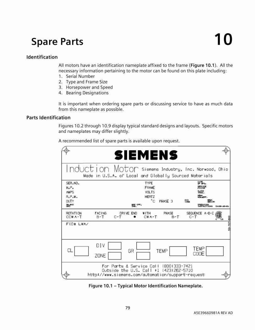
79 A5E39660981A REV AD
10 Spare Parts 10 Identification
All motors have an identification nameplate affixed to the frame (Figure 10.1). All the necessary information pertaining to the motor can be found on this plate including: 1. Serial Number 2. Type and Frame Size 3. Horsepower and Speed 4. Bearing Designations It is important when ordering spare parts or discussing service to have as much data from this nameplate as possible.
Parts Identification
Figures 10.2 through 10.9 display typical standard designs and layouts. Specific motors and nameplates may differ slightly.
A recommended list of spare parts is available upon request.
Figure 10.1 – Typical Motor Identification Nameplate.

80 A5E39660981A REV AD
Figure 10.2 – Only 449 & S449 Typical Motor Identification Nameplate.
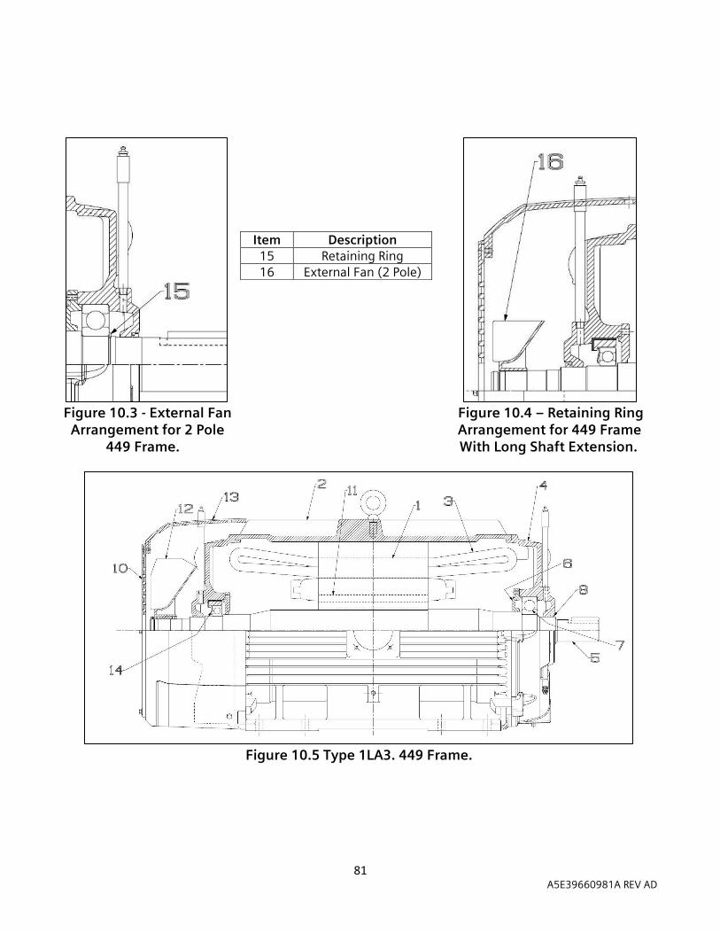
81 A5E39660981A REV AD
Figure 10.3 - External Fan Figure 10.4 – Retaining Ring Arrangement for 2 Pole Arrangement for 449 Frame 449 Frame. With Long Shaft Extension.
Figure 10.5 Type 1LA3. 449 Frame.
Item Description 15 Retaining Ring 16 External Fan (2 Pole)

82 A5E39660981A REV AD
A. Type CZ & 1LA3. 509, 5011 & 5013 Frame.
B. Type CMZ & NCMZ. 509, 5011 & 5013 Frame.
Item Description Item Description 1 Stator Core 12 External Fan (4 pole & slower) 2 Stator Yoke 13 Fan Housing 3 Stator Coils 14 Inboard Seal 4 Bearing Housing 15 Oil Seal
5 Rotor Shaft 16 Bearing Capsule 6 Inner End Cap 17 Sleeve Bearing Bushing 7 Ball Bearing 18 Shims (in bottom half) 8 Shaft Seal 19 Oil Rings
10 Grid Cover 20 Internal Fan
11 Rotor Core 21 Rotor Air Duct (1LA3) Figure 10.6 – Typical 500 Frame, Type CZ, 1LA3, & CMZ/NCMZ Construction.
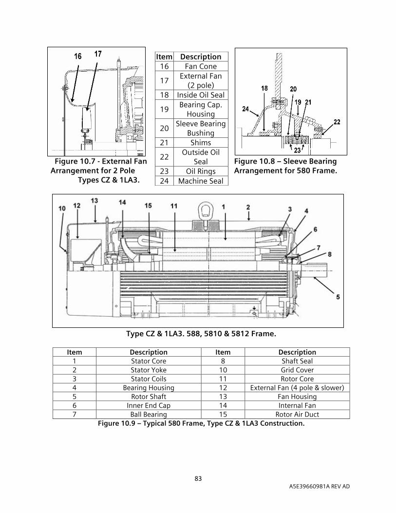
83 A5E39660981A REV AD
Figure 10.7 - External Fan Figure 10.8 – Sleeve Bearing
Arrangement for 2 Pole Arrangement for 580 Frame. Types CZ & 1LA3.
Type CZ & 1LA3. 588, 5810 & 5812 Frame.
Item Description Item Description
1 Stator Core 8 Shaft Seal 2 Stator Yoke 10 Grid Cover 3 Stator Coils 11 Rotor Core 4 Bearing Housing 12 External Fan (4 pole & slower) 5 Rotor Shaft 13 Fan Housing 6 Inner End Cap 14 Internal Fan 7 Ball Bearing 15 Rotor Air Duct
Figure 10.9 – Typical 580 Frame, Type CZ & 1LA3 Construction.
Item Description 16 Fan Cone
17 External Fan
(2 pole) 18 Inside Oil Seal
19 Bearing Cap.
Housing
20 Sleeve Bearing
Bushing 21 Shims
22 Outside Oil
Seal 23 Oil Rings 24 Machine Seal

84 A5E39660981A REV AD
Figure 10.10 – Typical Sleeve Bearing Arrangement for Type CGZ SH400 Frame.
A. Type CGZ & 1LA3. SH400 Frame.
Item Description Item Description
1 Stator Core 8 Shaft Seal 2 Stator Yoke 10 Grid Cover 3 Stator Coils 11 Rotor Core 4 Bearing Housing 12 External Fan (Non-Directional) 5 Rotor Shaft 13 Fan Housing 6 Inner End Cap 14 Internal Fan 7 Ball Bearing 15 Rotor Air Duct
Figure 10.11 – Typical SH400 Frame, Type CGZ & 1LA3 Construction.
Item Description
18 Oil Seal 19 Bearing Capsule
Bushing 20 Sleeve Bearing Bushing 21 Shims 22 Machine Seal 23 Oil Ring

85 A5E39660981A REV AD
Figure 10.12 – Typical Sleeve Bearing Arrangement for Type CGZ 880 & SH450
Frames.
A. Type CGZ. 880 & SH450 Frame.
Item Description Item Description
1 Stator Core 8 Shaft Seal 2 Stator Yoke 10 Grid Cover 3 Stator Coils 11 Rotor Core 4 Bearing Housing 12 External Fan (Directional) 5 Rotor Shaft 13 Fan Housing 6 Inner End Cap 14 Internal Fan 7 Ball Bearing 15 Rotor Air Duct
Figure 10.13 – Typical 880 & SH450 Frame Type CGZ Construction.
Item Description 18 Oil Seal 19 Bearing Capsule
Bushing 20 Sleeve Bearing Bushing 21 Shims 22 Machine Seal
23 Oil Ring

86 A5E39660981A REV AD
Figure 10.14 – Typical Sleeve Bearing Arrangement for Type 1LA4 SH560 Frame.
A. Type 1LA4. SH560 Frame.
Item Description Item Description
1 Stator Core 8 Shaft Seal 2 Stator Yoke 10 Grid Cover 3 Stator Coils 11 Rotor Core 4 Bearing Housing 12 External Fan (Directional) 5 Rotor Shaft 13 Fan Housing 6 Inner End Cap 14 Internal Fan 7 Ball Bearing 15 Rotor Air Duct
Figure 10.15 – Typical SH560 Frame Type 1LA4 Construction.
Item Description 18 Oil Seal 19 Bearing Capsule
Bushing 20 Sleeve Bearing Bushing 21 Shims 22 Machine Seal 23 Oil Ring
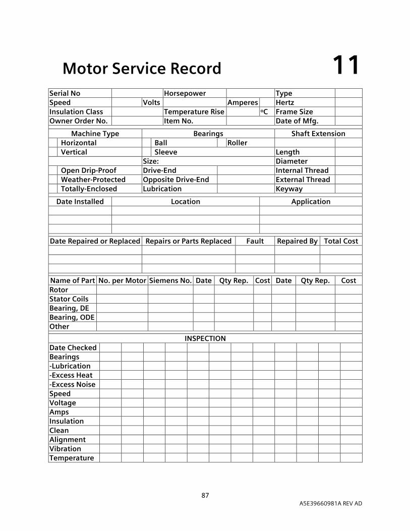
87 A5E39660981A REV AD
11 Motor Service Record 11 Serial No Horsepower Type Speed Volts Amperes Hertz Insulation Class Temperature Rise oC Frame Size Owner Order No. Item No. Date of Mfg.
Machine Type Bearings Shaft Extension Horizontal Ball Roller Vertical Sleeve Length Size: Diameter Open Drip-Proof Drive-End Internal Thread Weather-Protected Opposite Drive-End External Thread Totally-Enclosed Lubrication Keyway
Date Installed Location Application
Date Repaired or Replaced Repairs or Parts Replaced Fault Repaired By Total Cost
Name of Part No. per Motor Siemens No. Date Qty Rep. Cost Date Qty Rep. Cost
Rotor Stator Coils Bearing, DE Bearing, ODE Other
INSPECTION Date Checked Bearings -Lubrication -Excess Heat
-Excess Noise Speed Voltage Amps Insulation Clean Alignment Vibration Temperature
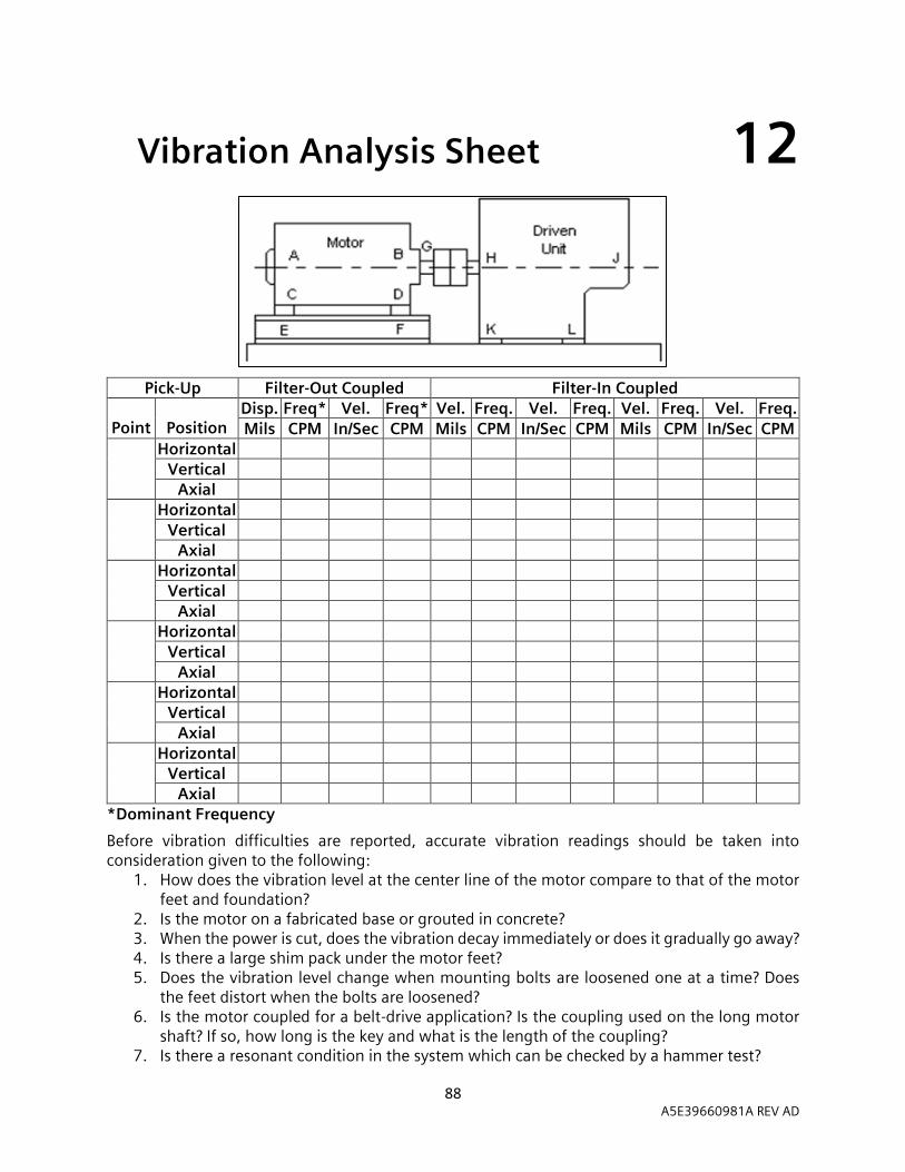
88 A5E39660981A REV AD
12 Vibration Analysis Sheet 12
Pick-Up Filter-Out Coupled Filter-In Coupled
Point
Position Disp. Freq* Vel. Freq* Vel. Freq. Vel. Freq. Vel. Freq. Vel. Freq. Mils CPM In/Sec CPM Mils CPM In/Sec CPM Mils CPM In/Sec CPM
Horizontal Vertical
Axial Horizontal
Vertical Axial
Horizontal Vertical
Axial Horizontal
Vertical Axial
Horizontal Vertical
Axial Horizontal
Vertical Axial
*Dominant Frequency
Before vibration difficulties are reported, accurate vibration readings should be taken into consideration given to the following:
1. How does the vibration level at the center line of the motor compare to that of the motor feet and foundation?
2. Is the motor on a fabricated base or grouted in concrete? 3. When the power is cut, does the vibration decay immediately or does it gradually go away? 4. Is there a large shim pack under the motor feet? 5. Does the vibration level change when mounting bolts are loosened one at a time? Does
the feet distort when the bolts are loosened? 6. Is the motor coupled for a belt-drive application? Is the coupling used on the long motor
shaft? If so, how long is the key and what is the length of the coupling? 7. Is there a resonant condition in the system which can be checked by a hammer test?

89 A5E39660981A REV AD
13 Notes 13 __________________________________________________________________________________________________________________________________________________________________________________________________________________________________________________________________________________________________________________________________________________________________________________________________________________________________________________________________________________________________________________________________________________________________________________________________________________________________________________________________________________________________________________________________________________________________________________________________________________________________________________________________________________________________________________________________________________________________________________________________________________________________________________________________________________________________________________________________________________________________________________________________________________________________________________________________________________________________________________________________________________________________________________________________________________________________________________________________________________________________________________________________________________________________________________________________________________________________________________________________________________________________________________________________________________
90 A5E39660981A REV AD
Siemens Industry, Inc.
Norwood Motor Plant
4620 Forest Avenue
Norwood, OH 45212-3396
(513) 841-3100