induction motors 1pl6 masterdrives - ucc.colorado.eduucc.colorado.edu/siemens/apl6m_1105_en.pdf ·...
TRANSCRIPT

SIMOVERT MASTERDRIVES VC/MC Induction Motors 1PL6 MASTERDRIVES
Siemens Drives & PLCs


Foreword
Motor Description 1
Electrical Connections 2
Technical Data and Motor Characteristics
3
Motor Components 4
Dimension Drawings 5
Appendix A
SIMOVERT MASTERDRIVES VC/MC Induction Motors 1PL6 MASTERDRIVES
Configuration Manual
(APL6M), 11.2005 Edition 6SN1197-0AC67-0BP1
Siemens Drives & PLCs

Safety Guidelines
This manual contains notices you have to observe in order to ensure your personal safety, as well as to prevent damage to property. The notices referring to your personal safety are highlighted in the manual by a safety alert symbol, notices referring only to property damage have no safety alert symbol. These notices shown below are graded according to the degree of danger.
Danger
indicates that death or severe personal injury will result if proper precautions are not taken.
Warning
indicates that death or severe personal injury may result if proper precautions are not taken.
Caution
with a safety alert symbol, indicates that minor personal injury can result if proper precautions are not taken.
Caution
without a safety alert symbol, indicates that property damage can result if proper precautions are not taken.
Notice
indicates that an unintended result or situation can occur if the corresponding information is not taken into account.
If more than one degree of danger is present, the warning notice representing the highest degree of danger will be used. A notice warning of injury to persons with a safety alert symbol may also include a warning relating to property damage.
Qualified Personnel The device/system may only be set up and used in conjunction with this documentation. Commissioning and operation of a device/system may only be performed by qualified personnel. Within the context of the safety notes in this documentation qualified persons are defined as persons who are authorized to commission, ground and label devices, systems and circuits in accordance with established safety practices and standards.
Prescribed Usage Note the following:
Warning
This device may only be used for the applications described in the catalog or the technical description and only in connection with devices or components from other manufacturers which have been approved or recommended by Siemens. Correct, reliable operation of the product requires proper transport, storage, positioning and assembly as well as careful operation and maintenance.
Trademarks All names identified by ® are registered trademarks of the Siemens AG. The remaining trademarks in this publication may be trademarks whose use by third parties for their own purposes could violate the rights of the owner.
Disclaimer of Liability We have reviewed the contents of this publication to ensure consistency with the hardware and software described. Since variance cannot be precluded entirely, we cannot guarantee full consistency. However, the information in this publication is reviewed regularly and any necessary corrections are included in subsequent editions.
Siemens AG Automation and Drives Postfach 48 48 90437 NÜRNBERG GERMANY
Order No.: 6SN1197-0AC67-0BP1 11/2005 Edition
Copyright © Siemens AG 2004-2005 Technical data subject to change

Foreword Information on the documentation
This document is part of the Technical Customer Documentation which has been developed for SIMOVERT MASTERDRIVES VC (Vector Control) and SIMOVERT MASTERDRIVES MC (Motion Control) drive converter systems. All of the documents are available individually. The documentation list, which includes all Advertising Brochures, Catalogs, Overviews, Short Descriptions, Operating Instructions and Technical Descriptions with Order No., ordering address and price can be obtained from your local Siemens office.
This document does not purport to cover all details or variations in equipment, nor to provide for every possible contingency to be met in connection with installation, operation or maintenance.
We would also like to point-out that the contents of this document are neither part of nor modify any prior or existing agreement, commitment or contractual relationship. The sales contract contains the entire obligations of Siemens. The warranty contained in the contract between the parties is the sole warranty of Siemens. Any statements contained herein neither create new warranties nor modify the existing warranty.
Structure of the documentation for 1PH and 1PL motors
Table 1 Configuration Manual, individual documents
Title Order No. (MLFB) Language
Induction Motors, General Section 6SN1197–0AC62–0AP0 German Induction Motors, 1PH2 Motor Section for SIMODRIVE 6SN1197–0AC63–0AP0 German Induction Motors, 1PH4 Motor Section for SIMODRIVE 6SN1197–0AC64–0AP0 German Induction Motors, 1PH7 Motor Section for SIMODRIVE 6SN1197–0AC65–0AP1 German Induction Motors, 1PH7 Motor Section for SIMOVERT MASTERDRIVES VC/MC
6SN1197–0AC66–0AP0 German
Induction Motors, 1PL6 Motor Section for SIMOVERT MASTERDRIVES VC/MC
6SN1197–0AC67–0AP0 German
Induction Motors, 1PH7 Motor Section for SINAMICS, production machines
6SN1197–0AC71–0AP0 German
Induction Motors, 1PH7 Motor Section for SINAMICS, machine tools (processing machines)
6SN1197–0AC72–0AP0 German
Induction Motors 1PL6 MASTERDRIVES Configuration Manual, (APL6M), 11.2005 Edition, 6SN1197-0AC67-0BP1 iii Siemens Drives & PLCs

Foreword
Technical Support If you have any questions, please contact the following Hotline:
Phone: +49 (0) 180 5050–222 Fax: +49 (0) 180 5050–223 Internet: http://www.siemens.com/automation/support-request
Please send any questions about the documentation (e.g. suggestions for improvement, corrections) to the following fax number or email address:
Fax: +49 (0) 9131 98–63315 Fax form: Refer to the correction sheet at the end of the document E-mail: mailto:[email protected]
Information on the products Up-to-date information about our products can be found on the Internet at the following address:
http://www.siemens.com/motioncontrol
Engineering software The PFAD Plus engineering software provides user-friendly engineering support.
Using this program, SIMOVERT MASTERDRIVES Vector Control and Motion Control drive converters can be simply and quickly engineered.
PFAD Plus is a powerful engineering tool that supports the user in all of the engineering steps - from the supply to the motor.
Order No. for the full version of PFAD Plus: 6SW1710-0JA00-2FC0.
Note Not for CAT client systems! You can obtain the CAT client version of PFAD Plus from your system administrator.
Induction Motors 1PL6 MASTERDRIVES iv Configuration Manual, (APL6M), 11.2005 Edition, 6SN1197-0AC67-0BP1

Foreword
Danger and warning information
Danger Commissioning shall not start until it has been absolutely ensured that the machine in which the components described here are to be installed complies with Directive 98/37/EC.
Only appropriately qualified personnel may commission SIMOVERT MASTERDRIVES units and induction motors.
This personnel must carefully observe the technical customer documentation associated with this product and be knowledgeable about and carefully observe the danger and warning information.
Operational electrical equipment and motors have parts and components which are at hazardous voltage levels.
Dangerous mechanical movement may occur in the system during operation.
All work on the electrical system may only be carried-out when the system has been disconnected from the power supply and locked-out so that it cannot be accidently restarted.
SIMOVERT MASTERDRIVES drive units have been designed for operation on low-ohmic grounded line supplies (TN line supplies). For additional information, refer to the appropriate documentation of the drive converter systems.
Warning The successful and safe operation of this equipment and motors depends on correct transport, proper storage and installation, as well as careful operation and maintenance.
The specifications in the Catalogs and quotations also apply to special variants of the devices and motors.
In addition to the danger and warning information/instructions in the technical customer documentation supplied, the applicable domestic, local and plant-specific regulations and requirements must be carefully taken into account.
Caution The motors can have surface temperatures of over +100 °C.
For this reason, temperature-sensitive parts (cables or electronic components, for example) may not be placed on or attached to the motor.
When connecting-up cables, please observe that they – are not damaged – are not subject to tensile stress – cannot be touched by rotating components.
Induction Motors 1PL6 MASTERDRIVES Configuration Manual, (APL6M), 11.2005 Edition, 6SN1197-0AC67-0BP1 v Siemens Drives & PLCs

Foreword
Caution Motors should be connected-up according to the circuit diagram provided. They must not be connected directly to the three-phase supply because this will damage them.
SIMOVERT MASTERDRIVES drive units with induction motors are subject, as part of the routine test, to a voltage test in accordance with EN 50178. While the electrical equipment of industrial machines is being subject to a voltage test in accordance with EN60204-1, Section 19.4, all SIMOVERT MASTERDRIVES drive unit connections must be disconnected/ withdrawn in order to avoid damaging the SIMOVERT MASTERDRIVES drive units.
Note SIMOVERT MASTERDRIVES units with induction motors fulfill, when operational and in dry operating rooms, the Low-Voltage Directive 73/23/EEC.
SIMOVERT MASTERDRIVES units with induction motors fulfill, in the configuration specified in the associated EC Declaration of Conformity, the EMC Directive 89/336/EEC.
Induction Motors 1PL6 MASTERDRIVES vi Configuration Manual, (APL6M), 11.2005 Edition, 6SN1197-0AC67-0BP1

Foreword
ESDS instructions
Caution ElectroStatic Discharge Sensitive Devices (ESDS) are individual components, integrated circuits, or modules that can be damaged by electrostatic fields or discharges.
ESDS regulations for handling boards and equipment:
When handling components that can be destroyed by electrostatic discharge, it must be ensured that personnel, the workstation and packaging are well grounded!
Personnel in ESDS zones with conductive floors may only touch electronic components if they are – grounded through an ESDS bracelet and – wearing ESDS shoes or ESDS shoe grounding strips.
Electronic boards may only be touched when absolutely necessary.
Electronic boards may not be brought into contact with plastics and articles of clothing manufactured from man-made fibers.
Electronic boards may only be placed on conductive surfaces (table with ESDS surface, conductive ESDS foam rubber, ESDS packing bag, ESDS transport containers).
Electronic boards may not be brought close to data terminals, monitors or television sets. Minimum clearance to screens > 10 cm.
Measurements may only be carried-out on electronic boards and modules if – the measuring instrument is grounded (e.g. via a protective conductor) or – before making measurements with a potential-free measuring device, the measuring head is briefly discharged (e.g. by touching an unpainted blank piece of metal on the control cabinet).
Functional requirements The appropriate standards, regulations are directly assigned to the functional requirements.
Induction Motors 1PL6 MASTERDRIVES Configuration Manual, (APL6M), 11.2005 Edition, 6SN1197-0AC67-0BP1 vii Siemens Drives & PLCs

Foreword
Induction Motors 1PL6 MASTERDRIVES viii Configuration Manual, (APL6M), 11.2005 Edition, 6SN1197-0AC67-0BP1

Table of Contents Foreword ...................................................................................................................................................... iii
1 Motor Description ...................................................................................................................................... 1-1
1.1 Characteristics ........................................................................................................................... 1-1
1.2 Technical features...................................................................................................................... 1-3
1.3 Permissible combinations of mechanical versions for SH 225, radial cooling........................... 1-6
1.4 Permissible combinations of mechanical versions for SH 280 .................................................. 1-7
1.5 Selection and ordering data ....................................................................................................... 1-8
1.6 Rating plate data ...................................................................................................................... 1-22
1.7 Cooling ..................................................................................................................................... 1-23
1.8 Bearing design ......................................................................................................................... 1-25 1.8.1 Out-drive types and bearing versions ...................................................................................... 1-25 1.8.2 Bearing lifetime ........................................................................................................................ 1-27 1.8.3 NDE bearings, insulated version (option L27) ......................................................................... 1-30
1.9 Vibration severity – limit values................................................................................................ 1-32
1.10 Mounting .................................................................................................................................. 1-34 1.10.1 Danger and warning information when mounting .................................................................... 1-34 1.10.2 Retaining and mounting instructions........................................................................................ 1-35 1.10.3 Natural frequency when mounted............................................................................................ 1-37
2 Electrical Connections............................................................................................................................... 2-1
2.1 Power connection....................................................................................................................... 2-1
2.2 Connecting-up information......................................................................................................... 2-3
2.3 Connecting-up a separately-driven fan...................................................................................... 2-7
3 Technical Data and Motor Characteristics ................................................................................................ 3-1
3.1 Technical data and characteristics for MASTERDRIVES VC.................................................... 3-2 3.1.1 P/n and M/n diagrams for 3-ph. 400 V AC................................................................................. 3-2 3.1.2 P/n and M/n diagrams for 3-ph. 480 V AC............................................................................... 3-31 3.1.3 P/n and M/n diagrams for 3-ph. 690 V AC............................................................................... 3-60
3.2 Technical data and characteristics for MASTERDRIVES MC ................................................. 3-69 3.2.1 P/n diagrams for 3-ph. 400 V AC............................................................................................. 3-69 3.2.2 P/n diagrams for 3-ph. 480 V AC............................................................................................. 3-89
3.3 Cantilever force/axial force diagrams .................................................................................... 3-109 3.3.1 Cantilever force ...................................................................................................................... 3-109 3.3.2 Axial force .............................................................................................................................. 3-118
Induction Motors 1PL6 MASTERDRIVES Configuration Manual, (APL6M), 11.2005 Edition, 6SN1197-0AC67-0BP1 ix Siemens Drives & PLCs

Table of Contents
4 Motor Components .................................................................................................................................... 4-1
4.1 Thermal motor protection ........................................................................................................... 4-1
4.2 Encoders .................................................................................................................................... 4-3 4.2.1 HTL incremental encoder........................................................................................................... 4-3 4.2.2 Incremental encoder sin/cos 1 Vpp............................................................................................ 4-5 4.2.3 Absolute encoder (EnDat).......................................................................................................... 4-7 4.2.4 2-pole resolver ........................................................................................................................... 4-9
5 Dimension Drawings.................................................................................................................................. 5-1
5.1 Introduction................................................................................................................................. 5-1
5.2 Type of construction IM B3 with separately-driven fan .............................................................. 5-2
5.3 Type of construction IM B3 with second shaft end (SH 280)................................................... 5-35
5.4 Type of construction IM B35 with separately-driven fan .......................................................... 5-41
5.5 Type of construction IM B35 with second shaft end (SH 280)................................................. 5-74
A Appendix....................................................................................................................................................A-1
A.1 References.................................................................................................................................A-1
Index ................................................................................................................................................... Index-1
Induction Motors 1PL6 MASTERDRIVES x Configuration Manual, (APL6M), 11.2005 Edition, 6SN1197-0AC67-0BP1

Motor Description 1 1.1 1.1 Characteristics
Overview 1PL6 motors are compact, force-ventilated and also enclosed-ventilated squirrel-cage asynchronous motors with degree of protection IP23. The motors are ventilated, as standard, using a mounted separately-driven fan unit.
The motor can be ordered either with the air flow from the motor drive shaft end (DE) to the motor non-drive shaft end (NDE) - or vice versa.
The motors were specifically developed for operation with SIMOVERT MASTERDRIVES Vector Control and Motion Control drive systems. Depending on the control requirements, the appropriate encoder systems are available for the motors. These encoders are used to sense the motor speed and indirect position.
Figure 1-1 1PL6 motors
The motors comply with DIN standards and have degree of protection IP23 in accordance with EN 60034-5 (or IEC 60034-5). With this degree of protection, the motors are not suitable for operation in aggressive atmospheres or for installation outdoors.
DIN EN 60721-3-4 or IEC 721-3-4 Standards can be applied to classify ambient conditions for aggressive environments or mounting outdoors. The environmental effects and their limit values are defined in various Classes in this standard.
Generally, 1PL6 motors can be defined for environmental effects with Quality Class IE41; whereby the following effects must be especially taken into account::
Induction Motors 1PL6 MASTERDRIVES Configuration Manual, (APL6M), 11.2005 Edition, 6SN1197-0AC67-0BP1 1-1 Siemens Drives & PLCs

Motor Description 1.1 Characteristics
• 4K2 (climatic ambient conditions)
• 4C2 (chemically active substances/materials)
• 4S2 (mechanically active substances/materials)
Benefits • Extremely high power density with compact dimensions (50 to 60% higher output as
compared to 1PH7 in degree of protection IP55)
• Speeds to zero without reduction of the torque
• Robustness
• Essentially maintenance-free
• High cantilever force loading
• High smooth running characteristics, even at the lowest speeds
• Integrated encoder system to sense the motor speed, connected using a connector
• Terminal box for power line connection
• Motor temperature monitoring with KTY 84
• Variable cooling versions
• Basic external cooling using a pipe connection
• Optional bearing designs with re-lubrication device and insulated bearings (NDE)
Applications Mounted in dry indoor areas (no aggressive atmosphere).
Crane systems:
• Hoisting gears and closing gears for cranes
Printing industry:
• Main drives for printing machines
Manufacture of rubber, plastic and wire:
• Drives for extruders, calenders, rubber injection machines, foil machines, assembly units, fleece plants
• Wire-drawing machines, cable stranding machines, etc.
General applications such as coiler and winder drives.
Induction Motors 1PL6 MASTERDRIVES 1-2 Configuration Manual, (APL6M), 11.2005 Edition, 6SN1197-0AC67-0BP1

Motor Description 1.2 Technical features
1.2 1.2 Technical features Table 1-1 Design features
Technical features Version Type of motor Induction motor Type of construction
60034–7) IM B3, refer to Options and Chapter "Permissible combinations of mechanical designs"
Degree of protection 60034–5)
IP23 Shaft heights 180 and 225:
R; refer to options Vibration severity grade 60034–14)
SH 280: N; refer to Chapter "Permissible combinations of mechanical versions" and "Selection and ordering data"
Shaft and flange accuracy, concentricity and axial eccentricity
60072–1)
Tolerance stage N; refer to "Selection and ordering data"
Shaft end 748–3; IEC 60072–1)
with key, half key balancing; issible combinations of mechanical versions" and
"Selection and ordering data" Shaft heights 180 and 225:
Forced-ventilation and open-circuit cooling
air flow direction from NDE to DE SH 225 and SH 280: Forced ventilation, the fan is radially mounted
at the NDE, air flow direction from NDE to DE
Cooling (acc. to EN 60034–6; IEC 60034–6)
refer to the options, Chapter "Permissible combinations of mechanical versions" and "Selection and ordering data"
Winding insulation 60034–1)
Temperature class F for a coolant temperature up to 40 °C
Thermal motor protection (acc. to EN 60034-11, IEC 60034–11)
KTY 84 temperature sensor in the stator winding for SH 280: Additional KTY 84 as reserve SH 180 to 280: 3-ph. 400 V AC Motor voltage
SH 280: refer to options and Chapter "Selection and ordering data"
Motor noise (acc. to DIN 45635, Part 10) Tolerance + 3 dB Air flow direction from NDE to DE
SH 180:
SH 280:
73 dB(A) to n = 2000 RPM 74 dB(A) to n = 2000 RPM 74 dB(A) to n= 2000 RPM
Vibration stressing (acc. to IEC 68-2-6)
3 g axial and 6 g radial (higher vibration resistance on request)
Connection type Motors and fans: Encoders:
via terminal box via connector (mating connector is not included in the scope of supply)
SH 180 and 225: top-mounted, cable entry from the right SH 225: righthand side (NDE), cable entry DE, encoder connector
at the top SH 280: righthand side (NDE), cable entry below, encoder
connector at the DE
Terminal box arrangement
refer to the options, Chapter "Permissible combinations of mechanical versions" and "Selection and ordering data"
(acc. to EN 60034–7; IEC
(acc. to EN 60034–5; IEC
(acc. to EN 60034–14, IEC
(acc. to DIN 42955, IEC
(acc. to DIN refer to options, Chapter "Perm
axial fan on the NDE,
(acc. to EN 60034-1, IEC
3-ph. 480 V AC
SH 225:
Induction Motors 1PL6 MASTERDRIVES Configuration Manual, (APL6M), 11.2005 Edition, 6SN1197-0AC67-0BP1 1-3 Siemens Drives & PLCs

Motor Description 1.2 Technical features
Technical features Version
Speed encoder Refer to options and Chapter "Selection and ordering data" Balancing (acc. to IEC 60034-14) Standard: Half-key balancing (dynamic), Code: H on the shaft face Bearing version DE (Standard) For coupling out-drive: Deep-groove ball bearings
For belt out-drive or increased cantilever forces: Cylindrical roller bearings Bearing design, non-drive end Locating bearing: Deep-groove ball bearings
Option, insulated design, refer to the following table Installation height above sea level ≦ 1000 m above sea level, otherwise power de-rating
(refer to Chapter "Cooling") Paint finish with primer,
refer to options, Chapter "Permissible combinations of mechanical versions" and "Selection and ordering data"
Documentation supplied with the motors
Operating Instructions
(acc. to EN 60034-1, IEC 60034-1)
Induction Motors 1PL6 MASTERDRIVES 1-4 Configuration Manual, (APL6M), 11.2005 Edition, 6SN1197-0AC67-0BP1

Motor Description 1.2 Technical features
Options
Table 1-2 Options
Order code
Option description For use with 1PL6 induction motors in the appropriate version
SH 180 SH 225 Axial cooling
SH 225 Radial ventilation
SH 280
R1Y Normal paint finish in another color, RAL ...(plain text description required)
R2Y Special paint finish in another color, RAL ...(plain text description required)
C30 Winding version 690 V _ _ G14 Fan unit with air filter ⃝ G 00 Separately-driven fan, radial NDE left _ s. Tab. 1-4 G 02 Separately-driven fan, radial NDE right _ s. Tab. 1-4 G 04 Separately-driven fan, radial NDE top _ s. Tab. 1-4 G80 POG10 pulse encoder, mounting prepared _ K08 Encoder connector mounted opposite _ K09 Terminal box arrangement, NDE right _ s. Tab. 1-4 K10 Terminal box arrangement, NDE left _ s. Tab. 1-4 K 11 Terminal box arrangement, NDE top _ s. Tab. 1-4 K16 Second standard shaft end (only possible without encoder) _ ⃝ K31 2. Rating plate supplied separately in terminal box K40 Re-lubrication devices, DE and NDE Standard K45 230 V anti-condensation heating _ ⃝ K55 Cable entry plate, terminal box, customer-specific (plain text is
required)
K83 The terminal box is rotated through +90 degrees (basis is the standard)
_
K84 The terminal box is rotated through –90 degrees (basis is the standard)
_
K85 The terminal box is rotated through +180 degrees (basis is the standard)
_
L27 NDE bearing, insulated version Standard M83 Additional thread for a setting screw at the motor feet _ _ Y55 Non-standard shaft end DE ⃝ ⃝ ⃝ Y80 Different rating plate data (plain text is required) ⃝ ⃝ ⃝ Y82 Supplementary plate with the orderer's data ⃝ ⃝ ⃝
Option possible ⃝ On request – Not available
Induction Motors 1PL6 MASTERDRIVES Configuration Manual, (APL6M), 11.2005 Edition, 6SN1197-0AC67-0BP1 1-5 Siemens Drives & PLCs

Motor Description 1.3 Permissible combinations of mechanical versions for SH 225, radial cooling
1.3 1.3 Permissible combinations of mechanical versions for SH 225, radial cooling
Table 1-3 Matrix for options and assignments for SH 225
Induction Motors 1PL6 MASTERDRIVES 1-6 Configuration Manual, (APL6M), 11.2005 Edition, 6SN1197-0AC67-0BP1

Motor Description 1.4 Permissible combinations of mechanical versions for SH 280
1.4 1.4 Permissible combinations of mechanical versions for SH 280
Table 1-4 Matrix for options and assignments for SH 280
Induction Motors 1PL6 MASTERDRIVES Configuration Manual, (APL6M), 11.2005 Edition, 6SN1197-0AC67-0BP1 1-7 Siemens Drives & PLCs

Motor Description 1.5 Selection and ordering data
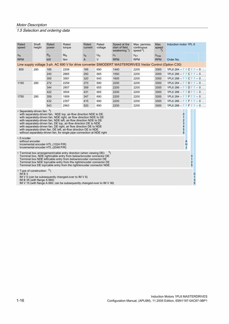
1.5 1.5 Selection and ordering data
Induction Motors 1PL6 MASTERDRIVES 1-8 Configuration Manual, (APL6M), 11.2005 Edition, 6SN1197-0AC67-0BP1

Motor Description 1.5 Selection and ordering data
1) n1: Max. permissible speed at constant power or speed where for P=PN, there is still a 30% power reserve up to the
stall limit. 2) nS1: Max. permissible speed that is continuously permitted without speed duty cycles. 3) nmax: Maximum speed. It is not permissible that this speed is exceeded! Notice: The maximum speed is limited to
lower values due to fmax < 5∙ fN. 4) The speed is reduced for increased cantilever forces. 5) Preferred air-flow direction in polluted environment. 6) Number "5" for SH 225 radial cooling, refer to Table 1-3.
Induction Motors 1PL6 MASTERDRIVES Configuration Manual, (APL6M), 11.2005 Edition, 6SN1197-0AC67-0BP1 1-9 Siemens Drives & PLCs

Motor Description 1.5 Selection and ordering data
Induction Motors 1PL6 MASTERDRIVES 1-10 Configuration Manual, (APL6M), 11.2005 Edition, 6SN1197-0AC67-0BP1

Motor Description 1.5 Selection and ordering data
1) n1: Max. permissible speed at constant power or speed where for P=PN, there is still a 30% power reserve up to the
stall limit. 2) nS1: Max. permissible speed that is continuously permitted without speed duty cycles. 3) nmax: Maximum speed. It is not permissible that this speed is exceeded! Notice: The maximum speed is limited to
lower values due to fmax < 5∙ fN. 4) Possible combination, refer to "Permissible combinations of mechanical versions".
Induction Motors 1PL6 MASTERDRIVES Configuration Manual, (APL6M), 11.2005 Edition, 6SN1197-0AC67-0BP1 1-11 Siemens Drives & PLCs

Motor Description 1.5 Selection and ordering data
Induction Motors 1PL6 MASTERDRIVES 1-12 Configuration Manual, (APL6M), 11.2005 Edition, 6SN1197-0AC67-0BP1

Motor Description 1.5 Selection and ordering data
1) n1: Max. permissible speed at constant power or speed where for P=PN, there is still a 30% power reserve up to the
stall limit. 2) nS1: Max. permissible speed that is continuously permitted without speed duty cycles. 3) nmax: Maximum speed. It is not permissible that this speed is exceeded! Notice: The maximum speed is limited to
lower values due to fmax < 5∙ fN. 4) The speed is reduced for increased cantilever forces. 5) Preferred air-flow direction in polluted environment. 6) Number "5" for SH 225 radial cooling, refer to Table 1-3
Induction Motors 1PL6 MASTERDRIVES Configuration Manual, (APL6M), 11.2005 Edition, 6SN1197-0AC67-0BP1 1-13 Siemens Drives & PLCs

Motor Description 1.5 Selection and ordering data
Induction Motors 1PL6 MASTERDRIVES 1-14 Configuration Manual, (APL6M), 11.2005 Edition, 6SN1197-0AC67-0BP1

Motor Description 1.5 Selection and ordering data
1) n1: Max. permissible speed at constant power or speed where for P=PN, there is still a 30% power reserve up to the
stall limit. 2) nS1: Max. permissible speed that is continuously permitted without speed duty cycles. 3) nmax: Maximum speed. It is not permissible that this speed is exceeded! Notice: The maximum speed is limited to
lower values due to fmax < 5∙ fN. 4) Possible combination, refer to "Permissible combinations of mechanical versions".
Induction Motors 1PL6 MASTERDRIVES Configuration Manual, (APL6M), 11.2005 Edition, 6SN1197-0AC67-0BP1 1-15 Siemens Drives & PLCs
Motor Description 1.5 Selection and ordering data
Induction Motors 1PL6 MASTERDRIVES 1-16 Configuration Manual, (APL6M), 11.2005 Edition, 6SN1197-0AC67-0BP1

Motor Description 1.5 Selection and ordering data
1) n1: Max. permissible speed at constant power or speed where for P=PN, there is still a 30% power reserve up to the
stall limit. 2) nS1: Max. permissible speed that is continuously permitted without speed duty cycles. 3) nmax: Maximum speed. It is not permissible that this speed is exceeded! Notice: The maximum speed is limited to
lower values due to fmax < 5∙ fN. 4) Notice: The rated converter current is less than the rated motor current. 5) Possible combination, refer to "Permissible combinations of mechanical versions".
Induction Motors 1PL6 MASTERDRIVES Configuration Manual, (APL6M), 11.2005 Edition, 6SN1197-0AC67-0BP1 1-17 Siemens Drives & PLCs

Motor Description 1.5 Selection and ordering data
7 7 7 7
7 7 7 7
7 7 7 7
7 7 7 7
7 7 7 7
7 7 7 7
7 7 7 7
7 7 7 7
7 7 7 7
7 7 7 7
7 7 7 7
7 7 7 7
7 7 7 7
7 7 7 7
7 7 7 7
7 7 7 7
7 7 7 7
7 7 7 7
7 7 7 7
7 7 7 7
Induction Motors 1PL6 MASTERDRIVES 1-18 Configuration Manual, (APL6M), 11.2005 Edition, 6SN1197-0AC67-0BP1

Motor Description 1.5 Selection and ordering data
1) n1: Max. permissible speed at constant power or speed where for P=PN, there is still a 30% power reserve up to the
stall limit. 2) nS1: Max. permissible speed that is continuously permitted without speed duty cycles. 3) nmax: Maximum speed. It is not permissible that this speed is exceeded! Notice: The maximum speed is limited to
lower values due to fmax < 2∙ fN. 4) The speed is reduced for increased cantilever forces. 5) Notice: The rated converter current is less than the rated motor current 6) Preferred air-flow direction in polluted environment 7) Number "5" for SH 225 radial cooling, refer to Table 1-3.
Induction Motors 1PL6 MASTERDRIVES Configuration Manual, (APL6M), 11.2005 Edition, 6SN1197-0AC67-0BP1 1-19 Siemens Drives & PLCs

Motor Description 1.5 Selection and ordering data
Induction Motors 1PL6 MASTERDRIVES 1-20 Configuration Manual, (APL6M), 11.2005 Edition, 6SN1197-0AC67-0BP1

Motor Description 1.5 Selection and ordering data
1) n1: Max. permissible speed at constant power or speed where for P=PN, there is still a 30% power reserve up to the
stall limit. 2) nS1: Max. permissible speed that is continuously permitted without speed duty cycles. 3) nmax: Maximum speed. It is not permissible that this speed is exceeded! Notice: The maximum speed is limited to
lower values due to fmax < 2∙ fN. 4) The speed is reduced for increased cantilever forces. 5) Notice: The rated converter current is less than the rated motor current 6) Preferred air-flow direction in polluted environment 7) Number "5" for SH 225 radial cooling, refer to Table 1-3
Induction Motors 1PL6 MASTERDRIVES Configuration Manual, (APL6M), 11.2005 Edition, 6SN1197-0AC67-0BP1 1-21 Siemens Drives & PLCs

Motor Description 1.6 Rating plate data
1.6 1.6 Rating plate data
3 X Mot. 1PL6 286-0HD000AA0 No N- 1119762010001 / 2002
IM B3 IP 23 Th.Cl. F
V A kW cosϕ Hz RPM
MADE IN GERMANY
Gew./WT. 1475 kg
380 637 355 0.89 39 1150445 637 410 0.89 45.5 1350
EN/EC 60034-1 max 3300 RPM
KTY84ENCODER_H01_1024_SR
13
1
2 3
4 5 6
7
8
9
1011
1214
15
Figure 1-2 Rating plate (example for 1PL6286)
Table 1-5 Description of the rating plate data
Position Description/Technical data
1 Motor type: Induction motor 2 Design 3 Degree of protection 4 Rated voltage [V] and winding circuit 5 Rated current [A] 6 Rated power [kW] 7 Standards and specifications 8 Code, encoder type, temperature sensor 9 Ident. No., production number 10 Motor weight [kg] 11 Temperature class 12 Rated speed [RPM] 13 Rated frequency [Hz] 14 Power factor [cosφ] 15 Maximum speed [RPM]
Induction Motors 1PL6 MASTERDRIVES 1-22 Configuration Manual, (APL6M), 11.2005 Edition, 6SN1197-0AC67-0BP1

Motor Description 1.7 Cooling
1.7 1.7 Cooling
Description 1PL6 motors are force ventilated and open-circuit air-cooled low-voltage squirrel-case induction motors and have as standard a mounted separately-driven fan unit. They have an enclosed design with inner cooling circuit (IC06 cooling type according to DIN EN/IEC 60034–6).
Ambient/cooling medium temperature Operation: T = -15 °C to +40 °C (without any restrictions) Storage: T = -20 °C to +70 °C
All of the Catalog data refer to an ambient temperature of 40 °C, mounted so that the motors are not thermally insulated and an installation altitude up to 1000 m above sea level.
If other conditions prevail (ambient temperature > 40 °C or installation altitude > 1000 m above sea level), the permissible torque/power must be defined using the factors from the following table (torque/power reduction according to EN 60034-6).
Ambient temperatures and installation altitudes are rounded-off to 5 °C or 500 m respectively.
Table 1-6 Factors to reduce the torque/power (de-rating)
Ambient temperature in °C Installation altitude above sea level 40 45 50
1000 1.00 0.96 0.92 1500 0.97 0.93 0.89 2000 0.94 0.90 0.86 2500 0.90 0.86 0.83 3000 0.86 0.82 0.79 3500 0.82 0.79 0.75 4000 0.77 0.74 0.71
Caution The surface of the motors can reach temperatures of over 100° C.
Induction Motors 1PL6 MASTERDRIVES Configuration Manual, (APL6M), 11.2005 Edition, 6SN1197-0AC67-0BP1 1-23 Siemens Drives & PLCs

Motor Description 1.7 Cooling
Fan mounting SH 180 and SH 225:
an be rotated through 4 x 90°. The fan is axially mounted on the NDE and c
SH 225 and SH 280: far as the mounting type is concerned, can be
differently ordered. The fan is radially mounted at the NDE and as
The minimum clearance to the customer's mounted parts and components and the air discharge opening as well as the minimum clearance S between the air intake and air discharge openings and adjacent components must be observed and maintained.
Table 1-7 Minimum clearances
Shaft height Clearance to the customer's mounted parts and components
[mm]
Clearance S [mm]
180 150 100
225 150 100
280 170 120
[mm]
Cooling conditions for motors with pipe connection For 1PL6 motors that have been designed for pipe cooling and/or separately-driven fan operation, the appropriately dimensioned pipes/ducts and fans must be suitably mounted and connected-up.
For motors with pipe/duct connection, the potential pressure drop within the motor is specified in the Table "Air flow rate, air flow direction and air discharge".
Air flow rate, air flow direction and air discharge
Table 1-8 Air flow rate, air flow direction and air discharge
Shaft height Air flow direction Required
[m3/s]
Air discharge Pressure drop (Δp) [Pa]
NDE - DE radial 1) 180
DE - NDE
0.27
radial 1)
650
NDE - DE radial 225 DE - NDE
0.38 radial 1)
850
NDE - DE radial 280 DE - NDE
0.52 radial
600
[mm] air flow rate
1) Fan can be rotated through 4 x 90°
Induction Motors 1PL6 MASTERDRIVES 1-24 Configuration Manual, (APL6M), 11.2005 Edition, 6SN1197-0AC67-0BP1

Motor Description 1.8 Bearing design
For air-cooled motors, the cooling ducts, through which the ambient air flows, should be regularly cleaned depending on the degree of pollution at the mounting location. These air ducts can be cleaned, e.g. using dry, oil-free compressed air. Please refer to the Operating Instructions for details.
1.8 1.8 Bearing design
1.8.1 Out-drive types and bearing versions The 1PL6 induction motors have roller bearings with grease lubrication. A deep-groove ball bearing is used as locating bearing at the NDE.
Depending on the load type, a deep-groove ball bearing or cylindrical roller bearing is used as floating bearing at the DE.
Spring elements are integrated in the bearing insert at the DE in order to compensate for the axial play of the outer bearing rings.
Table 1-9 Out-drive type with the appropriate bearing design
Application Bearing arrangement
Coupling out-drive SH 180 to 280
Belt out-drive with normal cantilever force Belt out-drive with increased cantilever force Note: For a belt out-drive, a minimum cantilever force is required, refer to Chapter .
SH 180 to 280
(1) = Deep-groove ball bearings (2) = Cylindrical roller bearings
Induction Motors 1PL6 MASTERDRIVES Configuration Manual, (APL6M), 11.2005 Edition, 6SN1197-0AC67-0BP1 1-25 Siemens Drives & PLCs

Motor Description 1.8 Bearing design
Bearing version, drive type and maximum speed
Table 1-10 Bearing version, drive type and maximum speeds
Frame size/ motor type
Bearing type/ drive type
Bearing type motor side
Bearing designation
Max. continuous speed
in S1 duty [RPM]
Max. speed
[RPM]
Max. perm. cantilever force
[N] ns1 nmax FGmax 180 Deep-groove ball bearing
for coupling out-drive DE NDE
6214 C3 6214 C3
3500 5000 4900
180 Cylindrical roller bearings for belt out-drive
DE NDE
NU2214E 3500 5000 12800
180 Cylindrical roller bearings for increased cantilever forces
DE NDE
NU2214E 3000 5000 16500
225 Deep-groove ball bearing for coupling out-drive
DE NDE
6216 C3 6216 C3
3100 4500 5200
225 Cylindrical roller bearings for belt out-drive
DE NDE
NU2216E 3100 4500 15000
224 226
Cylindrical roller bearings for increased cantilever forces
DE NDE
NU2216E 2700 4500 20000
228 Cylindrical roller bearings for increased cantilever forces
DE NDE
NU2216E 2500 4000 20000
280 Deep-groove ball bearing for coupling out-drive
DE NDE
6220 C3 6220 C3
2200 3300 approx. 8700
280 Cylindrical roller bearings for belt out-drive
DE NDE
NU220E 2200 3300 approx. 26700
limit1) 2)
6214 C3
6214 C3
6216 C3
6216 C3
6216 C3
6220 C3
1) For continuous operation (with 30 % nmax, 60 % 2/3 nmax, 10 % standstill) for a duty cycle duration of 10 min. 2) Max. permissible cantilever forces for X=50 mm shaft end length and n=1000 RPM; for additional values, refer to
Chapter "Cantilever force/axial force diagrams"
Note If the motor is operated at speeds between ns1 and nmax, a speed duty cycle with low speeds and standstill intervals is required in order to reliably guarantee that the grease is well-distributed in the bearings.
Continuous speed nS1 The max. permissible continuous operating speed nS1 depends on the bearings and the shaft height.
Induction Motors 1PL6 MASTERDRIVES 1-26 Configuration Manual, (APL6M), 11.2005 Edition, 6SN1197-0AC67-0BP1

Motor Description 1.8 Bearing design
1.8.2 Bearing lifetime The bearing lifetime is limited by material fatigue (fatigue lifetime) or if the lubrication fails (grease lifetime). The fatigue lifetime (statistical bearing lifetime L10h) is mainly dependent on the mechanical load. The inter-dependency is shown in the cantilever force/axial force diagrams. The values are determined according to DIN/ISO 281.
The grease lifetime is mainly dependent on the bearing size, speed, temperature as well as the vibrational load.
The grease lifetime can be extended by especially favorable operating conditions (low average speed, low bearing temperatures, cantilever force or vibration load).
A reduction can be expected for difficult operating conditions and when motors are mounted vertically.
Lifetime lubrication (without re-lubricating) For lifetime lubrication, the grease lifetime is harmonized with the bearing lifetime L10h.
Bearing change interval (tLW) The recommended bearing change intervals (refer to the following tables) are obtained from the inter-dependencies mentioned above for a specific operating point such as:
• Coupling or belt out-drive
• Horizontal mounting
• Cooling-medium temperature up to max. +40 °C
• Complying with the permissible cantilever and axial forces (refer to Chapter "Cantilever and axial forces")
• Complying with the maximum permissible speeds (refer to Chapter "Technical data and characteristics")
Induction Motors 1PL6 MASTERDRIVES Configuration Manual, (APL6M), 11.2005 Edition, 6SN1197-0AC67-0BP1 1-27 Siemens Drives & PLCs

Motor Description 1.8 Bearing design
Table 1-11 Recommended bearing change intervals (standard bearing design)
Recommended bearing change interval tLw [h]
Frame size
Out-drive type Average operating speed
RPM]
Stat. bearing 10h [h]
Permanent lubrication Re-lubrication Coupling out-drive ≤ 2000 40000 20000 40000
Belt out-drive 24000 24000
180
Increased cantilever forces
≤ 1500 20000
12000 20000
Coupling out-drive ≤ 1750 40000 1) 20000 40000 1) Belt out-drive 24000 24000
225
Increased cantilever forces
≤ 1400 20000
12000 20000
Coupling out-drive ≤ 1500 40000 2) 20000 40000 2) 280 Belt out-drive 3) ≤ 1300 24000 12000 24000
lifetime L
1) when vertically mounted 25000 [h] 2) when vertically mounted 24000 [h] 3) vertical mounting not permissible
Re-lubrication For motors which can be re-lubricated at defined re-lubricating intervals, the bearing lifetime can be extended and/or unfavorable factors such as mounting conditions, speed, bearing size and mechanical load can be compensated (refer to the table "Recommended bearing change intervals (standard bearing design)").
Depending on the frame size, restrictions have to be taken into account - e.g. vertical mounting/shaft position.
For shaft height 280, it is possible to re-lubricate the bearings through a lubricating nipple.
It is possible to re-lubricate motors, shaft heights 180 and 225. A lubricating nipple is optionally provided, Code K40.
Re-lubricating intervals The re-lubricating intervals are specified on the lubricant plate of the induction motor (technical data, refer to Table "Re-lubricating intervals").
Note If there are longer periods of time (e.g. greater than 1 re-lubrication interval) between the motor being supplied and commissioned, then the bearings must be lubricated. When re-lubricating, the shaft must be rotated in order to distribute the grease in the bearing (additional information and instruction, refer to the Operating Instructions).
Induction Motors 1PL6 MASTERDRIVES 1-28 Configuration Manual, (APL6M), 11.2005 Edition, 6SN1197-0AC67-0BP1

Motor Description 1.8 Bearing design
Table 1-12 Re-lubricating intervals
Frame size
Bearing type/ drive type
Bearingtype
motor side
Bearing designa-
tion
Re-lubricating intervals in operating
hours
[h]
Quantity of grease for each
re-lubrication
[g]
Grease
2)
[g]
Possible
re-lubricating
180 Deep-groove ball bearings coupling out-drive
DE NDE
6214 C3 6214 C3
8000 15 80 5
180 Cylindrical roller bearings belt out-drive, increased cantilever forces
DE NDE
NU2214E 6000 20 80 4
225 Deep-groove ball bearings coupling out-drive
DE NDE
6216 C3 6216 C3
8000 25 160 6
225 Cylindrical roller bearings belt out-drive, increased cantilever forces
DE NDE
NU2216E 6000 40 160 4
280 Deep-groove ball bearings coupling out-drive
DE NDE
6220 C3 6220 C3
4000 40 400 10
280 Cylindrical roller bearings belt out-drive, increased cantilever forces
DE NDE
NU220E 3000 40 400 10
chamber number of
operation 1) intervals 3)
6214 C3
6216 C3
6220 C3
1) Grease quantity for re-lubrication, normal conditions: - cooling-medium temperature up to max. +40 °C - horizontal mounting - average operating speed, refer to the table "Recommended bearing change intervals (standard bearing design)" - complying with the permissible cantilever and axial forces (refer to Chapter "Cantilever and axial forces") - complying with the max. permissible speeds (refer to the characteristics) 2) Quantity of grease that can be injected into the grease chamber when precisely maintaining the quantity of grease
for each re-lubrication interval. 3) Calculation number of re-lubricating intervals; the bearing lifetime is specified (refer to Chapter "Bearing lifetime)
according to statistical perspectives in accordance with the L10h definition.
Note Unfavorable factors such as the effects of mounting/installation, speed or mechanical loads require that the re-lubricating intervals are appropriately adapted.
Situations such as these require special consideration or must be be calculated - and must be engineered according to the limitations and constraints together with the responsible motors plant.
Induction Motors 1PL6 MASTERDRIVES Configuration Manual, (APL6M), 11.2005 Edition, 6SN1197-0AC67-0BP1 1-29 Siemens Drives & PLCs

Motor Description 1.8 Bearing design
1.8.3 NDE bearings, insulated version (option L27)
Relevant, additional bearing currents When compared to a pure sinusoidal supply, the pulsed output voltage of a frequency converter results in additional motor bearing currents. The relevant additional bearing currents are:
• Circulating currents
• EDM currents
• Rotor ground currents
Factors that influence bearing currents Above a certain magnitude, bearing currents result in localized melting at the bearing rings and rolling assemblies as well as lubricant wear. This reduces the bearing lifetime. Essential influencing factors include:
• Motor speed and associated operating time
• Pulse frequency of the frequency converter
• Grounding relationships between the motor and the connected load
Application for option L27 At speeds < 500 RPM, the load due to bearing currents increases significantly. Option L27 is required if the motor is operated in the speed range between 0 ... 500 RPM for a longer period of time. Without option L27, the total operating time in the speed range 0 ... 500 RPM may be a maximum of 800 h (for an assumed bearing change interval (tLW) of the bearings of 20,000 h.
The table below is applicable for motors connected to SIMOVERT MASTERDRIVES drive converters and inverters in a closed-loop control version:
• Vector Control (VC) with pulse frequencies of 2.5 kHz and 6 kHz
• Motion Control (MC) with pulse frequencies of 5 kHz and 10 kHz
Table 1-13 Measures that are required for operation in the speed range < 500 RPM
Shaft height Bearing change interval (tLW) for permanent lubrication [h] 1)
Options that are required
Comments
SH 180 L27 Insulated NDE bearings
SH 225 L27 Insulated NDE bearings
SH 280
20000
_ Generally insulated NDE bearings
1) Definition, refer to the table "Recommended bearing change intervals (standard bearing design)"
Induction Motors 1PL6 MASTERDRIVES 1-30 Configuration Manual, (APL6M), 11.2005 Edition, 6SN1197-0AC67-0BP1

Motor Description 1.8 Bearing design
Motor grounding In order to avoid rotor ground currents, the motor frame should be well grounded - e.g. by using shielded motor cables. The motor cable shield should be connected at both ends through the largest possible surface area.
For specific applications, the grounding of the motor Zhg can be more unfavorable than the grounding of the connected loads Zrg, e.g. for long motor cables and when the motor is mounted in an insulated fashion. In this case, the capacitive discharge (leakage) current of the motor flows from the motor frame through the motor shaft to the connected load and from there to ground.
Figure 1-3 Bearing current due to the grounding situation (=rotor ground current)
The rotor ground current should be avoided by using an electrically insulating coupling. If such a coupling cannot be used for mechanical reasons, then the motor frame must be connected to the load through the largest possible surface area. The capacitive discharge (leakage) current then flows from the motor frame to the load and not through the bearings. The connection between the motor frame and load is only effective if it represents an extremely low impedance for the high-frequency discharge (leakage) current. To achieve this, use several flat straps, e.g. grounding straps, metal plates.
Figure 1-4 Connection between the motor frame and load to avoid rotor ground currents
Induction Motors 1PL6 MASTERDRIVES Configuration Manual, (APL6M), 11.2005 Edition, 6SN1197-0AC67-0BP1 1-31 Siemens Drives & PLCs

Motor Description 1.9 Vibration severity – limit values
1.9 1.9 Vibration severity – limit values The diagrams are included in the Configuration Manual, "General Part for Induction Motors".
Foot support
Note A foot support is required for the following motors in order to maintain the vibration severity limit values:
SH 180 to SH 280 for type of construction IM B35.
For SH 180 to SH 280, a foot support can be eliminated by appropriately engineering the motor - refer to the engineering information and instructions in the Chapter "Mounting".
Permissible vibrations
Note In order to ensure perfect functioning and a long lifetime, the vibration values specified according to ISO 10816 should not be exceeded at the motor.
Table 1-14 Permissible vibration values
Vibrational velocity Vrms [mm/s]
Vibrational frequency f [Hz]
Vibrational acceleration
10 0.4 4.5 250 10
a [m/s2]
Note Deviating from this standard, motors may be loaded as following with restrictions regarding the lifetime and operated outside the natural mounting frequency:
Induction Motors 1PL6 MASTERDRIVES 1-32 Configuration Manual, (APL6M), 11.2005 Edition, 6SN1197-0AC67-0BP1
Motor Description 1.9 Vibration severity – limit values
Table 1-15 Vibrational values where the lifetime is restricted
Axial Radial
0.1 g 1 g
Note The mounted parts and components (belt pulley, coupling components etc.) must be balanced according to ISO 1949. Balancing quality G 2.5
Induction Motors 1PL6 MASTERDRIVES Configuration Manual, (APL6M), 11.2005 Edition, 6SN1197-0AC67-0BP1 1-33 Siemens Drives & PLCs

Motor Description 1.10 Mounting
1.10 1.10 Mounting
1.10.1 Danger and warning information when mounting
Mounting instructions
Warning These motors are electrically operated. When electrical equipment is operated, certain parts of these motors are at hazardous voltage levels. If this motor is not correctly handled/operated, this can result in death or severe bodily injury as well as significant material damage. Please carefully observe the warning information in this section an on the product itself.
Only qualified personnel may carry-out service or repair work on this motor.
Before starting any work, the motor and the fan must be disconnected from the line supply and grounded.
Only spare parts, certified by the manufacturer, may be used.
The specified service/maintenance intervals and measures as well as the procedures for repair and replacement must be carefully maintained and observed.
Warning Only qualified personnel are permitted to mounted and carry-out repair work on this motor.
When transporting the motors, use all of the hoisting lugs provided!
A suitable crane/lifting device must be used. Incorrect execution, unsuitable or damaged equipment and resources can result in injury and material damage. The hoisting and transport equipment as well as the load suspension equipment must be in full compliance with the appropriate regulations.
All work should be undertaken with the system in a no-voltage condition!
The motor should be connected up according to the circuit diagram provided.
In the terminal box it must be carefully ensure that the connecting cables are routed and connected so that the are insulated with respect to the terminal box cover.
It must be ensured that the terminal box is sealed.
It is not permissible to use cables with insulation that is either defective or damaged.
Only spare parts, certified by the manufacturer, may be used.
After the motor has been installed, the brake (if one is used) must be checked to ensure that it is functioning perfectly!
Induction Motors 1PL6 MASTERDRIVES 1-34 Configuration Manual, (APL6M), 11.2005 Edition, 6SN1197-0AC67-0BP1

Motor Description 1.10 Mounting
Note Flange mounting is only possible using studs and nuts. Clearance M1 for threading the nut between the motor flange and motor frame acc. to DIN 42948 (refer to Table "Flange mounting with threaded studs and nuts").
Table 1-16 Flange mounting with threaded studs and nuts
Shaft height M1 [mm]
180 36
225 40
280 45
1.10.2 Retaining and mounting instructions In order to achieve smooth vibration-free operation a stable foundation is required, the motor must be precisely aligned and the parts to be mounted on the shaft end must be correctly balanced.
The following mounting instructions must be carefully observed:
• Use suitable equipment when mounting drive elements. Use the thread at the shaft end.
• Do not apply any blows or axial pressure to the shaft end.
• Especially for high-speed motors with flange mounting, it is important that the mounting is stiff in order to locate any resonant frequency as high as possible so that it remains above the maximum rotational frequency.
• Thin sheets (shims) can be placed under the motor mounting feet to align the motor and to avoid mechanically stressing the motor. The number of shims used should be kept to a minimum.
• In order to securely mount the motors and reliably and safely transfer the drive torque, bolts with strength class 8.8 acc. to ISO 898–1 should be used.
Induction Motors 1PL6 MASTERDRIVES Configuration Manual, (APL6M), 11.2005 Edition, 6SN1197-0AC67-0BP1 1-35 Siemens Drives & PLCs

Motor Description 1.10 Mounting
Notice All flange-mounted motors must have a stable motor suspension assembly and for high field weakening speeds must be supported using the appropriate feet at the bearing endshield (foot flange type of construction).
Support using feet at the bearing endshield is not required if the following conditions are maintained:
• For flange-mounted motors, there is a stable motor suspension design
• The permissible vibration values acc. to DIN ISO 10816 are carefully maintained
• The maximum speed is limited (refer to Table "Restricting the maximum speed")
Motors that are mounted, as a result of their type of construction, to the wall using the motor feet, must be retained in place using an adequately dimensioned positive form fit (e.g. using studs or mounting rails).
When commissioning the motors, it must be ensured that the permissible vibration values in accordance with DIN ISO 10816 are maintained.
Table 1-17 Restricting the maximum speed
Shaft height [mm] Max. permissible speed [RPM]
180 3000 225 2500 280 2000
Note 1PL6 motors are force-ventilated. When mounting the motors, it must be ensured that the motor can be well ventilated. This is especially true when mounting the motors in enclosures. It is not permissible that the hot discharged air is drawn in again.
Mount air-cooled motors so that the cooling air can enter and be discharged without any restrictions (also refer to Section "Cooling").
Caution Liquid must be prevented from collecting in the flange, both in the vertical as well as horizontal mounting positions. This would have a negative impact on the bearing and bearing grease.
Induction Motors 1PL6 MASTERDRIVES 1-36 Configuration Manual, (APL6M), 11.2005 Edition, 6SN1197-0AC67-0BP1

Motor Description 1.10 Mounting
1.10.3 Natural frequency when mounted The motor is a system which is capable of vibration at its natural frequency. For all motors, this resonant frequency lies above the specified maximum speed.
When the motor is mounted onto a machine, a new system, which is capable of vibration, is created with modified natural frequencies. These can lie within the motor speed range.
This can result in undesirable vibrations in the mechanical drive transmission.
Notice Motors must be carefully mounted on adequately stiff foundations or bedplates. Additional elasticities of the foundation/bedplates can result in resonance effects of the natural frequency at the operating speed and therefore result in inadmissibly high vibration values.
The magnitude of the natural frequency when the motor is mounted depends on various factors and can be influenced by the following points:
• Mechanical transmission elements (gearboxes, belts, couplings, pinions, etc.)
• Stiffness of the machine design to which the motor is mounted
• Stiffness of the motor in the area around the foot or customer flange
• Motor weight
• Machine weight and the weight of the mechanical system in the vicinity of the motor
• Damping properties of the motor and the driven machine
• Mounting type, mounting position (IM B5, IM B3, IM B35, IM V1 etc.)
• Motor weight distribution, i.e. length, shaft height
After the motors have been mounted, the caps for the screw holes in the mounting feet must be re-located.
Induction Motors 1PL6 MASTERDRIVES Configuration Manual, (APL6M), 11.2005 Edition, 6SN1197-0AC67-0BP1 1-37 Siemens Drives & PLCs

Motor Description 1.10 Mounting
Induction Motors 1PL6 MASTERDRIVES 1-38 Configuration Manual, (APL6M), 11.2005 Edition, 6SN1197-0AC67-0BP1

Electrical Connections 2 2.1 2.1 Power connection
Caution Carefully observe the current which the motor draws for your particular application! Adequately dimension the connecting cables according to IEC 60204-1.
Figure 2-1 Power cable
Terminal box connection The type designation of the mounted terminal box as well as details for connecting-up the line feeder cables can be taken from Table "Terminal box assignment, max. cable cross-sections that can be connected for the 1PL6 series". A circuit diagram to connected-up the motor winding is provided in the terminal box when the motors are shipped.
Induction Motors 1PL6 MASTERDRIVES Configuration Manual, (APL6M), 11.2005 Edition, 6SN1197-0AC67-0BP1 2-1 Siemens Drives & PLCs

Electrical Connections 2.1 Power connection
Figure 2-2 Circuit diagram
Cross-sections When connecting cables to the terminal board, the connecting cables must be dimensioned corresponding to the rated current and the size of the cable lugs must match the dimensions of the terminal studs.
Table 2-1 Current load capability acc. to EN 60204-1 for PVC insulated cables with copper conductors for an ambient temperature of 40 °C and routing type C (cables and conductors routed along walls/panels and in cable ducts).
Irms [A] Cross-section required [mm2] Comments
50 10
66 16
84 25
104 35
123 50
155 70
192 95
221 120
234 150
267 185
> 221 Refer to VDE0298 Standard 0298 Cross-sections up to 300 mm2 are specified in this standard.
Correction factors regarding
perature
applied in compliance with EN 60204-1.
the ambient temand routing type must be
Note The cables are available in a UL version or for higher mechanical requirements up to a cross-section of 185 mm2.
For technical data of the cables, refer to Catalog DA 65.3.
Induction Motors 1PL6 MASTERDRIVES 2-2 Configuration Manual, (APL6M), 11.2005 Edition, 6SN1197-0AC67-0BP1

Electrical Connections 2.2 Connecting-up information
2.2 2.2 Connecting-up information
Note The overall system compatibility is only guaranteed when using shielded power cables.
Shields must be incorporated in the protective grounding concept. Conductors that are open circuit and which are not being used and also electrical cables which can be touched should be connected to protective ground. If the brake feeder cables in the SIEMENS cable are not used, then the brake conductor cores and shields must be connected to the cabinet ground (open-circuit cables result in capacitive charges!).
Use EMC cable glands for fixed cable entries. The cable glands are screwed into the threaded holes of the cable entry plate that can be removed.
Openings that are not used must be closed using an appropriate metal cap.
Warning Before carrying out any work on the AC motor, please ensure that it is powered-down and the system is locked-out so that the motor cannot re-start!
Please observe the rating plate data and circuit diagram in the terminal box. Appropriately dimension all of the connecting cables.
Internal potential bonding The potential bonding between the grounding terminal in the box enclosure and the motor housing is established through the terminal box retaining bolts. The contact locations below the heads of the bolts are bare and are protected against corrosion.
The standard screws that are used to connect the terminal box cover to the terminal box are sufficient as potential bonding between the terminal box cover and the terminal box enclosure.
Note Connecting points are provided at the frame or bearing endshield to connect an external protective conductor or a potential bonding conductor.
Motor and connecting cables • Twisted or three-core cables with additional ground conductor should be used for the
motor feeder cables. The insulation should be removed from the ends of the conductors so that the remaining insulation extends up to the cable lug or terminal.
Induction Motors 1PL6 MASTERDRIVES Configuration Manual, (APL6M), 11.2005 Edition, 6SN1197-0AC67-0BP1 2-3 Siemens Drives & PLCs

Electrical Connections 2.2 Connecting-up information
• The connecting cables should be freely arranged in the terminal box so that the protective conductor has an overlength and the cable conductor insulation cannot be damaged. Connecting cables should be appropriately strain relieved.
• Carefully ensure that the specified 10 mm air clearances are maintained as a minimum.
• The cable glands must be reliably sealed
• Unused cable glands must be closed and the plugs must be tightly screwed in place
After connecting-up, the following should be checked/tested • The inside of the terminal box must be clean and free of any cable pieces
• All of the terminal screws must be tight
• The minimum air clearances must be maintained
• All of the sealing surfaces must be in a perfect condition
Connect-up the ground conductor The grounding conductor cross-section must be compliance with the appropriate installation/erection regulations, e.g. acc. to IEC/EN 60204–1.
For shaft heights 225 and 280, the ground conductor must be additionally connected to the motor bearing endshield. There is a terminal lug for the ground cable at the designated connection point. This is suitable for connecting multi-conductor cables with cable lugs or ribbon cables with the appropriate conductor terminations.
Please note the following when connecting-up:
• The connecting surface must be bare and must be protected against corrosion using a suitable substance, e.g. using acid-free Vaseline
• The minimum necessary screw-in depth and the tightening torque for the clamping bolts must be maintained
Table 2-2 Screw-in depth and tightening torque
• Spring washer and normal washer must be located under the head of the screw
Screw Penetration depth Tightening torque
M8 x 30 > 8 mm 20 Nm
Induction Motors 1PL6 MASTERDRIVES 2-4 Configuration Manual, (APL6M), 11.2005 Edition, 6SN1197-0AC67-0BP1

Electrical Connections 2.2 Connecting-up information
Terminal box assignments
Table 2-3 Terminal box assignment, max. cable cross-sections that can be connected for the 1PL6
Shaft height
Motor type Terminal box type
Cable gland
Max. e
outer cable diameter mm
Cable gland
Max. e
outer cable diameter mm2)
No. of main terminals
Max. connectable cross-section per
inal [mm2]
Max. e
current for each terminal 1)
[A]
Valid for the 8th position of the Order No. "2", "4" or "6"3)
Valid for the 8th position of the Order No. "7" or "8"
180 1PL6184-B 1XB7322 2 x PG 42 40 2 x M50 x 1.5 38 3 x M12 2 x 50 191 1PL6184-D 1XB7322 2 x PG 42 40 2 x M50 x 1.5 38 3 x M12 2 x 50 191 1PL6184-F 1XB7322 2 x PG 42 40 2 x M50 x 1.5 38 3 x M12 2 x 50 191 1PL6184-L 1XB7422 2 x M 72 x 2 56 2 x M63 x 1.5 53 3 x M12 2 x 70 242 1PL6186-B 1XB7322 2 x PG 42 40 2 x M50 x 1.5 38 3 x M12 2 x 50 191 1PL6186-D 1XB7322 2 x PG 42 40 2 x M50 x 1.5 38 3 x M12 2 x 50 191 1PL6186-F 1XB7422 2 x M 72 x 2 56 2 x M63 x 1.5 53 3 x M12 2 x 70 242 1PL6186-L 1XB7700 3 x M 72 x 2 56 3 x M75 x 1.5 68 3 x 2 x
M12 3 x 150 583
225 1PL6224-B 1XB7322 2 x PG 42 40 2 x M50 x 1.5 38 3 x M12 2 x 50 191 1PL6224-D 1XB7422 2 x M 72 x 2 56 2 x M63 x 1.5 53 3 x M12 2 x 70 242 1PL6224-F 1XB7700 3 x M 72 x 2 56 3 x M75 x 1.5 68 3 x 2 x
M12 3 x 150 583
1PL6224-L 1XB7700 3 x M 72 x 2 56 3 x M75 x 1.5 68 3 x 2 x M12
3 x 150 583
1PL6226-B 1XB7322 2 x PG 42 40 2 x M50 x 1.5 38 3 x M12 2 x 50 191 1PL6226-D 1XB7700 3 x M 72 x 2 56 3 x M75 x 1.5 68 3 x 2 x
M12 3 x 150 583
1PL6226-F 1XB7700 3 x M 72 x 2 56 3 x M75 x 1.5 68 3 x 2 x M12
3 x 150 583
1PL6226-L 1XB7700 3 x M 72 x 2 56 3 x M75 x 1.5 68 3 x 2 x M12
3 x 150 583
1PL6228-B 1XB7322 2 x PG 42 40 2 x M50 x 1.5 38 3 x M12 2 x 50 191 1PL6228-D 1XB7700 3 x M 72 x 2 56 3 x M75 x 1.5 68 3 x 2 x
M12 3 x 150 583
1PL6228-F 1XB7700 3 x M 72 x 2 56 3 x M75 x 1.5 68 3 x 2 x M12
3 x 150 583
1PL6228-L 1XB7700 3 x M 72 x 2 56 3 x M72 x 2 68 3 x 2 x M12
3 x 150 583
280 1PL628- 1XB7712 4 x M 75 x 1.5 68 - - (3+1) 4) x 4 x M16
4 x 185 925
possiblpossibl possibl
term
1) Current load capability based on IEC 60204-1, routing type C. 2) Dependent on the design of the metric cable gland 3) Not for shaft height 280 4) Including grounding terminal
Induction Motors 1PL6 MASTERDRIVES Configuration Manual, (APL6M), 11.2005 Edition, 6SN1197-0AC67-0BP1 2-5 Siemens Drives & PLCs

Electrical Connections 2.2 Connecting-up information
Routing cables in a wet/moist environment
Notice For motors in wet/moist environments, cables should be routed as shown in the following diagram.
Figure 2-3 Routing cables in a wet/moist environment
Induction Motors 1PL6 MASTERDRIVES 2-6 Configuration Manual, (APL6M), 11.2005 Edition, 6SN1197-0AC67-0BP1

Electrical Connections 2.3 Connecting-up a separately-driven fan
2.3 2.3 Connecting-up a separately-driven fan
Caution The separately-driven fan unit is only designed for one direction of rotation corresponding to the direction of rotation arrow. The direction of rotation arrow and the direction of rotation of the fan impeller can be seen at the rear of the fan.
It is not permissible to operate the motor with incorrect direction of rotation of the fan and this could destroy the motor.
Changing the direction of rotation: If the separately-driven fan unit rotates in the wrong direction, then two line supply conductors must be interchanged in the terminal box.
Recommended connection The connection is realized through the terminal box or through the terminal box of the separately-driven fan. The fan should be operated through motor protection circuit-breakers.
Figure 2-4 Recommended connection
Induction Motors 1PL6 MASTERDRIVES Configuration Manual, (APL6M), 11.2005 Edition, 6SN1197-0AC67-0BP1 2-7 Siemens Drives & PLCs

Electrical Connections 2.3 Connecting-up a separately-driven fan
Table 2-4 Connection values for the separately-driven fan
Rated current [A] at Shaft height [mm] Air flow direction 400 V/50 Hz
(±10%) 400 V/60 Hz
(±10%) 480 V/60 Hz
DE --> NDE 0.8 1.1 1.1 180
NDE --> DE 0.8 1.1 1.1 DE --> NDE 2.8 2.8 2.8 225 NDE --> DE 1.9 2.2 2.2 DE --> NDE 2.55 2.6 2.6 280 NDE --> DE 2.55 2.6 2.6
(+5%, -10%)
Induction Motors 1PL6 MASTERDRIVES 2-8 Configuration Manual, (APL6M), 11.2005 Edition, 6SN1197-0AC67-0BP1

Technical Data and Motor Characteristics 3
The induction motors must be continually cooled in operation independent of the operating mode.
The speed-power diagrams P = f(n) and the speed-torque diagrams M = f(n) for operation with SIMOVERT MASTERDRIVES are described in the motor characteristics.
Constant-torque operation is possible from standstill up to the rated operating point nN. The field and therefore the motor torque remain constant in this base speed range. This is the reason that the power increases linearly with the speed.
This is then followed by a constant-power range where the field is weakened. The field-weakening range is limited by the stall limit. In order that safe, reliable operation is guaranteed even when the line supply voltage fluctuates and the motor parameters vary, a safety margin of 30% should always be maintained to the torque limit at every operating point. This safety margin is shown in the diagrams P = f/n).
In addition, the calculated stall torque M = f(n) (without 30 % safety margin) is specified in the diagrams.
In addition to the S1 characteristics, the S6 characteristics are also shown. The S6 power values for a relative power-on duration of 25 %, 40 % and 60 % are specified, where technically possible. In addition, the required motor current is specified that is used as a basis to select a suitable drive converter.
Table 3-1 Explanation of the codes in alphabetical order
Abbreviation Unit Description
fN Hz Rated frequency IN A Rated current Iμ A No-load current MN Nm Rated torque n1 RPM Speed for field weakening with constant power nmax RPM Maximum rotational speed
nN RPM Rated speed nS1 RPM Continuous speed for field weakening PN kW Rated power Tth min Thermal time constant VN V Rated voltage
Induction Motors 1PL6 MASTERDRIVES Configuration Manual, (APL6M), 11.2005 Edition, 6SN1197-0AC67-0BP1 3-1 Siemens Drives & PLCs

Technical Data and Motor Characteristics 3.1 Technical data and characteristics for MASTERDRIVES VC
3.1 3.1 Technical data and characteristics for MASTERDRIVES VC
3.1.1 P/n and M/n diagrams for 3-ph. 400 V AC
Table 3-2 MASTERDRIVES VC, 400 V, 1PL6184-B
nN [RPM]
PN [kW]
MN [Nm]
IN [A]
VN [V]
fN [Hz]
n1 [RPM]
ns1 [RPM]
nmax Tth [min]
Iμ [A]
400 24.5 585 69 300 14.4 1000 2000 2000 30 33
[RPM]
Figure 3-1 MASTERDRIVES VC, 1PL6184-B
Induction Motors 1PL6 MASTERDRIVES 3-2 Configuration Manual, (APL6M), 11.2005 Edition, 6SN1197-0AC67-0BP1

Technical Data and Motor Characteristics 3.1 Technical data and characteristics for MASTERDRIVES VC
Table 3-3 MASTERDRIVES VC, 400 V, 1PL6186-B
nN [RPM]
PN [kW]
MN [Nm]
IN [A]
VN [V]
fN [Hz]
n1 [RPM]
ns1 [RPM]
nmax Tth [min]
Iμ [A]
400 31.5 752 90 290 14.3 1400 2000 2000 30 47
[RPM]
Figure 3-2 MASTERDRIVES VC, 1PL6186-B
Induction Motors 1PL6 MASTERDRIVES Configuration Manual, (APL6M), 11.2005 Edition, 6SN1197-0AC67-0BP1 3-3 Siemens Drives & PLCs

Technical Data and Motor Characteristics 3.1 Technical data and characteristics for MASTERDRIVES VC
Table 3-4 MASTERDRIVES VC, 400 V, 1PL6224-B
nN [RPM]
PN [kW]
MN [Nm]
IN [A]
VN [V]
fN [Hz]
n1 [RPM]
ns1 [RPM]
nmax Tth [min]
Iμ [A]
400 45 1074 117 300 14.2 1150 2000 2000 30 45
[RPM]
Figure 3-3 MASTERDRIVES VC, 1PL6224-B
Induction Motors 1PL6 MASTERDRIVES 3-4 Configuration Manual, (APL6M), 11.2005 Edition, 6SN1197-0AC67-0BP1

Technical Data and Motor Characteristics 3.1 Technical data and characteristics for MASTERDRIVES VC
Table 3-5 MASTERDRIVES VC, 400 V, 1PL6226-B
nN [RPM]
PN [kW]
MN [Nm]
IN [A]
VN [V]
fN [Hz]
n1 [RPM]
ns1 [RPM]
nmax Tth [min]
Iμ [A]
400 57 1361 145 305 14.0 1400 2000 2000 30 67
[RPM]
Figure 3-4 MASTERDRIVES VC, 1PL6226-B
Induction Motors 1PL6 MASTERDRIVES Configuration Manual, (APL6M), 11.2005 Edition, 6SN1197-0AC67-0BP1 3-5 Siemens Drives & PLCs

Technical Data and Motor Characteristics 3.1 Technical data and characteristics for MASTERDRIVES VC
Table 3-6 MASTERDRIVES VC, 400 V, 1PL6228-B
nN [RPM]
PN [kW]
MN [Nm]
IN [A]
VN [V]
fN [Hz]
n1 [RPM]
ns1 [RPM]
nmax Tth [min]
Iμ [A]
400 72 1719 181 305 14.0 1300 2000 2000 30 77
[RPM]
Figure 3-5 MASTERDRIVES VC, 1PL6228-B
Induction Motors 1PL6 MASTERDRIVES 3-6 Configuration Manual, (APL6M), 11.2005 Edition, 6SN1197-0AC67-0BP1

Technical Data and Motor Characteristics 3.1 Technical data and characteristics for MASTERDRIVES VC
Table 3-7 MASTERDRIVES VC, 400 V, 1PL6284-C
nN [RPM]
PN [kW]
MN [Nm]
IN [A]
VN [V]
fN [Hz]
n1 [RPM]
ns1 [RPM]
nmax Tth [min]
Iμ [A]
800 195 2328 335 400 27.3 1340 2200 3300 53 95
[RPM]
Figure 3-6 MASTERDRIVES VC, 1PL6284-C
Induction Motors 1PL6 MASTERDRIVES Configuration Manual, (APL6M), 11.2005 Edition, 6SN1197-0AC67-0BP1 3-7 Siemens Drives & PLCs

Technical Data and Motor Characteristics 3.1 Technical data and characteristics for MASTERDRIVES VC
Table 3-8 MASTERDRIVES VC, 400 V, 1PL6286-C
nN [RPM]
PN [kW]
MN [Nm]
IN [A]
VN [V]
fN [Hz]
n1 [RPM]
ns1 [RPM]
nmax Tth [min]
Iμ [A]
800 250 2984 440 385 27.3 1450 2200 3300 65 135
[RPM]
Figure 3-7 MASTERDRIVES VC, 1PL6286-C
Induction Motors 1PL6 MASTERDRIVES 3-8 Configuration Manual, (APL6M), 11.2005 Edition, 6SN1197-0AC67-0BP1
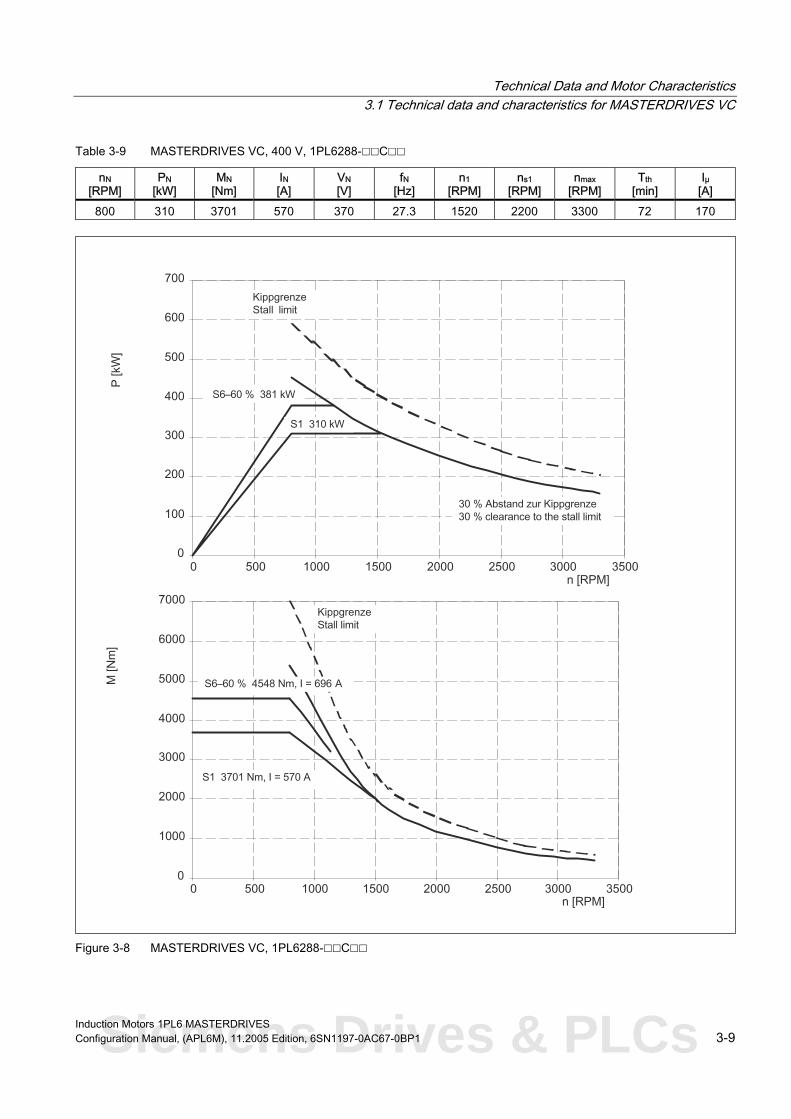
Technical Data and Motor Characteristics 3.1 Technical data and characteristics for MASTERDRIVES VC
Table 3-9 MASTERDRIVES VC, 400 V, 1PL6288-C
nN [RPM]
PN [kW]
MN [Nm]
IN [A]
VN [V]
fN [Hz]
n1 [RPM]
ns1 [RPM]
nmax Tth [min]
Iμ [A]
800 310 3701 570 370 27.3 2200 3300 72 170
[RPM]
1520
Figure 3-8 MASTERDRIVES VC, 1PL6288-C
Induction Motors 1PL6 MASTERDRIVES Configuration Manual, (APL6M), 11.2005 Edition, 6SN1197-0AC67-0BP1 3-9 Siemens Drives & PLCs

Technical Data and Motor Characteristics 3.1 Technical data and characteristics for MASTERDRIVES VC
Table 3-10 MASTERDRIVES VC, 400 V, 1PL6184-D
nN [RPM]
PN [kW]
MN [Nm]
IN [A]
VN [V]
fN [Hz]
n1 [RPM]
ns1 [RPM]
nmax Tth [min]
Iμ [A]
1150 65 540 121 400 39.4 1750 3500 1) 5000 30 46
[RPM]
F igure 3-9 MASTERDRIVES VC, 1PL6184-D
1) 3000 RPM for increased cantilever forces
Induction Motors 1PL6 MASTERDRIVES 3-10 Configuration Manual, (APL6M), 11.2005 Edition, 6SN1197-0AC67-0BP1

Technical Data and Motor Characteristics 3.1 Technical data and characteristics for MASTERDRIVES VC
Table 3-11 MASTERDRIVES VC, 400 V, 1PL6186-D
nN [RPM]
PN [kW]
MN [Nm]
IN [A]
VN [V]
fN [Hz]
n1 [RPM]
ns1 [RPM]
nmax Tth [min]
Iμ [A]
1150 85 706 158 400 39.4 1950 3500 1) 5000 30 62
[RPM]
F igure 3-10 MASTERDRIVES VC, 1PL6186-D
1) 3000 RPM for increased cantilever forces
Induction Motors 1PL6 MASTERDRIVES Configuration Manual, (APL6M), 11.2005 Edition, 6SN1197-0AC67-0BP1 3-11 Siemens Drives & PLCs

Technical Data and Motor Characteristics 3.1 Technical data and characteristics for MASTERDRIVES VC
Table 3-12 MASTERDRIVES VC, 400 V, 1PL6224-D
nN [RPM]
PN [kW]
MN [Nm]
IN [A]
VN [V]
fN [Hz]
n1 [RPM]
ns1 [RPM]
nmax Tth [min]
Iμ [A]
1150 120 997 218 400 39.1 2100 3100 1) 4500 30 86
[RPM]
F igure 3-11 MASTERDRIVES VC, 1PL6224-D
1) 2700 RPM for increased cantilever forces
Induction Motors 1PL6 MASTERDRIVES 3-12 Configuration Manual, (APL6M), 11.2005 Edition, 6SN1197-0AC67-0BP1

Technical Data and Motor Characteristics 3.1 Technical data and characteristics for MASTERDRIVES VC
Table 3-13 MASTERDRIVES VC, 400 V, 1PL6226-D
nN [RPM]
PN [kW]
MN [Nm]
IN [A]
VN [V]
fN [Hz]
n1 [RPM]
ns1 [RPM]
nmax Tth [min]
Iμ [A]
1150 155 1287 275 400 39.2 2000 3100 1) 4500 30 92
[RPM]
Figure 3-12 MASTERDRIVES VC, 1PL6226-D
1) 2700 RPM for increased cantilever forces
Induction Motors 1PL6 MASTERDRIVES Configuration Manual, (APL6M), 11.2005 Edition, 6SN1197-0AC67-0BP1 3-13 Siemens Drives & PLCs

Technical Data and Motor Characteristics 3.1 Technical data and characteristics for MASTERDRIVES VC
Table 3-14 MASTERDRIVES VC, 400 V, 1PL6228-D
nN [RPM]
PN [kW]
MN [Nm]
IN [A]
VN [V]
fN [Hz]
n1 [RPM]
ns1 [RPM]
nmax Tth [min]
Iμ [A]
1150 190 1578 334 400 39.2 1850 3100 1) 4500 2) 30 102
[RPM]
F igure 3-13 MASTERDRIVES VC, 1PL6228-D 1) 2500 RPM for increased cantilever forces 2) 4000 RPM for increased cantilever forces
Induction Motors 1PL6 MASTERDRIVES 3-14 Configuration Manual, (APL6M), 11.2005 Edition, 6SN1197-0AC67-0BP1

Technical Data and Motor Characteristics 3.1 Technical data and characteristics for MASTERDRIVES VC
Table 3-15 MASTERDRIVES VC, 400 V, 1PL6284-D
nN [RPM]
PN [kW]
MN [Nm]
IN [A]
VN [V]
fN [Hz]
n1 [RPM]
ns1 [RPM]
nmax Tth [min]
Iμ [A]
1150 280 2325 478 400 38.9 2200 2200 3300 53 156
[RPM]
Figure 3-14 MASTERDRIVES VC, 1PL6284-D
Induction Motors 1PL6 MASTERDRIVES Configuration Manual, (APL6M), 11.2005 Edition, 6SN1197-0AC67-0BP1 3-15 Siemens Drives & PLCs

Technical Data and Motor Characteristics 3.1 Technical data and characteristics for MASTERDRIVES VC
Table 3-16 MASTERDRIVES VC, 400 V, 1PL6286-D
nN [RPM]
PN [kW]
MN [Nm]
IN [A]
VN [V]
fN [Hz]
n1 [RPM]
ns1 [RPM]
nmax Tth [min]
Iμ [A]
1150 355 2944 637 380 38.9 2200 2200 3300 65 214
[RPM]
Figure 3-15 MASTERDRIVES VC, 1PL6286-D
Induction Motors 1PL6 MASTERDRIVES 3-16 Configuration Manual, (APL6M), 11.2005 Edition, 6SN1197-0AC67-0BP1

Technical Data and Motor Characteristics 3.1 Technical data and characteristics for MASTERDRIVES VC
Table 3-17 MASTERDRIVES VC, 400 V, 1PL6288-D
nN [RPM]
PN [kW]
MN [Nm]
IN [A]
VN [V]
fN [Hz]
n1 [RPM]
ns1 [RPM]
nmax Tth [min]
Iμ [A]
1150 435 3607 765 385 38.9 2200 2200 3300 72 248
[RPM]
Figure 3-16 MASTERDRIVES VC, 1PL6288-D
Induction Motors 1PL6 MASTERDRIVES Configuration Manual, (APL6M), 11.2005 Edition, 6SN1197-0AC67-0BP1 3-17 Siemens Drives & PLCs

Technical Data and Motor Characteristics 3.1 Technical data and characteristics for MASTERDRIVES VC
Table 3-18 MASTERDRIVES VC, 400 V, 1PL6184-F
nN [RPM]
PN [kW]
MN [Nm]
IN [A]
VN [V]
fN [Hz]
n1 [RPM]
ns1 [RPM]
nmax Tth [min]
Iμ [A]
1750 89 486 166 400 59,3 3500 3500 1) 5000 30 68
[RPM]
Figure 3-17 MASTERDRIVES VC, 1PL6184-F 1) 3000 RPM for increased cantilever forces
Induction Motors 1PL6 MASTERDRIVES 3-18 Configuration Manual, (APL6M), 11.2005 Edition, 6SN1197-0AC67-0BP1

Technical Data and Motor Characteristics 3.1 Technical data and characteristics for MASTERDRIVES VC
Table 3-19 MASTERDRIVES VC, 400 V, 1PL6186-F
nN [RPM]
PN [kW]
MN [Nm]
IN [A]
VN [V]
fN [Hz]
n1 [RPM]
ns1 [RPM]
nmax Tth [min]
Iμ [A]
1750 125 682 231 400 59,3 3400 3500 1) 5000 30 92
[RPM]
Figure 3-18 MASTERDRIVES VC, 1PL6186-F 1) 3000 RPM for increased cantilever forces
Induction Motors 1PL6 MASTERDRIVES Configuration Manual, (APL6M), 11.2005 Edition, 6SN1197-0AC67-0BP1 3-19 Siemens Drives & PLCs

Technical Data and Motor Characteristics 3.1 Technical data and characteristics for MASTERDRIVES VC
Table 3-20 MASTERDRIVES VC, 400 V, 1PL6224-F
nN [RPM]
PN [kW]
MN [Nm]
IN [A]
VN [V]
fN [Hz]
n1 [RPM]
ns1 [RPM]
nmax Tth [min]
Iμ [A]
1750 165 900 292 400 59,2 3000 3100 1) 4500 30 90
[RPM]
Figure 3-19 MASTERDRIVES VC, 1PL6224-F
1) 2700 RPM for increased cantilever forces
Induction Motors 1PL6 MASTERDRIVES 3-20 Configuration Manual, (APL6M), 11.2005 Edition, 6SN1197-0AC67-0BP1

Technical Data and Motor Characteristics 3.1 Technical data and characteristics for MASTERDRIVES VC
Table 3-21 MASTERDRIVES VC, 400 V, 1PL6226-F
nN [RPM]
PN [kW]
MN [Nm]
IN [A]
VN [V]
fN [Hz]
n1 [RPM]
ns1 [RPM]
nmax Tth [min]
Iμ [A]
1750 200 1091 350 400 59,1 2900 3100 1) 4500 30 122
[RPM]
Figure 3-20 MASTERDRIVES VC, 1PL6226-F
1) 2700 RPM for increased cantilever forces
Induction Motors 1PL6 MASTERDRIVES Configuration Manual, (APL6M), 11.2005 Edition, 6SN1197-0AC67-0BP1 3-21 Siemens Drives & PLCs

Technical Data and Motor Characteristics 3.1 Technical data and characteristics for MASTERDRIVES VC
Table 3-22 MASTERDRIVES VC, 400 V, 1PL6228-F
nN [RPM]
PN [kW]
MN [Nm]
IN [A]
VN [V]
fN [Hz]
n1 [RPM]
ns1 [RPM]
nmax Tth [min]
Iμ [A]
1750 265 1446 470 400 59.0 2900 3100 1) 4500 2) 30 174
[RPM]
F igure 3-21 MASTERDRIVES VC, 1PL6228-F
1) 2500 RPM for increased cantilever forces 2) 4000 RPM for increased cantilever forces
Induction Motors 1PL6 MASTERDRIVES 3-22 Configuration Manual, (APL6M), 11.2005 Edition, 6SN1197-0AC67-0BP1

Technical Data and Motor Characteristics 3.1 Technical data and characteristics for MASTERDRIVES VC
Table 3-23 MASTERDRIVES VC, 400 V, 1PL6284-F
nN [RPM]
PN [kW]
MN [Nm]
IN [A]
VN [V]
fN [Hz]
n1 [RPM]
ns1 [RPM]
nmax Tth [min]
Iμ [A]
1750 370 2019 616 400 59.0 2200 2200 3300 53 162
[RPM]
n [RPM]
P [
kW]
M [N
m]
0
100
200
300
400
500
600
700
800
900
0 500 1000 1500 2000 2500 3000 3500 4000
0
500
1000
1500
2000
2500
3000
3500
4000
0 500 1000 1500 2000 2500 3000 3500 4000
Kippgrenzebreakdown limit
30 % Abstand zur Kippgrenze30 % margin to breakdown limit
S1 370 kW
Kippgrenzebreakdown limit
S6–60 % 2443 Nm, I = 755 A
S1 2019 Nm, I = 616 A
S6–40 % 544 kW
S6–60 % 455 kW
S6–40 % 2969 Nm, I = 906 A
n [RPM]
Figure 3-22 MASTERDRIVES VC, 1PL6284-F
Induction Motors 1PL6 MASTERDRIVES Configuration Manual, (APL6M), 11.2005 Edition, 6SN1197-0AC67-0BP1 3-23 Siemens Drives & PLCs

Technical Data and Motor Characteristics 3.1 Technical data and characteristics for MASTERDRIVES VC
Table 3-24 MASTERDRIVES VC, 400 V, 1PL6286-F
nN [RPM]
PN [kW]
MN [Nm]
IN [A]
VN [V]
fN [Hz]
n1 [RPM]
ns1 [RPM]
nmax Tth [min]
Iμ [A]
1750 445 2429 736 400 59.0 2200 2200 3300 65 182
[RPM]
P [k
W]
M [N
m]
0
200
400
600
800
1000
1200
0 500 1000 1500 2000 2500 3000 3500 4000
0
500
1000
1500
2000
2500
3000
3500
4000
4500
5000
0 500 1000 1500 2000 2500 3000 3500 4000
KippgrenzeStall limit
30 % Abstand zur Kippgrenze30 % clearance to the stall limit
S1 445 kW
KippgrenzeStall limit
S6–60 % 2985 Nm, I = 903 A
S1 2429 Nm, I = 736 A
S6–40 % 654 kW
S6–60 % 547 kW
S6–40 % 3569 Nm, I = 1085 A
n [RPM]
n [RPM]
Figure 3-23 MASTERDRIVES VC, 1PL6286-F
Induction Motors 1PL6 MASTERDRIVES 3-24 Configuration Manual, (APL6M), 11.2005 Edition, 6SN1197-0AC67-0BP1

Technical Data and Motor Characteristics 3.1 Technical data and characteristics for MASTERDRIVES VC
Table 3-25 MASTERDRIVES VC, 400 V, 1PL6288-F
nN [RPM]
PN [kW]
MN [Nm]
IN [A]
VN [V]
fN [Hz]
n1 [RPM]
ns1 [RPM]
nmax Tth [min]
Iμ [A]
1750 560 3055 924 400 59.0 2200 2200 3300 72 232
[RPM] P
[kW
]M
[Nm
]
0
200
400
600
800
1000
1200
1400
1600
0 500 1000 1500 2000 2500 3000 3500 4000
0
1000
2000
3000
4000
5000
6000
0 500 1000 1500 2000 2500 3000 3500 4000
KippgrenzeStall limit
30 % Abstand zur Kippgrenze30 % clearance to the stall limit
S1 560 kW
KippgrenzeStall limit
S6–60 % 3760 Nm, I = 1 133 A
S1 3055 Nm, I = 924 A
S6–40 % 823 kW
S6–60 % 689 kW
S6–40 % 4491 Nm, I = 1362 A
n [RPM]
n [RPM]
Figure 3-24 MASTERDRIVES VC, 1PL6288-F
Induction Motors 1PL6 MASTERDRIVES Configuration Manual, (APL6M), 11.2005 Edition, 6SN1197-0AC67-0BP1 3-25 Siemens Drives & PLCs

Technical Data and Motor Characteristics 3.1 Technical data and characteristics for MASTERDRIVES VC
Table 3-26 MASTERDRIVES VC, 400 V, 1PL6184-L
nN [RPM]
PN [kW]
MN [Nm]
IN [A]
VN [V]
fN [Hz]
n1 [RPM]
ns1 [RPM]
nmax Tth [min]
Iμ [A]
2900 113 372 209 400 97.6 5000 3500 1) 5000 30 79
[RPM]
F igure 3-25 MASTERDRIVES VC, 1PL6184-L
1) 3000 RPM for increased cantilever forces
Induction Motors 1PL6 MASTERDRIVES 3-26 Configuration Manual, (APL6M), 11.2005 Edition, 6SN1197-0AC67-0BP1

Technical Data and Motor Characteristics 3.1 Technical data and characteristics for MASTERDRIVES VC
Table 3-27 MASTERDRIVES VC, 400 V, 1PL6186-L
nN [RPM]
PN [kW]
MN [Nm]
IN [A]
VN [V]
fN [Hz]
n1 [RPM]
ns1 [RPM]
nmax Tth [min]
Iμ [A]
2900 150 494 280 390 97,5 5000 3500 1) 5000 30 110
[RPM]
Figure 3-26 MASTERDRIVES VC, 1PL6186-L 1) 3000 RPM for increased cantilever forces
Induction Motors 1PL6 MASTERDRIVES Configuration Manual, (APL6M), 11.2005 Edition, 6SN1197-0AC67-0BP1 3-27 Siemens Drives & PLCs

Technical Data and Motor Characteristics 3.1 Technical data and characteristics for MASTERDRIVES VC
Table 3-28 MASTERDRIVES VC, 400 V, 1PL6224-L
nN [RPM]
PN [kW]
MN [Nm]
IN [A]
VN [V]
fN [Hz]
n1 [RPM]
ns1 [RPM]
nmax Tth [min]
Iμ [A]
2900 205 675 365 400 97,5 3500 3100 1) 4500 30 118
[RPM]
0
25
50
75
100
125
150
175
200
225
250
275
300
325
350
375
0 500 1000 1500 2000 2500 3000 3500 4000 4500
0
100
200
300
400
500
600
700
800
900
1000
1100
1200
1300
0 500 1000 1500 2000 2500 3000 3500 4000 4500
F igure 3-27 MASTERDRIVES VC, 1PL6224-L
1) 2700 RPM for increased cantilever forces
Induction Motors 1PL6 MASTERDRIVES 3-28 Configuration Manual, (APL6M), 11.2005 Edition, 6SN1197-0AC67-0BP1

Technical Data and Motor Characteristics 3.1 Technical data and characteristics for MASTERDRIVES VC
Table 3-29 MASTERDRIVES VC, 400 V, 1PL6226-L
nN [RPM]
PN [kW]
MN [Nm]
IN [A]
VN [V]
fN [Hz]
n1 [RPM]
ns1 [RPM]
nmax Tth [min]
Iμ [A]
2900 270 889 470 400 97,4 3500 3100 1) 4500 30 160
[RPM]
0
50
100
150
200
250
300
350
400
450
500
0 500 1000 1500 2000 2500 3000 3500 4000 4500
0
200
400
600
800
1000
1200
1400
1600
0 500 1000 1500 2000 2500 3000 3500 4000 4500
Figure 3-28 MASTERDRIVES VC, 1PL6226-L 1) 2700 RPM for increased cantilever forces
Induction Motors 1PL6 MASTERDRIVES Configuration Manual, (APL6M), 11.2005 Edition, 6SN1197-0AC67-0BP1 3-29 Siemens Drives & PLCs

Technical Data and Motor Characteristics 3.1 Technical data and characteristics for MASTERDRIVES VC
Table 3-30 MASTERDRIVES VC, 400 V, 1PL6228-L
nN [RPM]
PN [kW]
MN [Nm]
IN [A]
VN [V]
fN [Hz]
n1 [RPM]
ns1 [RPM]
nmax Tth [min]
Iμ [A]
2900 300 988 530 400 97,3 3500 3100 1) 4500 2) 30 188
[RPM]
0
50
100
150
200
250
300
350
400
450
500
550
0 500 1000 1500 2000 2500 3000 3500 4000 4500
0
200
400
600
800
1000
1200
1400
1600
1800
2000
0 500 1000 1500 2000 2500 3000 3500 4000 4500
F igure 3-29 MASTERDRIVES VC, 1PL6228-L
1) 2500 RPM for increased cantilever forces 2) 4000 RPM for increased cantilever forces
Induction Motors 1PL6 MASTERDRIVES 3-30 Configuration Manual, (APL6M), 11.2005 Edition, 6SN1197-0AC67-0BP1

Technical Data and Motor Characteristics 3.1 Technical data and characteristics for MASTERDRIVES VC
3.1.2 P/n and M/n diagrams for 3-ph. 480 V AC
Table 3-31 MASTERDRIVES VC, 480 V, 1PL6184-B
nN [RPM]
PN [kW]
MN [Nm]
IN [A]
VN [V]
fN [Hz]
n1 [RPM]
ns1 [RPM]
nmax Tth [min]
Iμ [A]
500 30 573 66 370 17.6 1300 2500 2500 30 34
[RPM]
Figure 3-30 MASTERDRIVES VC, 1PL6184-B
Induction Motors 1PL6 MASTERDRIVES Configuration Manual, (APL6M), 11.2005 Edition, 6SN1197-0AC67-0BP1 3-31 Siemens Drives & PLCs

Technical Data and Motor Characteristics 3.1 Technical data and characteristics for MASTERDRIVES VC
Table 3-32 MASTERDRIVES VC, 480 V, 1PL6186-B
nN [RPM]
PN [kW]
MN [Nm]
IN [A]
VN [V]
fN [Hz]
n1 [RPM]
ns1 [RPM]
nmax Tth [min]
Iμ [A]
500 40 764 91 355 17.6 1500 2500 2500 30 46
[RPM]
Figure 3-31 MASTERDRIVES VC, 1PL6186-B
Induction Motors 1PL6 MASTERDRIVES 3-32 Configuration Manual, (APL6M), 11.2005 Edition, 6SN1197-0AC67-0BP1

Technical Data and Motor Characteristics 3.1 Technical data and characteristics for MASTERDRIVES VC
Table 3-33 MASTERDRIVES VC, 480 V, 1PL6224-B
nN [RPM]
PN [kW]
MN [Nm]
IN [A]
VN [V]
fN [Hz]
n1 [RPM]
ns1 [RPM]
nmax Tth [min]
Iμ [A]
500 55 1050 114 370 17,5 1300 2500 2500 30 46
[RPM]
Figure 3-32 MASTERDRIVES VC, 1PL6224-B
Induction Motors 1PL6 MASTERDRIVES Configuration Manual, (APL6M), 11.2005 Edition, 6SN1197-0AC67-0BP1 3-33 Siemens Drives & PLCs

Technical Data and Motor Characteristics 3.1 Technical data and characteristics for MASTERDRIVES VC
Table 3-34 MASTERDRIVES VC, 480 V, 1PL6226-B
nN [RPM]
PN [kW]
MN [Nm]
IN [A]
VN [V]
fN [Hz]
n1 [RPM]
ns1 [RPM]
nmax Tth [min]
Iμ [A]
500 72 1375 147 375 17,4 1500 2500 2500 30 66
[RPM]
Figure 3-33 MASTERDRIVES VC, 1PL6226-B
Induction Motors 1PL6 MASTERDRIVES 3-34 Configuration Manual, (APL6M), 11.2005 Edition, 6SN1197-0AC67-0BP1

Technical Data and Motor Characteristics 3.1 Technical data and characteristics for MASTERDRIVES VC
Table 3-35 MASTERDRIVES VC, 480 V, 1PL6228-B
nN [RPM]
PN [kW]
MN [Nm]
IN [A]
VN [V]
fN [Hz]
n1 [RPM]
ns1 [RPM]
nmax Tth [min]
Iμ [A]
500 90 1719 180 380 17,4 1400 2500 2500 30 79
[RPM]
Figure 3-34 MASTERDRIVES VC, 1PL6228-B
Induction Motors 1PL6 MASTERDRIVES Configuration Manual, (APL6M), 11.2005 Edition, 6SN1197-0AC67-0BP1 3-35 Siemens Drives & PLCs

Technical Data and Motor Characteristics 3.1 Technical data and characteristics for MASTERDRIVES VC
Table 3-36 MASTERDRIVES VC, 480 V, 1PL6284-C
nN [RPM]
PN [kW]
MN [Nm]
IN [A]
VN [V]
fN [Hz]
n1 [RPM]
ns1 [RPM]
nmax Tth [min]
Iμ [A]
1000 235 2244 335 480 34.0 1700 2200 3300 53 90
[RPM]
Figure 3-35 MASTERDRIVES VC, 1PL6284-C
Induction Motors 1PL6 MASTERDRIVES 3-36 Configuration Manual, (APL6M), 11.2005 Edition, 6SN1197-0AC67-0BP1

Technical Data and Motor Characteristics 3.1 Technical data and characteristics for MASTERDRIVES VC
Table 3-37 MASTERDRIVES VC, 480 V, 1PL6286-C
nN [RPM]
PN [kW]
MN [Nm]
IN [A]
VN [V]
fN [Hz]
n1 [RPM]
ns1 [RPM]
nmax Tth [min]
Iμ [A]
1000 310 2961 440 480 34.0 2000 2200 3300 65 135
[RPM]
Figure 3-36 MASTERDRIVES VC, 1PL6286-C
Induction Motors 1PL6 MASTERDRIVES Configuration Manual, (APL6M), 11.2005 Edition, 6SN1197-0AC67-0BP1 3-37 Siemens Drives & PLCs

Technical Data and Motor Characteristics 3.1 Technical data and characteristics for MASTERDRIVES VC
Table 3-38 MASTERDRIVES VC, 480 V, 1PL6288-C
nN [RPM]
PN [kW]
MN [Nm]
IN [A]
VN [V]
fN [Hz]
n1 [RPM]
ns1 [RPM]
nmax Tth [min]
Iμ [A]
1000 385 3677 570 460 34.0 2050 2200 3300 72 170
[RPM]
Figure 3-37 MASTERDRIVES VC, 1PL6288-C
Induction Motors 1PL6 MASTERDRIVES 3-38 Configuration Manual, (APL6M), 11.2005 Edition, 6SN1197-0AC67-0BP1

Technical Data and Motor Characteristics 3.1 Technical data and characteristics for MASTERDRIVES VC
Table 3-39 MASTERDRIVES VC, 480 V, 1PL6184-D
nN [RPM]
PN [kW]
MN [Nm]
IN [A]
VN [V]
fN [Hz]
n1 [RPM]
ns1 [RPM]
nmax Tth [min]
Iμ [A]
1350 74 523 119 460 46,1 2200 3500 1) 5000 30 44
[RPM]
P [
kW]
M [N
m]
0
10
20
30
40
50
60
70
80
90
100
110
120
130
140
150
0 500 1000 1500 2000 2500 3000 3500 4000 4500 5000
0
50
100
150
200
250
300
350
400
450
500
550
600
650
700
0 500 1000 1500 2000 2500 3000 3500 4000 4500 5000
KippgrenzeStall limit
30 % Abstand zur Kippgrenze30 % clearance to the stall limit
KippgrenzeStall limit
n [RPM]
n [RPM]
S1 74 kW
S6–60 % 637 Nm, I = 143 A
S1 523 Nm, I = 1 19 A
S6–60 % 90 kW
max. stall torqueat 460 V: 955 Nm
Stall limit at460 V: 955 Nm
Figure 3-38 MASTERDRIVES VC, 1PL6184-D 1) 3000 RPM for increased cantilever forces
Induction Motors 1PL6 MASTERDRIVES Configuration Manual, (APL6M), 11.2005 Edition, 6SN1197-0AC67-0BP1 3-39 Siemens Drives & PLCs

Technical Data and Motor Characteristics 3.1 Technical data and characteristics for MASTERDRIVES VC
Table 3-40 MASTERDRIVES VC, 480 V, 1PL6186-D
nN [RPM]
PN [kW]
MN [Nm]
IN [A]
VN [V]
fN [Hz]
n1 [RPM]
ns1 [RPM]
nmax Tth [min]
Iμ [A]
1350 98 693 156 460 46.0 2400 3500 1) 5000 30 60
[RPM]
F igure 3-39 MASTERDRIVES VC, 1PL6186-D
1) 3000 RPM for increased cantilever forces
Induction Motors 1PL6 MASTERDRIVES 3-40 Configuration Manual, (APL6M), 11.2005 Edition, 6SN1197-0AC67-0BP1

Technical Data and Motor Characteristics 3.1 Technical data and characteristics for MASTERDRIVES VC
Table 3-41 MASTERDRIVES VC, 480 V, 1PL6224-D
nN [RPM]
PN [kW]
MN [Nm]
IN [A]
VN [V]
fN [Hz]
n1 [RPM]
ns1 [RPM]
nmax Tth [min]
Iμ [A]
1350 137 969 215 460 45.8 2500 3100 1) 4500 30 82
[RPM]
0
20
40
60
80
100
120
140
160
180
200
220
240
260
0 500 1000 1500 2000 2500 3000 3500 4000 4500
0
200
400
600
800
1000
1200
1400
1600
1800
0 500 1000 1500 2000 2500 3000 3500 4000 4500
Figure 3-40 MASTERDRIVES VC, 1PL6224-D 1) 2700 RPM for increased cantilever forces
Induction Motors 1PL6 MASTERDRIVES Configuration Manual, (APL6M), 11.2005 Edition, 6SN1197-0AC67-0BP1 3-41 Siemens Drives & PLCs

Technical Data and Motor Characteristics 3.1 Technical data and characteristics for MASTERDRIVES VC
Table 3-42 MASTERDRIVES VC, 480 V, 1PL6226-D
nN [RPM]
PN [kW]
MN [Nm]
IN [A]
VN [V]
fN [Hz]
n1 [RPM]
ns1 [RPM]
nmax Tth [min]
Iμ [A]
1350 172 1217 265 460 45.8 2500 3100 1) 4500 30 88
[RPM]
0
25
50
75
100
125
150
175
200
225
250
275
300
325
0 500 1000 1500 2000 2500 3000 3500 4000 4500
0
200
400
600
800
1000
1200
1400
1600
1800
2000
2200
2400
0 500 1000 1500 2000 2500 3000 3500 4000 4500
F igure 3-41 MASTERDRIVES VC, 1PL6226-D
1) 2700 RPM for increased cantilever forces
Induction Motors 1PL6 MASTERDRIVES 3-42 Configuration Manual, (APL6M), 11.2005 Edition, 6SN1197-0AC67-0BP1
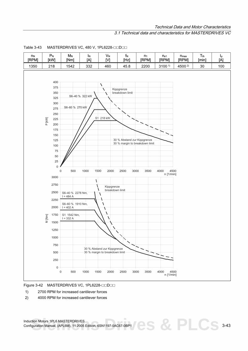
Technical Data and Motor Characteristics 3.1 Technical data and characteristics for MASTERDRIVES VC
Table 3-43 MASTERDRIVES VC, 480 V, 1PL6228-D
nN [RPM]
PN [kW]
MN [Nm]
IN [A]
VN [V]
fN [Hz]
n1 [RPM]
ns1 [RPM]
nmax Tth [min]
Iμ [A]
1350 218 1542 332 460 45.8 2200 3100 1) 4500 2) 30 100
[RPM]
0
25
50
75
100
125
150
175
200
225
250
275
300
325
350
375
400
0 500 1000 1500 2000 2500 3000 3500 4000 4500
0
250
500
750
1000
1250
1500
1750
2000
2250
2500
2750
3000
0 500 1000 1500 2000 2500 3000 3500 4000 4500
F igure 3-42 MASTERDRIVES VC, 1PL6228-D
1) 2700 RPM for increased cantilever forces 2) 4000 RPM for increased cantilever forces
Induction Motors 1PL6 MASTERDRIVES Configuration Manual, (APL6M), 11.2005 Edition, 6SN1197-0AC67-0BP1 3-43 Siemens Drives & PLCs

Technical Data and Motor Characteristics 3.1 Technical data and characteristics for MASTERDRIVES VC
Table 3-44 MASTERDRIVES VC, 480 V, 1PL6284-D
nN [RPM]
PN [kW]
MN [Nm]
IN [A]
VN [V]
fN [Hz]
n1 [RPM]
ns1 [RPM]
nmax Tth [min]
Iμ [A]
1350 325 2299 478 470 45.5 2200 2200 3300 53 157
[RPM]
Figure 3-43 MASTERDRIVES VC, 1PL6284-D
Induction Motors 1PL6 MASTERDRIVES 3-44 Configuration Manual, (APL6M), 11.2005 Edition, 6SN1197-0AC67-0BP1

Technical Data and Motor Characteristics 3.1 Technical data and characteristics for MASTERDRIVES VC
Table 3-45 MASTERDRIVES VC, 480 V, 1PL6286-D
nN [RPM]
PN [kW]
MN [Nm]
IN [A]
VN [V]
fN [Hz]
n1 [RPM]
ns1 [RPM]
nmax Tth [min]
Iμ [A]
1350 410 2901 637 445 45.5 2200 2200 3300 65 215
[RPM]
Figure 3-44 MASTERDRIVES VC, 1PL6286-D
Induction Motors 1PL6 MASTERDRIVES Configuration Manual, (APL6M), 11.2005 Edition, 6SN1197-0AC67-0BP1 3-45 Siemens Drives & PLCs

Technical Data and Motor Characteristics 3.1 Technical data and characteristics for MASTERDRIVES VC
Table 3-46 MASTERDRIVES VC, 480 V, 1PL6288-D
nN [RPM]
PN [kW]
MN [Nm]
IN [A]
VN [V]
fN [Hz]
n1 [RPM]
ns1 [RPM]
nmax Tth [min]
Iμ [A]
1350 505 3573 765 450 45.5 2200 2200 3300 72 248
[RPM]
Figure 3-45 MASTERDRIVES VC, 1PL6288-D
Induction Motors 1PL6 MASTERDRIVES 3-46 Configuration Manual, (APL6M), 11.2005 Edition, 6SN1197-0AC67-0BP1

Technical Data and Motor Characteristics 3.1 Technical data and characteristics for MASTERDRIVES VC
Table 3-47 MASTERDRIVES VC, 480 V, 1PL6184-F
nN [RPM]
PN [kW]
MN [Nm]
IN [A]
VN [V]
fN [Hz]
n1 [RPM]
ns1 [RPM]
nmax Tth [min]
Iμ [A]
2000 98 468 161 460 67.5 4200 3500 1) 5000 30 70
[RPM]
F igure 3-46 MASTERDRIVES VC, 1PL6184-F
1) 3000 RPM for increased cantilever forces
Induction Motors 1PL6 MASTERDRIVES Configuration Manual, (APL6M), 11.2005 Edition, 6SN1197-0AC67-0BP1 3-47 Siemens Drives & PLCs

Technical Data and Motor Characteristics 3.1 Technical data and characteristics for MASTERDRIVES VC
Table 3-48 MASTERDRIVES VC, 480 V, 1PL6186-F
nN [RPM]
PN [kW]
MN [Nm]
IN [A]
VN [V]
fN [Hz]
n1 [RPM]
ns1 [RPM]
nmax Tth [min]
Iμ [A]
2000 135 645 220 460 67.5 4200 3500 1) 5000 30 94
[RPM]
F igure 3-47 MASTERDRIVES VC, 1PL6186-F
1) 3000 RPM for increased cantilever forces
Induction Motors 1PL6 MASTERDRIVES 3-48 Configuration Manual, (APL6M), 11.2005 Edition, 6SN1197-0AC67-0BP1

Technical Data and Motor Characteristics 3.1 Technical data and characteristics for MASTERDRIVES VC
Table 3-49 MASTERDRIVES VC, 480 V, 1PL6224-F
nN [RPM]
PN [kW]
MN [Nm]
IN [A]
VN [V]
fN [Hz]
n1 [RPM]
ns1 [RPM]
nmax Tth [min]
Iμ [A]
2000 178 850 275 460 67.5 2900 3100 1) 4500 30 91
[RPM]
0
25
50
75
100
125
150
175
200
225
250
275
300
325
350
0 500 1000 1500 2000 2500 3000 3500 4000 4500
0
200
400
600
800
1000
1200
1400
1600
1800
0 500 1000 1500 2000 2500 3000 3500 4000 4500
Figure 3-48 MASTERDRIVES VC, 1PL6224-F
2700 RPM for increased cantilever forces 1)
Induction Motors 1PL6 MASTERDRIVES Configuration Manual, (APL6M), 11.2005 Edition, 6SN1197-0AC67-0BP1 3-49 Siemens Drives & PLCs

Technical Data and Motor Characteristics 3.1 Technical data and characteristics for MASTERDRIVES VC
Table 3-50 MASTERDRIVES VC, 480 V, 1PL6226-F
nN [RPM]
MN [Nm]
VN [V]
n1 [RPM]
nmax [RPM]
Iμ [A]
PN [kW]
IN [A]
fN [Hz]
ns1 [RPM]
Tth [min]
1) 2000 220 1050 342 460 67.5 2900 3100 4500 30 124
0
25
50
75
100
125
150
175
200
225
250
275
300
325
350
375
400
0 500 1000 1500 2000 2500 3000 3500 4000 4500
0
200
400
600
800
1000
1200
1400
1600
1800
2000
0 500 1000 1500 2000 2500 3000 3500 4000 4500
Figure 3-49 MASTERDRIVES VC, 1PL6226-F
1) 2700 RPM for increased cantilever forces
Induction Motors 1PL6 MASTERDRIVES 3-50 Configuration Manual, (APL6M), 11.2005 Edition, 6SN1197-0AC67-0BP1

Technical Data and Motor Characteristics 3.1 Technical data and characteristics for MASTERDRIVES VC
Table 3-51 MASTERDRIVES VC, 480 V, 1PL6228-F
nN [RPM]
PN [kW]
MN [Nm]
IN [A]
n1 [RPM]
n[RPM]
VN [V]
fN [Hz]
s1 nmax
Iμ
3100 1) 4500 2)
[RPM]Tth
[min] [A]
2000 288 1375 450 460 67.3 2900 30 176
F igure 3-5 MASTERDRIVES VC, 1PL6228-F 0
1) 2500 RPM for increased cantilever forces 2) 4000 RPM for increased cantilever forces
Induction Motors 1PL6 MASTERDRIVES Configuration Manual, (APL6M), 11.2005 Edition, 6SN1197-0AC67-0BP1 3-51 Siemens Drives & PLCs

Technical Data and Motor Characteristics 3.1 Technical data and characteristics for MASTERDRIVES VC
Table 3-52 MASTERDRIVES VC, 480 V, 1PL6284-F
n[RPM]
MN PN [kW]
N [Nm]
IN [A]
VN [V]
fN [Hz]
n1 [RPM]
ns1 [RPM]
nmax Tth [min] [RPM]
Iμ [A]
2000 455 67.3 2200 2200 415 1981 616 3300 53 161
Figure 3-51 MASTERDRIVES VC, 1PL6284-F
Induction Motors 1PL6 MASTERDRIVES 3-52 Configuration Manual, (APL6M), 11.2005 Edition, 6SN1197-0AC67-0BP1

Technical Data and Motor Characteristics 3.1 Technical data and characteristics for MASTERDRIVES VC
Table 3-53 MASTERDRIVES VC, 480 V, 1PL6286-F
nN [RPM]
PN [kW]
IN [A]
VN [V]
fN [Hz]
n1 [RPM]
nmax
Tth [min]
Iμ [A]
MN [Nm]
ns1 [RPM] [RPM]
2000 500 2387 736 455 67.3 2200 2200 3300 65 181
Figure 3-52 MASTERDRIVES VC, 1PL6286-F
Induction Motors 1PL6 MASTERDRIVES Configuration Manual, (APL6M), 11.2005 Edition, 6SN1197-0AC67-0BP1 3-53 Siemens Drives & PLCs

Technical Data and Motor Characteristics 3.1 Technical data and characteristics for MASTERDRIVES VC
Table 3-54 MASTERDRIVES VC, 480 V, 1PL6288-F
nN [RPM]
PN [kW]
MN [Hz]
[Nm]
IN [A]
VN [V]
fN n1 [RPM]
ns1 [RPM]
nmax Tth [min] [RPM]
Iμ [A]
2000 630 3009 924 455 67.3 2200 2200 3300 72 231
Figure 3-53 MASTERDRIVES VC, 1PL6288-F
Induction Motors 1PL6 MASTERDRIVES 3-54 Configuration Manual, (APL6M), 11.2005 Edition, 6SN1197-0AC67-0BP1

Technical Data and Motor Characteristics 3.1 Technical data and characteristics for MASTERDRIVES VC
Table 3-55 MASTERDRIVES VC, 480 V, 1PL6184-L
nN [RPM]
PN [kW]
IN [A]
VN [V]
fN [Hz]
n1 [RPM]
ns1 [RPM]
max Tth [min]
Iμ [A]
3500 1)
MN [Nm]
n[RPM]
2900 113 372 209 400 97.6 5000 5000 30 79
Figure 3-54 MASTERDRIVES VC, 1PL6184-L 1) 3000 RPM for increased cantilever forces
Induction Motors 1PL6 MASTERDRIVES Configuration Manual, (APL6M), 11.2005 Edition, 6SN1197-0AC67-0BP1 3-55 Siemens Drives & PLCs

Technical Data and Motor Characteristics 3.1 Technical data and characteristics for MASTERDRIVES VC
Induction Motors 1PL6 MASTERDRIVES 3-56 Configuration Manual, (APL6M), 11.2005 Edition, 6SN1197-0AC67-0BP1
Table 3-56 MASTERDRIVES VC, 480 V, 1PL6186-L
nN [RPM]
PN [kW]
MN [Nm]
IN [A]
VN [V]
fN [Hz]
n1 [RPM]
ns1 [RPM]
nmax [RPM]
Tth [min]
Iμ [A]
2900 150 494 280 390 97.5 5000 3500 1) 5000 30 110
Figure 3-55 MASTERDRIVES VC, 1PL6186-L
1) 3000 RPM for increased cantilever forces

Technical Data and Motor Characteristics 3.1 Technical data and characteristics for MASTERDRIVES VC
Table 3-57 MASTERDRIVES VC, 480 V, 1PL6224-L
nN [RPM]
PN [kW]
MN [Nm]
n[RPM]
IN [A]
VN [V]
fN [Hz]
n1 [RPM]
ns1 [RPM]
max Tth [min]
Iμ [A]
3100 1) 2900 205 675 365 400 97.5 3500 4500 30 118
Figure 3-56 MASTERDRIVES VC, 1PL6224-L 1) 2700 RPM for increased cantilever forces
Induction Motors 1PL6 MASTERDRIVES Configuration Manual, (APL6M), 11.2005 Edition, 6SN1197-0AC67-0BP1 3-57 Siemens Drives & PLCs

Technical Data and Motor Characteristics 3.1 Technical data and characteristics for MASTERDRIVES VC
Table 3-58 MASTERDRIVES VC, 480 V, 1PL6226-L
nN [RPM]
PN [kW]
IN [A]
VN [V]
fN [Hz]
n1 [RPM]
ns1 [RPM]
th Iμ [A]
MN [Nm]
nmax [RPM]
T[min]
2900 270 395 3100 1) 30 160 889 470 97.4 3500 4500
F 7 1) 2700 RPM for increased cantilever forces
igure 3-5 MASTERDRIVES VC, 1PL6226-L
Induction Motors 1PL6 MASTERDRIVES 3-58 Configuration Manual, (APL6M), 11.2005 Edition, 6SN1197-0AC67-0BP1

Technical Data and Motor Characteristics 3.1 Technical data and characteristics for MASTERDRIVES VC
Table 3-59 MASTERDRIVES VC, 480 V, 1PL6228-L
nN [RPM]
P[kW]
N MN VN [V]
[Nm]
IN [A]
fN [Hz]
n1 [RPM]
ns1 [RPM]
nmax
Iμ
4500 2)
[RPM]Tth
[min] [A]
2900 300 3100 1) 988 530 400 97.3 3500 30 188
F igure 3-5 MASTERDRIVES VC, 1PL6228-L 8
2) 1) 2500 RPM for increased cantilever forces
4000 RPM for increased cantilever forces
Induction Motors 1PL6 MASTERDRIVES Configuration Manual, (APL6M), 11.2005 Edition, 6SN1197-0AC67-0BP1 3-59 Siemens Drives & PLCs

Technical Data and Motor Characteristics 3.1 Technical data and characteristics for MASTERDRIVES VC
Induction Motors 1PL6 MASTERDRIVES 3-60 Configuration Manual, (APL6M), 11.2005 Edition, 6SN1197-0AC67-0BP1
3.1.3 P/n and M/n diagrams for 3-ph. 690 V AC
Table 3-60 MASTERDRIVES VC, 690 V, 1PL6284-C (Option C30)
nN [RPM]
PN [kW]
MN [Nm]
IN [A]
VN [V]
fN [Hz]
n1 [RPM]
ns1 [RPM]
nmax [RPM]
Tth [min]
Iμ [A]
800 185 2208 185 690 27.0 1440 2200 3300 53 55
Figure 3-59 MASTERDRIVES VC, 1PL6284-C

Technical Data and Motor Characteristics 3.1 Technical data and characteristics for MASTERDRIVES VC
Table 3-61 MASTERDRIVES VC, 690 V, 1PL6286-C (Option C30)
nN [RPM]
P[kW]
N MN n[RPM]
[Nm]
IN [A]
VN [V]
fN [Hz]
1 ns1 [RPM]
nmax
Tth [min]
Iμ [A] [RPM]
800 240 2865 250 665 65 27.0 1550 2200 3300 80
Figure 3-60 MASTERDRIVES VC, 1PL6286-C
Induction Motors 1PL6 MASTERDRIVES Configuration Manual, (APL6M), 11.2005 Edition, 6SN1197-0AC67-0BP1 3-61 Siemens Drives & PLCs

Technical Data and Motor Characteristics 3.1 Technical data and characteristics for MASTERDRIVES VC
Table 3-62 MASTERDRIVES VC, 690 V, 1PL6288-C (Option C30)
MnN [RPM]
PN [kW]
N [Nm] [Hz]
IN [A]
VN [V]
fN n1 [RPM]
ns1 [RPM]
nmax Tth [min]
Iμ [A] [RPM]
800 300 3581 320 640 27.0 1600 2200 3300 72 100
Figure 3-61 MASTERDRIVES VC, 1PL6288-C
Induction Motors 1PL6 MASTERDRIVES 3-62 Configuration Manual, (APL6M), 11.2005 Edition, 6SN1197-0AC67-0BP1

Technical Data and Motor Characteristics 3.1 Technical data and characteristics for MASTERDRIVES VC
Table 3-63 MASTERDRIVES VC, 690 V, 1PL6284-D(Option C30)
nN [RPM]
PN [kW]
MN [Hz]
[Nm]
IN [A]
VN [V]
fN n1 [RPM]
ns1 [RPM]
nmax
Tth [min]
Iμ [A] [RPM]
1150 272 2259 270 690 38.9 2200 2200 3300 53 89
Figure 3-62 MASTERDRIVES VC, 1PL6284-D (Option C30)
Induction Motors 1PL6 MASTERDRIVES Configuration Manual, (APL6M), 11.2005 Edition, 6SN1197-0AC67-0BP1 3-63 Siemens Drives & PLCs

Technical Data and Motor Characteristics 3.1 Technical data and characteristics for MASTERDRIVES VC
Table 3-64 MASTERDRIVES VC, 690 V, 1PL6286-D (Option C30)
nN [RPM]
PN [kW]
MN [Hz]
[Nm]
IN [A]
VN [V]
fN n1 [RPM]
ns1 [RPM]
nmax Tth [min]
Iμ [A] [RPM]
1150 344 2857 359 655 38.9 2200 2200 3300 65 123
Figure 3-63 MASTERDRIVES VC, 1PL6286-D (Option C30)
Induction Motors 1PL6 MASTERDRIVES 3-64 Configuration Manual, (APL6M), 11.2005 Edition, 6SN1197-0AC67-0BP1

Technical Data and Motor Characteristics 3.1 Technical data and characteristics for MASTERDRIVES VC
Table 3-65 MASTERDRIVES VC, 690 V, 1PL6288-D (Option C30)
nN [RPM]
PN [kW]
MN [Hz]
[Nm]
IN [A]
VN [V]
fN n1 [RPM]
ns1 [RPM]
nmax
Tth [min]
Iμ [A] [RPM]
1150 422 3504 431 665 38.9 2200 2200 3300 72 143
Figure 3-64 MASTERDRIVES VC, 1PL6288-D (Option C30)
Induction Motors 1PL6 MASTERDRIVES Configuration Manual, (APL6M), 11.2005 Edition, 6SN1197-0AC67-0BP1 3-65 Siemens Drives & PLCs

Technical Data and Motor Characteristics 3.1 Technical data and characteristics for MASTERDRIVES VC
Table 3-66 MASTERDRIVES VC, 690 V, 1PL6284-F (Option C30)
nN [RPM]
PN [kW]
MN [Hz]
[Nm]
IN [A]
VN [V]
fN n1 [RPM]
ns1 [RPM]
nmax Tth [min]
Iμ [A] [RPM]
1750 359 1959 347 690 59.0 2200 2200 3300 53 93
Figure 3-65 MASTERDRIVES VC, 1PL6284-F (Option C30)
Induction Motors 1PL6 MASTERDRIVES 3-66 Configuration Manual, (APL6M), 11.2005 Edition, 6SN1197-0AC67-0BP1

Technical Data and Motor Characteristics 3.1 Technical data and characteristics for MASTERDRIVES VC
Table 3-67 MASTERDRIVES VC, 690 V, 1PL6286-F (Option C30)
nN [RPM]
PN [kW]
MN [Hz]
[Nm]
IN [A]
VN [V]
fN n1 [RPM]
ns1 [RPM]
nmax
Tth [min]
Iμ [A] [RPM]
1750 432 2357 415 690 59.0 2200 2200 3300 65 105
Figure 3-66 MASTERDRIVES VC, 1PL6286-F (Option C30)
Induction Motors 1PL6 MASTERDRIVES Configuration Manual, (APL6M), 11.2005 Edition, 6SN1197-0AC67-0BP1 3-67 Siemens Drives & PLCs

Technical Data and Motor Characteristics 3.1 Technical data and characteristics for MASTERDRIVES VC
Table 3-68 MASTERDRIVES VC, 690 V, 1PL6288-F (Option C30)
nN [RPM]
PN [kW]
MN [Hz]
[Nm]
IN [A]
VN [V]
fN n1 [RPM]
ns1 [RPM]
nmax Tth [min]
Iμ [A] [RPM]
1750 543 2963 520 690 59.0 2200 2200 3300 72 133
Figure 3-67 MASTERDRIVES VC, 1PL6288-F (Option C30)
Induction Motors 1PL6 MASTERDRIVES 3-68 Configuration Manual, (APL6M), 11.2005 Edition, 6SN1197-0AC67-0BP1

Technical Data and Motor Characteristics 3.2 Technical data and characteristics for MASTERDRIVES MC
3.2 3.2 Technical data and characteristics for MASTERDRIVES MC 3.2.1 P/n diagrams for 3-ph. 400 V AC Table 3-69 MASTERDRIVES MC, 400 V, 1PL6184-B
nN [RPM]
PN [kW]
MN V[V]
n1 [RPM]
ns1 [RPM]
nmax [RPM]
Tth [min]
Iμ [A]
[Nm]
IN [A]
N f [Hz]
N
400 20.5 489 58 290 14.2 800 800 800 30 33.4
0
50
100
150
200
250
300
350
400
450
500
550
600
650
700
0 500 1000 1500 2000 2500 3000 3500 4000 4500 5000
0
5
10
15
20
25
30
35
0 500 1000 1500 2000 2500 3000 3500 4000 4500 5000
Figure 3-68 MASTERDRIVES MC, 1PL6184-B
Induction Motors 1PL6 MASTERDRIVES Configuration Manual, (APL6M), 11.2005 Edition, 6SN1197-0AC67-0BP1 3-69 Siemens Drives & PLCs

Technical Data and Motor Characteristics 3.2 Technical data and characteristics for MASTERDRIVES MC
Table 3-70 MASTERDRIVES MC, 400 V, 1PL6186-B
nN [RPM]
P [kW]
MN [Nm]
IN [A]
VN [V]
fN [Hz]
n1 [RPM]
ns1 [RPM]
nmax Tth [min]
Iμ [A]
400 30.5 728 87 290 14.1 800 800 800 30 48.6
N [RPM]
0
5
10
15
20
25
30
35
40
45
50
55
60
0 500 1000 1500 2000 2500 3000 3500 4000 4500 5000
0
100
200
300
400
500
600
700
800
900
1000
0 500 1000 1500 2000 2500 3000 3500 4000 4500 5000
Figure 3-69 MASTERDRIVES MC, 1PL6186-B
Induction Motors 1PL6 MASTERDRIVES 3-70 Configuration Manual, (APL6M), 11.2005 Edition, 6SN1197-0AC67-0BP1

Technical Data and Motor Characteristics 3.2 Technical data and characteristics for MASTERDRIVES MC
Table 3-71 MASTERDRIVES MC, 400 V, 1PL6224-B
nN [RPM]
PN [kW]
MN [Nm]
IN [A]
VN [V]
fN [Hz]
n1 [RPM]
ns1 [RPM]
nmax
Tth [min]
Iμ [A]
400 40 955 105 296 14 800 800 800 30 45.8
[RPM]
Figure 3-70 MASTERDRIVES MC, 1PL6224-B
Induction Motors 1PL6 MASTERDRIVES Configuration Manual, (APL6M), 11.2005 Edition, 6SN1197-0AC67-0BP1 3-71 Siemens Drives & PLCs

Technical Data and Motor Characteristics 3.2 Technical data and characteristics for MASTERDRIVES MC
Table 3-72 MASTERDRIVES MC, 400 V, 1PL6226-B
nN [RPM]
PN [kW]
MN [Nm]
IN [A]
VN [V]
fN [Hz]
n1 [RPM]
ns1 [RPM]
nmax Tth [min]
Iμ [A]
400 57 1361 145 305 14 800 800 800 30 67
[RPM]
Figure 3-71 MASTERDRIVES MC, 1PL6226-B
Induction Motors 1PL6 MASTERDRIVES 3-72 Configuration Manual, (APL6M), 11.2005 Edition, 6SN1197-0AC67-0BP1

Technical Data and Motor Characteristics 3.2 Technical data and characteristics for MASTERDRIVES MC
Table 3-73 MASTERDRIVES MC, 400 V, 1PL6228-B
nN [RPM]
PN [kW]
MN V[V]
[Nm]
IN [A]
N fN [Hz]
n1 [RPM]
ns1 [RPM]
nmax
Tth [min]
Iμ [A]
400 72 1719 181 305 14.1 800 800 800 30 77
[RPM]
Figure 3-72 MASTERDRIVES MC, 1PL6228-B
Induction Motors 1PL6 MASTERDRIVES Configuration Manual, (APL6M), 11.2005 Edition, 6SN1197-0AC67-0BP1 3-73 Siemens Drives & PLCs

Technical Data and Motor Characteristics 3.2 Technical data and characteristics for MASTERDRIVES MC
Table 3-74 MASTERDRIVES MC, 400 V, 1PL6184-D
nN [RPM]
PN [kW]
MN n[RPM]
[Nm]
IN [A]
VN [V]
fN [Hz]
n1 [RPM]
s1 nmax Tth [min]
Iμ [A]
1000 57 544 122 345 34.4 1300 2000 2000 30 45
[RPM]
Figure 3-73 MASTERDRIVES MC, 1PL6184-D
Induction Motors 1PL6 MASTERDRIVES 3-74 Configuration Manual, (APL6M), 11.2005 Edition, 6SN1197-0AC67-0BP1

Technical Data and Motor Characteristics 3.2 Technical data and characteristics for MASTERDRIVES MC
Table 3-75 MASTERDRIVES MC, 400 V, 1PL6186-D
nN [RPM]
PN [kW]
MN [Nm]
IN [A]
VN [V]
fN [Hz]
n1 [RPM]
ns1 [RPM]
nmax
Tth [min]
Iμ [A]
1000 74 707 157 345 34.3 1600 2000 2000 30 61
[RPM]
Figure 3-74 MASTERDRIVES MC, 1PL6186-D
Induction Motors 1PL6 MASTERDRIVES Configuration Manual, (APL6M), 11.2005 Edition, 6SN1197-0AC67-0BP1 3-75 Siemens Drives & PLCs

Technical Data and Motor Characteristics 3.2 Technical data and characteristics for MASTERDRIVES MC
Table 3-76 MASTERDRIVES MC, 400 V, 1PL6224-D
nN [RPM]
PN [kW]
MN [Nm]
IN [A]
VN [V]
fN [Hz]
n1 [RPM]
ns1 [RPM]
nmax Tth [min]
Iμ [A]
1000 105 1003 220 345 34.5 1700 2000 2000 30 86
[RPM]
Figure 3-75 MASTERDRIVES MC, 1PL6224-D
Induction Motors 1PL6 MASTERDRIVES 3-76 Configuration Manual, (APL6M), 11.2005 Edition, 6SN1197-0AC67-0BP1

Technical Data and Motor Characteristics 3.2 Technical data and characteristics for MASTERDRIVES MC
Table 3-77 MASTERDRIVES MC, 400 V, 1PL6226-D
nN [RPM]
PN [kW]
MN [Nm]
IN [A]
VN [V]
fN [Hz]
n1 [RPM]
ns1 [RPM]
nmax
Tth [min]
Iμ [A]
1000 135 1289 278 345 31.1 1700 2000 2000 30 90
[RPM]
Figure 3-76 MASTERDRIVES MC, 1PL6226-D
Induction Motors 1PL6 MASTERDRIVES Configuration Manual, (APL6M), 11.2005 Edition, 6SN1197-0AC67-0BP1 3-77 Siemens Drives & PLCs

Technical Data and Motor Characteristics 3.2 Technical data and characteristics for MASTERDRIVES MC
Table 3-78 MASTERDRIVES MC, 400 V, 1PL6228-D
nN [RPM]
PN [kW]
MN [Nm]
IN [A]
VN [V]
fN [Hz]
n1 [RPM]
ns1 [RPM]
nmax Tth [min]
Iμ [A]
1000 165 1576 331 348 34.2 1700 2000 2000 30 103
[RPM]
Figure 3-77 MASTERDRIVES MC, 1PL6228-D
Induction Motors 1PL6 MASTERDRIVES 3-78 Configuration Manual, (APL6M), 11.2005 Edition, 6SN1197-0AC67-0BP1

Technical Data and Motor Characteristics 3.2 Technical data and characteristics for MASTERDRIVES MC
Table 3-79 MASTERDRIVES MC, 400 V, 1PL6184-F
nN [RPM]
PN [kW]
MN [Nm]
IN [A]
VN [V]
fN [Hz]
n1 [RPM]
ns1 [RPM]
nmax
Tth [min]
Iμ [A]
1500 76 484 165 345 50.9 3000 3000 3000 30 70
[RPM]
Figure 3-78 MASTERDRIVES MC, 1PL6184-F
Induction Motors 1PL6 MASTERDRIVES Configuration Manual, (APL6M), 11.2005 Edition, 6SN1197-0AC67-0BP1 3-79 Siemens Drives & PLCs

Technical Data and Motor Characteristics 3.2 Technical data and characteristics for MASTERDRIVES MC
Table 3-80 MASTERDRIVES MC, 400 V, 1PL6186-F
nN [RPM]
PN [kW]
MN V[V]
n[RPM]
[Nm]
IN [A]
N fN [Hz]
1 ns1 [RPM]
nmax Tth [min]
Iμ [A]
1500 108 688 233 340 50.9 3000 3000 3000 30 91
[RPM]
Figure 3-79 MASTERDRIVES MC, 1PL6186-F
Induction Motors 1PL6 MASTERDRIVES 3-80 Configuration Manual, (APL6M), 11.2005 Edition, 6SN1197-0AC67-0BP1

Technical Data and Motor Characteristics 3.2 Technical data and characteristics for MASTERDRIVES MC
Table 3-81 MASTERDRIVES MC, 400 V, 1PL6224-F
nN [RPM]
PN [kW]
MN n[RPM]
[Nm]
IN [A]
VN [V]
fN [Hz]
n1 [RPM]
s1 nmax
Tth [min]
Iμ [A]
1500 142 904 292 345 50.9 2500 3000 1) 3000 30 91
[RPM]
0
25
50
75
100
125
150
175
200
225
250
275
0 500 1000 1500 2000 2500 3000 3500 4000 4500
0
200
400
600
800
1000
1200
1400
1600
0 500 1000 1500 2000 2500 3000 3500 4000 4500
Figure 3-80 MASTERDRIVES MC, 1PL6224-F 1) 2700 RPM for increased cantilever forces
Induction Motors 1PL6 MASTERDRIVES Configuration Manual, (APL6M), 11.2005 Edition, 6SN1197-0AC67-0BP1 3-81 Siemens Drives & PLCs

Technical Data and Motor Characteristics 3.2 Technical data and characteristics for MASTERDRIVES MC
Table 3-82 MASTERDRIVES MC, 400 V, 1PL6226-F
nN [RPM]
PN [kW]
MN [Nm]
IN [A]
VN [V]
fN [Hz]
n1 [RPM]
ns1 [RPM]
nmax Tth [min]
Iμ [A]
1500 175 1114 356 345 50.7 3000 3000 1) 3000 30 125
[RPM]
Figure 3-81 MASTERDRIVES MC, 1PL6226-F 1) 2700 RPM for increased cantilever forces
Induction Motors 1PL6 MASTERDRIVES 3-82 Configuration Manual, (APL6M), 11.2005 Edition, 6SN1197-0AC67-0BP1

Technical Data and Motor Characteristics 3.2 Technical data and characteristics for MASTERDRIVES MC
Table 3-83 MASTERDRIVES MC, 400 V, 1PL6228-F
nN [RPM]
PN [kW]
MN [Nm]
IN [A]
VN [V]
fN [Hz]
n1 [RPM]
ns1 [RPM]
nmax
Tth [min]
Iμ [A]
1500 230 1465 468 345 50.7 2900 3000 1) 3000 30 177
[RPM]
F igure 3-8 MASTERDRIVES MC, 1PL6228-F 2
1) 2500 RPM for increased cantilever forces
Induction Motors 1PL6 MASTERDRIVES Configuration Manual, (APL6M), 11.2005 Edition, 6SN1197-0AC67-0BP1 3-83 Siemens Drives & PLCs
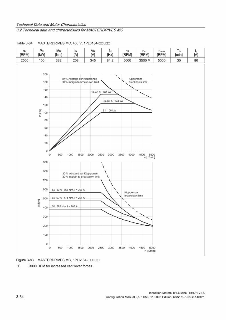
Technical Data and Motor Characteristics 3.2 Technical data and characteristics for MASTERDRIVES MC
Table 3-84 MASTERDRIVES MC, 400 V, 1PL6184-L
nN [RPM]
PN [kW]
MN [Nm]
IN [A]
VN [V]
fN [Hz]
n1 [RPM]
ns1 [RPM]
nmax Tth [min]
Iμ [A]
2500 100 382 208 345 84.2 5000 3500 1) 5000 30 80
[RPM]
F igure 3-8 MASTERDRIVES MC, 1PL6184-L 3
1) 3000 RPM for increased cantilever forces
Induction Motors 1PL6 MASTERDRIVES 3-84 Configuration Manual, (APL6M), 11.2005 Edition, 6SN1197-0AC67-0BP1

Technical Data and Motor Characteristics 3.2 Technical data and characteristics for MASTERDRIVES MC
Table 3-85 MASTERDRIVES MC, 400 V, 1PL6186-L
nN [RPM]
P[kW]
N MN [Nm]
IN [A]
VN [V]
fN [Hz]
n1 [RPM]
ns1 [RPM]
nmax
Tth [min]
Iμ [A]
2500 130 497 275 340 84.1 5000 3500 1) 5000 30 113
[RPM]
F igure 3-8 MASTERDRIVES MC, 1PL6186-L 4
3000 RPM for increased cantilever forces 1)
Induction Motors 1PL6 MASTERDRIVES Configuration Manual, (APL6M), 11.2005 Edition, 6SN1197-0AC67-0BP1 3-85 Siemens Drives & PLCs

Technical Data and Motor Characteristics 3.2 Technical data and characteristics for MASTERDRIVES MC
Table 3-86 MASTERDRIVES MC, 400 V, 1PL6224-L
nN [RPM]
PN [kW]
MN [Nm]
IN [A]
VN [V]
fN [Hz]
n1 [RPM]
ns1 [RPM]
nmax Tth [min]
Iμ [A]
2500 178 680 358 345 84.1 3500 3100 1) 4500 30 119
[RPM]
F igure 3-8 MASTERDRIVES MC, 1PL6224-L 5
1) 2700 RPM for increased cantilever forces
Induction Motors 1PL6 MASTERDRIVES 3-86 Configuration Manual, (APL6M), 11.2005 Edition, 6SN1197-0AC67-0BP1

Technical Data and Motor Characteristics 3.2 Technical data and characteristics for MASTERDRIVES MC
Table 3-87 MASTERDRIVES MC, 400 V, 1PL6226-L
nN [RPM]
PN [kW]
MN [Nm]
IN [A]
VN [V]
fN [Hz]
n1 [RPM]
ns1 [RPM]
nmax
Tth [min]
Iμ [A]
2500 235 898 476 340 84 3500 3100 1) 4500 30 157
[RPM]
0
50
100
150
200
250
300
350
400
450
500
0 500 1000 1500 2000 2500 3000 3500 4000 4500
0
200
400
600
800
1000
1200
1400
1600
0 500 1000 1500 2000 2500 3000 3500 4000 4500
Figure 3-86 MASTERDRIVES MC, 1PL6226-L 1) 2700 RPM for increased cantilever forces
Induction Motors 1PL6 MASTERDRIVES Configuration Manual, (APL6M), 11.2005 Edition, 6SN1197-0AC67-0BP1 3-87 Siemens Drives & PLCs

Technical Data and Motor Characteristics 3.2 Technical data and characteristics for MASTERDRIVES MC
Table 3-88 MASTERDRIVES MC, 400 V, 1PL6228-L
nN [RPM]
PN [kW]
MN [Nm]
IN [A]
VN [V]
fN [Hz]
n1 [RPM]
ns1 [RPM]
nmax Tth [min]
Iμ [A]
2500 265 1013 535 345 84 3500 3100 1) 4500 2) 30 189
[RPM]
F igure 3-8 MASTERDRIVES MC, 1PL6228-L 7
1) 2500 RPM for increased cantilever forces 2) 4000 RPM for increased cantilever forces
Induction Motors 1PL6 MASTERDRIVES 3-88 Configuration Manual, (APL6M), 11.2005 Edition, 6SN1197-0AC67-0BP1

Technical Data and Motor Characteristics 3.2 Technical data and characteristics for MASTERDRIVES MC
3.2.2 P/n diagrams for 3-ph. 480 V AC
Table 3-89 MASTERDRIVES MC, 480 V, 1PL6184-B
nN [RPM]
PN [kW]
MN [Nm]
IN [A]
VN [V]
fN [Hz]
n1 [RPM]
ns1 [RPM]
nmax
Tth [min]
Iμ [A]
24.5 585 69 300 14.4 800 800 800 30 33
[RPM]
400
Figure 3-88 MASTERDRIVES VC, 1PL6184-B
Induction Motors 1PL6 MASTERDRIVES Configuration Manual, (APL6M), 11.2005 Edition, 6SN1197-0AC67-0BP1 3-89 Siemens Drives & PLCs

Technical Data and Motor Characteristics 3.2 Technical data and characteristics for MASTERDRIVES MC
Table 3-90 MASTERDRIVES MC, 480 V, 1PL6186-B
nN [RPM]
PN [kW]
MN [Nm]
IN [A]
VN [V]
fN [Hz]
n1 [RPM]
ns1 [RPM]
nmax Tth [min]
Iμ [A]
400 31.5 752 90 290 14.3 800 800 800 30 47
[RPM]
Figure 3-89 MASTERDRIVES MC, 1PL6186-B
Induction Motors 1PL6 MASTERDRIVES 3-90 Configuration Manual, (APL6M), 11.2005 Edition, 6SN1197-0AC67-0BP1

Technical Data and Motor Characteristics 3.2 Technical data and characteristics for MASTERDRIVES MC
Table 3-91 MASTERDRIVES MC, 480 V, 1PL6224-B
nN [RPM]
PN [kW]
MN [Hz]
[Nm]
IN [A]
VN [V]
fN n1 [RPM]
ns1 [RPM]
nmax
Tth [min]
Iμ [A]
400 45 1074 117 300 14.2 800 800 800 30 45
[RPM]
0
10
20
30
40
50
60
70
80
0 500 1000 1500 2000 2500 3000 3500 4000 4500
0
200
400
600
800
1000
1200
1400
1600
0 500 1000 1500 2000 2500 3000 3500 4000 4500
Figure 3-90 MASTERDRIVES MC, 1PL6224-B
Induction Motors 1PL6 MASTERDRIVES Configuration Manual, (APL6M), 11.2005 Edition, 6SN1197-0AC67-0BP1 3-91 Siemens Drives & PLCs

Technical Data and Motor Characteristics 3.2 Technical data and characteristics for MASTERDRIVES MC
Table 3-92 MASTERDRIVES MC, 480 V, 1PL6226-B
nN [RPM]
PN [kW]
MN n[RPM]
[Nm]
IN [A]
VN [V]
fN [Hz]
n1 [RPM]
s1 nmax Tth [min]
Iμ [A]
400 57 1361 145 305 14.0 800 800 800
[RPM]
30 67
Figure 3-91 MASTERDRIVES MC, 1PL6226-B
Induction Motors 1PL6 MASTERDRIVES 3-92 Configuration Manual, (APL6M), 11.2005 Edition, 6SN1197-0AC67-0BP1
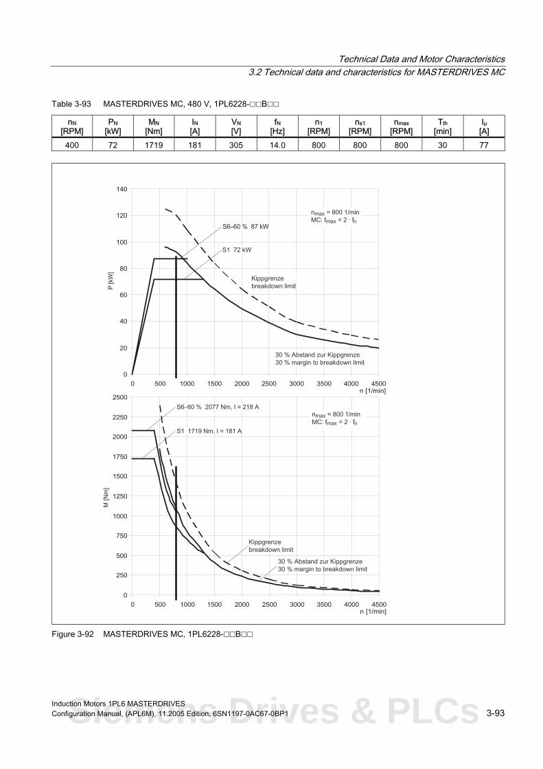
Technical Data and Motor Characteristics 3.2 Technical data and characteristics for MASTERDRIVES MC
Table 3-93 MASTERDRIVES MC, 480 V, 1PL6228-B
nN [RPM]
PN [kW]
MN V[V]
[Nm]
IN [A]
N fN [Hz]
n1 [RPM]
ns1 [RPM]
nmax
Tth [min]
Iμ
400 72 1719 181 305 14.0 800 800 800 30 77
[RPM] [A]
Figure 3-92 MASTERDRIVES MC, 1PL6228-B
Induction Motors 1PL6 MASTERDRIVES Configuration Manual, (APL6M), 11.2005 Edition, 6SN1197-0AC67-0BP1 3-93 Siemens Drives & PLCs

Technical Data and Motor Characteristics 3.2 Technical data and characteristics for MASTERDRIVES MC
Table 3-94 MASTERDRIVES MC, 480 V, 1PL6184-D
nN [RPM]
PN [kW]
MN V[V]
[Nm]
IN [A]
N fN [Hz]
n1 [RPM]
ns1 [RPM]
nmax Tth [min]
Iμ
1150 65 540 121 400 39.4 1750 2300 2300 30 46
[RPM] [A]
Figure 3-93 MASTERDRIVES MC, 1PL6184-D
Induction Motors 1PL6 MASTERDRIVES 3-94 Configuration Manual, (APL6M), 11.2005 Edition, 6SN1197-0AC67-0BP1

Technical Data and Motor Characteristics 3.2 Technical data and characteristics for MASTERDRIVES MC
Table 3-95 MASTERDRIVES MC, 480 V, 1PL6186-D
nN [RPM]
PN [kW]
MN [Nm]
IN [A]
VN [V]
fN [Hz]
n1 [RPM]
ns1 [RPM]
nmax
Tth [min]
Iμ [A]
1150 85 706 158 400 39.4 1950 2300 2300 30 62
[RPM]
Figure 3-94 MASTERDRIVES MC, 1PL6186-D
Induction Motors 1PL6 MASTERDRIVES Configuration Manual, (APL6M), 11.2005 Edition, 6SN1197-0AC67-0BP1 3-95 Siemens Drives & PLCs

Technical Data and Motor Characteristics 3.2 Technical data and characteristics for MASTERDRIVES MC
Table 3-96 MASTERDRIVES MC, 480 V, 1PL6224-D
nN [RPM]
PN [kW]
MN V[V]
[Nm]
IN [A]
N fN [Hz]
n1 [RPM]
ns1 [RPM]
nmax Tth [min]
Iμ [A]
1150 120 997 218 400 39.1 2100 2300 2300 30 86
[RPM]
Figure 3-95 MASTERDRIVES MC, 1PL6224-D
Induction Motors 1PL6 MASTERDRIVES 3-96 Configuration Manual, (APL6M), 11.2005 Edition, 6SN1197-0AC67-0BP1

Technical Data and Motor Characteristics 3.2 Technical data and characteristics for MASTERDRIVES MC
Table 3-97 MASTERDRIVES MC, 480 V, 1PL6226-D
nN [RPM]
PN [kW]
MN [Nm]
IN [A]
VN [V]
fN [Hz]
n1 [RPM]
ns1 [RPM]
nmax
Tth [min]
Iμ [A]
1150 155 1287 275 400 39.2 2000 2300 2300 30 92
[RPM]
Figure 3-96 MASTERDRIVES MC, 1PL6226-D
Induction Motors 1PL6 MASTERDRIVES Configuration Manual, (APL6M), 11.2005 Edition, 6SN1197-0AC67-0BP1 3-97 Siemens Drives & PLCs
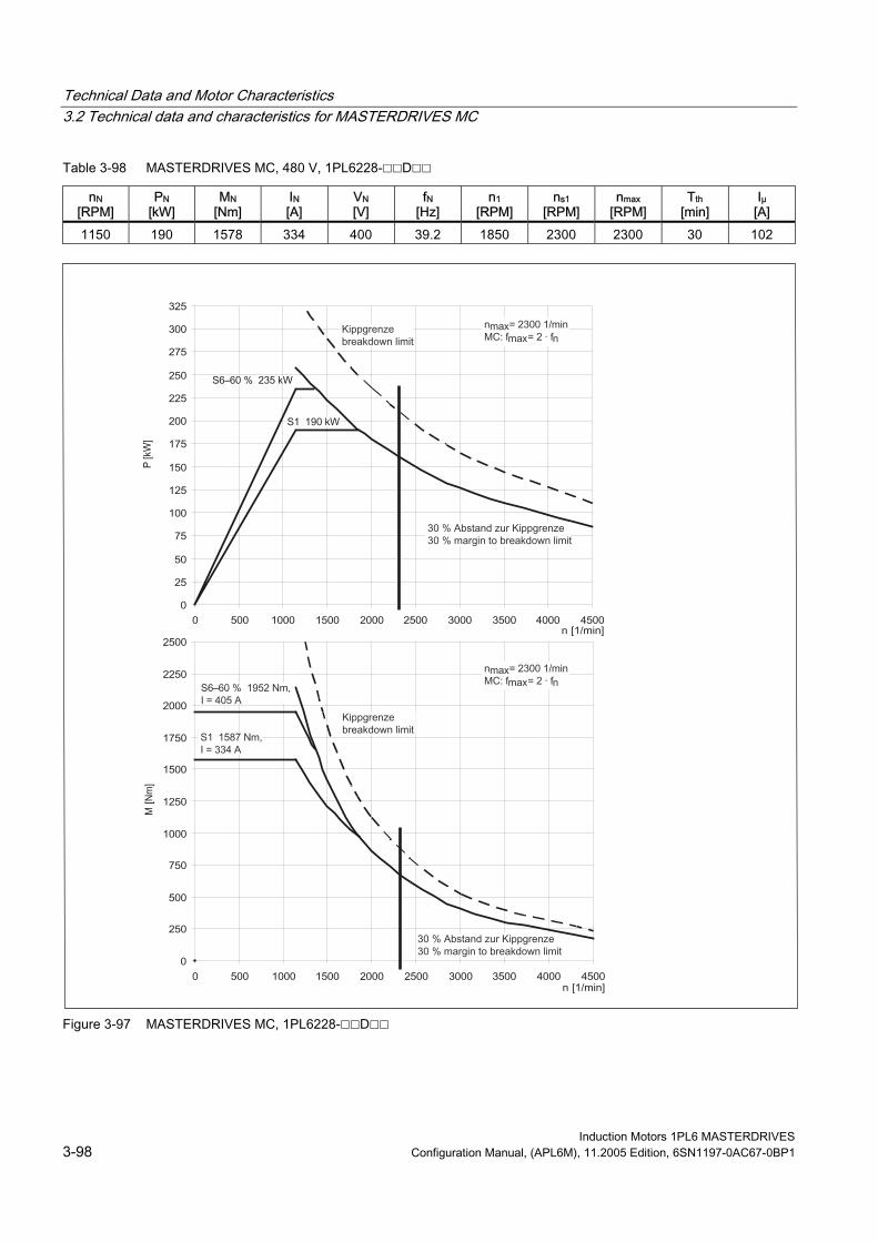
Technical Data and Motor Characteristics 3.2 Technical data and characteristics for MASTERDRIVES MC
Table 3-98 MASTERDRIVES MC, 480 V, 1PL6228-D
nN [RPM]
PN [kW]
MN [Nm]
IN [A]
VN [V]
fN [Hz]
n1 [RPM]
ns1 [RPM]
nmax Tth [min]
Iμ [A]
1150 190 1578 334 400 39.2 1850 2300 2300 30 102
[RPM]
Figure 3-97 MASTERDRIVES MC, 1PL6228-D
Induction Motors 1PL6 MASTERDRIVES 3-98 Configuration Manual, (APL6M), 11.2005 Edition, 6SN1197-0AC67-0BP1

Technical Data and Motor Characteristics 3.2 Technical data and characteristics for MASTERDRIVES MC
Table 3-99 MASTERDRIVES MC, 480 V, 1PL6184-F
nN [RPM]
PN [kW]
MN [Nm]
IN [A]
VN [V]
fN [Hz]
n1 [RPM]
ns1 [RPM]
nmax
Tth [min]
Iμ [A]
1750 89 486 166 400 59.3 3500 3500 1) 3500 30 68
[RPM]
F igure 3-9 MASTERDRIVES MC, 1PL6184-F 8
1) 3000 RPM for increased cantilever forces
Induction Motors 1PL6 MASTERDRIVES Configuration Manual, (APL6M), 11.2005 Edition, 6SN1197-0AC67-0BP1 3-99 Siemens Drives & PLCs

Technical Data and Motor Characteristics 3.2 Technical data and characteristics for MASTERDRIVES MC
Table 3-100 MASTERDRIVES MC, 480 V, 1PL6186-F
nN [RPM]
PN [kW]
MN [Nm]
IN [A]
VN [V]
fN [Hz]
n1 [RPM]
ns1 [RPM]
nmax Tth [min]
Iμ [A]
1750 125 682 231 400 59.3 3400 3500 1) 3500 30 92
[RPM]
Figure 3-99 MASTERDRIVES MC, 1PL6186-F 1) 3000 RPM for increased cantilever forces
Induction Motors 1PL6 MASTERDRIVES 3-100 Configuration Manual, (APL6M), 11.2005 Edition, 6SN1197-0AC67-0BP1

Technical Data and Motor Characteristics 3.2 Technical data and characteristics for MASTERDRIVES MC
Table 3-101 MASTERDRIVES MC, 480 V, 1PL6224-F
nN [RPM]
PN [kW]
MN n[RPM]
[Nm]
IN [A]
VN [V]
fN [Hz]
1 ns1 [RPM]
nmax
Tth [min]
Iμ [A]
1750 165 900 292 400 59.2 3000 3100 1) 3500 30 90
[RPM]
F igure 3-1 MASTERDRIVES MC, 1PL6224-F 00
1) 2700 RPM for increased cantilever forces
Induction Motors 1PL6 MASTERDRIVES Configuration Manual, (APL6M), 11.2005 Edition, 6SN1197-0AC67-0BP1 3-101 Siemens Drives & PLCs

Technical Data and Motor Characteristics 3.2 Technical data and characteristics for MASTERDRIVES MC
Table 3-102 MASTERDRIVES MC, 480 V, 1PL6226-F
nN [RPM]
PN [kW]
MN n[RPM]
[Nm]
IN [A]
VN [V]
fN [Hz]
1 ns1 [RPM]
nmax Tth [min]
Iμ [A]
1750 200 1091 350 400 59.1 2900 3100 1) 3500 30 122
[RPM]
F igure 3-1 MASTERDRIVES MC, 1PL6226-F 01
1) 2700 RPM for increased cantilever forces
Induction Motors 1PL6 MASTERDRIVES 3-102 Configuration Manual, (APL6M), 11.2005 Edition, 6SN1197-0AC67-0BP1

Technical Data and Motor Characteristics 3.2 Technical data and characteristics for MASTERDRIVES MC
Table 3-103 MASTERDRIVES MC, 480 V, 1PL6228-F
nN [RPM]
PN [kW]
MN [Nm]
IN [A]
VN [V]
fN [Hz]
n1 [RPM]
ns1 [RPM]
nmax
Tth [min]
Iμ [A]
1750 265 1446 470 400 59.0 2900 3100 1) 3500 30 174
[RPM]
Figure 3-102 MASTERDRIVES MC, 1PL6228-F 1) 2500 RPM for increased cantilever forces
Induction Motors 1PL6 MASTERDRIVES Configuration Manual, (APL6M), 11.2005 Edition, 6SN1197-0AC67-0BP1 3-103 Siemens Drives & PLCs

Technical Data and Motor Characteristics 3.2 Technical data and characteristics for MASTERDRIVES MC
Table 3-104 MASTERDRIVES MC, 480 V, 1PL6184-L
nN [RPM]
PN [kW]
MN [Nm]
IN [A]
VN [V]
fN [Hz]
n1 [RPM]
ns1 [RPM]
nmax Tth [min]
Iμ [A]
2900 113 372 209 400 97.6 5000 3500 1) 5000 30 79
[RPM]
Figure 3-103 MASTERDRIVES MC, 1PL6184-L 1) 3000 RPM for increased cantilever forces
Induction Motors 1PL6 MASTERDRIVES 3-104 Configuration Manual, (APL6M), 11.2005 Edition, 6SN1197-0AC67-0BP1

Technical Data and Motor Characteristics 3.2 Technical data and characteristics for MASTERDRIVES MC
Table 3-105 MASTERDRIVES MC, 480 V, 1PL6186-L
nN [RPM]
PN [kW]
MN [Hz]
[Nm]
IN [A]
VN [V]
fN n1 [RPM]
ns1 [RPM]
nmax
Tth [min]
Iμ [A]
2900 150 494 280 390 97.5 5000 3500 1) 5000 30 110
[RPM]
Figure 3-104 MASTERDRIVES MC, 1PL6186-L 1) 3000 RPM for increased cantilever forces
Induction Motors 1PL6 MASTERDRIVES Configuration Manual, (APL6M), 11.2005 Edition, 6SN1197-0AC67-0BP1 3-105 Siemens Drives & PLCs

Technical Data and Motor Characteristics 3.2 Technical data and characteristics for MASTERDRIVES MC
Table 3-106 MASTERDRIVES MC, 480 V, 1PL6224-L
nN [RPM]
PN [kW]
MN [Nm]
IN [A]
VN [V]
fN [Hz]
n1 [RPM]
ns1 [RPM]
nmax Tth [min]
Iμ [A]
2900 205 675 365 400 97.5 3500 3100 1) 4500 30 118
[RPM]
Figure 3-105 MASTERDRIVES MC, 1PL6224-L 1) 2700 RPM for increased cantilever forces
Induction Motors 1PL6 MASTERDRIVES 3-106 Configuration Manual, (APL6M), 11.2005 Edition, 6SN1197-0AC67-0BP1

Technical Data and Motor Characteristics 3.2 Technical data and characteristics for MASTERDRIVES MC
Table 3-107 MASTERDRIVES MC, 480 V, 1PL6226-L
nN [RPM]
PN [kW]
MN [Nm]
IN [A]
VN [V]
fN [Hz]
n1 [RPM]
ns1 [RPM]
nmax
Tth [min]
Iμ [A]
2900 270 889 470 400 97.4 3500 3100 1) 4500 30 160
[RPM]
Figure 3-106 MASTERDRIVES MC, 1PL6226-L 1) 2700 RPM for increased cantilever forces
Induction Motors 1PL6 MASTERDRIVES Configuration Manual, (APL6M), 11.2005 Edition, 6SN1197-0AC67-0BP1 3-107 Siemens Drives & PLCs

Technical Data and Motor Characteristics 3.2 Technical data and characteristics for MASTERDRIVES MC
Table 3-108 MASTERDRIVES MC, 480 V, 1PL6228-L
nN [RPM]
PN [kW]
MN [Nm]
IN [A]
VN [V]
fN [Hz]
n1 [RPM]
ns1 [RPM]
nmax Tth [min]
Iμ [A]
2900 300 988 530 400 97.3 3500 3100 1) 4500 2) 30 188
[RPM]
0
50
100
150
200
250
300
350
400
450
500
550
0 500 1000 1500 2000 2500 3000 3500 4000 4500
0
200
400
600
800
1000
1200
1400
1600
1800
2000
0 500 1000 1500 2000 2500 3000 3500 4000 4500
F igure 3-1 MASTERDRIVES MC, 1PL6228-L 07
1) 2500 RPM for increased cantilever forces 2) 4000 RPM for increased cantilever forces
Induction Motors 1PL6 MASTERDRIVES 3-108 Configuration Manual, (APL6M), 11.2005 Edition, 6SN1197-0AC67-0BP1

Technical Data and Motor Characteristics 3.3 Cantilever force/axial force diagrams
3.3 3.3 Cantilever force/axial force diagrams
3.3.1 Cantilever force
Caution When using mechanical transmission elements, which subject the shaft end to a cantilever force, it should be ensured that the maximum limit values, specified in the cantilever force diagrams, are not exceeded.
Note For applications with an extremely low cantilever force load, it should be ensured that the motor shaft is subject to a minimum cantilever force load as specified in the diagrams. Lower cantilever forces can cause the cylindrical bearings to roll in an undefined fashion. This results in increased bearing wear and higher noise. For these applications, bearing designs for a coupling out-drive should be selected.
The diagrams specify the maximum permissible cantilever forces and the cantilever forces that are required as a minimum.
Induction Motors 1PL6 MASTERDRIVES Configuration Manual, (APL6M), 11.2005 Edition, 6SN1197-0AC67-0BP1 3-109 Siemens Drives & PLCs

Technical Data and Motor Characteristics 3.3 Cantilever force/axial force diagrams
SH 180, permissible cantilever forces for a coupling out-drive
Figure 3-108 Cantilever force diagram, shaft height 180 for coupling out-drive
Induction Motors 1PL6 MASTERDRIVES 3-110 Configuration Manual, (APL6M), 11.2005 Edition, 6SN1197-0AC67-0BP1
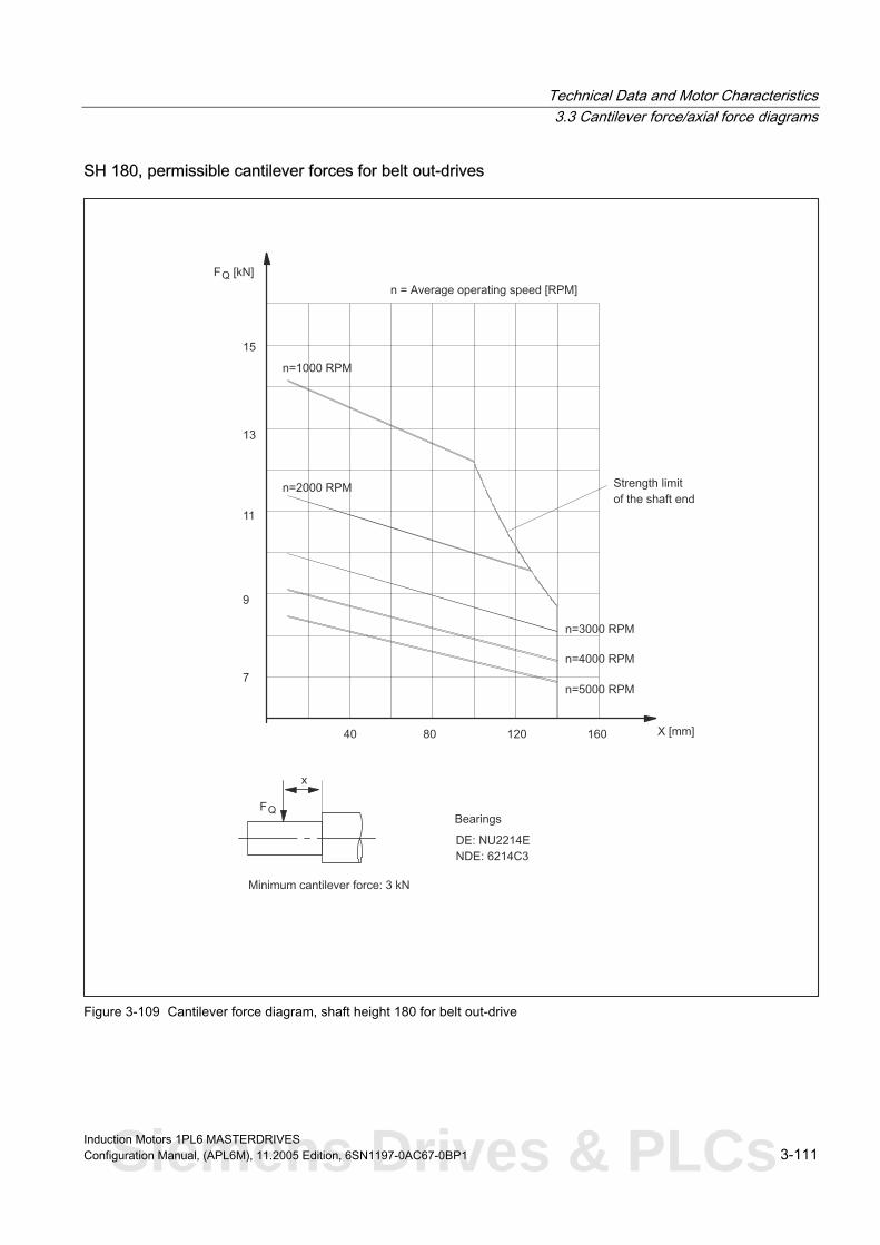
Technical Data and Motor Characteristics 3.3 Cantilever force/axial force diagrams
SH 180, permissible cantilever forces for belt out-drives
Figure 3-109 Cantilever force diagram, shaft height 180 for belt out-drive
Induction Motors 1PL6 MASTERDRIVES Configuration Manual, (APL6M), 11.2005 Edition, 6SN1197-0AC67-0BP1 3-111 Siemens Drives & PLCs

Technical Data and Motor Characteristics 3.3 Cantilever force/axial force diagrams
SH 180, permissible increased cantilever forces for belt out-drives
Figure 3-110 Cantilever force diagram, shaft height 180 for belt out-drives (increased cantilever forces)
Induction Motors 1PL6 MASTERDRIVES 3-112 Configuration Manual, (APL6M), 11.2005 Edition, 6SN1197-0AC67-0BP1

Technical Data and Motor Characteristics 3.3 Cantilever force/axial force diagrams
SH 225, permissible cantilever forces for a coupling out-drive
Figure 3-111 Cantilever force diagram, shaft height 225 for coupling out-drive
Induction Motors 1PL6 MASTERDRIVES Configuration Manual, (APL6M), 11.2005 Edition, 6SN1197-0AC67-0BP1 3-113 Siemens Drives & PLCs

Technical Data and Motor Characteristics 3.3 Cantilever force/axial force diagrams
SH 225, permissible cantilever forces for belt out-drives
Figure 3-112 Cantilever force diagram, shaft height 225 for belt out-drive
Induction Motors 1PL6 MASTERDRIVES 3-114 Configuration Manual, (APL6M), 11.2005 Edition, 6SN1197-0AC67-0BP1

Technical Data and Motor Characteristics 3.3 Cantilever force/axial force diagrams
SH 225, permissible increased cantilever forces for belt out-drives
Figure 3-113 Cantilever force diagram, shaft height 225 for belt out-drives (increased cantilever forces)
Induction Motors 1PL6 MASTERDRIVES Configuration Manual, (APL6M), 11.2005 Edition, 6SN1197-0AC67-0BP1 3-115 Siemens Drives & PLCs

Technical Data and Motor Characteristics 3.3 Cantilever force/axial force diagrams
SH 280, permissible cantilever forces for a coupling out-drive
Figure 3-114 Cantilever force diagram, shaft height 280 for coupling out-drive
Induction Motors 1PL6 MASTERDRIVES 3-116 Configuration Manual, (APL6M), 11.2005 Edition, 6SN1197-0AC67-0BP1

Technical Data and Motor Characteristics 3.3 Cantilever force/axial force diagrams
Induction Motors 1PL6 MASTERDRIVES Configuration Manual, (APL6M), 11.2005 Edition, 6SN1197-0AC67-0BP1 3-117
SH 280, permissible cantilever forces for belt out-drives
Figure 3-115 Cantilever force diagram, shaft height 280 for belt out-drive
Siemens Drives & PLCs

Technical Data and Motor Characteristics 3.3 Cantilever force/axial force diagrams
3.3.2 Axial force For coupling, belt or pinion out-drives with straight teeth, generally, only low axial forces occur. The locating bearing is adequately dimensioned so that these forces can be accepted in all mounting positions.
The following forces due to the weight of the drive-out element are permissible at the shaft end in order to ensure perfect vibration characteristics (i.e. low vibration):
• SH 180: max. 500 N
• SH 225: max. 600 N
• SH 280: max. 900 N
For pinion out-drives with helical gearing, please contact your local Siemens office.
Forces due to the rotor weight
Note The permissible axial force at the shaft end without taking into account the alignment forces, the rotor weight, the mounting position and the force direction.
For information regarding axial forces, refer to the Configuration Manual "General Part for Induction Motors".
Table 3-109 Force due to weight of the rotor and the rotor alignment force
Motor type Force due to weight FL [N] Alignment force FC [N]
1PL6184 980 500 1) 1PL6186 1220 500 1) 1PL6224 1720 550 1) 1PL6226 2100 550 1) 1PL6228 2500 550 1)
600 1) 4000 600 1)
1PL6288 4600
1PL6284 3200 1PL6286
600 1)
1) only for coupling out-drive
Induction Motors 1PL6 MASTERDRIVES 3-118 Configuration Manual, (APL6M), 11.2005 Edition, 6SN1197-0AC67-0BP1

Motor Components 4 4.1 4.1 Thermal motor protection
Table 4-1 Features and technical data
Type KTY 84–130
Connection Via signal cable Response temperature Pre-warning < 145 °C ± 5 °C
Alarm/trip at max. 150 °C ± 5 °C
Resistance when cold (20°C) Approx. 580 Ohm Resistance when hot (100°C) Approx. 1000 Ohm
The resistance change is proportional to the winding temperature change. For 1PL motors, the temperature characteristic is taken into account in the closed-loop control.
For SIMOVERT MASTERDRIVES drive converters, the response temperature for pre-warning and trip can be set using the following parameters:
• MASTERDRIVES VC: P131 = 0 (KTY 84 - 130; factory setting)
• MASTERDRIVES MC: P131 = 1 (KTY 84 - 130; factory setting)
• MASTERDRIVES VC/MC: P380 (pre-warning) and P381 (alarm/trip)
High short-term overload conditions require additional protective measures as a result of the thermal coupling time of the sensor.
The cables for the temperature sensor are included in the pre-fabricated encoder cable.
If the user carries-out an additional high-voltage test, then the ends of the temperature sensor cables must be short-circuited before the test is carried-out! If the test voltage is connected to only one terminal of the temperature sensor, it will be destroyed.
Warning
Warning
There is no adequate protection for thermally critical load situations, e.g. a high overload at motor standstill. In this case, other protective measures must be provided, e.g. a thermal overcurrent relay.
Induction Motors 1PL6 MASTERDRIVES Configuration Manual, (APL6M), 11.2005 Edition, 6SN1197-0AC67-0BP1 4-1 Siemens Drives & PLCs

Motor Components 4.1 Thermal motor protection
[
I
R [kΩ
Figure 4-1 Resistance characteristic as a function of the KTY 84 thermistor temperature
Induction Motors 1PL6 MASTERDRIVES 4-2 Configuration Manual, (APL6M), 11.2005 Edition, 6SN1197-0AC67-0BP1
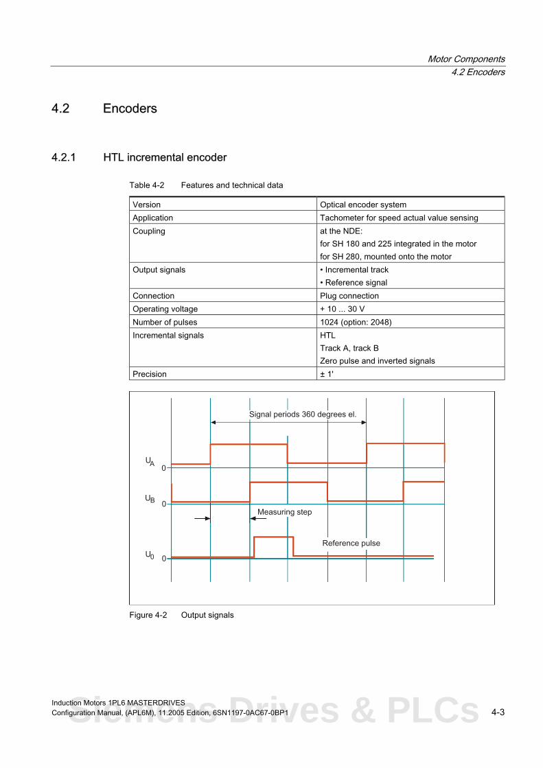
Motor Components 4.2 Encoders
4.2 4.2 Encoders
4.2.1 HTL incremental encoder
Table 4-2 Features and technical data
Version Optical encoder system Application Tachometer for speed actual value sensing Coupling at the NDE:
for SH 180 and 225 integrated in the motor for SH 280, mounted onto the motor
Output signals • Incremental track • Reference signal
Connection Plug connection Operating voltage + 10 ... 30 V Number of pulses 1024 (option: 2048) Incremental signals HTL
Track A, track B Zero pulse and inverted signals
Precision ± 1'
Figure 4-2 Output signals
Induction Motors 1PL6 MASTERDRIVES Configuration Manual, (APL6M), 11.2005 Edition, 6SN1197-0AC67-0BP1 4-3 Siemens Drives & PLCs

Motor Components 4.2 Encoders
Connection
Table 4-3 Connection assignment, 12-pin flange-mounted socket
Signal name PIN Connector type
*B 1
KTY84+ 2
ZERO TRACK 3
*ZERO TRACK 4
A 5
*A 6
B 8
Unassigned 9
10
KTY84- 11
15 V 12
Outer shield at the connector housing
Yes
6FX2003-0CE12
CTRL TACH 7
0 V
Lines
Table 4-4 Pre-fabricated cable for MASTERDRIVES:
6FX 002 - 2AH00 - 0
↓ ↓ 5 MOTION-CONNECT500 8 MOTION-CONNECT800
↓↓↓ Length Max. cable lengths: without transfer of inverted signals,150 m with transfer of inverted signals, 300 m
For other technical data and length code, refer to Catalog, Chapter "MOTION-CONNECT connection system"
Induction Motors 1PL6 MASTERDRIVES 4-4 Configuration Manual, (APL6M), 11.2005 Edition, 6SN1197-0AC67-0BP1

Motor Components 4.2 Encoders
4.2.2 Incremental encoder sin/cos 1 Vpp
Table 4-5 Features and technical data
Version Optical encoder system Application • Tachometer for speed actual value sensing
• Indirect measuring system for the position control loop
Coupling at the NDE: for SH 180 and 225 integrated in the motor for SH 280, mounted onto the motor
Output signals • Incremental track, sinusoidal • One zero pulse (reference mark) per revolution
Connection Plug connection Operating voltage + 5 V ± 5 % Number of pulses 2048 Output signals 1 Vpp Precision ± 40'' Current consumption Max. 150 mA
Figure 4-3 Signal sequence and assignment for a positive direction of rotation (clockwise direction
rotation when viewing the drive end)
Induction Motors 1PL6 MASTERDRIVES Configuration Manual, (APL6M), 11.2005 Edition, 6SN1197-0AC67-0BP1 4-5 Siemens Drives & PLCs

Motor Components 4.2 Encoders
Connection
Table 4-6 Connection assignment, 17-pin flange-mounted socket
Signal name PIN Connector type
Ua1 1
*Ua1 2
Inner shield 17
Ua2 11
*Ua2 12
Inner shield 17
*Ua0 13
Inner shield 17
5
*Ua3 6
Ua4 14
*Ua4 4
+1R1 8
-1R2 9
P encoder 10
5 V sense 16
0 V sense 15
Outer shield at the connector housing
yes
6FX2003-0CE17
Ua0 3
Ua3
M encoder 7
Cables
Table 4-7 Pre-fabricated cable
6FX 002 - 2CA31 - 0
↓ 5 MOTION-CONNECT500 8 MOTION-CONNECT800
↓↓↓ Length Max. cable length 100 m
↓
For other technical data and length code, refer to Catalog, Chapter "MOTION-CONNECT connection system"
Induction Motors 1PL6 MASTERDRIVES 4-6 Configuration Manual, (APL6M), 11.2005 Edition, 6SN1197-0AC67-0BP1

Motor Components 4.2 Encoders
4.2.3 Absolute encoder (EnDat)
Table 4-8 Features and technical data
Version Optical encoder system Application • Tachometer for speed actual value sensing
• Measuring system for the position control loop Coupling at the NDE:
for SH 180 and 225 integrated in the motor for SH 280, mounted onto the motor
Output signals Serial interface Connection Plug connection Operating voltage + 5 V ± 5 % Number of pulses 2048
1 Vpp
Code signals
Output signals Precision ± 40''
Synchronous-serial EnDat interface Binary code, 4096 coded revolutions
Figure 4-4 Output signals, absolute encoders
Induction Motors 1PL6 MASTERDRIVES Configuration Manual, (APL6M), 11.2005 Edition, 6SN1197-0AC67-0BP1 4-7 Siemens Drives & PLCs

Motor Components 4.2 Encoders
Connection
Table 4-9 Connection assignment, 17-pin flange-mounted socket
Signal name PIN Connector type
Ua1 1
*Ua1 2
Ua2 11
*Ua2 12
17
Data 3
*Data 13
17
Clock 5
*Clock cycle 14
8
-1R2
16
5 V sense 16
M encoder 7
15
0 V sense 15
Outer shield at the connector housing
yes
6FX2003-0CE17
Inner shield 17
Inner shield
Inner shield
+1R1
9
P encoder 10
Cables
Table 4-1 Pre-fabricated cable MASTERDRIVES MC 0
6FX 002 - 2EQ10 - 0
↓ ↓
5 MOTION-CONNECT500 8 MOTION-CONNECT800
↓↓↓ Length
Max. cable length 100 m
For other technical data and length code, refer to Catalog, Chapter "MOTION-CONNECT connection system"
Induction Motors 1PL6 MASTERDRIVES 4-8 Configuration Manual, (APL6M), 11.2005 Edition, 6SN1197-0AC67-0BP1

Motor Components 4.2 Encoders
4.2.4 2-pole resolver
Table 4-11 Features and technical data
Version Inductive encoder system Application Tachometer for speed actual value sensing Coupling at the NDE:
for SH 180 and 225 integrated in the motor Output signals Sinusoidal and cosinusoidal tracks Connection Plug connection Operating voltage/frequency + 5 V/4 kHz
Vsinusoidal track = ü ∙ Vexcitation ∙ sin α Vcosine track = ü ∙ Vexcitation ∙ cos α
Angular error width < 14' (2–pole)
Output signals Ratio, ü = 0.5 ± 5 %
Figure 4-5 Resolver output signals
Induction Motors 1PL6 MASTERDRIVES Configuration Manual, (APL6M), 11.2005 Edition, 6SN1197-0AC67-0BP1 4-9 Siemens Drives & PLCs

Motor Components 4.2 Encoders
Connection
Table 4-12 Connection assignment, 12-pin flange-mounted socket
Signal name PIN Connector type
SIN 1
*SIN 2
Inner shield 3
COS 11
*COS 12
Inner shield 5
+1R1 8
-1R2 9
Inner shield 4
+Vpp 10
-Vpp 7
yes
6FX2003-0CE12
Outer shield at the connector housing
Cables
Table 4-1 Pre-fabricated cable MASTERDRIVES MC 3
6FX 002 - 2CF02 - 0
↓ ↓ 5 MOTION-CONNECT500 8 MOTION-CONNECT800
↓↓↓ Length Max. cable length 150 m
For other technical data and length code, refer to Catalog, Chapter "MOTION-CONNECT connection system"
Induction Motors 1PL6 MASTERDRIVES 4-10 Configuration Manual, (APL6M), 11.2005 Edition, 6SN1197-0AC67-0BP1

Dimension Drawings 5
CAD CREATOR
5.1 5.1 Introduction
Note
Using a configuration interface that is very easy to understand, CAD CREATOR allows you to quickly find motor-specific
- technical data
- dimension drawings
- 2D/3D CAD data
and supports you when generating plant/system documentation regarding project-specific information and parts lists.
Internet: http://www.siemens.com/cad-creator
Note Siemens AG reserves the right to change the dimensions of the motors as part of mechanical design improvements without prior notice. This means that dimensions drawings can go out-of-date. Up-to-date dimension drawings can be requested at no charge from your local SIEMENS sales department.
Induction Motors 1PL6 MASTERDRIVES Configuration Manual, (APL6M), 11.2005 Edition, 6SN1197-0AC67-0BP1 5-1 Siemens Drives & PLCs

Dimension Drawings 5.2 Type of construction IM B3 with separately-driven fan
5.2 5.2 Type of construction IM B3 with separately-driven fan
Figure 5-1 1PL6184-B-F,air flow direction DE→NDE, U821027
Induction Motors 1PL6 MASTERDRIVES 5-2 Configuration Manual, (APL6M), 11.2005 Edition, 6SN1197-0AC67-0BP1

Dimension Drawings 5.2 Type of construction IM B3 with separately-driven fan
Figure 5-2 1PL6184-B-F,air flow direction NDE→DE, U821114
Induction Motors 1PL6 MASTERDRIVES Configuration Manual, (APL6M), 11.2005 Edition, 6SN1197-0AC67-0BP1 5-3 Siemens Drives & PLCs

Dimension Drawings 5.2 Type of construction IM B3 with separately-driven fan
Figure 5-3 1PL6184-L, air flow direction DE→NDE, U821029
Induction Motors 1PL6 MASTERDRIVES 5-4 Configuration Manual, (APL6M), 11.2005 Edition, 6SN1197-0AC67-0BP1

Dimension Drawings 5.2 Type of construction IM B3 with separately-driven fan
Figure 5-4 1PL6184-L, air flow direction NDE→DE, U821116
Induction Motors 1PL6 MASTERDRIVES Configuration Manual, (APL6M), 11.2005 Edition, 6SN1197-0AC67-0BP1 5-5 Siemens Drives & PLCs

Dimension Drawings 5.2 Type of construction IM B3 with separately-driven fan
Figure 5-5 1PL6186-B-D, air flow direction DE→NDE, U821031
Induction Motors 1PL6 MASTERDRIVES 5-6 Configuration Manual, (APL6M), 11.2005 Edition, 6SN1197-0AC67-0BP1

Dimension Drawings 5.2 Type of construction IM B3 with separately-driven fan
Figure 5-6 1PL6186-B-D, air flow direction NE→DE, U821118
Induction Motors 1PL6 MASTERDRIVES Configuration Manual, (APL6M), 11.2005 Edition, 6SN1197-0AC67-0BP1 5-7 Siemens Drives & PLCs

Dimension Drawings 5.2 Type of construction IM B3 with separately-driven fan
Figure 5-7 1PL6186-F, air flow direction DE→NDE, U821033
Induction Motors 1PL6 MASTERDRIVES 5-8 Configuration Manual, (APL6M), 11.2005 Edition, 6SN1197-0AC67-0BP1

Dimension Drawings 5.2 Type of construction IM B3 with separately-driven fan
Figure 5-8 1PL6186-F, air flow direction NE→DE, U821120
Induction Motors 1PL6 MASTERDRIVES Configuration Manual, (APL6M), 11.2005 Edition, 6SN1197-0AC67-0BP1 5-9 Siemens Drives & PLCs

Dimension Drawings 5.2 Type of construction IM B3 with separately-driven fan
Figure 5-9 1PL6186-L, air flow direction DE→NDE, U821035
Induction Motors 1PL6 MASTERDRIVES 5-10 Configuration Manual, (APL6M), 11.2005 Edition, 6SN1197-0AC67-0BP1

Dimension Drawings 5.2 Type of construction IM B3 with separately-driven fan
Figure 5-10 1PL6186-L, air flow direction NDE→DE, U821122
Induction Motors 1PL6 MASTERDRIVES Configuration Manual, (APL6M), 11.2005 Edition, 6SN1197-0AC67-0BP1 5-11 Siemens Drives & PLCs

Dimension Drawings 5.2 Type of construction IM B3 with separately-driven fan
Figure 5-11 1PL6224-B, air flow direction DE→NDE, A5E00250615A
Induction Motors 1PL6 MASTERDRIVES 5-12 Configuration Manual, (APL6M), 11.2005 Edition, 6SN1197-0AC67-0BP1
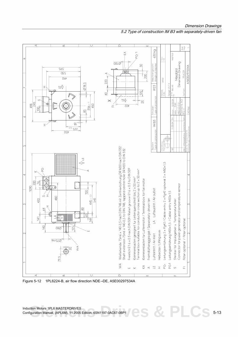
Dimension Drawings 5.2 Type of construction IM B3 with separately-driven fan
Figure 5-12 1PL6224-B, air flow direction NDE→DE, A5E00297534A
Induction Motors 1PL6 MASTERDRIVES Configuration Manual, (APL6M), 11.2005 Edition, 6SN1197-0AC67-0BP1 5-13 Siemens Drives & PLCs

Dimension Drawings 5.2 Type of construction IM B3 with separately-driven fan
Figure 5-13 1PL6224-D, air flow direction DE→NDE, A5E00250626A
Induction Motors 1PL6 MASTERDRIVES 5-14 Configuration Manual, (APL6M), 11.2005 Edition, 6SN1197-0AC67-0BP1

Dimension Drawings 5.2 Type of construction IM B3 with separately-driven fan
Figure 5-14 1PL6224-D, air flow direction NDE→DE, A5E00304428A
Induction Motors 1PL6 MASTERDRIVES Configuration Manual, (APL6M), 11.2005 Edition, 6SN1197-0AC67-0BP1 5-15 Siemens Drives & PLCs

Dimension Drawings 5.2 Type of construction IM B3 with separately-driven fan
Figure 5-15 1PL6224-F-L, air flow direction DE→NDE, A5E00250633A
Induction Motors 1PL6 MASTERDRIVES 5-16 Configuration Manual, (APL6M), 11.2005 Edition, 6SN1197-0AC67-0BP1
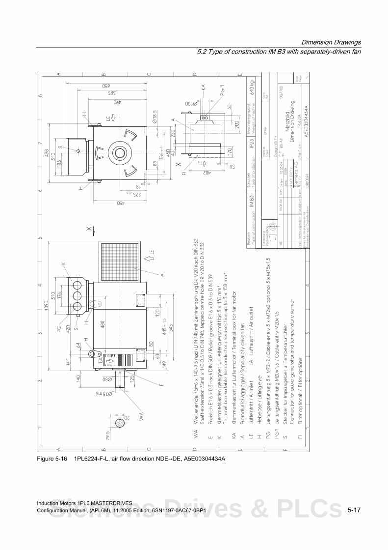
Dimension Drawings 5.2 Type of construction IM B3 with separately-driven fan
Figure 5-16 1PL6224-F-L, air flow direction NDE→DE, A5E00304434A
Induction Motors 1PL6 MASTERDRIVES Configuration Manual, (APL6M), 11.2005 Edition, 6SN1197-0AC67-0BP1 5-17 Siemens Drives & PLCs

Dimension Drawings 5.2 Type of construction IM B3 with separately-driven fan
Figure 5-17 1PL6226-B, air flow direction DE→NDE, A5E00250639A
Induction Motors 1PL6 MASTERDRIVES 5-18 Configuration Manual, (APL6M), 11.2005 Edition, 6SN1197-0AC67-0BP1

Dimension Drawings 5.2 Type of construction IM B3 with separately-driven fan
Figure 5-18 1PL6226-B, air flow direction NDE→DE, A5E00297536A
Induction Motors 1PL6 MASTERDRIVES Configuration Manual, (APL6M), 11.2005 Edition, 6SN1197-0AC67-0BP1 5-19 Siemens Drives & PLCs

Dimension Drawings 5.2 Type of construction IM B3 with separately-driven fan
Figure 5-19 1PL6226-D-L, air flow direction DE→NDE, A5E00250649A
Induction Motors 1PL6 MASTERDRIVES 5-20 Configuration Manual, (APL6M), 11.2005 Edition, 6SN1197-0AC67-0BP1

Dimension Drawings 5.2 Type of construction IM B3 with separately-driven fan
Figure 5-20 1PL6226-D-L, air flow direction NDE→DE, A5E00304449A
Induction Motors 1PL6 MASTERDRIVES Configuration Manual, (APL6M), 11.2005 Edition, 6SN1197-0AC67-0BP1 5-21 Siemens Drives & PLCs
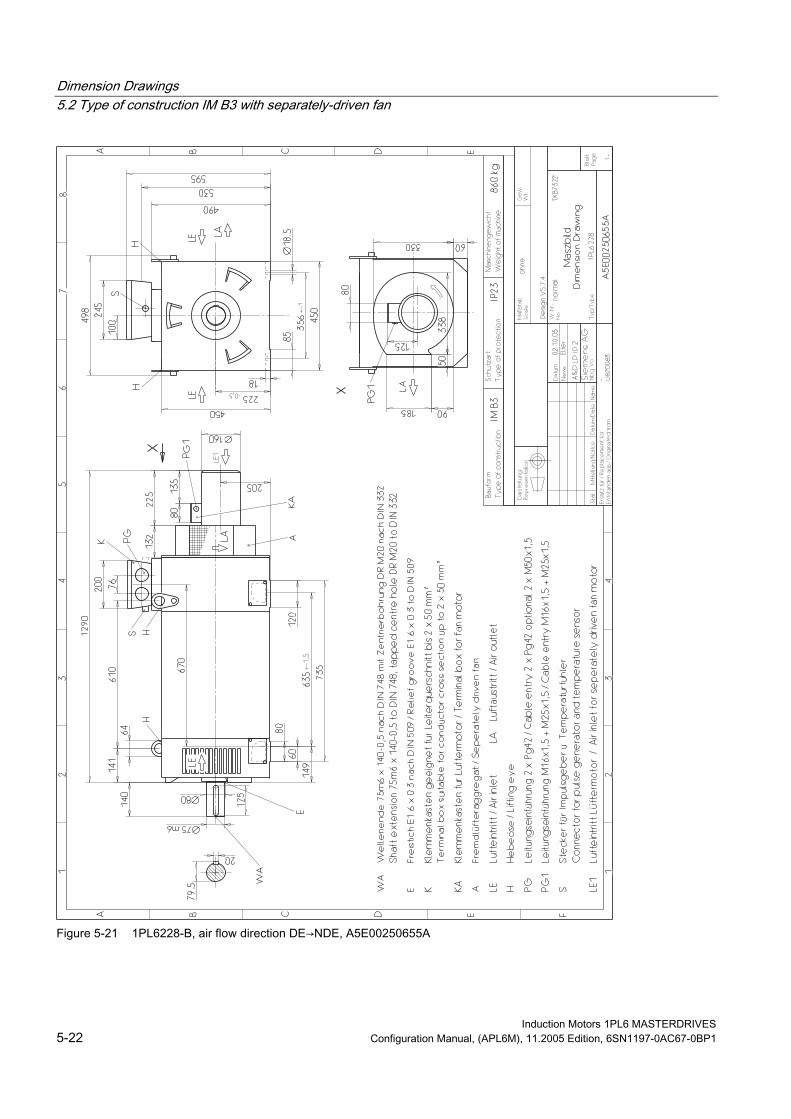
Dimension Drawings 5.2 Type of construction IM B3 with separately-driven fan
Figure 5-21 1PL6228-B, air flow direction DE→NDE, A5E00250655A
Induction Motors 1PL6 MASTERDRIVES 5-22 Configuration Manual, (APL6M), 11.2005 Edition, 6SN1197-0AC67-0BP1

Dimension Drawings 5.2 Type of construction IM B3 with separately-driven fan
Figure 5-22 1PL6228-B, air flow direction NDE→DE, A5E00297537A
Induction Motors 1PL6 MASTERDRIVES Configuration Manual, (APL6M), 11.2005 Edition, 6SN1197-0AC67-0BP1 5-23 Siemens Drives & PLCs
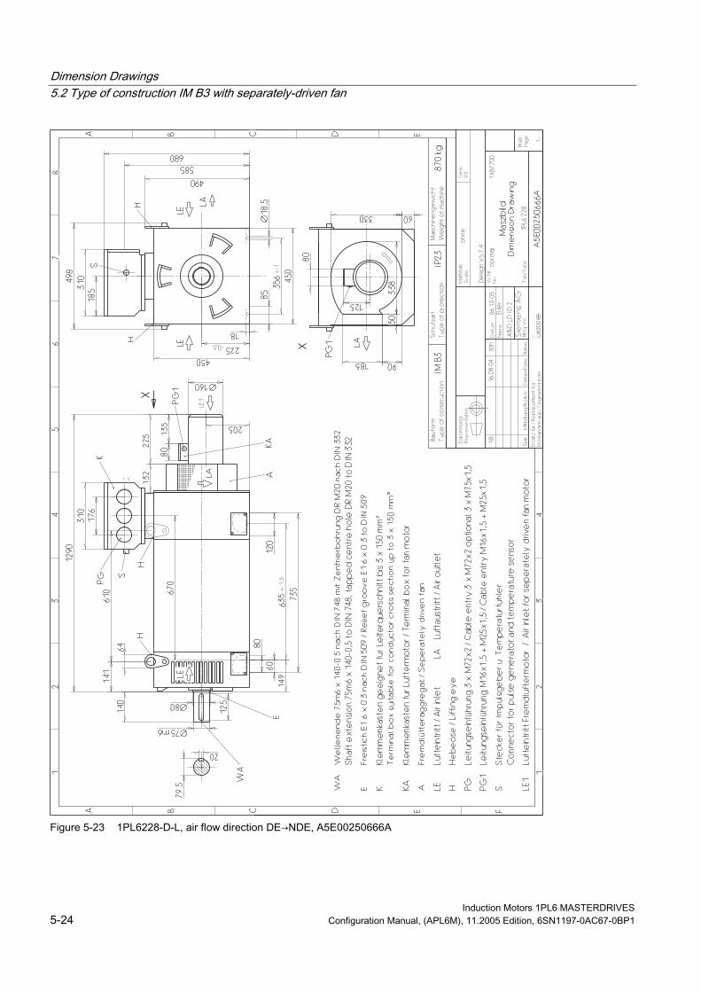
Dimension Drawings 5.2 Type of construction IM B3 with separately-driven fan
Figure 5-23 1PL6228-D-L, air flow direction DE→NDE, A5E00250666A
Induction Motors 1PL6 MASTERDRIVES 5-24 Configuration Manual, (APL6M), 11.2005 Edition, 6SN1197-0AC67-0BP1
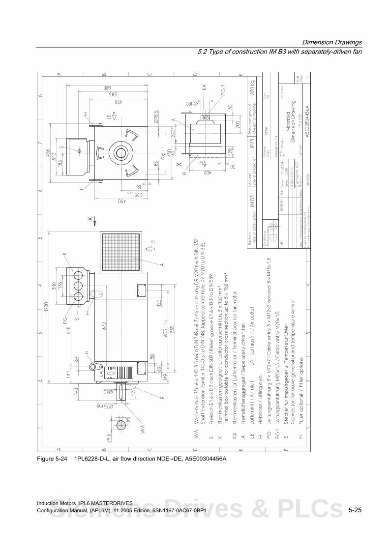
Dimension Drawings 5.2 Type of construction IM B3 with separately-driven fan
Figure 5-24 1PL6228-D-L, air flow direction NDE→DE, A5E00304456A
Induction Motors 1PL6 MASTERDRIVES Configuration Manual, (APL6M), 11.2005 Edition, 6SN1197-0AC67-0BP1 5-25 Siemens Drives & PLCs

Dimension Drawings 5.2 Type of construction IM B3 with separately-driven fan
Figure 5-25 1PL6224-F-L, air flow direction NDE→DE radial, A5E00399100A
Induction Motors 1PL6 MASTERDRIVES 5-26 Configuration Manual, (APL6M), 11.2005 Edition, 6SN1197-0AC67-0BP1

Dimension Drawings 5.2 Type of construction IM B3 with separately-driven fan
Figure 5-26 1PL6226-D-L, air flow direction NDE→DE radial, A5E00399101A
Induction Motors 1PL6 MASTERDRIVES Configuration Manual, (APL6M), 11.2005 Edition, 6SN1197-0AC67-0BP1 5-27 Siemens Drives & PLCs

Dimension Drawings 5.2 Type of construction IM B3 with separately-driven fan
Figure 5-27 1PL6228-D-L, air flow direction NDE→DE radial, A5E00399102A
Induction Motors 1PL6 MASTERDRIVES 5-28 Configuration Manual, (APL6M), 11.2005 Edition, 6SN1197-0AC67-0BP1

Dimension Drawings 5.2 Type of construction IM B3 with separately-driven fan
Figure 5-28 1PL6284, air flow direction NDE→DE, U820928
Induction Motors 1PL6 MASTERDRIVES Configuration Manual, (APL6M), 11.2005 Edition, 6SN1197-0AC67-0BP1 5-29 Siemens Drives & PLCs

Dimension Drawings 5.2 Type of construction IM B3 with separately-driven fan
Figure 5-29 1PL6284, air flow direction NDE→DE, filter, U820930
Induction Motors 1PL6 MASTERDRIVES 5-30 Configuration Manual, (APL6M), 11.2005 Edition, 6SN1197-0AC67-0BP1

Dimension Drawings 5.2 Type of construction IM B3 with separately-driven fan
Figure 5-30 1PL6286, air flow direction NDE→DE, U820940
Induction Motors 1PL6 MASTERDRIVES Configuration Manual, (APL6M), 11.2005 Edition, 6SN1197-0AC67-0BP1 5-31 Siemens Drives & PLCs

Dimension Drawings 5.2 Type of construction IM B3 with separately-driven fan
Figure 5-31 1PL6286, air flow direction NDE→DE, filter, U820942
Induction Motors 1PL6 MASTERDRIVES 5-32 Configuration Manual, (APL6M), 11.2005 Edition, 6SN1197-0AC67-0BP1

Dimension Drawings 5.2 Type of construction IM B3 with separately-driven fan
Figure 5-32 1PL6288, air flow direction NDE→DE, U820952
Induction Motors 1PL6 MASTERDRIVES Configuration Manual, (APL6M), 11.2005 Edition, 6SN1197-0AC67-0BP1 5-33 Siemens Drives & PLCs

Dimension Drawings 5.2 Type of construction IM B3 with separately-driven fan
Figure 5-33 1PL6288, air flow direction NDE→DE, filter, U820954
Induction Motors 1PL6 MASTERDRIVES 5-34 Configuration Manual, (APL6M), 11.2005 Edition, 6SN1197-0AC67-0BP1

Dimension Drawings 5.3 Type of construction IM B3 with second shaft end (SH 280)
5.3 5.3 Type of construction IM B3 with second shaft end (SH 280)
Figure 5-34 1PL6284, air flow direction NDE→DE, filter, U820929
Induction Motors 1PL6 MASTERDRIVES Configuration Manual, (APL6M), 11.2005 Edition, 6SN1197-0AC67-0BP1 5-35 Siemens Drives & PLCs

Dimension Drawings 5.3 Type of construction IM B3 with second shaft end (SH 280)
Figure 5-35 1PL6284, air flow direction NDE→DE, U820927
Induction Motors 1PL6 MASTERDRIVES 5-36 Configuration Manual, (APL6M), 11.2005 Edition, 6SN1197-0AC67-0BP1
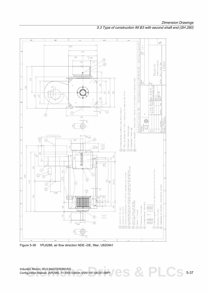
Dimension Drawings 5.3 Type of construction IM B3 with second shaft end (SH 280)
Figure 5-36 1PL6286, air flow direction NDE→DE, filter, U820941
Induction Motors 1PL6 MASTERDRIVES Configuration Manual, (APL6M), 11.2005 Edition, 6SN1197-0AC67-0BP1 5-37 Siemens Drives & PLCs

Dimension Drawings 5.3 Type of construction IM B3 with second shaft end (SH 280)
Figure 5-37 1PL6286, air flow direction NDE→DE, U820939
Induction Motors 1PL6 MASTERDRIVES 5-38 Configuration Manual, (APL6M), 11.2005 Edition, 6SN1197-0AC67-0BP1

Dimension Drawings 5.3 Type of construction IM B3 with second shaft end (SH 280)
Figure 5-38 1PL6288, air flow direction NDE→DE, filter, U820953
Induction Motors 1PL6 MASTERDRIVES Configuration Manual, (APL6M), 11.2005 Edition, 6SN1197-0AC67-0BP1 5-39 Siemens Drives & PLCs

Dimension Drawings 5.3 Type of construction IM B3 with second shaft end (SH 280)
Figure 5-39 1PL6288, air flow direction NDE→DE, U820951
Induction Motors 1PL6 MASTERDRIVES 5-40 Configuration Manual, (APL6M), 11.2005 Edition, 6SN1197-0AC67-0BP1

Dimension Drawings 5.4 Type of construction IM B35 with separately-driven fan
5.4 5.4 Type of construction IM B35 with separately-driven fan
Figure 5-40 1PL6184-B-F, air flow direction DE→NDE, U821028
Induction Motors 1PL6 MASTERDRIVES Configuration Manual, (APL6M), 11.2005 Edition, 6SN1197-0AC67-0BP1 5-41 Siemens Drives & PLCs

Dimension Drawings 5.4 Type of construction IM B35 with separately-driven fan
Figure 5-41 1PL6184-B-F, air flow direction NDE→DE, U821115
Induction Motors 1PL6 MASTERDRIVES 5-42 Configuration Manual, (APL6M), 11.2005 Edition, 6SN1197-0AC67-0BP1

Dimension Drawings 5.4 Type of construction IM B35 with separately-driven fan
Figure 5-42 1PL6184-L, air flow direction DE→NDE, U821030
Induction Motors 1PL6 MASTERDRIVES Configuration Manual, (APL6M), 11.2005 Edition, 6SN1197-0AC67-0BP1 5-43 Siemens Drives & PLCs

Dimension Drawings 5.4 Type of construction IM B35 with separately-driven fan
Figure 5-43 1PL6184-L, air flow direction NDE→DE, U821117
Induction Motors 1PL6 MASTERDRIVES 5-44 Configuration Manual, (APL6M), 11.2005 Edition, 6SN1197-0AC67-0BP1

Dimension Drawings 5.4 Type of construction IM B35 with separately-driven fan
Figure 5-44 1PL6186-B-D, air flow direction DE→NDE, U821032
Induction Motors 1PL6 MASTERDRIVES Configuration Manual, (APL6M), 11.2005 Edition, 6SN1197-0AC67-0BP1 5-45 Siemens Drives & PLCs

Dimension Drawings 5.4 Type of construction IM B35 with separately-driven fan
Figure 5-45 1PL6186-B-D, air flow direction NDE→DE, U821119
Induction Motors 1PL6 MASTERDRIVES 5-46 Configuration Manual, (APL6M), 11.2005 Edition, 6SN1197-0AC67-0BP1

Dimension Drawings 5.4 Type of construction IM B35 with separately-driven fan
Figure 5-46 1PL6186-F, air flow direction DE→NDE, U821034
Induction Motors 1PL6 MASTERDRIVES Configuration Manual, (APL6M), 11.2005 Edition, 6SN1197-0AC67-0BP1 5-47 Siemens Drives & PLCs

Dimension Drawings 5.4 Type of construction IM B35 with separately-driven fan
Figure 5-47 1PL6186-F, air flow direction NDE→DE, U821121
Induction Motors 1PL6 MASTERDRIVES 5-48 Configuration Manual, (APL6M), 11.2005 Edition, 6SN1197-0AC67-0BP1

Dimension Drawings 5.4 Type of construction IM B35 with separately-driven fan
Figure 5-48 1PL6186-L, air flow direction DE→NDE, U821036
Induction Motors 1PL6 MASTERDRIVES Configuration Manual, (APL6M), 11.2005 Edition, 6SN1197-0AC67-0BP1 5-49 Siemens Drives & PLCs

Dimension Drawings 5.4 Type of construction IM B35 with separately-driven fan
Figure 5-49 1PL6186-L, air flow direction NDE→DE, U821123
Induction Motors 1PL6 MASTERDRIVES 5-50 Configuration Manual, (APL6M), 11.2005 Edition, 6SN1197-0AC67-0BP1

Dimension Drawings 5.4 Type of construction IM B35 with separately-driven fan
Figure 5-50 1PL6224-B, air flow direction DE→NDE, A5E00250620A
Induction Motors 1PL6 MASTERDRIVES Configuration Manual, (APL6M), 11.2005 Edition, 6SN1197-0AC67-0BP1 5-51 Siemens Drives & PLCs

Dimension Drawings 5.4 Type of construction IM B35 with separately-driven fan
Figure 5-51 1PL6224-B, air flow direction NDE→DE, A5E00304426A
Induction Motors 1PL6 MASTERDRIVES 5-52 Configuration Manual, (APL6M), 11.2005 Edition, 6SN1197-0AC67-0BP1

Dimension Drawings 5.4 Type of construction IM B35 with separately-driven fan
Figure 5-52 1PL6224-D, air flow direction DE→NDE, A5E00250631A
Induction Motors 1PL6 MASTERDRIVES Configuration Manual, (APL6M), 11.2005 Edition, 6SN1197-0AC67-0BP1 5-53 Siemens Drives & PLCs

Dimension Drawings 5.4 Type of construction IM B35 with separately-driven fan
Figure 5-53 1PL6224-D, air flow direction NDE→DE, A5E00304429A
Induction Motors 1PL6 MASTERDRIVES 5-54 Configuration Manual, (APL6M), 11.2005 Edition, 6SN1197-0AC67-0BP1

Dimension Drawings 5.4 Type of construction IM B35 with separately-driven fan
Figure 5-54 1PL6224-F-L, air flow direction DE→NDE, A5E00250635A
Induction Motors 1PL6 MASTERDRIVES Configuration Manual, (APL6M), 11.2005 Edition, 6SN1197-0AC67-0BP1 5-55 Siemens Drives & PLCs

Dimension Drawings 5.4 Type of construction IM B35 with separately-driven fan
Figure 5-55 1PL6224-F-L, air flow direction NDE→DE, A5E00304435A
Induction Motors 1PL6 MASTERDRIVES 5-56 Configuration Manual, (APL6M), 11.2005 Edition, 6SN1197-0AC67-0BP1

Dimension Drawings 5.4 Type of construction IM B35 with separately-driven fan
Figure 5-56 1PL6226-B, air flow direction DE→NDE, A5E00250643A
Induction Motors 1PL6 MASTERDRIVES Configuration Manual, (APL6M), 11.2005 Edition, 6SN1197-0AC67-0BP1 5-57 Siemens Drives & PLCs

Dimension Drawings 5.4 Type of construction IM B35 with separately-driven fan
Figure 5-57 1PL6226-B, air flow direction NDE→DE, A5E00304436A
Induction Motors 1PL6 MASTERDRIVES 5-58 Configuration Manual, (APL6M), 11.2005 Edition, 6SN1197-0AC67-0BP1

Dimension Drawings 5.4 Type of construction IM B35 with separately-driven fan
Figure 5-58 1PL6226-D-L, air flow direction DE→NDE, A5E00250653A
Induction Motors 1PL6 MASTERDRIVES Configuration Manual, (APL6M), 11.2005 Edition, 6SN1197-0AC67-0BP1 5-59 Siemens Drives & PLCs

Dimension Drawings 5.4 Type of construction IM B35 with separately-driven fan
Figure 5-59 1PL6226-D-L, air flow direction NDE→DE, A5E00304450A
Induction Motors 1PL6 MASTERDRIVES 5-60 Configuration Manual, (APL6M), 11.2005 Edition, 6SN1197-0AC67-0BP1
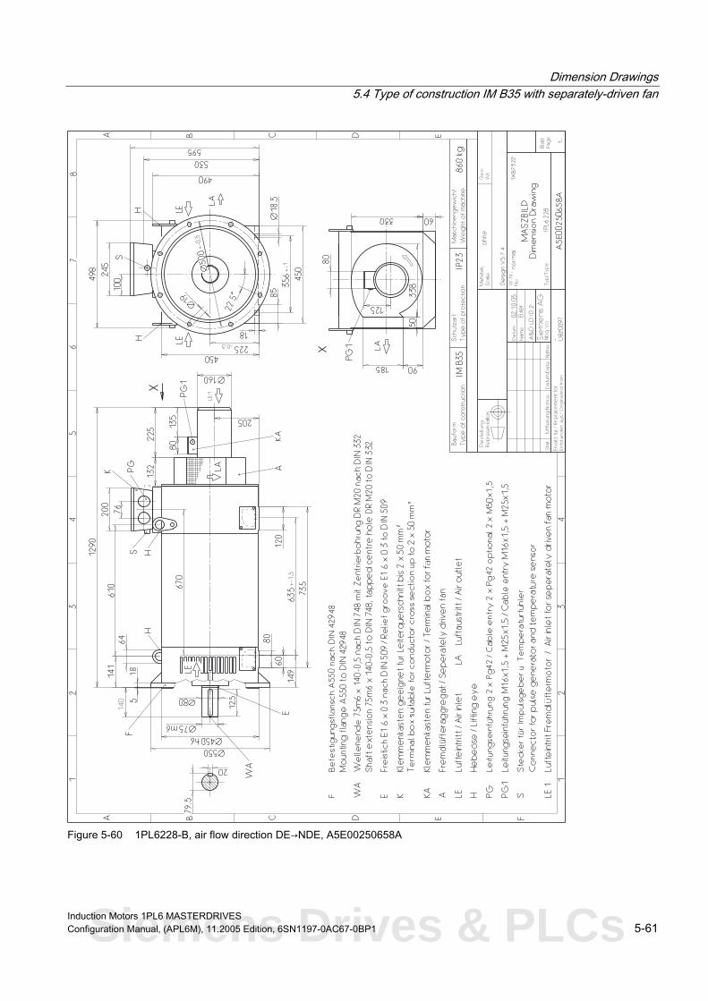
Dimension Drawings 5.4 Type of construction IM B35 with separately-driven fan
Figure 5-60 1PL6228-B, air flow direction DE→NDE, A5E00250658A
Induction Motors 1PL6 MASTERDRIVES Configuration Manual, (APL6M), 11.2005 Edition, 6SN1197-0AC67-0BP1 5-61 Siemens Drives & PLCs

Dimension Drawings 5.4 Type of construction IM B35 with separately-driven fan
Figure 5-61 1PL6228-B, air flow direction NDE→DE, A5E00304452A
Induction Motors 1PL6 MASTERDRIVES 5-62 Configuration Manual, (APL6M), 11.2005 Edition, 6SN1197-0AC67-0BP1

Dimension Drawings 5.4 Type of construction IM B35 with separately-driven fan
Figure 5-62 1PL6228-D-L, air flow direction DE→NDE, A5E00250667A
Induction Motors 1PL6 MASTERDRIVES Configuration Manual, (APL6M), 11.2005 Edition, 6SN1197-0AC67-0BP1 5-63 Siemens Drives & PLCs

Dimension Drawings 5.4 Type of construction IM B35 with separately-driven fan
Figure 5-63 1PL6228-D-L, air flow direction NDE→DE, A5E00304457A
Induction Motors 1PL6 MASTERDRIVES 5-64 Configuration Manual, (APL6M), 11.2005 Edition, 6SN1197-0AC67-0BP1

Dimension Drawings 5.4 Type of construction IM B35 with separately-driven fan
Figure 5-64 1PL6224-F-L, air flow direction NDE→DE radial, A5E00399103A
Induction Motors 1PL6 MASTERDRIVES Configuration Manual, (APL6M), 11.2005 Edition, 6SN1197-0AC67-0BP1 5-65 Siemens Drives & PLCs

Dimension Drawings 5.4 Type of construction IM B35 with separately-driven fan
Figure 5-65 1PL6226-D-L, air flow direction NDE→DE radial, A5E00399104A
Induction Motors 1PL6 MASTERDRIVES 5-66 Configuration Manual, (APL6M), 11.2005 Edition, 6SN1197-0AC67-0BP1

Dimension Drawings 5.4 Type of construction IM B35 with separately-driven fan
Figure 5-66 1PL6228-D-L, air flow direction NDE→DE radial, A5E0399105A
Induction Motors 1PL6 MASTERDRIVES Configuration Manual, (APL6M), 11.2005 Edition, 6SN1197-0AC67-0BP1 5-67 Siemens Drives & PLCs

Dimension Drawings 5.4 Type of construction IM B35 with separately-driven fan
Figure 5-67 1PL6284, air flow direction NDE→DE, U820934
Induction Motors 1PL6 MASTERDRIVES 5-68 Configuration Manual, (APL6M), 11.2005 Edition, 6SN1197-0AC67-0BP1

Dimension Drawings 5.4 Type of construction IM B35 with separately-driven fan
Figure 5-68 1PL6284, air flow direction NDE→DE, filter, U820936
Induction Motors 1PL6 MASTERDRIVES Configuration Manual, (APL6M), 11.2005 Edition, 6SN1197-0AC67-0BP1 5-69 Siemens Drives & PLCs

Dimension Drawings 5.4 Type of construction IM B35 with separately-driven fan
Figure 5-69 1PL6286, air flow direction NDE→DE, U820946
Induction Motors 1PL6 MASTERDRIVES 5-70 Configuration Manual, (APL6M), 11.2005 Edition, 6SN1197-0AC67-0BP1

Dimension Drawings 5.4 Type of construction IM B35 with separately-driven fan
Figure 5-70 1PL6286, air flow direction NDE→DE, filter, U820948
Induction Motors 1PL6 MASTERDRIVES Configuration Manual, (APL6M), 11.2005 Edition, 6SN1197-0AC67-0BP1 5-71 Siemens Drives & PLCs

Dimension Drawings 5.4 Type of construction IM B35 with separately-driven fan
Figure 5-71 1PL6288, air flow direction NDE→DE, U820958
Induction Motors 1PL6 MASTERDRIVES 5-72 Configuration Manual, (APL6M), 11.2005 Edition, 6SN1197-0AC67-0BP1

Dimension Drawings 5.4 Type of construction IM B35 with separately-driven fan
Figure 5-72 1PL6288, air flow direction NDE→DE, filter, U820960
Induction Motors 1PL6 MASTERDRIVES Configuration Manual, (APL6M), 11.2005 Edition, 6SN1197-0AC67-0BP1 5-73 Siemens Drives & PLCs

Dimension Drawings 5.5 Type of construction IM B35 with second shaft end (SH 280)
5.5 5.5 Type of construction IM B35 with second shaft end (SH 280)
Figure 5-73 1PL6284, air flow direction NDE→DE, filter, U820935
Induction Motors 1PL6 MASTERDRIVES 5-74 Configuration Manual, (APL6M), 11.2005 Edition, 6SN1197-0AC67-0BP1

Dimension Drawings 5.5 Type of construction IM B35 with second shaft end (SH 280)
Figure 5-74 1PL6284, air flow direction NDE→DE, U820933
Induction Motors 1PL6 MASTERDRIVES Configuration Manual, (APL6M), 11.2005 Edition, 6SN1197-0AC67-0BP1 5-75 Siemens Drives & PLCs

Dimension Drawings 5.5 Type of construction IM B35 with second shaft end (SH 280)
Figure 5-75 1PL6286, air flow direction NDE→DE, filter, U820947
Induction Motors 1PL6 MASTERDRIVES 5-76 Configuration Manual, (APL6M), 11.2005 Edition, 6SN1197-0AC67-0BP1

Dimension Drawings 5.5 Type of construction IM B35 with second shaft end (SH 280)
Figure 5-76 1PL6286, air flow direction NDE→DE, U820945
Induction Motors 1PL6 MASTERDRIVES Configuration Manual, (APL6M), 11.2005 Edition, 6SN1197-0AC67-0BP1 5-77 Siemens Drives & PLCs

Dimension Drawings 5.5 Type of construction IM B35 with second shaft end (SH 280)
Figure 5-77 1PL6288, air flow direction NDE-DE, filter, U820959
Induction Motors 1PL6 MASTERDRIVES 5-78 Configuration Manual, (APL6M), 11.2005 Edition, 6SN1197-0AC67-0BP1

Dimension Drawings 5.5 Type of construction IM B35 with second shaft end (SH 280)
Figure 5-78 1PL6288, air flow direction NDE-DE, U820957
Induction Motors 1PL6 MASTERDRIVES Configuration Manual, (APL6M), 11.2005 Edition, 6SN1197-0AC67-0BP1 5-79 Siemens Drives & PLCs

Dimension Drawings 5.5 Type of construction IM B35 with second shaft end (SH 280)
Induction Motors 1PL6 MASTERDRIVES 5-80 Configuration Manual, (APL6M), 11.2005 Edition, 6SN1197-0AC67-0BP1

A Appendix A
A.1 A.1 References
An overview of publications that is updated monthly is provided in a number of languages in the Internet at:
<http://www.siemens.com/motioncontrol> through "Support", "Technical Documentation", "Documentation Overview"
General Documentation
/D 21.2/ SINAMICS S120 Catalog SINAMICS S120
e System Servo Control Driv
/D 21.1/ SINAMICS S120 Catalog SINAMICS S120
e System Vector Control Driv
/NC 60/ SINUMERIK and SIMODRIVE Catalog Automation Systems for Machine Tools
/NC 61/ SINUMERIK and SINAMICS Catalog Automation Systems for Machine Tools
/DA65.3/ SIMOVERT MASTERDRIVES Catalog Synchronous and Induction Motors for SIMOVERT MASTERDRIVES
Electronic Documentation
/CD1/ DOC ON CD The SINUMERIK System
(includes all SINUMERIK 840D/810D and SIMODRIVE 611D)
Induction Motors 1PL6 MASTERDRIVES Configuration Manual, (APL6M), 11.2005 Edition, 6SN1197-0AC67-0BP1 A-1 Siemens Drives & PLCs

Appendix A.1 References
/CD2/ DOC ON CD The SINAMICS System
Manufacturer/Service Documentation
/PJAL/ Configuration Manual, Synchronous Motors SIMODRIVE 611, SIMOVERT MASTERDRIVES MC
Synchronous Motors General Section
/PFK7S/ Configuration Manual, Synchronous Motors SINAMICS S120
Motors 1FK7 Synchronous
/PFT6S/ Configuration Manual, Synchronous Motors SINAMICS S120
Motors 1FT6 Synchronous
SIMODRIVE 611, SIMOVERT MASTERDRIVES 1FK7 Synchronous Motors
/PMH2/ Configuration Manual, Hollow-Shaft Measuring System SINAMICS S120, SIMODRIVE 611, SIMOVERT MASTERDRIVES,
SIMAG H2 Hollow-Shaft Measuring System
/PFK7/ Configuration Manual, Synchronous Motors
/PFT6/ Configuration Manual, Synchronous Motors SIMODRIVE 611, SIMOVERT MASTERDRIVES
1FT6 Synchronous Motors
/PFK6/ Configuration Manual, Synchronous Motors SIMODRIVE 611, SIMOVERT MASTERDRIVES
1FK6 Synchronous Motors
Induction Motors 1PL6 MASTERDRIVES A-2 Configuration Manual, (APL6M), 11.2005 Edition, 6SN1197-0AC67-0BP1

Appendix A.1 References
/PFS6/ Configuration Manual, Synchronous Motors SIMOVERT MASTERDRIVES
1FS6 Synchronous Motors, Explosion-Protected
/PFU/ Configuration Manual, Synchronous Motors
/APH2/
SINAMICS S120, SIMOVERT MASTERDRIVES, MICROMASTER SIEMOSYN Synchronous Motors 1FU8
/ASAL/ Configuration Manual, Induction Motors SIMODRIVE 611, SIMOVERT MASTERDRIVES
Induction Motors General Section
Configuration Manual, Induction Motors SIMODRIVE 611
s 1PH2 Induction Motor
/APH4/ Configuration Manual, Induction Motors SIMODRIVE 611
s 1PH4 Induction Motor
/APH7/ Configuration Manual, Induction Motors SIMODRIVE 611
s 1PH7 Induction Motor
/PPM/ Configuration Manual, Hollow-Shaft Motors SIMODRIVE 611
Hollow Shaft Motors for Main Spindle Drives 1PM6 and 1PM4
/PJFE/ Configuration Manual, Synchronous Build-in Motors SIMODRIVE 611
Synchronous Motors for Main Spindle Drives 1FE1 Synchronous Build-in Motors
Induction Motors 1PL6 MASTERDRIVES Configuration Manual, (APL6M), 11.2005 Edition, 6SN1197-0AC67-0BP1 A-3 Siemens Drives & PLCs

Appendix A.1 References
/PJTM/ Configuration Manual, Build-in Torque Motors SIMODRIVE 611
1FW6 Build-in Torque Motors
/PJLM/ Configuration Manual, Linear Motors SIMODRIVE 611
1FN1 and 1FN3 Linear Motors
/PMS/ Configuration Manual, ECO Motor Spindle SIMODRIVE 611
2SP1 ECO Motor Spindle
/APL6/ Configuration Manual, Induction Motors SIMOVERT MASTERDRIVES VC/MC
1PL6 Induction Motors
/APH7M/ Configuration Manual, Induction Motors SIMOVERT MASTERDRIVES VC/MC
1PH7 Induction Motors
/PKTM/ Configuration Manual, Complete Torque Motors SIMOVERT MASTERDRIVES
1FW3 Complete Torque Motors
Induction Motors 1PL6 MASTERDRIVES A-4 Configuration Manual, (APL6M), 11.2005 Edition, 6SN1197-0AC67-0BP1

Index A G Absolute encoder, 4-7 Grounding conductor, 2-3 Applications, 1-2 Axial force, 3-118
H Hotline, iv C HTL incremental encoder, 4-3
Cantilever force, 3-109 Characteristics, 1-2
I Connecting-up information, 2-3 Cooling, 1-23 Incremental encoder sin/cos 1Vpp, 4-5 Cross-sections, 2-2
K D KTY 84, 4-1 Danger and warning information, v
Derating, 1-23 Dimension drawings, 5-1 M IMB3 with separately-driven fan, 5-2 Documentation Motor components, 4-1
Order Nos., iii Mounting instructions, 1-34
E N Electrical connection Natural frequency when mounted, 1-37
Motor, 2-1 NDE bearings, 1-30 Separately-driven fan, 2-7 No-load current, 3-1
Encoders Absolute encoder, 4-7
O HTL incremental encoder, 4-3 Incremental encoder sin/cos, 4-5 Options Resolver 2-pole, 4-9 for SH 180, 225 and 280, 1-5 ESDS instructions, vii for SH 225, 1-6
for SH 280, 1-7
F P Fan mounting, 1-23
Forces due to the rotor weight, 3-118 P/n and M/n characteristics MASTERDRIVES VC 3-ph. 400V AC, 3-2 MASTERDRIVES VC 3-ph. 480V AC, 3-31
Induction Motors 1PL6 MASTERDRIVES Configuration Manual, (APL6M), 11.2005 Edition, 6SN1197-0AC67-0BP1 Index-1 Siemens Drives & PLCs

Index
MASTERDRIVES VC 3-ph. 690V AC, 3-60 P/n characteristics
MASTERDRIVES MC 3-ph. 400V AC, 3-69 MASTERDRIVES MC 3-ph. 480V AC, 3-89
Power connection, 2-1
R Rated current, 3-1 Rated speed, 3-1 Rating plate, 1-22 Resolver, 4-9
S Separately-driven fan, 2-7
T Technical data
MASTERDRIVES MC 3-ph. 400V AC, 3-69 MASTERDRIVES MC 3-ph. 480V AC, 3-89 MASTERDRIVES VC 3-ph. 480V AC, 3-31 MASTERDRIVES VC 3-ph. 690V AC, 3-60
Technical features, 1-3 Technical Support, iv Terminal box, 2-1 Terminal box assignment, 2-3 Thermal motor protection, 4-1
Induction Motors 1PL6 MASTERDRIVES Index-2 Configuration Manual, (APL6M), 11.2005 Edition, 6SN1197-0AC67-0BP1

Suggestions
Corrections
To
SIEMENS AG
A&D MC MS
Postfach 3180
D-91050 Erlangen
Tel.: +49 (0) 180 / 5050 - 222 (Service Support)
Fax: +49 (0) 9131 / 98 – 63315 (Documentation)
mailto:[email protected]
For Publication/Manual:
Induction Motors
1PL6
SIMOVERT MASTERDRIVES VC/MC
Manufacturer/Service Documentation
Configuration Manual
Order No.: 6SN1197-0AC67-0BP1
Edition: 11.2005
From
Name
Company/Department
Address
Postal code: Town:
Telephone: /
Telefax: /
If you come across any printing errors in this
document, please let us know using this form.
We would also be grateful for any suggestions and
recommendations for improvement.
Suggestions and/or corrections
Siemens Drives & PLCs