indirect fired portable heater - smoky … list.....11-16 warning: read the instructions given in...
TRANSCRIPT

OPERATING INSTRUCTIONS AND OWNER’S MANUALREAD INSTRUCTIONS CAREFULLY: Read and follow all instructions. Place instructions in a safe place for future reference. Do not allow anyone who has not read these instructions to assemble, light, adjust or operate the heater.
MO
DEL
MO
DEL
1000ID, 2000ID 3000ID
1000ID, 2000ID 3000ID, 4000ID
06/11 #50120 Rev.AENERCO GROUP, INC., 4560 W. 160TH ST., CLEVELAND, OHIO 44135 • 800-251-0001
INDIRECT FIRED PORTABLE HEATER
HEATSTARBY ENERCOMR. HEATER
If the information in this manual is not followed exactly, afire or explosion may result causing property damage, personal injury or loss of life.
WARNING:
— Do not store or use gasoline or other flammable vapors and liquids in the vicinity of this or any other appliance.
— Service must be performed by a qualified service agency.
This is a vented portable heater. It uses air (oxygen) from the area in which it is used. Adequate combustion air and ventilation must be provided. Refer to page 5.

2ENERCO GROUP, INC. |Indirect Fired Portable Heater Operating Instructions and Owner’s Manual
WARNING: FIRE, BURN, INHALATION, AND EXPLOSION HAZARD. KEEP SOLID COMBUSTIBLES, SUCH AS BUILDING MA-TERIALS, PAPER OR CARDBOARD, A SAFE DISTANCE AWAY FROM THE HEATER AS RECOMMENDED BY THE INSTRUCTIONS NEVER USE THE HEATER IN SPACES WHICH DO OR MAY CONTAIN VOLATILE OR AIRBORNE COMBUSTIBLES, OR PRODUCTS SUCH AS GASOLINE, SOLVENTS, PAINT THINNER, DUST PARTICLES OR UN-KNOWN CHEMICALS.
WARNING: COMBUSTION BY-PRODUCTS PRODUCED WHEN US-ING THIS PRODUCT CONTAIN CARBON MONOXIDE, A CHEMICAL KNOWN TO THE STATE OF CALIFORNIA TO CAUSE CANCER AND BIRTH DEFECTS (OR OTHER REPRODUCTIVE HARM).
GENERAL HAZARD WARNING: FAILURE TO COMPLY WITH THE PRECAUTIONS AND INSTRUCTIONS PROVIDED WITH THIS HEATER, CAN RESULT IN DEATH, SERIOUS BODILY INJURY AND PROPERTY LOSS OR DAMAGE FROM HAZARDS OF FIRE, EXPLOSION, BURN, ASPHYXIATION, CARBON MONOX-IDE POISONING, AND/OR ELECTRICAL SHOCK.
ONLY PERSONS WHO CAN UNDERSTAND AND FOLLOW THE INSTRUCTIONS SHOULD USE OR SERVICE THIS HEATER.
IF YOU NEED ASSISTANCE OR HEATER INFORMATION SUCH AS AN INSTRUCTIONS MANUAL, LABELS, ETC. CONTACT THE MANUFACTURER.
WARNING: NOT FOR HOME OR RECREATIONAL VEHICLE USE
WARNING: YOUR SAFETY IS IMPORTANT TO YOU AND TO OTHERS, SO PLEASE READ THESE INSTRUCTIONS BEFORE YOU OPERATE THIS HEATER.
The State of California requires the following warning:
CONTENTS
WARNINGS .................................................................................. 2
SPECIFICATIONS ........................................................................... 3
OPERATION ................................................................................. 4
SAFETY DEVICES .......................................................................... 4
MAINTENANCE ............................................................................ 5
VENTILATION ............................................................................... 5
TROUBLESHOOTING .................................................................... 6
WIRING DIAGRAMS ..................................................................... 7
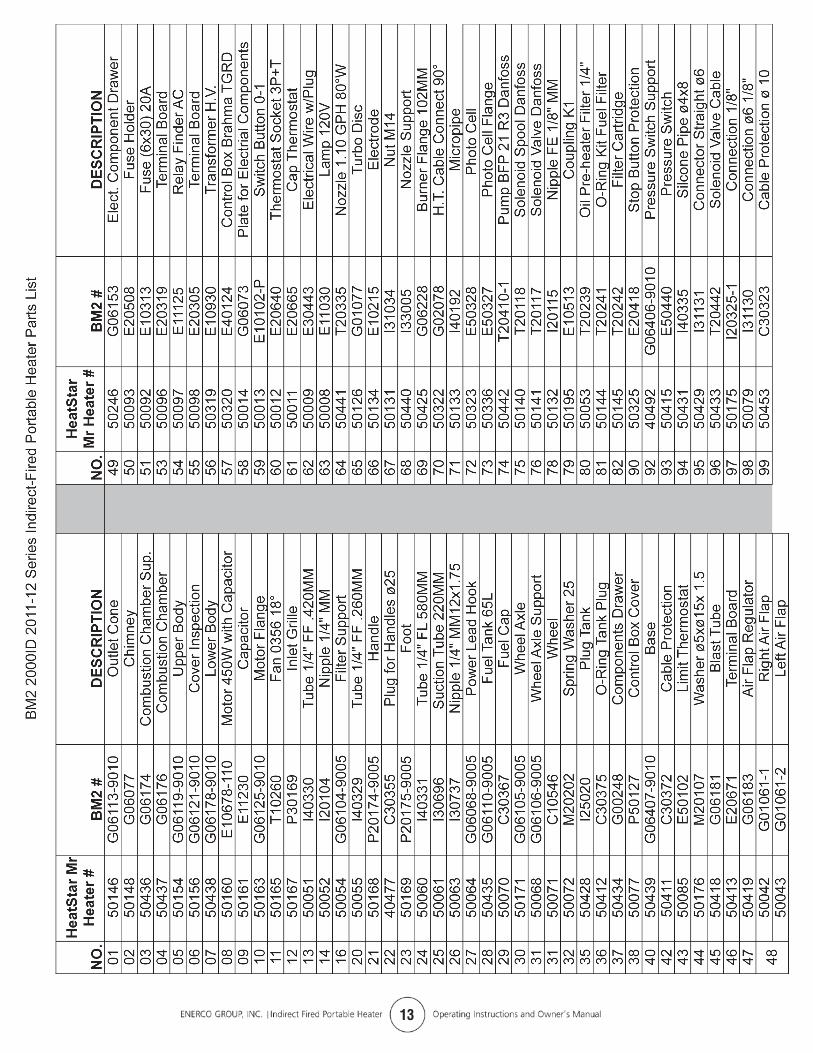
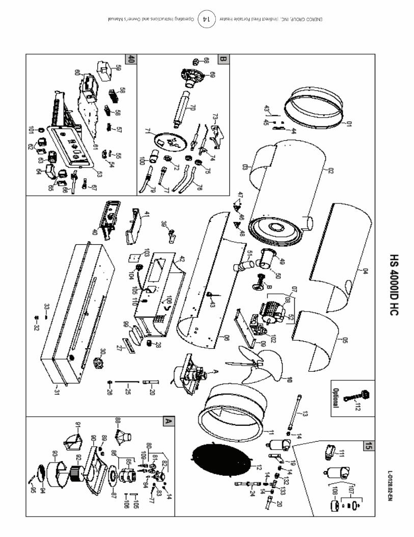
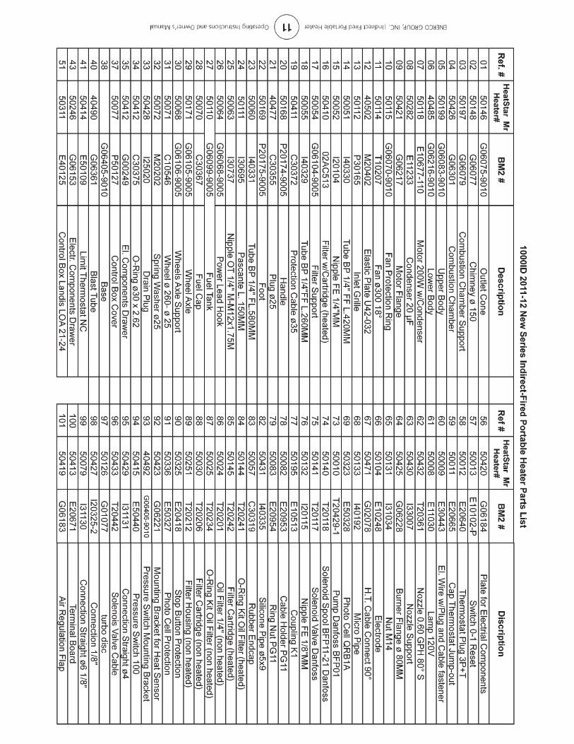
PARTS LIST .............................................................................11-16
WARNING: READ THE INSTRUCTIONS GIVEN IN THIS MANUAL BEFORE USING THE APPLIANCE.
• DO NOT USE GASOLINE, NAPHTHA OR VOLATILE FUELS.
• THE ELECTRICAL SYSTEM TO WHICH THE APPLIANCE IS CONNECTED MUST COMPLY WITH ALL SAFETY REGULATIONS IN FORCE. A RESIDUAL CURRENT CIRCUIT BREAKER MUST BE PROVIDED ON THE MAIN DISTRIBUTION BOARD.
• UNPLUG THE HEATER BEFORE ATTEMPTING ANY SERVICE OR MAINTENANCE.
• ALWAYS CHECK THE POWER SUPPLY CABLE BEFORE USE. IT MUST NOT BE BENT, CRUSHED, OR ANYWAY DAMAGED.
• THE POWER SUPPLY CABLE MUST BE REPLACED ONLY BY QUALIFIED PERSONNEL.
• ONLY USE AN ORIGINAL H07RN-F POWER CABLE WITH WATERPROOF PLUG.
• DO NOT TOUCH THE EXHAUST GAS OUTLET. DANGER OF BURNS!

3 operating Instructions and owner’s ManualeNeRCo GRoUP, INC. |Indirect Fired Portable Heater
tecHnical speciFicatiOnsMH 1000idHs 1000id
MH 2000idHs 2000id
MH 3000idHs 3000id Hs 4000id
Heat input [kBTU/h] 110 205 300 400
Air flow [cfm] 880 1,530 2,500 2,760
Fuel Type Diesel/Kerosene/#1-2 Fuel Oil
Heat output [kBTU/h] 91.9 174.9 254.4 335.6
Fuel consumption[gal/h] 0.80 1.48 2.28 2.82
[lb/h] 5.53 10.35 15.07 20.07
Power supply
Phase 1 1 1 1
Voltage [V] 120 120 120 120
Frequency [Hz] 60 60 60 60
electric consumption[W] 520 785 1.240 1.440
[A] 5.76 8.30 11.40 13.20
Nozzle [USgal/h] 0.60-80° S 1.00-45° W 1.20-45° W 1.50-45° W
Pump pressure [psi] 167P1: 137 P1: 160 P1: 203
P2: 239 P2: 350 P2: 348
Max static pressure [in WC] 0.5 0.5 0.5 0.5
Recommended max. temp. in the air duct
[°F] 250 250 250 250
Adjustment of combustion air flap[in] a=0.32 - - -
N° - A=1.02 A=1.50 B=1.14
Flue diameter [in] 5.9 5.9 5.9 5.9
Compulsory flue draft [in WC] 0.05 0.05 0.05 0.05
Tank capacity [gal] 10.8 17.2 27.7 35.7
Dimensions, l x W x H [in] 49.3x20.0x30.5 56.5x23.2x37.60 68.5x27.6x37.7 66.3x27.6x45.6
Net Weight [lb] 94 176 264 330
iMpOrtantBefore using the heater, read and understand all instructions and follow them carefully. The manufacturer is not responsible for damages to goods or persons due to improper use of units.
general recOMMendatiOnsThis indirect-fired heater runs on diesel fuel. Those with direct combustion send hot air and the combustion products into the room, while those with indirect combustion are fitted with a flue to take the fumes away through the chimney.
Always follow local ordinances and codes when using this heater:
• Read and follow this owner’s manual before using the heater.
• Use only in places free of flammable vapors or high dust content.
• Never use heater in immediate proximity of flammable materials (the minimum distance must be 6 ft.).
• Make sure fire fighting equipment is readily available.
• Make sure sufficient fresh outside air is provided according
to the heater requirements. Direct combustion heaters should only be used in well vented areas in order to avoid carbon monoxide poisoning.
• The heater is installed near a chimney to take away the fumes (see “Ventilation” on page 5) and connected to an electrical switchboard.
• When the heater is connected to a flue pipe, the flue pipe shall terminate in a vertical section at least two feet long and sufficient draft shall be created to assure safe and proper operation of the heater.
• Never block air inlet (rear) or air outlet (front).
• In case of very low temperatures add kerosene to the heating oil.
• Make sure heater is always under surveillance and keep children and animals away from it;
• Before starting the heater always check free rotation of ventilator fan.
• Indirect fired units only can be connected to air ducts to distribute warm air, with respect to the max. static pressure declared (see “TeCHNICAl SPeCIFICATIoN” sheet).
• Unplug heater when not in use.

4eNeRCo GRoUP, INC. |Indirect Fired Portable Heater operating Instructions and owner’s Manual
Models X Y Z
id1000 .079 in .118 in .256 in
id2000 .158 in .098 in .158 in
id3000 .158 in .098 in .158 in
id4000 .158 in .098 in .158 in
• Floors and ceilings must be made of fireproof materials in the room where the heater is operated.
• The air inlet and outlet must never be blocked for any reason.
• Install the heater on a flat, level floor in a steady postion.
• It is forbidden to connect direct-fired heaters to air ducts.
warning • DO NOT USE GASOLINE, NAPHTHA OR VOLATILE FUELS. • STOP HEATER BEFORE ADDING FUELS. • ALWAYS FILL OUTDOORS AWAY FROM OPEN FLAME • DO NOT USE EXTERNAL FUEL SOURCE. • DO NOT OPERATE HEATER WHERE FLAMMABLE LIQUIDS
oR VAPoRS MAY Be PReSeNT. • DO NOT START HEATER WHEN CHAMBER IS HOT • DO NOT START HEATER WHEN EXCESS FUEL HAS ACCUMU-
lATeD IN THe CHAMBeR. • DO NOT PLACE COOKING UTENSILS ON TOP OF THE
HeATeR. • PLUG ELECTRICAL CORD INTO A PROPERLY GROUNDED
THREE-PRONG RECEPTACLE.
The heater can only work automatically when a control device, such as for example a thermostat or a timer, is connected to the heater. Connection to the heater is made by removing the socket cover(4) and inserting the thermostat plug.
To start the machine you must:
•If connected to the thermostat, turn the switch to (ON + );
•If not connected to the thermostat, turn the switch to (ON).
When unit is started for the first time or is started after the oil tank has been totally emptied, the flow of oil to the burner may be impaired by air in the circuit. In this case the control box will cut out the heater and it might be necessary to renew the starting procedure once or twice by depressing the reset button (1).
Should the heater not start, check that oil tank is full and depress reset button (1).
Should the heater still not work, please refer to chapter “oBSeRVeD FAUlTS, CAUSeS AND ReMeDIeS”.
stOpping tHe HeaterSet main switch (3) on “0” position or turn thermostat or other control device on lowest setting.
The flame goes out and the fan continues to work for approx. 90sec. cooling the combustion chamber.
saFetY deVicesThe unit is fitted with an electronic flame control box. In case of malfunction this box will cut in and stop the heater, at the same time the pilot lamp in the control box reset button (1) will light up.
Heaters are also equipped with an overheat thermostat safety cutout which will stop the heater in case of overheating. This thermostat will reset automatically but you will have to depress button (1) on control box before being able to restart the heater.
transpOrt
warning • Before making any attempt to restart heater find and elimi-
nate reason of overheating.
Before heater is moved it must be stopped and unplugged. Before moving the heater wait till it has totally cooled off and make sure oil tank cap is securely fixed.
1 4
O N
O N
0
3 2 5
1 ReSeT BUTToN WITH CoNTRol lAMP
2 CoNTRol lAMP
3 MAIN SWITCH
4 RooM THeRMoSTAT PlUG
5 PoWeR CoRD
OperatiOnBefore any attempt of starting the heater is made, check that your electrical supply conforms to the data on the model plate.
Control Board
gap of electrodes
clearances
The following minimum safety clearances from materials or objects in the surroundings of the heater must be ensured:
Sides 2.5 ft. Air Inlet 2.5 ft. Top 6 ft. Air outlet 12 ft.
X
Z
Y

5 operating Instructions and owner’s ManualeNeRCo GRoUP, INC. |Indirect Fired Portable Heater
5
4
A
3
2
D
C
1
B
The hot air heaters with wheels must be wheeled. The suspended version which has no wheels must be transported with adequate machinery.
MaintenancePreventive and regular maintenance will ensure a long trouble free life to your heater.
warning • Never service heater while it is plugged in, operating or hot.
Severe burns or electrical shock can occur.
every 50 hours of operation: disassemble filter and wash with clean oil, remove upper body parts and clean inside and ventilator with compressed air, check correct attachment of H.T. connectors to the electrodes and check H.T. cables, remove burner assembly, clean and check electrode settings, adjust according to scheme “GAP oF eleCTRoDeS”.
Flue connections diagram
VentilatiOn
A
6
2
D
C
1
B
5
E
description
a) Minimal 39”
B) Minimal 39”
c) The shortest
d) The same or bigger than the smokes outlet diameter of heater
e) Minimal 1m
1) Anti-wind device provided with the heater
2) Horizontal crossing with minimal upside angle pitch of 5°
3) Chimney 8” x 8” of minimal inside measure
4) Chimney anti-explosion flap door
5) external seating wall
6) Chimney ending H shape
n.B. above recommendation indicative only. Have your installation checked by local authority.
6 “

6ENERCO GROUP, INC. |Indirect Fired Portable Heater Operating Instructions and Owner’s Manual
TROUBLESHOOTING
YDEMERESUACTLUAF DEVRESBO
• Check mains
• Check proper positioning and functioning of• switch
• Check fuse
• Wrong setting of room thermostat or other• control
• Check correct setting of heater control. • If thermostat, make sure selected temperature• is higher than room temperature
• Thermostat or other control defective • Replace control device
• rotom lacirtcele ecalpeR •evitcefed rotom lacirtcelE
• Electrical motor bearings defective • Replace electrical motor bearings
• Burned out c resnednoc ecalpeR •resnedno
• Check connection of H.T. Ieads to electrodes • and transformer• Check electrodes setting (see scheme • “REGULATION OF ELECTRODES”)
• Check electrodes for cleanliness
• Replace H.T. transformer
• Flame control box defective • Replace control box
• Photocell llecotohp ecalper ro naelC •evitcefed
• Check state of motor-pump plastic coupling
• Check fuel line system including fuel filter for• possible leaks
• Clean or replace oil nozzle
• Check electrical connection
• Check thermostat LI
• Clean or replace solenoid
• Make sure air inlet and outlet are free
• Check setting of combustion air flap
• Clean burner disc
palf ria noitsubmoc fo gnittes kcehC •ria noitsubmoc hcum ooT •
• Drain fuel in tank with clean fuel
• Clean oil filter
• Air l retlif leseid eht dna stcud eht no slaes eht kcehC •tiucric leuf ni skae
• Check pump pressure
• Clean or replace fuel nozzle
• Check pump pressure
• Replace nozzle
dionelos etelpmoc ro lioc dionelos ecalpeR •evitcefed dioneloS •pots ton seod retaeH •
If heater still not working properly, please revert to nearest authorized dealer.
• Not enough combustion air
• Fuel contaminated or contains water
• Not enough fuel at burner
• Too much fuel at burner
• Motor starts, heater emits smoke
• No electrical current
• Motor does not start, no ignition
• Electric ignitor defective
• Not enough or no fuel at all at burner
• Motor starts, no ignition or cuts out
• Solenoid defective

7 Operating Instructions and Owner’s ManualENERCO GROUP, INC. |Indirect Fired Portable Heater
WIRING DIAGRAM 1000ID SERIES MODELS
FUA FUSE 6,3 AFUSIBLE 6,3 A
LI1 OVERHEAT THERMOSTATTHERMOSTAT DE SURCHAUFFE
EV1 SOLENOID VALVE 1°ELECTROVANNE 1°
FO PHOTOCELLPHOTORESISTANCE
CO CONDENSERCONDENSATEUR
MV FAN MOTORMOTEUR DU VENTILATOR
ST ELECTRIC PILOT LAMPLAMPE TEMOIN D’ALIMENTATION
RV CONTROLCOMMUTATEUR
TA ROOM THERMOSTAT PLUGPRISE THERMOSTAT D’AMBIACE
AP CONTROL BOXCOFFRET DE SECURITE
PA AIR PRESSURE CONTROLPRESSOSTATS AIR
RF HEATED FILTERFILTRE GASOIL RECHAUFFE
Optional only for metal tank

8ENERCO GROUP, INC. |Indirect Fired Portable Heater Operating Instructions and Owner’s Manual
WIRING DIAGRAM 2000ID AND 3000ID SERIES MODELS
FU FUSE 20 AFUSIBLE 20 A
IT TRANSFORMER H.V.TRANSFORMATEUR H.T.
LI1 OVERHEAT THERMOSTATTHERMOSTAT DE SURCHAUFFE
EV1 SOLENOID VALVE 1°ELECTROVANNE 1°
FO PHOTOCELLPHOTORESISTANCE
CO CONDENSERCONDENSATEUR
MV FAN MOTORMOTEUR DU VENTILATOR
ST ELECTRIC PILOT LAMPLAMPE TEMOIN D’ALIMENTATION
RV CONTROLCOMMUTATEUR
TA ROOM THERMOSTAT PLUGPRISE THERMOSTAT D’AMBIACE
RE RELAYRELAIS
AP CONTROL BOXCOFFRET DE SECURITE
RF HEATED FILTERFILTRE GASOIL RECHAUFF
PA AIR PRESSURE SWITCHPRESSOSTATS AIR
FUA FUSE 6,3 AFUSIBLE 6,3 A
Optional

9 Operating Instructions and Owner’s ManualENERCO GROUP, INC. |Indirect Fired Portable Heater
WIRING DIAGRAM 4000ID SERIES MODELS
FU FUSE 20 AFUSIBLE 20 A
IT TRANSFORMER H.V.TRANSFORMATEUR H.T.
LI1 OVERHEAT THERMOSTATTHERMOSTAT DE SURCHAUFFE
EV1 SOLENOID VALVE 1°ELECTROVANNE 1°
FO PHOTOCELLPHOTORESISTANCE
CO CONDENSERCONDENSATEUR
MV FAN MOTORMOTEUR DU VENTILATOR
ST ELECTRIC PILOT LAMPLAMPE TEMOIN D’ALIMENTATION
RV CONTROLCOMMUTATEUR
TA ROOM THERMOSTAT PLUGPRISE THERMOSTAT D’AMBIACE
RE RELAYRELAIS
AP CONTROL BOXCOFFRET DE SECURITE
FUA FUSE 6,3 AFUSIBLE 6,3 A
RF HEATED FILTERFILTRE GASOIL RECHAUFF
PA AIR PRESSURE SWITCHPRESSOSTATS AIR
Optional
120V - 1~ - 60Hz

10

11

12
13

13A

13B

14

15

16

ENERCO GROUP, INC. |Indirect Fired Portable Heater Operating Instructions and Owner’s Manual
OPERATING INSTRUCTIONS AND OWNER’S MANUALREAD INSTRUCTIONS CAREFULLY: Read and follow all instructions. Place instructions in a safe place for future reference. Do not allow anyone who has not read these instructions to assemble, light, adjust or operate the heater.
MO
DEL
MO
DEL
1000ID, 2000ID 3000ID
1000ID, 2000ID 3000ID, 4000ID
HEATSTARBY ENERCOMR. HEATER
ENERCO GROUP, INC., 4560 W. 160TH ST., CLEVELAND, OHIO 44135 • 800-251-0001Mr. Heater is a registered trademark of Enerco Group, Inc.© 2004, ENERCO GROUP, INC. All rights reserved
WARNING:USE ONLY MANUFACTURER’S REPLACEMENT PARTS. USE OF ANY OTHER PARTS COULD CAUSE INJURY OR DEATH. REPLACEMENT PARTS ARE ONLY AVAILABLE DIRECT FROM THE FACTORY AND MUST BE INSTALLED BY A QUALIFIED SERVICE AGENCY.
PARTS ORDERING INFORMATION:PURCHASING: Accessories may be purchased at any Mr. Heater/HeatStar local dealer or direct from the factory FOR INFORMATION REGARDING SERVICEPlease call Toll-Free 800-251-0001 • www.enerco-mrheater.comOur of¯ce hours are 8:30 AM – 5:00 PM, EST, Monday through Friday. Email to: [email protected] include the model number, date of purchase, and description of problem in all communication.
LIMITED WARRANTY The company warrants this product to be free from imperfections in material or workmanship, under normal and proper use in accordance with instructions of The Company, for a period of one year from the date of delivery to the buyer. The Company, at its option, will repair or replace products returned by the buyer to the factory, transportation prepaid within said one year period and found by the Company to have imperfections in material or workmanship.
If a part is damaged or missing, call our Technical Support Department at 800-251-0001.
Address any Warranty Claims to the Service Department, Enerco Group, Inc., 4560 W. 160TH ST., Cleveland, Ohio 44135. Include your name, address and telephone number and include details concerning the claim. Also, supply us with the purchase date and the name and address of the dealer from whom you purchased our product.
The foregoing is the full extent of the responsibility of the Company. There are no other warranties, express or implied. Speci¯cally there is no warranty of ¯tness for a particular purpose and there is no warranty of merchantability. In no event shall the Company be liable for delay caused by imperfections, for consequential damages, or for any charges of the expense of any nature incurred without its written consent. The cost of repair or replacement shall be the exclusive remedy for any breach of warranty. There is no warranty against infringement of the like and no implied warranty arising from course of dealing or usage of trade. This warranty will not apply to any product which has been repaired or altered outside of the factory in any respect which in our judgment affects its condition or operation.
Some states do not allow the exclusion or limitation of incidental or consequential damages, so the above limitation or exclusion may not apply to you. This Warranty gives you speci¯c legal rights, and you may have other rights which vary from state to state.
Enerco Group, Inc. reserves the right to make changes at any time, without notice or obligation, in colors, speci¯cations, accessories, materials and models.
08/08 #50120


MO
DÈL
E
LISEZ SOIGNEUSEMENT LES INSTRUCTIONS : Lisez et observez toutes les instructions. Conservez les instructions pour vous y référer ultérieurement. Interdisez à quiconque n’ayant pas lu les présentes instructions d’assembler, d’allumer, de régler ou de faire fonctionner cet appareil de chauffage.
1000ID, 2000ID 3000ID
GUIDE D’UTILISATION ET INSTRUCTIONS DE FONCTIONNEMENT
MR. HEATERHEATSTAR BY ENERCO
1000ID, 2000ID 3000ID, 4000ID
MO
DÈL
E
ENERCO GROUP, INC., 4560 W. 160TH ST., CLEVELAND, OHIO 44135 É.-U. • 800-251-0001Mr. Heater et HeatStar sont des marques de commerce déposées de Enerco Group, Inc.© 2003, Enerco Group Inc. Tous droits réservés.
AVERTISSEMENT: N’UTILISEZ QUE LES PIÈCES DE REMPLACEMENT DU FABRICANT. IL EST POSSIBLE DE SE PROCURER CES PIÈCES DIRECTEMENT DE L’USINE OU PAR L’ENTREMISE DES DÉTAILLANTS LOCAUX MR. HEATER/HEATSTAR.
INFORMATIONS SUR LA COMMANDE DE PIÈCES :ACHAT : On peut se procurer les accessoires par l’entremise de tous les détaillants locaux Mr. Heater/HeatStar ou directement du fabricant POUR OBTENIR DES INFORMATIONS SUR LE SERVICEAppelez sans frais au 800-251-0001 • www.enerco-mrheater.comNos heures d’ouverture sont de 8 h 30 à 17 h HNE, du lundi au vendredi. Adressez vos courriels à : [email protected] indiquer le numéro du modèle, la date d’achat et la description du problème dans toutes vos communications avec nous.
GARANTIE LIMITÉE L’entreprise garantit ce produit contre tout défaut de matériel ou de main-d’œuvre, dans des conditions d’utilisation normale et adéquate, conformément aux instructions de l’entreprise, pour une période d’un an à compter de la date de livraison à l’acheteur. L’entreprise réparera ou remplacera, à sa discrétion, les produits retournés port payé par l’acheteur au fabricant dans la période d’un an et jugés par l’entreprise comme présentant des défauts de matériel ou de main-d’œuvre.
Si une pièce est endommagée ou manquante, téléphonez à notre service de soutien technique au 800-251-0001.
Adressez toute réclamation relative à la garantie à Service Department, Enerco Group, Inc., 4560 W. 160TH ST., Cleveland, Ohio 44135 États-Unis. Indiquez vos nom, adresse et numéro de téléphone ainsi que les détails de la réclamation. Indiquez-nous également la date d’achat et le nom et l’adresse du détaillant de qui vous avez acheté le produit.
Ce qui est énoncé ci-dessus constitue la responsabilité totale de l’entreprise. Il n’existe aucune autre garantie, expresse ou tacite. Plus précisément, il n’y a aucune garantie concernant l’adéquation à une utilisation particulière ni aucune garantie concernant la qualité marchande. En aucun cas l’entreprise ne sera tenue responsable des retards causés par des défectuosités, ni des dommages indirects, ni des dépenses encourues sans son consentement écrit, quelle que soit leur nature. Le coût de la réparation ou du remplacement sera le seul recours possible en cas de violation de garantie. Il n’y a aucune garantie contre une transgression de ce genre ni aucune garantie tacite découlant des usages du commerce ou de la façon habituelle d’échanger. La présente garantie ne s’applique à aucun produit qui a été réparé ou modi¯é par d’autres que le fabricant si cela in¯ue de quelque façon que ce soit sur l’état de l’appareil ou son fonctionnement, selon notre jugement.
Certains États ou provinces ne permettent pas d’exclure ou de limiter les dommages indirects ou subséquents. Par conséquent, les limitations ou exclusions ci-dessus mentionnées ne vous concernent peut-être pas. La présente garantie vous accorde des droits juridiques précis, mais vous pourriez avoir d’autres droits qui varient selon la province ou l’État.Enerco Group Inc. se réserve le droit d’effectuer des modi¯cations en tout temps, sans préavis ni
08/08 #50120 ENERCO GROUP, INC., 4560 W. 160TH ST., CLEVELAND, OHIO 44135 • 800-251-0001

16

15
14

13B

13A

13

12
11

10

9Le fait de Faire marcher des Instructions et le Manuel de Propriétaire ENERCO GROUP, INC. |Chauffage portatif indirect-tiré
WIRING DIAGRAM 4000 SERIES MODELS
FUFUSE 20 AFUSIBLE 20 A
ITTRANSFORMER H.V.TRANSFORMATEUR H.T.
LI1OVERHEAT THERMOSTATTHERMOSTAT DE SURCHAUFFE
EV1SOLENOID VALVE 1°ELECTROVANNE 1°
FOPHOTOCELLPHOTORESISTANCE
COCONDENSERCONDENSATEUR
MVFAN MOTORMOTEUR DU VENTILATOR
STELECTRIC PILOT LAMPLAMPE TEMOIN D’ALIMENTATION
RVCONTROLCOMMUTATEUR
TAROOM THERMOSTAT PLUGPRISE THERMOSTAT D’AMBIACE
RERELAYRELAIS
APCONTROL BOXCOFFRET DE SECURITE
FUAFUSE 6,3 AFUSIBLE 6,3 A
RFHEATED FILTERFILTRE GASOIL RECHAUFF
PAAIR PRESSURE SWITCHPRESSOSTATS AIR
Optional
120V - 1~ - 60Hz

8 ENERCO GROUP, INC. |Chauffage portatif indirect-tiréLe fait de Faire marcher des Instructions et le Manuel de Propriétaire
WIRING DIAGRAM 2000 AND 3000 SERIES MODELS
FUFUSE 20 AFUSIBLE 20 A
ITTRANSFORMER H.V.TRANSFORMATEUR H.T.
LI1OVERHEAT THERMOSTATTHERMOSTAT DE SURCHAUFFE
EV1SOLENOID VALVE 1°ELECTROVANNE 1°
FOPHOTOCELLPHOTORESISTANCE
COCONDENSERCONDENSATEUR
MVFAN MOTORMOTEUR DU VENTILATOR
STELECTRIC PILOT LAMPLAMPE TEMOIN D’ALIMENTATION
RVCONTROLCOMMUTATEUR
TAROOM THERMOSTAT PLUGPRISE THERMOSTAT D’AMBIACE
RERELAYRELAIS
APCONTROL BOXCOFFRET DE SECURITE
RFHEATED FILTERFILTRE GASOIL RECHAUFF
PAAIR PRESSURE SWITCHPRESSOSTATS AIR
FUAFUSE 6,3 AFUSIBLE 6,3 A
Optional

7Le fait de Faire marcher des Instructions et le Manuel de Propriétaire ENERCO GROUP, INC. |Chauffage portatif indirect-tiré
WIRING DIAGRAM 1000 SERIES MODELS
FUAFUSE 6,3 AFUSIBLE 6,3 A
LI1OVERHEAT THERMOSTATTHERMOSTAT DE SURCHAUFFE
EV1SOLENOID VALVE 1°ELECTROVANNE 1°
FOPHOTOCELLPHOTORESISTANCE
COCONDENSERCONDENSATEUR
MVFAN MOTORMOTEUR DU VENTILATOR
STELECTRIC PILOT LAMPLAMPE TEMOIN D’ALIMENTATION
RVCONTROLCOMMUTATEUR
TAROOM THERMOSTAT PLUGPRISE THERMOSTAT D’AMBIACE
APCONTROL BOXCOFFRET DE SECURITE
PAAIR PRESSURE CONTROLPRESSOSTATS AIR
RFHEATED FILTERFILTRE GASOIL RECHAUFFE
Optional only for metal tank
6 ENERCO GROUP, INC. |Chauffage portatif indirect-tiréLe fait de Faire marcher des Instructions et le Manuel de Propriétaire
ANOMALIES DE FONCTIONNEMENT, CAUSES ET SOLUTIONS
NOI TUL OS ESUAC TNE MENNOI TCNOF ED EI L AMONA
• Vérifier les caractéristiques de l’installation •électrique• Vérifier le fonctionnement et la position de • l’interrupteur
• Vérifier l’efficacit é du fusible
• Mauvais réglage d’un éventuel dispositif de• contrôle
• Vérifier que le réglage du dispositif de contr ôle• soit correct (par ex. la temp érature choisie sur• le thermostat doit être supérieureà la • température du local )
• Dispositif de contr ôle défectueux• Remplacer le dispositif de contr ôle
• Bobinage du moteur br ûlé ou interrompu• Remplacer le moteur
• Roulements du moteur bloqu és• Remplacer les roulements
• Condensateur du moteur br ûlé• Remplacer le condensateur
• Vérifier les branchements des c âbles• d’allumage aux électrodes et au transformateur• Vérifier la position des électrodes et leur• distance selon le schéma “REGLAGE DES• ELECTRODES”
• Vérifier que les électrodes soient propres
• Remplacer le transformateur d’allumage
• Le coffret de contr ôle de la flamme défectueux• Remplacer le coffret
• La cellule photo ne fonctionne pas• Nettoyer la cellule photo ou la remplacer
• Contrôler l’efficacité du raccord moto-pompe
• Contrôler qu’il n’y ait pas d’infiltrations d’air• dans le circuit du fuel en v érifiant l’étanchéité• des tuyaux et des joints du filtre
• Nettoyer ou s’il le faut changer le gicleur
• Contrôler le branchement électrique
• Contrôler le thermostat LI
• Nettoyer et éventuellement remplacer • l’électro-vanne• Enlever tous les obstacles ou obstructions à• l'aspiration ou à la sortie de l'air
• Vérifier la position du volet de r églage de l'air
• Nettoyer le disque du br ûleur
• L’air de combustion est excessif• Vérifier la position du volet de r églage de l'air
• Vidanger et remplacer par du fuel propre
• Nettoyer le filtre du fuel
• Infiltrations d’air dans le circuit du fuel• Vérifier l'étanchéité des tuyaux et du filtre à fuel
• Vérifier la valeur de la pression de la pompe
• Nettoyer et remplacer le gicleur
• Vérifier la valeur de la pression de la pompe
• Subtituer le gicleur
• Le générateur ne s’arrête pas• L’électrovanne ne ferme pas• Remplacer le corps de l’ électrovanne
Si ces contrôles et ces solutions ne sont pas la cause du mauvais fonctionnement du g énérateur,veuillez contacter notre plus proche centre de vente – assistance autoris é.
• L’air de combustion est insuffisant
• Le fuel utilisé est sale ou contient de l’eau
• Quantité insuffisante de fuel au br ûleur
• Quantité excessive de fuel au br ûleur
• Le ventilateur démarre et la flamme s’allume en• produisant de la fumée
• Le courant électrique n’arrive pas
• Le ventilateur ne démarre pas et la flamme ne• s’allume pas
• L’allumage ne fonctionne pas
• Le fuel n’arrive pas au br ûleur ou arrive en• quantité insuffisante
• Le ventilateur démarre et la flamme ne s’allume• pas ou ne reste pas allumée
• L’électro-vanne ne fonctionne pas

5Le fait de Faire marcher des Instructions et le Manuel de Propriétaire ENERCO GROUP, INC. |Chauffage portatif indirect-tiré
VENTILATIONLEGENDE
A) Minimum 1 m
B) Minimum 1 m
C) Le plus court possible
D) Egal superieur au diamètre de la cheminée du générateur
E) Minimum 1 m
1) Accessoire anti-refoulement
2) Passage horizontal avec pente minimale vers le haut de 5°
3) dimensions internes minimales de la cheminée de 20 x 20 cm
4) Clapet de visite anti-explosion
5) Mur extérieur
6) Activaleur de tirage
N.B. Les schémas ci-dessus sont indicatifs et sans engagement de notre part. Nous vous prions de faire mettre votre installation en conformité par votre revendeur ou votre installeur.
TRANSPORT ET DEPLACEMENT
ATTENTION • Avant de déplacer l’appareil il faut: • Arrêter le générateur en suivant les indications du para-
graphe “ARReT”; • Débrancher l’alimentation en enlevant la fiche de la prise de
courant; • Attendre que le générateur soit froid.
Avant de soulever ou de déplacer le générateur il faut s’assurer que le bouchon du réservoir soit bien fixé.
Le générateur peut être fourni dans une version mobile, muni de roues, ou dans une version suspendue, monté sur une structure de support avec des ancrages pour le fixage qui doit être effectué avec l’aide de cordes ou de chaines. dans le premier cas, pour le transport il est suffisant de saisir le générateur par la poignée de soutien et de le faire glisser sur les roues. Dans le deuxième cas le soulèvement doit être effectué avec un chariot élévateur ou un équipement similaire.
ENTRETIENPour que l’appareil fonctionne régulièrement, il est nécessaire de nettoyer périodiquement la chambre de combustion, le brûleur et le ventilateur.
ATTENTION • Avant de commencer une quelconque opération d’entretien
il faut: • Arrêter le générateur selon les indications du paragraphe
“ARReT”; • Débrancher l’alimentation électrique en enlevant la fiche de
la prise de courant; • Attendre que le générateur soit froid.
Toutes les 50 heures de fonctionnement il est nécessaire de:
•Démonter la cartouche du filtre, l’extraire et la nettoyer avec du fuel propre;
•Démonter la carrosserie externe cylindrique et nettoyer la partie interne et les pales du ventilateur;
•Contrôler l’état des câbles et des connexions haute tension sur les électrodes;
•Démonter le brûleur et en nettoyer les différentes parties, nettoyer les électrodes et régler leur distance en respectant les données du schéma “TRoU deS eLeCTRodeS”.
SCHÉMA DE FIXATION DE LA CHEMINÉE
5
4
A
3
2
D
C
1
B
A
6
2
D
C
1
B
5
E
150 mm

4 ENERCO GROUP, INC. |Chauffage portatif indirect-tiréLe fait de Faire marcher des Instructions et le Manuel de Propriétaire
Trou des electrodes
• les Étages et les plafonds doit être fait du matériel ignifugé dans la pièce où le chauffage est fait marcher.
• l’arrivée aérienne et l’issue ne doit jamais être bloqué pour aucune raison.
• Installent le chauffage sur un appartement, l’étage de niveau dans un post-ion régulier.
• Cela est interdit de raccorder des chauffages direct-tirés aux conduits de ventilation.
AVERTISSEMENT : • N’EMPLOYEZ PAS D’ESSENCE, DE NAPHTE OU DE
PRodUITS CoMBUSTIBLeS VoLATILS. • ARRÊTEZ L’APPAREIL DE CHAUFFAGE AVANT D’Y
AJoUTeR dU CoMBUSTIBLe. • REMPLISSEZ TOUJOURS LE RÉSERVOIR À L’EXTÉRIEUR,
LoIN d’UNe FLAMMe NUe.
1 BoUToN ReARMeMeNT AVeC LAMPe TeMoIN
2 LAMPe TeMoIN d’ALIMeNTATIoN
3 INTERRUPTEUR MARCHE-ARRET
4 PRISe THeRMoSTAT d’AMBIANCe
5 CABLe eLeCTRIQUe
Tableau de commande14
ON
ON
0
325 • N’UTILISEZ PAS DE SOURCE DE COMBUSTIBLE EX-TeRNe.
• NE FAITES PAS FONCTIONNER L’APPAREIL DE CHAUFF-AGe SI deS VAPeURS oU deS LIQUIdeS INFLAM-MABLeS RISQUeNT d’ÊTRe PRÉSeNTS.
• NE DÉMARREZ PAS L’APPAREIL DE CHAUFFAGE SI LA CHAMBRe de CoMBUSTIoN eST CHAUde.
• NE DÉMARREZ PAS L’APPAREIL DE CHAUFFAGE SI UN SURPLUS de CoMBUSTIBLe S’eST ACCUMULÉ dANS LA CHAMBRe de CoMBUSTIoN.
• NE PLACEZ PAS D’USTENSILES DE CUISSON SUR L’APPAReIL de CHAUFFAGe.
• BRANCHEZ LE CORDON ÉLECTRIQUE DANS UNE PRISE À TRoIS TRoUS AdÉQUATeMeNT MISe À LA TeRRe.
Le générateur peut fonctionner en mode automatique uniquement lorsqu’un dispositif de contrôle est connecté (par ex. un thermostat ou une montre). La connexion au générateur doit être faite en retirant le couvercle de la prise (4) et en branchant la fiche du thermostat.
Pour démarrer la machine:
•si elle est pilotée par le thermostat, placer l’interrupteur sur la
position (oN + );
•si elle n’est pas pilotée par le thermostat, placer l’interrupteur sur la position (oN).
A la première mise en service ou après la vidange totale du circuit du fuel, le flux du fuel au gicleur peut être insuffisant et causer l’intervention du coffret de contrôle de la flamme; le générateur alors s’arrête.
Dans ce cas après avoir attendu une minute, pousser le bouton de réarmement et faire redémarrer l’appareil.
Au cas où la machine ne fonctionnerait pas, les premières opérations à faire sont les suivantes:
1.Contrôler que le réservoir contienne encore du fuel;
2.Pousser le bouton de réarmement (1);
3.Si après ces opérations le générateur ne fonctionne pas, il faut consulter le paragraphe “ANoMALIeS de FoNCTIoNNeMeNT,
ARRETPour arrêter le fonctionnement du générateur il faut mettre l’interrupteur (2) sur la position “0” et agir sur le dispositif de contrôle, (parex., en réglant le thermostat sur une température plus basse). La flamme s’éteint mais le ventilateur continue de fonctionner pendant environ 90 secondes pour refroidir la chambre de combustion.
DISPOSITIFS DE SECURITELe générateur est muni d’un coffret électronique pour le contrôle de la flamme. en cas de mauvais fonctionnement ce coffret provoque l’arrêt du générateur et l’allumage de la lampe témoin du bouton de réarmement. Un thermostat de surchauffe intervient et provoque l’interruption de l’alimentation du fuel si le générateur surchauffe: le thermostat se réarme automatiquement quand la température de la chambre de combustion diminue jusqu’à rejoindre la valeur maximale admise. Avant de remettre en marche le générateur il faut trouver et éliminer la cause qui a produit la surchauffe (par ex. obstruction de l’entrée ou de la sortie de l’air, arrêt du ventilateur). Pour faire redémarrer le générateur il faut pousser le bouton de réarmement (1) et répéter les instructions spécifiques du paragraphe “MISe eN MARCHe”.
Déblayages
Les déblayages de sécurité minimaux suivants du matériel ou des objets dans les environs du chauffage doivent être garantis :
Côtés 2.5 ft. Arrivée Aérienne 2.5 ft. 6 Premiers ft. Issue aérienne 12 ft.
ModelsXYZ
ID10002 mm3 mm6,5 mm
ID20004 mm2,5 mm4 mm
ID30004 mm2,5 mm4 mm
ID40004 mm2,5 mm4 mm
X
Z
Y

3Le fait de Faire marcher des Instructions et le Manuel de Propriétaire ENERCO GROUP, INC. |Chauffage portatif indirect-tiré
TECHNICAL SPECIFICATIONSMH 1000IDHS 1000ID
MH 2000IDHS 2000ID
MH 3000IDHS 3000IDHS 4000ID
Puisance termique en entrée[kBTU/h]110205300400
débit d’air[cfm]8801.5302.5002.760
Type du CombustibleLe gazole/Pétrole / * 1-2 Fuel
Puisance termique en sortie[kBTU/h]91,9174,9254,4335,6
Consommation[gal/h]0,801,482,282,82
[lb/h]5,5310,3515,0720,07
Alimentation électrique
Phase1111
Tension[V]120120120120
Fréquence[Hz]60606060
Puissance électrique[W]5207851.2401.440
[A]5,768,3011,4013,20
Gicleur[USgal/h]0,60-80° S1,00-45° W1,20-45° W1,50-45° W
Pression pompe[psi]167P1: 137P1: 160P1: 203
P2: 239P2: 350P2: 348
Pression statique max[in WC]0,50,50,50,5
Temperature max dans la gaine[°F]250250250250
Réglage du volet d’air comburant[in]a=0,32---
N°-A=1,02A=1,5B=1,14
Diamètre sortie fumées[in]5,95,95,95,9
Tirage minimum nécessaire[in WC]0,050,050,050,05
Capacité réservoir[gal]10,817,227,735,7
dimensions, L x P x H[in]49,3x20,0x30,556,5x23,2x37,6068,5x27,6x37,766,3x27,6x45,6
Net Weight[lb]94176264330
RECOMMANDATIONS GENERALESLes courses de chauffage Indirect-tirées fonctionnent au fuel. Les générateurs à combustion directe répandent dans l’air ambiant, de l’air chaud et les produits de la combustion, alors que les générateurs à combustion in-directe sont dotés d’un raccord permettant d’éliminer les fumées à tra-vers un conduit de cheminée. Les conditions d’installation et d’utilisation doivent respecter les normes et les lois en vigueur relatives à l’utilisation de l’appareil
Il convient de s’assurer que:
• les instructions contenues dans ce livret soient suivies scrupuleusement;
• le générateur ne soit pas installé dans des locaux où il y aurait
• des risques d’explosion ou d’incendie;
•des matériaux inflammables ne soient pas déposés à côté de l’appareil (la distance minimum doit être de 2 mètres)
•de mesures suffisantes de prévention anti-incendie aient été prévues
•l’aération du local dans lequel se trouve le générateur soit garantie et suffisante pour les nécessités du générateur, et en particulier, pour le générateurs à combustion directe le renouvellement d’air doit être évalué enconsidérant que ce générateur envoie dans la pièce aussi bien de l’air chaud que les produits de combustion.
•le générateur soit installé près d’une cheminée pour l’évacuation des fumées (voir paragraphe “PLAN de MoNTAGe de LA CHeMINee”) et relié à un coffret électrique.
•il n’y ait pas d’obstacles ou d’obstructions à l’aspiration et à la sortie de l’air, tels que des toiles ou des couvertures étendues sur l’appareil ou sur les parois, ou des objets encombrants à côté du générateur.
•du kérosène soit rajouté dans le réservoir si la température de la pièce est très basse.
•le générateur soit contrôlé avant sa mise en marche et régulière- ment surveillé durant son utilisation; il faut éviter que des enfants ou des animaux non surveillés s’en approchent.
•au début de chaque période d’utilisation, avant de brancher la fiche dans la prise électrique, contrôler que le ventilateur tourne librement.
•à la fin de chaque période d’utilisation enlever la fiche de la prise de courant.
MISE EN MARCHEAvant de mettre en marche le générateur et donc, avant de le brancher au réseau électrique d’alimentation, il faut contrôler que les caractéristiques du réseau électrique correspondent à celles écrites sur la plaque de fabrication.
2 ENERCO GROUP, INC. |Chauffage portatif indirect-tiréLe fait de Faire marcher des Instructions et le Manuel de Propriétaire
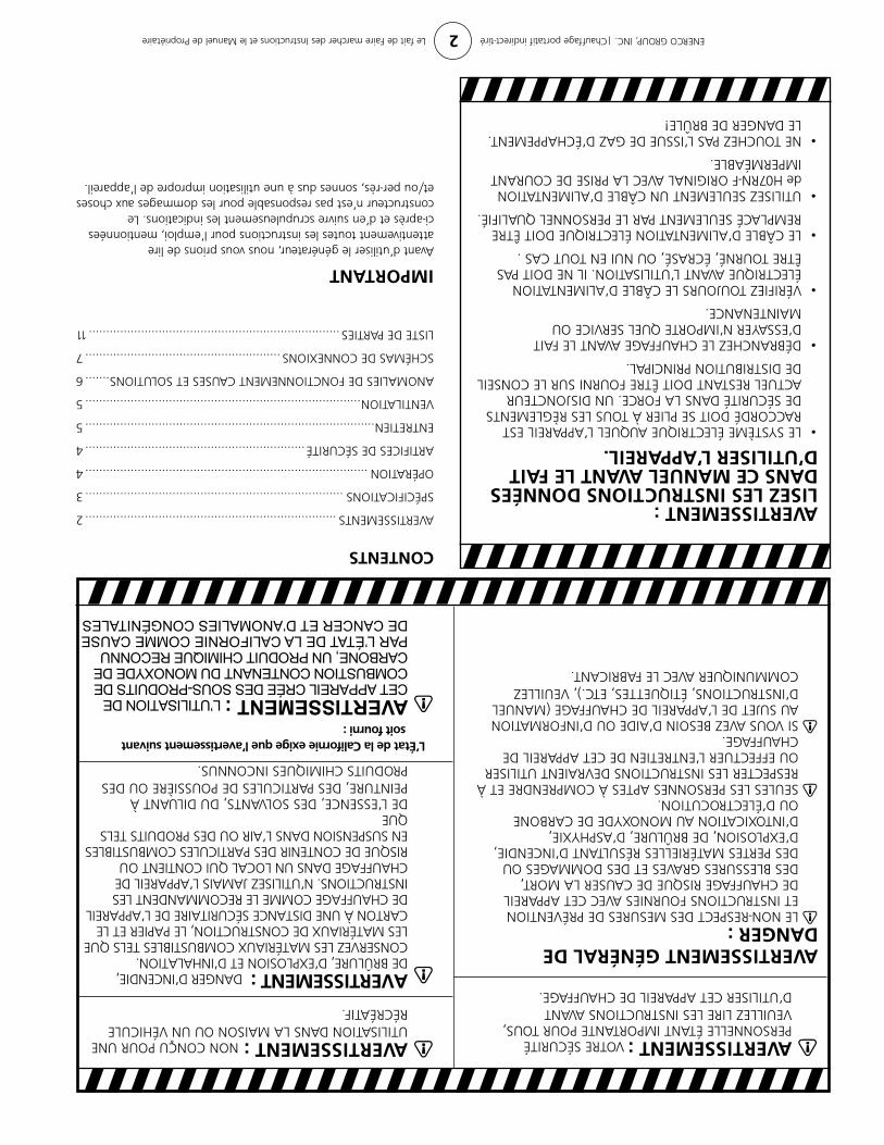
AVERTISSEMENT : dANGeR d’INCeNdIe, de BRÛLURe, d’eXPLoSIoN eT d’INHALATIoN. CoNSeRVeZ LeS MATÉRIAUX CoMBUSTIBLeS TeLS QUe LeS MATÉRIAUX de CoNSTRUCTIoN, Le PAPIeR eT Le CARToN À UNe dISTANCe SÉCURITAIRe de L’APPAReIL de CHAUFFAGe CoMMe Le ReCoMMANdeNT LeS INSTRUCTIoNS. N’UTILISeZ JAMAIS L’APPAReIL de CHAUFFAGe dANS UN LoCAL QUI CoNTIeNT oU RISQUe de CoNTeNIR deS PARTICULeS CoMBUSTIBLeS eN SUSPeNSIoN dANS L’AIR oU deS PRodUITS TeLS QUe de L’eSSeNCe, deS SoLVANTS, dU dILUANT À PeINTURe, deS PARTICULeS de PoUSSIèRe oU deS PRodUITS CHIMIQUeS INCoNNUS.
AVERTISSEMENT : L’UTILISATION DE CET APPAREIL CRÉE DES SOUS-PRODUITS DE COMBUSTION CONTENANT DU MONOXYDE DE CARBONE, UN PRODUIT CHIMIQUE RECONNU PAR L’ÉTAT DE LA CALIFORNIE COMME CAUSE DE CANCER ET D’ANOMALIES CONGÉNITALES
AVERTISSEMENT GÉNÉRAL DE DANGER :
LE NON-RESPECT DES MESURES DE PRÉVENTION eT INSTRUCTIoNS FoURNIeS AVeC CeT APPAReIL de CHAUFFAGe RISQUe de CAUSeR LA MoRT, deS BLeSSUReS GRAVeS eT deS doMMAGeS oU deS PeRTeS MATÉRIeLLeS RÉSULTANT d’INCeNdIe, d’eXPLoSIoN, de BRÛLURe, d’ASPHYXIe, d’INToXICATIoN AU MoNoXYde de CARBoNe oU d’ÉLeCTRoCUTIoN.
SeULeS LeS PeRSoNNeS APTeS À CoMPReNdRe eT À ReSPeCTeR LeS INSTRUCTIoNS deVRAIeNT UTILISeR oU eFFeCTUeR L’eNTReTIeN de CeT APPAReIL de CHAUFFAGe.
SI VoUS AVeZ BeSoIN d’AIde oU d’INFoRMATIoN AU SUJeT de L’APPAReIL de CHAUFFAGe (MANUeL d’INSTRUCTIoNS, ÉTIQUeTTeS, eTC.), VeUILLeZ CoMMUNIQUeR AVeC Le FABRICANT.
AVERTISSEMENT : NoN CoNÇU PoUR UNe UTILISATIoN dANS LA MAISoN oU UN VÉHICULe RÉCRÉATIF.
AVERTISSEMENT : VoTRe SÉCURITÉ PeRSoNNeLLe ÉTANT IMPoRTANTe PoUR ToUS, VeUILLeZ LIRe LeS INSTRUCTIoNS AVANT d’UTILISeR CeT APPAReIL de CHAUFFAGe.
L’État de la Californie exige que l’avertissement suivant soit fourni :
AVERTISSEMENT : LISEZ LES INSTRUCTIONS DONNÉES DANS CE MANUEL AVANT LE FAIT D’UTILISER L’APPAREIL.• LE SYSTÈME ÉLECTRIQUE AUQUEL L’APPAREIL EST
RACCoRdÉ doIT Se PLIeR À ToUS LeS RèGLeMeNTS de SÉCURITÉ dANS LA FoRCe. UN dISJoNCTeUR ACTUeL ReSTANT doIT ÊTRe FoURNI SUR Le CoNSeIL de dISTRIBUTIoN PRINCIPAL.
• DÉBRANCHEZ LE CHAUFFAGE AVANT LE FAIT d’eSSAYeR N’IMPoRTe QUeL SeRVICe oU MAINTeNANCe.
• VÉRIFIEZ TOUJOURS LE CÂBLE D’ALIMENTATION ÉLeCTRIQUe AVANT L’UTILISATIoN. IL Ne doIT PAS ÊTRe ToURNÉ, ÉCRASÉ, oU NUI eN ToUT CAS .
• LE CÂBLE D’ALIMENTATION ÉLECTRIQUE DOIT ÊTRE ReMPLACÉ SeULeMeNT PAR Le PeRSoNNeL QUALIFIÉ.
• UTILISEZ SEULEMENT UN CÂBLE D’ALIMENTATION de H07RN-F ORIGINAL AVEC LA PRISE DE COURANT IMPeRMÉABLe.
• NE TOUCHEZ PAS L’ISSUE DE GAZ D’ÉCHAPPEMENT. Le dANGeR de BRÛLe!
CONTENTS
AVeRTISSeMeNTS ........................................................................2
SPÉCIFICATIoNS ..........................................................................3
oPÉRATIoN .................................................................................4
ARTIFICeS de SÉCURITÉ ...............................................................4
eNTReTIeN ...................................................................................5
VeNTILATIoN ...............................................................................5
ANoMALIeS de FoNCTIoNNeMeNT CAUSeS eT SoLUTIoNS .......6
SCHÉMAS de CoNNeXIoNS ........................................................7
LISTe de PARTIeS ........................................................................11
IMPORTANTAvant d’utiliser le générateur, nous vous prions de lire attentivement toutes les instructions pour l’emploi, mentionnées ci-après et d’en suivre scrupuleusement les indications. Le constructeur n’est pas responsable pour les dommages aux choses et/ou per-rès, sonnes dus à une utilisation impropre de l’appareil.

06/11 #50120 Rev A ENERCO GROUP, INC., 4560 W. 160TH ST., CLEVELAND, OHIO 44135 • 800-251-0001
INDIRECT TIRÉ CHAUFFAGE PORTATIF
Si les informations dans ce manuel ne sont pas suivis exactement, un feu ou une explosion peuvent s’ensuivre en provoquant le dommage de propriété, la blessure personnelle ou la perte de vie.
ATTENTION:
— Ne conserver pas ou utiliser de l’essence ou d’autres vapeurs inflammables et de liquides aux alentours de cela ou autre appareil.— Le service doit être exécuté par une agence de service qualifiée.
C’est un chauffage portatif déchargé. L’air de combustion adéquat et la ventilation doivent être fournis. Faites allusion à la page 5.
MO
DÈL
E
LISEZ SOIGNEUSEMENT LES INSTRUCTIONS : Lisez et observez toutes les instructions. Conservez les instructions pour vous y référer ultérieurement. Interdisez à quiconque n’ayant pas lu les présentes instructions d’assembler, d’allumer, de régler ou de faire fonctionner cet appareil de chauffage.
1000ID, 2000ID 3000ID
GUIDE D’UTILISATION ET INSTRUCTIONS DE FONCTIONNEMENT
MR. HEATERHEATSTAR BY ENERCO
1000ID, 2000ID 3000ID, 4000ID
MO
DÈL
E