saviosavioclima.ru/up/pdf/08324be19f060528b5411f81fc112712.pdf · indice summary caratteristiche...
TRANSCRIPT

SAVIO S.r.l.

INDICE SUMMARY CARATTERISTICHE TECNICHE
Pag. 3
TECHNICAL FEATURES
Pag. 3
CONCETTI GENERALI SUI VENTILATORI
Pag. 4
GENERAL PRINCIPLES OF THE FAN DESIGN
Pag. 5
DIMENSIONI D’INGOMBRO E PRESTAZIONI
Pag. 8-27 OVERALL DIMENSIONS AND PERFORMANCE
Pag. 8-27
BASAMENTI Pag. 28 BEDPLATE Pag. 28
GIUNTI ANTIVIBRANTI Pag. 29 VIBRATION-DAMPING Pag. 29
RETI / VALVOLE A FARFALLA Pag. 30 NET / TROTTLE VALVE Pag. 30
REGOLATORI DI PORTATA
Pag. 31 FLOW REGULATORS Pag. 31
SOMMAIRE INHALTSANGABE CARACTERISTIQUES TECHNIQUES
Pag. 3
TECHNISCHE MERKMALE
Pag. 3
PRINCIPES GENERAUX DES VENTILATEURS
Pag. 6
ALLGEMEINE ANGABEN
BER DIE VENTILATOREN Pag. 7
DIMENS. D’ENCOMBREMENT ET PERFORMANCES
Pag. 8-27 ABMESSUNGEN UND LEISTUNGSTABELLE
Pag. 8-27
EMBASE Pag. 28 GRUNDRAHMEN Pag. 28
JOINTS ANTIVIBRATIONES Pag. 29 ELASTICHE VERBINDUNGEN Pag. 29
GRILLE / SOUPAPE RONDE Pag. 30 SCHUTZGITTER / DROSSELKLAPPE Pag. 30
RÉGULATEURS DE DÉBIT
Pag. 31 DURCHFLUSS REGLER Pag. 31
SAVIO S.r.l.
2

CARATTERISTICHE TECNICHE Serie di ventilatori con accoppiamento a trasmissione per medi e pressioni , idonee per il trasporto di fumi e po lveri, in miscela con l’aria fino alla temperatura massima di +80°C. Questi ventilatori sono inoltre caratterizzati da una curva della potenza assorbita molto piatta, tale da non sovraccaricare il motore nemmeno funzionando a bocche libere. Si installano nelle falegnamerie per il trasporto di segature e trucioli di legno, con esclusione di materiali filamentosi, nelle industrie meccaniche per l’aspirazione di sbavature e smerigliature metalliche, nei trasporti pneumatici dei cementifici, ceramiche mulini, mangimifici, concerie, fonderie, nelle industrie tessili, chimiche, ed in generale in tutte quelle applicazioni dove necessita il trasporto di aria nociva con bassa e media pressione Per temperature del fluido trasportato superiori a 90°C fino a 350°C viene calettata sull’albero fra supporto e coclea una ventolina particolare; inoltre il ventilatore viene verniciato con vernice speciale all’alluminio per alte temperature.
COSTRUZIONECoclea in acciaio a giunzione graffata di forte spessore. Girante a pale rovesce in acciaio saldato a profilo costante. Motore in forma B3 50 Hz V. 230/400 per potenze fino a 4 kW e 400/690 per potenze superiori.
TECHNICAL FEATURES Set of belts and pulleys transmission fans for middle pressure flow rates ,suitable for conveyance of fumes and dust, mixed with air, having +80° C max. temperature. Besides these fans are characterized by a very flat curve of the absorbed power, in order not to overload the motor neither when working with open inlets. They are assembled in j oineries for transporting saw dust and wooden shavings, excluding filamentous material, in mechanical industries for sucking in metal chips, in pneumatic transport of the cement factories, ceramic factories, mills, fodder factories, tanneries, foundries, in textile and chemical Industries and in general in all those applications where it is necessary to transport harmful air with low and medium pressure For temperatures of the transported fluid higher than 90°C up to 350°C a small heat stopping cooling fan is mounted on the shaft between support and housing; besides the fan is painted with a special aluminum paint suitable for high temperatures.
CONSTRUCTION FEATURES Galvanized steel fan cas ing with high-thickness clinched junction. Reverse-blade impe ller made steady -profile welded steel. Motor Form B3, 50 Hz, 230/400 Volts for power up to 4 kW and 400/690 Volts for higher ratings.
CARACTERISTIQUES TECHNIQUES Série de ventilateurs avec transmission poulies et courroies pour pressions intermédiaires, adaptés au transport des fumées et des poussières mélangées à l’air, jusqu’à une température maximale de +80°C. Ces ventilateurs sont en outre caractérisés d’une courbe de puissance absorbe très plate, afin de ne pas surcharger le moteur même fonctionnant avec les bouches libres. Ils s’installent dans les menuiseries pour le transport de la sciure et des copeaux en bois, avec exclusion de matériels filamenteux, dans les industries mécaniques pour l’aspiration d’ébavurages et polissage métalliques, dans les transports pneumatiques, des cimenterie, céramiques, moulins, fabriques agro-alimentaires, tanneries, fonderies, industries textiles, chimiques, et en général en toutes le applications ou l’on demande le transport de l’air nuisible avec basse et moyenne pression. Pour des températures de fluide transporté supérieures à 90°C jusqu’à 350°C, on place sur l’arbre une turbine de refroidissement qui protège de la chaleur entre la chaise et la coque; en outre, on peint le ventilateur avec une peinture spéciale à l’aluminium pour hautes températures.
CONSTRUCTIONVirole en acier zingué à jonction accolée de forte épaisseur. Roue à aubes renversées en acier soudé à profil constant. Moteur en forme B3, 50 Hz, 230/400 V pour des puissances jusqu’à 4 kW et 400/690 V pour les puissances supérieures.
TECHNISCHE MERKMALE Serie Ventilatoren mit Riemenantrieb für mittlere Drücke, geeignet zum Transport von Rauch und Staub gemischt mit Luft bis zu einer Höchsttemperatur von +80°C. Das Hauptmerkmal dieser Serie ist eine flache Kennlinie der Leistungsaufnahme, welche eine Überlastung des E-Motors verhindert. Die Verwendungsmöglichkeiten dieser Ventilatoren sind vielfaltig so z.B.: in Tischlereien zur Holzmehl- und Späne Absaugung, in der metallverarbeitenden Industrie (Absaugung von Metellspänen), für pneumatische Förderanlagen in Zeme nt- und Keramik Fabriken, Mühlen, Futterfabriken, Gerbereien, Gießereien, Chemie und Textilindustrie und in allen Industriebetrieben wo staubige Luft abgesaugt werden muss. Für Temperaturen, des geförderten Mediums, von 90°C bis 350°C wird an der Welle, zwischen Lager und Gehäuse, ein Kühlflügel aufgezogen und der Ventilatoren mit Aluminiumfarbe, für hohe Temperaturen, lackiert. BAUAUSFUHRUNG Förderschnecke aus verzinktem Stahl mit starkbemess ener Verklammerung. Laufrad mit Kippflügeln aus geschweißtem Stahl mit konstantem Profil. Motor in der Form B3 50 Hz 230/400 V für Leistungen bis zu 4 kW und 400/690 für höhere Leistungen.
SAVIO S.r.l.
3

CONCETTI GENERALI SUI VENTILATORI
1) PARAMETRI I principali parametri che distinguono un ventilatore sono quattro:
Portata (V) Pressione (p) Rendimento ( ) Velocità di rotazione (n° min.-1)
1.1) Portata: La portata è la quantità di fluido movimentata dal ventilatore, in termini di volume, nell’unità di tempo e si esprime
normalmente in m3/h, m3/min., m3/sec.
1.2) Pressione: La pressione totale (pt) è la somma tra la pressione statica (pst), ovvero l’energia necessaria a vincere gli attriti opposti dall’impianto e la pressione dinamica (pd) o energia cinetica impressa al fluido in movimento (pt = pst + pd). La pressione dinamica dipende dalla velocità (v) e dal peso specifico del fluido (y).
1 pd = v2 2
Dove:
pd
v
= pressione dinamica = peso specifico del fluido = velocità del fluido alla bocca del ventilatore interessata dall’impianto
(Pa) (Kg/m3) (m/sec)
V v = A
Dove:
V A v
= portata = sezione della bocca interessata dall’impianto = velocità del fluido alla bocca del ventilatore interessata dall’impianto
(m3/sec) (m2) (m/sec)
1.3) Rendimento: Il rendimento è il rapporto tra l’energia resa dal ventilatore e quella assorbita dal motore che aziona il ventilatore stesso.
V pt =
6120 P Dove:
V = rendimento = portata
(m3/min)
P pt
= potenza assorbita = pressione totale
(kW) (daPa)
1.4) Velocità di rotazione: La velocità di rotazione è il nr. di giri che la girante del ventilatore deve compiere per fornire le caratteristiche richieste. Al variare del nr. dei giri (n), mantenendo costante il peso specifico del fluido ( ), si ottengono le seguenti variazioni:
La portata (V) è direttamente proporzionale alla velocità di rotazione quindi : n1 V1 = V n
Dove: n V
= velocità di rot.ne = portata
V1 n1
= nuova portata ottenuta al variare della velocità di rot. = nuova velocità di rotazione
La pressione totale (pt) varia con il quadrato del rapporto delle velocità di rotazione quindi: n1 2 pt1 = pt n
Dove: n pt
= velocità di rot.ne = pressione tot.
pt1n1
= nuova pressione tot. ottenuta al variare della vel. di rot.= nuova velocità di rotazione
La potenza assorbita (P) varia con il cubo del rapporto delle velocità di rotazione quindi: n1 3 P1 = P n
Dove: n P
= velocità di rot.ne = potenza ass.
P1n1
= nuova potenza ass. ottenuta al variare della vel. di rot. = nuova velocità di rotazione
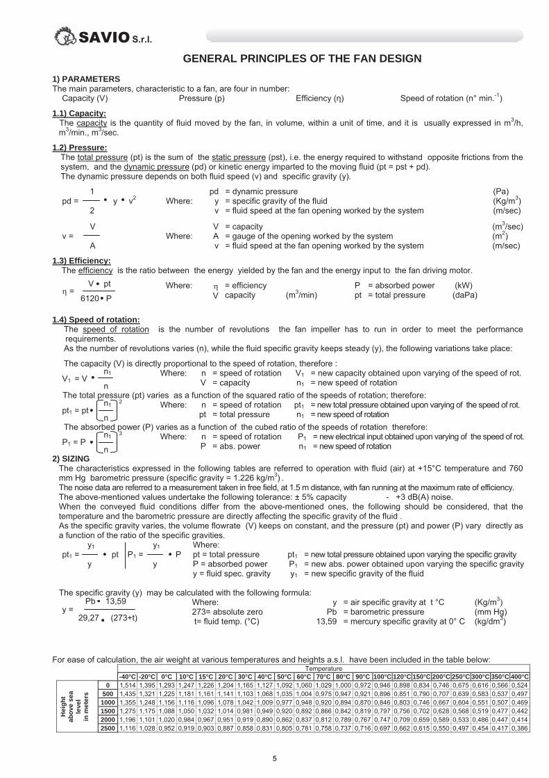
2) DIMENSIONAMENTO Le caratteristiche da noi espresse nelle tabelle che seguono, sono riferite al funzionamento con fluido (aria) alla temperatura di + 15°C e con pressione barometrica di 760 mm Hg (peso specifico = 1.226 kg/m3) . I dati relativi alla rumorosità sono riferiti ad una misurazione in campo libero, alla distanza di 1,5 m. con ventilatore funzionante alla portata di massimo rendimento. I valori riportati sono soggetti alle seguenti tolleranze: portata ± 5% - rumorosità +3 dB(A). Quando le condizioni del fluido trasportato differiscono da quelle sopra citate è necessario tenere conto che temperatura e pressione barometrica, influenzano direttamente il peso specifico del fluido stesso. Al variare del peso specifico, la portata (V) in termini di volume rimane costante, la pressione (pt) e la potenza (P) varieranno direttamente con il rapporto dei pesi specifici. y1 pt1 = pt
y1 P1 = P y
Dove: pt = pressione totale P = potenza assorbita y = peso spec. fluido
pt1P1y1
= nuova pressione tot. ottenuta al variare del peso specifico = nuova potenza ass. ottenuta al variare del peso specifico = nuovo peso specifico del fluido
Il peso specifico (y) si può calcolare con la seguente formula: Pb 13,59 y = 29,27 (273+t)
Dove: 273= zero assoluto t= temp. del fluido (°C)
yPb
13,59
= peso specifico dell’ aria a t °C = pressione barometrica = peso specifico mercurio a 0° C
(Kg/m3) (mm Hg) (kg/dm3)
Per maggior facilità di calcolo, riportiamo il peso dell’aria alle varie temperature ed alle varie altitudini:
Temperatura -40°C -20°C 0°C 10°C 15°C 20°C 30°C 40°C 50°C 60°C 70°C 80°C 90°C 100°C 120°C 150°C 200°C 250°C 300°C 350°C 400°C
Alti
tudi
ne
ms.
l.m.
0 1,514 1,395 1,293 1,247 1,226 1,204 1,165 1,127 1,092 1,060 1,029 1,000 0,972 0,946 0,898 0,834 0,746 0,675 0,616 0,566 0,524500 1,435 1,321 1,225 1,181 1,161 1,141 1,103 1,068 1,035 1,004 0,975 0,947 0,921 0,896 0,851 0,790 0,707 0,639 0,583 0,537 0,497
1000 1,355 1,248 1,156 1,116 1,096 1,078 1,042 1,009 0,977 0,948 0,920 0,894 0,870 0,846 0,803 0,746 0,667 0,604 0,551 0,507 0,4691500 1,275 1,175 1,088 1,050 1,032 1,014 0,981 0,949 0,920 0,892 0,866 0,842 0,819 0,797 0,756 0,702 0,628 0,568 0,519 0,477 0,4422000 1,196 1,101 1,020 0,984 0,967 0,951 0,919 0,890 0,862 0,837 0,812 0,789 0,767 0,747 0,709 0,659 0,589 0,533 0,486 0,447 0,4142500 1,116 1,028 0,952 0,919 0,903 0,887 0,858 0,831 0,805 0,781 0,758 0,737 0,716 0,697 0,662 0,615 0,550 0,497 0,454 0,417 0,386
SAVIO S.r.l.
4
GENERAL PRINCIPLES OF THE FAN DESIGN
1) PARAMETERS The main parameters, characteristic to a fan, are four in number:
Capacity (V) Pressure (p) Efficiency ( ) Speed of rotation (n° min.-1)
1.1) Capacity: The capacity is the quantity of fluid moved by the fan, in volume, within a unit of time, and it is usually expressed in m3/h,
m3/min., m3/sec.
1.2) Pressure: The total pressure (pt) is the sum of the static pressure (pst), i.e. the energy required to withstand opposite frictions from the system, and the dynamic pressure (pd) or kinetic energy imparted to the moving fluid (pt = pst + pd). The dynamic pressure depends on both fluid speed (v) and specific gravity (y).
1 pd = v2 2
Where:
pd
v
= dynamic pressure = specific gravity of the fluid = fluid speed at the fan opening worked by the system
(Pa) (Kg/m3) (m/sec)
V v = A
Where:
V A v
= capacity = gauge of the opening worked by the system = fluid speed at the fan opening worked by the system
(m3/sec) (m2) (m/sec)
1.3) Efficiency: The efficiency is the ratio between the energy yielded by the fan and the energy input to the fan driving motor.
V pt =
6120 P Where:
V = efficiency capacity
(m3/min)
P pt
= absorbed power = total pressure
(kW) (daPa)
1.4) Speed of rotation: The speed of rotation is the number of revolutions the fan impeller has to run in order to meet the performance
requirements. As the number of revolutions varies (n), while the fluid specific gravity keeps steady ( ), the following variations take place:
The capacity (V) is directly proportional to the speed of rotation, therefore : n1 V1 = V n
Where: n V
= speed of rotation = capacity
V1 n1
= new capacity obtained upon varying of the speed of rot. = new speed of rotation
The total pressure (pt) varies as a function of the squared ratio of the speeds of rotation; therefore: n1 2 pt1 = pt n
Where: n pt
= speed of rotation = total pressure
pt1n1
= new total pressure obtained upon varying of the speed of rot. = new speed of rotation
The absorbed power (P) varies as a function of the cubed ratio of the speeds of rotation therefore: n1 3 P1 = P n
Where: n P
= speed of rotation = abs. power
P1n1
= new electrical input obtained upon varying of the speed of rot. = new speed of rotation
2) SIZING The characteristics expressed in the following tables are referred to operation with fluid (air) at +15°C temperature and 760 mm Hg barometric pressure (specific gravity = 1.226 kg/m3) . The noise data are referred to a measurement taken in free field, at 1.5 m distance, with fan running at the maximum rate of efficiency. The above-mentioned values undertake the following tolerance: ± 5% capacity - +3 dB(A) noise. When the conveyed fluid conditions differ from the above-mentioned ones, the following should be considered, that the temperature and the barometric pressure are directly affecting the specific gravity of the fluid . As the specific gravity varies, the volume flowrate (V) keeps on constant, and the pressure (pt) and power (P) vary directly as a function of the ratio of the specific gravities. y1 pt1 = pt
y1 P1 = P y
Where: pt = total pressure P = absorbed power y = fluid spec. gravity
pt1P1y1
= new total pressure obtained upon varying the specific gravity = new abs. power obtained upon varying the specific gravity = new specific gravity of the fluid
The specific gravity (y) may be calculated with the following formula: Pb 13,59 y = 29,27 (273+t)
Where: 273= absolute zero t= fluid temp. (°C)
yPb
13,59
= air specific gravity at t °C = barometric pressure = mercury specific gravity at 0° C
(Kg/m3) (mm Hg) (kg/dm3)
For ease of calculation, the air weight at various temperatures and heights a.s.l. have been included in the table below:
Temperature -40°C -20°C 0°C 10°C 15°C 20°C 30°C 40°C 50°C 60°C 70°C 80°C 90°C 100°C 120°C 150°C 200°C 250°C 300°C 350°C 400°C
Hei
ght
abov
e se
a le
vel
in m
eter
s
0 1,514 1,395 1,293 1,247 1,226 1,204 1,165 1,127 1,092 1,060 1,029 1,000 0,972 0,946 0,898 0,834 0,746 0,675 0,616 0,566 0,524500 1,435 1,321 1,225 1,181 1,161 1,141 1,103 1,068 1,035 1,004 0,975 0,947 0,921 0,896 0,851 0,790 0,707 0,639 0,583 0,537 0,497
1000 1,355 1,248 1,156 1,116 1,096 1,078 1,042 1,009 0,977 0,948 0,920 0,894 0,870 0,846 0,803 0,746 0,667 0,604 0,551 0,507 0,4691500 1,275 1,175 1,088 1,050 1,032 1,014 0,981 0,949 0,920 0,892 0,866 0,842 0,819 0,797 0,756 0,702 0,628 0,568 0,519 0,477 0,4422000 1,196 1,101 1,020 0,984 0,967 0,951 0,919 0,890 0,862 0,837 0,812 0,789 0,767 0,747 0,709 0,659 0,589 0,533 0,486 0,447 0,4142500 1,116 1,028 0,952 0,919 0,903 0,887 0,858 0,831 0,805 0,781 0,758 0,737 0,716 0,697 0,662 0,615 0,550 0,497 0,454 0,417 0,386
SAVIO S.r.l.
5

PRINCIPES GENERAUX DES VENTILATEURS
1) PARAMETRES Les principaux paramètres qui identifient un ventilateur sont au nombre de quatre :
Débit (V) Pression (p) Rendement ( ) Vitesse de rotation (n° min.-1)
1.1) Débit : Le débit est la quantité de fluide mise en mouvement par le ventilateur, en terme de volume dans l’unité de temps, et
s’exprime généralement en m3/h, m3/min, m3/s. 1.2) Pression :
La pression totale (pt) est la somme de la pression statique (pst), c’est-à-dire l’énergie nécessaire pour vaincre les frottements dus à l’installation, et de la pression dynamique (pd) ou énergie cinétique imprimée au fluide en mouvement (pt = pst + pd). La pression dynamique dépend de la vitesse (v) et du poids spécifique du fluide (y).
1 pd = v2 2
Où :
pd
v
= pression dynamique = poids spécifique du fluide = vitesse du fluide à la bouche du ventilateur, souhaitée dans l’installation
(Pa) (kg/m3) (m/s)
V v = A
Où :
V A v
= débit = section de la bouche, souhaitée dans l’installation = vitesse du fluide à la bouche du ventilateur, souhaitée dans l’installation
(m3/s) (m2) (m/s)
1.3) Rendement : Le rendement est le rapport entre l’énergie restituée par le ventilateur et l’énergie absorbée par le moteur actionnant le ventilateur.
V pt =
6120 P Où :
V = rendement =débit
(m3/min)
P pt
= puissance absorbée = pression totale
(kW) (daPa)
1.4) Vitesse de rotation : La vitesse de rotation est le nombre de tours que la roue du ventilateur doit accomplir pour fournir les caractéristiques
requises. En faisant varier le nombre de tours (n) et en maintenant constant le poids spécifique du fluide ( ), on obtient les variations
suivantes : Le débit (V) est directement proportionnel à la vitesse de rotation, donc :
n1 V1 = V n
Où : n V
= vitesse de rotation = débit
V1 n1
= nouveau débit obtenu par variation de la vitesse de rotation = nouvelle vitesse de rotation
La pression totale (pt) varie comme le carré du rapport des vitesses de rotation, donc : n1 2 pt1 = pt n
Où : n pt
= vitesse de rotation = pression totale
pt1n1
= nouvelle pression totale obtenue par variation de la vitesse de rot. = nouvelle vitesse de rotation
La puissance absorbée (P) varie comme le cube du rapport des vitesses de rotation, donc : n1 3 P1 = P n
Où : n P
= vitesse de rotation = puissance absorbée
P1n1
= nouvelle puissance absorbée obtenue par variation de la vitesse de rot. = nouvelle vitesse de rotation
2) DIMENSIONNEMENT Les caractéristiques, que nous reportons dans les tableaux suivants, se réfèrent à un fonctionnement avec un fluide (l’air) à la température de + 15°C et sous une pression barométrique de 760 mm Hg (poids spécifique = 1.226 kg/m3). Les données relatives au bruit se réfèrent à une mesure en champ libre, à la distance de 1,5 m, lorsque le ventilateur fonctionne au débit maximal. Les valeurs reportées sont sujettes aux tolérances suivantes : débit ± 5% - bruit +3 dB(A). Lorsque les conditions du fluide véhiculé diffèrent de celles indiquées ci-dessus, il faut tenir compte de la température et de la pression barométrique qui influent directement sur le poids spécifique du fluide. Lorsque le poids spécifique varie, le débit (V) reste constant en volume, la pression (pt) et la puissance (P) varient directement avec le rapport des poids spécifiques. y1 pt1 = pt
y1 P1 = P y
Où : pt = pression totale P = puissance absorbée y = poids spécifique du fluide
pt1P1y1
= nouvelle pression totale obtenue par variation du poids spécifique =nouvelle puissance absorbée obtenue par variation du poids spéc. = nouveau poids spécifique du fluide
Le poids spécifique (y) se calcule à l’aide de la formule suivante : Pb 13,59 y = 29,27 (273+t)
Où : 273 = zéro absolu t= température du fluide (°C)
yPb
13,59
= poids spécifique de l’air à t °C = pression barométrique = poids spécifique du mercure à 0° C
(kg/m3) (mm Hg) (kg/dm3)
Pour faciliter le calcul, le poids de l’air, sous différentes altitudes et différentes températures, est reporté ci-dessous :
Température -40°C -20°C 0°C 10°C 15°C 20°C 30°C 40°C 50°C 60°C 70°C 80°C 90°C 100°C 120°C 150°C 200°C 250°C 300°C 350°C 400°C
Alti
tude
en
mèt
res
au-d
essu
sdu
niv
eau
de
la m
er
0 1,514 1,395 1,293 1,247 1,226 1,204 1,165 1,127 1,092 1,060 1,029 1,000 0,972 0,946 0,898 0,834 0,746 0,675 0,616 0,566 0,524500 1,435 1,321 1,225 1,181 1,161 1,141 1,103 1,068 1,035 1,004 0,975 0,947 0,921 0,896 0,851 0,790 0,707 0,639 0,583 0,537 0,497
1000 1,355 1,248 1,156 1,116 1,096 1,078 1,042 1,009 0,977 0,948 0,920 0,894 0,870 0,846 0,803 0,746 0,667 0,604 0,551 0,507 0,4691500 1,275 1,175 1,088 1,050 1,032 1,014 0,981 0,949 0,920 0,892 0,866 0,842 0,819 0,797 0,756 0,702 0,628 0,568 0,519 0,477 0,4422000 1,196 1,101 1,020 0,984 0,967 0,951 0,919 0,890 0,862 0,837 0,812 0,789 0,767 0,747 0,709 0,659 0,589 0,533 0,486 0,447 0,4142500 1,116 1,028 0,952 0,919 0,903 0,887 0,858 0,831 0,805 0,781 0,758 0,737 0,716 0,697 0,662 0,615 0,550 0,497 0,454 0,417 0,386
SAVIO S.r.l.
6

ALLGEMEINE ANGABEN ÜBER DIE VENTILATOREN
1) PARAMETER Die hauptsächlichen Parameter, die einen Ventilator auszeichnen, sind vier :
Fördermenge (V) Druck (p) Leistung ( ) Drehgeschwindigkeit (n° min.-1)
1.1) Fördermenge: Die Fördermenge ist das Volumen der Masse des vom Ventilator bewegten Fluids in der Zeiteinheit und wird normalerweise
ausgedrückt in m3/h, m3/min., m3/sec.
1.2) Druck: Der Gesamtdruck (pt) ist die Summe zwischen dem statischen Druck und der für die Überwindung der von der Anlage entgegengesetzten Reibungen erforderlichen Energie und dem dynamischen Druck (pd) oder der kinetischen Energie, die dem in Bewegung befindlichen Fluid eingeprägt ist (pt = pst + pd). Der dynamische Druck hängt von der Geschwindigkeit (v) und vom spezifischen Gewicht des Fluids (y) ab.
1 pd = v2 2
Wo:
pd
v
= dynamischer Druck = spezifisches Gewicht des Fluids = Geschwindigkeit des Fluids an der Düse des von der Anlage interessierten Ventilators
(Pa) (Kg/m3) (m/sec)
V v = A
Wo:
V A v
= Fördermenge = Schnitt der von der Anlage interessierten Düse = Geschwindigkeit des Fluids an der Düse des von der Anlage interessierten Ventilators
(m3/sec) (m2) (m/sec)
1.3) Leistung: Die Leistung ist das Verhältnis zwischen der vom Ventilator abgegebenen Energie und der vom Motor, der den Ventilator antreibt, aufgenommenen.
V pt =
6120 P Wo:
V = Leistung = Fördermenge
(m3/min)
P pt
= aufgen.Kraft = Gesamtdruck
(kW) (daPa)
1.4) Drehgeschwindigkeit: Die Drehgeschwindigkeit ist die Anzahl der Umdrehungen, die das Laufrad des Ventilators ausführen muß, um die verlangten
Eigenschaften zu erfüllen. Bei Veränderung der Umdrehungszahl (n) und bei konstanter Beibehaltung des spezifischen Gewichts des Fluids ( ),
werden folgende Variationen erreicht :
Die Fördermenge (V) ist direkt proportionell zur Drehgeschwindigkeit, also : n1 V1 = V n
Wo: n V
= Drehgeschwind. = Fördermenge
V1 n1
= neue F.Menge,erreicht b.Variat.d.Drehgeschwindigk. = neue Drehgeschwindigkeit
Der Gesamtdruck (pt) variiert mit der Quadratzahl des Verhältnisses der Drehgeschwindigkeiten, also: n1 2 pt1 = pt n
Wo: n pt
= Drehgeschw. = Gesamtdruck
pt1n1
= neuer Ges.Druck,erreicht b.Variat.d.Drehgeschw. = neue Drehgeschwindigkeit
Die aufgenommene Kraft (P) variiert mit der Kubikzahl des Verhältnisses der Drehgeschwindigkeiten, also: n1 3 P1 = P n
Wo: n P
= Drehgeschwind. = aufgen. Kraft
P1n1
= neue aufgen.Kraft, erreicht b.Variat.d.Drehgeschw. = neue Drehgeschwindigkeit
2) BEMESSUNG Die von uns in den folgenden Tabellen ausgedrückten Eigenschaften beziehen sich auf den Betrieb mit Fluid (Luft) bei Temperatur von + 15° und barometrischem Druck von 760 mm Hg (spezifisches Gewicht = 1.226 kg/m3) . Die das Geräusch betreffenden Daten beziehen sich auf eine Messung auf freiem Feld in einer Entfernung von 1,5 m und Ventilator, funktionierend mit Höchstleistungskraft. Die angegebenen Werte unterliegen den folgenden Toleranzen : Fördermenge ± 5% - Geräusch +3 dB(A). Wenn die Bedingungen des bewegten Fluids sich von den o.a. unterscheiden ist zu beachten, daß Temperatur und barometrischer Druck direkt auf das spezifische Gewicht des Fluids einwirken. Bei Variation des spezifischen Gewichts bleibt die Fördermenge (V) in bezug auf das Volumen konstant, während der Druck (pt) und die Kraft (P) direkt mit dem Verhältnis der spezifischen Gewichte variieren. y1 pt1 = pt
y1 P1 = P y
Wo: pt = Gesamtdruck P = aufgen. Kraft y = spez.Gew. Fluid
pt1P1y1
= neuer Gesamtdruck, erreicht b.Variat. d. spez.Gew. = neue aufgen.Kraft, erreicht b.Variat. d. spez.Gew. = spezifisches Gewicht des Fluids
Das spezifische Gewicht (y) kann mit der folgenden Formel berechnet werden : Pb 13,59 y = 29,27 (273+t)
Wo: 273= absolute Null t= Temperatur d. Fluids (°C)
yPb
13,59
= spez.Gew. d.Luft b. temp. °C = barometrischer Druck = spez.Gew.d.Quecksilbers b.0°C
(Kg/m3) (mm Hg)(kg/dm3)
Zur Erleichterung der Berechnung geben wir das Gewicht der Luft bei den verschiedenen Temperaturen und Höhen an:
Temperatur -40°C -20°C 0°C 10°C 15°C 20°C 30°C 40°C 50°C 60°C 70°C 80°C 90°C 100°C 120°C 150°C 200°C 250°C 300°C 350°C 400°C
Höh
e ü.
d.M
.
0 1,514 1,395 1,293 1,247 1,226 1,204 1,165 1,127 1,092 1,060 1,029 1,000 0,972 0,946 0,898 0,834 0,746 0,675 0,616 0,566 0,524500 1,435 1,321 1,225 1,181 1,161 1,141 1,103 1,068 1,035 1,004 0,975 0,947 0,921 0,896 0,851 0,790 0,707 0,639 0,583 0,537 0,497
1000 1,355 1,248 1,156 1,116 1,096 1,078 1,042 1,009 0,977 0,948 0,920 0,894 0,870 0,846 0,803 0,746 0,667 0,604 0,551 0,507 0,4691500 1,275 1,175 1,088 1,050 1,032 1,014 0,981 0,949 0,920 0,892 0,866 0,842 0,819 0,797 0,756 0,702 0,628 0,568 0,519 0,477 0,4422000 1,196 1,101 1,020 0,984 0,967 0,951 0,919 0,890 0,862 0,837 0,812 0,789 0,767 0,747 0,709 0,659 0,589 0,533 0,486 0,447 0,4142500 1,116 1,028 0,952 0,919 0,903 0,887 0,858 0,831 0,805 0,781 0,758 0,737 0,716 0,697 0,662 0,615 0,550 0,497 0,454 0,417 0,386
SAVIO S.r.l.
7

N 6 Fori Ø11.5
19
Ø921
40
104
012
281
470
014
61
165
189
130
061
430
561Ø
141
170
041
100
211
052=H
N 4 Fori Ø8
272 N 4 Fori Ø12
15
542
022
20750
6
22
6j 91
N 4 Prig. M8
57.0
55.0
73.0
52.0
81.0
21.0
ssa/wk P
5000
4500
4000
3550
3150
2750
ngiri/min
2500
%
57.0
55.0
73.0
52.0
81.0
21.0
ssa/wk P
5000
4500
4000
3550
3150
2750
ngiri/min
2500
%
Il ventilatore è orientabileThe fan is revolvableLe ventilateur est orientableVentilatorgehäuse ist drehbar
LGRD
H=250H=160H=250H=160 H=250H=250
SAVIO S.r.l.
8

N 8 Fori Ø11.5N 8 Fori Ø11.5
N 4 Fori Ø12272
15
542
022
20750
40
19
124
515
510
513=H
255
219
17078
002
535
912Ø
112
211
002
140
072
142
210
182
581Ø
6
22
6j 91
N 8 Prig. M8
4200
4500
4000
3550
3150
2750
2500
ngiri/min
5.1
1.1
57.0
55.0
52.0
73.0
ssa/wk P
%
5.1
1.1
57.0
55.0
52.0
73.0
ssa/wk P
4200
4500
4000
3550
3150
2750
2500
ngiri/min
Il ventilatore è orientabileThe fan is revolvableLe ventilateur est orientableVentilatorgehäuse ist drehbar
LGRD
H=315H=200H=315H=200 H=315H=315
SAVIO S.r.l.
9

N 10 Fori Ø11.5N 8 Fori Ø11.5
19
134
553=H
765
530
275
241
202
212
600
90
142Ø
112
422
160
492
562
230
200
211
Ø502
272 N 4 Fori Ø12
15
542
022
20750
6
22
6j 91
N 8 Prig. M8
40
4000
4500
3550
3150
2750
2500
ngiri/min
73.0
2.2
5.1
1.1
57.0
55.0
ssa/wk P
%
73.0
2.2
5.1
1.1
57.0
55.0
ssa/wk P
4000
4500
3550
3150
2750
2500
ngiri/min
Il ventilatore è orientabileThe fan is revolvableLe ventilateur est orientableVentilatorgehäuse ist drehbar
LGRD
H=355H=212H=355H=212 H=355H=355
SAVIO S.r.l.
10

8
N 10 Fori Ø11.5N 8 Fori Ø11.5
50
265
299
562Ø
922Ø
139
636
635
632
228
670
93
24
004=H
2x211
219
250
180
292
023
052
112
6j 42
27
337 N 4 Fori Ø12
22
613
082
27045
N 8 Prig. M8
%
3
2.2
5.1
1.1
57.0
55.0
ssa/wk P
4550
4000
3550
3150
2830
2500
2230
ngiri/min
%
3
2.2
5.1
1.1
57.0
55.0
ssa/wk P
4550
4000
3550
3150
2830
2500
2230
ngiri/min
Il ventilatore è orientabileThe fan is revolvableLe ventilateur est orientableVentilatorgehäuse ist drehbar
LGRD
H=400H=236H=400H=236 H=400H=400
SAVIO S.r.l.
11

6j 42
27
8
50
150
660
337 N 4 Fori Ø12
22
613
082
27045
24
054=H
114
292Ø
N 10 Fori Ø11.5N 8 Fori Ø11.5
2x521
325
292
249
280
233
063
200
082
125
552Ø
562
263
750
517
N 8 Prig. M8
%
5.5
5.7
4
3
2.2
5.1
1.1
57.0
ssa/wk P
4500
4000
3600
3150
2850
2500
2250
2000
ngiri/min
%
5.5
5.7
4
3
2.2
5.1
1.1
57.0
ssa/wk P
4500
4000
3600
3150
2850
2500
2250
2000
ngiri/min
Il ventilatore è orientabileThe fan is revolvableLe ventilateur est orientableVentilatorgehäuse ist drehbar
LGRD
H=450H=265H=450H=265 H=450H=450
SAVIO S.r.l.
12

N 8 Prig. M8
224
304
273
003
008
820
292
332
36625
005=H
Ø28
8
31
6j 82
825
60
55 405
128
172
233Ø
663
593
2x521
513
N 10 Fori Ø11.5
125
053
093
682Ø
N 4 Fori Ø14485
N 8 Fori Ø11.5
wk
ssa/P
5.7
5.5
4
3
2.2
5.1
1.1
2930
ngiri/min
4000
3550
3150
2800
2500
2250
2000
1800
%%
2930
ngiri/min
4000
3550
3150
2800
2500
2250
2000
1800
wk
ssa/P
5.7
5.5
4
3
2.2
5.1
1.1
Il ventilatore è orientabileThe fan is revolvableLe ventilateur est orientableVentilatorgehäuse ist drehbar
LGRD
H=500H=300H=500H=300 H=500H=500
SAVIO S.r.l.
13

598
328
533
41
01
915
065=H
6k 83
870
Ø38
80
663Ø
145
N 10 Fori Ø11.5
2x521553
534
504
123Ø
366
401
125
250
330
300
185
40555 25
485 N 4 Fori Ø14
093
053
N 8 Fori Ø11.5
N 8 Prig. M8
Il ventilatore è orientabileThe fan is revolvableLe ventilateur est orientableVentilatorgehäuse ist drehbar
LGRD
H=560H=335H=560H=335 H=560H=560
wk
ssa/
P
9
5.7
5.5
4
3
2.2
5.1
1.1
ngiri/min
3550
3150
2800
2500
2250
2000
1800
1600
%
2900
%
ngiri/min
3550
3150
2800
2500
2250
2000
1800
1600
2900
wk
ssa/
P
9
5.7
5.5
4
3
2.2
5.1
1.1
SAVIO S.r.l.
14

N 8 Prig. M8
589
1015
366
55345
6k 24
21
036=H
110
Ø42
160
1010
504Ø
3x521
844 004
125x2
280
332
360
084
163Ø
441
405
212
014
063
2565
560
470
N 4 Fori Ø17
N 14 Fori Ø11.5N 8 Fori Ø11.5
Il ventilatore è orientabileThe fan is revolvableLe ventilateur est orientableVentilatorgehäuse ist drehbar
LGRD
H=630H=355H=630H=355 H=630H=630
ssa/wk P
11
9
5.7
5.5
4
3
2.2
5.1
2920
ngiri/min
3150
2800
2500
2250
2000
1800
1600
1400
%%
2920
ngiri/min
3150
2800
2500
2250
2000
1800
1600
1400
wk
ssa/P
11
9
5.7
5.5
4
3
2.2
5.1
SAVIO S.r.l.
15

N 12 Prig. M8
069
410
004
1135
065=H
110
21
6k 24
45Ø42
1040
180
844Ø
366
395
315
125x2
794
035 054
3x521
014
486
604Ø
448
25470
560
65
063
230
N 4 Fori Ø17
N 12 Fori Ø11.5 N 14 Fori Ø11.5
ssa/wk P
51
11
9
5.7
5.5
4
3
2.2
5.1
ngiri/min
2800
2500
2250
2000
1800
1600
1400
1250
%%ngiri/min
2800
2500
2250
2000
1800
1600
1400
1250
ssa/wk P
51
11
9
5.7
5.5
4
3
2.2
5.1
Il ventilatore è orientabileThe fan is revolvableLe ventilateur est orientableVentilatorgehäuse ist drehbar
LGRD
H=710H=400H=560H=400 H=710H=560
SAVIO S.r.l.
16
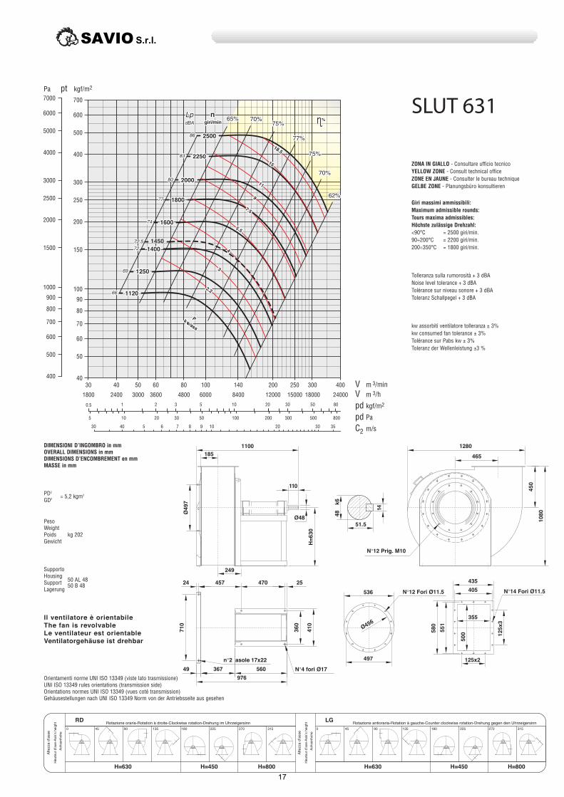
1100
976
560
470
n 2 asole 17x22
N 4 fori Ø17
24 457
49 367
014
063
25
465
1280
054
0801
110
Ø48
036=H
185
017794
Ø
249
N 12 Prig. M10
41
6k 84
51.5
405
125x2
005
355
435
155
085
654Ø
497
536
3x521
N 14 Fori Ø11.5N 12 Fori Ø11.5
Il ventilatore è orientabileThe fan is revolvableLe ventilateur est orientableVentilatorgehäuse ist drehbar
LGRD
H=800H=450H=630H=450 H=800H=630
%
ssa/wk P
5.81
51
11
9
5.7
5.5
4
3
2.2
ngiri/min
2500
2250
2000
1800
1600
1400
1250
1120
1450
%n
giri/min
2500
2250
2000
1800
1600
1400
1250
1120
1450
ssa/wk P
5.81
51
11
9
5.7
5.5
4
3
2.2
SAVIO S.r.l.
17

400
N 12 Prig. M10
0121
005
464
500
3x061
1460
110
6k 84
51.5
41
017=H
Ø48
155Ø
230
065
N 12 Fori Ø11.5
926
066
N 6 Fori Ø17
008
30
586
605Ø
551
058
975 (1015)
520 (560)
490
008
405
430 (470)25
50
262
526
160x2
N 14 Fori Ø14
1100 (1140)
%
ngiri/min
2250
2000
1800
1600
1400
1250
1120
1000
ssa/wk P
22
5.81
51
11
9
5.7
5.5
4
3
1450
%
ngiri/min
2250
2000
1800
1600
1400
1250
1120
1000
1450
ssa/wk P
22
5.81
51
11
9
5.7
5.5
4
3
Il ventilatore non è orientabileThe fan is not revolvableLe ventilateur n’est pas orientableVentilatorgehäuse ist nicht drehbar
LG/RD/
H=900H=500H=710H=500 H=900H=710
SAVIO S.r.l.
18

N 16 Prig. M100631
585
1620
065
513550
450
160x2
036
3x061
41
008=H
Ø48
110
6k 84
51.5
253
926Ø
896
037
30
078
039
865Ø
668
629
292
550
455
30
60
078
1105 (1165)
495 (555)
590 (650)
N 14 Fori Ø14
1230 (1290)
N 16 Fori Ø11.5
N 6 Fori Ø17
1460
950
ngiri/min
2000
1800
1600
1400
1250
1120
1000
900
ssa/wk P
5.81
03
22
51
11
9
5.7
5.5
3
4
1460
950
ngiri/min
2000
1800
1600
1400
1250
1120
1000
900
ssa/wk P
5.81
03
22
51
11
9
5.7
5.5
3
4
Il ventilatore non è orientabileThe fan is not revolvableLe ventilateur n’est pas orientableVentilatorgehäuse ist nicht drehbar
LGRD
H=1000H=560H=800H=560 H=1000H=800
SAVIO S.r.l.
19

N 16 Prig. M10
0351036
630
1775
4x061
567
600
500
160x2
577
018 017
59
61
009=H
6m 55
Ø55
110
896Ø
278
738
698
836Ø
30
0301
079
N 6 Fori Ø19
30
318
601
079
1156 (1216)
50660
495 (555)
590 (650)
N 16 Fori Ø14
1280 (1320)
N 16 Fori Ø11.5
%
ngiri/min
1800
1600
1400
1250
1120
1000
900
800
5473
03
22
5.81
51
11
9
5.7
4
5.5
ssa/wk P
1470
960
%
ngiri/min
1800
1600
1400
1250
1120
1000
900
800
1470
960
5473
03
22
5.81
51
11
9
5.7
4
5.5
ssa/wk P
Il ventilatore non è orientabileThe fan is not revolvableLe ventilateur n’est pas orientableVentilatorgehäuse ist nicht drehbar
LG/RD
H=1060H=630H=900H=630 H=1060H=900
SAVIO S.r.l.
20

N 16 Prig. M10
1990
710
017
0171
3x002
178
029
008
680
560
639
200x2
69
81
0001=H
6m 56Ø65
140
1495
315
577Ø
818
817Ø
600
0311
0601
35
775
700
N 6 Fori Ø21
354
0601
66835
1338
56870
N 14 Fori Ø14N 16 Fori Ø11.5
ssa/wk P
55
54
73
03
22
5.81
51
11
9
5.5
5.7
ngiri/min
710
1600
1400
1250
1120
1000
900
800
%
1480
970
%n
giri/min
710
1600
1400
1250
1120
1000
900
800
1480
970
ssa/wk P
55
54
73
03
22
5.81
51
11
9
5.5
5.7
Il ventilatore non è orientabileThe fan is not revolvableLe ventilateur n’est pas orientableVentilatorgehäuse ist nicht drehbar
LGRD
H=1180H=710H=1000H=710 H=1180H=1000
SAVIO S.r.l.
21

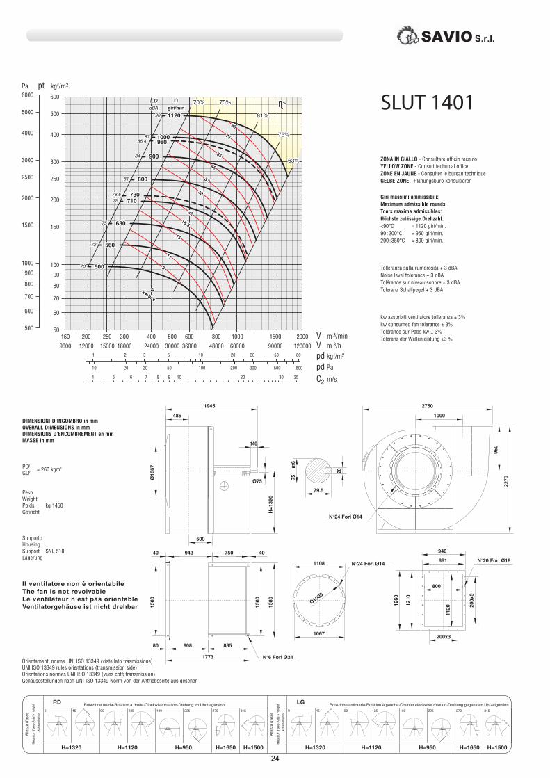
N 16 Prig. M120291
008
2240
800
009
869
708
630
750
0201
200x3
4x002
81
69
6m 56
140
Ø65
0211=H
354
168Ø
808Ø
908
600
0721
0021
35
861
700N 6 Fori Ø21
384
0021
35 738
70 638
1408
N 18 Fori Ø14N 16 Fori Ø14
1565
%ngiri/min
1400
1250
1120
1000
900
800
710
630
55
54
73
03
22
5.81
51
11
9
5.7
ssa/wk
P
980
%ngiri/min
1400
1250
1120
1000
900
800
710
630
980
55
54
73
03
22
5.81
51
11
9
5.7
ssa/wk
P
Il ventilatore non è orientabileThe fan is not revolvableLe ventilateur n’est pas orientableVentilatorgehäuse ist nicht drehbar
LGRD
H=1320H=800H=1120H=800 H=1320H=1120
SAVIO S.r.l.
22

038
365
2470
0802
N 16 Fori Ø14
900
02
4x0020001
0211
7701
1008
958
830
200x3
710
785
74.5
6m 07Ø70
0521=H
140
859Ø
0231
40670
0041
785N 6 Fori Ø24
833
0231
40
71880
1583
434
Ø809
N 18 Fori Ø14N 16 Fori Ø14
1745
wk
ssa/P
57
55
54
73
03
22
5.81
51
11
5.7
9
ngiri/min
1250
1120
1000
900
800
710
630
560
%
980
%n
giri/min
1250
1120
1000
900
800
710
630
560
980
wk
ssa/P
57
55
54
73
03
22
5.81
51
11
5.7
9
Il ventilatore non è orientabileThe fan is not revolvableLe ventilateur n’est pas orientableVentilatorgehäuse ist nicht drehbar
LGRD
H=1500H=830H=1250H=830 H=1500H=1250
SAVIO S.r.l.
23
N 24 Fori Ø14
2750
1000
0722
059
02
79.5
5x002
940
881
800
200x3
0211
0621
1108
8001Ø
1067
0121
140
1945
6m 57
0231=H
Ø75
485
7601Ø
0051
0851
40750
N 6 Fori Ø241773
885
943
0051
40
80880
500
N 20 Fori Ø18N 24 Fori Ø14
%ngiri/min
1120
1000
900
800
710
630
560
500
ssa/wk P
09
57
55
54
73
03
22
5.81
51
9
11
980
730
%ngiri/min
1120
1000
900
800
710
630
560
500
980
730
ssa/wk P
09
57
55
54
73
03
22
5.81
51
9
11
Il ventilatore non è orientabileThe fan is not revolvableLe ventilateur n’est pas orientableVentilatorgehäuse ist nicht drehbar
LGRD
H=950H=1120 H=1650 H=1500H=1320 H=950H=1120 H=1650 H=1500H=1320
SAVIO S.r.l.
24

N 24 Fori Ø140601
0652
1120
3070
22
85
978
900
1040
0521
200x4
7431
0931
6x002
1250
1200
0311Ø
170
2130
6m 08
0051=H
Ø80
550
0021Ø
40
544
800
0071
0871
1918
930
40
0071
80
1038
908
N 6 Fori Ø24
N 24 Fori Ø14 N 24 Fori Ø18
ssa/wk P
231
011
09
57
55
54
73
03
22
51
5.81
ngiri/min
1000
900
800
710
630
560
500
450
%
990
740
%ngiri/min
1000
900
800
710
630
560
500
450
990
740
ssa/wk P
231
011
09
57
55
54
73
03
22
51
5.81
Il ventilatore non è orientabileThe fan is not revolvableLe ventilateur n’est pas orientableVentilatorgehäuse ist nicht drehbar
LGRD
H=1060H=1250 H=1850 H=1600H=1500 H=1060H=1250 H=1850 H=1600H=1500
SAVIO S.r.l.
25

3425
1220
0092
0521
N 8 Fori Ø28
0091
0081
0081
2205
10951010100
50900120550
170
90
95
52
6m 09
2390
1337
N 24 Fori Ø141380
Ø1260
650
0561=H
515
7331Ø
6x002
N 24 Fori Ø18
1000
200x4
0041
1051
0651
1087
1160
N 24 Fori Ø14
ssa/wk
P
061
231
011
09
57
55
54
73
03
5.81
22
ngiri/min
900
800
710
630
560
500
450
400
%
740
590
%ngiri/min
900
800
710
630
560
500
450
400
740
590
ssa/wk
P
061
231
011
09
57
55
54
73
03
5.81
22
Il ventilatore non è orientabileThe fan is not revolvableLe ventilateur n’est pas orientableVentilatorgehäuse ist nicht drehbar
LGRD
H=1250H=1400 H=2000 H=1800H=1650 H=1250H=1400 H=2000 H=1800H=1650
SAVIO S.r.l.
26

3700
635
190
100
0581=H
2500
0513
1941Ø
1300
0031
575
106
82
6m 001
N 8 Fori Ø28
N 24 Fori Ø161540
1491
0241Ø
125050
2300
100 1130
0002
950 50
0002
0012
1070
0061
N 28 Fori Ø22
7x002
3861
0671
1220
1280
200x5
1120
N 24 Fori Ø16
%
800
710
630
560
500
450
400
ngiri/min
350
052
002
061
231
011
09
57
55
54
73
03
515.81
ssa/wk
P
22
740
590
%
800
710
630
560
500
450
400
ngiri/min
350
740
590
052
002
061
231
011
09
57
55
54
73
03
515.81
ssa/wk
P
22
Il ventilatore non è orientabileThe fan is not revolvableLe ventilateur n’est pas orientableVentilatorgehäuse ist nicht drehbar
LGRD
H=1300H=1500 H=2200 H=1900H=1850 H=1300H=1500 H=2200 H=1900H=1850
SAVIO S.r.l.
27
X
G
X
E
B (B)
I (I)
F
2X+F
+G
N.6 Fori Ø D (D)
XI (I)
G
N.8 Fori Ø
X
E
I (I)
B (B)
H
2X+F
+G
C L
F
H
M
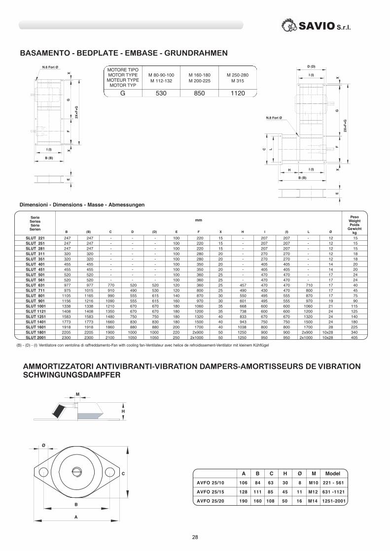
A B C H Ø M Model
AVFO 25/10 106 84 63 30 8 M10 221 - 561
AVFO 25/15 128 111 85 45 11 M12 631 -1121
AVFO 25/20 190 160 108 50 16 M14 1251-2001
Ø
B
A
AMMORTIZZATORI ANTIVIBRANTI-VIBRATION DAMPERS-AMORTISSEURS DE VIBRATION SCHWINGUNGSDAMPFER
C
BASAMENTO - BEDPLATE - EMBASE - GRUNDRAHMEN
SerieSeriesSérie
Serien
PesoWeightPoids
GewichtkgC(B)B D (D) E F X H I (I) L Ø
SLUT 221SLUT 251SLUT 281SLUT 311SLUT 351SLUT 401SLUT 451SLUT 501SLUT 561SLUT 631SLUT 711SLUT 801SLUT 901SLUT 1001SLUT 1121SLUT 1251SLUT 1401SLUT 1601SLUT 1801SLUT 2001
mm
Dimensioni - Dimensions - Masse - Abmessungen
SAVIO S.r.l.
28

a b a1 b1 a2 b2 t H n° Ø kg
TipoTypeTypTipo
PesoWeightPoids
Gewicht
90 x 63
100 x 71
112 x 80
125 x 90
140 x 100
160 x 112
180 x 125
200 x 140
224 x 160
250 x 180
280 x 200
315 x 224
355 x 250
400 x 280
450 x 315
500 x 355
560 x 400
630 x 450
710 x 500
800 x 560
900 x 630
1000 x 710
1120 x 800
1250 x 900
1400 x 1000
1600 x 1120
1800 x 1250
2000 x 1400
mm Fori
Giunti antivibranti in aspirazioneVibration-damping couplings intake-endJoints antivibratoires aspirationElastische Verbindungen saugseitig
D D1 D2 H n° Ø kg
TipoTypeTypTipo
PesoWeightPoids
Gewicht
140
160
180
200
224
250
280
315
355
400
450
500
560
630
710
800
900
1000
1120
1250
1400
1600
1800
2000
mm Fori
Giunti antivibranti in mandataVibration-damping couplings outflow-endJoints antivibratoires refoulementElastische Verbindungen drückseitig
t
a2a1
t
ta
tt
b1
H
b
b2
N Fori Ø
H
1D
D
D2
N Fori Ø
SAVIO S.r.l.
29

Valvola a farfallaThrottle valveSoupape rondeDrosselklappe Rund
DIMENSIONI D’INGOMBRO in mmOVERALL DIMENSIONS in mmDIMENSIONS D’ENCOMBREMENT en mmMASSE in mm
f
e
D1
3D
2D
Ød
N. Fori Ø
H
Rete di protezioneProtection NetGrille de protectionSchutzgitter
1D
D2
S
StrebenN. EtresillonsN. StrutsN. Bracci
Tipo - TypeTyp - Tipo
D1 D2 S N° Bracci N° StrutsN°Etresillons Streben
RP 125RP 140RP 160RP 180RP 200RP 224RP 250RP 280RP 315RP 355RP 400RP 450RP 500RP 560RP 630RP 710RP 800RP 900RP 1000RP 1120RP 1250RP 1400RP 1600RP 1800RP 2000
D1 D2 D3 d e f H kgn° …fori Ø
TipoTypeTypTipo
PesoWeightPoids
Gewicht
140
160
180
200
224
250
280
315
355
400
450
500
560
630
710
800
900
1000
1120
SAVIO S.r.l.
30

Regolatori di portata rettangolari sulla mandata
Rectangular flow regulators, outflow end
Régulateurs de débit rectangulaires sur le refoulement
Rechteckige Durchflußregler der Förderleistund
DIMENSIONI D’INGOMBRO in mmOVERALL DIMENSIONS in mmDIMENSIONS D’ENCOMBREMENT en mmMASSE in mm
H
ØD4ØD1ØD3
2D
N. Fori Ø
90 x 63
100 x 71
112 x 80
125 x 90
140 x 100
160 x 112
180 x 125
200 x 140
224 x 160
250 x 180
280 x 200
315 x 224
355 x 250
400 x 280
450 x 315
500 x 355
560 x 400
630 x 450
710 x 500
800 x 560
900 x 630
1000 x 710
1120 x 800
1250 x 900
1400 x 1000
1600 x 1120
1800 x 1250
2000 x 1400
a b a1 b1 a2 b2 H t n° fori Ø kg
TipoTypeTypTipo
PesoWeightPoids
Gewicht
Regolatori di portata circolari “DAPÒ”Circular “DAPÒ” flow regulatorsRégulateurs de débit circulaires “DAPÒ”Runde Durchflußregler “DAPÒ”
D1 D2 D3 D4 H n° fori Ø kg
TipoTypeTypTipo
PesoWeightPoids
Gewicht
DIMENSIONI D’INGOMBRO in mmOVERALL DIMENSIONS in mmDIMENSIONS D’ENCOMBREMENT en mmMASSE in mm
280
315
355
400
450
500
560
630
710
800
900
1000
1120
1250
1400
1600
1800
2000
a1
t
t
a2 a
b2
b
b1
t H
N. Fori Ø
SAVIO S.r.l.
31

Via Reggio Calabria,13 – Cascine Vica Rivoli (TO) Italia Tel: (+39) 011. 959.16.01 Fax: (+39) 011. 959.29.62E-mail : [email protected] http:// www.savioclima.it
Ed. Febbraio 2011