indice - iesasl.e.telefonica.net
TRANSCRIPT

INDICE INDEX
Página / Page
- Datos Técnicos / Technical Specifications ……….…………………………. …………….3- 9
- Bandeja Perforada (Serie BP) / Perforated tray (BP Series) ……………….. …………..11- 19
- Bandeja Escalera (Serie BEL) / Ladder tray (BEL Series) …………………. …………...20- 28
- Bandeja Escalera (Serie BE) / Ladder tray (BE Series) ……………………………………...29- 37
- Canal Cerrado (Serie C) / Closed Channel (C Series) ………………………………………. 38
- Soportes (Serie SE) / Supports (SE Series) …………………………………. …………….39- 47
- Railes (Serie RL) / Rails (RL Series) …………………………………………. …………..48- 49
IESA,S.L.___________________________________________________________________________ 2

INFORME SOBRE EL ENSAYO DE CUALIFICACION SISMICA DE BANDEJAS Y ACCESORIOSIESA CON DESTINO AL MONTAJE EN CENTRALES NUCLEARES.
REPORT ON THE SEISMIC RATING TEST OF VARIOUS TYPE OF TRAYS AND ACCESSORIESFOR ASSEMBLY IN NUCLEAR STATIONS
Una muestra suficientemente amplia de los materiales que componen este catálogo, han sido sometidosa las pruebas de cualificación sísmica que establece el IEE en su norma 34-1975 para determinar contoda precisión el comportamiento mecánico de nuestras bandejas y soportes para las mismas, en lascondiciones más difíciles.
A large sample of the materials includes in this catalogue, have been subjected to various seismic testsin accordance with IEE Standard number 34-1975 to determinate precisely the mechanical behaviour orour trays and supports in the most difficult conditions.
Las bandejas fueron colocadas sobre una plataforma de ensayos (Foto 1) de acción biaxial simultánea,impulsada por un actuador de frecuencia y aceleración variables, en el cual el movimineto vertical es igual al horizontal actuando ambos simultáneamente.
Trays were placed on the test platform (Photography nº 1) with simultaneous biaxial action and impulsedby one function of frequency and variable acceleration for both directions (vertical and horizontal).
Se determinan las curvas del factor de amplificación y las frecuencias de resonancia (11Hz en direcciónvertical en ambas posiciones, 25 Hz para la posición XZ y 11,2 Hz para la posición YZ).
The curves have provided the values of the amplification factor and the resonance frequencies (11Hz in avertical direction in both positions, 25 Hz for position XZ and 11,2 Hz for position YZ).
Estos datos corresponden a las bandejas serie BEL; la bandeja perforada presenta una frecuencia deresonancia de 7 Hz para la dirección vertical y de 47 Hz en dirección horizontal.
These data correspond to BEL series trays. Perforated tray exhibits a resonance frequency of 7 Hz in a vertical direction and 47 Hz in horizontal direction.
Posteriormente se realizan los ensayos con onda senoidal contínua a las frecuencias de resonancia delas bandejas, para determinar los amortiguamientos que oscilan entre 3,1 y 7,5 en la dirección horizontaly 2,3 y 4,7 para la dirección vertical.
Subsequently, the sequence of test is carried out with the trays with a continuous sinusoidal wave at the resonance frequencies, for determining the damping values. The values range between 3,1 and 7,for the horizontal direction, and between 2,3 and 4,7 for the vertical direction.
IESA,S.L.___________________________________________________________________________ 3
De otros ensayos con multifrecuencia de banda ancha, realizados en las dos direcciones principales dela plataforma se obtuvieron los TRS para los amortiguamientos del 2,5, 5 y 10 % (Fig. B) que cubren la curva obtenida de la norma 344-1975 (Fig. A).
From other test seismic rating test performed with a broad band multifrequency for both directions of thetest platform, we have obtained the TRS for the accelerometer, drown for 2,5 and 5 and 10 % (Fig. B) damping, according to 344-1975 Standard (Fig. A).
Todas estas pruebas han sido realizadas lastrando las bandejas con cables hasta un peso de 150 Kgs.por bandeja.
All these test have been carried out loading trays qith cables up to 150 Kgs.per tray.
Simultáneamente se han medido los esfuerzos mecánicos de la estructura, a flexión, torsión y cizalladura, comportamiento de las uniones de travesaños a la largueros, etc.
Simultaneously we have measured the mechanical efforts of the structure, flexión, twisting and clippingbehaviour of unions of transoms to jambs, etc.
Los resultados en todos los ensayos, que constan en la documentación que de ellos poseemos, es quetodos los materiales han soportado las pruebas sin que se detecte ninguna deformación estructural nirotura, ni cualquier otra anomalía.
The results of the essays indicate that all the material have supported all the test, detecting neitherstructural deformations nor breaks or any anomaly.
La conclusión es que nuestros fabricados han superado las pruebas que establece el IEE para la cualificación sísmica y que son aptos para su montaje en instalaciones que requieren esta condición.
The conclusion is that our products have surpassed all the proofs established by IEE for the seismicqualification and they are suitable for assembly on installations in this conditions.
Aportando estos datos creemos haber contribuido a un conocimiento más en profundidad de nuestrafabricación por parte de nuestros clientes.
We hope our clients understanding in great detail our manufacture, with the documentation remitted.
Fig. A Fig. B
IESA,S.L.___________________________________________________________________________ 4
A-25%
D 5%
ZPA
C-10%
2,5%
5%
10%
E
MATERIALES / MATERIALS
Las bandejas IESA están construidas con acero laminado en frío de primera calidad. Bajo demanda se pueden fabricar en otros materiales, como aluminio, fibras especiales, PVC, etc.
The raw material for the manufacture of tray is top quality sheet cold steel. Upon request, other materials(aluminium, special fibres, PVC, etc.) are avaible.
La bandejas perforadas y cerradas se construyen en acero laminado en frío, que posteriormente se protege con alguno de los sistemas abajo descritos, o de chapa laminada en frío y galvanizada en bandapor el procedimiento SENDZIMIR.
The perforated trays and sheet cold steel made and coated with one of the systems set up below, or sheet plate galvanized by SENDZIMIR procedure.
La tornillería es de acero, y en casos especiales en acero inoxidable.
The screws are steel made, and in special cases stainless steel.
REVESTIMIENTOS / COATING
Los revestimientos que para este tipo de material tenemos standarizados son los siguientes:
The coating for this type of material are as follows:
GALVANIZADO POR INMERSION EN CALIENTE / HOT DIP GALVANIZED
Este procedimiento de recubrir el acero consiste en la introducción de las piezas en unacuba llena de zinc fundido.
This metallurgical process to coat steel or iron with zinc consists of dying the pieces in onebarrel full of hot melted zinc.
Previamente es necesario decapar con ácidos para eliminar los óxidos superficiales.
Previously, it is necessary to scrape with acids to dispose of the superficial oxides.
La superficie de las bandejas queda totalmente cubierta por una capa de zinc de un espesor que oscila entre 70 y 120 micras. Las características de este revestimiento frentea la corrosión son sobradamente conocidas: no se produce oxidación en tanto quede sobrela superficie de la pieza recubrimiento de zinc.
The surface of the trays will be zinc-plate with a thicknees between 70 and 120 microns. Thecharacteristics of this type of coating on corrosion are well know: there is not oxidation until zinc does not disappear.
RECUBRIMIENTO DE RESINA EPOXY-POLIESTER / COATING OF EPOXY POLYESTER RESIN
Consiste en proyectar electrostáticamente sobre la superficie de las piezas previamentepreparadas, tras un proceso especial, unas resinas de epoxy en partículas de diversomicrage.
It consists of projecting electro statically some resins of epoxy on the surface of the piecethat piece that is prepared previously.
La protección es de una gran resistencia mecánica, y muy eficaz contra la corrosiónincluso en ambientes húmedos o salinos. La superficie resultante es muy adecuada para elcontácto con los cables por no presentar elementos que puedan dañarlo y proporcionaademás un buen aislamiento eléctrico.
The protection has a grat mechanical resistance, and it is effective against the corrosion,even in damp or saline environmet.The resulting surface is suitable for the contact with thecables because it does not elements that can spoil it and provides a good electricalinsulation as well.
IESA,S.L.___________________________________________________________________________ 5
Los espesores que se obtienen varían de 40 a 140 micras. Los colores más usuales sonel gris y el rojo óxido.
The thickness goes to up 40 microns. The common colours are grey and red oxide.
RECUBRIMIENTO CON LEVASINT / COATING WITH LEVASINT
Se sumergen las piezas en un baño fluidificado de polvo de LEVASINT, previo tratamientosuperficial con chorro de arena. Proporciona un revestimiento eficaz a la corrosión en ambientes muy húmedos, salinos y químicos. Es aislante y deja una superficie muy adecuada para el tendido de cables. Los espesores varían de 0,2 a 0,4 mm.
The pieces are dyed in fluidized plating dust, after a superficial treatment with a sand jet.It provides an effective coating against corrosion in damp,chemical and saline environmentsIt is insulating and allows a suitable surface for electrical installation. Thickness is between0,2 to 0,4 mm.
RECUBRIMIENTO CON LEVASINT Y ELECTROCINCADO / COATING WITH LEVASINT ELECTROLYTIC ZINC
Idem que el tratamiento anterior, pero con previo electrocincado por deposición en cubaelectrolítica de 15 a 20 micras de espesor, aumenta la protección de las bandejas. No esposible su aplicación en la serie BE; por imperativo del tamaño de las piezas.
Idem the previous treatment, but it is realized after one electrolytic zinc by deposition in anelectrolytic barrel of 15 to 20 microns of thickness that increases the protection of the trays.It is not possible in BE series because of the length of the pieces.
RECUBRIMIENTO ELECTROCINCADO / COATING ELECTROLYTIC ZINC
Consiste en la introducción de las piezas en una cuba electrolítica, donde el zinc se deposita en un espesor de 15 a 20 micras.
It consists of the introduction of the pieces in an electrolytic barrel, where the zinc isdeposited with a thickness between 15 to 20 microns.
IESA,S.L.___________________________________________________________________________ 6
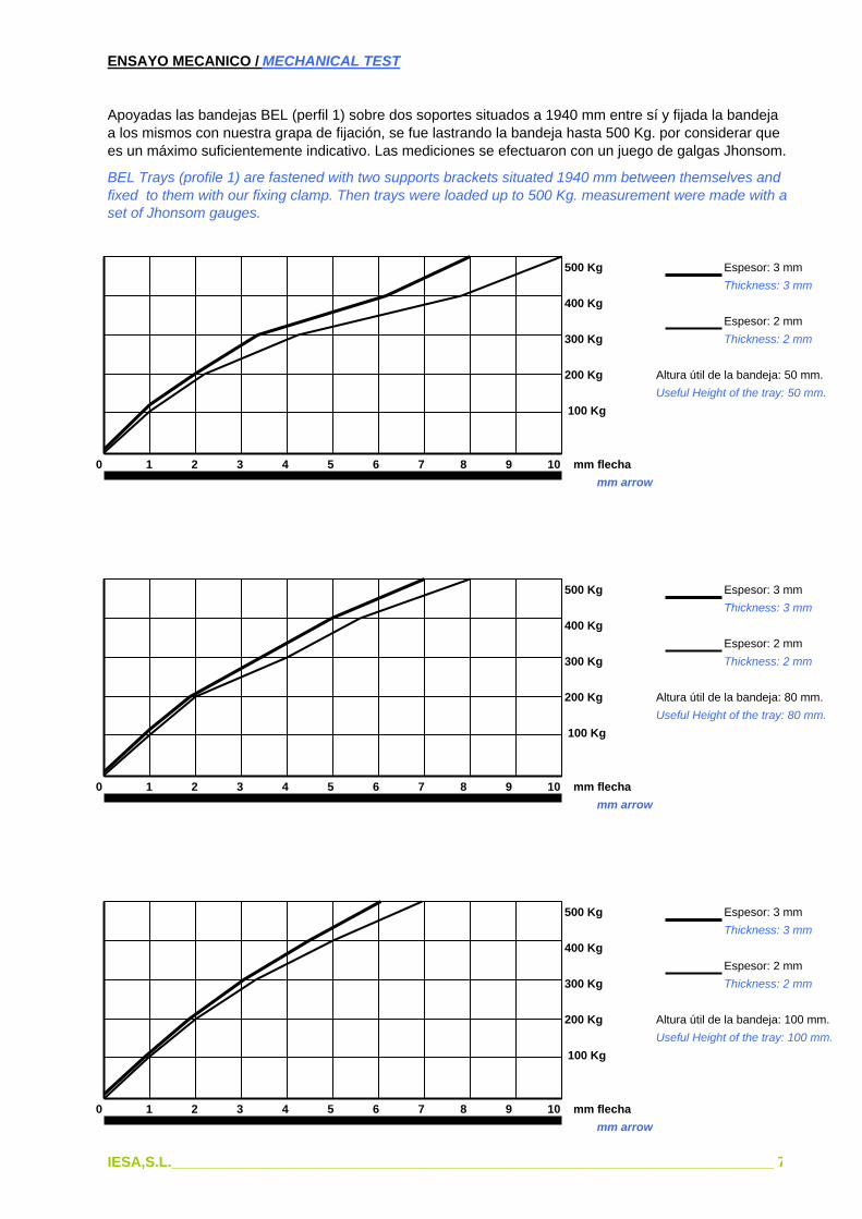
ENSAYO MECANICO / MECHANICAL TEST
Apoyadas las bandejas BEL (perfil 1) sobre dos soportes situados a 1940 mm entre sí y fijada la bandejaa los mismos con nuestra grapa de fijación, se fue lastrando la bandeja hasta 500 Kg. por considerar quees un máximo suficientemente indicativo. Las mediciones se efectuaron con un juego de galgas Jhonsom.
BEL Trays (profile 1) are fastened with two supports brackets situated 1940 mm between themselves andfixed to them with our fixing clamp. Then trays were loaded up to 500 Kg. measurement were made with aset of Jhonsom gauges.
500 Kg Espesor: 3 mm Thickness: 3 mm
400 Kg Espesor: 2 mm
300 Kg Thickness: 2 mm
200 Kg Altura útil de la bandeja: 50 mm.Useful Height of the tray: 50 mm.
100 Kg
0 1 2 3 4 5 6 7 8 9 10 mm flecha mm arrow
500 Kg Espesor: 3 mm Thickness: 3 mm
400 Kg Espesor: 2 mm
300 Kg Thickness: 2 mm
200 Kg Altura útil de la bandeja: 80 mm.Useful Height of the tray: 80 mm.
100 Kg
0 1 2 3 4 5 6 7 8 9 10 mm flecha mm arrow
500 Kg Espesor: 3 mm Thickness: 3 mm
400 Kg Espesor: 2 mm
300 Kg Thickness: 2 mm
200 Kg Altura útil de la bandeja: 100 mm.Useful Height of the tray: 100 mm.
100 Kg
0 1 2 3 4 5 6 7 8 9 10 mm flecha mm arrow
IESA,S.L.___________________________________________________________________________ 7

ENSAYO MECANICO / MATERIALS
NOTA: Para las bandejas de serie BE, representadas en esta foto (Planta de Alúmina Española, SanCiprián, Lugo), la disposición del tendido eléctrico, así como la capacidad de la canalización no es posibleestandarizarla, por ser material destinado a instalaciones especiales; razón por la cual no hemos publicadoel gráfico de capacidad de cables.
NOTE : The electrical installation of BE series trays ( Photograph above: "Aluminia Española Plant,San Ciprian - Lugo - Spain ) and its capacity of channelling, cannot be standardized, because it is amaterial for special installations. For this reason, we have not published the graphic of cables capacity.
700 Kg
600 Kg
500 KgAltura útil de la bandeja: 80 mm.
400 Kg Useful Height of the tray: 100 mm.
300 KgAncho de la bandeja: 600 mm.
200 Kg Width of the tray: 600 mm.
100 Kg
0 5 10 15 20 25 30 35 40 45 mm flecha mm arrow
Este gráfico corresponde al comportamiento de una bandeja de escalera serie BE, apoyada en dos soportesdistantes entre sí 5.900 mm.
This graphic corresponds to the behaviour of one BE series tray supported in two supports brackets situated5.900 mm between them selves.
IESA,S.L.___________________________________________________________________________ 8

CAPACIDAD DE CABLES DE LAS BANDEJAS Serie BEL /CAPACITY OF THE SERIES BEL TRAYS
Es recomendable no agotar las posibilidades de la capacidad de la bandeja para facilitar los trabajos en el montaje del tendido eléctrico.It is recommended not to exhaust the possibilities of the capacity of the tray to facilitate the works in theelectrical installations.
ANCHURA DE CANAL: 100 mm ANCHURA DE CANAL: 200 mm. Width of channel: 100 mm Width of channel: 200 mm.
Sección cable Peso Alt. Libre 50 Alt. Libre 80 Alt. Libre 100 Alt. Libre 50 Alt. Libre 80 Alt. Libre 100 Section cable Weight Heig. Free 50 Heig. Free 80 Heig. Free 100 Heig. Free 50 Heig. Free 80 Heig. Free 100 mm Kg/m Nº cables Kg/m Nº cables Kg/m Nº cables Kg/m Nº cables Kg/m Nº cables Kg/m Nº cables Kg/m 1,5 13 0,22 24 5,2 56 12,3 70 15,4 43 9,4 105 23,1 131 28,8 2,5 14 0,30 21 6,3 49 14,7 61 18,3 40 12,0 96 28,8 120 36,0 4 16 0,40 18 7,2 36 14,4 45 18,0 34 13,6 72 28,8 90 36,0 6 17 0,51 15 7,6 25 12,7 31 15,8 32 16,3 55 28,0 68 34,6 10 19 0,71 10 7,1 25 17,7 31 22,0 20 14,2 50 35,5 62 44,0 16 22 1,05 8 8,4 15 15,7 18 18,9 16 16,8 43 45,1 53 55,6 25 27 1,60 6 9,6 8 14,4 10 16,0 13 20,8 23 41,6 28 44,8 35 29 2,10 6 12,6 9 18,9 11 23,1 12 25,2 18 37,8 22 46,2 50 34 2,94 4 11,7 6 17,6 7 20,5 7 20,5 15 44,1 18 52,9 70 38 3,87 2 11,6 5 19,3 6 23,2 7 27,0 14 54,1 17 65,7 95 44 5,18 2 10,3 4 20,7 5 25,9 4 20,7 8 41,4 10 51,8 120 47 6,73 2 12,6 3 18,9 3 18,9 3 18,9 8 50,6 10 67,3 150 52 7,79 1 7,8 2 15,5 2 15,5 3 23,3 9 70,1 11 85,6 185 59 9,69 1 9,7 2 19,4 2 19,4 3 29,0 6 58,1 7 67,8 240 71 13,00 1 13,0 1 13,0 1 13,0 2 26,0 2 26,0 2 26,0
ANCHURA DE CANAL: 300 mm ANCHURA DE CANAL: 400 mm. Width of channel: 300 mm Width of channel: 400 mm.
Sección cable Peso Alt. Libre 50 Alt. Libre 80 Alt. Libre 100 Alt. Libre 50 Alt. Libre 80 Alt. Libre 100 Section cable Weight Heig. Free 50 Heig. Free 80 Heig. Free 100 Heig. Free 50 Heig. Free 80 Heig. Free 100 mm Kg/m Nº cables Kg/m Nº cables Kg/m Nº cables Kg/m Nº cables Kg/m Nº cables Kg/m Nº cables Kg/m 1,5 13 0,22 67 14,7 182 40,0 227 49,9 89 19,5 239 52,5 298 65,5 2,5 14 0,30 61 18,3 145 43,5 181 54,3 83 24,9 195 58,5 243 72,9 4 16 0,40 52 20,8 107 42,8 133 53,2 72 28,8 144 57,6 180 72,0 6 17 0,51 50 25,5 100 51,0 125 63,7 68 34,8 137 69,8 171 87,2 10 19 0,71 29 20,5 74 52,5 92 65,3 40 28,4 100 71,0 125 88,7 16 22 1,05 25 26,2 50 52,5 62 65,1 35 36,7 89 93,4 111 116,5 25 27 1,60 20 32,0 42 67,2 52 83,2 27 43,2 56 89,6 70 112,0 35 29 2,10 18 37,8 38 79,8 47 98,7 25 52,5 52 109,2 65 136,5 50 34 2,94 8 23,5 24 70,5 30 88,2 11 32,3 33 97,0 41 120,5 70 38 3,87 7 27,0 19 73,5 23 89,0 9 34,8 29 112,2 36 139,3 95 44 5,18 4 20,7 17 88,0 21 108,7 9 46,6 17 88,0 21 108,7 120 47 6,73 4 25,3 12 75,9 15 100,9 8 50,6 16 101,2 20 134,6 150 52 7,79 4 31,1 9 70,1 11 85,6 6 46,7 14 116,8 17 132,4 185 59 9,69 4 38,7 9 87,2 11 106,5 5 48,4 12 116,2 15 145,3 240 71 13,00 3 39,0 7 91,0 8 104,0 3 39,0 10 130,0 12 156,0
ANCHURA DE CANAL: 500 mm ANCHURA DE CANAL: 600 mm. Width of channel: 500 mm Width of channel: 600 mm.
Sección cable Peso Alt. Libre 50 Alt. Libre 80 Alt. Libre 100 Alt. Libre 50 Alt. Libre 80 Alt. Libre 100 Section cable Weight Heig. Free 50 Heig. Free 80 Heig. Free 100 Heig. Free 50 Heig. Free 80 Heig. Free 100 mm Kg/m Nº cables Kg/m Nº cables Kg/m Nº cables Kg/m Nº cables Kg/m Nº cables Kg/m Nº cables Kg/m 1,5 13 0,22 112 24,6 302 66,4 377 82,9 135 29,7 313 68,8 391 86,0 2,5 14 0,30 103 30,9 243 72,9 303 90,9 125 37,5 293 87,9 366 109,8 4 16 0,40 90 36,0 180 72,0 225 90,0 110 44,0 221 88,4 276 110,4 6 17 0,51 86 43,0 173 88,2 216 110,0 104 53,0 209 106,5 261 133,1 10 19 0,71 52 36,9 129 91,5 161 114,3 62 44,0 155 110,0 193 137,0 16 22 1,05 43 45,1 110 115,5 137 143,8 54 56,7 135 147,7 168 176,0 25 27 1,60 35 56,0 71 113,6 88 140,8 43 68,8 88 140,8 110 176,0 35 29 2,10 34 71,4 51 107,1 63 132,3 40 84,0 80 168,0 100 210,0 50 34 2,94 14 41,6 42 123,4 52 152,8 17 49,9 50 147,0 62 182,0 70 38 3,87 13 50,3 38 147,0 47 181,8 15 58,0 44 170,2 55 212,0 95 44 5,18 10 51,8 22 113,9 27 139,8 13 67,3 39 202,0 48 248,0 120 47 6,73 9 56,9 20 126,6 25 168,2 12 75,9 24 151,9 30 201,9 150 52 7,79 8 62,3 18 140,2 22 171,3 10 77,9 22 171,3 27 210,3 185 59 9,69 7 67,8 16 155,0 20 193,8 9 87,2 20 193,8 25 242,2 240 71 13,00 4 52,0 11 143,0 13 169,0 6 78,0 14 182,0 17 221,0

PESOS DE BANDEJAS / WEIGHTS
BANDEJA ESCALERA LIGERA Serie BEL / LIGHT LADDER TRAY BEL Series
Perfil Nº 1 Perfil Nº 2Profile Nº 1 Profile Nº 2
Ancho Kg/m Ancho Kg/mWidth Kg/m Width Kg/m
600 8,1 600 9,1500 7,6 500 8,6400 7,0 400 8,0300 6,6 300 7,6200 5,0 200 5,5100 4,3 100 4,9
Los pesos están tomados de la bandeja con altura libre de 80 mm.
These weights correspond to 80 mm free height tray.
BANDEJA ESCALERA PESADA Serie BE / HEAVY LADDER TRAY BE Series
100/500 100/300 150/300Ancho Kg/mWidth Kg/m
910 17,3 19,9 23,9600 15,9 17,6 21,5460 15,2 16,6 20,5230 14,2 14,9 18,8
BANDEJA PERFORADA Serie BP / PERFORATEDTRAY BP Series
ESPESORES / THICKNESS
0,8 1 1,2 1,5 2 2,5Ancho Kg/mWidth Kg/m
50 0,55 0,68 0,82 1,03 1,37 1,70100 0,85 1,06 1,28 1,60 2,13 2,60200 1,48 1,85 2,22 2,77 3,70 4,60400 2,73 3,42 4,10 4,79 6,38 8,50
IESA,S.L.___________________________________________________________________________ 10

BANDEJA PERFORADA Serie BP / PERFORATED TRAY BP Series
INDICAR ESPESOR Y ACABADOINDICATE THICKNESS AND FINISH
Nota: Se puede fabricar en otros anchos y alturas de ala
Note: it can be manufactured in others widths and heights of wing
Espesores: 1,5 - 2 - 2,5 - 3 mmThickness : 1,5 - 2 - 2,5 - 3 mm
REFERENCIAREFERENCE BP-50 BP-100 BP-150 BP-200 BP-250 BP-300 BP-400 BP-500 BP-600
A 50 100 150 200 250 300 400 500 600B 15 15 25 25 25 50 50 50 50
IESA,S.L.___________________________________________________________________________ 11
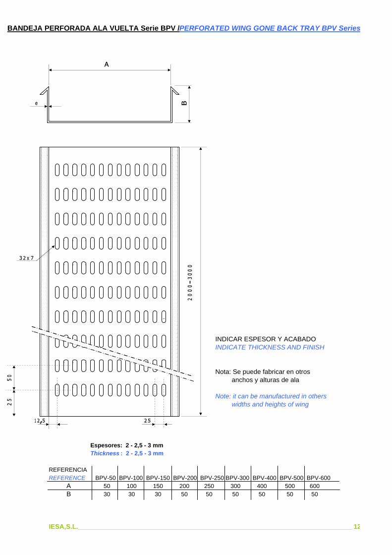
BANDEJA PERFORADA ALA VUELTA Serie BPV /PERFORATED WING GONE BACK TRAY BPV Series
INDICAR ESPESOR Y ACABADOINDICATE THICKNESS AND FINISH
Nota: Se puede fabricar en otros anchos y alturas de ala
Note: it can be manufactured in others widths and heights of wing
Espesores: 2 - 2,5 - 3 mmThickness : 2 - 2,5 - 3 mm
REFERENCIAREFERENCE BPV-50 BPV-100 BPV-150 BPV-200 BPV-250 BPV-300 BPV-400 BPV-500 BPV-600
A 50 100 150 200 250 300 400 500 600B 30 30 30 50 50 50 50 50 50
IESA,S.L.___________________________________________________________________________ 12

CODO HORIZONTAL 90º Serie CH / HORIZONTAL ELBOW 90º CH Series
INDICAR ESPESOR Y ACABADOINDICATE THICKNESS AND FINISH
Espesores: 1,5 - 2 - 2,5 - 3 mmThickness : 1,5 - 2 - 2,5 - 3 mm
REFERENCIAREFERENCE CH-50 CH-100 CH-150 CH-200 CH-250 CH-300 CH-400 CH-500 CH-600
A 50 100 150 200 250 300 400 500 600B 15-30 15-30 25-30 25-50 25-50 50 50 50 50
IESA,S.L.___________________________________________________________________________ 13
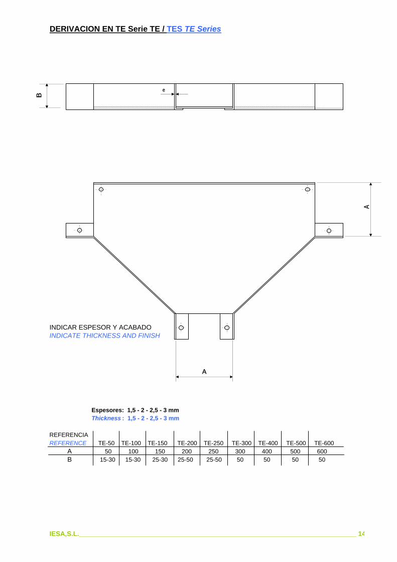
DERIVACION EN TE Serie TE / TES TE Series
INDICAR ESPESOR Y ACABADOINDICATE THICKNESS AND FINISH
Espesores: 1,5 - 2 - 2,5 - 3 mmThickness : 1,5 - 2 - 2,5 - 3 mm
REFERENCIAREFERENCE TE-50 TE-100 TE-150 TE-200 TE-250 TE-300 TE-400 TE-500 TE-600
A 50 100 150 200 250 300 400 500 600B 15-30 15-30 25-30 25-50 25-50 50 50 50 50
IESA,S.L.___________________________________________________________________________ 14

CODO CONVEXO 90º Serie CX / CONVEX ELBOW 90º CX Series
INDICAR ESPESOR Y ACABADOINDICATE THICKNESS AND FINISH
Espesores: 1,5 - 2 - 2,5 - 3 mmThickness : 1,5 - 2 - 2,5 - 3 mm
REFERENCIAREFERENCE CX-50 CX-100 CX-150 CX-200 CX-250 CX-300 CX-400 CX-500 CX-600
A 50 100 150 200 250 300 400 500 600B 15-30 15-30 25-30 25-50 25-50 50 50 50 50
IESA,S.L.___________________________________________________________________________ 15
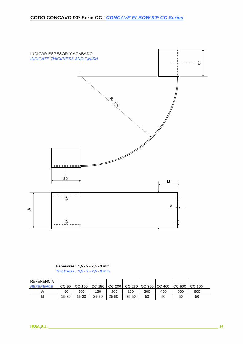
CODO CONCAVO 90º Serie CC / CONCAVE ELBOW 90º CC Series
INDICAR ESPESOR Y ACABADOINDICATE THICKNESS AND FINISH
Espesores: 1,5 - 2 - 2,5 - 3 mmThickness : 1,5 - 2 - 2,5 - 3 mm
REFERENCIAREFERENCE CC-50 CC-100 CC-150 CC-200 CC-250 CC-300 CC-400 CC-500 CC-600
A 50 100 150 200 250 300 400 500 600B 15-30 15-30 25-30 25-50 25-50 50 50 50 50
IESA,S.L.___________________________________________________________________________ 16

DERIVACION EN CRUZ Serie X / CROSS X Series
INDICAR ESPESOR Y ACABADOINDICATE THICKNESS AND FINISH
Espesores: 1,5 - 2 - 2,5 - 3 mmThickness : 1,5 - 2 - 2,5 - 3 mm
REFERENCIAREFERENCE X-50 X-100 X-150 X-200 X-250 X-300 X-400 X-500 X-600
A 50 100 150 200 250 300 400 500 600B 15-30 15-30 25-30 25-50 25-50 50 50 50 50
IESA,S.L.___________________________________________________________________________ 17
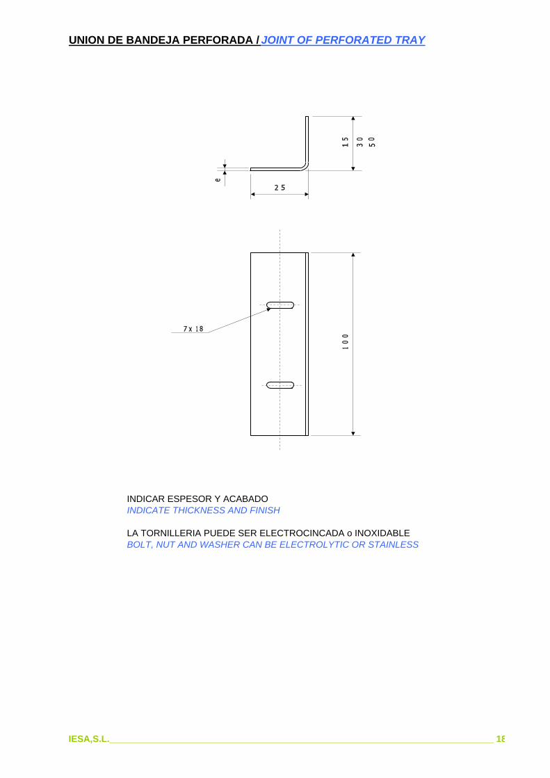
UNION DE BANDEJA PERFORADA / JOINT OF PERFORATED TRAY
INDICAR ESPESOR Y ACABADOINDICATE THICKNESS AND FINISH
LA TORNILLERIA PUEDE SER ELECTROCINCADA o INOXIDABLEBOLT, NUT AND WASHER CAN BE ELECTROLYTIC OR STAINLESS
IESA,S.L.___________________________________________________________________________ 18
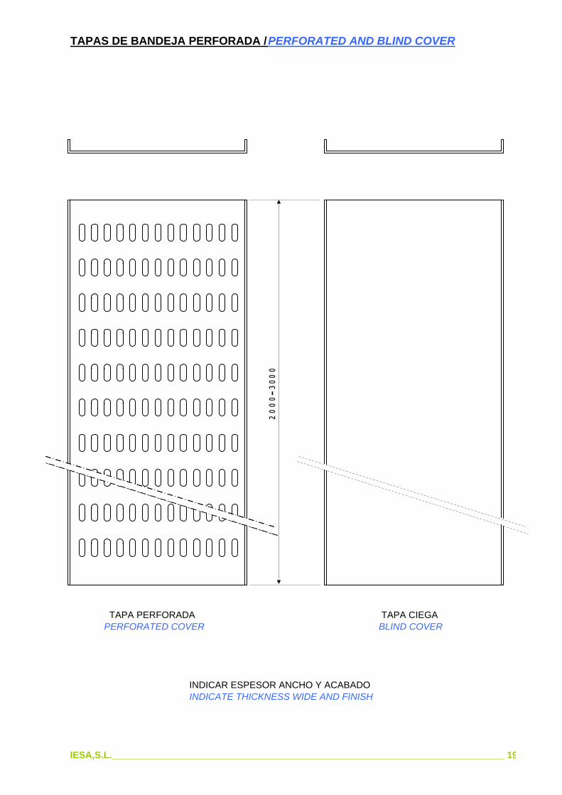
TAPAS DE BANDEJA PERFORADA / PERFORATED AND BLIND COVER
TAPA PERFORADA TAPA CIEGA PERFORATED COVER BLIND COVER
INDICAR ESPESOR ANCHO Y ACABADOINDICATE THICKNESS WIDE AND FINISH
IESA,S.L.___________________________________________________________________________ 19

BANDEJA ESCALERA Serie BEL / LADDER TRAY BEL Series
PERFIL LARGUERO JAMB PROFILE PERFIL TRAVESAÑO
TRANSOM PROFILE
NOTA: La unión de travesaños y largueros se efectúa por soldadura continua CO2, y un electrodo especialcon un coeficiente de alargamiento del 20%, lo que posibilita una estructura firma y elástica al mismo tiempo
NOTE: The joint of transoms and jambs is made by CO2 continuous welding and one special electrode witha 20% of elongation to facilitate both a steady and elastic structure.
REF. BEL 0 BEL 1 BEL 2 BEL 3 BEL 4 BEL 5 BEL 6
A 100 200 300 400 500 600 700B 72 72 72 72 72 72 72
REF. BEL 10 BEL 11 BEL 12 BEL 13 BEL 14 BEL 15 BEL 16
A 100 200 300 400 500 600 700B 102 102 102 102 102 102 102
REF. BEL 20 BEL 21 BEL 22 BEL 23 BEL 24 BEL 25 BEL 26
A 100 200 300 400 500 600 700B 122 122 122 122 122 122 122
La unión entre travesaños y accesorios se efectúa por medio de la placa BE-P
The joint between transoms and fittings is made by one BE-P plate.
Indicar en la referencia el perfil escogido, espesor y el acabado de la bandeja.
Indicate, in the reference, the chosen profile, thickness and the finish of the tray.
IESA,S.L.___________________________________________________________________________ 20
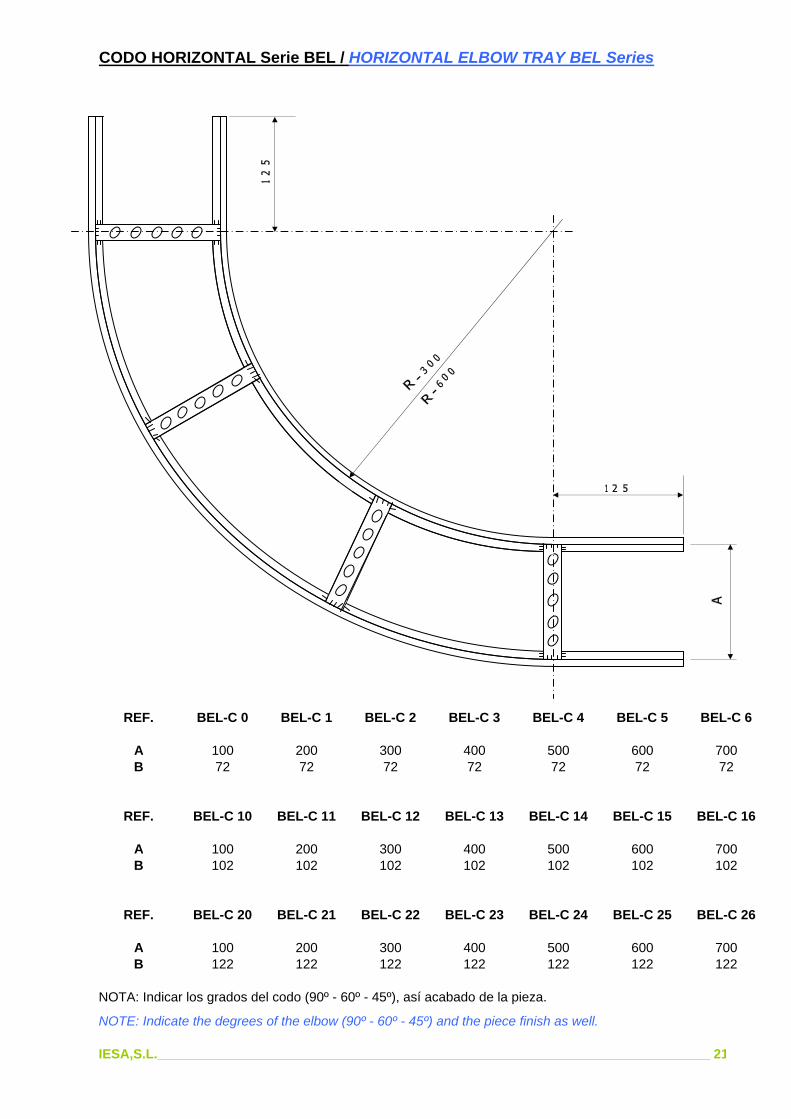
CODO HORIZONTAL Serie BEL / HORIZONTAL ELBOW TRAY BEL Series
REF. BEL-C 0 BEL-C 1 BEL-C 2 BEL-C 3 BEL-C 4 BEL-C 5 BEL-C 6
A 100 200 300 400 500 600 700B 72 72 72 72 72 72 72
REF. BEL-C 10 BEL-C 11 BEL-C 12 BEL-C 13 BEL-C 14 BEL-C 15 BEL-C 16
A 100 200 300 400 500 600 700B 102 102 102 102 102 102 102
REF. BEL-C 20 BEL-C 21 BEL-C 22 BEL-C 23 BEL-C 24 BEL-C 25 BEL-C 26
A 100 200 300 400 500 600 700B 122 122 122 122 122 122 122
NOTA: Indicar los grados del codo (90º - 60º - 45º), así acabado de la pieza.
NOTE: Indicate the degrees of the elbow (90º - 60º - 45º) and the piece finish as well.
IESA,S.L.___________________________________________________________________________ 21

CODO CONCAVO Serie BEL / CONCAVE ELBOW TRAY BEL Series
REF. BEL-CC 0 BEL-CC 1 BEL-CC 2 BEL-CC 3 BEL-CC 4 BEL-CC 5 BEL-CC 6
A 100 200 300 400 500 600 700B 72 72 72 72 72 72 72
REF. BEL-CC 10 BEL-CC 11 BEL-CC 12 BEL-CC 13 BEL-CC 14 BEL-CC 15 BEL-CC 16
A 100 200 300 400 500 600 700B 102 102 102 102 102 102 102
REF. BEL-CC 20 BEL-CC 21 BEL-CC 22 BEL-CC 23 BEL-CC 24 BEL-CC 25 BEL-CC 26
A 100 200 300 400 500 600 700B 122 122 122 122 122 122 122
NOTA: Indicar los grados del codo (90º - 60º - 45º), así acabado de la pieza.
NOTE: Indicate the degrees of the elbow (90º - 60º - 45º) and the piece finish as well.
IESA,S.L.___________________________________________________________________________ 22
0
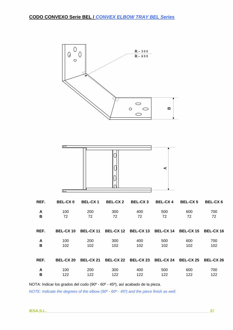
CODO CONVEXO Serie BEL / CONVEX ELBOW TRAY BEL Series
REF. BEL-CX 0 BEL-CX 1 BEL-CX 2 BEL-CX 3 BEL-CX 4 BEL-CX 5 BEL-CX 6
A 100 200 300 400 500 600 700B 72 72 72 72 72 72 72
REF. BEL-CX 10 BEL-CX 11 BEL-CX 12 BEL-CX 13 BEL-CX 14 BEL-CX 15 BEL-CX 16
A 100 200 300 400 500 600 700B 102 102 102 102 102 102 102
REF. BEL-CX 20 BEL-CX 21 BEL-CX 22 BEL-CX 23 BEL-CX 24 BEL-CX 25 BEL-CX 26
A 100 200 300 400 500 600 700B 122 122 122 122 122 122 122
NOTA: Indicar los grados del codo (90º - 60º - 45º), así acabado de la pieza.
NOTE: Indicate the degrees of the elbow (90º - 60º - 45º) and the piece finish as well.
IESA,S.L.___________________________________________________________________________ 23
0

DERIVACION EN TE Serie BEL / TE BRANCHING TRAY BEL Series
REF. BEL-T 0 BEL-T 1 BEL-T 2 BEL-T 3 BEL-T 4 BEL-T 5 BEL-T 6
A 100 200 300 400 500 600 700B 72 72 72 72 72 72 72
REF. BEL-T 10 BEL-T 11 BEL-T 12 BEL-T 13 BEL-T 14 BEL-T 15 BEL-T 16
A 100 200 300 400 500 600 700B 102 102 102 102 102 102 102
REF. BEL-T 20 BEL-T 21 BEL-T 22 BEL-T 23 BEL-T 24 BEL-T 25 BEL-T 26
A 100 200 300 400 500 600 700B 122 122 122 122 122 122 122
NOTA: Indicar acabado de la pieza.
NOTE: Indicate the finish of the piece.
IESA,S.L.___________________________________________________________________________ 24
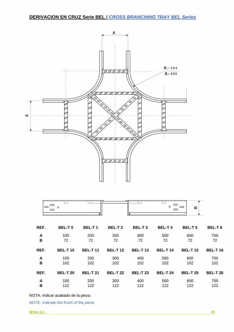
DERIVACION EN CRUZ Serie BEL / CROSS BRANCHING TRAY BEL Series
REF. BEL-T 0 BEL-T 1 BEL-T 2 BEL-T 3 BEL-T 4 BEL-T 5 BEL-T 6
A 100 200 300 400 500 600 700B 72 72 72 72 72 72 72
REF. BEL-T 10 BEL-T 11 BEL-T 12 BEL-T 13 BEL-T 14 BEL-T 15 BEL-T 16
A 100 200 300 400 500 600 700B 102 102 102 102 102 102 102
REF. BEL-T 20 BEL-T 21 BEL-T 22 BEL-T 23 BEL-T 24 BEL-T 25 BEL-T 26
A 100 200 300 400 500 600 700B 122 122 122 122 122 122 122
NOTA: Indicar acabado de la pieza.
NOTE: Indicate the finish of the piece.
IESA,S.L.___________________________________________________________________________ 25

REDUCCION BANDEJA Serie BEL / REDUCING TRAY BEL Series
REDUCCION A DERECHAS / RIGHT REDUCING
REF. BEL-RD 0 BEL-RD 1 BEL-RD 2 BEL-RD 3 BEL-RD 4 BEL-RD 5
A 100 200 300 400 500 600B 200 300 400 500 600 700
REDUCCION A IZQUIERDAS / LEFT REDUCING
REF. BEL-RI 0 BEL-RI 1 BEL-RI 2 BEL-RI 3 BEL-RI 4 BEL-RI 5
A 100 200 300 400 500 600B 200 300 400 500 600 700
REDUCCION CENTRADA / CENTER REDUCING
REF. BEL-RC 0 BEL-RC 1 BEL-RC 2 BEL-RC 3 BEL-RC 4 BEL-RC 5
A 100 200 300 400 500 600B 200 300 400 500 600 700
NOTA: Indicar acabado de la pieza.
NOTE: Indicate the finish of the piece.
IESA,S.L.___________________________________________________________________________ 26

TAPA PARA BANDEJA Serie BEL /COVER TRAY BEL Series
TAPA SENCILLA (TP) TAPA TEJADILLO (TJ)SIMPLE COVER (TP) COVER TOP (TJ)
REF. BEL-TP 0 BEL-TP 1 BEL-TP 2 BEL-TP 3 BEL-TP 4 BEL-TP 5 BEL-TP 6
A 100 200 300 400 500 600 700
REF. BEL-TJ 0 BEL-TJ 1 BEL-TJ 2 BEL-TJ 3 BEL-TJ 4 BEL-TJ 5 BEL-TJ 6
A 100 200 300 400 500 600 700
NOTA: Indicar acabado de la pieza.
NOTE: Indicate the finish of the piece.
IESA,S.L.___________________________________________________________________________ 27

ACCESORIOS BANDEJA Serie BEL / ACCESSORIES TRAY BEL Series
GRAPA DE FIJACION BANDEJAREF. BEG
CLAMP FOR FIXING TRAYREF. BEG
BISAGRAREF. BEL-BSe suministra con 6 tornillos M-10x20con tuercas y arandelas.
HINGEREF. BEL-BSupply with 6 screws M-10x20with nuts and washers.
PLACA DE UNIONREF. BEL-PSe suministra con 6 tornillos M-10x20con tuercas y arandelas.
UNION PLATEREF. BEL-PSupply with 6 screws M-10x20with nuts and washers.
GRAPA FIJACION DE TAPAREF. BEL-GR
CLAMP FOR FIXING COVERREF. BEL-GR
IESA,S.L.___________________________________________________________________________ 28
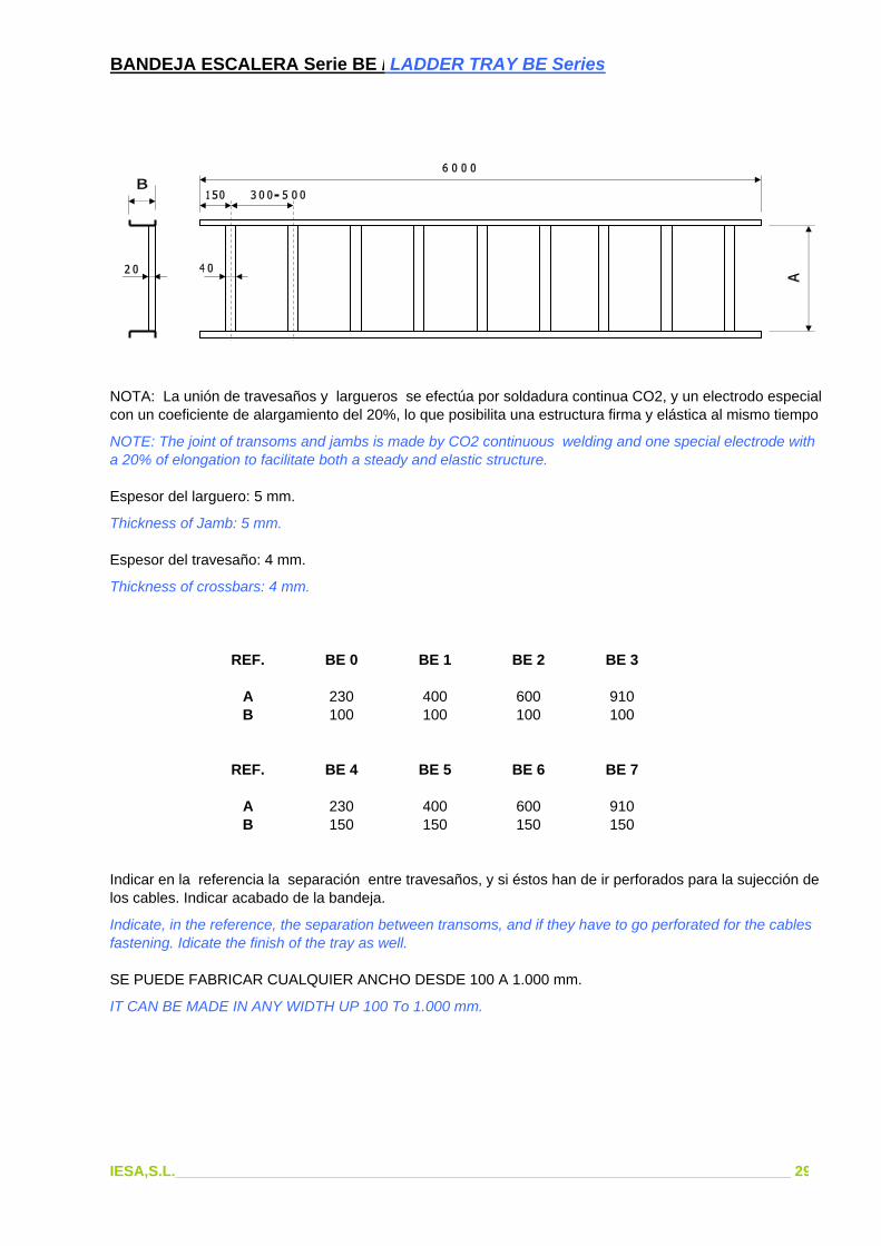
BANDEJA ESCALERA Serie BE / LADDER TRAY BE Series
NOTA: La unión de travesaños y largueros se efectúa por soldadura continua CO2, y un electrodo especialcon un coeficiente de alargamiento del 20%, lo que posibilita una estructura firma y elástica al mismo tiempo
NOTE: The joint of transoms and jambs is made by CO2 continuous welding and one special electrode witha 20% of elongation to facilitate both a steady and elastic structure.
Espesor del larguero: 5 mm.
Thickness of Jamb: 5 mm.
Espesor del travesaño: 4 mm.
Thickness of crossbars: 4 mm.
REF. BE 0 BE 1 BE 2 BE 3
A 230 400 600 910B 100 100 100 100
REF. BE 4 BE 5 BE 6 BE 7
A 230 400 600 910B 150 150 150 150
Indicar en la referencia la separación entre travesaños, y si éstos han de ir perforados para la sujección de los cables. Indicar acabado de la bandeja.
Indicate, in the reference, the separation between transoms, and if they have to go perforated for the cables fastening. Idicate the finish of the tray as well.
SE PUEDE FABRICAR CUALQUIER ANCHO DESDE 100 A 1.000 mm.
IT CAN BE MADE IN ANY WIDTH UP 100 To 1.000 mm.
IESA,S.L.___________________________________________________________________________ 29
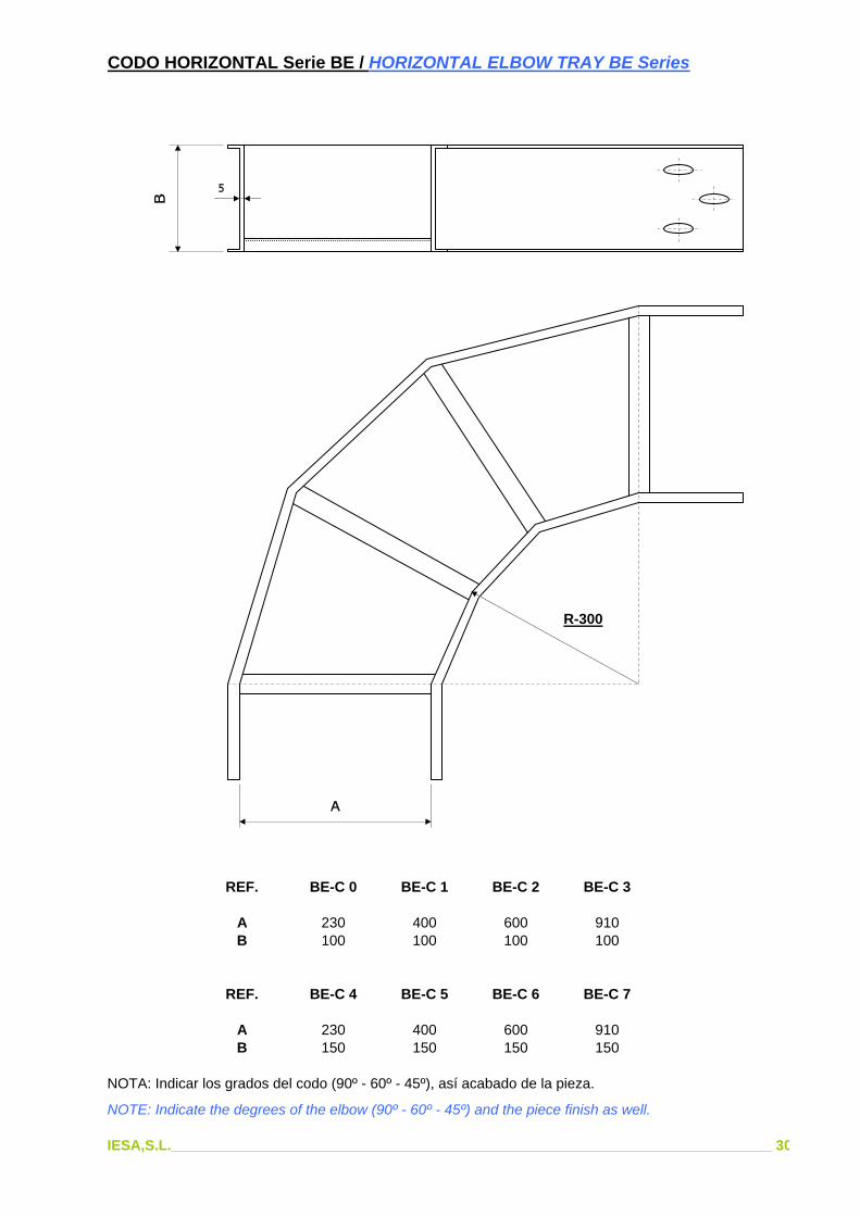
CODO HORIZONTAL Serie BE / HORIZONTAL ELBOW TRAY BE Series
R-300
REF. BE-C 0 BE-C 1 BE-C 2 BE-C 3
A 230 400 600 910B 100 100 100 100
REF. BE-C 4 BE-C 5 BE-C 6 BE-C 7
A 230 400 600 910B 150 150 150 150
NOTA: Indicar los grados del codo (90º - 60º - 45º), así acabado de la pieza.
NOTE: Indicate the degrees of the elbow (90º - 60º - 45º) and the piece finish as well.
IESA,S.L.___________________________________________________________________________ 30

CODO CONCAVO Serie BE / CONCAVE ELBOW TRAY BE Series
R-300
REF. BE-CC 0 BE-CC 1 BE-CC 2 BE-CC 3
A 230 400 600 910B 100 100 100 100
REF. BE-CC 4 BE-CC 5 BE-CC 6 BE-CC 7
A 230 400 600 910B 150 150 150 150
NOTA: Indicar los grados del codo (90º - 60º - 45º), así acabado de la pieza.
NOTE: Indicate the degrees of the elbow (90º - 60º - 45º) and the piece finish as well.
IESA,S.L.___________________________________________________________________________ 31

CODO CONVEXO Serie BE / CONVEX ELBOW TRAY BE Series
R-300
REF. BE-CX 0 BE-CX 1 BE-CX 2 BE-CX 3
A 230 400 600 910B 100 100 100 100
REF. BE-CX 4 BE-CX 5 BE-CX 6 BE-CX 7
A 230 400 600 910B 150 150 150 150
NOTA: Indicar los grados del codo (90º - 60º - 45º), así acabado de la pieza.
NOTE: Indicate the degrees of the elbow (90º - 60º - 45º) and the piece finish as well.
IESA,S.L.___________________________________________________________________________ 32

DERIVACION EN TE Serie BE / TE BRANCHING TRAY BE Series
REF. BE-T 0 BE-T 1 BE-T 2 BE-T 3
A 230 400 600 910B 100 100 100 100
REF. BE-T 4 BE-T 5 BE-T 6 BE-T 7
A 230 400 600 910B 150 150 150 150
NOTA: Indicar acabado de la pieza.
NOTE: Indicate this finish of the piece.
IESA,S.L.___________________________________________________________________________ 33

DERIVACION EN CRUZ Serie BE / CROSS BRANCHING TRAY BE Series
REF. BE-CZ 0 BE-CZ 1 BE-CZ 2 BE-CZ 3
A 230 400 600 910B 100 100 100 100
REF. BE-CZ 4 BE-CZ 5 BE-CZ 6 BE-CZ 7
A 230 400 600 910B 150 150 150 150
NOTA: Indicar acabado de la pieza.
NOTE: Indicate this finish of the piece.
IESA,S.L.___________________________________________________________________________ 34

REDUCCION BANDEJA Serie BE / REDUCING TRAY BE Series
REDUCCION A DERECHAS / RIGHT REDUCING
REF. BE-RD 0 BE-RD 1 BE-RD 2
A 230 400 600B 400 600 910
REDUCCION A IZQUIERDAS / LEFT REDUCING
REF. BE-RI 0 BE-RI 1 BE-RI 2
A 230 400 600B 400 600 910
REDUCCION CENTRADA / CENTER REDUCING
REF. BE-RC 0 BE-RC 1 BE-RC 2
A 230 400 600B 400 600 910
NOTA: Indicar acabado de la pieza.
NOTE: Indicate this finish of the piece.
IESA,S.L.___________________________________________________________________________ 35

TAPA PARA BANDEJA Serie BE /COVER TRAY BE Series
TAPA SENCILLA (TP) TAPA TEJADILLO (TJ)SIMPLE COVER (TP) COVER TOP (TJ)
REF. BE-TP 0 BE-TP 1 BE-TP 2 BE-TP 3
A 230 400 600 910
REF. BE-TJ 0 BE-TJ 1 BE-TJ 2 BE-TJ 3
A 230 400 600 910
NOTA: Indicar acabado de la pieza.
NOTE: Indicate this finish of the piece.
IESA,S.L.___________________________________________________________________________ 36

SEPARADOR PARA BANDEJA Serie BE /SEPARATOR FOR TRAY BE Series
Separador Separator
Bandeja Tray
Es importante definir la distancia entre travesaños de la bandeja sobre la que va montado el separador.El tornillo de fijación es de M-6x15, con tuercas y arandelas.
IT is important to define the distance between transoms of the tray on which the separator will be set.The screw of fixation is of M-6x15, with nuts and washers.
REF. BE-S 0 BE-S 1
A 80 130
GRAPA PARA BANDEJA Serie BE /CLAMP FOR TRAY BE Series
Se suministra sin tornillo.
Supply without screw.
IESA,S.L.___________________________________________________________________________ 37

CANAL CERRADO CON TRAVESAÑOS Serie CT / CLOSED CHANNEL WITH TRANSOMS CT Series
REF. CT 0 CT 1 CT 2 CT 3 CT 4 CT 5
A 100 200 300 400 500 600B 100 100 100 100 100 100
También se fabrican codos horizontales (90º, 60º, 45º), codos verticales (90º, 60º, 45º), Tes y Cruces.NOTA: Indicar espesor y acabado de la pieza.
Also horizontal elbows (90º, 60º, 45º), vertical elbows (90º, 60º, 45º), Tes and Crosses can be.manufactured.NOTE: Indicate thickness and the finish of the piece.
IESA,S.L.___________________________________________________________________________ 38

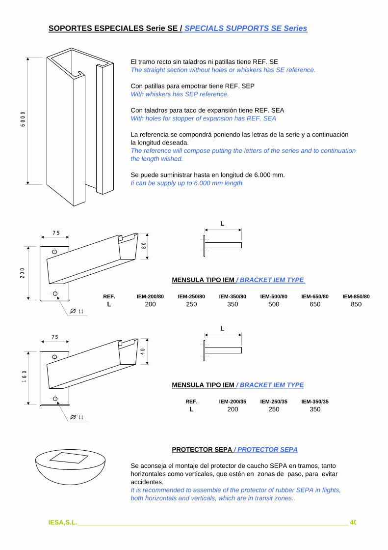
SOPORTES ESPECIALES Serie SE / SPECIALS SUPPORTS SE Series
El soporte estructural de IESA se basa en un concepto de diseño que auna tres funciones determinantes en todo montaje mecánico: facilidad de montaje, robustez y versatilidad. El sistema consiste básicamente en un perfil de chapa (Fig. 1) plegado de tal forma que permite deslizarse por su interior una grapa de acero estampada que se coloca en la placa de la ménsula o travesaño y que al ser puesta en posición de trabajo y apretada, nos asegura una unión firme y segura del elemento sobre el tramo descendente del soporte (Fig. 2). El material es de acero de primera calidad y el acabado galvanizado por inmersión en caliente con una deposición de cinz de 70 micras. Las grapas y tornillería, electrocincada con 20 micras de espesor.
The structural support is bases in one design composed of 3 determinant functions during the mechanical assembly: simplicity, robustness and versatility. Basically, the system consists of one profile of plate (Fig. 1) folded in such a way that it allows one stamped steel clamp to glide internally that is placed in the plate of bracket or tansom. It ensures us a firm and safe union of the element to the
Fig. (1) downward flight of the bear, when it is placed and tightened in its position.(Fig. 2). They are made in first quality steel with hot dip galvanized finish and 70 microns of thickness. The clamp and screws, 20 microns of tchickness.
yDATOS PARA EL CALCULODATA FOR CALCULATION
EJE xx / AXLE xx
Momento de Inercia Ixx = 30,445 cm4Moment of inertia Ixx = 30,445 cm4
Módulo resistente Wxx = 7,574 cm3Resistant turning Wxx = 7,574 cm3
x x Radio de giro ixx = 2,021 cmRadius of twist ixx = 2,021 cm
EJE yy / AXILE yy
Momento de Inercia Iyy = 39,338 cm4Moment of inertia Iyy = 39,338 cm4
Módulo resistente Wyy = 13,113 cm3Resistant turning Wyy = 13,113 cm3
yRadio de giro iyy = 2,297 cm
Fig. (2) Radius of twist iyy = 2,297 cm
IESA,S.L.___________________________________________________________________________ 39
SOPORTES ESPECIALES Serie SE / SPECIALS SUPPORTS SE Series
El tramo recto sin taladros ni patillas tiene REF. SEThe straight section without holes or whiskers has SE reference.
Con patillas para empotrar tiene REF. SEPWith whiskers has SEP reference.
Con taladros para taco de expansión tiene REF. SEAWith holes for stopper of expansion has REF. SEA
La referencia se compondrá poniendo las letras de la serie y a continuaciónla longitud deseada.The reference will compose putting the letters of the series and to continuationthe length wished.
Se puede suministrar hasta en longitud de 6.000 mm.Ii can be supply up to 6.000 mm length.
L
MENSULA TIPO IEM / BRACKET IEM TYPE
REF. IEM-200/80 IEM-250/80 IEM-350/80 IEM-500/80 IEM-650/80 IEM-850/80L 200 250 350 500 650 850
L
MENSULA TIPO IEM / BRACKET IEM TYPE
REF. IEM-200/35 IEM-250/35 IEM-350/35L 200 250 350
PROTECTOR SEPA / PROTECTOR SEPA
Se aconseja el montaje del protector de caucho SEPA en tramos, tantohorizontales como verticales, que estén en zonas de paso, para evitaraccidentes.It is recommended to assemble of the protector of rubber SEPA in flights,both horizontals and verticals, which are in transit zones..
IESA,S.L.___________________________________________________________________________ 40

SOPORTES ESPECIALES Serie SE / SPECIALS SUPPORTS SE Series
TIPO IED / IED TYPE
REF. IED 10 IED 15 IED 20 IED 25 IED 30L 1000 1500 2000 2500 3000
TIPO IES / IES TYPE
REF. IES 10 IES 15 IES 20 IES 25 IES 30L 1000 1500 2000 2500 3000
TIPO SET / SET TYPE
REF. SET 75 SET 10 SET 12L 750 1000 1200
IESA,S.L.___________________________________________________________________________ 41

SOPORTES ESPECIALES Serie SE / SPECIALS SUPPORTS SE Series
TIPO IET / IET TYPE
REF. IET 25 IET 35 IET 50 IET 65 IET 85 IET 100L 250 350 500 650 850 1000
IESA,S.L.___________________________________________________________________________ 42
REFERENCE SEE
CLAMP REFERENCE SEB
CLAMP REFERENCE SEG
CLAMP REFERENCE SEXRetail of tray fixation CLAMP SEG CLAMP SE
SOPORTES ESPECIALES Serie SE / SPECIALS SUPPORTS SE Series
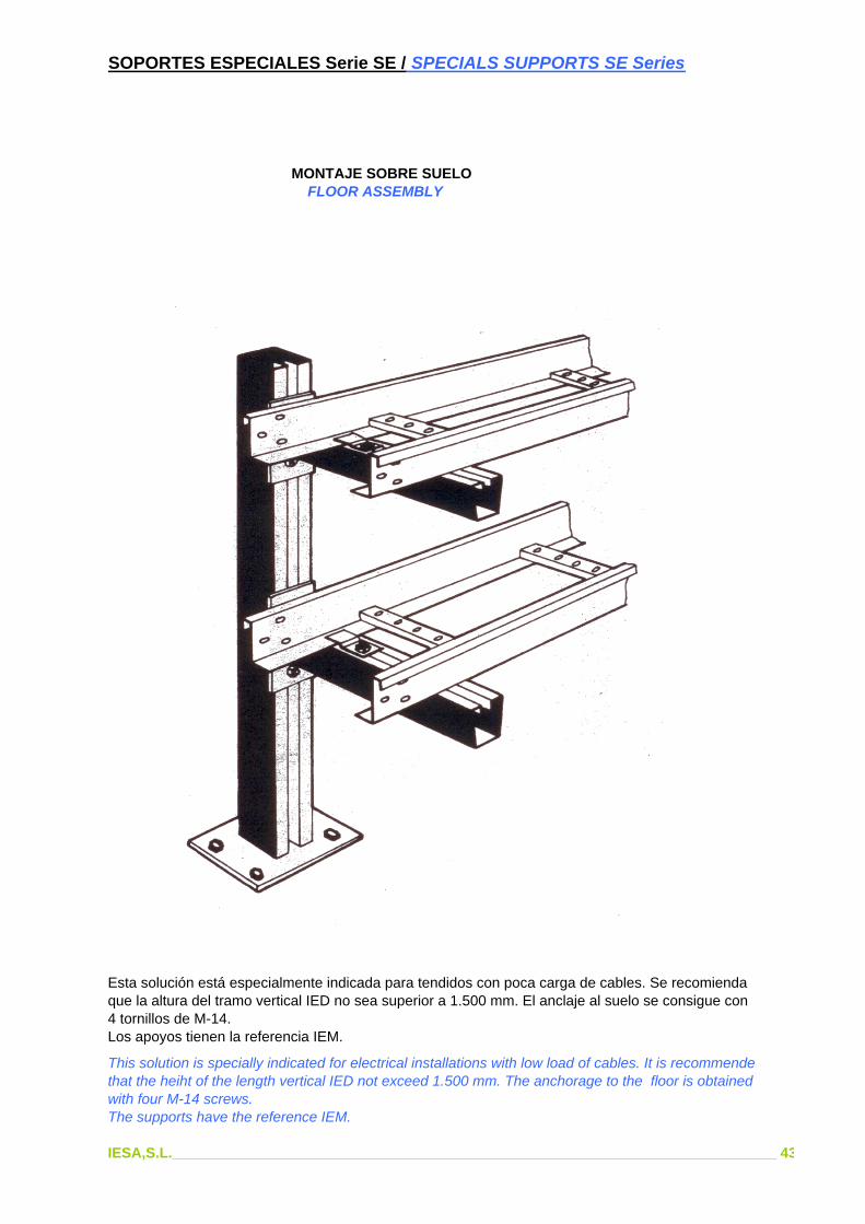
MONTAJE SOBRE SUELO FLOOR ASSEMBLY
Esta solución está especialmente indicada para tendidos con poca carga de cables. Se recomiendaque la altura del tramo vertical IED no sea superior a 1.500 mm. El anclaje al suelo se consigue con4 tornillos de M-14.Los apoyos tienen la referencia IEM.
This solution is specially indicated for electrical installations with low load of cables. It is recommende that the heiht of the length vertical IED not exceed 1.500 mm. The anchorage to the floor is obtained with four M-14 screws.The supports have the reference IEM.
IESA,S.L.___________________________________________________________________________ 43

SOPORTES ESPECIALES Serie SE / SPECIALS SUPPORTS SE Series
MONTAJE SOBRE SUELO FLOOR ASSEMBLY
Este tipo de montaje permite el tendido de cables con mucha carga, hasta alturas de 3.000 mm. Eltramo vertical tiene la referencia IED y el travesaño se denomina IET.También se pueden montar las bandejas sobre escuadras SEE.
This type of assembly allows heavy load electrical installation up to 3.000 mm heights. The lengthvertical has the reference IED and the transoms is named.The trays also can be assembles on SEE squares.
IESA,S.L.___________________________________________________________________________ 44

SOPORTES ESPECIALES Serie SE / SPECIALS SUPPORTS SE Series
MONTAJE SOBRE TECHO ROOF ASSEMBLY
Este sistema de montaje posibilita el montaje de bandejas en instalaciones en las cuales el techosea de hormigón.Puede hacerse según se indica en el dibujo, o bien anclando los tramos descendentes tipo IED(sencillo) ó IES (doble) directamente al techo.Cuando se trate de cargas descentradas se recomienda usar los tirantes a ambos lados SET, asícomo en el caso de que el tramo descendente sea superior a 3.000 mm. y la bandeja superior a 300mm. de ancho.Para una perfecta alineación se recomienda el montaje tal como aparece en le dibujo.
This system facilitates the assembly of trays in installations with concrete roof.It can do it as in draw above, or anchoring the downward lengths IED type (simple) or IES (double),directly to the roof.When it should refer to off-centre loads, it is recommended to use the braces on both SET sides,also if the downward length is bigger than 3.000 mm and the tray exceeds 300 mm of wide.It is recommended to do the assembly as draw above for a perfect alignment.
IESA,S.L.___________________________________________________________________________ 45

SOPORTES ESPECIALES Serie SE / SPECIALS SUPPORTS SE Series
SOPORTES ANCLADOS A MUROSUPPORTS ANCHORED TO WALL
CON PATILLAS PARA EMPOTRAR CON TACOS PARA FIJAR WITH SUBJECTIONS BUILD IN A TACO DE EXPASION
WITH PLUGS TO FIXTO PLUG OF EXPASION
Las patillas para empotrar, así como las perforaciones para tacos de expansión, van emplazadas cada 500 mm.El perfil en ambos casos soporta cargas hasta 1.400 Kg/m.
These products as well as the boxes of expansion plugs are located each 500 mm. The profile, in both cases, bears up to 1.400 Kg/m.
IESA,S.L.___________________________________________________________________________ 46

SOPORTES Serie S / SUPPORTS S Series
Ref. S 0 S 1 S 2 S 3 S 4 S 5 S 6 A 150 250 350 450 550 650 750
Ref. S 60 S 61 S 62 S 63 S 64 A 140 200 325 525 725 B 90 150 275 475 675
IESA,S.L.___________________________________________________________________________ 47
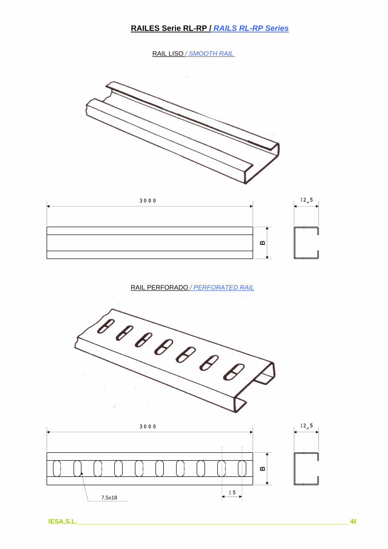
RAILES Serie RL-RP / RAILS RL-RP Series
RAIL LISO / SMOOTH RAIL
RAIL PERFORADO / PERFORATED RAIL
7,5x18
IESA,S.L.___________________________________________________________________________ 48

GRAPAS PORTACABLES SOBRE RAIL Serie GP / CLAMPS GP Series
11x20
MATERIAL : CHAPA DE ACERO DE 2 mm DE ESPESOR GALVANIZADA
MATERIAL : STEEL PLATE OF 2 mm OF THICKNESS GALVANIZED
L = 500 - 800 - 100
Fichas
MATERIAL NYLON (Color Negro)
MATERIAL NYLON (Black)
REF. Cable mm
C03 14-48
C03 24-72
IESA,S.L.___________________________________________________________________________ 49