indian scenario of super critical power plants issues and ... · sipat & barh –supercritical...
TRANSCRIPT

Indian Scenario of Super Critical
Power Plants
Issues and Challenges
T K Seal - GM(COS-OPN)
D.Bose -AGM(COS-Commng)

Supercritical Units –Indian scenario
1. Power scenario in India
2. What is Supercritical Technology
3. Benefits of Supercritical Technology
4. Supercritical Units in India
5. Profile of NTPC
6. Sipat & Barh –Supercritical Units of NTPC
7. Chemistry Regime
8. Boiler Control- Sliding Pressure Operation
9. Issues & Challenges
10. Sipat - Performance at a Glance
11. Q & A
Contents
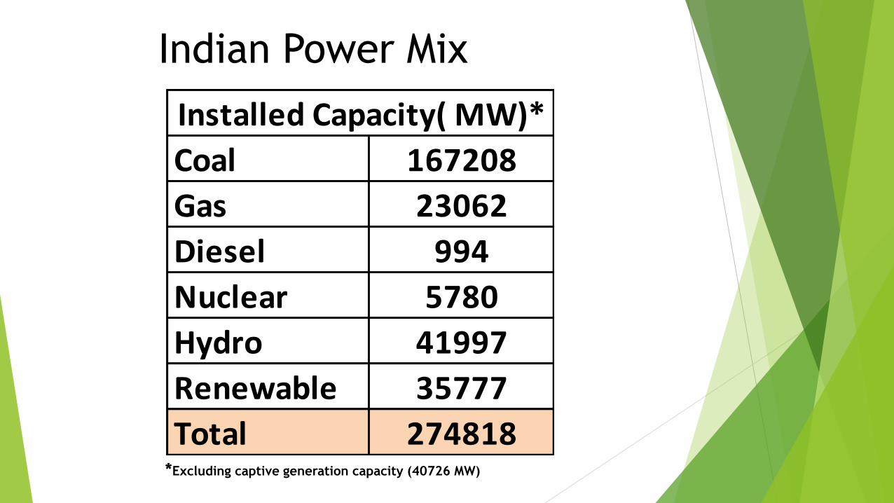
Coal 167208
Gas 23062
Diesel 994
Nuclear 5780
Hydro 41997
Renewable 35777
Total 274818
Installed Capacity( MW)*
Indian Power Mix
*Excluding captive generation capacity (40726 MW)
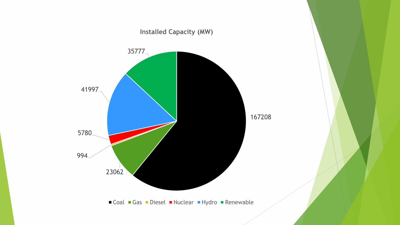
167208
23062
994
5780
41997
35777
Installed Capacity (MW)
Coal Gas Diesel Nuclear Hydro Renewable

Share of supercritical units (MW)
11.35%
88.65%
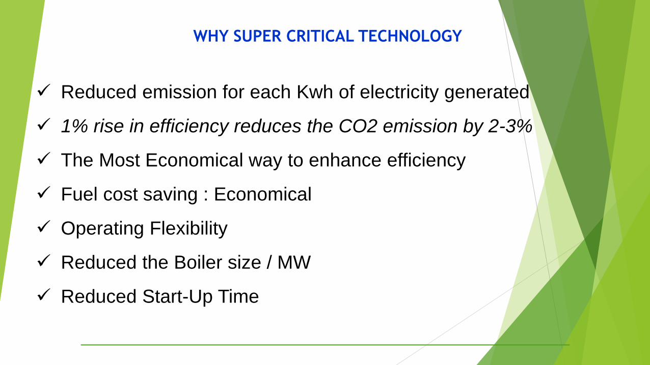
Reduced emission for each Kwh of electricity generated
1% rise in efficiency reduces the CO2 emission by 2-3%
The Most Economical way to enhance efficiency
Fuel cost saving : Economical
Operating Flexibility
Reduced the Boiler size / MW
Reduced Start-Up Time
WHY SUPER CRITICAL TECHNOLOGY
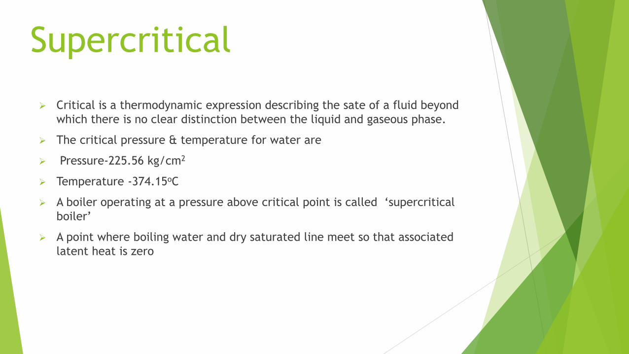
Critical is a thermodynamic expression describing the sate of a fluid beyond
which there is no clear distinction between the liquid and gaseous phase.
The critical pressure & temperature for water are
Pressure-225.56 kg/cm2
Temperature -374.15oC
A boiler operating at a pressure above critical point is called ‘supercritical
boiler’
A point where boiling water and dry saturated line meet so that associated
latent heat is zero
Supercritical

SUPER CRITICAL
BOILER CYCLE WITH SH, RH & Regeneration
Steam temp : 540 Deg.C
Steam Pres : 256 kg/cm2
RH pre : 51.6 kg/cm2
RH Temp : 568 Deg.C
Feed water Temp : 291 Deg.C
0
100
200
300
400
500
600 540oC 568oC
ENTROPY
TEMP 1
2
3
45

Boiling process in Tubular Geometries

Sub Critical – Ultra Super Critical
March Towards Higher Efficiency With
Application of Higher Grades of Materials
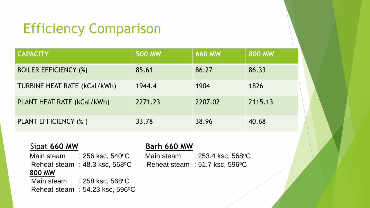
Efficiency Comparison
CAPACITY 500 MW 660 MW 800 MW
BOILER EFFICIENCY (%) 85.61 86.27 86.33
TURBINE HEAT RATE (kCal/kWh) 1944.4 1904 1826
PLANT HEAT RATE (kCal/kWh) 2271.23 2207.02 2115.13
PLANT EFFICIENCY (% ) 33.78 38.96 40.68
Sipat 660 MW
Main steam : 256 ksc, 540oC
Reheat steam : 48.3 ksc, 568oC
800 MW
Main steam : 258 ksc, 568oC
Reheat steam : 54.23 ksc, 596oC
Barh 660 MW
Main steam : 253.4 ksc, 568oC
Reheat steam : 51.7 ksc, 596oC

INCREASE IN PLANT EFFICIENCY by SUPER
CRITICAL PARAMETERS
1.5
0.90.6
3.2
167 bar
538/538oC250 bar
538/538oC250 bar
540/560oC
250 bar
580/600oC
250bar
566/566oC
1
2
3
4
5
6
.
Efficiency Increase

Existing supercritical units State Station Capacity
Bihar Barh (NTPC) #4 660
Barh (NTPC) #5 660
Chattisgarh Sipat (NTPC) #1 660
Sipat (NTPC) #2 660Sipat (NTPC) #3 660
Maharashtra Koradi #8 660
Tirora TPP(Phase 1) #1 660
Tirora TPP(Phase 1) #2 660Tirora TPP(Phase2) #1 660
Tirora TPP(Phase2) #2 660
Tirora TPP(Phase2) # 3 660
Andhra Pradesh Painampuram TPP #1 660
Gujrat Mundra UMPP #3 800Mundra UMPP#4 800
Mundra UMPP#5 800
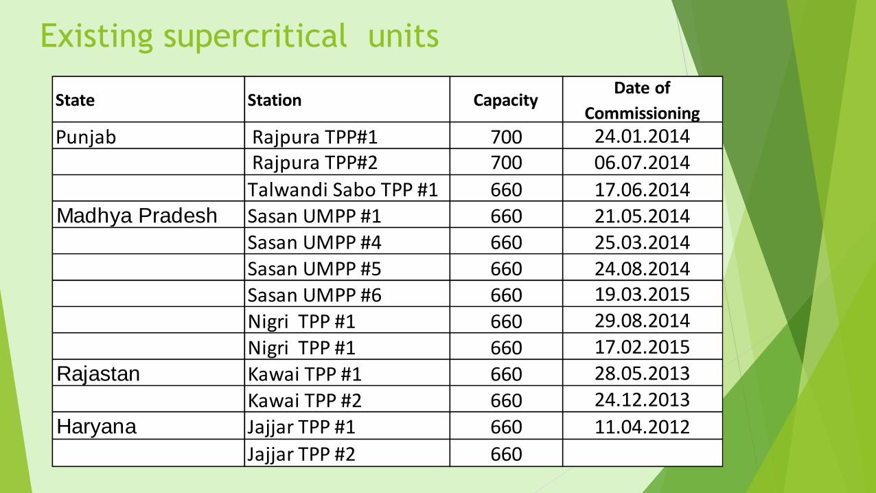
Existing supercritical units
State Station Capacity Date of
Commissioning
Punjab Rajpura TPP#1 700 24.01.2014 Rajpura TPP#2 700 06.07.2014
Talwandi Sabo TPP #1 660 17.06.2014Madhya Pradesh Sasan UMPP #1 660 21.05.2014
Sasan UMPP #4 660 25.03.2014Sasan UMPP #5 660 24.08.2014Sasan UMPP #6 660 19.03.2015
Nigri TPP #1 660 29.08.2014
Nigri TPP #1 660 17.02.2015
Rajastan Kawai TPP #1 660 28.05.2013
Kawai TPP #2 660 24.12.2013
Haryana Jajjar TPP #1 660 11.04.2012
Jajjar TPP #2 660
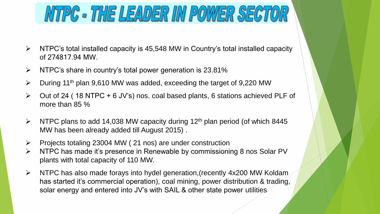
NTPC’s total installed capacity is 45,548 MW in Country’s total installed capacity
of 274817.94 MW.
NTPC’s share in country’s total power generation is 23.81%
During 11th plan 9,610 MW was added, exceeding the target of 9,220 MW
Out of 24 ( 18 NTPC + 6 JV’s) nos. coal based plants, 6 stations achieved PLF of
more than 85 %
NTPC plans to add 14,038 MW capacity during 12th plan period (of which 8445
MW has been already added till August 2015) .
Projects totaling 23004 MW ( 21 nos) are under construction
NTPC has made it’s presence in Renewable by commissioning 8 nos Solar PV
plants with total capacity of 110 MW.
NTPC has also made forays into hydel generation,(recently 4x200 MW Koldam
has started it’s commercial operation), coal mining, power distribution & trading,
solar energy and entered into JV’s with SAIL & other state power utilities
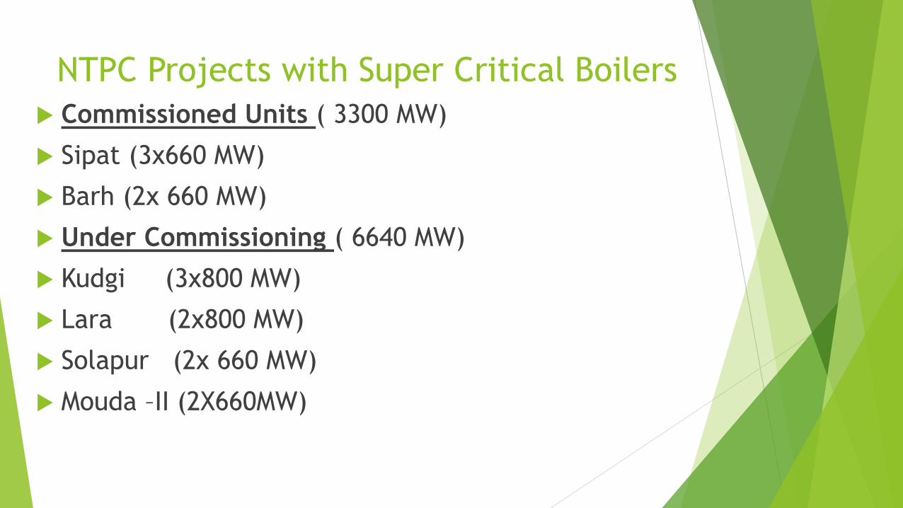
NTPC Projects with Super Critical Boilers
Commissioned Units ( 3300 MW)
Sipat (3x660 MW)
Barh (2x 660 MW)
Under Commissioning ( 6640 MW)
Kudgi (3x800 MW)
Lara (2x800 MW)
Solapur (2x 660 MW)
Mouda –II (2X660MW)
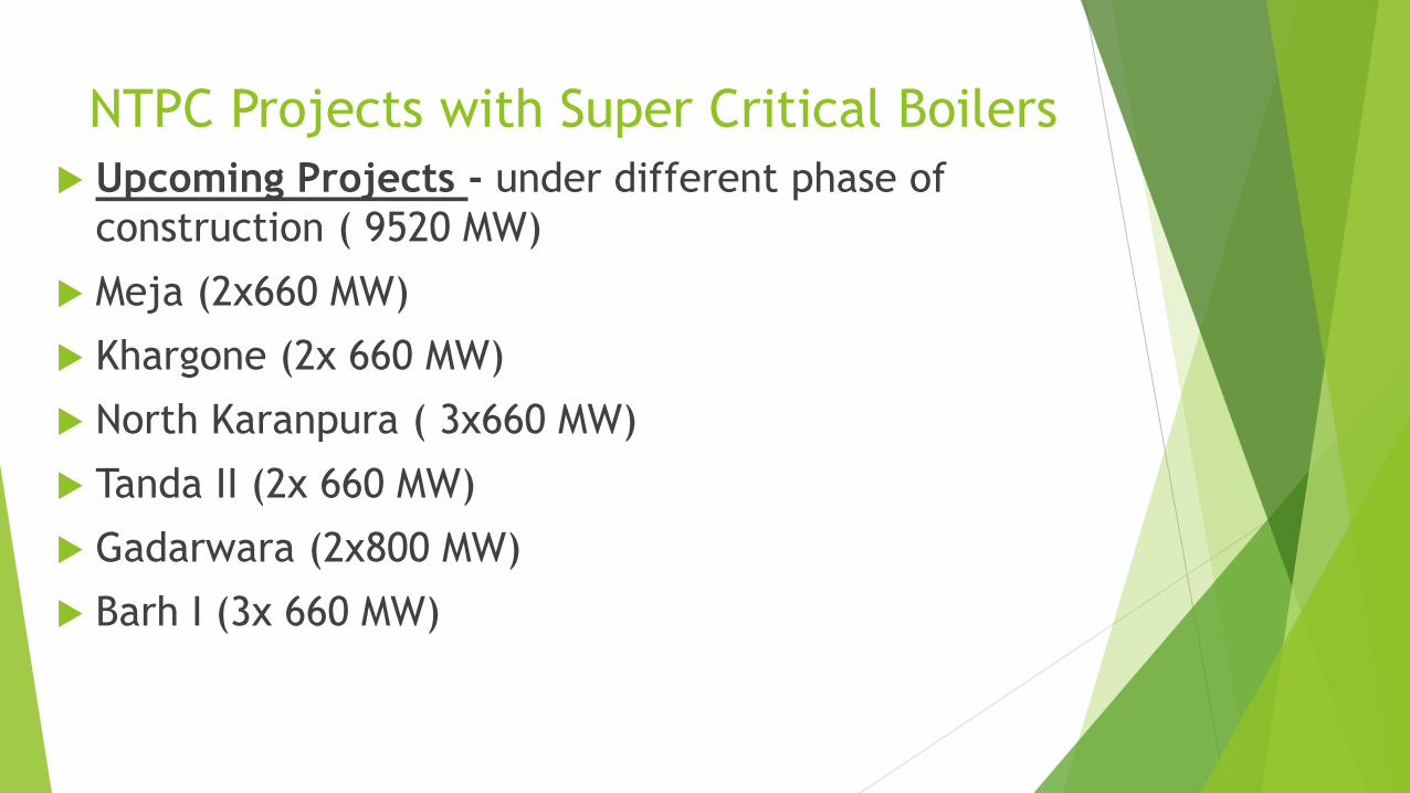
NTPC Projects with Super Critical Boilers
Upcoming Projects - under different phase of
construction ( 9520 MW)
Meja (2x660 MW)
Khargone (2x 660 MW)
North Karanpura ( 3x660 MW)
Tanda II (2x 660 MW)
Gadarwara (2x800 MW)
Barh I (3x 660 MW)
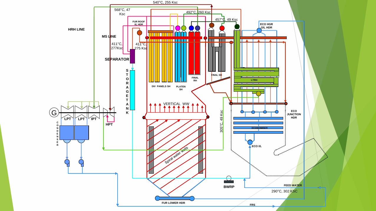
HPT
IPTLPTC
O
N
D
E
N
S
E
R
FEED WATER
FRS
S
T
O
R
A
G
E
T
A
N
K
SEPARATOR
BWRP
MS LINE
HRH LINE
VERTICAL WW
ECO I/L
ECO
JUNCTION
HDR
ECO HGR
O/L HDR
FUR LOWER HDR
FUR ROOF
I/L HDR
DIV PANELS SH PLATEN
SH
FINAL
RH
FINAL SH
LTRH
ECONOMISER
290°C, 302 KSC
411°C,
277Ksc411°C,
275 Ksc
492°C, 260 Ksc
540°C, 255 Ksc
30
5°C
, 4
9 K
sc
457°C, 49 Ksc
568°C, 47
Ksc
GLPT
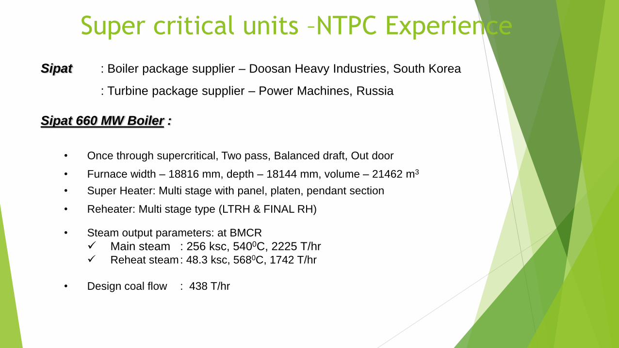
Sipat : Boiler package supplier – Doosan Heavy Industries, South Korea
: Turbine package supplier – Power Machines, Russia
Sipat 660 MW Boiler :
• Once through supercritical, Two pass, Balanced draft, Out door
• Furnace width – 18816 mm, depth – 18144 mm, volume – 21462 m3
• Super Heater: Multi stage with panel, platen, pendant section
• Reheater: Multi stage type (LTRH & FINAL RH)
• Steam output parameters: at BMCR
Main steam : 256 ksc, 5400C, 2225 T/hr Reheat steam: 48.3 ksc, 5680C, 1742 T/hr
• Design coal flow : 438 T/hr
Super critical units –NTPC Experience

1. Fans
ID Fan : Supplier : FlaktWoods, Sweeden
Type : PFSU – 450 – 300 – 08
FD Fan : Supplier : FlaktWoods, Sweeden
Type : PFSU – 280 – 112 – 04
PA Fan : Supplier : FlaktWoods, SweedenType : PFTU – 200 – 100 – 02
2. Air Preheaters
SAPH : Supplier : DoosanType : 31.5 – VI – 1900
PAPH : Supplier : DoosanType : 26.0 – VI – 1800
3. Mills
Vertical Bowl Mill 10 nos. – XHPS 1103
4. Coal Feeder
Gravimetric feeder 10 nos. – 36 inch
5. Boiler Recirculation Pump (BRP)
Make : Hayward Taylor, England
Type : Wet stator, Glandless, Single section sing discharge
pump
6. Oil elevations : 5 nos. (AB, CD, EF, GH & JK)
BOILER AUXILIARIES :Super critical units –NTPC Experience

Sipat 660 MW Turbine :
• Turbine Model: K-660-247 (LMZ, Russia)
• HP Turbine
1 no. HP turbine, 17 stages
HP turbine has nozzle governing system
2 nos. HP stop valves, 4 nos. HP control valves
1 impulse stage + 16 reaction stages
• IP Turbine
1 no. IP turbine, 11X2 stages
IP turbine has throttle governing system
2 nos. IP stop valves, 4nos. IP control valves
22 nos. impulse stages
• LP Turbine
2 nos. LP turbines, (5X2 + 5X2) stages
20 nos. impulse stages
• Number of journal bearing for turbine – 8, Number of journal
bearings for generator – 4.
• 2 nos. MDBFP (30% each) & 2 nos. TDBFP (50% each)
• Steam turbine parameters
Before HPSV : 247 ksc, 5370C, 2023 T/hr
Before IPSV : 43 ksc, 5650C, 1681 T/hr
• Number of HP heaters : 6
• Number of LP heater : 4
Super critical units –NTPC Experience
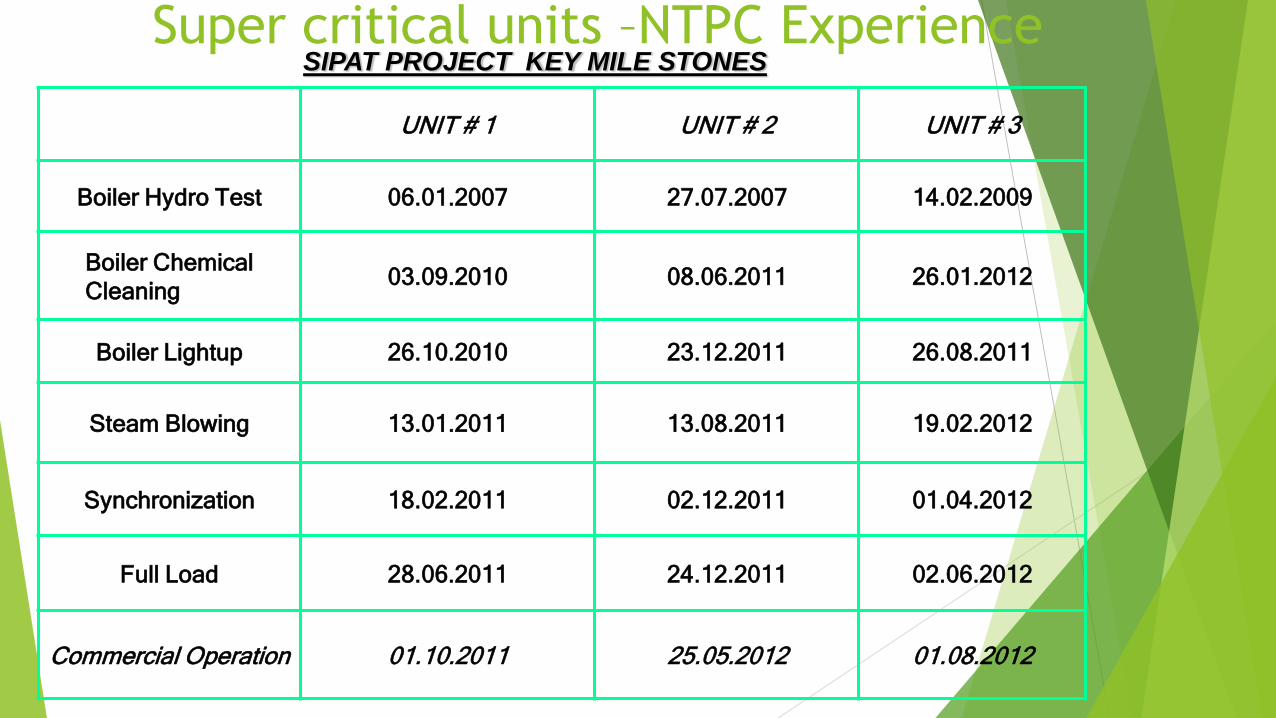
SIPAT PROJECT KEY MILE STONES
UNIT # 1 UNIT # 2 UNIT # 3
Boiler Hydro Test 06.01.2007 27.07.2007 14.02.2009
Boiler Chemical
Cleaning03.09.2010 08.06.2011 26.01.2012
Boiler Lightup 26.10.2010 23.12.2011 26.08.2011
Steam Blowing 13.01.2011 13.08.2011 19.02.2012
Synchronization 18.02.2011 02.12.2011 01.04.2012
Full Load 28.06.2011 24.12.2011 02.06.2012
Commercial Operation 01.10.2011 25.05.2012 01.08.2012
Super critical units –NTPC Experience

Super critical units –NTPC Experience
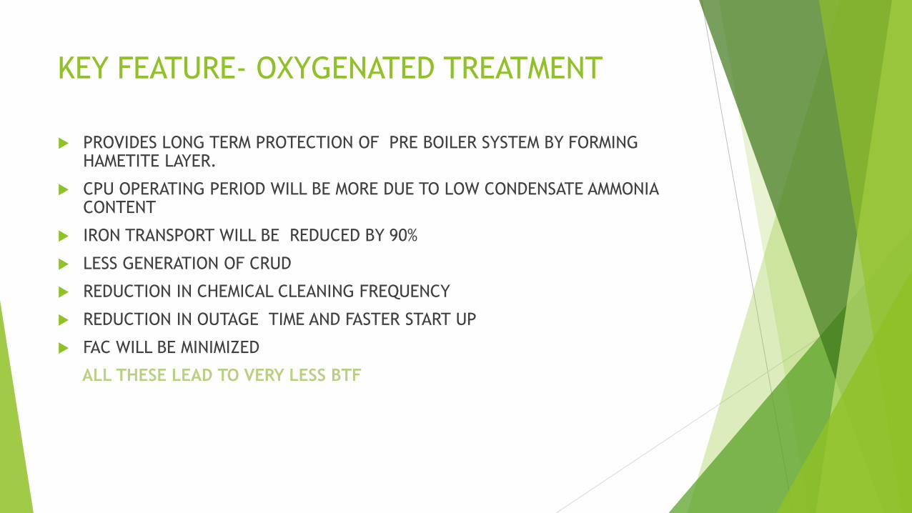
KEY FEATURE- OXYGENATED TREATMENT
PROVIDES LONG TERM PROTECTION OF PRE BOILER SYSTEM BY FORMING HAMETITE LAYER.
CPU OPERATING PERIOD WILL BE MORE DUE TO LOW CONDENSATE AMMONIA CONTENT
IRON TRANSPORT WILL BE REDUCED BY 90%
LESS GENERATION OF CRUD
REDUCTION IN CHEMICAL CLEANING FREQUENCY
REDUCTION IN OUTAGE TIME AND FASTER START UP
FAC WILL BE MINIMIZED
ALL THESE LEAD TO VERY LESS BTF
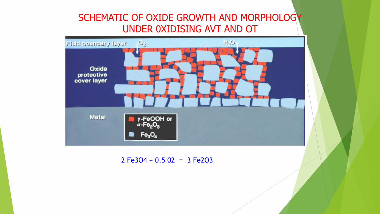
SCHEMATIC OF OXIDE GROWTH AND MORPHOLOGY UNDER 0XIDISING AVT AND OT
2 Fe3O4 + 0.5 02 = 3 Fe2O3

FEED WATER PARAMETERS
S.NO Parameter Units Normal Operation During
Start up
Alkaline water
Treatment
Oxygenated
Treatment
1 PH Min 9.0 8-8.5 Min 9.0
2 Cation Conductivity,
ms/cm
ms/cm Max 0.2 <0.15 Max 0.5
3 Dissolved Oxygen ppb < 5 30-150 Max 100
4 Iron ppb < 2 < 2 < 20
5 Sodium ppb < 2 < 2 < 10
6 Silica ppb <10 < 10 < 30
7 Turbidity NTU <2 < 2 <5

OXYGENATED TREATMENT SYSTEM AT
SIPAT – OXYGEN DOSING
Dosing is being carried out in CPU outlet and
Deaerator outlet
The cycle oxygen is controlled by flow control
valve having a automatic controller.
The injection control is automatically adjusted
by Feed water flow and residual dissolved
oxygen and set point.
DO should be in the range of < 20 ppb in
condensate.

STEAM WATER ANALYSIS SYSTEM (SWAS)
FOLLOWING IS THE PROCESS MONITORING FOR CHEMICAL CONTROL OF
STEAM AND WATER
S.NO SYSTEM TYPE OF MEASUREMENT
1 MAKE UP DM WATER SP.COND., CATION CONDUCTIVITY
(ACC)
2 CEP DISCHARGE pH, ACC, Na, DO, SP.COND.,
3 CONDENSATE POLISHER O/L pH, ACC, Na, SILICA, SP.COND.,
4 DEAERATOR OUTLET DO
5 FEED WATER AT
ECONOMIZER INLET
pH, ACC, COND.,HYDRAZINE,SILICA,
TURBIDITY
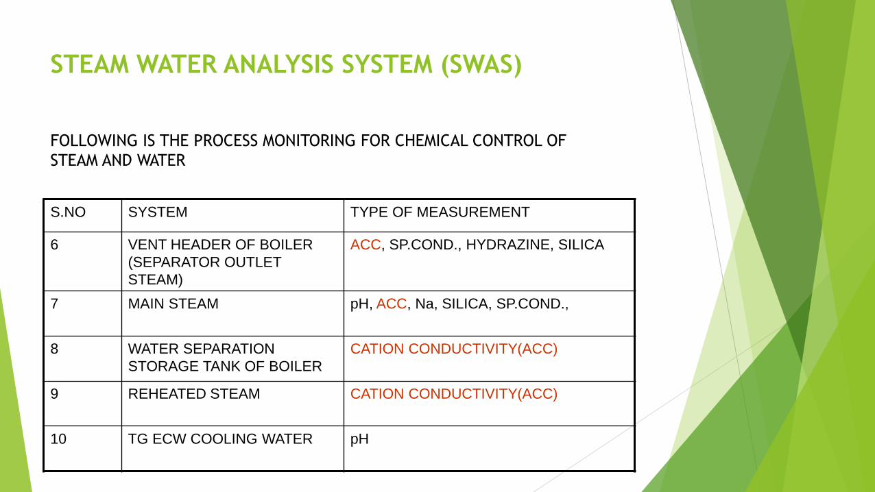
STEAM WATER ANALYSIS SYSTEM (SWAS)
FOLLOWING IS THE PROCESS MONITORING FOR CHEMICAL CONTROL OF
STEAM AND WATER
S.NO SYSTEM TYPE OF MEASUREMENT
6 VENT HEADER OF BOILER
(SEPARATOR OUTLET
STEAM)
ACC, SP.COND., HYDRAZINE, SILICA
7 MAIN STEAM pH, ACC, Na, SILICA, SP.COND.,
8 WATER SEPARATION
STORAGE TANK OF BOILER
CATION CONDUCTIVITY(ACC)
9 REHEATED STEAM CATION CONDUCTIVITY(ACC)
10 TG ECW COOLING WATER pH


Constant Pressure Control
Above 90% TMCR The MS Pressure remains constant at rated pressure
The Load is controlled by throttling the steam flow
Below 30% TMCR the MS Pressure remains constant at minimum
Pressure
Sliding Pressure Control
Boiler Operate at Sliding pressure between 30% and 90% TMCR
The Steam Pressure And Flow rate is controlled by the load directly
BOILER LOAD CONDITION
Sliding pressure operation
Variable pressure operation (sliding pressure operation) isdesired in all modern power plants because it provides moreefficient part load operation.
The loss due to constant pressure operation at low load is alwaysa concern for the utility.
The vertical tube supercritical boiler can provide variableturbine pressure operation to gain the thermodynamicadvantage of variable pressure.
Thus the turbine efficiency advantages are obtained by thesavings in boiler feed pump power associated with true variablepressure operation.
1. No additional pressure loss between boiler and turbine
2. Low Boiler Pr. at low loads
- Less fatigue of Pr. part components
- Longer life of all components, Less wear of components
- Less Maintenance
3. Lower thermal stresses in the turbine during load changes
4. Overall reduction in power consumption and improved heat rate
ADVANTAGES OF SLIDING PRESSURE OPERATION

0
5
10
15
20
25
0 25 50 75 100
Turbine load (%)
Tu
rbin
e in
let
pre
ss
ure
Mp
a
Sliding Pressure

Issues and Challenges
Erection
Commissioning
Operation
Maintenance Practices

Replacement of Grade 23 Pipes and
Fittings
Issue of absence of appropriate microstructure following normalizing heat treatment in thick walled Grade 23 pipes and fittings .
In order to avoid inconvenience during operation in future, It was recommended to replace all Grade 23 pipes and fittings with Grade 91 material
Headers replaced- SH Division panel outlet ( 2nos), Platen SH outlet, Final SH inlet and their connecting pipes.

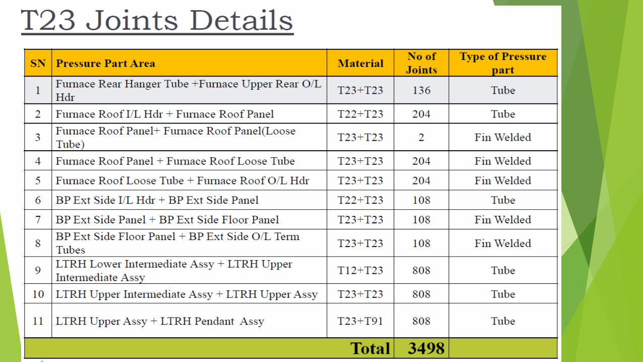
Issues related to Welding Joints of T 23 Tubes
Super critical units –NTPC Experience