indian beacon paper - mx marine indian beacon dgps broadcasting stations network satish mittal, mx...
TRANSCRIPT
1
Indian Beacon DGPS Broadcasting Stations Network
Satish Mittal, MX Marine Leica Geosystems Inc., Torrance
Ajay Seth, Elcome Technology Inc., New Delhi
P.P.Sinha, DGLL, India
BIOGRAPHIES Satish Mittal is the General Manager of MX Marine, Leica Geosystems Inc., Torrance, USA. Satish is also Program Manager for all Differential GPS Systems including DGPS Beacon Systems at MX Marine, Leica. Satish received his BEE degree in 1974 and MEE in 1976 both from Banaras Hindu University in India. Satish received an additional MEE in 1986 from the University of Toronto in Canada. He has more than 26 years experience in various disciplines of marine electronics including the development of sophisticated, large scale integrated navigation systems and DGPS systems. Before immigrating to USA, Satish was working in Department of Electronics, New Delhi where he was responsible for the development of projects for Indian Navy. Ajay Seth is Managing Director of Elcome technology Private limited, India. He holds BEE degree from BHU and MEE degree from University of Southern California. He also has MBA from Pepperdine University in Los Angeles. Ajay has worked for Magnavox/Leica for over 22 years in various positions starting from Project Engineer to the Marine business director in Torrance California. It was under his leadership the Marine beacon system was developed in Magnavox now Leica. He came to India in 1997 to open Leica Geosystems India and was the managing director for Leica Geosystems for six years before joining Elcome Technology. Mr. Seth has been involved in various GPS and DGPS projects in India. P.P. Sinha is Deputy Director in the Directorate General of Lighthouses & Lightships, Ministry of Shipping, Government of India. Sinha passed graduate membership examination of Institution of Electronics and Telecommunication Engineers, India in 1980 with specialization in Radar Engineering, Radio Communication System and Radio Aids to Navigation. Prior to joining the Directorate General of Lighthouses & Lightships, he has worked with the IAF and was associated with maintenance and operations of Radio Aids to Navigation at various Air Traffic Controls. Presently he is associated with planning of Marine Aids to Navigation in the Directorate General of Lighthouses & Lightships. ABSTRACT Marine Beacons were used for direction finding equipment till early 1990. MX Marine, Marine group of Leica developed the first Beacon Modulator and Beacon Demodulator for transmitting the DGPS corrections via Maritime Beacons. The first two systems were installed in Sweden and Finland. In 1993, Director General of Lighthouses and Lightships (DGLL) requested Marine group to prepare a preliminary report for introducing DGPS in India using the Radio beacons used for direction finding application. Based on practical experience and careful evaluation of future needs, DGLL prepared a specification for an advanced DGPS network. The specified network would meet all international
2
standards, be simple to install, easy to operate, both remotely and locally, and would provide excellent accuracy and operational availability, even under adverse conditions. A tender was issued for the initial requirement of ten Broadcast Stations and a contract was awarded to Elcome Marine (Leica dealer for Marine products in India). The contract included the procurement, installation and training on Leica New Generation Beacon DGPS Systems. These systems were commissioned in 1998 (See Table 3). After carefully evaluation of DGPS systems coverage and performance of these ten systems, DGLL issued a second tender for Phase II of Beacon DGPS System Network. A contract was awarded for seven Beacon DGPS systems at the existing Beacon sites and two DGPS systems at new sites with an option for three additional systems. These systems were commissioned and are in operation now. DGLL has awarded the option of three more systems and these systems will be installed soon. After the commissioning of these three stations, Indian Beacon DGPS Network will have 22 Stations in India. Windows NT is used for system software, which takes full advantage of its multi-tasking capabilities. A Windows user interface makes operation of this powerful system simple, intuitive, and easy to absorb. The reference receivers and integrity monitors meet the latest RSIM and RTCM message standards, are extremely rugged, and are designed for continuous unattended operation. Overall, the design provides a complete, turnkey solution, with continuous integrity monitoring, virtually no downtime, and which is easily installed, maintained, and operated. This new generation DGPS System and its capabilities are described, and the excellent field performance of the Indian DGPS Network is documented. The paper also proposes the further expansion of Beacon DGPS network with the Central Monitoring Station. All the base stations and Central station can be connected via Wide Area Network (WAN). The WAN network and current beacon station locations can be used for adding the Automatic Identification System (AIS) Monitoring Stations. In addition to this it is highly recommended that the current Beacon System be upgraded to Dual Frequency GPS Configuration so that it can be part of National Network of GPS for earth quake hazardous assessment in India. INTRODUCTION The original purpose of marine radiobeacons was to provide signals for use by radio direction finders for coastal navigation. The frequencies allocated are in the range of 283.5 - 325.0 KHz. Depending on radiated power and environmental conditions, the beacon signals have a range from 10 - 200 NM. Beacon systems have a number of advantages for broadcast of DGPS corrections. They are in place and maintained, have broad existing coverage, have the necessary frequency allocation, are relatively inexpensive to purchase and operate, and have sufficient power to provide an adequate range for coastal navigation. The modifications to the beacons to enable broadcast of DGPS corrections are straightforward, and do not cause any interference with direction finding. Also, the radiobeacon equipment is reliable, and receivers for the Medium Frequency (MF) beacon signals are not inherently complex. All of these reasons have made beacons the logical candidate for worldwide coastal DGPS. The first detailed considerations of DGPS were started by the United States Coast Guard (USCG) Office of Research and Development (R&D) together with the U.S. Department of Transport (DOT) Transportation Systems Center (TSC) in 1983. In 1986 the RTCM Special Committee 104 made the first recommendations for a general DGPS data format and suggested
3
the use of the existing radio marine beacons for a marine DGPS service. The International Association of Marine Aids to Navigation & Lighthouse Authorities (IALA) Radio Navigation Committee started to look into the prospects of a radiobeacon based DGPS system in 1984. In early 1990, Magnavox Marine group, which is now part of Leica, was awarded a contract for the development of DGPS beacon systems to provide coverage for the Baltic Sea area. Since then, Leica has supplied more than 70 Beacon DGPS systems all over the world. Leica created several new products as part of the beacon system development program. Leica’s GPS navigators were some of the first to be enhanced with beacon system capabilities, allowing seamless integration with the DGPS beacon system. In 1996, Leica developed a New Generation of DGPS Broadcasting Stations [1] Network for Australian Maritime Safety Authority (AMSA). Leica developed the AMSA DGPS Beacon System Network based on AMSA’s specifications and 25 years of experience in the development, engineering, and application of GPS.
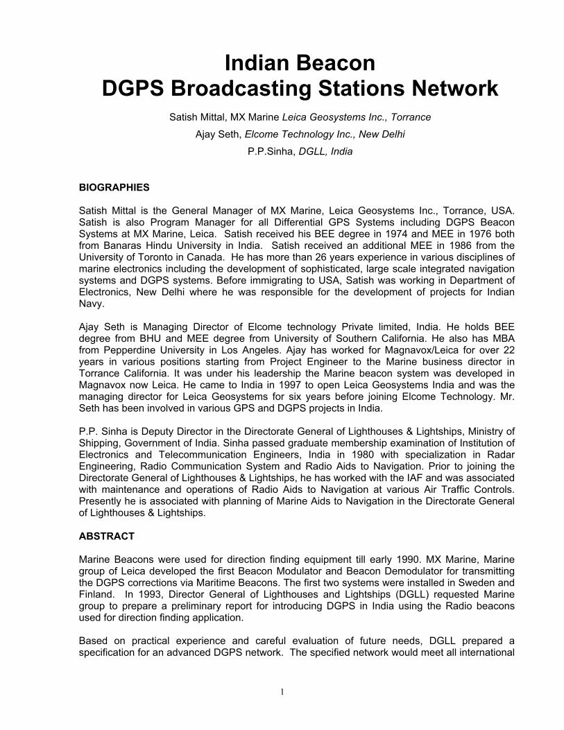
Figure 1: Beacon DGPS Systems (Phase 1) In late 1996, the Directorate General of Lighthouses & Lightships (DGLL) invited a tender for the procurement of Beacon Differential Global Positioning System (DGPS) for ten existing Beacon sites. The tender was for the procurement of DGPS equipment for ten existing sites under Phase I plan. After careful reviewing all the responses, DGLL selected Leica DGPS equipment for these DGPS stations. The contract was awarded to Leica.
4
According to contract, the DGPS equipment is to be interfaced with the existing Beacon Transmitters at ten sites. There are three different types of Beacon transmitters at these sites, manufactured by two different manufacturers. Leica supplied one set of DGPS equipment in October 1997 to Elcome Marine. The equipment was interfaced and tested successfully with existing Beacon transmitter at “OKHA”. The Beacon transmitter was modified for the interface of DGPS equipment. In early 1998, Leica supplied all the equipment for Phase one program. An extensive training course was conducted by Elcome and Leica in Mumbai for DGLL officers in January, 1998. Figure 1 shows Phase I Beacon DGPS System sites. These sites are Okha, Uttan Pt., Aguada in Goa, Surathkal, Azhikode in Cochin, Pondicherry, Dolphin’s nose in Visakhapatanam, Sagar Island in Calcutta, Minicoy Island in Lakshadweep and Keating Point in Andaman & Nicobar Island. All these DGPS systems are operational. After carefully evaluation of DGPS systems coverage and performance of these ten systems, DGLL issued a second tender for Phase II of Beacon DGPS System Network. Leica was awarded the contract for seven Beacon DGPS systems at the existing Beacon sites and two DGPS systems at new sites with an option for three additional systems in 2003. These systems are commissioned at Porbandar, Ratnagiri, Nagappatinam, Krishnapatnam, Antervedi, Paradip, Indira Point, Gopnath Pt, and Pandian Thivu. All these systems are now in operation. DGLL has awarded the option of three more systems and these systems will be installed soon. After the commissioning of these three stations, Indian Beacon DGPS Network will have 22 Stations in India. The Beacon DGPS network can be expanded with the Central Monitoring Station. All the base stations and Central station can be connected via Wide Area Network (WAN). This will help the DGLL operators to monitor all the 22 stations from a Central location. The Central Station software will allow the operator to view the status of any station in real time. If there is a problem at any station, then an immediate alarm will be sent by the Broadcast Station to Central Station and operator can take necessary action to locate the problem from Central site and can process a service request, if needed. The existing Beacon system network can become the part of Indian national network of GPS for earthquake hazardous assessment by upgrading the systems to dual frequency GPS. The co-ordination is required between DGLL (authorities responsible for managing and running Beacon DGPS systems infrastructure in India) and Department of Science and Technology (responsible for managing national GPS network earth quake hazardous assessment) for the implementation of this project. The inclusion of the 22 Beacon stations in the national GPS network will give an additional utility to already useful Beacon stations. The similar systems are in operation at many parts of the world including USA. The WAN network and current beacon station locations can be used for adding the Automatic Identification System (AIS) Monitoring Stations. This will help DGLL to monitor the ships, equipped with AIS transponder in real time.

5
SYSTEM DESIGN - OVERVIEW Each DGPS Broadcast Station provides DGPS corrections to users in its region via marine radio beacon signals. Marine radio beacons, which operate in the 283.5 to 325.0 KHz frequency band, broadcast DGPS corrections by modulating the normal beacon direction-finding signal with the DGPS correction information. The signals are received by the beacon receiver on board the user’s vessel and are demodulated to recover the DGPS corrections. The correction messages are transmitted from a Broadcast Station. Each Broadcast Station is equipped with three GPS receivers. There is one active and one spare Reference Receiver, which generate the DGPS messages. The third GPS receiver is an Integrity Monitor, which navigates at a known site, using the received DGPS corrections to provide an independent quality check on the broadcast DGPS corrections. The result of these tests is reported in the health status information contained in the header of the DGPS (RTCM) messages. If the Integrity Monitor detects a failure in the primary Reference Receiver, the Broadcast Station software will switch automatically to the backup Reference Receiver. SYSTEM DESIGN - HARDWARE The Indian DGPS Beacon System consists of a number of Broadcast Stations, which are installed at strategic points along the Indian coastline. All of the equipment operates continuously. Broadcast Station
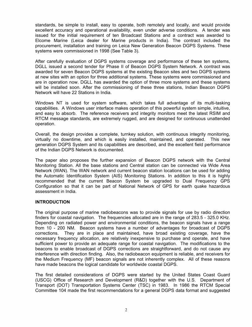
Figure 2: System Block Diagram
6
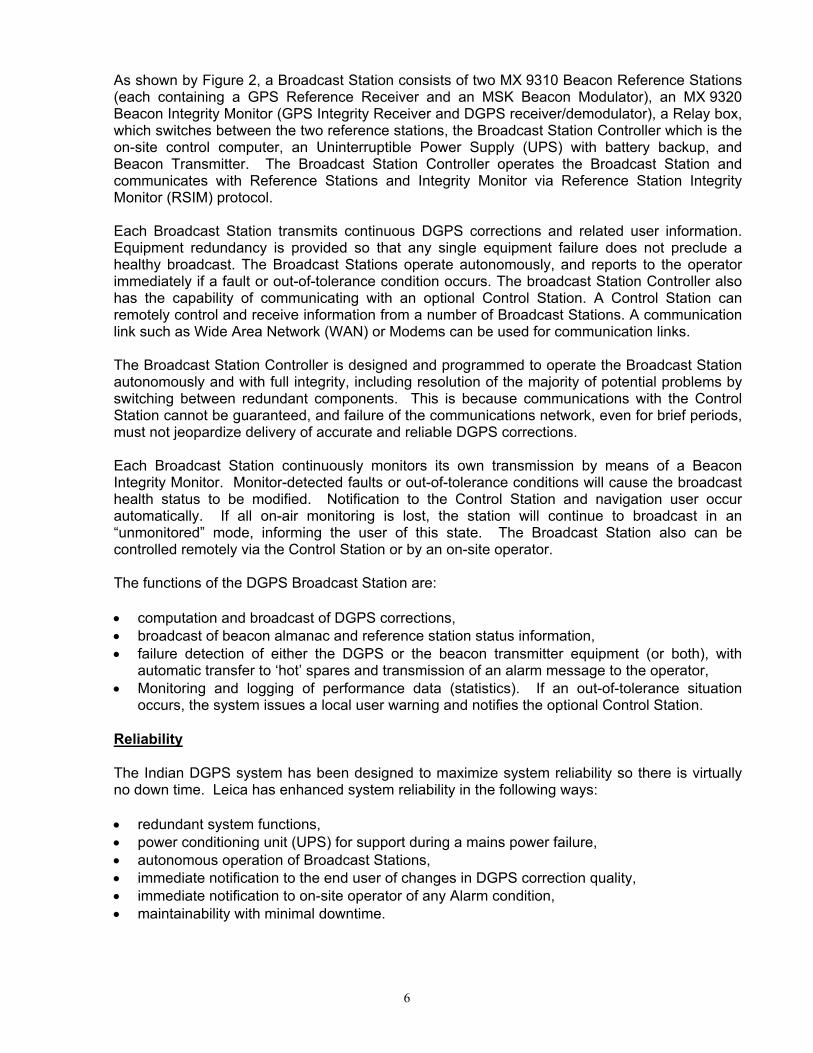
As shown by Figure 2, a Broadcast Station consists of two MX 9310 Beacon Reference Stations (each containing a GPS Reference Receiver and an MSK Beacon Modulator), an MX 9320 Beacon Integrity Monitor (GPS Integrity Receiver and DGPS receiver/demodulator), a Relay box, which switches between the two reference stations, the Broadcast Station Controller which is the on-site control computer, an Uninterruptible Power Supply (UPS) with battery backup, and Beacon Transmitter. The Broadcast Station Controller operates the Broadcast Station and communicates with Reference Stations and Integrity Monitor via Reference Station Integrity Monitor (RSIM) protocol. Each Broadcast Station transmits continuous DGPS corrections and related user information. Equipment redundancy is provided so that any single equipment failure does not preclude a healthy broadcast. The Broadcast Stations operate autonomously, and reports to the operator immediately if a fault or out-of-tolerance condition occurs. The broadcast Station Controller also has the capability of communicating with an optional Control Station. A Control Station can remotely control and receive information from a number of Broadcast Stations. A communication link such as Wide Area Network (WAN) or Modems can be used for communication links. The Broadcast Station Controller is designed and programmed to operate the Broadcast Station autonomously and with full integrity, including resolution of the majority of potential problems by switching between redundant components. This is because communications with the Control Station cannot be guaranteed, and failure of the communications network, even for brief periods, must not jeopardize delivery of accurate and reliable DGPS corrections. Each Broadcast Station continuously monitors its own transmission by means of a Beacon Integrity Monitor. Monitor-detected faults or out-of-tolerance conditions will cause the broadcast health status to be modified. Notification to the Control Station and navigation user occur automatically. If all on-air monitoring is lost, the station will continue to broadcast in an “unmonitored” mode, informing the user of this state. The Broadcast Station also can be controlled remotely via the Control Station or by an on-site operator. The functions of the DGPS Broadcast Station are: • computation and broadcast of DGPS corrections, • broadcast of beacon almanac and reference station status information, • failure detection of either the DGPS or the beacon transmitter equipment (or both), with
automatic transfer to ‘hot’ spares and transmission of an alarm message to the operator, • Monitoring and logging of performance data (statistics). If an out-of-tolerance situation
occurs, the system issues a local user warning and notifies the optional Control Station. Reliability The Indian DGPS system has been designed to maximize system reliability so there is virtually no down time. Leica has enhanced system reliability in the following ways: • redundant system functions, • power conditioning unit (UPS) for support during a mains power failure, • autonomous operation of Broadcast Stations, • immediate notification to the end user of changes in DGPS correction quality, • immediate notification to on-site operator of any Alarm condition, • maintainability with minimal downtime.

7
Redundancy of major functions is fundamental to ensuring that system operation will continue uninterrupted in case of a hardware failure. Each Broadcast Station contains two MX 9310 Beacon Reference Stations, one MX 9320 Beacon Integrity Monitor, one Broadcast Station Controller, and dual Beacon Transmitters. Each Reference Station includes an MSK modulator, which can be switched to feed either beacon transmitter. The MX 9320 Beacon Integrity Monitor continually monitors the quality of the DGPS broadcast by receiving the broadcast corrections, applying them, and comparing the resulting navigation solution to the known position. In this process, the Integrity Monitor monitors GPS satellite availability and geometry, DGPS data correctness and quality, DGPS signal presence, and transmitted power level. When any ‘alarm’ condition is detected, an alarm message is immediately sent to the Broadcast Station Controller for local response and to optional Control Station for remote response. Both Reference Stations remain fully functional and are connected to one of the two transmitters. The equipment set actually transmitting the corrections is referred to as the active or primary unit and the other as the backup or passive unit. The second set of hardware operates as a ‘hot’ backup, which can be activated at any time. If, for any reason, the DGPS broadcast becomes unhealthy, the backup unit is activated manually or automatically from the Broadcast Station Controller using preset criteria. Any failure resulting in a loss of signal to the beacon transmitter or a significant decrease in the output power of the beacon causes the system to switch automatically from transmitter #1 to #2. Since the Broadcast Station Controller monitors the Reference Stations, Integrity Monitors, Modulators, and Transmitters, a failure occurring in any of these is automatically detected. In case of a failure with the CPU or the communication link, the DGPS correction broadcast is maintained. Although the Reference Stations are controlled from the Broadcast Station Controller, they are designed to operate unattended. If a fault occurs which indicates that a change of Reference Station or Beacon Transmitter is required but, due to the fault, cannot occur, then the active Reference Station continues to operate, but in an ‘unhealthy’ state. One important aspect of reliability is ensuring the quality of the DGPS corrections to the end user. A quality indication is provided in the health information broadcast in the RTCM message header. A feedback loop from the Integrity Monitor directly into both Reference Stations is part of the system design. Periodic feedback messages are transmitted from the Integrity Monitor to the Reference Station indicating one of the following conditions: • DGPS Corrections OK • DGPS Out of Tolerance (Reference Station Unhealthy) • Reference Station Unmonitored Results of the feedback input to the Reference Station are reflected in the subsequent RTCM messages broadcast. The DGPS Corrections OK status is transmitted when the Integrity Monitor has reported that the DGPS corrections have passed all quality checks. If the position error at the Integrity Monitor exceeds the user-specified tolerance, the RTCM health status would indicate Reference Station Unhealthy. The Reference Station Unmonitored status can occur for a variety of reasons:
8
• Reference Station is not receiving feedback messages from the Integrity Monitor, • Integrity Monitor is receiving the DGPS information, but cannot validate it, • Reference Station does not receive a feedback message from the Integrity Monitor (at a
minimum of once per hour) which identifies those satellites being tracked at the Integrity Monitor.
In the event that a high residual for a given satellite is detected at the Integrity Monitor, that satellite is re-acquired automatically at both the Reference Station and the Integrity Monitor as part of the automatic feedback function between the Integrity Monitor and the Reference Station. If an anomaly is detected in one of the satellite signals, the periodic feedback is bypassed and the Integrity Monitor generates an immediate message to inform the Reference Station of the condition. Real-time operator messages are part of the system design. Messages indicating impending status changes, poor satellite signals, etc., are user-defined and can be generated at any time. These messages allow the operator to notify DGPS users of important conditions in a timely fashion. Complete integrity of any system also must include the end user. The equipment employed by the end user must be capable of detecting changes in the Reference Station health and informing the user of this condition. Corrections that are not ‘healthy’ should never be applied by the user equipment, and corrections that are ‘unmonitored’ must be carefully reviewed. Unfortunately, some user equipment pays little or no attention to these integrity messages. The shipboard user equipment must provide complete system integrity by system alarms, reporting changes to Reference Station health status, and continually testing for invalid measurements and corrections. The communication protocol within the Broadcast Station between the GPS equipment and the Broadcast Station Controller adheres to the Reference Station Integrity Monitor (RSIM) specification developed by the RTCM and endorsed by IALA. Maintainability from a real-time standpoint is also a feature of this system. The user can command a restart of any of the GPS receivers located at the Broadcast Station. SYSTEM DESIGN - SOFTWARE The Indian DGPS Beacon System is based upon a design that allows flexibility, ease of use, and provides for future expansion. The system supports high level program languages (such as C or Pascal) and has memory map support with memory protection. Database management, password protection, print spooling, multiple tasking, and linkages with external vendor software packages are incorporated into Leica’s approach. Operating System The Windows NT Operating System provides an ideal platform for implementing the Broadcast Station Controller features. Its built-in security, stability, multiple language support, preemptive multi-tasking capabilities, operator interface familiarity among a large base of users, and long-term support from Microsoft makes Windows NT the best choice of Operating Systems for the Indian DGPS Beacon System.

9
Ease of Use The Windows NT documentation includes guidelines for operator interface design and operation, which ensures that operators familiar with other Windows applications will be able to use the software in less time than with competing systems. Windows NT also provides the framework for implementing context-sensitive help in a standard manner. The Indian system has been designed with these principles in mind.
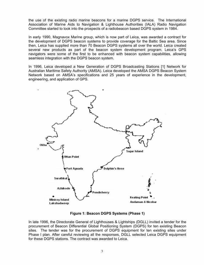
Figure 3: Broadcast Station Overview Window
The Broadcast Station Controller appears as a standard Windows Application to the operator. The familiar menu bar, tool bar, client window, and status bar format is used. Since this is a standard Windows Application, it is possible to change the size or minimize the Main Window. Also, it is possible to run other applications simultaneously while the software continues to perform all real-time functions in the background or while minimized. Standard Windows controls are used for all operator interaction. General overview windows display important system data and traffic light status indicators are used wherever possible to help the operator determine system status at a glance. Figure 3 shows Broadcast Station Overview Window. This window is used to establish the communication with Reference Stations, Integrity Monitor and Relay Switch box. Secondary windows are accessed by a simple mouse click. This allows the operator to inspect various detailed system parameters when required. (Refer Figure 4).
10
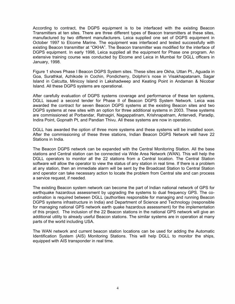
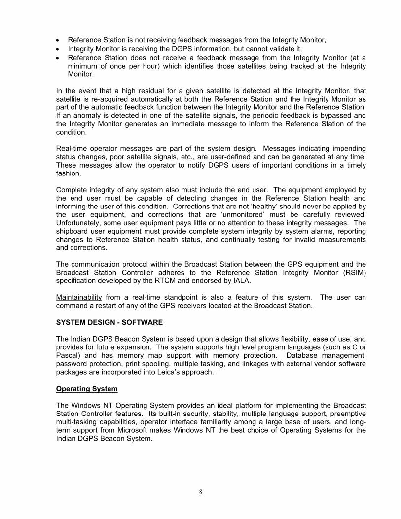
Figure 4: Broadcast Station Detail Window
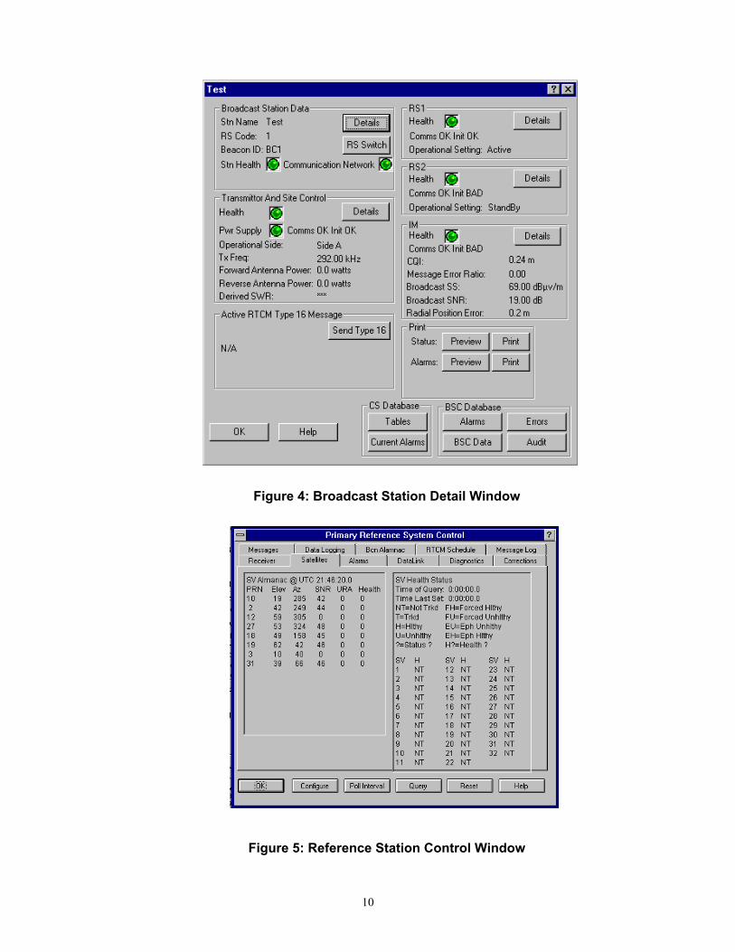
Figure 5: Reference Station Control Window
11
Tab control windows are used to a large extent because of their ability to group data items from a common source in an organized manner. For example, the operator is able to view all data from a Reference Station on a single property sheet containing multiple tabs (refer to Figure 5). This provides an intuitive interface for operator control and inspection. Alarm Display The operator enables specific alarm conditions by using window drop down menus. When the Control Station receives an alarm, a permanent dialog box is displayed until the operator responds, regardless of other current system functions. This dialog contains a list of all alarms, along with a button to acknowledge them. The Alarm window displays the particular alarm condition, origin, duration, and present status. This allows the operator to quickly identify the source of the alarm and take the necessary action. The alarm window remains the foremost window until the alarm condition is acknowledged and rectified. Database Local databases are updated by the Broadcast Station Controllers to obtain status, alarm, and error data. All RSIM data messages for each Broadcast Station Controller are logged and archived to a database on the local hard disk. Alarm data are logged to the Alarm Printer as well as to the Alarm Database.
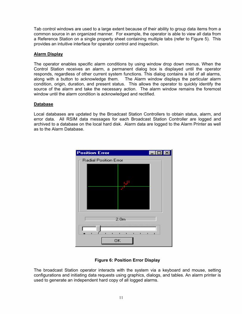
Figure 6: Position Error Display The broadcast Station operator interacts with the system via a keyboard and mouse, setting configurations and initiating data requests using graphics, dialogs, and tables. An alarm printer is used to generate an independent hard copy of all logged alarms.
12
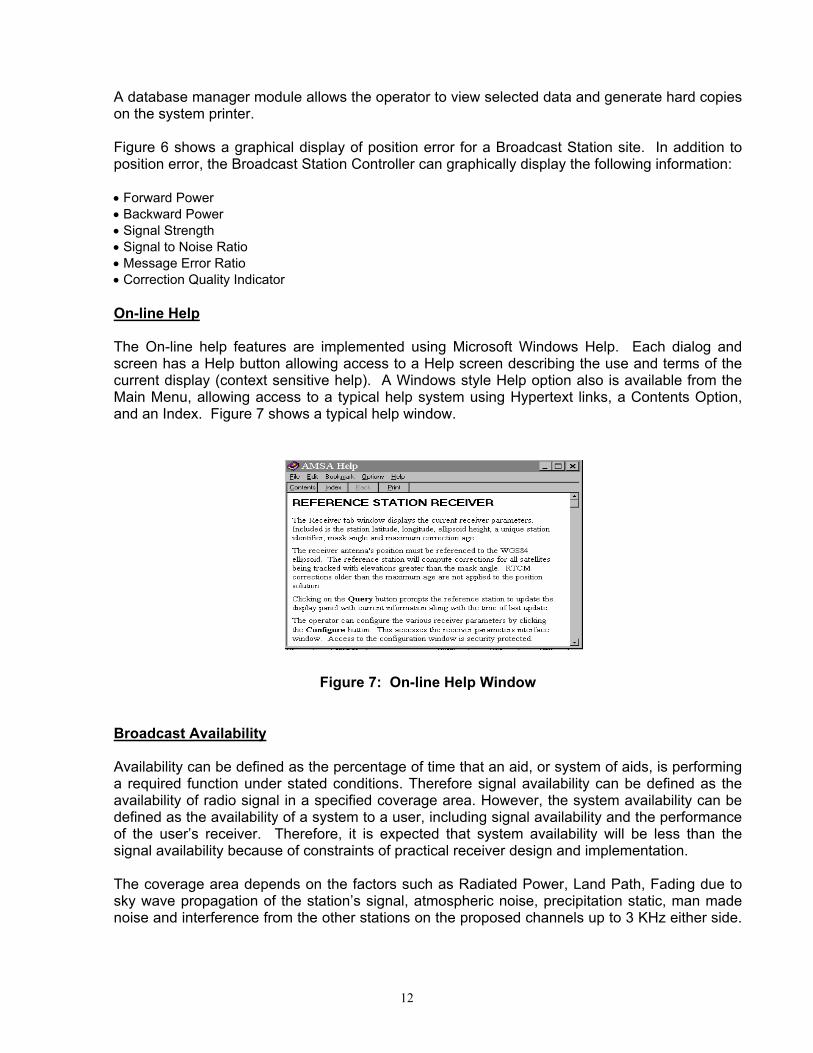
A database manager module allows the operator to view selected data and generate hard copies on the system printer. Figure 6 shows a graphical display of position error for a Broadcast Station site. In addition to position error, the Broadcast Station Controller can graphically display the following information:
• Forward Power • Backward Power • Signal Strength • Signal to Noise Ratio • Message Error Ratio • Correction Quality Indicator On-line Help The On-line help features are implemented using Microsoft Windows Help. Each dialog and screen has a Help button allowing access to a Help screen describing the use and terms of the current display (context sensitive help). A Windows style Help option also is available from the Main Menu, allowing access to a typical help system using Hypertext links, a Contents Option, and an Index. Figure 7 shows a typical help window.
Figure 7: On-line Help Window
Broadcast Availability Availability can be defined as the percentage of time that an aid, or system of aids, is performing a required function under stated conditions. Therefore signal availability can be defined as the availability of radio signal in a specified coverage area. However, the system availability can be defined as the availability of a system to a user, including signal availability and the performance of the user’s receiver. Therefore, it is expected that system availability will be less than the signal availability because of constraints of practical receiver design and implementation. The coverage area depends on the factors such as Radiated Power, Land Path, Fading due to sky wave propagation of the station’s signal, atmospheric noise, precipitation static, man made noise and interference from the other stations on the proposed channels up to 3 KHz either side.

13
Since signal availability is defined in the coverage area, above factors should be considered for the computation of Broadcast Station Signal Availability.
SYSTEM VERIFICATION
Accurate GPS antenna position is important in order to achieve good accuracy, as any error in reference station antenna position will be reflected in user equipment. The antenna positions of Reference Stations and Integrity Monitor antennas were computed by collecting data with Leica dual frequency GPS system and data processing was done by using Bernese software and data from various IGS stations.
In order to verifying the system performance, reference points were surveyed. The results of two stations are shown in Figures 8 and 9. These verifying points are at Dwarka Lighthouse near Okha Beacon Station and at “Elcome House” in Mumbai near Uttan Beacon Station. Leica MX 9400N DGPS Navigator and MX 52R Beacon receiver were used to conduct the tests. Leica IM PC program was used to display the real time bull’s eye plot and statistics.
Figure 8: Radial Position Error Plot - Okha
Table 1 Statistics - Okha Station
Mean Sigma % Out Max Err
North 0.0 0.45 None -2.90
East 0.1 0.49 None 2.42
Up 0.0 0.60 None 30.80
14
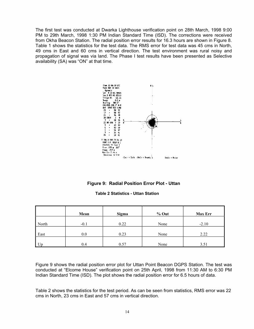
The first test was conducted at Dwarka Lighthouse verification point on 28th March, 1998 9:00 PM to 29th March, 1998 1:30 PM Indian Standard Time (ISD). The corrections were received from Okha Beacon Station. The radial position error results for 16.3 hours are shown in Figure 8. Table 1 shows the statistics for the test data. The RMS error for test data was 45 cms in North, 49 cms in East and 60 cms in vertical direction. The test environment was rural noisy and propagation of signal was via land. The Phase I test results have been presented as Selective availability (SA) was “ON” at that time.
Figure 9: Radial Position Error Plot - Uttan
Table 2 Statistics - Uttan Station
Mean Sigma % Out Max Err
North -0.1 0.22 None -2.10
East 0.0 0.23 None 2.22
Up 0.4 0.57 None 3.51
Figure 9 shows the radial position error plot for Uttan Point Beacon DGPS Station. The test was conducted at “Elcome House” verification point on 25th April, 1998 from 11:30 AM to 6:30 PM Indian Standard Time (ISD). The plot shows the radial position error for 6.5 hours of data.
Table 2 shows the statistics for the test period. As can be seen from statistics, RMS error was 22 cms in North, 23 cms in East and 57 cms in vertical direction.
15
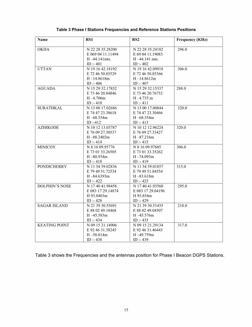
Table 3 Phase I Stations Frequencies and Reference Stations Positions
Name RS1 RS2 Frequency (KHz)
OKHA
N 22 28 35.28200 E 069 04 11.11494 H –44.141mts. ID :- 401
N 22 28 35.24182 E 69 04 11.19083 H –44.141 mts. ID :- 402
296.0
UTTAN
N 19 16 42.18192 E 72 46 50.85529 H –14.8618m ID :- 406
N 19 16 42.09918 E 72 46 50.85366 H –14.8612m ID :- 407
306.0
AGUADA
N 15 29 32.17852 E 73 46 20.84846 H –4.706m ID :- 410
N 15 29 32.15337 E 73 46 20.76752 H –4.735 m ID :- 411
288.0
SURATHKAL
N 13 00 17.02686 E 74 47 23.38618 H –68.354m ID :-412
N 13 00 17.00844 E 74 47 23.30466 H –68.354m ID :- 413
320.0
AZHIKODE
N 10 12 13.03787 E 76 09 27.30537 H –88.2402m ID :- 414
N 10 12 12.96224 E 76 09 27.33427 H –87.216m ID :- 415
320.0
MINICOY
N 8 16 09.95776 E 73 01 33.26505 H –80.934m ID :- 418
N 8 16 09.97605 E 73 01 33.35262 H –74.093m ID :- 419
306.0
PONDICHERRY
N 11 54 59.02836 E 79 49 51.72534 H –84.6393m ID :- 422
N 11 54 59.01857 E 79 49 51.84554 H –83.618m ID :- 423
315.0
DOLPHIN’S NOSE
N 17 40 41.98458 E 083 17 29.14874 H 93.8403m ID :- 428
N 17 40 41.93560 E 083 17 29.04196 H 93.854m ID :- 429
295.0
SAGAR ISLAND
N 21 39 30.55691 E 88 02 49.10468 H –45.583m ID :- 434
N 21 39 30.51435 E 88 02 49.04507 H –45.576m ID :- 435
218.0
KEATING POINT N 09 15 21.14906 E 92 46 31.38245 H –50.814m ID :- 438
N 09 15 21.29134 E 92 46 31.46443 H –49.759m ID :- 439
317.0
Table 3 shows the Frequencies and the antennas position for Phase I Beacon DGPS Stations.

16
Table 4 Phase II Stations Frequencies and Reference Stations Positions
Name RS1 RS2 Frequency (KHz)
PORBANDAR
N 21 37 21.219430 E 069 37 12.003770
N 21 37 21.291790 E 069 37 11.968630
293.0
RATNAGIRI
N 16 59 16.373760 E 73 16 20.599300
N 16 59 16.46630 E 73 16 20.485350
308.0
NAGAPPATINAM
N 10 45 58.133290 E 79 51 00.372440
N 10 45 58.036090 E 79 51 00.376190
323.0
KRISHNAPATNAM
N 14 15 17.533210 E 80 07 33.235470
N 14 15 17.464800 E 80 07 33.358240
297.0
PANDIAN THIVU
N 08 47 08.912560 E 78 11 48.559720
N 08 47 08.898860 E 78 11 48.363840
309.0
PARADIP
N 20 15 21.040350 E 86 39 19.882780
N 20 15 21.963630 E 86 39 19.693780
290.0
ANTERVEDI
N 16 19 01.118650 E 81 43 32.844620
N 16 19 01.138110 E 81 43 32.700830
320.0
INDIRA PT
N 06 45 20.75228 E 93 49 40.22758
N 06 45 20.74367 E 93 49 40.30665
303.0
GOPNATH PT
N 21 12 11.879410 E 72 06 31.199050
N 21 12 11.7515390 E 72 06 31.160800
299.0
Table 4 shows the Frequencies and the antennas position for Phase II Beacon DGPS Stations. The three additional stations are to be installed at HAZIRA (312.0 KHz), PULICAT (319.0 KHz), and EAST ISLAND (313.0 KHz).
ADDITIONAL FEATURES
Leica has enhanced the Broadcast Station Controller software for customers such as India DGLL and China MSA so that all Control Station functions are available at the Broadcast Station Controller. Additional features were implemented for Phase II systems. Real Time Display Time Series
Real-time display of time series graphs with complete operator control for forward power, backward power, signal strength, signal-to-noise ratio, message error ratio, radial position error, and correction quality indicator (see Figure 10).

17
Figure 10: Real Time Series Plot
Figure 11: Real-time Radial Position Error Plot
18
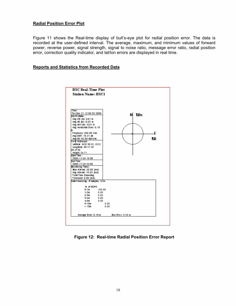
Radial Position Error Plot
Figure 11 shows the Real-time display of bull’s-eye plot for radial position error. The data is recorded at the user-defined interval. The average, maximum, and minimum values of forward power, reverse power, signal strength, signal to noise ratio, message error ratio, radial position error, correction quality indicator, and lat/lon errors are displayed in real time.
Reports and Statistics from Recorded Data
Figure 12: Real-time Radial Position Error Report
19
The new system has been designed to generate five types of reports from the recorded data. These reports give the information on system performance. The following types of reports can be generated:
1. Statistics report from the data for user selected interval
2. Daily report from the recorded data
3. Monthly report from the recorded data
4. Out of threshold position error report
5. Real time plot report from selected data
Figure 12 shows a sample of the real-time radial position error plot report.
EXPANSION OF DGPS NETWORK
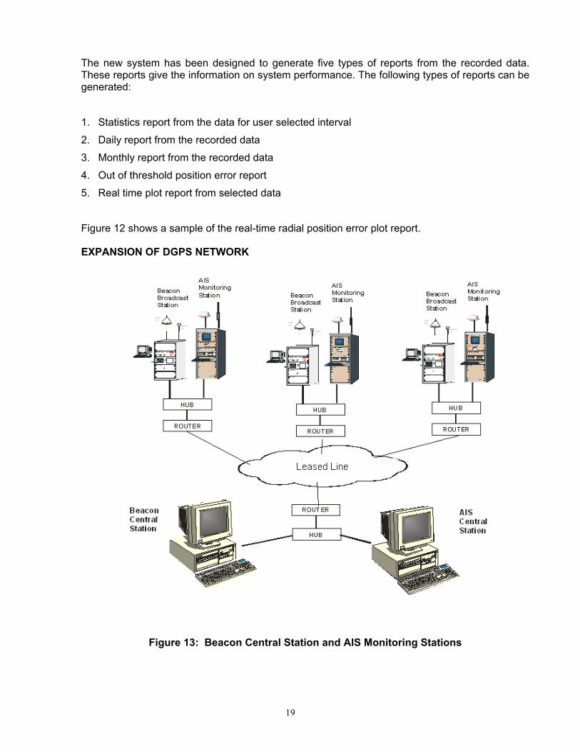
Figure 13: Beacon Central Station and AIS Monitoring Stations

20
With the completion of three more stations, India will have a network of 22 stations. These stations can be monitored and controlled from a central location with Leica Central Station (CS) software. All the Broadcast stations are connected via a Wide Area Network (WAN). A Central Station PC with CS software is located at the monitoring site and connected to WAN network. The operator at the central site can monitor all the stations. If there is an alarm at any Broadcast Station, then the alarm is automatically sent by Broadcast Station PC to Central Station. The alarm is displayed on the Central Station PC and operator can take necessary action to locate and rectify the fault. If necessary, a service call is made by operator to maintenance staff. Leica has supplied similar systems to Australia Maritime Safety Authority, Australia, Portnet, South Africa, Royal Hydrography Institute, Denmark, Institute of Hydrography office, Portugal and many other countries.
The existing Beacon system network should become part of Indian national network of GPS for earthquake hazardous assessment by upgrading the system to dual frequency GPS. The inclusion of these 22 Beacon stations in the national GPS network will give an additional utility to already useful Beacon Stations.
The beacon broadcast stations can also be upgraded with the Automatic Identification System (AIS) Monitoring Stations. AIS monitoring stations can monitor and display all the ships, which are equipped with AIS transponders. These monitoring stations can be located with the Beacon DGPS stations and can be connected to same WAN network. A Central monitoring station for AIS can also be located at Beacon CS site.
CONCLUSION
This paper describes a latest new generation Leica Beacon DGPS Systems Network, which has been supplied to Department of Lighthouses & Lightships (DGLL) to meet their requirements. The system is simple and easy to use. Because of the intuitive nature of the Windows NT software for the Broadcast Station Controller, it is easy to learn and use by the operators.
The verification test results at two sites have shown that sub-meter accuracy was achieved even in the noisy environment.
There are several important information which have been discussed in this paper:
1. The new generation of Leica DGPS Beacon Systems now being used by DGLL meets rigorous standards of reliability, maintainability, ease of installation, ease of use, accuracy, and integrity.
2. Navigation users should not assume that all DGPS user equipment is equivalent. There are large variations regarding: GPS multi-path mitigation, beacon signal sensitivity, mitigation of impulsive noise in the beacon frequency band, alarms to the operator when age of DGPS corrections is excessive or when warning messages are received, and direct access to Beacon System warning messages. To preserve integrity, a DGPS navigator should make it clear whether the navigation solution is fully trustworthy or not. These issues are vital and can make the difference between tragedy and safety of life at sea.
3. The system availability is expected to be less than the signal availability because of constraints of practical receiver design and implementation. The coverage area depends on the factors such as Radiated Power, Land Path, Fading due to sky wave propagation of the station’s signal, atmospheric noise, precipitation static, man made noise and interference from the other stations on the proposed channels up to 3 KHz either side.
21
The above factors should be taken in to account while determine the coverage area of the transmission.
4. One of the important features of the Beacon DGPS system is that it checks the integrity of the transmitted corrections in real time. The Integrity monitors keeps on sending the status information to both the reference stations at a rate selected by operator. If Integrity Monitor finds that the correction of a satellite is not good, then the reference station does not transmit the correction of that satellites and user equipment position is not affected. This is the reason that IALA, USCG and other international organizations have recommended the use of Beacon DGPS systems even after the Selective Availability have been discontinued.
5. The existing Beacon system network should become part of Indian national network of GPS for earthquake hazardous assessment by upgrading the system to dual frequency GPS. The co-ordination is required between DGLL (authorities responsible for managing and running Beacon DGPS systems infrastructure in India) and Department of Science and Technology (responsible for managing national GPS network earth quake hazardous assessment) for the implementation of this project. The inclusion of these 22 Beacon stations in the national GPS network will give an additional utility to already useful Beacon Stations.
6. All the Broadcast Stations can be connected via Wide Area Network to a Central Control PC at a central location. All the Stations can be monitored by the operator at central site. The broadcast stations sites can also be equipped with Automatic Identification Systems (AIS) Monitoring Stations for monitoring the ships equipped with AIS transponders.
REFERENCES [1] Franko R, Mittal S, Stansell T, Harris R, D’Amico E, & Cannon S, A New Generation of DGPS Broadcasting Stations, ION GPS Conference in Nashville, USA, September 1998. Microsoft, Windows, and Windows NT are either registered trademarks or trademarks of the Microsoft Corporation in the United States and/or other countries.