india version 1.0 july 2005 - greenhouse gas protocol | tool guidance document india version 1.0 •...
TRANSCRIPT
CEMENT SECTOR EMISSIONS
CALCULATION TOOL:
India Version 1.0
July 2005
Background This tool has been developed by The Energy and Resources Institute (TERI), New Delhi through a multi-stakeholder consultative process to incorporate the needs and objectives of key stakeholders in the cement sector. The United States Environmental Protection Agency (US EPA) has funded development of this tool, and provided technical guidance throughout the development process. The tool is based upon the existing Corporate Greenhouse Gas (GHG) Inventory Protocol and tools developed by the World Resources Institute (WRI), a Washington-based NGO, and World Business Council for Sustainable Development (WBCSD), a Geneva-based coalition of international companies under their GHG Protocol initiative1. Following review by a panel of domestic and international cement sector experts, Version 1.0 of the tool is now available for use by the Indian cement industry.
1 The Greenhouse Gas (GHG) Protocol initiative is a multi-stakeholder partnership of business, non-governmental organizations (NGOs), governments, and others convened by the World Resources Institute (WRI), a US-based environmental NGO, and the World Business Council for Sustainable Development (WBCSD), a Geneva-based coalition of 170 international companies. Launched in 1998, the initiative’s mission is to develop internationally accepted GHG accounting and reporting standards for business and to promote their broad adoption.

Cement Tool Guidance Document India Version 1.0
Table of Contents
1 Introduction ........................................................................................................4 1.1 PURPOSE AND SCOPE............................................................................................................................ 4 1.2 OTHER EXISTING EMISSIONS QUANTIFICATION TOOLS .................................................................. 5
2 Customized cement sector tool for India ...........................................................6 2.1 OVERVIEW OF THE CUSTOMIZED CEMENT TOOL ............................................................................ 6 2.2 CRITERIA FOR DEVELOPING THE TOOL............................................................................................. 6 2.3 THE CONCEPT OF ‘SCOPE’.................................................................................................................... 7 2.4 SCOPE 1: DIRECT AIR EMISSIONS ........................................................................................................ 7
2.4.1 Direct process air emissions......................................................................................................... 9 2.4.2 Direct stationary combustion..................................................................................................... 13 2.4.3 Direct mobile combustion ......................................................................................................... 14 2.5 SCOPE 2: INDIRECT GREENHOUSE GAS EMISSIONS ........................................................................ 15 2.6 SCOPE 3: INDIRECT CARBON DIOXIDE EMISSIONS DUE TO CLINKER IMPORTED BY THE PLANT 16 2.7 EQUITY AND CONTROL ISSUES IN CORPORATE-LEVEL GHG REPORTING................................. 16
2.7.1 Equity share approach ............................................................................................................ 16 2.7.2 Control approach.................................................................................................................... 16
3 Customized cement tool instructions ............................................................... 17 3.1 STRUCTURE OF CUSTOMIZED TOOL.................................................................................................. 17 3.2 STEP-BY-STEP INSTRUCTIONS FOR COMPLETING THE SPREADSHEET ......................................... 18
4 Internal reporting and documentation ............................................................. 27 4.1 DATA SOURCE...................................................................................................................................... 27 4.2 MONITORING AND VERIFICATION ................................................................................................... 27
5 References ......................................................................................................... 27
6 Acknowledgements ........................................................................................... 28
7 Contributors ...................................................................................................... 28
A. Appendix ........................................................................................................... 30
2
Cement Tool Guidance Document India Version 1.0
Tables and figures
Table 2.1 Parameters and proposed data sources for calculation of direct carbon dioxide emissions 8 Table 2.2 Default values (to be used only if plant-specific values are not available).......................... 12 Table 2.3 Parameters and proposed data sources for calculation of indirect carbon dioxide
emissions ........................................................................................................................................ 15 Table 2.4 Grid-specific emission factors for different grids ................................................................. 15 Table 3.1 Purpose of the different worksheets....................................................................................... 17 Table A.1 State-wise default CO2 emission factor for clinker and CO2 emission factor for clinker kiln
dust ................................................................................................................................................. 31
3
Cement Tool Guidance Document India Version 1.0
1 Introduction
The customized India-specific cement sector tool presents a simple approach for inventories of basic air emissions from a cement facility, which can then be extended to the corporate level. The tool is an ‘integrated air emissions’ calculation tool that could help inform decision-making for air quality management (AQM): both for greenhouse gas (GHG) mitigation as well as criteria air pollutants. Utilizing user-friendly spreadsheets, the tool facilitates calculation of direct and indirect carbon dioxide (CO2) emissions and direct sulphur dioxide (SO2) emissions from cement plants. Although sector-specific tools for GHG inventorization had been developed internationally, there was an unmet need to customize and simplify the international calculation tools for Indian industry; this tool is a step in that direction. A simplified emissions measurement tool for India is expected to gain better acceptability among the Indian cement industry due to improved consistency and accuracy in the measurement of source-specific emissions by local businesses and stakeholders.
Before using this tool, users are encouraged to refer to the revised edition of The Greenhouse Gas Protocol: a corporate accounting and reporting standard2 which gives in detail the emissions accounting principles, guidelines for setting boundaries, and other related aspects. While this document focuses on GHGs, the principles are also generally applicable to source-level quantification of conventional pollutants. Below, the purpose and scope of the customized tool (excel-based worksheets) is described and instructions are provided for completing the different accompanying worksheets.
1.1 Purpose and scope
Air pollution and climate change have come to be recognized as key sustainable development issues. Many companies are making efforts to manage and reduce air emissions through regulatory requirements or emerging voluntary programmes being promoted by national governments. As a result, companies must be able to understand and manage their air emissions if they are to ensure long-term success in a competitive business environment, and have the capacity to address both current and potential future pollution and climate change policies. A well-designed and maintained corporate emissions inventory facilitated by this tool can serve several business goals for Indian companies, including 2 The Corporate Accounting and Reporting Standard has been developed under the GHG (greenhouse gas) Protocol Initiative. The document provides a step-by-step guide for companies for quantifying and reporting their GHG emissions. It covers the accounting and reporting of the six GHGs covered by the Kyoto Protocol – carbon dioxide (CO2), methane (CH4), nitrous oxide (N2O), hydrofluorocarbons (HFCs), perfluorocarbons (PFCs), and sulphur hexafluoride (SF6). This document can be downloaded from www.ghgprotocol.org.
4
Cement Tool Guidance Document India Version 1.0
• managing air emissions and identifying reduction opportunities; • forming compliance strategies for air emissions regulatory programmes; • public reporting and participation in voluntary air emissions programmes; • participating in market-based mechanisms; and • recognition for early voluntary AQM action.
In India, the cement sector is one of the prominent contributors to conventional and GHG emissions. Although there is no statutory obligation on companies to measure and report total air emissions in India, the preparation of air emission inventories can be useful in internal company benchmarking, public reporting, product profiles, and emerging emissions trading. In the near future, it is also possible that voluntary actions to promote energy efficiency and GHG emissions mitigations, especially in large, organized industrial sectors like cement will gain momentum. This calculation tool facilitates cement plants in adopting a common and simplified approach for inventorizing their air emissions by inserting the commonly collected data in various worksheets — the tool automatically calculates these emissions using internationally accepted methodologies.
1.2 Other existing emissions quantification tools
There are many protocols for estimating and reporting air emissions. Most of the existing protocols are based on a common set of general principles with differences primarily attributable to the differing purposes of the protocols (e.g., national inventories, corporate inventories, project accounting, etc.). The general principles for air inventory development are important and need to be addressed while preparing any inventory. This document, however, devotes relatively little attention to such issues because these principles are generic, and information is available in a variety of other documents as described below. Some especially helpful sources of general information on inventory preparation are as follows.
• The Intergovernmental Panel on Climate Change (IPCC) Guidelines for national GHG inventories under the United Nations Framework Convention on Climate Change (UNFCCC)3
• The Emission Inventory Improvement Program (EIIP)4 • The World Resources Institute/World Business Council for Sustainable
Development (WRI/WBCSD) Initiative for Corporate GHG Reporting5
3 Revised 1996 Guidelines for National Greenhouse Gas Inventories (see IPCC 1996), and Good Practice Guidance and Uncertainty Management in National Greenhouse Gas Inventories (see IPCC 2000, <htpp://www.ipcc-nggip.iges.or.jp>) 4 The Emission Inventory Improvement Program (EIIP) is a jointly sponsored effort of the State and Territorial Air Pollution Programme Administrators/Association of Local Air Pollution Control Officials (STAPPA/ALAPCO) and EPA. For technical documents and guidance, see http://www.epa.gov/ttn/chief/eiip/index.html 5 http://www.ghgprotocol.org
5
Cement Tool Guidance Document India Version 1.0
• Climate Leaders (United States Environmental Protection Agency (USEPA) GHG inventory protocol for direct emission from the cement sector.6
• Air Pollution Training Institute7 The WRI/WBCSD and Climate Leaders documents are especially relevant for companies using these calculation tools because they focus on company-level reporting. While these guidance documents focus solely on GHGs, they provide helpful information on the following broadly applicable issues.
• Air emissions accounting and reporting principles (e.g. organizational and operational boundary determination, relevance, completeness, consistency, transparency, and accuracy)
• Defining corporate objectives for inventories (e.g. public reporting, voluntary initiatives, and carbon trading)
• Establishing baselines and accounting for reductions • Managing inventory quality • Verification
2 Customized cement sector tool for India
2.1 Overview of the customized cement tool
Air emissions in a cement plant can be classified broadly into two categories: direct emissions and indirect emissions. Direct emissions are from sources owned or controlled by the reporting company such as process emissions, stationary combustion, and mobile sources. Indirect emissions are associated with sources that are not owned or controlled by the reporting company such as electricity purchased or clinker imports. This cement tool can be used to estimate both the direct and indirect sources of GHG emissions and the direct SO2 emissions from facilities.8
2.2 Criteria for developing the tool
The tool has been designed to meet the following criteria:
1. Be consistent, transparent, and credible; 2. Cover all major emission sources; 3. Be applicable to processes used in Indian cement industry;
6 http://www.epa.gov/climateleaders/ 7 http://epa.gov/air/oaqps/eog/index.html 8 Few of the international greenhouse gas emission tools also have provision for estimating indirect emissions from activities such as extraction and production of purchased materials, transportation of purchased fuels, clinker imports, and use of sold products or services. Provisions for estimating emissions from these indirect sources (except indirect carbon dioxide emissions due to clinker imported by the plant) have not been included in this tool.
6
Cement Tool Guidance Document India Version 1.0
4. Be used to estimate direct process emissions based on both cement production and clinker production;
5. Allow reporting of emissions in absolute terms.
2.3 The concept of ‘scope’
For accounting and reporting purposes, air emissions are usually categorized into ‘scopes’. Scopes 1, 2, and 3 have been defined as follows.9
Scope 1: Direct air emissions from sources that are owned or controlled by the company These include direct process emissions (e.g. calcination of raw materials), direct stationary
combustion in furnaces, diesel generator sets, etc., from fossil fuels, and mobile emissions from company-owned vehicles.
Note that direct CO2 emissions from combustion of biomass, although included in Scope 1
calculation spreadsheet, are reported separately in the summarized plant-level GHG inventory, as biomass combustion is considered to be carbon neutral.
Scope 2: Indirect air emissions from the generation of purchased electricity consumed by the company
Scope 3: Other indirect air emissions from sources not owned or controlled by the facility like
extraction and production of purchased materials, transportation of purchased fuels, clinker imports, and use of sold products and services
Scope 3 is an optional reporting category. Air emissions from Scope 1 and Scope 2 activities have been included in the present tool.
Scope 3 GHG emissions (except for the case where a plant is importing clinker for producing cement) have been excluded from this tool.
2.4 Scope 1: Direct air emissions
In a cement plant, direct air emissions result from the following sources.
i. Direct process: mainly from calcination of limestone, the primary raw material in the manufacture of clinker
ii. Direct stationary combustion - Direct emissions from fossil fuel combustion - Direct emissions from combustion of biomass-based fuels
9 Typically, regulatory programs – whether regulatory or voluntary – only target direct emissions. However, the calculation of indirect emissions is included here so companies can use this information to identify opportunities for environmental improvement.
7
Cement Tool Guidance Document India Version 1.0
iii. Direct mobile combustion: fuel combustion from different mobile sources like trucks, dumpers, cars/buses, or any other mobile source owned by the company
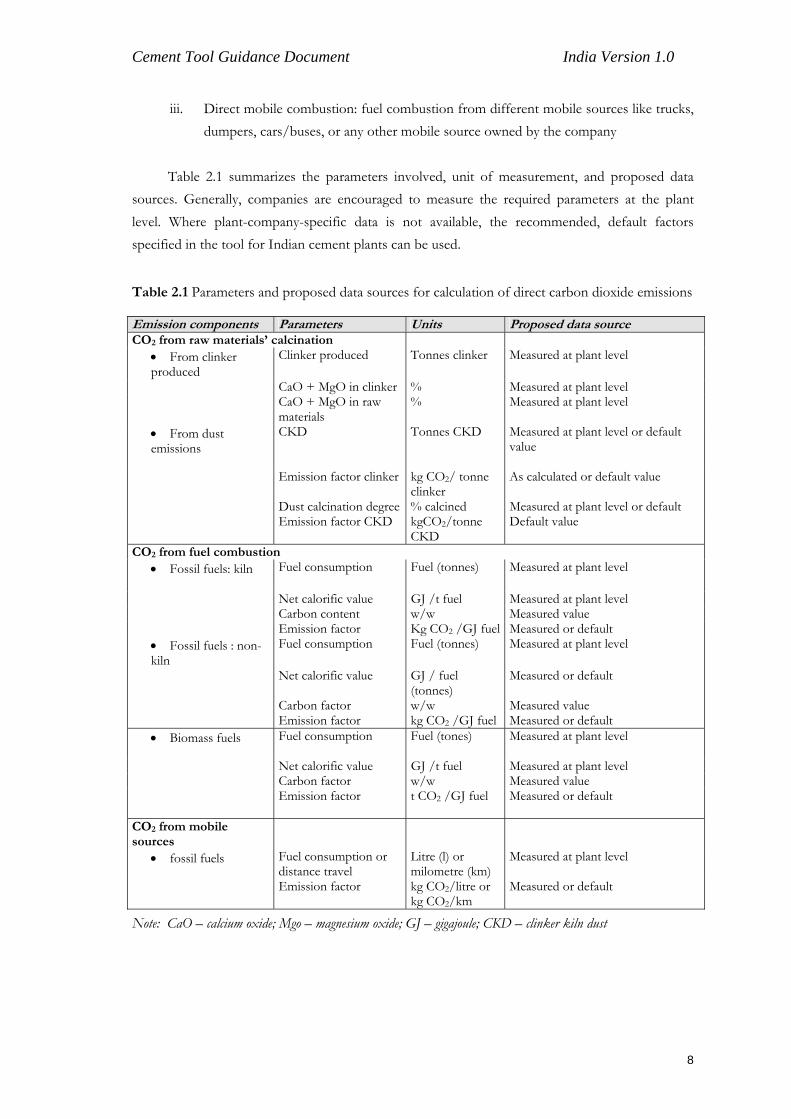
Table 2.1 summarizes the parameters involved, unit of measurement, and proposed data sources. Generally, companies are encouraged to measure the required parameters at the plant level. Where plant-company-specific data is not available, the recommended, default factors specified in the tool for Indian cement plants can be used.
Table 2.1 Parameters and proposed data sources for calculation of direct carbon dioxide emissions
Emission components Parameters Units Proposed data source CO2 from raw materials’ calcination
• From clinker produced
Clinker produced Tonnes clinker Measured at plant level
CaO + MgO in clinker % Measured at plant level CaO + MgO in raw
materials % Measured at plant level
• From dust emissions
CKD Tonnes CKD Measured at plant level or default value
Emission factor clinker kg CO2/ tonne clinker
As calculated or default value
Dust calcination degree % calcined Measured at plant level or default Emission factor CKD kgCO2/tonne
CKD Default value
CO2 from fuel combustion • Fossil fuels: kiln
Fuel consumption Fuel (tonnes)
Measured at plant level
Net calorific value GJ /t fuel Measured at plant level Carbon content w/w Measured value Emission factor Kg CO2 /GJ fuel Measured or default
• Fossil fuels : non-kiln
Fuel consumption Fuel (tonnes)
Measured at plant level
Net calorific value GJ / fuel (tonnes)
Measured or default
Carbon factor w/w Measured value Emission factor kg CO2 /GJ fuel Measured or default
• Biomass fuels Fuel consumption Fuel (tones)
Measured at plant level
Net calorific value GJ /t fuel Measured at plant level Carbon factor w/w Measured value Emission factor t CO2 /GJ fuel Measured or default
CO2 from mobile sources
• fossil fuels Fuel consumption or distance travel
Litre (l) or milometre (km)
Measured at plant level
Emission factor kg CO2/litre or kg CO2/km
Measured or default
Note: CaO – calcium oxide; Mgo – magnesium oxide; GJ – gigajoule; CKD – clinker kiln dust
8
Cement Tool Guidance Document India Version 1.0
2.4.1 Direct process air emissions
a) Carbon dioxide
Calcination is the release of CO2 from carbonates during pyro-processing of the raw mix. Calcination CO2 is directly linked with clinker production. In addition, calcined cement kiln dust (CKD), which is finally released from the stack also accounts for CO2 emissions. These emissions are to be reported as process emissions within Scope 1. Because the primary source of GHGs from cement production is clinker, it is recommended that the companies estimate the CO2 emissions from the process using the clinker production data and CaO/MgO content of the clinker from their facilities. Only in exceptional cases where the clinker production data is not available (which is normally not the case for most of the cement plants in India), clinker production can be estimated indirectly from the cement production data. Therefore, the choice of method to be used for estimating GHG emissions within the cement production industry is dependent on data availability. The two methods are given below.
Method 1: This method is based on the actual clinker produced and the use of this method is recommended for calculating the process-based emissions.
Method 2: This method is based on actual cement production in the facility and should be used only in cases where data on actual clinker production is not available.
The approach used in the clinker-based methodology is based on the WBCSD cement protocol, which calculates calcination CO2 using clinker produced and discarded dust (in principle, the suggested methodology under IPCC guidelines) while the cement-based methodology is based on the Climate Leaders GHG Inventory Protocol, that calculates calcination CO2 from quantity and composition of raw mix consumed. The calculation methods used here differ slightly from those used in IPCC guidance, for example, the clinker-based methodology includes magnesium oxide (MgO) as well as calcium oxide (CaO) inputs in calculation of the emission factor for clinker. Importantly, however, the results obtained by using either of these methods given in the customized tool will be approximately identical to those obtained using the IPCC guidelines.
Method 1: Clinker-based methodology
The clinker-based approach calculates emissions from cement production based on the amount of clinker produced and the CaO and MgO content of the clinker.
This method involves estimating process-related CO2 emissions from cement production. The procedure is given below.
9
Cement Tool Guidance Document India Version 1.0
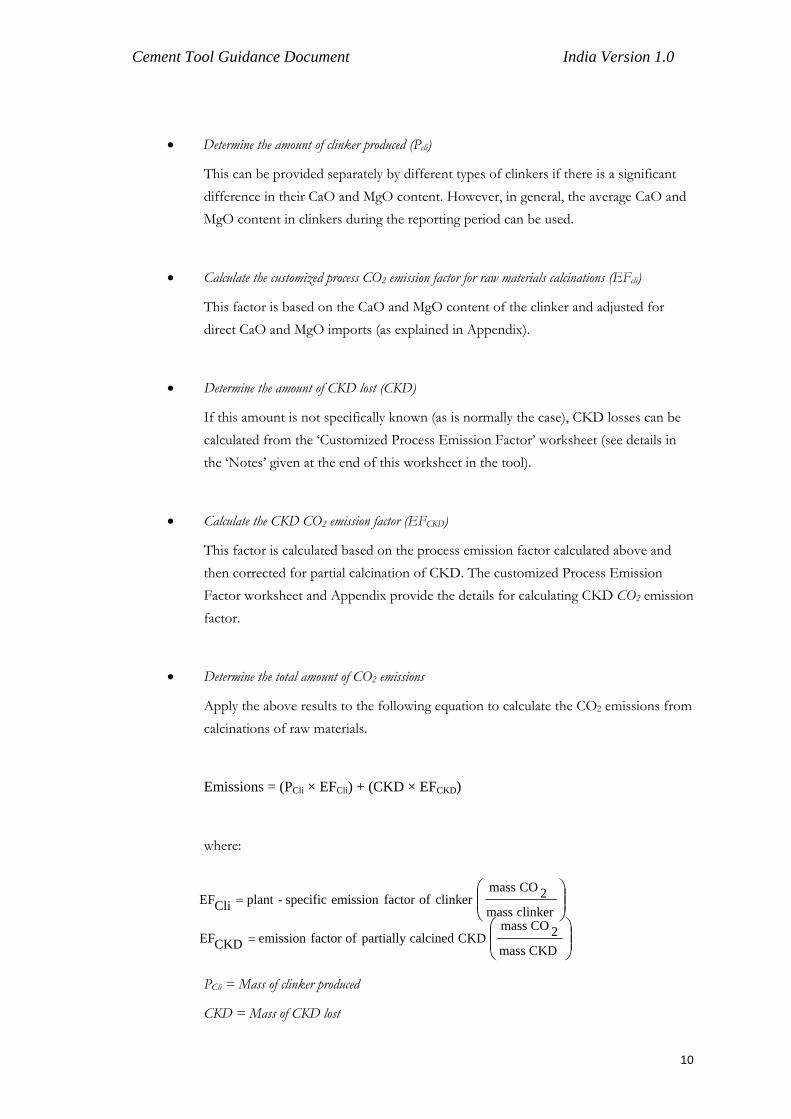
• Determine the amount of clinker produced (Pcli)
This can be provided separately by different types of clinkers if there is a significant difference in their CaO and MgO content. However, in general, the average CaO and MgO content in clinkers during the reporting period can be used.
• Calculate the customized process CO2 emission factor for raw materials calcinations (EFcli)
This factor is based on the CaO and MgO content of the clinker and adjusted for direct CaO and MgO imports (as explained in Appendix).
• Determine the amount of CKD lost (CKD)
If this amount is not specifically known (as is normally the case), CKD losses can be calculated from the ‘Customized Process Emission Factor’ worksheet (see details in the ‘Notes’ given at the end of this worksheet in the tool).
• Calculate the CKD CO2 emission factor (EFCKD)
This factor is calculated based on the process emission factor calculated above and then corrected for partial calcination of CKD. The customized Process Emission Factor worksheet and Appendix provide the details for calculating CKD CO2 emission factor.
• Determine the total amount of CO2 emissions
Apply the above results to the following equation to calculate the CO2 emissions from calcinations of raw materials.
Emissions = (PCli × EFCli) + (CKD × EFCKD)
where:
⎟⎟⎠
⎞⎜⎜⎝
⎛=
clinker mass
2CO massclinker offactor emission specific-plant CliEF
⎟⎟⎠
⎞⎜⎜⎝
⎛=
CKD mass2CO mass
CKD calcinedpartially offactor emission CKDEF
PCli = Mass of clinker produced
CKD = Mass of CKD lost
10
Cement Tool Guidance Document India Version 1.0
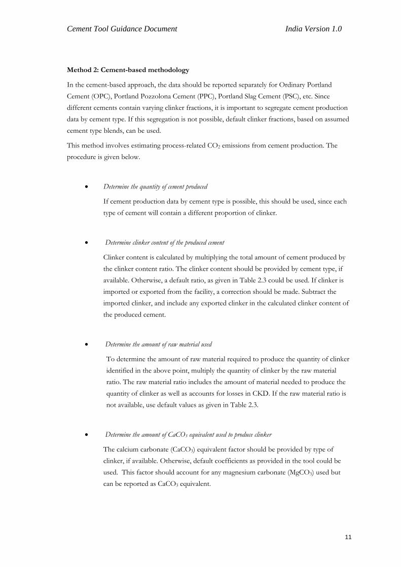
Method 2: Cement-based methodology
In the cement-based approach, the data should be reported separately for Ordinary Portland Cement (OPC), Portland Pozzolona Cement (PPC), Portland Slag Cement (PSC), etc. Since different cements contain varying clinker fractions, it is important to segregate cement production data by cement type. If this segregation is not possible, default clinker fractions, based on assumed cement type blends, can be used.
This method involves estimating process-related CO2 emissions from cement production. The procedure is given below.
• Determine the quantity of cement produced
If cement production data by cement type is possible, this should be used, since each type of cement will contain a different proportion of clinker.
• Determine clinker content of the produced cement
Clinker content is calculated by multiplying the total amount of cement produced by the clinker content ratio. The clinker content should be provided by cement type, if available. Otherwise, a default ratio, as given in Table 2.3 could be used. If clinker is imported or exported from the facility, a correction should be made. Subtract the imported clinker, and include any exported clinker in the calculated clinker content of the produced cement.
• Determine the amount of raw material used
To determine the amount of raw material required to produce the quantity of clinker identified in the above point, multiply the quantity of clinker by the raw material ratio. The raw material ratio includes the amount of material needed to produce the quantity of clinker as well as accounts for losses in CKD. If the raw material ratio is not available, use default values as given in Table 2.3.
• Determine the amount of CaCO3 equivalent used to produce clinker
The calcium carbonate (CaCO3) equivalent factor should be provided by type of clinker, if available. Otherwise, default coefficients as provided in the tool could be used. This factor should account for any magnesium carbonate (MgCO3) used but can be reported as CaCO3 equivalent.
11
Cement Tool Guidance Document India Version 1.0
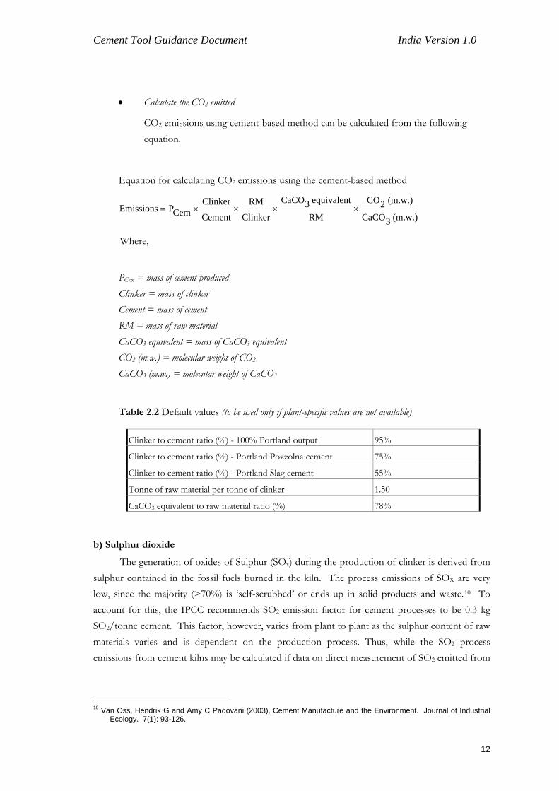
• Calculate the CO2 emitted
CO2 emissions using cement-based method can be calculated from the following equation.
Equation for calculating CO2 emissions using the cement-based method
(m.w.) 3CaCO
(m.w.) 2CO
RM
equivalent 3CaCO
Clinker
RM
Cement
ClinkerCemPEmissions ××××=
Where,
PCem = mass of cement produced Clinker = mass of clinker Cement = mass of cement RM = mass of raw material CaCO3 equivalent = mass of CaCO3 equivalent CO2 (m.w.) = molecular weight of CO2
CaCO3 (m.w.) = molecular weight of CaCO3
Table 2.2 Default values (to be used only if plant-specific values are not available)
Clinker to cement ratio (%) - 100% Portland output 95%
Clinker to cement ratio (%) - Portland Pozzolna cement 75%
Clinker to cement ratio (%) - Portland Slag cement 55%
Tonne of raw material per tonne of clinker 1.50
CaCO3 equivalent to raw material ratio (%) 78%
b) Sulphur dioxide
The generation of oxides of Sulphur (SOx) during the production of clinker is derived from sulphur contained in the fossil fuels burned in the kiln. The process emissions of SOX are very low, since the majority (>70%) is ‘self-scrubbed’ or ends up in solid products and waste.10 To account for this, the IPCC recommends SO2 emission factor for cement processes to be 0.3 kg SO2/tonne cement. This factor, however, varies from plant to plant as the sulphur content of raw materials varies and is dependent on the production process. Thus, while the SO2 process emissions from cement kilns may be calculated if data on direct measurement of SO2 emitted from
10 Van Oss, Hendrik G and Amy C Padovani (2003), Cement Manufacture and the Environment. Journal of Industrial
Ecology. 7(1): 93-126.
12

Cement Tool Guidance Document India Version 1.0
the kiln stack is available, process emission estimates based on fuel characteristics are not included in this version of the tool.
2.4.2 Direct stationary combustion
a) CO2 from fossil fuel combustion
CO2 from conventional fossil kiln fuels (coal, lignite, petcoke, fuel oil, and natural gas) is calculated based on fuel consumption, net calorific values, and CO2 emission factors. Fuel consumption and net calorific values of fuels are routinely measured at plant level. Net calorific value and percentage of carbon contents are calculated by proximate and ultimate analysis of fuel respectively. CO2 emission factors for fossil fuels can be calculated from the ‘Custom Combustion Emission Factor’ worksheet provided in the tool. If the quality of coal used in kiln, pre-calcinator, captive power plant, etc., is different, the CO2 emission factor for different qualities of coal should be calculated separately in the worksheet. Generally, IPCC recommends accounting for incomplete combustion of fossil fuels. In cement kilns, however, this effect is negligible, due to very high combustion temperatures and long residence time in kilns, and minimal residual carbon found in clinker. Provision to include the carbon oxidation factors, if data is available for incomplete combustion, has been provided in the direct stationary combustion worksheet. If carbon in all kiln fuels is fully oxidized the carbon oxidation factor may be assumed to be unity (1.00). CO2 from non-kiln fuels used in the following applications (if applicable) also needs to be computed. • Pre-calcinator • Raw material drying • On-site power generation • Canteen • Any other Carbon in non-kiln fuels in some of the cases may not be fully oxidized, for example, carbon present in ash for coal-based captive power plants is to be accounted. Suitable oxidation factors for these applications may be determined by the plant.
b) SO2 from fossil fuel combustion
Regarding the direct SO2 emissions from non-kiln sources, a methodology for estimating SO2 emissions originating from sulphur contained in the fossil fuel has been included in the tool (separately for stationary fuel combustion and mobile sources). If sulphur content of the fuel is not known, default values provided in Tables 5, 6, and 7 of the tool in the worksheet ‘default emission factors’, may be used.
13
Cement Tool Guidance Document India Version 1.0
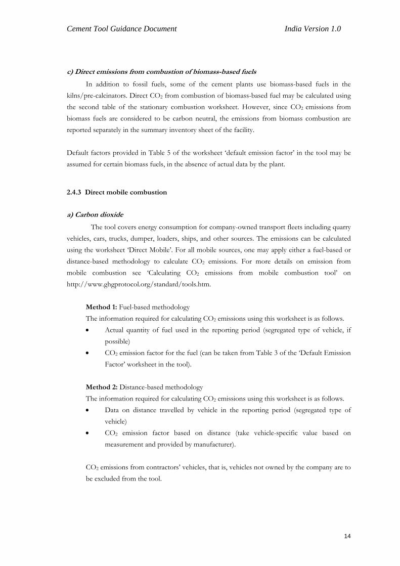
c) Direct emissions from combustion of biomass-based fuels
In addition to fossil fuels, some of the cement plants use biomass-based fuels in the kilns/pre-calcinators. Direct CO2 from combustion of biomass-based fuel may be calculated using the second table of the stationary combustion worksheet. However, since CO2 emissions from biomass fuels are considered to be carbon neutral, the emissions from biomass combustion are reported separately in the summary inventory sheet of the facility. Default factors provided in Table 5 of the worksheet ‘default emission factor’ in the tool may be assumed for certain biomass fuels, in the absence of actual data by the plant.
2.4.3 Direct mobile combustion
a) Carbon dioxide
The tool covers energy consumption for company-owned transport fleets including quarry vehicles, cars, trucks, dumper, loaders, ships, and other sources. The emissions can be calculated using the worksheet ‘Direct Mobile’. For all mobile sources, one may apply either a fuel-based or distance-based methodology to calculate CO2 emissions. For more details on emission from mobile combustion see ‘Calculating CO2 emissions from mobile combustion tool’ on http://www.ghgprotocol.org/standard/tools.htm.
Method 1: Fuel-based methodology The information required for calculating CO2 emissions using this worksheet is as follows. • Actual quantity of fuel used in the reporting period (segregated type of vehicle, if
possible) • CO2 emission factor for the fuel (can be taken from Table 3 of the ‘Default Emission
Factor’ worksheet in the tool). Method 2: Distance-based methodology The information required for calculating CO2 emissions using this worksheet is as follows. • Data on distance travelled by vehicle in the reporting period (segregated type of
vehicle) • CO2 emission factor based on distance (take vehicle-specific value based on
measurement and provided by manufacturer). CO2 emissions from contractors’ vehicles, that is, vehicles not owned by the company are to be excluded from the tool.
14
Cement Tool Guidance Document India Version 1.0
b) Sulphur dioxide
Emissions of SO2 from mobile sources can vary widely depending on the characteristics of the fuel, combustion conditions, and the presence of any control technologies. Available emissions factors are incomplete, and have large margins of error. In this version of the tool, only Method 1 — (fuel-based methodology) is provided for SO2 calculation from mobile sources, since the contribution of this source to the total corporate inventory is expected to be extremely low.
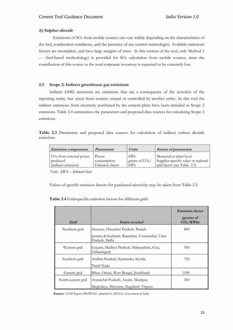
2.5 Scope 2: Indirect greenhouse gas emissions
Indirect GHG emissions are emissions that are a consequence of the activities of the reporting entity, but occur from sources owned or controlled by another entity. In this tool the indirect emissions from electricity purchased by the cement plant have been included as Scope 2 emissions. Table 2.4 summarizes the parameters and proposed data sources for calculating Scope 2 emissions.
Table 2.3 Parameters and proposed data sources for calculation of indirect carbon dioxide emissions
Emission components Parameters Units Source of parameters
CO2 from external power produced (indirect emission)
Power consumption Emission factor
kWh grams of CO2/ kWh
Measured at plant level Supplier-specific value or regional grid factor (see Table 2.5)
Note: kWh – kilowatt hour Values of specific emission factors for purchased electricity may be taken from Table 2.5.
Table 2.4 Grid-specific emission factors for different grids
Grid States covered
Emission factor
(grams of CO2/KWh)
Northern grid Haryana, Himachal Pradesh, Punjab
Jammu & Kashmir, Rajasthan, Uttaranchal, Uttar Pradesh, Delhi
800
Western grid Gujarat, Madhya Pradesh, Maharashtra, Goa, Chhattisgarh
930
Southern grid Andhra Pradesh, Karnataka, Kerala,
Tamil Nadu
750
Eastern grid Bihar, Orissa, West Bengal, Jharkhand 1190
North-eastern grid Arunachal Pradesh, Assam, Manipur,
Meghalaya, Mizoram, Nagaland, Tripura
360
Source: TERI Report 2002RT64, submitted to MNES, Government of India
15
Cement Tool Guidance Document India Version 1.0
2.6 Scope 3: Indirect carbon dioxide emissions due to clinker imported by the plant
Although Scope 3 can involve a large number of operations where the company has the capacity to influence (for details see GHG Inventory Protocol, www.ghgprotocol.org), in this tool, only indirect CO2 emissions due to clinker imported by the plant have been included. A default emission factor of 806 kg CO2 per tonne of clinker imported can be used. This is based on the average quality of limestone and coal used by the Indian cement industry. The emissions can be calculated using the worksheet ‘Indirect Clinker imports’ and the information required for calculating the emissions is only the actual clinker imported during the reporting period and the emission factor. If the actual emission factor from the plant from where the clinker has been imported is available, the same can be used. In case this information is not available, the default factor given above can be used.
2.7 Equity and control issues in corporate-level GHG reporting
For corporate reporting, two distinct approaches can be used to consolidate GHG emissions: the equity share approach and the control approach. Companies shall account for and report their consolidated GHG data according to either the equity share or control approach. If the reporting company wholly owns all its operations, its organizational boundary will be the same irrespective of the approach used. For companies with joint operations, the organizational boundary and the resulting emissions may differ depending on the approach used.
2.7.1 Equity share approach
Under the equity share approach, a company accounts for GHG emissions from operations according to its share of equity in the operation. The staff preparing the inventory may therefore need to consult the company’s accounting or legal staff to ensure that the appropriate equity share percentage is applied for each joint operation.
2.7.2 Control approach
Under the control approach, a company accounts for 100% of the GHG emissions from operations over which it has control. It does not account for GHG emissions from operations in which it owns an interest but has no control. Control can be defined in either financial or operational terms. When using the control approach to consolidate GHG emissions, companies shall choose between either the operational control or financial control criteria.
For further details on the equity and control approach, please refer to the publication GHG Protocol of Corporate Accounting and Reporting Standard.
16
Cement Tool Guidance Document India Version 1.0
3 Customized cement tool instructions
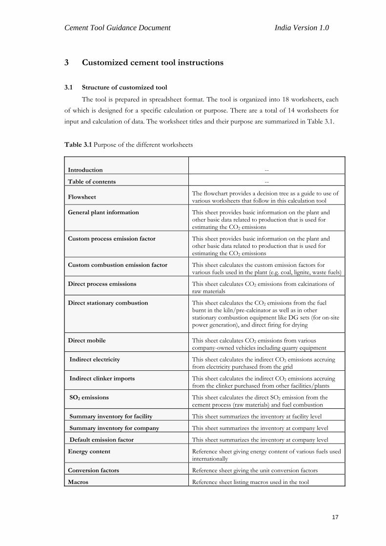
3.1 Structure of customized tool
The tool is prepared in spreadsheet format. The tool is organized into 18 worksheets, each of which is designed for a specific calculation or purpose. There are a total of 14 worksheets for input and calculation of data. The worksheet titles and their purpose are summarized in Table 3.1.
Table 3.1 Purpose of the different worksheets
Introduction --
Table of contents --
Flowsheet The flowchart provides a decision tree as a guide to use of various worksheets that follow in this calculation tool
General plant information This sheet provides basic information on the plant and other basic data related to production that is used for estimating the CO2 emissions
Custom process emission factor This sheet provides basic information on the plant and other basic data related to production that is used for estimating the CO2 emissions
Custom combustion emission factor This sheet calculates the custom emission factors for various fuels used in the plant (e.g. coal, lignite, waste fuels)
Direct process emissions This sheet calculates CO2 emissions from calcinations of raw materials
Direct stationary combustion
This sheet calculates the CO2 emissions from the fuel burnt in the kiln/pre-calcinator as well as in other stationary combustion equipment like DG sets (for on-site power generation), and direct firing for drying
Direct mobile This sheet calculates CO2 emissions from various company-owned vehicles including quarry equipment
Indirect electricity This sheet calculates the indirect CO2 emissions accruing from electricity purchased from the grid
Indirect clinker imports This sheet calculates the indirect CO2 emissions accruing from the clinker purchased from other facilities/plants
SO2 emissions This sheet calculates the direct SO2 emission from the cement process (raw materials) and fuel combustion
Summary inventory for facility This sheet summarizes the inventory at facility level
Summary inventory for company This sheet summarizes the inventory at company level
Default emission factor This sheet summarizes the inventory at company level
Energy content Reference sheet giving energy content of various fuels used internationally
Conversion factors Reference sheet giving the unit conversion factors
Macros Reference sheet listing macros used in the tool
17
Cement Tool Guidance Document India Version 1.0
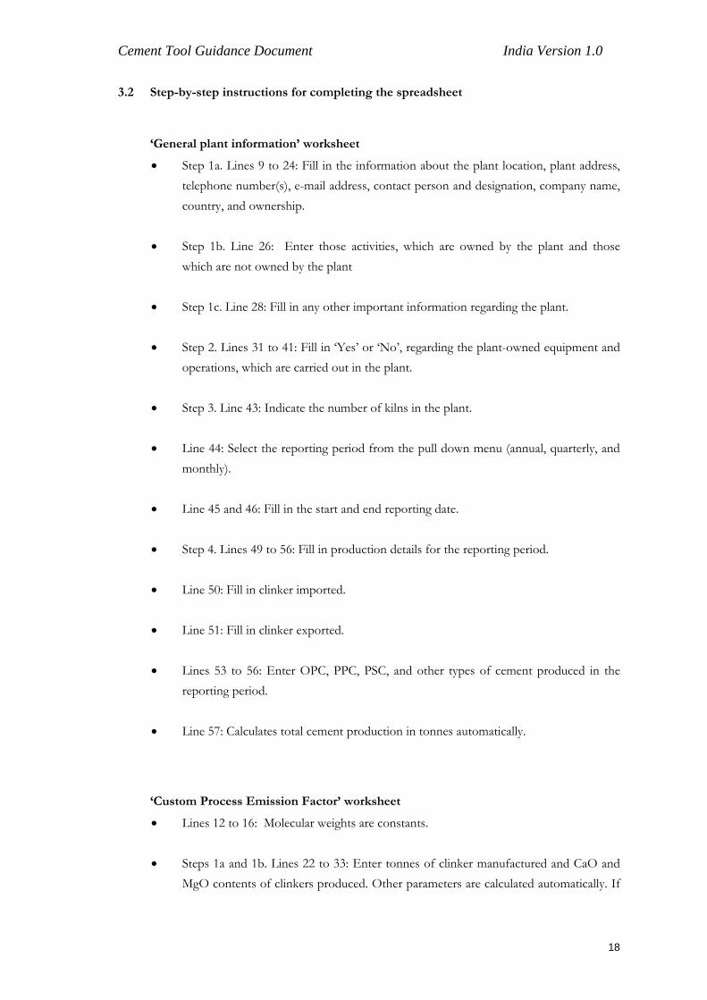
3.2 Step-by-step instructions for completing the spreadsheet
‘General plant information’ worksheet
• Step 1a. Lines 9 to 24: Fill in the information about the plant location, plant address, telephone number(s), e-mail address, contact person and designation, company name, country, and ownership.
• Step 1b. Line 26: Enter those activities, which are owned by the plant and those
which are not owned by the plant
• Step 1c. Line 28: Fill in any other important information regarding the plant.
• Step 2. Lines 31 to 41: Fill in ‘Yes’ or ‘No’, regarding the plant-owned equipment and operations, which are carried out in the plant.
• Step 3. Line 43: Indicate the number of kilns in the plant.
• Line 44: Select the reporting period from the pull down menu (annual, quarterly, and
monthly).
• Line 45 and 46: Fill in the start and end reporting date.
• Step 4. Lines 49 to 56: Fill in production details for the reporting period.
• Line 50: Fill in clinker imported.
• Line 51: Fill in clinker exported.
• Lines 53 to 56: Enter OPC, PPC, PSC, and other types of cement produced in the reporting period.
• Line 57: Calculates total cement production in tonnes automatically.
‘Custom Process Emission Factor’ worksheet
• Lines 12 to 16: Molecular weights are constants.
• Steps 1a and 1b. Lines 22 to 33: Enter tonnes of clinker manufactured and CaO and MgO contents of clinkers produced. Other parameters are calculated automatically. If
18
Cement Tool Guidance Document India Version 1.0
additional lines for clinker # 3 – n are added, formulas in lines 38 to 42 need to be adjusted manually (you will have to unprotect: follow the Excel commands).
• Step 1c. Lines 38 to 42: Calculates total clinker manufactured and average CaO and
MgO contents of clinkers produced automatically.
• Steps 2a and 2b. Lines 47 to 58: Enter tonnes of raw material and CaO and MgO contents of different raw materials consumed. Other parameters are calculated automatically. If additional lines for raw materials # 3 – n are added, formulae in lines 62 to 67 need to be adjusted manually (you will have to unprotect: follow the Excel commands).
• Step 2c. Lines 63 to 67 Calculates total raw material and average CaO, and MgO
contents of raw material automatically.
• Step 3. Lines 72 to 86: Most of the parameters are calculated automatically. Enter the degree of calcination in line 82 or use a default value if plant-specific values are not known.
• Step 3a. Line 92: Enter value for dust emission norms specified for your plant
(150 milligram/Nm3) or actual average dust emission as measured (in mg/Nm3).
• Step 3b. Line 93: Enter the average clinker production factor for your plant (Nm3/kg clinker). In case this figure is not available, use a default value of 1.5 Nm3 of flue gases/kg of clinker.
• Step 3c. Line 95: Calculate dust emissions per kilogram of clinker produced (mg dust
released/kg clinker).
• Step 3d: Line 96: Calculate dust emissions (tonnes of dust ).
‘Custom Combustion Emission Factor’ Worksheet
• Lines 19 to 23: Enter the names of fuels used in the plant (in the fuel type column). Additional rows may be inserted for different types of fuels used (including different types of coal used in the plant).
Step 1. Column A: Enter the average net calorific value of the fuel in GJ/metric tonne. Step 2. Column B: Enter the average carbon content of the fuel as a fraction.
19
Cement Tool Guidance Document India Version 1.0
Step 3. Column C: The emission factor for the fuel in kg CO2/GJ is calculated automatically.
‘Direct Process Emissions’ Worksheet
• Lines 18 to 19: Indicate ‘Yes’ or ‘No’ regarding use of the clinker-based methodology. If you enter ‘Yes’, ‘No’ will automatically be entered for the cement-based methodology question on line 19. If you enter ‘No’, ‘Yes’ will automatically be entered for the cement-based methodology question on line 19.
• Line 22 OR Line 41: Click on the button with the arrow next to the methodology which you will be using. This will reveal the rows for data entry for that methodology only.
• Line 30 (Clinker-based methodology) Step 1. Column A: Value is taken automatically from the sheet ‘Custom Process Emission Factor’. Step 2. Column B: The CO2 emission factor for clinker (in kg /tonne clinker produced) as calculated in the worksheet ‘Custom Process Emission Factor’. It automatically takes value as calculated in the sheet ‘Custom Process Emission Factor’. You can replace it with the default values of kg CO2 /tonne of clinker as given in the table in the worksheet ‘Default Emission Factor’ (based upon the location of the plant) only in case the plant-specific figures are not available. Step 3. Column C: The annual CKD lost (tonnes/year), as calculated in the worksheet ‘Custom process emission factor’ is used here. Step 4. Column D: The CO2 emission factor for CKD (in kg CO2/tonne of CKD lost) as calculated in the worksheet ‘Custom Process Emission Factor’ is used here. Use default values as given in the table of the worksheet ‘Default Emission Factor’ in case customized emission factors are not used. Step 5. Column E: Total CO2 emission in tonnes is calculated automatically
• Lines 50–64 (cement-based methodology)
Step 1. Column A: The value for cement production (tonnes) is automatically inserted from the worksheet ‘General plant information’. Step 2. Column B: Enter the clinker to cement ratio; if data is not available, use the default value, as given in tool.
20
Cement Tool Guidance Document India Version 1.0
Step 3. Column C: Automatically calculates clinker used for cement production (tonnes). Step 4. Column D: Automatically calculates total clinker used for cement production (tonnes). Step 5 and 6. Columns E and F: Automatically takes value of imported and exported clinker from the worksheet ‘General plant information’. Step 7. Column G: Automatically calculates total clinker produced in the facility. Step 8 and 9. Columns H and I: Enter tonne of raw material per tonne of clinker ratio and CaCO3 equivalent raw material ratio. Step 10. Column J: Put value of CO2 to CaCO3 stoichiometric ratio of 0.44. Step 11. Column K: Automatically calculates CO2 emissions factor (tonne CO2/tonne clinker produced). Step 12. Column L: Automatically calculates CO2 emissions (tonnes of CO2).
‘Direct Stationary Combustion’ Worksheet
• Lines 19–26 Enter source description and fossil fuel type, modify as required. Step 1. Column A: Enter the quantity of fuel burned. Step 2. Column B: Enter unit used to measure quantity of fuel. Step 3. Column C: Enter average net calorific value of fuel. Step 4. Column D: Enter unit of net calorific value in GJ/metric tonne (for solids) or GJ per litre (for liquids). Step 5. Column E: Automatically calculates quantity of fuel used in energy by multiplying the quantity of fuel burned by the average net calorific value of the fuel. Step 6. Column F: Enter unit of quantity of fuel used in energy. Verify that the units for columns B through F are consistent.
21

Cement Tool Guidance Document India Version 1.0
Step 7. Column G: Enter CO2 combustion emission factor. Take either the emission factors calculated in the worksheet ‘Custom combustion factor’ or take default values given in Tables 2, 3, and 5 of the ‘Reference worksheet’. Step 8. Column H: Enter unit of CO2 emission factor. Step 9. Column I: Enter oxidized carbon fraction. Step 10. Columns J and K: Automatically calculates CO2 emission in kilograms and tonnes. If something other than kg CO2/GJ was used in column H, verify that the units are consistent. Step 11. Line 28: Calculates automatically sum of CO2 emissions for fossil fuel combustion.
• Lines 46–53
Same procedure as followed for fossil fuels. Line 55 automatically calculates total biomass-based fuel CO2 emissions.
‘Direct mobile’ Worksheet
• Lines 18 to 19: Enter ‘Yes’ or ‘No’ for whether the fuel consumption-based method will be used. If you enter ‘Yes’, ‘No’ will automatically be entered in Line 19 for the distance-based method. If you enter ‘No’, ‘Yes’ will automatically be entered in Line 19 for the distance-based method.
• Line 22 or Line 47: Select the button with the arrow next to the method that you will be using to calculate direct mobile emissions. Only the cells and rows for that method will be revealed.
• Lines 31 to 37 (Fuel-based method) Enter the source and type of fuel in different mobile applications. Make similar entry for cars, dumpers, buses, shipping, and other mobile sources used in the plant location. Step 1. Column A: Enter annual quantity of fuel consumed. Step 2. Column B: Enter the unit used to measure quantity of fuel used. Step 3. Column C: Enter CO2 emission factor
22
Cement Tool Guidance Document India Version 1.0
Step 4. Column D: Enter unit of CO2 emission factor. Calculate/derive CO2 emission factor using the emission factors provided in the Worksheet ‘Default Emission Factor’. Verify that the units used in columns B and D are consistent. Step 5. Column E: Enter oxidized carbon fraction, if oxidation carbon faction is not known use default as 0.99. Step 6. Columns F and G: Parameters are calculated automatically. Step 7. Line 39: Parameter is calculated automatically.
• Line 57-64 (Distance-based method)
Step 1. Column A: Enter distance (in km) travelled by vehicle. Step 2. Column B: Enter CO2 emission factor (kg CO2/km), it varies with vehicle type, load on the vehicle, and road condition. Step 3. Column C: Parameter is calculated automatically. Step 4. Line 66: Parameter is calculated automatically.
‘Indirect electricity’ Worksheet
• Lines 18 to 27
Enter the source or grid from which electricity is imported in the first column Step 1. Column A: Enter annual electricity purchased in kilowatt hour Step 2. Column B: Insert CO2 emission factor for purchased electricity. Default values are provided in the worksheet, ‘Default emission factor’, based upon the location of the plant. Step 3. Column C: Parameter is calculated automatically. Step 4. Line 29: Parameter is calculated automatically.
‘Indirect-clinker imports’ Worksheet
• Line 16
23
Cement Tool Guidance Document India Version 1.0
Step 1. Column A: Data are taken automatically from ‘General plant information’ worksheet. Step 2. Column B: Default values may be used. Step 3. Column C: Parameter is calculated automatically.
‘SO2 emissions’ Worksheet
• Line 20
Step 1a. Column A: Data are taken automatically from 'General plant information' worksheet. Step 1b. Column B: Enter SO2 emission factor for cement (kg SO2/tonne cement produced). If plant-specific data is not available leave it blank. Step 1c. Columns C and D: Parameter is calculated automatically by multiplying the cement production by the SO2 emission factor.
• Lines 37 to 46
Enter source description
Step 2a. Columns A and B: Enter fuel type and quantity of fuel burned Step 2b. Column C: Enter sulphur content of fuel. Use plant-specific data. If not available use default values given in the tool. Step 2c. Column D: Enter typical density values for liquid fuels. Use default values given in the tool if plant-specific data is not available. Step 2d. Columns E and F: Parameter is calculated automatically Step 2e. Line 48: Total SO2 emissions from stationary fuel combustion are calculated automatically.
24

Cement Tool Guidance Document India Version 1.0
• Lines 60–66
Step 3a. Columns A–C: For the first three columns, that is, fossil fuel type, quantity of fuel burnt, and unit used to measure quantity of fuel, enter the relevant information. Step 3b. Column D: Enter sulphur content by percent weight; use default values given in the tool if plant-specific data is not available. Step 3c. Column E: Enter typical density. Use default values given in the tool if plant-specific data is not available. Step 3d. Columns F and G: Parameters are calculated automatically. Step 3e. Row 68: Sum SO2 emissions from mobile sources is automatically generated. Step 4. Row 79: Total direct SO2 emissions from stationary and mobile sources calculated automatically if Steps 1a-c, 2a-e, and 3a-e are completed.
‘Summary inventory for facility’ worksheet
• Lines 9, 10, 12, 13, and 14: Taken automatically from ‘General plant information’ worksheet
• Line 17: Taken automatically from ‘Direct process emissions’ worksheet.
• Line 18: Taken automatically from ‘Direct stationary combustion’ worksheet.
• Line 19: Taken automatically from ‘Direct mobile’ worksheet.
• Line 20: Sums the direct emissions data automatically.
• Line 23: Taken automatically from ‘Indirect-electricity’ worksheet.
• Line 25: Taken automatically from ‘Indirect-clinker imports’ worksheet.
• Line 28: Taken automatically from ‘Direct stationary combustion’ worksheet.
• Line 29: Taken automatically from ‘SO2 emissions’ worksheet.
25
Cement Tool Guidance Document India Version 1.0
‘Summary inventory for company’ worksheet
• Lines 14 to 18 Enter data as indicated in tool (company, organizational boundaries chosen, etc.). • Line 27 Step 1. Column A: Enter facility name.
Step 2. Column B: Enter control percentage (0 or 100) in the facility. Step 3. Column C: Enter equity share percentage in the facility. Step 4. Column D: Enter production of cement from facility in tonnes from ‘General plant information’ worksheet. Step 5a. Column E: Enter direct process-related emissions (tonnes CO2). Step 5b. Column F: Enter direct emissions from stationary combustion (tonnes CO2). Step 5c. Column G: Enter direct emissions from mobile sources (tonnes CO2). Step 5d. Column H: Sums data from Columns E, F, and G automatically. Step 6. Column I: Enter indirect emission from purchased electricity (tonnes CO2). Step 7. Column J: Enter indirect emissions from imported clinker (tonnes CO2). Step 8. Columns K and L: Absolute CO2 per stage is automatically calculated.
• Line 28 to 39. Follow the same procedure as Line 27 but the formulae will have to be
inserted for columns H, K, and L if you insert additional rows.
• Step 9. Line 40: Sums data automatically
‘Default emission factor’, ‘Energy content,’ and ‘Conversion factors’ Worksheets
These worksheets are provided as reference, and for guiding the user while filling up the calculation worksheets. The sheets are self-explanatory.
26
Cement Tool Guidance Document India Version 1.0
4 Internal reporting and documentation
4.1 Data source
The cement plants in India normally maintain production records on a financial year basis, which is in a way mandatory. The plants also have verifiable documentation of purchases like coal and electricity. Most of the other data required for completing the worksheets can be obtained from the production records, log-sheets of different sections or departments, etc. Companies have the option to use defaults or customized values based on appropriate data on the type of fuel and raw material used. Companies should give preference to customized emission factors.
4.2 Monitoring and verification
The GHG inventory is a very useful tool for documentation of accurate historical GHG emissions by a company. However in order to be useful and verifiable, it is suggested that the company-specific data provided in the tool should be from a documented source or verifiable internal records. This would ensure usefulness of the tool for other purposes such as development of ‘carbon offset’ projects which will invariably require verification of carbon credits. 5 References
The customized tool and this guidance document have extensively used the information and guidance instructions given in the following documents.
1 The Greenhouse Gas Protocol: A corporate accounting and reporting standard 2 Calculating CO2 emissions from production of cement: clinker-based methodology
based upon IPCC guidelines –The WBCSD CO2 Protocol. 3 Climate Leaders Greenhouse Gas Inventory Protocol: cement sector guidelines 4 Calculating CO2 emissions from the production of cement: clinker-based
methodology based on USEPA Climatewise programme. 5. IPCC guidelines for national greenhouse gas inventories.
In addition, various sources have been used for the default values and these are mentioned in the tool.
27
Cement Tool Guidance Document India Version 1.0
6 Acknowledgements
TERI acknowledges that portions of the tool and the guidance document contain spreadsheets
and texts extracted from the WRI/WBSCD Cement Tool, the WRI/WBCSD GHG Inventory
Protocol, and Climate Leaders GHG Inventory Protocol for cement sector. TERI extends its due
acknowledgement for using these documents towards preparation of the customized tool and
guidance document for cement plants in India. TERI is also grateful to USEPA for supporting the
preparation of the tool and to the reviewers for providing comments for finalization of the tool. The
support provided by Gujarat Ambuja Cement Ltd for road testing of the tool at one of their plants is
deeply appreciated.
TERI also acknowledges the encouragement and back-up support received from Central Pollution
Control Board (CPCB) and other industry partners during the preparation of the calculation tool.
7 Contributors USEPA team
Ms. Katherine Sye Grover Ms. Mausami Desai WRI team
Mr. Pankaj Bhatia Mr. Anthony Dvarskas TERI team
Mr. Girish Sethi Mr. Prosanto Pal Mr. N Vasudevan Mr. Amit Gupta (till April 2005)
List of peer reviewers
Mr. K.S.Venkatagiri (Confederation of Indian Industry) Dr S P Ghosh (Cement Manufacturers’ Association) Dr K C Narang {Dalmia Cement (Bharat) Limited} Mr Kamal Kumar (Holtec Consulting Pvt Ltd) Ms Lisa Hanle (Environmental Protection Agency)
28

Cement Tool Guidance Document India Version 1.0
Ambuja Cement team (Road tester) Mr. Y K Saxena Mr. Atul Kumar Mr. B K Mishra (till March 2005) Other contributors
Dr B Sengupta (Central Pollution Control Board)
29
Cement Tool Guidance Document India Version 1.0
A. Appendix
Methodology for calculation of customized carbon dioxide emission factor for raw
materials calcination
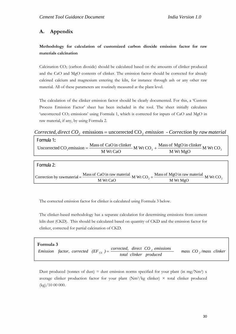
Calcination CO2 (carbon dioxide) should be calculated based on the amounts of clinker produced and the CaO and MgO contents of clinker. The emission factor should be corrected for already calcined calcium and magnesium entering the kiln, for instance through ash or any other raw material. All of these parameters are routinely measured at the plant level. The calculation of the clinker emission factor should be clearly documented. For this, a ‘Custom Process Emission Factor’ sheet has been included in the tool. The sheet initially calculates ‘uncorrected CO2 emissions’ using Formula 1, which is corrected for inputs of CaO and MgO in raw material, if any, by using Formula 2.
material rawbyCorrection- emissionCOdirectCorrected, 2 2COduncorrecteemissions =Formula 1: 222 CO Wt M
MgO Wt Mclinkerin MgO of MassCO Wt M
CaO Wt Mclinker in CaO of MassemissionCO dUncorrecte +=
Formula 2:
22 CO Wt MMgO Wt M
material rawin MgO of MassCO Wt MCaO Wt M
material rawin CaO of MasslrawmateriabyCorrection +=
The corrected emission factor for clinker is calculated using Formula 3 below. The clinker-based methodology has a separate calculation for determining emissions from cement kiln dust (CKD). This should be calculated based on quantity of CKD and the emission factor for clinker, corrected for partial calcination of CKD.
Formula 3
clinker /massCO mass produced clinker total
emissions CO direct corrected, )(EF corrected factor, Emission 2
2Cli =
Dust produced (tonnes of dust) = dust emission norms specified for your plant (in mg/Nm3) x average clinker production factor for your plant (Nm3/kg clinker) × total clinker produced (kg)/10 00 000.
30
Cement Tool Guidance Document India Version 1.0
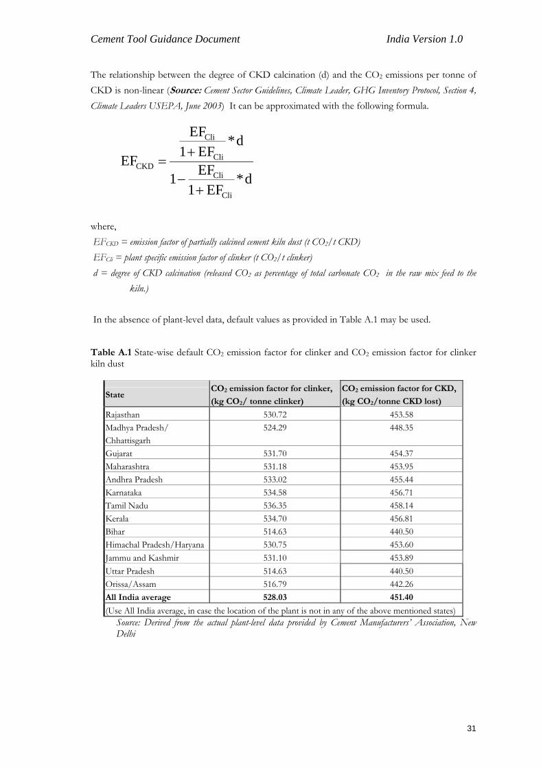
The relationship between the degree of CKD calcination (d) and the CO2 emissions per tonne of CKD is non-linear (Source: Cement Sector Guidelines, Climate Leader, GHG Inventory Protocol, Section 4, Climate Leaders USEPA, June 2003) It can be approximated with the following formula.
d*EF1
EF1
d*EF1
EF
EF
Cli
Cli
Cli
Cli
CKD
+−
+=
where, EFCKD = emission factor of partially calcined cement kiln dust (t CO2/t CKD) EFCli = plant specific emission factor of clinker (t CO2/t clinker) d = degree of CKD calcination (released CO2 as percentage of total carbonate CO2 in the raw mix feed to the
kiln.) In the absence of plant-level data, default values as provided in Table A.1 may be used. Table A.1 State-wise default CO2 emission factor for clinker and CO2 emission factor for clinker kiln dust
State CO2 emission factor for clinker,
(kg CO2/ tonne clinker)
CO2 emission factor for CKD,
(kg CO2/tonne CKD lost)
Rajasthan 530.72 453.58 Madhya Pradesh/ Chhattisgarh
524.29 448.35
Gujarat 531.70 454.37 Maharashtra 531.18 453.95 Andhra Pradesh 533.02 455.44 Karnataka 534.58 456.71 Tamil Nadu 536.35 458.14 Kerala 534.70 456.81 Bihar 514.63 440.50 Himachal Pradesh/Haryana 530.75 453.60 Jammu and Kashmir 531.10 453.89 Uttar Pradesh 514.63 440.50 Orissa/Assam 516.79 442.26 All India average 528.03 451.40
(Use All India average, in case the location of the plant is not in any of the above mentioned states) Source: Derived from the actual plant-level data provided by Cement Manufacturers’ Association, New Delhi
31