index section 4 - · pdf fileindex section 4 power take offs ... the choice of transmission...
TRANSCRIPT

POWER TAKE-OFFS 4-1TRAKKER Euro 4/5
Print 603.93.731 Base - July 2007
Index
Index
SECTION 4
Power take offs
Page
4.1 General Specifications 4-3
4.2 Power Take-off from Gearbox 4-5
4.3 Power Take-off from Transfer Box 4-8
4.4 Power Take-off from Drive line 4-9
4.5 Power Take-off from Engine 4-10
4.5.1 Torque power take off from the front of the engine 4-10
4.5.2 Power take off from the rear of the engine 4-11
4.6 PTO management 4-17
4.6.1 General Specifications 4-18
4.6.2 PTO 0 mode (run mode) 4-18
4.6.3 Configurable PTO 1, 2, 3 modes 4-19
4.6.3.1 Changing the torque curve, maximum rpm and the overrun regulator curve gradient 4-21
4.6.4 Intermediate rpm regulator 4-23
4.6.5 Standard configurations 4-24
4.6.6 Specific indications: correlation between the VCM configuration and the installed power take offs 4-25
4.6.7 Engaging the power take off 4-25
4.6.8 With Allison Gearbox 4-25
4.6.9 Use of the power take-off with vehicle in motion 4-25
4.7 EM (Expansion Module) 4-28
4.7.1 Connections 4-29
4.7.2 PTO activation/deactivation conditions: 4-30
4.7.3 No PTO installed or provisions for PTO: 4-30
4.7.4 PTO Multipower 4-30
4.7.5 PTO manual gearbox with electric engagement 4-31
4.7.6 PTO FOCSA 4-32

4-2 POWER TAKE-OFFS TRAKKER Euro 4/5
Base - July 2007 Print 603.93.731
Index
Page
4.7.7 Engine PTO 4-32
4.7.8 PTO Eurotronic 2 transmission 4-33
4.7.9 PTO TRANSFER BOX 4-33
POWER TAKE-OFFS 4-3TRAKKER Euro 4/5
Print 603.93.731 Base - July 2007
General Specifications
4444.4
General Specifications
4.1 General Specifications
Different types of power takeoffs can be used dependine on the type of use and the performances required, the the PTO canbe fitted to:
- The gearbox.
- Driveline.
- The front of the engine.
- The rear of the engine.
The characteristics and performances are given in the paragraphs which follow and in the relevant documentation which will besupplied upon request.
For the definition of the power necessary for the apparatus to be controlled, particularly when the values requested are high, theabsorbed power should also be considered during the drive transmission phase (5 to 10% for the mechanical transmissions, beltsand gears, and greater values for the hydraulic controls).
The choice of transmission ratio for the power take-off should be made so that the absorption of power occurs in a flexible engineoperating range. Low r.p.m. (below 1,000 r .p.m.) must be avoided to prevent irregular running .
The power taken in relation to the number of revolutions of the power take-off at the required torque.
P(CV)= M ⋅ n7023
P(kW)= M ⋅ n9550
P = Useable powerM = Torque permitted for the power take-off (Nm)n = power take-off r.p.m.
Type of use
Both occasional and continuous use should be considered.
For occasional use periods of under 30 minutes are considered.
The values for continuous use are those used for long periods.Whenever this is comparable to that of a stationary engine, the suitabil-ity of reducing the scheduled values on the basis of the conditions of use (engine cooling, gearbox etc.) should be evaluated.
The scheduled take-off values are also applicable for uses which do not involve large variations of torque either in frequency ormagnitude.
To avoid overloading, in some cases (e.g. hydraulic pumps, compressors) it may be necessary to include the application of deviceslike clutches or safety valves.
PTO transmissions
The kinematic forces of the transmission from the power take-off to the relevant apparatus should be carefully considered (angles,r.p.m., moment) during the design phase and the dynamic behaviour during operation in compliance with the transmission Manufac-turer’s instructions should be respected. The dimensions should take into consideration the forces which might occur under maxi-mum power and torque conditions.
To obtain a uniformity of kinetic forces angles of equal value, maximum of 7º, should be obtained at the extremities (Figure 4.1). Solution Z is preferred to solutionWdue to the lower loads on the bearings of the power take-off and the equipment being driven.When it is necessary to obtain different spatial inclinations (ϕ), the variations in r.p.m. should be compensated for with the arrange-ment of the forks shown in Figure 4.2.
For transmissions employing multiple sections, the instructions given at point 2.8.2 should be followed.

4-4 POWER TAKE-OFFS TRAKKER Euro 4/5
Base - July 2007 Print 603.93.731
General Specifications
Solution Z
Solution W
91522
Figure 4.1
Figure 4.2
91523
Transmission PTO data
The following table specifies the types of P.T.O. envisaged by ZF and by Hydrocar.
The transmission P.T.O. and the Body Computer (BC) will need to be reprogrammedwhen a PTO is applied after-market. Interven-tions on the electrical and pneumatic system are required. Read paragraph 4.6 ”PTO management” carefully before applying a PTO.
Re-programming of the electronic control units must be carried out in accordance with the instructions in the IVECO technicalmanual using exclusively the diagnostic instrument (available from IVECO dealers and authorised IVECO service centres), furnishingthe information concerning the specific P.T.O. utilized.
Electrical system
The MUX system enables innovative management of the P.T.O.s with benefits in terms of safety and reliability, by means of theconnection of the P.T.O. control switches to connector ST14.
Said connection is already present when the customer orders the optional P.T.O. If the P.T.O. is fitted after the vehicle is purchasedfollow the prescriptions given in heading 4.6
Pneumatic system
For air intake, see instructions at para 2.15.4.

POWER TAKE-OFFS 4-5TRAKKER Euro 4/5
Print 603.93.731 Base - July 2007
Power Take-off from Gearbox
Power Take---off from Gearbox
4.2 Power Take-off from Gearbox
Depending on the type of gearbox power can be taken from the layshaft through the flange or spline located on the rear, sideor lower part of the gearbox.
The technical characteristics necessary are given in the documentation supplied upon request for the various gearboxes.
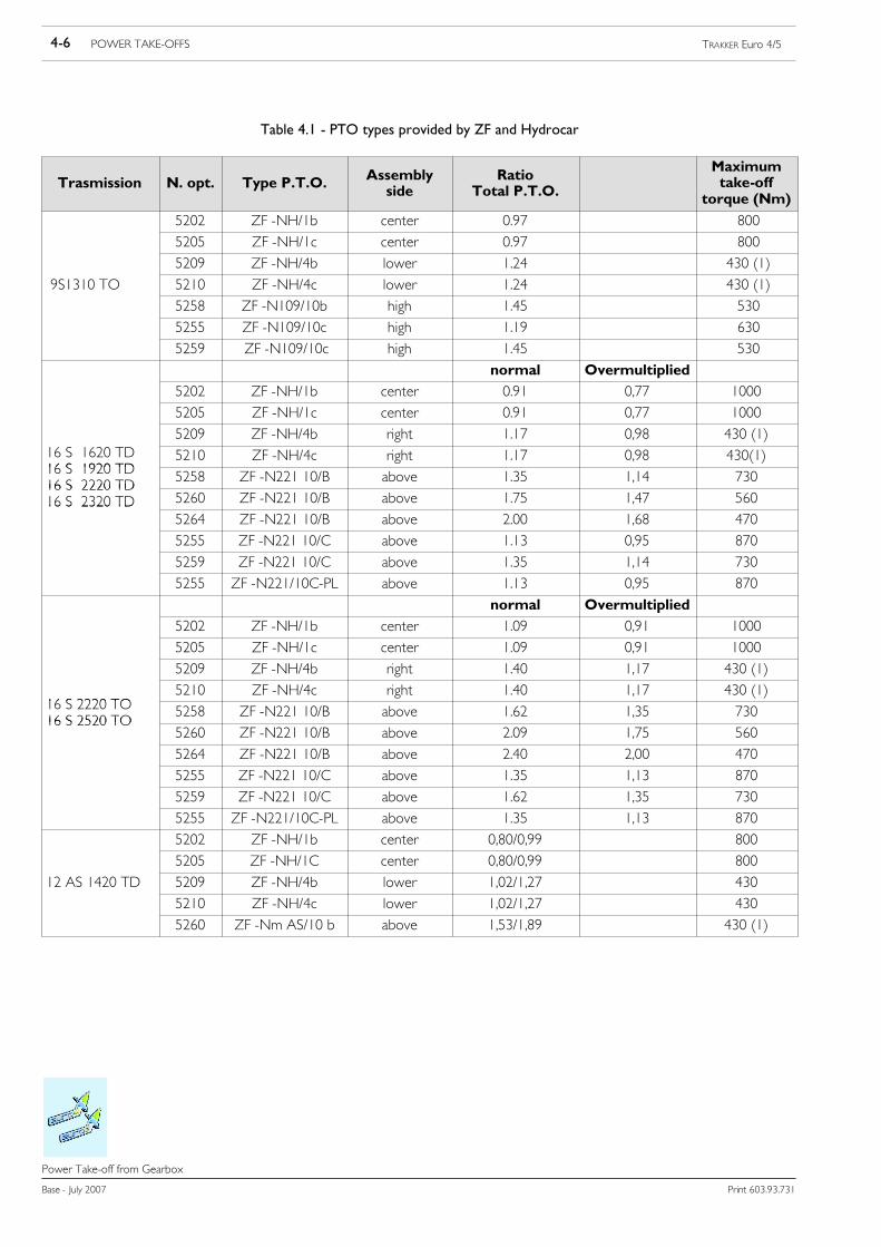
The types of power take-off and the torque values obtained with the ratio between the number of output revolutions and enginer.p.m. are shown in Table 4.1.
The values refer to the conditions indicated in the table.
Higher values for occasional use must be agreed upon as each occasion arises depending on the type of use.
Check the vehicle to ascertain whether it is possible to fit a power take-off suitable to its size.
The power take-off applied to the gearbox must only be used when the vehicle is stationary and must be engaged and disengagedwhen the clutch is disengaged to avoid excessive stress on the synchronisers during gear change. For special situations when thepower take-off is used and the vehicle is moving the gear must not be changed.
For gearboxes equipped with a torque converter, the same power take- offs used for normal gearboxes are, as a rule, used. It shouldbe carefully noted that, when the engine r.p.m. is below 60% of the max. value the converter will be in the phase of hydraulic r.p.m.;in this phase, depending on the absorbed power, the r.p.m. of the power take-off is subject to oscillation despite the fact that theengine r.p.m. is constant.
Direct Application of Pumps
When the application of pumps of other equipment (e.g. for tippers or cranes) is carried out directly from the power take-off,without the use of intermediate shafts and after checking that the size of the pump permits margins of safety with chassis and engineunit (cross member, transmission shaft etc.), the static and dynamic torques exerted by the mass of the pump and by the powertake-off should be checked for compatibility with the resistance of the walls of the gearbox. By way of an example, the momentdue to the additional masses must not have values of over 3% approx. of the maximum engine torque.
In cases where the gearbox is applied in a single unit with the engine, the value of the additional masses must be verified with regardto the inertial effects in order to avoid the induction of resonance conditions in the engine unit within the field of operational enginer.p.m.
!When fitting power take-offs the torque values shown in Table 4.1 must not be exceeded.
Transmission oil temperature must not exceed 120°C during prolonged use. Coolant temperaturemust not exceed100°C.Not all types of power take-off available on themarket are suitable for continu-ous use. When in use the specifications (working periods, pauses etc.) specific to the power take-offin question should be respected.
4-6 POWER TAKE-OFFS TRAKKER Euro 4/5
Base - July 2007 Print 603.93.731
Power Take-off from Gearbox
Table 4.1 - PTO types provided by ZF and Hydrocar
Trasmission N. opt. Type P.T.O.Assemblyside
RatioTotal P.T.O.
Maximumtake-off
torque (Nm)
5202 ZF -NH/1b center 0.97 800
5205 ZF -NH/1c center 0.97 800
5209 ZF -NH/4b lower 1.24 430 (1)
9S1310 TO 5210 ZF -NH/4c lower 1.24 430 (1)
5258 ZF -N109/10b high 1.45 530
5255 ZF -N109/10c high 1.19 630
5259 ZF -N109/10c high 1.45 530
normal Overmultiplied
5202 ZF -NH/1b center 0.91 0,77 1000
5205 ZF -NH/1c center 0.91 0,77 1000
5209 ZF -NH/4b right 1.17 0,98 430 (1)16 S 1620 TD16 S 1920 TD
5210 ZF -NH/4c right 1.17 0,98 430(1)16 S 1920 TD16 S 2220 TD
5258 ZF -N221 10/B above 1.35 1,14 73016 S 2220 TD16 S 2320 TD 5260 ZF -N221 10/B above 1.75 1,47 56016 S 2320 TD
5264 ZF -N221 10/B above 2.00 1,68 470
5255 ZF -N221 10/C above 1.13 0,95 870
5259 ZF -N221 10/C above 1.35 1,14 730
5255 ZF -N221/10C-PL above 1.13 0,95 870
normal Overmultiplied
5202 ZF -NH/1b center 1.09 0,91 1000
5205 ZF -NH/1c center 1.09 0,91 1000
5209 ZF -NH/4b right 1.40 1,17 430 (1)
16 S 2220 TO5210 ZF -NH/4c right 1.40 1,17 430 (1)
16 S 2220 TO16 S 2520 TO
5258 ZF -N221 10/B above 1.62 1,35 73016 S 2520 TO
5260 ZF -N221 10/B above 2.09 1,75 560
5264 ZF -N221 10/B above 2.40 2,00 470
5255 ZF -N221 10/C above 1.35 1,13 870
5259 ZF -N221 10/C above 1.62 1,35 730
5255 ZF -N221/10C-PL above 1.35 1,13 870
5202 ZF -NH/1b center 0,80/0,99 800
5205 ZF -NH/1C center 0,80/0,99 800
12 AS 1420 TD 5209 ZF -NH/4b lower 1,02/1,27 430
5210 ZF -NH/4c lower 1,02/1,27 430
5260 ZF -Nm AS/10 b above 1,53/1,89 430 (1)

POWER TAKE-OFFS 4-7TRAKKER Euro 4/5
Print 603.93.731 Base - July 2007
Power Take-off from Gearbox
Table 4.1 - (continued) PTO types provided by ZF and Hydrocar
Trasmission N. opt. Type P.T.O. Assembly sideRatio
Total P.T.O.
Maximumtake-offtorque(Nm)
5202 ZF -NH/1b center 0.82 1000
5209 ZF -NH/4b right 1.05 430 (1)
12 AS 1930 TD5210 ZF -NH/4c above /H 1.05 430 (1)
12 AS 1930 TD12 AS 2330 TD 5260
ZF N AS/10bflange
above /H 1.92 400
6420ZF -Nm AS/10b above/L/pump 1.21 670
6420ZF Nm AS/10bdouble output
above/L/pumplower/H/flange 1.92 400
5202 ZF -NH/1b center 1.35 1000
5209 ZF -NH/4b right 1.22 430 (1)
12 AS 2330 TD5210 ZF -NH/4c above /H 1.22 430 (1)
12 AS 2330 TD12 AS 2530 TD 5260
ZF N AS/10bflange
above /H 2.15 400
6420ZF -Nm AS/10b above/L/pump 1.23 670
6420ZF Nm AS/10bdouble output
above/L/pumplower/H/flange 1.73 400
1) Limit 1h

4-8 POWER TAKE-OFFS TRAKKER Euro 4/5
Base - July 2007 Print 603.93.731
Power Take-off from Transfer Box
Power Take---off from Transfer Box
4.3 Power Take-off from Transfer Box
In vehicles with all wheel drive (4x4) the application of power take- offs on the transfer box is possible. The r.p.m. for this usemay be chosen on the basis of the most suitable gear.
Use is permitted only when the vehicle is stationary (transfer box in neutral). The specification regarding the correct use are givenin the Owner’s Manual supplied with the vehicle.
The available take-off values are given below:
Table 4.2
Power take-off
Transfer box typeMax. torque (Nm)
Output typeTransfer box typeOutput
Output type
TC 1800 (1) 1180 Flange ∅ ext. dia. 120 mm 8 holes dia.TC 2200 (1) 1180
Flange ∅ ext. dia. 120 mm 8 holes dia.∅ 10 mm; or direct pumps coupling
(1) When the optional Power Take Off is required, detailed internal changes to the Transfer Box have to bemade, therefore contact Sales Engineering for furtherinformation.
For further information contact IVECO S.p.A., Technical Application,Strada delle Cascinette 424/34, 10156 Torino(E-mail: [email protected]).

POWER TAKE-OFFS 4-9TRAKKER Euro 4/5
Print 603.93.731 Base - July 2007
Power Take-off from Drive line
Power Take---off from Drive line
4.4 Power Take-off from Drive line
The authorisation for the application of a power take-off on the drive line downstream of the gearbox is issued after examinationof the complete documentation presented to the Company.
The various power and torque values will be evaluated as each occasion arises on the basis of the conditions of use.
In general the following should be noted:
- The drive take-off may be operated only when the vehicle is stationary.
- The power take-off r.p.m. is dependent on the gear selected.
- The power take-off must be located immediately downstream of the gearbox. For vehicles with the drive line in two or moresections, the power take-off may also be fitted at the flexible support included between the first and second sections (respectthe indications given in point 2.8.2).
- The angles of the drive line on the horizontal plane and vertical plane must be kept as close as possible to the original values.
- Masses and rigidity added to the drive line must not provoke a loss of balance or abnormal vibrations or damage the transmissiondrive line (from engine to axle) either during vehicle movement or during operation with the motor running.
- The power take-off must be fixed to the chassis with its own suspension.
As the transmission is an important part for the safety of the vehicle, modification to it must only becarried out by specialist companies approved by the supplier of the transmission.
NOTE

4-10 POWER TAKE-OFFS TRAKKER Euro 4/5
Base - July 2007 Print 603.93.731
Power Take-off from Engine
Power Take---off from Engine
4.5 Power Take-off from Engine
In general the use of these power take-offs is planned for apparatus requiring a continuous power supply.
4.5.1 Torque power take off from the front of the engine
The drive take-off from the front part of the crankshaft is obtained, for limited power values to be drawn off (e.g. air conditioningetc.) by drive belt transmission, the use of coupling shafts is normally reserved for take-offs of a greater magnitude (e.g. municipaluse).
These uses, when not specifically planned, require precise modifications to the front part of the vehicle, e.g. modifications to theradiator, cab, bumpers etc. Particular attention must therefore be paid:
- To the system comprising additional masses and relative rigidity which must be flexibly disengaged from the crankshaft with regardto the torsional and flexional effects.
- To the additional mass values and relative moments of inertia and to the distance from the centre of gravity of the masses from thecentreline of the first main bearing which must be kept to a minimum.
- To avoiding a reduction in the radiator cooling capacity and dead water areas.
- To restoring the rigidity and resistance characteristics of the modified elements (cross member, bumper etc.).
- To avoid exceeding, during extended use, temperatures of the engine cooling fluid of over 100°C and engine oil temperature (measu-red on the main duct of the pressure switch area) of 110 to 120°C. A margin of approx. 10% should however be left. In other casesinclude supplementary heat exchangers.
Table 4.3 shows the values to be referred to for the take-off.
Table 4.3 - Power take-off from front of engine
Max. rpm Max. take-off values
Engine type(power)
Rpm corresp.to full power
Max. rpmadmitted(start of red
band)
Max.torqueavailable
Max.moment ofinertia
Max.bendingmoment
Momentmultipl.factor
Multipl.factorang. pos.
(kW/Cv) rad/s (rpm) rad/s (rpm) (Nm) (kgm2)1) (Nm)2) (-)3) (degrees)4)
Serie Cursor 8 - F2B
E0681C (200/273) 251 2400 324 3100 400 0.050 120 2 180-210
E0681B (229/310) 251 2400 324 3100 400 0.050 120 3 210-240
E0681A (259/352) 251 2400 324 3100 400 0.050 120 4 240-300
3 300-330
2 330-360
Serie Cursor 13 - F3B
E0681G (279/380) 199 1900 262 2500 500 0.050 150 1 0-180
E0681C (324/440) 199 1900 262 2500 500 0.050 150 2 180-210
E0681E (353/480) 199 1900 262 2500 500 0.050 150 3 210-240
4 240-300
3 300-330
2 330-360
1) Maximum moment of inertia of rigidly added masses.2) Max. moment of flexure due to radial forces in relation to the first main support.3) Amplification factor of the max. permitted flexural moment (depending on the angular position of the additional radial forces)4) Direction of the additional radial forces. (zero: TDC cylinder axis; rotation: clockwise).

POWER TAKE-OFFS 4-11TRAKKER Euro 4/5
Print 603.93.731 Base - July 2007
Power Take-off from Engine
4.5.2 Power take off from the rear of the engine
a) Power takeoff from engine flywheel
On some models as an option, the IVECO Multipower power take-off is available. This is installed on the rear of the engine andis suitable for high power applications absorption when the vehicle is in gear and stationary (e.g. municipal vehicles, cement mixerse tc.)
The total PTO is equipped with a non synchronized clutch with pneumatic-mechanical actuation (external to the cabin) the engage-ment / disengagement must only be carried out when the engine is stationary.
Safety against engagement with engine running is ensured by conditioning PTO engagement request control to PTO engaged indica-tor light on instrument panel.
Engine starting must only occur with no load on the PTO.
The power take-off occurs through the engine flywheel and is separate from the clutch control. Themain dimensional characteristicsare given in Figure 4.3 while the technical characteristics are shown in Table 4.4.
Figure 4.3
91524180
Currently available is an option for a mechanical control with flanged output via coupling shaft. The engagement and disengagementmust be carried out when the engine is stationary. A safety device prevents its use when the engine is running.
4-12 POWER TAKE-OFFS TRAKKER Euro 4/5
Base - July 2007 Print 603.93.731
Power Take-off from Engine
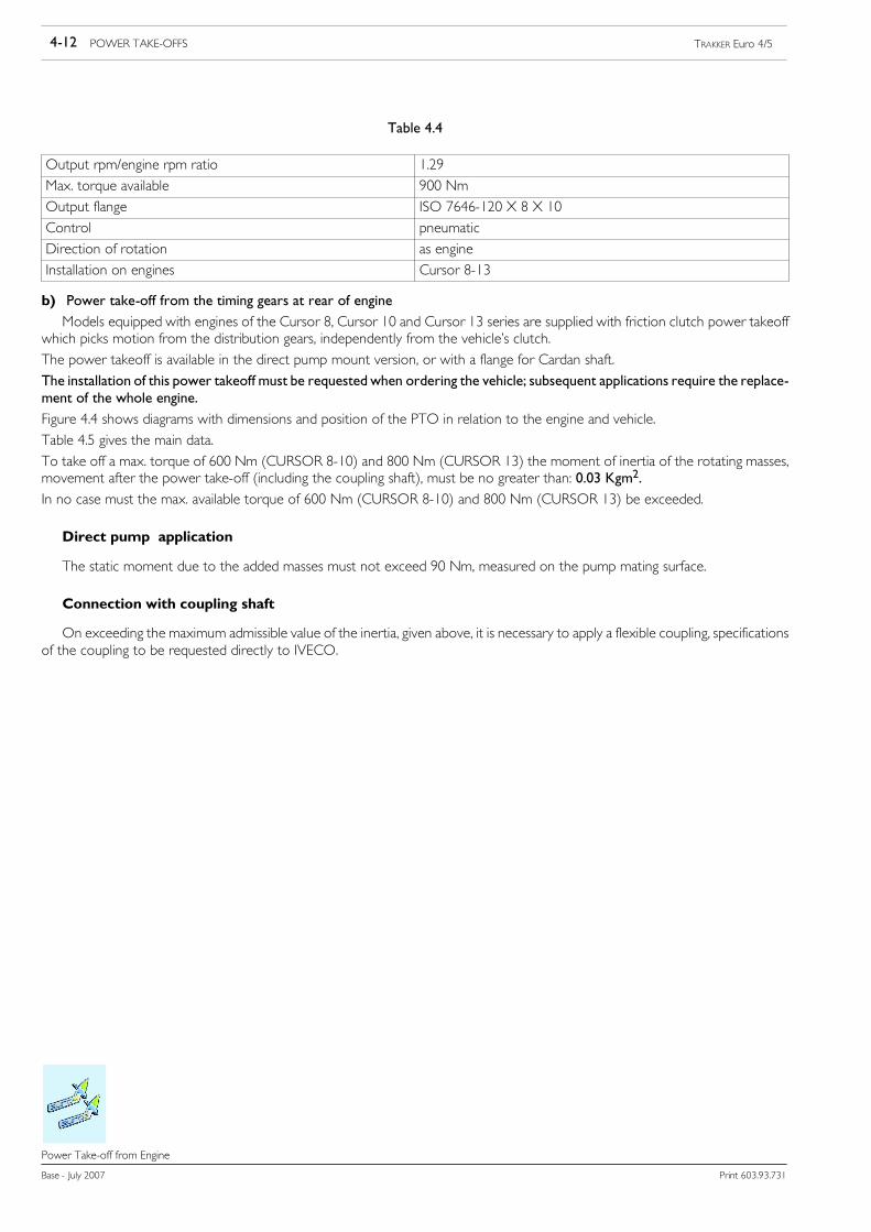
Table 4.4
Output rpm/engine rpm ratio 1.29
Max. torque available 900 Nm
Output flange ISO 7646-120 X 8 X 10
Control pneumatic
Direction of rotation as engine
Installation on engines Cursor 8-13
b) Power take-off from the timing gears at rear of engine
Models equipped with engines of the Cursor 8, Cursor 10 and Cursor 13 series are supplied with friction clutch power takeoffwhich picks motion from the distribution gears, independently from the vehicle’s clutch.
The power takeoff is available in the direct pump mount version, or with a flange for Cardan shaft.
The installation of this power takeoff must be requested when ordering the vehicle; subsequent applications require the replace-ment of the whole engine.
Figure 4.4 shows diagrams with dimensions and position of the PTO in relation to the engine and vehicle.
Table 4.5 gives the main data.
To take off a max. torque of 600 Nm (CURSOR 8-10) and 800 Nm (CURSOR 13) the moment of inertia of the rotating masses,movement after the power take-off (including the coupling shaft), must be no greater than: 0.03 Kgm2.
In no case must the max. available torque of 600 Nm (CURSOR 8-10) and 800 Nm (CURSOR 13) be exceeded.
Direct pump application
The static moment due to the added masses must not exceed 90 Nm, measured on the pump mating surface.
Connection with coupling shaft
On exceeding the maximum admissible value of the inertia, given above, it is necessary to apply a flexible coupling, specificationsof the coupling to be requested directly to IVECO.

POWER TAKE-OFFS 4-13TRAKKER Euro 4/5
Print 603.93.731 Base - July 2007
Power Take-off from Engine
Figure 4.4
91525
(EuroTronic andtraditional transmissions)
Versions available
Pump connectionISO 4 holes (7653)(option 6366)
Flange connectionDIN 10 (option 5367)
position on the vehicle(approx. dimensions)
(Traditional transmissions only, not EuroTronic)
Table 4.5
Type Configuration A / Flange A / Pump B C
Cursor 84x2, 6x4, 8x4 555 mm 589 mm 73 mm 154 mm
Cursor 84x4, 6x6 550 mm 584 mm 216 mm 154 mm
Cursor 134x2, 6x4, 8x4 658 mm 692 mm 117 mm 169 mm
Cursor 134x4, 6x6, 8x8 650 mm 686 mm 257 mm 169 mm
4-14 POWER TAKE-OFFS TRAKKER Euro 4/5
Base - July 2007 Print 603.93.731
Power Take-off from Engine
Multipower
This specific power take-off has the advantage that it is installed by Iveco and allows coupling pumps required for system handlingand remains engaged not only during equipment load/unload operations but also with the vehicle in motion (unless it is disengagedby the operator).
While there are non problems with this particular power takeoff during normal loading and unloading operations, and during vehiclemovement, some problems may occur because of the Multipower rotating speed.
As a matter of fact, the pumps connected to the Multipower, can reach a maximum rotation speed of 1800 r.p.m.; this value in factaccording to the takeoff e multiplication function corresponds to a pump rotation speed of 2400 rpm.
Therefore, in order to avoid problems with the pumps, after the PTO engagement and with the vehicle being driven the rotationspeed of the engine must be limited to 1800 rpm.
Consequently, in order to operate FMO equipment with this type of power takeoff, the vehicle control unit must have the threefollowing function modes enabled:
1) Vehicle in motionWith Multipower engaged and the vehicle in motion, the vehicle control unit must receive the PTO engaged signal.
Acceleration of the vehicle is permitted, but it is not allowed to exceed the 1800 rpm threshold, set in the program of the vehiclecontrol unit.
2) Pump engaged with accelerator de-activatedAfter engagement of the pump, if no part of the equipment is in operation (if no loading and unloading operations are being
preformed and the compactor is not engaged), the vehicle control unit receives the pump engaged signal. The rotating speed, setby the vehicle control unit program, is kept to a minimum and accelerations from the operator are not permitted (if the acceleratorpedal remains de-activated).
This condition can be found even when, the movement of the equipment is interrupted during oper-ation because of an alarm.
During emergencymovements, for example for the return into theprofile of themembers, it is advis-able to carry out the manoeuvres with a reduced motor rotation speed.
NOTE
Remember that with these enabled pump without accelerator request conditions during normal operation may not be frequent:in fact the compactor is always on during normal equipment operation and this implies the accelerator enabling request.
3) Pumps engaged with accelerator activatedAfter engauging the PTO pump andwith the equipment in operation (loading, unloading and compacting operations), the vehicle
control unit receives the accelerator request signal.
The rotating speed set by means of the vehicle control unit, is carried to the optimal value required to obtain the oil flow capacityrequired for equipment operation.
Even in this stage the operator cannot accelerate.
Therefore, three different vehicle rotating speeds and thresholds are required and must be obtained by means of three differentsignals that are to be sent by the equipment to the vehicle control unit.
!FMO equipment without Multipower operate only on function 2 and 3.

POWER TAKE-OFFS 4-15TRAKKER Euro 4/5
Print 603.93.731 Base - July 2007
Power Take-off from Engine
Power take-off from timing gears for Eurotronic 2 transmissions
Figure 4.5
EuroTronic transmissionsare compatible with enginedistribution PTOs providinga flange attachment is used.
DIN 10
OPTION 5367
Flange attachment
Two PTOs specific for EuroTronic transmissions only are provided OPT 7345 - OPT 6369
All PTOs for mechanical transmission can be fitted on EuroTronic transmissions.
Table 4.6 - PTO Specifications
Power take-off
Engine Max. torqueavailable for
Outrpm/engine
Output type Direction ofgavailable fordrawing Nm
rpm/enginerpm ratio Pump conn. Flange conn.
Direction ofrotation
F2BCURSOR 8
600 1,14 ISO 4 holes (7653) DIN 10Oppositeto engine
F3BCURSOR 13
800 1,12 ISO 4 holes (7653) DIN 10Oppositeto engine
PTO can be equipped with a pneumatic disc clutch in oil bath system.NOTE

4-16 POWER TAKE-OFFS TRAKKER Euro 4/5
Base - July 2007 Print 603.93.731
Power Take-off from Engine
Limits of the torque obtainable from the power takeoff according to engine revs
Torque drawing from the power takeoff is described in the following diagrams:
Figure 4.6
91526
Obtainabletorque(Nm)
Engine revs (rpm)CURSOR 8
Vehicle programming
- Vehicle stopped - PTO mode ONTake-off of up to 600 Nm of torque is permitted at engine speeds of over 1100 rpm.
- Vehicle running - PTO mode ON- no limit to the torque obtainable from the power takeoff according to engine revs;- engine idle running set to 800 r.p.m.;- the air supply system pressure fot PTO clutch coupling must be above 8 bars.
Figure 4.7
91527
Obtainabletorque(Nm)
Engine revs (rpm)CURSOR 13
Vehicle programming
- Vehicle stopped - PTO mode ONTorque drawing of 800 Nm is permitted over 1100 r.p.m.
- Vehicle running - PTO mode ON- no limit to the torque obtainable from the power takeoff according to engine revs;- engine idle running set to 700 r.p.m.;- the air supply system pressure for PTO clutch coupling must be above 8 bars.

POWER TAKE-OFFS 4-17TRAKKER Euro 4/5
Print 603.93.731 Base - July 2007
PTO management
PTO management
4.6 PTO management
!Operations which do not comply with the instructions specified by IVECO or made by non qualifiedpersonnel can cause severe damage to on-board systems, effect driving safety and good operation ofthe vehicle and cause considerable damage which is not covered by warranty.
Figure 4.8
0051469t
EM ECU (IT IS LOCATED IN THE ECU HOUSING IN FRONT OF PASSENGER SEAT)

4-18 POWER TAKE-OFFS TRAKKER Euro 4/5
Base - July 2007 Print 603.93.731
PTO management
4.6.1 General Specifications
Two operations are required to operate a PTO:
1) mechanical PTO engagement;
2) PTO mode to be associated to the PTO. See below for PTO mode definitions.
The expression ”PTO active” indicates that the PTO is engaged and that one of the PTO modes is active; otherwise, it is said thatthe PTO is engaged only.
Actions 1) and 2) can be carried out with two separate commands, in 1)-2) sequence.
3) A control carrying out actions 1 and 2 simultaneously
In general, PTO can be engaged by an electric command (triggered by a s olenoid valve) or by a pneumatic command.
4) PTO cutout conditions
!It is important to use the signals available on the bodybuilders connectors (e.g. parking brake applied,stationary vehicle signal, reverse gear not engaged) to ensure correct PTO management and avoidpossible damage to the vehicle’s mechanisms.
These signals must exclusively be taken from the bodybuilders connections, ST14.
Based on required use, the body maker must address to IVECO service for ECU programming (Body Computer, ECU on gearboxif EuroTronic) that, together with EDC, manage PTO operation.
With the assistance of tables contained in para below, the body maker can identify the configuration of the PTO control electronicsystem, herein conventionally called PTO1, 2 and 3. The body maker can choose, at the IVECO assistance network, one of theavailable configurations preset on EASY.
4.6.2 PTO 0 mode (run mode)
In normal operation, an intermediate rpm ratio can be activated to a speed of 30 km/h (important note: the speed regulatorwill trip at speeds exceeding 30 km/h). Press Resume on the steering wheel stalk unit to activate. A new intermediate r.p.m. canbe memorised by the driver by pressing the Resume pushbutton for 3 to 10 seconds, in this case no IVECO Service reprogrammingis required.
The maximum rpm achievable with SET+ is identical for all modes.
The minimum rpm achievable with SET- is identical for all modes. The idle speed adjustment range is exactly the same for all modes.
Settings shown in the following table cannot be changed for PTO 0 mode (drive mode).
POWER TAKE-OFFS 4-19TRAKKER Euro 4/5
Print 603.93.731 Base - July 2007
PTO management
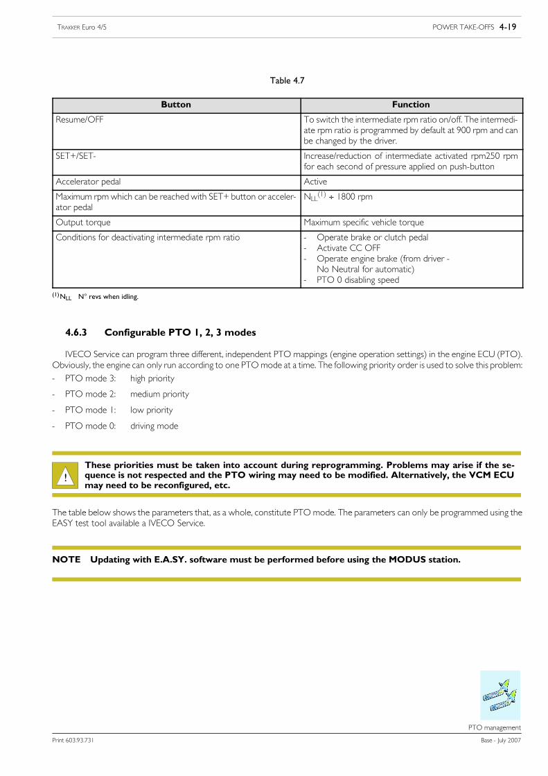
Table 4.7
Button Function
Resume/OFF To switch the intermediate rpm ratio on/off. The intermedi-ate rpm ratio is programmed by default at 900 rpm and canbe changed by the driver.
SET+/SET- Increase/reduction of intermediate activated rpm250 rpmfor each second of pressure applied on push-button
Accelerator pedal Active
Maximum rpm which can be reached with SET+ button or acceler-ator pedal
NLL(1) ÷ 1800 rpm
Output torque Maximum specific vehicle torque
Conditions for deactivating intermediate rpm ratio - Operate brake or clutch pedal- Activate CC OFF- Operate engine brake (from driver -No Neutral for automatic)
- PTO 0 disabling speed
(1)NLL N° revs when idling.
4.6.3 Configurable PTO 1, 2, 3 modes
IVECO Service can program three different, independent PTO mappings (engine operation settings) in the engine ECU (PTO).Obviously, the engine can only run according to one PTO mode at a time. The following priority order is used to solve this problem:
- PTO mode 3: high priority
- PTO mode 2: medium priority
- PTO mode 1: low priority
- PTO mode 0: driving mode
!These priorities must be taken into account during reprogramming. Problems may arise if the se-quence is not respected and the PTO wiring may need to be modified. Alternatively, the VCM ECUmay need to be reconfigured, etc.
The table below shows the parameters that, as a whole, constitute PTO mode. The parameters can only be programmed using theEASY test tool available a IVECO Service.
Updating with E.A.SY. software must be performed before using the MODUS station.NOTE

4-20 POWER TAKE-OFFS TRAKKER Euro 4/5
Base - July 2007 Print 603.93.731
PTO management
Table 4.8
Parameter Possible values
Gradient SET+/SET- 250 rpm for each second of pressure applied on push-but-ton
Maximum N5 of revs that can be reached with SET+, NSET_max NLL ÷ 1800
Torque limitation (3) See Table
Runaway speed regulator gradient 0 ÷ 0,2 rpm/Nm
Use of the CC buttons (Resume/SET+/SET-) Enabled / disabled
Storing of intermediate speed rate Fixed (E.A.SY.)/free (driver)
TIP function, for SET+/SET- (4) 20 rev/TIP (10 ÷ 200 revs/TIP)
PTO mode disabling by means of :the brakethe clutchthe parking brakeneutralthe engine brake (by the driver)the retarderspeed disabling
EnabledEnabledDisabledDisabledEnabledDisabledEnabled
Call-up intermediate speed rate stored with Resume on enablingPTO (7)
Enabled / disabled
Minimum N° of revs that can be reached with SET-, NSET_min > 600 rpm
Maximum speed of the vehicle, above which PTO mode is enabled(intermediate speed rate VZDR_max)
between 1 km/h and 90 km/h
Possible power take-off rate range (1) NLL÷ 2700 rpm (2) per Cursor 8NLL÷ 2340 rpm (2) per Cursor 13
Abbreviations:
NLL Idling rpmNmax Maximum rpmNres Stored rpm press Resume or activate PTO mode to recallNSET_max Maximum rpm achievable with SET+ button identical for all PTO modesNSET_min Minimum rpm achievable with SET
(1) The reference speed is that of the crankshaft, not the PTO. The corresponding PTO rpm must be calculated by means of the PTO reduction ratio.
(2) The following rules refer to intermediate rpm ratio adjustment:- Never drop under the NLL value.- Never exceed the Nmax value.- In general NLL = NSET_min = Nres and Nres = NSET_max = Nmax. If the latter is not true, the engine rpm is limited to Nmax.
(3) See para. 4.6.3.1.
(4) The TIP function (i.e. brief pressure on SET+/SET- toggle button for <1 s) is used to gradually vary the intermediate rpm regulator and the speed regulator.The intermediate rpm regulator will be activated at speed <30 km/h; the speed regulator will be activated at speed > 30 km/h. The speed variation of theintermediate rpm regulator steps are equal to 20 rpm for tip, which corresponds to 1 km/h for the speed regulator.
(5) Active the power take off mode is disengaged when the service brake or the clutch pedals are pressed.Disabled the power take off mode is not disengaged when the service brake or the clutch pedals are pressed.In PTO mode 0, the power take off mode is disengaged when the service brake or the clutch pedals are pressed.
(6) Active the power take off mode is disengaged when the parking brake or the clutch pedals are pressed.Disabled the power take off mode is not disengaged when the parking brake or the clutch pedals are pressed.In PTO mode 0, the power take off mode is not disengaged when the parking brake is engaged.
(7) Active the engine goes automatically to the chosen Nres value for that power take off mode.Disabled the engine remains at the previous rate, to reach the value Nres it is necessary to press the Resume button
(pin 9 and 12 on the 21 pin connector).

POWER TAKE-OFFS 4-21TRAKKER Euro 4/5
Print 603.93.731 Base - July 2007
PTO management
4.6.3.1 Changing the torque curve, maximum rpm and the overrun regulator curve gradient
The following can be limited to mechanically protect the PTO:
- Maximum engine torque to protect against overloading (horizontal section of the curve in Figure 4.9).A straight limitation line (providing a maximum torque value) and a rev number / torque curve already defined by means of 16points can be defined for each motor power.The unit uses the minimum value between the straight line and the curve (See Figure 4.9).
Figure 4.9
114514
1. Resultant curve - 2. Maximum torque straight limitation line - 3. Out of rev curve - 4. Curve points
- Maximum engine rpm to protect against overrun (slanted section of curve in Figure 4.9). This limitation is called ”runaway regula-tor”.
These limitations (maximum torque, intersection point, curve gradient) can be selected independently of each other. The combina-tion of limitations is recommended. In this case, according to the envisaged PTO use, bodybuilders shall select the engine ratio limit(intersection point X) which must be made available to the selected torque.

4-22 POWER TAKE-OFFS TRAKKER Euro 4/5
Base - July 2007 Print 603.93.731
PTO management
The overrun regulator trips when the engine ratio exceeds the intersection point X. Note that the reference speed is that of thecrankshaft, not the PTO. The corresponding PTO rpm must be calculated by means of the PTO reduction ratio.
Figure 4.10
91546
Overrun regulator curvegradient:CURVE A ~0.65 cv/rpmCURVE B ~1 cv/rpmCURVE C ~2 cv/rpm
Maximumtorque [Nm]
Curve B
Curve A
Intersectionpoint X
Curve C
Rpm[rpm]
See example in Figure 4.10:
- Maximum engine torque 600 Nm.
- The standard operation of the PTO is 900 rpm.
- The engine rpm must not exceed 1100 rpm.
- The rpm must be determined for all of the overrun regulator slope.
The slope of the curve for the overrun regulator depends on the particular use of the vehicle. For this reason, when stationary, itis generally sufficient for the overrun regulator to have a steep curve, whereas for the ”driving” mode, this might give rise to rapidchanges in load, which may cause problems.
Power is 1100 rpm and torque is equal to 600 Nm i.e.:
P = (600 Nm x 1100 rpm)/9550 = 69 KW
The available rpm at 600 Nm can be calculated using a steeper overrun regulator (curve C; gradient 2CV/rpm):
1100 rpm - (94CV/2CV/rpm) = 1100 rpm - 47 rpm = 1053 rpm
The available rpm at 600 Nm can be calculated by using an intermediate overrun regulator (curve B; gradient 1CV/rpm):
1100rpm - (94CV/1CV/rpm) = 1100 rpm - 94 rpm = 1006 rpm
The available rpm at 600 Nm can be calculated by using a flat overrun regulator (curve A; gradient 0.65CV/rpm):
1100rpm - (94CV/0.65CV/rpm) = 1100 rpm - 145 rpm = 955 rpm
Engaging rpm regulator variable from 0 and 0.2 rpm*Nm
In the considered example, intermediate stored rpmNres should be adjusted to 900 rpm. This intermediate rpm should be automati-cally activated when PTO mode is engaged.
The example shows the impact of the overrun regulator. Depending on the usage the chosen torque of 600 Nm is available upto 1055 rpm, 1005 rpm or 955 rpm.
The same is true in reverse, when engine torque, intersection point X and overrun regulator curve inclination are predefined, it ispossible to calculate the final rpm speed.

POWER TAKE-OFFS 4-23TRAKKER Euro 4/5
Print 603.93.731 Base - July 2007
PTO management
!Themaximum rpmNmax is a theoretical value. This is the rpm at which the ECU reduces the injectedamount of fuel at 0 mg/stroke. Considering that all engines, according to the rpm (engine hot and noload) need 20÷30 mg/stroke of fuel to maintain the rpm, this theoretical value Nmax is never reached.According to the slope of the overrun regulator, the rpm actually reached is 10÷40 rpm lower. You areadvised to define overrun ratio by means of practical tests if this is likely to effect the application.
4.6.4 Intermediate rpm regulator
Maximum intermediate rpm regulator setting that can be achieved with SET+, NSET_max
TThe TIP function, i.e. a very short press (< 1s) on the SET+/SET- keys, allows a gradual change in the intermediate speed regula-tor or speed regulator. With speed <V0 (max speed of PTO mode) km/h, the intermediate rpm governor can be activated.
With speed >V0 km/h, the speed governor is activated. The change for the intermediate speed regulator is equal to 20 rpm rpmfor each TIP i.e. 1 km/h for each TIP with the speed regulator.
The intermediate rpm or speed value is modified continuously by pressing the SET+ and SET- buttons for more than (>1 s). Theeffective rpm and effective speed when the SET+ and SET- buttons are released and stored as the new value.
Function TIP with SET + and SET - can be disengaged. This configuration is applicable to all PTO modes simultaneously (drive mode0, PTOmode 1, 2 and 3). Function TIP disengagement activates the speed limiter operation limitation. Therefore, this change shouldonly be operated after an in-depth analysis.
This function is provided for the regulation of hydraulic units.NOTE
Increasing/decreasing rpm with SET+/SET-
The intermediate rpm regulator value can be changed by pressing the SET+/SET- buttons for more than (>1 s) or when theTIP function is deactivated by a certain speed (engine rpm increase/decrease per second). The time interval for this change can becalculated using the following formula:
Time required [s] = Rpm difference [rpm/s] / rpm increase per second [rpm/s /s]
Example: take the intermediate rpm from 800 rpm to 1800 rpm using the SET+ button. The difference in rpm is equal to 1000 rpm,consequently:
- At a speed of 250 rpm/s, the time interval is 1000/250 = 4s
Activating/deactivating the accelerator pedal
The accelerator pedal is always active in normal driving mode (PTO mode 0). The accelerator pedal can be deactivated in PTOmodes 1, 2 or 3. In this case, PTO engine regulation will ignore the accelerator pedal. If the accelerator pedal is active, the enginerpm can be increased by means of the pedal to the maximum rpm Nmax valid at the time.
4-24 POWER TAKE-OFFS TRAKKER Euro 4/5
Base - July 2007 Print 603.93.731
PTO management
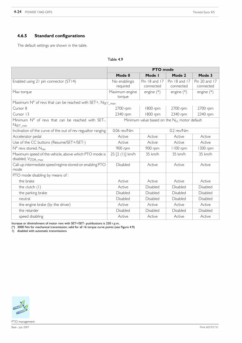
4.6.5 Standard configurations
The default settings are shown in the table.
Table 4.9
PTO mode
Mode 0 Mode 1 Mode 2 Mode 3
Enabled using 21 pin connector (ST14) No enablingisrequired
Pin 18 and 17connected
Pin 18 and 17connected
Pin 20 and 17connected
Max torque Maximum enginetorque
engine (*) engine (*) engine (*)
Maximum N° of revs that can be reached with SET+, NSET_maxCursor 8 2700 rpm 1800 rpm 2700 rpm 2700 rpm
Cursor 13 2340 rpm 1800 rpm 2340 rpm 2340 rpm
Minimum N° of revs that can be reached with SET-,NSET_min
Minimum value based on the NLL motor default
Inclination of the curve of the out of rev regualtor ranging 0.06 rev/Nm 0.2 rev/Nm
Accelerator pedal Active Active Active Active
Use of the CC buttons (Resume/SET+/SET-) Active Active Active Active
N° revs stored, Nres 900 rpm 900 rpm 1100 rpm 1300 rpm
Maximum speed of the vehicle, above which PTO mode isdisabled, VZDR_max
25 [2 (1)] km/h 35 km/h 35 km/h 35 km/h
Call-up intermediate speed regime stored on enabling PTOmode
Disabled Active Active Active
PTO mode disabling by means of :
the brake Active Active Active Active
the clutch (1) Active Disabled Disabled Disabled
the parking brake Disabled Disabled Disabled Disabled
neutral Disabled Disabled Disabled Disabled
the engine brake (by the driver) Active Active Active Active
the retarder Disabled Disabled Disabled Disabled
speed disabling Active Active Active Active
Increase or diminishment of motor revs with SET+/SET- pushbuttons is 250 r.p.m..(*) 3000 Nm for mechanical transmission; valid for all 16 torque curve points (see Figure 4.9)1) disabled with automatic transmissions

POWER TAKE-OFFS 4-25TRAKKER Euro 4/5
Print 603.93.731 Base - July 2007
PTO management
4.6.6 Specific indications: correlation between the VCM configuration and the installed powertake offs
There is no direct connection between the PTO power take off mode (which can be activated using the 21-pin connector) andthe power take offs physically fitted to the vehicle. Therefore, the bodybuilder can define the necessary connections as suits him.
This set up therefore makes it possible to use the power take off(s) with the various PTO configurations (for example, for particularwork cycles). Should a work cycle be established, for example, in which the fitted power take off is made to operate in differentconditions, then up to a maximum of 3 modes for the PTO power take off can be used. The corresponding PTO power take offmodes must be activated from the body/ancillary at the relevant times.
In a similar way, it is possible to correlate an PTO power take off mode even without there being a power take off physically fittedto the vehicle, or conversely when there is more than one fitted.
4.6.7 Engaging the power take off
The power take-offs fitted on the gearbox can only be engaged with the clutch fully pressed.
The PTO mode power take-offs, on the other hand, can be enabled independent of the above.
4.6.8 With Allison Gearbox
When the vehicle has an Allison gearbox, the selection of the power take off is co-ordinated by the gearbox central controlunit. The operation uses the following procedure:
- request to engage the power take off (the gearbox central control unit checks the internal conditions so that the operation canbe effected safely: engine speed less than 900 rpm and output speed from the gearbox less than 250 rpm);
- the solenoid valve used to engage the power take off is activated by the central control unit;
- a check is made that the power take off is functioning safely (output speed from the gearbox less than 300 rpm).The button for engaging the power take off is located in the central section of the dashboard.
!Before engaging the power take off, the gearbox central control unit checks a number of parameters(engine speed is less than 900 rpm and output speed from the gearbox is less than 250 rpm).
If all the necessary conditions inside the gearbox are satisfied, the Allison gearbox central control unitautomatically engages the power take off. The restrictions (end speed, maximum torque etc) for thePTO power take off mode selected therefore remain valid even while the engagement takes place.
Certain values may be modified by Allison Customer Assistance, as required by the bodybuilder.
4.6.9 Use of the power take-off with vehicle in motion
If restrictions are not required (e.g. restrictions on torque, reduced maximum number of engine revs, etc) when the power takeoff is engaged, it is not necessary to use any PTO power take off mode.
In this case, however, the engine power available for running the vehicle is reduced (given that power is being taken simultaneouslyby the ancillary). This could lead to acceleration problems. In typical usages (e.g. cement mixers, refuse collection vehicles etc) thisproblem can be minimised by increasing the idling speed. This increased number of revs would, however, also then be present evenwhen the power take off was disengaged. In general, a reduction in the maximum torque in this field of operation would not beconsidered sensible.
If, however, restrictions are required (e.g. restrictions on torque, reducedmaximum number of engine revs, etc) then an PTO powertake off mode should be used.

4-26 POWER TAKE-OFFS TRAKKER Euro 4/5
Base - July 2007 Print 603.93.731
PTO management
!Particularly when the vehicle is operational, care must be taken to ensure that if an PTO power takeoff mode is activated, then the stored intermediate number of revs must also be activated at the sametime. This could, however, result in an unexpected increase in vehicle speed. It is the bodybuilder’s re-sponsibility to ensure that the chosen solution is safe.
The engagement or disengagement of the power take off depends both on the power take off chosen and the requirements ofthe bodybuilder.
Regarding vehicle operation (up to a maximum speed of 30 km/h) with an increased number of revs when the power take off isengaged. For a range of applications, (e.g. use of a tipping body, cement mixer, refuse collection etc) higher revs are also requiredduring operation. This can be achieved using the following set up:
- Stored intermediate number of revs Nres: fixed programming
- Intermediate number of revs (Nres): as defined by the bodybuilder
- Disengagement of the intermediate number of revs: deactivated via the clutch or brake pedals
- Accelerator pedal: activated
- CC Buttons: deactivated
In this way, the engine can only operate again when the accelerator pedal is regulated between the stored intermediate numberof revs, Nres, and the maximum number of revs, Nmax. If VZDR-aus is ever reached, the intermediate number of revs and thereforealso the increase in revs is deactivated.
Changing the stored intermediate number of revs Nres
The intermediate number of revs can be modified separately for each PTO power take off mode.It is necessary to distinguish between two possibilities:
1) Fixed programming (E.A.SY.)For mode 0 power takeoff (driving mode), this mode is not available. A modification is only possible by reprogramming theE.A.SY. test tool at IVECO Service
2) Free programming (by the driver)To modify the intermediate number of revs, the following procedure is used:a) select the particular PTO power take off mode whose intermediate number of revs are to beb) set the desired intermediate number of revs using the SET+/SET- button;c) press and hold CC Resume for 3 to 10 seconds.
Updating with E.A.SY. software must be performed before using the MODUS station.NOTE
The minimum number of revs reachable can be regulated by means of the SET-, NSET_min pushbutton forPTO 0
The idling speed must only be set when the engine is warm. There are three stages in the process:
1) Idle running actuationThe engine must operate at idling speed.
- Actuate the service brake (until the end of adjustment)
- Press and hold the Resume pushbutton for 3 to 7 seconds.Immediately afterwards, the idling speed reduces automatically to the minimum value. Actuate the service brake (until the endof adjustment).
POWER TAKE-OFFS 4-27TRAKKER Euro 4/5
Print 603.93.731 Base - July 2007
PTO management
2) Modifying the minimum idling speedIt is possible to regulate the idling speed by intervals of 20 min-1 using the SET+ or SET- buttons.
3) Recording the minimum idling speed (in revs)The speed is stored by pressing the CC Resume button again (for a period of time ranging between 3 and 7 seconds.)
Influence of the exhaust brake on the intermediate number of revs
The engine brake can be activated by:
1) Pressing the engine brake pedal (on the cab’s floor)
2) Pressing the brake pedal (when the brake is pressed the engine brake is automatically activated).
3) Pressing the accelerator pedal (at idling speed the engine brake is automatically activated).Selections can be made by means of a switch placed on the dashboard.
If the engine brake is activated in any manner as described above (2 or 3) the governor deactivates automatically.
When the engine brake pedal is pressed, the CC push button functions (CC OFF/Resume/SET+/SET-) are disabled.
Simultaneous operation of SET+ and SET-
These functions are mutually exclusive. Should both be activated simultaneously, then for safety reasons the CC Off button isactivated immediately or after 500 ms. If, however, the buttons were pressed simultaneously, the engine’s EDC central control unitrecognises an error after 500 ms.
Second speed limiter
This function can be activated independently of the various PTO power take off modes (driving mode 0, power take off modes1, 2 and 3). IVECO Service can set the value using a E.A.SY. station. The seond speed limiter is enabled by contact towards K15on pin 1 of the 9 pin connector (ST14B).
The use of the MODUS station must take place after an upgrade is run using E.A.SY. softwareNOTE

4-28 POWER TAKE-OFFS TRAKKER Euro 4/5
Base - July 2007 Print 603.93.731
EM (Expansion Module)
EM (Expansion Module)
4.7 EM (Expansion Module)
The optional 4572, EM (Expansion Module), is available on all the new Trakker.
The EM control unit can be used for electrical management of the PTO and for special applications. Also provides special gatewayssuch as: trailer interface ISO11992-3 (TT) and CAN OPEN interface (BB in development phase).
Diagnostics is possible via CAN line and K line.
The wiring diagram for the Expansion Module hardware is shown in Figure 4.11, and the block diagram of the hardware structureis shown in Figure 4.12.
Figure 4.11
0052948t

POWER TAKE-OFFS 4-29TRAKKER Euro 4/5
Print 603.93.731 Base - July 2007
EM (Expansion Module)
Figure 4.12
116699
The EM control unit allows the PTO activation and deactivation conditions to be set.
The connections on ST60, ST62 and ST63 must be carried out by the fitter so as to activate and display on IC the activation ofthe PTO.
The predefined set conditions for Trakker Euro 4-5 are:
4.7.1 Connections
Table 4.10 - PTO mode request: ST13
PTO 1 pin 18
PTO 2 pin 19
PTO 3 pin 20
To carry out the request, close the pins on the earth of pin 17.
Table 4.11 - PTO IN/OUT: ST60 PTO1, ST62 PTO2, ST63 PTO3
pin 1 PTO feed-back
pin 2 PTO actuator (solenoid valve control)
pin 3 PTO enabling
pin 4 Ground

4-30 POWER TAKE-OFFS TRAKKER Euro 4/5
Base - July 2007 Print 603.93.731
EM (Expansion Module)
4.7.2 PTO activation/deactivation conditions:
These conditions can be modified in Customer Service.NOTE
Table 4.12
State of brake pedal pressed/not pressed
State of parking brake engaged/not engaged
tate of clutch pedal pressed/not pressed
State of pressure switch open/closed
State of the gear neutral/not in neutral/reverse
Allowed set of gears
Allowed engine revolutions
Allowed vehicle speeds
Maximum temperature of coolant
Maximum percentage of clutch slipping
4.7.3 No PTO installed or provisions for PTO:
Default configuration
PTO options: 5439, 5194, 6368, 1483, 1484.
Only the programming of the engine revolutions by the VCM is required.The switches select the three rpm modes:
PTO 1 PTO mode 1 900 [tr/min]
PTO 2 PTO mode 2 1100 [tr/min]
PTO 3 PTO mode 3 1300 [tr/min]
4.7.4 PTO Multipower
Default configuration
PTO option: 2395 for all gearboxes.
These conditions can be modified in Customer Service.NOTE

POWER TAKE-OFFS 4-31TRAKKER Euro 4/5
Print 603.93.731 Base - July 2007
EM (Expansion Module)
Table 4.13 - Activation conditions
State of engine OFF
Pressure switch closed
State of vehicle stationary
Coolant temperature < 120 [°C]
Table 4.14 - Deactivation conditions
Coolant temperature > 120 [°C]
4.7.5 PTO manual gearbox with electric engagement
Default configuration
PTO options: 6392, 6393, 1459, 1505, 1507, 1509, 6384, 14553, 14554 for all manual gearboxes.
These conditions can be modified in Customer Service.NOTE
Table 4.15 - Activation conditions
State of engine ON
Coolant temperature < 120 [°C]
Table 4.16 - Deactivation conditions
State of vehicle OFF
Vehicle speed > 25 [km/h]
Coolant temperature > 120 [°C]

4-32 POWER TAKE-OFFS TRAKKER Euro 4/5
Base - July 2007 Print 603.93.731
EM (Expansion Module)
4.7.6 PTO FOCSA
Default configuration
These conditions can be modified in Customer Service.NOTE
Table 4.17 - Activation conditions
State of engine ON (always enabled)
Table 4.18 - Deactivation conditions
State of engine OFF
4.7.7 Engine PTO
Default configuration
These conditions can be modified in Customer Service.NOTE
Table 4.19 - Activation conditions
State of engine ON
State of vehicle stationary
Coolant temperature < 120 [°C]
Table 4.20 - Deactivation conditions
State of vehicle OFF
Coolant temperature > 120 [°C]

POWER TAKE-OFFS 4-33TRAKKER Euro 4/5
Print 603.93.731 Base - July 2007
EM (Expansion Module)
4.7.8 PTO Eurotronic 2 transmission
Default configuration
These conditions can be modified in Customer Service.NOTE
Table 4.21 - Activation conditions
State of gearbox enabled
State of engine ON
State of vehicle stationary
Coolant temperature < 120 [°C]
Table 4.22 - Deactivation conditions
State of vehicle OFF
Coolant temperature > 120 [°C]
4.7.9 PTO TRANSFER BOX
Default configuration
These conditions can be modified in Customer Service.NOTE
Table 4.23 - Activation conditions
Clutch state released
State of engine ON
State of vehicle stationary
Coolant temperature < 120 [°C]
Table 4.24 - Deactivation conditions
State of vehicle OFF
Coolant temperature > 120 [°C]

4-34 POWER TAKE-OFFS TRAKKER Euro 4/5
Base - July 2007 Print 603.93.731
EM (Expansion Module)

SPECIAL INSTRUCTIONS FOR ELECTRONIC SUBSYSTEMS 5-1TRAKKER Euro 4/5
Print 603.93.731 Base - July 2007
Index
Index
SECTION 5
Special instructions for electronic subsystems
Page
5.1 Multiplex system (MUX) 5-3
5.1.1 Description of MUX ECUs 5-3
5.1.1.1 Instrument Cluster (IC) 5-4
5.1.1.2 Iveco Body Controller (IBC3) 5-4
5.1.1.3 Terminal board (electrical circuit passage) 5-5
5.1.1.4 MET frame module control unit 5-5
5.2 Bodybuilder connectors 5-6
5.2.1 In the cab 5-6
5.2.2 On frame 5-11
5.2.3 Truck/trailer connectors 5-14
5.3 Electrical circuit modifications 5-16
5.3.1 Introduction 5-16
5.3.2 Wiring harness length 5-16
5.3.3 Repositioning ECUs 5-19
5.3.4 Disconnecting ECUs 5-20
5.4 FMS 5-21

5-2 SPECIAL INSTRUCTIONS FOR ELECTRONIC SUBSYSTEMS TRAKKER Euro 4/5
Base - July 2007 Print 603.93.731
Index

SPECIAL INSTRUCTIONS FOR ELECTRONIC SUBSYSTEMS 5-3TRAKKER Euro 4/5
Print 603.93.731 Base - July 2007
Multiplex system (MUX)
55555.
Multiplex system (MUX)
This chapter contains important information concerning the electronic network (MUX) installed onTrakker.
NOTE
5.1 Multiplex system (MUX)
Trakker is equipped with an innovative electronic system, Multiplex (EASY MUX). The system electronically manages and con-trols the vehicle subsystems on CAN lines. The most important characteristics of MUX devices are shown in the paragraphs thatfollow.
5.1.1 Description of MUX ECUs
The location (Figure 5.1) and functions of the MUX ECUs (electronic control units) installed in the vehicle are illustrated belowfor a better understanding of the IVECO Multiplex system.
!Devices or electrical circuits cannot be directly connected to the ECUs described below. Always onlyuse the connectors and special interfaces listed in the following paragraphs (bodybuilder connectors5.2).
117470
Figure 5.1
1. RFC on trucks - 2. RFC on tractors - 3. BM Bed Module - 4. AHT.A (additional heater) - 5. IBC3 - 6. Terminal board -7. CC Climate Control - 8. AHT.W (additional coolant heater) - 9. FFC Front Frame Computer - 10. IC Instrument Cluster -
11. DDM Drive Door Module - 12. PDM Passenger Door Module - 13. EM (Expansion Module)

5-4 SPECIAL INSTRUCTIONS FOR ELECTRONIC SUBSYSTEMS TRAKKER Euro 4/5
Base - July 2007 Print 603.93.731
Multiplex system (MUX)
5.1.1.1 Instrument Cluster (IC)
The instrument cluster (IC) is the main interface between the driver and the vehicle electronic subsystems. All information onsystem status and error messages concerning single subsystems are shown on the instrument cluster (see specific documentationfor diagnostics).
Figure 5.2
98895
INSTRUMENT CLUSTER (IC)
5.1.1.2 Iveco Body Controller (IBC3)
Figure 5.3 shows the Body Computer which processes all the input and output signals for controlling vehicle subsystems. Thisfunction is assisted by an ancillary ECU, called Cab Module.
Figure 5.3
0052299t
IBC3 CONTROL UNIT
SPECIAL INSTRUCTIONS FOR ELECTRONIC SUBSYSTEMS 5-5TRAKKER Euro 4/5
Print 603.93.731 Base - July 2007
Multiplex system (MUX)
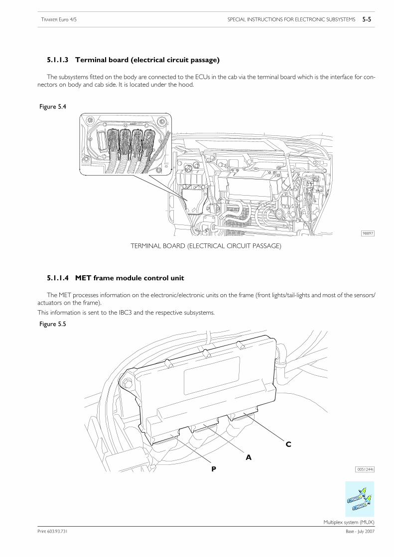
5.1.1.3 Terminal board (electrical circuit passage)
The subsystems fitted on the body are connected to the ECUs in the cab via the terminal board which is the interface for con-nectors on body and cab side. It is located under the hood.
Figure 5.4
98897
TERMINAL BOARD (ELECTRICAL CIRCUIT PASSAGE)
5.1.1.4 MET frame module control unit
The MET processes information on the electronic/electronic units on the frame (front lights/tail-lights and most of the sensors/actuators on the frame).
This information is sent to the IBC3 and the respective subsystems.
Figure 5.5
0051244t

5-6 SPECIAL INSTRUCTIONS FOR ELECTRONIC SUBSYSTEMS TRAKKER Euro 4/5
Base - July 2007 Print 603.93.731
Bodybuilder connectors
Bodybuilder connectors
5.2 Bodybuilder connectors
The various connectors for bodybuilders are described in detail in the following paragraphs.
5.2.1 In the cab
The main connectors available for use by bodybuilders are ST14A and ST14B, which are blue.
They are located inside the cab, passenger side (see Figure 5.6); 21 contacts and 9 contacts. The terminal function is described inTable 5.1.
Figure 5.6
117471
ST14 CONNECTORS INSIDE CAB (PASSENGER SIDE)
ST14AST14B

SPECIAL INSTRUCTIONS FOR ELECTRONIC SUBSYSTEMS 5-7TRAKKER Euro 4/5
Print 603.93.731 Base - July 2007
Bodybuilder connectors
21 pin connector (brown): ST14A
Male coupling (AMP) parts picking number: 41200684Female coupling (MCP 2.8) parts picking number: 504163549
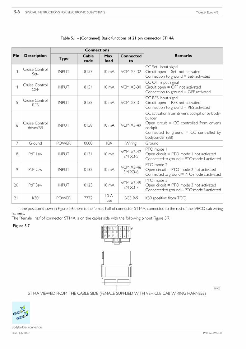
Table 5.1 - Basic functions of 21 pin connector ST14A
Connections
Pin DescriptionType
Cablecode
Max.load
Connectedto
Remarks
1Enginecranking
INPUT 8892 10 mA VCM X3-27
Connected to ground = engine cranking (thesignal must be permanently active for thestarter motor to turn)Open circuit = no action
2 Engine stopping INPUT 0151 10 mA VCM X3-26
Connected to ground = engine shutdown (ashort activation period is sufficient to stop theengineOpen circuit = no action
3 Service brake OUTPUT 1165 200 mA VCM X1-13Service brake pressed indicator signal0 V = service brake not pressed+24 V = service brake pressed
4Vehiclestationary
OUTPUT 5515 200 mA IBC3 E-15Vehicle parked indicator signal0 V = vehicle in motion+24 V = vehicle parked
5 Handbrake OUTPUT 6656 200 mA VCM X1-10Handbrake engaged indicator signal0 V = parking brake not engaged+24 V = parking brake engaged
6 Not connected
7 Vehicle speed OUTPUT 5540 10 mA M/DTCO B7 Pulse signal
8 Engine status OUTPUT 7778 200 mA IBC3 E-14
Engine status indication signal(information D+)0 V = engine off+24 V = engine running
9 Neutral OUTPUT 8050 200 mA VCM X1-7Gearbox in neutral indicator signal0 V = neutral not engaged+24 V = neutral engaged
10 Reverse gear OUTPUT 2268 200 mA IBC3 E-16Reverse engaged indicator signal0 V = reverse engaged+24V = reverse not engaged
11 K15 POWER 8871 3A IBC3 B-1 K15 (ignition-operated power point)
12Cruise Control
Set+INPUT 8156 10 mA VCM X3-33
CC Set+ input signalCircuit open = Set+ not activatedConnection to ground = Set+ activated
5-8 SPECIAL INSTRUCTIONS FOR ELECTRONIC SUBSYSTEMS TRAKKER Euro 4/5
Base - July 2007 Print 603.93.731
Bodybuilder connectors
Table 5.1 - (Continued) Basic functions of 21 pin connector ST14A
Connections
Pin DescriptionType
Cablecode
Max.load
Connectedto
Remarks
13Cruise Control
Set-INPUT 8157 10 mA VCM X3-32
CC Set- input signalCircuit open = Set- not activatedConnection to ground = Set- activated
14Cruise Control
OFFINPUT 8154 10 mA VCM X3-30
CC OFF input signalCircuit open = OFF not activatedConnection to ground = OFF activated
15Cruise Control
RESINPUT 8155 10 mA VCM X3-31
CC RES input signalCircuit open = RES not activatedConnection to ground = RES activated
16Cruise Controldriver/BB
INPUT 0158 10 mA VCM X3-49
CC activation from driver’s cockpit or by body-builderOpen circuit = CC controlled from driver’scockpitConnected to ground = CC controlled bybodybuilder (BB)
17 Ground POWER 0000 10A Wiring Ground
18 PdF 1sw INPUT 0131 10 mAVCM X3-47EM X3-5
PTO mode 1Open circuit = PTO mode 1 not activatedConnected to ground= PTOmode 1 activated
19 PdF 2sw INPUT 0132 10 mAVCM X3-46EM X3-6
PTO mode 2Open circuit = PTO mode 2 not activatedConnected to ground= PTOmode 2 activated
20 PdF 3sw INPUT 0123 10 mAVCM X3-45EM X3-7
PTO mode 3Open circuit = PTO mode 3 not activatedConnected to ground= PTOmode 3 activated
21 K30 POWER 777210 Afuse
IBC3 B-9 K30 (positive from TGC)
In the position shown in Figure 5.6 there is the female half of connector ST14A, connected to the rest of the IVECO cab wiringharness.The ”female” half of connector ST14A is on the cables side with the following pinout Figure 5.7.
Figure 5.7
98903
ST14A VIEWED FROM THE CABLE SIDE (FEMALE SUPPLIED WITH VEHICLE CAB WIRING HARNESS)

SPECIAL INSTRUCTIONS FOR ELECTRONIC SUBSYSTEMS 5-9TRAKKER Euro 4/5
Print 603.93.731 Base - July 2007
Bodybuilder connectors
9 pin connector (yellow): ST14B
Male coupling parts picking number: 41200681Female coupling parts picking number: 504163549
Table 5.2 - Basic functions of 9 pin connector ST14B
Connections
Pin DescriptionType
Cablecode
Max.load
Connectedto
Remarks
1Second speed
limiterINPUT 0172 10 mA VCM X3-13
Second speed limiter activationOpen circuit = second speed limiter notactivatedConnected to 24V = second speed limiteractivated
2 Not used
3 Clutch status OUTPUT 9963 200 mA VCM X1-12Clutch activated indicator signalOpen circuit = clutch not activatedConnection to ground = clutch activated
4 PTS OUTPUT 5542 200 mA VCM X1-14PTS = programmable speed threshold0 V = PTS not activated+24 V = PTS activated
5 Hazard lights INPUT 1113 10 mA IBC3 E4Connected to ground = hazard lights onOpen circuit = no action
6 For future use
7 For future use
8 Engine speed signal OUTPUT 5587 10 mA ECM 33 Pulse signal
9K58: Exterior light-ing power line
OUTPUT 3333 5 A IBC3 E240 V = lights off+24 V = lights on (parking, low beams, highbeams)
The female coupling of connector ST14B connected to the rest of the IVECO wiring is located in the portion indicatedin Figure 5.8.
The female coupling of ST14B is present on the wiring side with the following pin arrangement (Figure 5.8).
Figure 5.8
0051309t
ST14B VEW OF PINOUT SIDE

5-10 SPECIAL INSTRUCTIONS FOR ELECTRONIC SUBSYSTEMS TRAKKER Euro 4/5
Base - July 2007 Print 603.93.731
Bodybuilder connectors
To take the signals required by the conversion it is necessary to procure (from the IVECO Service Network) the ”male” halfof connector ST14A and ST14B (spares P/N can be obtained from drawing n˚ 41200692) to which a wire can be connected foreach of the 21 pins (Figure 5.9) the functions of which are described in the previous pinout.
!Avoid all types of connections to the female connector which could create situations of danger withrisks for the on-board systems, compromising running safety and proper operation of the vehicle andcausing damage that is not covered by the contractual IVECO warranty.
Figure 5.9
ST14B VIEW OF BODYBUILDERS’ CABLE SIDE
98904
CABLE
BODY-
BUILDERS’
The guarantee of a connection made according to standards is assured in the case of a complete connection (Figure 5.10).
Figure 5.10
0051309t
ST14B VIEW FROM CAB SIDE

SPECIAL INSTRUCTIONS FOR ELECTRONIC SUBSYSTEMS 5-11TRAKKER Euro 4/5
Print 603.93.731 Base - July 2007
Bodybuilder connectors
5.2.2 On frame
The following connectors are provided on the chassis:
- ST 52 (ST 81 in previous range)
- ST 64 (for specific use by customer)
- ST 90 (PTO connection, manual transmission) / ST 67 (PTO connection, from EuroTronic gearbox) still present butdestined for unused modifications
- ST 91 connector for PTO1
- ST 92 connector for PTO2
- ST 93 connector for PTO3
Figure 5.11
TERMINAL PART OF CHASSIS: CONNECTORS ST52 / ST64 (RIGHT HAND SIDE CLOSE TO REAR AXLE)
98902
Table 5.3 - ST52 (see Figure 5.11)
Terminal Description Wirenumber
Max. load Connectedto
Remarks
1 K15 for BB 8871 10A RFCJ1/A-2 K15 for BB, output is short-circuit protected
2 Free For future use
3 K58; external lights 3333 5A RFCJ2/A-06 0 V = lights off 1)+24 V = lights on
4 Second speed limiter(adjusted to 30 km/h)
0172 RFCJ2/B-11 Second speed limiter activated [SL]Wire open = 2nd SL not activatedGround = 2nd SL active
1) +24 V when:
- K15 OFF and side markers on
- K15 ON and side markers on
- K15 ON and lights on (dipped beam and main beam)

5-12 SPECIAL INSTRUCTIONS FOR ELECTRONIC SUBSYSTEMS TRAKKER Euro 4/5
Base - July 2007 Print 603.93.731
Bodybuilder connectors
Table 5.4 - ST64 (see Figure 5.11)
5-pin connector
For general use by bodybuilders: four terminals in the 15-pole connector can be used for the trailer (72010).
Terminal Description Circuitcode
Connected to(Source/Destination)
Circuit description
1 - 8021 terminal 15, 72010 15-pole power, terminal pin 10
2 - 7021 terminal 14, 72010 15-pole power, terminal pin 12
3 - 6021 terminal 10, 72010 15-pole power, terminal pin 14
4 K15 8075 ST52/1 E RFC J1/A02
5 - 8075 terminal 11, 72010 15-pole power, terminal pin 11
Table 5.5 - ST91 (right-hand side near transmission, see Figure 5.12)
Terminal Description Wirenumber
Max. load Connectedto
Remarks
1 PTO counter-reaction 6131 - EM X3-8 PTO feedback signalWire open = PTO not engagedGround = PTO engaged
2 PTO control 9131 1,6 A EM X1-1 For electrical PTO activation0 V = solenoid valve not activated+24 V = solenoid valve activated
3 PTO enablement 0391 - EM X3-11 PTO sensor may be disabled/may be disabledWire open = PTO not engagedGround = PTO engaged
4 Ground 0000 11 A Ground (ground to middle of chassis)
1) Two input conditions can be detected:Condition 1 = Wire openCondition 2 =GroundActive signal condition selected via EASYUsed only for pressure switch detection with Multipower PTO and Engine PTO.Can be used as additional digital input for other applications managed by MUX PTO control.
SPECIAL INSTRUCTIONS FOR ELECTRONIC SUBSYSTEMS 5-13TRAKKER Euro 4/5
Print 603.93.731 Base - July 2007
Bodybuilder connectors
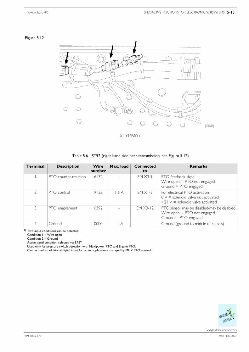
Figure 5.12
ST 91/92/93
98907
Table 5.6 - ST92 (right-hand side near transmission, see Figura 5.12)
Terminal Description Wirenumber
Max. load Connectedto
Remarks
1 PTO counter-reaction 6132 - EM X3-9 PTO feedback signalWire open = PTO not engagedGround = PTO engaged
2 PTO control 9132 1,6 A EM X1-3 For electrical PTO activation0 V = solenoid valve not activated+24 V = solenoid valve activated
3 PTO enablement 0392 - EM X3-12 PTO sensor may be disabled/may be disabledWire open = PTO not engagedGround = PTO engaged
4 Ground 0000 11 A Ground (ground to middle of chassis)
1) Two input conditions can be detected:Condition 1 = Wire openCondition 2 = GroundActive signal condition selected via EASYUsed only for pressure switch detection with Multipower PTO and Engine PTO.Can be used as additional digital input for other applications managed by MUX PTO control.
5-14 SPECIAL INSTRUCTIONS FOR ELECTRONIC SUBSYSTEMS TRAKKER Euro 4/5
Base - July 2007 Print 603.93.731
Bodybuilder connectors
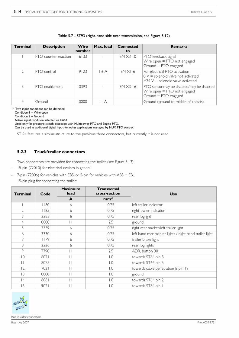
Table 5.7 - ST93 (right-hand side near transmission, see Figura 5.12)
Terminal Description Wirenumber
Max. load Connectedto
Remarks
1 PTO counter-reaction 6133 - EM X3-10 PTO feedback signalWire open = PTO not engagedGround = PTO engaged
2 PTO control 9123 1,6 A EM X1-6 For electrical PTO activation0 V = solenoid valve not activated+24 V = solenoid valve activated
3 PTO enablement 0393 - EM X3-16 PTO sensor may be disabled/may be disabledWire open = PTO not engagedGround = PTO engaged
4 Ground 0000 11 A Ground (ground to middle of chassis)
1) Two input conditions can be detected:Condition 1 = Wire openCondition 2 = GroundActive signal condition selected via EASYUsed only for pressure switch detection with Multipower PTO and Engine PTO.Can be used as additional digital input for other applications managed by MUX PTO control.
ST 94 features a similar structure to the previous three connectors, but currently it is not used.
5.2.3 Truck/trailer connectors
Two connectors are provided for connecting the trailer (see Figura 5.13):
- 15-pin (72010) for electrical devices in general
- 7-pin (72006) for vehicles with EBS, or 5-pin for vehicles with ABS + EBL.
15-pin plug for connecting the trailer:
Terminal CodeMaximumload
Transversalcross-section UsoTerminal Code
A mm2Uso
1 1180 6 0.75 left trailer indicator
2 1185 6 0.75 right trailer indicator
3 2283 6 0.75 rear foglight
4 0000 11 2.5 ground
5 3339 6 0.75 right rear marker/left trailer light
6 3330 6 0.75 left hand rear marker lights / right hand trailer light
7 1179 6 0.75 trailer brake light
8 2226 6 0.75 rear fog lights
9 7790 11 2.5 ADR, button 30
10 6021 11 1.0 towards ST64 pin 3
11 8075 11 1.0 towards ST64 pin 5
12 7021 11 1.0 towards cable penetration B pin 19
13 0000 11 1.0 ground
14 8081 11 1.0 towards ST64 pin 2
15 9021 11 1.0 towards ST64 pin 1

SPECIAL INSTRUCTIONS FOR ELECTRONIC SUBSYSTEMS 5-15TRAKKER Euro 4/5
Print 603.93.731 Base - July 2007
Bodybuilder connectors
Remarks
Use connector ST64 described in paragraph 5.3.2 for connecting to terminals 10, 11, 14, 15.
Figure 5.13 shows truck connectors. The arrangement is similar and located behind the cab on tractors.
Figure 5.13
TRUCK TRAILER CONNECTORS
98908
POSITION OF 72010
5-16 SPECIAL INSTRUCTIONS FOR ELECTRONIC SUBSYSTEMS TRAKKER Euro 4/5
Base - July 2007 Print 603.93.731
Electrical circuit modifications
Electrical circuit modifications
5.3 Electrical circuit modifications
!CAN line wires and electric/electronic devices must not be modified.
IVECO recommends not to change the other electrical circuits and wiring harnesses either. Anymodifications on the systemwill reduce quality and safety characteristics. Bodybuildersmust use genu-ine IVECO spare parts if changes to the electrical system are inevitable. IVECO cannot be liable forsystem malfunctioning following the instructions contained in this chapter.
5.3.1 Introduction
The instructions provided by IVECO in paragraph 2.1.1 also refer to Multiplex system wiring harnesses. IVECO connectors andthe respective terminals cannot be modified. Avoid connecting and disconnecting the chassis ECU connectors for more than threetimes to prevent damaging the gel which ensures tightness of the connections.
5.3.2 Wiring harness length
In Trakker, the MUX CAN line and the traditional electrical wires form a single wiring harness. Consequently, it is not possibleto replace only the CAN line or the electrical wiring where the electrical system is formed by both types of wires.
The wire length (CAN line + electrical wires) may not be correct when repositioning ECUs connected to the Multiplex system.
- excessive
- not sufficient
If the length is excessive, fold the wires without forming rings (this could cause undesired electromagnetic effects). Preferably usefigures of 8. The wire which connects the ECUs is very stiff. For this reason, it must be replaced when it cannot be folded.
Replace the wiring if the length is not sufficient. Use genuine IVECO spare parts (contact the IVECO service network).
The wire length depends on three factors: wheelbase, overhang and crossmember position. Select one of the variants in the tablefor replacing the wiring if the modification involves a wheelbase/overhang which already exists in the IVECO range or, conversely,choose the closest variant for the solution (the table only shows the currently produced wheelbase/overhang combinations).
!In all cases, the CAN wiring itself cannot be changed. All modifications are expressly forbidden byIVECO.

SPECIAL INSTRUCTIONS FOR ELECTRONIC SUBSYSTEMS 5-17TRAKKER Euro 4/5
Print 603.93.731 Base - July 2007
Electrical circuit modifications
Table 5.8
Vehicle Variant table Variant Wheelbase Rear overhang
1 3800 1195
2 4200 1195
4x2 With cab 3 4500 1780
4 4800 2365
5 5100 2365
5.9 1 3800 1195
4x4 - 180/190 W With cab 2 4200 1195
3 4500 1780
1 3800 1217,5
4x4 - 190 W/P With cab 2 4200 1217,5
3 4500 1802,5
2 3500/1380 1225
2 3500/1380 1495
3 3820/1380 1495
6x4 - 260 With cab 4 4200/1380 1135
5 4500/1380 1990
5 4800/1380 1495
6 5100/1380 1585
2 3500/1395 1217,5
2 3500/1395 1487,5
3 3820/1395 1487,5
6x4 - 260/P With cab 4 4200/1395 1127,5
5 4500/1395 1982,5
6 4800/1395 1487,5
7 5100/1395 1577,5
1 3500/1380 1495
5.10 2 3500/1380 1495
6x4 - 380 With cab 3 3820/1380 1495
4 4200/1380 2080
5 4500/1380 2080
1 3200/1395 1487,5
2 3500/1395 1487,5
6x4 - 380/P With cab 3 3820/1395 1487,5
4 4200/1395 2072,5
5 4500/1395 2072,5
6x6 260 W With cab11 3500/1390 1490
6x6 - 260 W With cab11 3820/1390 1490
6x6 380 W With cab11 3500/1390 1490
6x6 - 380 W With cab11 3820/1390 1850
2 3500/1380 685
6x4 - 260 B With cab 3 3820/1380 685
4 4200/1380 685

5-18 SPECIAL INSTRUCTIONS FOR ELECTRONIC SUBSYSTEMS TRAKKER Euro 4/5
Base - July 2007 Print 603.93.731
Electrical circuit modifications
Table 5.8 - (continued)
Vehicle Variant table Variant Wheelbase Rear overhang
1 3200/1395 767,5
6x4 - 260 B/P With cab 2 3500/1395 767,5
3 3820/1395 767,5
1 3200/1380 1495
6x4 - 380 B With cab 2 3500/1380 1495
3 3820/1380 1495
7 4250/1380 685
8x4x4 340 With cab8 4750/1380 1225
8x4x4 - 340 With cab9 5020/1380 1495
10 5820/1380 1225
7 4250/1395 767,5
8x4x4 340/P With cab8 4750/1395 1217,5
8x4x4 - 340/P With cab9 5020/1395 1487,5
10 5820/1395 1217,5
7 4250/1380 1225
8x4x4 410 With cab 5 108 4750/1380 1225
8x4x4 - 410 With cab 5.109 5020/1380 1495
10 5820/1380 1225
7 4250/1395 767,5
8x4x4 410/P With cab8 4750/1395 1217,5
8x4x4 - 410/P With cab9 5020/1395 1487,5
10 5820/1395 1217,5
8x8x4 With cab 1 4750/1400 855
7 4250/1380 1000
8x4x4 - 340 B With cab 8 4750/1380 1000
9 5020/1380 1000
7 4250/1395 992,5
8x4x4 - 340 B/P With cab 8 4750/1395 992,5
9 5020/1395 992,5
7 4250/1380 1225
8x4x4 - 410 B With cab 8 4750/1380 1225
9 5020/1380 1225
4x2 Tractor1 3500 1025
4x2 Tractor5.9 1 3800 1025
4x4 Tractor 1 3800 1025
6x4 - 440 Tractor 1 3200/1380 705
6x4 - 440 /P Tractor 1 3200/1395 777,5
6x4 - 720 Tractor 5.10 1 3200/1380 785
6x4 - 720 /P Tractor 1 3200/1395 777,5
6x6 Tractor 1 3500/1390 780
See Table 5.1 and Table 5.2 to match the variants to the corresponding wiring components.

SPECIAL INSTRUCTIONS FOR ELECTRONIC SUBSYSTEMS 5-19TRAKKER Euro 4/5
Print 603.93.731 Base - July 2007
Electrical circuit modifications
Table 5.9
variant ID number
05 4124 2363 KZ 50-8330
04 4124 2362 KZ 50-8330
03 4124 2361 KZ 50-83330
02 4124 2367 KZ 50-8330
01 4124 2359 KZ 50-8330
Table 5.10
variant ID number
11 4124 2415 KZ 50-8330
10 4124 2425 KZ 50-8330
09 4124 2422 KZ 50-83330
08 4124 2420 KZ 50-8330
07 4124 2417 KZ 50-8330
06 4124 2391 KZ 50-8330
05 4124 2389 KZ 50-8330
04 4124 2386 KZ 50-8330
03 4124 2383 KZ 50-83330
02 4124 2380 KZ 50-8330
01 4124 2376 KZ 50-8330
This does not refer to modifications which do not involve the Multiplex wiring (CAN line + electrical wires). For example, whenextending the overhang without changing the position of the RFC, simply replace the electrical wires leading from the RFC to therespective utilities.
IVECO recommends replacing traditional electrical wires with genuine components instead of modifying them.
Contact IVECO for particularly difficult cases. Send a diagram with the chassis dimensions and the new ECU positions.
5.3.3 Repositioning ECUs
IVECO recommends to avoid modifications which entails moving ECUs. Follow the instructions below if repositioning ECUsis unavoidable:
- ECUs must be positioned on the chassis or in the cab and secured with a fastening similar to the original one (i.e. bracket). Toavoid malfunctions, the ECU in the chassis must not be turned (e.g. to avoid water ingress). Consequently, the original orientationmust be preserved.
- ECUs must not be fitted on the subframe;
- the cover must always be refitted;
- avoid subjecting ECUs to knocks from debris and stones from the road when travelling.
5-20 SPECIAL INSTRUCTIONS FOR ELECTRONIC SUBSYSTEMS TRAKKER Euro 4/5
Base - July 2007 Print 603.93.731
Electrical circuit modifications
5.3.4 Disconnecting ECUs
!Operations which do not comply with the instructions specified by IVECO or made by non qualifiedpersonnel can cause severe damage to on-board systems, effect driving safety and correct operationof the vehicle and cause considerable damage which is not covered by warranty.
Follow the instructions below carefully before disconnecting an ECU:
- turn the ignition key to off, if it is inserted;
- switch off the additional heaters and wait for the end of the cooling down cycle (the warning light in the button will go out);
- turn on the map reading lights located in the middle of the header rail;
- open the TGC (master switch), where fitted, with the switch arranged in the cab. The map reading lights will go out when thecircuit breaker is open;
- isolate the battery by disconnecting the battery cables: disconnect the negative terminal first followed by the positive terminal;
- disconnect the ECU.

SPECIAL INSTRUCTIONS FOR ELECTRONIC SUBSYSTEMS 5-21TRAKKER Euro 4/5
Print 603.93.731 Base - July 2007
FMS
FMS
5.4 FMS
The fleet management systems are integrated in the VCM.
The data, transmitted according to the FMS standard (visit www.fms-standards.com), can be acquired in real time by an on-boardcomputer.
As a result of processing the data, it is possible:
- to obtain information about the operating conditions of the vehicle (times, distances, fuel consumption, etc.);
- analyse the operating conditions of the engine and the use of the braking system;
- analyse the distribution of the distances travelled, speed, frequency of stops and starts.
The installation of the on-board computer, hardware and software for data processing and management is the task of the ICTinstaller.
CAN connector for onboard PC wiring
The CAN connection on board the vehicle (ST40) is of the 6 way JUNIOR POWER TIMER HOUSING - AMP ORDER- NO1- 965640-1 type.
The wiring connector to the onboard PC (see Figure 5.14) must be 6 way AMP TAB HOUSING, 2.8 mm - AMP ORDER- NO 1-965641-1 mating connector (use contact type Junior Power Timer - P/N 962882-1 or 962882-2).
Figure 5.14
98912
The pin function is shown in the following table:
Table 5.11 - Connector ST40/02 pins
Pin Description
1 Reserved for future IVECO use
2 CAN_H (white wire in vehicle wiring harness)
3 CAN_L (green wire in vehicle wiring harness)
4 Reserved for future IVECO use
5 Ground
6 Not used
Pin 5 (Ground) must not be used unless required by the onboard computer.
The VDI must be connected to the computer via the CAN line. The specifications are shown in Table 5.12.

5-22 SPECIAL INSTRUCTIONS FOR ELECTRONIC SUBSYSTEMS TRAKKER Euro 4/5
Base - July 2007 Print 603.93.731
FMS
Table 5.12 - Characteristics of the CAN line
Physical level Unshielded twisted pair to ISO std. 11898 (SAE J1929/11).Termination of internal bus to cable with 120 Ω resistor.
Data link level 2.0B CAN, 250 Kbit/sec. Identifier and multipacket message management format to SAE J1929/21.
Application level Message and parameter to SAE J1939/71.
Onboard computer installation, wiring downstream of the connector ST40/2, hardware and software for managing and proces-sing data is the responsibility of the bodybuilder.
Information on computerised system installers who are qualified by IVECO can be found at IVECO Dealers.
Information provided by VDI includes the message ”FMS standard interface” which identifies thestandard revision supported by the VDI interface fitted on the vehicle. A VDI prior to FMS standardimplementation is fitted if the message is not present. All functions illustrated in this paragraph willequally be available in this case.
NOTE

SPECIAL INSTRUCTIONS FOR -SCR- EXHAUST SYSTEMS 6-1TRAKKER Euro 4/5
Print 603.93.731 Base - July 2007
Index
Index
SECTION 6
Special instructions for -SCR- exhaust system
Page
6.1 General specifications 6-3
6.2 The nitrogen oxide catalytic reduction principle. AdBlue 6-4
6.3 On-board instruments 6-7
6.4 Distribution of the ecological additive AdBlue 6-8
6.5 Specifications for installation and removal 6-9
6.5.1 Operations for positioning the AdBlue tank 6-9
6.5.2 Operations on AdBlue pipes and heating water 6-12
6.5.3 Altering the supply module position 6-15
6.5.4 Operations on the dosing module 6-16
6.5.5 Operations on exhaust pipes 6-17

6-2 SPECIAL INSTRUCTIONS FOR -SCR- EXHAUST SYSTEMS TRAKKER Euro 4/5
Base - July 2007 Print 603.93.731
Index

SPECIAL INSTRUCTIONS FOR -SCR- EXHAUST SYSTEMS 6-3TRAKKER Euro 4/5
Print 603.93.731 Base - July 2007
General specifications
6666.6
General specifications
6.1 General specifications
This chapter contains important information on the -SCR- exhaust systems fitted on the IVECO series (EuroCargo - Stralis- Trakker).
In order to comply with Euro4 Euro5 standards, IVECO has chosen the SCR (selective catalyst reduction) system to reduce thenitrogen oxide (NOx) emissions produced by exhaust gas.
SCR is an exhaust gas post-treatment system that uses a catalyzer which, by means of a chemical reaction, transforms NOx nitrogenoxyde into nitrogen and water. This chemical reaction is produced by an additive called AdBlue (a solution of urea + water).
Figure 6.1
1. Pumping module - 2. Urea tank - 3. Catalyzer - 4. Dosing module
117473
Coolant
AdBlue

6-4 SPECIAL INSTRUCTIONS FOR -SCR- EXHAUST SYSTEMS TRAKKER Euro 4/5
Base - July 2007 Print 603.93.731
The nitrogen oxide catalytic reduction principle. AdBlue
The nitrogen oxide catalytic reduction principle. AdBlue
6.2 The nitrogen oxide catalytic reduction principle. AdBlue
The additive is sent from a dedicated reservoir by means of supply module (1) to dosing module (3), which injects AdBlue intothe exhaust pipe.
The mixture thus obtained is then fed to the SCR catalyzer that transforms the NOx into nitrogen and water.
Post-treatment is based on a simple principle: the chemical reaction of ammonia NH3 with nitrogen oxides NO and NO2 producestwo harmless substances: water vapour H2O and nitrogen N2.
The whole system is managed by an electronic control unit.
Figure 6.2
114734
1. Pumping module - 2. Catalyzer - 3. Dosing module - 4. AdBlue reservoir

SPECIAL INSTRUCTIONS FOR -SCR- EXHAUST SYSTEMS 6-5TRAKKER Euro 4/5
Print 603.93.731 Base - July 2007
The nitrogen oxide catalytic reduction principle. AdBlue
Main system components
Pump module
Figure 6.3
108128
1. Ad Blue return Pipe to the tank - 2. Ad Blue return Pipe from Dosing module - 3. Ad Blue solution outlet -4. Ad Blue solution inlet - 5. Electrical connection - 6. DCU control unit - 7. Filter - 8. Pre-filter.
Dosing module
Figure 6.4
108128
1. Ad Blue inlet - 2. Electrical connection - 3. Ad Blue outlet
Its task is to meter the Ad Blue solution sent to the exhaust pipe upstream of catalyst.

6-6 SPECIAL INSTRUCTIONS FOR -SCR- EXHAUST SYSTEMS TRAKKER Euro 4/5
Base - July 2007 Print 603.93.731
The nitrogen oxide catalytic reduction principle. AdBlue
Catalyzer
Figure 6.5
102301
Catalyst (1), equipped with sound-proofing material, replaces the exhaust silencer.
Inside the catalyst, the exhaust gas nitric oxides are, by reacting with ammonia, converted into free nitrogen and water vapour.
Temperature sensors (2 and 3) and nitric oxide detecting sensor (4) are fitted onto catalyst (1).
AdBlue reservoir
Figure 6.6
108613
Remove nut (4) and dismantle elastic strap (3) securing tank (2). Sling tank (2) with appropriate cable (5) and hook it to the hoister.

SPECIAL INSTRUCTIONS FOR -SCR- EXHAUST SYSTEMS 6-7TRAKKER Euro 4/5
Print 603.93.731 Base - July 2007
On-board instruments
On---board instruments
6.3 On-board instruments
The on board diagnostic system checks the tank level continuously and informs the driver on the current quantity.
Figure 6.7
116718
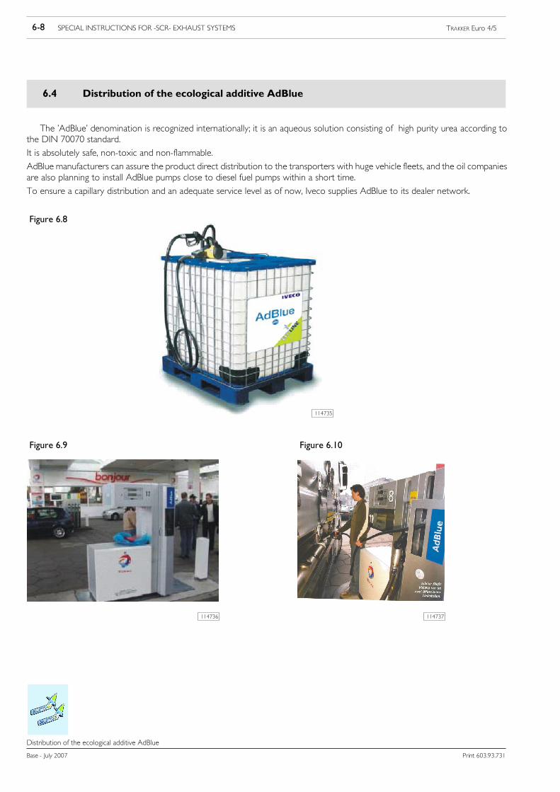
6-8 SPECIAL INSTRUCTIONS FOR -SCR- EXHAUST SYSTEMS TRAKKER Euro 4/5
Base - July 2007 Print 603.93.731
Distribution of the ecological additive AdBlue
Distribution of the ecological additive AdBlue
6.4 Distribution of the ecological additive AdBlue
The ’AdBlue’ denomination is recognized internationally; it is an aqueous solution consisting of high purity urea according tothe DIN 70070 standard.
It is absolutely safe, non-toxic and non-flammable.
AdBlue manufacturers can assure the product direct distribution to the transporters with huge vehicle fleets, and the oil companiesare also planning to install AdBlue pumps close to diesel fuel pumps within a short time.
To ensure a capillary distribution and an adequate service level as of now, Iveco supplies AdBlue to its dealer network.
Figure 6.8
114735
Figure 6.9 Figure 6.10
114737114736

SPECIAL INSTRUCTIONS FOR -SCR- EXHAUST SYSTEMS 6-9TRAKKER Euro 4/5
Print 603.93.731 Base - July 2007
Specifications for installation and removal
Specifications for installation and removal
6.5 Specifications for installation and removal
The instructions that follow are intended for the AdBlue injection system of the Bosch DENOX2 type, within the SCR system.
If Bodybuilders make changes to the frame, the following procedures must be followed under all circumstances:
- disassembly: disconnect the hydraulic connectors first and then the electric connectors;
- assembly: connect the electric connectors first and then the hydraulic connectors.
Compliance with this assembly/disassembly procedure will ensure that AdBlue does not come into contact with the electricconnectors.
6.5.1 Operations for positioning the AdBlue tank
Figure 6.11
116720
As regards the AdBlue tank, ensure that:
- the tank ventilation pipe is never closed;
- the reservoir must contain at least 5 l of AdBlue at the end of each operation to ensure the dosing module is cooled;
- after each operation, the tank does not contain more than 85% of AdBlue (corresponding to the max reading of the level sensor)with respect to the tank total volume, so as to guarantee enough room for AdBlue to expand during freezing at temperaturesbelow -11 °C;
- The urea reservoir must be made out of plastic or stainless steel;
- The reservoir and its float must not be separated.

6-10 SPECIAL INSTRUCTIONS FOR -SCR- EXHAUST SYSTEMS TRAKKER Euro 4/5
Base - July 2007 Print 603.93.731
Specifications for installation and removal
- when fitting equipment onto the chassis, there is enough room for the AdBlue fill gun (1, Figure 6.12) to fit completely andcorrectly into the tank filler.
Figure 6.12
102940
1. Cover - 2. Breather pipe - 3. AdBlue pipe - 4. Engine coolant pipe - 5. Electrical connection - 6. AdBlue pipe -7. Engine cooling pipe - 8. Level gauge
Figure 6.13
116759

SPECIAL INSTRUCTIONS FOR -SCR- EXHAUST SYSTEMS 6-11TRAKKER Euro 4/5
Print 603.93.731 Base - July 2007
Specifications for installation and removal
Figure 6.14
114742
1. H2O infeed/outfeed connectors for AdBlue heater - 2. AdBlue infeed/outfeed connectors
The temperature and level sensors are connected to the DCU (Dosing Control Unit); the level sensor is specific to each type oftank, therefore its dimensions cannot be modified.

6-12 SPECIAL INSTRUCTIONS FOR -SCR- EXHAUST SYSTEMS TRAKKER Euro 4/5
Base - July 2007 Print 603.93.731
Specifications for installation and removal
6.5.2 Operations on AdBlue pipes and heating water
As far as the pipes connecting reservoir, supply module and dosing module are concerned, ensure that:
- the connection pipes between the AdBlue reservoir and the supply module (delivery or inlet line or return or return line) mustbe 5 m long at most and the maximum pressure drop must be 100 hPa under all circumstances;
- the connection pipes between the supply module and the dosing module (delivery or pressure line and return or cooling line)must be 3 m long at most and the maximum pressure drop must be 100 hPa under all circumstances;
The pipes may only be modified using the ”Voss” fittings described in Table 6.13.
Table 6.13 - AdBlue
VOSS/IVECO
Teil -Nr:
Part -No:
Codice:
Benennung Itemname Descrizione Description Descripción
114489
5 4 62 07 00 00
4128 3733EZ 50-7499
Winkelkupplung SV2415/16”Ausführung links;mit MLT 8.8x1.4 PA 0.2Länge 3m und Quetschhülse
ELBOW CONNECTORSV241 5/16” VERSIONLEFT; WITH MLT 8.8x1.4PA0.2 LENGTH 3m ANDCOMPRESSED SLEEVE
RACCORDO ANGOLOSV241 5/16” VERSIONESINISTRA; CON MLT8.8x1.4 PA0.2LUNGHEZZA 3m EBOCCOLA PRESSATA
RACCORD ANGLE SV2415/16” VERSION GAUCHE,AVEC MLT 8.8x1.4 PA0.2LONGUEUR 3 m ETBAGUE PRESSEE
CONEXION EN ANGULOSV241 5/16” VERSIONIZQUIERDA; CON MLT8.8x1.4 PA0.2 LONGITUD3 m Y BOQUILLAPRENSADA
114490
5 4 62 07 56 00
4128 3734EZ 50-7499
Winkelkupplung SV2415/16” Ausführung rechts; mitMLT 8.8x1.4 PA 0.2 Länge3m und Quetschhülse
ELBOW CONNECTORSV241 5/16” VERSIONRIGHT; WITH MLT 8.8x1.4PA0.2 LENGTH 3m ANDCOMPRESSED SLEEVE
RACCORDO ANGOLOSV241 5/16” VERSIONEDESTRA; CON MLT 8.8x1.4PA0.2 LUNGHEZZA 3m EBOCCOLA PRESSATA
RACCORD ANGLE SV2415/16” VERSION DROITE,AVEC MLT 8.8x1.4 PA0.2LONGUEUR 3 m ETBAGUE PRESSEE
CONEXION EN ANGULOSV241 5/16” VERSIONDERECHA; CON MLT8.8x1.4 PA0.2 LONGITUD 3m Y BOQUILLA PRENSADA
114490
5 4 62 08 89 00
4128 3735EZ 50-7499
Geradekupplung SV2415/16”;mit MLT 8.8x1.4 PA 0.2Länge 3mund Quetschhülse
CONNECTOR SV2415/16”; WITH MLT 8.8x1.4PA0.2 LENGTH 3m ANDCOMPRESSED SLEEVE
RACCORDO SV241 5/16”;CON MLT 8.8x1.4 PA0.2LUNGHEZZA 3m EBOCCOLA PRESSATA
RACCORD SV241 5/16”,AVEC MLT 8.8x1.4 PA0.2LONGUEUR 3 m ETBAGUE PRESSEE
CONEXION SV241 5/16”;CON MLT 8.8x1.4 PA0.2LONGITUD 3 m YBOQUILLA PRENSADA
114492
5 4 62 23 26 00
4128 3736EZ 50-7499
Winkelkupplung SV2413/8” Ausführung links;mit MLT 8.8x1.4 PA 0.2Länge 3mund Quetschhülse
ELBOW CONNECTORSV241 3/8” VERSION LEFT;WITH MLT 8.8x1.4 PA0.2LENGTH 3m ANDCOMPRESSED SLEEVE
RACCORDO ANGOLOSV241 3/8” VERSIONESINISTRA; CON MLT8.8x1.4 PA0.2LUNGHEZZA 3m EBOCCOLA PRESSATA
RACCORD ANGLE SV2413/8” VERSION GAUCHE,AVEC MLT 8.8x1.4 PA0.2LONGUEUR 3 m ETBAGUE PRESSEE
CONEXION EN ANGULOSV241 3/8” VERSIONIZQUIERDA; CON MLT8.8x1.4 PA0.2 LONGITUD3 m Y BOQUILLAPRENSADA
114493
5 4 62 23 49 00
4128 3737EZ 50-7499
Winkelkupplung SV2413/8” Ausführung rechts;mit MLT 8.8x1.4 PA 0.2Länge 3mund Quetschhülse
ELBOW CONNECTORSV241 3/8” VERSIONRIGHT; WITH MLT 8.8x1.4PA0.2 LENGTH 3m ANDCOMPRESSED SLEEVE
RACCORDO ANGOLOSV241 3/8” VERSIONEDESTRA; CON MLT 8.8x1.4PA0.2 LUNGHEZZA 3m EBOCCOLA PRESSATA
RACCORD ANGLE SV2413/8” VERSION DROITE,AVEC MLT 8.8x1.4 PA0.2LONGUEUR 3 m ETBAGUE PRESSEE
CONEXION EN ANGULOSV241 3/8” VERSIONDERECHA; CON MLT8.8x1.4 PA0.2 LONGITUD 3m Y BOQUILLA PRENSADA
114494
5 4 62 23 50 00
4128 3738EZ 50-7499
Geradekupplung SV2413/8”;mit MLT 8.8x1.4 PA 0.2Länge 3mund Quetschhülse
CONNECTOR SV241 3/8”;WITH MLT 8.8x1.4 PA0.2LENGTH 3m ANDCOMPRESSED SLEEVE
RACCORDO SV241 3/8”;CON MLT 8.8x1.4 PA0.2LUNGHEZZA 3m EBOCCOLA PRESSATA
RACCORD SV241 3/8”,AVEC MLT 8.8x1.4 PA0.2LONGUEUR 3 m ETBAGUE PRESSEE
CONEXION SV241 3/8”;CON MLT 8.8x1.4 PA0.2LONGITUD 3 m YBOQUILLA PRENSADA
114495
5 4 62 24 70 00
4128 3739EZ 50-7499
Winkelstecker SV246 NG 8Öffnungselement weiss;mit MLT 8.8x1.4 PA 0.2Länge 3mund Quetschhülse
ELBOW CONNECTORSV246 NG 8 RELEASE CLIPWHITE; WITH MLT 8.8x1.4PA0.2 LENGTH 3m ANDCOMPRESSED SLEEVE
RACCORDO ANGOLOSV246 NG 8 ELEMENTODI APERTURA BIANCO;CON MLT 8.8x1.4 PA0.2LUNGHEZZA 3m EBOCCOLA PRESSATA
RACCORD ANGLE SV2418/16” ELEMENTD’OUVERTURE BLANC,AVEC MLT 8.8x1.4 PA0.2LONGUEUR 3 m ETBAGUE PRESSEE
CONEXION EN ANGULOSV246 NG 8 ELEMENTODE APERTURA BLANCO;CON MLT 8.8x1.4 PA0.2LONGITUD 3 m YBOQUILLA PRENSADA
114496
5 4 62 27 60 00
4128 370EZ 50-7499
Winkelstecker SV246 NG 8Öffnungselement schwarz;mit MLT 8.8x1.4 PA 0.2Länge 3mund Quetschhülse
ELBOW CONNECTORSV246 NG 8 RELEASE CLIPBLACK; WITH MLT 8.8x1.4PA0.2 LENGTH 3m ANDCOMPRESSED SLEEVE
RACCORDO ANGOLOSV246 NG 8 ELEMENTODI APERTURA NERO;CON MLT 8.8x1.4 PA0.2LUNGHEZZA 3m EBOCCOLA PRESSATA
RACCORD ANGLE SV2418/16” ELEMENTD’OUVERTURE NOIR,AVEC MLT 8.8x1.4 PA0.2LONGUEUR 3 m ETBAGUE PRESSEE
CONEXION EN ANGULOSV246 NG 8 ELEMENTODE APERTURA NEGRO;CON MLT 8.8x1.4 PA0.2LONGITUD 3 m YBOQUILLA PRENSADA
114497
5 4 66 12 06 49
4128 3741EZ 50-7499
Set Verbinder MLT;1 Verbinder NW62 1-Ohr Schellen1 Montageanleitung
ACHTUNGMontageanleitung9 1 77 00 02 20beachten
SET CONNECTOR MLT;1 CONNECTOR NW62 RETAINING CLIP1 ASSEMBLYINSTRUCTIONATTENTION TAKENOTICE OF ASSEMBLYINSTRUCTION 9 1 77 0002 20
SET DI RACCORDO;1 RACCORDO NW62 FASCETTA1 ISTRUZIONE DIMONTAGGIO PRESTAREATTENZIONE AL’ISTRUZIONE DIMONTAGGIO 9 1 77 0002 20
SET DE RACCORD ;1 RACCORD NVV62 COLLIER1 INSTRUCTION DEMONTAGE RESPECTERLES INSTRUCTIONS DEMONTAGE 9 1 77 00 0220
JUEGO DE CONEXION;1 RACOR NW62 ABRAZADERAS1 INSTRUCCIONES DEMONTAJE PRESTARATENCION A LASINSTRUCCIONES DEMONTAJE 9 1 77 00 02 20
114498
5 4 64 11 16 00
4128 3742EZ 50-7499
RohrMLT 8.8x1.4 PA0.2Länge 10m
TUBE MLT 8.8x1.4 PA0.2LENGTH 10m
TUBO MLT 8.8x1.4 PA0.2LUNGHEZZA 10m
TUBE MLT 8.8x1.4 PA0.2LONGUEUR 10m
TUBO MLT 8.8x1.4 PA0.2LONGITUD 10 m
114500
5 4 62 35 74 00
4128 3743EZ 50-7499
Stecker Trennstelle;mit MLT 8.8x1.4 PA 0.2Länge 3m undQuetschhülse
CONNECTOR SECTIONPOINT; WITH MLT 8.8x1.4PA0.2 LENGTH 3m ANDCOMPRESSED SLEEVE
RACCORDO PIASTRA DISEZIONAMENTO; CONMLT 8.8x1.4 PA0.2LUNGHEZZA 3m EBOCCOLA PRESSATA
RACCORD PLAQUE DESECTIONNEMENT, AVECMLT 8.8x1.4 PA0.2LONGUEUR 3 m ETBAGUE PRESSEE
CONEXION CHAPA DESEPARACION; CON MLT8.8x1.4 PA0.2 LONGITUD3 m Y BOQUILLAPRENSADA
114501
5 4 62 35 75 00
4128 3744EZ 50-7499
KupplungTrennstelle;mit MLT 8.8x1.4 PA 0.2Länge 3m undQuetschhülse
CONNECTOR SECTIONPOINT; WITH MLT 8.8x1.4PA0.2 LENGTH 3m ANDCOMPRESSED SLEEVE
RACCORDO PIASTRA DISEZIONAMENTO; CONMLT 8.8x1.4 PA0.2LUNGHEZZA 3m EBOCCOLA PRESSATA
RACCORD PLAQUE DESECTIONNEMENT, AVECMLT 8.8x1.4 PA0.2LONGUEUR 3 m ETBAGUE PRESSEE
CONEXION CHAPA DESEPARACION; CON MLT8.8x1.4 PA0.2 LONGITUD3 m Y BOQUILLAPRENSADA

SPECIAL INSTRUCTIONS FOR -SCR- EXHAUST SYSTEMS 6-13TRAKKER Euro 4/5
Print 603.93.731 Base - July 2007
Specifications for installation and removal
Table 6.1 - (cont.) Cooling water
VOSS/IVECO
Teil -Nr:
Part -No:
Codice:
Benennung Itemname Descrizione Description Descripción
114502
5 4 62 28 42 00
4128 3745 EZ50-7499
Winkelstecker SV246 NG12 Öffnungselement weiss;mit Rohr Grilamicl 13x1.5Länge 3m
ELBOW CONNECTORSV246 NG 12 RELEASECLIP WHITE; WITHGRILAMID TUBE 13x1.5LENGTH 3m
RACCORDO ANGOLOSV246 NG 12 ELEMENTODI APERTURA BIANCO;CON TUBO GRILAMID13x1.5 LUNGHEZZA 3m
RACCORD ANGLE SV246NG 12 ELEMENTD’OUVERTURE BLANC,AVEC TUBE GRILAMID13x1.5 LONGUEUR 3m
CONEXION EN ANGULOSV246 NG 12 ELEMENTODE APERTURA BLANCO;CON TUBO GRILAMID13x1.5 LONGITUD 3 m
114503
5 4 62 29 49 00
4128 3746 EZ50-7499
Winkelstecker SV246 NG12 Öffnungselement blau;mit Rohr Grilamid 13x1,5Länge 3m
ELBOW CONNECTORSV246 NG 12 RELEASECLIP BLUE; WITH TUBEGRILAMID 13x1.5 LENGTH3m
RACCORDO ANGOLOSV246 NG 12 ELEMENTODI APERTURA BLU; CONTUBO GRILAMID 13x1.5LUNGHEZZA 3m
RACCORD ANGLE SV246NG 12 ELEMENTD’OUVERTURE BLEU,AVEC TUBE GRILAMID13x1.5 LONGUEUR 3m
CONEXION EN ANGULOSV246 NG 12 ELEMENTODE APERTURA AZUL;CON TUBO GRILAMID13x1.5 LONGITUD 3 m
114504
0 0 26 11 50 00
4128 3747 EZ50-7499
Verbinder NW 10 CONNECTOR NW 10 RACCORDO NW 10 RACCORD NW 10 CONEXION NW 10
114505
5 4 64 19 08 00
4128 3748 EZ50-7499
Rohr GRILAMID 13x1.5Länge 10m
TUBE GRILAMID 13x1.5LENGTH 10m
TUBO GRILAMID 13x1.5LUNGHEZZA 10m
TUBE GRILAMID 13x1.5LONGUEUR 10m
TUBO GRILAMID 13x1.5LONGITUD 10 m
114506
5 4 62 35 76 00
4128 3749 EZ50-7499
Stecker Trennstelle; mit RohrGrilamid 13x1,5 Länge 3m
CONNECTOR SECTIONPOINT; WITH TUBEGRILAMID 13x1.5 LENGTH3m
RACCORDO PIASTRA DISEZIONAMENTO; CONTUBO GRILAMID 13x1,5LUNGHEZZA 3m
RACCORD PLAQUE DESECTIONNEMENT AVECTUBE GRILAMID 13x1,5LONGUEUR 3m
CONEXION CHAPA DESEPARACION; CON TUBOGRILAMID 13x1,5LONGITUD 3 m
114507
5 4 62 35 77 00
4128 3750 EZ50-7499
Kupplung Trennstelle; mitRohr Grilamid 13x1,5 Länge3m
CONNECTOR SECTIONPOINT; WITH TUBEGRILAMID 13x1.5 LENGTH3m
RACCORDO PIASTRA DISEZIONAMENTO; CONTUBO GRILAMID 13x1,5LUNGHEZZA 3m
RACCORD PLAQUE DESECTIONNEMENT AVECTUBE GRILAMID 13x1,5LONGUEUR 3m
CONEXION CHAPA DESEPARACION; CON TUBOGRILAMID 13x1,5LONGITUD 3 m
Table 6.1 - (cont.) Corrugated pipe
VOSS/IVECO
Teil -Nr:
Part -No:
Codice:
Benennung Itemname Descrizione Description Descripción
114479
5 4 66 11 37 00
4128 3751 EZ50-7499
Wellrohr NW37 Länge 3mCORRUGATED HOSENW37 LENGTH 3m
TUBO CORRUGATONW37 LUNGHEZZA 3m
TUBE CANNELE NW37LONGUEUR 3m
TUBO CORRUGADONW37 LONGITUD 3 m
114480
5 4 66 12 10 00
4128 3752 EZ50-7499
Wellrohr NW26 Länge 3mCORRUGATED HOSENW26 LENGTH 3m
TUBO CORRUGATONW26 LUNGHEZZA 3m
TUBE CANNELE NW26LONGUEUR 3m
TUBO CORRUGADONW26 LONGITUD 3 m
114481
5 4 66 12 09 00
4128 3753 EZ50-7499
Wellrohr NW22 Länge 3mCORRUGATED HOSENW22 LENGTH 3m
TUBO CORRUGATONW22 LUNGHEZZA 3m
TUBE CANNELE NW22LONGUEUR 3m
TUBO CORRUGADONW22 LONGITUD 3 m
Table 6.1 - (cont.) Breather pipe
VOSS/IVECO
Teil -Nr:
Part -No:
Codice:
Benennung Itemname Descrizione Description Descripción
114511
5 4 66 09 65 00
4128 3757 EZ50-7499
Verbinder NW 6 CONNECTOR NW 6 RACCORDO NW6 RACCORD NW6 CONEXION NW6
114512
5 4 64 19 09 00
4128 3758 EZ50-7499
Rohr 6x1 PA12PHLY Länge10m
TUBE 6x1 PA12PHLYLENGTH 10m
TUBO 6x1 PA12PHLYLUNGHEZZA 10m
TUBE 6x1 PA12PHLYLONGUEUR 10m
TUBO 6x1 PA12PHLYLONGITUD 10 m
114513
5 4 66 10 21 00
4128 3759 EZ50-7499
Verbinder NW 10 CONNECTOR NW 10 RACCORDO NW10 RACCORD NW10 CONEXION NW10
114478
5 4 64 19 10 00
4128 3760 EZ50-7499
Rohr 10x1 PA12PHLYLänge 10m
TUBE 10x1 PA12PHLYLENGTH 10m
TUBO 10x1 PA12PHLYLUNGHEZZA 10m
TUBE 10x1 PA12PHLYLONGUEUR 10m
TUBO 10x1 PA12PHLYLONGITUD 10 m

6-14 SPECIAL INSTRUCTIONS FOR -SCR- EXHAUST SYSTEMS TRAKKER Euro 4/5
Base - July 2007 Print 603.93.731
Specifications for installation and removal
Table 6.1 - (cont.) Tools
VOSS/IVECO
Teil -Nr:
Part -No:
Codice:
Benennung Itemname Descrizione Description Descripción
114482
5 9 94 52 14 00
4128 3770 EZ50-7499
KunststoffrohrMontagezange
NYLON TUBEMOUNTING PLIERS
PINZA DI MONTAGGIOPER TUBO PLASTICA
PINCE DE MONTAGEPOUR TUBE PLASTIQUE
ALICATES DE MONTAJEPARA TUBO DEPLASTICO
5 9 94 71 53 49
4128 3771 EZ50-7499
Spannbacken für Rohr MLT8.8x1.4
CLAMPING JAWS FORTUBE MLT 8.8x1.4
MORSA PER TUBO MLT8.8x1.4
GRIFFE DE SERRAGE POURTUBE MLT 8.8x1.4
MORDAZA PARA TUBOMLT 8.8x1.4
114484
5 9 94 65 41 00
4128 3772 EZ50-7499
Spannbacken für RohrGRILAMID 13x1.5 (08/ 010/012/ 013)
CLAMPING JAWS FORTUBE GRILAMID 13x1.5(08/ 010/ 012/ 013)
MORSA PER TUBOGRILAMID 13x1.5 (08/ 010/012/ 013)
GRIFFE DE SERRAGE POURTUBE GRILAMID 13x1.5(08/ 010/ 012/ 013)
MORDAZA PARA TUBOGRILAMID 13x1.5 (08/ 010/012/ 013)
114485
5 9 94 71 55 00
4128 3773 EZ50-7499
Werkzeugeinsatz Aufnahmefür Verbinder NW6(Harnstoff)
TOOLING INSERT COLLETFOR CONNECTOR NW 6(AD-BLUE)
INSERTO STAMPOALLOGIAMENTO PERCONNETTORI NW6(UREA)
EMPREINTE MOULELOGEMENTCONNECTEURS NVV6(UREE)
UTIL ESTAMPACIONALOJAMIENTO PARACONEXIONES NW6(UREA)
114486
5 9 94 69 16 49
4128 3774 EZ50-7499
Werkzeugeinsatz Aufnahmefür Verbinder NW10(Kühlwasser)
TOOLING INSERT COLLETFOR CONNECTOR NW10 (COOLING WATER)
INSERTO STAMPOALLOGIAMENTO PERCONNETTORI NW10(AQUA DIRAFFREDDAMENTO)
EMPREINTE MOULELOGEMENTCONNECTEURS NW10(EAU DEREFROIDISSEMENT)
UTIL ESTAMPACIONALOJAMIENTO PARACONEXIONES NW10(AGUA DEREFRIGERACION)
114487
5 9 94 71 56 00
4128 3775 EZ50-7499
Aufweitdorn für Rohr MLT8.8x1.4
WIDENING SPIKE FORTUBE MLT 8.8x1.4
MANDRINOALLARGATUBI MLT 8.8x1.4
MANDRIN ADUDGEONNER MLT8.8x1.4
MANDRIL PARAAVELLANAR TUBOS MLT8.8x1.4
9 7 51 00 00 08Klemmzange fürEinohrschelle
CLAMPING PLIERS FORCLIP RETAINER
MORSETTO PERFASCETTA
CLIP POUR COLLIER DESERRAGE
UTIL PARAABRAZADERAS
5 9 94 84 72 00 Kunstoffrohr-Schneidezange NYLON TUBE SCISSORSTRONCHESE PER TUBO INPLASTICA
TRICOISES POUR TUBE ENPLASTIQUE
CORTADOR DE TUBO DEPLASTICO
5 9 94 84 74 00Ersatzklinge fürKunstoffrohr-Schneidezange(2 Stück)
SPARE BLADE FORNYLON TUBE SCISSORS
LAMA DI RICAMBIO PERTRONCHESE PER TUBO INPLASTICA
LAME DE RECHANGE DETRICOISES POUR TUBE ENPLASTIQUE
CUCHILLA DE RECAMBIOPARA CORTADOR DETUBO DE PLASTICO
Table 6.1 - (cont.) Components
VOSS/IVECO
Teil -Nr:
Part -No:
Codice:
Benennung Itemname Descrizione Description Descripción
114477
5 0 99 11 64 00
4128 3761 EZ50-7499
Schutzkappe Tank 0° PROTECTION CAP TANK0°
CAPPA DI PROTEZIONESERBATOIO 0°
CAPUCHON DEPROTECTION RESERVOIR0°
COBERTURA DEPROTECCION DEPOSITO0°
114488
5 0 99 11 71 00
4128 3762 EZ50-7499
Schutzkappe Tank 90° PROTECTION CAP TANK90°
CAPPA DI PROTEZIONESERBATOIO 90°
CAPUCHON DEPROTECTION RESERVOIR90°
COBERTURA DEPROTECCION DEPOSITO90°
114499
5 4 66 09 30 00
4128 3763 EZ50-7499
FaltenbalgCONVOLUTED RUBBERGAITER
SOFFIETTO SOUFFLET RESPIRADERO
114508
5 4 66 09 64 00
4128 3764 EZ50-7499
T-Stück für Wellrohr NW37T-CONNECTOR FORCORRUGATED HOSENW37
DISTRIBUTORE A T PERTUBO CORRUGATONW37
DISTRIBUTEUR EN T POURTUBE ANNELE NW37
DISTRIBUIDOR EN T PARATUBO CORRUGADONW37
114509
5 3 49 03 21 00
4128 3765 EZ50-7499
Deckplatte TrennstelleCOVERPLATE SECTIONPOINT
PIASTRA DI COPERTURAPUNTO DISEZIONAMENTO
PLAQUE DECOUVERTURE POINT DESECTIONNEMENT
CHAPA DE COBERTURAPUNTO DE SEPARACION
114510
5 3 49 03 20 49
4128 3766 EZ50-7499
Grundplatte TrennstelleBASE PLATE SECTIONPOINT
PIASTRA DI BASE PUNTODI SEZIONAMENTO
PLAQUE DE BASE POINTDE SECTIONNEMENT
CHAPA DE BASE PUNTODE SEPARACION
- Whenworking on the pipes, it is compulsory towork in a completely dust-free environment to prevent dust reaching the injector.
- Restore all the pipe insulation (water and Urea pipes) to prevent freezing.

SPECIAL INSTRUCTIONS FOR -SCR- EXHAUST SYSTEMS 6-15TRAKKER Euro 4/5
Print 603.93.731 Base - July 2007
Specifications for installation and removal
6.5.3 Altering the supply module position
If the supply module requires repositioning, scrupulously observe the instructions in Figure 6.15.
The module must be installed horizontally and on a rigid mount.
Figure 6.15
117474
1. AdBlue reservoir - 2. Pumping module - 3. Dosing module - 4. Siphon compulsory
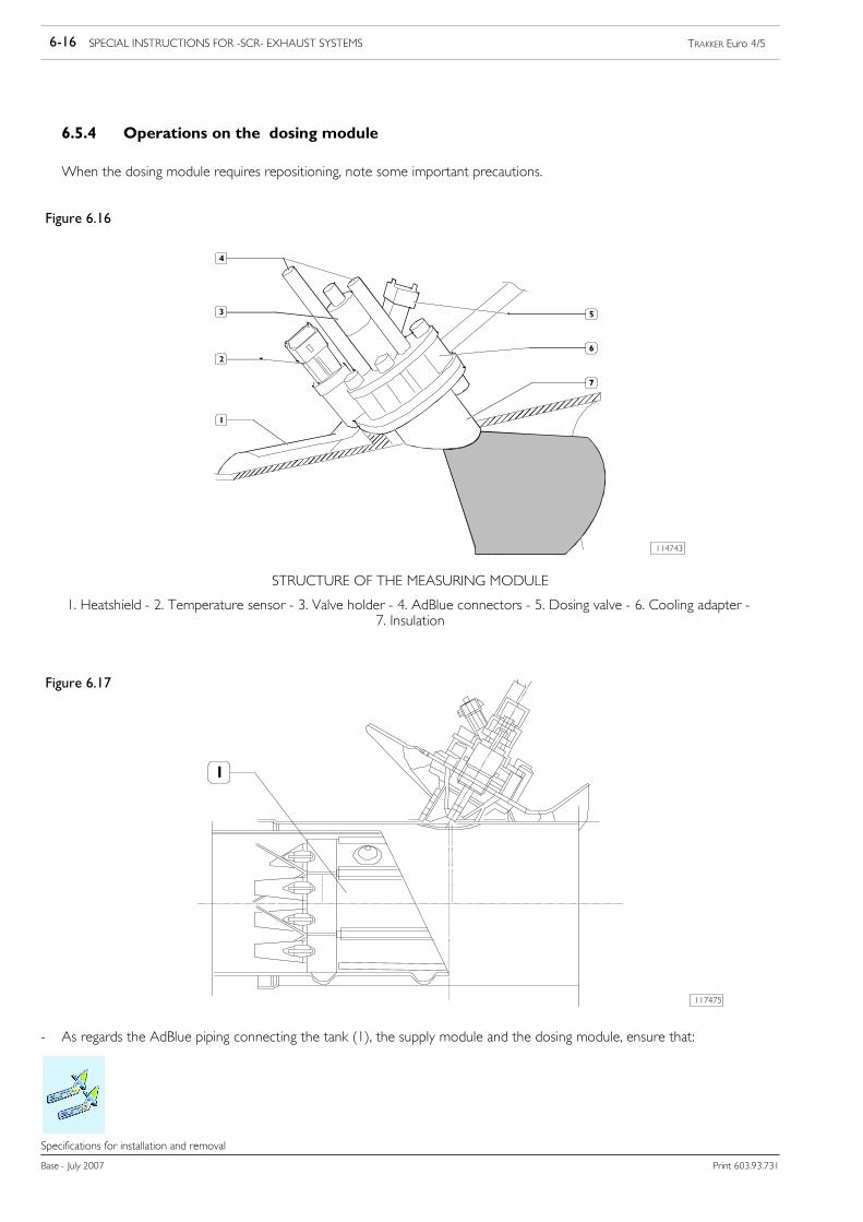
6-16 SPECIAL INSTRUCTIONS FOR -SCR- EXHAUST SYSTEMS TRAKKER Euro 4/5
Base - July 2007 Print 603.93.731
Specifications for installation and removal
6.5.4 Operations on the dosing module
When the dosing module requires repositioning, note some important precautions.
Figure 6.16
114743
STRUCTURE OF THE MEASURING MODULE
1. Heatshield - 2. Temperature sensor - 3. Valve holder - 4. AdBlue connectors - 5. Dosing valve - 6. Cooling adapter -7. Insulation
Figure 6.17
117475
- As regards the AdBlue piping connecting the tank (1), the supply module and the dosing module, ensure that:

SPECIAL INSTRUCTIONS FOR -SCR- EXHAUST SYSTEMS 6-17TRAKKER Euro 4/5
Print 603.93.731 Base - July 2007
Specifications for installation and removal
Figure 6.18
114745
1. Exhaust gas pipe tract involved by the injection of the AdBlue solution - 2. Dosing Module position: -45° / 180° - Exhaustpipe low in at catalyst
The supply module:
- must not be fitted too near to the turbine to prevent it overheating;
- must not be fitted too near the catalytic converter input to prevent the build-up of carbon deposits.
If the dosing module is moved, the pipes and electrical wiring must be modified.NOTE
6.5.5 Operations on exhaust pipes
The exhaust pipe layout cannot be changed without the approval of IVECO.NOTE
The exhaust pipe can be modified paying attention to the following warnings:
- type approved (homologated) counter-pressures must be respectedwhen determining the exhaust pipe route. Form bendswithangles greater than 90˚ and radius of curvature greater than 2.5 times the pipe diameter. Keep the exhaust pipe far enoughaway from rubber or plastic parts and fit heat shields if necessary.
- It is not permitted to use pipes with diameters, thicknesses and materials other than those used for the original equipment.
- It is permitted to use hoses with limited lengths.
Electrical wiring
- It is only possible to lengthen cables for the temperature sensors.
- It is not possible to alter the length of the Nox sensor cable.

6-18 SPECIAL INSTRUCTIONS FOR -SCR- EXHAUST SYSTEMS TRAKKER Euro 4/5
Base - July 2007 Print 603.93.731
Specifications for installation and removal