independent evaluation of medical-grade …...2.2. printing 3d scaffolds a series of 10 mm 10 mm 5...
TRANSCRIPT

polymers
Article
Independent Evaluation of Medical-GradeBioresorbable Filaments for Fused DepositionModelling/Fused Filament Fabrication of TissueEngineered Constructs
Mina Mohseni, Dietmar W. Hutmacher and Nathan J. Castro * ID
Institute of Health and Biomedical Innovation, Queensland University of Technology, Brisbane City 4059,QLD, Australia; [email protected] (M.M.); [email protected] (D.W.H.)* Correspondence: [email protected]; Tel.: +61-7-3138-0055
Received: 9 December 2017; Accepted: 31 December 2017; Published: 2 January 2018
Abstract: Three-dimensional printing/additive manufacturing (3DP/AM) for tissue engineering andregenerative medicine (TE/RM) applications is a multifaceted research area encompassing biology,material science, engineering, and the clinical sciences. Although being quite mature as a researcharea, only a handful of clinical cases have been reported and even fewer commercial productshave made it to the market. The regulatory pathway and costs associated with the introductionof bioresorbable materials for TE/RM have proven difficult to overcome, but greater access to3DP/AM has spurred interest in the processing and availability of existing and new bioresorbablematerials. For this purpose, herein, we introduce a series of medical-grade filaments for fuseddeposition modelling/fused filament fabrication (FDM/FFF) based on established and FederalDrug Administration (FDA)-approved polymers. Manufacturability, mechanical characterization,and accelerated degradation studies have been conducted to evaluate the suitability of eachmaterial for TE/RM applications. The comparative data serves to introduce these materials,as well as a benchmark to evaluate their potential in hard and soft tissue engineering froma physicochemical perspective.
Keywords: tissue engineering and regenerative medicine; bioresorbable polymers; 3D printing/additive manufacturing; fused filament fabrication/fused deposition modelling; degradation;physicochemical characterization
1. Introduction
Three-dimensional printing (3DP) has established itself as a robust and effective technology forthe manufacturing of highly controlled micro- and macro-scale structures that are suitable for use astissue-engineered constructs (TECs). In combination with computer-aided drafting (CAD) and finiteelement modelling (FEM), custom TECs with tunable and pre-designed porous networks providing thenecessary structural support that is required for defect repair and tissue regeneration can be realized.Rapid and precise fabrication of mechanically-analogous three-dimensional (3D) microenvironmentsmake this technique most attractive. Not solely as a tool for controllable 3D architecture, but withthe introduction and availability of high quality and traceable materials, spatiotemporal controlleddelivery of biomolecular agents are feasible when compared to conventional manufacturing methods.Therefore, 3DP is a leading technology in both tissue engineering and drug delivery.
Fused-deposition modelling/fused filament fabrication (FDM/FFF) is one of the most commonand accessible 3DP technologies. FDM/FFF is an additive manufacturing technology that is basedon melt extrusion of thermoplastic polymers with ordered deposition in a layer-by-layer fashion.
Polymers 2018, 10, 40; doi:10.3390/polym10010040 www.mdpi.com/journal/polymers
Polymers 2018, 10, 40 2 of 17
With increasing interest in 3DP as a direct manufacturing technology, global demands for synthetic andnatural materials with 3DP processability is a fast growing and untapped market. Although a plethoraof single material and composite filaments are commercially available, the regulatory qualityassurance/quality controls necessary for implantable 3DP medical devices from thermoplasticprecursor filaments have limited translation to the clinic with few entities in pursuit of this burgeoningmarket. Therefore, the climate is ripe for the introduction of medical-grade 3DP thermoplasticfilaments materials requiring thorough characterization of their potential in tissue engineering andregenerative medicine (TE&RM) applications. Thermoplastic polyesters and polyethers are goodcandidate materials for 3DP, owing to their high tunability with respect to melt properties, a uniqueproperty that is not typically seen in natural polymers where heating results in aloss of bioactivityand structural integrity. A uniform viscose flow and proper cooling rates is associated with themelting temperature, purity, molecular weight, and degree of crystallinity are important factors thatare necessary for high resolution and reproducible printing of FDM/FFF 3D TECs.
TECs should exhibit physicochemical and mechanical properties suitable for initial tissueengraftment and maturation through the modulation of cell behavior, including mechanotransductionduring TEC degradation. Cell-material interactions are complex where mechanical stimuli in the formof local deformation of binding receptors influence intracellular pathways leading to the promotion orinhibition of tissue growth [1,2]. Soft tissues, including adipose tissue, exhibit mechanoresponsivenesswhere adipogenesis is enhanced in the presence of static stretching, but impeded under staticcompression, as well as under dynamic loading [3]. In the case of bone TE&RM, bone depositionand resorption are mutually-exclusive events that are modulated by mechanical stimulation of thetissue [4,5]. According to the minimum effective strains (MES) hypothesis, applied strains greater thanMES causes the adaptation of bone density and architectures, while strain below MES does not produceany change [6]. When considering the clinical application of 3D printed TECs, biomaterial selectionand TEC architecture should be designed to withstand local deformation within the physiologicalrange necessary for tissue deposition. The fundamental characteristics of the bulk material, the overallgeometry of the TEC and the internal geometry synergistically regulate strain distribution on the TECsand, subsequently, the local deformation of microenvironments.
In addition to the structural contributions of 3D printed TECs, physicochemical changes of thestructure, and, ultimately, the material during degradation, is another important aspect when designingTECs for TE&RM. Ideally, the rate of degradation and strength loss should be proportional to therate of tissue growth [7]. As a TEC degrades, a loss in mechanical properties ensues and the rate ofthis action is a necessary consideration when designing TECs that inherently experience high stress.The rate of degradation and subsequent strength loss is an important design parameter for TE&RMresearch. Structural and mechanical integrity should remain during tissue remodelling, especially forlarge volume applications. As previously stated, the function of a scaffold is not only as a mechanicalsupport, but also to serve as a substrate for tissue engraftment and remodelling.
Accelerated degradation of is a widely accepted method to study in vitro physiochemicalchanges of polymers [8]. The degradation rate of synthetic polyester and polyether polymerscan vary from days-to-months, while accelerated degradation provides short-term degradationprofiles, which makes it a time and cost effective method to evaluate and characterize materialsin vitro [9–11]. In vivo degradation of large molecular chains predominantly begins and proceedsby the hydrolysis of amorphous regions and short chains in the polymer backbone, rather thanthrough enzymatic degradation [12]. Utilizing alkaline medium, including sodium hydroxide (NaOH)solutions, which is rich in hydroxyl (–OH) groups, increases hydrolysis and serves as a comparablemethod for in vivo conditions [13].
In the current study, we have extensively characterized four new medical-grade filaments(Dioxaprene® 100 M, Max-Prene® 955, Lactoprene® 100 M, CapropreneTM 100 M kindly donated byPoly-Med, Inc., Anderson, SC, USA) for 3D printability. More importantly, the effects of degradationon physicochemical properties have been evaluated, with special emphasis on mechanical properties.
Polymers 2018, 10, 40 3 of 17
We have assessed these materials for printability via FDM/FFF by optimizing material-specificprinting parameters, as shown in Table 1, as well as undertaken a comprehensive study characterizingphysicochemical changes of 3D printed structures via accelerated degradation in alkaline conditions.Thermal analyses were also conducted to elucidate melt and flow properties for the optimizationof printing temperature. In addition to melt behavior, thermal analysis allows for a betterunderstanding of the morphology of macromolecular chains and re-crystallization of absorbablepolymers. We conclude with a discussion wherein appropriate applications for each group of materialis suggested based on degradation rate and strength loss.
Table 1. Optimized printing parameters.
Material Temperature (◦C) Feed-Rate (mm/min) Layer Height (mm)
DIO 120 1800 0.2CAP 120 1800 0.2LAC 192 1350 0.2MAX 210 1800 0.16
2. Materials and Methods
2.1. Materials
Dioxaprene® 100 M (DIO), CapropreneTM 100 M (CAP), Lactoprene® 100 M (LAC), Max-Prene®
955 (MAX) were kindly donated by Poly-Med, Inc. (Poly-Med, Inc., Anderson, SC, USA). All of thematerials were stored in a low humidity cabinet to minimize moisture absorption. Sodium hydroxide(NaOH, Mw = 40.00, Sigma-Aldrich, St. Louis, MO, USA) solutions of 1 M and 5 M were preparedwith ultrapure water and used in all experiments.
2.2. Printing 3D Scaffolds
A series of 10 mm × 10 mm × 5 mm models were designed in SolidWorks (Dassault Systemes,Waltham, MA, USA) and the resultant computer-aided design (CAD) file was prepared for 3Dprinting by conversion to a computer numerical control file by Simplify3D® (Blue Ash, OH, USA).Next, the models were printed using a FlashForge Dreamer table-top FDM/FFF printer (FlashForge,Jinhua, China) at varying infill densities of: 10%, 20%, and 40%, respectively.
Infill density is a printing parameter that is related to the number of printed fibers comprising theinternal architecture of the printed part. The porosity for each infill density was calculated as the ratioof actual volume to bulk volume using the following formula, where Vb is the bulk volume and Vt isthe true volume.
ρ =Vb − Vt
Vb× 100 (1)
Actual volume was calculated as the mass ratio between the printed scaffold and bulk density ofthe material, as determined by the volume of the rectangular geometry (Table 2).

Polymers 2018, 10, 40 4 of 17
Table 2. The porosity and pore size for three infill densities. Data is represented as mean ± SD (n = 5).
Polymers 2018, 10, 40 4 of 17
Table 2. The porosity and pore size for three infill densities. Data is represented as mean ± SD (𝑛 = 5).
Infill Density (%) Porosity (%) Pore Size (mm)
10 86.9 ± 2.5 2.19 ± 0.05
20 75 ± 4.5 1.01 ± 0.02
40 53.2 ± 3.1 0.37 ± 0.02
2.3. Degradation
Accelerated degradation was conducted for porous scaffolds using NaOH as the hydrolysis
medium. A 1 M NaOH solution was used to study degradation for all four materials. Due to the slow
degradation rate of PCL in 1 M NaOH, a higher concentration (5 M NaOH) was employed. The
samples were immersed into NaOH and incubated at 37 °C, 5% CO2. At each respective time point,
degraded samples were rinsed with deionized water (3×) and dried under vacuum at 40 °C for 8 h.
Mass loss was calculated as the ratio of residual mass (𝑊r) and initial mass (𝑊0), according to the
general formula.
𝑊L% =𝑊0 − 𝑊r
𝑊0% (2)
2.4. Scanning Electron Microscopy
The microstructure of pristine and degraded samples were analysed by scanning electron
microscopy (SEM, JSM-7001F, JEOL Ltd., Tokyo, Japan). For cross-sectional views, samples were
flash frozen in liquid nitrogen (5 min) and cut. All of the samples were gold sputter-coated using a
JEOL fine sputter coater (JFC-1200, JEOL Ltd., Tokyo, Japan) for 75 s at 8 mA current and observed
under vacuum at 2 KV accelerating voltage. Scaffold pore size was determined by measuring 10 fields
of view using ImageJ (National Institutes of Health, Bethesda, MD, USA) [14].
2.5. Thermal Characterization
Melt and thermal properties of pristine and degraded materials were characterized via
differential scanning calorimetry (Q100 DSC, TA Instruments, Newcastle, DE, USA) under non-
isothermal conditions. Additionally, thermal transitions of non-printed monofilaments were
determined to serve as a good estimation of the printing temperature. Samples weighing
approximately 4 mg were sealed in an aluminium pan and exposed to non-isothermal heating at a
ramp rate of 10 °C/min with kinetic analysis performed on the thermographs utilizing universal
analysis 2000 software (TA Instruments, Newcastle, DE, USA).
2.6. Mechanical Testing
Unconfined, uniaxial compression was conducted on pristine and degraded samples using an
Instron Micro Tester (5848, Instron, Melbourne, Australia). In an effort to characterize the effects of
Infill Density (%) Porosity (%) Pore Size (mm)
10 86.9 ± 2.5 2.19 ± 0.0520 75 ± 4.5 1.01 ± 0.0240 53.2 ± 3.1 0.37 ± 0.02
2.3. Degradation
Accelerated degradation was conducted for porous scaffolds using NaOH as the hydrolysismedium. A 1 M NaOH solution was used to study degradation for all four materials. Due to theslow degradation rate of PCL in 1 M NaOH, a higher concentration (5 M NaOH) was employed.The samples were immersed into NaOH and incubated at 37 ◦C, 5% CO2. At each respective timepoint, degraded samples were rinsed with deionized water (3×) and dried under vacuum at 40 ◦C for8 h. Mass loss was calculated as the ratio of residual mass (Wr) and initial mass (W0), according to thegeneral formula.
WL% =W0 − Wr
W0% (2)
2.4. Scanning Electron Microscopy
The microstructure of pristine and degraded samples were analysed by scanning electronmicroscopy (SEM, JSM-7001F, JEOL Ltd., Tokyo, Japan). For cross-sectional views, samples wereflash frozen in liquid nitrogen (5 min) and cut. All of the samples were gold sputter-coated usinga JEOL fine sputter coater (JFC-1200, JEOL Ltd., Tokyo, Japan) for 75 s at 8 mA current and observedunder vacuum at 2 KV accelerating voltage. Scaffold pore size was determined by measuring 10 fieldsof view using ImageJ (National Institutes of Health, Bethesda, MD, USA) [14].
2.5. Thermal Characterization
Melt and thermal properties of pristine and degraded materials were characterized via differentialscanning calorimetry (Q100 DSC, TA Instruments, Newcastle, DE, USA) under non-isothermalconditions. Additionally, thermal transitions of non-printed monofilaments were determined to serveas a good estimation of the printing temperature. Samples weighing approximately 4 mg were sealedin an aluminium pan and exposed to non-isothermal heating at a ramp rate of 10 ◦C/min with kineticanalysis performed on the thermographs utilizing universal analysis 2000 software (TA Instruments,Newcastle, DE, USA).
2.6. Mechanical Testing
Unconfined, uniaxial compression was conducted on pristine and degraded samples usingan Instron Micro Tester (5848, Instron, Melbourne, Australia). In an effort to characterize the effects
Polymers 2018, 10, 40 5 of 17
of material composition and pore size on the mechanical properties, 3D printed TECs with threeporosities were printed and evaluated. To study the effects of degradation on TEC stiffness, mechanicalanalysis was conducted for degraded samples. TECs of 20% infill density were chosen for strengthloss characterization. Briefly, specimens were placed on a flat platen and were compressed at a rateof 0.6 mm/min up to 50% compression (n = 5) in deionized water at 37 ◦C. The elastic modulus wasdefined as the slope of the linear region (Range 4–10%), with the yield strength being defined as thepeak stress of the linear region.
2.7. Contact Angle Analysis
Surface wettability of 3D printed TECs was evaluated by contact angle analysis. Thin films ofthe each polymer was prepared by heating to the respective melting point in an oven and cooled ona 20 mm circular glass cover slip at room temperature. A droplet with the volume of 2 µL was depositedon the films with images that were taken at the static condition using the FTA200 computer-controlled,video based instrument (First Ten Angstroms, Portsmouth, VA, USA). Five positions were randomlytested for each sample.
3. Results
3.1. Degradation
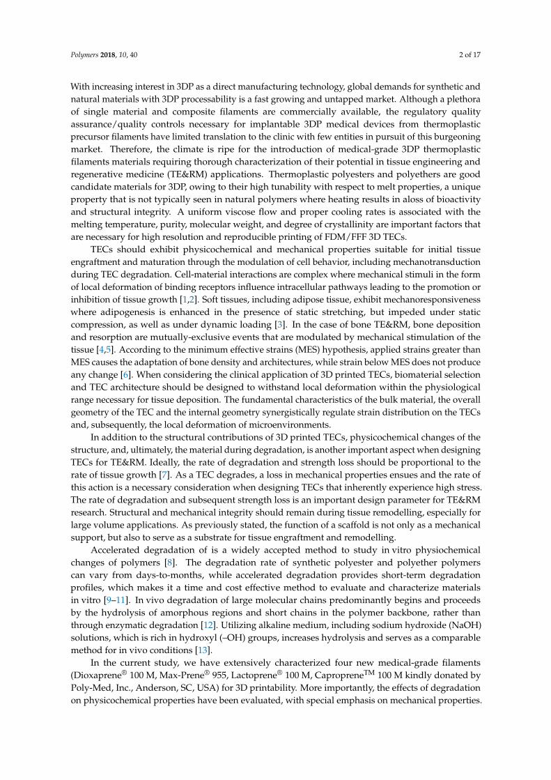
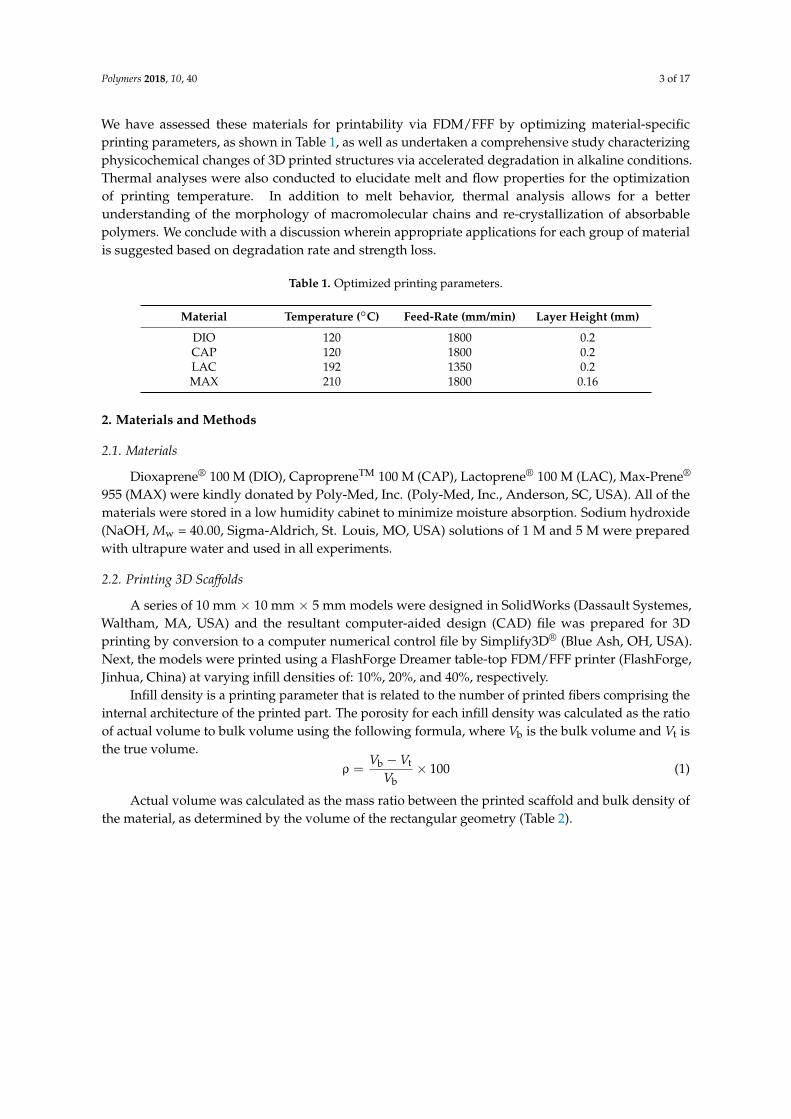
Thermal characterization of pristine, unprinted monofilaments by DSC (Figure 1) was used todetermine the optimal temperature that was necessary for stable viscous flow and printability of themolten polymer. Table 1 shows optimized layer height, printing temperature, and material feed rate.Due to rapid cooling, interlayer fusion of MAX was inadequate at a layer height of 0.2 mm resultingin delamination. Therefore, a layer height of 0.16 mm was used. All of the materials were printedsuccessfully, and SEM images were taken to quantify and validate the pore size of three different infilldensities (Figure 2) with corresponding porosities, as determined using Equation (1).
Although DSC analysis is a good predictor of printing temperature, it is not reflective of theoptimized printing temperature. For instance, PCL does not exhibit viscous flow up to 120 ◦C,while for all other materials, the printing temperature closely matches the melting point. This maybe due to differences in the inherent viscosity and molecular weight of the material at the respectivemelt temperature.
Polymers 2018, 10, 40 5 of 17
material composition and pore size on the mechanical properties, 3D printed TECs with three
porosities were printed and evaluated. To study the effects of degradation on TEC stiffness,
mechanical analysis was conducted for degraded samples. TECs of 20% infill density were chosen
for strength loss characterization. Briefly, specimens were placed on a flat platen and were
compressed at a rate of 0.6 mm/min up to 50% compression (n = 5) in deionized water at 37 °C. The
elastic modulus was defined as the slope of the linear region (Range 4–10%), with the yield strength
being defined as the peak stress of the linear region.
2.7. Contact Angle Analysis
Surface wettability of 3D printed TECs was evaluated by contact angle analysis. Thin films of
the each polymer was prepared by heating to the respective melting point in an oven and cooled on
a 20 mm circular glass cover slip at room temperature. A droplet with the volume of 2 μL was
deposited on the films with images that were taken at the static condition using the FTA200
computer-controlled, video based instrument (First Ten Angstroms, Portsmouth, VA, USA). Five
positions were randomly tested for each sample.
3. Results
3.1. Degradation
Thermal characterization of pristine, unprinted monofilaments by DSC (Figure 1) was used to
determine the optimal temperature that was necessary for stable viscous flow and printability of the
molten polymer. Table 1 shows optimized layer height, printing temperature, and material feed rate.
Due to rapid cooling, interlayer fusion of MAX was inadequate at a layer height of 0.2 mm resulting
in delamination. Therefore, a layer height of 0.16 mm was used. All of the materials were printed
successfully, and SEM images were taken to quantify and validate the pore size of three different
infill densities (Figure 2) with corresponding porosities, as determined using Equation (1).
Although DSC analysis is a good predictor of printing temperature, it is not reflective of the
optimized printing temperature. For instance, PCL does not exhibit viscous flow up to 120 °C, while
for all other materials, the printing temperature closely matches the melting point. This may be due
to differences in the inherent viscosity and molecular weight of the material at the respective melt
temperature.
Figure 1. Non-isothermal DSC trace of non-printed monofilaments at a heating rate of 10 °C/min. Figure 1. Non-isothermal DSC trace of non-printed monofilaments at a heating rate of 10 ◦C/min.
Polymers 2018, 10, 40 6 of 17Polymers 2018, 10, 40 6 of 17
86.9 ± 2.5% 75 ± 4.5% 53.2 ± 3.1%
(a)
×40 ×100 ×200
(b)
Figure 2. Scanning electron microscopy (SEM) micrographs of three-dimensional (3D) printed
scaffolds; (a) Representation of three porosities; (b) Representation of cross-sectional view at varying
magnification.
3.2. Contact Angle Analysis
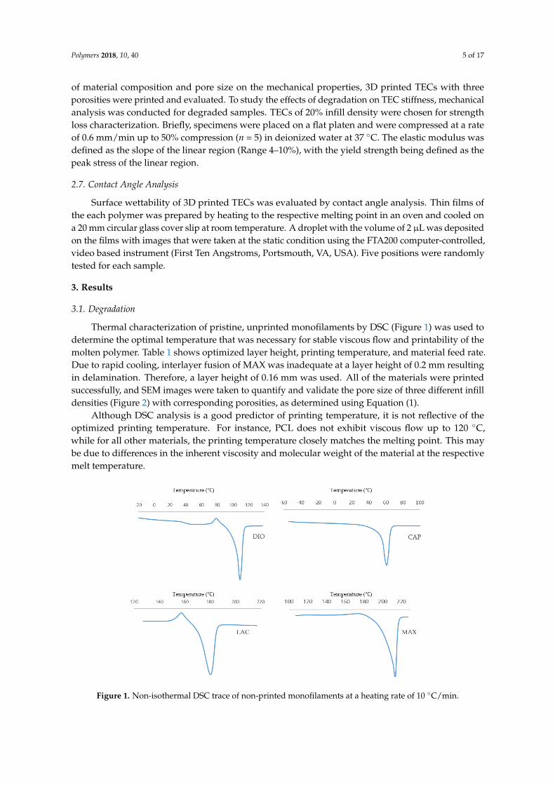
Figure 3 illustrates surface wettability, as determined by contact angle analysis of the four
materials. Results show MAX as the most hydrophilic with a contact angle of 45.8° ± 1.8°, with
increasing hydrophobicity of 58.4° ± 0.42°, 77.8° ± 1°, and 83.2° ± 3.3° for DIO, LAC, and CAP,
respectively.
Figure 3. Water contact angle analysis of polymer films. Data is represented as mean ± SD (𝑛 = 5).
Figure 2. Scanning electron microscopy (SEM) micrographs of three-dimensional (3D) printedscaffolds; (a) Representation of three porosities; (b) Representation of cross-sectional view atvarying magnification.
3.2. Contact Angle Analysis
Figure 3 illustrates surface wettability, as determined by contact angle analysis of the fourmaterials. Results show MAX as the most hydrophilic with a contact angle of 45.8◦ ± 1.8◦,with increasing hydrophobicity of 58.4◦ ± 0.42◦, 77.8◦ ± 1◦, and 83.2◦ ± 3.3◦ for DIO, LAC,and CAP, respectively.
Polymers 2018, 10, 40 6 of 17
86.9 ± 2.5% 75 ± 4.5% 53.2 ± 3.1%
(a)
×40 ×100 ×200
(b)
Figure 2. Scanning electron microscopy (SEM) micrographs of three-dimensional (3D) printed
scaffolds; (a) Representation of three porosities; (b) Representation of cross-sectional view at varying
magnification.
3.2. Contact Angle Analysis
Figure 3 illustrates surface wettability, as determined by contact angle analysis of the four
materials. Results show MAX as the most hydrophilic with a contact angle of 45.8° ± 1.8°, with
increasing hydrophobicity of 58.4° ± 0.42°, 77.8° ± 1°, and 83.2° ± 3.3° for DIO, LAC, and CAP,
respectively.
Figure 3. Water contact angle analysis of polymer films. Data is represented as mean ± SD (𝑛 = 5). Figure 3. Water contact angle analysis of polymer films. Data is represented as mean ± SD (n = 5).
Polymers 2018, 10, 40 7 of 17
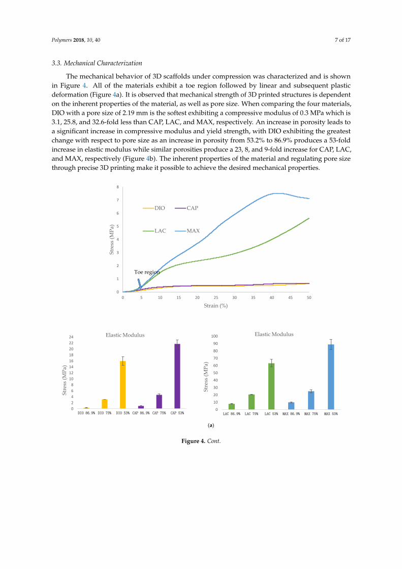
3.3. Mechanical Characterization
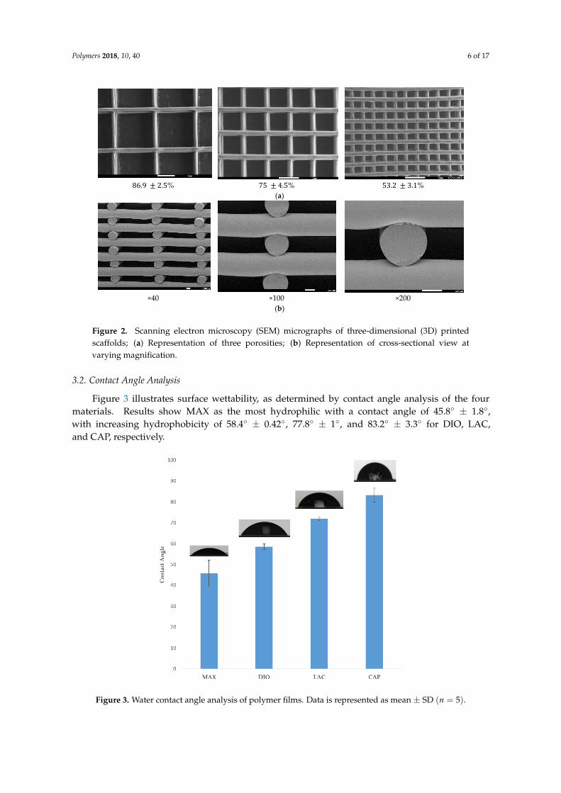
The mechanical behavior of 3D scaffolds under compression was characterized and is shownin Figure 4. All of the materials exhibit a toe region followed by linear and subsequent plasticdeformation (Figure 4a). It is observed that mechanical strength of 3D printed structures is dependenton the inherent properties of the material, as well as pore size. When comparing the four materials,DIO with a pore size of 2.19 mm is the softest exhibiting a compressive modulus of 0.3 MPa which is3.1, 25.8, and 32.6-fold less than CAP, LAC, and MAX, respectively. An increase in porosity leads toa significant increase in compressive modulus and yield strength, with DIO exhibiting the greatestchange with respect to pore size as an increase in porosity from 53.2% to 86.9% produces a 53-foldincrease in elastic modulus while similar porosities produce a 23, 8, and 9-fold increase for CAP, LAC,and MAX, respectively (Figure 4b). The inherent properties of the material and regulating pore sizethrough precise 3D printing make it possible to achieve the desired mechanical properties.Polymers 2018, 10, 40 8 of 17
Polymers 2018, 10, 40; doi:10.3390/polym10010040 www.mdpi.com/journal/polymers
(a)
0
1
2
3
4
5
6
7
8
0 5 10 15 20 25 30 35 40 45 50
Str
ess
(MP
a)
Strain (%)
DIO CAP
LAC MAX
0
2
4
6
8
10
12
14
16
18
20
22
24
DIO 86.9% DIO 75% DIO 53% CAP 86.9% CAP 75% CAP 53%
Str
ess
(MP
a)
Elastic Modulus
0
10
20
30
40
50
60
70
80
90
100
LAC 86.9% LAC 75% LAC 53% MAX 86.9% MAX 75% MAX 53%
Str
ess
(MP
a)
Elastic Modulus
Toe region
Figure 4. Cont.

Polymers 2018, 10, 40 8 of 17
Polymers 2018, 10, 40 9 of 17
(b)
Figure 4. Unconfined, uniaxial compression. (a) Stress-strain curves for the scaffolds with different pore size; (b) Compressive modulus and yield strength for all
materials with three porosities. Data is represented as mean ± SD (𝑛 = 5).
0
0.5
1
1.5
2
2.5
DIO 86.9% DIO 75% DIO 53% CAP 86.9% CAP 75% CAP 53%
Str
ess
(MP
a)
Yield Stress
0
2
4
6
8
10
12
14
LAC 86.9% LAC 75% LAC 53% MAX 86.9% MAX 75% MAX 53%S
tres
s (M
Pa)
Yield Stress
Elastic Modulus (MPa)
Figure 4. Unconfined, uniaxial compression. (a) Stress-strain curves for the scaffolds with differentpore size; (b) Compressive modulus and yield strength for all materials with three porosities. Data isrepresented as mean ± SD (n = 5).
3.4. Degradation
Accelerated degradation was conducted under alkaline conditions to quantify the rate of massloss, strength loss, and to evaluate morphological changes of printed fibers. 1 M NaOH was usedto accelerate hydrolytic degradation of DIO, LAC, and MAX. Since the degradation rate of CAP in1 M NaOH is considerably slower than all of the other materials (Figure 5a, less than 1% after 24 h),5 M NaOH was used to accelerate CAP degradation within a comparable time frame. Hydrolyticdegradation of polymers occurs by erosion of the polymer beginning with cleavage of hydrolytic bondsleading to the formation of water soluble components [15]. All of the materials show non-uniformmass loss under accelerated degradation at the early stages, which is associated with the cleavageof amorphous regions within the polymer. The degradation rate of amorphous regions is typicallyhigher than crystalline regions as the accessibility of water molecules is less energetically costly.Single crystals in close proximity to the degraded amorphous region become unstable leading tocleavage and solubility. As a result, crystalline regions become more accessible and susceptible tohydrolytic cleavage and erosion.
MAX and DIO exhibit the fastest degradation rate, more than 75% mass loss after 2 h, while LACshows less than 10% degradation (Figure 5b). When comparing LAC and CAP, after two days,LAC exhibited >90% mass loss, while CAP exhibited <1% degradation. In 5 M NaOH CAP showsaccelerated degradation leading to ~95% mass loss after 19 days (Figure 5c).

Polymers 2018, 10, 40 9 of 17
Polymers 2018, 10, 40 10 of 17
Polymers 2018, 10, 40; doi:10.3390/polym10010040 www.mdpi.com/journal/polymers
3.4. Degradation
Accelerated degradation was conducted under alkaline conditions to quantify the rate of mass
loss, strength loss, and to evaluate morphological changes of printed fibers. 1 M NaOH was used to
accelerate hydrolytic degradation of DIO, LAC, and MAX. Since the degradation rate of CAP in 1 M
NaOH is considerably slower than all of the other materials (Figure 5a, less than 1% after 24 h), 5 M
NaOH was used to accelerate CAP degradation within a comparable time frame. Hydrolytic
degradation of polymers occurs by erosion of the polymer beginning with cleavage of hydrolytic
bonds leading to the formation of water soluble components [15]. All of the materials show non-
uniform mass loss under accelerated degradation at the early stages, which is associated with the
cleavage of amorphous regions within the polymer. The degradation rate of amorphous regions is
typically higher than crystalline regions as the accessibility of water molecules is less energetically
costly. Single crystals in close proximity to the degraded amorphous region become unstable leading
to cleavage and solubility. As a result, crystalline regions become more accessible and susceptible to
hydrolytic cleavage and erosion.
(a)
(b) (c)
Figure 5. Accelerated degradation; (a,b) Degradation of MAX, DIO, LAC, and PCL in 1 M NaOH. (c)
Degradation of CAP in 5 M NaOH. Data is represented as mean ± SD (𝑛 = 5).
0
10
20
30
40
50
60
70
80
90
100
0 5 10 15 20 25 30 35 40 45 50
Mas
s lo
ss (
%)
Time (hours)
MAX
DIO
LAC
CAP
0
10
20
30
40
50
60
70
80
90
0 1 2 3
Mas
s lo
ss (
%)
Time (hours)
MAX
DIO
LAC
CAP
0
10
20
30
40
50
60
70
80
90
100
0 5 10 15 20
Mas
s lo
ss (
%)
Time (days)
Figure 5. Accelerated degradation; (a,b) Degradation of MAX, DIO, LAC, and PCL in 1 M NaOH.(c) Degradation of CAP in 5 M NaOH. Data is represented as mean ± SD (n = 5).
Morphological studies were conducted via SEM of pristine and eroded samples.Erosion patterning and subsequent morphological changes of the printed structures are directly relatedto water accessibility and surface penetration. SEM images of MAX and LAC show a smooth surfaceat the top and cross section of the printed fibers, which indicates that the speed of water penetrationinto the core of the printed fiber is slower than the speed of hydrolysis of ester bonds. Subsequently,both amorphous and crystalline regions disintegrate prior to diffusion into the subsequent layers.A morphologically smooth surface and uniform decrease of fiber diameter and thickness leads toincreased pore size (Figure 6 (DIO/CAP)). The results are indicative of a predominant surface erosionmechanism of degradation. For MAX, fusion points exhibit a similar erosion pattern with a regularsmooth surface, while for LAC, fusion points have irregular surface morphology, producing a differentmorphological structure when compared to other regions of the 3D printed part. Therefore, the rate ofhydrolysis at the fusion points of LAC is lower than water penetration. This observation indicateshigher and larger crystalline structures that disintegrate in a slower rate when compared to amorphoussites leading voids and non-uniform surfaces. This can be related to the print speed and theoverlaying of molten material wherein the material is cooled at a slower rate allowing for betterrecrystallization. MAX shows a uniform decrease of fusion points with circumferential cracks followedby longitudinal fractures (Figure 6 (LAC/MAX)). When compared to MAX, LAC exhibits a lower

Polymers 2018, 10, 40 10 of 17
density of microfractures on the surface and fusion points, with only a few seen at the fusion points at90% mass loss (Figure 6 (LAC)). CAP displays a roughened surface due to variations in hydrolysisspeed of amorphous and crystalline regions. Crystallites exhibit greater resistance to hydrolysis andare morphologically noted as irregular grains on the surface. Initially, amorphous regions are cleaved,leading to higher crystallite density with more uniform degradation rate. Due to hydrophobic surfacesand high resistance of PCL toward water penetration, degradation proceeds slowly through cleavageof crystallites. The cross sectional view of printed fibers also displays a smooth surface absent of voids,which is indicative of a dominant surface erosion mechanism. Hydrolysis begins at the surface andproceeds very slowly due to high resistance of CAP to water penetration. The erosion pathway of thefusion points and surfaces are morphologically similar. DIO shows large pores on the surfaces andfusion points, which are attributed to fast hydrolysis and increased accessibility of water moleculesinto the interior of polymer. The cross section view shows that degradation begins from the edgescausing non-uniform structures. Since no voids are seen in the core of the printed fiber, the degradationmechanism is predominately surface erosion with the fusion points exhibiting similar morphologicalchanges when compared to other sites.
Strength loss of degraded scaffolds is presented as a factor of mass loss in an effort to evaluate thematerials’ potential for use in applications experiencing moderate to high levels of stress (Figure 7).For all of the samples, strength loss begins with a quick degradation rate followed by a rate decreaseuntil complete disintegration. The rapid initial strength loss can be attributed to the initial attackand scission of amorphous regions by water molecules. This scission produces shortened polymerchains, which can be readily dissolved. At high mass loss, when the density of cracks is increased andthe structure is susceptible to disintegration, the rate of strength loss increases again until completefragmentation. When comparing the rates of mass loss to strength loss, the rate of strength lossexceeds that of mass loss due to the scission of amorphous regions and short chain polymers beforethe complete cleavage of the polymer chains ensues; mass loss appears as the chains are completelybroken and dissolved in water. Before deviations in mass are detectable, strength loss is observed dueto small scissions and cracks. MAX maintains structural and mechanical integrity up to 45% massloss, while LAC preserves mechanical integrity up to 61% mass loss. Although these two polymershave a close mechanical behavior, the rate of strength loss of MAX is faster due to the higher densityof cracks. Developed circumferential cracks at fusion points and longitudinal cracks on the surfacesincrease stress concentration and the risk of failure. DIO shows an integrated structure of up to 30%mass loss, while PCL maintains its’ integrity up to 42% mass loss. DIO is more fragile when comparedto PCL and collapses sooner. As it is observed from SEM analysis, DIO shows large pores at fusionpoints due to faster hydrolysis speed and higher accessibility of water molecules to the interior of DIO.Higher stress concentration at irregular edges and smaller contact area at fusion points make DIOmore fragile.

Polymers 2018, 10, 40 11 of 17
Polymers 2018, 10, 40 12 of 17
to 30% mass loss, while PCL maintains its’ integrity up to 42% mass loss. DIO is more fragile when
compared to PCL and collapses sooner. As it is observed from SEM analysis, DIO shows large pores
at fusion points due to faster hydrolysis speed and higher accessibility of water molecules to the
interior of DIO. Higher stress concentration at irregular edges and smaller contact area at fusion
points make DIO more fragile.
Figure 6. SEM micrographs of degraded samples after losing 30% mass loss at different
magnifications.
𝐃𝐈𝐎
𝐂
𝐀𝐏
𝐌
𝐀𝐗
𝐋
𝐀𝐂
Figure 6. SEM micrographs of degraded samples after losing 30% mass loss at different magnifications.Polymers 2018, 10, 40 13 of 17
Figure 7. Strength loss versus mass loss for degraded scaffolds with porosity of 75%. Data is
represented as mean ± SD (𝑛 = 5).
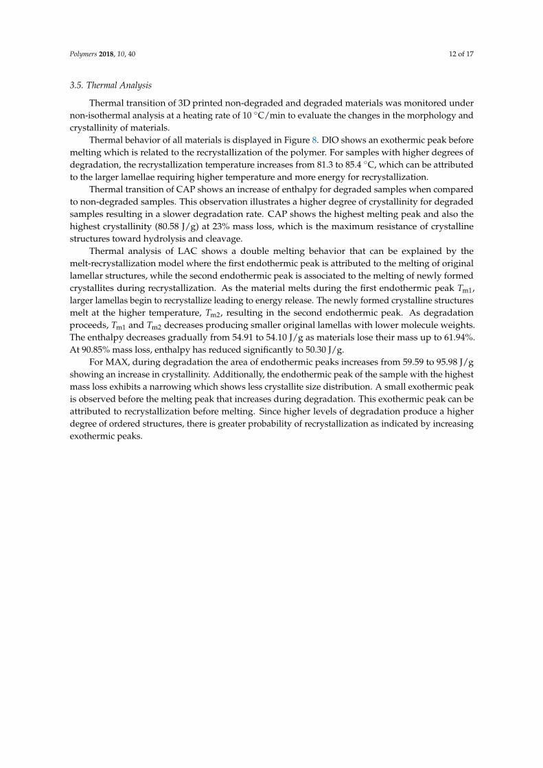
3.5. Thermal Analysis
Thermal transition of 3D printed non-degraded and degraded materials was monitored under
non-isothermal analysis at a heating rate of 10 °C/min to evaluate the changes in the morphology and
crystallinity of materials.
Thermal behavior of all materials is displayed in Figure 8. DIO shows an exothermic peak before
melting which is related to the recrystallization of the polymer. For samples with higher degrees of
degradation, the recrystallization temperature increases from 81.3 to 85.4 °C, which can be attributed
to the larger lamellae requiring higher temperature and more energy for recrystallization.
Thermal transition of CAP shows an increase of enthalpy for degraded samples when compared
to non-degraded samples. This observation illustrates a higher degree of crystallinity for degraded
samples resulting in a slower degradation rate. CAP shows the highest melting peak and also the
highest crystallinity (80.58 J/g) at 23% mass loss, which is the maximum resistance of crystalline
structures toward hydrolysis and cleavage.
Thermal analysis of LAC shows a double melting behavior that can be explained by the melt-
recrystallization model where the first endothermic peak is attributed to the melting of original
lamellar structures, while the second endothermic peak is associated to the melting of newly formed
crystallites during recrystallization. As the material melts during the first endothermic peak 𝑇m1,
larger lamellas begin to recrystallize leading to energy release. The newly formed crystalline
structures melt at the higher temperature, 𝑇m2 , resulting in the second endothermic peak. As
degradation proceeds, 𝑇m1 and 𝑇m2 decreases producing smaller original lamellas with lower
molecule weights. The enthalpy decreases gradually from 54.91 to 54.10 J/g as materials lose their
mass up to 61.94%. At 90.85% mass loss, enthalpy has reduced significantly to 50.30 J/g.
For MAX, during degradation the area of endothermic peaks increases from 59.59 to 95.98 J/g
showing an increase in crystallinity. Additionally, the endothermic peak of the sample with the
highest mass loss exhibits a narrowing which shows less crystallite size distribution. A small
exothermic peak is observed before the melting peak that increases during degradation. This
exothermic peak can be attributed to recrystallization before melting. Since higher levels of
degradation produce a higher degree of ordered structures, there is greater probability of
recrystallization as indicated by increasing exothermic peaks.
0
10
20
30
40
50
60
70
80
90
100
0 10 20 30 40 50 60 70
Str
eng
th L
oss
(%)
mass loss (%)
LAC
DIO
MAC
CAP
Figure 7. Strength loss versus mass loss for degraded scaffolds with porosity of 75%. Data is representedas mean ± SD (n = 5).
Polymers 2018, 10, 40 12 of 17
3.5. Thermal Analysis
Thermal transition of 3D printed non-degraded and degraded materials was monitored undernon-isothermal analysis at a heating rate of 10 ◦C/min to evaluate the changes in the morphology andcrystallinity of materials.
Thermal behavior of all materials is displayed in Figure 8. DIO shows an exothermic peak beforemelting which is related to the recrystallization of the polymer. For samples with higher degrees ofdegradation, the recrystallization temperature increases from 81.3 to 85.4 ◦C, which can be attributedto the larger lamellae requiring higher temperature and more energy for recrystallization.
Thermal transition of CAP shows an increase of enthalpy for degraded samples when comparedto non-degraded samples. This observation illustrates a higher degree of crystallinity for degradedsamples resulting in a slower degradation rate. CAP shows the highest melting peak and also thehighest crystallinity (80.58 J/g) at 23% mass loss, which is the maximum resistance of crystallinestructures toward hydrolysis and cleavage.
Thermal analysis of LAC shows a double melting behavior that can be explained by themelt-recrystallization model where the first endothermic peak is attributed to the melting of originallamellar structures, while the second endothermic peak is associated to the melting of newly formedcrystallites during recrystallization. As the material melts during the first endothermic peak Tm1,larger lamellas begin to recrystallize leading to energy release. The newly formed crystalline structuresmelt at the higher temperature, Tm2, resulting in the second endothermic peak. As degradationproceeds, Tm1 and Tm2 decreases producing smaller original lamellas with lower molecule weights.The enthalpy decreases gradually from 54.91 to 54.10 J/g as materials lose their mass up to 61.94%.At 90.85% mass loss, enthalpy has reduced significantly to 50.30 J/g.
For MAX, during degradation the area of endothermic peaks increases from 59.59 to 95.98 J/gshowing an increase in crystallinity. Additionally, the endothermic peak of the sample with the highestmass loss exhibits a narrowing which shows less crystallite size distribution. A small exothermic peakis observed before the melting peak that increases during degradation. This exothermic peak can beattributed to recrystallization before melting. Since higher levels of degradation produce a higherdegree of ordered structures, there is greater probability of recrystallization as indicated by increasingexothermic peaks.

Polymers 2018, 10, 40 13 of 17Polymers 2018, 10, 40 14 of 17
Figure 8. Thermal characteristics of non-degraded and degraded materials with different mass loss.
Non-isothermal analysis was conducted at heating rate of 10 °C/min using DSC.
4. Discussion
In the current study, we have evaluated four new medical grade filaments for printability,
physicochemical characteristics, and the potential for use in TE&RM applications. Comprehensive
characterization was performed on non-degraded and degraded materials to assess their physical,
mechanical, and morphological properties before and after degradation. These studies provide
greater insight and empirical evidence to support proposed TE&RM applications.
Optimized printing conditions were determined after evaluating the heating effects on phase
transition of monofilaments via DSC (Table 1, Figure 1). The materials were printed successfully with
three different porosities and were assessed under unconfined, uniaxial compression to quantify the
compressive modulus and yield strength. DIO with a pore size of 2.19 mm shows the softest behavior
with an elastic modulus of 300 KPa (Figure 4b). DIO is composed of 100% Polydioxanone (PDO),
which is a synthetic resorbable polymer with high flexibility supported by ether oxygen bonds and
used extensively as an implantable suture. It exhibits excellent biocompatibility, degradability, and
high flexibility, making it appropriate for a variety of biomedical applications. DIO is very sensitive
to internal structures and provides a wide range of mechanical properties by tuning the pore size of
the printed TEC, which makes it highly desirable for TE&RM applications (Figure 4b). This study is
the first reported use of DIO in FFF/FDM 3D printing showing high proccessibility. This potential
along with the inherent soft behavior makes it a good candidate for complex structures in soft tissue
engineering. CAP, which is a copolymer of 95% caprolactone and 5% glycolide, is another
appropriate candidate for soft tissue engineering. When compared to DIO, it shows a higher elastic
modulus, however, as the pore size decreases, the difference is less dramatic. At a pore size of 2.19
mm, elastic modulus of PCL is approximately three times higher than DIO, while at a pore size of
0.37 mm, it is 1.3-fold higher. MAX, a copolymer of 95% glycolide and 5% lactide, shows the highest
elastic modulus, at the pore size of 0.37 mm. Changing pore size from 0.37 to 2.19 mm gives a wide
Figure 8. Thermal characteristics of non-degraded and degraded materials with different mass loss.Non-isothermal analysis was conducted at heating rate of 10 ◦C/min using DSC.
4. Discussion
In the current study, we have evaluated four new medical grade filaments for printability,physicochemical characteristics, and the potential for use in TE&RM applications. Comprehensivecharacterization was performed on non-degraded and degraded materials to assess their physical,mechanical, and morphological properties before and after degradation. These studies provide greaterinsight and empirical evidence to support proposed TE&RM applications.
Optimized printing conditions were determined after evaluating the heating effects on phasetransition of monofilaments via DSC (Table 1, Figure 1). The materials were printed successfullywith three different porosities and were assessed under unconfined, uniaxial compression to quantifythe compressive modulus and yield strength. DIO with a pore size of 2.19 mm shows the softestbehavior with an elastic modulus of 300 KPa (Figure 4b). DIO is composed of 100% Polydioxanone(PDO), which is a synthetic resorbable polymer with high flexibility supported by ether oxygen bondsand used extensively as an implantable suture. It exhibits excellent biocompatibility, degradability,and high flexibility, making it appropriate for a variety of biomedical applications. DIO is verysensitive to internal structures and provides a wide range of mechanical properties by tuning thepore size of the printed TEC, which makes it highly desirable for TE&RM applications (Figure 4b).This study is the first reported use of DIO in FFF/FDM 3D printing showing high proccessibility.This potential along with the inherent soft behavior makes it a good candidate for complex structuresin soft tissue engineering. CAP, which is 100% caprolactone, is another appropriate candidate for softtissue engineering. When compared to DIO, it shows a higher elastic modulus, however, as the poresize decreases, the difference is less dramatic. At a pore size of 2.19 mm, elastic modulus of PCL

Polymers 2018, 10, 40 14 of 17
is approximately three times higher than DIO, while at a pore size of 0.37 mm, it is 1.3-fold higher.MAX, a copolymer of 95% glycolide and 5% lactide, shows the highest elastic modulus, at the poresize of 0.37 mm. Changing pore size from 0.37 to 2.19 mm gives a wide range of properties from9.8 to 88.9 MPa. LAC is 100% Lactide and shows various elastic modulus from 7.79 to 63.17 MPa.By controlling the pore size of MAX and LAC, a wide range of materials properties can be achieved,which are suitable for hard tissue engineering including cartilage and bone tissue.
Accelerated degradation in alkaline medium was conducted to investigate hydrolytic degradationof all the monofilaments. Hydrolysis is a chemical reaction of water molecules with polymersthat produces carboxylic acid, followed by cleavage of -OH bonds, resulting in the erosion ofpolymer matrix [16]. In this study, mass loss rate was evaluated in NaOH and depicted in Figure 5.By comparison of these results with contact angle analysis, it is realized that more hydrophilic surfacesshows higher degradation speed (Figure 3). SEM analysis shows surface erosion for four materials asthe predominant degradation pathway. Figure 6 illustrates that degradation begins from the edgeswith no voids being seen radially towards the core. However, surface morphology of each polymer isdifferent due to various rates of hydrolysis and water penetration into the polymer fibre with DIOexhibiting large voids on the surfaces. Hydrophilic surfaces for DIO, as well as fast hydrolysis, resultsin decreased stability and porosity. PCL exhibits a roughened surface due to the presence of highlywater-resistant crystallites. MAX and LAC show smooth surfaces and uniform edges, with MAXexhibiting a high density of cracks at the fusion points and fibre surface leading to decreased mechanicalstability and greater water accessibility.
In designing TECs, the bulk properties of materials as well as their degradation behavior andphysicochemical changes should be considered. The inherent properties of materials and the internalstructures of scaffolds, including pore size, are predominant factors in controlling the mechanicalproperties of designed TECs. Depending on tissue morphology and the cascade of biologicalphenomena during the regenerative process, an “optimized” pore size can vary. Feng. B showedthat pore size <400 µm limits the growth and infiltration of blood vessels in a porous bioceramicscaffolds [17]. JP. Temple studied osteogenesis and angiogenesis of large craniomaxillofacial bonedefects, with TEC exhibiting pore sizes of 0.1–2 mm [18]. The results show that uniform distribution ofhuman adipose-derived stem cells with high density of vascular network was obtained at a pore size of~800 µm. For larger pore sizes, cell aggregation ensues, leading to sedimentation and decreased activity,whereas for the smaller pore sizes, cell aggregation is minimized. In contrast to large bone defects, forbarrier membrane in dental applications, smaller pores (<200 µm) is suggested to control the growthand infiltration of epithelial and gingival fibroblasts at early stages [19]. By decreasing the rate ofcellular infiltration at early time points, bone tissue has more space to mature and remodel over time.Infection is one of the major concerns for applications involving barrier membranes. By employingTECs with small pore sizes, the risk of infection can be minimized [19]. By considering the limitationof pore size in a specific application, materials and internal structures should be chosen carefully toensure suitable conditions for growth of tissue.
Based on the current study, MAX and LAC may be suitable candidates for musculoskeletaltissue engineering. These materials exhibit excellent printing fidelity allowing for the manufacture ofcomplex geometries for large and small defects. By controlling pore size, a wide range of propertiescan be achieved. In addition, by printing composite structures of MAX and LAC, the unique propertiesof each material can be combined with predefined geometries leading to a higher degree of controlon mechanical properties as well as degradation rate. Depending on the volume of defects and thespeed of regeneration, the degradability of composite structures can be tuned. MAX degrades within36 h in alkaline solution, while LAC exhibits 90% mass loss after 48 h. A composite structure ofthese two materials with different degradation rates is also feasible and merits further investigation inparticular for drug delivery applications, where the release profile of drugs can be controlled by fasterdegrading material and the structure of scaffolds can be preserved by long-term degradable materials.As previously stated, infection is one of the major concerns with implantable TECs, which can be

Polymers 2018, 10, 40 15 of 17
addressed by controlled release of antimicrobial drugs within the first few days of implantationwhen macrophages show the highest activity [20]. Utilizing dual extruding printers and controllingthe number of layers and internal structures of each material shows great promise for controlledmechanical properties, degradation, and drug release.
With regards to soft tissue engineering, most available printing materials are natural hydrogels,which cannot be readily printed in complex geometries, especially for large volume tissueregeneration [21]. In this study, DIO has been introduced as a soft polymer with high flexibilityalong with high 3D printing fidelity for complex small and large structures. When compared to CAP,DIO exhibits a faster degradation rate, which makes it more appropriate for short-term regenerativeapplications. DIO may also be an appropriate polymer matrix for artificial skin patches owing to itsmechanical and physicochemical properties. Additionally, skin does not require extended degradationfor long-term regeneration and remodelling, which makes DIO a better candidate when comparedto CAP or other materials. Degradation of PCL, which is the main component of CAP, is very slow(>2 years) [9,22], and a combination of DIO and CAP may provide the added capability of adjustingthe degradation rate of TECs to be temporally compatible with tissue regeneration and remodelling.In addition to dual extrusion FDM/FFF printing, these polymers can be mixed during printing asthey have similar printing temperature. The potential addition of DIO into the TEC allows for greatertunability with regards to degradation rate and mechanical properties. Recently, the concept ofharnessing the body as a “bioreactor” has been investigated by our group and coupled with delayedfat injection [23] has shown promising results for large volumes. Delaying the administration of fatinto the TEC leverages the initial cascade of biological events leading to fibrous tissue infiltration andneovascularization. By controlling the degradation rate of the internal TEC architecture, adequatespace post-implantation can be modulated allowing for more uniform tissue ingrowth. One potentialembodiment would utilize DIO as the internal structure, while providing the mechanical behavior thatis necessary to ensure tissue viability by using PCL as a slow degradable polymer. Another importantpositive aspect of composite structures is in drug delivery where the degradation rate directlyaffects the release rate of incorporated drugs. The hydrophobic surface of CAP, as well as its slowdegradation, limits sustained delivery. In most therapeutic/regenerative applications, the speedof tissue regeneration is slow, while drug delivery is required for a short period post-implantation.Therefore, for combinatorial TECs, including antibacterial embodiments, antimicrobial agents needto be released at the early stages of regeneration. Releasing antibiotics within the first weeks prior tocomplete formation of blood clot can decrease the risk of infection considerably. Therefore, employingDIO as a delivery system in soft tissue engineering is suggested.
5. Conclusions
The current study served to introduce a family of 3D printable bioresorbable medical-gradematerials for use in TE/RM applications. With the combination of material traceability and accessiblehigh-resolution 3D printing technologies, we may find ourselves at the forefront of commercially-viable3DP/AM for TE/RM applications.
Acknowledgments: The authors would like to thank Poly-Med, Inc. for kindly supplying all materials used inthe current study.
Author Contributions: Dietmar W. Hutmacher and Nathan J. Castro conceived and designed the experiments;Mina Mohseni performed the experiments; Mina Mohseni and Nathan J. Castro analyzed the data; Mina Mohseniwrote the paper.
Conflicts of Interest: The authors declare no conflict of interest.

Polymers 2018, 10, 40 16 of 17
References
1. Qin, Y.-X.; Lam, H. Intramedullary pressure and matrix strain induced by oscillatory skeletal musclestimulation and its potential in adaptation. J. Biomech. 2009, 42, 140–145. [CrossRef] [PubMed]
2. Damaraju, S.; Matyas, J.R.; Rancourt, D.E.; Duncan, N.A. The effect of mechanical stimulation onmineralization in differentiating osteoblasts in collagen-I scaffolds. Tissue Eng. Part A 2014, 20, 3142–3153.[CrossRef] [PubMed]
3. Yuan, Y.; Gao, J.; Ogawa, R. Mechanobiology and Mechanotherapy of Adipose Tissue-Effect of MechanicalForce on Fat Tissue Engineering. Plast. Reconstr. Surg. Glob. Open 2015, 3, e578. [CrossRef] [PubMed]
4. Frost, H.M. Bone “mass” and the “mechanostat”: A proposal. Anat. Rec. 1987, 219, 1–9. [CrossRef] [PubMed]5. Frost, H.M. The mechanostat: A proposed pathogenic mechanism of osteoporoses and the bone mass effects
of mechanical and nonmechanical agents. Bone Miner. 1987, 2, 73–85. [PubMed]6. Frost, H. A determinant of bone architecture: The minimum effective strain. Clin. Orthop. Relat. Res. 1983,
175, 286–292. [CrossRef]7. Ikada, Y. Challenges in tissue engineering. J. R. Soc. Interface 2006, 3, 589–601. [CrossRef] [PubMed]8. Ginjupalli, K.; Shavi, G.V.; Averineni, R.K.; Bhat, M.; Udupa, N.; Upadhya, P.N. Poly(α-hydroxy acid)
based polymers: A review on material and degradation aspects. Polym. Degrad. Stab. 2017, 144, 520–535.[CrossRef]
9. Sun, H.; Mei, L.; Song, C.; Cui, X.; Wang, P. The in vivo degradation, absorption and excretion of PCL-basedimplant. Biomaterials 2006, 27, 1735–1740. [CrossRef] [PubMed]
10. Felfel, R.; Poocza, L.; Gimeno-Fabra, M.; Milde, T.; Hildebrand, G.; Ahmed, I.; Scotchford, C.; Sottile, V.;Grant, D.M.; Liefeith, K. In vitro degradation and mechanical properties of PLA-PCL copolymer unit cellscaffolds generated by two-photon polymerization. Biomed. Mater. 2016, 11, 015011. [CrossRef] [PubMed]
11. Lam, C.X.; Savalani, M.M.; Teoh, S.H.; Hutmacher, D.W. Dynamics of in vitro polymer degradation ofpolycaprolactone-based scaffolds: Accelerated versus simulated physiological conditions. Biomed. Mater.2008, 3, 034108. [CrossRef] [PubMed]
12. Therin, M.; Christel, P.; Li, S.; Garreau, H.; Vert, M. In vivo degradation of massive poly (α-hydroxy acids):Validation of in vitro findings. Biomaterials 1992, 13, 594–600. [CrossRef]
13. Htay, A.; Teoh, S.; Hutmacher, D. Development of perforated microthin poly (ε-caprolactone) films asmatrices for membrane tissue engineering. J. Biomater. Sci. Polym. Ed. 2004, 15, 683–700. [CrossRef][PubMed]
14. Schneider, C.A.; Rasband, W.S.; Eliceiri, K.W. NIH Image to ImageJ: 25 years of image analysis. Nat. Meth.2012, 9, 671–675. [CrossRef]
15. Göpferich, A. Mechanisms of polymer degradation and erosion. Biomaterials 1996, 17, 103–114. [CrossRef]16. Li, S. Hydrolytic degradation characteristics of aliphatic polyesters derived from lactic and glycolic acids.
J. Biomed. Mater. Res. 1999, 48, 342–353. [CrossRef]17. Feng, B.; Jinkang, Z.; Zhen, W.; Jianxi, L.; Jiang, C.; Jian, L.; Guolin, M.; Xin, D. The effect of pore size on tissue
ingrowth and neovascularization in porous bioceramics of controlled architecture in vivo. Biomed. Mater.2011, 6, 015007. [CrossRef] [PubMed]
18. Temple, J.P.; Hutton, D.L.; Hung, B.P.; Huri, P.Y.; Cook, C.A.; Kondragunta, R.; Jia, X.; Grayson, W.L.Engineering anatomically shaped vascularized bone grafts with hASCs and 3D-printed PCL scaffolds.J. Biomed. Mater. Res. Part A 2014, 102, 4317–4325. [CrossRef] [PubMed]
19. Rakhmatia, Y.D.; Ayukawa, Y.; Furuhashi, A.; Koyano, K. Current barrier membranes: Titanium mesh andother membranes for guided bone regeneration in dental applications. J. Prosthodont. Res. 2013, 57, 3–14.[CrossRef] [PubMed]
20. Johnson, C.T.; García, A.J. Scaffold-based anti-infection strategies in bone repair. Ann. Biomed. Eng. 2015, 43,515–528. [CrossRef] [PubMed]

Polymers 2018, 10, 40 17 of 17
21. Hinton, T.J.; Jallerat, Q.; Palchesko, R.N.; Park, J.H.; Grodzicki, M.S.; Shue, H.-J.; Ramadan, M.H.;Hudson, A.R.; Feinberg, A.W. Three-dimensional printing of complex biological structures by freeformreversible embedding of suspended hydrogels. Sci. Adv. 2015, 1, e1500758. [CrossRef] [PubMed]
22. Lam, C.X.; Hutmacher, D.W.; Schantz, J.T.; Woodruff, M.A.; Teoh, S.H. Evaluation of polycaprolactonescaffold degradation for 6 months in vitro and in vivo. J. Biomed. Mater. Res. Part A 2009, 90, 906–919.[CrossRef] [PubMed]
23. Chhaya, M.P.; Balmayor, E.R.; Hutmacher, D.W.; Schantz, J.-T. Transformation of breast reconstruction viaadditive biomanufacturing. Sci. Rep. 2016, 6, 28030. [CrossRef] [PubMed]
© 2018 by the authors. Licensee MDPI, Basel, Switzerland. This article is an open accessarticle distributed under the terms and conditions of the Creative Commons Attribution(CC BY) license (http://creativecommons.org/licenses/by/4.0/).