indentation creep studies of iron aluminide intermetallic alloy
TRANSCRIPT

Indentation creep studies of iron aluminide intermetallic alloy
Garima Sharmaa,*, R.V. Ramanujanb, T.R.G. Kuttyc, N. Prabhud
aMaterials Science Division, BARC, Mumbai, IndiabSchool of Materials Engineering, Nanyang Technological University, Singapore
cRadiometallurgy Division, BARC, Mumbai, India4Indian Institute of Technology, Mumbai, India
Received 17 March 2004; received in revised form 10 May 2004; accepted 17 May 2004
Available online 17 July 2004
Abstract
Indentation creep behaviour of iron aluminide intermetallic (Fe–28Al–3Cr) was studied in the temperature range of 843–963 K. The
hardness and the plasticity parameter were also calculated from room temperature to 1273 K. The variation of hardness with time showed that
the stress exponent ðnÞ was weakly dependent on temperature. Thermal activation parameter-activation area and energy were also calculated
to identify the creep mechanism. The activation energy for high temperature creep was found to be in good agreement with that for self-
diffusion of pure iron and in excellent agreement with previous studies. These values of n, activation area and activation energy were found to
be consistent with dislocation climb as the rate controlling creep mechanism. Conventional creep curves were also derived from hardness
values.
q 2004 Elsevier Ltd. All rights reserved.
Keywords: A. Iron aluminides (based on Fe3Al); B. Creep (properties and mechanisms); B. Mechanical properties at high temperatures
1. Introduction
The indentation creep test provides a simple and non-
destructive method of investigating the mechanical proper-
ties of solids, it also gives information about the time
dependent flow of materials [1–4]. In this test, the indenter
is maintained at a constant load over a period of time under
well-controlled conditions. As the stresses cause the
material beneath the indenter to creep, the indenter
penetrates and changes in the indentation size are
monitored. Thus, indentation creep is the time dependent
motion of a hard indenter into a solid under constant load
[5,6]. An important advantage of the indentation creep
technique is that all the creep information can be collected
from the same sample, which not only greatly reduces the
effort for sample preparation but also reduces the sample to
sample variation in property [7]. This technique can be used
for studying the creep properties of high temperature
materials such as intermetallics and ceramics, including
diamond, which are very difficult to evaluate using
conventional methods. Thus, indentation method can be
regarded as a quick and non-destructive procedure to extract
information on the mechanical behaviour of materials
[6–8].
Iron aluminides based on B2 or DO3 ordered Fe3Al based
alloys are now receiving extensive attention as materials
with good potential for industrial applications as replace-
ment for high temperature oxidation resisting or corrosion
resisting stainless steel [9–11]. The lack of ductility at room
temperature and a decrease in strength above 873 K had
retarded their development as a structural material.
However, improvement in the room temperature ductility
of Fe3Al has been achieved recently by the addition of
alloying elements such as Cr [11,12]. Efforts are continuing
to develop iron aluminides with improved high temperature
tensile and creep-properties. Much effort has been paid to
structure control in order to optimize the mechanical
properties of Fe3Al based alloys. In general, the alloys
show various types of creep behaviour, which depends
on condition such as stress, temperature, grain size and
alloy composition [9–24]. The aim of the present paper is to
study the creep properties of this alloy by the indentation
creep method.
0966-9795/$ - see front matter q 2004 Elsevier Ltd. All rights reserved.
doi:10.1016/j.intermet.2004.05.008
Intermetallics 13 (2005) 47–53
www.elsevier.com/locate/intermet
* Corresponding author. Tel.: þ91-22-5505-151; fax: þ91-22-1559-
0457.
E-mail address: [email protected] (G. Sharma).
1.1. Sargent and Ashby’s model of indentation creep
In this model, Sargent and Ashby [25] have suggested
that the stress and strain fields in a material below the
pyramidal indenter are self similar in time and creep
deformation is found to follow the power law of the type
_e ¼ A0sn exp2Q
RT
� �ð1Þ
where _e is the steady state strain rate, A0 is a constant, s is
the applied stress, n is the stress exponent, Q is the
activation energy and R is the universal gas constant
The displacement rate of an indentor in the underlying
material has been derived as
du
dt¼
_e0ðffiffiA
pÞ
C2
!P
A
C1
s0
� �n
ð2Þ
where A is the projected area of indentation, C2 is a constant
and _e0 is the strain rate at a reference stress s0: For a pyra-
midal indentor the penetration is proportional toffiffiA
p; i.e.,
u ¼ C3ðffiffiA
pÞ ð3Þ
Differentiating Eq. (3) with respect to time and substituting
into Eq. (2),
dA
dt¼ C4 _e0A
P
As0
� �n
ð4Þ
where C3 and C4 are constants. Substituting hardness
ðHÞ ¼ P=A where P is the normal load and A is area of
penetration, Sargent and Ashby [25] have derived the
following relationship between indentation hardness and
dwell time:
HðtÞ ¼s0
ðnC4 _e0tÞ1=nð5Þ
where HðtÞ is the time dependent hardness. From Eq. (4),
when P is held constant, we get
1
H
� �dH
dt
� �¼ 2C4 _e0
H
s0
� �n
ð6Þ
Hence, from Eq. (5) the gradient of a plot of lnðHÞ against
lnðtÞ at a constant temperature is 21=n: Also a plot of lnðHÞ
versus ln½ð21=HÞðdH=dtÞ� at a constant temperature has a
slope n (from Eq. (6)). The activation energy is calculated
from the plot of lnðtÞ against 1=T at constant hardness, the
slope of which provides Q=R:
2. Experimental procedure
The nominal alloy composition used in this study was
Fe–28Al–3Cr (at%). Samples were prepared by air
induction melting followed by electro-slag re-melting,
using high purity elements. The microstructure of the
alloy consists of equiaxed grains with an average grain size
of 414 mm. The hot hardness measurements were carried
out using a Nikon hot hardness tester (Nikon, Model QM)
equipped with diamond Vickers micro-hardness indenter.
Before starting the hot hardness experiments, the instrument
was calibrated using standard samples (Cu: SRM; National
Bureau of Standards, USA). Five indentations were made on
the standard using 0.2 kg load. The hardness obtained was
found to be ^0.5% of the actual value. Samples of
5 mm £ 5 mm were cut from the alloy and metallographi-
cally prepared. The sample was loaded into the furnace of
the hot hardness tester and evacuated to 0.1 Pa. The
hardness was measured from room temperature to 1000 8C
at 100 8C intervals with a dwell time of 5 s. All
measurements were taken in the central region of the
sample. At each temperature, at least four indentations were
taken.
The indentation creep measurements were carried out
using a load of 0.2 kg at 843, 873, 903, 933 and 963 K. This
choice of temperature was based on the known softening
behaviour of this class of alloys. At each temperature, the
hardness was measured as a function of dwell time. The
dwell times used in this study were 5, 15, 30, 100 and 300 s.
For each dwell time, at least four indentations were taken.
The indentation creep was also measured in the central
region of the sample and all indentations were away from
the edges.
3. Results
The variation of hardness ðHÞ with temperature ðTÞ of
Fe–28Al–3Cr alloy is given in Table 1. H –T data of the
above mentioned alloy has been analysed in detail and
results are reported elsewhere [26]. The indentation creep
was studied by plotting a graph between hardness and dwell
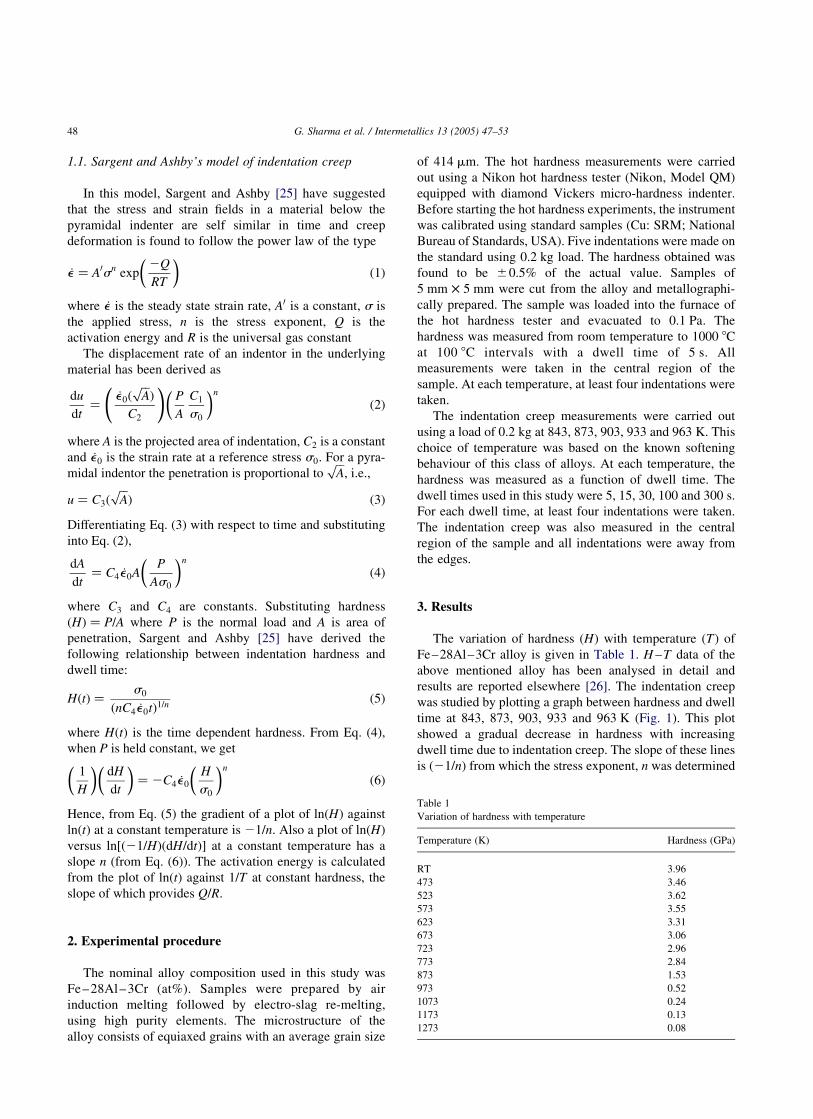
time at 843, 873, 903, 933 and 963 K (Fig. 1). This plot
showed a gradual decrease in hardness with increasing
dwell time due to indentation creep. The slope of these lines
is ð21=nÞ from which the stress exponent, n was determined
Table 1
Variation of hardness with temperature
Temperature (K) Hardness (GPa)
RT 3.96
473 3.46
523 3.62
573 3.55
623 3.31
673 3.06
723 2.96
773 2.84
873 1.53
973 0.52
1073 0.24
1173 0.13
1273 0.08
G. Sharma et al. / Intermetallics 13 (2005) 47–5348
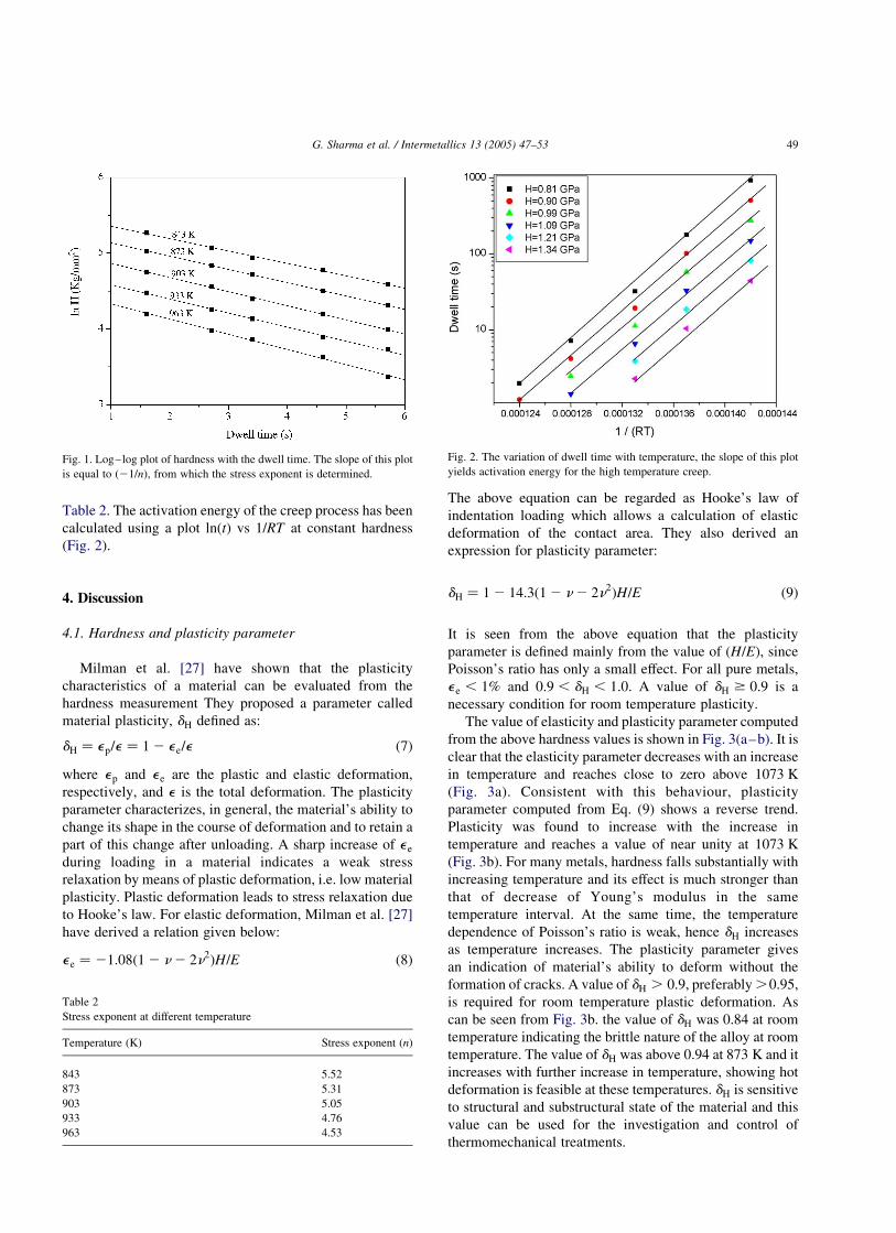
Table 2. The activation energy of the creep process has been
calculated using a plot lnðtÞ vs 1=RT at constant hardness
(Fig. 2).
4. Discussion
4.1. Hardness and plasticity parameter
Milman et al. [27] have shown that the plasticity
characteristics of a material can be evaluated from the
hardness measurement They proposed a parameter called
material plasticity, dH defined as:
dH ¼ ep=e ¼ 1 2 ee=e ð7Þ
where ep and ee are the plastic and elastic deformation,
respectively, and e is the total deformation. The plasticity
parameter characterizes, in general, the material’s ability to
change its shape in the course of deformation and to retain a
part of this change after unloading. A sharp increase of ee
during loading in a material indicates a weak stress
relaxation by means of plastic deformation, i.e. low material
plasticity. Plastic deformation leads to stress relaxation due
to Hooke’s law. For elastic deformation, Milman et al. [27]
have derived a relation given below:
ee ¼ 21:08ð1 2 n2 2n2ÞH=E ð8Þ
The above equation can be regarded as Hooke’s law of
indentation loading which allows a calculation of elastic
deformation of the contact area. They also derived an
expression for plasticity parameter:
dH ¼ 1 2 14:3ð1 2 n2 2n2ÞH=E ð9Þ
It is seen from the above equation that the plasticity
parameter is defined mainly from the value of ðH=EÞ; since
Poisson’s ratio has only a small effect. For all pure metals,
ee , 1% and 0:9 , dH , 1:0: A value of dH $ 0:9 is a
necessary condition for room temperature plasticity.
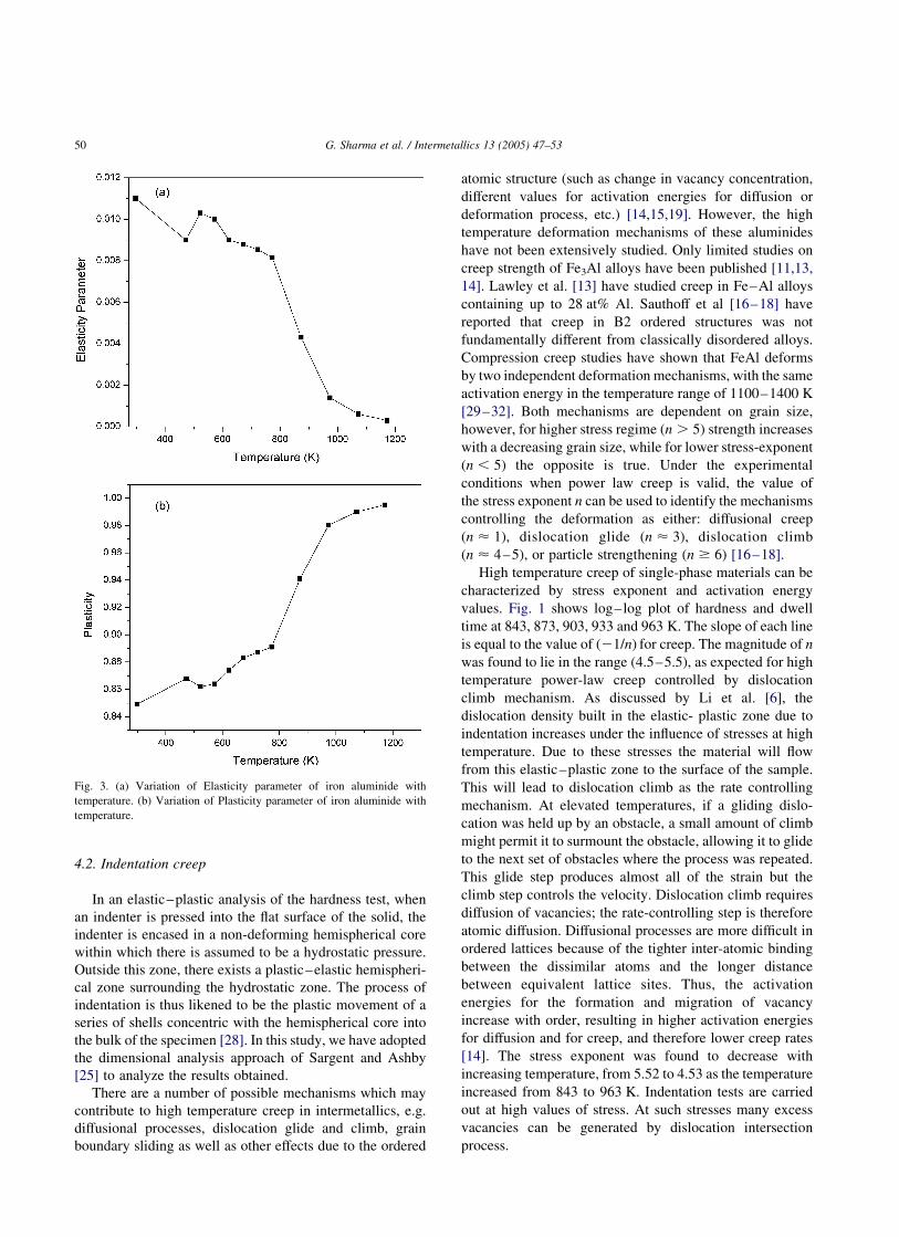
The value of elasticity and plasticity parameter computed
from the above hardness values is shown in Fig. 3(a–b). It is
clear that the elasticity parameter decreases with an increase
in temperature and reaches close to zero above 1073 K
(Fig. 3a). Consistent with this behaviour, plasticity
parameter computed from Eq. (9) shows a reverse trend.
Plasticity was found to increase with the increase in
temperature and reaches a value of near unity at 1073 K
(Fig. 3b). For many metals, hardness falls substantially with
increasing temperature and its effect is much stronger than
that of decrease of Young’s modulus in the same
temperature interval. At the same time, the temperature
dependence of Poisson’s ratio is weak, hence dH increases
as temperature increases. The plasticity parameter gives
an indication of material’s ability to deform without the
formation of cracks. A value of dH . 0:9; preferably .0.95,
is required for room temperature plastic deformation. As
can be seen from Fig. 3b. the value of dH was 0.84 at room
temperature indicating the brittle nature of the alloy at room
temperature. The value of dH was above 0.94 at 873 K and it
increases with further increase in temperature, showing hot
deformation is feasible at these temperatures. dH is sensitive
to structural and substructural state of the material and this
value can be used for the investigation and control of
thermomechanical treatments.
Fig. 1. Log–log plot of hardness with the dwell time. The slope of this plot
is equal to ð21=nÞ; from which the stress exponent is determined.
Table 2
Stress exponent at different temperature
Temperature (K) Stress exponent ðnÞ
843 5.52
873 5.31
903 5.05
933 4.76
963 4.53
Fig. 2. The variation of dwell time with temperature, the slope of this plot
yields activation energy for the high temperature creep.
G. Sharma et al. / Intermetallics 13 (2005) 47–53 49
4.2. Indentation creep
In an elastic–plastic analysis of the hardness test, when
an indenter is pressed into the flat surface of the solid, the
indenter is encased in a non-deforming hemispherical core
within which there is assumed to be a hydrostatic pressure.
Outside this zone, there exists a plastic–elastic hemispheri-
cal zone surrounding the hydrostatic zone. The process of
indentation is thus likened to be the plastic movement of a
series of shells concentric with the hemispherical core into
the bulk of the specimen [28]. In this study, we have adopted
the dimensional analysis approach of Sargent and Ashby
[25] to analyze the results obtained.
There are a number of possible mechanisms which may
contribute to high temperature creep in intermetallics, e.g.
diffusional processes, dislocation glide and climb, grain
boundary sliding as well as other effects due to the ordered
atomic structure (such as change in vacancy concentration,
different values for activation energies for diffusion or
deformation process, etc.) [14,15,19]. However, the high
temperature deformation mechanisms of these aluminides
have not been extensively studied. Only limited studies on
creep strength of Fe3Al alloys have been published [11,13,
14]. Lawley et al. [13] have studied creep in Fe–Al alloys
containing up to 28 at% Al. Sauthoff et al [16–18] have
reported that creep in B2 ordered structures was not
fundamentally different from classically disordered alloys.
Compression creep studies have shown that FeAl deforms
by two independent deformation mechanisms, with the same
activation energy in the temperature range of 1100–1400 K
[29–32]. Both mechanisms are dependent on grain size,
however, for higher stress regime ðn . 5Þ strength increases
with a decreasing grain size, while for lower stress-exponent
ðn , 5Þ the opposite is true. Under the experimental
conditions when power law creep is valid, the value of
the stress exponent n can be used to identify the mechanisms
controlling the deformation as either: diffusional creep
ðn < 1Þ; dislocation glide ðn < 3Þ; dislocation climb
ðn < 4–5Þ; or particle strengthening ðn $ 6Þ [16–18].
High temperature creep of single-phase materials can be
characterized by stress exponent and activation energy
values. Fig. 1 shows log–log plot of hardness and dwell
time at 843, 873, 903, 933 and 963 K. The slope of each line
is equal to the value of ð21=nÞ for creep. The magnitude of n
was found to lie in the range (4.5–5.5), as expected for high
temperature power-law creep controlled by dislocation
climb mechanism. As discussed by Li et al. [6], the
dislocation density built in the elastic- plastic zone due to
indentation increases under the influence of stresses at high
temperature. Due to these stresses the material will flow
from this elastic–plastic zone to the surface of the sample.
This will lead to dislocation climb as the rate controlling
mechanism. At elevated temperatures, if a gliding dislo-
cation was held up by an obstacle, a small amount of climb
might permit it to surmount the obstacle, allowing it to glide
to the next set of obstacles where the process was repeated.
This glide step produces almost all of the strain but the
climb step controls the velocity. Dislocation climb requires
diffusion of vacancies; the rate-controlling step is therefore
atomic diffusion. Diffusional processes are more difficult in
ordered lattices because of the tighter inter-atomic binding
between the dissimilar atoms and the longer distance
between equivalent lattice sites. Thus, the activation
energies for the formation and migration of vacancy
increase with order, resulting in higher activation energies
for diffusion and for creep, and therefore lower creep rates
[14]. The stress exponent was found to decrease with
increasing temperature, from 5.52 to 4.53 as the temperature
increased from 843 to 963 K. Indentation tests are carried
out at high values of stress. At such stresses many excess
vacancies can be generated by dislocation intersection
process.
Fig. 3. (a) Variation of Elasticity parameter of iron aluminide with
temperature. (b) Variation of Plasticity parameter of iron aluminide with
temperature.
G. Sharma et al. / Intermetallics 13 (2005) 47–5350

4.2.1. Thermal activation parameters
Two important thermal activation parameters often used
for the identification of the operating creep mechanism are
the activation energy and the activation area The activation
area can be defined as:
Ap ¼kT
b
� �d ln _1
dss
� �ð10Þ
where Ap is the activation area and _1 is the creep rate (in
general the deformation rate), k is the Boltzmann constant
and b is the Burgers vector. In the indentation creep testing,
it is not possible to directly evaluate the deformation partial
d ln _1=dss: However, if a conventional creep curve could be
derived from the hardness time plots (hardness versus
time curves), the deformation partial in Eq. (10) can be
estimated. The models developed by Mulhearn et al. [33]
assumes that the indentation produces an average represen-
tative strain given by:
1 ¼ A0ðd=DÞb0
ð11Þ
where d and D are the diameters of the indentation and the
indentor, respectively, and A0 and b0 are constants, the value
of b0 is suggested to be 1.
A similar model proposed by Atkins [34] suggests that b0
should be 1.5. If D is kept constant, the above Eq. (11)
would show that 1/ d and since H / d22; substituting H in
place of d for constant load, one can arrive at
1/ 1=ffiffiffiH
pð12Þ
Similarly, for Atkins model one can arrive at
1/ 1=ðHÞ1:5 ð13Þ
The conventional creep curve can be derived by plotting
ð1=HÞ1:5 as a function of time. However, in the literature it
has been shown that converting the hardness time
relationship into conventional creep curves and then
estimating the activation energy using Atkin’s model were
in better agreement with the values of activation energy
calculated from the conventional creep data. Typical
conventional creep curves derived from the Atkin’s model
are shown in Fig. 4. Here the strain is equated to ð1=HÞ1:5 and
therefore is in arbitrary units. In this curve, a near steady
state seems to have been attained after 100 s. For small
times the creep strain is almost primary in nature.
Indentation tests are high stress test. The stress generated
during the indentation process is estimated to be greater than
E=1000 where E is the Young’s modulus. Since the stresses
are higher in the indentation tests, the onset of secondary
creep is expected to be faster. Kutty et al. [35] have
transformed the hardness time plots into conventional creep
for various alloys like stainless steel AISI 316 and zircaloy
2. From the resultant creep curves, the activation energy for
creep computed was found to be comparable with those in
the reported in the literature.
The activation area is computed in the following manner:
Two creep strain values are selected along a creep curve
(constant temperature) and the corresponding creep rates are
computed, from the slope of the creep curve. The hardness
values corresponding to the two selected strain values are
known and hence the stress values can be computed (from
the applied load and the projected area of indentation). The
quantity D ln _1=Dss is then calculated and substituted in
Eq. (10) to yield the activation area. The computed value of
activation area was found to be 1.74 b2 which is
representative and have to be considered as only order of
magnitude estimates.
In a similar way the activation energy for creep can also
be computed from the derived creep curves. The relevant
expression used for this computation is:
Q ¼ R½lnðt1=t2Þ�=ð1=T1 2 1=T2Þ ð14Þ
where t1 and t2 are the time to reach a given strain (i.e. a
given hardness) value at two temperatures T1 and T2: A
constant hardness means a constant area of indentation and
since load was kept constant, the situation corresponds to a
constant stress, thus validating the procedure employed for
calculating Q (Fig. 2). These experimental results showed
that the activation energy for high temperature creep lies in
the range of 339–341 kJ/mol. McKamey [14] has reported
creep activation energy of 334–355 kJ/mol in the same
temperature range, which is in excellent agreement with
the experimental results of the present study. An activation
energy value of 355 kJ/mol has also been reported in the
temperature range of 843–963 K [13], which also com-
pares favourably with the present results. Chen et al. [20]
reported that, at 873 K, Fe3Al alloys exhibit dislocation
creep as rate controlling creep mechanism which further
supports the results of this paper. Similar values
of activation energy of plastic flow were obtained in
Fig. 4. Conventional creep curve for iron aluminide derived from hardness
values.
G. Sharma et al. / Intermetallics 13 (2005) 47–53 51

Ref. [36] for FeAl based alloy. However, a recent review
by Jordon et al. [37] showed that the activation energy of
iron aluminides lies in the range of 250–300 kJ/mol.
Malek et al. [38] have reported an activation energy of
280 kJ/mol for high temperature deformation of Fe3Al
based alloys. They have also reported stress exponent
values in the range of 4–5 which are in good agreement
with the present study. Activation energy obtained in the
present study is slightly higher than those reported in
Ref. [37]. As suggested by Sherby and Burke [39] the
effect of temperature on elastic modulus should be taken
into account when calculating the activation energy for
creep. The present study did not make the above
corrections for the modulus while calculating activation
energy. This could be one of the reasons why the
calculated value of activation energy for creep was slightly
higher than that for self-diffusion. Since self-diffusion
depends on vacancy interchange with atoms, the activation
energy is the sum of the formation and migration of
vacancies. Agreement between the values of the activation
energies of creep and self-diffusion of pure iron suggests
that dislocation climb is the rate controlling mechanism.
Several mechanisms have been proposed in the literature
to account for the creep rate observed at high temperatures.
Mechanisms based on diffusional flow such as Herring-
Nabarro creep and Coble creep can be straight away
discounted since these models require n to be unity or nearly
so. The observed values of n are much higher and lies in the
range of 4.5–5.5. Two mechanisms have been mainly
referred to in the literature which predict n values in the
experimental range of 4–7 [40,41]. These are (i) the model
of climb of edge dislocation (ii) the model of jogged screw
dislocation motion. While the expected activation energy
for creep is the same for the two mechanisms (namely
activation energy for self diffusion), they are distinguishable
on the basis of the activation area. The climb model requires
Ap to be about b2 while that for non-conservative motion of
jogs is a few hundred b2: The experimental activation area
was close to 1.74 b2; which shows that dislocation climb
was the rate controlling mechanism. Based on the values of
n; Ap and Q obtained in the present study it is concluded that
dislocation climb was the high temperature creep
mechanism.
5. Conclusions
The indentation creep behaviour in the temperature range
of 843 963 K of a Fe–28Al–3Cr was evaluated in this
study. The results showed that the stress exponent varied
between 4.5 and 5.5 with temperature. These values of stress
exponent lie in the range expected for high temperature
power-law creep controlled by dislocation climb mechan-
ism. The value of activation energy for creep was found to
be comparable to the activation energy for the self-diffusion
of pure iron, also indicating that dislocation climb was
the rate controlling mechanism. Further, the activation area
calculated was also showed consistent with dislocation
creep as the rate controlling mechanism. Thus, it can
concluded that the Fe–28Al–3Cr undergoes creep by
dislocation climb mechanism.
Acknowledgements
The authors would like to thank Dr P.K. De, Head,
Materials Science Division and Dr S. Banerjee, Director,
Materials Group, for their encouragement. The authors
would also like to thank Mr K. Ravi, Radiometallurgy
Division for his help.
References
[1] Westbrook JH. Trans Am Soc Met 1953;45:221.
[2] Atkins AG. Met Sci 1982;16:127.
[3] Underwood EE. Mater Meth 1957;45:127.
[4] Geach GA. Int Met Rev 1974;19:255.
[5] Li WB, Warren R. Acta Metall Mater 1993;41:3065.
[6] Li WB, Henshall JL, Hooper RM, Easterling KE. Acta Metall Mater
1991;39:3099.
[7] Chiang D, Li JCM. J Metal Res 1994;9:903.
[8] Okada A, Yamamolo Y, Yoda R. J Iron Steel Inst Japan 1987;73:
1186.
[9] McKamey CG, Liu CT. Scripta Metall Mater 1990;24:2119.
[10] McKamey CG, Horton JA, Liu CT. High temp ordered intermetallic
alloys II. In: Stoloff NS, Koch CC, Liu CT, Izumi O, editors. Materials
Research Society Proceedings, vol. 81.; 1987. p. 321.
[11] McKamey CG, Devan JH, Tortorelli PF, Sikka VK. J Mater Res 1991;
6:1779.
[12] Sikka VK. Ductility enhancement of iron aluminide alloy. SAMPE Q
1991;7:2.
[13] Lawley A, Coll JA, Cahn RW. TMS AMIE 1960;218:166.
[14] McKamey CG, Maziasz PJ, Jones JW. J Mater Res 1992;7:2089.
[15] Garofalo CF. Fundamentals of creep and creep rupture in metals. New
York: The Macmillan Co; 1965.
[16] Rudy M, Sauthoff G. Mater Sci Engng 1986;81:525.
[17] Rudy M, Sauthoff G. In: Koch CC, Liu CT, Stoloff NS, editors. High
temperature ordered intermetallic alloys. Materials Research Society
Symposium Proceedings, vol. 39.; 1985. p. 327. Pittsburgh, PA.
[18] Jung I, Rudy M, Sauthoff G. In: Koch CC, Liu CT, Stoloff NS, Izumi
O, editors. High temperature ordered intermetallic alloy II. Materials
Research Society Symposium Proceedings, vol. 81.; 1987. p. 263.
Pittsburgh, PA.
[19] Sherby OD, Burke PM. Prog Mater Sci 1968;13:325.
[20] Chen G, Huang Y, Yang W, Sun Z. In: Schneibel JH, Crimp MA,
editors. Processing, properties and applications of iron aluminides.
The minerals, metals and materials society; 1994. p. 131.
[21] Dakshinamurthy VK, Baligidad RG. Mater Sci Engng 2002;A328:
58–61.
[22] Deevi SC. Swindeman. Mater Sci Engng, A 1998;258:203–10.
[23] Sundar RS, Sastry DH. Intermetallics 2000;8:1061–5.
[24] Mckamey CG, Maziasz PJ. Intermetallics 1998;6:303–14.
[25] Sargent PM, Ashby MF. Mater Sci Technol 1992;8:594.
[26] Sharma G, Ramanujan RV, Kutty TRG, Tiwari GP. Mater Sci Engng
2000;A278:106–12.
[27] Milman YuV, Galanov BA, Chugunova SI. Acta Metall Mater 1993;
41:2523.
[28] Johnson KL. J Mech Phys Solids 1970;18:115.
G. Sharma et al. / Intermetallics 13 (2005) 47–5352

[29] Whittenberger JD. Mater Sci Engng 1983;57:77.
[30] Whittenberger JD. Mater Sci Engng 1986;77:103.
[31] Vedula K, Stephens JR. Mater Res Soc Symp Proc 1987;81:381.
[32] Titran RH, Vedula K, Anderson G. Mater Res Soc Symp Proc 1985;
39:319.
[33] Mulhearn TO, Tabor D. J Inst Met 1960–1961;89:7.
[34] Atkins AG. In: Westbrook JH, Conard H, editors. The science of
hardness testing and its research applications. Metal Park, OH: ASM;
1971. p. 223.
[35] Kutty TRG, Ganguly C, Sastry DH. Scripta Mater 1996;34(12):1833.
[36] Krupa M. Intermetallics 2004;12:295–302.
[37] Jordon JL, Deevi SC. Intermetallics 2003;11:507–28.
[38] Malek P, Kretochvil P, Pesicka J, Hanus P, Sediva I. Intermetallics
2002;10:985–92.
[39] Sherby OD, Burke PM. Mechanical behaviour of crystalline solids at
elevated temperatures. New York: Pergamon Press; 1968.
[40] Weertman J. J Appl Phys 1955;26:1213.
[41] Weertman J. J Appl Phys 1957;28:362.
G. Sharma et al. / Intermetallics 13 (2005) 47–53 53