increasing void fraction of the polypropylene foams blown with chemical … · ·...
TRANSCRIPT

Increasing Void Fraction of the Polypropylene Foams Blown
with Chemical Blowing Agents in High Temperature
Extrusion
By
K.M. Zamil Andalib
A thesis submitted in conformity with the requirements
For the degree of Master of Applied Science
Department of Mechanical and Industrial Engineering
University of Toronto
© Copyright by K.M. Zamil Andalib 2015

II
Increasing Void Fraction of the Polypropylene Foams Blown with
Chemical Blowing Agents in High Temperature Extrusion
K.M. Zamil Andalib
Master of Applied Science
Department of Mechanical and Industrial Engineering
University of Toronto
2015
ABSTRACT
The global demand for the polymeric foams especially Polypropylene (PP) foams is increasing
rapidly. Some industrial processing of the PP foam need high processing temperature. But, there
are only a few research has been done on high temperature processing as the quality of foam
deteriorates in that condition. Moreover, Physical Blowing Agents (PBA) need additional
accessories to process the foam. But usually industries are reluctant to change their existing system
to get foamed output initially. This thesis develops an approach to manufacture PP foams with
Chemical Blowing Agents (CBA) in high temperature extrusion. In the first step, a series of
fundamental studies have been carried out by investigating the effect of different chemical blowing
agent and content, pressure drop rate and residence time on the foaming behavior of polypropylene.
And then, optimized parameters are applied and the combination effect of CBA-PBA and the effect
of nucleating agents has been examined.

III
To my beloved wife, Prova
For all the sacrifices, love and support during my journey to
MASc degree.
IV
ACKNOWLEDGMENT
Words are not good enough for the acknowledgment to those people who helped me through my
academic life in University of Toronto. Without their generosity and encouragement my journey
toward M.A.Sc. Degree would never be successful.
First of all I would like to thank Prof. Chul B. Park from the bottom of my heart for his valued
supervision, personal guidance and encouragement throughout my research in the Microcellular
Plastics Manufacturing Laboratory. I have learned so much from him throughout these two years
which is integral for my growth as a mechanical engineer, and will be a solid foundation for my
future career.
I would like to thank my M.A.Sc. Oral Exam committee, Professor Kamran Behdinan and
Professor Lidan You, for their valuable feedback in my M.A.Sc. oral examination.
My gratitude is also extended to the Department of Mechanical and Industrial Engineering and the
School of Graduate Studies at the University of Toronto. I would also like to thank AUTO21 for
providing me with funding and opportunities to expand my research and professional networks.
I would also like to take this opportunity to acknowledge the support from my previous and current
colleagues of MPML. Their friendships are integral parts of my graduate studies experience. My
research works would not have been as successful without their advice and assistance, especially
Dr. Raymond Chu. I also want thank Kara Kim for her kind assistance. My special thanks goes
out to Dr. Changwei Zhu, Dr. Saleh Amani, Dr. Amir Ameli, Dr. Davoud Jahani, Dr. Nemat
Hossieny, Dr. Ali Rizvi, Dr. Adel Ramezani Kakroodi, Dr. Minh-Phuong Tran, Dr. Pengjian Gong,
V
Dr. Guilong Wang, Dr. Long Wang, Lun Howe Mark, Weidan Ding, Sasan Rezaei, Palaniappan
Arumugam, Hasan Mahmood, Mohammed Alshrah, Seongsoo Bae, Yasamin Kazemi, Alireza
Tabatabaei, Mehdi Saniei, Vahid Shaayegan, Piyapong Buahom, Junghyub Lee, Chongxiang
Zhao, Pavani Cherukupally, Sai Wang as well as everyone else who helped me during my M.A.Sc.
studies.
I also want give a special thanks to Ryan Mendell, Jeff Sansome and Tai Tran Do: thank you for
the professional machining services and the numerous advice you have given me for the
development of my foaming systems. Also, to the administrative staff in our department: Brenda
Fung, Jho Nazal and Ed Baluyut: thank you for your help and advice on various administrative
issues that allow me to focus on my research work. I also want to thank Cesar Sanches for all the
help regarding the purchase of the different parts of my foaming system.
Finally, I owe a big thanks to my awesome wife Prova, my wonderful parents from Bangladesh
and my brother Ayon for their never-ending unconditional support, encouragement and patience
throughout the years. Their caring support carried me through the difficult times and always
inspired me to go forward in this long journey. And last but not least, my gratitude to the Almighty
for providing me with the kind opportunity to pursue the degree.
VI
TABLE OF CONTENTS
ABSTRACT ............................................................................................................................................... II
ACKNOWLEDGMENT .......................................................................................................................... IV
TABLE OF CONTENTS ......................................................................................................................... VI
LIST OF FIGURES.................................................................................................................................. IX
NOMENCLATURE ................................................................................................................................. XI
CHAPTER 1 INTRODUCTION ............................................................................................................... 1
1.1 PREAMBLE .................................................................................................................................. 1
1.2 OVERVIEW OF THE POLYMERIC FOAMS ............................................................................ 1
1.3 RESEARCH MOTIVATION ........................................................................................................ 3
1.4 OBJECTIVE OF THE THESIS .................................................................................................... 4
1.5 OVERVIEW OF THE THESIS .................................................................................................... 5
CHAPTER 2 LITERATURE REVIEW AND THEORETICAL BACKGROUND ............................. 7
2.1 INTRODUCTION ......................................................................................................................... 7
2.2 POLYMERIC MICROCELLULAR FOAMING ......................................................................... 7
2.2.1 Formation of single phase solution of Polymer and Gas ...................................................... 8
2.2.1.1 Solubility......................................................................................................................................... 9
2.2.1.2 Diffusivity ..................................................................................................................................... 12
2.2.1.3 Plasticization Effect of Gas ........................................................................................................... 13
2.2.2 Cell Nucleation .................................................................................................................... 14
2.2.2.1 Classical Bubble Nucleation ......................................................................................................... 15
2.2.2.2 Pseudo-Classical Bubble Nucleation ............................................................................................ 16
2.2.2.3 Stress Induced Nucleation............................................................................................................. 17
2.2.3 Cell Growth ......................................................................................................................... 18
2.3 BLOWING AGENT .................................................................................................................... 19
2.3.1 Physical blowing agent (PBA) ............................................................................................. 20
2.3.2 Chemical blowing agent (CBA) ........................................................................................... 22
2.4 FOAMING PROCESSES ........................................................................................................... 24
2.4.1 Batch Foaming Process ....................................................................................................... 24
2.4.2 Continuous Foaming Process .............................................................................................. 26
2.5 FACTORS AFFECTING FOAM EXTRUSION ........................................................................ 29
2.5.1 Crystallization Kinetics ....................................................................................................... 29

VII
2.5.2 Filamentary Die Design in Foam Extrusion ....................................................................... 31
2.5.3 Governing Mechanism of Volume Expansion ..................................................................... 32
2.5.4 Residence Time of the Polymer in the Extrusion System ..................................................... 36
2.6 CHARACTERIZATION OF THE FOAM SAMPLES .............................................................. 37
2.6.1 Foam Density ...................................................................................................................... 37
2.6.2 Volume Expansion Ratio & Void Fraction .......................................................................... 37
2.6.3 Cellular Morphology and Cell Density ............................................................................... 38
CHAPTER 3 HIGH TEMPERATURE EXTRUSION FOAMING OF POLYPROPYLENE WITH
CHEMICAL BLOWING AGENTS ........................................................................................................ 40
3.1 INTRODUCTION ....................................................................................................................... 40
3.1.1 Hypothesis ........................................................................................................................... 41
3.2 EXPERIMENTAL ...................................................................................................................... 46
3.2.1 Material Selection ............................................................................................................... 46
3.2.1.1 Polymer Resin ............................................................................................................................... 46
3.2.1.2 Chemical Blowing Agents ............................................................................................................ 48
3.2.2 Experimental Setup .............................................................................................................. 52
3.2.2.1 Single Screw Extrusion System .................................................................................................... 52
3.2.2.2 Zones of the Screw ....................................................................................................................... 53
3.2.2.3 Thermal Zones of the Extrusion System ....................................................................................... 53
3.2.3 Experimental Procedure ...................................................................................................... 54
3.2.4 Sample Characterization & Analysis .................................................................................. 54
3.2.4.1 Volume Expansion Ratio & Void Fraction ................................................................................... 54
3.2.4.2 SEM Imaging and Foam Cell Density Characterization ............................................................... 55
3.3 RESULTS & DISCUSSIONS ..................................................................................................... 55
3.3.1 Effect of Different Blowing Agents on Void Fraction and Cell Density .............................. 55
3.3.2 Effect of Blowing Agent Content on Void Fraction and Cell Density ................................. 59
3.3.3 Effect of Extruder Screw Speed on Void Fraction and Cell Density ................................... 62
3.3.4 Effect of Pressure Drop Rate on Void Fraction and Cell Density ...................................... 65
3.3.5 Effect of Residence Time of the PP-CBA mixture inside the extrusion system on Void
Fraction and Cell Density ................................................................................................................... 70
3.4 SUMMARY & CONCLUSIONS ............................................................................................... 75
CHAPTER 4 PRODUCTION OF PP-ECOCELL FOAMS WITH NUCLEATING AGENTS IN
HIGH TEMPERATURE EXTRUSION FOAMING ............................................................................. 77
4.1 INTRODUCTION ....................................................................................................................... 77

VIII
4.1.1 Hypothesis ........................................................................................................................... 77
4.2 EXPERIMENTAL ...................................................................................................................... 79
4.2.1 Material Selection ............................................................................................................... 79
4.2.1.1 Polymer Resin ............................................................................................................................... 79
4.2.1.2 Chemical Blowing Agent .............................................................................................................. 79
4.2.1.3 Physical Blowing Agent ............................................................................................................... 80
4.2.1.4 Nucleating Agent .......................................................................................................................... 80
4.2.2 Experimental Setup .............................................................................................................. 83
4.2.2.1 Single Screw Extrusion System .................................................................................................... 83
4.2.2.2 Thermal Zones of the Extrusion System ....................................................................................... 84
4.2.2.3 Physical Blowing Agent Injection System .................................................................................... 85
4.2.3 Experimental Procedure ...................................................................................................... 85
4.2.4 Sample Characterization & Analysis .................................................................................. 86
4.2.4.1 Volume Expansion Ratio & Void Fraction ................................................................................... 86
4.2.4.2 SEM Imaging and Foam Cell Density Characterization ............................................................... 86
4.3 RESULTS & DISCUSSIONS ..................................................................................................... 87
4.3.1 Effect of Different Types of Nucleating Agent on Void Fraction and Cell Density ............. 87
4.3.2 Effect of Nucleating Agent Content on Void Fraction and Cell Density ............................. 90
4.3.3 Synergistic effect of the PBA and CBA on Void Fraction and Cell Density ........................ 92
4.4 SUMMARY & CONCLUSIONS ............................................................................................... 96
CHAPTER 5 CONCLUSION .................................................................................................................. 97
5.1 SUMMARY ................................................................................................................................ 97
5.2 KEY CONTRIBUTIONS ............................................................................................................ 97
5.3 RECOMMENDED FUTURE WORKS ...................................................................................... 98
REFERENCES ........................................................................................................................................ 100

IX
LIST OF FIGURES
Figure 2.1: Steps of continuous extrusion foaming process ........................................................... 8
Figure 2.2: Solubility of carbon dioxide (CO2) and nitrogen (N2) in PS ...................................... 11
Figure 2.3: Schematic of a laboratory-scale batch foaming system ............................................. 25
Figure 2.4: Schematic of a continuous extrusion foaming system ............................................... 27
Figure 2.5: Governing Mechanism of Volume Expansion Ratio ................................................. 33
Figure 2.6: Determination of the Residence Time ........................................................................ 36
Figure 3.1: Quality of foam and it’s affecting parameters. ........................................................... 42
Figure 3.2: Escaping of CBA gas through hopper due to long exposure to high T in barrel ....... 45
Figure 3.3: ExxonMobil PP3155 pellets ....................................................................................... 47
Figure 3.4: Chemical Structure of PP ........................................................................................... 47
Figure 3.5: DSC thermo-gram of ExxonMobil PP3155 ............................................................... 47
Figure 3.6: TGA of Ecocell L ....................................................................................................... 48
Figure 3.7: TGA of Safoam FPE50 .............................................................................................. 49
Figure 3.8: TGA of Palmarole MB.BA.18 ................................................................................... 50
Figure 3.9: TGA of Hydrocerol .................................................................................................... 51
Figure 3.10: Schematic of the Single Screw Extrusion System.................................................... 52
Figure 3.11: Different zones of Extruder Screw ........................................................................... 53
Figure 3.12: Void fraction & Cell Density of different blowing agents ....................................... 57
Figure 3.13: SEM images of PP foams blown with different blowing agents .............................. 58
Figure 3.14: SEM images of PP foams of different blowing agent contents blown with Ecocell 60
Figure 3.15: Effect of blowing agent content on void fraction (a) and cell density (b)................ 61
Figure 3.16: Effect of Screw Speed on void fraction (a) and cell density (b) .............................. 63
Figure 3.17: SEM images of PP foams of different screw speed blown with Ecocell ................. 64
Figure 3.18: Corresponding Die Pressure with the Screw Speed ................................................. 65
Figure 3.19: Effect of Pressure Drop Rate (a) and overall flow rate (b) on void fraction ............ 67
Figure 3.20: Effect of Pressure Drop Rate (a) and overall flow rate (b) on cell density .............. 68
Figure 3.21: Comparative SEM images of PP foams of 2 different Pressure Drop Rate with 3
different die setup ......................................................................................................................... 69

X
Figure 3.22: Effect of Residence Time on void fraction (a) and cell density (b) with different die
hole configuration ......................................................................................................................... 71
Figure 3.23: Effect of Residence Time on void fraction (a) and cell density (b) at 11 GPa/s Pressure
Drop Rate ...................................................................................................................................... 72
Figure 3.24: Effect of Residence Time on void fraction (a) and cell density (b) at 41 GPa/s Pressure
Drop Rate ...................................................................................................................................... 73
Figure 3.25: Comparative SEM images of PP foams of 2 different Pressure Drop Rate with
different residence times ............................................................................................................... 74
Figure 4.1: SEM of Nicron 554 Semi-crystalline Talc ................................................................. 81
Figure 4.2: SEM of PCC Albacar 5970 ........................................................................................ 81
Figure 4.3: SEM of PCC Multiflex-MM ...................................................................................... 82
Figure 4.4: SEM of PCC Thixo-Carb 500 .................................................................................... 83
Figure 4.5: Schematic of the Single Screw Extrusion System ..................................................... 83
Figure 4.6: Thermal Zones of the Extrusion System .................................................................... 84
Figure 4.7: Teledyne ISCO 260D metering pump ........................................................................ 85
Figure 4.8: Void fraction & Cell Density of different nucleating agents ..................................... 88
Figure 4.9: SEM images of PP foams blown with different nucleating agents ............................ 89
Figure 4.10: Effect of nucleating agent content on void fraction (a) and cell density (b) ............ 91
Figure 4.11: SEM images of PP foams of different nucleating agent contents ............................ 92
Figure 4.12: Void Fraction & SEM of PBA blown foams ........................................................... 93
Figure 4.13: Effect of N2 PBA and CBA content on void fraction (a) and cell density (b) ......... 94
Figure 4.14: Comparative SEM images of PP foams with different PBA & CBA contents ........ 95

XI
NOMENCLATURE
PP = Polypropylene
CBA = Chemical Blowing Agent
PBA = Physical Blowing Agent
MFR = Melt Flow Rate
MFI = Melt Flow Index
SEM = Scanning Electron Microscopy
DSC = Dynamic Scanning Calorimetry
HPDSC = High pressure DSC
EPP = Expanded Polypropylene
EPS = Expanded Polystyrene
BA = Blowing Agent
EOS = Equation of State
PE = Polyethylene
PS = Polystyrene
HDPE = High Density Polyethylene
MSB = Magnetic Suspension Balance
PVT = Pressure-Volume-Temperature
SS-EOS = Simha–Somcynsky EOS
SL-EOS = Sanchez–Lacombe EOS
S = Solubility Coefficient or Henry’s law constant (cm3[STP]/g-Pa)
XII
C =
Concentration of gas absorbed per unit mass of polymer or solubility
of the gas (cm3 /g)
p = Saturation pressure of gas in Pa
So =
Pre-exponential factor or solubility coefficient constant (cm3
[STP]/g-Pa)
ΔHs = Molar heat of sorption (J)
R = Gas constant in J/K
D = Diffusivity
D0 = Diffusivity Constant in cm2/s
Ed = Activation energy for diffusion in J.
CFC = Chlorofluorocarbon
CNT = Classical nucleation theory
γpb = Surface tension
Ab = Surface area
Vb = Bubble volume
f0 = Frequency factor
Co = Concentration of gas molecules
PMMA = Poly (methyl methacrylate)
PET = Polyethylene terephthalate
rcr = Critical radius
C1 = Concentration of gas molecules
f1 = Frequency factor of gas molecules

XIII
k = Boltzman’s constant
T = Temperature in K
ΔG*het = Gibbs free energy for heterogeneous nucleation
Nhom = Rate of homogeneous nucleation
PVC = Polyvinyl chloride
LDPE = Low density polyethlylene
Xw(t) = Absolute , crystallinity at crystallization time t,
Xu = Ultimate crystallinity for t =
ρa = Amorphous region density
ρc = Crystalline density
N = Cell density
tpremature = Premature cell growth time
M0 = Undissolved gas amount per unit volume
VER = Volume Expansion ratio
HMS = High melt strength
dp/dt = Pressure drop rate
ρf = Density of the foamed sample
η = Viscosity (Pa.s)
γ = Shear rate (1/s)
M = Measure of consistency
tresidence = Residence time
Q = Volumetric flow
XIV
N = Power law model exponent
wp = Weight fraction of PP
Hm = Melting enthalpy of the sample
H0m = Theoretical, 100% crystalline polypropylene enthalpy
RCPP = Random copolymer of PP
1
Chapter 1 Introduction
1.1 Preamble
Foams can be defined as spherical gaseous voids distributed in a matrix. Naturally they can be
found in sponges, woods, animal bones, corks and so many other places. It can also be
manufactured artificially by engineering the materials. Foamed materials have very high strength-
to-weight ratio. Due to this feature, it can be a substitute to solid parts without compromising the
mechanical properties. Polymer is a popular material where foam is introduced by engineering.
Polymeric foams have substantial application in automotive industries, packaging industries,
aerospace applications, sports industries and so on.
1.2 Overview of the Polymeric Foams
The cellular structure in polymeric foams are originally inspired by the foams found in the nature.
Conventional polymeric foams typically have the cell sizes around 100µm and a cell density of
less than 106 cells/cc. Microcellular plastics developed at MIT are defined as foams having cell
sizes less than 10µm and cell densities higher than 109 cells/cc [1]. The characteristics of
microcellular polymeric foams are determined by the following structural parameters: cell density,
expansion ratio, cell size distribution, open-cell content, and cell integrity [1]. By improving these

2
properties microcellular foams show improved qualities of impact strength [2] [3], toughness [4],
fracture strength [3], high fatigue life [5], thermal stability, low dielectric constant [6] as well as
thermal and acoustical insulation [7] [8].
Based on the type of morphology, polymeric foams can be classified as: closed cell foams and
open cell foams. Closed cell foams are those foams where each cells are distinctly separated from
each other by cell walls. Both low expansion and high expansion foams can produce closed cell
foams. Typically the closed cell foams are used is structural applications, packaging, insulation
etc. On the other hand, open cell foams are those foams where cells are interconnected through
pores on cell walls. Usually open cell foams have high expansion ratio. Open cells are mostly used
in insulation applications, specially acoustic and thermal insulation. In open cell foams sometimes
interconnecting pores of the cells become so big that only a skeleton structure become visible
eliminating the cell walls; this type foams are called reticulated foams. This is a special kind of
open cell foam created from ultra-high expansion. Due to its unique nature, reticulated foams are
used in filtration applications.
The fundamental foaming process is consisted with two basic steps. First, to create a single phase
mixture of gas and polymer and then to create a dynamic imbalance that cause phase separation
between the two. These two steps can be done in number of processes. Basically all those processes
can be divided into 3 basic divisions – 1. Continuous Processes, like extrusion foaming 2. Semi-
Continuous Processes, like foam injection molding 3. Batch processes, like bead foaming.

3
1.3 Research Motivation
Polypropylene (PP) is the one of the most used synthetic polymer worldwide. It is a thermoplastic
polymer which has a very high resistance to many chemical solvents, bases and acids. For these
resistive properties and being cheaper compared to other engineering polymers, PP used in a wide
variety of applications including packaging and labeling, textiles (e.g., ropes, thermal underwear
and carpets), stationery, plastic parts and reusable containers of various types, laboratory
equipment, loudspeakers, automotive components, and polymer banknotes. In 2013, the global
market for polypropylene was about 55 million metric tons [9].
Almost all of these PP products are manufactured by either Injection molding or extrusion.
Manufacturing of some of these products needs very high processing temperature, especially in
sheet/film extrusion, fiber extrusion, even in some of the injection molding processes. It has been
discussed earlier in section 1.2 that introducing foam structure in polymers increase their
mechanical properties and plays a big role in saving the material cost.
Introducing foam in PP extrusion is not a new work. But getting a higher void fraction in high
temperature extrusion is a challenge. Previous experiments have shown that Void Fraction drops
significantly when extrusion is done in high processing temperature [10]. On the other hand,
industries are usually reluctant to modify their existing extrusion system to introduce voids in their
product. As physical blowing agents need additional accessories to produce polymeric foams,
chemical blowing agent (CBA) can be the answer to their need. Moreover, for processing with
CBAs, the effect some key foaming parameters are still unknown. So the need of the extrusion
industries and the challenge of getting a good void fraction in high temperature extrusion with
CBA is the main driving force behind this fundamental study.
4
1.4 Objective of the Thesis
The main objective of this study is to develop an understanding of fundamental aspects, for
improving void fractions of foams processed with high temperature extrusion and CBA. And our
objective is consisted of investigating the effect of some fundamental parameters. Such as-
Different CBAs & CBA contents, Pressure Drop Rate, Residence time of the gas-polymer mixture
inside the system, Different nucleating agents and nucleating agent contents. These parameters are
considered as key factors that affect high temperature extrusion foaming with Chemical blowing
agent.
Kaewmesri et al. [11] have shown that with the increasing die temperature the expansion ratio and
cell density of the PP foam blown with CO2 goes down dramatically. At that rate of decline of the
expansion rate, it is a big challenge to achieve 5% of void fraction at 230°C of die temperature
with an even cell distribution and fair cell density with just supercritical CO2 as blowing agent. So
considering the fact, the target of this study is set to achieve around 30% void fraction with a fair
cell distribution (more than 106 cells/cm3) at 235°C die temperature while investigating the effect
of various parameters. Achieving the target will result improved impact strength by 98% [2],
improved tensile modulus by 38% [2], higher fatigue life by 35% at 30 MPa fatigue stress [5] and
enhanced fracture strength [3] and toughness [4].
The study to achieve desired void fraction and cell density will be met using the lab scale
Brabender 0.75” single screw extrusion system to find out an optimum processing window
considering some common fixed parameters used by industries. The reason behind considering
industrial parameters is to gain instant technology transferability from lab to the production line

5
without any feasibility study, which will contribute a fair amount of money in saving for the
industries.
This research has two phases. In first phase, a fundamental comparison study will be conducted to
find out the best blowing agent in high die temperature. No additive or fillers will be used with the
resins and a lab scale die will be used for extrusion in this study. After finding out the most suitable
chemical blowing agent, effects of some essential processing parameters for chemical blowing
agents such as, blowing agent content, flow rate, residence time, and pressure drop rate will be
observed. In second phase, optimum parameters found from the first phase of the study will be
applied in the new industrial environmental setup. The influence of the unique nucleating agents
will be observed. Also the effect of combination of chemical blowing agents and physical blowing
agents will be investigated.
1.5 Overview of the Thesis
The following five chapters outline the framework of research in this thesis:
Chapter 1 presents a brief introduction to the background of foams and foaming technology,
research motivation, objective and thesis outline.
Chapter 2 covers the literature review on polymeric foaming process. It includes an in-depth
review of polymer/gas solution formation, cell nucleation, and cell growth, an overview of
continuous and non-continuous foaming processes, blowing agents, nucleating agents and methods
of characterization of polymeric foams.

6
Chapter 3 summarizes a series of fundamental foaming studies performed on polypropylene. The
goal is to develop an effective strategy to produce high temperature extrusion foam with an
increased void fraction with fine cellular morphology. Through the experiments, the effect of the
essential processing parameters on the foaming behavior is established. Parameters investigated
include the blowing agent content, total flow rate, pressure drop rate, as well as the residence time
of the gas-polymer mixture in the system.
Chapter 4 includes experiment performed to investigate the effect of unique nucleating agents on
polypropylene extrusion foaming with chemical blowing agent. It also covers the effects of
combination of chemical blowing agent and physical blowing agent on void fraction and cell
density of extruded polypropylene foams. Optimum parameters found in chapter 3 is being used
in the experiments.
Chapter 5 provides an overview of the research activity documented in this thesis. It is concluded
with the highlight of major contributions achieved as well as recommended future works with
concluding remarks.

7
Chapter 2 Literature Review and Theoretical Background
2.1 Introduction
This chapter covers the literature review on polymeric foaming process. It includes an in-depth
review of polymer/gas solution formation, cell nucleation, and cell growth, an overview of
continuous and non-continuous foaming processes, blowing agents, nucleating agents and methods
of characterization of polymeric foams.
2.2 Polymeric Microcellular Foaming
Processing technology for microcellular plastic foams was first developed at MIT in the 1980’s.
They defined microcellular foams as foams having cell sizes less than 10µm and cell densities
higher than 109 cells/cc [1]. The characteristics of microcellular polymeric foams are determined
by the following structural parameters: cell density, expansion ratio, cell size distribution, open-
cell content, and cell integrity [1]. By improving these properties microcellular foams show
improved qualities of impact strength [2] [3], toughness [4], fracture strength [3], high fatigue life
[5], thermal stability, low dielectric constant [6] as well as thermal and acoustical insulation [7]
[8]. Generally, microcellular foaming process involves three major steps as shown in Figure 2.1.

8
(i) Formation of single phase solution of polymer and gas. (ii) Cell Nucleation (iii) Cell growth
[12].
Figure 2.1: Steps of continuous extrusion foaming process
2.2.1 Formation of single phase solution of Polymer and Gas
The first step of polymeric micro-cellular foaming is to achieve a uniform single phase solution of
polymer and gas. To get a fine cell morphology and better mechanical properties, the quality of
the solution formation is the most important parameter. The single phase polymer-gas solution is
governed by the system pressure and gas diffusion in the polymer matrix [12]. The amount of
blowing agent (BA) injected into polymer should be less than its solubility limit in the polymer
before foaming to ensure complete mixing and dissolving of gas into the polymer. The solubility
limit is affected by the system pressure and temperature [13]. If the amount of blowing agent

9
exceeds its solubility limit, the un-dissolved blowing agent will form large voids. To avoid large
voids in the foam product, it is essential to find the amount of blowing agent that can be absorbed
and dissolved into the polymer matrix (i.e. solubility) at different processing temperatures and
pressure. Generally, the system pressure should always be higher than the solubility pressure to
avoid any undissolved gas pockets. Therefore reliable solubility data for various blowing agents
in different polymer matrix are crucial to polymer foaming industries [14].
2.2.1.1 Solubility
In a single phase gas-polymer mixture system, the solubility of gas can be defined as the maximum
amount of gas that the polymer can dissolve at a specific temperature and pressure [15]. There
have been many studies reported on the solubility of gases in the polymer matrix as gases like CO2
and N2 have gained wide acceptance in the foaming industry as blowing agents. In general, the
studies reported involve the experimental measurement of the total amount of gas dissolved in
polymeric matrix upon saturation at high pressure, this is known as the apparent solubility; a
correcting factor is then applied to the solubility measurement obtained to take account for the
volume change experienced by the polymer samples [15].
In mid-1900 the solubility of gas in polymer have widely employed the pressure decaying method
developed by Newitt and Weale [16]. When utilizing the pressure decaying method, a polymer
sample is first placed in a sealed pressure chamber where it is to be submerged in gaseous blowing
agent at a specific pressure. The chamber pressure decreases as gas is dissolved in the polymer
during the saturation process. The total amount of gas dissolved in polymer can therefore be

10
indirectly determined by the difference in the chamber pressure between gas injection and
saturation. The mass of gas before and after sorption can be estimated from the ideal gas law
(shown in Equation 2.1). This method is widely adopted for its simplicity in operation and
apparatus setup. Sato et al. performed solubility measurements of PBAs such as CO2 and N2 on
polypropylene (PP) using this method [14].
𝑛𝑖 =𝑃𝑖𝑉𝑖
𝑍𝑖𝑅𝑇 Equation 2.1
Here, the pressure measured at Pi, system volume occupied by gas, and the gas compressibility
factor Zi at the specific temperature and pressure.
The apparent solubility of gas in polymeric materials has been directly determined by the
gravimetric technique too. The weight-gain of the polymer sample after gas sorption is directly
measured with a magnetic suspension balance (MSB) in situ at high temperatures. Park et al.
employed the MSB in the solubility measurement of CO2 in linear PP and branch PP [17] [18].
The solubility limit depends on the processing pressure and temperature and can be approximated
by Henry’s law [13].
𝑆 =𝐶
𝑝 Equation 2.2
Where S is the solubility coefficient or Henry’s law constant (cm3[STP]/g-Pa), C is the
concentration of gas absorbed per unit mass of polymer or solubility of the gas (cm3 /g) and p is
the saturation pressure of gas in Pa [13].

11
The coefficient 𝑆 is a function of temperature, it is given by,
𝑆 = 𝑆0𝑒𝑥𝑝 (−∆𝐻𝑠
𝑅𝑇) Equation 2.3
𝑆0 is the pre-exponential factor or solubility coefficient constant (cm3 [STP]/g-Pa), ∆𝐻𝑠 is the
molar heat of sorption (J), 𝑅 is gas constant in J/K, 𝑇 is the temperature in K. Using Equation
Error! Reference source not found.) and equation Error! Reference source not found.) the
lubility of gas in a polymer matrix can be estimated. Figure 2.2 shows the solubility of CO2 in PS
decreases with an increase in temperature, whereas for N2 the behavior is reversed, the solubility
increases with temperature. In extrusion system, based on the polymer flow rate, the gas flow rate
can be determined so that the gas-to-polymer weight ratio may be maintained below the soluble
limit [13].
Figure 2.2: Solubility of carbon dioxide (CO2) and nitrogen (N2) in PS
12
2.2.1.2 Diffusivity
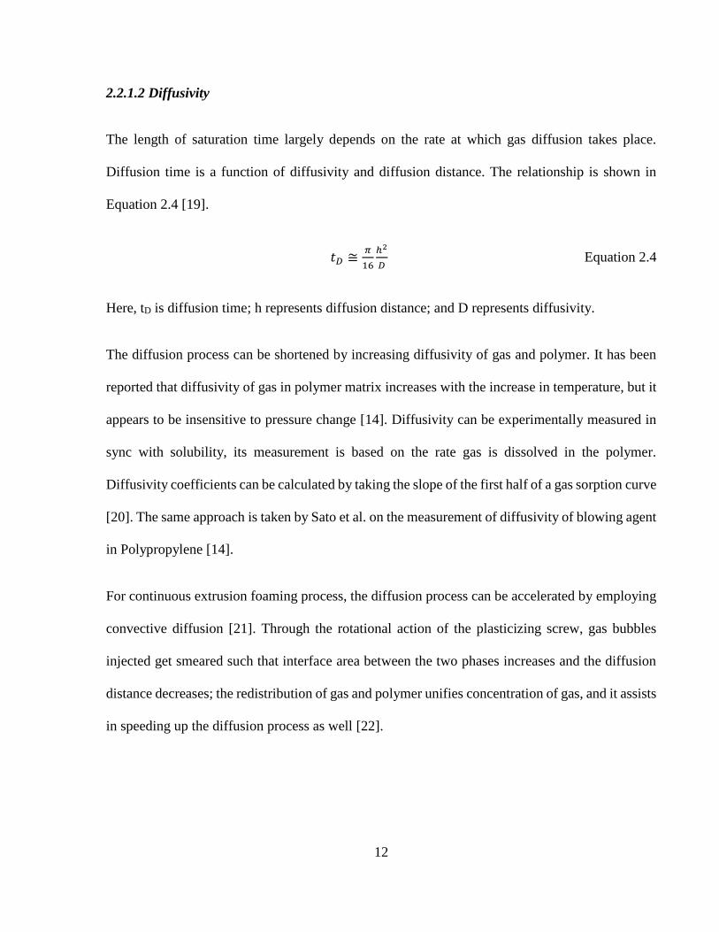
The length of saturation time largely depends on the rate at which gas diffusion takes place.
Diffusion time is a function of diffusivity and diffusion distance. The relationship is shown in
Equation 2.4 [19].
𝑡𝐷 ≅𝜋
16
ℎ2
𝐷 Equation 2.4
Here, tD is diffusion time; h represents diffusion distance; and D represents diffusivity.
The diffusion process can be shortened by increasing diffusivity of gas and polymer. It has been
reported that diffusivity of gas in polymer matrix increases with the increase in temperature, but it
appears to be insensitive to pressure change [14]. Diffusivity can be experimentally measured in
sync with solubility, its measurement is based on the rate gas is dissolved in the polymer.
Diffusivity coefficients can be calculated by taking the slope of the first half of a gas sorption curve
[20]. The same approach is taken by Sato et al. on the measurement of diffusivity of blowing agent
in Polypropylene [14].
For continuous extrusion foaming process, the diffusion process can be accelerated by employing
convective diffusion [21]. Through the rotational action of the plasticizing screw, gas bubbles
injected get smeared such that interface area between the two phases increases and the diffusion
distance decreases; the redistribution of gas and polymer unifies concentration of gas, and it assists
in speeding up the diffusion process as well [22].
13
2.2.1.3 Plasticization Effect of Gas
The plasticization effect refers to when a secondary phase, usually consisted with small molecules
substances, reduces the melt properties of the primary polymer matrix material and induces higher
degree of flexibility to the material over a range of temperatures [23]. As the environmentally
friendly inert gases have gained popularity as physical blowing agents in the foaming industry,
they have naturally become the inevitable plasticizer in polymer melts due to their small molecule
sizes. Their plasticization effects need to be addressed as they can affect many aspect in the
foaming process [24].
The mechanism of the plasticization effect is described by Doolittle with the free volume theory
[25]. The free volume is defined as the difference between the volume observed at absolute zero
temperature and the volume measured at any other given temperatures. At absolute zero
temperature, there is no vibration or oscillation on the molecular level; therefore molecules are
nicely packed together, occupying little space. As the temperature starts to elevate, molecules start
to oscillate and occupy an imaginary free volume around them. The same principle applies when
gas is dissolved in the polymer. As gas molecules diffuse through the polymer matrix, swelling
occurs; the additional free volume created makes changes in the polymer chain conformation
easier, which effectively reduces the stiffness of the material [25]. The plasticization effect affects
foaming processes in a variety of aspects including the change in glass transition temperature,
viscosity, diffusivity, and etc. [24].
The plasticization effect of gas increases the diffusivity of the polymer matrix. Diffusivity of the
matrix is increased due to the polymer swelling phenomenon and the additional free volume; gas
molecules can jump to large voids as long as they are able to overcome attraction force from

14
neighbouring molecules [25]. In extrusion foaming, Chen et al. reported significant increase in
cell growth rate as the result of the increase in diffusivity caused by the plasticization effect; he
proposed a diffusion-induced cell growth mechanism [23].
2.2.2 Cell Nucleation
Cell nucleation can be defined as the conversion of small group of gas molecules into energetically
stable groups or pockets. A thermodynamic instability, either a rapid heating or pressure drop will
cause the formation of bubbles within polymer melts [22].
The cell nucleation is in generally initiated as the one-phase polymer-gas solution experiences a
rapid depressurization process which causes the solubility of gas in the polymer matrix to decrease.
The sudden change in solubility causes a super-saturation in the system; gas bubbles are nucleated
as the thermodynamically instable system seeks for a metastable thermodynamic state. The
dynamic nature of cell nucleation makes it a dominate factor affecting many aspects of foaming
including the early cell growth, final cell density and the final cell morphology [24].
In polymeric foaming, cell nucleation can be classified into homogeneous nucleation,
heterogeneous nucleation, and pseudo-classical nucleation [22]. The Classical Nucleation Theory
developed by Gibbs [26] consists theoretical predictions of thermodynamic instability limits for
homogeneous nucleation and heterogeneous nucleation. Gibbs theory suggests that there exists a
critical bubble size corresponding to the thermodynamic instability equilibrium point, where the
free energy of the system is at maximum; this energy state is referred to as the free energy barrier.
He suggests that bubbles larger than the critical radius grows spontaneously, and bubbles smaller

15
than the critical radius collapse. Pseudo-classical nucleation emerged in the plastic foaming
industry as researchers reported that nucleation of gas bubbles actually occurs earlier than that
predicted by the Classical Nucleation Theory [27]. It is claimed that the free energy barrier for
nucleation can be lowered if the nucleation is initiated at a pre-existing micro-void site.
2.2.2.1 Classical Bubble Nucleation
Homogeneous nucleation involves the formation of gas bubbles from a homogeneous liquid phase
with no pre-existing cavities or micro-voids. According to the classical nucleation theory, the
critical radius of a sustained bubble and the free energy barrier for homogenous nucleation to take
place can be determined from Equations 2.5 and 2.6 respectively [28].
𝑅𝑐𝑟 =2𝛾𝑙𝑔
𝑃𝑏𝑢𝑏,𝑐𝑟−𝑃𝑠𝑦𝑠 Equation 2.5
𝑊ℎ𝑜𝑚 =16𝜋𝛾𝑙𝑔
3
3(𝑃𝑏𝑢𝑏,𝑐𝑟−𝑃𝑠𝑦𝑠)2 Equation 2.6
Here, Rcr represents critical radius, Whom represents the free energy barrier for homogenous
nucleation, 𝛾𝑙𝑔 is the interfacial tension between polymer and gas, Pbub,cr is the critical bubble
pressure and Psys is the system pressure. During foaming, the depressurization process causes Psys
to decrease, effectively increasing the degree of super-saturation (Pbub,cr-Psys). According to
Equations 2.5 and 2.6, the higher the degree of super-saturation, the lower the critical bubble radius
and the free energy barrier. This is the fundamental reason why pressure drop rate has such
significant impact on the foaming behavior [28].

16
It has also been demonstrated experimentally that the cell density of foam can have strong
dependency on the gas content [12]. While the high gas concentration increases the initial degree
of super-saturation, it has also been shown to decrease the interfacial tension between polymer and
gas [29], hence decreasing the free energy barrier for nucleation.
Heterogeneous nucleation takes place when impurities such as nucleating agent particles are
present in the polymer matrix. It takes place by substituting a higher energy state solid-liquid
interface with a lower energy state solid-gas interface. The energy barrier of a heterogeneous
nucleation is significantly reduced from that of a homogenous nucleation [30], as would be
indicated from Equation 2.7.
𝑊ℎ𝑒𝑡 =16𝜋𝛾𝑙𝑔
3 𝐹
3(𝑃𝑏𝑢𝑏,𝑐𝑟−𝑃𝑠𝑦𝑠)2 Equation 2.7
Here, F is simply a geometric factor equating to the volumetric ratio of a heterogeneously nucleated
bubble to that of a complete sphere with the equal radius of curvature. The F term is always less
than unity by definition. An elaborate explanation can be found from Fisher’s paper [30].
2.2.2.2 Pseudo-Classical Bubble Nucleation
Lubetkin et al. experimentally demonstrated that bubble nucleation takes place sooner than would
be predicted by the classical nucleation theory [27]. Which makes the assumption of the classical
nucleation theory - there exists no micro-void in the matrix prior to bubble nucleation, invalid. The
pseudo-classical nucleation proposes that the polymer matrix cannot be perfectly wetted to the

17
impurity particles or fillers present and the pre-existing voids can serve as seeds for bubble
nucleation, reducing the free energy barrier [31].
2.2.2.3 Stress Induced Nucleation
During the cell nucleation process, stress experienced by the polymer melt can induce nucleation
greatly. Guo et al. investigated the correlation between shear stress and the cell density by
conducting foaming with a slit die [32]. They observed higher cell density along the cell wall
region where shear is more dominant and lower cell density in regions where shear is less
dominant. Leung et al. visualized the nucleation process of a polystyrene-talc composite in a static
foaming chamber [33]. They observed cells to nucleate around existing cells in a chain reaction
fashion, attributed the clustering effect of cell nucleation to the extensional stress imposed by the
expanding bubbles. They compared the nucleating ability of talc particles of different sizes and
concluded that the larger sized talc particles induce more stress variation around themselves,
enhancing stress-induced nucleation.
In summary, the free energy required for nucleation is generally much lower than that required for
homogeneous nucleation. Therefore, additives such as talc, nano-clay or nanotubes can be added
to decrease the energy required to create bubbles and therefore enhance cell nucleation. However
there are certain criteria to be fulfilled for being an ideal nucleating agents [34]. Three of the most
important criterion are: first, highest nucleation efficiency can only be achieved when the
nucleation on the nucleating agents surface is energetically favored and is relative to homogeneous

18
and heterogeneous nucleation; secondly, ideal nucleating agents have uniform size and surface
properties; thirdly, ideal nucleating agents are easily dispersible [34].
2.2.3 Cell Growth
After cells are nucleated, they start to expand due to gas diffusion from the polymer matrix as the
pressure inside the cell is higher than the surrounding pressure. Cells tend to grow so as to decrease
the pressure difference between inside and outside [22]. As cells continue to grow, the pressure
difference eventually expires and the cell growth mechanism becomes diffusion dominant.
Diffusion of gas molecules takes place where there is a strong gas concentration gradient, both
between polymer-gas solution and nearby cells, as well as through the foam sample skin. The
ability to cool the foam and stabilize the cellular structure is vital as it determines the foam
morphology as well as the amount of gas that is being diffused out [24].
The combined effect of excessive cell growth and poor material melt strength leads to the failure
to stabilize the cellular structure of foam; it can take place in the form of cell coalescence, cell
coarsening and cell collapse [22]. During cell growth, the cell walls separating neighboring cells
grow increasingly thin. Cell coalescence takes place when the thin cell wall collapses as the result
of stretching, and neighboring cells join to form one. Cell coalescence is especially undesirable in
close-cell foams. On the other hand, if the difference in gas concentration causes gas to diffuse
from one cell to another, the cell losing gas would eventually decrease to below the critical radius
and collapse while the other cell grows. This phenomenon is called cell coarsening. In addition, if
19
the cell collapse happens to be the result of gas molecules being diffused out of foam, the
mechanism is called cell collapse [22].
The importance of material melt strength in the stabilization of the cellular structure cannot be
overly emphasized. There have been many attempts in the literature to improve the foam
morphology through enhancing material melt strength. Researchers have compared melt strength
and foaming between materials of different molecular structure. They observed that while linear
materials exhibit poor melt strength, branching can significantly enhance the material’s ability to
stabilize cell structures [35] [36] [37]. Naguib et al. demonstrated the temperature dependency of
foam expansion [38]. While severe cell coalescence, coarsening and/or collapse takes place at high
foaming temperatures, lowering the temperature can help to enhance the melt strength which
prevents excessive gas loss.
2.3 Blowing Agent
Polymeric foam is generally characterized by blowing agent indwelling and expansion within the
polymeric matrix. Unstable foaming like boiling occurs and must be sustained by the surrounding
polymeric material to form a stable cellular product. In most cases, blowing agent is virtually
indispensable in the polymeric foaming process. There are a great variety of organic and inorganic
blowing agents suitable for the process. From the nature of gas formation, it can be classified as
physical blowing agent (PBA) and chemical blowing agent (CBA) [39]. The former is generally
referred to as a variation of state, such as saturated liquid to liquid/vapor, vapor, then supercritical
fluid state, in the processing of the blowing agent. The blowing agent never changes its

20
composition, except the state. However, CBA is known by its formation path, such as heat-induced
chemical decomposition. It begins in solid state, then evolves into gas when heat-activated
decomposition occurs. In general, inorganic volatile gases, nitrogen and carbon dioxide, are
evolved as the main components. In short, both PBA and CBA have been well established for
specific foaming processes [39].
2.3.1 Physical blowing agent (PBA)
Physical blowing agent (PBA) is known with its suitability in the foaming process and foamed
product. In the early days, it was credited by its superior solubility in thermoplastic polymers [39].
Munters and Tandberg [40] disclosed a blending method and its immediate implementation in the
foaming of polystyrene as early as 1935. Almost at the same time, halogenated hydrocarbon was
recognized as a very friendly and stable agent for cryogenic system and, in turn, polymeric
foaming. Since then, foaming with physical blowing agents became an intriguing development
subject. During World War II, quite a few floating devices were made of PBA for military usages.
In the 1950s, the foundations for foam extrusion and polyurethane foam with PBAs as auxiliary
blowing agents were firmly laid [39].
Physical blowing agents (PBAs) can be incorporated within the polymer matrix using various
methods: (i) Physical blending and physical dissolution, (ii) Physical blending and chemical
decomposition, (iii) Physical dissolution, and (iv) Chemical reaction and encapsulation [39].
Among these, physical blending and dissolution is considered the most commonly implemented
method in the industry of polymeric foams. Under high pressure, and sometimes elevated

21
temperature, a physical blowing agent can be compressed as a critical or super critical fluid,
depending on the processing temperature and the critical temperature of the fluid. It then contacts
and dissolves into the polymeric melt to form a saturated polymer/gas system, which can foam
when subjected to a lower pressure (or higher temperature) environment [39].
PBAs are generally used for making low-density foam under 0.2 g/cm3. Before 40 years, CFC
was mainly used as a physical blowing agent due to its low thermal conductivity, soluble, volatile
and nontoxic nature. But it easily reacts with ozone and damage the ozone layer that raised the
serious issue of global warming. In the 1987, Montreal Protocol was signed to discontinue the
manufacturing of halogenated hydrocarbons to minimize the ozone layer damage [41]. The
alternative of halogenated hydrocarbons, such as butane and pentane were commonly used in the
production of low-density foams because it has relatively low price and can be injected into the
foaming equipment efficiently. But they are flammable and the use of such blowing agents
introduces flammability hazards on the shipping and handling of the finished foam products [22].
Considering these environmental and safety issues, these PBAs are replaced by inert gases such as
carbon dioxide (CO2) and nitrogen (N2) [39].
The process of polymeric physical foaming is divided into three main steps. In the first step, PBA
dissolves and saturates into the polymer at a high pressure. The phase separation between the
dissolved gas and the polymer matrix will occur by releasing the system pressure or increasing the
system temperature. The new phase formation known as nucleation, can originate from self-
structural adjustment. Cells of gaseous phase will start to nucleate within the polymer matrix at
the defects or nucleating agents. Dissolved gas will slowly diffuse into these cells and expand the
cells. In the last step, the cell expansion stops and stabilized the cellular structure. The physical
22
foaming phenomena can be applied in continuous processes such as extrusion and injection
molding, and batch processes such as compression molding to produce cellular foams for various
applications [39].
2.3.2 Chemical blowing agent (CBA)
It is well known that some chemicals are capable of liberating gaseous components via reactions
and/or thermally induced decomposition. When these occurrences take place within the polymeric
melt, the decomposing chemical automatically acts as a blowing agent. Some chemicals fit certain
polymer processing nicely. These kinds of chemicals are referred to as chemical blowing agents
(CBAs) [39].
CBAs are mixture of chemicals that release gas like CO2 and/ or N2 upon thermal decomposition
at a specific temperature range. CBA are generally used to make high and medium density foam
plastic and rubber. They are rarely used to make foam with densities below 400 kg/m3 because
they are expensive. For example, CO2 and N2 released form CBA cost about 10 times more that
used from a cylinder. The quantity of the blowing agent needed for the foam processing is very
low typically around 2 wt% [42].
CBA refers more to process than product. In comparison to the requirements set for the suitability
of PBAs for foaming applications, the requirements for the processing suitability of CBAs appear
to be more stringent. This is so because chemical reactions and/or heat are involved, so that the
dispersion of the blowing agent throughout the melt and the heat sensitivity of the polymer impose
serious concerns that aggravate the processing of polymeric foams using CBAs. In other words,

23
heat sensitive polymer and the required shear to attain dispersion are legitimate material and
processing issues. Moreover, common CBAs possess a decomposition temperature 100°C above
the melting point of the semi-crystalline polymers. Removing the extra heat usually becomes a
serious processing bottleneck [39].
The decomposition of a CBA not only depends on the processing thermal profile, but also on its
residence time under the decomposition temperature. If it requires too high a temperature to trigger
its decomposition, or takes too much time to complete the decomposition reaction, it will be
extremely difficult to obtain desired results.
Most chemical reactions can either absorb heat or liberate heat, depending on the entropy
summation of reactants vs. products. In contrast, when products become more active, it is generally
required to add heat to proceed with the reaction. This type of reaction is referred to as being
endothermic in nature. When the products possess less enthalpy than that of the reactants, it is
exothermic. However, actual reactions often involve a primary reaction and a secondary reaction,
such as further decomposition, or reaction between the reactant and the primary product. Net
enthalpy balance is required to determine its thermal nature [39]. The chemical reactions can be
either endothermic or exothermic depends on the type of chemicals. Endothermic CBAs absorb
the heat energy while decomposition process and they have wider decomposition temperature
range. Sodium bicarbonates and their altered forms falls into the endothermic-grade CBAs
categories. These CBAs releases mainly carbon dioxide gas and water vapor during thermal
reaction that helps to create the foam structure [43] [44] .
On the other hand, in exothermic CBAs release heat during the thermal decomposition which is
more spontaneous and is harder to be terminated once the reactions are initiated. Exothermic CBAs

24
like Azo compounds such as Azodicarbonamide and their derivatives and 4, 4-oxybis (benzene
sulfonylhydrazide) are commercially used in foam processing of LDPE and EVA. These
compounds manly release Nitrogen gas upon thermal decomposition. In the selection of a CBA
for a particular foaming process, the decomposition temperature, the decomposition rate, the type
of gas they liberate (CO2 or N2), the gas yield (the amount of gas liberated in cm3 per gram of
CBA), and the pressure generated from these gases are the general characteristics which need to
be considered [43] [45].
2.4 Foaming Processes
Microcellular foaming technology is very versatile, and it can be implemented with many
conventional plastic processing technologies. Foaming process can be carried out by either batch
or continuous process.
2.4.1 Batch Foaming Process
In batch foaming process, solid polymer is first placed in a pressurized chamber where it is
submerged with inert blowing agent for an extensive period of time for saturation. The saturation
time depends on the polymer sample size and diffusivity of the gas-polymer system, which is
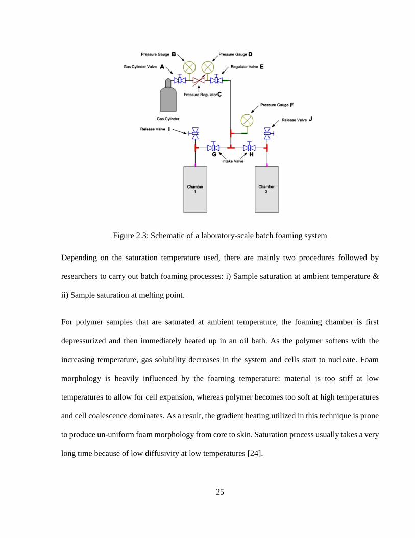
dependent on the saturation temperature [24]. Figure 2.3 shows a schematic of a typical laboratory-
scale batch foaming system [33].
25
Figure 2.3: Schematic of a laboratory-scale batch foaming system
Depending on the saturation temperature used, there are mainly two procedures followed by
researchers to carry out batch foaming processes: i) Sample saturation at ambient temperature &
ii) Sample saturation at melting point.
For polymer samples that are saturated at ambient temperature, the foaming chamber is first
depressurized and then immediately heated up in an oil bath. As the polymer softens with the
increasing temperature, gas solubility decreases in the system and cells start to nucleate. Foam
morphology is heavily influenced by the foaming temperature: material is too stiff at low
temperatures to allow for cell expansion, whereas polymer becomes too soft at high temperatures
and cell coalescence dominates. As a result, the gradient heating utilized in this technique is prone
to produce un-uniform foam morphology from core to skin. Saturation process usually takes a very
long time because of low diffusivity at low temperatures [24].

26
If sample is saturated at around the material’s melting point, the chamber can be directly
depressurized to initiate cell nucleation and growth. Subsequent cooling enhances melt strength of
material and stabilizes cellular structure of foams produced. High saturation temperature dictates
high diffusivity of gas through polymer matrix, reducing saturation time. In addition, heating can
be more uniformly applied to the polymer, so that the foam morphology obtained is more
consistent as well [24].
The main drawback of this process is that it takes long time to saturate the polymer with gas due
to low diffusion rate of gas into the polymer. The batch foaming process is also not cost effective.
To overcome this drawback, a cost-effective, continuous extrusion process was developed to
produce microcellular foam based on the same principle of thermodynamic instability [22].
2.4.2 Continuous Foaming Process
Continuous foaming process is basically two types: i) Extrusion foaming and ii) Foam injection
molding. They are cost effective and have higher productivity than batch foaming process. Figure
2.4 shows a schematic of an extrusion foaming system.
The continuous extrusion process begins from the melting of polymer pellets as they are fed from
the extruder hopper. For PBA extrusion, blowing agent (typically CO2/N2) is injected inside the
extruder barrel through a gas injection port by using a positive displacement pump (thereafter
referred as the syringe pump). The syringe pump is capable of measuring the output flow rate very
precisely; it is useful for regulating the flow rate of blowing agent being injected at any given
pressure. The weight percentage of blowing agent being injected can be quickly calculated by

27
measuring of the foam output rate. On the other hand, for CBA extrusion, CBA pellets are dry
blended or compounded with polymer pellets as per requirement and then they are fed from the
extruder hopper. In CBA foaming, syringe pump is not required as the required gas is supplied in
the form of chemical blowing agent. CBA gas decomposition can be triggered by controlling the
temperature profile of the extruder.
Figure 2.4: Schematic of a continuous extrusion foaming system
Gas-polymer mixture is pushed along the extruder through the rotating action of the screw. The
resistance experienced by the pellets and the rotating screw generate significant heat to help to
melt the polymer; at the same time, the shear fields produced by the screw motion apply dispersive
mixing to the blowing agent and polymer matrix. To increase the efficiency of mixing, irregular
mixing blades as well as static mixers are often utilized to redistribute local gas concentration and
increase the interfacial area between the two phases. Mixing elements in the extrusion system also

28
enhance uniform temperature distribution in the polymer melt. High temperature and high pressure
are maintained to expedite the diffusion process.
Once a single phase solution is obtained, adequate cooling is applied to the solution to obtain
quality foam structure. If the melt temperature is too high, the melt will not have the necessary
melt strength to stabilize and maintain the cellular structure of foam before it is solidified. Since
plastics are generally thermal insulating materials, a uniform cooling of the polymer melt is not
easy to achieve. A heat exchanger is often used as a cooling channel, where polymer melt can be
cooled uniformly effectively. A second extruder is sometimes attached at the outlet of the first
extruder, forming a tandem extrusion system; the second extruder is used exclusively for the
progressive uniform cooling of the polymer melt.
Once the one-phase solution is cooled to the desired temperature, it is pushed through the die where
the depressurization takes place. The rapid drop in pressure induces a high degree of
thermodynamic instability that causes phase separation and cells to nucleate. As the pressure
decreases, the solubility of gas in the polymer matrix decreases. The polymer-gas system seeks for
lower free energy state such that new thermodynamic stability can be established; gas molecules
start to cluster and form cell nuclei. These newly formed cell nuclei provide relatively small mean
distance for the gas molecules to diffuse through, free gas molecules are more prone to be attracted
to the existing nearby nuclei where lowered free energy can be achieved than forming new nuclei
[1]. This accumulation of gas molecules into existing voids marks the initial stage of cell growth.
As cells continue to expand, adequate cooling is required to increase melt viscosity and melt
strength, which helps to stabilize the cell structures and suppress excessive cell growth [38].

29
2.5 Factors affecting Foam Extrusion
2.5.1 Crystallization Kinetics
In a continuous foaming process, polymer transforms from solid to molten state and finally, to
solid state to get the final shape of the foam for the applications. The former is called melting and
the latter solidification or crystallization. In general melting is done before introducing gas, but
foaming and solidification takes place at the same time with different rates. Generally,
solidification is relatively slower process than Foaming, and plays an important role in degree of
expansion and final foam properties [39].
In semi crystalline polymers, crystallites are dispersed into an amorphous region. The fraction of
the polymer that is fully crystalline is known as the crystallinity. Depending upon the polymer
chain structure, crystals can be formed within a certain time to induce the resistance for bubble
expansion to have a fine cell structure. The competing mechanisms between expansion and
material strength to hold expansion is an interesting kinetic topic for achieving optimal foam
structure [39].
The crystallites are nucleated from the melt at certain range of temperature during nucleation and
afterwards continue to grow during the growth phase to form three-dimensional conglomerations
of crystallites known as spherulites. The spherulite growth rate is quicker than the nucleation rate
as the required free energy for spherulite to grow is lower than that of required for nucleation rate.
The crystallization rate increases under stress because the molecular chains orient and become
more packable due to stress. Nucleation takes place in one of the two ways; Thermal or
instantaneous nucleation which occurs at the beginning of the process when nuclei appear

30
instantaneously. It is assumed that it depends only on temperature and to be independent of time
and cooling rate. Therefore, the grown crystals will be of approximately equal sizes. The other
way of nucleation is thermal or sporadic nucleation which appears in the liquid phase during the
process. And the activated nuclei appear at a constant rate per unit volume [46].
Normally, two types of nucleation are found for polymer crystallization: Primary and secondary
nucleation. During the primary nucleation, three dimensional crystal growth occurs rapidly and
spontaneously after potential nucleus reaches a critical size. If nucleation occurs without any
preformed nuclei or any foreign surfaces, primary nucleation is also called homogeneous
nucleation. On other hand, secondary nucleation occurs when the chain segments are added to the
existing crystal surface. The main difference between primary and secondary nucleation is in
Gibbs free energy or energy required for the formation of a critical size nucleus [26].
Gibbs developed the classical nucleation theory based on the assumption, that energy variations in
the super-cooled phase can overcome the nucleation barrier caused by the surface of the crystal
[26] [47] [48]. Based on this assumption, Turnbull and Fisher [49] developed a formula to estimate
the primary nucleation rate as a function of the crystallization temperature, using the Williams-
Landel-Ferry(WLF) [50] equation which universally describes the temperature dependence of
polymer melt viscosity: Based on the surface or secondary nucleation theory , Lauritzen and
Hoffman [51] derived a linear growth rate equation, which comprises fold surface energy, lateral
surface energy, heat of fusion and lamellar thickness terms into the Gibbs free energy to explain
the linear growth rate of spherulites.

31
2.5.2 Filamentary Die Design in Foam Extrusion
Different Length and diameter of the filamentary die induce different die pressure and pressure
drop rates and that helps to get different foam structure [12]. Xu et al. [52] designed three
interchangeable groups of 9 dies to have either different pressure drop rates while having the same
die pressure and flow rates, or different die pressure while having the same pressure drop rates and
flow rates. They assumed that the polymer/gas solution flow through die can be described by the
‘Power law’ in the flow through a tube which states that the viscosity of the polymer-gas matrix is
shear rate dependent and the pressure drop over the length of a nozzle for a non-Newtonian fluid
in a fully developed flow can be expressed as equation 2.8 [53].
𝑃𝑑𝑖𝑒 = −2𝑚𝐿
𝑅3𝑛+1 [(3 +1
𝑛)
𝑄
𝜋]
𝑛
Equation 2.8
The residence time t of the polymer/gas solution in the nozzle can be given by equation 2.9,
𝑡𝑟𝑒𝑠𝑖𝑑𝑒𝑛𝑐𝑒 = 𝐿
𝑉𝑎𝑣𝑔=
𝐿
𝑄 𝜋𝑅2⁄=
𝜋𝑅2𝐿
𝑄 Equation 2.9
Therefore, the pressure-drop rate can be estimated by equation 2.10.
𝑑𝑝
𝑑𝑡 ≈
∆𝑝
∆𝑡= −2𝑚 (3 +
1
𝑛)
𝑛
(𝑄
𝜋𝑅3)𝑛+1
Equation 2.10
Using these equations, they measured the pressure drop rate and find the effect on the cell density
of extruded PS foams. The experiment results discovered that geometry of the die is important
parameter to govern the cell density due to its effect on the pressure drop rate across the die. The
die back pressure which depends on the die length and die diameter, significantly affect the cell
morphology.

32
Patrick et al. [54] also investigated the effect of pressure drop rate on cell nucleation and growth
behaviors of non-crosslinked high melt strength Polypropylene. Both the cell population density
and the volume expansion ratio increased as the die pressure drop rate increased and the effect of
die pressure on nucleation and expansion behavior was negligible as long as the die pressure
remained above the solubility pressure of CO2.
2.5.3 Governing Mechanism of Volume Expansion
Generally, the main purpose of foaming is to make low density foams with high expansion to save
material cost. Therefore, it is essential to get the desirable volume expansion ratio, in other words,
void fraction. Moreover, the effective control of the volume expansion is necessary to enhance the
efficiency of costly blowing agents. Continuous attempt has been made to understand the
mechanism of volume expansion in foam extrusion.
Behravesh et al. [10] explained that initial bump at the die exit promotes gas loss during volume
expansion. The thickness and the temperature of the cell walls are crucial in determining the rate
of gas escape as the gas escape from foams takes place through cell-to cell diffusion. The thickness
of cell walls gradually decreases as the cells grow. Because of the cooling through convection at
die orifice and isentropic expansion of gas, the temperature of the cell walls decreases. When the
temperature of the cell wall is high enough, the cells grow very fast and the thickness of cell wall
decreases and gas will escape quickly through the hot thin cell walls. Therefore die temperature
determines the volume expansion of extruded foams.
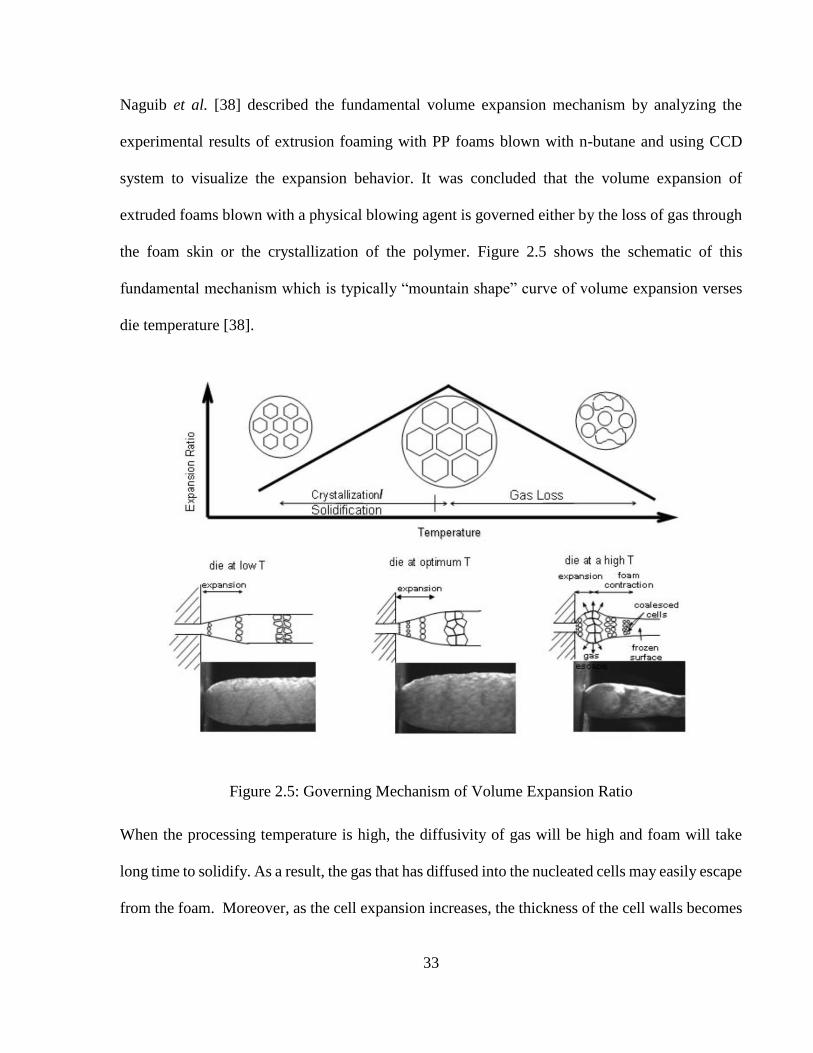
33
Naguib et al. [38] described the fundamental volume expansion mechanism by analyzing the
experimental results of extrusion foaming with PP foams blown with n-butane and using CCD
system to visualize the expansion behavior. It was concluded that the volume expansion of
extruded foams blown with a physical blowing agent is governed either by the loss of gas through
the foam skin or the crystallization of the polymer. Figure 2.5 shows the schematic of this
fundamental mechanism which is typically “mountain shape” curve of volume expansion verses
die temperature [38].
Figure 2.5: Governing Mechanism of Volume Expansion Ratio
When the processing temperature is high, the diffusivity of gas will be high and foam will take
long time to solidify. As a result, the gas that has diffused into the nucleated cells may easily escape
from the foam. Moreover, as the cell expansion increases, the thickness of the cell walls becomes
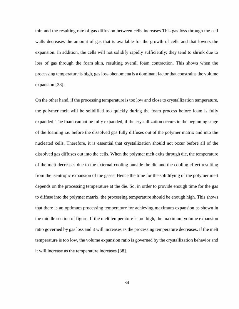
34
thin and the resulting rate of gas diffusion between cells increases This gas loss through the cell
walls decreases the amount of gas that is available for the growth of cells and that lowers the
expansion. In addition, the cells will not solidify rapidly sufficiently; they tend to shrink due to
loss of gas through the foam skin, resulting overall foam contraction. This shows when the
processing temperature is high, gas loss phenomena is a dominant factor that constrains the volume
expansion [38].
On the other hand, if the processing temperature is too low and close to crystallization temperature,
the polymer melt will be solidified too quickly during the foam process before foam is fully
expanded. The foam cannot be fully expanded, if the crystallization occurs in the beginning stage
of the foaming i.e. before the dissolved gas fully diffuses out of the polymer matrix and into the
nucleated cells. Therefore, it is essential that crystallization should not occur before all of the
dissolved gas diffuses out into the cells. When the polymer melt exits through die, the temperature
of the melt decreases due to the external cooling outside the die and the cooling effect resulting
from the isentropic expansion of the gases. Hence the time for the solidifying of the polymer melt
depends on the processing temperature at the die. So, in order to provide enough time for the gas
to diffuse into the polymer matrix, the processing temperature should be enough high. This shows
that there is an optimum processing temperature for achieving maximum expansion as shown in
the middle section of figure. If the melt temperature is too high, the maximum volume expansion
ratio governed by gas loss and it will increases as the processing temperature decreases. If the melt
temperature is too low, the volume expansion ratio is governed by the crystallization behavior and
it will increase as the temperature increases [38].

35
Xu et al. [52] pointed out that the inevitable and unwanted premature cell growth inside a die has
a significant effect on volume expansion ratio. These premature cells grow at the die exit and
resulted in big size cells. This big size cells causes instantaneous expansion at the die exit due to
the pressure drop. These phenomena enhance the gas loss. The amount of the premature cell
growth is estimated by cell density, premature cell growth time, and premature cell growth rate,
which are directly influenced by the die geometry. When the premature cell growth is too much,
the volume expansion ratio of the extruded form will be significantly dropped. Equation 2.11 was
given to calculate the amount of premature cell growth Mpremature, in a filamentary die.
𝑀𝑝𝑟𝑒𝑚𝑎𝑡𝑢𝑟𝑒 ≈ 4
3 𝜋𝑁𝐶𝑠 ∙ (𝐷𝑡𝑃𝑟𝑒𝑚𝑎𝑡𝑢𝑟𝑒)
3
2 + 𝑀0 Equation 2.11
Where N = Cell density, 𝐶𝑠 = dissolved gas concentration per unit volume, 𝐷= diffusivity,
𝑡𝑃𝑟𝑒𝑚𝑎𝑡𝑢𝑟𝑒 = premature cell growth time, 𝑀0= undissolved gas amount per unit volume
If P< Psolubility all the injected gas cannot dissolve into the polymer melt and term (𝑀0) in the
equation can be expressed as equation 2.12.
𝑀0 ≥ 𝑃𝑠𝑜𝑙𝑢𝑏𝑖𝑙𝑖𝑡𝑦− 𝑃
𝑃𝑠𝑜𝑙𝑢𝑏𝑖𝑙𝑖𝑡𝑦 𝑥 𝐶𝑖𝑛𝑗𝑒𝑐𝑡𝑒𝑑 Equation 2.12
Where 𝑃𝑠𝑜𝑙𝑢𝑏𝑖𝑙𝑖𝑡𝑦 = solubility pressure,
𝐶𝑖𝑛𝑗𝑒𝑐𝑡𝑒𝑑= amount of injected gas.
The value of M0 can be minimized by proper mixing of the polymer gas solution and providing
enough time for the gas dissolving and can be removed if the P is maintained above P solubility

36
[55]. It is also found that the volume expansion ratio would be dropped if the amount of premature
cell growth exceeds some critical value.
2.5.4 Residence Time of the Polymer in the Extrusion System
Residence time of the polymer in the extrusion system is a key factor for CBA based foam
extrusion. Increasing screw speed of the extruder increase the overall throughput, thus reducing
the residence time. Residence time can be measured with various theoretical and experimental
models [56]. Among all those models Tracer model is the most acceptable experimental model. In
this model, a colored bead is fed into the hopper along with polymer resin. Time count starts when
bead touches the first thread of the screw. Colored bead travels along the extruder, gets mixed and
exits via die. When color is first visible in the extrudate it is called first trace time and when the
color fades out it is called last trace time. Wolf et al. [57] showed that in a typical extrusion system
the concentration of the color is maximum at 15-20% of the first trace time to the last trace time.
That time is considered as residence time of the polymers. Figure 2.6 illustrates his experimental
findings [57].
Figure 2.6: Determination of the Residence Time

37
2.6 Characterization of the Foam Samples
Polymeric foams are usually specified in terms of foam density, volume expansion ratio & void
fraction and cell density & cell morphology. These parameters are dependent on the processing
conditions as these parameters indicate the degree of the cell nucleation and the expansion which
have been controlled during the foam processing.
2.6.1 Foam Density
Foam density is one of the structural parameters that directly represent the density reduction of the
un-foamed material [22]. The foam density (ρf) can be calculated as:
𝜌𝑓 = 𝑀
𝑉 Equation 2.13
Where M = the mass of foam sample, g V = the volume of foam sample, cm3
Water submerging and displacement is a common and most accurate method for determining the
bulk density of solid and closed-cell foam specimens.
2.6.2 Volume Expansion Ratio & Void Fraction
The relative density of the form is defined by the ratio of foamed part density to its un-foamed
material density. The relative density of a foam specimen is often used in the evaluation of foam’s
volume expansion and it is the reciprocal of its volume expansion ratio [22]. The volume expansion

38
ratio (VER) of a foam sample can be calculated as the ratio of the bulk density of pure material to
the bulk density of the foam sample as follows:
𝑉𝐸𝑅(𝜑) = 𝜌𝑝𝑜𝑙𝑦𝑚𝑒𝑟
𝜌𝑓 Equation 2.14
In addition to using the volume expansion ratio, researchers also use void fraction (Vf) to describe
the amount of void in the foam, and it is defined as:
𝑉𝑓 = 1 − 𝜌𝑓
𝜌𝑝𝑜𝑙𝑦𝑚𝑒𝑟 Equation 2.15
The foam density, volume expansion ratio and the void fraction are related to each other, and all
are represents the material savings that results from the void volume that replaces the original
material.
2.6.3 Cellular Morphology and Cell Density
The cell morphology of a foam sample is typically examined with the aid of a scanning electron
microscope (SEM). The cell morphology of foam can be characterized by its cell size, cell density,
and cell size distribution. The cell size of the cells in the foam can be measured from the SEM
micrographs with the aid of image utility software. Cell population density is defined as the number
of cells per cubic centimeter volume relative to the un-foamed polymer. The cell density of the
foam structures can be estimated using the following equation:
𝐶𝑒𝑙𝑙 𝐷𝑒𝑛𝑠𝑖𝑡𝑦 = (𝑁𝑢𝑚𝑏𝑒𝑟 𝑜𝑓 𝐶𝑒𝑙𝑙𝑠
𝑎𝑟𝑒𝑎)
3
2∙ 𝑉𝐸𝑅 Equation 2.16

39
Where number of cells = total number of cells in the area which can be estimated from the
micrographs taken by a scanning electron microscope with the aid of image utility software.
Area = defined area, cm2,
VER = volume expansion ratio.
Cell size distribution of a foam specimen can be either estimated from the SEM micrographs or
measured with the mercury porosimetry or mercury immersion technique. The principle behind
mercury porosimetry is that mercury is a non-reactive, non-wetting liquid for most substances and
hence, sufficient pressure has to be applied to force its penetration into porous structure [58].

40
Chapter 3 High Temperature Extrusion Foaming of Polypropylene
with Chemical Blowing Agents
3.1 Introduction
Polymers are used everywhere in our day-to-day lives. In recent decades, the cost of raw polymer
resins is higher than ever. Foaming technology has been widely adopted to produce lightweight
polymeric foam products as an important strategy to reduce manufacturing cost as well as the
consumption of raw polymers. Polypropylene (PP) is the one of the most used synthetic polymer
worldwide. In 2013, the global market for polypropylene was about 55 million metric tons [9]. It
has been discussed earlier in section 1.2 that introducing foam structure in polymers increase their
mechanical properties and plays a big role in saving the material cost.
Introducing foam in PP extrusion is not a new work. But getting a higher void fraction in high
temperature extrusion is a challenge. Previous experiments have shown that Void Fraction drops
significantly when extrusion is done in high processing temperature [10]. On the other hand,
industries are usually reluctant to modify their existing extrusion system to get voids in their
product. As physical blowing agents need additional accessories to produce polymeric foams,
chemical blowing agent (CBA) can be the answer to their need. So the need of the extrusion
industries and the challenge of getting a good void fraction in high temperature extrusion is the
main driving force behind this fundamental study.

41
This chapter studies the production of polypropylene foams with CBAs on the single screw
extrusion system set to high processing temperature. Experimental results are presented that verify
the feasibility of the proposed ideas. It presents an effective strategy for promoting high void
fraction, fine-celled polypropylene foams. The effects of processing parameters such as the total
flow rate, the pressure drop rate, flow rate per hole, residence time and the materials parameters
such as different blowing agent and blowing agent content on the production of high void fraction,
fine-celled polypropylene foams are investigated.
3.1.1 Hypothesis
Kaewmesri et al. [11] have shown that with the increasing die temperature the expansion ratio and
cell density of the PP foam blown with CO2 goes down dramatically. At that rate of decline of the
expansion rate, it is a big challenge to achieve 5% of void fraction at 230°C of die temperature
with an even cell distribution and fair cell density with just supercritical CO2 as blowing agent. So
considering the fact, the target of this study is set to achieve around 30% void fraction with a fair
cell distribution (more than 106 cells/cm3) at 235°C die temperature.
To achieve this though target, it is very important to increase the understanding about the key
parameters that affect the quality of the foam. The quality of foam depends on two important
factors. They are - void fraction and cell density. These two factors are governed by six key
parameters. They are- blowing agent content, pressure drop rate, temperature, nucleating agent
content, polymer matrix and for processing with CBAs, residence time. In this research,
temperature profile is fixed and will be changed. And as we are using PP as base polymer, polymer

42
matrix is also fixed. Among others, Blowing & Nucleating agent and their content can be
controlled directly while pre-processing. But Pressure drop rate and residence time are controlled
by same machine parameter. To gain individual controllability of these two parameters, a
separation formulation is required. Figure 3.1 illustrates the idea of the quality of foam and it’s
affecting parameters.
Figure 3.1: Quality of foam and it’s affecting parameters.
Residence Time affects CBA activation time. So it is a very important parameter for CBA foaming.
Residence Time corresponds to the Total Throughput Rate. And Total Throughput Rate can be
controlled by Screw Speed. So we can control the residence time by controlling the screw speed.
Now, from equation 2.10, it is known that pressure drop rate is the function of power law indices,
radius of the die hole and flow rate per hole. In this research, the grade of PP and temperature is
fixed, so power law indices are constant. Also the die geometry will not be changed. So pressure
drop rate solely becomes function of flow rate per hole. So pressure drop rate can be controlled by
controlling the flow rate. And flow rate is controlled by screw speed. But Increasing Screw Speed
Quality of Foam
Blowing Agent Content
Pressure Drop Rate
TemperatureNucleating
Agent ContentPolymer Matrix
Residence Time (CBA only)
Void Fraction Cell Density

43
will both increase flow rate per hole and decrease Residence Time. So To decouple this effect, a
die with variable number of holes with same R was used. So for this improvised system, pressure
drop rate or flow rate per hole can be controlled by matching the number of holes with the increased
throughput from higher Screw Speed.
Chemical blowing agents (CBAs) will be used in this experiment. So the first strategy of this study
will be to find out the most suitable blowing agent for this study. Almost all commercially available
CBAs emits either CO2 or N2 gas as blowing agent. Lee et al. [59] have shown that in high
temperature extrusion foaming N2 gives almost no void fraction at 230°C die temperature, because
in high temperature N2 has a very high rate of cell to cell diffusion. Furthermore, N2 emitting CBAs
also emit toxic gases like CO and NH3 as by-product, which is harmful for industrial working
environment. For example, azodicarbonamide was most popular N2 based CBA widely used by
industries until European Union banned it in 2004 as it also emits toxic gases as by-products [60]
and World Health Organization linked azodicarbonamide to "respiratory issues, allergies and
asthma" for individuals at workplaces where azodicarbonamide is manufactured or handled in raw
form [61]. So N2 based CBAs should be avoided in this study.
CO2 based CBAs usually are 2 types based on the style of decomposition: i) Single Step
Decomposition and ii) Multi Step Decomposition. In this study at least 2 CBAs of both kind will
be tried to find out their influence in these experiments. Behravesh et al. [62] used ‘Hydrocerol’
from Clariant Inc. (Multiple Step Decomposition) [63] as CBA in his experiments which showed
some promising results in terms of cell density. Two different studies [64] [65] have found that
‘Ecocell L’ from Polyfil Corp. (Single Step Decomposition) [66] can be a very good CBA for PP
extrusion foaming specially for industrial applications. Mussig et al. [67] and Cavalieri et al. [68]

44
found that ‘Palmarole MB.BA.18’ from Adeka Corp. (Single Step Decomposition) [69] has a very
good compatibility with PP in extrusion. ‘Safoam FPE50’ (Multiple Step Decomposition) from
Reedy Chemicals [70] is another potential CBA to be used in this study. The best one will be used
to run experiments on the fundamental studies.
During the extrusion of polypropylene foams, the blowing agent that promotes foam expansion
may escape through the exterior skin of the foam resulting in contraction of the foam [10] [71]
[72] especially in high processing temperatures. Since the expansion of foam relies on the presence
of blowing agent within the foam, it is desirable to devise a means for preventing gas loss in order
to achieve a large volume expansion ratio or good void fraction. This gas can be prevented by
cooling down the die temperature [10]. But as high die temperature is a constraint in this
experiment, gas loss by this mean is inevitable. Using higher gas content can be an answer to the
problem.
Foaming with chemical blowing agents (CBAs) requires CBA activation/decomposition in the
extrusion barrel. When CBA reaches the decomposition temperature, it releases the blowing gas
in the barrel. So temperature is an important factor while processing polymeric foams with CBAs.
Behravesh et al. [62] have shown that while extrusion foaming with CBAs, if the CBA is exposed
for too long in the barrel the gas will decompose prematurely and it will escape through hopper
making a channel through solid bed. Figure 3.2 illustrates this phenomenon. This phenomenon
will result very bad polymeric foams.

45
Figure 3.2: Escaping of CBA gas through hopper due to long exposure to high T in barrel
So in this study, one of most important strategies will be to prevent the gas loss through hopper.
This phenomenon can be prevented by either lowering the temperature near hopper or run the
process quickly, in other words, increase the screw speed or total flow rate [62]. Increasing the
screw speed will reduce the residence time of the resins in the extruder barrel, which can be an
effective technique to get good void fraction. But increasing the screw speed will also increase the
overall throughput. Which is a major setback from industrial point of view. Most extrusion
industries use a definite polymer flow rate per hole to manufacture their product, and usually the
flow rate per hole is low. High overall throughput may be required to obtain 30% void in the
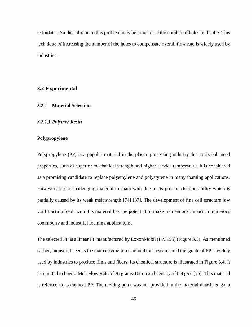
46
extrudates. So the solution to this problem may be to increase the number of holes in the die. This
technique of increasing the number of the holes to compensate overall flow rate is widely used by
industries.
3.2 Experimental
3.2.1 Material Selection
3.2.1.1 Polymer Resin
Polypropylene
Polypropylene (PP) is a popular material in the plastic processing industry due to its enhanced
properties, such as superior mechanical strength and higher service temperature. It is considered
as a promising candidate to replace polyethylene and polystyrene in many foaming applications.
However, it is a challenging material to foam with due to its poor nucleation ability which is
partially caused by its weak melt strength [74] [37]. The development of fine cell structure low
void fraction foam with this material has the potential to make tremendous impact in numerous
commodity and industrial foaming applications.
The selected PP is a linear PP manufactured by ExxonMobil (PP3155) (Figure 3.3). As mentioned
earlier, Industrial need is the main driving force behind this research and this grade of PP is widely
used by industries to produce films and fibers. Its chemical structure is illustrated in Figure 3.4. It
is reported to have a Melt Flow Rate of 36 grams/10min and density of 0.9 g/cc [75]. This material
is referred to as the neat PP. The melting point was not provided in the material datasheet. So a

47
DSC experiment has been conducted to find out its actual melting point which is 166-170°C.
Figure 3.5 illustrates the results of the DSC thermo-gram.
Figure 3.3: ExxonMobil PP3155 pellets
Figure 3.4: Chemical Structure of PP
Figure 3.5: DSC thermo-gram of ExxonMobil PP3155
-5
-4
-3
-2
-1
0
1
20 60 100 140 180 220 260
Hea
t F
low
(W
/g)
Temperature (°C)
5C/min
10C/min
20C/min
50C/min

48
3.2.1.2 Chemical Blowing Agents
Ecocell L
Ecocell L is a CO2 based CBA, produced by Polyfil Corporation. It is endothermic in nature.
Chemically it is Sodium bicarbonate carried by a carrier polymer. The polymer carrier of this
blowing agent is polyethylene. Figure 3.6 shows the thermo gravimetric analysis (TGA) curve of
Ecocell L done in this lab. The analysis shows that its decomposition temperature is around 200°C
and it emits around 7% wt. gas when it reaches the decomposition temperature. It has single step
decomposition. Equation 3.1 shows the chemical reaction happens when it reaches the
decomposition temperature.
2NaHCO3 → Na2CO3 + H2O + CO2 Equation 3.1
Sodium Carbonate produced from the reaction act as a nucleating agent in gas-polymer mixture
which promotes heterogeneous nucleation.
Figure 3.6: TGA of Ecocell L
80
85
90
95
100
105
0 50 100 150 200 250 300
Wei
gh
t (%
)
Temperature (°C)
1C/min
5C/min
10C/min
20C/min

49
Safoam FPE50
Safaom FPE50 is a CO2 based CBA, produced by Reedy Chemicals. It is endothermic in nature.
Chemically it is Sodium bicarbonate carried by polyethylene. It has two step decomposition.
Figure 3.7 shows the TGA analysis of Safaom FPE50 done in this lab. The analysis shows that its
decomposition temperature is around 150°C and it emits around 14% wt. gas in total when it
reaches the decomposition temperature.
Figure 3.7: TGA of Safoam FPE50
80
85
90
95
100
105
0 50 100 150 200 250 300
Wei
gh
t (%
)
Temperature (°C)
1C/min
5C/min
10C/min

50
Palmarole MB.BA.18
Palmarole MB.BA.18 is a CO2 based CBA, produced by Adeka Corporation. It is endothermic in
nature. Chemically it is Sodium bicarbonate carried by polyethylene. It has one step
decomposition. Figure 3.8 shows the TGA analysis of Palmarole MB.BA.18 done in this lab. The
analysis shows that its decomposition temperature is around 200°C and it emits around 12% wt.
gas in total when it reaches the decomposition temperature.
Figure 3.8: TGA of Palmarole MB.BA.18
80
85
90
95
100
105
0 50 100 150 200 250
Wei
gh
t (%
)
Temperature (°C)
1C/min
5C/min
10C/min
20C/min

51
Hydrocerol
Hydrocerol is a CO2 based CBA, produced by Clarient Inc. It is endothermic in nature. Chemically
it is Sodium bicarbonate carried by polyethylene. It has two step decomposition. Figure 3.9 shows
the TGA analysis of Hydrocerol done in this lab. The analysis shows that its decomposition
temperature is around 110°C and it emits around 14% wt. gas in total when it reaches the
decomposition temperature.
Figure 3.9: TGA of Hydrocerol
80
85
90
95
100
105
0 50 100 150 200 250
Wei
gh
t (%
)
Temperature (°C)
1C/min
5C/min
10C/min
20C/min

52
3.2.2 Experimental Setup
3.2.2.1 Single Screw Extrusion System
Figure 3.10: Schematic of the Single Screw Extrusion System
Figure 3.10 shows a schematic of the single screw extrusion system used in these experiments. It
was mainly consisted of a 0.75” single screw extruder and a gear pump. In order to enhance the
generation of a uniform polymer-gas mixture, a six-element static mixer with a diameter of 6.8
mm (Omega FMX-84441-S) as well as a heat exchanger containing homogenizing static mixers
(Labcore H-04669-12) were attached downstream to the extruder. The gear pump (Oerlikon
Barmag ZP504-0-IZ) was attached after the mixers to regulate the melt flow before it reached to
the die. The system arrangement is done to mimic the industrial extrusion system of Balta Group
of Belgium [76]. A 20 hole die is used at the exit of the system. The die has multiple holes with
the controllability of the number of holes for experiments. Each die hole opening is cylindrical in
shape with diameter of 0.6 mm and length of 3.6 mm.

53
3.2.2.2 Zones of the Screw
Figure 3.11: Different zones of Extruder Screw
Figure 3.11 represents the different parts of the screw. The screw has 3 main zones: Feed Zone,
Compression Zone and Metering Zone or Mixing Zone. Solid PP enters the feed zone, get
compressed in the compression zone and get melted in the metering zone. After passing through
the screw, molten PP travels through the static mixer, heat exchange, gear pump and comes out of
the die.
3.2.2.3 Thermal Zones of the Extrusion System
Zone Temperature (°C)
1 180
2 192
3 200
4 221
5 227
6 235
7 235
T1 T2 T3 T4 T5 T6 T7

54
3.2.3 Experimental Procedure
The strategy proposed in hypothesis was utilized in the extrusion foaming study to produce PP
foams with better void fraction and fair cell density. In this study, the system temperature profile
is kept constant and similar to the industrial extrusion profiles; for this instance the temperature
profile is: 180°C-192°C-200°C-221°C-227°C-235°C from feeder to die, which is similar to the
temperature profile used by the most of the industries in their PP sheet/film extrusion and fiber
extrusion [77].
Before PP pellets were fed through hopper, they were dry blended with the CBAs based on their
active gas concentration (0.07%, 0.14%, 0.21%, and 0.28%). Four different kinds of CBAs were
used in these experiments. The speed for the extruder screw was maintained at 10-80 RPM. 1, 3,
7 and 13 hole dies were used to accommodate same flow rate per hole with shorter residence time/
higher overall throughput as discussed in the hypothesis. The foam samples were randomly
selected at each set of processing conditions and were subsequently characterized.
3.2.4 Sample Characterization & Analysis
3.2.4.1 Volume Expansion Ratio & Void Fraction
The expansion ratio of foam samples can be calculated by taking the density ratio between foamed
and un-foamed polymer, where the density of each is measured with the water displacement
method outlined in ASTM D792. The volume expansion ratio (VER) of a foam sample can be
calculated as the ratio of the bulk density of pure material to the bulk density of the foam sample
using Equation 2.14. Expansion Ratio can be converted to Void Fraction using Equation 2.15.

55
3.2.4.2 SEM Imaging and Foam Cell Density Characterization
A Scanning Electron Microscope (JEOL JMS6060) was used to examine the cellular morphology
of collected samples. Samples were freeze fractured with liquid nitrogen to expose the cross-
section. The fractured surfaces were then sputter-coated with a thin layer of platinum and then
observed using SEM. Area and the number of cells in the area were calculated using the SEM
images using the image processing software- ImageJ V.2.8, NIH of USA. Cell density was
calculated using Equation 2.16. Three samples were characterized for each set of processing
conditions, and an average value for each processing condition was reported. The cell density and
void fraction of three tested samples at each condition were within 10% of experimental error.
3.3 Results & Discussions
3.3.1 Effect of Different Blowing Agents on Void Fraction and Cell Density
Figure 3.13 depicts the comparison between the 4 chemical blowing agents and 2 physical blowing
agents in terms of void fraction and cell density. For all cases the active blowing agents content is
0.28 wt%, Residence time is 8 mins, flow rate per hole is 0.6 g/min. From the results, it is clear
that CBA has a huge advantage over pure PBA in high temperature extrusion foaming.
Among the 4 CBAs Ecocell and Palmarole showed better results in term of void fraction and cell
density as they all showed over 20% void fraction with current condition. The basic difference
between Safoam & Hydrocerol and other 2 was the decomposition temperature. Safoam had a
decomposition temperature of 110°C and Hydrocerol 150°C, where the other 2 had decomposition

56
temperature of around 200°C. So decomposition temperature is a big factor in high temperature
extrusion foaming. The temperature of zone 1 or near hopper was set to 180°C. So as soon as the
mixture of PP and CBA was fed through the hopper, low activation temperature CBAs
decomposed before PP pellets were completely melt emitting the blowing gas which escaped
through the solid bed and hopper. Although the system was run with high screw speed to have a
lower residence time, the time was not good enough for the CBAs to retain the gas. Also Ecocell
and Palmarole has single step decomposition. So in high temperature extrusion foaming, single
step decomposition over multi step decomposition with high decomposition temperature should
be preferred to get a better cell density and void fraction.
Between Ecocell and Palmarole, the former one showed better void fraction. This phenomenon is
caused by the difference in their master-batch. Ecocell is 7% master-batch of blowing gas where
Palmarole is 12%. In a weight based mixing of CBA and PP pellets, the number of pellets of CBA
with lower master-batch will be required more compared to the higher master-batch. Although the
number of pellets doesn’t matter in terms of overall dispersion of the blowing gas as they will form
a single phase mixture, the number of pellets still matter as the residue of the CBA will remain in
the mixture promoting the heterogeneous nucleation. The overall distribution of the residue
particles will be better of low master-batch CBA due to the high number of pellets, whereas high
master-batch CBA will promote a cluster like residue distribution in overall polymer matrix. This
phenomenon may not be a problem for cell nucleation but it will cause a problem for cell growth.
The cluster like cell distribution will have a low cell to cell distance and in high temperature it will
promote high cell to cell gas diffusion. Moreover, this cluster like distribution will affect full
decomposition of gas due to local endothermic effect. On the other hand, the polymer matrix with
high cell to cell distance will have comparatively lower cell to cell gas diffusion resulting lower

57
amount of gas loss and ultimately better void fraction. Figure 3.13 shows the difference between
foam morphologies obtained from different blowing agents.
Figure 3.12: Void fraction & Cell Density of different blowing agents
0
5
10
15
20
25
30
35
Ecocell
(200C 7%)
Palmarole
(200C 12%)
Hydrocerol
(110C 14%)
Safoam
(150C 14%)
N2 PBA CO2 PBA
Vo
id F
ract
ion (
%)
Blowing Agents
1.00E+00
1.00E+01
1.00E+02
1.00E+03
1.00E+04
1.00E+05
1.00E+06
1.00E+07
Ecocell
(200C 7%)
Palmarole
(200C 12%)
Hydrocerol
(110C 14%)
Safoam
(150C 14%)
N2 PBA CO2 PBA
Cel
l D
ensi
ty (
cell
/cc)
Blowing Agents

58
Ecocell Palmarole
Hydrocerol Safoam
N2 PBA CO2 PBA
Figure 3.13: SEM images of PP foams blown with different blowing agents

59
3.3.2 Effect of Blowing Agent Content on Void Fraction and Cell Density
One of the most critical factors affecting the foaming behavior of polypropylene is the amount of
blowing agent supplied. In this set of experiments Screw Speed is fixed at 70 RPM. Active blowing
agent content is increased from 0.07 wt% to 0.56 wt%. Other parameters are kept constant as per
experimental setup.
Figure 3.15 (a) shows that the largest void fraction achieved was a strong function of the amount
of CBA supplied up to a certain point. The largest void fractions achieved for 0.28 wt% gas content
with 40%. Up to that point void fractions had an upward trend, but after crossing that point void
fraction started to decline as the gas content was increased. So the trend line created a mountain
shape.
Figure 3.15 (b) shows the effect of blowing agent content on cell density. As the gas content
increased, the cell density increased and stabilized around 2.5x10⁶ at 0.14 wt%. After crossing
0.28 wt% mark the cell density started declining. This phenomena of declining cell density and
void fraction is a combined result of plasticization effect and nucleating agents. The more CO2 is
added in the polymer matrix the more it increases the plasticization effect of the polymer
promoting more cell to cell diffusivity [78] [79]. Moreover, from equation 3.1 it is known that
CBA produces Na2CO3 as a by-product beside the blowing gas which act as a nucleating agent in
the matrix. So the more CBA is used the more nucleating agent is supplied in gas-polymer mixture.
Naguib et al. [80] have shown that increasing nucleating agent content increases cell coalescence
after reaching its optimum point creating a mountain shaped trend line for void fraction.

60
In high temperature extrusion foaming cell to cell diffusion is a big factor which affects the
foaming. So increasing the amount of blowing agent is not always a good idea to get a good foam.
The same goes for nucleating agent too. The phenomena can be explained from the SEM images
presented in Figure 3.14.
CBAs supply both gas and nucleating agents in the polymer matrix. So when higher amount of
CBA is supplied, along with blowing gas more nucleating agent is supplied. From Figures 3.15
and 3.16 it can be concluded that, at 0.28 wt% active gas content or 4 wt% CBA, the polymer-
CBA mixture reaches its optimum point in terms of a combination of gas-nucleating agent mixture
for PP foaming. Increasing the CBA beyond this point causes cell coalescence and increased cell
to cell diffusion which results a poor quality PP foam.
0.14 wt% active BA 0.28 wt% active BA
0.35 wt% active BA 0.56 wt% active BA
Figure 3.14: SEM images of PP foams of different blowing agent contents blown with Ecocell
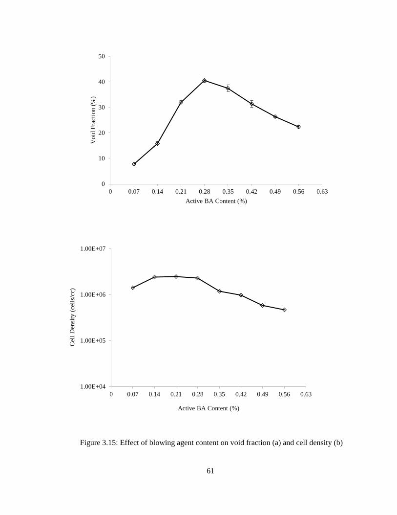
61
Figure 3.15: Effect of blowing agent content on void fraction (a) and cell density (b)
0
10
20
30
40
50
0 0.07 0.14 0.21 0.28 0.35 0.42 0.49 0.56 0.63
Vo
id F
ract
ion (
%)
Active BA Content (%)
1.00E+04
1.00E+05
1.00E+06
1.00E+07
0 0.07 0.14 0.21 0.28 0.35 0.42 0.49 0.56 0.63
Cel
l D
ensi
ty (
cell
s/cc
)
Active BA Content (%)

62
3.3.3 Effect of Extruder Screw Speed on Void Fraction and Cell Density
As per discussion in section 3.1.1 Screw Speed or Overall material flow rate is an important
parameter to process CBA blown PP foam in extrusion. In this set of experiments 0.28 wt% active
blowing agent is used in all cases. Screw Speed is increased from 10 RPM to 80 RPM with 10
RPM interval.
Figure 3.16 depicts the effect of screw speed on void fraction and cell density. At 10 RPM screw
speed the void fraction was 24% and cell density was 5x10⁵ cells/cc. As the RPM was increased,
both cell density and void fraction kept increasing in a good rate up to 30 RPM where the void
fraction becomes 30% and cell density become 2x10⁶. But from 30 RPM to 80 RPM the growth
of void fraction and cell density remained nominal. At 80 RPM screw speed, void fraction was
35% and cell density became 3x10⁶ cells/cc. This two-step increment can be more clearly seen in
the SEM images in Figure 3.17.
This two-step increment was caused by two governing forces in the system which control the
quality of the foam. From 10 RPM to 30 RPM, the main governing force was the gas loss in the
barrel. As the polymer-CBA mixture stayed long in the barrel, gas decomposed prematurely and
escaped through solid bed and the hopper. But at 30 RPM the screw speed required to prevent the
gas loss was achieved so gas loss in barrel didn’t remain the main governing force anymore. From
30 RPM to 80 RPM the main driving force was the die pressure. Increasing screw speed caused
slow increment of the pressure in the die (Figure 3.19). Lee et al. [59] have shown that with same
die geometry, increasing die pressure increases the pressure drop and higher pressure drop rate
promotes better void fraction and cell density. Similar phenomena can be found in the research of

63
Nam et al. [81] where void fraction increased slowly as they increased the screw speed in extrusion
foaming of PP.
Figure 3.16: Effect of Screw Speed on void fraction (a) and cell density (b)
0
10
20
30
40
0 10 20 30 40 50 60 70 80 90
Vo
id F
ract
ion (
%)
Screw Speed (RPM)
1.00E+04
1.00E+05
1.00E+06
1.00E+07
0 10 20 30 40 50 60 70 80 90
Cel
l D
ensi
ty (
cell
s/cc
)
Screw Speed (RPM)

64
10 RPM 20 RPM
30 RPM 40 RPM
50 RPM 60 RPM
70 RPM 80 RPM
Figure 3.17: SEM images of PP foams of different screw speed blown with Ecocell

65
Figure 3.18: Corresponding Die Pressure with the Screw Speed
3.3.4 Effect of Pressure Drop Rate on Void Fraction and Cell Density
Experiments done in section 3.3.3 have shown that increasing the extruder screw speed effectively
increases the quality of the foam. But increasing the screw speed also increases the overall flow
rate or throughput. This can be a big problem for manufacturing. Because every designed product
have some certain requirements based on its functionality or manufacturability. For example,
suppose in a PP foam extrusion process, each extrudate should be processed at the speed of 1 g/min
material flow rate because that is the ability of the downstream systems to cool the extrudates to
process further. But the upstream extruder can run at 80 RPM creating the throughput flow rate of
20 g/min. According the finding from section 3.3.3, the extruder should be run at 80 RPM to obtain
best quality foams, which will create a mess downstream. To solve this problem, industries usually
use multiple hole extrusion dies [82] which also solves the coupling effect with Residence time,
0
100
200
300
400
500
600
700
800
900
0 10 20 30 40 50 60 70 80 90
Die
Pre
ssure
(P
si)
Screw Speed (RPM)

66
as discussed in section 3.1.1. So for this specific case, a 20 hole die should be used to solve the
problem. But in foaming, using multiple holes of same dimensions may or may not be effective to
obtain good foams. More investigation is required to confirm the usage of multiple holes in
manufacturing of foamed PP.
In this set of experiment 4, 7 and 13 hole dies were used. All die holes are identical to the die hole
used in the previous experiments, which had 0.6 mm of diameter and L/D ratio of 6. Flow rate per
hole was varied between 0.2 g/min (3.8 GPa/s Pressure drop rate) to 2 g/min (41 GPa/s pressure
drop rate) by varying the screw speed from 5 RPM to 70 RPM. Active CBA content is kept
constant at 0.28 wt%.
Figure 3.19 (a) shows the effect of pressure drop rate on void fraction. For all cases the void
fraction started around 12% and as the pressure drop rate increased, it went up to around 30%. All
three trend lines followed the similar path found in previous experiment of screw speed variation
(Figure 3.16). So to confirm this finding, data points are plotted against total flow rate in Figure
3.19 (b). Figure 3.19 (b) followed the same trend found in Figure 3.16. The cell density for all 3
cases also showed the similar trend as the void fraction: starting around 1x10⁵ rapidly increased
up to 11 GPa/s pressure drop rate and then increased gradually to 3x10⁶ (Figure 3.20). Cell density
plotted against total flow rate followed the same trend found in Figure 3.16.
Figure 3.21 confirms that the foam quality will get better as the pressure drop rate is increased and
higher the number of holes better the foams if the flow rate per hole is kept constant. But there is
another issue with the results. If we look at the cell density graph, Theoretically Cell density should
be same for all trends for same pressure drop rate. And also same goes for Void fraction graph. As
the no. of hole increased, overall flow was also increased to keep the pressure drop rate constant.

67
But the upward trend of the trend line indicates that the residence time is affecting the results. The
experiments with residence time will confirm this finding.
Figure 3.19: Effect of Pressure Drop Rate (a) and overall flow rate (b) on void fraction
0
5
10
15
20
25
30
35
0 10 20 30 40 50
Vo
id F
ract
ion (
%)
Pressure Drop Rate (GPa/s)
4 Holes
7 Holes
13 Holes
0
5
10
15
20
25
30
35
0 5 10 15 20 25 30
Vo
id F
ract
ion (
%)
Total Flow Rate (g/min)
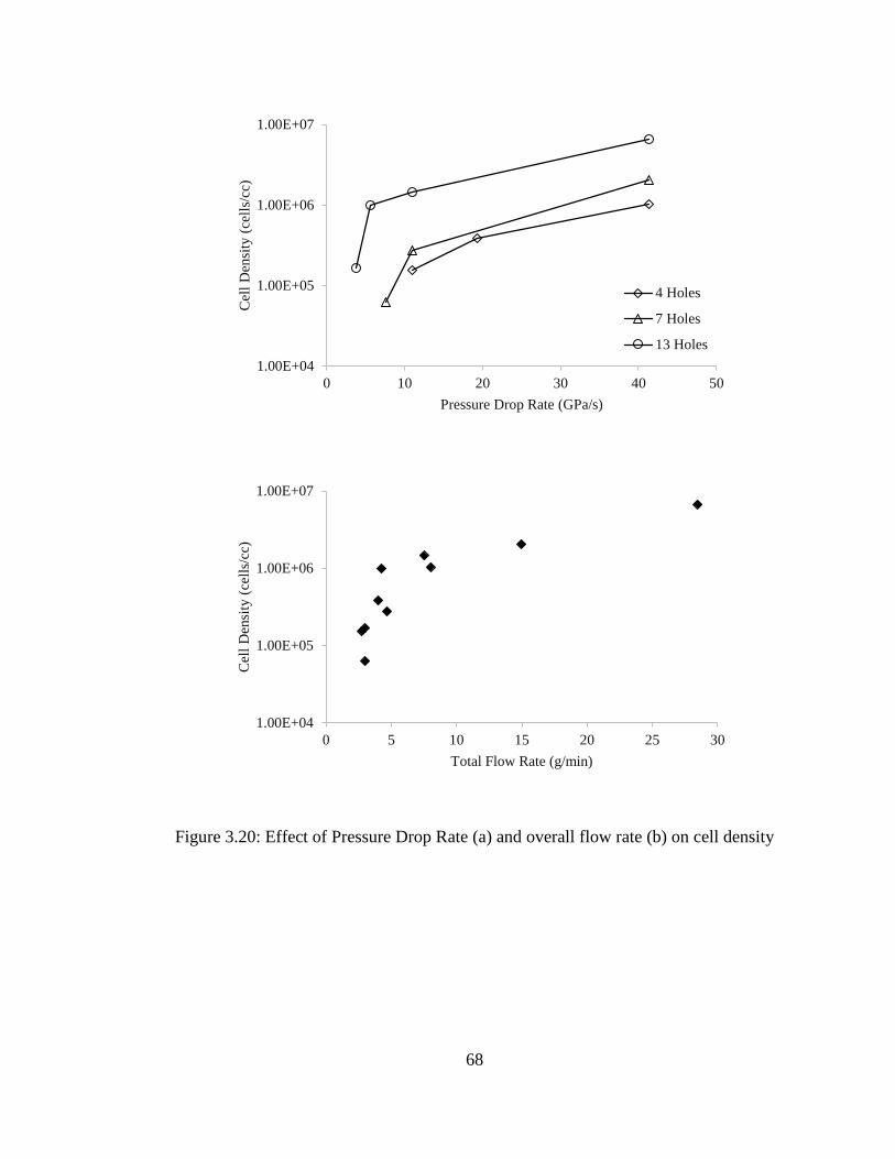
68
Figure 3.20: Effect of Pressure Drop Rate (a) and overall flow rate (b) on cell density
1.00E+04
1.00E+05
1.00E+06
1.00E+07
0 10 20 30 40 50
Cel
l D
ensi
ty (
cell
s/cc
)
Pressure Drop Rate (GPa/s)
4 Holes
7 Holes
13 Holes
1.00E+04
1.00E+05
1.00E+06
1.00E+07
0 5 10 15 20 25 30
Cel
l D
ensi
ty (
cell
s/cc
)
Total Flow Rate (g/min)

69
Pressure Drop Rate 11 GPa/s Pressure Drop Rate 41 GPa/s
4
Holes
Total Flow Rate 2.4 g/min Total Flow Rate 8.0 g/min
7
Holes
Total Flow Rate 4.2 g/min Total Flow Rate 14.0 g/min
13
Holes
Total Flow Rate 7.8 g/min Total Flow Rate 26.0 g/min
Figure 3.21: Comparative SEM images of PP foams of 2 different Pressure Drop Rate with 3
different die setup

70
3.3.5 Effect of Residence Time of the PP-CBA mixture inside the extrusion system on Void
Fraction and Cell Density
Last three set of experiments showed that, in low screw speed quality of foam deteriorates very
severely. According to the hypothesis presented in section 3.1.1, the core reason behind this
phenomena is the gas loss through the hopper as CBA decomposes prematurely staying too long
on the hot solid bed of the barrel. This set of experiment will investigate to find out the authenticity
of this hypothesis.
In this set of experiment 4, 7 and 13 hole dies were used. All die holes are identical to the die hole
used in the previous experiments, which had 0.6 mm of diameter and L/D ratio of 6. Residence
Time was varied between 3 mins to 29 mins by varying the screw speed from 5 RPM to 70 RPM.
Flow rate per hole was varied between 0.2 g/min (3.8 GPa/s Pressure drop rate) to 2 g/min (41
GPa/s pressure drop rate) for varying the RPM. Active CBA content is kept constant at 0.28 wt%.
Figure 3.22 shows the effect of residence time of PP-CBA mixture inside the system on void
fraction and cell density. Void fraction and Cell Density was highest when residence time was 3
mins with 33% and 6.67x10⁶ respectively and was lowest when residence time was 29 mins with
11% and 6.25x10⁴ respectively. Although 3 different die hole configurations has been used, it was
clear that as the residence time was reduced, the quality of foam improved dramatically.
The question of effectiveness of low residence time still remains as flow rate per hole varied while
changing the screw speed. So the data were rearranged and represented in Figure 3.23 & Figure
3.24 in terms of Pressure drop rate and the SEM images were presented in Figure 3.25. The trend

71
follows the same as Figure 3.22 confirming the authenticity of the hypothesis presented in section
3.1.1.
Figure 3.22: Effect of Residence Time on void fraction (a) and cell density (b) with different die
hole configuration
0
5
10
15
20
25
30
35
0 5 10 15 20 25 30 35
Vo
id F
ract
ion (
%)
Residence Time (min)
4 Holes
7 Holes
13 Holes
1.00E+04
1.00E+05
1.00E+06
1.00E+07
0 5 10 15 20 25 30 35
Cel
l D
ensi
ty (
cell
s/cc
)
Residence Time (min)
4 Holes
7 Holes
13 Holes

72
Figure 3.23: Effect of Residence Time on void fraction (a) and cell density (b) at 11 GPa/s
Pressure Drop Rate
0
5
10
15
20
25
30
5 10 15 20 25 30
Vo
id F
ract
ion (
%)
Residence Time (min)
Void Fraction (11GPa/s)
1.00E+04
1.00E+05
1.00E+06
1.00E+07
5 10 15 20 25 30
Cel
l D
ensi
ty (
cell
s/cc
)
Residence Time (min)
Cell Density (11GPa/s)

73
Figure 3.24: Effect of Residence Time on void fraction (a) and cell density (b) at 41 GPa/s
Pressure Drop Rate
20
25
30
35
2 3 4 5 6 7 8 9 10
Vo
id F
ract
ion (
%)
Residence Time (min)
Void Fraction (41GPa/s)
1.00E+05
1.00E+06
1.00E+07
2 3 4 5 6 7 8 9 10
Cel
l D
ensi
ty (
cell
s/cc
)
Residence Time (min)
Cell Density (41GPa/s)

74
Pressure Drop Rate 11 GPa/s Pressure Drop Rate 41 GPa/s
Residence Time 28 mins Residence Time 9 mins
Residence Time 20 mins Residence Time 5.5 mins
Residence Time 10 mins Residence Time 3 mins
Figure 3.25: Comparative SEM images of PP foams of 2 different Pressure Drop Rate with
different residence times

75
3.4 Summary & Conclusions
Experimental studies were carried out to manufacture polypropylene foams in high temperature
extrusion using chemical blowing agents. The experiments conducted in this study lead to the
following conclusions:
1. The basic strategies employed for the promotion of a good void fraction and fair cell
density with polypropylene materials was identified.
2. 33% void fraction and 6.67x10⁶ cells/cc cell density was achieved with 3 minutes of
residence time and 13 hole die configuration for 41 GPa/s pressure drop rate (2.0 g/min per
hole flow rate). Considering the flow rate used by industries and results from past
literatures, the obtained result can be called a big success.
3. CBA selection is the first most important step for extrusion foaming with CBAs. It should
be selected based on compatibility with the main polymer, low master-batch and most of
all, thermal requirement. For high temperature extrusion, CBAs with high decomposition
temperature and single step decomposition should be selected.
4. If the decomposition temperature of the CBA is set before it goes to the melt state they will
decompose in solid bed and make a way to escape through the hopper. So if possible, the
decomposition temperature of the CBA should be set at metering zone where PP and CBA
melts and mixes together. It will prevent the escape of the CBA gas due to temperature
setup.
5. From the previous literatures on blowing agents, we know that each polymer has different
solubility for different blowing agents and they can be saturated with that amount of gas.
But more gas causes more plasticization effect on polymers and if the blowing gas is
76
supplied from CBA, it also supplies the nucleating agents. In presence of high number
nucleating agents and plasticization effect high CBA content can cause very bad quality of
foams. So the optimum window should be found out for each Polymer-CBA combination
before using them for industrial production. In this specific case for PP-Ecocell
combination, 0.21-0.28 wt% seemed to be the best content percentage window for
industrial production.
6. Low residence time is the key factor for best quality foams. Low Residence time should be
maintained for high temperature extrusion foaming with CBAs.
7. Maximizing the pressure drop rate is another important issue, but production rate
requirement may be different as flow rate per hole will also change. In this case multiple
hole die can be used to compensate the production requirement. This multiple hole die
arrangement will not hamper the quality of the foam.

77
Chapter 4 Production of PP-Ecocell Foams with Nucleating Agents
in High Temperature Extrusion Foaming
4.1 Introduction
As discussed earlier, in high temperature extrusion foaming of PP with CBAs gas can escape
through hopper if processing speed is too low. Also selecting the right CBA for a specific process,
finding the right window of blowing agent content for that specific process and selecting the
number of hole based on flow rate requirement is also the key factor for producing good quality
polymeric foams with CBAs.
In this chapter a demonstration will be done to obtain good quality foams by introducing unique
nucleating agents and applying most favourable conditions found in Chapter 3. Also experiments
will be performed to investigate on the effects of combination of chemical blowing agent and
physical blowing agent on void fraction and cell density of extruded polypropylene foams.
4.1.1 Hypothesis
The main objective of this study is to apply the findings of the experiments done in chapter 3 with
nucleating agents and find out the outcome. Also the effect of the combination of CBA with PBA
on void fraction and cell density will be investigated.

78
There have been numerous studies done on heterogeneous nucleation and its effect on quality of
foams [85] [80] [11] [86]. From all studies it is clear that nucleating agents certainly improves the
quality of the foam where homogeneous nucleation is not effective. Although CBAs supply
nucleating agents along with gas, the size and content of the nucleating agent is unknown. Also
from chapter 3 it is known that supplying too much CBA will also deteriorate the quality of foam
due to plasticization effect and cell coalescence. Using low CBA content with additional
nucleating agent may be the answer to the problem. Medeiros et al. [87] found that based on
nucleation perspective, semi-crystalline talc has the best compatibility with PP. It also improve
mechanical properties of the PP composite [88] [89]. But if, both mechanical properties and
nucleation taken into account, Calcium Carbonate may be the best choice as nucleating agent [90]
[91] [92] [93] [94]. So in this study a semi-crystalline talc and three Calcium Carbonate will be
chosen as nucleating agent and the effect of nucleating agent content on quality of foam will be
investigated.
Lee et al. [59] found that N2 blowing agent with nucleating agents can produce very good quality
foams with good cell density. But in high temperature void fraction might not be good in N2 blown
foams as N2 already has high diffusivity and high temperature promotes diffusivity even more.
Wong et al. [83] and Di Maio et al. [84] found that in some specific applications a combination of
CO2 and N2 blowing agent can be very effective and can produce good quality foams. So a
combination of N2 with CO2 blowing gas may be an interesting thing to find out. But N2 producing
CBAs are toxic in nature. So the only way to supply the N2 blowing gas is by using it as a physical
blowing agent. So in this study CO2 will be supplied to the system with CBA (Ecocell) and N2 will
be injected to system by means of PBA. Some combinations will be tried to find out their effect
on the quality of the foams.

79
4.2 Experimental
4.2.1 Material Selection
4.2.1.1 Polymer Resin
Polypropylene
Polypropylene (PP) is a popular material in the plastic processing industry due to its enhanced
properties such as superior mechanical strength and higher service temperature. It is considered as
a promising candidate to replace polyethylene and polystyrene in many foaming applications.
The selected PP is a linear PP manufactured by ExxonMobil (PP3155), the same one used in
studies in Chapter 3. It is reported to have a Melt Flow Rate of 36 grams/10min and density of 0.9
g/cc [75]. This material is referred to as the neat PP. The melting point was not provided in the
material datasheet. So a DSC experiment has been conducted to find out its actual melting point
which is 166-170°C. Figure 3.2 illustrates the results of the DSC thermo-gram.
4.2.1.2 Chemical Blowing Agent
Ecocell L
Ecocell L is a CO2 based CBA, produced by Polyfil Corporation. It is endothermic in nature.
Chemically it is Sodium bicarbonate carried by a carrier polymer. The polymer carrier of this
blowing agent is polyethylene. This is the same CBA used for studies in Chapter 3. Its
decomposition temperature is around 200°C and it emits around 7% wt. gas when it reaches the

80
decomposition temperature. It has single step decomposition. Equation 3.1 shows the chemical
reaction happens when it reaches the decomposition temperature. Sodium Carbonate produced
from the reaction act as a nucleating agent in gas-polymer mixture which promotes heterogeneous
nucleation.
4.2.1.3 Physical Blowing Agent
Nitrogen Gas
It is widely accepted in the literature that nitrogen has superior nucleating power as a blowing
agent. Researchers have been able to obtain high cell density yet relatively low expansion ratio
foam using nitrogen with PP [59] [95]. Blowing agent used in this series of studies is 99.998%
purity nitrogen supplied by Linde Gas.
4.2.1.4 Nucleating Agent
Semi-crystalline Talc: Nicron 554
Nicron 554 is a high purity microcrystalline talc from Imerys Talc. It has high aspect ratio and
structure is lamellar in nature. It has a median diameter of 3.3 microns. Product datasheet shows
that it has 98% Hydrated Magnesium Silicate with 2% Dolomite and Chlorite [96].

81
Figure 4.1: SEM of Nicron 554 Semi-crystalline Talc
Precipitated Calcium Carbonate: Albacar 5970
Albacar 5970 is rosette shaped precipitated calcium carbonate (PCC) from Specialty Minerals. It
has a median diameter of 1.9 microns. Product datasheet shows that it has 98% Calcium Carbonate
with 2% Magnesium Carbonate, Iron Oxide and Moisture [97].
Figure 4.2: SEM of PCC Albacar 5970

82
Precipitated Calcium Carbonate: Multiflex-MM
Multiflex-MM is rhombohedral shaped precipitated calcium carbonate (PCC) from Specialty
Minerals. It has a median diameter of 0.07 microns. Product datasheet shows that it has 98%
Calcium Carbonate with 2% Magnesium Carbonate, Iron Oxide and Moisture [98].
Figure 4.3: SEM of PCC Multiflex-MM
Precipitated Calcium Carbonate: Thixo-Carb 500
Thixo-Carb 500 is cuboidal shaped precipitated calcium carbonate (PCC) from Specialty Minerals.
It has a median diameter of 0.15 microns. Product datasheet shows that it has 98% Calcium
Carbonate with 2% Magnesium Carbonate, Iron Oxide and Moisture [99].

83
Figure 4.4: SEM of PCC Thixo-Carb 500
4.2.2 Experimental Setup
4.2.2.1 Single Screw Extrusion System
Figure 4.5: Schematic of the Single Screw Extrusion System
Gas Injection
Pump

84
Figure 4.5 shows a schematic of the single screw extrusion system used in these experiments. It
was mainly consisted of a 0.75” single screw extruder and a gear pump. In order to enhance the
generation of a uniform polymer-gas mixture, a six-element static mixer with a diameter of 6.8
mm (Omega FMX-84441-S) as well as a heat exchanger containing homogenizing static mixers
(Labcore H-04669-12) were attached downstream to the extruder. The gear pump (Oerlikon
Barmag ZP504-0-IZ) was attached after the mixers to regulate the melt flow before it reached to
the die. The system arrangement is done to mimic the industrial extrusion system of Balta Group
of Belgium [76]. A 37 hole die is used at the exit of the system. Each die hole opening is cylindrical
in shape with diameter of 0.6 mm and length of 3.6 mm.
4.2.2.2 Thermal Zones of the Extrusion System
Zone Temperature (°C)
1 180
2 192
3 200
4 221
5 227
6 235
7 235
Figure 4.6: Thermal Zones of the Extrusion System
T1 T2 T3 T4 T5 T6 T7

85
4.2.2.3 Physical Blowing Agent Injection System
The physical blowing agent gas was injected with a high precision high pressure Teledyne ISCO
260D metering pump near the start of the metering zone of the extruder screw. Basically it is
consisted of a 260 mL cylinder and a control unit. It is also called syringe pump.
Figure 4.7: Teledyne ISCO 260D metering pump
4.2.3 Experimental Procedure
In this study, the system temperature profile is kept constant and similar to profile used in Chapter
3; for this instance the temperature profile is: 180°C-192°C-200°C-221°C-227°C-235°C from
feeder to die.
Before PP pellets were fed through hopper, they were dry blended with the CBAs and Nucleating
agents based on their active concentration. Four different kinds of nucleating agents were used in

86
these experiments. For PBA injection, a 0.05 restrictor is used and flow rate is varied from 0.032
mL/min to 0.28 mL/min. The speed for the extruder motor and the gear pump motor was
maintained at 60 RPM and 16 RPM respectively. A 37 hole die was used to maintain 0.6 g/min
flow rate per hole and 11 GPa/s pressure drop rate with shorter residence time/ higher overall
throughput. The foam samples were randomly selected at each set of processing conditions and
were subsequently characterized.
4.2.4 Sample Characterization & Analysis
4.2.4.1 Volume Expansion Ratio & Void Fraction
The expansion ratio of foam samples can be calculated by taking the density ratio between foamed
and un-foamed polymer, where the density of each is measured with the water displacement
method outlined in ASTM D792. The volume expansion ratio (VER) of a foam sample can be
calculated as the ratio of the bulk density of pure material to the bulk density of the foam sample
using Equation 2.14. Expansion Ratio can be converted to Void Fraction using Equation 2.15.
4.2.4.2 SEM Imaging and Foam Cell Density Characterization
A Scanning Electron Microscope (JEOL JMS6060) was used to examine the cellular morphology
of collected samples. Samples were freeze fractured with liquid nitrogen to expose the cross-
section. The fractured surfaces were then sputter-coated with a thin layer of platinum and then
observed using SEM. Area and the number of cells in the area were calculated using the SEM
images using the image processing software- ImageJ V.2.8, NIH of USA. Cell density was
calculated using Equation 2.16. Three samples were characterized for each set of processing

87
conditions, and an average value for each processing condition was reported. The cell density and
void fraction of three tested samples at each condition were within 10% of experimental error.
4.3 Results & Discussions
4.3.1 Effect of Different Types of Nucleating Agent on Void Fraction and Cell Density
This set experiment is done to find out the better type of nucleating agent for high temperature
extrusion with CBA. As per hypothesis discussed in section 4.1.1, both semi-crystalline talc and
calcium carbonate should be good in this application. So as a semi-crystalline talc ‘Nicron’ and as
calcium carbonate ‘Multiflex’ is picked.
In this set of experiments CBA content is varied from 0.07 wt% to 0.28 wt% with interval of 0.07.
In the meantime the Nucleating Agent content is fixed at 0.5 wt%. Pressure drop rate is maintained
11 GPa/s with the screw speed 60 RPM. Residence time was 4.5 mins for each point.
Figure 4.13 shows that both nucleating agents gave similar trend in terms of void fraction starting
from 5% region, going up to 30% region. Slope of both the curves are steeper than no nucleating
agent curve. But when we look into the cell density curve and SEM images in Figure 4.14, it shows
that talc has a reverse effect, rather than improving the cell density like calcium carbonate it
reduces the cell density. The main reason behind this is compatibility. In high temperature
extrusion, calcium carbonate is more compatible as a nucleating agent with Ecocell than talc.
Another reason behind this phenomena may be the size of nucleating agent. Particle size of Nicron
is 3.3 micron and 0.07 micron for Multiflex, but particle size of the CBA by-product nucleating

88
agent is unknown. In same amount of mass, number of the particles is higher for smaller particles
than bigger particles. Therefore, according to the heterogeneous nucleation theory, the lower the
size of the particle more the number of cells. This explains that, the particle size of the built in
CBA nucleating agent is in between 0.07 microns to 3.3 microns.
Figure 4.8: Void fraction & Cell Density of different nucleating agents
0
5
10
15
20
25
30
35
0 0.07 0.14 0.21 0.28 0.35
Void
Fra
ctio
n (
%)
Active CBA Content (%)
Pure CBA
0.5% Talc
0.5% Multiflex
1.00E+05
1.00E+06
1.00E+07
0 0.07 0.14 0.21 0.28 0.35
Cel
l D
ensi
ty (
cell
s/cc
)
Active CBA Content (%)
Pure CBA
0.5% Talc
0.5% Multiflex
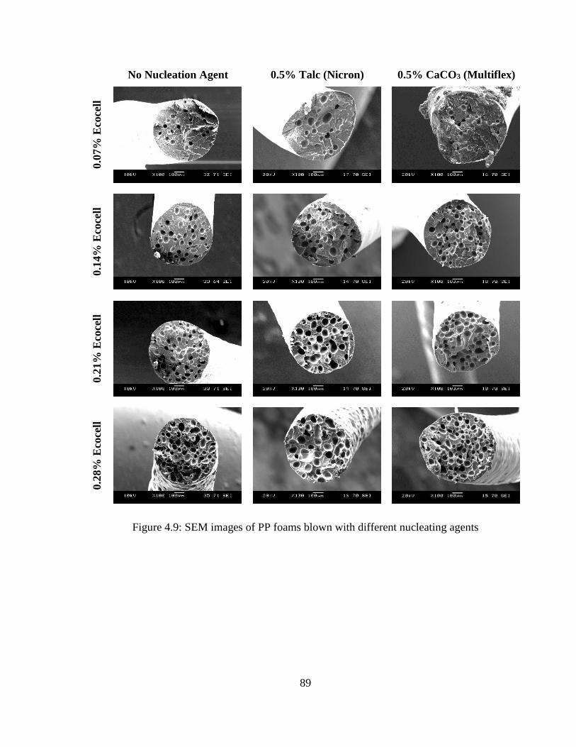
89
No Nucleation Agent 0.5% Talc (Nicron) 0.5% CaCO3 (Multiflex)
0.0
7%
Eco
cell
0.1
4%
Eco
cell
0.2
1%
Eco
cell
0.2
8%
Eco
cell
Figure 4.9: SEM images of PP foams blown with different nucleating agents

90
4.3.2 Effect of Nucleating Agent Content on Void Fraction and Cell Density
Last set of experiments showed that calcium carbonates are better nucleating agents over talc for
high temperature extrusion foaming with CBA. So in set of experiments 3 types of calcium
carbonate was chosen based on their particle size. Average particle size of Albacar is 1.9 micron,
Thixo-Carb is 0.15 micron and Multiflex is 0.07 micron.
In this set of experiment Nucleating Agent content is varied from 0.5 wt% to 3.5 wt% with interval
of 1. In the meantime the CBA content is fixed at 0.21 wt%. Pressure drop rate is kept at 11 GPa/s
with the screw speed 60 RPM. Residence time was 4.5 mins for each point.
Figure 4.15 portrays the effect of the nucleating agent on void fraction and cell density. In terms
of void fraction there is not much of a difference between the three lines, starting around 20% void
fraction and ending 30% increasing gradually. Which is expected, because no additional gas is
supplied and adding nucleating agents increases the cell numbers and these increased number. And
from Lee’s [95] work it is known that increased number of cells helps to minimize the gas loss
through diffusion. On the other hand from cell density graph and SEM images in Figure 4.16 it is
clear that Multiflex is better nucleating agent than the other two. Its cell density started from
3.25x10⁶ then gradually increasing to 4.5x10⁶.
From the obtained results it is clear that finer the particle of the nucleating agents the more the cell
density thus better quality of the foam. But it should also be mentioned that the nucleating agents
were mixed by dry blending. Without proper feeding, the fine particles may fall in the solid bed of
extruder before properly mixed in extruder and the continuity of the content will be hampered. So

91
it is better to compound the agent with polymer resin before processing with the manufacturing
extruder.
Figure 4.10: Effect of nucleating agent content on void fraction (a) and cell density (b)
0
5
10
15
20
25
30
35
0 1 2 3 4
Void
Fra
ctio
n (
%)
Nucleating Agent Content (%)
Albacar
Thixo-Carb
Multiflex
1.00E+05
1.00E+06
1.00E+07
0 1 2 3 4
Cel
l D
ensi
ty (
cell
/cc)
Nucleating Agent Content (%)
Albacar
Thixo-Carb
Multiflex
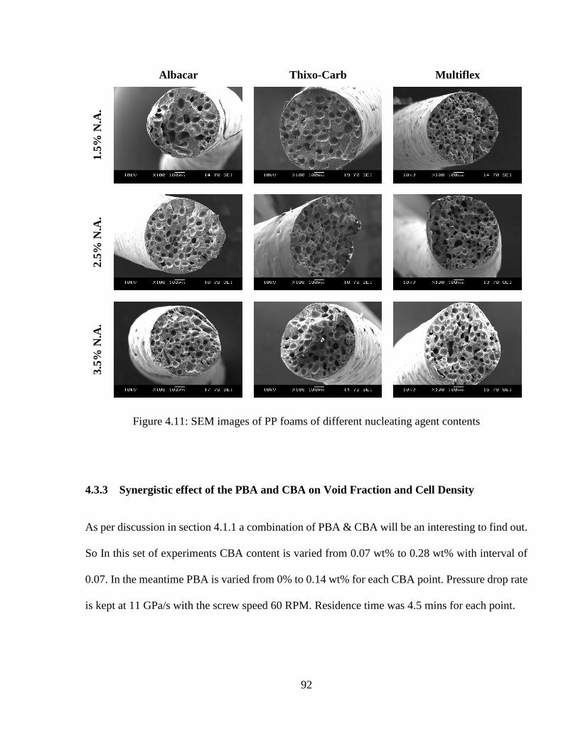
92
Albacar Thixo-Carb Multiflex
1.5
% N
.A.
2.5
% N
.A.
3.5
% N
.A.
Figure 4.11: SEM images of PP foams of different nucleating agent contents
4.3.3 Synergistic effect of the PBA and CBA on Void Fraction and Cell Density
As per discussion in section 4.1.1 a combination of PBA & CBA will be an interesting to find out.
So In this set of experiments CBA content is varied from 0.07 wt% to 0.28 wt% with interval of
0.07. In the meantime PBA is varied from 0% to 0.14 wt% for each CBA point. Pressure drop rate
is kept at 11 GPa/s with the screw speed 60 RPM. Residence time was 4.5 mins for each point.

93
Figure 4.12 shows the synergistic effect of PBA content and CBA content on void fraction and
cell density. Pure CBA content trend showed the similar trend found in Chapter 3. But when PBA
is added to the mix the trend changed drastically. Before analyzing the reason behind this
phenomena, it’s better to have a look at Figure 4.10 where results are obtained with pure PBA and
without any nucleating agent.
Figure 4.12: Void Fraction & SEM of PBA blown foams
From Figure 4.10 it is clear that in this specific set of experiment, with more PBA, void fraction is
increasing but quality of foam is very poor. Even more the PBA is added, more the skin of the
extrudate became rough. Maybe the most acceptable reason behind this rough skin is,
crystallization of the skin while the outward diffusion of the N2 gas was taking place. N2 has high
diffusivity and in high temperature, the diffusivity becomes higher.
0
10
20
30
40
50
60
0 0.07 0.14 0.21 0.28 0.35
Vo
id F
ract
ion (
%)
Active PBA Content (%)

94
Figure 4.13: Effect of N2 PBA and CBA content on void fraction (a) and cell density (b)
0
5
10
15
20
25
30
35
0 0.07 0.14 0.21 0.28 0.35
Void
Fra
ctio
n (
%)
Active CBA Content (%)
0.00% N2
0.07% N2
0.14% N2
1.00E+05
1.00E+06
1.00E+07
0 0.07 0.14 0.21 0.28 0.35
Cel
l D
ensi
ty (
cell
s/cc
)
Active CBA Content (%)
0.00% N2
0.07% N2
0.14% N2

95
0.00% N2 PBA 0.07% N2 PBA 0.14% N2 PBA
0.0
7%
Eco
cell
0.1
4%
Eco
cell
0.2
1%
Eco
cell
0.2
8%
Eco
cell
Figure 4.14: Comparative SEM images of PP foams with different PBA & CBA contents
The combined effect of the PBA & CBA can be explained more clearly with the SEM images in
Figure 4.11. In the cell density graph, except 0.07%CBA+0.00%PBA point all other points
remained in the same zone, which proves that the PBA didn’t contribute to the new cell nucleation.
96
Furthermore the void fraction graph shows that when the more PBA was added, they acted more
like an additional blowing agent. At total blowing content of 0.28 the best foams were obtained.
But, after crossing that point cell coalescence and skin roughening started to take place depleting
the quality of the foam. So in high temperature extrusion, a combination of PBA and CBA is not
a viable idea.
4.4 Summary & Conclusions
Experimental studies were carried out to manufacture polypropylene foams in high temperature
extrusion using Ecocell chemical blowing agent with nucleating agents. The experiments
conducted in this study lead to the following conclusions:
1. Some basic strategies were employed like, addition of PBA and Nucleating agents and their
effect on quality of foam was investigated.
2. A combination of CBA & PBA is not a viable option to obtain good quality foams,
especially in high temperature foam extrusion.
3. Addition of Nucleating Agents is a good option if the nucleating agent is compatible with
the used CBA. Calcium Carbonated seemed to be a very good match for Ecocell CBA.
4. Quality of foam went up as finer nucleating agents were used. But material preparation is
a very important step for nano-level nucleating agents. Finer nucleating agents are
recommended.

97
Chapter 5 Conclusion
5.1 Summary
In order to fulfill the rapidly growing demand for polymeric foams, new innovative classes of
foams and their manufacturing processes are constantly being researched on. The manufacturing
of polymeric foam in high temperature extrusion with CBAs is a promising concept as foaming
improves a number of a material’s property including toughness, fatigue life, and light weight;
most importantly, it reduces material consumption significantly. Moreover, this technology is
instantly transferable to an industrial production line without any additional apparatus.
Unfortunately, there are only a few research has been done on high temperature processing as the
quality of foam deteriorates in that condition. But industrial setup demands high temperature
processing and this problem can be solved using CBAs. This thesis investigated strategies to
produce good quality foams with CBAs in high temperature processing and demonstrated the
feasibility of producing foams in an industrial production line.
5.2 Key Contributions
This study lead to the following key contributions:
1. The effects of different chemical blowing agent, blowing agent content, extruder screw
speed, pressure drop rate and residence time on the foaming behavior of polypropylene are
investigated and compared. It is shown that good quality PP foam can be best obtained by

98
single step high decomposition temperature CBA, in a certain blowing agent content
window, high pressure drop rate and low residence time. The study not only pinpoints a
strategy for producing good quality foam, but also offers quantitative comparison in terms
of the effect that each parameter has on the foaming behavior. A systematic foaming study
like this has not been previously reported, especially for producing foams with CBA in
high temperature extrusion.
2. After optimizing the parameters, effect of a combination of PBA-CBA and effect of
nucleating agents was investigated. It turned out that a combination of PBA-CBA is not a
good idea in high temperature extrusion. On the other hand, good quality PP foams can be
obtained by using higher nucleating agent content but the nucleating agent should be
compatible with corresponding CBA and of finer in particle size.
5.3 Recommended Future Works
From this study following future works can be recommended:
1. Temperature profile of the extrusion system was kept unchanged. But the decomposition
of CBA can triggered by controlling the temperature profile. There is a huge scope of
investigating different temperature profiles to find out optimum output for each type of
CBAs.
2. N2 gas emitting CBAs were not taken into account due to toxicity issue, but they are
exothermic in nature, so experiments with these CBAs will also be an interesting thing to
find out.

99
3. Although this study is based on extrusion, in some specific application injection molding
also requires high temperature processing. It will be interesting to find out the outcome by
applying the finding from this study to injection molding production process.
4. Most of all, this study will be successful if the outcomes of this study is implemented in an
actual industrial production line.

100
References
[1] C. Park, D. Baldwin and N. Suh, "Effect of the pressure drop rate on cell nucleation in
continuous processing of microcellular polymers," Polymer Engineering & Science, vol.
35(5), pp. 432-440, 1995.
[2] L. Matuana, C. Park and J. Balatinecz, "Structures and mechanical properties of
microcellular foamed polyvinyl chloride," Cellular Polymers, vol. 17(1), pp. 1-16, 1998.
[3] W. Michaeli and et.al., "Improving the impact behaviour of structural foams," Cellular
Polymers, vol. 28(4), pp. 269-287, 2009.
[4] C. Park and N. Suh, "Rapid heating for microcellular nucleation in a polymer melt.," in
Society of Polymer Engineering Annual Technical Conference, Detroit, Michigan, 1992.
[5] K. Seeler and V. Kumar, "Tension-tension fatigue of microcellular polycarbonate: initial
results," Journal of Reinforced Plastics and Composites, vol. 12, pp. 359-376, 1993.
101
[6] Y. Kim and et.al., "Studies of the Variation in the Dielectric Constant and Unique
Behaviors with Changes in the Foaming Ratio of the Microcellular Foaming Process,"
Polymer-Plastics Technology and Engineering, vol. 50(8), pp. 762-767, 2011.
[7] L. Glicksman, "4.10 S Foams and Cellular Materials: Thermal and Mechanical
Properties.," in Notes from MIT Summer Program, Cambridge, MA, 1992.
[8] K. Suh and et.al., "Lightweight cellular plastics.," Advanced Materials, vol. 12(23), pp.
1779-1789, 2000.
[9] Ceresana Inc., "Market Study: Polypropylene (3rd edition)," December 2014. [Online].
Available: http://www.ceresana.com/en/market-studies/plastics/polypropylene/.
[10] C. Park, A. Behravesh and R. Venter, "Low-Density, Microcellular Foam Processing in
Extrusion Using CO2," Polymer Engineering and Science, vol. 38, no. 11, pp. 1812-1823,
1998.
[11] W. Kaewmesri, P. Lee, C. Park and J. Pumchusak, "Effects of CO2 and Talc Contents on
Foaming Behavior of Recyclable High-Melt-Strength PP," Journal of Cellular Plastics,
vol. 42, no. 5, pp. 405-428, 2006.
102
[12] C. Park and N. Suh, "Filamentary Extrusion of Microcellular Polymers Using a Rapid
Decompressive Element," Polymer Engineering and Science, vol. 36, no. 1, pp. 34-48,
1996.
[13] R. Gendron, Thermoplastic foam processing : principles and development, CRC press,
2005.
[14] Y. Sato, K. Fujiwara, T. Takikawa, Sumarno, S. Takishima and H. Masuoka, "Solubilities
and diffusion coefficients of carbon dioxide and nitrogen in polypropylene, high-density
polyethylene, and polystyrene under high pressures and temperatures," Fluid Phase
Equilibria, vol. 162, no. 1-2, p. 261–276, 1999.
[15] M. Lee, C. Tzoganakis and C. Park, "Effects of Supercritical CO2 on the Viscosity and
Morphology of Polymer Blends," Advances in Polymer Technology, vol. 19, pp. 300-311,
2000.
[16] D. M. Newitt and K. E. Weale, "Solution and diffusion of gases in polystyrene at high
pressures.," Journal of the Chemical Society, pp. 1541-1549, 1948.
[17] M. M. Hasan, Y. G. Li, G. Li, C. B. Park and P. Chen, "Determination of Solubilities of
CO2 in Linear and Branched Polypropylene Using a Magnetic Suspension Balance and a
PVT Apparatus," J. Chem. Eng. Data, vol. 55, no. 11, p. 4885–4895, 2010.

103
[18] G. Li and C. Park, "A New Crystallization Kinetics Study of Polycarbonate Under High-
Pressure Carbon Dioxide and Various Crystallinization Temperatures by Using Magnetic
Suspension Balance," Journal of Applied Polymer Science, vol. 118, no. 5, p. 2898–2903,
2010.
[19] G. Matthews, Polymer Mixing Technology, London: Applied Science Publishers, 1982.
[20] G. Choudalakis, "Permeability of polymer/clay nanocomposites: A review," European
Polymer Journal, vol. 45, no. 4, p. 967–984, 2009.
[21] C. Park and N. Suh, "Rapid Polymer/Gas Solution Formation for Continuous Processing
of Microcellular Plastics," Journal of Manufacturing Science and Engineering, vol. 118,
no. 4, pp. 639-645, 1996.
[22] C. Park, Class notes from Manufacturing of Cellular and Microcellular Polymers:
Continuous Microcellular Processing, Toronto: University of Toronto, 2013.
[23] X. Chen, J. J. Feng and C. A. Bertelo, "Plasticization effects on bubble growth during
polymer foaming," Polymer Engineering & Science, vol. 46, no. 1, p. 97–107, 2006.
[24] M. Xu, M.ASc. Thesis: Development of Lightweight, Biodegradable Plastic Foam Fibres
with Poly (Lactic) Acid-Clay Nanocomposites, Toronto: University of Toronto, 2013.
104
[25] A. Doolittle, The technology of solvents and plasticizers, New York: Wiley, 1954.
[26] J. Gibbs, The Scientific Papers of J. Willard Gibbs. Vol. 1, New York: Dover Publications
Inc., 1961.
[27] S. D. Lubetkin, "Why is it much easier to nucleate gas bubbles than theory predicts?,"
Langmuir, vol. 19, no. 7, p. 2575–2587, 2003.
[28] A. S. Tucker and C. A. Ward, "Critical state of bubbles in liquid‐gas solutions," Journal
of Applied Physics , vol. 46, no. 11, pp. 4801-4808, 1975.
[29] H. Park, C. B. Park, C. Tzoganakis, K. H. Tan and P. Chen, "Surface Tension
Measurement of Polystyrene Melts in Supercritical Carbon Dioxide," Ind. Eng. Chem.
Res., vol. 45, no. 5, p. 1650–1658, 2006.
[30] J. C. Fisher, "The Fracture of Liquids," Journal of Applied Physics, vol. 19, no. 11, p.
1062, 1948.
[31] C. A. Ward and E. Levart, "Conditions for stability of bubble nuclei in solid surfaces
contacting a liquid‐gas solution," Journal of Applied Physics, vol. 56, no. 2, p. 491, 1984.

105
[32] M.-C. Guo, Y.-C. Peng, Y.-B. Cai and W.-G. Zhou, "Effect of shear energy upon bubble
nucleation under shear flow field," Journal of Materials Science, vol. 39, no. 11, pp. 3805-
3807, 2004.
[33] S. N. Leung, A. Wong, L. C. Wang and C. B. Park, "Mechanism of extensional stress-
induced cell formation in polymeric foaming processes with the presence of nucleating
agents," The Journal of Supercritical Fluids, vol. 63, p. 187–198, 2012.
[34] P. Spitael, C. W. Macosko and R. B. McClurg, "Block Copolymer Micelles for Nucleation
of Microcellular Thermoplastic Foams," Macromolecules, vol. 37, no. 18, p. 6874–6882,
2004.
[35] J. Stange and H. Münstedt, "Rheological properties and foaming behavior of
polypropylenes with different molecular structures," Journal of Rheology, vol. 50, no. 6,
p. 907, 2006.
[36] C. Hea, S. Costeuxa, P. Wood-Adamsb and J. M. Dealyc, "Molecular structure of high
melt strength polypropylene and its application to polymer design," Polymer, vol. 44, no.
23, p. 7181–7188, 2003.
[37] C. B. Park, Cheung and L. K., "A study of cell nucleation in the extrusion of polypropylene
foams," Polymer Engineering and Science, vol. 37, no. 1, pp. 1-10, 1997.

106
[38] H. E. Naguib, C. B. Park and N. Reichelt, "Fundamental foaming mechanisms governing
the volume expansion of extruded polypropylene foams," Journal of Applied Polymer
Science, vol. 91, no. 4, p. 2661–2668, 2004.
[39] S. Lee, C. Park and N. Ramesh, Polymeric Foams: Science and Technology, New York:
CRC Press, 2006.
[40] G. C. Munters and J. G. Tandberg, "Heat insulation". USA Patent 2,023,204, 3 December
1935.
[41] Wikipedia, "Montreal Protocol," 2 July 2015. [Online]. Available:
https://en.wikipedia.org/wiki/Montreal_Protocol.
[42] K. Majithiya, M.A.Sc. Thesis: The effect of molecular weight on polypropylene foaming,
Toronto: Universityof Toronto, 2012.
[43] J. Throne, Thermoplastic foam extrusion: an introduction, Ohio: Hanser Gardner
Publications Inc., 2004.
[44] D. Eaves, Handbook of Polymer Foams, Rapra Technology Limited, 2004.

107
[45] X. Qin, M. R. Thompson and A. N. Hrymak, "Rheological Comparison of Chemical and
Physical Blowing Agents in a Thermoplastic Polyolefin," Ind. Eng. Chem. Res., vol. 45,
no. 8, p. 2734–2740, 2006.
[46] A. Peterlin, "Plastic deformation of crystalline polymers," Polymer Engineering &
Science, vol. 17, no. 3, pp. 183-193, 1977.
[47] M. Volmer and M. Marder, "Zur theorie der linearen kristallisations-geschwindigkeit
unterkuhlter schemlzen und unterkuhlter fester modifikationen," Z. Phys. Chem. A, vol.
154, p. 97, 1931.
[48] F. P. Price, "Nucleation in polymer crystallization," in Nucleation, New York, Marcel
Dekker, 1969, pp. 405-488.
[49] D. Turnbull and J. C. Fisher, "Rate of Nucleation in Condensed Systems," J. Chem. Phys.,
vol. 17, no. 1, p. 71, 1949.
[50] M. L. Williams, R. F. Landel and J. D. Ferry, "The Temperature Dependence of Relaxation
Mechanisms in Amorphous Polymers and Other Glass-forming Liquids," J. Am. Chem.
Soc., vol. 77, no. 14, p. 3701–3707, 1955.

108
[51] J. I. Lauritzen and J. D. Hoffman, "Extension of theory of growth of chain‐folded polymer
crystals to large undercoolings," Journal of Applied Physics, vol. 44, no. 10, p. 4340, 1973.
[52] X. Xu, C. Park, D. Xu and R. Pop-Iliev, "Effect of Die Geometry on Cell Nucleation of
PS Foams Blown with CO2," Polymer Engineering and Science, vol. 43, no. 7, pp. 1378-
1390, 2003.
[53] W. Michaeli, Extrusion Dies for Plastics and Rubber, Carl Hanser Verlag GmbH & Co.
KG, 2003 .
[54] P. C. Lee, W. Kaewmesri, J. Wang, C. B. Park, J. Pumchusak, R. Folland and A. Praller,
"Effect of die geometry on foaming behaviors of high-melt-strength polypropylene with
CO2," Journal of Applied Polymer Science, vol. 109, no. 5, p. 3122–3132, 2008.
[55] K. C. Frisch and J. H. Saunders, Plastic foams. Vol. 1, M. Dekker, 1972.
[56] D. B. Todd, "Residence time distribution in twin‐screw extruders.," Polymer Engineering
& Science, vol. 15, no. 6, pp. 437-443, 1975.
[57] D. Wolf and D. H. White, "Experimental study of the residence time distribution in
plasticating screw extruders," AIChE Journal, vol. 22, no. 1, pp. 122-131, 1976.

109
[58] V. Nagy and L. M. Vas, "Pore Characteristic Determination with Mercury Porosimetry in
Polyester Staple Yarns," Fibres & Textiles in Eastern Europe, vol. 51, no. 3, pp. 21-26,
2005.
[59] J. Lee and C. Park, "Use of Nitrogen as a Blowing Agent for the Production of Fine-Celled
High-Density HDPE Foams," Macromolecular Materials & Engineering, vol. 45, no. 23,
pp. 1233-1244, 2006.
[60] European Union, "COMMISSION DIRECTIVE 2004/1/EC amending Directive
2002/72/EC as regards the suspension of the use of azodicarbonamide as blowing agent,"
in Official Journal of the European Union, 2004, pp. 45-46.
[61] World Health Organization, "Concise International Chemical Assessment Document 16:
AZODICARBONAMIDE," World Health Organization, Geneva, 1999.
[62] A. Behravesh, C. Park, L. Cheung and R. Venter, "Extrusion of Polypropylene Foams with
Hydrocerol and Isopentane," Journal of Vinyl and Additive Technology, vol. 2, no. 4, pp.
349-357, 1996.
[63] Clariant Inc., "Hydrocerol," [Online]. Available: http://www.clariant-
polska.pl/en/products/masterbatches/hydrocerol.

110
[64] C. Blaney, G. K. Jones and D. G. Bland, "Polymeric materials providing improved infrared
emissivity". USA Patent US20140271754 A1, 18 September 2014.
[65] P. Xing, "Polyethylene foam and multilayered structure including the same". USA Patent
US20140272229 A1, 18 September 2014.
[66] Polyfil Corp., "Polyfil Ecocell," [Online]. Available:
http://www.polyfilcorp.com/ecocell.htm.
[67] B. Mussig and S. Kammerer, "Monoaxially oriented polypropylene film with high
transverse tear propagation resistance". USA Patent US20080020191 A1, 24 January
2008.
[68] C. Cavalieri and F. Pradella, "Process for the Nucleation of Polypropylene Resins". USA
Patent US20100160540 A1, 24 June 2010.
[69] Adeka Corp., "Adeka Palmarole," [Online]. Available: http://www.adeka-
palmarole.com/.
[70] Reedy Chemicals, "Safoam," [Online]. Available:
http://www.reedychemicalfoam.com/products/safoam.php.

111
[71] A. H. Behravesh, C. B. Park and R. D. Venter, "Challenge to the production of low-
density, fine-cell HDPE foams using CO2," Cellular polymers, vol. 17, no. 5, pp. 309-
326, 1998.
[72] S.-T. Lee and N. S. Ramesh, "Gas loss during foam sheet formation," Advances in Polymer
Technology, vol. 15, no. 4, p. 297–305, 1996.
[73] K.-C. Corporation, "Nonwoven fabric laminates". USA Patent US5188885 A, 23 February
1993.
[74] P. H. Nam, P. Maiti, M. Okamoto and T. Kataka, "Foam processing and cellular structure
of polypropylene/clay nanocomposites," Polymer Engineering and Science, vol. 42, no. 9,
p. 1907, 2002.
[75] E. Chemical, "ExxonMobil PP3155 Polypropylene Homopolymer," [Online]. Available:
http://exxonmobilchemical.ides.com/en-
US/ds244064/ExxonMobil%E2%84%A2%20PP3155.aspx?I=82928&U=0.
[76] Balta Group, "Balta Group: Inspiring Floors," [Online]. Available:
http://www.baltagroup.com/.

112
[77] T. P. &. G. Company, "Extrusion process for thermoplastic resin composition for fabric
fibers with exceptional strength and good elasticity". USA Patent US4323534 A, 17
December 1979.
[78] A. Bos, I. G. M. Pünt, M. Wessling and H. Strathmann, "CO2 induced plasticization
phenomena in glassy polymers," Journal of Membrane Science, vol. 155, no. 1, pp. 67-
78, 1999.
[79] S. K. Goel and E. J. Beckman, "Generation of microcellular polymeric foams using
supercritical carbon dioxide. I: Effect of pressure and temperature on nucleation," Polymer
Engineering & Science, vol. 34, no. 14, pp. 1137-1147, 1994.
[80] H. Naguib, C. Park and P. Lee, "Effect of Talc Content on the Volume Expansion Ratio
of Extruded PP Foams," Journal of Cellular Plastics, vol. 39, no. 6, pp. 499-511, 2003.
[81] G. J. Nam, J. H. Yoo and J. W. Lee, "Effect of long‐chain branches of polypropylene on
rheological properties and foam‐extrusion performances," Journal of Applied Polymer
Science, vol. 96, no. 5, pp. 1793-1800, 2005.
[82] E. Moczik, "Multiple hole extrusion die". USA Patent US2673645 A, 11 June 1951.

113
[83] C. Park, L. Cheung and S.-W. Song, "The Effect of Talc on Cell Nucleation in Extrusion
Foam Processing of Polypropylene with CO2 and Isopentane," Cellular Polymers, vol. 17,
no. 4, pp. 221-251, 1998.
[84] H. Naguib, C. Park, P. Lee and D. Xu, "A Study on the Foaming Behaviors of PP Resins
with Talc as Nucleating Agent," Journal of Polymer Engineering, vol. 26, no. 6, pp. 565-
587, 2006.
[85] E. d. Medeiros, R. Tocchetto, L. d. Carvalho, I. Santos and A. Souza, "Nucleating effect
and dynamic crystallization of a poly (propylene)/talc system," Journal of Thermal
Analysis and Calorimetry, vol. 66, no. 2, pp. 523-531, 2001.
[86] S. Karrad, J.-M. L. Cuesta and A. Crespy, "Influence of a fine talc on the properties of
composites with high density polyethylene and polyethylene/polystyrene blends," Journal
of Materials Science, vol. 33, no. 2, pp. 453-461, 1998.
[87] Y. Zhou and P. K. Mallick, "Effects of temperature and strain rate on the tensile behavior
of unfilled and talc-filled polypropylene. Part II: Constitutive equation," Polymer
Engineering & Science, vol. 42, no. 12, p. 2461–2470, 2002.
114
[88] Z. Zhang, Y. Tao, Z. Yang and K. Mai, "Preparation and characteristics of nano-CaCO3
supported β-nucleating agent of polypropylene," European Polymer Journal, vol. 44, no.
7, p. 1955–1961, 2008.
[89] C.-M. Chana, J. Wub, J.-X. Lia and Y.-K. Cheunga, "Polypropylene/calcium carbonate
nanocomposites," Polymer, vol. 43, no. 10, p. 2981–2992, 2002.
[90] W. Zhu, G. Zhang, J. Yu and G. Dai, "Crystallization behavior and mechanical properties
of polypropylene copolymer by in situ copolymerization with a nucleating agent and/or
nano-calcium carbonate," Journal of Applied Polymer Science, vol. 91, no. 1, p. 431–438,
2004.
[91] W. Zuiderduin, C. Westzaan, J. Huétink and R. Gaymans, "Toughening of polypropylene
with calcium carbonate particles," Polymer, vol. 44, no. 1, p. 261–275, 2003.
[92] Q.-X. Zhanga, Z.-Z. Yua, X.-L. Xiea and Y.-W. Maia, "Crystallization and impact energy
of polypropylene/CaCO3 nanocomposites with nonionic modifier," Polymer, vol. 45, no.
17, p. 5985–5994, 2004.
[93] A. Wong, L. Mark, M. Hasan and C. Park, "The Synergy of Supercritical CO2 and
Supercritical N2 in Foaming of Polystyrene for Cell Nucleation," Journal of Supercritical
Fluids, vol. 90, pp. 35-43, 2014.

115
[94] E. D. Maio, G. Mensitieri, S. Iannace, L. Nicolais, W. Li and R. Flumerfelt, "Structure
optimization of polycaprolactone foams by using mixtures of CO2 and N2 as blowing
agents," Polymer Engineering & Science, vol. 45, no. 3, p. 432–441, 2005.
[95] J. Lee, C. Park and S. Kim, "Reducing Material Costs with Microcellular/Fine-Celled
Foaming," Journal of Cellular Plastics, vol. 43, pp. 297-312, 2007.
[96] Special Chem, "Nicron® 554," Imerys Talc, [Online]. Available:
http://coatings.specialchem.com/product/a-imerys-nicron-554.
[97] Brenntag Specialties, "Albacar_5970," Specialty Minerals, [Online]. Available:
http://www.brenntagspecialties.com/en/downloads/Products/Multi_Market_Principals/S
MI_Calcium_Carb/PDS_SMI_Albacar_5970_PCC.pdf.
[98] Brenntag Specialties, "Multiflex MM," Specialty Minerals, [Online]. Available:
http://www.brenntagspecialties.com/en/downloads/Products/Multi_Market_Principals/S
MI_Calcium_Carb/SMI_Multifex_MM_TDS.pdf.
[99] Minerals Technologies, "Thixo-Carb 500," Specialty Minerals, [Online]. Available:
http://www.mineralstech.com/Documents/MTI/SDS%20%26%20Technical%20Data%2
0Sheets/Adams/Adams%20SPCC%20Products/Thixo-Carb%20500.pdf.

116
[100] T. P. &. G. Company, "Apparatus for forming fibers". USA Patent US7018188 B2, 8 April
2003.
[101] J. R. Collier, T. Y. T. Tam, J. Newcome and N. Dinos, "Extrusion of highly oriented
polyolefin fibers," Polymer Engineering & Science, vol. 16, no. 3, p. 204–211, 1976.