incident - · pdf fileno 1 engine. history of the ... the airfield fire and rescue service...
TRANSCRIPT
14© Crown copyright 2009
AAIB Bulletin: 11/2009 N270AY EW/C2008/05/04
INCIDENT
Aircraft Type and Registration: Airbus A330-323X, N270AY
No & Type of Engines: 2 Pratt & Whitney PW4000 SER turbofan engines
Year of Manufacture: 2000
Date & Time (UTC): 29 May 2008 at 1025 hrs
Location: Manchester Airport
Type of Flight: Commercial Air Transport (Passenger) Persons on Board: Crew - 12 Passengers - 250
Injuries: Crew - None Passengers - None
Nature of Damage: Damage to main landing gear and brake pack; debris recovered from runway
Commander’s Licence: Airline Transport Pilot’s Licence
Commander’s Age: 60 years
Commander’s Flying Experience: 14,650 hours (of which 2,390 were on type) Last 90 days - 58 hours last 28 days –26 hours
Information Source: AAIB Field Investigation
Synopsis
The aircraft suffered a loss of Engine Pressure Ratio (EPR) information for the left engine during the takeoff roll. The takeoff was rejected at about 120 kt. During the deceleration the brake reaction rod on the left main rear (No 5) wheel was released from its mounting, the brake pack rotated and caused damage to the brake hydraulic lines. The aircraft was decelerated to taxi speed and taxied clear of the runway to a parking area. During taxi two tyres deflated and most of the contents of the Green hydraulic system were lost.
The investigation found that the pin attaching the brake reaction rod to the brake unit had suffered an overload failure; evidence suggested that it was in a
weakened condition following an earlier, unidentified event. The EPR problem was the result of a failure in a pressure-sensing tube that supplied the FADEC on the No 1 engine.
History of the flight
The aircraft was scheduled to carry out a flight from Manchester, UK, to Philadelphia, USA. There were three pilots operating the flight; the commander was the Pilot Not Flying (PNF) and was seated in the left hand seat. The co-pilot was a company-qualified captain acting as Pilot Flying (PF) in the right hand seat. The first officer was on the jump seat acting as third pilot.
15© Crown copyright 2009
AAIB Bulletin: 11/2009 N270AY EW/C2008/05/04
The weather conditions were fine: the surface wind was
calm and the temperature was 16ºC. The aircraft taxied
uneventfully to holding position T1 for Runway 23L. It
was cleared for takeoff from Runway 23L at 1013 hrs
and the takeoff roll commenced shortly afterwards.
The PF selected the thrust levers to the Flx (flex)
position; a reduced takeoff thrust temperature of 45ºC
had previously been entered in the Flight Management
Guidance System (FMGS). As the aircraft started
to accelerate an ECAM (Electronic Centralised
Aircraft Monitoring) caution was generated. The
crew later recollected it to have been either AUTO
FLT A/THR lIMITED or ENG THR LEVERS NOT
SET. The PF, thinking that perhaps one or both thrust
levers was not exactly in its detent, selected TOGA
thrust on both engines. An ECAM caution ENG 1
EPR MODE FAULT, was then observed. There
was some discussion between the pilots after which
the commander decided to reject the takeoff and he
assumed control, in accordance with the airline’s
Standard Operating Procedures (SOPs). A rejected
takeoff (RTO) from a groundspeed of around 120 kt
was carried out; the aircraft reached a groundspeed
of 130 kt before the speed decreased. The aircraft
slowed to taxi speed and was turned off the runway at
the next available exit (‘W1’) and onto Taxiway ‘Y’
where it was brought to a stop.
After reviewing the aircraft’s status the commander
decided to return to the parking area and seek maintenance
assistance. They requested taxi instructions from ATC
on the tower frequency and the aircraft was taxied back
along the runway and vacated at ‘VD’. While on the
runway ATC advised the crew that there was some smoke
around the left main landing gear and asked if assistance
was required. The crew replied that they would continue
and that the brakes were warm.
A runway inspection was carried out during which debris was found; ATC were informed by the inspection vehicle on the tower frequency. The aircraft continued to taxi back towards the terminal area; as it did so the crew noted a very high indication for the No 1 brake temperature. They then saw indications of a loss of hydraulic fluid from the Green system and loss of pressure from one tyre. They decided not to continue to the terminal area but requested directions to a brake cooling area where the aircraft could be checked by the Airfield Fire and Rescue Service (AFRS). ATc instructed the aircraft to wait on the taxiway initially, and then directed it to taxi ahead to hold at A6. The commander, aware that a slow taxi with one wheel deflated was allowed, accepted the clearance and moved ahead slowly. The aircraft was brought to a stop near A6, next to an engine test bay area.
The AFRS attended, checked the aircraft and communicated with the crew on the dedicated frequency of 121.6 MHz. The passengers remained on board the aircraft until it was considered safe to bring the steps and start the disembarkation.
Aircraft information
The aircraft mass at takeoff was calculated at 469,472 lbs; the maximum takeoff mass allowed was 508,400 lbs. Flaps 1 was selected for takeoff, the calculated V1 speed was 148 kt IAS. Autobrake setting MAX was selected before takeoff.
A dedicated FADEC controls the thrust for each engine; thrust setting is normally made through control of the Engine Pressure Ratio (EPR). If no EPR is available (either sensed or computed) the FADEC automatically reverts to N1 (fan speed) mode. In this case the ENG EPR MODE FAULT ECAM caution is generated to indicate that the FADEC has reverted to N1 mode
16© Crown copyright 2009
AAIB Bulletin: 11/2009 N270AY EW/C2008/05/04
and autothrust is no longer available. This caution is inhibited during the takeoff when the groundspeed is greater than 80 kt until after the aircraft is airborne.
The autobrake system is armed for takeoff by selecting the MAX push-button. If the autobrake is armed, braking will be commanded automatically if an RTO is initiated above a groundspeed of 72 kt. If an RTO is initiated when the groundspeed is below 72 kt, the pilot must apply braking manually.
The Flight Crew Operations Manual (FCOM) offers guidance to pilots regarding when the decision to reject or continue a takeoff should be made. The decision-making process is assisted by the use of a recommended speed of 100 kt as an interim decision point. Below 100 kt the advice provided is:
‘the captain should seriously consider discontinuing the take-off if any ECAM warning/caution is activated.’
Above 100 kt the advice is:
‘the captain should be go-minded and very few situations should lead to the decision to reject the take-off.’
There are a number of examples of situations listed that should lead to a rejected takeoff, including:
‘any amber ECAM caution of the ENG system.’
Description of brakes and main landing gear
The Airbus A330 main landing gear is of a conventional
design, with a bogie beam attached to each landing gear
leg and a brake pack for each wheel.
The brakes are of the carbon multi-disc type and are
operated by one of two independent hydraulic systems:
the ‘Normal’ brakes are supplied from the Green
hydraulic system, with the ‘Alternate’ brakes using
the Blue system. Anti-skid and autobrake functions
are also provided. Each brake unit consists of a
housing, which contains the hydraulically-operated
pistons, and a heat pack containing the rotor and stator
discs. The housing and heat pack are mounted on a
torque tube that surrounds the wheel axle. The stator
discs are keyed onto the torque tube and hence do not
rotate, while the rotors engage with the inside of the
wheel and thus rotate with the wheel.
During brake operation, hydraulic pressure causes the
pistons within the housing to apply axial pressure to
the rotors and stators between thrust plates at either
end of the heat pack. This results in a torque on the
brake unit that is reacted by a steel rod attached, by
means of a pin, to the brake housing at one end and a
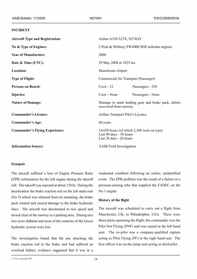
lug in the centre of the bogie beam at the other. The
arrangement of these components can be seen in the
diagram at Figure 1 and in the photographs of the
aircraft at Figure 2, taken shortly after the incident.
The brake rod attachment pin, or torque pin, is inserted
through the brake rod from the bogie beam side and
passes through the brake housing. It is retained by an
end cap, which is itself retained by a cross-bolt, nut
and split pin.
The brake reaction rod can be fitted at any wheel
17© Crown copyright 2009
AAIB Bulletin: 11/2009 N270AY EW/C2008/05/04
position. It will be appreciated, from a consideration of the geometry, that the rear axle brake rods are subjected to a tensile load during brake operation, while those at the front are placed in compression. The pin is loaded in single shear. The brake rods in each pair are linked together by a lanyard, which consists of a steel cable connected at either end to a clamp on each brake rod. This is a modification introduced by the landing gear manufacturer following an event in which an incorrectly
installed pin, of a previous design standard, became detached during takeoff. The lanyard is designed to restrict movement of the brake rods in the event of a pin failure.
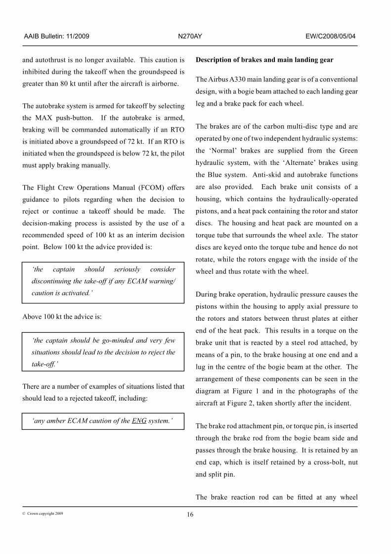
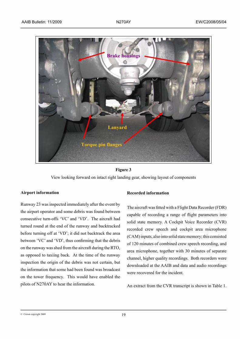
Figure 3 shows a photograph of the unaffected right landing gear of N270AY, showing the layout of the components described above.
Brake reaction rods
Figure 1
Main landing gear shown in ‘flying attitude’

18© Crown copyright 2009
AAIB Bulletin: 11/2009 N270AY EW/C2008/05/04
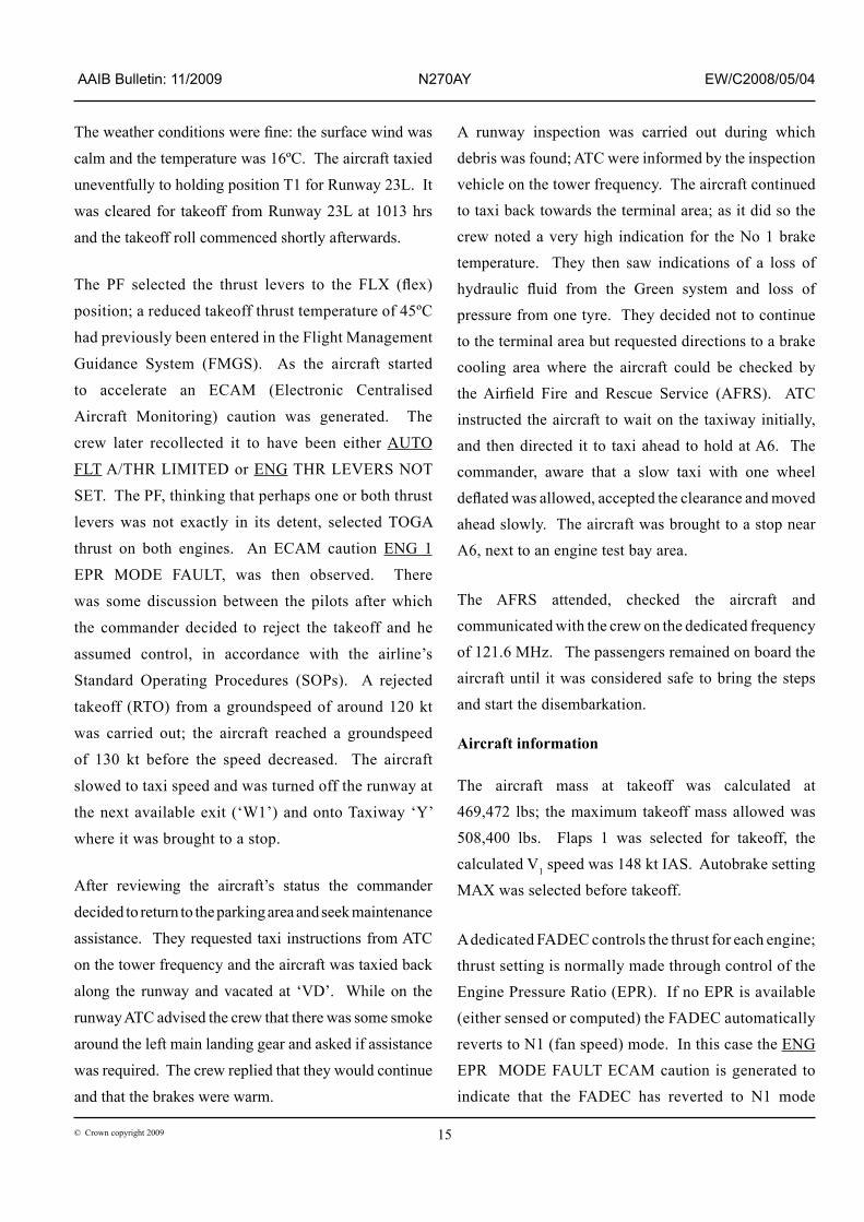
Deflated No 1 tyre
Disconnected brake reaction rod
Torque pin migrated into wheel rim following flange failure
Brake pistons
Figure 2
Views of the left landing gear. Note hydraulic fluid spillage
19© Crown copyright 2009
AAIB Bulletin: 11/2009 N270AY EW/C2008/05/04
Airport information
Runway 23 was inspected immediately after the event by the airport operator and some debris was found between consecutive turn-offs ‘VC’ and ‘VD’. The aircraft had turned round at the end of the runway and backtracked before turning off at ‘VD’; it did not backtrack the area between ‘Vc’ and ‘VD’, thus confirming that the debris on the runway was shed from the aircraft during the RTO, as opposed to taxiing back. At the time of the runway inspection the origin of the debris was not certain, but the information that some had been found was broadcast on the tower frequency. This would have enabled the pilots of N270AY to hear the information.
Recorded information
The aircraft was fitted with a Flight Data Recorder (FDR) capable of recording a range of flight parameters into solid state memory. A Cockpit Voice Recorder (CVR) recorded crew speech and cockpit area microphone (CAM) inputs, also into solid state memory; this consisted of 120 minutes of combined crew speech recording, and area microphone, together with 30 minutes of separate channel, higher quality recordings. Both recorders were downloaded at the AAIB and data and audio recordings were recovered for the incident.
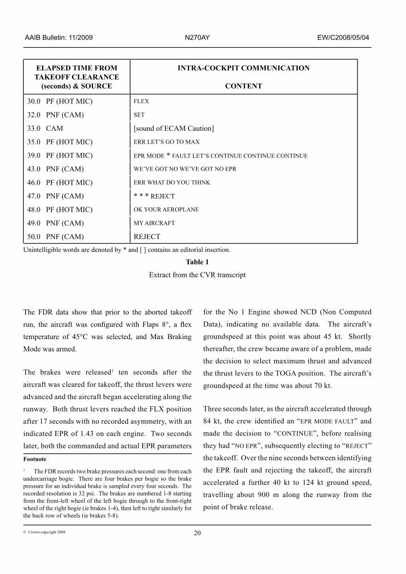
An extract from the CVR transcript is shown in Table 1.
Lanyard
Brake housings
Lanyard
Torque pin flanges
Figure 3
View looking forward on intact right landing gear, showing layout of components
20© Crown copyright 2009
AAIB Bulletin: 11/2009 N270AY EW/C2008/05/04
ELAPSED TIME FROM TAKEOFF CLEARANCE
(seconds) & SOURCE
INTRA-COCKPIT COMMUNICATION
CONTENT
30.0 PF (HOT MIC) FLEX
32.0 PNF (CAM) SET
33.0 CAM [sound of ECAM Caution]
35.0 PF (HOT MIC) ERR LET’S GO TO MAX
39.0 PF (HOT MIC) EPR MODE * FAULT LET’S CONTINUE CONTINUE CONTINUE
43.0 PNF (CAM) WE’VE GOT NO WE’VE GOT NO EPR
46.0 PF (HOT MIC) ERR WHAT DO yOU THINK
47.0 PNF (CAM) * * * REJECT
48.0 PF (HOT MIC) OK yOUR AEROPlANE
49.0 PNF (CAM) MY AIRCRAFT
50.0 PNF (CAM) REJECT
The FDR data show that prior to the aborted takeoff run, the aircraft was configured with Flaps 8°, a flex temperature of 45°C was selected, and Max Braking Mode was armed.
The brakes were released1 ten seconds after the aircraft was cleared for takeoff, the thrust levers were advanced and the aircraft began accelerating along the runway. Both thrust levers reached the FLX position after 17 seconds with no recorded asymmetry, with an indicated EPR of 1.43 on each engine. Two seconds later, both the commanded and actual EPR parameters
Footnote
1 The FDR records two brake pressures each second: one from each undercarriage bogie. There are four brakes per bogie so the brake pressure for an individual brake is sampled every four seconds. The recorded resolution is 32 psi. The brakes are numbered 1-8 starting from the front-left wheel of the left bogie through to the front-right wheel of the right bogie (ie brakes 1-4), then left to right similarly for the back row of wheels (ie brakes 5-8).
for the No 1 Engine showed NCD (Non Computed Data), indicating no available data. The aircraft’s groundspeed at this point was about 45 kt. Shortly thereafter, the crew became aware of a problem, made the decision to select maximum thrust and advanced the thrust levers to the TOGA position. The aircraft’s groundspeed at the time was about 70 kt.
Three seconds later, as the aircraft accelerated through 84 kt, the crew identified an “EPR MODE FAULT” and made the decision to “CONTINUE”, before realising they had “NO EPR”, subsequently electing to “REJECT” the takeoff. Over the nine seconds between identifying the EPR fault and rejecting the takeoff, the aircraft accelerated a further 40 kt to 124 kt ground speed, travelling about 900 m along the runway from the point of brake release.
Unintelligible words are denoted by * and [ ] contains an editorial insertion.
Table 1
Extract from the CVR transcript
21© Crown copyright 2009
AAIB Bulletin: 11/2009 N270AY EW/C2008/05/04
Maximum braking was then applied for about three seconds during which the Max Braking Mode disarmed as the crew applied brake pedal pressure. The maximum brake pressure is not clear given the low brake pressure sample rate but is evident from the longitudinal deceleration. However, no increase in the brake pressure (from a nominal zero) was recorded for the No 5 brake. Coincident with the application of maximum braking, both thrust levers were brought back to idle, and into reverse five seconds later. A recorded maximum groundspeed of 130 kt was reached during the aborted takeoff.
As the aircraft decelerated, the commanded EPR for the No 2 Engine showed NCD for 12 seconds, during which the actual EPR for the No 1 Engine became available again.
After turning around at the end of the runway, the aircraft spent the next 16 minutes taxiing back towards the terminal, before a low pressure warning activated for the Green hydraulic system. Zero brake pressure was recorded for the No 5 brake throughout the taxi.
Examination of the aircraft
Post Flight Report
The Aircraft Condition Monitoring System (ACMS) monitors the aircraft systems and records any faults. These include ECAM messages and can be logged in the form of pre-programmed reports that can be printed out on the flight deck. In addition, the system can be interrogated on the ground for the purpose of generating Maintenance Reports. In this case the Post Flight Report (PFR) listed the ‘ENG THR LEVERS NOT SET’ message, together with the EPR mode fault for the No 1 engine. The maintenance pages had additionally logged a message: ‘SENSE lINE P5 TO EEc’, which referred to a sensing tube that supplied a reference pressure, used
in calculating the EPR, to the Electronic Engine Control, or FADEC (see the next section of this report). There were also messages concerning the No 5 brake (normal system) servo valve and its associated brake temperature sensor. However, there were no messages that reflected the Green system hydraulic low-level warning. Engine examination
On removing the No 1 engine cowlings, it was apparent that the sensing tube that fed the ‘P4.95’ pressure to the FADEC, thus allowing the EPR to be calculated, had failed. The failure had resulted in the complete separation of the tube immediately adjacent to a clamp that attached the tube to the engine casing. The failure appeared to be the result of fatigue in the unsupported length of tube between two clamps. The loss of pressure resulting from the tube failure accounted for the EPR Mode Fault that occurred during the takeoff roll.
Landing gear
The aircraft was initially examined by the AAIB on the evening of the day of the incident. It had not been moved from the position on the taxiway where the flight crew had brought it to a halt.
Upon examination it was immediately apparent that the brake unit on the No 5 wheel (ie rear left wheel on the left landing gear bogie) had become disconnected from its associated brake reaction rod as a result of the failure of the attaching torque pin. As a result, the brake unit had been free to rotate with the wheel, causing the consequent failures of the hydraulic hoses and electrical harness that were attached to it; these failures were responsible for generating the PFR and Maintenance Reports. The tension in the hoses had in turn caused the failure of a bracket/cable guide assembly that was mounted on the bogie beam. It was clear that
22© Crown copyright 2009
AAIB Bulletin: 11/2009 N270AY EW/C2008/05/04
these components had acted as a flail, causing marks
on the side of the bogie beam and damage to a plastic,
cruciform-shaped bearing retaining device at the central
pivot on the bogie beam that attached front and rear left
hand brake rods. The security of the bearing had not
been compromised however. The detached part of the
retainer was among the debris found on the runway.
Other debris included pieces of the brake pin flange,
two lengths of braided hose, the broken-off piece of
bracket/cable guide and a bushing from the brake rod.
The No 1 tyre (ie the one ahead of the No 5 wheel)
had deflated following the RTO as a result of the heat
generated during the heavy braking, thereby causing
the activation of the fusible plug in the wheel. It was
subsequently noted that the No 6 tyre was showing
only 65 psi, as opposed to the normal pressure of
around 215 psi. It was found that the core within the
fusible plug had melted but had resolidified before
the tyre had become completely deflated. Otherwise,
none of the tyres displayed any evidence of damage,
such as skid-induced flats or cuts, that could have
been attributable to the incident.
The operator dispatched a maintenance team to
Manchester to repair the aircraft and prepare it for a
ferry-flight to its maintenance base in the USA.
The first task was to remove the No 5 wheel and brake
unit. As the wheel was removed from the axle, it
was apparent that the two outermost stator discs had
disintegrated. It was subsequently found impossible
to remove the brake pack from the axle sleeve as
a result of heat-induced distortion, with the heat
being generated by brake-unit rotation on the sleeve
following the torque pin failure. However, the sleeve
had not rotated relative to the axle. The axle sleeve
and brake unit were therefore removed as a complete
item and subsequently taken for examination at the brake manufacturer’s UK facility.
The brake rod attachment pin had migrated in an outboard direction within the brake housing to the extent that the end of the pin had been in contact with the wheel rim as it rotated; some swarf had been generated as a result. The pin had been able to move axially in the bore in the brake housing due to the fracture of the flange at the head end. The pin was removed by driving it out of the housing, following which it was subjected to specialist metallurgical examination.
It was found that the lanyard linking the two rear brake reaction rods (ie on wheel Nos 5 and 6) had broken, which had allowed the No 5 brake rod aft end to trail on the ground. A flat area had been ground away on the rod end as a result of contact with the runway/taxiway. It was unclear how the brake rod had been able to move the necessary distance to generate a significant tension in the lanyard, since upward and outboard movement is constrained by the close proximities of the axle housing and brake housing respectively. The only other visible damage to the brake rod was the inboard half-bushing at the aft end was missing; this was among the items recovered from the runway. The bushing and brake rod were subsequently returned to the landing gear manufacturer for additional investigation.
Examination of the brake unit
The examination of the brake unit at the manufacturer’s UK facility was conducted in the presence of representatives from Airbus UK and the AAIB. The fragments from the broken stator discs were examined, with a lack of oxidation on the fracture faces indicating that they were recent and thus had probably broken during the RTO, as opposed to having been in that state for a number of landings.
23© Crown copyright 2009
AAIB Bulletin: 11/2009 N270AY EW/C2008/05/04
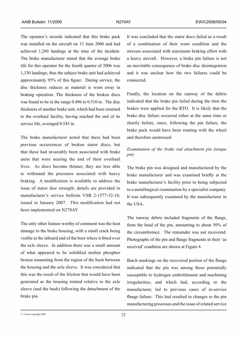
The operator’s records indicated that this brake pack was installed on the aircraft on 15 June 2006 and had achieved 1,260 landings at the time of the incident. The brake manufacturer stated that the average brake life for this operator for the fourth quarter of 2006 was 1,330 landings; thus the subject brake unit had achieved approximately 95% of this figure. During service, the disc thickness reduces as material is worn away in braking operation. The thickness of the broken discs was found to be in the range 0.496 to 0.510 in. The disc thickness of another brake unit, which had been returned to the overhaul facility, having reached the end of its service life, averaged 0.545 in.
The brake manufacturer noted that there had been previous occurrences of broken stator discs, but that these had invariably been associated with brake units that were nearing the end of their overhaul lives. As discs become thinner, they are less able to withstand the pressures associated with heavy braking. A modification is available to address the issue of stator disc strength; details are provided in manufacturer’s service bulletin VSB 2-1577-32-10, issued in January 2007. This modification had not been implemented on N270AY.
The only other feature worthy of comment was the heat damage to the brake housing, with a small crack being visible at the inboard end of the bore where it fitted over the axle sleeve. In addition there was a small amount of what appeared to be solidified molten phosphor bronze emanating from the region of the bush between the housing and the axle sleeve. It was considered that this was the result of the friction that would have been generated as the housing rotated relative to the axle sleeve (and the bush) following the detachment of the brake pin.
It was concluded that the stator discs failed as a result of a combination of their worn condition and the stresses associated with maximum braking effort with a heavy aircraft. However, a brake pin failure is not an inevitable consequence of brake disc disintegration and it was unclear how the two failures could be connected.
Finally, the location on the runway of the debris indicated that the brake pin failed during the time the brakes were applied for the RTO. It is likely that the brake disc failure occurred either at the same time or shortly before, since, following the pin failure, the brake pack would have been rotating with the wheel and therefore unstressed.
Examination of the brake rod attachment pin (torque pin)
The brake pin was designed and manufactured by the brake manufacturer and was examined briefly at the brake manufacturer’s facility prior to being subjected to a metallurgical examination by a specialist company. It was subsequently examined by the manufacturer in the USA.
The runway debris included fragments of the flange, from the head of the pin, amounting to about 50% of the circumference. The remainder was not recovered. Photographs of the pin and flange fragments in their ‘as received’ condition are shown at Figure 4.
Batch markings on the recovered portion of the flange indicated that the pin was among those potentially susceptible to hydrogen embrittlement and machining irregularities, and which had, according to the manufacturer, led to previous cases of in-service flange failure. This had resulted in changes to the pin manufacturing processes and the issue of related service

24© Crown copyright 2009
AAIB Bulletin: 11/2009 N270AY EW/C2008/05/04
Fracturedflanged end
Longitudinalcracks
Figure 4
No 5 torque pin together with flange fragments that were found on the runway
25© Crown copyright 2009
AAIB Bulletin: 11/2009 N270AY EW/C2008/05/04
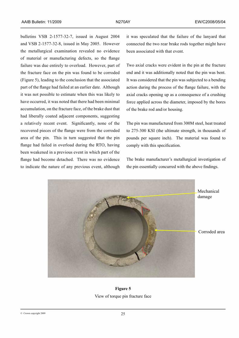
bulletins VSB 2-1577-32-7, issued in August 2004 and VSB 2-1577-32-8, issued in May 2005. However the metallurgical examination revealed no evidence of material or manufacturing defects, so the flange failure was due entirely to overload. However, part of the fracture face on the pin was found to be corroded (Figure 5), leading to the conclusion that the associated part of the flange had failed at an earlier date. Although it was not possible to estimate when this was likely to have occurred, it was noted that there had been minimal accumulation, on the fracture face, of the brake dust that had liberally coated adjacent components, suggesting a relatively recent event. Significantly, none of the recovered pieces of the flange were from the corroded area of the pin. This in turn suggested that the pin flange had failed in overload during the RTO, having been weakened in a previous event in which part of the flange had become detached. There was no evidence to indicate the nature of any previous event, although
it was speculated that the failure of the lanyard that
connected the two rear brake rods together might have
been associated with that event.
Two axial cracks were evident in the pin at the fracture
end and it was additionally noted that the pin was bent.
It was considered that the pin was subjected to a bending
action during the process of the flange failure, with the
axial cracks opening up as a consequence of a crushing
force applied across the diameter, imposed by the bores
of the brake rod and/or housing.
The pin was manufactured from 300M steel, heat treated
to 275-300 KSI (the ultimate strength, in thousands of
pounds per square inch). The material was found to
comply with this specification.
The brake manufacturer’s metallurgical investigation of
the pin essentially concurred with the above findings.
Corroded area
Mechanical damage
Figure 5
View of torque pin fracture face

26© Crown copyright 2009
AAIB Bulletin: 11/2009 N270AY EW/C2008/05/04
The possibility of a previous event having been responsible for a partial failure of the flange prompted questions to the operator regarding any recent heavy or ‘crabbed’ landings, pivot turns during ground manoeuvring, or operation with tyres in a deflated condition. The operator stated that there were no records of any such occurrences, although the No 5 tyre was changed, due to being worn to limits, on 24 May, five days before this incident.
Examination of the brake reaction rod
As noted earlier, there was little visible damage to the brake rod; this included the removal of a half-bushing and the damage arising from the runway contact. The rod surface was protected by a thick layer of anti-chip paint, and some scuffing was observed on the rear outboard region. The paint was removed during the examination at the manufacturers, which revealed that the surface underneath was undamaged. A dimensional check revealed that apart from some damage in the bore at the rear of the rod, which was associated with the bush removal, there had been no significant plastic deformation of the component.
The cable that formed the principal component of the lanyard that had joined the two rear brake rods together was found to have failed in overload. The landing gear manufacturer stated that the tensile failure load of the cable was approximately 4,000 lb force, but could not explain how the rod could have moved a sufficient distance to have generated any significant tension, especially in the absence of significant deformation of the rod. Also, the cable was outside the plane of rotation of the flailing items, such as the brake hoses and metal guide, and so they could not have been responsible for the failure. It was confirmed that the brake rod would not contact the ground after the pin failure, so long as the lanyard remained intact.
The landing gear manufacturer calculated that an aft load applied to the lanyard would, at the point of cable failure, apply an axial load of approximately 2,750 lb force to the brake pin. The force required to fail the pin flange would, however, be an order of magnitude more.
Prior to removing the paint from the surface of the rod, it was observed that the clamp that anchored the lanyard had a small build-up of partially removed paint against its aft face. This feature was consistent with a load on the lanyard in an aft direction such that it resulted in a tendency for the lower edge of the clamp to peel back the layer of paint that abutted it. Such a load might have arisen from, for example, the bogie running over an obstruction, which fouled the lanyard: however, the aircraft did not leave the paved surface during the incident, thus limiting the scope for encountering such an obstruction. Furthermore any obstruction might reasonably be expected to break the front brake rod lanyard also, since it is at the same height above the ground. Finally, a microscopic examination of the individual strands of the failed cable did not reveal the presence of any foreign material that might have originated from an object brought into violent contact with the lanyard. However, it was observed that the bundle of fractured wires on each half of the lanyard was bent, as though they had been caught around an object prior to failure.
It was considered that an event that resulted in the snagging of only the rear lanyard could conceivably have occurred with the gear bogie in its ‘flying’ attitude. This would necessarily have happened in the landing or takeoff phase, and would probably in itself have constituted a reportable occurrence. No evidence of such an incident came to light during the investigation, but it was nevertheless considered potentially useful to examine the No 6 brake rod attachment pin (ie opposite

27© Crown copyright 2009
AAIB Bulletin: 11/2009 N270AY EW/C2008/05/04
the No 5 pin) for evidence of distress. Unfortunately, following a request to retrieve this component, it went missing in transit.
Landing gear tests
The final part of the landing gear investigation consisted of a test at Airbus UK’s landing gear test facility using representative components. This involved removing the brake rod torque pin and disconnecting the hydraulic hoses and electrical harnesses before rotating the brake unit in order to examine the possibility of various components coming into conflict. This revealed that a stainless hose guide mounted on the front of the brake housing had been installed back to front on the incident aircraft. The only immediate consequence of this was
that the guide jutted in a forward, as opposed to aft direction, which, with the bogie in its flying attitude, caused its associated hydraulic hose to be somewhat taut. However, following the removal of the brake pin and consequent rotation of the brake unit, it was found the guide contacted the brake reaction rod in the manner shown in Figure 6, where it can be seen that the profiles of the guide edge and the aft flank of the rod closely match. (Note: the landing gear was fixed in the flying attitude for the duration of the test, although contact between the guide and brake rod would still have occurred on the ground.) The guide had been rotated into the as-shown position by the tension generated in the hydraulic hose, which had sheared one of the two attaching bolts. The contact accounted for the marks on the anti-chip pain. It
Brake reaction rod Cable guide from incident aircraft
Lanyard clamp
Figure 6
View of test showing how cable guide on brake housing may have contacted the brake reaction rod

28© Crown copyright 2009
AAIB Bulletin: 11/2009 N270AY EW/C2008/05/04
was also noted that the downward component of the force on the rod, generated during the process of distorting the guide, imparted a tension in the lanyard, thus providing a potential mechanism for failing the lanyard cable.
Green hydraulic system
After the RTO the crew reported a Low Level indication for the Green hydraulic system, which was repeated on the Hydraulic System ECAM page when electrical power was restored on the aircraft during the investigation. Despite this, the PFR had logged no record of this warning. confirmation from the DFDR was not possible, as there was no hydraulic system Low Level warning discrete. During the examination of the aircraft, considerable fluid spillage was observed, which led to an assumption that the Green reservoir had emptied following the rupture of the No 5 brake hoses. The reservoir had a capacity of up to 52 litres, with the Low Level warning set at 8 litres. For such a potentially large volume of fluid to have escaped suggested that the hydraulic fuse in the brake line downstream of the servo-valve, which should have limited the flow, had failed. However, during the time the aircraft was being prepared for the ferry flight to the USA, the fuse was not replaced and although there was anecdotal evidence that less than three litres were required to top up the system, this was not confirmed by any written record. The issue was thus not resolved, meaning that either there was a substantial fluid loss, together with an unexplained lack of a PFR report, or the loss of fluid was limited by the hydraulic fuse, accompanied by an erroneous low level flight deck indication. Given the extent of fluid deposited on the ground around the aircraft after it had halted, which would have been in addition to that which is likely to have been lost in the braking and taxiing operations, the first of the two scenarios seems the more probable. In addition, Airbus indicated that the system pressure must be in excess of approximately 0.5 bar in order to keep the fuse closed.
Previous events
EPR sensing tube
Airbus was aware of one other incident involving the P4.95 sensing tube, which occurred on another A330 in October 2007 and which also resulted in a rejected takeoff. In that case the tube did not fail completely, but developed a leak which, although causing a low EPR indication, was insufficient to trigger a reversion to N1 control mode; this resulted in an N1 overspeed warning.
The engine manufacturer noted that they had received 38 reports of tube fractures on the various P4.95 sensing manifold assemblies on PW4000-100 engines: these had resulted in air turnbacks and a diversion and had additionally prevented aircraft dispatches under ETOPS operation. The failures were identified as having occurred as a result of low-cycle fatigue, due to differential thermal expansion between the manifold assemblies and the turbine exhaust casing.
Torque pin failure
The aircraft manufacturer stated that there had been very few previous failures of a torque pin flange, although there were four cases of cracks being found in the flange radius due to the hydrogen embrittlement and machining irregularities that were discussed earlier.
Analysis
The crew noticed a fault with the thrust setting at a fairly early stage of the takeoff roll. The attempted corrective action of setting TOGA thrust was unsuccessful, and a further ECAM caution, EPR MODE FAULT, was observed. As this caution is inhibited above 80 kt, it must have occurred below this speed. There was a delay of a few seconds before the decision to reject
29© Crown copyright 2009
AAIB Bulletin: 11/2009 N270AY EW/C2008/05/04
the takeoff was made, during which time the aircraft reached a maximum groundspeed of 130 kt. This delay made the RTO a relatively high-energy event. The delay occurred because the initial decision by the PF to continue the takeoff after receiving the EPR MODE FAULT caution was reconsidered by both pilots and reversed. Time to analyse what was happening was short and, in accordance with the SOPs, the commander had to take control and carry out the rejected takeoff. Had the takeoff been continued, the FADEC would have continued to operate in N1 mode, although autothrust would not have been available for the remainder of the flight.
The crew remained unaware of the damage sustained by the aircraft until they had taxied some distance and the loss of hydraulic fluid and high brake temperature became apparent. The message from the runway inspection about debris having been found could have alerted them, but either they did not hear it or thought that the debris was not from their aircraft. When they realised the brake temperatures were very high they asked to go to a brake cooling area where the aircraft could wait until it was safe to be approached. However, once one tyre had deflated, their ability to move the aircraft was limited.
Three factors featured in the landing gear investigation: the disintegration of the two brake stator discs, the torque pin flange failure and the failure of the lanyard that connected the rear brake reaction rods.
Whilst the discs, which had achieved approximately 95% of the average brake life, most probably failed as a result of the torque spike associated with the use of MAX autobrake, the pin failed simultaneously due to being in a weakened state following an earlier and therefore unrelated incident. No evidence came to
light that indicated the nature or even the existence of such an incident, although it was speculated that it might have been associated with the failure of the lanyard cable. If the cable did fail during the RTO, a potential cause was identified in the form of contact between a wrongly-installed hose guide, which had become displaced when the brake unit started to rotate, and the brake reaction rod. However, the glancing nature of this contact was unconvincing; moreover, it did not account for the observed rearward movement of the lanyard clamp, or the bent ends of the fractured strands of the cable, which together tended to favour the possibility of snagging an obstruction. On the other hand, such an event would also have left the failed cable ends potentially visible during pre-flight inspections.
Calculations indicated that the pin would sustain an axial load on the flange an order of magnitude higher than the failure load of the cable. However, a sharp pull, in an aft direction, on the cable would tend to draw the rear ends of the pair of brake rods together, which in turn could preferentially load the rear arcs of the flanges, as opposed to imparting a uniform load around the flange circumference.
Safety action
Following the investigation, Airbus UK indicated that they would revise the Aircraft Maintenance Manual (AMM), to provide sufficient information to ensure the correct installation of the cable guide.
Although it is likely that the torque pin failed under the action of peak brake torque during the RTO, it did so having lost part of its flange in an earlier event. Since the nature of this event was not apparent, it was not possible for either the airframe or the landing gear manufacturer to propose any appropriate safety action.
30© Crown copyright 2009
AAIB Bulletin: 11/2009 N270AY EW/C2008/05/04
As noted earlier, the engine manufacturer had identified the P4.95 sensing tube failures as being the result of low-cycle fatigue, arising from differential thermal expansion between the manifold assemblies and the turbine exhaust casing. It was also determined that the assemblies and their associated mounting brackets were too rigid. These problems were addressed by Service Bulletin PW4G-100-77-12, which was issued on 2 May 2007. This introduced sensing manifold
assemblies having a different tube material and wall thickness, together with redesigned contours to reduce stress concentrations.
The operator of N270AY stated that SB PW4G-100-77-12 was in the process of being embodied across the fleet at each engine shop visit. The failed tube was of a pre-modification standard.