inca-flexray v7.2 user manual en - etas inca-flexray v7.2 - user manual introduction etas...
TRANSCRIPT

INCA-FLEXRAY V7.2User Manual

2
Copyright
The data in this document may not be altered or amended without special noti-fication from ETAS GmbH. ETAS GmbH undertakes no further obligation in rela-tion to this document. The software described in it can only be used if thecustomer is in possession of a general license agreement or single license. Usingand copying is only allowed in concurrence with the specifications stipulated inthe contract.
Under no circumstances may any part of this document be copied, reproduced,transmitted, stored in a retrieval system or translated into another languagewithout the express written permission of ETAS GmbH.
© Copyright 2010-2016 ETAS GmbH, Stuttgart
The names and designations used in this document are trademarks or brandsbelonging to the respective owners.
Document AM010103 V7.2 R01 EN - 03.2016
Contents
ETAS Contents
1 Introduction . . . . . . . . . . . . . . . . . . . . . . . . . . . . . . . . . . . . . . . . . . . . . . . . . . . . . . 51.1 Safety Notice . . . . . . . . . . . . . . . . . . . . . . . . . . . . . . . . . . . . . . . . . . . . . . . . 51.2 General Description . . . . . . . . . . . . . . . . . . . . . . . . . . . . . . . . . . . . . . . . . . . 51.3 Definitions . . . . . . . . . . . . . . . . . . . . . . . . . . . . . . . . . . . . . . . . . . . . . . . . . . 61.4 Restrictions concerning INCA-FLEXRAY Support by Other Products . . . . . . . . 71.5 About this Manual . . . . . . . . . . . . . . . . . . . . . . . . . . . . . . . . . . . . . . . . . . . . 8
2 New Features in INCA-FLEXRAY V7. . . . . . . . . . . . . . . . . . . . . . . . . . . . . . . . . . . . . 92.1 New Features in INCA-FLEXRAY V7.1 . . . . . . . . . . . . . . . . . . . . . . . . . . . . . . 9
2.1.1 Support of FlexRay V3.0 and V3.1 . . . . . . . . . . . . . . . . . . . . . . . . . . 92.1.2 Selection of Startup/Sync Controller in the Hardware Configuration
Editor . . . . . . . . . . . . . . . . . . . . . . . . . . . . . . . . . . . . . . . . . . . . . . . 92.2 New Features in INCA-FLEXRAY V7.2 . . . . . . . . . . . . . . . . . . . . . . . . . . . . . 10
3 Installing INCA-FLEXRAY . . . . . . . . . . . . . . . . . . . . . . . . . . . . . . . . . . . . . . . . . . . . 113.1 Package Contents . . . . . . . . . . . . . . . . . . . . . . . . . . . . . . . . . . . . . . . . . . . . 113.2 System Requirements . . . . . . . . . . . . . . . . . . . . . . . . . . . . . . . . . . . . . . . . . 113.3 Installing INCA-FLEXRAY from CD-ROM . . . . . . . . . . . . . . . . . . . . . . . . . . . 11
4 Using the INCA-FLEXRAY Add-on in INCA. . . . . . . . . . . . . . . . . . . . . . . . . . . . . . . 134.1 Setting up the Workspace . . . . . . . . . . . . . . . . . . . . . . . . . . . . . . . . . . . . . . 134.2 Configuring the FlexRay Hardware . . . . . . . . . . . . . . . . . . . . . . . . . . . . . . . 14
4.2.1 Configuring the FlexRay Hardware for FlexRay Monitoring. . . . . . . 154.2.2 Configuring the FlexRay Hardware for Measurement and Calibration
via XCP on FlexRay . . . . . . . . . . . . . . . . . . . . . . . . . . . . . . . . . . . . 184.3 Configuring the Experiment and starting FlexRay Monitoring . . . . . . . . . . . 20
5 Appendix . . . . . . . . . . . . . . . . . . . . . . . . . . . . . . . . . . . . . . . . . . . . . . . . . . . . . . . 235.1 Restrictions . . . . . . . . . . . . . . . . . . . . . . . . . . . . . . . . . . . . . . . . . . . . . . . . . 23
5.1.1 Some FIBEX Data Types are not supported. . . . . . . . . . . . . . . . . . . 23
INCA-FLEXRAY V7.2 - User Manual 3

4
Contents ETAS
5.1.2 Data with FlexRay PreambleIndicatorBit Set is Discarded . . . . . . . . 235.1.3 FlexRay Network temporarily shuts down on Hardware Initialization235.1.4 FlexRay Bus Load leads to PC Overload . . . . . . . . . . . . . . . . . . . . . 235.1.5 ASAM MCD-3 (new) / ASAP3 . . . . . . . . . . . . . . . . . . . . . . . . . . . . 245.1.6 Flashing and Diagnosis over the XCP Interface are not Supported . 24
5.2 Tips and Tricks . . . . . . . . . . . . . . . . . . . . . . . . . . . . . . . . . . . . . . . . . . . . . . 255.2.1 Selecting Variables by Frame, ECU or Signal Group . . . . . . . . . . . . 25
6 ETAS Contact Addresses . . . . . . . . . . . . . . . . . . . . . . . . . . . . . . . . . . . . . . . . . . . . 27
INCA-FLEXRAY V7.2 - User Manual
ETAS Introduction
1 Introduction
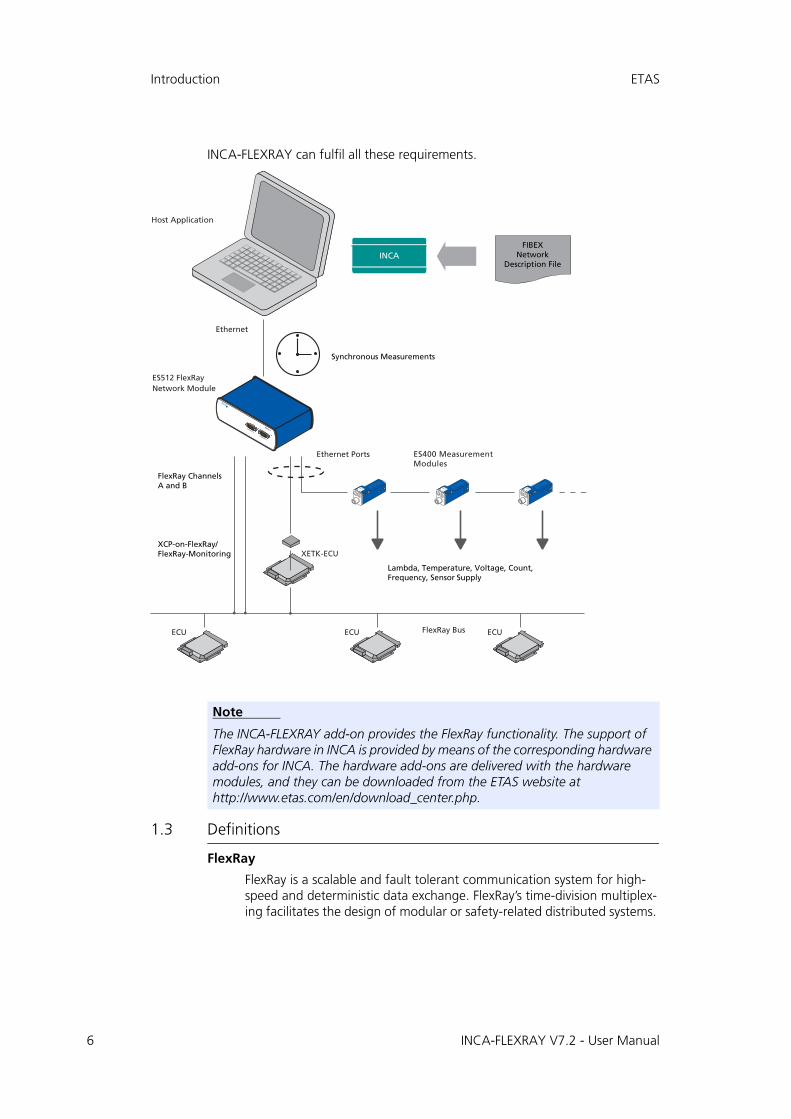
The FlexRay bus system is a standardized communication system which is becom-ing increasingly important for automotive engineering projects, because limita-tions of the amount of data on the CAN bus can be overcome, and redundanciesmake it possible to use FlexRay in safety-critical use cases. Moreover the deter-ministic design ensures a reliable transmission of messages.
INCA supports measurement and calibration of ECUs in vehicles that areequipped with a FlexRay bus by monitoring signals on the FlexRay channels intheir physical representation, as well as measurement and calibration via the XCPon FlexRay interface. The time stamps of the data samples are synchronized withall other data sources within INCA to enable causal analysis as well as error track-ing within the investigated system.
While performing the ECU calibration via ETK, CAN, or XCP on FlexRay, the usercan sample the signals on the FlexRay channels and store them together with allother data acquired by INCA in the measurement file for offline analysis. For theuser‘s convenience, the integration of FlexRay monitoring keeps close to the wellknown and established CAN-Monitoring functionality in INCA.
The signals to be calibrated or monitored can be selected from all signals avail-able in the connected cluster; the FlexRay monitoring signals are defined in theFIBEX file, the measurement and calibration variables are defined in the projectdescribing files (*.a2l).
INCA imports the FIBEX file to get information on the FlexRay cluster. In addition,INCA uses the information from FIBEX to configure the interface hardware.
1.1 Safety Notice
1.2 General Description
In typical FlexRay use cases, users often would like to carry out several tasks atthe same time:
• Measuring and calibrating ECUs with ETK / CAN / XCP on FlexRay
• Monitoring the in-vehicle FlexRay Bus with synchronized time stamps
• Measuring signals and analyzing them later
In these tasks, the user would like to
• work with physical signals (temperature, voltage, ...)
• use files for the network description which are compliant to the FIBEX standard
WARNING!
Calibration activities influence the behavior of the ECU and the sys-tems controlled by the ECU. This may result in unexpected behavior of the vehicle and thus can lead to safety critical situations.Only well trained personnel should be allowed to perform calibration activities.
INCA-FLEXRAY V7.2 - User Manual 5
6
Introduction ETAS
INCA-FLEXRAY can fulfil all these requirements.
1.3 Definitions
FlexRay
FlexRay is a scalable and fault tolerant communication system for high-speed and deterministic data exchange. FlexRay’s time-division multiplex-ing facilitates the design of modular or safety-related distributed systems.
Note
The INCA-FLEXRAY add-on provides the FlexRay functionality. The support of FlexRay hardware in INCA is provided by means of the corresponding hardware add-ons for INCA. The hardware add-ons are delivered with the hardware modules, and they can be downloaded from the ETAS website at http://www.etas.com/en/download_center.php.
INCA-FLEXRAY V7.2 - User Manual

ETAS Introduction
Its high bandwidth of 10 MBaud on two channels helps to cope with the high network load caused by the increasing amount of innovative elec-tronic systems in modern vehicles.
The communication system’s specifications are released by the FlexRay consortium which is widely supported by vehicle manufacturers and sup-pliers worldwide.
FIBEX
FIBEX (Field Bus Exchange) is an exchange format based on XML schema which is used for complete descriptions of the in-vehicle communication network. FIBEX is defined for various network types (CAN, LIN, MOST, FlexRay) and contains information about the bus architecture, signals, controller properties etc.
INCA uses FIBEX files to align tools and ECUs with the communication scheme given by the FlexRay cluster, i.e. the FIBEX file defines the signals which can be monitored via INCA in the connected cluster, and it contains data for the configuration of the interface hardware. The FIBEX file describes the whole FlexRay cluster; there is only one FIBEX file per cluster. If you are using the XCP on FlexRay interface, the definitions in the FIBEX file (description of the FlexRay cluster with the reserved frames for the XCP protocol) and the definitions in the A2L files of the ECUs that are part of the cluster (description of the available buffers for the XCP protocol of one ECU) must be consistent.
The FIBEX files have to be provided by the vehicle manufacturer.
The FIBEX file format is standardized by ASAM (Association for Standardisation of Automation- and Measuring Systems). INCA currently supports the following FIBEX baseline versions:
– FIBEX V1.1.5a
– FIBEX V1.2.0a
– FIBEX V2.0.0
– FIBEX V2.0.1
– FIBEX V3.0
– FIBEX V3.1
– Audi/VW specific FIBEX format
For further information please refer to the description of the FIBEX standard at http://www.asam.net.
XCP
eXtended Calibration Protocol; XCP is a vendor- and interface-indepen-dent protocol for communication between calibration tools and control units. XCP was specified in the ASAM e.V.
1.4 Restrictions concerning INCA-FLEXRAY Support by Other Products
• INCA-FLEXRAY support of IXXAT CCM hardware
INCA-FLEXRAY does not support the IXXAT CCM FlexRay hardware.
INCA-FLEXRAY V7.2 - User Manual 7

8
Introduction ETAS
• INCA-FLEXRAY not supported by ES71x Drive Recorder
The ES71x does not support the add-on INCA-FLEXRAY.
If you need FlexRay functionality for your ES71x please contact your ETAS office or the ES71x product management.
1.5 About this Manual
This manual addresses qualified personnel working in the fields of automobileECU development and calibration. Specialized knowledge in the areas of mea-surement and control unit technology is required. Moreover users need to beable to work with INCA and know the basic functionality.
The INCA-FLEXRAY manual consists of the following chapters:
• "Introduction" on page 5
This chapter contains some general information on the INCA-FLEXRAY add-on and the underlying concepts.
• "New Features in INCA-FLEXRAY V7" on page 9
This chapter contains a summary of the new features and changes.
You should read this section even if you are an experienced INCA-FLEX-RAY user.
• "Installing INCA-FLEXRAY" on page 11
The installation chapter contains information on the scope of delivery, hardware and software requirements and describes the procedures used to install INCA-FLEXRAY.
• "Using the INCA-FLEXRAY Add-on in INCA" on page 13
This chapter addresses users who are new to INCA-FLEXRAY. Practice-ori-ented examples in tutorial style show you how to use INCA-FLEXRAY.
• "Appendix" on page 23
This chapter provides information on restrictions within INCA-FLEXRAY as well as tips and tricks for the user.
INCA-FLEXRAY V7.2 - User Manual
ETAS New Features in INCA-FLEXRAY V7
2 New Features in INCA-FLEXRAY V7
This section contains a summary of the new features that have been introducedin INCA-FLEXRAY V7. You should read this section even if you are already anexperienced INCA-FLEXRAY user.
2.1 New Features in INCA-FLEXRAY V7.1
2.1.1 Support of FlexRay V3.0 and V3.1
INCA-FLEXRAY V7.1 additionally supports the FIBEX versions V3.0 and V3.1.
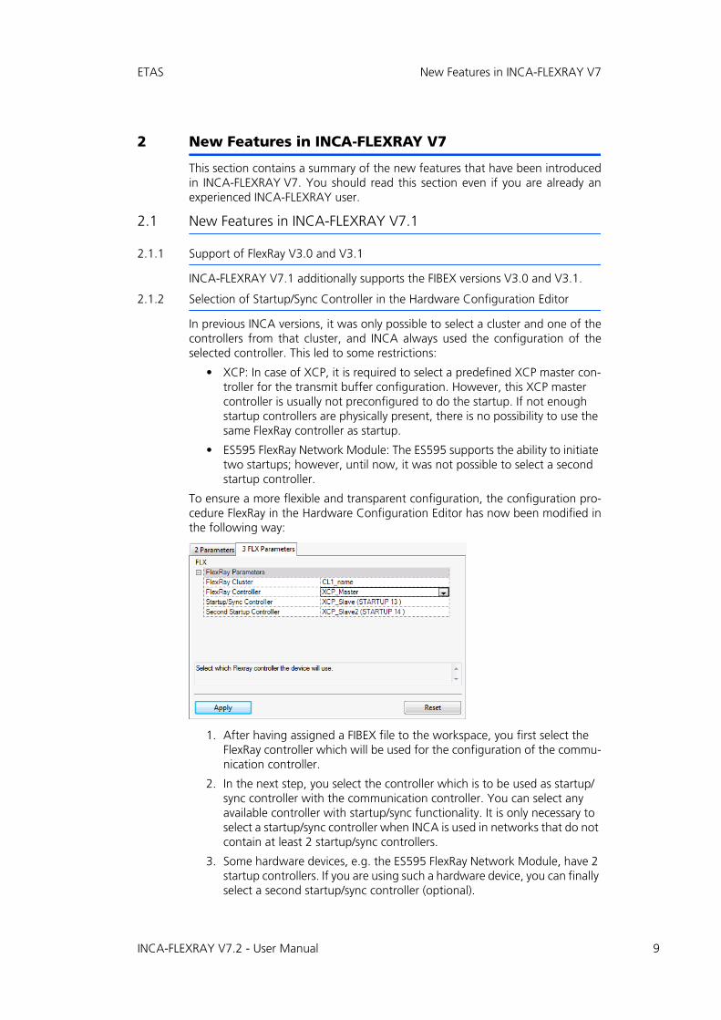
2.1.2 Selection of Startup/Sync Controller in the Hardware Configuration Editor
In previous INCA versions, it was only possible to select a cluster and one of thecontrollers from that cluster, and INCA always used the configuration of theselected controller. This led to some restrictions:
• XCP: In case of XCP, it is required to select a predefined XCP master con-troller for the transmit buffer configuration. However, this XCP master controller is usually not preconfigured to do the startup. If not enough startup controllers are physically present, there is no possibility to use the same FlexRay controller as startup.
• ES595 FlexRay Network Module: The ES595 supports the ability to initiate two startups; however, until now, it was not possible to select a second startup controller.
To ensure a more flexible and transparent configuration, the configuration pro-cedure FlexRay in the Hardware Configuration Editor has now been modified inthe following way:
1. After having assigned a FIBEX file to the workspace, you first select the FlexRay controller which will be used for the configuration of the commu-nication controller.
2. In the next step, you select the controller which is to be used as startup/sync controller with the communication controller. You can select any available controller with startup/sync functionality. It is only necessary to select a startup/sync controller when INCA is used in networks that do not contain at least 2 startup/sync controllers.
3. Some hardware devices, e.g. the ES595 FlexRay Network Module, have 2 startup controllers. If you are using such a hardware device, you can finally select a second startup/sync controller (optional).
INCA-FLEXRAY V7.2 - User Manual 9

10
New Features in INCA-FLEXRAY V7 ETAS
2.2 New Features in INCA-FLEXRAY V7.2
INCA-Flexray now supports electronic licenses. These licenses will be provided asthree different types:
1. Machine based license: The license is bound to the mac address of the network card from the computer.
2. User based license: The license is bound to the user account in a domain.
3. Floating license: There is a certain number of licenses on a server. On use, INCA-Flexray will borrow a license from the server. After closing INCA, the license will be available again for other users.
INCA-FLEXRAY V7.2 - User Manual
ETAS Installing INCA-FLEXRAY
3 Installing INCA-FLEXRAY
This chapter is for all users who install the INCA-FLEXRAY add-on on a PC. It alsocontains information on hardware and software requirements and the prepara-tion required for installation.
3.1 Package Contents
The INCA-FLEXRAY add-on consists of the following items which have to beordered separately:
• INCA-FLEXRAY software license
• CD ROM including
– Program files for the INCA-FLEXRAY add-on
– Manual in PDF format (Acrobat Reader)
– Product information in PDF format (Acrobat Reader)
– Demo Clip in avi format (Windows Media Player)
3.2 System Requirements
INCA-FLEXRAY V7.2 requires the following hardware and software:
• INCA V7.1;Please refer to the INCA Getting Started manual for the INCA system requirements.
• INCA-FLEXRAY hardware interface1
3.3 Installing INCA-FLEXRAY from CD-ROM
Please note that you must have administrator privileges to install theINCA-FLEXRAY add-on.
To install the INCA-FLEXRAY Add-on:
• Make sure that INCA is installed on your computer and that the release number of the INCA installa-tion is compatible with the release number of the INCA-FLEXRAY add-on.
• Close all active programs.
• Insert the CD with the installation program into the CD-ROM drive of your computer.
• If the installation CD does not start automatically, either execute the autostart.exe program on the CD to start the user interface of the CD or search for the Inca_AddOn-FLEXRAY.exe pro-gram on the CD and double-click it to start the installation routine manually.
1. If you are using the ES520 FlexRay and CAN Interface Module, you also need to install the ES520 Driver (UCI, Universal Communication Interface) and the corresponding firmware version. The ES520 Driver (UCI) is a PC driver which is required as the interface between the ES520 and INCA.The ES520 Driver (UCI) is provided together with HSP (Hardware Service Pack-age).
INCA-FLEXRAY V7.2 - User Manual 11

12
Installing INCA-FLEXRAY ETAS
• Follow the instructions in the installation routine to install the INCA-FLEXRAY add-on on your com-puter.
INCA-FLEXRAY V7.2 - User Manual
ETAS Using the INCA-FLEXRAY Add-on in INCA
4 Using the INCA-FLEXRAY Add-on in INCA
This chapter gives an example of how INCA-FLEXRAY can be used in INCA. Itdescribes a typical course of action for FlexRay monitoring as well as measure-ment and calibration via the XCP on FlexRay interface.
Before you can start monitoring the FlexRay bus via INCA, you have to prepareINCA for that task. Working with INCA-FLEXRAY comprises the following basictasks:
• Setting up the workspace in the Database Manager
• Configuring the FlexRay hardware in the Hardware Configuration Editor
• Configuring the experiment and starting monitoring and calibrating in the Experiment Environment
The course of action resembles the usual procedure for preparing and carryingout measurement and calibration tasks. For the description of the FlexRay cluster,however, FIBEX files are used. These are handled in the same way as CANdb files.
The following sections describe the basic procedures applied when working withFlexRay from within INCA. In some cases there is more than one way of perform-ing a task, e.g. FIBEX files can be added either in the Database Manager or in theHardware Configuration Editor. The following description provides an exampleof one typical course of action.
4.1 Setting up the Workspace
In the first step of preparing FlexRay monitoring, you create a new database andworkspace and add a FIBEX file to the database.
The FIBEX file has to be provided by the vehicle manufacturer. It contains adescription of the configuration of the measurement hardware as well as of thesignals which are available through the FlexRay bus.
To set up the Workspace:
• Create a new database:
– Select Database New.
– In the New Database dialog, enter Flex-Ray_Demo.
– Click OK.
• Create a top folder in the database:
– Select Edit Add Add top folder.
– Rename the new folder Demo and press <ENTER>.
• Create a new workspace:
– Select the top folder you want to create the workspace in. Here, select the Demo folder.
– Select Edit Add Workspace.
– Rename the new workspace FlexRay and press <ENTER>.
INCA-FLEXRAY V7.2 - User Manual 13
14
Using the INCA-FLEXRAY Add-on in INCA ETAS
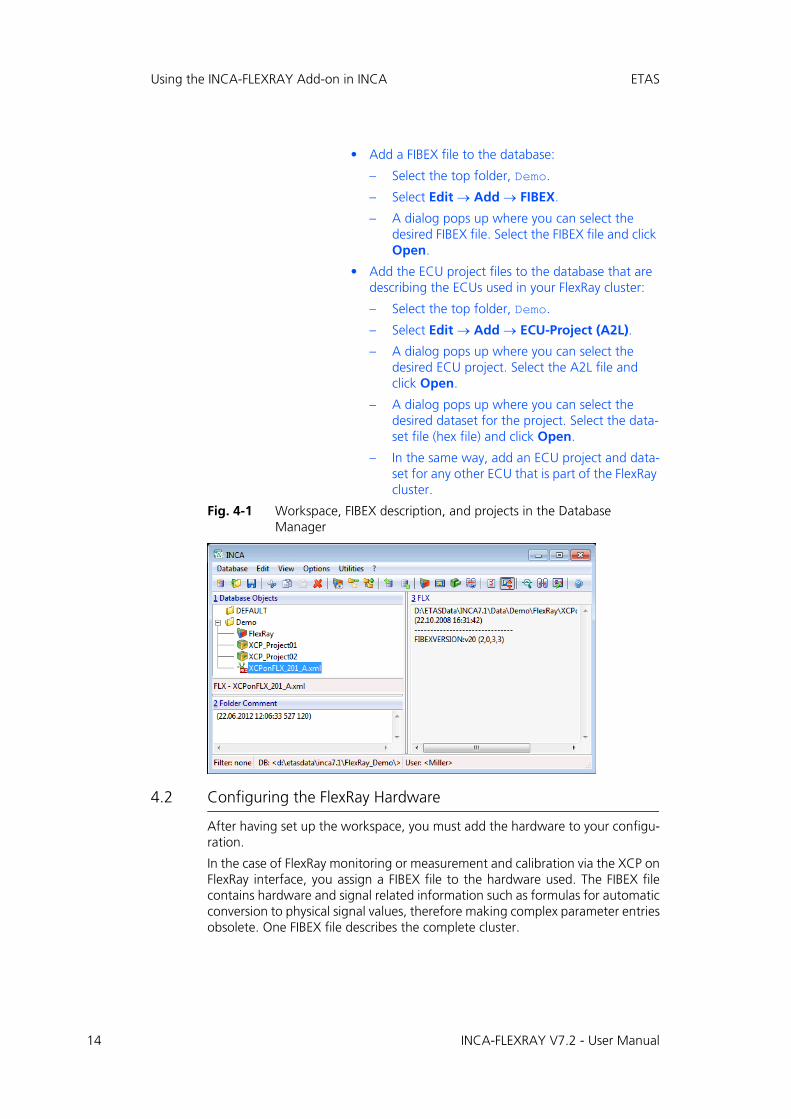
• Add a FIBEX file to the database:
– Select the top folder, Demo.
– Select Edit Add FIBEX.
– A dialog pops up where you can select the desired FIBEX file. Select the FIBEX file and click Open.
• Add the ECU project files to the database that are describing the ECUs used in your FlexRay cluster:
– Select the top folder, Demo.
– Select Edit Add ECU-Project (A2L).
– A dialog pops up where you can select the desired ECU project. Select the A2L file and click Open.
– A dialog pops up where you can select the desired dataset for the project. Select the data-set file (hex file) and click Open.
– In the same way, add an ECU project and data-set for any other ECU that is part of the FlexRay cluster.
Fig. 4-1 Workspace, FIBEX description, and projects in the Database Manager
4.2 Configuring the FlexRay Hardware
After having set up the workspace, you must add the hardware to your configu-ration.
In the case of FlexRay monitoring or measurement and calibration via the XCP onFlexRay interface, you assign a FIBEX file to the hardware used. The FIBEX filecontains hardware and signal related information such as formulas for automaticconversion to physical signal values, therefore making complex parameter entriesobsolete. One FIBEX file describes the complete cluster.
INCA-FLEXRAY V7.2 - User Manual
ETAS Using the INCA-FLEXRAY Add-on in INCA
For the XCP devices, you assign an ECU project file to the hardware used. TheECU project file describes the available buffers for the XCP protocol for an ECU.There must be one ECU project file for each ECU.
The following sections describe the hardware configuration separately for Flex-Ray Monitoring and for measurement and calibration via XCP on FlexRay.
4.2.1 Configuring the FlexRay Hardware for FlexRay Monitoring
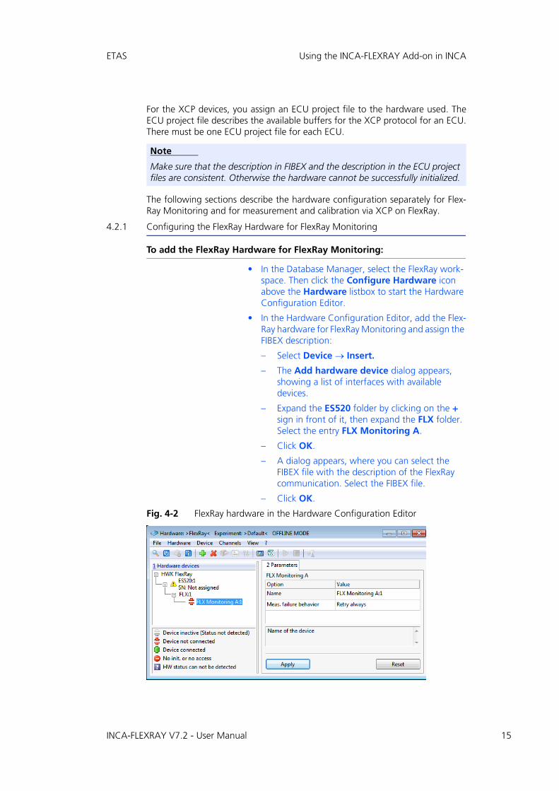
To add the FlexRay Hardware for FlexRay Monitoring:
• In the Database Manager, select the FlexRay work-space. Then click the Configure Hardware icon above the Hardware listbox to start the Hardware Configuration Editor.
• In the Hardware Configuration Editor, add the Flex-Ray hardware for FlexRay Monitoring and assign the FIBEX description:
– Select Device Insert.
– The Add hardware device dialog appears, showing a list of interfaces with available devices.
– Expand the ES520 folder by clicking on the + sign in front of it, then expand the FLX folder. Select the entry FLX Monitoring A.
– Click OK.
– A dialog appears, where you can select the FIBEX file with the description of the FlexRay communication. Select the FIBEX file.
– Click OK.
Fig. 4-2 FlexRay hardware in the Hardware Configuration Editor
Note
Make sure that the description in FIBEX and the description in the ECU project files are consistent. Otherwise the hardware cannot be successfully initialized.
INCA-FLEXRAY V7.2 - User Manual 15

16
Using the INCA-FLEXRAY Add-on in INCA ETAS
In the following section you first get some more background information aboutconfiguring the FlexRay controller before continuing with the step by stepinstruction on page 17.
One FlexRay bus consists of two physical channels: channel A and channel B. OneFlexRay controller on a controller handles both channels A and B. The channelsare not independent. All controllers connected to one net represent one 'cluster'.
INCA receives all frames on both FlexRay channels of all interfaces connected toINCA. It can monitor 1 to 4 FlexRay clusters in parallel (i.e. 1 to 8 FlexRay chan-nels).
In the next step, after having selected the FLX:1 controller in the Hardwaredevices list, you can select a controller for the configuration of the INCA Flexrayhardware interface. The Controller drop down list contains all controllers thatare defined in the FIBEX description file1.
Finally, you define which controller will be used for FlexRay startup.
The FlexRay specification requires that for safety reasons, a FlexRay cluster musthave at least three startup controllers. The FlexRay cluster still works with twostartup controllers. The ES520 monitoring device also works in clusters whereonly one startup controller is present, because it is able to represent the secondstartup controller itself.
The number behind the string STARTUP describes the slot ID (KEY_SLOT_ID) indecimal representation that is used for sending the startup information. Byselecting such a controller, you determine that INCA represents the secondstartup controller, which enables INCA to monitor communication on a FlexRaynetwork in environments with only one physical startup controller.
1. FlexRay knows three different types of controllers:• Startup controllers: controllers that are used for startup of the FlexRay net-
work. Startup controllers are listed in FIBEX and therefore also in INCA with the appendix "STARTUP nn", where nn represents the slot ID used for sending the startup information.
Example for notation in FIBEX:<flexray:STARTUP-SYNC>60</flexray:STARTUP-SYNC>
• Sync controllers: controllers that are used for time synchronization of the controllers in the network. Sync controllers are listed in FIBEX and there-fore also in INCA with the appendix "SYNC nn", where nn represents the slot ID used for sending the sync information. Startup controllers are always also sync controllers and can be used as such.
Example for notation in FIBEX:<flexray:SYNC>89</flexray:SYNC>
• Integration controllers: all other controllers, which can be used to config-ure FlexRay monitoring. The names of integration controllers are not spe-cifically indexed.
Example for notation in FIBEX:<flexray:NONE/>
INCA-FLEXRAY V7.2 - User Manual
ETAS Using the INCA-FLEXRAY Add-on in INCA
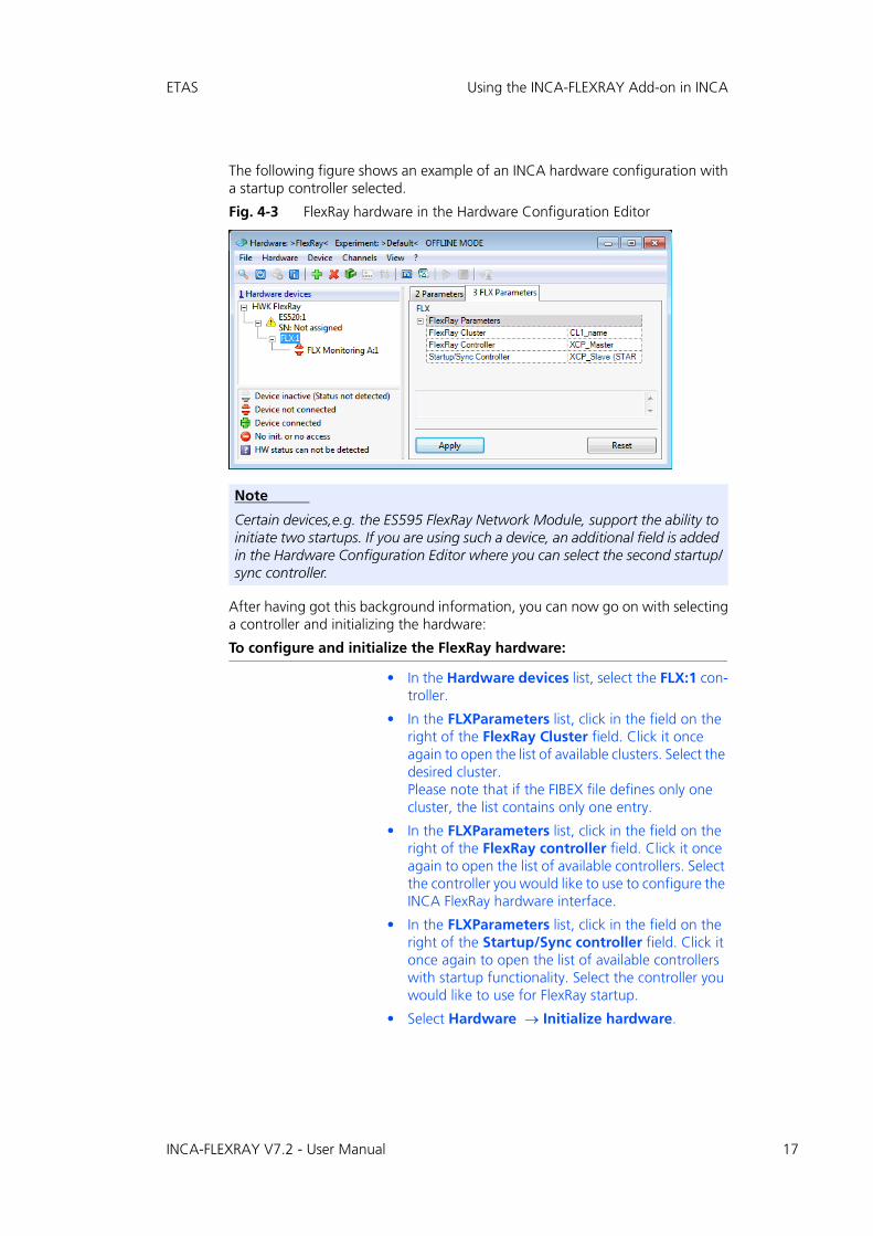
The following figure shows an example of an INCA hardware configuration witha startup controller selected.
Fig. 4-3 FlexRay hardware in the Hardware Configuration Editor
After having got this background information, you can now go on with selectinga controller and initializing the hardware:
To configure and initialize the FlexRay hardware:
• In the Hardware devices list, select the FLX:1 con-troller.
• In the FLXParameters list, click in the field on the right of the FlexRay Cluster field. Click it once again to open the list of available clusters. Select the desired cluster.Please note that if the FIBEX file defines only one cluster, the list contains only one entry.
• In the FLXParameters list, click in the field on the right of the FlexRay controller field. Click it once again to open the list of available controllers. Select the controller you would like to use to configure the INCA FlexRay hardware interface.
• In the FLXParameters list, click in the field on the right of the Startup/Sync controller field. Click it once again to open the list of available controllers with startup functionality. Select the controller you would like to use for FlexRay startup.
• Select Hardware Initialize hardware.
Note
Certain devices,e.g. the ES595 FlexRay Network Module, support the ability to initiate two startups. If you are using such a device, an additional field is added in the Hardware Configuration Editor where you can select the second startup/sync controller.
INCA-FLEXRAY V7.2 - User Manual 17
18
Using the INCA-FLEXRAY Add-on in INCA ETAS
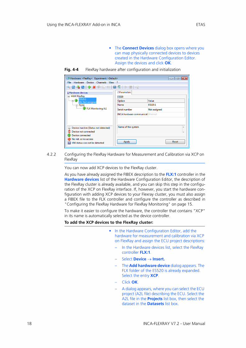
• The Connect Devices dialog box opens where you can map physically connected devices to devices created in the Hardware Configuration Editor. Assign the devices and click OK.
Fig. 4-4 FlexRay hardware after configuration and initialization
4.2.2 Configuring the FlexRay Hardware for Measurement and Calibration via XCP on FlexRay
You can now add XCP devices to the FlexRay cluster.
As you have already assigned the FIBEX description to the FLX:1 controller in theHardware devices list of the Hardware Configuration Editor, the description ofthe FlexRay cluster is already available, and you can skip this step in the configu-ration of the XCP on FlexRay interface. If, however, you start the hardware con-figuration with adding XCP devices to your Flexray cluster, you must also assigna FIBEX file to the FLX controller and configure the controller as described in"Configuring the FlexRay Hardware for FlexRay Monitoring" on page 15.
To make it easier to configure the hardware, the controller that contains "XCP"in its name is automatically selected as the device controller.
To add the XCP devices to the FlexRay cluster:
• In the Hardware Configuration Editor, add the hardware for measurement and calibration via XCP on FlexRay and assign the ECU project descriptions:
– In the Hardware devices list, select the FlexRay controller FLX:1.
– Select Device Insert.
– The Add hardware device dialog appears. The FLX folder of the ES520 is already expanded. Select the entry XCP.
– Click OK.
– A dialog appears, where you can select the ECU project (A2L file) describing the ECU. Select the A2L file in the Projects list box, then select the dataset in the Datasets list box.
INCA-FLEXRAY V7.2 - User Manual
ETAS Using the INCA-FLEXRAY Add-on in INCA
– Click OK.
– In the same way, add an XCP device for any other ECU that is part of the FlexRay cluster.
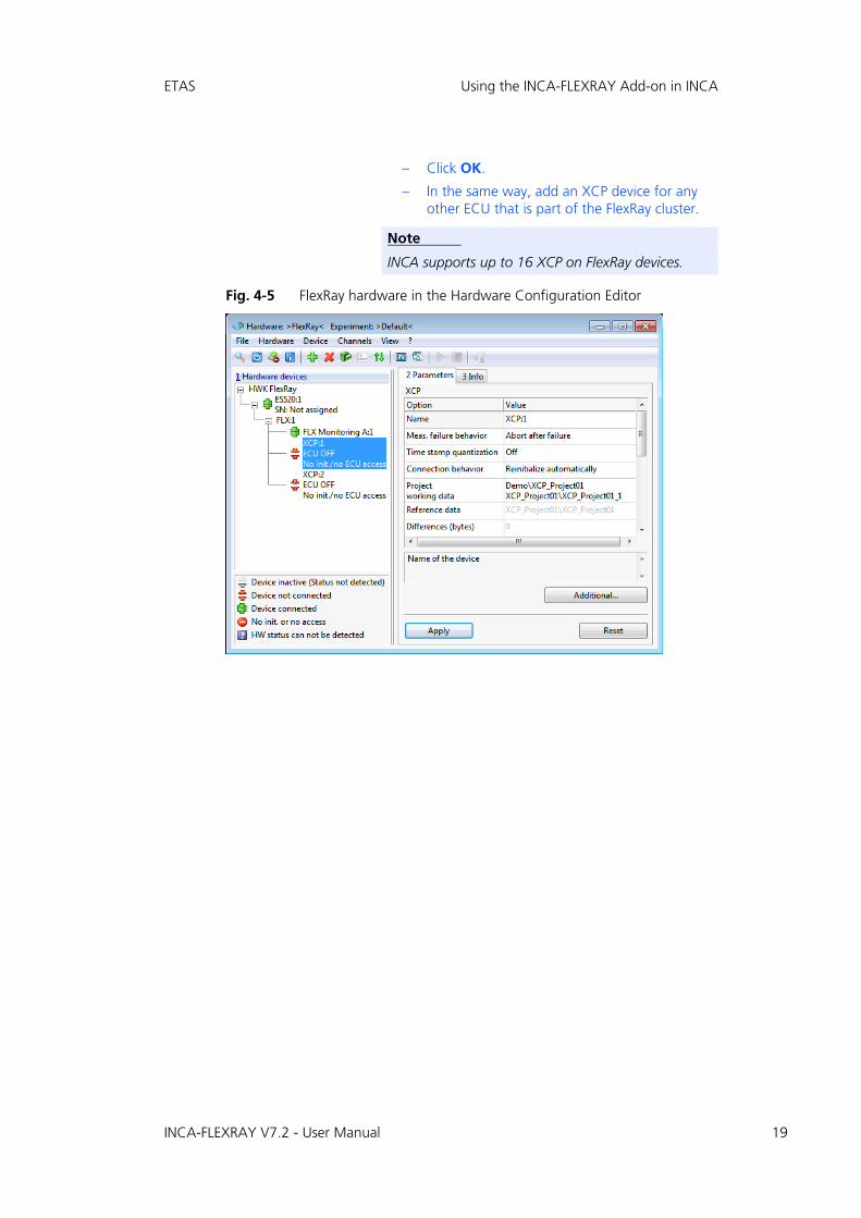
Fig. 4-5 FlexRay hardware in the Hardware Configuration Editor
Note
INCA supports up to 16 XCP on FlexRay devices.
INCA-FLEXRAY V7.2 - User Manual 19
20
Using the INCA-FLEXRAY Add-on in INCA ETAS
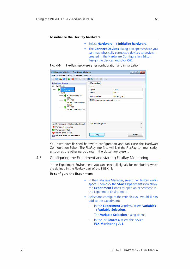
To initialize the FlexRay hardware:
• Select Hardware Initialize hardware.
• The Connect Devices dialog box opens where you can map physically connected devices to devices created in the Hardware Configuration Editor. Assign the devices and click OK.
Fig. 4-6 FlexRay hardware after configuration and initialization
You have now finished hardware configuration and can close the HardwareConfiguration Editor. The FlexRay interface will join the FlexRay communicationas soon as the other participants in the cluster are present.
4.3 Configuring the Experiment and starting FlexRay Monitoring
In the Experiment Environment you can select all signals for monitoring whichare defined in the FlexRay part of the FIBEX file.
To configure the Experiment:
• In the Database Manager, select the FlexRay work-space. Then click the Start Experiment icon above the Experiment listbox to open an experiment in the Experiment Environment.
• Select and configure the variables you would like to add to the experiment:
– In the Experiment window, select Variables Variable Selection.
The Variable Selection dialog opens.
– In the list Sources, select the device FLX Monitoring A:1.
INCA-FLEXRAY V7.2 - User Manual
ETAS Using the INCA-FLEXRAY Add-on in INCA
The variables list now shows all variables in alphabetical order that belong to thisdevice. It might happen that you do not see the variables that you expect or thatthere are no variables displayed at all; in this case please verify that there is nofilter being used. If required, you can deactivate all filters by clicking on the Clearall filters icon in the toolbar.
If you are interested only in variables for individual functions, you can expand thetree in the Sources list by clicking on the + sign left of the device and select onlythe desired functions. The variables list only displays the variables of the selectedfunctions. Depending on the definition in the FIBEX file, signals might also begrouped by frame, ECU or signal groups (see "Selecting Variables by Frame, ECUor Signal Group" on page 25). Summarizing these explanations, you can selectvariables in one of the following ways:
• You click on the FlexRay device and select the desired signals from a com-plete list of signals for that device.
• You expand the tree structure of the FlexRay device by clicking on the + sign in front of it, click on a function and select the desired variables from a list of signals associated with that function.For both devices and functions, the same icon representing a devices hierarchy is used in the tree view of the Sources list.
• You expand the tree structure of the FlexRay device by clicking on the + sign in front of it, further expand one of the groups for frames, ECUs or signal groups and click on the desired items. Afterwards you can select the desired variables from a subset containing signals associated with the selected frames, ECUs or signal groups. Groups are represented by the following icon in the tree view of the Sources list:
• In the variables list, select all variables you would like to monitor.
Please note that further information is displayed in the information pane of the dialog as soon as you select a variable.
• In the list Sources, select one of the XCP device that you have added to your workspace.
• In the variables list, select all variables you would like to measure or calibrate.
• Click OK to add the selected variables to the Exper-iment window.
• Select Experiment Save.
The Save as dialog appears. In the list Database Objects select the Demo folder to add the experi-ment to the folder. Then enter the name Moni-toring_Exp in the list Item name and click OK.
To start Monitoring / Measuring:
• Click <F11> to start visualization without recording
or
• Click <F12> to start recording.
INCA-FLEXRAY V7.2 - User Manual 21

22
Using the INCA-FLEXRAY Add-on in INCA ETAS
To start Calibrating:
• Make sure that the Working Page is activated.
• Perform your calibration tasks as usual.
For detailed information on how to perform calibration tasks please see the INCAtutorial.
INCA-FLEXRAY V7.2 - User Manual
ETAS Appendix
5 Appendix
This chapter gives some information on technical restrictions and provides helpfor trouble-shooting as well as tips and tricks for selected tasks.
5.1 Restrictions
This product has been manufactured with the utmost care for quality, usabilityand completeness in terms of users’ expectations.
Nevertheless there are constraints that need to be considered when using thisproduct.
5.1.1 Some FIBEX Data Types are not supported
INCA supports all signal data types usually used. This includes data types of up to32 bit and float 64 data types.
Some minor data types are not supported in INCA and therefore removed fromthe imported FIBEX file:
• Signals with data types longer than 32 bit (A_UINT64, A_INT64)
• Signals with the data type A_UNICODE2STRING
• Signals with the data type A_BYTEFIELD
• Signals with the data type A_BITFIELD
• Signals with the data type OTHER
The .log files for the FIBEX import report any removal of data types from theFIBEX file.
5.1.2 Data with FlexRay PreambleIndicatorBit Set is Discarded
The FlexRay specification defines a preamble indicator bit for NetworkManage-ment and special filtering applications.
INCA-FLEXRAY discards the data of FlexRay frames where the preamble indicatorbit is set:
• The NetworkManagement information is neither captured nor used.
• Message filtering in the dynamic segment is not applied.
• The log file A1b_FlexRayMon.log logs events where data was discarded.
5.1.3 FlexRay Network temporarily shuts down on Hardware Initialization
The add-On INCA-FLEXRAY is able to represent one startup/sync controller in aFlexRay network.
In cases where only two startup/sync controllers are present in the connectedcluster a re-initialization of the measurement hardware will result in a temporaryshutdown of the FlexRay network.
5.1.4 FlexRay Bus Load leads to PC Overload
FlexRay delivers a high amount of data to measurement systems.
Multiple FlexRay channels with high bus load may lead to an overload situationfor the PC.
The following setup is recommended to avoid overload situations:
• 3 GHz PC in idle mode (no further task or measurement)
INCA-FLEXRAY V7.2 - User Manual 23

24
Appendix ETAS
5.1.5 ASAM MCD-3 (new)1 / ASAP3
When using the remote control functionality (ASAM-MCD3 MCD or ASAP3) youneed to select "FRAME AVAILABLE" from the available rasters to monitor Flex-Ray signals.
5.1.6 Flashing and Diagnosis over the XCP Interface are not Supported
The XCP on FlexRay interface only supports measurement and calibration usecases; flash programming and diagnosis are not supported. If you need to flashcode and/or data to the ECU, you can use other flash ports according to yoursystem configuration.
1. ASAM MCD 3 V2.00.02 (object-oriented model), dating from 04.04.2005
INCA-FLEXRAY V7.2 - User Manual
ETAS Appendix
5.2 Tips and Tricks
This section provides some help information for tasks which might be difficult tounderstand or can be optimized by means of little tips and tricks.
5.2.1 Selecting Variables by Frame, ECU or Signal Group
When you determine which variables are to be used in the INCA ExperimentEnvironment for measurement and calibration tasks, you usually first select adevice or a function of that device and then select the desired variables from aplain list in the "Variable Selection" dialog.
In case of CAN Monitoring devices, the variables are also grouped by CANframes so that you can either select the variables from a list of all variables orfrom a sub-list of variables belonging only to the selected CAN frame.
According to the same principle, the variables of a FlexRay device can be groupedby one of the following categories:
• Grouping by frames:When you select a frame in the Sources list, the variables list shows all signals located in the selected frame.
• Grouping by ECUs:When you select an ECU in the Sources list, the variables list shows all TX-signals of the selected ECU (i.e. signals that are sent by the ECU).
• Grouping by signal groups1:When you select a signal group in the Sources list, the variables list shows all signals that are part of the selected signal group.
Note
Depending on the description in the FIBEX file, the same signal can occur in different frames
1. In this context the term "signal group" refers to the signal groups as specified in the FIBEX file in the <requirements> section. FIBEX specifies that all sig-nals of a signal group must be located in one frame.
Note
Only those groupings are available in the "Variable Selection" dialog that are defined in the FIBEX file provided by the vehicle manufacturer. If the FIBEX file does not contain any of these groups, the FlexRay device does not contain any branches for groups in the Sources tree structure, and the variables belonging to the FlexRay device can only be selected from a plain list.
INCA-FLEXRAY V7.2 - User Manual 25

26
Appendix ETAS
In the "Variable Selection" dialog, each group is depicted by the following icon: (see also screenshot below):
INCA-FLEXRAY V7.2 - User Manual

INCA-FLEXRAY V7.2 - User Manual 27
ETAS ETAS Contact Addresses
6 ETAS Contact Addresses
ETAS HQ
ETAS GmbH
ETAS Subsidiaries and Technical Support
For details of your local sales office as well as your local technical support teamand product hotlines, take a look at the ETAS website:
Borsigstraße 14 Phone: +49 711 3423-0
70469 Stuttgart Fax: +49 711 3423-2106
Germany WWW: www.etas.com
ETAS subsidiaries WWW: www.etas.com/en/contact.php
ETAS technical support WWW: www.etas.com/en/hotlines.php