in049-26 abbreviations used in this · pdf filea/t automatic transmission ... detent spring...
TRANSCRIPT

IN049-26
-INTRODUCTION TERMSIN-5
5Author�: Date�:
A650E AT (RM780U)
TERMSABBREVIATIONS USED IN THIS MANUAL
Abbreviations Meaning
A/T Automatic Transmission
ATF Automatic Transmission Fluid
B0 Overdrive Brake
B1 3rd Coast Brake
B2 3rd Brake
B3 2nd Brake
B4 1st & Reverse Brake
C0 Overdrive Direct Clutch
C1 Forward Clutch
C2 Direct Clutch
D Disc
F Flange
F0 Overdrive One-way Clutch
F1 No. 1 One-way Clutch
F2 No. 2 One-way Clutch
FIPG Formed in Place Gasket
MP Multipurose
O/D Overdrive
P Plate
S1 Shift Solenoid Valve No. 1
S2 Shift Solenoid Valve No. 2
S3 Shift Solenoid Valve No. 3
S4 Shift Solenoid Valve No. 4
SSM Special Service Materials
SST Special Service Tools
w/ with
w/o without
WWW.ALL-TR
ANS.BY

AT04F-02
D01296
Pin E-Ring
Spring
Retainer
Spring
O-Ring
Piston Rod
Oil Seal Ring
Piston
E-RingCover
Snap Ring�
Non-reusable part�
3rd Coast Brake Band
-AUTOMATIC TRANSMISSION THIRD COAST BRAKEAT-45
68Author�: Date�:
A650E AT (RM780U)
THIRD COAST BRAKECOMPONENTS
WWW.ALL-TR
ANS.BY

AT04N-02
D09433
Snap Ring
Flange
Flange
Snap Ring
Piston Return Spring
O-Ring
O/D Brake PistonO/D Support
Thrust Washer
Oil Seal
�
�
Non-reusable part
Disc
Plate
-AUTOMATIC TRANSMISSION OVERDRIVE BRAKEAT-49
72Author�: Date�:
A650E AT (RM780U)
OVERDRIVE BRAKECOMPONENTS
WWW.ALL-TR
ANS.BY

AT05H-02
D01250
Shift Solenoid Valve SLU
Shift Solenoid Valve SLN
Shift Solenoid Valve No. 3Shift Solenoid Valve No. 1
Shift SolenoidValve No. 2
Shift SolenoidValve No. 4
Spring Plate
DetentSpring
Manual Valve
Pressure ReliefValve Spring Seat
6.4 (65, 56 in.·lbf)
No. 1 Lock Plate
No. 2 Lock Plate
SpringBall
N·m (kgf·cm, ft·lbf) : Specified torque
Shift Solenoid Valve SLT
�
�
�
�
�
�
O-Ring
Non-reusable part�
Oil Guide Plate
9.8 (100, 7)
9.8 (100, 7)
9.8 (100, 7)
9.8 (100, 7)
6.4 (65, 56 in.·lbf)
9.8 (100, 7)
9.8 (100, 7)
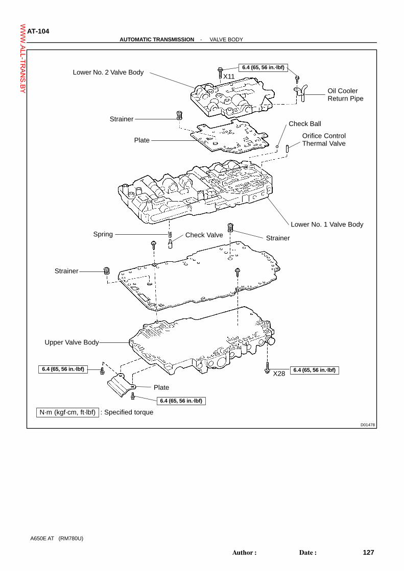
-AUTOMATIC TRANSMISSION VALVE BODYAT-103
126Author�: Date�:
A650E AT (RM780U)
VALVE BODYCOMPONENTS
WWW.ALL-TR
ANS.BY
D01478
Lower No. 2 Valve Body
Strainer
PlateOrifice ControlThermal Valve
Lower No. 1 Valve Body
Check Valve
Upper Valve Body
Spring
6.4 (65, 56 in.·lbf)
Strainer
Strainer
6.4 (65, 56 in.·lbf)
N·m (kgf·cm, ft·lbf) : Specified torque
Oil CoolerReturn Pipe
Check Ball
X28
X11
6.4 (65, 56 in.·lbf)
6.4 (65, 56 in.·lbf)
Plate
AT-104-AUTOMATIC TRANSMISSION VALVE BODY
127Author�: Date�:
A650E AT (RM780U)
WWW.ALL-TR
ANS.BY

AT05K-01
D01258
Retainer
Plug
C-1 Orifice ControlValve
Plug
RetainerPlug
C-1 Accumulator Valve
Solenoid Modulator Valve
Check Valve
Retainer
RetainerRetainerPlug
Lock-up Relay Valve
C-0 Exhaust Valve
4-5 Shift Valve
Coast Brake Control Valve
Retainer
Plunger
Sleeve
Plug
RetainerRetainer
Plug
Plunger
Sleeve
Retainer
Secondary Regulator Valve
Retainer
2-3 Shift Valve
Strainer
Strainer
Plug
Retainer
Sleeve
Plunger
B-3 Control Valve
Plate
-AUTOMATIC TRANSMISSION UPPER VALVE BODYAT-1 13
136Author�: Date�:
A650E AT (RM780U)
COMPONENTS
WWW.ALL-TR
ANS.BY

AT05M-01
D01256
Check Valve
3-4 Shift Valve
PlugRetainer
1-2 Shift ValveRetainer
Plug
Retainer
B-2 Release Control Valve
Primary Regulator Valve
Plunger
Sleeve
Retainer
Cut Back Valve
Retainer
Plug
Retainer
Accumulator Control Valve
Plunger
Sleeve
Retainer
Solenoid Relay Valve
Retainer
Plug
Retainer
C-0 Control Relay Valve
Lock-up Control Valve
Sleeve
Retainer
Plunger
Plug
Strainer
-AUTOMATIC TRANSMISSION LOWER NO.1 VALVE BODYAT-1 17
140Author�: Date�:
A650E AT (RM780U)
COMPONENTS
WWW.ALL-TR
ANS.BY

AT05O-01
D01257
Retainer
Plug
Spring
Reverse Control Valve
AT-120-AUTOMATIC TRANSMISSION LOWER NO.2 VALVE BODY
143Author�: Date�:
A650E AT (RM780U)
COMPONENTS
WWW.ALL-TR
ANS.BY

AT05Q-02
D09414
Adjusting Bolt
Park/NeutralPosition Switch
TransmissionWire
TransmissionCase
Union
Extension Housing
Vehicle Speed SensorRotor
�
TransmissionHousing
Oil Seal
16 (160, 12)
5.4 (55, 48 in.·lbf)
57 (580, 42)
Parking LockPawl Bracket
Parking Lock Pawl
Parking Lock Pawl Shaft
C2 Accumulator Piston
B0 Accumulator PistonValve Body
Spring
Check Ball Body
9.8 (100, 7)
Oil Strainer
Magnet
Oil Pan
�
Drain Plug20 (205,15)
N·m (kgf·cm, ft·lbf)
Non-reusable part
: Specified torque
�
�
6.9 (70, 61 in.·lbf)
7.4 (75, 65 in.·lbf)
Manual Valve Lever Shaft
Parking Lock Rod
Manual Valve LeverSpacer
5.4 (55, 48 in.·lbf)
X4
29 (300, 22)
�
�
X20
X18
34 (345, 25)
� O-Ring
B2 Accumulator Piston�
�
�
�SpringC0 Accumulator Piston
Spring Pin
�
13 (130, 9)
5.4 (55, 48 in.·lbf)
O/D Direct ClutchSpeed Sensor
�
�
Gasket
Oil Seal�
�
E-Ring
StopperPlate
7.4 (75, 65 in.·lbf)
Elbow29 (300, 22)
Vehicle SpeedSensor
Lock Washer
7.4 (75, 65 in.·lbf)�
Spring
Snap Ring
�
9.8 (100, 7)
Breather Hose
Control Shaft Lever
Key
�
�
�Gasket
5.4 (55, 48 in.·lbf)
34 (345, 25)
X6
�
-AUTOMATIC TRANSMISSION COMPONENT PARTSAT-3
26Author�: Date�:
A650E AT (RM780U)
COMPONENT PARTSCOMPONENTS
WWW.ALL-TR
ANS.BY

D09454
Oil Pump
O-Ring�
Race
AssembledBearing & Race O/D Planetary Gear Unit with
O/D Direct Clutch
O/D Brake PackBearing
Race
Race
O/D Support
Direct ClutchAssembledBearing & Race Thrust Washer
21 (215, 16)
O/D PlanetaryRing Gear
Thrust Washer
Forward Clutch
3rd CoastBrake Band
Bearing
E-RingPin
AssembledBearing & Race
Race
Forward ClutchHub
Race
2nd Brake Pack
Front Planetary Gear
Front & CenterPlanetary Sun Gear
Rear PlanetaryRing Gear
3rd Coast BrakePiston
3rd CoastBrake Cover
Brake DrumGasket
�
Output Shaftwith Center & RearPlanetary Gear
No. 2 One-wayClutch
Spring
Snap Ring
Washer
Thrust Washer
AssembledBearing & Race
Race
N·m (kgf·cm, ft·lbf)Non-reusable part�
: Specified torque
X7
No. 1 One-wayClutch
Multiple DiscBrakeSnap RingSun Gear
Input Drum
ThrustWasher
Snap Ring
O-Ring
�
Spring
Snap Ring
Snap Ring
Retainer
Bearing
Spring
AssembledBearing & Race
25 (260, 19)
AT-4-AUTOMATIC TRANSMISSION COMPONENT PARTS
27Author�: Date�:
A650E AT (RM780U)
WWW.ALL-TR
ANS.BY

AT04B-02
D01280
Oil Pump Body
Oil Pump Drive Gear
Stator Shaft
Oil Seal Ring
Oil Pump Driven Gear
� Oil Seal
N·m (kgf·cm, ft·lbf)
� Non-reusable part
: Specified torque
X13
10 (100, 7)
� O-Ring
AT-40-AUTOMATIC TRANSMISSION OIL PUMP
63Author�: Date�:
A650E AT (RM780U)
OIL PUMPCOMPONENTS
WWW.ALL-TR
ANS.BY

AT04J-02
D01414
O/D Direct Clutch Drum
O/D Direct Clutch Piston
O/D Planetary Gear
O-Ring
Snap Ring
Plate
Disc
Flange
Snap Ring
�
Piston Return Spring
Snap Ring
Snap Ring
Retaining PlateO/D One-wayClutch
One-way ClutchOuter Race
Bearing
O/D PlanetaryRing Gear
Race
Thrust WasherOne-way ClutchInner Race
Ring Gear Flange
� Non-reusable part
Plate
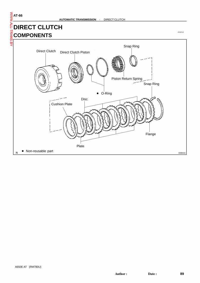
-AUTOMATIC TRANSMISSION OVERDRIVE DIRECT CLUTCHAT-55
78Author�: Date�:
A650E AT (RM780U)
OVERDRIVE DIRECT CLUTCHCOMPONENTS
WWW.ALL-TR
ANS.BY
AT04R-02
D09441
Snap Ring
Piston Return Spring
� O-Ring
Disc
Plate
Flange
Snap Ring
� Non-reusable part
Direct Clutch Direct Clutch Piston
Cushion Plate
AT-66-AUTOMATIC TRANSMISSION DIRECT CLUTCH
89Author�: Date�:
A650E AT (RM780U)
DIRECT CLUTCHCOMPONENTS
WWW.ALL-TR
ANS.BY

AT04V-02
D09444
Oil Seal Ring
Forward Clutch
Forward Clutch Piston
Return Spring
Snap Ring
Bearing
O-Ring
Disc
Flange
Snap Ring
�
�
Non-reusable part
Plate
Cushion Plate
AT-72-AUTOMATIC TRANSMISSION FORWARD CLUTCH
95Author�: Date�:
A650E AT (RM780U)
FORWARD CLUTCHCOMPONENTS
WWW.ALL-TR
ANS.BY

AT04Z-02
D09447
No. 1 One-way Clutch
Flange
Snap Ring
Plate
Disc
Piston Return Spring
Retainer
3rd Brake Piston
� O-Ring
Brake Drum
2nd Brake Piston
Washer
Front Planetary Gear
Front & Center PlanetarySun Gear
� Non-reusable part
Snap Ring
� O-Ring
� O-Ring
Washer
AT-78-AUTOMATIC TRANSMISSION MULTIPLE DISC BRAKE
101Author�: Date�:
A650E AT (RM780U)
MULTIPLE DISC BRAKECOMPONENTS
WWW.ALL-TR
ANS.BY

AT053-01
D01473
Front PlanetaryRing Gear
Snap Ring
Center Planetary Gear
Center PlanetaryRing Gear
Bearing
Race
Intermediate Shaft
Output Shaft withRear Planetary Gear
Snap Ring
-AUTOMATIC TRANSMISSION CENTER PLANETARY GEARAT-85
108Author�: Date�:
A650E AT (RM780U)
CENTER PLANETARY GEARCOMPONENTS
WWW.ALL-TR
ANS.BY

AT057-01
D01475
Output Shaft withRear Planetary Gear
Rear PlanetaryRing Gear
Rear PlanetaryRing Gear Flange
Snap Ring
Rear PlanetarySun Gear
-AUTOMATIC TRANSMISSION REAR PLANETARY GEARAT-89
112Author�: Date�:
A650E AT (RM780U)
REAR PLANETARY GEARCOMPONENTS
WWW.ALL-TR
ANS.BY

AT05B-02
D09451
Snap Ring
Flange
Snap Ring
Piston Return Spring
No. 2 Brake Piston
Reaction SleeveNo. 1 Brake Piston
� O-Ring
� Non-reusable part
Plate
Disc
-AUTOMATIC TRANSMISSION FIRST AND REVERSE BRAKEAT-93
116Author�: Date�:
A650E AT (RM780U)
FIRST AND REVERSE BRAKECOMPONENTS
WWW.ALL-TR
ANS.BY

AT0Y1-01
D09426Non-reusable part�
� Oil Seal
Dust Deflector
Extension Housing
�
-AUTOMATIC TRANSMISSION EXTENSION HOUSINGAT-99
122Author�: Date�:
A650E AT (RM780U)
EXTENSION HOUSINGCOMPONENTS
WWW.ALL-TR
ANS.BY
AT04G-01
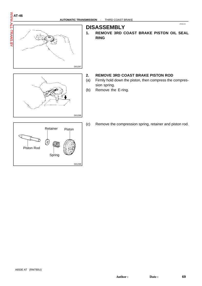
D01297
D01298
D01299
Piston
Spring
Retainer
Piston Rod
AT-46-AUTOMATIC TRANSMISSION THIRD COAST BRAKE
69Author�: Date�:
A650E AT (RM780U)
DISASSEMBLY1. REMOVE 3RD COAST BRAKE PISTON OIL SEAL
RING
2. REMOVE 3RD COAST BRAKE PISTON ROD(a) Firmly hold down the piston, then compress the compres-
sion spring.(b) Remove the E-ring.
(c) Remove the compression spring, retainer and piston rod.
WWW.ALL-TR
ANS.BY

AT04O-02
D01332
D01333
D01334
D09434
SST
D01432
AT-50-AUTOMATIC TRANSMISSION OVERDRIVE BRAKE
73Author�: Date�:
A650E AT (RM780U)
DISASSEMBLY1. CHECK PISTON OPERATION OF O/D BRAKE(a) Place the O/D support assembly onto the direct clutch as-
sembly.
(b) Apply compressed air (392 kPa, 4 kgf/cm2, 57 psi) into theoil passage and be sure that the O/D brake piston movessmoothly.
2. REMOVE CLUTCH DRUM THRUST WASHER FROMO/D SUPPORT
3. REMOVE PISTON RETURN SPRING(a) Place SST on the spring retainer, and compress the re-
turn spring with a press.SST 09387-00100
(b) Remove the snap ring with a screwdriver.(c) Remove the piston return spring.
4. REMOVE O/D BRAKE PISTON(a) Place the O/D support onto the direct clutch assembly.(b) Hold the O/D brake piston so it does not slant, and apply
compressed air (392 kPa, 4 kgf/cm2, 57 psi) into the pas-sage to remove the O/D brake piston.
(c) Remove the O/D brake piston.
WWW.ALL-TR
ANS.BY

D01336
O-Ring
O-Ring
D01337
-AUTOMATIC TRANSMISSION OVERDRIVE BRAKEAT-51
74Author�: Date�:
A650E AT (RM780U)
(d) Remove the 2 O-rings.
5. REMOVE 2 OIL SEAL RINGS
WWW.ALL-TR
ANS.BY

AT05I-02
D01249
D01248
Manual Valve
D01247
(a)(b)
(c)
(d)
(e)
(g)
(h)
D01251
Oil CoolerReturn Pipe
Clamp
-AUTOMATIC TRANSMISSION VALVE BODYAT-105
128Author�: Date�:
A650E AT (RM780U)
DISASSEMBLY1. REMOVE DETENT SPRING AND SPRING PLATERemove the bolt, detent spring and spring plate.
2. REMOVE MANUAL VALVE
3. REMOVE 7 SOLENOIDS(a) Remove the bolt and shift solenoid valve No. 1.(b) Remove the bolt and shift solenoid valve No. 3.(c) Remove the bolt and shift solenoid valve No. 2.(d) Remove the bolt and shift solenoid valve No. 4.(e) Remove the bolt, No. 2 lock plate and shift solenoid valve
SLN.(f) Remove the oil guide plate.(g) Remove the bolt, No. 1 lock plate and shift solenoid valve
SLU, SLT.(h) Remove the bolt, pressure relief valve spring seat, spring
and ball.(i) Remove the 6 O-rings from shift solenoid valve No. 1, No.
2, No. 3 and No. 4.
4. REMOVE LOWER NO. 2 VALVE BODY(a) Remove the 12 bolts. 2 of them are attached to the oil
cooler return pipe and clamp. So remove them all togeth-er.
WWW.ALL-TR
ANS.BY

D01252
Plate
Lower No. 2Valve Body
D01261
Check Ball
Orifice ControlThermal Valve
D01253
D01254
D01259
Plate
AT-106-AUTOMATIC TRANSMISSION VALVE BODY
129Author�: Date�:
A650E AT (RM780U)
(b) Remove the lower No. 2 valve body.(c) Remove the plate.(d) Remove the strainer.
(e) Remove the orifice control thermal valve and check ball.
5. REMOVE UPPER VALVE BODY(a) Turn over assembly and remove the 30 bolts.(b) Remove the plate from the upper valve body.
(c) Remove the upper valve body with the plate.(d) Remove the check valve and spring.
(e) Turn over upper valve body, remove the 2 screws andplate.
(f) Remove the 2 strainers.
WWW.ALL-TR
ANS.BY

AT0XZ-01
D09415
D09457
D01108
Union
Elbow
D01111
D01112
-AUTOMATIC TRANSMISSION COMPONENT PARTSAT-5
28Author�: Date�:
A650E AT (RM780U)
DISASSEMBLY1. REMOVE CONTROL SHAFT LEVERRemove the nut, washer and control shaft lever.
2. REMOVE PARK/NEUTRAL POSITION SWITCH(a) Using a screwdriver, unstake the lock washer.(b) Remove the lock washer, nut and bolt.(c) Remove the bolt and park/neutral position switch.
3. REMOVE UNION AND ELBOW(a) Remove the union and elbow.(b) Remove the 2 O-rings from the union and elbow.
4. REMOVE SPEED SENSOR(a) Remove the 2 bolts and 2 speed sensors.(b) Remove the O-ring from each one.
5. REMOVE TRANSMISSION HOUSING(a) Remove the bolt and breather hose.
WWW.ALL-TR
ANS.BY

D09417
D04841
D09387
D01445
SST
D09418
No. 2One-wayClutch
Retainer
AT-6-AUTOMATIC TRANSMISSION COMPONENT PARTS
29Author�: Date�:
A650E AT (RM780U)
(b) Remove the 6 bolts.(c) Remove the transmission housing.
6. REMOVE EXTENSION HOUSING(a) Remove the 6 bolts.(b) Remove the extension housing.HINT:If necessary, tap the extension housing with a plastic hammer.(c) Remove the extension housing gasket.
7. REMOVE SENSOR ROTOR AND KEY(a) Using a snap ring expander, remove the snap ring.(b) Remove the sensor rotor and key.
8. REMOVE ONE-WAY CLUTCH(a) Using SST, remove the snap ring.
SST 09350-30020 (09350-07070)
(b) Remove the No. 2 one-way clutch and the retainer.
WWW.ALL-TR
ANS.BY

D01116
D01126SST
D01124
D09388
D00753
Gasket
-AUTOMATIC TRANSMISSION COMPONENT PARTSAT-7
30Author�: Date�:
A650E AT (RM780U)
9. INSTALL TRANSMISSION CASE ON OVERHAUL AT-TACHMENT
10. REMOVE OIL PANNOTICE:Do not turn the transmission over as this will contaminatethe valve body with any foreign matter at the bottom of thepan.(a) Remove the 19 bolts.
(b) Insert the blade of SST between the transmission caseand oil pan, cut off applied sealer.SST 09032-00100
NOTICE:Be careful not to damage the oil pan flange.
11. EXAMINE PARTICLES IN PANRemove the magnets and use them to collect steel particles.Carefully lock at the foreign matter and particles in the pan andon the magnets to anticipate the type of wear you will find in thetransmission.
� Steel (magnetic): bearing, gear and clutch platewear
� Brass (non-magnetic): bushing wear
12. REMOVE OIL STRAINER(a) Turn over the transmission.(b) Remove the 4 bolts holding the oil strainer to the valve
body.
(c) Remove the 3 gaskets from the oil strainer.
WWW.ALL-TR
ANS.BY

D09389
Clamp
D01122
StopperPlate
D01461
D01128
Check Ball Body
Spring
D01129
AT-8-AUTOMATIC TRANSMISSION COMPONENT PARTS
31Author�: Date�:
A650E AT (RM780U)
13. REMOVE TRANSMISSION WIRE(a) Remove the ATF temperature sensor.(b) Remove the bolt and clamp.(c) Disconnect the 7 connectors from the shift solenoid
valves.
(d) Remove the bolt and stopper plate from the case.(e) Pull the transmission wire out of the transmission case.(f) Remove the O-ring from the grommet.
14. REMOVE VALVE BODY(a) Remove the 20 bolts.(b) Remove the valve body.
15. REMOVE CHECK BALL BODYRemove the check ball body and spring.
16. REMOVE ACCUMULATOR SPRING AND PISTON(a) Applying compressed air to the oil hole, remove the B2
and C2 accumulator pistons and springs.(b) Remove the O-rings from each pistons.NOTICE:Take care as the B 0 and C0 accumulator piston may jumpout.
WWW.ALL-TR
ANS.BY

D01134
D01133
D09419
D01131
D01130
-AUTOMATIC TRANSMISSION COMPONENT PARTSAT-9
32Author�: Date�:
A650E AT (RM780U)
(c) Applying compressed air to the oil hole, remove the B0 ac-cumulator piston and spring.
(d) Remove the O-rings from the piston.NOTICE:Take care as the C 0 accumulator piston may jump out.
(e) Applying compressed air to the oil hole, remove the C0 ac-cumulator piston and spring.
HINT:The C0 accumulator piston is deviated in 2 parts, so if only thetop part is removed, after removing the spring reapply com-pressed air to remove the bottom part.(f) Remove the O-rings from the piston.
17. REMOVE PARKING LOCK ROD AND PAWL(a) Remove the 3 bolts and parking lock pawl bracket.
(b) Disconnect the parking lock rod from the manual valve le-ver.
(c) Pull out the parking lock pawl shaft from the front side,then remove the lock pawl and spring.
(d) Remove the E-ring from the shaft.
WWW.ALL-TR
ANS.BY

D01185
D01184
D01183
D01182
D01181
SST
AT-10-AUTOMATIC TRANSMISSION COMPONENT PARTS
33Author�: Date�:
A650E AT (RM780U)
18. REMOVE MANUAL VALVE LEVER SHAFT(a) Using a hammer and screwdriver, cut off the spacer and
remove it from the shaft.
(b) Using a pin punch and hammer, drive out the spring pin.HINT:Slowly drive out the spring pin so it does not fall into the trans-mission case.(c) Pull the manual valve lever shaft out through the case and
remove the manual valve lever.
(d) Using a screwdriver, remove the 2 oil seals.
19. REMOVE OIL PUMP(a) Remove the 7 bolts holding the oil pump to the transmis-
sion case.
(b) Using SST, remove the oil pump.SST 09350-30020 (09350-07020)
WWW.ALL-TR
ANS.BY
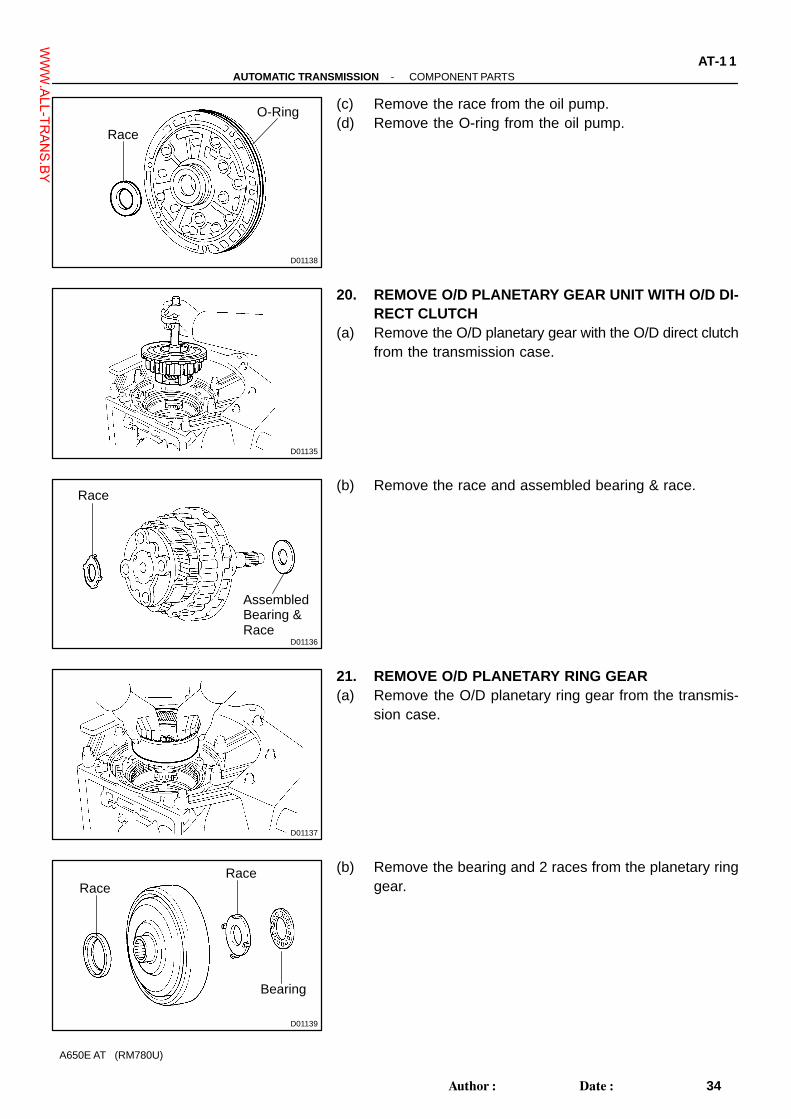
D01138
Race
O-Ring
D01135
D01136
AssembledBearing &Race
Race
D01137
D01139
RaceRace
Bearing
-AUTOMATIC TRANSMISSION COMPONENT PARTSAT-1 1
34Author�: Date�:
A650E AT (RM780U)
(c) Remove the race from the oil pump.(d) Remove the O-ring from the oil pump.
20. REMOVE O/D PLANETARY GEAR UNIT WITH O/D DI-RECT CLUTCH
(a) Remove the O/D planetary gear with the O/D direct clutchfrom the transmission case.
(b) Remove the race and assembled bearing & race.
21. REMOVE O/D PLANETARY RING GEAR(a) Remove the O/D planetary ring gear from the transmis-
sion case.
(b) Remove the bearing and 2 races from the planetary ringgear.
WWW.ALL-TR
ANS.BY

D01147
SST
D01141
D01140
D09420
D01144
AT-12-AUTOMATIC TRANSMISSION COMPONENT PARTS
35Author�: Date�:
A650E AT (RM780U)
22. CHECK PISTON STROKE OF O/D BRAKE(a) Place SST and dial indicator onto the O/D brake piston.
SST 09350-30020 (09350-06120)
(b) Measure the stroke while applying and releasing com-pressed air (392 kPa, 4 kgf/cm2, 57 psi).Piston stroke: 1.32 - 1.62 mm (0.052 - 0.064 in.)
If the stroke is non-standard, inspect the discs.
23. REMOVE FLANGE, PLATE AND DISC OF O/D BRAKE(a) Using a screwdriver, remove the snap ring.
(b) Remove the O/D brake pack as a set.HINT:Flange, 3 plates and 3 discs(c) Remove the spring from the case.
24. REMOVE O/D SUPPORT ASSEMBLY(a) Remove the 2 bolts holding the O/D support assembly
from the case.
WWW.ALL-TR
ANS.BY

D01145
SST
D01146
SST
D01431
AssembledBearing &Race
Thrust Washer
D01148
Mark
D01149
SST
-AUTOMATIC TRANSMISSION COMPONENT PARTSAT-13
36Author�: Date�:
A650E AT (RM780U)
(b) Using SST, remove the snap ring.SST 09350-30020 (09350-07060)
(c) Using SST, remove the O/D support assembly.SST 09350-30020 (09350-07020)
(d) Remove the assembled bearing & race and thrust washerfrom the O/D support.
25. CHECK PISTON ROD STROKE OF 3RD COASTBRAKE
(a) Using a water proof pen, place a mark in the 3rd coastbrake piston rod, as shown in the illustration.
(b) Using SST, measure the stroke while applying com-pressed air (392 kPa, 4 kgf/cm2, 57 psi).SST 09240-00020Piston rod stroke: 2.0 - 3.0 mm (0.079 - 0.118 in.)
If the stroke is non-standard, inspect the brake band.
WWW.ALL-TR
ANS.BY

D01150
SST
D01440
O-Ring
D01153
D01154
Forward Clutch
Direct Clutch
AT-14-AUTOMATIC TRANSMISSION COMPONENT PARTS
37Author�: Date�:
A650E AT (RM780U)
26. REMOVE 3RD COAST BRAKE COVER, PISTON AS-SEMBLY AND SPRING
(a) Using SST, remove the snap ring.SST 09350-30020 (09350-07060)
(b) Applying compressed air to the oil hole, remove the 3rdcoast brake cover, piston and spring.
(c) Remove the 2 O-rings from the cover.
27. REMOVE DIRECT CLUTCH WITH FORWARD CLUTCH(a) Remove the direct clutch with forward clutch from the
case.
(b) Remove the direct clutch from the forward clutch.
WWW.ALL-TR
ANS.BY

D01482
RaceThrust Washer
Assembled Bearing& Race
D01156
D01157
D01158
D09422
AssembledBearing& Race
Race
Bearing
-AUTOMATIC TRANSMISSION COMPONENT PARTSAT-15
38Author�: Date�:
A650E AT (RM780U)
(c) Remove the assembled bearing & race, thrust washerand race from the forward clutch.
28. REMOVE 3RD COAST BRAKE BAND(a) Using a screwdriver, remove the E-ring from the pin.HINT:Apply the grease to the E-ring and pin before the work so thatthe ring does not fly out.(b) Remove the pin from the brake band.(c) Remove the E-ring from the pin.
(d) Remove the 3rd coast brake band from the case.
29. REMOVE FORWARD CLUTCH HUB AND SUN GEARINPUT DRUM
(a) Remove the forward clutch hub and the sun gear inputdrum.
(b) Remove the assembled bearing & race, 2 races, bearingand sun gear input drum, from forward clutch hub.
WWW.ALL-TR
ANS.BY

D01168
D01160SST
D01492
D01208
ThrustWasher
D01491
AT-16-AUTOMATIC TRANSMISSION COMPONENT PARTS
39Author�: Date�:
A650E AT (RM780U)
30. REMOVE 2 BRAKE DRUM GASKETS
31. REMOVE NO. 1 ONE-WAY CLUTCH MULTIPLE DISCBRAKE AND FRONT PLANETARY GEAR
(a) Using SST, remove the snap ring.SST 09350-30020 (09350-07060)
(b) Remove the No. 1 one-way clutch from the case.
(c) Remove the thrust washer from the No. 1 one-way clutch.
(d) Remove the multiple disc brake from the case.
WWW.ALL-TR
ANS.BY

D01554
D01556
Trust Washer
D01555
D09453
D01255
-AUTOMATIC TRANSMISSION COMPONENT PARTSAT-17
40Author�: Date�:
A650E AT (RM780U)
(e) Remove the 2 washers and front planetary gear from thecase.
(f) Remove the thrust washer from the front planetary gear.
(g) Remove the front & center planetary sun gear from thecase.
32. REMOVE OUTPUT SHAFT WITH CENTER & REARPLANETARY GEAR
(a) Remove the 2nd brake pack (flange, 5 discs and 4 plates)from the case.
(b) Remove the spring from the case.
(c) Remove the output shaft with center & rear planetary gearfrom the case.
WWW.ALL-TR
ANS.BY
D01164
Thrust Washer
D01165
SST
D01166
D01167
Race
Bearing
D01481
AT-18-AUTOMATIC TRANSMISSION COMPONENT PARTS
41Author�: Date�:
A650E AT (RM780U)
(d) Remove the thrust washer from the output shaft with cen-ter & rear planetary gear.
33. REMOVE REAR PLANETARY RING GEAR(a) Using SST, remove the snap ring.
SST 09350-30020 (09350-07070)
(b) Remove the rear planetary ring gear from the case.
(c) Remove the assembled bearing & race and 2 races fromthe rear planetary ring gear.
(d) Remove the assembled bearing & race from the case.
WWW.ALL-TR
ANS.BY
AT04C-02
D01281
Torque ConverterClutch
D01282
D01283
D01284
D01285
-AUTOMATIC TRANSMISSION OIL PUMPAT-41
64Author�: Date�:
A650E AT (RM780U)
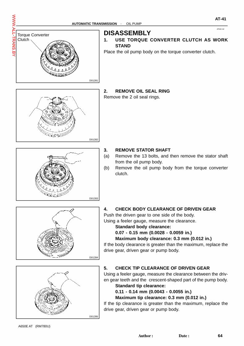
DISASSEMBLY1. USE TORQUE CONVERTER CLUTCH AS WORK
STANDPlace the oil pump body on the torque converter clutch.
2. REMOVE OIL SEAL RINGRemove the 2 oil seal rings.
3. REMOVE STATOR SHAFT(a) Remove the 13 bolts, and then remove the stator shaft
from the oil pump body.(b) Remove the oil pump body from the torque converter
clutch.
4. CHECK BODY CLEARANCE OF DRIVEN GEARPush the driven gear to one side of the body.Using a feeler gauge, measure the clearance.
Standard body clearance:0.07 - 0.15 mm (0.0028 - 0.0059 in.)Maximum body clearance: 0.3 mm (0.012 in.)
If the body clearance is greater than the maximum, replace thedrive gear, driven gear or pump body.
5. CHECK TIP CLEARANCE OF DRIVEN GEARUsing a feeler gauge, measure the clearance between the driv-en gear teeth and the crescent-shaped part of the pump body.
Standard tip clearance:0.11 - 0.14 mm (0.0043 - 0.0055 in.)Maximum tip clearance: 0.3 mm (0.012 in.)
If the tip clearance is greater than the maximum, replace thedrive gear, driven gear or pump body.
WWW.ALL-TR
ANS.BY

D01286
D01287
Driven Gear
Drive Gear
D09432
SST
AT-42-AUTOMATIC TRANSMISSION OIL PUMP
65Author�: Date�:
A650E AT (RM780U)
6. CHECK SIDE CLEARANCE OF BOTH GEARSUsing a steel straight edge and feeler gauge, measure the sideclearance of both gears.
Standard side clearance:0.02 - 0.04 mm (0.0008 - 0.0016 in.)Maximum side clearance: 0.1 mm (0.004 in.)
If the side clearance is greater than the maximum, replace thedrive gear, driven gear or pump body.
7. REMOVE OIL PUMP DRIVE GEAR AND DRIVEN GEAR
8. REMOVE OIL SEALUsing SST, remove the oil seal.
SST 09308-10010, 09950-60010 (09951-00300)
WWW.ALL-TR
ANS.BY
AT04K-02
D01303
Free
Turn
Lock
Hold
D01304
O/D Direct Clutch Assembly
D01305
TorqueConverterClutch
Oil Pump
D01489
SST
AT-56-AUTOMATIC TRANSMISSION OVERDRIVE DIRECT CLUTCH
79Author�: Date�:
A650E AT (RM780U)
DISASSEMBLY1. CHECK OPERATION OF ONE-WAY CLUTCHHold the O/D direct clutch drum and turn the input shaft.The input shaft turns freely clockwise and locks counterclock-wise.
2. REMOVE O/D DIRECT CLUTCH ASSEMBLY FROMO/D PLANETARY GEAR
3. CHECK PISTON STROKE OF O/D DIRECT CLUTCH(a) Place the oil pump onto the torque converter clutch, and
then place the O/D direct clutch assembly onto the oilpump.
(b) Using SST and a dial indicator, measure the O/D directclutch piston stroke while applying and releasing com-pressed air (392 kPa, 4 kgf/cm2, 57 psi).SST 09350-30020 (09350-06120)Piston stroke: 0.85 - 1.10 mm (0.033 - 0.043 in.)
If the stroke is non-standard, inspect the discs.
WWW.ALL-TR
ANS.BY

D01307
D01308
D09439
SST
SST
D01310
PistonReturnSpring
-AUTOMATIC TRANSMISSION OVERDRIVE DIRECT CLUTCHAT-57
80Author�: Date�:
A650E AT (RM780U)
4. REMOVE FLANGE, PLATE AND DISC(a) Using a screwdriver, remove the snap ring from the O/D
direct clutch drum.
(b) Remove the flange, 2 plates and 2 discs.
5. REMOVE PISTON RETURN SPRING(a) Place SST on the spring retainer and compress the return
spring with a press.SST 09387-00020
(b) Using SST, remove the snap ring.SST 09350-30020 (09350-07070)
(c) Remove the piston return spring.
WWW.ALL-TR
ANS.BY

D01311
D01312
D01313
D01314
One-wayClutch
Thrust Washer
Retaining Plate
AT-58-AUTOMATIC TRANSMISSION OVERDRIVE DIRECT CLUTCH
81Author�: Date�:
A650E AT (RM780U)
6. REMOVE O/D DIRECT CLUTCH PISTON(a) Place the oil pump onto the torque converter clutch and
then place the O/D direct clutch onto the oil pump.(b) Hold the O/D direct clutch piston with hand, and apply
compressed air (392 kPa, 4 kgf/cm2, 5 psi) to the oil pumpto remove the O/D direct clutch piston.
(c) Remove the O/D direct clutch piston.HINT:If the piston is at an angle and cannot be removed, press downon the side jutting out and again apply compressed air, or elsewind vinyl tape around the piston end and remove it with needlenose pliers.(d) Remove the 2 O-rings from the piston.
7. REMOVE RING GEAR FLANGE(a) Using a screwdriver, remove the snap ring.(b) Remove the ring gear flange.
8. REMOVE RETAINING PLATE(a) Using a screwdriver, remove the snap ring.
(b) Remove the retaining plate, one-way clutch and thrustwasher.
WWW.ALL-TR
ANS.BY

D01315
One-wayClutch
InnerRace
Outer Race
InnerRace
-AUTOMATIC TRANSMISSION OVERDRIVE DIRECT CLUTCHAT-59
82Author�: Date�:
A650E AT (RM780U)
9. REMOVE ONE-WAY CLUTCH FROM OUTER RACERemove the 2 inner races and one-way clutch to the outer race.
WWW.ALL-TR
ANS.BY

AT04S-02
D01344
D01345
SST
D01346
D09442
D09443
SST
SST
-AUTOMATIC TRANSMISSION DIRECT CLUTCHAT-67
90Author�: Date�:
A650E AT (RM780U)
DISASSEMBLY1. CHECK PISTON STROKE OF DIRECT CLUTCH(a) Place the direct clutch assembly onto the O/D support as-
sembly.
(b) Using SST and a dial indicator, measure the direct clutchpiston stroke while applying and releasing compressedair (186 - 206 kPa, 1.9 - 2.1 kgf/cm2, 27 - 30 psi).SST 09350-30020 (09350-06120)Piston stroke: 0.40 - 0.70 mm (0.016 - 0.028 in.)
If the clearance is non-standard inspect the discs.
2. REMOVE FLANGE, PLATE AND DISC(a) Using a screwdriver, remove the snap ring from the direct
clutch drum.
(b) Remove the flange, 4 plates and 4 discs.(c) Remove the cushion plate.
3. REMOVE PISTON RETURN SPRING(a) Place SST on the piston return spring and compress.
SST 09387-00020(b) Using SST, remove the snap ring.
SST 09350-30020 (09350-07070)
WWW.ALL-TR
ANS.BY

D01349
PistonReturnSpring
D01350
D01351
O-Ring
AT-68-AUTOMATIC TRANSMISSION DIRECT CLUTCH
91Author�: Date�:
A650E AT (RM780U)
(c) Remove the piston return spring.
4. REMOVE DIRECT CLUTCH PISTON(a) Place the direct clutch drum onto the O/D support.(b) Hold the direct clutch piston and apply compressed air
(186 kPa, 1.9 kgf/cm2, 27 psi) to the O/D support to re-move the direct clutch piston.
HINT:Make sure the direct clutch piston squares in the drum beforeapplying compressed air(c) Remove the direct clutch piston.
(d) Using a small screwdriver, remove the 2 O-rings from thepiston.
WWW.ALL-TR
ANS.BY

AT04W-02
D01356
D01357
SST
D01358
D01274
SST
SST
D01359
PistonReturnSpring
-AUTOMATIC TRANSMISSION FORWARD CLUTCHAT-73
96Author�: Date�:
A650E AT (RM780U)
DISASSEMBLY1. PLACE FORWARD CLUTCH INTO O/D SUPPORT(a) Place wooden blocks, etc, to prevent forward clutch shaft
from touching the work stand, and place the O/D supporton them.
(b) Place the forward clutch into the O/D support.
2. CHECK PISTON STROKE OF FORWARD CLUTCHUsing SST and a dial indicator, measure forward clutch pistonstroke while applying and releasing compressed air (186 kPa,1.9 kgf/cm2, 27 psi).
SST 09350-30020 (09350-06120)Piston stroke: 0.60 - 0.90 mm (0.024 - 0.035 in.)
If the clearance is non-standard, inspect the discs.
3. REMOVE FLANGE, PLATE AND DISC(a) Using a screwdriver, remove the snap ring from the for-
ward clutch drum.(b) Remove the flange, 5 plates and 5 discs.(c) Remove the cushion plate.
4. REMOVE PISTON RETURN SPRING(a) Place SST on the spring retainer and compress the return
spring with a press.SST 09350-30020 (09350-07040)
(b) Using SST, remove the snap ring.SST 09350-30020 (09350-07070)
(c) Remove the piston return spring.
WWW.ALL-TR
ANS.BY

D01360
D01361
O-Ring
D01362
AT-74-AUTOMATIC TRANSMISSION FORWARD CLUTCH
97Author�: Date�:
A650E AT (RM780U)
5. REMOVE FORWARD CLUTCH PISTON(a) Place the forward clutch drum onto the O/D support.(b) Hold the forward clutch piston with hand, apply com-
pressed air (186 kPa, 1.9 kgf/cm2, 27 psi) to the O/D sup-port to remove the forward clutch piston.
(c) Remove the forward clutch piston.
6. REMOVE 2 O-RINGS FROM PISTONUsing a small screwdriver, remove the 2 O-rings.
7. REMOVE 3 OIL SEAL RINGS FROM FORWARDCLUTCH
WWW.ALL-TR
ANS.BY

AT050-02
D01209
SST
D01210
D09448
D01212
SSTSST
-AUTOMATIC TRANSMISSION MULTIPLE DISC BRAKEAT-79
102Author�: Date�:
A650E AT (RM780U)
DISASSEMBLY1. CHECK PISTON STROKE OF 3RD BRAKE PISTONUsing SST and a dial indicator, measure the 3rd brake pistonstroke while applying and releasing compressed air (392 kPa,4 kg/cm2, 57 psi).
SST 09350-30020 (09350-06120)If the stroke is non-standard, inspect the disc.
Piston stroke: 0.56 - 0.86 mm (0.022 - 0.036 in.)NOTICE:Do not applying compressed air into the 2nd brake hole.
2. REMOVE FLANGE, PLATE AND DISC(a) Using a screwdriver, remove the snap ring from the brake
drum.
(b) Remove the flange, 7 plates and 4 discs.
3. REMOVE PISTON RETURN SPRING(a) Place SST on the spring retainer and compress the return
spring with a press.SST 09350-32014 (09351-32040)
(b) Using SST, remove the snap ring.SST 09350-30020 (09350-07070)
WWW.ALL-TR
ANS.BY

D01224
Retainer
PistonReturnSpring
D01214
2nd BrakePiston
D01215
D01221
O-Ring
O-Ring
3rd BrakePiston
2nd BrakePiston
AT-80-AUTOMATIC TRANSMISSION MULTIPLE DISC BRAKE
103Author�: Date�:
A650E AT (RM780U)
(c) Remove the retainer and piston return spring.
4. REMOVE 3RD AND 2ND BRAKE PISTON(a) Push the 2nd brake piston down with fingers to remove.
(b) Hold the 3rd brake piston so that it dose not slant, and ap-ply compressed air (392 kPa, 4 kg/cm2, 57 psi) into thepassage to remove the 3rd brake piston.
(c) Remove the 4 O-rings from the 3rd and 2nd brake pis-tons.
WWW.ALL-TR
ANS.BY

AT054-01
D01226
D01227
Bearing
Race
Center Planetary Gear
Center PlanetaryRing Gear
D01228
D01474
Center PlanetaryRing Gear
Intermediate shaft
AT-86-AUTOMATIC TRANSMISSION CENTER PLANETARY GEAR
109Author�: Date�:
A650E AT (RM780U)
DISASSEMBLY1. REMOVE CENTER PLANETARY GEAR(a) Using a needle nose plier, nip the snap ring to remove the
front planetary ring gear.
(b) Remove the center planetary gear, bearing and 2 racesfrom center planetary ring gear.
2. REMOVE CENTER PLANETARY RING GEAR(a) Using a screwdriver, remove the snap ring.
(b) Remove the center planetary ring gear from the inter-mediate shaft.
WWW.ALL-TR
ANS.BY

AT058-01
D01439
Rear PlanetarySun Gear
D01232
D01233
Rear PlanetaryRing Gear Flange
Rear PlanetaryRing Gear
AT-90-AUTOMATIC TRANSMISSION REAR PLANETARY GEAR
113Author�: Date�:
A650E AT (RM780U)
DISASSEMBLY1. REMOVE REAR PLANETARY SUN GEAR
2. REMOVE REAR PLANETARY RING GEAR FLANGE(a) Using a screwdriver, remove the snap ring.
(b) Remove the rear planetary ring gear flange from the rearplanetary ring gear.
WWW.ALL-TR
ANS.BY

AT05C-02
D01236
D01480
D09449
D01237
SST Snap Ring
D01238
AT-94-AUTOMATIC TRANSMISSION FIRST AND REVERSE BRAKE
117Author�: Date�:
A650E AT (RM780U)
DISASSEMBLY1. CHECK PACK CLEARANCE OF 1ST & REVERSE
BRAKEMake sure the 1st & reverse brake pistons move smoothlywhen applying and releasing the compressed air (392 kPa, 4kgf/cm2, 57 psi) into the transmission case.
Pack clearance: 0.5 - 0.8 mm (0.021 - 0.031 in.)
2. REMOVE DISC, PLATE AND FLANGE(a) Using a screwdriver, remove the snap ring.
(b) Remove the flange, 5 discs and 5 plates.
3. REMOVE PISTON RETURN SPRING(a) Place SST on the spring retainer and compress the return
spring.SST 09350-30020 (09350-07050)
(b) Using SST, remove the snap ring and return spring.SST 09350-30020 (09350-07070)
4. REMOVE NO. 2 BRAKE PISTON(a) Hold No. 2 brake piston by hand, apply compressed air
(392 kPa, 4 kgf/cm2, 57 psi) to transmission case to re-move No. 2 brake piston.
HINT:If the piston dose not pop out with compressed air, lift the pistonout with needle-nose pliers.(b) Remove the O-ring from No. 2 brake piston.
WWW.ALL-TR
ANS.BY

D01239
SST
D01240
SST
-AUTOMATIC TRANSMISSION FIRST AND REVERSE BRAKEAT-95
118Author�: Date�:
A650E AT (RM780U)
5. REMOVE REACTION SLEEVE(a) Using SST, remove the reaction sleeve.
SST 09350-30020 (09350-07080)(b) Remove the O-ring from the reaction sleeve.
6. REMOVE NO. 1 BRAKE PISTON(a) Using SST, remove the No. 1 brake piston.
SST 09350-30020 (09350-07090)(b) Remove the 2 O-rings from the No. 1 piston.
WWW.ALL-TR
ANS.BY

AT0Y2-01
D09427
D09428
AT-100-AUTOMATIC TRANSMISSION EXTENSION HOUSING
123Author�: Date�:
A650E AT (RM780U)
DISASSEMBLY1. REMOVE EXTENSION HOUSING DUST DEFLECTORUsing a plastic hammer, remove the dust deflector.
2. REMOVE EXTENSION HOUSING OIL SEALUsing a screwdriver, remove the oil seal.
WWW.ALL-TR
ANS.BY

IN0D6-01
IN-6-INTRODUCTION TERMS
6Author�: Date�:
A650E AT (RM780U)
GLOSSARY OF SAE AND LEXUS TERMSThis glossary lists all SAE-J1930 terms and abbreviations used in this manual in compliance with SAE rec-ommendations, as well as their LEXUS equivalents.
SAE
ABBREVIATIONSSAE TERMS
LEXUS TERMS
( )--ABBREVIATIONS
A/C Air Conditioning Air Conditioner
ACL Air Cleaner Air Cleaner, A/CL
AIR Secondary Air Injection Air Injection (AI)
AP Accelerator Pedal -
B+ Battery Positive Voltage +B, Battery Voltage
BARO Barometric Pressure HAC
CAC Charge Air Cooler Intercooler
CARB Carburetor Carburetor
CFI Continuous Fuel Injection -
CKP Crankshaft Position Crank Angle
CL Closed Loop Closed Loop
CMP Camshaft Position Cam Angle
CPP Clutch Pedal Position -
CTOX Continuous Trap Oxidizer -
CTP Closed Throttle Position LL ON, Idle ON
DFI Direct Fuel Injection (Diesel) Direct Injection (DI)
DI Distributor Ignition -
DLC1
DLC2
DLC3
Data Link Connector 1
Data Link Connector 2
Data Link Connector 3
1: Check Connector
2: Total Diagnosis Comunication Link (TDCL)
3: OBD II Diagnostic Connector
DTC Diagnostic Trouble Code Diagnostic Code
DTM Diagnostic Test Mode -
ECL Engine Control Level -
ECM Engine Control Module Engine ECU (Electronic Control Unit)
ECT Engine Coolant Temperature Coolant Temperature, Water Temperature (THW)
EEPROM Electrically Erasable Programmable Read Only Memory
Electrically Erasable Programmable Read Only Memory
(EEPROM),
Erasable Programmable Read Only Memory (EPROM)
EFE Early Fuel Evaporation Cold Mixture Heater (CMH), Heat Control Valve (HCV)
EGR Exhaust Gas Recirculation Exhaust Gas Recirculation (EGR)
EI Electronic Ignition TOYOTA Distributorless Ignition (TDI)
EM Engine Modification Engine Modification (EM)
EPROM Erasable Programmable Read Only Memory Programmable Read Only Memory (PROM)
EVAP Evaporative Emission Evaporative Emission Control (EVAP)
FC Fan Control -
FEEPROMFlash Electrically Erasable Programmable Read Only
Memory-
FEPROM Flash Erasable Programmable Read Only Memory -
FF Flexible Fuel -
FP Fuel Pump Fuel Pump
GEN Generator Alternator
GND Ground Ground (GND)
WWW.ALL-TR
ANS.BY

-INTRODUCTION TERMSIN-7
7Author�: Date�:
A650E AT (RM780U)
HO2S Heated Oxygen Sensor Heated Oxygen Sensor (HO2S)
IAC Idle Air Control Idle Speed Control (ISC)
IAT Intake Air Temperature Intake or Inlet Air Temperature
ICM Ignition Control Module -
IFI Indirect Fuel Injection Indirect Injection (IDL)
IFS Inertia Fuel-Shutoff -
ISC Idle Speed Control -
KS Knock Sensor Knock Sensor
MAF Mass Air Flow Air Flow Meter
MAP Manifold Absolute PressureManifold Pressure
Intake Vacuum
MC Mixture Control
Electric Bleed Air Control Valve (EBCV)
Mixture Control Valve (MCV)
Electric Air Control Valve (EACV)
MDP Manifold Differential Pressure -
MFI Multiport Fuel Injection Electronic Fuel Injection (EFI)
MIL Malfunction Indicator Lamp Check Engine Lamp
MST Manifold Surface Temperature -
MVZ Manifold Vacuum Zone -
NVRAM Non-Volatile Random Access Memory -
O2S Oxygen Sensor Oxygen Sensor, O2 Sensor (O2S)
OBD On-Board Diagnostic On-Board Diagnostic System (OBD)
OC Oxidation Catalytic Converter Oxidation Catalyst Convert (OC), CCo
OP Open Loop Open Loop
PAIR Pulsed Secondary Air Injection Air Suction (AS)
PCM Powertrain Control Module -
PNP Park/Neutral Position -
PROM Programmable Read Only Memory -
PSP Power Steering Pressure -
PTOX Periodic Trap OxidizerDiesel Particulate Filter (DPF)
Diesel Particulate Trap (DPT)
RAM Random Access Memory Random Access Memory (RAM)
RM Relay Module -
ROM Read Only Memory Read Only Memory (ROM)
RPM Engine Speed Engine Speed
SC Supercharger Supercharger
SCB Supercharger Bypass E-ABV
SFI Sequential Multiport Fuel Injection Electronic Fuel Injection (EFI), Sequential Injection
SPL Smoke Puff Limiter -
SRI Service Reminder Indicator -
SRT System Readiness Test -
ST Scan Tool -
TB Throttle Body Throttle Body
TBI Throttle Body Fuel InjectionSingle Point Injection
Central Fuel Injection (Ci)
TC Turbocharger Turbocharger
TCC Torque Converter Clutch Torque Converter
WWW.ALL-TR
ANS.BY
IN-8-INTRODUCTION TERMS
8Author�: Date�:
A650E AT (RM780U)
TCM Transmission Control Module Transmission ECU, ECT ECU
TP Throttle Position Throttle Position
TR Transmission Range -
TVV Thermal Vacuum ValveBimetallic Vacuum Switching Valve (BVSV)
Thermostatic Vacuum Switching Valve (TVSV)
TWC Three-Way Catalytic Converter
Three-Way Catalytic (TWC)
Manifold Converter
CCRO
TWC+OC Three-Way + Oxidation Catalytic Converter CCR + CCo
VAF Volume Air Flow Air Flow Meter
VR Voltage Regulator Voltage Regulator
VSS Vehicle Speed Sensor Vehicle Speed Sensor
WOT Wide Open Throttle Full Throttle
WU-OC Warm Up Oxidation Catalytic Converter -
WU-TWC Warm Up Three-Way Catalytic Converter -
3GR Third Gear -
4GR Fourth Gear -
WWW.ALL-TR
ANS.BY

SS0ZU-01
6N
8N
10N
11N
12N
B06432
Nut Type
Present Standard Hexagon Nut Cold Forging Nut Cutting Processed Nut
Class
4N
5N (4T)
6N
7N (5T)
8N
10N (7T)
11N
12N
Old Standard Hexagon Nut
No Mark (w/ Washer)
No Mark
*
No Mark (w/ Washer) No Mark
No Mark
*: Nut with 1 or more marks on one side surface of the nut.
-SERVICE SPECIFICATIONS STANDARD BOLTSS-3
17Author�: Date�:
A650E AT (RM780U)
HOW TO DETERMINE NUT STRENGTH
HINT:Use the nut with the same number of the nut strength classification or the greater than the bolt strength clas-sification number when tightening parts with a bolt and nut.Example: Bolt = 4T Nut = 4N or more
WWW.ALL-TR
ANS.BY

SS0ZS-01
4
5
6
7
8
9
10
11
B06431
Bolt Type
Hexagon Head Bolt
Normal Recess Bolt Deep Recess BoltStud Bolt Weld Bolt
Class
4T
5T
6T
7T
8T
9T
10T
11T
No Mark
w/ Washer
No Mark No Mark
w/ Washer
-SERVICE SPECIFICATIONS STANDARD BOLTSS-1
15Author�: Date�:
A650E AT (RM780U)
STANDARD BOLTHOW TO DETERMINE BOLT STRENGTH
WWW.ALL-TR
ANS.BY
IN047-15
D01280
Oil Pump Body
Oil Pump Drive Gear
Stator Shaft
Oil Seal Ring
Oil Pump Driven Gear
�
� Oil Seal
N·m (kgf·cm, ft·lbf)� Non-reusable part
: Specified torque
X13
10 (100, 7)
O-ring
-INTRODUCTION HOW TO USE THIS MANUALIN-1
1Author�: Date�:
A650E AT (RM780U)
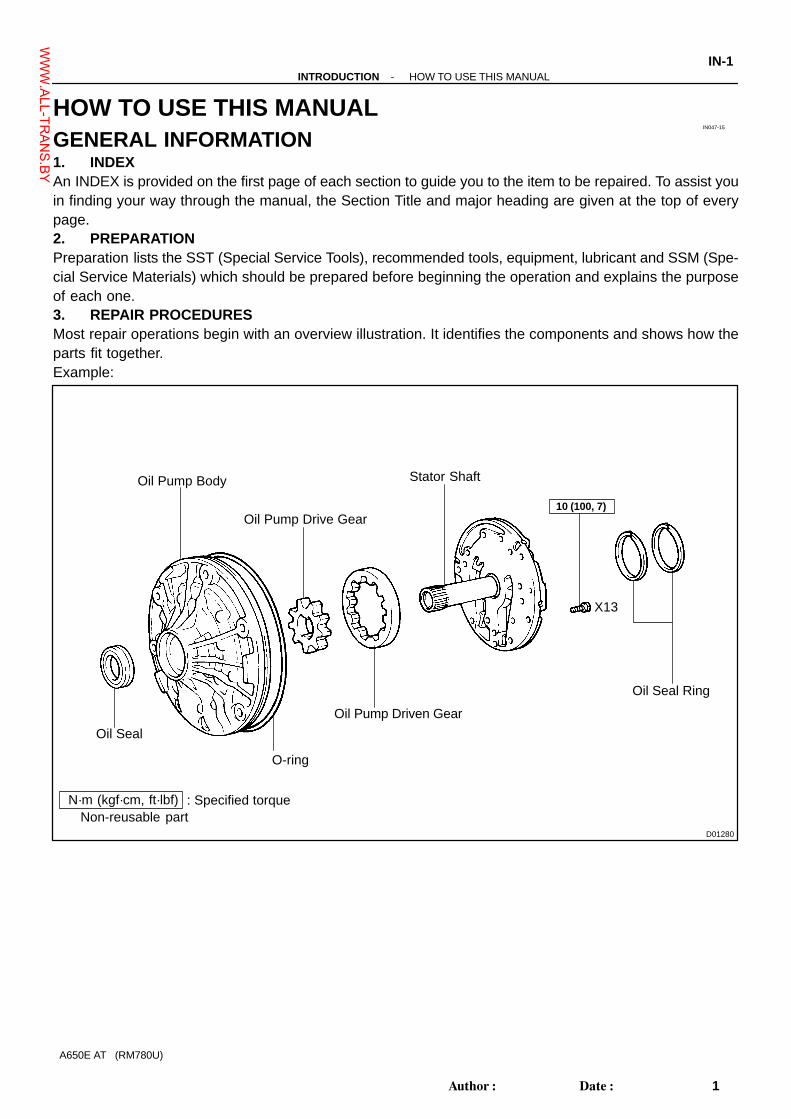
HOW TO USE THIS MANUALGENERAL INFORMATION1. INDEXAn INDEX is provided on the first page of each section to guide you to the item to be repaired. To assist youin finding your way through the manual, the Section Title and major heading are given at the top of everypage.2. PREPARATIONPreparation lists the SST (Special Service Tools), recommended tools, equipment, lubricant and SSM (Spe-cial Service Materials) which should be prepared before beginning the operation and explains the purposeof each one.3. REPAIR PROCEDURESMost repair operations begin with an overview illustration. It identifies the components and shows how theparts fit together.Example:
WWW.ALL-TR
ANS.BY

Illustration:what to do and where
21. CHECK PISTON STROKE OF OVERDRIVE BRAKE
(a) Place SST and a dial indicator onto the overdrive brakepiston as shown in the illustration.
Task heading : what to do
SST 09350-30020 (09350-06120)
Set part No. Component part No.Detailed text : how to do task
(b) Measure the stroke applying and releasing the compressed
Piston stroke: 1.40 � 1.70 mm (0.0551 � 0.0669 in.)
Specification
air (392 - 785 kPa, 4 - 8 kgf.cm2 or 57 - 114 psi) asshown in the illustration.
IN-2-INTRODUCTION HOW TO USE THIS MANUAL
2Author�: Date�:
A650E AT (RM780U)
The procedures are presented in a step-by-step format:� The illustration shows what to do and where to do it.� The task heading tells what to do.� The detailed text tells how to perform the task and gives other information such as specifications
and warnings.Example:
This format provides the experienced technician with a FAST TRACK to the information needed. The uppercase task heading can be read at a glance when necessary, and the text below it provides detailed informa-tion. Important specifications and warnings always stand out in bold type.4. REFERENCESReferences have been kept to a minimum. However, when they are required you are given the page to referto.5. SPECIFICATIONSSpecifications are presented in bold type throughout the text where needed. You never have to leave theprocedure to look up your specifications. They are also found at the end of each section, for quick reference.6. CAUTIONS, NOTICES, HINTS:� CAUTIONS are presented in bold type, and indicate there is a possibility of injury to you or other
people.� NOTICES are also presented in bold type, and indicate the possibility of damage to the components
being repaired.� HINTS are separated from the text but do not appear in bold. They provide additional information to
help you perform the repair efficiently.7. SI UNITThe UNITS given in this manual are primarily expressed according to the SI UNIT (International System ofUnit), and alternately expressed in the metric system and in the English System.Example:
Torque: 30 N·m (310 kgf·cm, 22 ft·lbf)
WWW.ALL-TR
ANS.BY

AT04H-02
D01300
PrintedNumber
-AUTOMATIC TRANSMISSION THIRD COAST BRAKEAT-47
70Author�: Date�:
A650E AT (RM780U)
INSPECTIONINSPECT BRAKE BANDIf the lining of the brake band is peeling off or discolored, or evenif a part of the printed numbers are defaced, replace the brakeband.HINT:Before assembling the new band, soak it in ATF for at least 15minutes.
WWW.ALL-TR
ANS.BY

AT04P-02
D01216
D01246
AT-52-AUTOMATIC TRANSMISSION OVERDRIVE BRAKE
75Author�: Date�:
A650E AT (RM780U)
INSPECTION1. INSPECT DISC, PLATE AND FLANGECheck to see if the sliding surface of the disc, plate and flangeare worn or burnt. If necessary, replace them.HINT:� If the lining of the disc is peeling off or discolored, or even
if a part of the printed numbers is defaced, replace alldiscs.
� Before assembling new discs, soak them in ATF for atleast 15 minutes.
2. CHECK O/D BRAKE PISTON RETURN SPRINGMeasure the free length of the spring together with the springseat.
Standard free length: 17.82 mm (0.702 in.)
WWW.ALL-TR
ANS.BY

AT04D-02
D01290
D01291
-AUTOMATIC TRANSMISSION OIL PUMPAT-43
66Author�: Date�:
A650E AT (RM780U)
INSPECTION1. CHECK OIL PUMP BODY BUSHINGUsing a caliper gauge, measure the inside diameter of the oilpump body bushing.
Maximum inside diameter: 38.19 mm (1.5035 in.)If the inside diameter is greater than the maximum, replace theoil pump body.
2. CHECK STATOR SHAFT BUSHINGUsing a caliper gauge, measure the inside diameter of the sta-tor shaft bushing.
Maximum inside diameter:Front side: 21.58 mm (0.8496 in.)Rear side: 27.08 mm (1.0661 in.)
If the inside diameter is grater than the maximum, replace thestator shaft.
WWW.ALL-TR
ANS.BY

AT04L-01
D01216
D01316
D01246
D01317
AT-60-AUTOMATIC TRANSMISSION OVERDRIVE DIRECT CLUTCH
83Author�: Date�:
A650E AT (RM780U)
INSPECTION1. INSPECT DISC AND FLANGECheck to see if the sliding surface of the disc, plate and flangeare worn or burnt. If necessary, replace them.HINT:� If the lining of the disc is peeling off or discolored, or even
if a part of the printed numbers is defaced, replace alldiscs.
� Before assembling new discs, soak them in ATF for atleast 15 minutes.
2. CHECK O/D DIRECT CLUTCH PISTON(a) Check that the check ball is free by shaking the piston.(b) Check that the valve does not leak by applying low-pres-
sure compressed air.
3. CHECK O/D DIRECT CLUTCH RETURN SPRINGMeasure the free length of the spring together with the springseat.
Standard free length: 15.8 mm (0.622 in.)
4. CHECK O/D DIRECT CLUTCH DRUM BUSHINGSUsing a dial indicator, measure the inside diameter of the clutchdrum bushings.
Maximum inside diameter: 27.11 mm (1.0673 in.)If the inside diameter is greater than the maximum, replace theclutch drum.
WWW.ALL-TR
ANS.BY

D01318
D01319
-AUTOMATIC TRANSMISSION OVERDRIVE DIRECT CLUTCHAT-61
84Author�: Date�:
A650E AT (RM780U)
5. CHECK O/D PLANETARY GEAR BUSHINGUsing a dial indicator, measure the inside diameter of the plane-tary gear bushing.
Maximum inside diameter: 11.27 mm (0.444 in.)If the inside diameter is greater than the maximum, replace theplanetary gear.
6. MEASURE PLANETARY PINION GEAR THRUSTCLEARANCE
Using a feeler gauge, measure the planetary pinion gear thrustclearance.
Standard clearance: 0.2 - 0.6 mm (0.008 - 0.024 in.)Maximum clearance: 1.0 mm (0.039 in.)
If the clearance is greater than the maximum, replace the plane-tary gear assembly.
WWW.ALL-TR
ANS.BY

AT04T-01
D01246
D01424
D01216
D01352
-AUTOMATIC TRANSMISSION DIRECT CLUTCHAT-69
92Author�: Date�:
A650E AT (RM780U)
INSPECTION1. CHECK DIRECT CLUTCH PISTON RETURN SPRINGMeasure the free length of the spring together with the springseat.
Standard free length: 23.25 mm (0.915 in.)
2. CHECK DIRECT CLUTCH PISTON(a) Check that the check ball is free by shaking the piston.(b) Check that the valve does not leak by applying low-pres-
sure compressed air.
3. INSPECT DISC, PLATE AND FLANGECheck to see if the sliding surface of the disc, plate and flangeare worn or burnt. If necessary, replace them.HINT:� If the lining of the disc is peeling off or discolored, or even
if a part of the printed numbers is defaced, replace alldiscs.
� Before assembling new discs, soak them in ATF for atleast 15 minutes.
4. CHECK DIRECT CLUTCH BUSHINGUsing a deal indicator, measure the inside diameter of theclutch drum bushing.
Maximum inside diameter: 53.97 mm (2.1248 in.)If the inside diameter is greater than the maximum, replace theclutch drum.
WWW.ALL-TR
ANS.BY

AT04X-01
D01216
D01424
D01363
-AUTOMATIC TRANSMISSION FORWARD CLUTCHAT-75
98Author�: Date�:
A650E AT (RM780U)
INSPECTION1. INSPECT DISC, PLATE AND FLANGECheck to see if the sliding surface of the disc, plate and flangeare worn or burnt. If necessary, replace them.HINT:� If the lining of the disc is peeling off or discolored, or even
if a part of th printed numbers is defaced, replace all discs.� Before assembling new discs, soak them in ATF for at
least 15 minutes.
2. CHECK FORWARD CLUTCH PISTON(a) Check that the check ball is free by shaking the piston.(b) Check that the valve does not leak by applying low-pres-
sure compressed air.
3. CHECK FORWARD CLUTCH DRUM BUSHINGUsing a dial indicator, measure the inside diameter of the for-ward clutch drum bushing.
Maximum inside diameter: 20.08 mm (0.790 in.)If the inside diameter is greater than the maximum, replace theforward clutch drum.
WWW.ALL-TR
ANS.BY

AT051-01
D01241
D01575
D01218Free
Turn
Lock
Hold
D01219
-AUTOMATIC TRANSMISSION MULTIPLE DISC BRAKEAT-81
104Author�: Date�:
A650E AT (RM780U)
INSPECTION1. INSPECT DISC AND FLANGECheck to see if the sliding surface of the disc, plate and flangeare worn or burnt. If necessary, replace them.HINT:� If the lining of the disc is peeling off or discorded, or even
if a part of the printed numbers is defaced, replace alldiscs.
� Before assembling new discs, soak them in ATF for atleast 15 minutes.
2. CHECK PISTON RETURN SPRINGMeasure the free length of the spring together with the springseat.
Standard free length: 36.8 mm (1.449 in.)
3. CHECK OPERATION OF ONE-WAY CLUTCHHold the front & center planetary sun gear and turn the hub. Thehub must be able to turn freely clockwise and locks counter-clockwise.
4. MEASURE PLANETARY PINION GEAR THRUSTCLEARANCE
Using a feeler gauge, measure the planetary pinion gear thrustclearance.
Standard clearance: 0.2 - 0.6 mm (0.008 - 0.024 in.)Maximum clearance: 1.0 mm (0.039 in.)
If the clearance is greater than the maximum, replace the plane-tary gear assembly.
WWW.ALL-TR
ANS.BY

D01220
AT-82-AUTOMATIC TRANSMISSION MULTIPLE DISC BRAKE
105Author�: Date�:
A650E AT (RM780U)
5. CHECK FRONT & CENTER PLANETARY SUN GEARBUSHING
Using a dial indicator, measure the inside diameter of the plane-tary sun gear bushing.
Maximum inside diameter: 24.79 mm (0.976 in.)If the inside diameter is greater then the maximum, replace theplanetary sun gear.
WWW.ALL-TR
ANS.BY

AT055-01
D01230
D01231
-AUTOMATIC TRANSMISSION CENTER PLANETARY GEARAT-87
110Author�: Date�:
A650E AT (RM780U)
INSPECTION1. CHECK CENTER PLANETARY GEAR BUSHINGUsing a dial indicator, measure the inside diameter of the plane-tary gear bushing
Maximum inside diameter: 41.31 mm (1.626 in.)If the inside diameter is greater than the maximum, replace theplanetary gear.
2. MEASURE PLANETARY PINION GEAR THRUSTCLEARANCE
Using a feeler gauge, measure the planetary pinion gear thrustclearance.
Standard clearance: 0.2 - 0.6 mm (0.008 - 0.024 in.)Maximum clearance: 1.0 mm (0.039 in.)
If the clearance is greater than the maximum, replace the plane-tary gear assembly.
WWW.ALL-TR
ANS.BY

AT059-02
D01234
D01558
D01559
D01235
Hold
Lock Free
Turn
-AUTOMATIC TRANSMISSION REAR PLANETARY GEARAT-91
114Author�: Date�:
A650E AT (RM780U)
INSPECTION1. MEASURE PLANETARY PINION GEAR THRUST
CLEARANCEUsing a feeler gauge, measure the planetary pinion gear thrustclearance.
Standard clearance: 0.2 - 0.6 mm (0.008 - 0.024 in.)Maximum clearance: 1.0 mm (0.039 in.)
If the clearance is greater than the maximum, replace the plane-tary gear assembly.
2. CHECK REAR PLANETARY RING GEAR BUSHINGUsing a dial indicator, measure the inside diameter of the rearplanetary ring gear bushing.
Maximum inside diameter: 38.56 mm (1.518 in.)If the inside diameter is greater than the maximum, replace therear planetary ring gear.
3. CHECK OUTPUT SHAFT BUSHINGUsing a dial indicator, measure the inside diameter of the outputshaft bushing.
Maximum inside diameter: 20.08 mm (0.791 in.)If the inside diameter is greater than the maximum, replace theoutput shaft.
4. CHECK OPERATION ONE-WAY CLUTCH(a) Install the No. 2 one-way clutch to rear planetary ring
gear.(b) Hold the rear planetary ring gear and turn the one-way
clutch.(c) The one-way clutch turns freely clockwise and locks
counterclockwise.(d) Remove the No. 2 one-way clutch from rear planetary
ring gear.
WWW.ALL-TR
ANS.BY
AT05D-01
D01241
D01576
AT-96-AUTOMATIC TRANSMISSION FIRST AND REVERSE BRAKE
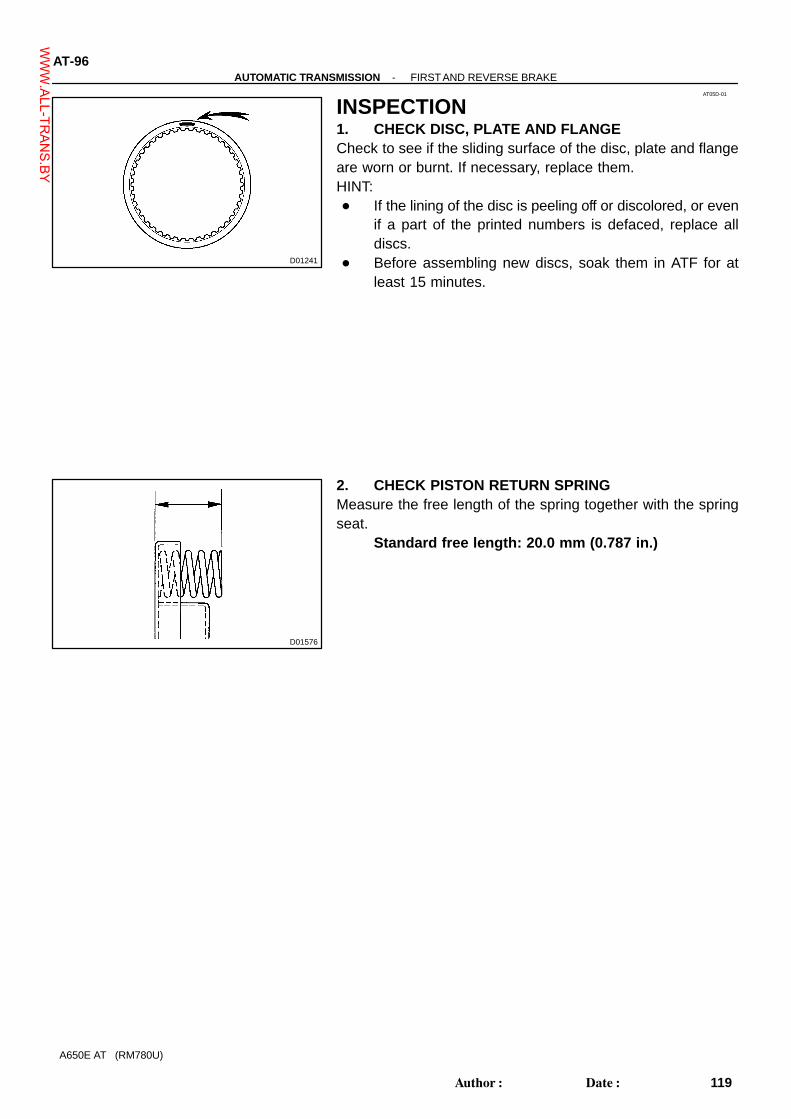
119Author�: Date�:
A650E AT (RM780U)
INSPECTION1. CHECK DISC, PLATE AND FLANGECheck to see if the sliding surface of the disc, plate and flangeare worn or burnt. If necessary, replace them.HINT:� If the lining of the disc is peeling off or discolored, or even
if a part of the printed numbers is defaced, replace alldiscs.
� Before assembling new discs, soak them in ATF for atleast 15 minutes.
2. CHECK PISTON RETURN SPRINGMeasure the free length of the spring together with the springseat.
Standard free length: 20.0 mm (0.787 in.)
WWW.ALL-TR
ANS.BY

AT0J9-04
D09429
-AUTOMATIC TRANSMISSION EXTENSION HOUSINGAT-101
124Author�: Date�:
A650E AT (RM780U)
INSPECTIONINSPECT EXTENSION HOUSING BUSHINGUsing a calipers gauge, measure the inside diameter of the ex-tension housing bushing.
Maximum inside diameter: 40.08 mm (1.5779 in.)If the inside diameter is greater than the maximum, replace theextension housing.
WWW.ALL-TR
ANS.BY

AT0Y4-01
D01170
A
B
C D
EF
G H I J
K
L
AT-1 10-AUTOMATIC TRANSMISSION UPPER VALVE BODY
133Author�: Date�:
A650E AT (RM780U)
UPPER VALVE BODYLOCATION1. SPRINGHINT:During reassembly, please refer to the spring specifications below to help you differentiate among the differ-ent springs.
Mark Name (Color)Free length / Outer diameter
mm (in.)Total No. of coils
A Lock-up Relay Valve (Red) 23.42 (0.922) / 5.86 (0.231) 12.25
B C-0 Exhaust Valve (Orange) 24.25 (0.955) / 8.70 (0.343) 7.58
C 4-5 Shift Valve (Red) 25.50 (1.004) / 9.73 (0.383) 7.75
D Coast Brake Control Valve (Green) 26.92 (1.060) / 8.70 (0.343) 10.53
E Secondary Regulator Valve (Red) 34.48 (1.357) / 9.22 (0.363) 13.5
F C-1 Orifice Control Valve (White) 37.13 (1.461) / 11.14 (0.439) 11.25
G C-1 Orifice Control Valve (None) 21.50 (0.846) / 7.76 (0.306) 11.5
H C-1 Accumulator Valve (Yellow) 78.16 (3.077) / 17.50 (0.689) 15.9
I Solenoid Modulator Valve (Light blue) 35.99 (1.417) / 8.30 (0.327) 13.8
J 2-3 Shift Valve (Red) 25.50 (1.004) / 9.73 (0.383) 7.75
K B-3 Control Valve (Yellow) 26.05 (1.026) / 7.20 (0.283) 11.83
L B-3 Control Valve (Pink) 19.79 (0.779) / 7.70 (0.303) 8.51
WWW.ALL-TR
ANS.BY

D01173
AB
C D
E F G HI J
K
-AUTOMATIC TRANSMISSION UPPER VALVE BODYAT-1 11
134Author�: Date�:
A650E AT (RM780U)
2. RETAINER
Mark RetainerHeight / Width / Thickness
mm (in.)
A Lock-up Relay Valve - / - / -
B C-0 Exhaust Valve 8.5 (0.335) / 5.0 (0.197) / 3.2 (0.126)
C 4-5 Shift Valve 10.0 (0.394) / 5.0 (0.197) / 3.2 (0.126)
D Coast Brake Control Valve 15.0 (0.591) / ø 5.0 (ø 0.197) / ø 5.0 (ø 0.197)
E Secondary Regulator Valve 10.0 (0.394) / 5.0 (0.197) / 3.2 (0.126)
F C-1 Orifice Control Valve 8.5 (0.335) / 5.0 (0.197) / 3.2 (0.126)
G C-1 Accumulator Valve 36.5 (1.437) / - / 3.2 (0.126)
H Solenoid Modulator Valve 21.0 (0.827) / - / 3.2 (0.126)
I Check Valve 10.0 (0.394) / 5.0 (0.197) / 3.2 (0.126)
J 2-3 Shift Valve 8.0 (0.315) / 8.0 (0.315) / 3.2 (0.126)
K B-3 Control Valve 16.5 (0.650) / 6.0 (0.236) / 3.2 (0.126)
WWW.ALL-TR
ANS.BY

D09450
AT-1 12-AUTOMATIC TRANSMISSION UPPER VALVE BODY
135Author�: Date�:
A650E AT (RM780U)
3. CHECK BALL
WWW.ALL-TR
ANS.BY
AT0Y5-01
D01171
A BC D
E
F
G HI
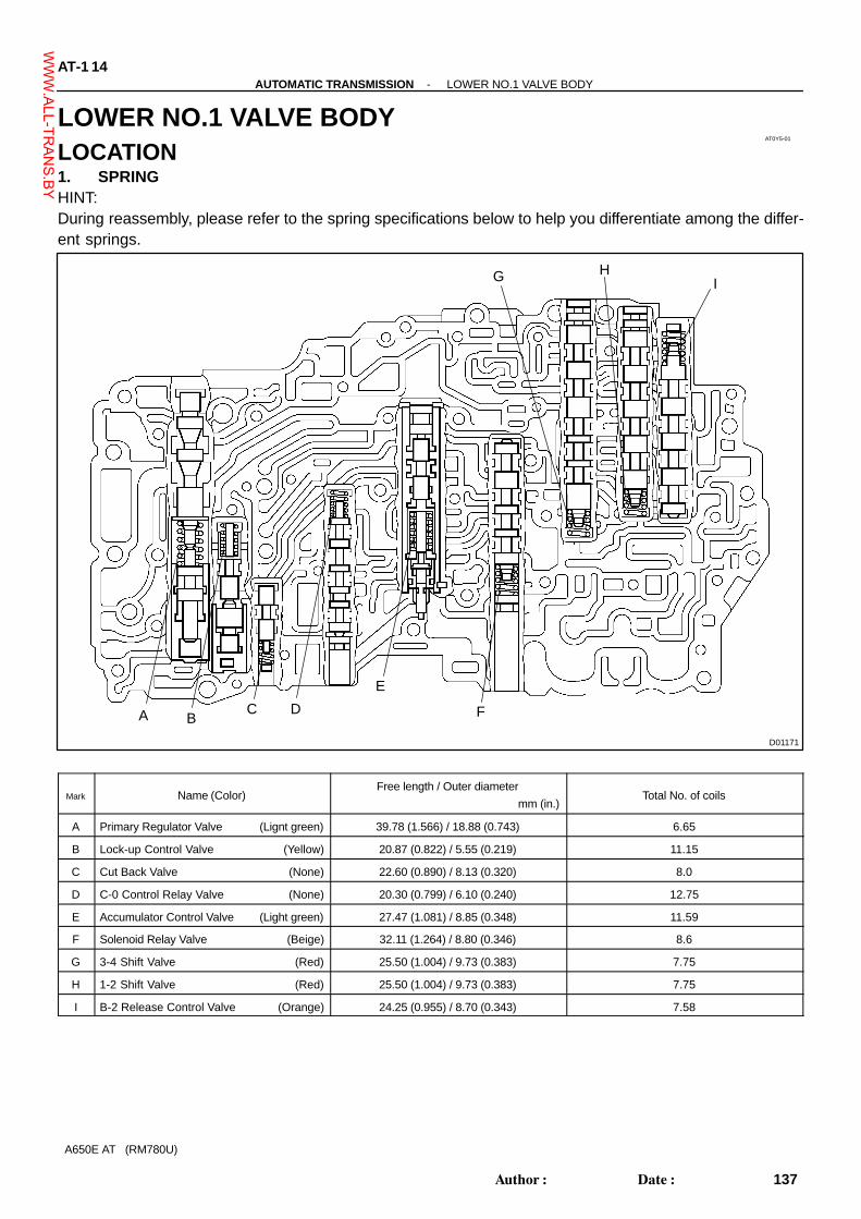
AT-1 14-AUTOMATIC TRANSMISSION LOWER NO.1 VALVE BODY
137Author�: Date�:
A650E AT (RM780U)
LOWER NO.1 VALVE BODYLOCATION1. SPRINGHINT:During reassembly, please refer to the spring specifications below to help you differentiate among the differ-ent springs.
Mark Name (Color)Free length / Outer diameter
mm (in.)Total No. of coils
A Primary Regulator Valve (Lignt green) 39.78 (1.566) / 18.88 (0.743) 6.65
B Lock-up Control Valve (Yellow) 20.87 (0.822) / 5.55 (0.219) 11.15
C Cut Back Valve (None) 22.60 (0.890) / 8.13 (0.320) 8.0
D C-0 Control Relay Valve (None) 20.30 (0.799) / 6.10 (0.240) 12.75
E Accumulator Control Valve (Light green) 27.47 (1.081) / 8.85 (0.348) 11.59
F Solenoid Relay Valve (Beige) 32.11 (1.264) / 8.80 (0.346) 8.6
G 3-4 Shift Valve (Red) 25.50 (1.004) / 9.73 (0.383) 7.75
H 1-2 Shift Valve (Red) 25.50 (1.004) / 9.73 (0.383) 7.75
I B-2 Release Control Valve (Orange) 24.25 (0.955) / 8.70 (0.343) 7.58
WWW.ALL-TR
ANS.BY

D01175
AC
E
IG
BD
F
H
-AUTOMATIC TRANSMISSION LOWER NO.1 VALVE BODYAT-1 15
138Author�: Date�:
A650E AT (RM780U)
2. RETAINER
Mark RetainerHeight / Width / Thickness
mm (in.)
A Primary Regulator Valve - / - / 3.2 (0.126)
B Lock-up Control Valve 19.0 (0.748) / 5.0 (0.197) / 3.2 (0.126)
C Cut Back Valve 21.0 (0.827) / - / 3.2 (0.126)
D C-0 Control Relay Valve 8.5 (0.335) / 5.0 (0.197) / 3.2 (0.126)
E Accumulator Control Valve 29.0 (1.142) / 5.0 (0.197) / 3.2 (0.126)
F Solenoid Relay Valve 8.0 (0.315) / 8.0 (0.315) / 3.2 (0.126)
G 3-4 Shift Valve 8.0 (0.315) / 8.0 (0.315) / 3.2 (0.126)
H 1-2 Shift Valve 8.0 (0.315) / 8.0 (0.315) / 3.2 (0.126)
I B-2 Release Control Valve 21.0 (0.827) / - / 3.2 (0.126)
WWW.ALL-TR
ANS.BY

D01176
Check Ball
Orifice ControlThermal Valve
AT-1 16-AUTOMATIC TRANSMISSION LOWER NO.1 VALVE BODY
139Author�: Date�:
A650E AT (RM780U)
3. CHECK BALL AND ORIFICE CONTROL THERMAL VALVE
WWW.ALL-TR
ANS.BY

AT0Y6-01
D01172
A
AT-1 18-AUTOMATIC TRANSMISSION LOWER NO.2 VALVE BODY
141Author�: Date�:
A650E AT (RM780U)
LOWER NO.2 VALVE BODYLOCATION1. SPRINGHINT:During reassembly, please refer to the spring specifications below to help you differentiate among the differ-ent springs.
Mark Name (Color)Free length / Outer diameter
mm (in.)Total No. of coils
A Reverse Control Valve (None) 25.58 (1.007) / 8.64 (0.340) 8.75WWW.ALL-TR
ANS.BY

D01177
A
-AUTOMATIC TRANSMISSION LOWER NO.2 VALVE BODYAT-1 19
142Author�: Date�:
A650E AT (RM780U)
2. RETAINER
Mark RetainerHeight / Width / Thickness
mm (in.)
A Reverse Control Valve 8.5 (0.335) / 5.0 (0.197) / 3.2 (0.126)
WWW.ALL-TR
ANS.BY

AT04A-02
D09398
O/D Brake (B0)
O/D One-wayClutch (F0)
3rd Coast Brake (B1)Direct Clutch (C2)
Forward Clutch (C1)
No. 1 One-way Clutch (F1)2nd Brake (B3)
1st & Reverse Brake (B4)No. 2 One-way Clutch (F2)
3rd Brake (B2)
O/D Direct Clutch (C0)
Shift Solenoid Valve No. 4
Shift Solenoid Valve No. 3Shift Solenoid Valve No. 1
Shift Solenoid Valve No. 2
Shift Solenoid Valve SLT
Shift Solenoid Valve SLUShift Solenoid Valve SLN
ParkReverseNeutral
1st2nd
4th5th1st
3rd1st
1st
S1 S2 S3 C0 C1 C2 B0 B1 B2 B3 B4 F0 F1 F2
: Operating
GearPosition
Shift LeverPosition
OFF
ON
ON
ON
ON
ONON
ON
ONON
OFF
OFFOFF
OFF
OFF
OFF
OFF
OFFOFFONONOFFOFF
ONON
OFFOFFON OFF
OFF OFFOFF ON
2nd
2nd
3rd
S4
ON OFF ON
OFFON ON
ON
OFFOFFOFFOFFOFF
OFFOFFOFFOFFOFFOFF
RN
D M (5)*
3
2
L
P
OFF ON OFF
OFFOFF
* : When the shift lever position is ”M” and the gear position indicator shows ”5”.
-AUTOMATIC TRANSMISSION AUTOMATIC TRANSMISSION SYSTEMAT-1
24Author�: Date�:
A650E AT (RM780U)
AUTOMATIC TRANSMISSION SYSTEMOPERATION
WWW.ALL-TR
ANS.BY

D01427
IN
C1
C2
B2
F1
B1
B4
F2B0
F0C0
B3
OUT
AT-2-AUTOMATIC TRANSMISSION AUTOMATIC TRANSMISSION SYSTEM
25Author�: Date�:
A650E AT (RM780U)
FUNCTION OF COMPONENTS
Component Function
C0 O/D Direct Clutch Connects O/D sun gear & O/D planetary carrier.
C1 Forward Clutch Connects input shaft and rear planetary sun gear.
C2 Direct Clutch Connects input shaft and front & center planetary sun gear.
B0 O/D BrakePrevents O/D sun gear from turning either clockwise or coun-
terclockwise.
B1 3rd Coast BrakePrevents front & center planetary sun gear from turning either
clockwise or counterclockwise.
B2 3rd Brake
Prevents outer race of F1 from turning either clockwise or
counterclockwise thus preventing the front & center planetary
sun gear from turning counterclockwise.
B3 2nd BrakePrevents front planetary carrier from turning either clockwise
or counterclockwise.
B4 1st & Reverse BrakePrevents rear planetary ring gear from turning either clockwise
or counterclockwise.
F0 O/D One-way ClutchWhen the transmission is being driven by the engine, this
clutch connects the O/D sun gear and O/D planetary carrier.
F1 No.1 One-way ClutchWhen B2 is operating, this clutch prevents the front & center
planetary sun gear from turning counterclockwise.
F2 No.2 One-way Clutch Prevents rear planetary ring gear from turning clockwise.
WWW.ALL-TR
ANS.BY

AT04E-01
D01289
SST
D01292
DriveGear
DrivenGear
D01293
D01294
D01295
AT-44-AUTOMATIC TRANSMISSION OIL PUMP
67Author�: Date�:
A650E AT (RM780U)
REASSEMBLY1. INSTALL OIL SEAL(a) Using SST, install a new oil seal.HINT:The oil seal end should be flush with the outer edge of the pumpbody.
SST 09350-30020 (09351-32140)(b) Coat the oil seal lip with MP grease.
2. INSTALL DRIVEN GEAR AND DRIVE GEAR TO OILPUMP BODY
(a) Place the oil pump body on the torque converter clutch.(b) Coat the driven gear and drive gear with ATF.(c) Install the driven gear and drive gear.
3. INSTALL STATOR SHAFT TO OIL PUMP BODY(a) Align the stator shaft with each bolt hole.(b) Install the 13 bolts.
Torque: 10 N·m (100 kgf·cm, 7 ft·lbf)
4. INSTALL OIL SEAL RINGS(a) Coat the 2 oil seal rings with ATF.(b) Install the 2 oil seal rings to the stator shaft groove, then
snug them down by squeezing their ends together.NOTICE:Do not spread the ring ends too much.HINT:After installing the oil seal rings, check that they rotate smooth-ly.
5. CHECK OIL PUMP DRIVE GEAR ROTATIONMake sure the drive gear rotates smoothly.
WWW.ALL-TR
ANS.BY

AT04I-02
D01301
D01299
Piston
Spring
Retainer
Piston Rod
D01298
D01302
AT-48-AUTOMATIC TRANSMISSION THIRD COAST BRAKE
71Author�: Date�:
A650E AT (RM780U)
REASSEMBLY1. SELECT PISTON RODIf the band is OK with piston rod stroke not within the standardvalue, select a new piston rod.HINT:There are 5 different lengths for piston rod.Piston rod length: mm (in.)
77.65 (3.057) 79.90 (3.146)
78.40 (3.087) 80.65 (3.175)
79.15 (3.116) -
2. ASSEMBLE 3RD COAST BRAKE PISTON(a) Install the retainer, compression spring and piston to the
piston rod.
(b) Firmly hold down the piston, then compress the compres-sion spring.
(c) Install the E-ring.
3. INSTALL 3RD COAST BRAKE PISTON OIL SEALRING
(a) Coat the oil seal ring with ATF.(b) Install the oil seal ring to the piston groove, then snug it
down by squeezing its ends together.NOTICE:Do not spread the ring ends more than necessary.
WWW.ALL-TR
ANS.BY

AT0Y3-01
D09430
SST
D09431
SST
AT-102-AUTOMATIC TRANSMISSION EXTENSION HOUSING
125Author�: Date�:
A650E AT (RM780U)
REASSEMBLY1. INSTALL NEW EXTENSION HOUSING OIL SEAL(a) Using SST and a hammer, carefully drive a new oil seal
in as far as it will go.SST 09325-20010
NOTICE:Clean the extension housing before removing the oil seal.(b) Coat the lip of a new oil seal with MP grease.
2. INSTALL NEW EXTENSION HOUSING DUST DEFLEC-TOR
Using SST and hammer, carefully drive a new dust deflector inas far as it will go.
SST 09223-15030, 09950-70010 (09951-07100)
WWW.ALL-TR
ANS.BY

AT05J-02
D01259
Plate
D01254
D01253
AA B C B
C
C
DAB
D
C
B
D01261
Check Ball
Orifice ControlThermal Valve
-AUTOMATIC TRANSMISSION VALVE BODYAT-107
130Author�: Date�:
A650E AT (RM780U)
REASSEMBLY1. INSTALL PLATE ON UPPER VALVE BODY(a) Align the plate with each bolt hole and install the 2 screws.(b) Install the 2 strainers.
2. PLACE UPPER VALVE BODY WITH PLATE ON TOPOF NO. 1 LOWER VALVE BODY
(a) Install the spring and check valve.(b) Align the plate in the valve body with each bolt hole.
3. INSTALL UPPER VALVE BODY TO NO. 1 LOWERVALVE BODY WITH 30 BOLTS
Install the plate from the upper valve body.Torque: 6.4 N·m (65 kgf·cm, 56 in.·lbf)
HINT:Each bolts length is indicated below.
Bolt length: Bolt A: 40 mm (1.575 in.)Bolt B: 35 mm (1.378 in.)Bolt C: 28 mm (1.102 in.)Bolt D: 20 mm (0.787 in.)
4. INSTALL THE LOWER NO. 2 VALVE BODY ANDPLATE TO LOWER NO. 1 VALVE BODY
(a) Install the check ball and orifice control thermal valve.(b) Install the strainer.
WWW.ALL-TR
ANS.BY

D01252
Plate
Lower No. 2Valve Body
D01251
BA
B
A
B
D01247
A
B
A
B
B
D01248Manual Valve
AT-108-AUTOMATIC TRANSMISSION VALVE BODY
131Author�: Date�:
A650E AT (RM780U)
(c) Align the holes of lower No. 2 valve body with those ofplate and place them on the lower No. 1 valve body withaligning all the holes.
(d) Install the 12 bolts. 2 of them are attached to the oil coolerpipe and clamp. So install them all together.Torque: 6.4 N·m (65 kgf·cm, 56 in.·lbf)
HINT:Each bolts length is indicated below.
Bolt length: Bolt A: 28 mm (1.102 in.)Bolt B: 20 mm (0.787 in.)
5. INSTALL 7 SOLENOIDS(a) Coat 6 new O-rings with ATF and install them on the shift
solenoid No. 1, No. 2, No. 3 and No. 4.(b) Install the shift solenoid valve S1 and the bolt.(c) Install the shift solenoid valve S3 with the bolt.(d) Install the shift solenoid valve S2 with the bolt.(e) Install the shift solenoid valve S4.(f) Install the shift solenoid valve SLN, and No. 1 solenoid
lock plate.(g) Install the oil guide plate with the 2 bolts.(h) Install the shift solenoid valve SLU, SLT, and No. 2 sole-
noid lock plate with the bolt.(i) Install the ball, spring, pressure relief valve spring seat
and bolt.Torque:Bolt A: 6.4 N·m (65 kgf·cm, 56 in.·lbf)Bolt B: 9.8 N·m (100 kgf·cm, 7 ft·lbf)
6. INSTALL MANUAL VALVE
WWW.ALL-TR
ANS.BY

D01249
-AUTOMATIC TRANSMISSION VALVE BODYAT-109
132Author�: Date�:
A650E AT (RM780U)
7. INSTALL DETENT SPRING AND SPRING PLATETorque: 9.8 N·m (100 kgf·cm, 7 ft·lbf)
8. MAKE SURE MANUAL VALVE MOVES SMOOTHLY
WWW.ALL-TR
ANS.BY

AT0Y0-01
-AUTOMATIC TRANSMISSION COMPONENT PARTSAT-19
42Author�: Date�:
A650E AT (RM780U)
REASSEMBLYNOTICE:� The automatic transaxle is composed of highly precision-finished parts, necessitating careful
inspection before reassembly because even a small nick could cause fluid leakage or affectthe performance. The instructions here are organized so that you work on only one componentgroup at a time. This will help avoid confusion from similar-looking parts of different sub-as-semblies being on your workbench at the same time. The component groups are inspected andrepaired from the converter housing side. As much as possible, complete the inspection, repairand reassembly before proceeding to the next component group. If a defect is found in a certaincomponent group during reassembly, inspect and repair this group immediately. If a compo-nent group cannot be assembled because parts are being ordered, be sure to keep all parts ofthe group in a separate container while proceeding with disassembly, inspection, repair andreassembly of other component groups.Recommended ATF: Type T-IV
� All disassembled parts should be washed clean and any fluid passages and holes should beblown through with compressed air.
� Dry all parts with compressed air-never use shop rags.� When using compressed air, always aim away from yourself to prevent accidentally spraying
ATF or kerosene on your face.� The recommended automatic transaxle fluid or kerosene should be used for cleaning.� After cleaning, the parts should be arranged in the correct order for efficient inspection, repairs,
and reassembly.� When disassembling a valve body, be sure to match each valve together with the correspond-
ing spring.� New discs for the brakes and clutches that are to be used for replacement must be soaked in
ATF for at least 15 minutes before reassembly.� All oil seal rings, clutch discs, clutch plates, rotating parts, and sliding surfaces should be
coated with ATF prior to reassembly.� All gaskets and rubber O-rings should be replaced.� Do not apply adhesive cements to gaskets and similar parts.� Make sure that the ends of a snap ring are not aligned with one of the cutouts and are installed
in the groove correctly.� If a worn bushing is to be replaced, the sub-assembly containing the bushing must also be re-
placed.� Check thrust bearings and races for wear or damage. Replace if necessary.� Use petroleum jelly to keep parts in place.� When working with FIPG material, you must observe the following.
Using a razor blade and a gasket scraper, remove all the old packing (FIPG) material from thegasket surface.Thoroughly clean all components to remove all the loose material.Clean both sealing surfaces with a non-residue solvent.Parts must be reassembled within 10 minutes of application. Otherwise, the packing (FIPG) ma-terial must be removed and reapplied.
WWW.ALL-TR
ANS.BY

D01470
A
B C
E
D
F
G
H
AT-20-AUTOMATIC TRANSMISSION COMPONENT PARTS
43Author�: Date�:
A650E AT (RM780U)
BEARING AND RACES INSTALLATION POSITION AND DIRECTION
MarkFront Race Diameter
Inside / Outside mm (in.)
Thrust Bearing Diameter
Inside / Outside mm (in.)
Rear Race Diameter
Inside / Outside mm (in.)
A 28.1 (1.106) / 47.5 (1.870) 28.8 (1.134) / 50.4 (1.984) -
B 27.2 (1.070) / 42.0 (1.654) 25.9 (1.020) / 47.0 (1.850) 24.0 (0.945) / 48.0 (1.890)
C 37.1 (1.461) / 59.0 (2.323) 33.6 (1.323) / 50.3 (1.980) -
D 37.0 (1.457) / 51.0 (2.008) 33.5 (1.319) / 47.8 (1.882) -
E 26.2 (1.031) / 41.1 (1.618) 26.3 (1.035) / 44.0 (1.732) -
F 32.5 (1.280) / 59.0 (2.323) 43.5 (1.712) / 59.8 (2.354) 43.5 (1.712) / 61.5 (2.421)
G 39.2 (1.543) / 56.8 (2.236) 40.7 (1.602) / 57.0 (2.244) 41.2 (1.620) / 59.8 (2.354)
H - 52.9 (2.083) / 70.6 (2.780) -
WWW.ALL-TR
ANS.BY

D01423
D01451
Front
D01166
D01165
SST
D01192
Front
-AUTOMATIC TRANSMISSION COMPONENT PARTSAT-21
44Author�: Date�:
A650E AT (RM780U)
1. INSTALL TRANSMISSION CASE ON OVERHAUL AT-TACHMENT
2. INSTALL REAR PLANETARY RING GEAR(a) Install the assembled bearing & race.Assembled bearing & race diameter: mm (in.)
Inside Outside
Assembled bearing & race 52.9 (2.083) 70.6 (2.780)
(b) Install the rear planetary ring gear.
(c) Using SST, install the snap ring.SST 09350-30020 (09350-07070)
3. INSTALL OUTPUT SHAFT WITH CENTER AND REARPLANETARY GEAR
(a) Install the 2 races and bearing onto the rear planetary ringgear.
Bearing and race diameter: mm (in.)
Inside Outside
Race 39.2 (1.543) 56.8 (2.236)
Bearing 40.7 (1.602) 57.0 (2.244)
Race 41.2 (1.620) 59.8 (2.354)
WWW.ALL-TR
ANS.BY

D01164
Thrust Washer
D01255
D09452Flange
P
P
P
P
D
D
D
DSpring
D
D01555
AT-22-AUTOMATIC TRANSMISSION COMPONENT PARTS
45Author�: Date�:
A650E AT (RM780U)
(b) Install the thrust washer to the output shaft with center &rear planetary gear.
(c) Install the output shaft with center & rear planetary gear.
4. INSTALL FRONT PLANETARY GEAR(a) Install the spring to the case.(b) Install the 2nd brake pack (4 plates, 5 discs and flange).
Install in order: P = Plate, D = DiscD - P - D - P - D - P - D - P - DFlange thickness: mm (in.)
No. Thickness No. Thickness
21 2.1 (0.083) 27 2.7 (0.106)
23 2.3 (0.091) 29 2.9 (0.114)
25 2.5 (0.098) 31 3.1 (0.122)
(c) Install the front & center planetary sun gear from the case.
WWW.ALL-TR
ANS.BY

D01556
D01554
D01570
D01491
D01492
-AUTOMATIC TRANSMISSION COMPONENT PARTSAT-23
46Author�: Date�:
A650E AT (RM780U)
(d) Coat the thrust washer, with petroleum jelly and install itonto front planetary gear.
(e) Install the front planetary gear and 2 washers from thecase.
5. INSTALL MULTIPLE DISC BRAKE AND NO. 1 ONE-WAY CLUTCH
(a) Lay the transmission case.
(b) Install the multiple disc brake to the case.
(c) Install the No. 1 one-way clutch to the multiple disc brake.
WWW.ALL-TR
ANS.BY

D01160SST
D01168
D01198
D01199
D01200
Front
AT-24-AUTOMATIC TRANSMISSION COMPONENT PARTS
47Author�: Date�:
A650E AT (RM780U)
(d) Using SST, install the snap ring.SST 09350-30020 (09350-07060)
6. INSTALL BRAKE DRUM GASKET(a) Coat 2 new gaskets with ATF.(b) Install the 2 brake drum gaskets.
7. INSTALL SUN GEAR INPUT DRUM(a) Install the thrust washer.
(b) Install the sun gear input drum.
(c) Coat the bearing, 2 races with petroleum jelly and installthem onto the sun gear input drum.
Bearing and race diameter: mm (in.)
Inside Outside
Race 32.5 (1.280) 59.0 (2.323)
Bearing 43.5 (1.712) 59.8 (2.354)
Race 43.5 (1.712) 61.5 (2.421)
WWW.ALL-TR
ANS.BY

D01157
D01265
D01266
D09423
Race
AssembledBearing & Race
D01155
AssembledBearing & Race
Thrust Washer
-AUTOMATIC TRANSMISSION COMPONENT PARTSAT-25
48Author�: Date�:
A650E AT (RM780U)
8. INSTALL 3RD COAST BRAKE BAND(a) Install the 3rd coast brake band to the transmission case.
(b) Install the E-ring to the pin.(c) Install the pin through the brake band.
(d) Using a needle nose plier, install the E-ring to the pin.
9. INSTALL DIRECT CLUTCH WITH FORWARD CLUTCH(a) Coat the assembled bearing & race, race with petroleum
jelly and install them onto the forward clutch hub.Assembled bearing & race and diameter: mm (in.)
Inside Outside
Assembled bearing & race 26.3 (1.035) 44.0 (1.732)
Race 26.2 (1.031) 41.1 (1.618)
(b) Install the assembled bearing & race and thrust washerto the forward clutch.
Assembled bearing & race diameter: mm (in.)
Inside Outside
Assembled bearing & race 33.5 (1.319) 47.8 (1.882)
WWW.ALL-TR
ANS.BY

D09424
Forward Clutch
ForwardClutch Hub
DirectClutch
D01493
D01372
D01152
O-Ring
D01377
SST
AT-26-AUTOMATIC TRANSMISSION COMPONENT PARTS
49Author�: Date�:
A650E AT (RM780U)
(c) Install the direct clutch and forward clutch hub to the for-ward clutch.
(d) Insert the direct clutch with forward clutch to the case.
(e) With the case set upright, using vernier calipers, measurethe distance between the sun gear input drum and directclutch drum.Height: 4.1 - 6.0 mm (0.161 - 0.236 in.)
If the height is non-standard, check for improper installation.
10. INSTALL 3RD COAST BRAKE COVER, PISTON AS-SEMBLY AND SPRING
(a) Coat 2 new O-rings with ATF and install them to the cover.(b) Install the spring, piston and cover to the case.
(c) Using SST, install the snap ring.SST 09350-30020 (09350-07060)
WWW.ALL-TR
ANS.BY
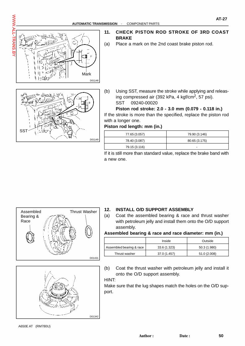
D01148
Mark
D01149
SST
D01431
AssembledBearing &Race
Thrust Washer
D01342
-AUTOMATIC TRANSMISSION COMPONENT PARTSAT-27
50Author�: Date�:
A650E AT (RM780U)
11. CHECK PISTON ROD STROKE OF 3RD COASTBRAKE
(a) Place a mark on the 2nd coast brake piston rod.
(b) Using SST, measure the stroke while applying and releas-ing compressed air (392 kPa, 4 kgf/cm2, 57 psi).SST 09240-00020Piston rod stroke: 2.0 - 3.0 mm (0.079 - 0.118 in.)
If the stroke is more than the specified, replace the piston rodwith a longer one.Piston rod length: mm (in.)
77.65 (3.057) 79.90 (3.146)
78.40 (3.087) 80.65 (3.175)
79.15 (3.116) -
If it is still more than standard value, replace the brake band witha new one.
12. INSTALL O/D SUPPORT ASSEMBLY(a) Coat the assembled bearing & race and thrust washer
with petroleum jelly and install them onto the O/D supportassembly.
Assembled bearing & race and race diameter: mm (in.)
Inside Outside
Assembled bearing & race 33.6 (1.323) 50.3 (1.980)
Thrust washer 37.0 (1.457) 51.0 (2.008)
(b) Coat the thrust washer with petroleum jelly and install itonto the O/D support assembly.
HINT:Make sure that the lug shapes match the holes on the O/D sup-port.
WWW.ALL-TR
ANS.BY

D01378
SST
D01379
D01145
SST
D01380
AT-28-AUTOMATIC TRANSMISSION COMPONENT PARTS
51Author�: Date�:
A650E AT (RM780U)
(c) Using 2 bolts of SST, face the bolt and oil holes of the O/Dsupport toward the valve body side, align them with thebolt holes of the transmission case and install the bolts.SST 09350-30020 (09350-07020)
(d) Install the 2 bolts.Torque: 25 N·m (260 kgf·cm, 19 ft·lbf)
(e) Using SST, install the snap ring.SST 09350-30020 (09350-07060)
13. CHECK OUTPUT SHAFT(a) Using a dial indicator, measure the end play of the output
shaft with hand.End play: 1.63 - 2.89 mm (0.064 - 0.114 in.)
If the values are non-standard, check for improper installation.(b) Check to see that output shaft rotates smoothly.
WWW.ALL-TR
ANS.BY

D09420
D
DP
Flange
D
P
P
Spring
D01140
D01147
SST
-AUTOMATIC TRANSMISSION COMPONENT PARTSAT-29
52Author�: Date�:
A650E AT (RM780U)
14. INSTALL FLANGES, PLATES AND DISCS OF O/DBRAKE
(a) Install the 4.0 mm (0.157 in.) thick flange (flat ring )with therounded-edge side of the flange facing the disc.
(b) Install the O/D brake pack.HINT:3 plates, 3 discs and flange
Install in order: P = Plate, D = DiscP - D - P - D - P - D
(c) Install the flange (stepped ring) with the flat side of theflange facing the disc.
(d) Install the spring to the case.
(e) Using a screwdriver, install the snap ring.NOTICE:Be sure the end gap of the snap ring is not aligned with cut-out portion of the brake drum.
15. CHECK PISTON STROKE OF O/D BRAKE(a) Place SST and a dial indicator onto the O/D brake piston.
SST 09350-30020 (09350-06120)
WWW.ALL-TR
ANS.BY

D01141
D01382
Race
D01137
D01383
AT-30-AUTOMATIC TRANSMISSION COMPONENT PARTS
53Author�: Date�:
A650E AT (RM780U)
(b) Measure the stroke while applying and releasing com-pressed air (392 kPa, 4 kgf/cm2, 57 psi).Piston Stroke: 1.32 - 1.62 mm (0.052 - 0.064 in.)
If the piston stroke is less than the limit, parts may have beenassembled incorrectly, so check and reassemble again.If the piston stroke is non-standard, select another flange.HINT:There are 7 different thickness for the flange.Flange thickness: mm (in.)
No. Thickness No. Thickness
77 3.3 (0.130) 81 3.8 (0.150)
78 3.5 (0.138) 82 3.9 (0.154)
79 3.6 (0.142) 83 4.0 (0.157)
80 3.7 (0.146) - -
16. INSTALL O/D PLANETARY GEAR UNIT WITH O/D DI-RECT CLUTCH & O/D ONE-WAY CLUTCH
(a) Coat the race with petroleum jelly and install it onto theO/D planetary ring gear.
Race diameter: mm (in.)
Inside Outside
Race 37.1 (1.461) 59.0 (2.323)
(b) Install the O/D planetary ring gear.
(c) Install the bearing and race onto the O/D planetary ringgear.
Bearing and race diameter: mm (in.)
Inside Outside
Bearing 25.9 (1.020) 47.0 (1.850)
Race 24.0 (0.945) 48.0 (1.890)
WWW.ALL-TR
ANS.BY

D01384
Race
D01135
D01385
D01386
Race
-AUTOMATIC TRANSMISSION COMPONENT PARTSAT-31
54Author�: Date�:
A650E AT (RM780U)
(d) Coat the race with petroleum jelly and install it onto theO/D planetary gear.
Race diameter: mm (in.)
Inside Outside
Race 27.2 (1.071) 42.0 (1.654)
(e) Install the O/D planetary gear with the O/D direct clutch& O/D one-way clutch.
(f) Install the assembled bearing & race onto the O/D directclutch.
Assembled bearing & race diameter: mm (in.)
Inside Outside
Assembled bearing & race 28.8 (1.134) 50.4 (1.984)
17. INSTALL OIL PUMP INTO CASE(a) Coat the race with petroleum jelly and install it onto the oil
pump.Race diameter: mm (in.)
Inside Outside
Race 28.1 (1.106) 47.5 (1.870)
(b) Coat a new O-ring with ATF and install it around the pumpbody.
(c) Place the oil pump through the input shaft, and align thebolt holes of the pump body with the transmission case.
(d) Hold the input shaft, and lightly press the oil pump bodyto slide the oil seal rings into the overdrive direct clutchdrum.
NOTICE:Do not push on the oil pump strongly, or the oil seal ring willstick to the direct clutch drum.
WWW.ALL-TR
ANS.BY
D01387
D01388
D01203
(1) (2) (3)
(4)
(5)
(6)
(7)
C0 AccumulatorPiston hole
D01389
SST
AT-32-AUTOMATIC TRANSMISSION COMPONENT PARTS
55Author�: Date�:
A650E AT (RM780U)
(e) Install the 7 bolts.Torque: 21 N·m (215 kgf·cm, 16 ft·lbf)
18. CHECK INPUT SHAFT ROTATIONMake sure the input shaft rotates smoothly.
19. INDIVIDUAL PISTON OPERATION INSPECTIONCheck for the sound of operation while applying compressed airinto the oil holes indicated in the illustration.HINT:When inspecting the O/D direct clutch, check with the C0 accu-mulator piston hole closed.If there is no noise, disassemble and check the installationcondition of the parts.
(1) Forward clutch(2) Direct clutch(3) O/D brake(4) 3rd coast brake(5) 3rd brake(6) 2nd brake(7) 1st & reverse brake
20. INSTALL MANUAL VALVE LEVER, SHAFT AND OILSEAL
(a) Using SST, drive in a 2 new oil seals.SST 09350-30020 (09350-07110)
(b) Coat the oil seal lip with MP grease.
WWW.ALL-TR
ANS.BY

D01390
Spacer
ManualValve Lever
D01393
D01184
D01394
Spring
E-Ring
ParkingLock Pawl
D01395
-AUTOMATIC TRANSMISSION COMPONENT PARTSAT-33
56Author�: Date�:
A650E AT (RM780U)
(c) Install a new spacer to the manual valve lever.(d) Install the manual valve lever shaft to the transmission
case through the manual valve lever.
(e) Using a hammer, drive in a new spring pin.
(f) Match the manual valve lever indentation with the spacerhole and stake them together with the punch.
(g) Make sure the shaft rotates smoothly.
21. INSTALL PARKING LOCK PAWL AND ROD(a) Install the E-ring to the shaft.(b) Install the parking lock pawl, shaft and spring.
(c) Connect the parking lock rod to the manual valve lever.
WWW.ALL-TR
ANS.BY

D09419
D01397Lock Pawl
ManualValveLever
PlanetaryRing Gear
D01204
B2
C2
B0C0
D01205
(1) (2) (3) (4)
B2 C2 B0 C0
AT-34-AUTOMATIC TRANSMISSION COMPONENT PARTS
57Author�: Date�:
A650E AT (RM780U)
(d) Place the parking lock pawl bracket onto the transmissioncase and torque the 3 bolts.Torque: 7.4 N·m (75 kgf·cm, 65 in.·lbf)
(e) Shift the manual valve lever to the P position, and confirmthe planetary ring gear is correctly locked up by the lockpawl.
22. INSTALL ACCUMULATOR SPRINGS AND PISTONS(a) Coat new O-rings with ATF and install them to the pis-
tons.(b) Install the 4 springs and 4 accumulator pistons to the
holes.HINT:The pistons are marked in relief with either C0, B0, C2 or B2 todiscriminate each other.
Accumulator spring:
Spring
Free length
Outer diameter
mm (in.)
Color
(1) B280.91 (3.185)
19.97 (0.786)Pink & white
(2) C2 Inner 41.00 (1.614)
14.10 (0.555)Orange
Outer 75.20 (2.961)
20.10 (0.791)White & Blue
(3) B069.40 (2.732)
16.25 (0.640)White
(4) C065.00 (2.559)
20.59 (0.811)None
WWW.ALL-TR
ANS.BY

D01128
Check Ball Body
Spring
D01460
Pin
D01461
A
C
D
B
C
B A B
B
C
B
D01122
StopperPlate
D09389
Clamp
-AUTOMATIC TRANSMISSION COMPONENT PARTSAT-35
58Author�: Date�:
A650E AT (RM780U)
23. INSTALL SPRING AND CHECK BALL BODY
24. INSTALL VALVE BODY(a) Align the groove of the manual valve with the pin of the
lever.
(b) Install the 20 bolts.Torque: 9.8 N·m (100 kgf·cm, 7 ft·lbf)
HINT:Each bolt length is indicated below.
Blot length:Bolt A: 23 mm (0.866 in.)Bolt B: 28 mm (1.102 in.)Bolt C: 36 mm (1.417 in.)Bolt D: 55 mm (2.165 in.)
25. INSTALL TRANSMISSION WIRE(a) Coat a new O-ring with ATF and install it to the transmis-
sion wire.(b) Insert the transmission wire to the case and install the
stopper plate with the bolt.Torque: 5.4 N·m (55 kgf·cm, 48 in.·lbf)
(c) Connect the 7 solenoid connectors.(d) Install the ATF temperature sensor.(e) Install the clamp and bolt.
Torque: 6.4 N·m (65 kgf·cm, 56 in.·lbf)
WWW.ALL-TR
ANS.BY

D00753
Gasket
D09388
D00912Magnet
D01917
Seal Breadth 2 - 3 mm (0.08 - 0.12 in.)
D01400
’’A’’
AT-36-AUTOMATIC TRANSMISSION COMPONENT PARTS
59Author�: Date�:
A650E AT (RM780U)
26. INSTALL OIL STRAINER AND GASKET(a) Install new 3 gaskets to oil strainer.
(b) Install the oil strainer with the 4 bolts.Torque: 9.8 N·m (100 kgf·cm, 7 ft·lbf)
27. INSTALL OIL PAN(a) Install the 3 magnets in the oil pan.
(b) Remove any FIPG material and be careful not to drop oilon the contacting surfaces of the transmission case andoil pan.
(c) Apply FIPG to the oil pan.FIPG: Part No. 08826-00090, THREE BOND 1281 or equiva-lent
(d) Install and torque the 19 bolts.Torque: 7.4 N·m (75 kgf·cm, 65 in.·lbf)
HINT:Replace the only ’’A’’ bolt with a new one.
WWW.ALL-TR
ANS.BY
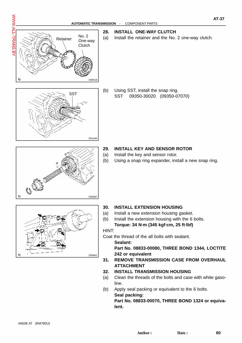
D09418
No. 2One-wayClutch
Retainer
D01445
SST
D09387
D04841
-AUTOMATIC TRANSMISSION COMPONENT PARTSAT-37
60Author�: Date�:
A650E AT (RM780U)
28. INSTALL ONE-WAY CLUTCH(a) Install the retainer and the No. 2 one-way clutch.
(b) Using SST, install the snap ring.SST 09350-30020 (09350-07070)
29. INSTALL KEY AND SENSOR ROTOR(a) Install the key and sensor rotor.(b) Using a snap ring expander, install a new snap ring.
30. INSTALL EXTENSION HOUSING(a) Install a new extension housing gasket.(b) Install the extension housing with the 6 bolts.
Torque: 34 N·m (345 kgf·cm, 25 ft·lbf)HINT:Coat the thread of the all bolts with sealant.
Sealant: Part No. 08833-00080, THREE BOND 1344, LOCTITE242 or equivalent
31. REMOVE TRANSMISSION CASE FROM OVERHAULATTACHMENT
32. INSTALL TRANSMISSION HOUSING(a) Clean the threads of the bolts and case with white gaso-
line.(b) Apply seal packing or equivalent to the 6 bolts.
Seal packing:Part No. 08833-00070, THREE BOND 1324 or equiva-lent.
WWW.ALL-TR
ANS.BY

D09417
A
B
A
D01111
D01404
D01405
7 ± 2°
D09455
AT-38-AUTOMATIC TRANSMISSION COMPONENT PARTS
61Author�: Date�:
A650E AT (RM780U)
(c) Install the transmission housing with the 6 bolts.Torque: A (14 mm bolt): 34 N·m (345 kgf·cm, 25 ft·lbf) B (17 mm bolt): 57 N·m (580 kgf·cm, 42 ft·lbf)
33. INSTALL VEHICLE SPEED SENSORS(a) Coat 2 new O-rings with ATF and install it to the speed
sensor.(b) Install the 2 vehicle speed sensors.(c) Install the bolts.
Torque: 5.4 N·m (55 kgf·cm, 48 in.·lbf)
34. INSTALL UNION AND ELBOW(a) Coat 2 new O-rings with ATF, install them to union and el-
bow.(b) Install the union.
Torque: 29 N·m (300 kgf·cm, 22 ft·lbf)
(c) Install the elbow.Torque: 29 N·m (300 kgf·cm, 22 ft·lbf)
35. INSTALL PARK/NEUTRAL POSITION SWITCH(a) Install the park/neutral position switch onto the manual
valve lever shaft and temporarily install the adjusting bolt.(b) Install the grommet and a new lock washer. Install and
torque the nut.Torque: 6.9 N·m (70 kgf·cm, 61 in.·lbf)
WWW.ALL-TR
ANS.BY

D10055
Neutral Position
D10056
Neutral Basic Line
Bolt
Groove
D10057
D09415
Control Shaft Lever
D01112
-AUTOMATIC TRANSMISSION COMPONENT PARTSAT-39
62Author�: Date�:
A650E AT (RM780U)
(c) Using the control shaft lever, fully turn the manual levershaft back and return 2 notches. It is now in neutral.
(d) Align the neutral basic line with the switch groove, andtighten the adjusting bolt.Torque: 13 N·m (130 kgf·cm, 9 ft·lbf)
(e) Using a screwdriver, bend the tabs of the lock washer.HINT:Bend at least 2 of the lock washer tabs.
36. INSTALL CONTROL SHAFT LEVERInstall the washer and nut to the control shaft lever.
Torque: 16 N·m (160 kgf·cm, 12 ft·lbf)
37. INSTALL BREATHER PIPEInstall the breather hose and bolt.
Torque: 5.4 N·m (55 kgf·cm, 48 in.·lbf)
WWW.ALL-TR
ANS.BY

AT04Q-02
D01338
D01336
O-Ring
O-Ring
D01339
D01340
PistonReturnSpring
-AUTOMATIC TRANSMISSION OVERDRIVE BRAKEAT-53
76Author�: Date�:
A650E AT (RM780U)
REASSEMBLY1. INSTALL OIL SEAL RING(a) Coat the 2 oil seal rings with ATF.(b) Install the 2 oil seal rings to the O/D support groove, then
snug them sown by squeezing their ends together.NOTICE:Do not spread the ring ends more than necessary.HINT:After installing the oil seal rings, check that they rotate smooth-ly.
2. INSTALL O/D BRAKE PISTON(a) Coat 2 new O-rings with ATF and install them in the O/D
brake piston.
(b) Being careful not to damage the O-rings, press in thebrake piston into the O/D support with both hands.
3. INSTALL PISTON RETURN SPRING(a) Install the piston return spring.
WWW.ALL-TR
ANS.BY

D09435
SST
D01557
A
B
D01342
D01333
AT-54-AUTOMATIC TRANSMISSION OVERDRIVE BRAKE
77Author�: Date�:
A650E AT (RM780U)
(b) Place SST on the spring retainer, and compress the re-turn spring with a shop press.SST 09387-00100
(c) Install the snap ring with a screwdriver.NOTICE:Be sure the end gap of the snap ring is not aligned with thecutout portion of the O/D support.
HINT:After assembling the O/D support assembly completely, alignthe position of the piston with the position shown in the illustra-tion ’’A’’.Align the end gap of the snap ring as shown in the illustration’’B’’.Make sure that the snap ring is not on the part of return springwhich prevents the spring from coming off. Check this on 8places.
4. INSTALL CLUTCH DRUM THRUST WASHERCoat the thrust washer with petroleum jelly and install it into theO/D support.HINT:Make sure that the lugs shapes match the holes on the O/D sup-port.
5. CHECK PISTON OPERATION OF O/D BRAKE(a) Place the O/D support assembly onto the direct clutch as-
sembly.(b) Apply compressed air (392 kPa, 4 kgf/cm2, 57 psi) into the
oil passage as shown, and be sure that the O/D brake pis-ton moves smoothly.
WWW.ALL-TR
ANS.BY

AT04M-02
D01429
ThrustWasher
Groove
D01321
FlangeSide
D01322
FlangeSide
D01323
D01312
AT-62-AUTOMATIC TRANSMISSION OVERDRIVE DIRECT CLUTCH
85Author�: Date�:
A650E AT (RM780U)
REASSEMBLY1. INSTALL O/D ONE-WAY CLUTCH(a) Install the thrust washer to the O/D planetary gear, the
grooved side facing upward.
(b) Install the one-way clutch and 2 inner races into the outerrace with the flange side of the one-way clutch facing up-ward.
(c) Install the O/D one-way clutch with the outer race to theO/D planetary gear.
(d) Install the retaining plate.(e) Using a screwdriver, install the snap ring.
2. INSTALL RING GEAR FLANGE TO O/D PLANETARYRING REAR
(a) Install the ring gear flange.(b) Using a screwdriver, install the snap ring.
WWW.ALL-TR
ANS.BY

D01324
O-Ring
O-Ring
D01325
D01310
PistonReturnSpring
D09440
SST
SST
D01328
D
DP 1
P 2
Flange
-AUTOMATIC TRANSMISSION OVERDRIVE DIRECT CLUTCHAT-63
86Author�: Date�:
A650E AT (RM780U)
3. INSTALL O/D DIRECT CLUTCH PISTON(a) Coat 2 new O-rings with ATF and install them on the O/D
direct clutch piston.
(b) Being careful not to damage the O-rings, press the directclutch piston into the clutch drum with both hands.
4. INSTALL PISTON RETURN SPRING(a) Install the piston return spring to the piston.
(b) Place SST on the spring retainer, and compress the re-turn spring with a press.SST 09387-00020
(c) Install the snap ring with SST.SST 09350-30020 (09350-07070)
NOTICE:Be sure the end gap of the snap ring is not aligned with thespring retainer claw.
5. INSTALL PLATES, DISCS AND FLANGE(a) Install the 2 plates and 2 discs.
Install in order: P = Plate, D = DiscP 1 - D - P 2 - D
(b) Install the flange, with the flat end facing downward.
WWW.ALL-TR
ANS.BY

D01329
D01305
TorqueConverterClutch
Oil Pump
D01489
SST
D01304
O/D Direct Clutch Assembly
AT-64-AUTOMATIC TRANSMISSION OVERDRIVE DIRECT CLUTCH
87Author�: Date�:
A650E AT (RM780U)
(c) Using a screwdriver, install the snap ring.
6. CHECK PISTON STROKE OF O/D DIRECT CLUTCH(a) Place the oil pump onto the torque converter clutch, then
place the O/D direct clutch assembly into the oil pump.
(b) Using SST and a dial indicator, measure the O/D directclutch piston stroke while applying and releasing com-pressed air (392 kPa, 4 kgf/cm2, 57 psi).SST 09350-30020 (09350-06120)Piston stroke: 0.85 - 1.10 mm (0.033 - 0.043 in.)
If the piston stroke is less than the limit of piston stroke, partsmay have been assembled incorrectly, so check and reas-semble again.If the stroke is non-standard, select another flange.HINT:There are 8 flanges in different thickness.Flange Thickness: mm (in.)
No. Thickness No. Thickness
23 3.8 (0.151) 18 3.4 (0.134)
22 3.7 (0.146) 19 3.3 (0.130)
16 3.6 (0.142) 20 3.2 (0.126)
17 3.5 (0.138) 21 3.1 (0.122)
7. INSTALL O/D DIRECT CLUTCH ASSEMBLY(a) Align the flukes of the discs in the direct clutch.(b) Install the direct clutch assembly onto the O/D planetary
gear.
WWW.ALL-TR
ANS.BY

D01303
Free
Turn
Lock
Hold
-AUTOMATIC TRANSMISSION OVERDRIVE DIRECT CLUTCHAT-65
88Author�: Date�:
A650E AT (RM780U)
8. CHECK OPERATION OF ONE-WAY CLUTCHHold the O/D direct clutch drum and turn the input shaft.Check that the input shaft turns freely clockwise and lockscounterclockwise.
WWW.ALL-TR
ANS.BY

AT04U-02
D01453
O-RingO-Ring
D01354
D01349
PistonReturnSpring
D09443
SST
SST
D09442
D
D
D
D
P
P
P
P
Flange
AT-70-AUTOMATIC TRANSMISSION DIRECT CLUTCH
93Author�: Date�:
A650E AT (RM780U)
REASSEMBLY1. INSTALL DIRECT CLUTCH PISTON TO DIRECT
CLUTCH DRUM(a) Coat 2 new O-rings with ATF and install them in the direct
clutch piston.
(b) Being careful not to damage the O-rings press in the di-rect clutch piston into the clutch drum with both hands.
2. INSTALL PISTON RETURN SPRING(a) Install the piston return spring.
(b) Place SST on the spring retainer, and compress the re-turn spring with a press.SST 09387-00020
(c) Using SST, install the snap ring.SST 09350-30020 (09350-07070)
NOTICE:Be sure the end gap of the snap ring is not aligned with thespring retainer claw.
3. INSTALL PLATE, DISC AND FLANGE(a) Install the cushion plate.(b) Install the 4 plates and 4 discs.
Install in order: P = Plate, D = DiscP - D - P - D - P - D - P - D
(c) Install the flange, the flat end facing downward.
WWW.ALL-TR
ANS.BY

D01346
D01344
D01345
SST
-AUTOMATIC TRANSMISSION DIRECT CLUTCHAT-71
94Author�: Date�:
A650E AT (RM780U)
(d) Using a screwdriver, install the snap ring.NOTICE:Be sure the end gap of the snap ring is not aligned with thecutout portion of the direct clutch drum.
4. CHECK PISTON STROKE OF DIRECT CLUTCH(a) Place the direct clutch assembly onto the O/D support as-
sembly.
(b) Using SST and a dial indicator, measure the direct clutchpiston stroke while applying and releasing compressedair (186 kPa, 1.9 kgf/cm2, 27 psi).SST 09350-30020 (09350-06120)Piston stroke: 0.40 - 0.70 mm (0.016 - 0.028 in.)
If the pack clearance is less than the limit of piston stroke, partsmay have been assembled incorrectly, so check and reas-semble again.If the clearance is non-standard, select another flange.HINT:There are 9 different flanges in thickness.Flange thickness: mm (in.)
No. Thickness No. Thickness
53 3.3 (0.130) 38 3.8 (0.150)
34 3.4 (0.134) 39 3.9 (0.154)
35 3.5 (0.138) 40 4.0 (0.157)
36 3.6 (0.142) 41 4.1 (0.161)
37 3.7 (0.146) - -
WWW.ALL-TR
ANS.BY

AT04Y-02
D01364
D01365
O-Ring
O-Ring
D01366
D01359
PistonReturnSpring
AT-76-AUTOMATIC TRANSMISSION FORWARD CLUTCH
99Author�: Date�:
A650E AT (RM780U)
REASSEMBLY1. INSTALL OIL SEAL RING(a) Coat the 3 oil seal rings with ATF.(b) Install the 3 oil seal rings to the forward clutch drum
groove, then snug them down by squeezing their ends to-gether.
NOTICE:Do not spread the ring ends more than necessary.HINT:After installing the oil seal rings, check that they rotate smooth-ly.
2. INSTALL FORWARD CLUTCH PISTON(a) Coat 2 new O-rings with ATF and install them on the for-
ward clutch piston.
(b) Being careful not to damage the O-rings, press the clutchpiston into the forward clutch drum with both hands.
3. INSTALL PISTON RETURN SPRING(a) Install the piston return spring.
WWW.ALL-TR
ANS.BY
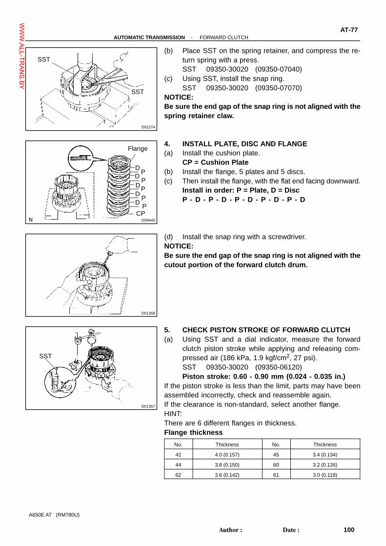
D01274
SST
SST
D09445
P
P
PP
P
D
D
D
D
D
Flange
CP
D01358
D01357
SST
-AUTOMATIC TRANSMISSION FORWARD CLUTCHAT-77
100Author�: Date�:
A650E AT (RM780U)
(b) Place SST on the spring retainer, and compress the re-turn spring with a press.SST 09350-30020 (09350-07040)
(c) Using SST, install the snap ring.SST 09350-30020 (09350-07070)
NOTICE:Be sure the end gap of the snap ring is not aligned with thespring retainer claw.
4. INSTALL PLATE, DISC AND FLANGE(a) Install the cushion plate.
CP = Cushion Plate(b) Install the flange, 5 plates and 5 discs.(c) Then install the flange, with the flat end facing downward.
Install in order: P = Plate, D = DiscP - D - P - D - P - D - P - D - P - D
(d) Install the snap ring with a screwdriver.NOTICE:Be sure the end gap of the snap ring is not aligned with thecutout portion of the forward clutch drum.
5. CHECK PISTON STROKE OF FORWARD CLUTCH(a) Using SST and a dial indicator, measure the forward
clutch piston stroke while applying and releasing com-pressed air (186 kPa, 1.9 kgf/cm2, 27 psi).SST 09350-30020 (09350-06120)Piston stroke: 0.60 - 0.90 mm (0.024 - 0.035 in.)
If the piston stroke is less than the limit, parts may have beenassembled incorrectly, check and reassemble again.If the clearance is non-standard, select another flange.HINT:There are 6 different flanges in thickness.Flange thickness
No. Thickness No. Thickness
42 4.0 (0.157) 45 3.4 (0.134)
44 3.8 (0.150) 60 3.2 (0.126)
62 3.6 (0.142) 61 3.0 (0.118)
WWW.ALL-TR
ANS.BY
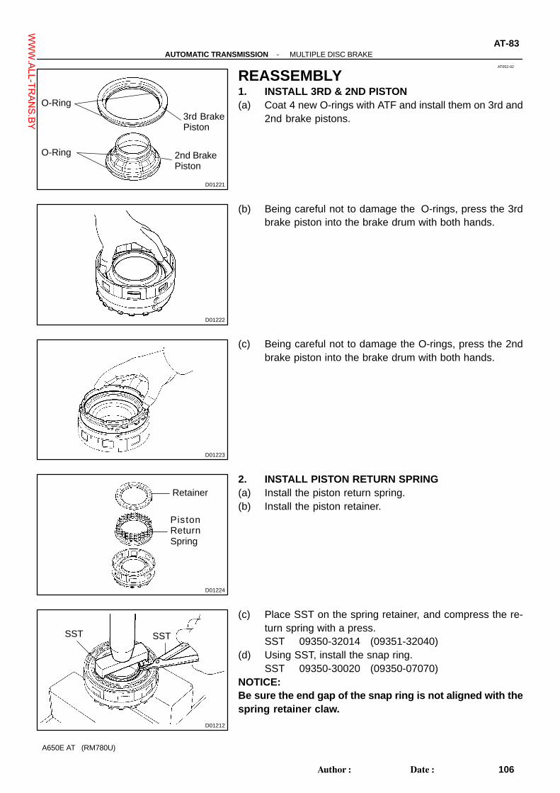
AT052-02
D01221
O-Ring
O-Ring
3rd BrakePiston
2nd BrakePiston
D01222
D01223
D01224
Retainer
PistonReturnSpring
D01212
SST SST
-AUTOMATIC TRANSMISSION MULTIPLE DISC BRAKEAT-83
106Author�: Date�:
A650E AT (RM780U)
REASSEMBLY1. INSTALL 3RD & 2ND PISTON(a) Coat 4 new O-rings with ATF and install them on 3rd and
2nd brake pistons.
(b) Being careful not to damage the O-rings, press the 3rdbrake piston into the brake drum with both hands.
(c) Being careful not to damage the O-rings, press the 2ndbrake piston into the brake drum with both hands.
2. INSTALL PISTON RETURN SPRING(a) Install the piston return spring.(b) Install the piston retainer.
(c) Place SST on the spring retainer, and compress the re-turn spring with a press.SST 09350-32014 (09351-32040)
(d) Using SST, install the snap ring.SST 09350-30020 (09350-07070)
NOTICE:Be sure the end gap of the snap ring is not aligned with thespring retainer claw.
WWW.ALL-TR
ANS.BY

D09448
PD
P
DP
P
D
P
D
Flange
PP
D01210
D01209
SST
AT-84-AUTOMATIC TRANSMISSION MULTIPLE DISC BRAKE
107Author�: Date�:
A650E AT (RM780U)
3. INSTALL PLATE, DISC AND FLANGE(a) Install the 7 plates and 4 discs.
Install in order: P = Plate, D = DiscP - D - P - P - D - P - P - D - P - P - D
(b) Install the flange, with the Facing its bevelled part downward.
HINT:Assemble the flange to the brake drum with facing a carvedmark on the flange upward.
(c) Using a screwdriver, install the snap ring.NOTICE:Be sure the end gap of the snap ring is not aligned with cut-out portion of the brake drum.
4. CHECK PISTON STROKE OF 3RD BRAKE PISTONUsing SST and a dial indicator, measure the 3rd piston strokewhile applying and releasing compressed air (392 kPa, 4kgf/cm2, 57 psi).
SST 09350-30020 (09350-06120)Piston stroke: 0.56 - 0.86 mm (0.022 - 0.036 in.)
NOTICE:Do not applying compressed air into the 2nd brake pistonhole.If the piston stroke is less than the limit of piston stroke, partsmay have been assembled incorrectly, so check and reas-semble again.If the clearance is non-standard, select another flange.HINT:There are 7 different flanges in thickness.Flange thickness: mm (in.)
No. Thickness No. Thickness
36 3.6 (0.142) 40 4.0 (0.157)
37 3.7 (0.146) 41 4.1 (0.161)
38 3.8 (0.150) 42 4.2 (0.165)
39 3.9 (0.154) - -
WWW.ALL-TR
ANS.BY

AT056-01
D01228
D01227
Bearing
Race
Center Planetary Gear
Center PlanetaryRing Gear
D01226
AT-88-AUTOMATIC TRANSMISSION CENTER PLANETARY GEAR
111Author�: Date�:
A650E AT (RM780U)
REASSEMBLY1. INSTALL CENTER PLANETARY RING GEAR(a) Install the center planetary ring gear to the intermediate
shaft.(b) Using a screwdriver, install the snap ring.
2. INSTALL CENTER PLANETARY GEAR(a) Install the bearing and 2 races to the center planetary ring
gear.(b) Install the center planetary gear.
(c) Assemble the snap ring to the front planetary ring gear.Nip the both ends of snap ring using needle nose pliersand install them to the output shaft with rear planetarygear so that the end gap of the snap ring comes on theindented part of the output shaft with rear planetary gear.
WWW.ALL-TR
ANS.BY

AT05A-01
D01232
D01439
Rear PlanetarySun Gear
AT-92-AUTOMATIC TRANSMISSION REAR PLANETARY GEAR
115Author�: Date�:
A650E AT (RM780U)
REASSEMBLY1. INSTALL RING GEAR FLANGE(a) Install the ring gear flange to the rear planetary ring gear.(b) Using a screwdriver, install the snap ring.
2. INSTALL REAR PLANETARY SUN GEAR
WWW.ALL-TR
ANS.BY

AT05E-02
D01242
O-Ring
No. 1 Brake Piston
ReactionSleeve
D01243
D01244
D01245
D01438
Snap Ring SST
-AUTOMATIC TRANSMISSION FIRST AND REVERSE BRAKEAT-97
120Author�: Date�:
A650E AT (RM780U)
REASSEMBLY1. INSTALL NO. 1 BRAKE PISTON(a) Coat 3 new O-rings with ATF.(b) Install the 2 O-rings on No. 1 brake piston.(c) Install the O-ring on the reaction sleeve.(d) Install the No. 1 brake piston to the reaction sleeve.
2. INSTALL REACTION SLEEVE AND NO. 1 BRAKE PIS-TON TO TRANSMISSION CASE
With the No. 1 brake piston underneath (the rear side), installthe brake reaction sleeve and No. 1 brake piston to the trans-mission case.NOTICE:Be careful not to damage the O-rings.
3. INSTALL NO. 2 BRAKE PISTON(a) Coat new O-ring with ATF.(b) Install the O-ring on No. 2 brake piston.(c) With the spring seat of the piston upwards (the front side),
place the piston in the transmission case.NOTICE:Be careful not to damage the O-ring.
(d) Place the piston return spring onto the No. 2 brake piston.
4. INSTALL PISTON RETURN SPRING(a) Place SST on the spring retainer and compress the return
spring.SST 09350-30020 (09350-07050)
(b) Using SST, install the snap ring.SST 09350-30020 (09350-07070)
WWW.ALL-TR
ANS.BY

D09449
PD
P
Flange
DPD
PD
PD
D01480
D01236
D01497
AT-98-AUTOMATIC TRANSMISSION FIRST AND REVERSE BRAKE
121Author�: Date�:
A650E AT (RM780U)
5. INSTALL PLATE, DISC AND FLANGE(a) Install the 5 plates, 5 discs and flange.
Install in order: P = Plate, D = DiscP - D - P - D - P - D - P - D - P - D
(b) Using a screwdriver, install the snap ring.NOTICE:Be sure the end gap of the snap ring is not aligned with thecutout portion of the case.
6. CHECK PACK OPERATION OF 1ST & REVERSEBRAKE
(a) Make sure the 1st & reverse brake pistons move smoothlywhen applying and releasing the compressed air (392kPa, 4 kgf/cm2, 57 psi) into the transmission case.
(b) Using feeler gauge, measure 1st & reverse brake packclearance between the snap ring and the flange.Pack clearance: 0.50 - 0.80 mm (0.020 - 0.031 in.)
If the piston stroke is less than limit of piston stroke, parts mayhave been assembled incorrectly, so check and reassembleagain.If the stroke is non-standard, select another plate.HINT:There are 13 different plates in thickness for the bottom plate.For the other plates, the thickness is 1.8 mm (0.071 in.).Plate thickness: mm (in.)
No. Thickness No. Thickness
01 1.8 (0.071) 08 2.5 (0.098)
02 1.9 (0.075) 09 2.6 (0.102)
03 2.0 (0.079) 10 2.7 (0.106)
04 2.1 (0.083) 11 2.8 (0.110)
05 2.2 (0.087) 12 2.9 (0.114)
06 2.3 (0.090) 13 3.0 (0.118)
07 2.4 (0.094) - -
WWW.ALL-TR
ANS.BY

FI1066
IN048-08
-INTRODUCTION REPAIR INSTRUCTIONSIN-3
3Author�: Date�:
A650E AT (RM780U)
REPAIR INSTRUCTIONSGENERAL INFORMATIONBASIC REPAIR HINT(a) Use fender, seat and floor covers to keep the vehicle
clean and prevent damage.(b) During disassembly, keep parts in the appropriate order
to facilitate reassembly.(c) Observe the following operations:
(1) Before performing electrical work, disconnect thenegative (-) terminal cable from the battery.
(2) If it is necessary to disconnect the battery for in-spection or repair, always disconnect the negative(-) terminal cable which is grounded to the vehiclebody.
(3) To prevent damage to the battery terminal, loosenthe cable nut and raise the cable straight up withouttwisting or prying it.
(4) Clean the battery terminals and cable ends with aclean shop rag. Do not scrape them with a file or oth-er abrasive objects.
(5) Install the cable ends to the battery terminals withthe nut loose, and tighten the nut after installation.Do not use a hammer to tap the cable ends onto theterminals.
(6) Be sure the cover for the positive (+) terminal isproperly in place.
(d) Check hose and wiring connectors to make sure that theyare secure and correct.
(e) Non-reusable parts(1) Always replace cotter pins, gaskets, O-rings and oil
seals etc. with new ones.(2) Non-reusable parts are indicated in the component
illustrations by the ”�” symbol.(f) Precoated parts
Precoated parts are bolts and nuts, etc. that are coatedwith a seal lock adhesive at the factory.(1) If a precoated part is retightened, or loosened or
caused to move in any way, it must be precoatedwith the specified adhesive.
(2) When reusing precoated parts, clean off the oldadhesive and dry with compressed air. Then applythe specified seal lock adhesive to the bolt, nut orthreads.
(3) Precoated parts are indicated in the component il-lustrations by the ”�” symbol.
(g) When necessary, use a sealer on gaskets to preventleaks.
WWW.ALL-TR
ANS.BY

IN0252
WRONG CORRECT
IN-4-INTRODUCTION REPAIR INSTRUCTIONS
4Author�: Date�:
A650E AT (RM780U)
(h) Carefully observe all specifications for bolt tighteningtorques. Always use a torque wrench.
(i) Use of special service tools (SST) and special service ma-terials (SSM) may be required, depending on the natureof the repair. Be sure to use SST and SSM where speci-fied and follow the proper work procedure. A list of SSTand SSM can be found in the preparation of AT section.
(j) To pull apart electrical connectors, pull the connector it-self, not the wires.
WWW.ALL-TR
ANS.BY

SS1HQ-01
SS-4-SERVICE SPECIFICATIONS AUTOMATIC TRANSMISSION
18Author�: Date�:
A650E AT (RM780U)
AUTOMATIC TRANSMISSIONSERVICE DATAOil Pump
Body clearance STD
Maximum
0.07 - 0.15 mm (0.0028 - 0.0059 in.)
0.3 mm (0.012 in.)
Tip clearance STD
Maximum
0.11 - 0.14 mm (0.0043 - 0.0055 in.)
0.3 mm (0.012 in.)
Side clearance STD
Maximum
0.02 - 0.04 mm (0.0008 - 0.0016 in.)
0.1 mm (0.004 in.)
Pump body bushing inside diameter Maximum 38.19 mm (1.5035 in.)
Stator shaft inside diameter (Front side) Maximum
(Rear side) Maximum
21.58 mm (0.8496 in.)
27.08 mm (1.0661 in.)
3rd Coast Brake
Piston rod stroke 2.0 - 3.0 mm (0.079 - 0.118 in.)
Piston rod length
77.65 mm (3.057 in.)
78.40 mm (3.087 in.)
79.15 mm (3.116 in.)
79.90 mm (3.146 in.)
80.65 mm (3.175 in.)
O/D Direct Clutch
Piston stroke 0.85 - 1.10 mm (0.033 - 0.043 in.)
Clutch return spring free length STD 15.8 mm (0.622 in.)
Clutch drum bushing inside diameter Maximum 27.11 mm (1.0673 in.)
O/D planetary gear bushing Maximum 11.27 mm (0.444 in.)
Planetary pinion gear thrust clearance STD
Maximum
0.2 - 0.6 mm (0.008 - 0.024 in.)
1.0 mm (0.039 in.)
Flange thickness No. 21
No. 20
No. 19
No. 18
No. 17
No. 16
No. 22
No. 23
3.1 mm (0.122 in.)
3.2 mm (0.126 in.)
3.3 mm (0.130 in.)
3.4 mm (0.134 in.)
3.5 mm (0.138 in.)
3.6 mm (0.142 in.)
3.7 mm (0.146 in.)
3.8 mm (0.151 in.)
O/D Brake
Piston return spring free length STD 17.82 mm (0.702 in.)
Piston stroke 1.32 - 1.62 mm (0.052 - 0.064 in.)
Flange thickness No. 77
No. 78
No. 79
No. 80
No. 81
No. 82
No. 83
3.3 mm (0.130 in.)
3.5 mm (0.138 in.)
3.6 mm (0.142 in.)
3.7 mm (0.146 in.)
3.8 mm (0.150 in.)
3.9 mm (0.154 in.)
4.0 mm (0.157 in.)
WWW.ALL-TR
ANS.BY

-SERVICE SPECIFICATIONS AUTOMATIC TRANSMISSIONSS-5
19Author�: Date�:
A650E AT (RM780U)
Direct Clutch
Piston stroke 0.40 - 0.70 mm (0.016 - 0.028 in.)
Clutch piston return spring free length STD 23.25 mm (0.915 in.)
Clutch drum bushing inside diameter Maximum 53.97 mm (2.1248 in.)
Flange thickness No. 53
No. 34
No. 35
No. 36
No. 37
No. 38
No. 39
No. 40
No. 41
3.3 mm (0.130 in.)
3.4 mm (0.134 in.)
3.5 mm (0.138 in.)
3.6 mm (0.142 in.)
3.7 mm (0.146 in.)
3.8 mm (0.150 in.)
3.9 mm (0.154 in.)
4.0 mm (0.157 in.)
4.1 mm (0.161 in.)
Forward Clutch
Piston stroke 0.60 - 0.90 mm (0.024 - 0.035 in.)
Clutch drum bushing inside diameter Maximum 20.08 mm (0.790 in.)
Flange thickness No. 61
No. 60
No. 45
No. 62
No. 44
No. 42
3.0 mm (0.118 in.)
3.2 mm (0.126 in.)
3.4 mm (0.134 in.)
3.6 mm (0.142 in.)
3.8 mm (0.150 in.)
4.0 mm (0.157 in.)
Multiple Disc Brake
Piston stroke 0.56 - 0.86 mm (0.022 - 0.034 in.)
Piston return spring free length STD 36.8 mm (1.449 in.)
Flange thickness No. 36
No. 37
No. 38
No. 39
No. 40
No. 41
No. 42
3.6 mm (0.142 in.)
3.7 mm (0.146 in.)
3.8 mm (0.150 in.)
3.9 mm (0.154 in.)
4.0 mm (0.157 in.)
4.1 mm (0.161 in.)
4.2 mm (0.165 in.)
Front Planetary Gear
Planetary pinion gear thrust clearance STD
Maximum
0.2 - 0.6 mm (0.008 - 0.024 in.)
1.0 mm (0.0394 in.)
Front & Center Planetary Sun Gear
Sun gear bushing inside diameter Maximum 24.79 mm (0.976 in.)
Center Planetary Gear
Planetary gear bushing inside diameter Maximum 41.31 mm (1.626 in.)
Planetary pinion gear thrust clearance STD
Maximum
0.2 - 0.6 mm (0.008 - 0.024 in.)
1.0 mm (0.039 in.)
2nd Brake
Flange thickness No. 21
No. 23
No. 25
No. 27
No. 29
No. 31
2.1 mm (0.083 in.)
2.3 mm (0.091 in.)
2.5 mm (0.098 in.)
2.7 mm (0.106 in.)
2.9 mm (0.114 in.)
3.1 mm (0.118 in.)
WWW.ALL-TR
ANS.BY

SS-6-SERVICE SPECIFICATIONS AUTOMATIC TRANSMISSION
20Author�: Date�:
A650E AT (RM780U)
Rear Planetary Gear
Planetary pinion gear thrust clearance STD
Maximum
0.2 - 0.6 mm (0.008 - 0.024 in.)
1.0 mm (0.0394 in.)
Rear planetary ring gear inside bushing Maximum 38.56 mm (1.518 in.)
1st & Reverse Brake
Pack clearance 0.5 - 0.8 mm (0.021 - 0.031 in.)
Piston return spring free length STD 20.0 mm (0.787 in.)
Plate thickness No. 01
No. 02
No. 03
No. 04
No. 05
No. 06
No. 07
No. 08
No. 09
No. 10
No. 11
No. 12
No. 13
1.8 mm (0.071 in.)
1.9 mm (0.075 in.)
2.0 mm (0.079 in.)
2.1 mm (0.083 in.)
2.2 mm (0.087 in.)
2.3 mm (0.090 in.)
2.4 mm (0.094 in.)
2.5 mm (0.098 in.)
2.6 mm (0.102 in.)
2.7 mm (0.106 in.)
2.8 mm (0.110 in.)
2.9 mm (0.114 in.)
3.0 mm (0.118 in.)
Output Shaft
Output shaft thrust play 1.63 - 2.89 mm (0.064 - 0.114 in.)
Output shaft inside bushing Maximum 20.08 mm (0.791 in.)
Extension Housing
Extension housing inside bushing Maximum 40.08 mm (1.5779 in.)
WWW.ALL-TR
ANS.BY

-SERVICE SPECIFICATIONS AUTOMATIC TRANSMISSIONSS-7
21Author�: Date�:
A650E AT (RM780U)
Valve Body Spring
SpringFree length/Outer diameter
mm (in.)Total No. of coils & (Color)
�Upper Valve Body
Lock-up relay valve 23.42 (0.922) / 5.86 (0.231) 12.25 (Red)
C-0 exhaust valve 24.25 (0.955) / 8.70 (0.343) 7.58 (Orange)
4-5 shift valve 25.50 (1.004) / 9.73 (0.383) 7.75 (Red)
Coast brake control valve 26.92 (1.060) / 8.70 (0.343) 10.53 (Green)
Secondary regulator valve 34.48 (1.357) / 9.22 (0.363) 13.5 (Red)
C-1 orifice control valve 37.13 (1.461) / 11.14 (0.439) 11.25 (White)
C-1 orifice control valve 21.50 (0.846) / 7.76 (0.306) 11.5 (None)
C-1 accumulator 78.16 (3.077) / 17.50 (0.689) 15.9 (Yellow)
Solenoid modulator valve 35.99 (1.417) / 8.30 (0.327) 13.8 (Light blue)
2-3 shift valve 25.50 (1.004) / 9.73 (0.383) 7.75 (Red)
B-3 control valve 26.05 (1.026) / 7.20 (0.283) 11.83 (Yellow)
B-3 control valve 19.79 (0.779) / 7.70 (0.303) 8.51 (Pink)
�Lower Valve No. 1 Body
3-4 shift valve 25.50 (1.004) / 9.73 (0.383) 7.75 (Red)
1-2 shift valve 25.50 (1.004) / 9.73 (0.383) 7.75 (Red)
B-2 release control valve 24.25 (0.955) / 8.70 (0.343) 7.58 (Orange)
Primary regulator valve 39.78 (1.566) / 18.88 (0.743) 6.65 (Light green)
Lock-up control valve 20.87 (0.822) / 5.55 (0.219) 11.15 (Yellow)
Cut back valve 22.60 (0.890) / 8.13 (0.320) 8.0 (None)
C-0 control relay valve 20.30 (0.799) / 6.10 (0.240) 12.75 (None)
Accumulator control valve 27.47 (1.081) / 8.85 (0.348) 11.59 (Light green)
Solenoid relay valve 32.11 (1.264) / 8.80 (0.346) 8.6 (Beige)
�Lower Valve No. 2 Valve
Reverse control valve 25.58 (1.007) / 8.64 (0.340) 8.75 (None)
Accumulator Spring
SpringFree length/Outer diameter
mm (in.)Color
B2 80.91 (3.185) / 19.97 (0.786) Pink & White
C2 Inside
Outside
41.00 (1.614) / 14.10 (0.555)
75.20 (2.961) / 20.10 (0.791)
Orange
White & Blue
B0 69.4 (2.732) / 16.25 (0.640) White
C0 65.00 (2.559) / 20.59 (0.811) None
WWW.ALL-TR
ANS.BY

SS-8-SERVICE SPECIFICATIONS AUTOMATIC TRANSMISSION
22Author�: Date�:
A650E AT (RM780U)
Valve Body Key
KeyHight
mm (in,)
Width
mm (in.)
Thickness
mm (in.)
�Upper Valve Body
Lock-up relay valve - - -
C-0 exhaust valve 8.5 (0.335) 5.0 (0.197) 3.2 (0.126)
4-5 shift valve 10.0 (0.394) 5.0 (0.197) 3.2 (0.126)
Coast brake control valve 15.0 (0.591) ø 5.0 (0.197) ø 5.0 (0.197)
Secondary regulator valve 10.0 (0.394) 5.0 (0.197) 3.2 (0.126)
C-1 orifice control valve 8.5 (0.335) 5.0 (0.197) 3.2 (0.126)
C-1 accumulator 36.5 (1.437) - 3.2 (0.126)
Solenoid modulator valve 21.0 (0.827) - 3.2 (0.126)
Check valve 10.0 (0.394) 5.0 (0.197) 3.2 (0.126)
2-3 shift valve 8.0 (0.315) 8.0 (0.315) 3.2 (0.126)
B-3 control valve 16.5 (0.650) 6.0 (0.236) 3.2 (0.126)
�Lower Valve No. 1 Body
3-4 shift valve 8.0 (0.315) 8.0 (0.315) 3.2 (0.126)
1-2 shift valve 8.0 (0.315) 8.0 (0.315) 3.2 (0.126)
B-2 release control valve 21.0 (0.827) - 3.2 (0.126)
Primary regulator valve - - 3.2 (0.126)
Lock-up control valve 19.0 (0.748) 5.0 (0.197) 3.2 (0.126)
Cut back valve 21.0 (0.827) - 3.2 (0.126)
C-0 control relay valve 8.5 (0.335) 5.0 (0.197) 3.2 (0.126)
Accumulator control valve 29.0 (1.142) 5.0 (0.197) 3.2 (0.126)
Solenoid relay valve 8.0 (0.315) 8.0 (0.315) 3.2 (0.126)
�Lower Valve No. 2 Body
Reverse control valve 8.5 (0.335) 5.0 (0.197) 3.2 (0.126)
WWW.ALL-TR
ANS.BY

SS0ZT-01
SS-2-SERVICE SPECIFICATIONS STANDARD BOLT
16Author�: Date�:
A650E AT (RM780U)
SPECIFIED TORQUE FOR STANDARD BOLTSSpecified torque
ClassDiameter
mm
Pitch
mmHexagon head bolt Hexagon flange boltClass
mm mmN·m kgf·cm ft·lbf N·m kgf·cm ft·lbf
4T
6
8
10
12
14
16
1
1.25
1.25
1.25
1.5
1.5
5
12.5
26
47
74
115
55
130
260
480
760
1,150
48 in.·lbf
9
19
35
55
83
6
14
29
53
84
-
60
145
290
540
850
-
52 in.·lbf
10
21
39
61
-
5T
6
8
10
12
14
16
1
1.25
1.25
1.25
1.5
1.5
6.5
15.5
32
59
91
140
65
160
330
600
930
1,400
56 in.·lbf
12
24
43
67
101
7.5
17.5
36
65
100
-
75
175
360
670
1,050
-
65 in.·lbf
13
26
48
76
-
6T
6
8
10
12
14
16
1
1.25
1.25
1.25
1.5
1.5
8
19
39
71
110
170
80
195
400
730
1,100
1,750
69 in.·lbf
14
29
53
80
127
9
21
44
80
125
-
90
210
440
810
1,250
-
78 in.·lbf
15
32
59
90
-
7T
6
8
10
12
14
16
1
1.25
1.25
1.25
1.5
1.5
10.5
25
52
95
145
230
110
260
530
970
1,500
2,300
8
19
38
70
108
166
12
28
58
105
165
-
120
290
590
1,050
1,700
-
9
21
43
76
123
-
8T
8
10
12
1.25
1.25
1.25
29
61
110
300
620
1,100
22
45
80
33
68
120
330
690
1,250
24
50
90
9T
8
10
12
1.25
1.25
1.25
34
70
125
340
710
1,300
25
51
94
37
78
140
380
790
1,450
27
57
105
10T
8
10
12
1.25
1.25
1.25
38
78
140
390
800
1,450
28
58
105
42
88
155
430
890
1,600
31
64
116
11T
8
10
12
1.25
1.25
1.25
42
87
155
430
890
1,600
31
64
116
47
97
175
480
990
1,800
35
72
130
WWW.ALL-TR
ANS.BY

PP3CJ-01
-PREPARATION AUTOMATIC TRANSMISSIONPP-1
9Author�: Date�:
A650E AT (RM780U)
AUTOMATIC TRANSMISSIONSST (Special Service Tools)
09032-00100 Oil Pan Seal Cutter
09223-15030 Oil Seal & Bearing Replacer
09240-00020 Wire Gauge Set
09308-10010 Oil Seal Puller
09325-20010 Transmission Oil Plug
09350-30020 TOYOTA Automatic Transmission
Tool Set
(09350-06120) No.2 Measure Terminal
(09350-07020) Oil Pump Puller
(09350-07040) No.2 Piston Spring Compressor
(09350-07050) No.3 Piston Spring Compressor
(09350-07060) No.1 Snap Ring Expander
(09350-07070) No.2 Snap Ring Expander
WWW.ALL-TR
ANS.BY
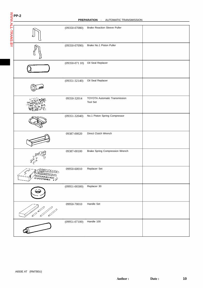
PP-2-PREPARATION AUTOMATIC TRANSMISSION
10Author�: Date�:
A650E AT (RM780U)
(09350-07080) Brake Reaction Sleeve Puller
(09350-07090) Brake No.1 Piston Puller
(09350-071 10) Oil Seal Replacer
(09351-32140) Oil Seal Replacer
09350-32014 TOYOTA Automatic Transmission
Tool Set
(09351-32040) No.1 Piston Spring Compressor
09387-00020 Direct Clutch Wrench
09387-00100 Brake Spring Compression Wrench
09950-60010 Replacer Set
(09951-00300) Replacer 30
09950-70010 Handle Set
(09951-07100) Handle 100
WWW.ALL-TR
ANS.BY

PP3CK-01
-PREPARATION AUTOMATIC TRANSMISSIONPP-3
11Author�: Date�:
A650E AT (RM780U)
RECOMMENDED TOOLS09031-00030 Pin Punch .
09905-00013 Snap Ring Pliers .
WWW.ALL-TR
ANS.BY

PP0S9-03
PP-4-PREPARATION AUTOMATIC TRANSMISSION
12Author�: Date�:
A650E AT (RM780U)
EQUIPMENTFeeler gauge Check major clearance.
Vernier calipers Check length of 2nd coast brake piston rod.
Calipers gauge Check inside diameter of the extension housing bushing.
Dial indicator or dial indicator with magnetic base Check piston stroke and play of the output shaft.
Dial indicator Check inside diameter of major bushing.
Straight edge Check side clearance of oil pump.
Torque wrench
Cylinder gauge Check inside diameter of the transmission case rear bushing.
WWW.ALL-TR
ANS.BY

PP0SA-03
-PREPARATION AUTOMATIC TRANSMISSIONPP-5
13Author�: Date�:
A650E AT (RM780U)
LUBRICANTItem Capacity Classification
Dry fill
Drain and refill
8.0 liters (8.5 US qts, 7.0 lmp qts)
2.4 liters (2.5 US qts, 2.1 lmp. qts)ATF Type T-lV or equivalent
WWW.ALL-TR
ANS.BY

PP3BR-01
PP-6-PREPARATION AUTOMATIC TRANSMISSION
14Author�: Date�:
A650E AT (RM780U)
SSM (Special Service Materials)08826-00090 Seal Packing 1281,
THREE BOND 1281 or equivalent
(FIPG)
Transmission case x Oil pan
08833-00070 Adhesive 1324,
THREE BOND 1324 or equivalent
Extension housing set bolt
08833-00080 Adhesive 1344
THREE BOND 1344
LOCTITE 242 or equivalent
Transmission case x Extension
housing
WWW.ALL-TR
ANS.BY

SS0F0-03
-SERVICE SPECIFICATIONS AUTOMATIC TRANSMISSIONSS-9
23Author�: Date�:
A650E AT (RM780U)
TORQUE SPECIFICATIONPart tightened N·m kgf·cm ft·lbf
Transmission housing x Transmission case 14 mm
17 mm
34
57
345
580
25
42
Extension housing x Transmission case 34 345 25
Breather pipe x Transmission housing 5.4 55 48 in.·lbf
Packing lock pawl bracket x Transmission case 7.4 75 65 in.·lbf
O/D support x Transmission case 25 260 19
Oil pump x Transmission case 21 215 16
Oil pump body x Stator shaft 10 100 7
Valve body x Transmission case 9.8 100 7
Upper valve body x Lower No. 1 valve body 6.4 65 56 in.·lbf
Lower valve No. 1 body x Lower valve No. 2 body 6.4 65 56 in.·lbf
Detent spring x Lower valve No. 1 body 9.8 100 7
Oil strainer x Valve body 9.8 100 7
Oil pan x Transmission case 7.4 75 65 in.·lbf
Drain plug 20 205 15
Vehicle speed sensor x Transmission case 5.4 55 48 in.·lbf
O/D direct clutch vehicle speed sensor x Transmission case 5.4 55 48 in.·lbf
Transmission wiring stopper plate x Transmission case 5.4 55 48 in.·lbf
ATF temperature sensor wire harness clamp set bolt 6.4 65 56 in.·lbf
Shift solenoid valve No. 1 and No. 3 x Lower valve No. 1 body 6.4 65 56 in.·lbf
Shift solenoid valve No. 2 and No. 4 x Lower valve No. 2 body 9.8 100 7
No. 1 Lock Plate x Lower valve No. 1 body 6.4 65 56 in.·lbf
No. 2 Lock Plate x lower valve No. 2 body 9.8 100 7
Union x Transmission case 29 300 22
Elbow x Transmission case 29 300 22
Park/Neutral position switch Bolt
Nut
13
6.9
130
70
9
61 in.·lbf
Control shaft lever 16 160 12
WWW.ALL-TR
ANS.BY