in the - gok lpg... · technical data • material: nbr gasket 1 1/4 acme f od 23 mm, id 13 mm, 3...
TRANSCRIPT


GOK offers again a complete range of products used between the tank and the consumerappliance if liquid and gaseous energy is concerned.
In the Picture price lists 2009 we have put new emphasis on the successful developmentof markets that become more and more difficult:
The clearly extended business area of tank data management that also allows solutions for • complex monitoring duties, e.g. in industrial applications.
A wide range of fittings for oil firing installations that is now already suitable for use with • biogenous components.
The comprehensive product range for LPG installations has again been extended, e.g. by • electronic monitoring appliances for autogas tank installations.
Enjoy studying the new catalogues.
The Picture price lists 2009 – Components / Solutions / Systems are available for:
CD: ”Our range at a glance - 2009”
All GOK Picture price lists as interactive files with gross prices, examples for applica-tions and animated safety devices.
Ask for the free new catalogues:
by e-mail: [email protected] or by telephone: +49 9332 404-0
Oil firing installations
LPG installations,including warming, burning, soldering
LPG tank equipment
Leisure time -caravan, camping, marine
Tank management
1
2
3
4
5
6
Picture price lists 2009
1
for overground and
underground LPG tanks 2
Filling 3 - 5Withdrawal 6 - 8Level indication 9 - 15Safety and monitoring 16 - 20Accessories 21 - 23Article list (in ascending order by part number) 24Abbreviations and units 25Notes 26 - 27Your contacts in the export department 28Index 29
in the product range:
Tank management LPG PRO 14 - 15
Tank equipment
Information given in this catalogue are subject to constructional modifi cations. For this reason, the indicated texts and dimensions are without obligation. The pictures show examples. Subject to typographical errors.
Upon publishing this catalogue, previous brochures are no longer applicable.
Table of contents

2
Tank equipment
for overground and
underground LPG tanks
A) Filling from page 3B) Withdrawal - liquid from page 6C) Withdrawal - vapour from page 7D) Level indication from page 9E) Safety and monitoring from page 16 Accessories from page 21
A B C D
E
3
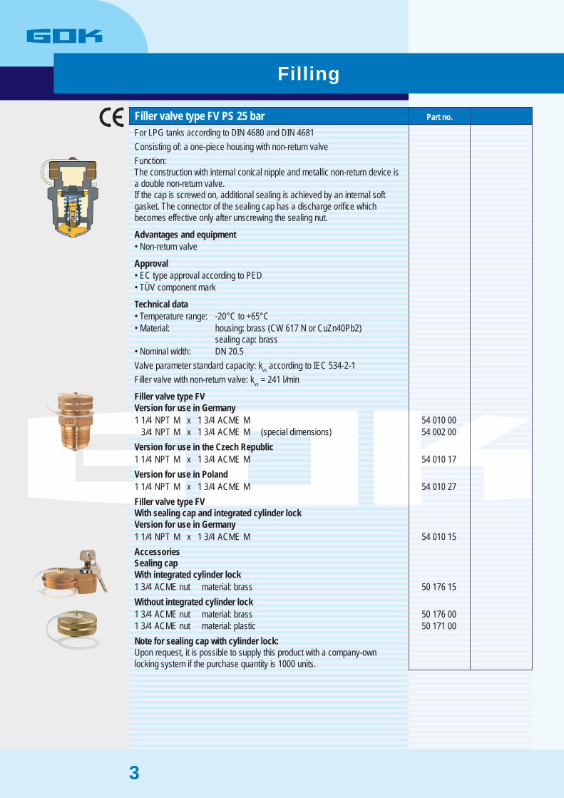
Filler valve type FV PS 25 bar Part no.
For LPG tanks according to DIN 4680 and DIN 4681Consisting of: a one-piece housing with non-return valveFunction:The construction with internal conical nipple and metallic non-return device isa double non-return valve.If the cap is screwed on, additional sealing is achieved by an internal softgasket. The connector of the sealing cap has a discharge orifi ce whichbecomes effective only after unscrewing the sealing nut.
Advantages and equipmentNon-return valve•
ApprovalEC type approval according to PED• TÜV component mark•
Technical dataTemperature range: -20°C to +65°C• Material: housing: brass (CW 617 N or CuZn40Pb2)• sealing cap: brassNominal width: DN 20.5•
Valve parameter standard capacity: kvs according to IEC 534-2-1Filler valve with non-return valve: kvs = 241 l/min
Filler valve type FVVersion for use in Germany1 1/4 NPT M x 1 3/4 ACME M 54 010 00
3/4 NPT M x 1 3/4 ACME M (special dimensions) 54 002 00 Version for use in the Czech Republic1 1/4 NPT M x 1 3/4 ACME M 54 010 17 Version for use in Poland1 1/4 NPT M x 1 3/4 ACME M 54 010 27 Filler valve type FVWith sealing cap and integrated cylinder lockVersion for use in Germany1 1/4 NPT M x 1 3/4 ACME M 54 010 15 AccessoriesSealing capWith integrated cylinder lock1 3/4 ACME nut material: brass 50 176 15 Without integrated cylinder lock1 3/4 ACME nut material: brass 50 176 00 1 3/4 ACME nut material: plastic 50 171 00 Note for sealing cap with cylinder lock:Upon request, it is possible to supply this product with a company-ownlocking system if the purchase quantity is 1000 units.
Filling
4
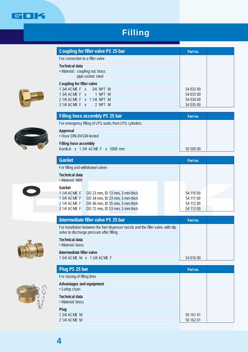
Coupling for fi ller valve PS 25 bar Part no.
For connection to a fi ller valve
Technical dataMaterial: coupling nut: brass• pipe socket: steel
Coupling for fi ller valve1 3/4 ACME F x 3/4 NPT M 54 032 00 1 3/4 ACME F x 1 NPT M 54 033 00 2 1/4 ACME F x 1 1/4 NPT M 54 034 00 3 1/4 ACME F x 2 NPT M 54 035 00
Filling hose assembly PS 25 bar Part no.
For emergency fi lling of LPG tanks from LPG cylinders
ApprovalHose DIN-DVGW-tested•
Filling hose assemblyKomb.A x 1 3/4 ACME F x 5000 mm 50 500 00
Gasket Part no.
For fi lling and withdrawal valves
Technical dataMaterial: NBR•
Gasket1 1/4 ACME F OD 23 mm, ID 13 mm, 3 mm thick 54 110 00 1 3/4 ACME F OD 34 mm, ID 23 mm, 3 mm thick 54 111 00 2 1/4 ACME F OD 46 mm, ID 35 mm, 3 mm thick 54 112 00 3 1/4 ACME F OD 72 mm, ID 53 mm, 3 mm thick 54 113 00
Intermediate fi ller valve PS 25 bar Part no.
For installation between the fuel dispenser nozzle and the fi ller valve, with dipvalve to discharge pressure after fi lling
Technical dataMaterial: brass•
Intermediate fi ller valve1 3/4 ACME M x 1 3/4 ACME F 54 016 00
Plug PS 25 bar Part no.
For closing of fi lling lines
Advantages and equipmentSafety chain•
Technical dataMaterial: brass•
Plug1 3/4 ACME M 50 161 01 2 1/4 ACME M 50 162 01
Filling
5
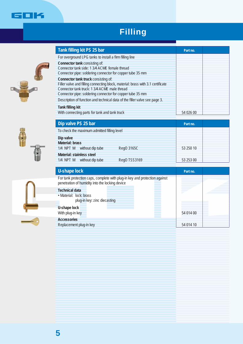
Tank fi lling kit PS 25 bar Part no.
For overground LPG tanks to install a fi rm fi lling lineConnector tank consisting of:Connector tank side: 1 3/4 ACME female threadConnector pipe: soldering connector for copper tube 35 mmConnector tank truck consisting of:Filler valve and fi lling connecting block, material: brass with 3.1 certifi cateConnector tank truck: 1 3/4 ACME male threadConnector pipe: soldering connector for copper tube 35 mmDescription of function and technical data of the fi ller valve see page 3.
Tank fi lling kitWith connecting parts for tank and tank truck 54 026 00
Dip valve PS 25 bar Part no.
To check the maximum admitted fi lling level
Dip valveMaterial: brass1/4 NPT M without dip tube RegO 3165C 53 250 10 Material: stainless steel1/4 NPT M without dip tube RegO TSS3169 53 253 00
U-shape lock Part no.
For tank protection caps, complete with plug-in key and protection againstpenetration of humidity into the locking device
Technical dataMaterial: lock: brass• plug-in key: zinc diecasting
U-shape lockWith plug-in key 54 014 00 AccessoriesReplacement plug-in key 54 014 10
Filling

6
Liquid withdrawal valve type FEV PS 25 bar Part no.
For LPG tanksAccording to German TRF 1996 for withdrawal of LPG in liquid phase fromthe tankThe construction of the valve with conical nipple, valve spindle with sealingand plug is designed as an angle valve operated manually.The plug at the outlet connector has a discharge orifi ce of 1.5 mm diameter which becomes operative only after loosening the plug.Additionally, the valve has a female thread 3/4” x 28 UN at the connector forthe LPG tank to assemble an immersion tube.Liquid withdrawal valve with excess fl ow valve:If the adjusted capacity is exceeded, an excess fl ow valve integrated in theliquid withdrawal valve closes at the side of the tank.The excess fl ow valve re-opens if the capacity falls below the response range.
Technical dataConnector: LPG tank: 3/4 NPT male thread• immersion tube: 3/4 x 28 UN female thread outlet: 3/4 NPT female threadTemperature range: -20°C to +65°C• Material housing: brass (CW 617 N or CuZn40Pb2)•
Valve parameter standard capacity kv = 139 l/h according to IEC 534-2-1Capacity response range of excess fl ow valve exceeding 70 kg/h LPG
Liquid withdrawal valve type FEVWith excess fl ow valveFor Germany 55 164 00 For Poland 55 164 47 Without excess fl ow valveFor Germany 55 160 10 For Poland 55 160 47 AccessoriesPlug 3/4 NPT M material: brass 54 250 00
Withdrawal
7
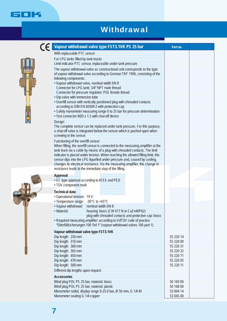
Vapour withdrawal valve type FST3.1VK PS 25 bar Part no.
With replaceable PTC sensorFor LPG tanks fi lled by tank trucksLimit indicator PTC sensor, replaceable under tank pressureThe vapour withdrawal valve as constructional unit corresponds to the type of vapour withdrawal valve according to German TRF 1996, consisting of the following components:
Vapour withdrawal valve, nominal width DN 8• Connector for LPG tank: 3/4” NPT male threadConnector for pressure regulator: POL female threadDip valve with immersion tube• Overfi ll sensor with vertically positioned plug with shrouded contacts• according to DIN EN 60309-2 with protection capSafety manometer measuring range 0 to 25 bar for pressure determination• Test connector M20 x 1.5 with shut-off device•
Design:The complete sensor can be replaced under tank pressure. For this purpose, a shut-off valve is integrated below the sensor which is pushed open whenscrewing in the sensor.Functioning of the overfi ll sensor:When fi lling, the overfi ll sensor is connected to the measuring amplifi er at thetank truck via a cable by means of a plug with shrouded contacts. The limitindicator is placed under tension. When reaching the allowed fi lling limit, thissensor dips into the LPG liquefi ed under pressure and, caused by cooling,changes its electrical resistance. Via the measuring amplifi er, this change inresistance leads to the immediate stop of the fi lling.
ApprovalEC type approval according to ATEX and PED• TÜV component mark•
Technical dataOperational tension: 19 V• Temperature range: -30°C to +65°C• Vapour withdrawal: nominal width DN 8• Material: housing: brass (CW 617 N or CuZn40Pb2)• plug with shrouded contacts and protective cap: brassRequired measuring amplifi er: according to VdTÜV code of practice• “Überfüllsicherungen 100 Teil 1” (vapour withdrawal valves 100 part 1)
Vapour withdrawal valve type FST3.1VKDip length 250 mm 55 220 14 Dip length 310 mm 55 220 00 Dip length 360 mm 55 220 31 Dip length 365 mm 55 220 32 Dip length 450 mm 55 220 71 Dip length 470 mm 55 220 05 Dip length 500 mm 55 220 11 Different dip lengths upon requestAccessoriesBlind plug POL PS 25 bar, material: brass 50 169 00 Blind plug POL PS 25 bar, material: plastic 50 168 00 Manometer radial, display range 0-25.0 bar, Ø 50 mm, G 1/4 M 53 004 14 Manometer sealing G 1/4 copper 53 045 00
Withdrawal
8
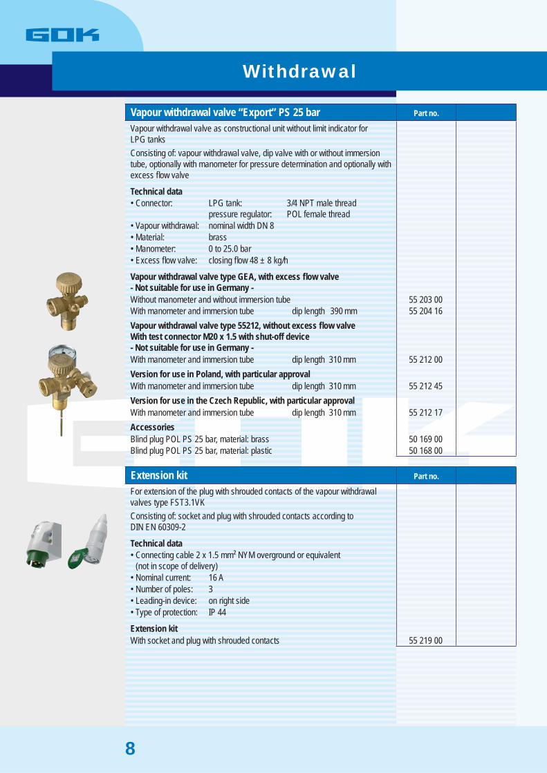
Vapour withdrawal valve “Export” PS 25 bar Part no.
Vapour withdrawal valve as constructional unit without limit indicator forLPG tanksConsisting of: vapour withdrawal valve, dip valve with or without immersiontube, optionally with manometer for pressure determination and optionally withexcess fl ow valve
Technical dataConnector: LPG tank: 3/4 NPT male thread• pressure regulator: POL female threadVapour withdrawal: nominal width DN 8• Material: brass• Manometer: 0 to 25.0 bar• Excess fl ow valve: closing fl ow 48 ± 8 kg/h•
Vapour withdrawal valve type GEA, with excess fl ow valve- Not suitable for use in Germany -Without manometer and without immersion tube 55 203 00 With manometer and immersion tube dip length 390 mm 55 204 16 Vapour withdrawal valve type 55212, without excess fl ow valveWith test connector M20 x 1.5 with shut-off device- Not suitable for use in Germany -With manometer and immersion tube dip length 310 mm 55 212 00 Version for use in Poland, with particular approvalWith manometer and immersion tube dip length 310 mm 55 212 45 Version for use in the Czech Republic, with particular approvalWith manometer and immersion tube dip length 310 mm 55 212 17 AccessoriesBlind plug POL PS 25 bar, material: brass 50 169 00 Blind plug POL PS 25 bar, material: plastic 50 168 00
Extension kit Part no.
For extension of the plug with shrouded contacts of the vapour withdrawalvalves type FST3.1VKConsisting of: socket and plug with shrouded contacts according toDIN EN 60309-2
Technical dataConnecting cable 2 x 1.5 mm² NYM overground or equivalent• (not in scope of delivery)Nominal current: 16 A• Number of poles: 3• Leading-in device: on right side• Type of protection: IP 44•
Extension kitWith socket and plug with shrouded contacts 55 219 00
Withdrawal

9
Level indication
Information on Rochester level gauges For LPG tanks
This type of level gauge meets the requirements of the German TRF 1996 orthe Pressure Equipment Directive. The indication of the contents of liquidphase is in percent by volume of the total volume.
The level gauge functions on the basis of the fl oat principle. Caused by liftingpower, a fl oat at the end of the bracket follows the LPG level in the tank.A counterbalance at the bracket guarantees a constant depth of immersion ofthe fl oat into the liquid phase. If the liquid level in the tank changes, themovement of the fl oat is transferred to a shaft by means of bevel gear drive.The shaft is protected by a tube. By means of a magnetic coupling at the endof the shaft, the reading is transferred to the outside scale.The separation between the contents of the tank and the scale is gastight.Therefore, the scale can be replaced under tank pressure. The admittedmaximum fi lling limit is shown on the scale as “MAX” and a marked redfi gure “85”%.A protection cap is part of the delivery scope.
Technical dataIndicating range of scale: 5 to 95%, with red fi gure at 85%• Material housing: aluminium• Temperature range: -20°C to +65°C•
The actual diameter of the LPG tank must correspond to the details on thediameter of the LPG tank on the housing. The centre of motion of the rodassembly for transmission must be designed according to the centre of the tank.
When placing an order, the following details are absolutely requested:1. Type description: “Junior”, “Senior” or “Magnetel”
2. Tank diameter
3. Type of tank: cylindrical tank or spherical tank
4. Type of installation: a) in the tank bottom b) sideways in the outer wall of the tank c) vertical from above d) at an angle in the tank bottom or in the outer wall
5. Additionally, to determine the dimensions of the gauge: Re. 4 a) shaft length “s” Re. 4 b) shaft length “s” Re. 4 c) distance between tank centre and bearing area (= shaft length “s”) Re. 4 d) angle between tank axis and nozzle of the liquid level indicator in degree or the vertical distance between the tank axis and the centre point of the bearing area of the liquid level gauge in millimetres; distance between centre of motion of liquid level indicator and its bearing area (= shaft length “s”). The centre of motion must be on this tank axis.
10
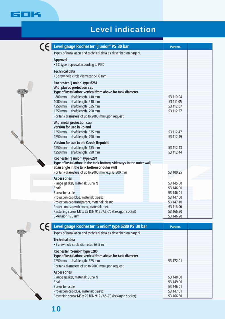
Level gauge Rochester “Junior” PS 30 bar Part no.
Types of installation and technical data as described on page 9.
ApprovalEC type approval according to PED•
Technical dataScrew-hole circle diameter: 51.6 mm•
Rochester “Junior” type 6281With plastic protection capType of installation: vertical from above for tank diameter
800 mm shaft length 410 mm 53 110 04 1000 mm shaft length 510 mm 53 111 05 1250 mm shaft length 635 mm 53 112 07 1250 mm shaft length 790 mm 53 112 27 For tank diameters of up to 2000 mm upon requestWith metal protection capVersion for use in Poland1250 mm shaft length 635 mm 53 112 47 1250 mm shaft length 790 mm 53 112 49 Version for use in the Czech Republic1250 mm shaft length 635 mm 53 112 43 1250 mm shaft length 790 mm 53 112 44 Rochester “Junior” type 6284Type of installation: in the tank bottom, sideways in the outer wall,at an angle in the tank bottom or outer wallFor tank diameters of up to 2000 mm, e.g. Ø 800 mm 53 100 25 AccessoriesFlange gasket, material: Buna N 53 145 00 Scale 53 146 00 Screw for scale 53 146 01 Protection cap blue, material: plastic 53 147 00 Protection cap transparent, material: plastic 53 147 10 Protection cap with cover, material: metal 53 116 00 Fastening screw M6 x 25 DIN 912 / AS-70 (hexagon socket) 53 166 20 Extension 175 mm 53 146 20
Level gauge Rochester “Senior” type 6280 PS 30 bar Part no.
Types of installation and technical data as described on page 9.
Technical dataScrew-hole circle diameter: 63.5 mm•
Rochester “Senior” type 6280Type of installation: vertical from above for tank diameter1250 mm shaft length 625 mm 53 172 01 For tank diameters of up to 2000 mm upon requestAccessoriesFlange gasket, material: Buna N 53 148 00 Scale 53 149 00 Screw for scale 53 146 01 Protection cap blue, material: plastic 53 147 01 Fastening screw M8 x 25 DIN 912 / AS-70 (hexagon socket) 53 166 30
Level indication

11
Level gauge Rochester “Magnetel” PS 25 bar Part no.
Big level gauge with 8“ scale for LPG tanks
Technical dataSpecial fl ange: “Magnetel”• Screw-hole circle diameter: 88.9 mm• Screw-hole diameter: 14.3 mm (8x)• Material fl ange: stainless steel• Temperature range: -20°C to +65°C• Operating material: LPG according to DIN 51622• Indicating range of scale: 5 to 95 % by volume (6360) or• 3 to 97 % by volumeFastening screws: M12 x 30 according to DIN 938 (8x)• Fastening nuts: M12 according to DIN 934 (8x)•
Rochester “Magnetel” type 6360-8 X or type 6360Type of installation: vertical from aboveFor tank diameters of up to 2900 mm 53 131 00 When inquiring for this product or sending an order, it is absolutely necessaryto indicate the diameter of the tank.Accessories8“ scale for type 6360-8 X and 6360 indicating range 5 to 95 % by volume 53 139 10 Flange gasket, material: Buna N 53 150 00
Level gauge Rochester “Twin Site” Junior PS 30 bar Part no.
Level gauge with pulse generator for mobile application in LPG tanks,e.g. in vehicles or fork lift trucks.Consisting of: level gauge with protection cap and pulse generator
Advantages and equipmentRemote reading, e.g. at the panel board of the vehicle•
Rochester “Twin Site” Junior type 6244Tank diameter 300 mm type of installation: sideways, 45° angle 53 153 00 Tank diameter 300 mm type of installation: sideways, 0° angle 53 155 00 Tank diameter 360 mm type of installation: sideways, 45° angle 53 152 00 Tank diameter 360 mm type of installation: sideways, 0° angle 53 154 00 Pulse generatorAMF for Twin Site 53 152 32
Level indication

12
Remote level gauge type IAF70 The remote level gauge type IAF70 shows the contents of liquid phase in an LPG storage tank in percent by volume. If the level falls below the adjustable threshold (5-30%), a visual and acoustic alarm is switched on at the indicator. In addition to this, it is possible to connect an external alarm via a potential-free relay.
The contents is shown on the display of the indicator and the transmitter. To determine the contents, a mechanical level gauge must be installed in the LPG storage tank. The maximum distance between indicator and transmitter is 180 metres.
ApprovalEC type approval according to ATEX •
Design IAF70The remote level gauge consists of the indicator and the transmitter S. The transmitter S is connected to the fl ange of the mechanical level gauge.Indicator and transmitter are connected by means of a cable.
IndicatorDesigned for wall mounting in a dry space, consisting of:electric power supply, two-digit level indication, ON-OFF switch, alarmluminous diode, programme key and a potential-free relay for external alarm.
Transmitter SDesigned for mounting on the mechanical level gauge of the tank,consisting of: magnetic fi eld sensor, evaluation electronics and two-digitlevel indication.
FunctionThe transmitter gets the required operation voltage from the indicator.
The magnetic fi eld sensor is sensitive to the line of the magnetic fi eld of the magnets situated at the shaft of the fl oat level gauge. The line of this magnetic fi eld determines the contents of the tank. The analogue signal produced by the magnetic fi eld sensor is converted into a digital signal by means of the electronics and transferred to the indicator. The indication is shown on a two-digit LCD display. The transmitter also has a two-digit LCD display for indication at the tank. A signalling threshold value can be adjusted at the indicator. If the tank contents falls below this level, a buzzer sounds, a luminous diode goes on and a relay is switched over.
Note for installation: The maximum cable length is 180 metres.
Technical dataIndicator
Connection to power supply: 230 V AC 50 Hz / 2.5 VA• Connection cable for transmitter: max. 180 m, 3 x 1.5 mm²• Temperature range: 0°C to +50°C• Type of protection housing: IP 30•
Transmitter SSupply: intrinsically safe 5.3 to 9.3 V• Temperature range: -40°C to +60°C• Interface: intrinsically safe, triple core• Type of protection housing: IP 68• Cable length: 6 metres•
Indicator IAF70
Transmitter S
Level indication
13
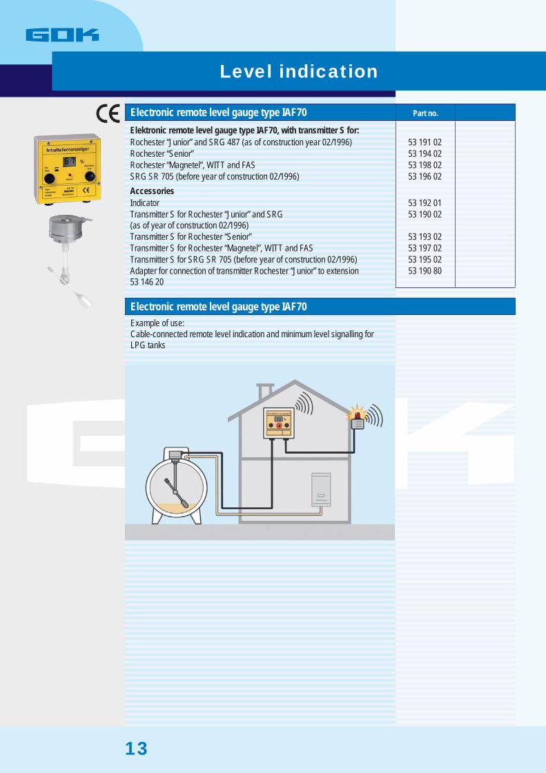
Electronic remote level gauge type IAF70 Part no.
Elektronic remote level gauge type IAF70, with transmitter S for:Rochester “Junior” and SRG 487 (as of construction year 02/1996) 53 191 02 Rochester “Senior” 53 194 02 Rochester “Magnetel”, WITT and FAS 53 198 02 SRG SR 705 (before year of construction 02/1996) 53 196 02 AccessoriesIndicator 53 192 01 Transmitter S for Rochester “Junior” and SRG(as of year of construction 02/1996)
53 190 02
Transmitter S for Rochester “Senior” 53 193 02 Transmitter S for Rochester “Magnetel”, WITT and FAS 53 197 02 Transmitter S for SRG SR 705 (before year of construction 02/1996) 53 195 02 Adapter for connection of transmitter Rochester “Junior” to extension53 146 20
53 190 80
Electronic remote level gauge type IAF70 Example of use: Cable-connected remote level indication and minimum level signalling for LPG tanks
Level indication

14
Tank management system LPG PRO System for tank contents determination, acquisition of operating states and remote transmission via the GSM radio network
ConstructionThe tank management system LPG PRO consists of a data transmitterwith integrated tank probe S. In addition, the data transmitter SmartBox 5 LPG has 2 event signalling entries that can be used, if required, as inlets for metres.The tank probe S is assembled to the connecting fl ange of the mechanicallevel indicator. The data transmitter and the tank probe are connected to each other by means of a cable.
Data transmitter SmartBox 5 LPGGSM data transmitter with integrated explosion-proof barrier
Function1 inlet for electronic tank level indicator• 2 inlets for event signalling, e.g. pump failure or alarm of a gas alarm• appliance
Technical dataSmartBox 5 LPG
Supply: 230 V AC 50 Hz• Inlets: 1 inlet for electronic tank level indicator•
2 inlets for gas metre, if required, or eventsType of protection: IP 30•
Tank probe SDesigned for assembly on the mechanical level indicator of the tank.Tension supply via the data transmitter SmartBox 5 LPG.
Consists of: magnetic fi eld coils, evaluation electronics and 2-digit levelindicator
Technical dataTank probe S
Supply: intrinsically safe 5.3 to 9.3 V• Temperature range: -40°C to +60°C• Interface: intrinsically safe, three-conductor• Type of protection housing: IP 68•
Connection of gas metres via reed contact Transmission of tank data via the GSM net and, as an option, connection
to internet data base www.smart-inspector.com (see catalogue tank management page 20).
Scope of delivery:GSM data ransmitter with status display and mounting accessories
Recommended accessories (see page 15):SIM card not included in the scope of delivery!• Internet data base www.smart-inspector.com• (see catalogue tank management page 20)
Optional accessories (see page 15):Additional antenna for SmartBox 4 and SmartBox 5•
Level indication

15
Tank management system LPG PRO Part no.
Tank management system LPG PRO, with tank probe S for:Rochester “Junior” and SRG 487 (as of construction year 02/1996) 28 701 00 Rochester “Senior” 28 702 00 Rochester “Magnetel”, WITT and FAS 28 703 00 SRG SR 705 (before construction year 02/1996) 28 704 00 AccessoriesData transmitter SmartBox 5 LPG 28 570 00 Additional antenna for SmartBox 4 and SmartBox 5 28 858 00 Costs for system hosting, administration, data saving and preparation of tank data - each month
58 700 00
Tank probe S for Rochester “Junior” and SRG(as of construction year 02/1996)
53 190 02
Tank probe S for Rochester “Senior” 53 193 02 Tank probe S for Rochester “Magnetel”, WITT and FAS 53 197 02 Tank probe S for SRG SR 705 (before construction year 02/1996) 53 195 02
Tank management system LPG PRO Example of use: Contents determination and remote data transmission by GSM
Level indication
16
Safety valve PS 25 bar Part no.
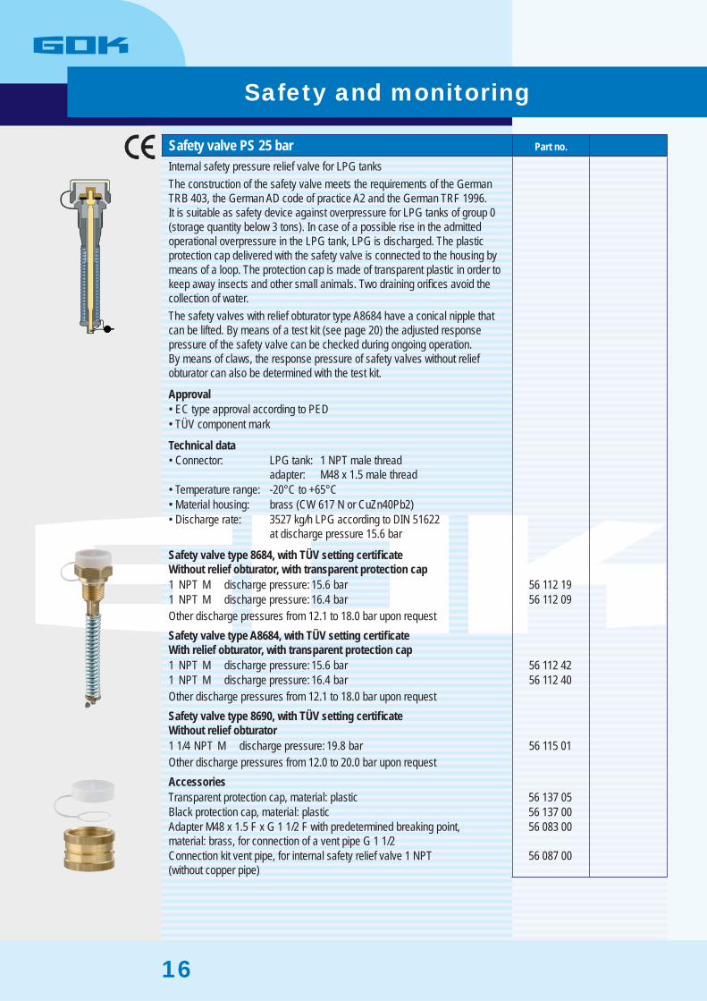
Internal safety pressure relief valve for LPG tanksThe construction of the safety valve meets the requirements of the GermanTRB 403, the German AD code of practice A2 and the German TRF 1996.It is suitable as safety device against overpressure for LPG tanks of group 0(storage quantity below 3 tons). In case of a possible rise in the admittedoperational overpressure in the LPG tank, LPG is discharged. The plasticprotection cap delivered with the safety valve is connected to the housing bymeans of a loop. The protection cap is made of transparent plastic in order tokeep away insects and other small animals. Two draining orifi ces avoid thecollection of water.The safety valves with relief obturator type A8684 have a conical nipple thatcan be lifted. By means of a test kit (see page 20) the adjusted responsepressure of the safety valve can be checked during ongoing operation.By means of claws, the response pressure of safety valves without reliefobturator can also be determined with the test kit.
ApprovalEC type approval according to PED• TÜV component mark•
Technical dataConnector: LPG tank: 1 NPT male thread• adapter: M48 x 1.5 male threadTemperature range: -20°C to +65°C• Material housing: brass (CW 617 N or CuZn40Pb2)• Discharge rate: 3527 kg/h LPG according to DIN 51622• at discharge pressure 15.6 bar
Safety valve type 8684, with TÜV setting certifi cate Without relief obturator, with transparent protection cap1 NPT M discharge pressure: 15.6 bar 56 112 19 1 NPT M discharge pressure: 16.4 bar 56 112 09 Other discharge pressures from 12.1 to 18.0 bar upon requestSafety valve type A8684, with TÜV setting certifi cateWith relief obturator, with transparent protection cap1 NPT M discharge pressure: 15.6 bar 56 112 42 1 NPT M discharge pressure: 16.4 bar 56 112 40 Other discharge pressures from 12.1 to 18.0 bar upon requestSafety valve type 8690, with TÜV setting certifi cateWithout relief obturator1 1/4 NPT M discharge pressure: 19.8 bar 56 115 01 Other discharge pressures from 12.0 to 20.0 bar upon requestAccessoriesTransparent protection cap, material: plastic 56 137 05 Black protection cap, material: plastic 56 137 00 Adapter M48 x 1.5 F x G 1 1/2 F with predetermined breaking point,material: brass, for connection of a vent pipe G 1 1/2
56 083 00
Connection kit vent pipe, for internal safety relief valve 1 NPT(without copper pipe)
56 087 00
Safety and monitoring
17
Replaceable safety valve PS 25 bar Part no.
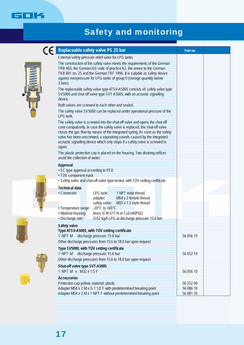
External safety pressure relief valve for LPG tanksThe construction of the safety valve meets the requirements of the GermanTRB 403, the German AD code of practice A2, the annex to the GermanTRB 801 no. 25 and the German TRF 1996. It is suitable as safety deviceagainst overpressure for LPG tanks of group 0 (storage quantity below3 tons).The replaceable safety valve type ATSV-A5005 consists of: safety valve typeSV5000 and shut-off valve type SVT-A5005, with an acoustic signallingdevice.Both valves are screwed to each other and sealed.The safety valve SV5000 can be replaced under operational pressure of theLPG tank.The safety valve is screwed into the shut-off valve and opens the shut-offcone compulsorily. In case the safety valve is replaced, the shut-off valvecloses the gas fl ow by means of the integrated spring. As soon as the safetyvalve has been unscrewed, a squeaking sounds caused by the integratedacoustic signalling device which only stops if a safety valve is screwed inagain.The plastic protection cap is placed on the housing. Two draining orifi cesavoid the collection of water.
ApprovalEC type approval according to PED• TÜV component mark• Safety valve and shut-off valve type-tested, with TÜV setting certifi cate•
Technical dataConnector: LPG tank: 1 NPT male thread• adapter: M54 x 2 female thread safety valve: M32 x 1.5 male threadTemperature range: -20°C to +65°C• Material housing: brass (CW 617 N or CuZn40Pb2)• Discharge rate: 3152 kg/h LPG at discharge pressure 15.6 bar•
Safety valveType ATSV-A5005, with TÜV setting certifi cate1 NPT M discharge pressure: 15.6 bar 56 056 19 Other discharge pressures from 15.6 to 18.0 bar upon requestType SV5000, with TÜV setting certifi cate1 NPT M discharge pressure: 15.6 bar 56 052 19 Other discharge pressures from 15.6 to 18.0 bar upon requestShut-off valve type SVT-A50051 NPT M x M32 x 1.5 F 56 056 10 AccessoriesProtection cap yellow, material: plastic 56 252 90 Adapter M54 x 2 M x G 1 1/2 F with predetermined breaking point 56 086 10 Adapter M54 x 2 M x 1 NPT F without predetermined breaking point 56 081 10
Safety and monitoring

18
Replaceable safety valve ATSV5000 PS 25 bar Part no.
External safety pressure relief valve 1“ NPT for LPG tanksThe replaceable safety valve type ATSV5000 consists of:safety valve type SV5000 with fi tted protection cap and shut-off valvetype SVT5000.Both valves are screwed to each other and sealed.The safety valve SV5000 can be replaced under operational pressure ofthe LPG tank.The safety valve is screwed into the shut-off valve and opens the shut-offcone compulsorily. In case the safety valve is replaced, the shut-off valve closes the gas fl ow by means of the integrated spring.
ApprovalEC type approval according to PED (for safety valve)• Safety valve type-approved, with TÜV setting certifi cate•
Technical dataConnector: LPG tank: 1 or 1 1/4” NPT male thread• adapter: M54 x 2 female thread safety valve / shut-off valve: M32 x 1.5 male threadTemperature range: -20°C to +65°C• Material housing: brass (CW 617 N or CuZn40Pb2)• Discharge rate: 3152 kg/h LPG at discharge pressure 15.6 bar•
Safety valve type ATSV5000, with TÜV setting certifi cate1 NPT M discharge pressure: 15.6 bar 56 050 19 1 1/4 NPT M discharge pressure: 15.6 bar 56 055 19 Other discharge pressures from 15.6 to 18.0 bar upon requestSafety valve type ATSV5000, with GOK setting certifi cateFor use in Poland1 NPT M discharge pressure: 15.6 bar 56 050 20 1 1/4 NPT M discharge pressure: 15.6 bar 56 055 20 Safety valve type ATSV5000 with TÜV setting certifi cateFor use in the Czech Republic1 NPT M discharge pressure: 15.6 bar 56 050 17 1 1/4 NPT M discharge pressure: 15.6 bar 56 055 17 ComponentsSafety valve type SV50001 NPT M discharge pressure: 15.6 bar 56 052 19 Other discharge pressures upon requestShut-off valve type SVT50001 NPT M x M32 x 1.5 F 56 051 00 1 1/4 NPT M x M32 x 1.5 F 56 051 10 AccessoriesProtection cap yellow, material: plastic 56 252 90 Adapter M54 x 2 M x G 1 1/2 F with predetermined breaking point 56 086 10 Adapter M54 x 2 M x 1 NPT F without predetermined breaking point 56 081 10
Safety and monitoring
19
Safety valve PS 25 bar Part no.
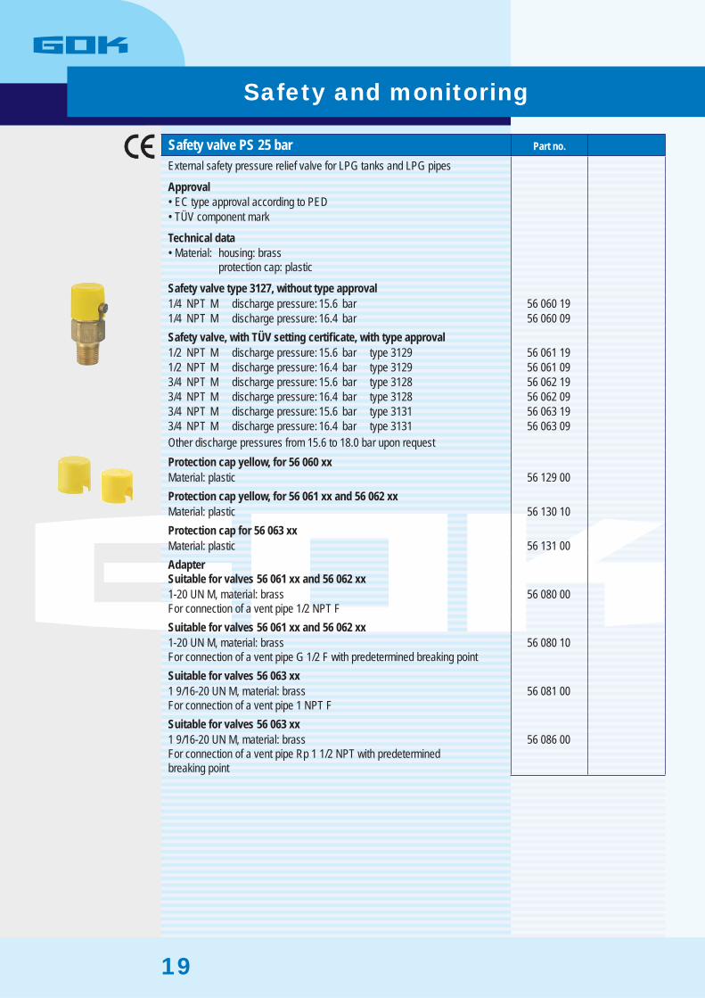
External safety pressure relief valve for LPG tanks and LPG pipes
ApprovalEC type approval according to PED• TÜV component mark•
Technical dataMaterial: housing: brass• protection cap: plastic
Safety valve type 3127, without type approval1/4 NPT M discharge pressure: 15.6 bar 56 060 19 1/4 NPT M discharge pressure: 16.4 bar 56 060 09 Safety valve, with TÜV setting certifi cate, with type approval1/2 NPT M discharge pressure: 15.6 bar type 3129 56 061 19 1/2 NPT M discharge pressure: 16.4 bar type 3129 56 061 09 3/4 NPT M discharge pressure: 15.6 bar type 3128 56 062 19 3/4 NPT M discharge pressure: 16.4 bar type 3128 56 062 09 3/4 NPT M discharge pressure: 15.6 bar type 3131 56 063 19 3/4 NPT M discharge pressure: 16.4 bar type 3131 56 063 09 Other discharge pressures from 15.6 to 18.0 bar upon requestProtection cap yellow, for 56 060 xxMaterial: plastic 56 129 00 Protection cap yellow, for 56 061 xx and 56 062 xxMaterial: plastic 56 130 10 Protection cap for 56 063 xxMaterial: plastic 56 131 00 AdapterSuitable for valves 56 061 xx and 56 062 xx1-20 UN M, material: brassFor connection of a vent pipe 1/2 NPT F
56 080 00
Suitable for valves 56 061 xx and 56 062 xx1-20 UN M, material: brassFor connection of a vent pipe G 1/2 F with predetermined breaking point
56 080 10
Suitable for valves 56 063 xx1 9/16-20 UN M, material: brassFor connection of a vent pipe 1 NPT F
56 081 00
Suitable for valves 56 063 xx1 9/16-20 UN M, material: brassFor connection of a vent pipe Rp 1 1/2 NPT with predeterminedbreaking point
56 086 00
Safety and monitoring
20
Test kit for internal safety valve Part no.
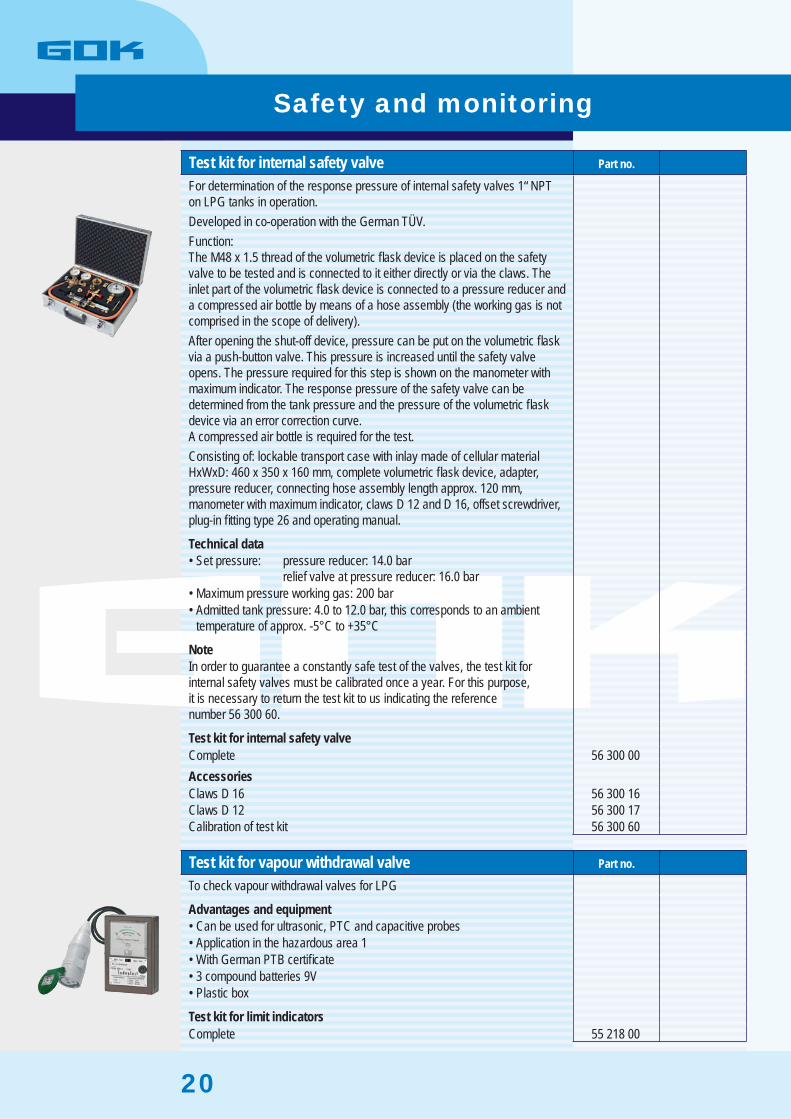
For determination of the response pressure of internal safety valves 1“ NPT on LPG tanks in operation.Developed in co-operation with the German TÜV.Function:The M48 x 1.5 thread of the volumetric fl ask device is placed on the safety valve to be tested and is connected to it either directly or via the claws. The inlet part of the volumetric fl ask device is connected to a pressure reducer anda compressed air bottle by means of a hose assembly (the working gas is notcomprised in the scope of delivery).After opening the shut-off device, pressure can be put on the volumetric fl ask via a push-button valve. This pressure is increased until the safety valveopens. The pressure required for this step is shown on the manometer with maximum indicator. The response pressure of the safety valve can be determined from the tank pressure and the pressure of the volumetric fl ask device via an error correction curve.A compressed air bottle is required for the test.Consisting of: lockable transport case with inlay made of cellular materialHxWxD: 460 x 350 x 160 mm, complete volumetric fl ask device, adapter,pressure reducer, connecting hose assembly length approx. 120 mm,manometer with maximum indicator, claws D 12 and D 16, offset screwdriver,plug-in fi tting type 26 and operating manual.
Technical dataSet pressure: pressure reducer: 14.0 bar• relief valve at pressure reducer: 16.0 barMaximum pressure working gas: 200 bar• Admitted tank pressure: 4.0 to 12.0 bar, this corresponds to an ambient • temperature of approx. -5°C to +35°C
NoteIn order to guarantee a constantly safe test of the valves, the test kit forinternal safety valves must be calibrated once a year. For this purpose,it is necessary to return the test kit to us indicating the referencenumber 56 300 60.
Test kit for internal safety valveComplete 56 300 00 AccessoriesClaws D 16 56 300 16 Claws D 12 56 300 17 Calibration of test kit 56 300 60
Test kit for vapour withdrawal valve Part no.
To check vapour withdrawal valves for LPG
Advantages and equipmentCan be used for ultrasonic, PTC and capacitive probes• Application in the hazardous area 1• With German PTB certifi cate• 3 compound batteries 9V• Plastic box•
Test kit for limit indicatorsComplete 55 218 00
Safety and monitoring
21
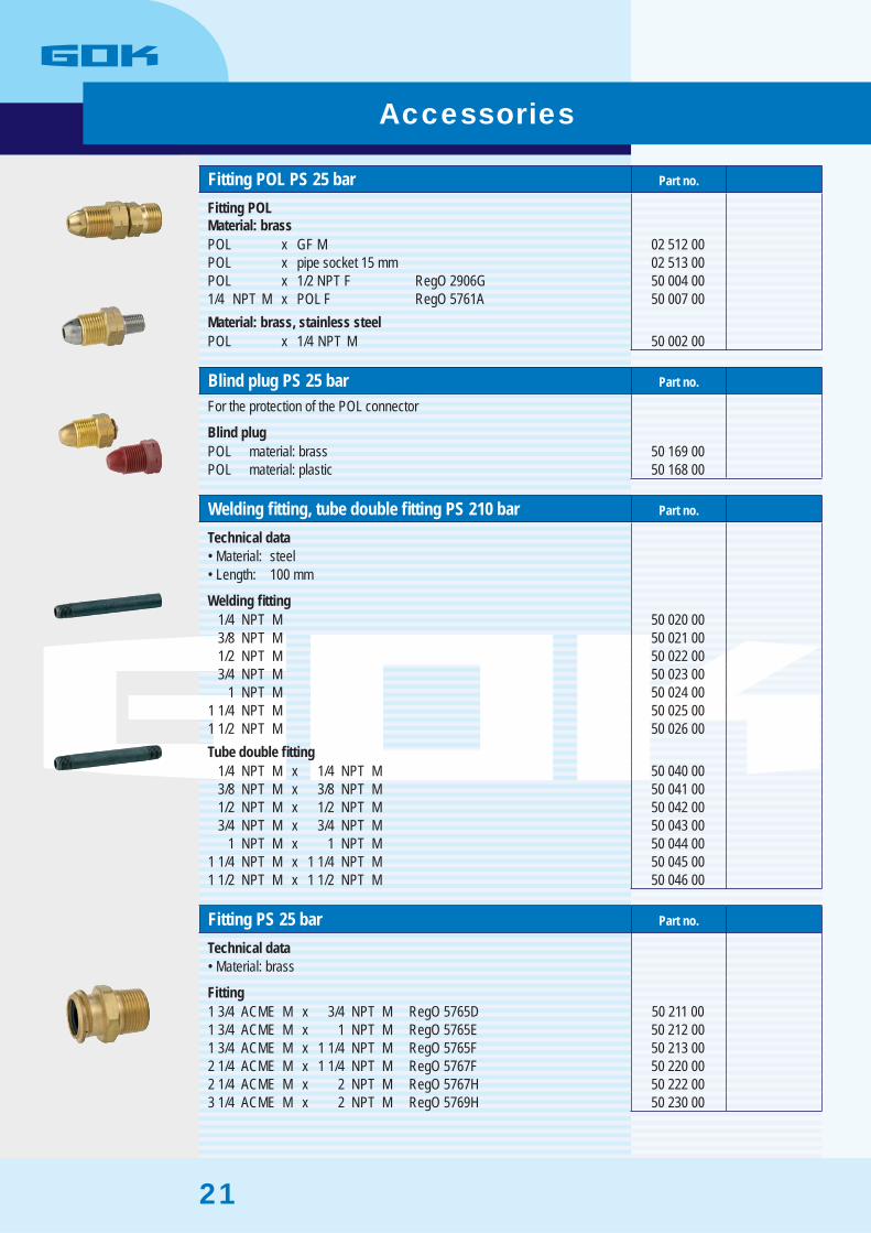
Fitting POL PS 25 bar Part no.
Fitting POLMaterial: brassPOL x GF M 02 512 00 POL x pipe socket 15 mm 02 513 00 POL x 1/2 NPT F RegO 2906G 50 004 00 1/4 NPT M x POL F RegO 5761A 50 007 00 Material: brass, stainless steelPOL x 1/4 NPT M 50 002 00
Blind plug PS 25 bar Part no.
For the protection of the POL connector
Blind plugPOL material: brass 50 169 00 POL material: plastic 50 168 00
Welding fi tting, tube double fi tting PS 210 bar Part no.
Technical dataMaterial: steel• Length: 100 mm•
Welding fi tting1/4 NPT M 50 020 00 3/8 NPT M 50 021 00 1/2 NPT M 50 022 00 3/4 NPT M 50 023 00
1 NPT M 50 024 00 1 1/4 NPT M 50 025 00 1 1/2 NPT M 50 026 00 Tube double fi tting
1/4 NPT M x 1/4 NPT M 50 040 00 3/8 NPT M x 3/8 NPT M 50 041 00 1/2 NPT M x 1/2 NPT M 50 042 00 3/4 NPT M x 3/4 NPT M 50 043 00
1 NPT M x 1 NPT M 50 044 00 1 1/4 NPT M x 1 1/4 NPT M 50 045 00 1 1/2 NPT M x 1 1/2 NPT M 50 046 00
Fitting PS 25 bar Part no.
Technical dataMaterial: brass•
Fitting1 3/4 ACME M x 3/4 NPT M RegO 5765D 50 211 00 1 3/4 ACME M x 1 NPT M RegO 5765E 50 212 00 1 3/4 ACME M x 1 1/4 NPT M RegO 5765F 50 213 00 2 1/4 ACME M x 1 1/4 NPT M RegO 5767F 50 220 00 2 1/4 ACME M x 2 NPT M RegO 5767H 50 222 00 3 1/4 ACME M x 2 NPT M RegO 5769H 50 230 00
Accessories

22
Bushing PS 210 bar Part no.
Technical dataMaterial: steel•
Half bushing1/4 NPT F length: 17 mm 50 060 00 3/8 NPT F length: 19 mm 50 061 00 1/2 NPT F length: 24 mm 50 062 00 3/4 NPT F length: 25 mm 50 063 00
1 NPT F length: 30 mm 50 064 00 1 1/4 NPT F length: 33 mm 50 065 00 1 1/2 NPT F length: 40 mm 50 066 00 Bushing
1/4 NPT F x 1/4 NPT F length: 35 mm 50 080 00 3/8 NPT F x 3/8 NPT F length: 38 mm 50 081 00 1/2 NPT F x 1/2 NPT F length: 48 mm 50 082 00 3/4 NPT F x 3/4 NPT F length: 51 mm 50 083 00
1 NPT F x 1 NPT F length: 60 mm 50 084 00 1 1/4 NPT F x 1 1/4 NPT F length: 67 mm 50 085 00 1 1/2 NPT F x 1 1/2 NPT F length: 79 mm 50 086 00
Hexagon plug PS 210 bar Part no.
Technical dataMaterial: steel•
Hexagon plug1/4 NPT M length: 23 mm 50 120 00 3/8 NPT M length: 26 mm 50 121 00 1/2 NPT M length: 27 mm 50 122 00 3/4 NPT M length: 34 mm 50 123 00
1 NPT M length: 35 mm 50 124 00 1 1/4 NPT M length: 39 mm 50 125 00 1 1/2 NPT M length: 41 mm 50 126 00
Reducer PS 210 bar Part no.
Technical dataMaterial: steel•
Reducer3/8 NPT M x 1/4 NPT F length: 19 mm 50 140 00 1/2 NPT M x 1/4 NPT F length: 23 mm 50 141 00 3/4 NPT M x 1/4 NPT F length: 25 mm 50 142 00 3/4 NPT M x 1/2 NPT F length: 25 mm 50 143 00
1 NPT M x 3/4 NPT F length: 27 mm 50 145 00 1 1/4 NPT M x 3/4 NPT F length: 31 mm 50 147 00 1 1/4 NPT M x 1 NPT F length: 31 mm 50 148 00
2 NPT M x 1 1/4 NPT F length: 37 mm 50 156 00
Accessories
23
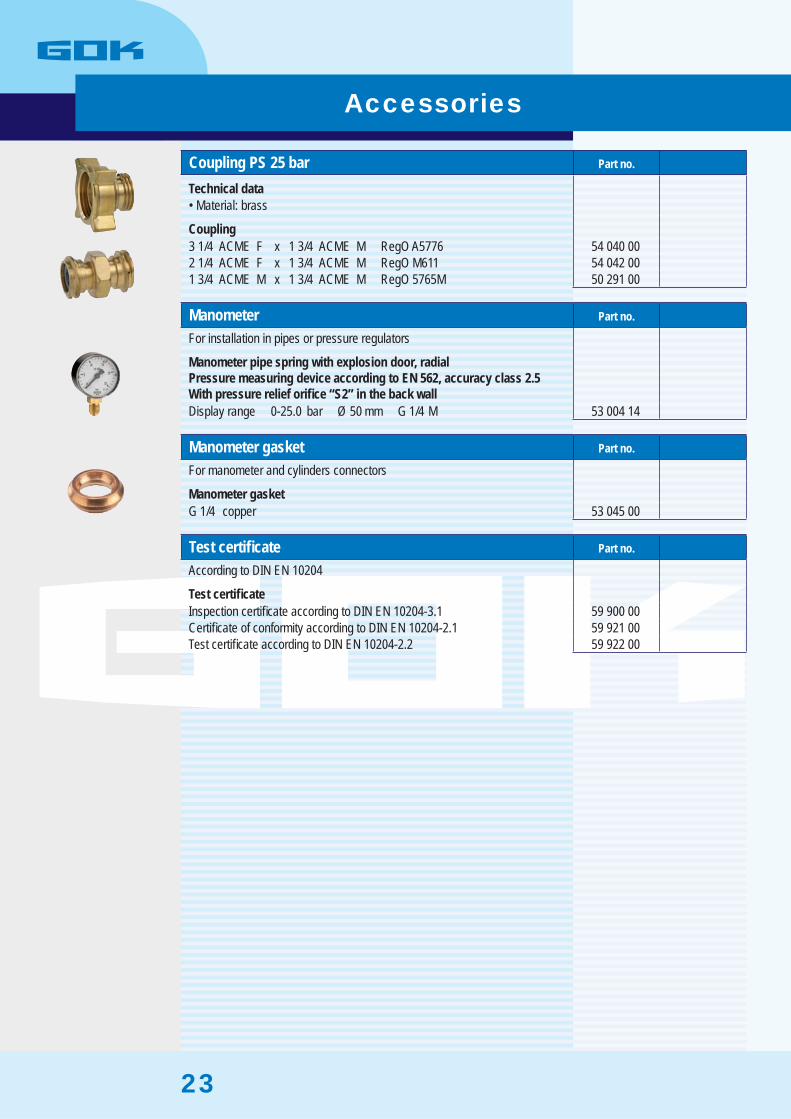
Coupling PS 25 bar Part no.
Technical dataMaterial: brass•
Coupling3 1/4 ACME F x 1 3/4 ACME M RegO A5776 54 040 00 2 1/4 ACME F x 1 3/4 ACME M RegO M611 54 042 00 1 3/4 ACME M x 1 3/4 ACME M RegO 5765M 50 291 00
Manometer Part no.
For installation in pipes or pressure regulators
Manometer pipe spring with explosion door, radial Pressure measuring device according to EN 562, accuracy class 2.5With pressure relief orifi ce “S2” in the back wallDisplay range 0-25.0 bar Ø 50 mm G 1/4 M 53 004 14
Manometer gasket Part no.
For manometer and cylinders connectors
Manometer gasketG 1/4 copper 53 045 00
Test certifi cate Part no.
According to DIN EN 10204
Test certifi cateInspection certifi cate according to DIN EN 10204-3.1 59 900 00 Certifi cate of conformity according to DIN EN 10204-2.1 59 921 00 Test certifi cate according to DIN EN 10204-2.2 59 922 00
Accessories

24
Part no. Page Part no. Page Part no. Page Part no. Page
02 512 00 2102 513 00 2128 570 00 1528 701 00 1528 702 00 1528 703 00 1528 704 00 1528 858 00 1550 002 00 2150 004 00 2150 007 00 2150 020 00 2150 021 00 2150 022 00 2150 023 00 2150 024 00 2150 025 00 2150 026 00 2150 040 00 2150 041 00 2150 042 00 2150 043 00 2150 044 00 2150 045 00 2150 046 00 2150 060 00 2250 061 00 2250 062 00 2250 063 00 2250 064 00 2250 065 00 2250 066 00 2250 080 00 2250 081 00 2250 082 00 2250 083 00 2250 084 00 2250 085 00 2250 086 00 2250 120 00 2250 121 00 2250 122 00 2250 123 00 2250 124 00 2250 125 00 2250 126 00 2250 140 00 2250 141 00 2250 142 00 2250 143 00 2250 145 00 2250 147 00 2250 148 00 22
50 156 00 2250 161 01 450 162 01 450 168 00 2150 169 00 2150 171 00 350 176 00 350 176 15 350 211 00 2150 212 00 2150 213 00 2150 220 00 2150 222 00 2150 230 00 2150 291 00 2350 500 00 453 004 14 2353 045 00 2353 100 25 1053 110 04 1053 111 05 1053 112 07 1053 112 27 1053 112 43 1053 112 44 1053 112 47 1053 112 49 1053 116 00 1053 131 00 1153 139 10 1153 145 00 1053 146 00 1053 146 01 1053 146 20 1053 147 00 1053 147 01 1053 147 10 1053 148 00 1053 149 00 1053 150 00 1153 152 00 1153 152 32 1153 153 00 1153 154 00 1153 155 00 1153 166 20 1053 166 30 1053 172 01 1053 190 02 13, 1553 190 80 1353 191 02 1353 192 01 1353 193 02 13, 15
53 194 02 1353 195 02 13, 1553 196 02 1353 197 02 13, 1553 198 02 1353 250 10 553 253 00 554 002 00 354 010 00 354 010 15 354 010 17 354 010 27 354 014 00 554 014 10 554 016 00 454 026 00 554 032 00 454 033 00 454 034 00 454 035 00 454 040 00 2354 042 00 2354 110 00 454 111 00 454 112 00 454 113 00 454 250 00 655 160 10 655 160 47 655 164 00 655 164 47 655 203 00 855 204 16 855 212 00 855 212 17 855 212 45 855 218 00 2055 219 00 855 220 00 755 220 05 755 220 11 755 220 14 755 220 31 755 220 32 755 220 71 756 050 17 1856 050 19 1856 050 20 1856 051 00 1856 051 10 1856 052 19 17-1856 055 17 1856 055 19 18
56 055 20 1856 056 10 1756 056 19 1756 060 09 1956 060 19 1956 061 09 1956 061 19 1956 062 09 1956 062 19 1956 063 09 1956 063 19 1956 080 00 1956 080 10 1956 081 00 1956 081 10 17-1856 083 00 1656 086 00 1956 086 10 17-1856 087 00 1656 112 09 1656 112 19 1656 112 40 1656 112 42 1656 115 01 1656 129 00 1956 130 10 1956 131 00 1956 137 00 1656 137 05 1656 252 90 17-1856 300 00 2056 300 16 2056 300 17 2056 300 60 2058 700 00 1559 900 00 2359 921 00 2359 922 00 23
Article listArticle list

25
Abbreviations and unitsin the catalogueAC = alternating currentATEX = EC Directive 94/9/EC for equipment and protective systems intended for use in potentially explosive atmospheres DN = nominal diameter in mmDVGW = German Technical and Scientifi c Association for Gas and WaterF = female threadG = parallel female or male thread according to EN ISO 228-1GF = large German cylinder connector, coupling nut W21.8 x 1/14” lh (connector of 33 kg LPG cylinder)Hz = hertz
ID = inner diameterkg/h = nominal fl ow in kilogramme per hourKomb.A = combined connector for large and small German cylinders, W21.8 x 1/14” lh coupling nutlh = left-hand threadM = male threadNPT = taper pipe thread according to ANSI B.1.20.1 - 1983OD = outer diameterPED = EC Pressure Equipment Directive 97/23/ECPOL = POL connector of pressure regulators according to CGAV-1PS = maximum admitted pressure (before: PN)
PTB = German national metrology institute providing scientifi c and technical servicesRp = parallel female thread according to EN 10226-1TRF = German technical regulation for LPGTÜV = German technical inspection associationV = voltVA = volt - ampere = watt
Abbreviations and units

26
Notes

27
Notes
28
Your contacts in the export department
Dragan NegicObernbreiter Straße 2-1697340 Marktbreit / GermanyTel.: +49 9332 404-0Fax: +49 9332 404-49Mobile: +49 175 2623074
Anton MroczekObernbreiter Straße 2-1697340 Marktbreit / GermanyTel.: +49 9332 404-0Fax: +49 9332 404-49Mobile: +49 170 7988097
Susanne WodniokObernbreiter Straße 2-1697340 Marktbreit / GermanyTel.: +49 9332 404-69Fax: +49 9332 404-37Mobile: +49 175 4337618E-mail: [email protected]
Austria:Karl LoitfelderUnterwölbling 67 a3124 Wölbling / AustriaTel.: +43 2786 68725Fax: +43 2786 68733Mobile: +43 664 4551107E-mail: [email protected]
Bernd WarnemündeObernbreiter Straße 2-1697340 Marktbreit / GermanyTel.: +49 9332 404-74Fax: +49 9332 404-37Mobile: +49 151 17447994E-mail: [email protected]
Netherlands:

29
AAdapter 21Adapter for vent pipe 16-19BBlind plug POL 21Bushing 22CCertifi cate of conformity 23Coupling 23Coupling for fi ller valve 4DDip valve 5EEvent signalling for LPG installations 15Extension for level gauge 10Extension kit for vapour withdrawal valve 8External safety pressure valve 17-19FFiller valve 3Filling hose assembly 4Fitting 21Fitting POL 21Flange gasket 10-11GGasket 4, 23HHalf bushing 22Hexagon plug 22House substation 13IIndicator 13Inspection certifi cate 23Intermediate fi ller valve 4Internal safety pressure valve 16
LLevel gauge “Junior” 10Level gauge “Magnetel” 11Level gauge “Senior” 10Level gauge “Twin Site” 11Liquid withdrawal valve 6LPG installations remote monitoring 15MManometer 23Manometer gasket 23Monitoring of LPG installations 13PPlug 4Plug-in key 5Protection cap for level gauge 10Protection cap for safety valve 16-19RReducer 22Remote level indicator for LPG 13Remote level indicator IAF70 13Replaceable safety valve external 17-18SSafety valve external 19Safety valve internal 16Scale for level gauge 10-11Shut-off valve 17-18TTank fi lling kit 5Tank management system 15Test certifi cate 23Test kit for internal safety valve 20Test kit for vapour withdrawal valve 20Transmitter 13Tube double fi tting 21
UU-shape lock 5VVapour withdrawal valve 7-8WWelding fi tting 21
Index
