in support with synopsys - anveshana.org · science & engineering fair of selected projects at...
TRANSCRIPT
Anveshana 2016-17 – Hyderabad – Abstract Book 1
In Partnership with
Student Projects Technical Record
Released on the occasion of
Science & Engineering Fair of Selected Projects
At
Institution of Engineers (India) – Telangana State Center
On
23rd & 24th January 2017
Organised by
Agastya International Foundation
In support with
Synopsys

Anveshana 2016-17 – Hyderabad – Abstract Book 2
CONTENTS
1. FOREWORD
2. ABOUT AGASTYA INTERNATIONAL FOUNDATION
3. ABOUT SYNOPSYS
4. ABOUT ANVESHANA
5. PROJECT SCREENING COMMITTEE
6. PROGRAM CHART
7. LIST OF PROJECTS EXHIBITED IN THE FAIR
8. PROJECT DESCRIPTION
Anveshana 2016-17 – Hyderabad – Abstract Book 3
FOREWORD
Science and Technology are the engines that drive the development and progress of a
country. Science is culture of a society and mostly curiosity driven. Technology,
especially science driven technology, is the one which produces wealth for a country.
In the present interconnected world and globalized economy, country which can
educate its younger population to invent and innovate has a greater chance of
success in capturing the market by providing services and products that others are
willing to pay to acquire the same.
Dr. Michael Mumford, a distinguished professor of Psychology at the University of
Oklahoma, says “Over the course of last couple of decades we seem to have reached
a general agreement that creativity involves the production of novel, useful
products”. The question, therefore, is how to create creativity. Clearly education is an
essential ingredient. Arousing curiosity and building self- confidence to think
unconventionally are other necessary attributes.
Over the last couple decades Agastya International Foundation has experimented
successfully in science education, kindling curiosity, and in building self-confidence
among primary and secondary school children. Among the many innovative ideas
implemented by Agastya, Anveshana is a novel one in which the school children are
coupled with science and engineering undergraduates to design and demonstrate
simple S&T projects. This innovative experiment has led to bidirectional learning of
the children and the undergraduates. The themes selected – ecology, environment,
energy, water resources, robotics etc. – besides being topical have generated many
creative ideas some of which are even implement table as products.
Over the last few years the initial success of Anveshana held in Bangalore has led to
its implementation in a few other cities across India. I feel that the spread of this idea
is going to challenge the spread of wild forest fire.
I wish Anveshana 2016-17 all the success. I would soon like to see it all the cities in
India.
Dr. V.K. Aatre Scientist and Former Head of DRDO

Anveshana 2016-17 – Hyderabad – Abstract Book 4
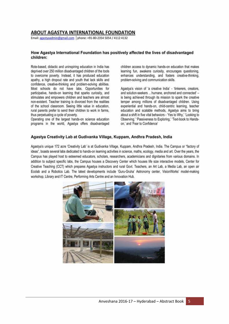
ABOUT AGASTYA
Anveshana 2016-17 – Hyderabad – Abstract Book 5
Anveshana 2016-17 – Hyderabad – Abstract Book 6

Anveshana 2016-17 – Hyderabad – Abstract Book 7
Anveshana 2016-17 – Hyderabad – Abstract Book 8
ABOUT SYNOPSYS
Corporate Background
Synopsys, Inc. (Nasdaq:SNPS) provides products and services that accelerate innovation in the global electronics market. As a leader in electronic design automation (EDA) and semiconductor intellectual property (IP), Synopsys' comprehensive integrated portfolio of system-level, IP, implementation, verification, manufacturing, optical and field-programmable gate array (FPGA) solutions help address the key challenges designers face such as power and yield management, system-to-silicon verification and time-to-results. These technology-leading solutions help give Synopsys customers a competitive edge in quickly bringing the best products to market while reducing costs and schedule risk. For more than 25 years, Synopsys has been at the heart of accelerating electronics innovation with engineers around the world having used Synopsys technology to successfully design and create billions of chips and systems. The company is headquartered in Mountain View, California, and has approximately 90 offices located throughout North America, Europe, Japan, Asia and India.
- See more at:
http://www.synopsys.com/Company/AboutSynopsys/Pages/About.aspx#sthash.GSEbLS7
b.dpuf

Anveshana 2016-17 – Hyderabad – Abstract Book 9
ABOUT ANVESHANA
Anveshana Program is structured around the concept of mentoring, “catch them young” and “facilitate the inquisitive minds”.
“Mentoring is a process for the informal transmission of knowledge, social capital, and the psychosocial support perceived by the recipient as relevant to work, career, or professional development; mentoring entails informal communication, usually face-to-face and during a sustained period of time, between a person who is perceived to have greater relevant knowledge, wisdom, or experience (the mentor) and a person who is perceived to have less (the protégé)" (source: http://en.wikipedia.org/wiki/Mentorship). The program looks at Involving school students to provide an opportunity to work with engineering students to find solutions for the encountered social problems. The program envisaged to bring together students from various underprivileged schools and Engineering colleges in respective locations in and around Delhi NCR – in a collaborative platform (Anveshana). Engineering colleges will participate as teams with 2 members. The teams will select 2 students from nearby underprivileged schools (Govt. and Govt. aided schools) to mentor them to design and build models or projects around an identified social problem. In the process school children would directly get the opportunity to work together with more qualified under-graduates, and a chance to ‘learn’ the basic principles (along with hands-on skills on diverse products and interesting processes). The interaction with Juries and dignitaries would be a life-time experience for them to cherish. The school students thus will be exposed to entire planning, designing and building process of the models and in turn will get educated in the scientific and engineering concepts behind the models in Anveshana-2016. (www.anveshana.org) Process of Anveshana (Engineering Fair & Competition):
Initial Screening of Engineering College Teams: Concept synopsis based on social
problems and related Engineering solutions are invited from engineering college teams
for pre-screening by the jury.
Screening, selection of Synopsis and identifying mentees: Once selected the teams are
asked to contact local schools with underprivileged status and to form school student
teams to plan, design and make the models, while collaborating and mentoring the high
school students.
Model Creation and Quality Check by Agastya team: Students will create knowledge
networks between them, their peers and with external resource persons to create
conceptual and methodological framework to create the models. Here, Agastya teams
along with assigned senior resource persons (senior educators, engineers etc.) will visit
the colleges to assist the teams conceptually and in the making of the models while
providing inputs including scientific and technological inputs. One of the main reasons

Anveshana 2016-17 – Hyderabad – Abstract Book 10
for these visits is to assure the quality of the collaboration and teaching-mentoring-
learning outcomes.
Conceptual- Technological advice from Agastya: Agastya will also help the teams to
establish links between prominent institutions like Indian Institute of Science, Institution
of Engineers, Indian Institute Technology etc. –in case they need any technological or
conceptual inputs.
Anveshana Fair begins: The models thus made will be exhibited in Anveshana
Engineering fair where the teams would be presenting the same in front of an expert
Jury for Judgment. During the fair, students display their research projects, working
models and present their findings orally and through written journals to the Jury (mostly
a team of scientists and educators). The judging process involves series of interactions
on the concepts, methodology and objectives of the projects done by the students.
Delegates attending the fair: After the judging process students from various schools
and delegates representing various institutions are also expected to attend the fair.
Delegates attending the event will include scientists and educators from large number of
institutions across Hyderabad.
Valedictory: Prizes will be awarded at a valedictory function –towards the end of the
fair.
ANVESHANA MILESTONES 2011 - 12 Anveshana launched in Bangalore
2012 - 13 Anveshana 2nd Edition in Bangalore
2013 - 14 Anveshana 3rd Edition in Bangalore
Anveshana Launched in Hyderabad
2014 - 15 Anveshana 4th Edition in Bangalore
Anveshana 2nd Edition in Hyderabad
2015 - 16 Anveshana 5th Edition in Bangalore
Anveshana 3rd Edition in Hyderabad
Anveshana Launched in NCR-Delhi
2016 - 17 Anveshana 6th Edition in Bangalore
Anveshana 4th Edition in Hyderabad
Anveshana 2nd Edition NCR-Delhi

Anveshana 2016-17 – Hyderabad – Abstract Book 11
PROJECT SCREENING COMMITTEE
MG Subramanian
MG Subramanian is an Advisor to Agastya International Foundation. He enjoys going around project sites-namely colleges where Anveshana’s projects are in progress interacting with young mentors and younger mentees pointing out the immense opportunities to teach and learn, to wonder and innovate.
He is an engineer from IIT Madras and an PGDM from IIM Calcutta with a long experience in manufacturing, product, business development and Human resources development. He acknowledges the value of a mentorship and attributes all his successes in life to his mentors .He says Anveshana’s success is inevitable!
Dr. H. G. Nagendra Dr. H. G. Nagendra is Professor and Head at the Department of Biotechnology, Sir MVIT, Bangalore. He holds a doctorate degree in Biophysics from IISc, Bangalore, and was a recipient of the BOYSCAST Post-doctoral Fellowship (DST) from Cambridge University, UK. He has 16 years of teaching and 20 years of research experience, and has authored 26 international publications in various journals. His research interests include protein bioinformatics and structural biology of neurodegenerative peptides. He has made more than 54 presentations at various conferences / seminars as an invited speaker, and has conducted more than 32 conferences / seminars / workshops. Dr. M Govindappa
Name: Dr M Govindappa
Qualification MSc, MPhil, PhD, PDF (USA) Research Publications
06 National 52 International
PhD guidance 03 students awarded (6 students pursuing)
Guided for BE, M.Tech and MSc students for their academic project work
Membership For various biotechnology bodies Reviewers For various journals
Editor for International Journal of Multidisciplinary Research

Anveshana 2016-17 – Hyderabad – Abstract Book 12
PROGRAM CHART
2017
22nd January 2017 3.30 pm to 4.30 pm Student Registration In the venue
4.45 pm Tea/Snack Break Compass Group
5.15 pm to 5.45 pm Agastya Vision Movie/ discussion
Mr. Suresh
5.45 pm to 6 pm About Synopsys Mr. Uno V. Nellore
7.30 pm DINNER Compass Group
23rd January 2017 8 am to 8.45 a Breakfast Compass Group
10 am Welcome Address Mr. F Mahavir Kumar
10.10 am Inauguration Ms.
10.20 am Guest Speech Mr.
10.30 to 1 pm Models Judging (Jury team) Dr. Vishwanath Gogte, Prof. T. Narayana, Dr. Somashekar Ms. Jayanthi Kasarla
1 pm to 1.30 pm LUNCH Compass Group
1.30 pm to 4.30 pm Models Judging Continues
4.30 to 5.30 pm Tea Break Compass Group
7.30 pm DINNER Compass Group
24th January 2017 8 am to 8.45 a Breakfast Compass Group
10 am to 1 pm Science Fair (Engineering Models)
Open to School Students & Visitors
1 pm to 1.30 pm LUNCH Compass Group
1.30 pm to 2.45 pm Science Fair (Engineering Models)
Open to School Students & Visitors
3 pm to 4pm Valedictory Ceremony Prize Distribution to winners
5 pm Tea Break
Anveshana 2016-17 – Hyderabad – Abstract Book 13
PROJECTS EXHIBITED IN THE FAIR
S.N PROJECT CODE
PROJECT TITLE COLLEGE NAME SCHOOL NAME
1 AS-E-01 LITHIUM ION BATTERIES FROM PURPURIN
CHADALAWADA RAMANAMMA ENGINEERING COLLEGE
H.M.M HIGH SCHOOL RAILWAY KODUR
2 AS-E-02 BLOOM ENERGY FOR THE FUTURE BY USING FUEL CELLS
SRI PADMAVATI MAHILA VISVAVIDYALAYAM
ZPHS TIRUCHANOOR
3 AS-E-03 SOLAR AIR CONDITIONING WITH PELTIER ELEMENTS
SRI PADMAVATI MAHILA VISVAVIDYALAYAM
ZPHS TIRUCHANOOR
4 AS-E-04 TO DESIGN AND FABRICATION OF HYDRAULIC MINI ROBOT
SREENVASA INSTITUTE OF TECHNOLOGY AND MANAGEMENT STUDIES
R.K VIDHYALAYA ENGILISH MEDIUM SCHOOL,CHITTOOR
5 AS-E-05 SOLAR TRACKING PHOTOVOLTAIC DEVICE
SRI VENKATESWARA COLLEGE OF ENGINEERING
ZPHS TIRUCHANOOR
6 AS-E-06 AUTOMATIC SIDE STAND RETRIEVING SYSTEM
N.B.K.R. INSTITUTE OF SCIENCE & TECHNOLOGY
ZP GIRLS HIGH SCHOOL,KOTA & ZPHS,KOTHAPALEM
7 AS-E-07 POWER GENERATION FROM VK0001 PANEL
SREEDEVI ENGINEERING COLLEGE
ZPHS VATTINAGULAPALLY
8 AS-E-08 PIEZO ELECTRICITY JAYA PRAKASH NARAYAN COLLEGE OF ENGINEERING
ZPHS DHARMAPUR
9 AS-WM-01
SMART WATER & WASTE MANAGEMENT
MUFFAKHAM JAH COLLEGE OF ENGINEERING AND TECHNOLOGY
MUKKARAM JAH HIGH SCHOOL
10 AS-WM-02
A HIGH SENSITIVE ALCOHOL SENSOR WITH AUTO CAR IGNITION
TKR ENGINEERING COLLEGE ZPHS KARMANGHAT
11 AS-WM-03
AUTOMATED SOLAR POWERED DRAIN CLEANER
SRI SAI JYOTHI ENGINEERING COLLEGE
ZPHS VATTINAGULAPALLY
12 AS-WM-04
BIO-PAPER MARRI LAXMAN REDDY INSTITUTE OF TECHNOLOGY
ZPBHS,MEDCHAL
13 AS-WM-05
SMART SANITATION SYSTEM FOR SUSTAINABLE SANITY
BV RAJU INSTITUTION OF TECHNOLOGY
VISHNU HIGH SCHOOL
14 AS-AG-01
AUTOMATIC CULTIVATION SYSTEM USING MICROCONTROLLER
ACE ENGINEERING COLLEGE ZPHS, KAPRA
15 AS-AG-02
ROCKER BOGIE ROBOT FOR PLANT IRRIGATION
MARRI LAXMAN REDDY INSTITUTE OF TECHNOLOGY
ZPHS KUKATPALLI

Anveshana 2016-17 – Hyderabad – Abstract Book 14
16 AS-A-01 PELTIER AIR COOLER VELAGAPUDI RAMAKRISHNA SIDDARTHA ENGINEERING COLLEGE
SRI NAVABHARATH SCHOOL,KRISHNALANKA
17 AS-G-01 REDUCTION OF ACCIDENTS BY ALCOHOL DETECTOR IN VEHICLES
BHOJREDDY ENGINEERING COLLEGE FOR WOMEN
M.H GUPTA HIGH SCHOOL
18 AS-G-02 TECHNOLOGICAL AID FOR DYSCALCULIA USING OPEN CV AND MINTER SYSTEM
G.NARAYANAMMA INSTITUTE OF TECHNOLOGY AND SCIENCE
G.PULLA REDDY HIGH SCHOOL
19 AS-G-03 E DUSTBIN AVANTHI INSTITUTE OF ENGINEERING AND TECHNOLOGY
ZPHS VANASTALIPURAM
20 AS-G-04 QUAD WHEEL OMNI-DIRECTIONAL ROBOT
MARRI LAXMAN REDDY INSTITUTE OF TECHNOLOGY
ZPHS KUKATPALLI
21 AS-G-05 MICROSTRIP ANTENNA MARRI LAXMAN REDDY INSTITUTE OF TECHNOLOGY
ZPHS KUKATPALLI
22 AS-G-06 SMART BED -SMART SOLUTION FOR BED SORES
MUFFAKHAM JAH COLLEGE OF ENGINEERING AND TECHNOLOGY
GIRLS HIGH SCHOOL,MAJEEDIA
23 AS-G-07 PHASE CHANGING MATERIALS(PCMS) USED AS BUILDING MATERIAL
PRINCETON COLLEGE OF ENGINEERING AND TECHNOLOGY
ZPHS GHATKESAR
24 AS-G-08 ROTATING BUILDING USING ENERGY
PRINCETON COLLEGE OF ENGINEERING AND TECHNOLOGY
ZPHS GHATKESAR
25 AS-G-09 ENERGY EFFICIENT ENGINES
VAAGESWARI COLLEGE OF ENGINEERING
ZPHS SEETHARAMPALLI
26 AS-G-10 TWO WHEELER BLIND SPOT DETECTION SYSTEM
CHADALAWADA RAMANAMMA ENGINEERING COLLEGE
S.V HIGH SCHOOL,TIRUPATI
27 AS-G-11 SMARTER LEVEL CROSSING SYSTEM
N.R.I.INSTITUTE OF TECHNOLOGY
SRI NAVABHARATH SCHOOL,KRISHNALANKA
28 AS-G-12 3-AXIS MEMS CONTROL WHEEL CHAIR FOR PATIENTS
SREEDEVI ENGINEERING COLLEGE
ZPHS VATTINAGULAPALLY
29 AS-G-13 BOMB DETECTION AND DIFFUSING ROBOT CONTROL
SREE DATTHA GROUP OF INSTITUTIONS
SLATE THE SCHOOL
30 AS-G-14 TEEKA G.NARAYANAMMA INSTITUTE OF TECHNOLOGY AND SCIENCE
ZPHS MANIKONDA
31 AS-G-15 ONLINE ORGAN BANKING SYSTEM
G.NARAYANAMMA INSTITUTE OF TECHNOLOGY AND SCIENCE
ZPHS MANIKONDA

Anveshana 2016-17 – Hyderabad – Abstract Book 15
32 AS-G-16 QUAD COPTER VBIT ENGINEERING COLLEGE
JHONSON ICSE MALLAPUR
33 AS-G-17 DIGITAL WATERMARKING MARRI LAXMAN REDDY INSTITUTE OF TECHNOLOGY
ZPHS KUKATPALLI
34 AS-G-18 PROVIDING SECURITY TO THE VEHICLE AND HUMANS USING GPS TRACKING SYSTEM
VNR VIGNANA JOTHI INSTITUTE OF ENGINEERING AND TECHNOLOGY
ZPHS BACHUPALLY

Anveshana 2016-17 – Hyderabad – Abstract Book 16
1. LITHIUM ION BATTERIES FROM PURPURIN
COLLEGE: CHADALAWADA RAMANAMMA ENGINEERING COLLEGE
GUIDE: PROF N. HARINDRA
SCHOOL STUDENTS: G.VEERANJANEYA REDDY 10TH STD, P.KHAJA 10TH STD, H.M.M HIGH SCHOOL ,RLY KODUR
COLLEGE STUDENTS: M.JAGADEESH, C. BHANU PRAKASH
ABSTRACT
The main concept of the fuel from water is electrolyzing water into HHO instead of Hydrogen and Oxygen ions. This technique was first introduced by Denny Klein, who just
patented his process of converting H2O to HHO producing a gas that combines the atomic
power of hydrogen with the chemical stability of water. An electrolyze which decomposes distilled water into a new fuel composed of hydrogen, oxygen and their molecular and monocular bonds, called HHO. The atoms in this Oxy-Hydrogen do not take a mono-atomic form, but are kept at diatomic state.
He initially designed this water burning engine so called BLU MAGIC CELL for cutting metal. He then thought that it would replace acetylene in welding factories. The study stated that it would nearly increase the fuel economy in these factories for around 60-70%. This system needs an energy input of about 12 volts and 16 amps. It would need an extra power of 200 watts for a light bulb present in the system.
The main advantage of this welding is, it can even weld metal to a glass and can also bring tungsten to the melting point at 60000C. The temperature of flame is 2590F and temperature can be exceeded by 100000F.
METHOD

Anveshana 2016-17 – Hyderabad – Abstract Book 17
EXPERIMENT
Basic Principle: H2O to 2H+O.
The world is looking for an alternative source of energy to cope with the ever increasing demand of power. Government and many other companies are spending huge money in the Research and Development of other mode of fuel/power in all over the world. Oil and gas resources are limited. There is a gap between the demand and supply. It is up to us how to utilize limited resources wisely. The idea of integrating Hydrogen Boosters to an IC Engine minimizes the fuel consumption, helps to minimize noise, vibration and improve the efficiency of the Engine.
Combustion in an IC Engine occurs by the burning of air fuel mixture. The idea of integrating Hydrogen boosters is the addition of Hydrogen and Oxygen obtained from Electrolysis of distilled water added with catalyst to air before entering into carburetor.
The main objective of this project is to discuss how to build the device, working principle, installation process to a vehicle and to show variation in the performance characteristics of an IC Engine with and without integrating of Hydrogen Boosters.
Our motto is to generate powerful hydrogen gas for free from water by including various technical methods in electrolysis process to generate more and pure form of hydrogen and oxygen. This fuel as a supplementary not only enhances the combustion process, which results in high mileage but also reduces carbon emissions in the engine.
SUMMARY
We produced fuel from water successfully by using available low cost materials
COST
INR 1500/-

Anveshana 2016-17 – Hyderabad – Abstract Book 18
2. BLOOM ENERGY FOR THE FUTURE BY FUEL CELLS
COLLEGE: SRI PADMAVATHI MAHILA UNIVERSITY ,TIRUPATHI
GUIDE: I.SIVAAPRASAD
SCHOOL STUDENTS: M.HEMALATAH 9 th STD & K.VIJAY 8th ZPHS TIRUCHANUR
COLLEGE STUDENTS: P.RAHULIDEVI,P.MUNISWARI
ABSTRACT
In the current world, we are facing issues with availability and production of electricity for present and future generations. There is a need to generate alternative methods in producing electrical energy that are reliable, flexible and less polluting from low cost materials assuring continuous supply. Our project aims at one such alternative method called the bloom energy. Bloom energy is manufacturer of fuel cell. It is a heart of every energy server.
There are different types of fuel cells. They are:
1. Alkaline fuel cells 2. Phosphoric acid fuel cells 3. Proton exchange membrane fuel cells 4. Solid oxide fuel cells 5. Molten carbonate fuel cells
Alkaline fuel cells are used at space and rocket applications. Phosphoric acid fuel cells are used at buildings, hospitals, commercial applications. Proton exchange membrane fuel cells are used at automobiles applications. Solid oxide fuel cells are used at industrial applications. Molten carbonate fuel cells are used at proto type and testing applications.
HYPOTHESIS
Fuel cells have been around longer than Batteries. They generate Electricity from the
reaction of hydrogen with oxygen to form water. This process is the reverse of Electrolysis.
The principle of working is conversion of chemical energy into electrical energy.
METHOD
A fuel cell is an electrochemical cell that converts a source fuel into electric current. It
generates electricity inside a cell through reaction between a fuel and an Oxidant, trigged in
the presence of an electrolyte. In a fuel cell the anode usually is balanced in the fuel, the
cathode collects and makes available the oxidant and ion conducting membrane separates
the two, allowing the reaction to takes place without affecting the Electrodes. The fuel cell
produces electricity as long as the cell receives a supply of fuel and can dispose of the
oxidized old fuel.

Anveshana 2016-17 – Hyderabad – Abstract Book 19
EXPERIMENT
CONSTRUCTION
Membrane: A material which acts as a barrier and transfers only hydrogen ions and not electrons. Anode: Anode acts as a catalyst which disassociates hydrogen into hydrogen ions and electrons and the material used for anode is platinum. Cathode: Cathode is also acts as a catalyst which combines hydrogen and oxygen ions into water. Gas division layer: It is placed on both sides on anode and cathode side. Its functions is to pass hydrogen and oxygen gas through it. Bipolar plate: It is used to connect number of fuel cells in series and form as fuel cell stack to increase voltage levels. Current collector: It is used to collect electricity and pass to the external circuit.

Anveshana 2016-17 – Hyderabad – Abstract Book 20
WORKING
The fuels required for this project are hydrogen and oxygen. These gases are produced in many ways. Mainly two methods are used
1. Steam reforming process. 2. Electrolysis of water.
Electolyzer: The purpose of electrolyzer is to separate hydrogen and oxygen from water. Here fuel cell acts as an electrolyzer. In electrolysis of water ,we are taking two glass containers filled with some level of distilled water and connecting to electrolyzer through rubber tube .By giving supply to the electrolyzer using battery or solar panel its separates the hydrogen and oxygen gas.
Block diagram for electrical energy generation using fuel cell
As shown in above figure remove the solar panel or battery supply and connect external circuit or load. In this process electrolyzer acts as fuel cell. By taking hydrogen and oxygen gas from gas containers, it converts chemical energy (hydrogen and oxygen fuel) into electrical energy.
SUMMARY:
Anveshana 2016-17 – Hyderabad – Abstract Book 21
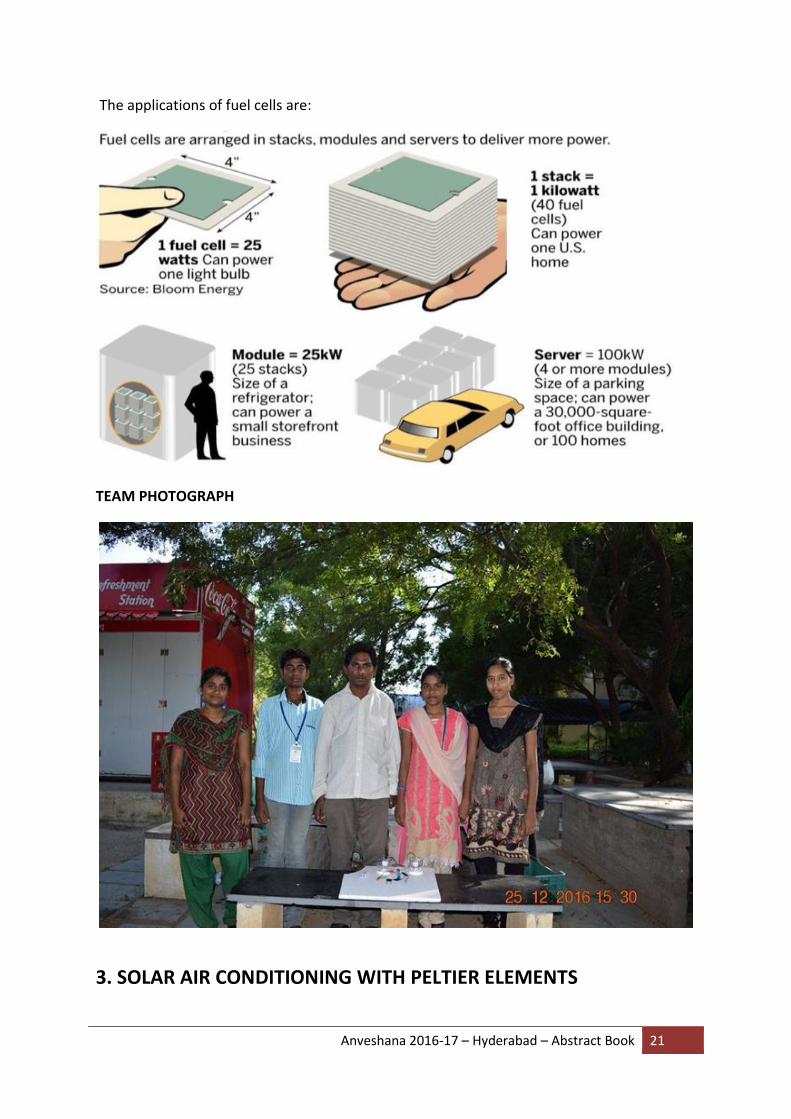
The applications of fuel cells are:
TEAM PHOTOGRAPH
3. SOLAR AIR CONDITIONING WITH PELTIER ELEMENTS

Anveshana 2016-17 – Hyderabad – Abstract Book 22
COLLEGE: SRI PADMAVATHI MAHILA UNIVERSITY
GUIDE: P.UMA MAHESH
SCHOOL STUDENTS: VISWAS,NANDINI AND PAVITHRA ,ZPHS TIRUCHANUR
COLLEGE STUDENTS: P.SRAVANTHI,K.SAMATHA
ABSTRACT: The purpose of this project has been to investigate the possibility of heating and cooling air by connecting Peltier Elements to a PV panel. The “climate panel” developed is to be used as a compliment to an existing heating system in order to pre-heat and pre-cool the air coming into the house. By decreasing the heating demand in winter and cooling demand in summer the panel could contribute to lowering the annual energy need and thereby save money. The aim of this project has been to investigate the potential for such a panel, and to perform an economic evaluation in comparison to common Swedish heating systems. The result presented in this report is based on theoretical and practical simulations. A prototype design has been developed along with the company and tested in their workshop.There are many uncertainties connected to the theoretical model and the practical results and further testing is needed to fully evaluate the system. The conclusion is that there is great potential in developing this product, and that it can be used as a complement to an existing heating system to save both energy and money. Using solar energy to boost the heat production of a building is a sustainable way to reduce the environmental impact and cut the costs, which is why the climate panel should be developed further. Solar energy is not available in all climate conditions for that purpose we store the solar energy by using invertor. To control the room temperature (cooling and heating) automatically and on-off by using temperature thermocouple sensor system. APPLICATIONS: Can be used as home air conditioning system for poor and below medium class houses. Can be adopted as a cooling system for Traffic police posts. Enable people of those rural areas which do not have electricity supply to have cool air during summer days It is also available to ordinary people at lower costs when compared to electrical air cooling.
INTRODUCTION: The comfort conditions achieved by the device for the human body. In summer (hot) and humid conditions feel uncomfortable because of hot weather and heavy humidity. So it is necessary to maintain thermal comfort conditions. Thermal comfort is determined by the room’s temperature, humidity and air speed. Radiant heat (hot surfaces) or radiant heat loss (cold surfaces) are also important factors for thermal comfort. Relative humidity (RH) is a measure of the moisture in the air, compared to the potential saturation level. Warmer air can hold more moisture. When you approach 100% humidity, the air moisture condenses – this is called the dew point. The temperature in a building is based on the outside

Anveshana 2016-17 – Hyderabad – Abstract Book 23
temperature and sun loading plus whatever heating or cooling is added by the HVAC or other heating and cooling sources. Room occupants also add heat to the room since the normal body temperature is much higher than the room temperature. Need of such a source which is abundantly available in nature, which does not impose any bad effects on earth.
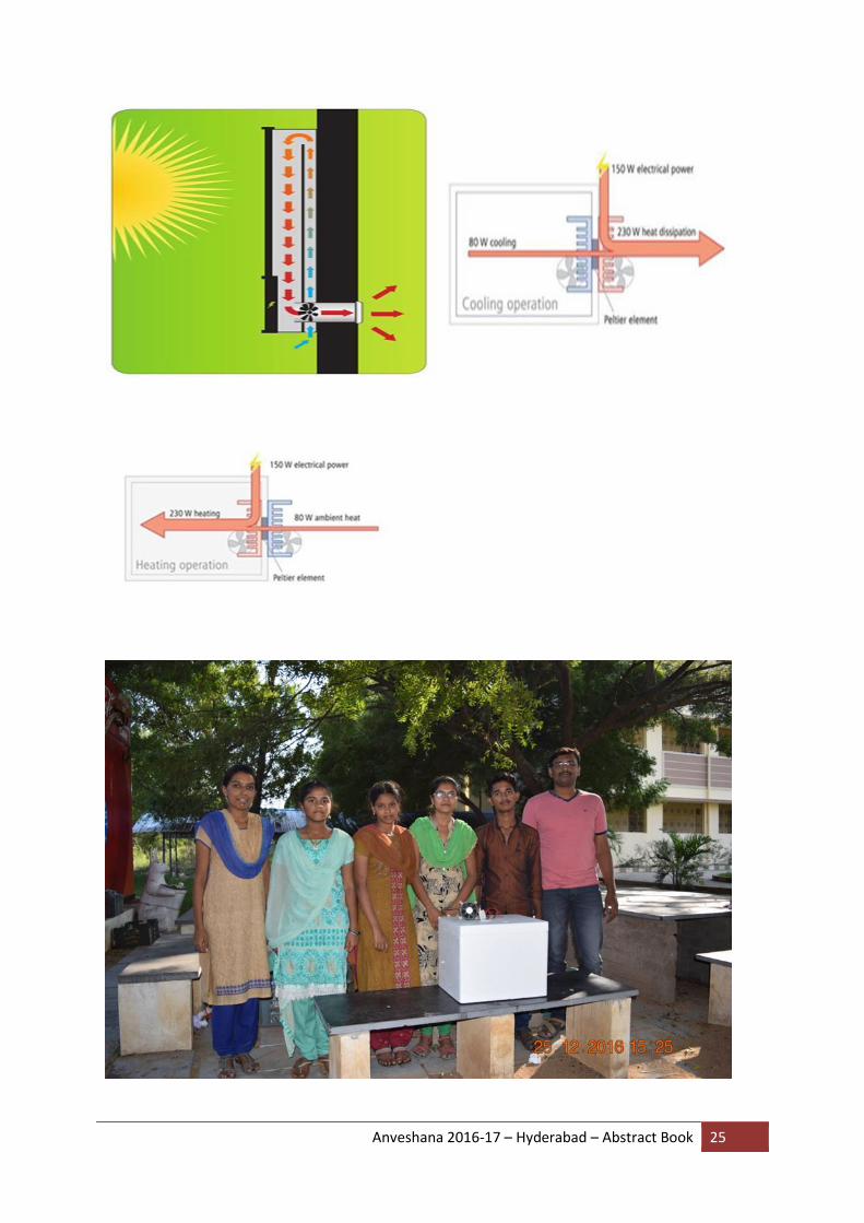
Solar panels are used as a passive solution in summer houses to induce air circulation inside the house during winter. By using the electricity from a solar panel to power Peltier elements, the company strives to develop a product that can heat and cool air. Peltier elements are small devices which, when powered by a direct current, gets a hot and a cold side. If the direction of the current in changed the hot and cold side swaps places. This property makes the elements favorable to use in this solar driven heat pump. By swapping direction of the current the air can be either heated or cooled, which makes it possible to use the product as an all year solution. In summer the system can be used as an air conditioner and in winter as a heat pump. The overall output is not expected to be enough to provide heating for a whole house, and the Peltier elements will only be active as the sun shines. Therefore this product is planned to be used as a complement to an existing heating system only, alternatively as a separate solution for summer houses. The purpose of this project is to determine whether it is possible to design such a product and evaluate its potential.
BACKGROUND:
Solar energy: The sun's energy relies on nuclear fusion, which is an atomic reaction in which the centers of atoms (nuclei) of one kind combine together to make a larger atom of a different kind. One result of this bashing together is the release of a great amount of energy. In the sun, hydrogen is converted to helium. In solar atomic fusion four hydrogen nuclei join together to form a single helium nucleus. Heat: Heat is the energy associated with the random motions of the atoms or molecules (or even smaller units) that compose matter. Heat causes substances to rise in temperature, fuse, evaporate, expand, or undergo various other related changes. Cold: Cold is the absence of heat, nothing more. This is an important point! When you chill something, you don't "add" cold, you "subtract" heat. Heat Transfer: Conduction, convection and radiation are the three ways in which heat is transferred from one place to another. Conduction: Conduction is the transfer of heat through matter, particle by particle. Molecules move when heated, and collide with one another. As a result of the collision, energy and momentum are exchanged and transferred from one particle to another, in effect transferring heat. Convection: Convection is the transfer of heat through the movement of gases or liquids ("fluids"). This circulatory movement occurs when a nonuniform temperature exists in a fluid. Warmer, less dense fluid is pushed away from the source of heat by cooler, denser matter. The moving fluid carries energy with it. Currents in the ocean form due to

Anveshana 2016-17 – Hyderabad – Abstract Book 24
convection, with water at the equator gaining more heat from the sun than water at the poles. Weather patterns develop in direct relation to these ocean currents - witness the El Niño and La Niña patterns related to changes in current flow, due to cooling and warming in the Pacific Ocean. Radiation: Radiation is the transfer of heat that does not require matter in transmission. It is energy traveling as electromagnetic waves. The Laws of Thermodynamics: These laws describe the system of heat energy. They encompass these (and other) ideas: Energy is never created or destroyed, but is converted from one form to another. At times, energy dissipates and it is hard to measure, but it is never "lost." Heat energy flows in one direction, from warmer matter to cooler, until equilibrium is struck. Also, when energy is transferred or transformed, part of energy assumes a form that cannot pass on any further. Working prototype: The design of the climate panel has been inspired by existing panels for solar air heating. These panels consist of two parts, one black surface which heats up when the sun shines, and one small surface of PV cells. The electricity produced by the PV cells is used to run a circulation fan. Air is taken into the panel and heated up when passing the black surface. Hot dry air is then blown into the house by the fan. The purpose of this panel is to create air circulation within the house and keep the moisture level down, mainly in winter. The simple function is described in figure 11 below. According to manufacturer the panel shown can achieve a temperature increase of up to 30°C.
Anveshana 2016-17 – Hyderabad – Abstract Book 25
Anveshana 2016-17 – Hyderabad – Abstract Book 26
4. DESIGN AND FABRICATION OF HYDRAULIC MINI ROBOT
COLLEGE: SRINIVASA INSTITUTE OF TECHNOLOGY AND MANAGEMENT STUDIES
GUIDE: Dr S. RAJESH
SCHOOL STUDENTS: YAMUNA A, 9th std, THRUSHITHA O.G, 9th std R.K. VIDYALAYA ENGLISH MEDIUM SCHOOL IRRUVARAM.
COLLEGE STUDENTS: MOHAN KRISHNA S & BHARGAV KUMAR REDDY P.G
ABSTRACT
Nowadays new implementation of robotics is in humanoid robots. It is more flexible and efficient. The design (i.e. designing of gears, links and joints etc.) and manufacturing of humanoid robots take more time and is more complex. Humanoid robots operate on electrical energy. Nowadays the availability of the electrical energy is difficult and is more costly, to avoid this loss we can implement the hydraulic mini robot based on hydraulic properties. Our main objective is TO DESIGN AND FABRICATE HYDRAULIC MINI ROBOT, with involvement of only mechanical engineering. The materials chosen are weightless wood, syringes, pipe tube, screws etc. This robot is working under the hydraulic pressure. Here the hydraulic fluid we are considering is water, by using hydraulic pressure to test how much weight the robot can lift. Presently the hydraulic robots are not implemented; future implementation of the robot can benefit us, and also in future we can increase the size of the robot. Presently it can lift only 200 gms, in future we can design the hydraulic robot that can lift weights more than 100kgs.
PROJECT DESCRIPTION
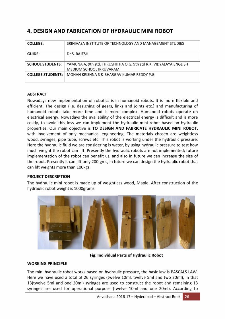
The hydraulic mini robot is made up of weightless wood, Maple. After construction of the hydraulic robot weight is 1000grams.
Fig: Individual Parts of Hydraulic Robot
WORKING PRINCIPLE
The mini hydraulic robot works based on hydraulic pressure, the basic law is PASCALS LAW. Here we have used a total of 26 syringes (twelve 10ml, twelve 5ml and two 20ml), in that 13(twelve 5ml and one 20ml) syringes are used to construct the robot and remaining 13 syringes are used for operational purpose (twelve 10ml and one 20ml). According to

Anveshana 2016-17 – Hyderabad – Abstract Book 27
sequence of operations we give numbers to syringes, 1 to 6 from left side and 1 to 6 from right side both robot side and operation side in between 20ml syringes are placed.
Suppose consider right side we pull the syringe 1 in the operation side, the robot palm can open to hold any objects, we push the syringe back to close it.
We push syringe 2 in the operation side the robot can lift half-of the hand up to elbow and we pull the syringe its comes down.
We push syringe-3 in the operation side the robot can moves the hand up and we pull the syringe it comes down.
The syringes 4 and 5 are used to move the legs by using pulling and pushing operations.
The syringe 6 is used to operate the foot of the robot based on pull and push operations.
The special 20ml syringe is used for bending purpose of the robot by using pulling and pushing operations.
Now we are considering left side same as the right side operations.
DIFFERENCES OF THE ROBOTICS AND HYDRAULIC ROBOT
ROBOTICS HYDRAULIC ROBOT
1. Robotics has high efficiency. 2. The cost of the robotics is very high. 3. The robotics runs with electrical power. 4. Here using the various mechanisms such
as gears, kinematic chains, links, joints etc.
5. Once it can be repair, the repairing cost is high as compared to hydraulic robot.
6. The constructional cost is high. 7. The design and fabrication is very
difficult as compared to hydraulic robots.
1. The hydraulic robot also has high
efficiency. 2. The cost of hydraulic robots is low as
compared to robotics. 3. The hydraulic robot runs with hydraulic
pressure only. 4. The hydraulic robot has only simple links,
joints etc. 5. The repairing cost is low as compared to
robotics. 6. The constructional cost is low. 7. The design and fabrication is very easy.
ADVANTAGES OF HYDRAULIC ROBOT
(i) The cost of the hydraulic robot is low.
(ii) The design and construction is very easy as compared to robotics.
(iii) This robot works under the hydraulic pressure and we are using the hydraulic fluid
as water which is abundantly available.

Anveshana 2016-17 – Hyderabad – Abstract Book 28
DIS-ADVANTATEGES OF HYDRAULUIC ROBOT:
(i) The life time of the syringes is low as compared to rams.
(ii) We are considering water or oil both which have certain limits.
(iii) We can choose the proper material such as metal or wood.
(iv) The life time of the wood is low, compared to the metal.
Fig: assembling of Hydraulic Robot (front view)
FUTURE SCOPE
Currently hydraulic robots are not widely implemented; in future we can implement
hydraulic robots, and also in future we can increase the size of the robot. Presently it lifts
only 200 gms, in future we make it increase lift more than 100 kgs.
REFERENCES
a text book of hydraulics of fluid mechanics (R. K. BANSAL) a text book of hydraulics and pneumatics (ANTONY ESPOSITO) a text book of robotics and automation (M.P.GROOVER) a text book of robotics (FUU)
Anveshana 2016-17 – Hyderabad – Abstract Book 29
5. SOLAR TRACKING PHOTOVOLTAIC DEVICE
COLLEGE: SRI VENKATESWARA COLLEGE OF ENGINEERING, TIRUPATI.
GUIDE: P.UMA MAHESH
SCHOOL STUDENTS: B.ESWAR – 8TH STD, J.RAVI TEJA – 9TH STD, ZPHS TIRUCHANOOR
COLLEGE STUDENTS: HIMA BINDU PASUPULETI – III B.TECH(EEE), K.SAI CHARAN – IV B.TECH(MECHANICAL)
ABSTRACT
The world population is increasing day by day and the demand for energy is increasing accordingly. Oil and coal have been the major sources of energy for quite some time now. But their inevitable exhaustion forces us to find other affordable and reliable sources of energy. Hence, it is inevitable that we go for alternate sources of energy which also protect our environment from further degradation. Solar energy, in addition to fulfilling all these requirements, is abundant in countries like India which are nearer to equator and harvesting it is advantageous to us.
Nowadays solar energy is collected and stored using solar panels but the problem associated with this is that the solar panels in use are of fixed orientation while the angle of incidence of sun varies in different seasons. Maximum power generation in a solar panel occurs when the angle of incidence of sun rays is in normal direction to the incident radiation.
Therefore, in order to collect maximum solar radiation, the panel needs to be rotated in accordance to the direction of the sun. This brings about the need of building a solar tracking device along with the usual solar panel. The two general forms of tracking used are fixed control algorithms and dynamic tracking. The inherent difference between the two methods is the manner in which the path of the sun is determined. In the fixed control algorithm systems, the path of the sun is determined by referencing an algorithm that calculates the position of the sun for each time period. That is, the control system does not actively find the sun's position but works it out given the current time, day, month, and year. The dynamic tracking system, on the other hand, actively searches for the sun's position at any time of day.
HYPOTHESIS
Solar Tracker is a Device which follows the movement of the sun throughout the day. It orients the photovoltaic array toward the sun. In flat-panel photovoltaic (PV) applications, trackers are used to minimize the angle of incidence between the incoming light and a photovoltaic panel. This increases the amount of energy produced by the photovoltaic array. Solar trackers can increase the output of solar panels by 20-30% thereby making the solar power generation economical.
Solar tracking can be done in two ways:

Anveshana 2016-17 – Hyderabad – Abstract Book 30
single axis tracking
dual axis tracking
A single-axis tracker can only pivot in one plane – either horizontally or vertically. This makes it less complicated and generally cheaper than a two-axis tracker, but also less effective at harvesting the total solar energy available at a site. A horizontal tracker is used at equatorial latitudes and a vertical tracker is used at higher latitudes.
Dual axis solar tracker, as the name suggests, can rotate simultaneously in horizontal and vertical directions, and so is able to point exactly at the sun at all times in any location. These tracking systems naturally provide the best performance as compared to single axis trackers.
METHOD
The block diagram shown below illustrates the basic setup of a dual axis solar tracking system.
The electrical system consists of five LDR sensors which provide feedback to a micro controller. This micro controller processes the sensor input and provides signals to the motor. The motors then move the solar panel towards the higher density of solar light. The entire electrical system is powered by a 12 volt source power supply.
EXPERIMENT
A picture of the experimental setup is shown below. The various components used in this experiment along with the specifications are:
Solar panel : 7.5V, 1.3W
clamps and frames
LDR
12 volt battery
Arduino UNO
DC motor : 10 rpm, 12 V
Gears and shaft

Anveshana 2016-17 – Hyderabad – Abstract Book 31
SUMMARY
Solar energy has many advantages:
Needs no fuel
Has no moving parts which might wear out
Pollution free
Adaptable for on-site installation
Easy maintenance
Can be integrated with other renewable energy sources
It is estimated that if all the available solar radiation in India is harvested then it easily surpasses the energy requirement of our country. But the already established solar plants have a major drawback of decreased efficiency due to inefficient collection of solar radiation. In these conditions, this project maximizes the solar radiation collected and thereby maximizes the output.
COST
Rs.1300/-

Anveshana 2016-17 – Hyderabad – Abstract Book 32
6. AUTOMATIC SIDE STAND RETRIEVING SYSTEM
COLLEGE: NBKR INSTITUTE OF SCIENCE AND TECHNOLOGY, VIDYANAGAR
GUIDE: DR. S INDUMATHI
SCHOOL STUDENTS: CHALLA SUJITH, 9TH STD, ZPHS, KOTHAPALEM, M. DOLLY SAIPREMA, 10TH STD, ZP GIRLS HIGH SCHOOL
COLLEGE STUDENTS: DASARRAJU VEENA DEVI, SURABHI VEDA NARAYANA PARASAR
ABSTRACT
Nowadays a lot of two wheeler accidents are occurring due to not lifting off the side stand.
This can result in damage to bike, driver also sometimes pedestrians and can be more fatal
at times. In this project mainly focus on lifting the side stand automatically when the bike
starts moving. Our project may avoid those type of damages to the people and to the bike.
The stand automatically lifts off from its position when the bike starts moving i.e, when the
rider switches the gear to first gear from neutral. We used complete mechanical which
comprises of kinematic links and springs.
HYPOTHESIS
The gear shifting pattern is assumed to be forward as most of the bikes follow the same
pattern and also the rider is assumed to shift the gear after starting the engine but not
before starting as most bikes do not start when clutch is applied.
METHOD
Many people forget to lift the side stand before moving the vehicle. This mechanism comes
into aid for them. There is no change in the method of riding, the side stand automatically
lifts off when the gear is shifted to first gear.
The shifter lever applies force on a link which holds the side stand with spring force; the side
stand gets disengaged from the link when the link is pulled back. The mechanism uses two
springs and two levers.
Anveshana 2016-17 – Hyderabad – Abstract Book 33
OPERATIONS PERFORMED First a small metal plate was welded to the gear shifter rod where the contact with the
linkage mechanism happens. The shifter rod is fixed to the wooden board then with the help
of bolts and nuts. Then to the stand a hole of eyebolt stud diameter was drilled. Then the
eye bolt was welded to the stand. The stand was then fixed to the wooden board with the
help of bolts and nuts on one end of the flattened surface of the stand. Then the linkage
mechanism (Star key- spring mechanism) was positioned correctly such that it can support
for both the gear shifter rod and the stand. Then one end of the spring is attached to the
opposite side of the fixed eye bolt to the stand. Other end of the spring is attached to the
fixed support such that it should have sufficient tension in it to lift the stand. To the wooden
board fix two supports to place it in an inclined manner on the ground.
SUMMARY
This simple mechanism helps in reducing accidents caused due to the side stand. The mechanism can be altered to suit the bikes with other types of gear patterns. As no software or electrical components are used, chances of failure are very low.
COST
Gear, side stand, levers and springs from scrap 30 rupees
Wooden plank 30 rupees
Stickering 40 rupees
TOTAL 100 rupees
Anveshana 2016-17 – Hyderabad – Abstract Book 34
7. POWER GENERATION FROM VK0001 WITHOUT SOLAR PANEL
COLLEGE: SRIDEVI WOMENS ENGINEERING COLLEGE
GUIDE: TULASI RAM
SCHOOL STUDENTS: CH. NAGARAJU ( 8TH STD ) , NAGENDRAMMA( 9TH STD) , ZPHS
COLLEGE STUDENTS: P. SREELEKHA, NEHA TABASSUM
ABSTRACT
Before years natural power generation is expandable and costly project for home and industrial areas but these days it might be very common topic for installing natural power sources like solar panels and wind. My idea about power generation is that we can’t create natural power sources but we can retrieve power which already exists in universe like sun and air. Power generation from sun with solar panel only existed.
What do you think? Can an invention generate power from sun but WITHOUT SOLAR PANEL This paper publishes & reveals concept of power generation form sun by using without solar panel is designed
KEYWORDS: Solar, without solar panel, without solar panel power generation, solar power VK0001 panel, natural power generation, electrical solar power VK0001.
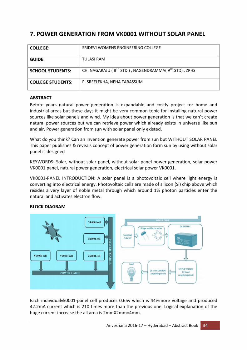
VK0001-PANEL INTRODUCTION: A solar panel is a photovoltaic cell where light energy is converting into electrical energy. Photovoltaic cells are made of silicon (Si) chip above which resides a very layer of noble metal through which around 1% photon particles enter the natural and activates electron flow.
BLOCK DIAGRAM
Each individualvk0001-panel cell produces 0.65v which is 44%more voltage and produced 42.2mA current which is 210 times more than the previous one. Logical explanation of the huge current increase the all area is 2mmX2mm=4mm.

Anveshana 2016-17 – Hyderabad – Abstract Book 35
The vk0001 panel is made up of major-silicon material manufactured by single –diffusion process. VK0001 cell poles are uniformly doped silicon slice the resulting homogeneously doped based region is free from accelerating field in bottom poles it generates the high current generation. These cells are type of archaebacterium: Mean single–celled microorganisms, these microbes are prokaryotes meaning that this has no cell nucleus or any other membrane-bound organelles in their cells.
Temperature operation can handle 2000C and -650Ccell is protects with aluminum heat sinker and mica insulator electrically 180 lattes the cell case from the heat silk AB2-3(X,si) 4ow (o,f,OH)2 Chemically, micas can be given the general formulaX2Y4–6Z8O20(OH,F)4 In which X is K, Na, or Ca or less commonly Ba, Rb, or Cs;Y is Al, Mg, or Fe or less commonly Mn, Cr, Ti, Li, etc.; Z is chiefly Si or Al, but also may include Fe3+ or Ti. Main power production area made up of semiconductor cell.
MAIN FEATURES: Solar power generation with our solar panel. Power amplification Circuits. Conversion of 12v to 230v Amplifying the current. This storage energy we are using for home applications, this voltage retrieves and converts DC to AC voltage to activate CFL bulb. Received voltage from the vk0001cell is charges the battery and it converts the voltage in to 230 voltage by the way it amplifies the current to activate CFL bulb.
ADVANTAGES
1. This panel produces voltage number of times better than earlier solar panel. 2. It can handle temperature -65c to 200c. 3. No need of glass layer to protect like old solar panel. 4. Powerful heat sink is fixed to cells 5. Low cost production. 6. This panel can decrease the home current billing. 7. Charging time decreases apparently.
HARDWARE USED The hardware requirements in this project are solar cells (power amplifier transistors), silicon gel, polarity checker, battery, RPS circuit, inverter circuit which consists of MOSFET’s, step-up transformer, resistors, capacitors and connecting wires
METHOD
Solar power generation without solar panel is by using Power amplification Circuits. Conversion of 12v to 230v Amplifying the current. We use this storage energy for for home applications, this voltage retrieves and converts DC to AC voltage to activate CFL bulb. Received voltage from the vk0001cell is charges the battery and it converts the voltage in to 230 voltage by the way it amplifies the current to activate CFL bulb.
EXPERIMENT
Solar power generation without solar panel is by using Power amplification Circuits. Conversion of 12v to 230v Amplifying the current. This storage energy we are using for home applications, this voltage retrieves and converts DC to AC voltage to activate CFL bulb.

Anveshana 2016-17 – Hyderabad – Abstract Book 36
Received voltage from the vk0001cell is charges the battery and it converts the voltage in to 230 voltage by the way it amplifies the current to activate CFL bulb.
SUMMARY
This project is an alternate method where power is generated without solar panel using power amplifier transistors as solar cells for the mobile charging and activation of CFL Bulb.
COST: Rs.6000/-
Anveshana 2016-17 – Hyderabad – Abstract Book 37
8. PIEZO ELECTRICITY COLLEGE: JAYAPRAKASH NARAYAN COLLEGE OF ENGINEERING
GUIDE: K.DAVID KIRAN
SCHOOL STUDENTS: K AKHIL KUMAR, K.VAMSHI KRISHNA, ZPHS DHARMAPUR
COLLEGE STUDENTS: G.ROHIT, Y.DIVYA
ABSTRACT
Piezoelectricity is electrical energy produced from mechanical pressure (including motions such as walking). When pressure is applied to an object, a negative charge is produced on the expanded side and a positive charge on the compressed side. Once the pressure relieved, electrical current flows across the material.
Let's look at how the principle works in a motion such as walking. A single footstep causes pressure when the foot hits the floor. When the flooring is engineered with piezoelectric technology, the electrical charge produced by that pressure is captured by floor sensors, converted to an electrical charge by piezo materials (usually in the form of crystals or ceramics), then stored and used as a power source.
Recently piezoelectric floors have debuted in a handful of innovative dance clubs around the world. These floors represent prototypes of the "Crowd Farm" concept: The movement of a large group of clubbers dancing on energy-capturing floors is collected and used to power LED lights and, in the long-term plan, feed energy into the club's power grid.
The principles of piezoelectricity have been understood since the 19th century but the application in energy-generating floors hasn't yet proven to be a substantial power source. In trials outside of the clubs, a "smart home" student housing experiment at Duke University ditched the idea of installing a piezoelectric floor when the high installation costs and nominal amount of power produced got in the way. In the clubs, initial estimates suggest an individual club could generate roughly 5 to 10 watts, and on a night where the dance floor is packed with moving bodies, the energy from the floor could supply about 60 percent of the club's total energy needs.
HYPOTHESIS
As we know the world today runs on electronic gadgets which does have many utilities, where charging the gadget is a major concern. For example, if we are using a mobile phone in areas where there is no electricity, there is no possible way to charge the mobile using charger provided to the mobile. If there is any, the only way is to provide charge to the battery. If we make use of generators, we need to rotate the generator with our hands. The other ways of generating electricity instantly is from natural resources like solar energy from Solar panels, wind energy from wind turbines. If we make use of solar panels, it will charge the battery in the presence of proper light only.

Anveshana 2016-17 – Hyderabad – Abstract Book 38
It is difficult to implement wind energy every time to charge the battery as there will be no continuous wind at all times. Hence there is a need of a source to produce energy at any time.
We know that “energy can be neither created nor destroyed”, but it can be transformed from one form to other.
Actually humans waste their energy on their daily activities like walking, jogging, running etc. If there is a way to convert this energy into electricity we can charge our gadgets without making use of other energy resources.
Hence we come across piezo-materials; these are the materials which can generate energy when stress or pressure is applied on it. When compared with solar energy and wind energy, the piezo materials can generate energy even in the absence of light and wind. So we can make use of piezo materials to charge our gadgets.
METHOD In order to generate energy from the piezo materials, they are to be subjected to strain. Hence we can take an example as shoes, if the shoes soles are embedded with piezo cells, they can generate energy while running or walking.
We can use this method at door mats, steps, pubs, shopping malls and many other places.
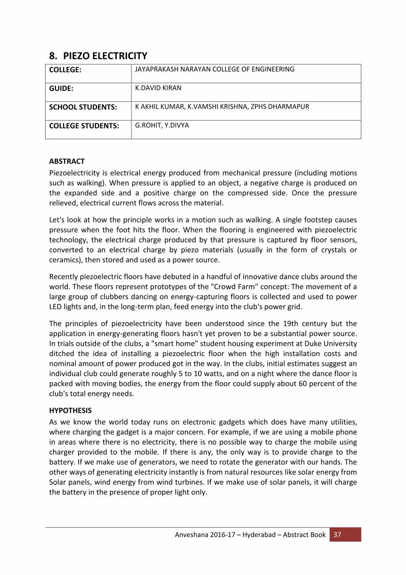
EXPERIMENT
PIEZO CELLS EMBEDDED PLANKS: In this the cells are connected in parallel but not in series because the parallel connection of piezo cells provide more current when compared to the series connection as shown in the following graph.
Anveshana 2016-17 – Hyderabad – Abstract Book 39
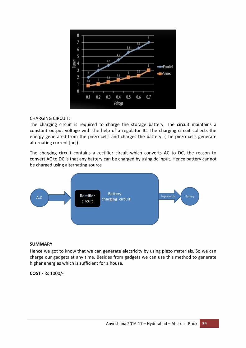
CHARGING CIRCUIT: The charging circuit is required to charge the storage battery. The circuit maintains a constant output voltage with the help of a regulator IC. The charging circuit collects the energy generated from the piezo cells and charges the battery. (The piezo cells generate alternating current [ac]).
The charging circuit contains a rectifier circuit which converts AC to DC, the reason to convert AC to DC is that any battery can be charged by using dc input. Hence battery cannot be charged using alternating source
SUMMARY
Hence we got to know that we can generate electricity by using piezo materials. So we can charge our gadgets at any time. Besides from gadgets we can use this method to generate higher energies which is sufficient for a house.
COST - Rs 1000/-
Anveshana 2016-17 – Hyderabad – Abstract Book 40
9. SMART WATER AND WASTE MANAGEMENT
COLLEGE: MUFFAKHAM JAH COLLEGE OF ENGINEERING AND TECHNOLOGY
GUIDE: Dr. MOHAMMED ARIFUUDIN SOHEL
SCHOOL STUDENTS: RAHMATULLAH QUAEMUDDIN, 9th STD, MIRZA HYDER ABBAS, 9th STD, MUKKARAM JAH HIGH SCHOOL
COLLEGE STUDENTS: HUMAIR AHMED KHAN AQIB, HUZAIFA NAYEEM, GHAZAIA ANJUM, SAMREEN SULTANA
ABSTRACT
One of the major challenges of the modern times that need an utmost importance is management of water and waste; this is faced by both the developed and developing countries. Water is a vital resource for life, and its management is a key issue nowadays. Almost 1/3th percent of water is lost before it reaches the customers due to the lack of support of standardization in monitory and control equipment. This problem affects various processes in water management, such as water consumption, distribution, leakage identification and equipment maintenance. Other major concern with environment is the waste management system.
We often come across waste bins placed at public places overflowing due to increase in waste which create unhygienic condition in the surroundings and eventually lead to spreading of diseases. Collection and disposal of waste have always been a problem. To avoid all such situations there needs to be system that gives prior information about the water supply and filling of bins alert to the concerned authorities. This project mainly deals with providing an IoT based solution to these situations with implementation of a Smart Water and Waste management system.
The water overhead tanks and dustbins are monitored continuously with a microprocessor based system having Wi-Fi connectivity to the cloud network. Hence the status will be updated on to the html page which can be viewed on the mobile. The main aim of this project is to reduce human resources and efforts along with the enhancement of a smart city vision.
HYPOTHESIS
The existing pattern has to be developed in a manner that has a little or no human intervention. For this the water board officials and municipality should be well aware of this smart technology.
Predictive analysis based historic data. Consolidated view of historic data enables a quicker, facts-based decision.
A consumer friendly service with real time monitoring system for water supply alerts in the locality.
Savings in expense reduction with respect to operations and manpower.
Anveshana 2016-17 – Hyderabad – Abstract Book 41
The waste management existing today has manual monitoring. Garbage keeps lying in the city for extended periods and it is difficult to monitor the vehicle movements this leads to overpayments which are usually linked with the number of trips or petrol consumptions.
Bin monitoring system which sends a notification to the municipality can provide route optimization eventually reducing overpayments.
State of waste generated in a particular locality can be predicted.
METHOD
Internet of Things is a computing concept which links objects to the internet. IoT is an integral output of three fractions sensor, processor and cloud network. In our proposed model:
Sensors used: Water level Sensor, Water pressure Sensor and Ultrasonic Sensor
Processor used: Raspberry pi3 board
Cloud network: ThinkSpeak.com
1. Smart Water Management
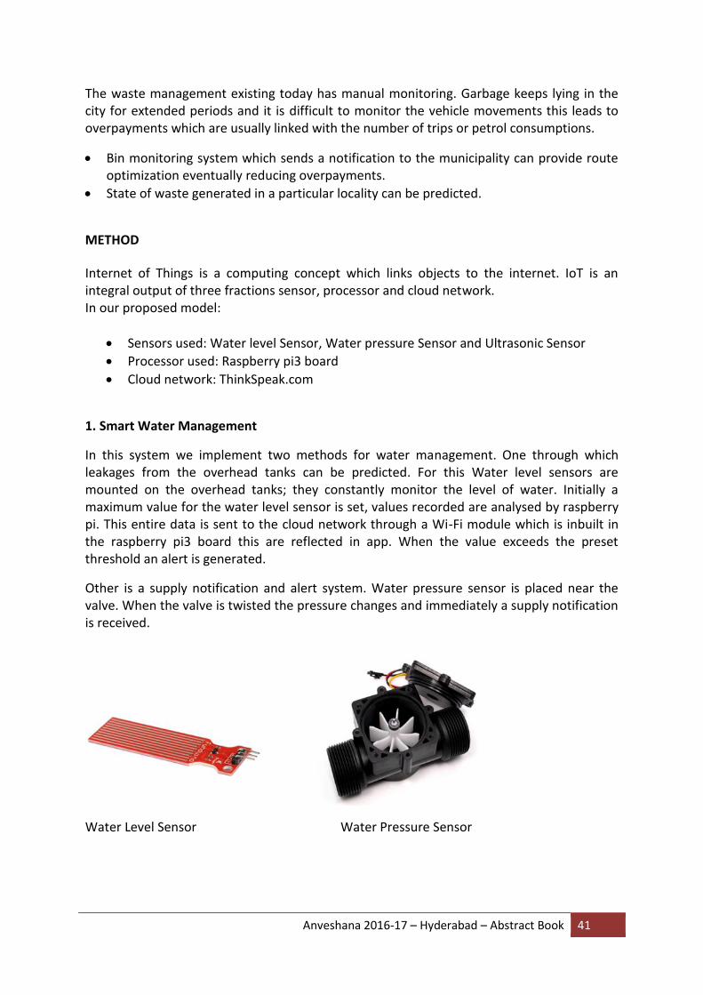
In this system we implement two methods for water management. One through which leakages from the overhead tanks can be predicted. For this Water level sensors are mounted on the overhead tanks; they constantly monitor the level of water. Initially a maximum value for the water level sensor is set, values recorded are analysed by raspberry pi. This entire data is sent to the cloud network through a Wi-Fi module which is inbuilt in the raspberry pi3 board this are reflected in app. When the value exceeds the preset threshold an alert is generated.
Other is a supply notification and alert system. Water pressure sensor is placed near the valve. When the valve is twisted the pressure changes and immediately a supply notification is received.
Water Level Sensor Water Pressure Sensor

Anveshana 2016-17 – Hyderabad – Abstract Book 42
2. Smart Waste Management
This paper proposes a method in which waste management is automated. All the sub-systems work intelligently and in coordination to automate the waste management in the Smart Trash Bins so as to dispose-off the waste as and when required without keeping a continuous eye on the waste bins manually. At the bin level, sensors provide accurate fill level information while randomly-placed solid objects of different shapes are placed in the bin. Given that the bins are installed in the roads or pavements, battery operation is being assumed and strategies for longevity are be devise in the backend, the information from the trash bins is received and stored, along with historical data. At the garbage truck, a notification system is installed in the form of a mobile app. The app assists the city workers by providing a rich-media interface to get information about the service plan and the reported or estimated waste bin fill levels. Ultrasonic sensors can be used for this; initially maximum range for ultrasonic sensor is set with a distance equal to height of trash bin. Values of ultrasonic sensor are read at regular intervals and accordingly percentage of trash bin occupancy is calculated. This data is sent to the cloud through Wi-Fi module connected to processor board. Analysis of data is done at cloud and appropriate routing scheme is defined, which is then reflected in app of waste collection vans.
Ultrasonic Sensor Flow Chart
EXPERIMENT
The embedded part of the model was tested. Sensors play major role, they act as eyes and provide information upon which decisions are taken. A wide variety of sensors are available in the market and the ones that are best suitable and cost efficient are chosen.
The water level sensor contains a series of parallel lines. When water is exposed to these lines it gives the level of water. The sensor was initially tested by interfacing it by a raspberry pi3 board. An ADC (analog-to-digital) converter is required as they are no analog input pins on the board.
Water flow sensor is a digital sensor which we directly interfaced to the Pi board. One end of the sensor was connected to the water source and the other end was outlet. Depending upon the flow of water the sensor was giving variable output values.
For waste management ultrasonic sensor is used. Ultrasonic sensor consists of trigger and echo pins. When triggered it sends out a high frequency sound pulse and records how long it takes for the echo of the sound to reflect back.

Anveshana 2016-17 – Hyderabad – Abstract Book 43
Distance can be calculated as:
Distance = (duration/59.2)
Where duration is the time taken by the echo pin
Maximum range of the ultrasonic sensor is 3m
In the project, distance can be set at the bins, when exceeded it indicates the overflow
Testing of water sensors Testing of ultrasonic sensors
SUMMARY
Water conservation has become a concern globally. Irregular water supplies, water leakage and consumption analysis are few aspects which can be dealt with our proposed solution Sensors with high sensibility and low price sensors, which are easily available in the market. With the growth of the Internet, we can send and receive data everywhere in the world. Moreover, the virtualization of computer and storage, and development of software defined networks facilitate in effective utilization of resources.
Whenever the bin is filled sensors get activated and send a high signal. The message is updated on the cloud database. Location of the bins, area of control and plotting of those bins in the map is shown in the app and the information is collected by the municipality. In this way they don’t need to waste time and effort going to unnecessary routes this also provides safe and hygienic environment. There are several advantages of the proposed system. It provides the real time information on fill level of the overhead tanks and dustbins, there is reduction in cost and resource optimization. Smart water and waste management system is a step forward to make the manual collection and detection of water and wastes automated in nature.
COST - Rs.4,000/-
Anveshana 2016-17 – Hyderabad – Abstract Book 44
10. HIGH SENSITIVE ALCOHOL SENSOR WITH AUTO CAR IGNITION
DISABLE FUNCTION
COLLEGE: TKR COLLEGE OF ENGINEERING AND TECHNOLOGY
GUIDE: A.HARITHA
SCHOOL STUDENTS: M.SWETHA 9Th STD, SRAVANI 9Th STD ZPHS KARMANGHAT
COLLEGE STUDENTS: K.BHAVYA REDDY, K.AKHILA
ABSTRACT
According to a survey done by W.H.O., for almost every 90 seconds, a person is injured in a drunken driving crash. One in three people will be involved in an alcohol-related crash in their lifetime. In drunk and drive cases, people are highly injured or sometimes dead. This is killing not only the driver but also the co passengers travelling on the road at the same time. In order to overcome this problem a project “High Sensitive Alcohol Sensor with Auto car Ignition Disable Function” has been proposed.
This project aims in designing a system which is capable of monitoring alcoholic driving and automatically controlling the ignition system. The system switches OFF the ignition, if the person is alcoholic.
HYPOTHESIS
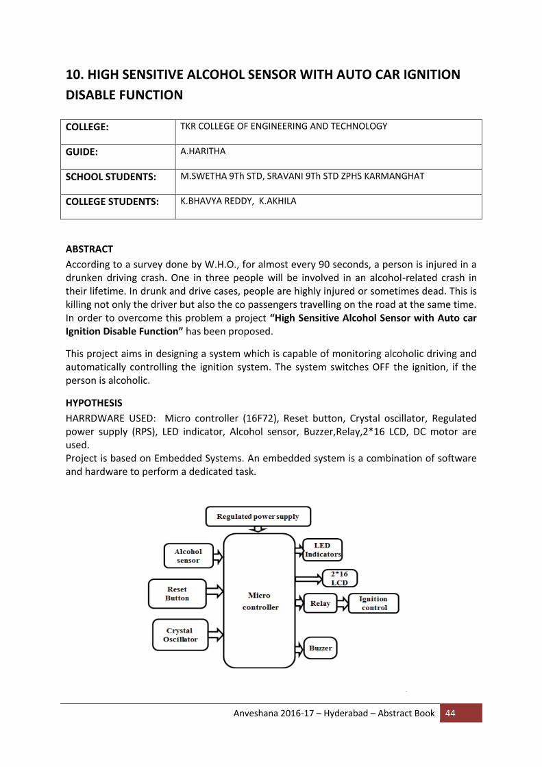
HARRDWARE USED: Micro controller (16F72), Reset button, Crystal oscillator, Regulated power supply (RPS), LED indicator, Alcohol sensor, Buzzer,Relay,2*16 LCD, DC motor are used. Project is based on Embedded Systems. An embedded system is a combination of software and hardware to perform a dedicated task.
Anveshana 2016-17 – Hyderabad – Abstract Book 45
METHOD
The project title “High Sensitive Alcohol sensor with an automatic car ignition disable function” itself indicates that whenever there is any exceeding alcoholic content been detected using alcoholic sensor MQ-3 it will indicate through the buzzer and LCD indications and also automatically disables the car ignition. This project is designed based on a microcontroller which forms the control unit of the project. The project helps in avoiding drunken driving. In this project we are using the alcohol sensor that finds the alcoholic content fed as input to the PIC microcontroller. The microcontroller gets the information regarding the alcohol through the alcohol sensor and alerts when the amount of alcohol reaches a threshold using Buzzer and also deactivates relay and disables the motor driver. The system has a provision of varying the detection.
EXPERIMENT
In this project we are going to receive data from alcohol sensor which is interfaced to microcontroller, converting it into digital form and then controlling the ignition system using relay. Supply is given to the microcontroller and alcohol sensor senses the data in analog format and fed as an input to the inbuilt ADC of PIC microcontroller through port A (0 pin). ADC converts analog input to the digital output. After that the data is stored and then compared to threshold value given in program. If the input value is beyond the limit then microcontroller takes appropriate action by alerting through buzzer then deactivating relay thereby turning the motor off disabling the car ignition and displaying the alcohol percent using LCD which is interfaced to port B of PIC microcontroller. Here the dc motor indicates car ignition
SUMMARY
Tests found that this system is highly effective and a low cost design with long life and is also a simple drive circuit and it is efficient in testing the alcohol percentage of the human beings and if it crosses the threshold value the dc motor will stop working.
It is practically implemented in some cars ex: Nissan N90. This just not only senses at the time of igniting the car but also after few minutes because there is a chance of taking Alcohol at the time of driving so this project is highly useful for the safe and secure driving
COST - INR 1500/-

Anveshana 2016-17 – Hyderabad – Abstract Book 46
11. SOLAR POWERED AUTOMATIC DRAIN CLEANER
COLLEGE: SSJ ENGINEERING COLLEGE
GUIDE: K.V.PURSHOTAM REDDY
SCHOOL STUDENTS: MOHAMMAD ABDUL RAHEMAN, 9TH STD, KANDRENI RAJITHA, 9TH STD Z.P.H.S V.NPALLY
COLLEGE STUDENTS: JULAKANTI SRIDHAR, FARUQ AHAMED
ABSTRACT
In this project we aim to eradicate manual scavenging by bringing automation in waste management system. Many laborers end up losing their life due to choking in attempt to clean the drain. The waste when not removed end up settling and block the drainage systems thereby causing flooding. The machine is designed in such a way that it generates motion by use of solar power. The drainage system cleaner has four major parts which are the solar powered battery, the dc motor, micro-controller and the chain drive with small bucket arrangement all make up for its effective functioning. We have designed our project to use this in efficient way to control the disposal of wastages and with regular filtration of wastages, clearance of gaseous substance are treated separately and monitor the disposal of frequent manner.
HYPOTHESIS
The solar panel converts the light energy into useful electrical energy which is given to the battery of 12v.A Arduino microcontroller acts a brain and controls the system by sensing the signal from sensor and giving output signal to DC motor to turn on/off. The shaft of DC motor is connected to shaft of chain driven mechanism .This chain drive circulates when it receives power from the motor and buckets attached to it lift the garbage and dump it in the bin provided at its rear. The bin has wire mesh which allows water to escape out ensuring only solid waste to remain.
Fig: Layout of Components Used

Anveshana 2016-17 – Hyderabad – Abstract Book 47
METHOD
Roller chains are used in medium and low speed drives at around 600 to 800 feet per minute; however, at higher speeds, around 2,000 to 3,000 feet per minute, V-belts are normally used due to wear and noise issues they don’t find themselves in use.
A roller chains may have a master link, or may require a chain tool for removal and installation. A similar but larger and thus stronger chain is used on most motorcycles although it is sometimes replaced by either a toothed belt or a shaft drive, which offer lower noise level and fewer maintenance requirements
EXPERIMENT
The drainage systems usually over flows in rainy seasons, by the test when water flow is normal the garbage in the system is detected by the PIR sensor which triggers the motor through microcontroller. It rotates the chain drive by which garbage is collected in the bin.
When water flow is more in pipe line the speed of the chain drive is decreased and results in blockage and sensor detection (blindness) which makes the process slow for a while and bucket collects the garbage like plastic, thermocol, sand etc. which decreases the water accumulation.
Fig: Circuit Diagram

Anveshana 2016-17 – Hyderabad – Abstract Book 48
SUMMARY
Automation is a technology concerned with his application of mechanical, electronic and computer based systems to operate and control production. This project may be developed with the full utilization of men, machines, and materials and money. Also we have followed thoroughly the study of time, motion and made our project economical and efficient with the available resources. This system was Designed, Fabricated and also tested successfully. It works Satisfactorily. We hope that this will be done among the most versatile and interchangeable one even in future. Thus we can able to obtain AUTOMATIC DRAIN CLEANING.

Anveshana 2016-17 – Hyderabad – Abstract Book 49
12. BIO PAPER
COLLEGE: MLR INSTITUTE OF TECHNOLOGY
GUIDE: K.SHIVA SHANKAR
SCHOOL STUDENTS: P.VIJAYKUMAR, 9th STD, K.KUMAR CHAVAN 9TH Std, ZPHS MEDCHAL
COLLEGE STUDENTS: G.VAMSHI KRISHNA, HARISH,ADITYA TIWARI
ABSTRACT
Bio-paper is a degradable paper its good when compared with the normal paper made of wood fiber and cotton, which are produced by the deforestation. We had made this bio-paper using the mixture of both plastic and eatable item. Bio-degradable materials are easily available in our day to day life.
The following bio-degradable materials we use in our product are
1) CORN STARCH
This material is used to bind and strengthen the material.
2) PELLETS
These materials are used to strengthen
3) MILK
These is used to bind the whole material
4) OIL
Oil is used to get good mixture
5) EGG
This is used to bind the whole material
6) VEGETABLE WASTE
This is used to bind the material with fibers, which is good in degrading
HYPOTHESIS
It’s the process of recycle->regenerate->reuse.
We use daily items to generate the bio-degradable paper without any damage
Anveshana 2016-17 – Hyderabad – Abstract Book 50
METHOD
We take cornstarch in a bowl. Pellets are added in another bowl. We mix the dry ingredients and non-newtonic fluids. The vegetable waste is added in the mixture. Next milk is added in the required proportion. Then oil is added to mix both the mixture. These are heated up and dried. The paper mixture is ready and ready to form a paper of different size.
EXPERIMENT
We can make the bio paper in different sizes, colors with the same quality and materials. Colour can be added to get different papers.
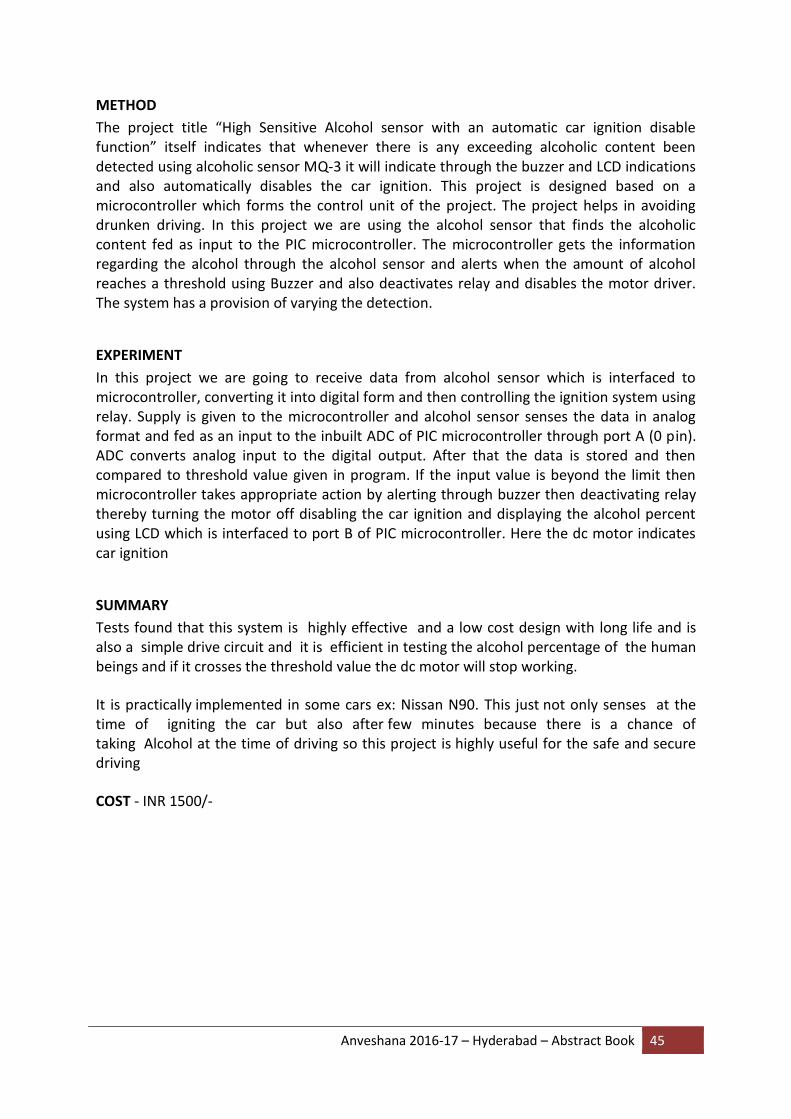
PROJECT PHOTO OUR TEAM
SUMMARY
These papers can be adopted in the market for decreasing the deforestation. We may not know the value of trees now, but one day, we need to pay for fresh air and oxygen if the conditions are worse. Accept the new method, implement in the life for better future.
COST
50 paisa per paper in bulk

Anveshana 2016-17 – Hyderabad – Abstract Book 51
13. SMART SANITATION SYSTEM FOR SUSTAINABLE SANITY
COLLEGE: B V RAJU INSTITUTE OF TECHNOLOGY
GUIDE: P.SHIVA SUBHASHINI
SCHOOL STUDENTS: R.POOJITHA, 9th STD, E.DEEEPAK 9Th STD VISHNU PUBLIC SCHOOL,NARSAPUR
COLLEGE STUDENTS: S.N.S LAHARI,M.SRAVYA,D.NAGA SRUJANA
ABSTRACT
There are a lot of public dustbins present on the road. We often observe that once the dustbins are full, the garbage is thrown outside the bin or near to it. It takes a couple of days until the municipality trucks come by and collect the trash. But during that period, the hygiene of surroundings is disturbed and we also find a lot of animals feeding on the garbage. It might also lead to a lot of health problems. In order to overcome this problem and to contribute to the SWACH BHARATH MISSION, we would like to propose the “Smart Sanitation System for Sustainable Sanity”. The system is equipped with a limit detection sensor attached to each dustbin on the road and when the garbage reaches a certain level, the system communicates with the municipality officials to take measures. It allows the municipal corporation to monitor the sanity of the city in real time. To send the messages cloud storage will be setup with a certain space along with back up facility. By providing this we can overcome the garbage overflow problem and provide a neat and healthy environment.
HYPOTHESIS Over past 15 years the urban population has increased more than 2.5 times, the per capita garbage generation on an average has doubled from 0.25kg/capita to 0.5kg/capita which has the bin filled with waste until the garbage collection is done. Municipal corporations spend Rs.500/- to Rs.1500/- per ton on solid waste management, of which 60-70% of the amount is on collection alone 20% – 30% on transportation. According to World Health Organization 22 types of diseases can be prevented or controlled by improving solid waste management in India. Due to this increase in the statistics,a need for garbage detection has been observed. It also reduces the time and effort of the corporations along with providing a better environment.
BLOCK DIAGRAM
METHOD
Initially, an ultrasonic sensor is placed senses the level of garbage in the dustbin. NODE MCU 12E gets the information from the sensor and the data is sent to the open cloud, Thingspeak. Using this, real time monitoring of the level of garbage in the dustbin can be
Anveshana 2016-17 – Hyderabad – Abstract Book 52
done. This facility can be utilized by the municipal corporations to understand the garbage levels in the dustbin and accommodate collection of the garbage to a certain area accordingly. Using this method, the problem of overflow of waste in the dustbin can be solved.
EXPERIMENT The ultrasonic sensor is placed on top of the dustbin. The ultrasonic sensor has a transmitter as well as a receiver. The transmitter sends a sound wave, which reflects back to the receiver of the sensor through which the duration can be calculated. The NODE MCU 12E takes the data from the sensor and sends the data to Thingspeak. In Thingspeak, the channel is created through which real time monitoring of the level of waste can be done.
SUMMARY
As a result, the garbage levels can be detected using certain components such as NODE MCU 12E, ultrasonic sensor and a rechargeable battery along with an open cloud “Thingspeak”. This helps the Municipal Corporation to understand the levels of dustbin according to which they can regulate the collection process of garbage. Using this, overflow of garbage can also be prevented which helps in improving the quality of the environment and also the general health conditions of the neighborhood. This also supports the government initiative of “SWACHH BHARATH MISSION”.
COST
The cost of the product is, INR 2000.

Anveshana 2016-17 – Hyderabad – Abstract Book 53
14. AUTOMATIC CULTIVATION SYSTEM USING MICROCONTROLLER
COLLEGE: ACE ENGINEERING COLLEGE
GUIDE: B. GIRI RAJU
SCHOOL STUDENTS: NUKALA SANDEEP, MARISHETTI HEMALATHA
COLLEGE STUDENTS: VVS POTHAN T, PALLA DIVYA LAKSHMI
ABSTRACT
Watering the plant is the most important cultural practice and one of the labour intensive tasks in daily greenhouse operation. Knowing when and how much to water are important aspects of irrigation. Watering systems ease the burden of getting water to plants when they need it. To make the works easy, the automatic plant watering system is implemented. The entire system is controlled using AT89S52 microcontroller’s which is programmed as giving the interrupt signal to the sprinkler. Labour-saving technology is a key issue in cultivation. Microcontroller based automatic cultivation system allows a simple low cost and monitoring overhead method for cultivating the crops automatically.
The main objective of this product is to develop a microcontroller based system to cultivate the plant automatically. This system also supports water management decision, which determines the controlling time for the process. Another objective of the project is to send a short message service (SMS) to farmer regarding Nutrients level in the Fertilizer tank.
HYPOTHESIS
The module works with two operating modes. Where the first one is Manual Mode & the other is Automatic Mode. In the Manual Mode, the functioning of the drivers in the module is controlled by the user manually. Whereas in the Automatic mode, the entire module functioning is controlled by the microcontroller without any interference of the user, except while installing and initializing the Product at site.
METHOD
Cultivation system uses Solenoid-valves to turn irrigation ON and OFF. These valves may be easily automated by using controllers. Automating farm or nursery irrigation allows farmers to apply the right amount of water at the right time, regardless of the availability of labour to turn valves on and off. In addition, farmers using automation equipment are able to reduce runoff from over watering saturated soils, avoid irrigating at the wrong time of day, which will improve crop performance by ensuring adequate water and nutrients when needed.
The microcontroller is the heart of the proposed embedded system. It constantly monitors the water levels and verifies them with the predefined threshold values and checks the condition for minimum level and maximum level, and correspondingly the relay is made ON or OFF to fill the tanks with water.
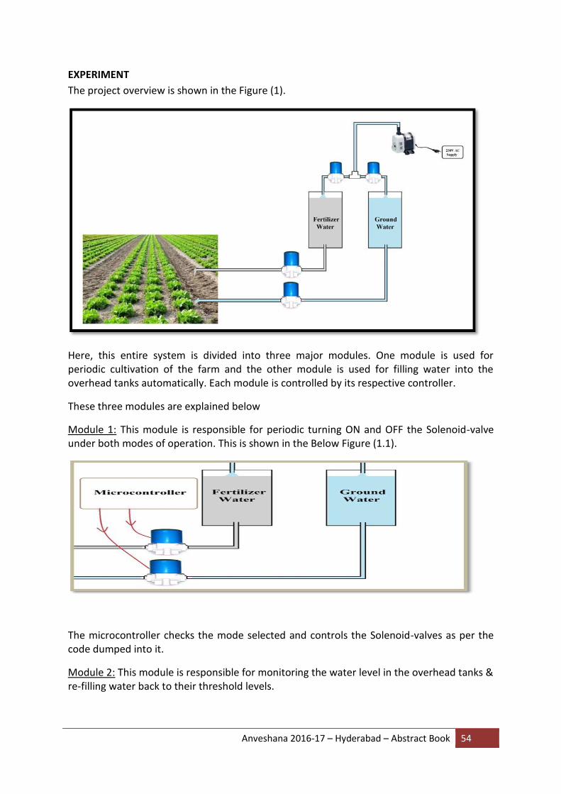
Anveshana 2016-17 – Hyderabad – Abstract Book 54
EXPERIMENT
The project overview is shown in the Figure (1).
Here, this entire system is divided into three major modules. One module is used for periodic cultivation of the farm and the other module is used for filling water into the overhead tanks automatically. Each module is controlled by its respective controller.
These three modules are explained below
Module 1: This module is responsible for periodic turning ON and OFF the Solenoid-valve under both modes of operation. This is shown in the Below Figure (1.1).
The microcontroller checks the mode selected and controls the Solenoid-valves as per the code dumped into it.
Module 2: This module is responsible for monitoring the water level in the overhead tanks & re-filling water back to their threshold levels.

Anveshana 2016-17 – Hyderabad – Abstract Book 55
This microcontroller takes the input from the water tanks & depending on the threshold value, it pumps water into the tanks. The additional work that is done by this module is, it sends a SMS alert to the user when the nutrition gradient level in the fertilizer water tank gets diluted.
Module 3: This module is responsible for providing the security to the farm and the system. It alerts the user, whenever the humans approach nearby the farming field or towards the installed system.
SUMMARY
The system is purely automated for the purpose of cultivation in order to harvest good quality crop.
This product is best suitable for using it at Vegetable fields and Nursery plants, where the soil must be fertile all the time. And this can be achieved by supplying the nutrition to the farm from the Fertilizer tank at periodic time-intervals.
The product can also be provided with Power-Backup system by using PV cells and power storage banks.
COST - Rs. 2,500.00/-
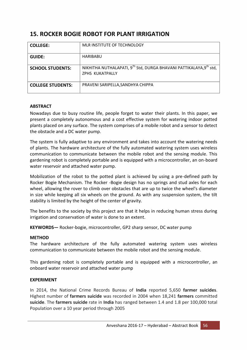
Anveshana 2016-17 – Hyderabad – Abstract Book 56
15. ROCKER BOGIE ROBOT FOR PLANT IRRIGATION
COLLEGE: MLR INSTITUTE OF TECHNOLOGY
GUIDE: HARIBABU
SCHOOL STUDENTS: NIKHITHA NUTHALAPATI, 9Th Std, DURGA BHAVANI PATTIKALAYA,9th std, ZPHS KUKATPALLY
COLLEGE STUDENTS: PRAVENI SARIPELLA,SANDHYA CHIPPA
ABSTRACT
Nowadays due to busy routine life, people forget to water their plants. In this paper, we present a completely autonomous and a cost effective system for watering indoor potted plants placed on any surface. The system comprises of a mobile robot and a sensor to detect the obstacle and a DC water pump.
The system is fully adaptive to any environment and takes into account the watering needs of plants. The hardware architecture of the fully automated watering system uses wireless communication to communicate between the mobile robot and the sensing module. This gardening robot is completely portable and is equipped with a microcontroller, an on-board water reservoir and attached water pump.
Mobilization of the robot to the potted plant is achieved by using a pre-defined path by Rocker Bogie Mechanism. The Rocker -Bogie design has no springs and stud axles for each wheel, allowing the rover to climb over obstacles that are up to twice the wheel's diameter in size while keeping all six wheels on the ground. As with any suspension system, the tilt stability is limited by the height of the center of gravity.
The benefits to the society by this project are that it helps in reducing human stress during irrigation and conservation of water is done to an extent.
KEYWORDS— Rocker-bogie, microcontroller, GP2 sharp sensor, DC water pump
METHOD The hardware architecture of the fully automated watering system uses wireless communication to communicate between the mobile robot and the sensing module. This gardening robot is completely portable and is equipped with a microcontroller, an onboard water reservoir and attached water pump
EXPERIMENT
In 2014, the National Crime Records Bureau of India reported 5,650 farmer suicides. Highest number of farmers suicide was recorded in 2004 when 18,241 farmers committed suicide. The farmers suicide rate in India has ranged between 1.4 and 1.8 per 100,000 total Population over a 10 year period through 2005
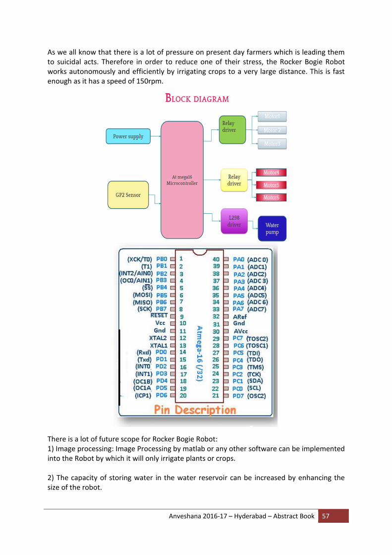
Anveshana 2016-17 – Hyderabad – Abstract Book 57
As we all know that there is a lot of pressure on present day farmers which is leading them to suicidal acts. Therefore in order to reduce one of their stress, the Rocker Bogie Robot works autonomously and efficiently by irrigating crops to a very large distance. This is fast enough as it has a speed of 150rpm.
There is a lot of future scope for Rocker Bogie Robot: 1) Image processing: Image Processing by matlab or any other software can be implemented into the Robot by which it will only irrigate plants or crops. 2) The capacity of storing water in the water reservoir can be increased by enhancing the size of the robot.

Anveshana 2016-17 – Hyderabad – Abstract Book 58
3) A Vernier Soil Moisture Sensor can be used to monitor the moisture level of your plant’s soil. The soil will be considered “too dry” when the moisture level falls below 20%, and sufficiently “wet” when the moisture level rises above 28% and then irrigate the plants autonomously.
SUMMARY
In current scenario there are solutions as well as number of problems. The unique feature about Rocker Bogie Robot is the Rocker Bogie design. It can run on hard, bumpy surface without any effort, also it is environment adaptive i.e., though it is sunny or rainy or windy it does not get affected.
It weighs 4 kgs, 59 cms long, 29 cms wide and 44 cms, in height,
The distinctive feature about Rocker Bogie Robot is that it contains a water reservoir and is autonomous. Power supplied to it is 12 volts where a rechargeable battery of 12 volts is used.
COST
Overall cost of Rocker Bogie for manufacturing and the components is 2000 rupees.

Anveshana 2016-17 – Hyderabad – Abstract Book 59
16. PELTIER AIR COOLER
COLLEGE: VELAGAPUDI RAMAKRISHNA SIDDHARTHA ENGINEERING COLLEGE
GUIDE: M.GAYATHRI
SCHOOL STUDENTS: B.AKHIL BABU 9ThSTD, S.AKASH REDDY 9Th STD, SRI NAVA BHARAT HIGH SCHOOL,VIJAYAWADA
COLLEGE STUDENTS: M.JITHENDRA , VIJAY SAMBHASIVA RAO
ABSTRACT The solution made by man to make himself cool from the heat is air conditioner. But unfortunately on the other hand it is leading to global warming as the coolant used in air conditioner liberates chlorofluorocarbons (CFCs) .This paper gives the better solution which
is free from liberating CFC’s and other gases which causes global warming.
PELTIER EFFECT The thermoelectric effect is the direct conversion of temperature differences to electric voltage and vice versa. A thermoelectric device creates voltage when there is a different temperature on each side. Conversely, when a voltage is applied to it, it creates a temperature difference. At the atomic scale, an applied temperature gradient causes charge carriers in the material to diffuse from the hot side to the cold side.
This effect can be used to generate electricity, measure temperature or change the temperature of objects. Because the direction of heating and cooling is determined by the polarity of the applied voltage, thermoelectric devices can be used as temperature controllers.
The term "thermoelectric effect" encompasses three separately identified effects: the Seebeck effect, Peltier effect, and Thomson effect. Textbooks may refer to it as the Peltier–Seebeck effect.
WORKING
Peltier air cooler is made of peltier module which is made up of semiconductor (doped Bismuth telluride) which works on peltier effect. The DC power source i.e. SMPS supplies the power to the peltier module. Due to the flow of current in it cold and hot junctions are formed according to the peltier effect. The cold junction here acts as a indoor unit of cooler and hot junctions acts as an outdoor unit of cooler
The main requirements by an individual regarding appliance is its cost ,efficiency and the mainly it should be Eco friendly which we do not consider but times has come to use appliance which are Eco friendly to decrease global warming .The peltier air cooler is free from CFC’S which is Eco friendly .It is compact in size. It works efficiently below ambient temperature and has fast dynamic response .As Brushless motor consumes less power compare to regular motor it is used here.
COMPONENTS
1. Peltier modules
Anveshana 2016-17 – Hyderabad – Abstract Book 60
2. Atmega 328p MU
3. Brushless motor 900kv
4. ESC 30A
5. Variable resistor 100k
6. Wooden box 300x300mm
7. Copper sheet
CONCLUSION
The main aim of this project is to decrease the draw backs of regular air cooler and make a portable air cooler at minimum cost.
Anveshana 2016-17 – Hyderabad – Abstract Book 61
17. REDUCTION OF ACCIDENTS BY ALCOHOL DETECTOR IN VEHICLES
COLLEGE: BHOJ REDDY COLLEGE OF ENGINEERING FOR WOMEN
GUIDE: ASHA KIRAN MAI
SCHOOL STUDENTS: B KEERTHI 9th STD, M SHIRISHA 9th STD, M H GUPTA HIGH SCHOOL
COLLEGE STUDENTS: P HEMA, M ANUSHA, G NIHARIKA, K PALLAVI
ABSTRACT:
These days drunken drivers have increased enormously. Due to these people, many accidents are taking place. The main reason for driving drunk is that the police are not able to check each and every vehicle and if they catch anyone the police can be easily bribed. So there is a need for an effective system to check the drunken drivers. This alcohol detection system use to check whether alcohol was consumed by driver recently or not. This system consists of alcohol sensor, comparator, relay and voltage regulator. The DC power supply of 12V is regulated to 5V using regulator. This 5V is given to alcohol module, relay and motor. When alcohol is brought near to the alcohol sensor, the sensor will detect the alcohol and the alcohol module gives the signal to the relay, then the relay disconnects the motor from the power supply. Hence the vehicle gets stopped.
HYPOTHESIS:
The system which exists is that these days drunken drivers have increased enormously. Due to these people, many accidents are taking place. This may lead to the lost of many lives. So there is a need for an effective system to check the drunken drivers. At present, there is no such system to stop the vehicle when the alcohol is detected.
To overcome this disadvantage of the above existing system, there is a need for an
advanced technology which reduces the occurrence of accidents caused by the consumption
of alcohols. So, there is a need for alcohol detector which can bring a change in the existing
system. Hence this system helps people a lot.
METHOD:
The power supply 5 volts are given to the heating coils, input pins of alcohol sensor and non-
inverting terminal of comparator. When the alcohol is sensed by the alcohol sensor,
conduction starts in the sensor and it gives analog output. This analog output is given to the
inverting terminal of the comparator.
The comparator compares the inputs of both non-inverting and inverting terminals. If the
voltage at inverting terminal, then the output of the comparator is drawn down to GND. is
greater than the voltage at the non-inverting terminal, then the output of comparator will

Anveshana 2016-17 – Hyderabad – Abstract Book 62
be drawn up to Vcc. If the voltage at inverting terminal is less than the voltage at non-
inverting
The DC power supply of 12 volts is regulated to 5 volts using 7805 Regulator. This 5 volts is given to alcohol module, relay and motor. When alcohol is brought near to the alcohol sensor, the sensor will detect the alcohol and the alcohol module gives the signal to the relay, then the relay disconnects the motor from the power supply. Hence the motor gets stopped.
EXPERIMENT:
Testing and results:
Case 1: kit is tested without alcohol in the environment
In this case when the switch is ON, motor positive terminal is connected to the positive terminal of the supply. As there is no alcohol, the digital output of alcohol module becomes zero volts and the transistor acts as an open switch. Now the motor negative terminal is connected to the ground and thus the motor starts rotating. Hence the ignition system is enabled.
Case 2: kit is tested with alcohol in the environment
In this case the alcohol is brought near to the alcohol sensor. Hence the sensor detects the alcohol. As a result the digital output of the alcohol module becomes 5 volts and the transistor acts as a closed switch. Now the motor negative terminal is disconnected from the ground and thus the motor stops rotating. Hence the ignition system is disabled.
SUMMARY:
The hardware for ”REDUCTION OF ACCIDENTS BY ALCOHOL DETECTOR IN VEHICLES” constructed and tested successfully. It has been developed by the features of all hardware components used. Presence of every module has been reasoned out and placed carefully thus contributing to the best working of the unit. This project will provide full safety for the lives of the people who are drunken drivers. It is most advantageous as compared to other alternatives available for providing safety since it is an automatic system, which disables the ignition of the system by sensing the alcohol. And this can be used by any vehicle, where safety plays an important role with low cost and many advantages. For the developing countries like India this will be more helpful. It plays a crucial role in economic aspects. The system is simple, secure, reliable and fast. It can be installed in any vehicle which reduces a lot of accidents.
So, this project will help people a lot as it disables the ignition of the vehicle. We will still develop and extend our project to maximum level for the safety of the people and extend the service with good response.
COST : Rs.1200
Anveshana 2016-17 – Hyderabad – Abstract Book 63
18. TECHNOLOGICAL AID FOR DYSCALCULIA USING OPEN CV AND
MINTER SYSTEM
COLLEGE: G NARAYANAMMA INSTITUTE OF TECHNOLOGY AND SCIENCE
GUIDE: Dr. N KALYANI
SCHOOL STUDENTS: CHANDRASHEKAR.N. 9th STD, DHARANI.S, 9TH STD G.PULLA REDDY HIGH SCHOOL
COLLEGE STUDENTS: SATYA NARAPARAJU,PRANAVI JALAPATI
ABSTRACT
Dyscalculia is a brain based mathematical disorder which is associated with difficulties in understanding numbers and mathematical concepts. This disorder can be illustrated as cases where either the students know what to do but not why to do, or the students understand the logic but fail to implement it, or at the very elementary level, the students might be confused with the numbers itself. The most common problem is with “number sense”. This is an intuitive understanding of how numbers work, and how to compare and estimate quantities on a number line. Number blindness is one reason many kids have trouble connecting numbers to the real world. Kids suffering with this condition cannot cope up with the real world transactions essential for survival. Consider a scenario when a kid facing mathematical difficulties approaches a grocery store. The kid knows what to purchase but not how much to spend for it. The shopkeeper can manipulate him to pay extra money.
Dyscalculia being a learning disability, most of the support given is in the form of tools to aid learning or help them understand the things better. But the scope of these tools is limited. A tool designed of one case cannot fit the other. Also, these methodologies do not prepare the students for the real world. The motto of this project is to design a system that makes a person independent irrespective of his learning disabilities.
HYPOTHESIS This aid addresses the problem where the kid does not have to forcefully learn something not meant for him yet can confidently involve in day to day transactions with assurance and safety. The idea is to procure only the required amount needed for the payment in an authorized and authentic manner. The child has the access to a device which can be referred as a minter which is the heart of the project and automates the shopping system.

Anveshana 2016-17 – Hyderabad – Abstract Book 64
METHOD It is connected to an optical image scanner which uses OPEN CV software to identify the bar-coded objects. When an object or a barcode is scanned, it is recognized using the dataset of the OPEN CV software, the barcode information is sent to the guardians or parents. Further, the parent can register set of items that the child can purchase without authentication. Such products can be directly bought and taken home. This way, the expenditure can be tracked as well. This helps the working parents to monitor their children as well as give them the freedom to experience the real world.
Consider the Case study, where the child goes to a store. When he identifies something, he immediately scans the barcode to notify the parent about the product. Further, the device provides the list of items he can buy. Every child is identified with an identity card .When the child's identity card is scanned the money is automatically transacted. This cashless transaction improves the waiting time in the queue, as well as eradicating the hassle with the money managing. It helps the children with number blindness identifying the numbers itself was their problem at the first place.
Process flow
1. The item to be purchased is chosen.
2. The barcode is scanned for the packed items and the rest can be chosen using the NFC
tags associated with it.
3. The data of the scanned products is verified in the data base to validate the access
control. Lack of authorization triggers a push notification to the guardian.
4. Once the list is authorized, the transaction can be processed either by using the CoD
option of the NFC payment methodology.

Anveshana 2016-17 – Hyderabad – Abstract Book 65
Arduino Arduino is an open-source electronics platform based on easy-to-use hardware and software. Arduino boards can read inputs - light on a sensor, a finger on a button, or a Twitter message - and turn it into an output - activating a motor, turning on an LED, publishing something online. It can be programmed using the Arduino programming language. Arduino/Genuino Uno is a microcontroller board based on the ATmega328P (datasheet). It has 14 digital input/output pins (of which 6 can be used as PWM outputs), 6 analog inputs, a 16 MHz quartz crystal, a USB connection, a power jack, an ICSP header and a reset button. It contains everything needed to support the microcontroller; simply connect it to a computer with a USB cable or power it with an AC-to-DC adapter or battery to get started.
OpenCV
OpenCV (Open Source Computer Vision Library) is an open source computer vision and machine learning software library. OpenCV was built to provide a common infrastructure for computer vision applications and to accelerate the use of machine perception in the commercial products. Being a BSD-licensed product, OpenCV makes it easy for businesses to utilize and modify the code. It has C++, C, Python, Java and MATLAB interfaces and supports Windows, Linux, Android and Mac OS. OpenCV leans mostly towards real-time vision applications and takes advantage of MMX and SSE instructions when available. A full-featured CUDA and OpenCL interfaces are being actively developed right now. There are over 500 algorithms and about 10 times as many functions that compose or support those algorithms. OpenCV is written natively in C++ and has a template interface that works seamlessly with STL containers.
Aurdino OpenCV Python
Python Python is an easy to learn, powerful programming language. It has efficient high-level data structures and a simple but effective approach to object-oriented programming. Python’s elegant syntax and dynamic typing, together with its interpreted nature, make it an ideal language for scripting and rapid application development in many areas on most platforms. The Python interpreter is easily extended with new functions and data types implemented in C or C++ (or other languages callable from C). Python is also suitable as an extension language for customizable applications.
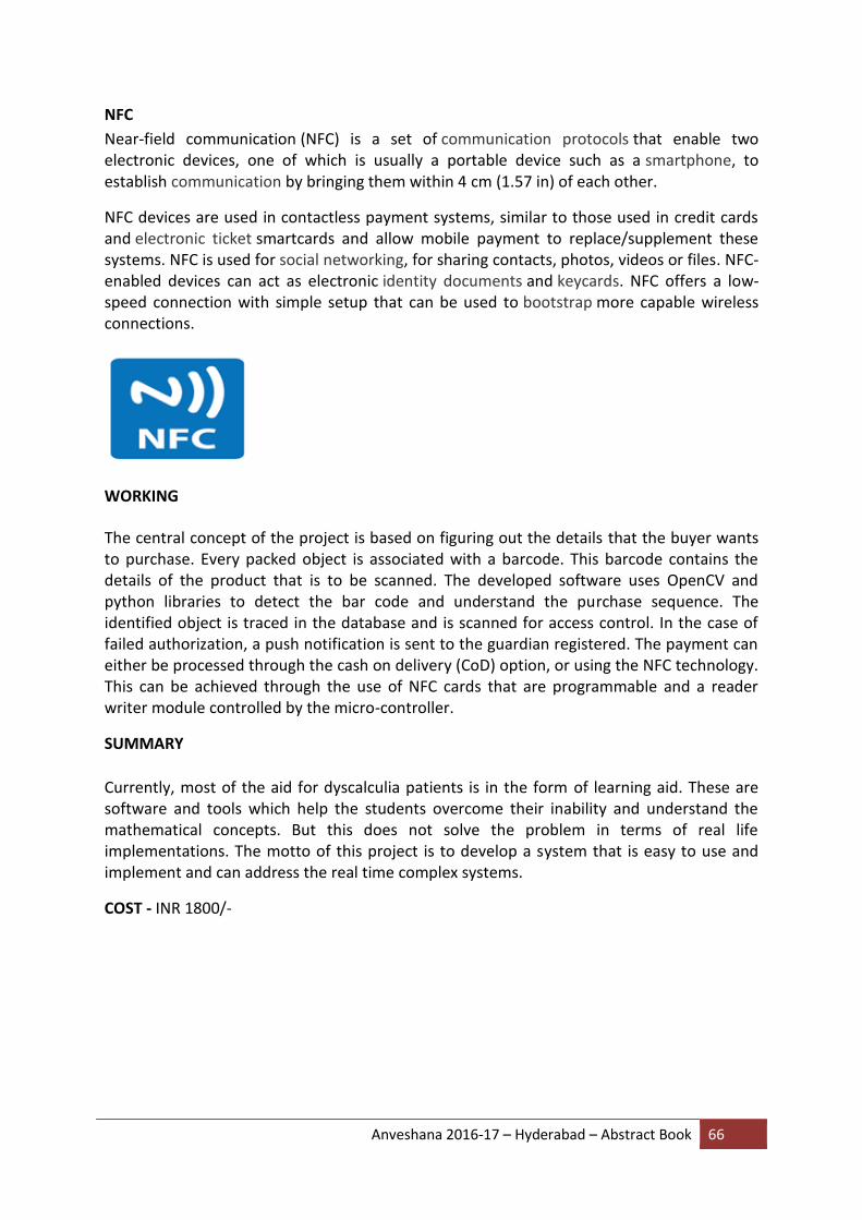
Anveshana 2016-17 – Hyderabad – Abstract Book 66
NFC
Near-field communication (NFC) is a set of communication protocols that enable two electronic devices, one of which is usually a portable device such as a smartphone, to establish communication by bringing them within 4 cm (1.57 in) of each other.
NFC devices are used in contactless payment systems, similar to those used in credit cards and electronic ticket smartcards and allow mobile payment to replace/supplement these systems. NFC is used for social networking, for sharing contacts, photos, videos or files. NFC-enabled devices can act as electronic identity documents and keycards. NFC offers a low-speed connection with simple setup that can be used to bootstrap more capable wireless connections.
WORKING
The central concept of the project is based on figuring out the details that the buyer wants to purchase. Every packed object is associated with a barcode. This barcode contains the details of the product that is to be scanned. The developed software uses OpenCV and python libraries to detect the bar code and understand the purchase sequence. The identified object is traced in the database and is scanned for access control. In the case of failed authorization, a push notification is sent to the guardian registered. The payment can either be processed through the cash on delivery (CoD) option, or using the NFC technology. This can be achieved through the use of NFC cards that are programmable and a reader writer module controlled by the micro-controller.
SUMMARY
Currently, most of the aid for dyscalculia patients is in the form of learning aid. These are software and tools which help the students overcome their inability and understand the mathematical concepts. But this does not solve the problem in terms of real life implementations. The motto of this project is to develop a system that is easy to use and implement and can address the real time complex systems.
COST - INR 1800/-
Anveshana 2016-17 – Hyderabad – Abstract Book 67
19. E-DUSTBIN
COLLEGE: AVANTHI INSTITUTE OF ENGINEERING AND TECHNOLOGY
GUIDE: S.MAHESH REDDY
SCHOOL STUDENTS: NARASIMHA 10TH Std, SHIVA KUMAR 10TH Std, ZPHS, VANASTHALIPURAM
COLLEGE STUDENTS: V.SAHITHI, G.ARUNDHATHI
ABSTRACT
As a developing nation and as the second most populous country in the world we in India face unique problems that require unique solutions. One such problem is that of waste management. As of now there are traditional waste management systems like periodic and routine clearing by the various civic bodies like the municipal corporation. But even though these routine maintenances is carried out we often come across overflowing garbage bins from which the garbage spills on to the streets. This happens because as of now there is no system in place that can monitor the garbage bins and indicate the same to the corporation.
A big challenge in the urban cities is solid waste management. Hence, smart dustbin is a system which can eradicate this problem or at least reduce it to the minimum level. Our present Prime Minister of India, Sri Narendra Modiji has introduced the concept of implementing 100 smart cities in India. “Swachh Bharat Abhiyan” was initiated to ensure a clean environment.
According to the UN, between now and 2025, the world population will increase by 20% to reach 8 billion inhabitants (from 6.5 today).With this increase in population, the responsibilities towards waste management also increases. Our waste administration frameworks and our economic situations, even taking care of business, are unequipped for taking care of the developing measures of waste universally. So unless a new paradigm of global cooperation and governance is adopted, a tidal wave of uncontrolled dumpsites will be the principal waste management method, especially in Asia.
On the west coast of America, San Francisco leads the way with a landfill disposal diversion rate of 72% and the city has set itself a target of zero waste to landfill by 2020.
This paper gives us one of the most efficient ways to keep our environment clean and green.
Dustbin is a common means and a basic need everywhere. It is observed that often the garbage get collected due to irregular removal of garbage present in the dustbin. In the proposed paper, a new model for the municipal dustbins which intimates the center of municipality for immediate cleaning of dustbin has been proposed.
HYPOTHESIS
Bad waste management can easily result in air pollution and soil contamination. They have an adverse effect on human health. It is learnt from the primary survey done in Guwahati, a city in Assam that garbage accumulation causes 41% of the air pollution. They cause air pollution which generally leads to various respiratory problems like COPD, asthma etc.

Anveshana 2016-17 – Hyderabad – Abstract Book 68
Breeding of mosquitoes and houseflies occur mainly in garbage which are a major cause for various diseases like malaria, dengue, chikenguniya etc.
This also causes headache, nauseous sensation and increase in the stress level. A city with poor sanitation and smelly environment can never be a healthy place to live in. There are about 235 million people currently suffering from asthma for which foul smelling of garbage is also a vital reason. Almost 90% of chronic obstructive pulmonary disease (COPD) occurs in low and middle income countries which are caused by foul smelling. More than 3 million people died of COPD in 2005.Improper management of garbage is identified to be one of the major causes for 22 human diseases causing premature death every year. Implementation of this smart dustbin can prevent lumping of the garbage for a longer period of time thereby preventing the widespread of diseases to a great extent and promising a clean environment in the city.
METHOD
In this project we use a self - sustained maintenance free system that uses a combination of GSM module, IR sensors, PIC microcontroller, LCD display, RPS (regulated power supply), SOLAR panel with rechargeable battery.
1. RPS (REGULATED POWER SUPPLY): This is used to convert AC (alternating current) into DC (constant direct current).
2. SENSORS: A sensor is a device that measures a physical quantity and converts into a signal which can be read by an instrument. Here we consists a white LED and a black LED which works based on INFRARRED RAYS .white led acts as transmitter and black led acts as receiver.
3. LCD DISPLAY: This is used to display the text or words with low information content.
4. GSM MODULE: This data is further send to the garbage analyser as instant message using GSM module. Every message which is received at the garbage analyser end is being saved as data which is further used for the process of analysis and predictive modelling. The data received at real time is used by the application interface for better viewing of the filled level. We use "SIM900" GSM MODULE. This works under 900 MHZ frequencies.
5. PIC MICRO-CONTROLLER: This project makes use of an onboard computer, which is commonly termed as micro controller. It acts as heart of the project. This onboard computer can efficiently communicate with the output and input modules which are being used. The controller is provided with some internal memory to hold the code. This memory is used to dump some set of assembly instructions into the controller. And the functioning of the controller is dependent on these assembly instructions.
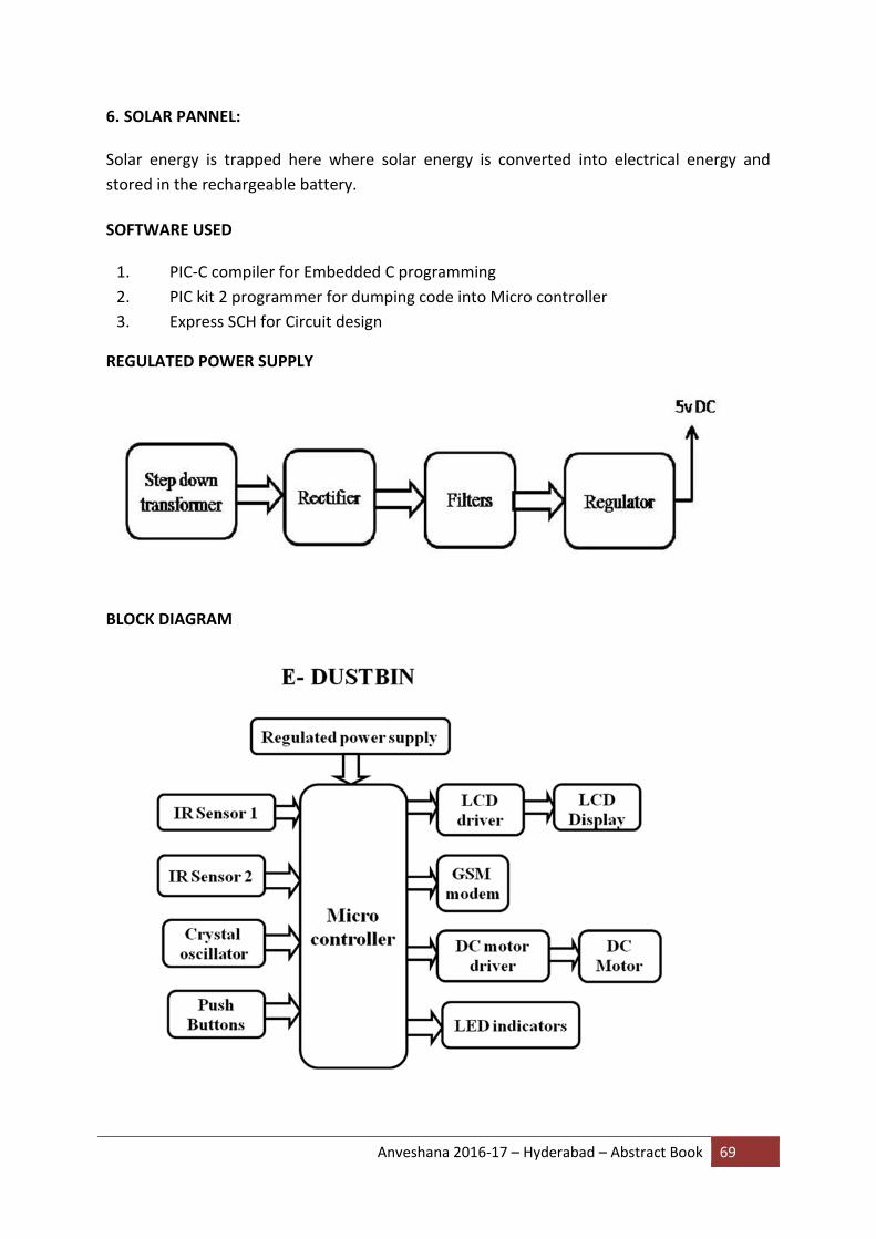
Anveshana 2016-17 – Hyderabad – Abstract Book 69
6. SOLAR PANNEL: Solar energy is trapped here where solar energy is converted into electrical energy and
stored in the rechargeable battery.
SOFTWARE USED
1. PIC-C compiler for Embedded C programming
2. PIC kit 2 programmer for dumping code into Micro controller
3. Express SCH for Circuit design
REGULATED POWER SUPPLY
BLOCK DIAGRAM

Anveshana 2016-17 – Hyderabad – Abstract Book 70
EXPERIMENT
In this project we place two sensors on either side on top of the dustbin. When the dustbin is filled with garbage, the sensors get activates and gives the information to PIC microcontroller. Here sensor module consisting of comparator and white led emits IR rays, when the garbage is filled the IR rays are reflected back towards black LED. Then the comparator compares two voltage levels and sends the information to micro controller
PIC microcontroller is programmed with municipal corporation authorized mobile number .when the information from sensors is sent to this pic microcontroller. This sends the information to the authorized person using GSM module.
GSM module consists of antenna and sim slot, in that we place a sim card having message and main balance. This helps to communicate with the municipal cooperation by auto dialing and message alert at given intervals of time.
The information that dustbin filled in so and so street is sent to the municipal corporation.
This project helps in waste management in INDIA by ensuring hygiene across the country
SUMMARY
Various features such as durability, affordability, prevention against damage and maintenance issues are addressed when these smart dustbins are designed. This Smart Dustbin can contribute a lot towards clean and hygienic environment in building a smart city.
But since the technology is new in India, proper awareness should be created among the public before it is implemented on a large scale. Otherwise, sensitive devices like sensors might be damaged due to rough action of the users.
ADVANTAGES
1. It is low cost.
2. Easy to implement.
3. Flexible to operate.
4. Low power consumption.
COST - RS.2000/- ONLY
Anveshana 2016-17 – Hyderabad – Abstract Book 71
20. QUAD WHEELED OMNI DIRECTIONAL ROBOT
COLLEGE: MLR INSTITUTE OF TECHNOLOGY
GUIDE: E. AMARESHWAR
SCHOOL STUDENTS: K. SAI MADHAV, 9th STD, SINDHUJA 9Th STD, ZPHS KUKATPALLY
COLLEGE STUDENTS: MANDALAPU LAVANYA & BELKERI SAI PRAKASH
ABSTRACT
The goal of this design is to build an easy to assemble Omni-wheeled robot which allows translational movement along any desired path can be combined with a rotation, so that the robot arrives to its destination at the correct angle.
The invention of the wheel literally revolutionized the history of man. Thanks to it, it was possible to create forms of transportation, invent new industrial and architectural machinery. The wheel is so perfect that no one would think to improve it but recently some special, revolutionary wheels have been invented. These wheels are called “Omni-directional” and essentially consist of a set of normal wheels assembled in such a way as to allow new kind of movements.
With Omni-directional wheels is possible to create moving platforms with only three or four wheels, with evident savings respect to the version seen before. However, using wheels of this kind you lose the ability to exploit full motor torque and, in the case of rough surfaces, these are unable to guarantee an exact forward direction.
Omni-directional wheels can be used to create simple four wheels platforms and small robots. A platform employing three Omni wheels in a triangular configuration is generally called Kiwi Drive. They are often used in small autonomous robots in intelligent robots research in the academia.
HYPOTHESIS Omni-directional wheels have become popular for mobile robots, because they allow them to drive on a straight path from a given location on the floor to another without having to rotate first. Moreover, translational movement along any desired path can be combined with a rotation, so that the robot arrives to its destination at the correct angle.
Omni-directional wheels are unique as they are able to roll freely in two directions .It can ether roll like a normal wheel or roll laterally using the wheels along its circumference. Omni-direction wheels allow a robot to convert from a non-Holonomic to a Holonomic robot. A non-Holonomic robot that uses normal wheels has only 2 out of 3 controllable degrees-of-freedom which are, moving forward, backwards and rotation. Not being able to move sideways makes a robot slower and less efficient in reaching its given goal. The Holonomic Omni-directional wheels are able to overcome this problem, as it is highly maneuverable. Unlike normal non-Holonomic robot, the Holonomic Omni-directional robot
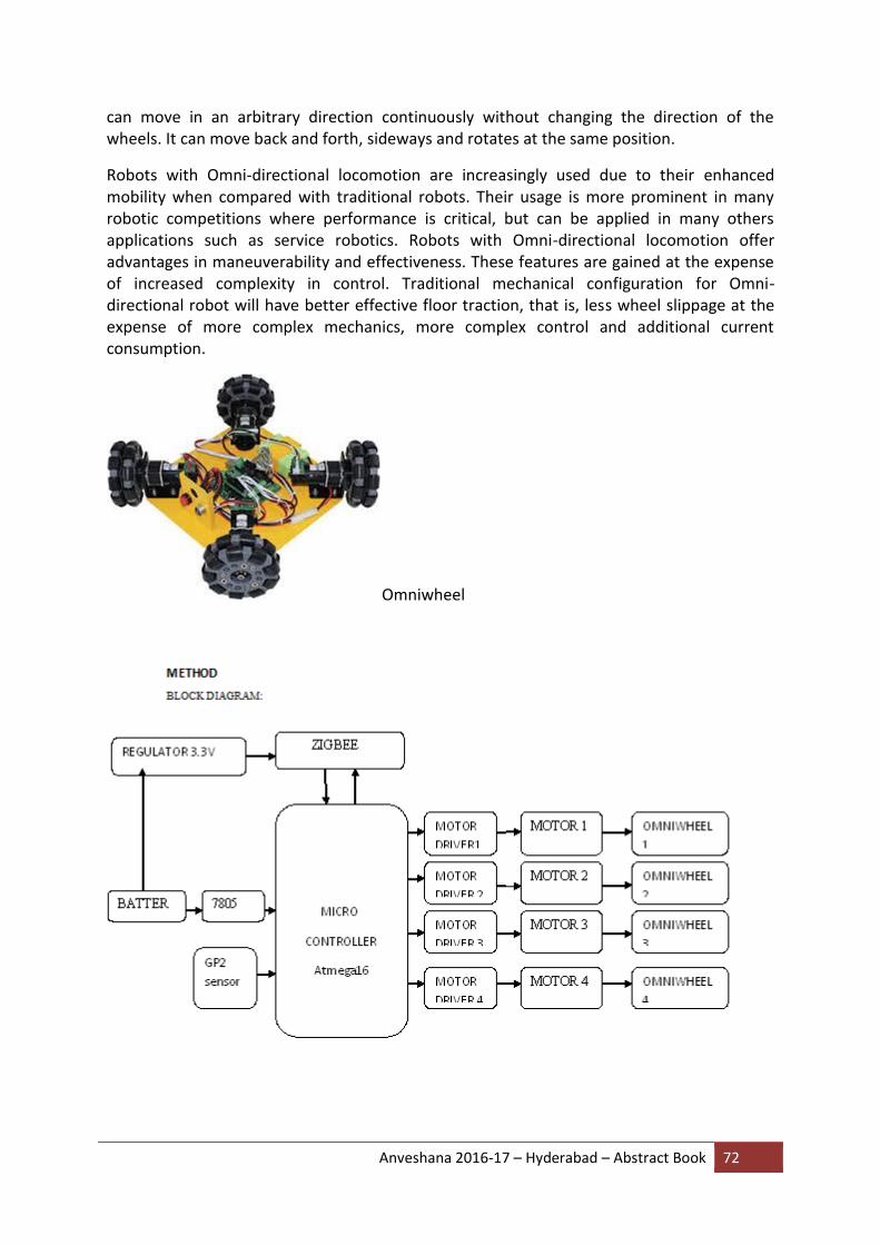
Anveshana 2016-17 – Hyderabad – Abstract Book 72
can move in an arbitrary direction continuously without changing the direction of the wheels. It can move back and forth, sideways and rotates at the same position.
Robots with Omni-directional locomotion are increasingly used due to their enhanced mobility when compared with traditional robots. Their usage is more prominent in many robotic competitions where performance is critical, but can be applied in many others applications such as service robotics. Robots with Omni-directional locomotion offer advantages in maneuverability and effectiveness. These features are gained at the expense of increased complexity in control. Traditional mechanical configuration for Omni-directional robot will have better effective floor traction, that is, less wheel slippage at the expense of more complex mechanics, more complex control and additional current consumption.
Omniwheel
Anveshana 2016-17 – Hyderabad – Abstract Book 73
EXPERIMENT
Hardware Requirements:
i. Atmega 8 & Atmega 16 Microcontrollers
ii. Relay drivers
iii. Omni direction wheels
iv. Motors
v. Zigbee module
vi. Sharp sensor
Software Requirements:
i. Code Vision AVR
WORKING
First the power supply is connected to the robot controller which enables it to operate and control the rest of the components connected to it. The Zigbee module is then connected to the controller board by the TX and RX pins and provides a wireless short range connection between the controller and the computer used to control it. Then the various motor drivers used to control the translational movements .The sensor is then connected to it which enables the robot to avoid obstacles in front of it.
SUMMARY
Remote controlled wireless pick and place robot is intended to control the direction of a Robot through remote control commands. Microcontroller with the user has some push buttons interfaced to it and also it is interfaced with Zigbee module. Whenever the user press any button of that concerned direction, the relevant information to that command is fed to Microcontroller which transmits it through Zigbee module which will be received by the system at Robot. This data is fed to the Microcontroller with robot and is processed by controller and acts accordingly on robot and arm DC motors. DC motors are interfaced through a motor driver which controls the direction of Robot. The main drawback of this system is it uses Zigbee communication mechanism which supports only for limited distance and also it doesn’t give the exact speed of the motor.
COST
This prototype of the quad wheeled Omni directional robot costs around Rs. 4500.
Anveshana 2016-17 – Hyderabad – Abstract Book 74
21. A MONOPOLE MICROSTRIP ANTENNA WITH ENHANCED DUAL
BAND REJECTION FOR UWB APPLICATIONS
COLLEGE: MLR INSTITUTE OF TECHNOLOGY
GUIDE: E. AMARESHWAR
SCHOOL STUDENTS: K. SAI MADHAV, 9th STD, SINDHUJA 9Th STD, ZPHS KUKATPALLY
COLLEGE STUDENTS: MANDALAPU LAVANYA & BELKERI SAI PRAKASH
ABSTRACT
In this paper, a compact, planar ultra-wideband (UWB) monopole micro strip antenna is proposed which offers dual band notch characteristics with enhanced rejection at frequency bands centered at 3.4 GHz and 5.5 GHz. To realize enhanced band notched characteristics at 3.4 GHz, a pair of filters is incorporated which includes an inverted ‘L’ shaped slot and a twisted ‘J’ shaped slot in the patch element. Another pair of filters comprises of a spur line filter in the feed line and ‘U’ shaped slot in the patch are used to get a strong frequency band rejection centered at 5.5 GHz. Step by step development of the antenna with its analysis in frequency and time domain is presented. The prototype is fabricated and the measured results are presented which are in close similarity to the simulated results.
HYPOTHESIS
Here we are going for the rejection because WLAN and WI-MAX are in use, suppose if we want to use other than the frequencies used by these two we need to reject these two bands and also to avoid interference.
METHOD
Here we are going for dual band rejection using four filters like L, U, J, spur line filters which work based on the VSWR ratio.
EXPERIMENT
We are fabricating the dual band rejection micro strip antenna. We are also measuring the frequency rejections at 3.4 GHz and 5.5 GHz and also other antenna parameters (impedance mismatch, VSWR, gain, directivity etc) by using vector network analyzer.
SUMMARY
To minimize the potential interference between the UWB and narrowband systems, such as WiMAX and WLAN, a compact UWB antenna with enhanced dual frequency notch characteristics is proposed and discussed. Out of the four notch ¯lters incorporated in the radiating patch, one pair, i.e., filter-1 and filter-2, provides the band notched characteristics

Anveshana 2016-17 – Hyderabad – Abstract Book 75
at frequency band centered at 3.4 GHz.The other pair of filters, i.e., filter-3 and filter-4, provides the bandnotched characteristics at frequency 5.5 GHz. The notched bands can be controlled by adjusting the dimension and position of the slots. The frequency domain and time domain characteristics of the proposed UWB antenna have been discussed. The antenna is fabricated, and the measured results show good agreement with the simulated ones. Although the proposed antenna employs four filters like L,U,J,spurline filters which makes its design complex, but that is the distinctive feature. A combination of three different methods is used: (i) perturbing the surface current density of the patch, (ii) adding spur line filter in the feed line, and (iii) defected ground plane structure. A reasonably good UWB frequency and time domain characteristics are obtained through these methods.
COST - 600-1000 RS/-

Anveshana 2016-17 – Hyderabad – Abstract Book 76
22. SMART MATTRESS - A SMART SOLUTION TO BEDSORES
COLLEGE: MLR INSTITUTE OF TECHNOLOGY
GUIDE: E. AMARESHWAR
SCHOOL STUDENTS: K. SAI MADHAV, 9th STD, SINDHUJA 9Th STD, ZPHS KUKATPALLY
COLLEGE STUDENTS: MANDALAPU LAVANYA & BELKERI SAI PRAKASH
ABSTRACT This project aims at the monitoring and prevention of bedsores at early stages of its formation by using smart bed which incorporates sensors and is programmed so as to notify the caretaker of the concerned patient with immediate effect.
Our aim is to materialize cost effective design of a smart bed for prevention of bed-sores or pressure ulcers ailing the bedridden elderly. The focus of this project is to develop a software/hardware platform that addresses one of the most costly, acute health conditions, pressure ulcers - or bedsores. Caring for pressure ulcers is extremely costly, increases the length of hospital stays and is very labour intensive. The proposed platform collects information from various sensors incorporated into the bed, analyzes the data to create a time-stamped, body pressure distribution map and triggers an alarm sends a message when pressure is applied on a particular area for a long period of time to alert the caretaker.
Pressure ulcers have been described as one of the most costly and physically debilitating complications in the 20th century. Pressure ulcers are the third most expensive disorder after cancer and cardiovascular diseases. Once developed, PU represents an acute health condition that results in increased costs and suffering over many months and even years. Effective ulcer prevention and early detection will greatly reduce patient suffering/discomfort.
HYPOTHESIS
Machine intelligence is used to analyze data, assess the risk and alert care-givers to intervene at an early stage to prevent pressure ulcers.
Providing support for the hospital staff in all of these areas allows the bed to truly amplify their abilities such that they can be more efficient, and successful in caring for patients, especially with regard to pressure ulcers.
It is very cost effective compared to alternative methods used for prevention of pressure ulcers
METHOD
Block diagram:

Anveshana 2016-17 – Hyderabad – Abstract Book 77
The above shown block diagram depicts the path followed by the system in monitoring and prevention of bed sores. The bed in which the patient is supposed to lie down is aligned with pressure sensors. The readings from these sensors are taken at regular intervals of time. These readings are given to the microcontroller which is programmed for the specified function. From here, either an alarm can be triggered or a message can be sent to the concerned person through cloud computing. This can gain the attention of the concerned person who will take the required step. This can be either changing the position of the patient or tend to his needs.
A. Data Collection & Monitoring: In order to measure pressure over the entire body, pressure sensors are distributed over the bed’s surface in an array format. The technology behind large area sensing using a sensor matrix has been advanced in the past decade and currently several pressure sensor arrays are offered in the market but these are very expensive and not easily available in Asian countries.
We propose to make a unit that generates a profile from the initial, fused sensor data in order to capture the most important metric that is pressure. The goal is to generate required data set for classification. To build the training set, a complete set of pressure sensors are arranged in an array format.
The sensors used in this case are flex sensors. These sensors are pressure dependent. Here,
when the pressure is seen on the flex sensors, the resistances of these sensors vary
proportionally hence the variance in resistance and indirectly the voltage is observed. This
voltage change is then processed for required output.
B. Data acquiring and assembly:
The data so acquired from the sensors called as the flex sensors are passed on to 4:1 dual multiplexers. These multiplexers are so arranged in order to get the data in analog form and a proper required sequential order. These multiplexers are arranged in such a manner that all rows and columns of the flex sensor matrix are connected to these multiplexers. These multiplexers give the values that are taken from regular intervals of time to the microcontroller (commonly used microcontroller being Atmega).
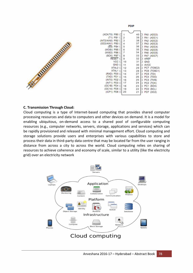
Anveshana 2016-17 – Hyderabad – Abstract Book 78
C. Transmission Through Cloud: Cloud computing is a type of Internet-based computing that provides shared computer processing resources and data to computers and other devices on demand. It is a model for enabling ubiquitous, on-demand access to a shared pool of configurable computing resources (e.g., computer networks, servers, storage, applications and services) which can be rapidly provisioned and released with minimal management effort. Cloud computing and storage solutions provide users and enterprises with various capabilities to store and process their data in third-party data centre that may be located far from the user ranging in distance from across a city to across the world. Cloud computing relies on sharing of resources to achieve coherence and economy of scale, similar to a utility (like the electricity grid) over an electricity network
Anveshana 2016-17 – Hyderabad – Abstract Book 79
The data so obtained by the pressure map array is then sent for computer processing through a microcontroller device. The device is then programmed according to the specifications of timer and detected pressure and accordingly the output is sent to the net specifically cloud computing. If the pressure of the array is detected and the same persists for the given amount of time then the microcontroller triggers an alarm. The same information is sent to the concerned authority by a message.
By this, the concerned person who may be the doctor, nurse, or any acquaintance will be immediately notified of the patient and that caretaker can chalk out the course of action required for the patient, relieving him/her from the pain and stress of such painful sores at early stage itself.
EXPERIMENT
Worked with the flex sensors and converted the resistance of the flex sensors into voltage. The degree of change in the voltage with respect to change in resistance is recorded. The arrangement of flex sensors is researched and evaluated.
SUMMARY
Pressure ulcers have been described as one of the most costly and physically debilitating complications in the 20th century. Pressure ulcers are the third most expensive disorder after cancer and cardiovascular diseases. The management of these ulcers is ever evolving but the age old saying of “prevention is better than cure “suits this condition the most.
COST – Rs.16,000/-

Anveshana 2016-17 – Hyderabad – Abstract Book 80
23. PHASE-CHANGE MATERIALS
COLLEGE: PRINCETON COLLEGE OF ENGINEERING AND TECHNOLOGY
GUIDE: B.VENKAT NARSIMHA RAO
SCHOOL STUDENTS: NEEKIL 9TH STD,MARUTHI 8TH STD, ZPHS GHATKESAR
COLLEGE STUDENTS: STYAM KUMAR CHOUBEY,MADHUKAR
ABSTRACT
Phase-Change Materials (PCMs) are substances with a high heat of fusion that melt and solidify at a certain temperature range. They are capable of storing and releasing large amounts of energy and have a high capacity of storing heat. PCMs prevent energy loss during material changes from solid to liquid or liquid to solid. They have several advantages such as its self-nucleating properties, and disadvantages such as having low thermal conductivity. There are different types of PCM with a wide range of applications. This paper studies the potential application of PCMs in building as energy conservation materials. The analysis and result shows that the use of BioPCM material as insulation layer in building can decrease the cooling load by 20% in comparison to standard one.
HYPOTHESIS
The potential use of PCMs in construction material, heat transfer and other applications are promising given its magnificent thermo physical properties. PCMs should be incorporated further in global energy management solutions due to the stress for innovations with a low impact on the environment. The results gained from analysis shows a 20% reduction of cooling load when utilizing PCMs materials in comparison to standard construction materials. Accordingly, PCM wall is a promising solution for the problem of depleting fuel resources in the form of latent heat storage materials. PCM should be used in buildings, ceiling tiles, air conditioners, thermal heating and many other applications. Further research is recommended in PCMs application in the construction industry due to its magician properties and potential wide applications.
METHOD More than 500 natural and synthetic PCMs are known in addition to water. They differ from each other by their altering phase change temperature ranges and their heat storage capacities. Other properties of PCM for a high efficient cooling system with thermal energy system (TES) include.
A melting temperature in the desired operating range, in construction this would be 23°C or 26°C.
A high latent heat of fusion per unit volume. In other words, they can store a large amount of heat per unit of volume, minimizing the area of PCM tiles that are needed.
High thermal conductivity. The quicker the PCM reacts to changes in temperature, the more effective the phase changes will be.

Anveshana 2016-17 – Hyderabad – Abstract Book 81
Minimal changes in volume. Substances expand or contract when they change state. Because PCMs in construction need to be contained within a cassette, large changes in volume could create problems.
Congruent melting. This means that the composition of the liquid is the same as that of the solid, which is important to prevent separation and super cooling.
A completely reversible freezing/melting cycle.
Durability over a large number of cycles.
Non-corrosiveness to construction materials.
Non-flammable.
PCMS can be for heating and cooling in buildings, PCM can be placed in porous construction material such as plasterboard to increase heat. As for cooling, air conditioners with PCM collect and store ambient air during the night. PCMs can also be placed in thermoelectric refrigeration to improve effectiveness of the heat sink such as using a window with a PCM curtain.
A PCM curtain fills up the double sheeted gap between the window and the air vent, and upon freezing the PCMs would prevent the temperature of the air from decreasing and this reduces overheating around the window. By altering the state of aggregation of PCMs in a specific temperature range, applications of PCMs can be placed in apparel, blankets, surgical tools, antibacterial and hygiene applications, insulation, clothing and many more.
EXPERIMENT
The study investigates the inclusion of PCM in concrete; this modified concreted (from now on called PCM-concrete) was then used to build one of the two identically shaped cubicles. The cubicles were designed with the help of TRNSYS using the Type developed by the authors for such application, and validated. The PCM used was a commercial microencapsulated with a melting point of 26ºC, and a phase change enthalpy of 110 kJ/kg. Its mixture and inclusion in the concrete was developed within and the mechanical strength and thermal behavior was tested. It was found out that the PCM-concrete reaches a compressive strength over 25 MPa and a tensile strength at break over 6 MPa (after 28 days). These values open the opportunity for structural purposes. Also other properties tested give rise to the conclusion that a real use of this new concrete. The panels for the mechanical and thermal tests to evaluate walls behavior were performed.
COST - INR 3000/-
Anveshana 2016-17 – Hyderabad – Abstract Book 82
24. ROTATING BUILDING USING WITH SOLAR ENERGY
COLLEGE: PRINCETON COLLEGE OF ENGINEERING AND TECHNOLOGY
GUIDE: P. SANTOSH
SCHOOL STUDENTS: VENKAT GANESH 9TH STD,FARHAN 8TH STD
COLLEGE STUDENTS: B.VIJAYA LAKSHMI, SABA ANJUM
ABSTRACT
In recent years, various rotating buildings such as residential buildings, restaurants and pubs have been designed and constructed. Most of these rotating buildings do not possess passive solar design features or they cannot respond passive solar design principles entirely because the primary design purpose of these rotating buildings is to make all spaces view the landscape as required. Passive solar design is the optimum utilization of architectural peculiarities of a building and appropriate material selection for improving energy efficiency of a building in heating, cooling and natural lighting. While projecting a passive solar building, different factors including building orientation, latitude of the location and climatic properties must be taken into consideration. Passive solar buildings are superior to conventional buildings in terms of various aspects they have some deficiencies as well. Despite insulation, large south facing windows which are designed to maximize solar heat gain in winter turn out to be heat loss areas in cold winter nights. They also cause excessive solar heat gain in summer. So as to eliminate such disadvantages of passive solar buildings, direction of buildings can be changed in winter and in summer by rotating them.
HYPOTHESIS
Rotating buildings offer invaluable benefits for energy efficient design. Rotating buildings could make the best use of solar energy. This concept becomes increasingly
Important since the progressive decrease of the energy resources on earth and the increase in CO2 emissions together with the rise of energy costs are actual problems in today’s world. For that reason the use of alternative energy resources in heating, cooling and lighting buildings has begun to be Solar energy, supplying both heat and light, is mostly applied energy resource to achieve these requirements.
METHOD
1. The rotating building will be constructed in two main phases. The central core will take just six months to be constructed using slip forms that allow the erection of a floor every two days.

Anveshana 2016-17 – Hyderabad – Abstract Book 83
EXPERIMENT
1. The aim of the experiment is could make the best use of alternate energy resource such as heating and cooling and lighting the building by solar resource.
2. The moment of inertia included the stiffness of the element and it depends on the rotation of the element.
3. The top mass is supported in bearings the orientation is not critical since all the mass could act as it ware lumped in the centroid.
4. The orientation of structure will not change the period of whole building in case of earth quake.
SUMMARY
The passive solar design principle is energy efficient. For doing this almost all materials and design of the building are based on their thermal properties and passive solar design principles. The motivation of the thesis is to investigate the effectiveness and efficiency of a rotating solar building. The cost of constructing the rotation system is important. In future studies, cost analysis can be carried out to find out the period of time in which the saved energy pays off the cost of rotation system. Another subject for future studies can be on energy savings of rotating buildings that have the efficiency and cost analysis of their rotating system. In colder climate conditions this case might have performed better than thermal performance of rotating solar buildings in different climate conditions can be studied in future studies.
COST - INR 2000/-

Anveshana 2016-17 – Hyderabad – Abstract Book 84
25. ENERGY EFFICIENT ENGINES (BOOSTER)
COLLEGE: VAAGESWARI COLLEGE OF ENGINEERING
GUIDE: B.RAVINDER
SCHOOL STUDENTS: L.ANIL 8ThSTD, B.SANTHOSH 9Th STD, ZPSS SEETHARAMPALLY
COLLEGE STUDENTS: S.AVINASH, S.SATHISH
ABSTRACT
Booster is designed for Rural and Middle class people for their agricultural and commercial purpose. Booster efficiently works in agricultural fields also as a result of which farmers can transport goods and grass to their animals. It is useful for their regular works, commercial and official works. Booster having two seats at front and space provided at the back for more two seats (or) to transport goods
In the booster used, we have considered unconditioned Bajaj 2007 model auto engine and all spare parts of car taken from scrape and made it conditioned.
The main aim of this booster is taking less amount of fuel and giving more mileage when compared to present day vehicles. The mileage of the booster is 39. Village roads are not much comfortable driving in modern vehicles. To overcome this problem we have designed a booster that can easily move on village roads. The top speed of the vehicle is 100.
The main aim of this booster is giving more mileage by taking less amount of fuel and easy to drive and specially designed chassis made by mild steel material, low maintenance cost and technical repair occurrence is also less when compared to other vehicles.
BLOCK DIAGRAMS
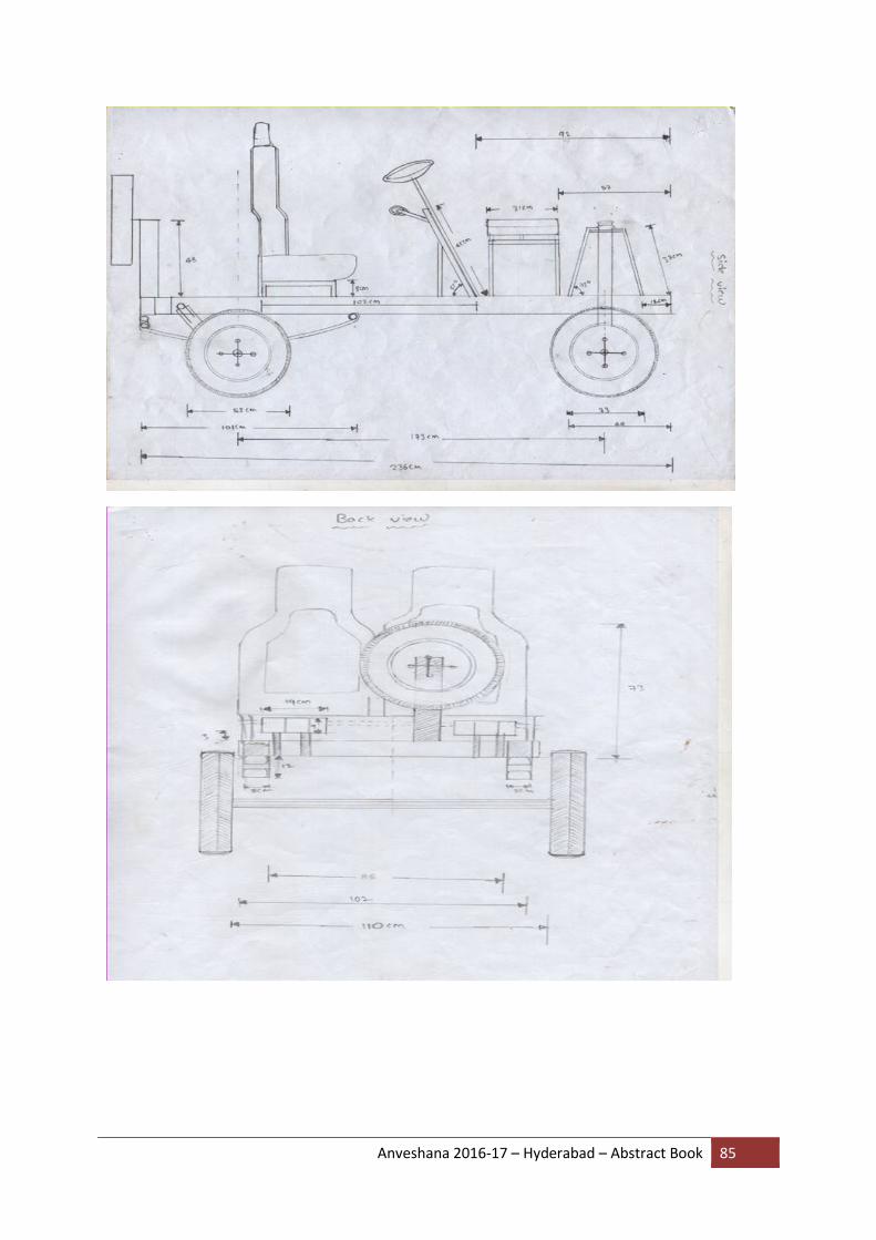
Anveshana 2016-17 – Hyderabad – Abstract Book 85

Anveshana 2016-17 – Hyderabad – Abstract Book 86
TECHNICAL DATA
COST – INR 60000/-

Anveshana 2016-17 – Hyderabad – Abstract Book 87
27. SMARTER LEVEL CROSSING SYSTEM
COLLEGE: N.R.I INSTITUTE OF TECHNOLOGY
GUIDE: M.GAYATHRI
SCHOOL STUDENTS: MD.ANEES 9THSTD, M.SAI SHYAM SUNDHAR 9TH STD, SRI NAVABHARATHA HIGH SCHOOL
COLLEGE STUDENTS: G.SIVA LOKESH KUMAR,G.SHANMKHA SAI KIRAN
ABSTRACT
One of the major safety threats to the railway arises from the presence of unofficial level crossings which very often take the form of distributed crossing along a broad right of way frontage in the exit areas of cities. Due to illiterates and violation of rules these accidents are a major concern to deal with .So in order to eliminate the human perfunctory actions this paper give out the remedy to railway accidents.
INTRODUCTION
Firstly railway accidents occurring due to act of people are overcome by mounting the ultrasonic sensors on the pole near the gate of the level crossing which detects the distance of vehicles or any obstacle. Along the length of the rail road poles are placed upon which ultrasonic sensors are mounted upon them to detect the distance of the obstacle. The signal indication is given to loco pilot as a sign of an obstacle and required steps are taken by the loco pilot to halt the train.
COMPONENTS
1. Atemaga 328p mc
2. Water proof ultrasonic sensor
3. Lights for sign to loco pilot
WORKING AND OPERATION

Anveshana 2016-17 – Hyderabad – Abstract Book 88
ADVANTAGES
1. High efficiency
2. Accurate
3. Low price
4. Easy to operate
CONCLUSION
The main aim of this project is to completely nullify the impact of humans perfunctory actions on railway accidents

Anveshana 2016-17 – Hyderabad – Abstract Book 89
28. 3-AXIES MEMS CONTROLLED WHEEL CHAIR
COLLEGE: SRIDEVI WOMENS ENGINEERING COLLEGE
GUIDE: K. TULASI RAM
SCHOOL STUDENTS: P. MANISHA 9th STD, V.VISHAL 8th STD, ZPHS VATTINAGULAPALLY
COLLEGE STUDENTS: V. TEJASWI, G. HIMA SRI
ABSTRACT
This project introduces an automated system to be developed to control the motor rotation of wheelchair based on head and hand movement of physically challenged person. In order to facilitate these people for their independent movement, an accelerometer device MEMS based sensor transmitter is fitted either on person’s head or hand. Based on the head or hand movements the transmitter will generate command signals which will be received by receiver fitted on the back of the chair. This receiver after receiving signal will drive the motor fitted to the wheel chair MEMS sensors a small, thin, low power, complete 3-axis accelerometer with signal conditioned voltage outputs, all on a single monolithic IC. The wheel chair can be driven in any of the directions i.e. left, forward, back. The automated wheelchair is based on simple electronic control system and the mechanical arrangement that is controlled by an AVR microcontroller. This automatic wheel chair also helps people who have various other disabilities to sit on the chair and just hold the accelerometer and move it over to control the vehicle movements.
HYPOTHESIS
The main objective of this three axis mems controlled wheel chair is to move the disabled person by himself without the help of another person. In day to day life we see the person who is sitting in wheel chair is moved from one place to other place with the help of other person.in this 3axis wheel chair we are using a 3axis accelerometer mems sensor to move the chair. This sensor is fitted either head or hand of the patient .so, by using this sensor he can move himself from one place to another place.
METHOD
Here we are using ADXL335 MEMS sensor. The ADXL335 is a complete 3-axis acceleration measurement system. The ADXL335 has a measurement range of ±3 minimum. The output signals are analog voltages that are proportional to acceleration.
Here we are using ATMEGA8 microcontroller. Which is of 25 pins and all are of bidirectional. Microcontroller is used to program the mems sensor.
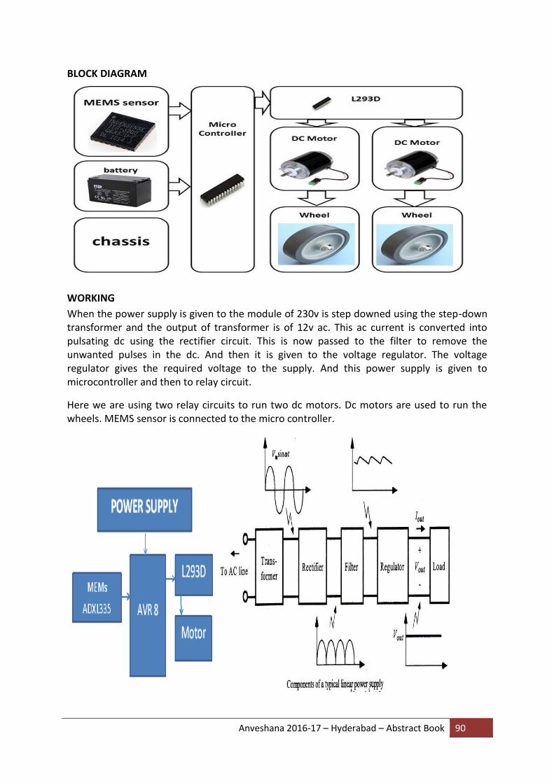
Anveshana 2016-17 – Hyderabad – Abstract Book 90
BLOCK DIAGRAM
WORKING
When the power supply is given to the module of 230v is step downed using the step-down transformer and the output of transformer is of 12v ac. This ac current is converted into pulsating dc using the rectifier circuit. This is now passed to the filter to remove the unwanted pulses in the dc. And then it is given to the voltage regulator. The voltage regulator gives the required voltage to the supply. And this power supply is given to microcontroller and then to relay circuit.
Here we are using two relay circuits to run two dc motors. Dc motors are used to run the wheels. MEMS sensor is connected to the micro controller.

Anveshana 2016-17 – Hyderabad – Abstract Book 91
EXPLANATION Here we are using many components like transformer, rectifier, capacitor, voltage regulator, relays, motors.
Transformer It is used to convert A.C current to D.C current. We are using step down transformer.
Rectifier It is used to convert A.C to pulsating D.C. we are using bridge rectifier.
Capacitor It is used to store the current .in our circuit we are using capacitor as filter.
Voltage regulator A voltage regulator is used to maintain constant voltage in the circuit.
Relay A relay is an electrically operated switch. Low power devices such as microprocessors van drive relays to control electrical loads beyond their direct drive capability.
D.C motors A dc motor is an electrical machine which converts direct power electrical current in to mechanical power.
SUMMARY
This project is mainly designed for the physically challenged people who cannot move without the help of other persons.by using this chair one can move himself from one place to another.
The design of the chair if modified can accommodate a mechanism for climbing the stairs.
COST - INR 7500/-

Anveshana 2016-17 – Hyderabad – Abstract Book 92
29. BOMB DETECTING AND DEFUSING ROBOT
COLLEGE: SREE DATTHA GROUP OF INSTITUTIONS
GUIDE: B.BHARATHI
SCHOOL STUDENTS: B.JAY VARSHITH, A.ADITYA RAM (SLATE THE SCHOOL)
COLLEGE STUDENTS: V.VIJETHA, G. AJAY KUMAR, N.USHA SRE, G.PRASANNA
ABSTRACT
In recent years, the definition of a robot is generally used to mean an unmanned system or automation, as often seen in industrial applications, deep sea planetary probes. Historically speaking, a robot used to be shaped like humans, and referred to as machines and electric systems that were capable of performing similar actions as humans. It is these robots that play active roles in comic magazines, animation and science fiction. Because they are artificially created, they are called artificial man. And since they look like humans in appearance, they are often called androids or humanoids.
BLOCK DIAGRAM
A cyber created by combining organisms and machines, can be called a robot in a broad sense. Automata and other similarities could be considered a robot in its earliest stage. It might be just a box of tools or a suitcase someone lost, either way suspicious unattended packages are reason enough to clear Airports, Shopping malls or the whole neighborhood. But while most humans are evacuated from the potential blast zone, it is only the bomb squad who risk their lives to detect and defuse the bomb. This paper comes with a solution to detect and defuse the bomb without putting the human life in risk and it is the Bomb Detecting and defusing robot.

Anveshana 2016-17 – Hyderabad – Abstract Book 93
HYPOTHESIS
WHAT IS ROBOTICS?
Robotics is a branch of applied science, the popular conception of which came not from science, but from drama, fiction and cinema. The word ―robot‖ was first used in 1921 by Czech playwright Karel Capek in his play Rossum‘s Universal Robots‖ where robots were machines resembling human beings except that they were exceptionally hardworking. The word ―Robotics‖ which means the study of robots, was later coined in 1942 by science fiction writer Isaac Asimov in his story ―Runaround‖ where he put forward three ―laws‖ of robotics. Science fiction writers including Asimov and filmmakers used the concept of robots widely and projected robots as human-like mechanical ―beings‖ with tremendous physical and intellectual capabilities, compared to which even the most sophisticated robots of today will look very primitive.
This budding of the new science in the cradles of arts had two-fold results. On one side, robotics got a natural terminology straight from human anatomy with words like arm, shoulder, elbow, wrist, hand, finger, leg, knee, ankle, foot etc and an ideal system, namely the human body, to get new ideas and to evaluate the performance of existing system. On the other hand, a myth was created in the minds of lay- men regarding human-like machines called robots, the sophistication of which is quite phenomenal.
To many people, the word ―robot‖ gives rise to a mental picture of a metallic human of tremendous strength and a picture of an actual robot would be rather disappointing. An actual industrial robot can, of course, look similar to a human arm, in basic mechanical architecture. For example, the motion capabilities of a six degrees of freedom PUMA robot can be explained in analogy with movements at shoulder, elbow and wrist of a human arm. Many other robots, however, depart from this analogy to different extents depending on their architecture, though they perform the same jobs as PUMA. The four principal components of a robot, namely the manipulator, the controller, the sensors and the actuators roughly resemble in function (though not in appearance) the human arm, brain, sense organs and muscles.
METHOD
ROBOT INTELLIGENCE AND VISION
Intelligence, as pertaining to human beings, is a very subtle and profound quality which cannot be learnt or taught (though can be enhanced in scope and application) and cannot be described in terms of logic and knowledge alone. Again, knowledge is much more than a collection of pieces of information. As the so-called machine intelligence of the present time basically stems from the information and logic coded in computer, we cannot expect true ‗intelligence‘in a robot right now in the sense of the robot having true ‗understanding‘. Still, the intelligent robots, as they are called, constitute an extremely popular topic in robotics, because they can perform various tasks in an apparently intelligent manner.
For example, machine intelligence can be applied for path planning and obstacle avoidance by maintaining (and updating) a complete CAD model of the working environment such that the robot navigates through obstacles without collision. As sight, sound and touch assist human intelligence so far as the knowledge of the external world is concerned, robots also

Anveshana 2016-17 – Hyderabad – Abstract Book 94
are equipped with sensors (optical, ultrasonic, tactile) for feedback. When a robot has to work in a poorly structured or un- structured environment (the environment not being completely known a priori), the robot intelligence heavily relies on ‗vision‘, which is the process of extracting, characterizing and interpreting information from two-dimensional images of the three-dimensional world. In the whole 15 processing of an image, the interpretation of a scene is the most difficult task and requires highest level of intelligence. The maturity of this technique is expected to provide tremendous decision-making capabilities to the robots. The dream of perfection for the science of robotics is a system equipped with high-performance sensors and stereo vision, such that it can work in unstructured environment where changes in scenario may be rapid and unexpected. In addition, certain degree of fault-tolerance is desirable with decision-making capabilities such that it can perform tasks assigned to it as long as they are physically possible.
BLUETOOTH
Bluetooth is a wireless technology used to transfer data between different electronic devices. The distance of data transmission is small in comparison to other modes of wireless communication. This technology eradicates the use of cords, cables, adapters and permits the electronic devices to communicate wirelessly among each other. Bluetooth is a standard used in links of radio of short scope, destined to replace wired connections between electronic devices like cellular telephones, Personal Digital Assistants (PDA), computers, and many other devices. Bluetooth technology can be used at home, in the office, in the car, etc. This technology allows to the users instantaneous connections of voice and information between several devices in real time. The way of transmission used assures protection against interferences and safety in the sending of information. Between the principal characteristics, must be named the hardiness, low complexity, low consume and low cost.
EXPERIMENT
We can transmit command to the robot to make it move in any direction to achieve our task. Moreover this can be achieved using simple wireless communication. The transmitter part consists of the keypad interfaced to the microcontroller. Any button number in decimal format is converted to 4 digit binary by the microcontroller and the parallel output at one of its port is applied to the encoder. The encoder converts this parallel data to serial data and this is fed to the transmitter, fitted with an antenna to transmit the serial data. The receiver side consists of a decoder interfaced to the microcontroller. The decoder converts the received command in serial format to the parallel form and gives this data to the microcontroller. Based on this command the microcontroller sends the appropriate input signals to the motor drivers to drive the respective motors. The system consists of two motors for providing motion to the whole robot and two other motors to provide the arm motion. The end effector or the gripper needs to be controlled to apply proper pressure on the object to handle it effectively, to give it a soft grip. This is ensured by controlling the arm motors through proper command. The output from the arm motors is connected to a 10Ohms/2W resistor and at the time of motor over load or locked condition, a high voltage is developed across the resistor, which causes a logic high level at the output of the optoisolator and the interrupt pin of the microcontroller connected to the optoisolator output through a pnp transistor gets logic low signal, which halts all other operations of the gripper. Thus through simple RF communication, we can actually control a pick and place robot. we connect robot via bluetooth device and that connect phone to operate. Metal detector circuit, detect metal and robot is pick the metal take away from site and drop it

Anveshana 2016-17 – Hyderabad – Abstract Book 95
ADVANTAGES
It can be altered to suit the needs of the user
It is fast and robust
It can handle different loads
It can be controlled remotely
It has a 3-degree of freedom robotic arm
APPLICATIONS
Detection of metal or bomb in disposal areas
It can be operated over 100m range
The robotic arm can be used to transport the suspected things
SUMMARY
The Wireless Bomb Disposal Robot has been designed in such a way that it can cater to the
needs of the bomb disposal squad, the military, the police and also for the personnel who
handle radioactive materials. It has countless applications and can be used in different
environments and scenarios. For instance, at one place it can be used by the bomb disposal
squad, while at another instance it can be used for handling mines. Other application can be
used to provide up to date information in a hostage situation.
COST - INR 2000/-
Anveshana 2016-17 – Hyderabad – Abstract Book 96
30. TEEKA
COLLEGE: G.NARAYANAMMA INSTITUTE OF TECHNOLOGY AND SCIENCE
GUIDE: I.RAVI PRAKASH REDDY
SCHOOL STUDENTS: T.DURGESHWARI, 9TH STD, S.SRIRSHA, 9TH STD, ZHPS,MANIKONDA
COLLEGE STUDENTS: K.SIVANI, V.AISHWARYA
ABSTRACT
During the past 50 years, immunization has saved more than a billion lives and prevented countless illnesses and disabilities. Most children in India are not immunized due to the ever changing vaccine schedules and lack of awareness .Compounding this problem is the fact that immunization records are often scattered and are not appropriately recorded. Many adolescents and adults are unaware that they need to supplement their childhood vaccinations. To tackle this problem, we have designed a website, Teeka. Through this website the registered user will be able to get the list of vaccines along with the date to be vaccinated. The user will be notified formerly a day in advance before the due date through an email. The user can also have the record of all the vaccines taken till date which can be further used as an immunization report. The website also provides the user with health tips.
HYPOTHESIS
Over 2 Million children under the age of 5 die every year in India and another 1 Million or more are disabled for life. Vaccination reminder services in several countries have been effective in increasing compliance by 20%. There are over 40 published scientific studies that prove the effectiveness of vaccination reminders. India has 462,124,989 internet users. A well promoted, email reminder service will be the most cost effective method of reminding parents that a vaccination is due.
Through our system, the user will be able to get the list of vaccines along with the date to be vaccinated. The user will be notified formerly a day in advance before the due date through an email. The user can also have the record of all the vaccines taken till date which can be further used as an immunization report. This system also provides the user with the health tips and the side effects of the vaccines.
METHOD
The user can navigate to login, register, and vaccine information and about us pages from home page. Whenever the home page loads, it checks whether it has to send a mail to the user. As soon as the user receives a mail it immediately updates the status as notified. It ignores if the user is already notified.
EXPERIMENT

Anveshana 2016-17 – Hyderabad – Abstract Book 97
In order to receive mail, the user must register first. The registration form consists of username, password, email id, contact number, date of birth, gender, where username and password should be unique. All registered users enjoy privileges like dashboard, vaccination report, reminder notifications and star baby.
The user who is already registered can login using username and password .Once logged in the user can view his report, dashboard, vaccine information and if there are any other details to fill user can make changes in user profile.
Vaccine information consists of vaccine details. It shows whether the vaccine is mandatory or optional according to the age. Each vaccine is provided with important information and what diseases that particular vaccine prevents from. It also gives a rough schedule of the vaccinations to be taken at various ages. The user can read latest articles.
The report is generated according to the DOB of the user which consists of vaccine name, the date at which the vaccine is to be taken and the status whether the user has taken the vaccine or not. To update the status of vaccine the user can select the checkbox if he has taken the vaccine or leave it empty and save the report. If the user wants to add any other vaccine in his report he can click on add button and enter the vaccine name and the date.
In case, if the user want to change any details like email id and contact number he can do so by clicking on change button provided and can also enter extra details such as height, weight and other information of the baby.
To give feedback to the user, rating for a baby is provided. The baby’s rating is given based on the immunization level. For entertainment, user can play a simple matching game to build and improve memory.
SUMMARY
Through Teeka the registered user will be able to get the list of vaccines along with the date to be vaccinated. The user will be notified formerly a day in advance before the due date through an email. The user can also have the record of all the vaccines taken till date which can be further used as an immunization report. The database information is valid and the operations are rightly performed and the database is up to date. Through constant reminders and awareness among the people, the chances of forgetting to get vaccinated decreases and will help in making the world immune.

Anveshana 2016-17 – Hyderabad – Abstract Book 98
31. ORGAN BANKING SYSTEM
COLLEGE: G.NARAYANAMMA INSTITUTE OF TECHNOLOGY AND SCIENCE
GUIDE: I.RAVI PRAKASH REDDY
SCHOOL STUDENTS: K. SIRI , 9TH STD, G. SHRAVANI, 7TH STD ZPHS, MANIKONDA
COLLEGE STUDENTS: A. PRASANNA, G. PRAVALIKA
ABSTRACT
The Online Organ banking System is developed mainly for general hospitals (GH), clinics and other health centers to manage the distribution and optimum utilization of human organs. It is an online system which only can be accessed by public and doctors. The public can retrieve information about available organs in this website. The Public can register with organ Bank and they can post a request if any of the available organs doesn’t match their need. An email confirmation will be send to registered users of organ bank. The request will be processed by the administrator and it will be made known for the public whoever visits the website and when there is an availability of requested organs an email will be send to requested users.
The list of organs which have been taken by doctors will be removed by administrator up to date. The authorized doctors’ account will be maintained by the administrator. The authorized doctors can login and can post a request for retrieval of available organs and can get an organ from this website. The request will be processed by the administrator and requested organ will be made available for transplantation. An email confirmation will be send to organ bank email to notify that the particular organ delivered successfully. This system will help three groups of persons namely doctors and public. Moreover the interfaces for this system have been designed according to the requirement and needs of the current market. This Online Organ Banking System will help to improve the performance of current situation and overcome the problems that arise nowadays.
HYPOTHESIS
Prevailing method of organ banking and checking availability of organs for transplantation is a tedious task. This method has many challenges with regard to fast availability of data, checking availability of organ at the required time and to pass information. Whereas it can be made easier when its replaced with the internet centric process which is easier, faster and efficient.
Existing system of organ banking with direct interaction between hospital and person who is in need of organ is a task which involves various difficulties. Availability of organ is susceptible. This method is more complex. But the complexity and difficulties can be eliminated by adapting the method of online organ banking system.

Anveshana 2016-17 – Hyderabad – Abstract Book 99
METHOD This system has the following modules
Registration Module:
In this module we take all the details of user that is first name, last name, username, password, email id, role of the person like whether he is a normal user, doctor or admin contact number .We take all the values and store them in the table registration details table in database and a mail will be sent to the registered user.
Login Module:
There are three different login modules depending upon the role of the user he enters during registration.
Normal User Login Module:
In this the user enters username and password .Then the username and password is then taken and validated. If he is a registered user, it directs to search page in which the user can search for the organs that are available .And also if they can’t find the organ they require, they have an option to post a request which is another module .If he is not a registered user then it redirects to the registration page with a message that they are not registered users.
Doctor Login Module:
In this the doctor enters username and password .The username and password is then taken and validated .If he is a registered doctor it directs to search page in which the user can search for the organs that are available .And also if they can’t find the organ they require they have an option to post a request which is another module. Here along with the post a request module doctor can have an extra module that is get an organ module .If he is not a registered user then it redirects to the registration page with a message that they are not registered
Admin Module:
In this the admin enters username and password .Then the username and password is then taken and validated. If he is a registered user it directs to Admin entry module in which the admin enters the values of the organs that are present in the organ bank. If he is not a registered user then it redirects to the registration page with a message that they are not registered users.
Post A Request Module:
In this the user enters the username, email id, organ they require and the blood group of the organ that they require .These values get stored in the request table and the requests that are entered will appear on the main page of the website and these requests are sent to mail. If any requested organ gets into our organ bank then a mail will be generated and sent to the respective person who has requested the organ.

Anveshana 2016-17 – Hyderabad – Abstract Book 100
Find an Organ:
In this the user enters the username and password. Then the username and password is then taken and validated. If he is a registered user it directs to search page and can find the available organs. If he is not a registered user then it redirects to the registration page with a message that they are not registered users.
Get an Organ Module:
In this the user enters the username, password .Then the username and password is then taken and validated .If he is a registered user he can find the organs available. The user can select the available organs of his choice. If any of the available organs doesn't match their needs can post a request. If he is not a registered user then it redirects to the registration page with a message that they are not registered users.
Patient Module:
In this the doctor enters the username, password .Then the username and password is then taken and validated .If he is a registered doctor he can find the organs available. The doctor can select the available organs of his choice. If any of the available organs doesn't match their needs can post a request. If he is not a registered user then it redirects to the registration page with a message that they are not registered users. In this the doctor enters the patient details and the values are stored in a table in the database.
EXPERIMENT
The system of organ banking system is a web application which is substitute of present existing organ banking system. It has user login credentials and its Authentication. Users can check data about availability of organs and even avail the right of posting a request using for needed organ internet as a medium. Physicians and can even avail the right of keeping a request for needed organ and get it for transplantation by providing the necessary details. This is a personalized application which is flexible and can be conveniently used by user with a simple interface and it provides information very fast.
SUMMARY
It has been a great pleasure to work on this exciting and challenging project. This project proved good as it provided practical knowledge of not only programming in Java and web based application and no some extent Windows Application and Oracle, but also about all handling procedure related with “Organ Banking System”. It also provides knowledge about the latest technology used in developing web enabled application and client server technology that will be great demand in future. This will provide better opportunities and guidance in future in developing projects independently
COST
Cost is almost zero as it is software.
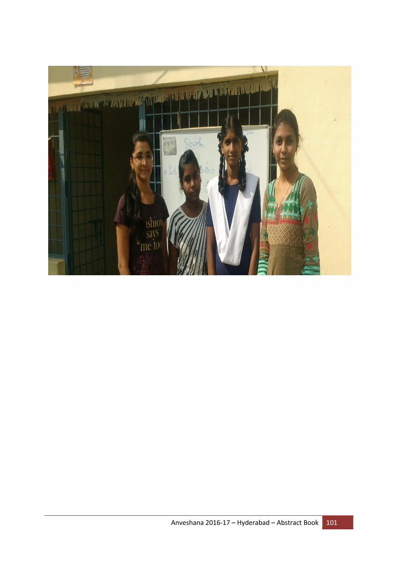
Anveshana 2016-17 – Hyderabad – Abstract Book 101

Anveshana 2016-17 – Hyderabad – Abstract Book 102
32. QUADCOPTER
COLLEGE: VIGNANA BHARATHI INSTITUTE OF TECHNOLOGY
GUIDE: MS. HEMALATHA
SCHOOL STUDENTS: SADU.VISHWANTH, 8TH STD, ANISH SANJAY BADITHE 8TH STD, JOHNSON GRAMMAR SCHOOL
COLLEGE STUDENTS: JAKKULA.SAHARSHA, CHEPURI.SANJAY KUMAR
ABSTRACT
Quadcopters is an aerial vehicle operated to fly independently and is one of the representations of a UAV (Unmanned Aerial Vehicles).They are controlled by pilots on ground or simultaneously driven. They are called rotorcrafts because unlike a fixed wing aircraft, here lift is generated by a set of revolving narrow-chord aerofoils. Drones are actually very fascinating and in this project we are going to study about them, their components and about its widespread applications that determine its scope for the future. They are a mixture of streams of Electronics, Mechanical and especially Aviation. Drones are of different types and have different configurations for example, bicopters, tricopters, quadcopters, hexacopters, octocopters, etc. They have different uses and accordingly respective configurations are used. Hexacopters and Octocopters have better stability and yaw configuration. Control of motion of vehicle is achieved by altering the rotation rate of one or motor discs, thereby changing its torque load and thrust/lift characteristics.
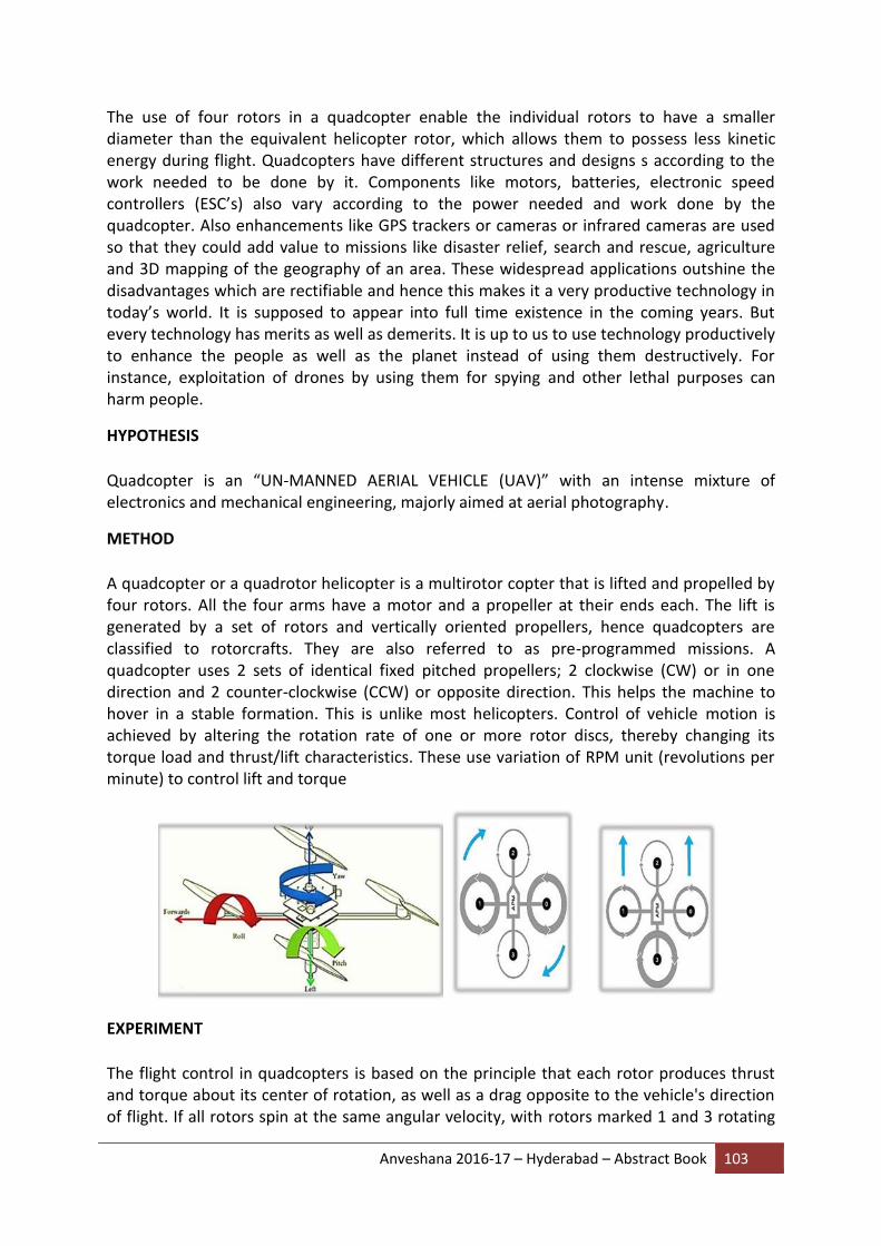
Anveshana 2016-17 – Hyderabad – Abstract Book 103
The use of four rotors in a quadcopter enable the individual rotors to have a smaller diameter than the equivalent helicopter rotor, which allows them to possess less kinetic energy during flight. Quadcopters have different structures and designs s according to the work needed to be done by it. Components like motors, batteries, electronic speed controllers (ESC’s) also vary according to the power needed and work done by the quadcopter. Also enhancements like GPS trackers or cameras or infrared cameras are used so that they could add value to missions like disaster relief, search and rescue, agriculture and 3D mapping of the geography of an area. These widespread applications outshine the disadvantages which are rectifiable and hence this makes it a very productive technology in today’s world. It is supposed to appear into full time existence in the coming years. But every technology has merits as well as demerits. It is up to us to use technology productively to enhance the people as well as the planet instead of using them destructively. For instance, exploitation of drones by using them for spying and other lethal purposes can harm people.
HYPOTHESIS
Quadcopter is an “UN-MANNED AERIAL VEHICLE (UAV)” with an intense mixture of electronics and mechanical engineering, majorly aimed at aerial photography.
METHOD
A quadcopter or a quadrotor helicopter is a multirotor copter that is lifted and propelled by four rotors. All the four arms have a motor and a propeller at their ends each. The lift is generated by a set of rotors and vertically oriented propellers, hence quadcopters are classified to rotorcrafts. They are also referred to as pre-programmed missions. A quadcopter uses 2 sets of identical fixed pitched propellers; 2 clockwise (CW) or in one direction and 2 counter-clockwise (CCW) or opposite direction. This helps the machine to hover in a stable formation. This is unlike most helicopters. Control of vehicle motion is achieved by altering the rotation rate of one or more rotor discs, thereby changing its torque load and thrust/lift characteristics. These use variation of RPM unit (revolutions per minute) to control lift and torque
EXPERIMENT
The flight control in quadcopters is based on the principle that each rotor produces thrust and torque about its center of rotation, as well as a drag opposite to the vehicle's direction of flight. If all rotors spin at the same angular velocity, with rotors marked 1 and 3 rotating
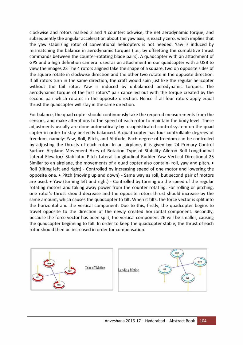
Anveshana 2016-17 – Hyderabad – Abstract Book 104
clockwise and rotors marked 2 and 4 counterclockwise, the net aerodynamic torque, and subsequently the angular acceleration about the yaw axis, is exactly zero, which implies that the yaw stabilizing rotor of conventional helicopters is not needed. Yaw is induced by mismatching the balance in aerodynamic torques (i.e., by offsetting the cumulative thrust commands between the counter-rotating blade pairs). A quadcopter with an attachment of GPS and a high definition camera used as an attachment in our quadcopter with a USB to view the images 23 The 4 rotors aligned take the shape of a square, two on opposite sides of the square rotate in clockwise direction and the other two rotate in the opposite direction. If all rotors turn in the same direction, the craft would spin just like the regular helicopter without the tail rotor. Yaw is induced by unbalanced aerodynamic torques. The aerodynamic torque of the first rotors‟ pair cancelled out with the torque created by the second pair which rotates in the opposite direction. Hence if all four rotors apply equal thrust the quadcopter will stay in the same direction.
For balance, the quad copter should continuously take the required measurements from the sensors, and make alterations to the speed of each rotor to maintain the body level. These adjustments usually are done automatically by a sophisticated control system on the quad copter in order to stay perfectly balanced. A quad copter has four controllable degrees of freedom, namely: Yaw, Roll, Pitch, and Altitude. Each degree of freedom can be controlled by adjusting the thrusts of each rotor. In an airplane, it is given by: 24 Primary Control Surface Airplane Movement Axes of Rotation Type of Stability Aileron Roll Longitudinal Lateral Elevator/ Stabilator Pitch Lateral Longitudinal Rudder Yaw Vertical Directional 25
Similar to an airplane, the movements of a quad copter also contain- roll, yaw and pitch. Roll (tilting left and right) - Controlled by increasing speed of one motor and lowering the
opposite one. Pitch (moving up and down) - Same way as roll, but second pair of motors
are used. Yaw (turning left and right) - Controlled by turning up the speed of the regular rotating motors and taking away power from the counter rotating. For rolling or pitching, one rotor’s thrust should decrease and the opposite rotors thrust should increase by the same amount, which causes the quadcopter to tilt. When it tilts, the force vector is split into the horizontal and the vertical component. Due to this, firstly, the quadcopter begins to travel opposite to the direction of the newly created horizontal component. Secondly, because the force vector has been split, the vertical component 26 will be smaller, causing the quadcopter beginning to fall. In order to keep the quadcopter stable, the thrust of each rotor should then be increased in order for compensation.

Anveshana 2016-17 – Hyderabad – Abstract Book 105
SUMMARY
Quadcopters or drones first came to application as small toys, or school/university projects and then no sooner began to garner widespread attention- used in big-budget movies, photography of high profile sports, agricultural use to rectify lands and detect levels of pesticides as well as other components like nitrogen in plants, search and rescue, land mapping, military etc. The commercial as well as private use of drones is enlarging. The main point is that with growing progress in technology, drones too are coming in different shapes, sizes and configuration (quadcopters, hexa-copters, etc.) for better load and yaw stability. Moreover, extended components like camera, water- resistant components or GPS tracker make it easy in missions of combating, surveillance and especially search and rescue. After 10 years, the market for commercial drones will reach $1.7 billion. Each year, $6.4 billion is being spent developing drone technology. The drones are even providing new job opportunities. 70,000 new drone-related jobs are projected within the next three years in USA alone. 100,000 new jobs are expected till 10 years. Moreover, schools are offering drone degrees & programs in order to provide a trained workforce capable of meeting this demand. This may also prove that there is no need for people to fear about losing their jobs because of replacement by robots or drones.
Anveshana 2016-17 – Hyderabad – Abstract Book 106
33. DIGITAL WATERMARKING
COLLEGE: MARRI LAXMAN REDDY INSTITUTE OF TECHNOLOGY
GUIDE: A.V.PARAMKUSHAM
SCHOOL STUDENTS: PONDU TARAKA LAKSHMI ,9TH STD , NARAN ARCHANA, 8TH CLASS, ZILLA PARISHAD HIGH SCHOOL
COLLEGE STUDENTS: B.UMA SURYA SAI, R.SAMYUKTA
ABSTRACT
Digital watermarking is the act of hiding message related to a digital signal (i.e. an image, song, video ) within the signal itself. Nowadays, digital water marking has many applications such as broadcast monitoring, owner identification, proof if ownership, transaction tracking, content authentication, copy control, device control and file reconstruction. This watermarking technique is used instead of steganography and cryptography. Here in this technique we used a text type of message which is embedded into an image using some kind encoding key to prevent others(strangers) to decode the message if the message was intercepted during transmission. Then the message would be transmitted on a communication channel, which would add some noise to the encoded message. The main specification of watermarking are: Robustness, Imperceptibility, and capacity.
Keywords: watermarking, intercept, eavesdroppers, robustness, imperceptibility.
INTRODUCTION
Embedding a stream of bits in a file is called Digital Watermarking. The file could be an image, audio, video or text. The term "Digital Watermark" was coined by Andrew Tirkel and Charles Osborne in 1992. The first successful embedding and extraction of a steganographic spread spectrum watermark was demonstrated in 1993 by Andrew Tirkel, Charles Osborne and Gerard Rankin.
Watermarks are identification marks made during the paper making process. The first watermarks appeared in Italy during the 13th century, but their use rapidly spread across Europe. They were used to identify the papermaker or the trade guild that manufactured the paper. The marks often were created by a wire sewn onto the paper mold. Watermarks continue to be used today as manufacturer's marks and to prevent forgery.
EXISTING METHODS
Steganography and cryptography are the few of the existing techniques for secure communication in the presence of third parties called adversaries.
Steganography is changing the image in a way that only the sender and the intended recipient is able to detect the message sent through it.
Anveshana 2016-17 – Hyderabad – Abstract Book 107
Cryptography is the science of writing in secret code and is an ancient art .Cryptography is necessary when communicating over any untrusted medium, which includes just about any network, particularly the Internet.
PROPOSED METHODOLOGY To overcome the drawbacks of existing techniques we implement watermarking technique.
Watermarking is used to verify the identity and authenticity of the owner of a digital image. It is a process in which the information which confirms the owner is embedded into the digital image or signal. These signals could be either videos or pictures or audios. For example, famous or popular artists watermark their pictures and images. If somebody tries to copy the image, the watermark is copied along with the image.
Watermarking is of two types; visible watermarking and invisible watermarking.
Visible Watermarking
Visible watermarking refers to the information visible on the image or video or picture. Visible watermarks are typically logos or text. For example, in a TV broadcasting, the logo/symbol of the broadcaster is visible on the screen.
Invisible Watermarking
Invisible watermarking refers to adding information in a video, picture, audio as digital data. It is not visible or perceivable, but it can be detected by different means. It may also be a form or type of steganography and is used for widespread use. It can be retrieved easily.
In this project, we will introduce how to use MATLAB to implement image watermarking algorithms. These algorithms include the most popular ones which are widely used in current literature or more complicated approaches are based upon.
These are commonly divided into three categories (Barni & Bartolini, 2004)
1. Watermarking in Spatial Domain
2. Watermarking in Spectral Domain
3. Watermarking in Hybrid Domain
The supported formats by MATLAB are: bmp, cur, fts(fits), gif, hdf, ico, j2c(j2k), jp2, jpf(jpx), jpg(jpeg), pbm, pcx, pgm, png, pnm, ppm, ras, tif(tiff), and xwd.
Here in text watermarking we use spatial domain algorithm. The text to be watermarked is converted into into their respective ASCII codes and then to binary and inserted in the image.
Watermarking in spatial domain The message can be coded or straight way of arranging bits. The command “bitget” can be used here to create the bit-plane splitter function as depicted below:
function [B8,B7,B6,B5,B4,B3,B2,B1] = bitplane (img)

Anveshana 2016-17 – Hyderabad – Abstract Book 108
B1 = bitget(img,1)*2^0; B2 = bitget(img,2)*2^1 ; B3 = bitget(img,3)*2^2 ; B4 = bitget(img,4)*2^3 ; B5 = bitget(img,5)*2^4 ; B6 = bitget(img,6)*2^5 ; B7 = bitget(img,7)*2^6 ; B8 = bitget(img,8)*2^7 ; End
The first bit-plane is the least significant one (LSB) and most of the time is hardly related to the main shapes of the picture.
RESULTS
When the image is subjected to text water marking the binary values of the message are inserted at some position of the image based on the code. Due to this insertion the value of pixel may be increased, so slight change is observed.
The below shown image is before watermarking and its pixel
The corresponding pixel values of original image i.e.; for only for some part of image
When the original image is watermarked with a text then the following results are observed.

Anveshana 2016-17 – Hyderabad – Abstract Book 109
And corresponding pixel values are:
Therefore by implementing text watermarking any text message can be embedded into an image and some properties can be inculcated like
Robustness: The watermark should be able to withstand after normal signal processing operations such as image cropping, compression, increasing contrast etc.
Imperceptibility: The watermarked image should look like same as the original image to the normal eye. The viewer cannot detect that watermark is embedded in it.
Security: An unauthorized person or a stranger cannot detect, retrieve or modify the embedded watermark.
CONCLUSION The implementation of basic digital watermarking methods in MATLAB is described. Fundamental methods in spatial, hybrid and spectral codes are given. Finally, some solutions for qualifying the watermarking method are described.
FUTURE SCOPE AND APPLICATIONS This thesis work can be extended in two main areas. First, each proposed technique can be improved to better address the applications they are intended for. Furthermore, the digital

Anveshana 2016-17 – Hyderabad – Abstract Book 110
watermarking techniques can be developed to provide better protection for the intellectual property.
Digital watermarking may be used for a wide range of applications, such as:
Copyright protection
Broadcast monitoring (television news often contains watermarked video from international agencies)
Video authentication

Anveshana 2016-17 – Hyderabad – Abstract Book 111
34. PROVIDING SECURITY TO THE VEHICLE AND HUMANS USING
GPS TRACKING SYSTEM
COLLEGE: VNR VIGNANA JYOTHI INSTITUTE OF ENGINEERING AND TECHNOLOGY
GUIDE: N. SANDEEP CHAITANYA
SCHOOL STUDENTS: TARUN CHARY 9TH STD, DILEEP 9TH STD ZPHS BOCHUPALLY
COLLEGE STUDENTS: BODDU PRASHANTH KUMAR, BANDARU SHRAVYA
ABSTRACT
We want to build a software and android application for vehicle tracking(cars) inbuilt system and we want to load the software into a chip and that particular chip will be installed in the vehicle(cars), without that chip the vehicle will not start and stop there itself. The vehicle can be tracked with the help of vehicle number and chassis number (given by Manufacture Company) but the authenticated person can only track the vehicle. At the time of buying the vehicle the owner of the vehicle can update this information into the system. We provide login id and password to every system by using this details he can update this information and any 5-person mobile number can be kept in this system. This system is used to provide security to the vehicle and persons travelling in the vehicle. By building this system we can avoid theft of vehicle s and crimes using the vehicle. If the vehicle undergoes an accident, then it will send message to nearest police station and to the numbers predefined in the system.
HYPOTHESIS
Providing security for the vehicles and Humans by tracking the vehicle and detecting accidents. If any accidents occur, it sends message to the registered numbers.
This problem is so important to tackle because of the following reasons:
o rescues human life in accidents o avoids vehicle theft o to assist the traffic on roads
METHOD
Firstly, we feed the program in the micro controller by loading the Arduino program in the Arduino board.
The program feed can receive the latitude and longitude positions, can detect both fire and vibration accidents.
If any type of accident is detected it can send message to the pre-defined numbers.
we can also track the vehicle and can know the exact location also.
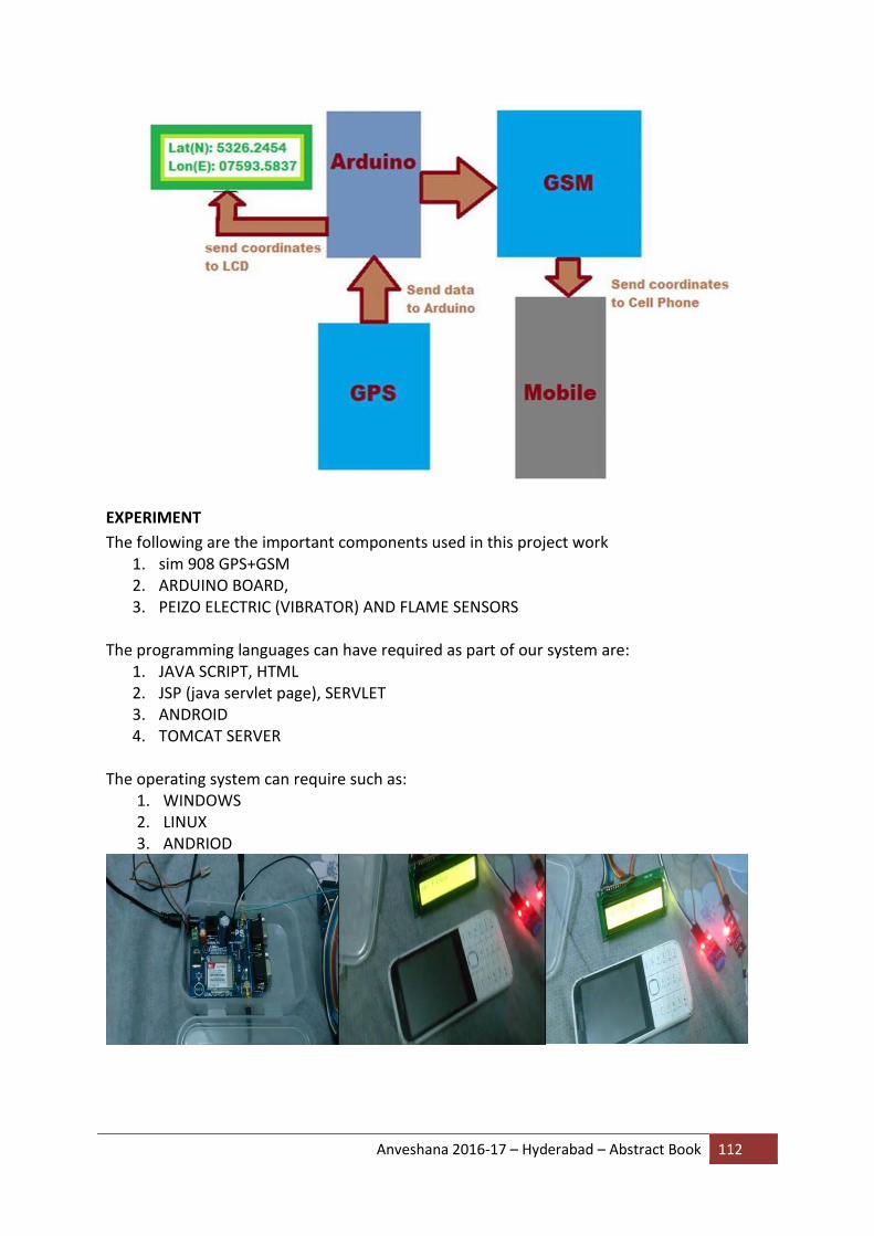
Anveshana 2016-17 – Hyderabad – Abstract Book 112
EXPERIMENT
The following are the important components used in this project work 1. sim 908 GPS+GSM 2. ARDUINO BOARD, 3. PEIZO ELECTRIC (VIBRATOR) AND FLAME SENSORS
The programming languages can have required as part of our system are:
1. JAVA SCRIPT, HTML 2. JSP (java servlet page), SERVLET 3. ANDROID 4. TOMCAT SERVER
The operating system can require such as:
1. WINDOWS 2. LINUX 3. ANDRIOD

Anveshana 2016-17 – Hyderabad – Abstract Book 113
SUMMARY
Main motto of the demonstration is to incorporate different types of sensors so that they
help in decrease the chances of accident.
This device invention is much more useful for the accidents occurred in deserted places and
midnights.
This vehicle tracking and accident alert feature plays much more important role in day to day
life in future.
COST - INR 5500