in sta lla tio n a n d o p e ra tio n · 3.2systemintegration o p s 1 4 5 d 12 395-1 item device...
TRANSCRIPT

i6 0
Ins ta lla tion and opera tion ins tructions
Englis hDate : 06-2012Document number: 81342-1-EN© 2012 Raymarine UK Limited
i60


Trademark and patents noticeAutohelm, hsb2, RayTech Navigator, Sail Pilot, SeaTalk, SeaTalkNG, SeaTalkHS and Sportpilot are registered trademarks of RaymarineUK Limited. RayTalk, Seahawk, Smartpilot, Pathfinder and Raymarine are registered trademarks of Raymarine Holdings Limited.FLIR is a registered trademark of FLIR Systems, Inc. and/or its subsidiaries.All other trademarks, trade names, or company names referenced herein are used for identification only and are the property oftheir respective owners.This product is protected by patents, design patents, patents pending, or design patents pending.
Fair Use StatementYou may print no more than three copies of this manual for your own use. You may not make any further copies or distribute or use themanual in any other way including without limitation exploiting the manual commercially or giving or selling copies to third parties.
Software updatesCheck the website www.raymarine.com for the latest software releases for your product.
Product handbooks
The latest versions of all English and translated handbooks are available to download in PDF format from the website www.raymarine.com.Please check the website to ensure you have the latest handbooks.
Copyright ©2012 Raymarine UK Ltd. All rights reserved.
ENGLISHDocument number: 81342-1Date: 06-2012


ContentsChapter 1 Important information............................. 7Safety notices................................................................. 7Water ingress ................................................................. 7Disclaimer ...................................................................... 7EMC installation guidelines ............................................. 7Suppression ferrites........................................................ 7Connections to other equipment ...................................... 8Declaration of conformity................................................. 8Product disposal ............................................................. 8Warranty registration....................................................... 8IMO and SOLAS............................................................. 8Technical accuracy ......................................................... 8
Chapter 2 Handbook information............................ 92.1 Handbook information ............................................... 10
Chapter 3 Planning the installation ........................113.1 Installation checklist .................................................. 123.2 System integration .................................................... 133.3 Typical systems ........................................................ 143.4 System protocols ...................................................... 163.5 Parts supplied........................................................... 163.6 Tools required ........................................................... 17
Chapter 4 Cables and connections.........................194.1 General cabling guidance .......................................... 204.2 Connections overview ............................................... 20
Chapter 5 Location and mounting ..........................255.1 Selecting a display location........................................ 265.2 Mounting .................................................................. 275.3 Front bezel ............................................................... 275.4 Selecting a transducer location .................................. 28
Chapter 6 Getting started ........................................296.1 Controls.................................................................... 306.2 Power ...................................................................... 306.3 Data master.............................................................. 316.4 Illumination ............................................................... 316.5 Calibration ................................................................ 32
Chapter 7 Using your display..................................357.1 Pages ...................................................................... 367.2 i60 Wind operation .................................................... 367.3 Group illumination ..................................................... 37
Chapter 8 Using alarms ...........................................398.1 Alarms...................................................................... 40
Chapter 9 Maintaining your display........................419.1 Service and maintenance .......................................... 429.2 Condensation ........................................................... 429.3 Routine equipment checks......................................... 439.4 Cleaning................................................................... 439.5 Cleaning the display case .......................................... 44
9.6 Cleaning the display screen ....................................... 44
Chapter 10 Troubleshooting....................................4510.1 Troubleshooting ...................................................... 4610.2 Instrument troubleshooting....................................... 4710.3 Power up troubleshooting ........................................ 4810.4 Miscellaneous troubleshooting ................................. 4910.5 Self-test .................................................................. 50
Chapter 11 Technical support .................................5111.1 Raymarine customer support.................................... 5211.2 Checking the software version.................................. 52
Chapter 12 Technical specification.........................5312.1 Technical specification ............................................. 54
Chapter 13 Spares and accessories.......................5513.1 Wind transducers .................................................... 5613.2 Spares.................................................................... 5613.3 SeaTalkng cables and accessories ............................ 5713.4 Converters.............................................................. 58
Appendix A NMEA 2000 sentences ........................59
5

6 i60

Chapter 1: Important information
Safety noticesWarning: Product installation andoperationThis product must be installed and operated inaccordance with the instructions provided. Failure todo so could result in personal injury, damage to yourvessel and/or poor product performance.
Warning: Potential ignition sourceThis product is NOT approved for use inhazardous/flammable atmospheres. Do NOT install ina hazardous/flammable atmosphere (such as in anengine room or near fuel tanks).
Warning: High voltageThis product contains high voltage. Adjustmentsrequire specialized service procedures and tools onlyavailable to qualified service technicians. There are nouser serviceable parts or adjustments. The operatorshould never remove the cover or attempt to servicethe product.
Warning: Positive ground systemsDo not connect this unit to a system which has positivegrounding.
Warning: Switch off power supplyEnsure the vessel’s power supply is switched OFFbefore starting to install this product. Do NOT connector disconnect equipment with the power switched on,unless instructed in this document.
Caution: Transducer cableDo NOT cut, shorten, splice the transducer cable orremove the connector. If the cable is cut, it cannot berepaired. Cutting the cable will also void the warranty.
Caution: Power supply protectionWhen installing this product ensure the power sourceis adequately protected by means of a suitably-ratedfuse or automatic circuit breaker.
Caution: Service and maintenanceThis product contains no user serviceablecomponents. Please refer all maintenance and repairto authorized Raymarine dealers. Unauthorized repairmay affect your warranty.
Caution: CleaningWhen cleaning this product:
• Do NOT wipe the display screen with a dry cloth, asthis could scratch the screen coating.
• Do NOT use abrasive, or acid or ammonia basedproducts.
• Do NOT use a jet wash.
Caution: CondensationCertain atmospheric conditions may cause a smallamount of condensation to form on the unit's window.This will not damage the unit and will clear after theunit has been switched on for a short period.
Water ingressWater ingress disclaimerAlthough the waterproof rating capacity of this product meets theIPX6 standard, water intrusion and subsequent equipment failuremay occur if the product is subjected to commercial high-pressurewashing. Raymarine will not warrant products subjected tohigh-pressure washing.
DisclaimerRaymarine does not warrant that this product is error-free or that itis compatible with products manufactured by any person or entityother than Raymarine.Raymarine is not responsible for damages or injuries caused byyour use or inability to use the product, by the interaction of theproduct with products manufactured by others, or by errors ininformation utilized by the product supplied by third parties.
EMC installation guidelinesRaymarine equipment and accessories conform to the appropriateElectromagnetic Compatibility (EMC) regulations, to minimizeelectromagnetic interference between equipment and minimize theeffect such interference could have on the performance of yoursystemCorrect installation is required to ensure that EMC performance isnot compromised.For optimum EMC performance we recommend that whereverpossible:
• Raymarine equipment and cables connected to it are:
– At least 1 m (3 ft) from any equipment transmitting or cablescarrying radio signals e.g. VHF radios, cables and antennas.In the case of SSB radios, the distance should be increasedto 7 ft (2 m).
– More than 2 m (7 ft) from the path of a radar beam. A radarbeam can normally be assumed to spread 20 degrees aboveand below the radiating element.
• The product is supplied from a separate battery from that usedfor engine start. This is important to prevent erratic behaviorand data loss which can occur if the engine start does not havea separate battery.
• Raymarine specified cables are used.
• Cables are not cut or extended, unless doing so is detailed inthe installation manual.
Note: Where constraints on the installation prevent any ofthe above recommendations, always ensure the maximumpossible separation between different items of electricalequipment, to provide the best conditions for EMC performancethroughout the installation
Suppression ferritesRaymarine cables may be fitted with suppression ferrites. Theseare important for correct EMC performance. If a ferrite has to beremoved for any purpose (e.g. installation or maintenance), it mustbe replaced in the original position before the product is used.Use only ferrites of the correct type, supplied by Raymarineauthorized dealers.
Important information 7

Connections to other equipmentRequirement for ferrites on non-Raymarine cablesIf your Raymarine equipment is to be connected to other equipmentusing a cable not supplied by Raymarine, a suppression ferriteMUST always be attached to the cable near the Raymarine unit.
Declaration of conformityRaymarine UK Ltd. declares that this product is compliant with theessential requirements of EMC directive 2004/108/EC.The original Declaration of Conformity certificate may be viewed onthe relevant product page at www.raymarine.com.
Product disposalDispose of this product in accordance with the WEEE Directive.
The Waste Electrical and Electronic Equipment (WEEE)Directive requires the recycling of waste electrical and electronicequipment. Whilst the WEEE Directive does not apply to someRaymarine products, we support its policy and ask you to be awareof how to dispose of this product.
Warranty registrationTo register your Raymarine product ownership, please visitwww.raymarine.com and register online.It is important that you register your product to receive full warrantybenefits. Your unit package includes a bar code label indicating theserial number of the unit. You will need this serial number whenregistering your product online. You should retain the label for futurereference.
IMO and SOLASThe equipment described within this document is intended for useon leisure marine boats and workboats not covered by InternationalMaritime Organization (IMO) and Safety of Life at Sea (SOLAS)Carriage Regulations.
Technical accuracyTo the best of our knowledge, the information in this documentwas correct at the time it was produced. However, Raymarinecannot accept liability for any inaccuracies or omissions it maycontain. In addition, our policy of continuous product improvementmay change specifications without notice. As a result, Raymarinecannot accept liability for any differences between the productand this document. Please check the Raymarine website(www.raymarine.com) to ensure you have the most up-to-dateversion(s) of the documentation for your product.
8 i60

Chapter 2: Handbook information
Chapter contents• 2.1 Handbook information on page 10
Handbook information 9

2.1 Handbook informationThis handbook contains important information regarding yourRaymarine instrument display.
i60 HandbooksHandbooks
Description Part number
Mounting and getting started 88010
Installation and operation instructions 81342
Mounting template 87130
i60 instrument rangeRaymarine's i60 instrument range consists of the following variants:
TackTrue/AppDisplay VMG TackTrue/AppDisplay VMG
1 2
D12549-1
Item Description Part number
1 i60 Analogue windinstrument
E70061
2 i60 Analogue closehauled wind instrument
E70062
i60 WindThe i60 Wind instrument provides a 360º wind direction scaleand can be used as a stand alone unit or as part of a SeaTalk orSeaTalkng network.
i60 Close hauled windThe i60 Close hauled wind instrument provides an expandedindication from 20º to +60º about the bow and stern of the vessel.The i60 Close hauled wind must be used as part of a SeaTalk orSeaTalkng network.
10 i60

Chapter 3: Planning the installation
Chapter contents• 3.1 Installation checklist on page 12
• 3.2 System integration on page 13
• 3.3 Typical systems on page 14
• 3.4 System protocols on page 16
• 3.5 Parts supplied on page 16
• 3.6 Tools required on page 17
Planning the installation 11

3.1 Installation checklistInstallation includes the following activities:
Installation Task
1 Plan your system.
2 Obtain all required equipment and tools.
3 Site all equipment.
4 Route all cables.
5 Drill cable and mounting holes.
6 Make all connections into equipment.
7 Secure all equipment in place.
8 Power on and test the system.
12 i60

3.2 System integration
2 3
6
4 51
D12395-1
Item Device type Maximum Quantity Suitable Devices Connections
1 i60 Wind, Close hauled windinstrument.
As determined by theSeaTalkng bus bandwidthand power loading.
• i60 Wind
• i60 Close hauled wind
• SeaTalkng
2 SeaTalk instrument displays. As determined by the SeaTalkbus bandwidth and powerloading.
• i40
• ST40
• ST60+
• SeaTalkng via the optionalSeaTalk1 to SeaTalkngconverter
3 SeaTalkng Instrument displays. As determined by theSeaTalkng bus bandwidthand power loading.
• i50
• i60
• i70
• ST70
• ST70+
• SeaTalkng
4 SeaTalkng pilot controller. As determined by theSeaTalkng bus bandwidthand power loading.
• ST70
• ST70 +
• p70
• p70R
• SeaTalkng
5 SeaTalkng Multifunctiondisplays.
6 • Raymarine multifunctiondisplays.
• SeaTalkng
6 Raymarine Wind transducersand rotavecta.
• 1 x wind vane transducer, or
• 1 x rotavecta windtransducer.
• Short arm wind vanetransducer.
• Long arm wind vanetransducer.
• Short arm masthead windtransducer.
• Long arm masthead windtransducer.
• Rotavecta wind transducer.
Raymarine transducerconnections.
Planning the installation 13
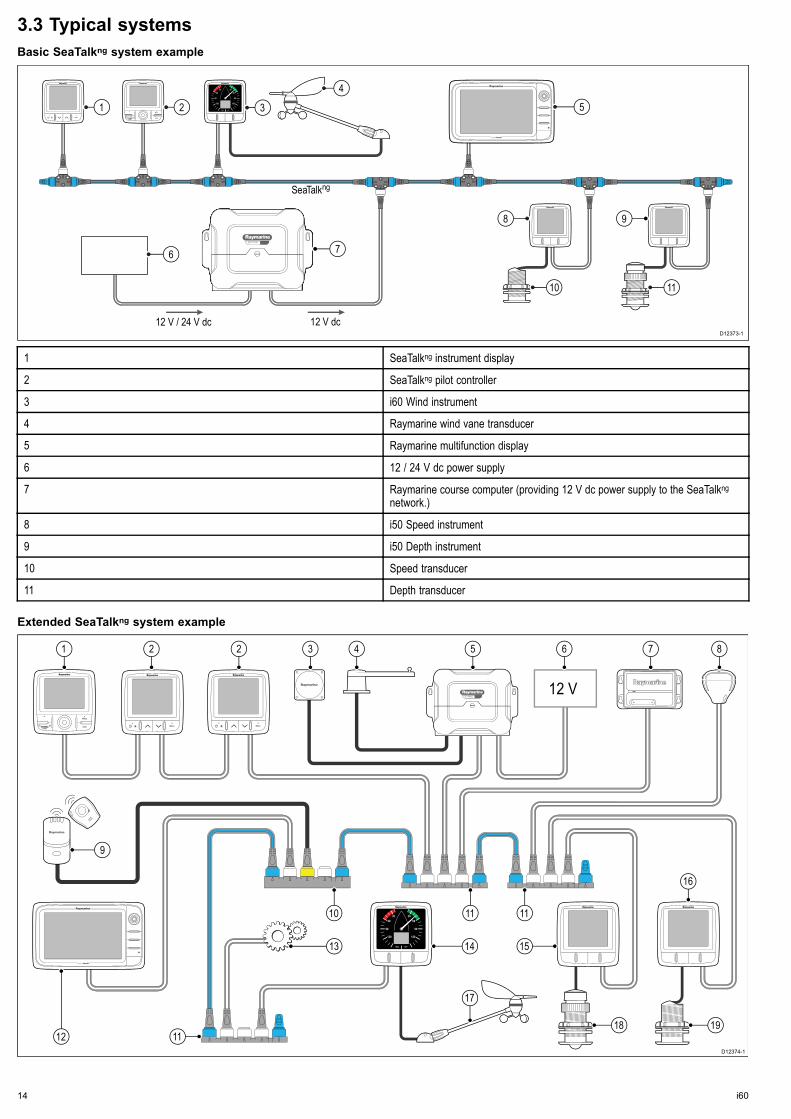
3.3 Typical systemsBasic SeaTalkng system exampleSSMMAARRTTPPIILLOOTT
D12373-1
12 V / 24 V dc 12 V dc
SeaTalkng
1 2
6
10 11
8 9
5
7
3
4
1 SeaTalkng instrument display
2 SeaTalkng pilot controller
3 i60 Wind instrument
4 Raymarine wind vane transducer
5 Raymarine multifunction display
6 12 / 24 V dc power supply
7 Raymarine course computer (providing 12 V dc power supply to the SeaTalkngnetwork.)
8 i50 Speed instrument
9 i50 Depth instrument
10 Speed transducer
11 Depth transducer
Extended SeaTalkng system example SSMMAARRTTPPIILLOOTT 12 V
D12374-1
10
12
11 11
1 2 2 3 4 5
17
6 7 8
16
9
11
151413
18 19
14 i60

1 SeaTalkng pilot controller
2 SeaTalkng instrument displays
3 Fluxgate compass
4 Rudder reference
5 Raymarine course computer (providing 12 V dc power supply to SeaTalkngnetwork.)
6 12 / 24 V dc power supply
7 Raymarine AIS transceiver
8 Raymarine SeaTalkng GPS
9 Man over board
10 SeaTalk to SeaTalkng converter
11 SeaTalkng 5 way blocks
12 Raymarine multifunction display
13 Engine data (via devicenet adaptor cable.)
14 i60 Wind instrument
15 i50 Depth instrument
16 i50 Speed instrument
17 Raymarine wind vane transducer
18 Depth transducer
19 Speed transducer
Planning the installation 15

3.4 System protocolsYour product can be connected to various products and systems toshare information and so improve the functionality of the overallsystem. These connections may be made using a number ofdifferent protocols. Fast and accurate data collection and transfer isachieved by using a combination of the following data protocols:
• SeaTalkng
• NMEA 2000
• SeaTalk
Note: You may find that your system does not use all of theconnection types or instrumentation described in this section.
SeatalkngSeaTalkng (Next Generation) is an enhanced protocol for connectionof compatible marine instruments and equipment. It replaces theolder SeaTalk and SeaTalk2 protocols.SeaTalkng utilizes a single backbone to which compatibleinstruments connect using a spur. Data and power are carried withinthe backbone. Devices that have a low draw can be powered fromthe network, although high current equipment will need to have aseparate power connection.SeaTalkng is a proprietary extension to NMEA 2000 and the provenCAN bus technology. Compatible NMEA 2000 and SeaTalk /SeaTalk2 devices can also be connected using the appropriateinterfaces or adaptor cables as required.
NMEA 2000NMEA 2000 offers significant improvements over NMEA 0183, mostnotably in speed and connectivity. Up to 50 units can simultaneouslytransmit and receive on a single physical bus at any one time,with each node being physically addressable. The standardwas specifically intended to allow for a whole network of marineelectronics from any manufacturer to communicate on a commonbus via standardized message types and formats.
SeaTalkSeaTalk is a protocol which enables compatible instruments toconnect to each other and share data.The SeaTalk cable system is used to connect compatibleinstruments and equipment. The cable carries power and data andenables connection without the need for a central processor.Additional instruments and functions can be added to a SeaTalksystem, simply by plugging them into the network. SeaTalkequipment can also communicate with other non-SeaTalk equipmentvia the NMEA 0183 standard, provided a suitable interface is used.
3.5 Parts supplied
D12388-1
1 2
5 6
98
43
7
1 i60 instrument
2 Front bezel
3 SeaTalk to SeaTalkng adaptor cable
4 SeaTalkng spur cable
5 Gasket
6 Sun cover
7 Documentation pack
8 SeaTalkng blanking plug
9 4 x fixing screws
16 i60

3.6 Tools requiredTools required for installation
D12530-1
3
42
1 5
1 Pozi-drive screwdriver
2 File
3 92 mm (3.62 in) hole cutter
4 Adhesive tape
5 Power drill
Planning the installation 17

18 i60

Chapter 4: Cables and connections
Chapter contents• 4.1 General cabling guidance on page 20
• 4.2 Connections overview on page 20
Cables and connections 19

4.1 General cabling guidance
Cable types and lengthIt is important to use cables of the appropriate type and length
• Unless otherwise stated use only standard cables of the correcttype, supplied by Raymarine.
• Ensure that any non-Raymarine cables are of the correct qualityand gauge. For example, longer power cable runs may requirelarger wire gauges to minimize voltage drop along the run.
Routing cablesCables must be routed correctly, to maximize performance andprolong cable life.
• Do NOT bend cables excessively. Wherever possible, ensure aminimum bend diameter of 200 mm (8 in) / minimum bend radiusof 100 mm (4 in).
100 mm (4 in)
200 mm (8 in)
• Protect all cables from physical damage and exposure to heat.Use trunking or conduit where possible. Do NOT run cablesthrough bilges or doorways, or close to moving or hot objects.
• Secure cables in place using tie-wraps or lacing twine. Coil anyextra cable and tie it out of the way.
• Where a cable passes through an exposed bulkhead or deckhead,use a suitable watertight feed-through.
• Do NOT run cables near to engines or fluorescent lights.
Always route data cables as far away as possible from:
• other equipment and cables,
• high current carrying ac and dc power lines,
• antennae.
Strain reliefEnsure adequate strain relief is provided. Protect connectors fromstrain and ensure they will not pull out under extreme sea conditions.
Cable shieldingEnsure that all data cables are properly shielded that the cableshielding is intact (e.g. hasn’t been scraped off by being squeezedthrough a tight area).
4.2 Connections overviewConnections are made using the provided SeaTalkng and transducercable connectors on the rear of the unit.
SeaTalkng connections
D12056-1
Connecting SeaTalkng cables1. Rotate the locking collar on the back of the unit to the
UNLOCKED position.2. Ensure the spur cable end connector is correctly oriented.3. Fully insert the cable connector.4. Rotate locking collar clockwise (2 clicks) until it snaps into the
LOCKED position.
Transducer connectionsi60 transducer connections
6
7
3
4
5
D12396-1
1
2
1 Blue Rotor + (Rotavecta)
2 Red Rotor – (Rotavecta)
3 Grey Wind 0 V (Shield)
4 Yellow Anemometer (signal)
5 Blue Cosine wind direction
6 Green Sine wind direction
7 Red Wind V+
Note: Connectors 1 and 2 are rotavecta connections, connectors3 to 7 are for wind transducers.
20 i60

Making transducer connections
3 mm
6 mm50 mm1
2
D12359-1
1. Prepare the cable as shown in 1 above.2. Fold back the wire strands and insert into the new spade
connector as shown in 2 above.3. Ensure the wire strands do not extend beyond the rear of the
spade connector insulation.4. Crimp the connector to the wire.
iTC-5 connection
12 V
D12033-3
1 2 3 4
5
6 7 8
1 i50 Depth (Repeater)
2 i70 Instrument (Master)
3 i50 Speed (Repeater)
4 i60 Wind (Repeater)
5 iTC-5
6 Depth transducer
7 Wind vane transducer
8 Speed transducer
Note: Transducers connected to the iTC-5 must be calibratedusing an i70 (master) unit. Transducers connected to the iTC-5cannot be calibrated using an i50 / i60.
Making iTC-5 transducer connectionsFor instructions on connecting transducers to your iTC-5 refer tothe iTC-5 handbook.
Power connectionA SeaTalkng system requires one 12 V dc supply, connected to theSeaTalkng backbone. This can be provided:• By a battery via the distribution panel, or• From a Raymarine course computer, via a SeaTalk or a SeaTalkngsystem.
Power connection example
SeaTalkng power connection
SeaTalkng
D12391-1
12 V3
1 2
1 SeaTalkng instrument.
2 SeaTalkng instrument.
3 12 V dc vessel power supply.
Warning: Grounding not requiredThis product is fully insulated and does NOT requireseparate grounding.
Warning: Positive ground systemsDo not connect this unit to a system which has positivegrounding.
SeaTalk power protectionRaymarine recommends that the power is connected to a SeaTalksystem in such a way that the current drawn on each side of thepower connection point is equal.
SeaTalk power cables
Part number Description
D229 SeaTalk power cable.
SeaTalkng power protectionThe power supply must be protected by a 5 A fuse or a circuitbreaker providing equivalent protection.Raymarine recommends that the power is connected to a SeaTalkngsystem in such a way that the current drawn on each side of thepower connection point is equal.
SeaTalkng power cables
Part number Description
A06049 SeaTalkng power cable
Cables and connections 21

SeaTalkng connection
12 V dc
SeaTalkng
D12531-1
1 1 2 3
4
5 6
7 8
1 i70 instrument displays (SeaTalk)ng)
2 i60 Wind instrument (SeaTalk)ng)
3 Raymarine wind vane transducer
4 12 V dc power supply
5 i50 Speed instrument (SeaTalk)ng)
6 i50 Depth instrument (SeaTalk)ng)
7 Speed transducer
8 Depth transducer
SeaTalkng cabling
SeaTalkng cables and connectors
Connection / Cable Notes
Backbone cables (various lengths) The main cable carrying data. Spursfrom the backbone are used toconnect SeaTalkng devices.
T-piece connectors Used to make junctions in thebackbone to which devices can thenbe connected.
Terminators Required at either end of thebackbone.
Spur cables Used to connect devices. Devicesmay be daisy chained or connecteddirectly to the T-pieces
SeaTalkng 5–way connector Used to branch, split, or makeadditional connections in SeaTalkngnetworks.
SeaTalkng powerThe SeaTalkng bus requires a 12 V power supply. This may beprovided from:
• Raymarine SPX course computer, or
• Other separate regulated 12 V supply.
Note: SeaTalkng does NOT supply power to multifunction displaysand other equipment with a dedicated power supply input.
SeaTalk connectionBasic SeaTalk system example
12 V dc12 / 24 V dc
D12058-2
98
11 12
41 2 3
7
5
6 6 7
10
1 i70 Instrument display (SeaTalkng)
2 i50 Speed instrument (SeaTalkng)
3 i50 Depth instrument (SeaTalkng)
4 Raymarine wind vane transducer
5 i60 Wind instrument (SeaTalkng)
6 SeaTalkng cables
7 SeaTalk to SeaTalkng adaptor cables
8 Speed transducer
9 Depth transducer
10 12 / 24 V dc power supply
11 SeaTalk Course computer (providing12 V dc power to SeaTalk network.)
12 ST6002 pilot controller (SeaTalk)
SeaTalk accessoriesSeaTalk cables and accessories for use with compatible products.
Description Part No Notes
3–way SeaTalk junctionbox
D244
1 m (3.28 ft) SeaTalkextension cable
D284
3 m (9.8 ft) SeaTalkextension cable
D285
5 m (16.4 ft) SeaTalkextension cable
D286
9 m (29.5 ft) SeaTalkextension cable
D287
12 m (39.4 ft) SeaTalkextension cable
E25051
20 m (65.6 ft) SeaTalkextension cable
D288
NMEA2000 connectionYou can either:
22 i60

• Use your SeaTalkng backbone and connect each NMEA2000device on a spur, OR
• connect the instrument display on a spur into an existingNMEA2000 backbone.
Important: You cannot have any 2 terminated backbonesconnected together, unless you have an isolation gatewaybetween the two backbones.
Connecting NMEA2000 equipment to the SeaTalkng backbone
12V NMEA 2000
SeaTalkng
D12380-1
3
1
2
4
1. 12 V dc power supply into backbone.
2. SeaTalkng backbone.
3. SeaTalkng to DeviceNet adaptor cable.
4. NMEA2000 equipment.
Connecting the unit to an existing NMEA2000 (DeviceNet)backbone
D12377-1
1
4
2
3
1. SeaTalkng instrument display
2. SeaTalkng to DeviceNet adaptor cable.
3. DeviceNet backbone.
4. NMEA2000 equipment.
Cables and connections 23

24 i60

Chapter 5: Location and mounting
Chapter contents• 5.1 Selecting a display location on page 26
• 5.2 Mounting on page 27
• 5.3 Front bezel on page 27
• 5.4 Selecting a transducer location on page 28
Location and mounting 25

5.1 Selecting a display locationWarning: Potential ignition sourceThis product is NOT approved for use inhazardous/flammable atmospheres. Do NOT install ina hazardous/flammable atmosphere (such as in anengine room or near fuel tanks).
General location requirementsWhen selecting a location for the unit it is important to consider anumber of factors.
Ventilation requirementsTo provide adequate airflow:
• Ensure that equipment is mounted in a compartment of suitablesize.
• Ensure that ventilation holes are not obstructed.
• Ensure adequate separation of equipment.
Mounting surface requirementsEnsure units are adequately supported on a secure surface. DoNOT mount units or cut holes in places which may damage thestructure of the vessel.
Cable routing requirementsEnsure the unit is mounted in a location which allows proper routingand connection of cables:
• Minimum cable bend radius of 100 mm (3.94 in) is required unlessotherwise stated.
• Use cable supports to prevent stress on connectors.
Water ingressThis unit is suitable for mounting both above and below decks. It iswaterproof to IPX6 standard. Although the unit is waterproof, it isgood practice to locate it in a protected area away from prolongedand direct exposure to rain and salt spray.
Electrical interferenceSelect a location that is far enough away from devices thatmay cause interference, such as motors, generators and radiotransmitters/receivers.
Magnetic compassWhen choosing a suitable location you should aim to maintain themaximum possible distance between the unit and any compasses.To prevent potential interference with the vessel's magneticcompasses, ensure that a minimum distance of 230 mm (9 in)between the unit and any installed compasses is maintained.
Viewing angle considerationsAs display contrast, color and night mode performance are allaffected by the viewing angle, Raymarine recommends youtemporarily power up the display when planning the installation, toenable you to best judge which location gives the optimum viewingangle.
Viewing angle
Dxxxxx-1
70° 70°
70°
70°
Product dimensions
D12389-1
A C G
D E
B F
A 110 mm (4.22”)
B 115 mm (4.52”)
C 14 mm (0.55”)
D 30 mm (1.18”)
E 35 mm (1.38”)
F 90 mm (3.54”)
G 17 mm (0.67”)
26 i60

5.2 Mounting
Pre-mounting checkThe product is designed to be surface mounted. Before mountingthe unit, ensure you have:
• Selected a suitable location.
• Identified the cable connections and route that the cables will take.
• Detached the front bezel.
• Remove the keypad mat.
Mounting diagram
D12379-1
Mounting instructions1. Check the selected location for the unit, a clear, flat area with
suitable clearance behind the panel is required.2. Fix the mounting template supplied with the product, to the
selected location, using masking or self adhesive tape.3. If possible use an appropriate size hole cutting saw and cut
out the centre hole cut out area as indicated on the mountingtemplate, or
4. Using a suitable hole cutting saw, make pilot holes in eachcorner of the cut out area and using a jigsaw cut along the insideedge of the cut out line.
5. Ensure that the unit fits into the removed area and then filearound the cut edge until smooth.
6. Drill any required holes as indicated on the mounting templatefor the securing screws.
7. Connect the relevant cables to the unit.8. Peel the backing off of the supplied gasket and place the
adhesive side of the gasket onto the display unit and press firmlyonto the flange.
9. Slide the unit into place and secure using the screws provided.10.Refit keypad mat and front bezel.
Note: Drill, tap size and tightening torques are dependant uponthe material type and thickness of the mounting surface.
Note: The supplied gasket provides a seal between the unit anda suitably flat and stiff mounting surface or binnacle. The gasketshould be used in all installations. It may also be necessary touse a marine-grade sealant if the mounting surface or binnacle isnot entirely flat and stiff or has a rough surface finish.
5.3 Front bezel
Removing the front bezel
D12372-1
1 2
3 4
Note: Use care when removing the bezel. Do not use any toolsto lever the bezel, doing so may cause damage.
1. Using your fingers pull the bezel away from the unit at the topand side, as shown in 2.The bezel will start to come away from the unit at the top andside.
2. Now pull the bezel away from the unit on the opposite side, asshown in 3.The bezel will now come free from the unit, as shown in 4.
Location and mounting 27

5.4 Selecting a transducer location
Wind vane transducer / rotavecta locationrequirementsThe transducer's location must:
• Allow reasonable access for installation and servicing.
• Be as high as possible and away from any equipment which mayshield the transducer or otherwise disturb the air flow.
• Provide a horizontal mounting surface. If a surface (e.g. masttop) is otherwise suitable but not horizontal, make up a suitablewedged packing piece to provide the necessary horizontalsurface.
• There must also be a viable route for the transducer cable to berouted to the instrument display.
Wind vane transducer and rotavecta mountingEnsure that the wind transducer or rotavecta is installed inaccordance with the instructions supplied with the unit.
28 i60

Chapter 6: Getting started
Chapter contents• 6.1 Controls on page 30
• 6.2 Power on page 30
• 6.3 Data master on page 31
• 6.4 Illumination on page 31
• 6.5 Calibration on page 32
Getting started 29

6.1 Controls
1 32 4D12375-1
1 Display (Power) — Power theinstrument display on and off, adjustbacklight and contrast levels.
2 True / App — Switch between trueand apparent wind direction.
3 VMG— Display Velocity made good.
4 Tack — Tack heading.
6.2 Power
Powering on the unitWith power to the unit turned on but the unit switched off:1. Press and hold the Power button until the unit powers on and
data is displayed (approximately 2 seconds).
Note: When power to the unit is turned on the unit will switchon automatically.
Powering off the unit1. Press and hold the Power button until the power count down
timer is displayed and reaches zero (approximately 6 to 8seconds).
Calibration alertIf the CAL legend on the digital display flashes for the first 30seconds after power up, refer to the Calibration section to calibrateyour unit.
30 i60

6.3 Data masterWhere a system contains more than one unit capable of displayinga data type, the unit physically connected to the transducer must beset as the data master and any other units set as a repeater.
Setting a unit as data master1. Refer to the Intermediate calibration section for details on how to
set your unit as data master.
6.4 Illumination
Adjusting the backlight levelDuring normal operation:1. Press and hold the Power button for approximately 1 second
to display the backlight page.2. Use the VMG or Tack buttons to adjust the backlight to the
required level.
Note: The backlight page will time-out after 8 seconds ofinactivity.
Getting started 31

6.5 CalibrationBefore first use calibration procedures must be carried out to ensureoptimum performance of the instrument with the vessel.The calibration procedures are:
• User calibration
• Intermediate calibration
• Group setup
• Dealer calibration
Note: Group setup is for group illumination and is not part ofthe calibration process.
User calibrationUser calibration options include:
• Wind angle offset
• Wind speed units
Linearizing and aligning the wind transducerYou will need to be underway, with sufficient space to turn in a largecircle unhindered.1. Slowly turn the vessel through 2 complete circles.
x 2
D12415-1
This procedure automatically linearizes the wind vane. Asuccessful linearization is indicated by the digital display flashingand a buzzer sounding three beeps.
2. Press and hold the Power and True / App button simultaneouslyfor approximately 2 seconds to enter the user calibration menu.
TrueApp+
D12488-1
10
15
20253035
40
45
5055 60 5
2
3. Press the Power button to display the wind angle offset page.
D12489-1
4. Sail your vessel directly into the wind and adjust the analogpointer to 0, using the VMG and Tack buttons.
D12490-1
TackVMG
The VMG button will decrease the current value and the Tackbutton will increase the current value. As you do this, the windangle offset shows the amount of correction you have applied.
5. To exit the user calibration pages at any time press and hold thePower and True / App buttons simultaneously for approximately2 seconds.
Selecting wind speed unitsFrom the user calibration pages:1. Press the Power button to display the wind speed units page, or
D12491-1
2. Use the VMG and Tack buttons to select the required wind units.3. To exit the user calibration pages at any time press and hold the
Power and True / App buttons simultaneously for approximately2 seconds.
Intermediate calibrationIntermediate calibration allows you to:
i60 Wind i60 Close hauled wind
Check instrument software version. Check instrument software version.
Check the instrument status (eithermaster or repeater).
10
15
20253035
40
45
5055 60 5
4
+D12492-1
CAL
TrueApp
Checking the software versionDuring normal operation:1. Press and hold the Power and True / App buttons simultaneously
for approximately 4 seconds.The current software version is displayed. The software versionpage will time-out automatically after 8 seconds of inactivity.
2. Press the Power button to display the instrument status.
Checking the instrument statusFrom the software version page:1. Press the Power button.
The instrument status is displayed (r0 = master and r1 =repeater). The instrument status page will time-out automaticallyafter 8 seconds of inactivity.
Dealer calibrationThe dealer calibration procedures include:
• Setting User calibration options on or off.
• Setting required wind angle and speed response.
• Setting the velocity made good (VMG) response.
• Setting boat show mode on or off.
• Restore factory default
Setting dealer calibration optionsDuring normal operation:1. Press and hold the Power and True / App buttons for
approximately 14 seconds to display the dealer cal entry page.
10
15
20253035
40
45
5055 60 5
14
+D12493-1
TrueApp
CAL
2. Press the VMG and Tack buttons simultaneously to display theuser calibration access page.
+D12494-1
TackVMG
CALCAL
3. Use the VMG or Tack buttons to turn user calibration on and off.4. Press the Power button to display the wind angle response page.
D12495-1
CAL
5. Use the VMG or Tack buttons to set the required wind angleresponse values.
6. Press the Power button to display the wind speed responsepage.
D12496-1
CAL
7. Use the VMG or Tack buttons to set the required wind speedresponse values.
32 i60

8. Press the Power button to display the VMG response page.
D12497-1
CAL VMG
9. Use the VMG or Tack buttons to set the required VMG responsevalues.
10.Press the Power button to display the wind speed page.
D12498-1
CAL
KTS
11. Press the VMG or Tack buttons to display the wind speedcalibration page.
D12499-1
CAL
TackVMG +
12.Use the VMG or Tack buttons to adjust the wind speedcalibration value to 0.7.
13.Press the Power button to display the boat show mode page.
D12500-1
CAL
14.Use the VMG or Tack buttons to switch boat show mode onand off.
15.Press the Power button to display the factory reset page.
D12501-1
CAL
16.Use the VMG or Tack buttons to reset unit's settings to factorydefault values.
17.Use the VMG or Tack buttons to adjust the current values oneach page.
18.To exit the dealer calibration pages at any time press andhold the Power and True / App buttons simultaneously forapproximately 2 seconds.
Note: User calibration access, wind speed and boat show modepages are not available on the i60 Close hauled wind.
Getting started 33

34 i60

Chapter 7: Using your display
Chapter contents• 7.1 Pages on page 36
• 7.2 i60 Wind operation on page 36
• 7.3 Group illumination on page 37
Using your display 35

7.1 PagesThe pages available depend on the display variant and are shownin the table below:
i60 Wind i60 Close hauled wind
Wind speed Wind speed
*Beaufort wind speed *Maximum wind speed
*Maximum wind speed VMG
*Maximum true wind speed alarm Tack
*Low true wind speed alarm
*High apparent wind angle alarm
*Low apparent wind angle alarm
VMG
Tack
Note: *These pages are temporary pages and will time-out to theprevious permanent page after 8 seconds of inactivity.
Changing pagesDuring normal operation:1. Press either the Power button to cycle through the pages.2. Press the VMG button to display VMG information.3. Press the Tack button to display tack information.
7.2 i60 Wind operationWhen connected to a relevant rotavecta or wind vane transducerthe i60 provides:
• True and apparent wind direction and speed. Wind speed isdisplayed either in knots, meters per second or as Beaufort scalevalues.
• Velocity made good (VMG) information, when vessel speedinformation is available on the network.
• Tack angle, when heading information is available on the network.
• Maximum wind speed.
• High and low true wind speed alarms.
• High and low apparent wind angle alarms.
Note: Alarms are only available on the i60 Wind instrument,when set as a master unit. No alarms are available on the i60Close hauled wind instrument.
i60 display informationAnalogue displayThe analogue display pointer shows either true or apparent winddirection (Depending on setting).
Digital displayThe digital display LCD shows the following wind information.
• Beaufort wind speed
• True / apparent wind speed
• Velocity made good (VMG)
• Tack heading
• Maximum wind speed
• Wind alarm data
Using the display (Power) button
HI
LO
disp
KTS
KTSKTS
LO KTS
KTS
Display
Display
DisplayDisplay
Display
Display
Display
Tack
10
15
20253035
40
45
5055 60 5
3
D12552-1
During normal operation:1. Use the Display button to cycle through the available pages.2. Press and hold the Tack buttons for 3 seconds to reset the
maximum wind speed to the current wind speed.
Note: All pages except for the Current wind speed page aretemporary and will time-out after 8 seconds.
36 i60

Using Tack and VMG buttons
TackTrue/AppDisplay VMG
TACK
VMG
KTS
1
2
D12550-1
During normal operation:1. Press the VMG button to show the VMG page on the digital
display.
Note: VMG information is only available when vessel speedinformation is available.
2. Press the Tack button to show the Tack page on the digitaldisplay.
Note: Tack information is only available when vessel headingand speed information is available.
Switching between true and apparent windinformation
D12551-1
1
2
During normal operation:1. Press the True / App button to switch between true or apparent
wind information.
• In True mode the indicator shown in 1 above will be displayed.
• In Apparent mode the indicator shown in 2 above will bedisplayed.
7.3 Group illuminationThe unit can participate in shared illumination via a SeaTalk networkor group illumination via a SeaTalkng network.When connected on a SeaTalk network all compatible units willshare their backlight level (when 1 unit's backlighting level isadjusted all other units backlight level will also change).When connected on a SeaTalkng network the unit can participate ingroup illumination and be assigned to a group of units which willshare their backlighting levels. Available groups are as follows:
• Helm 1
• Helm 2
• Cockpit
• Flybridge
• Mast
• grP1 to grP5
When assigned to a group, when the backlighting of 1 unit isadjusted the backlighting level of all units assigned to the samegroup will also change.
Assigning the unit to a groupDuring normal operation:1. Press and hold the Display (Power) and True / app buttons
simultaneously for 6 seconds.The Group brightness entry page is displayed.
Note: The Group brightness entry page is a temporary pageand will time-out to the previous page after 8 seconds.
2. Press the Display (Power) button to display the Group page.3. Use the VMG or Tack buttons to select the group the unit will
be assigned to.
Using your display 37

38 i60

Chapter 8: Using alarms
Chapter contents• 8.1 Alarms on page 40
Using alarms 39

8.1 AlarmsYou can set up alarms to alert you to certain conditions.Alarms are raised by system functions, and also external equipmentconnected to your display.When an alarm event occurs an audible and visual alarm is activatedwhich indicates the alarm state.Alarm thresholds can be configured from the relevant alarm page /menu.
Instrument alarmsAlarms available on the i60 Wind are listed below.• High true wind speed• Low true wind speed• High apparent wind angle• Low apparent wind angle
Note: Alarms are not available on the i60 Close Hauled wind.
Alarm indicationsHigh true wind speed alarm
KTS
D12553-1
The High true wind speed alarm sounds when the true wind speedis equal to or more than the High true wind speed threshold. Thealarm sounds until silenced manually.
Low true wind speed alarm
D12554-1
KTSLO
The Low true wind speed alarm sounds when the true wind speedis equal to or less than the Low true wind speed threshold. Thealarm sounds until silenced manually.
High apparent wind angle alarm
D12555-1
HI
The High apparent wind angle alarm sounds when the apparentwind angle equal to or more than the High apparent wind anglethreshold. The alarm sounds until silenced manually.
Low apparent wind angle alarm
D12556-1
LO
The Low apparent wind angle alarm sounds when the apparentwind angle is equal to or less than the Low apparent wind anglethreshold. The alarm sounds until silenced manually.
Silencing alarms1. Press any button to silence an active alarm.
Enabling / Disabling alarmsWith the relevant alarm page displayed:1. Press and hold the Tack button for 1 second to switch the alarm
on or off.When the alarm is on the alarm threshold is displayed.
Setting alarm thresholds
D12557-1
+
-
+KTS KTS
VMG
Tack
TackVMG
With the relevant alarm page displayed:1. Press the VMG and Tack buttons simultaneously to enter adjust
mode.The current threshold will start to flash.
2. Use the Tack button to increase the alarm threshold.3. Use the VMG button to decrease the alarm threshold.4. Press the VMG and Tack buttons simultaneously to save the
new alarm threshold and exit adjust mode.
Note: The illustration above is an example depicting setting theMaximum true wind speed alarm threshold.
40 i60

Chapter 9: Maintaining your display
Chapter contents• 9.1 Service and maintenance on page 42
• 9.2 Condensation on page 42
• 9.3 Routine equipment checks on page 43
• 9.4 Cleaning on page 43
• 9.5 Cleaning the display case on page 44
• 9.6 Cleaning the display screen on page 44
Maintaining your display 41

9.1 Service and maintenanceThis product contains no user serviceable components. Pleaserefer all maintenance and repair to authorized Raymarine dealers.Unauthorized repair may affect your warranty.
9.2 CondensationCertain atmospheric conditions may cause a small amount ofcondensation to form on the unit's window. This will not damage theunit and will clear after the unit has been switched on for a shortperiod.
42 i60

9.3 Routine equipment checksRaymarine strongly recommends that you complete a number ofroutine checks to ensure the correct and reliable operation of yourequipment.Complete the following checks on a regular basis:
• Examine all cables for signs of damage or wear and tear.
• Check that all cables are securely connected.
9.4 CleaningBest cleaning practices.
When cleaning this product:
• Do NOT wipe the display screen with a dry cloth, as this couldscratch the screen coating.
• Do NOT use abrasive, or acid or ammonia based products.
• Do NOT use a jet wash.
Maintaining your display 43

9.5 Cleaning the display caseThe display unit is a sealed unit and does not require regularcleaning. If it is necessary to clean the unit, follow this basicprocedure:1. Switch off the power to the display.2. Wipe the display with a clean, soft cloth (a microfibre cloth is
ideal).3. If necessary, use isopropyl alcohol (IPA) or a mild detergent to
remove grease marks.
Note: Do NOT use IPA or any other solvent or detergent on thescreen itself.
Note: In certain conditions, condensation may appear inside thedisplay screen. This will not harm the unit, and can be cleared bypowering on the display for a short time.
9.6 Cleaning the display screenA coating is applied to the display screen. This makes it waterrepellent, and prevents glare. To avoid damaging this coating, followthis procedure:1. Switch off the power to the display.2. Rinse the screen with fresh water to remove all dirt particles
and salt deposits.3. Allow the screen to dry naturally.4. If any smears remain, very gently wipe the screen with a clean
microfibre cleaning cloth (available from an opticians).
44 i60

Chapter 10: Troubleshooting
Chapter contents• 10.1 Troubleshooting on page 46
• 10.2 Instrument troubleshooting on page 47
• 10.3 Power up troubleshooting on page 48
• 10.4 Miscellaneous troubleshooting on page 49
• 10.5 Self-test on page 50
Troubleshooting 45

10.1 TroubleshootingThe troubleshooting information provides possible causes andcorrective action required for common problems associated withmarine electronics installations.All Raymarine products are, prior to packing and shipping, subjectedto comprehensive test and quality assurance programs. However,if you experience problems with the operation of your product thissection will help you to diagnose and correct problems in order torestore normal operation.If after referring to this section you are still having problems with yourunit, please contact Raymarine Technical Support for further advice.
46 i60

10.2 Instrument troubleshootingFault Cause Action
Blank display. No power supply. • Check fuse / circuit breaker.
• Check power supply.
• Check SeaTalk / SeaTalkng cabling and connectorsecurity.
SeaTalk / SeaTalkng information not being transferredbetween instruments.
SeaTalk / SeaTalkng cabling or connector fault. • Check security of SeaTalk / SeaTalkng connectionsbetween units.
• Check condition of SeaTalk / SeaTalkng cables.
• Isolate faulty unit by disconnecting units one byone.
A group of SeaTalk / SeaTalkng units not working. SeaTalk / SeaTalkng cabling or connector fault. • Check the security of SeaTalk / SeaTalkngconnectors between functioning andnon-functioning units.
• Check the condition of SeaTalk / SeaTalkng cablebetween functioning and non-functioning units.
Troubleshooting 47

10.3 Power up troubleshooting
Problem Possible causes Possible solutions
Check relevant fuses and breakers.
Check that the power supply cable is sound and that all connections aretight and free from corrosion.
The system (or part of it) does not start up. Power supply problem.
Check that the power source is of the correct voltage and sufficient current.
48 i60

10.4 Miscellaneous troubleshootingMiscellaneous problems and their possible causes and solutions are described here.
Problem Possible causes Possible solutions
Check relevant fuses and breakers.
Check that the power supply cable is sound and that all connections aretight and free from corrosion.
Intermittent problem with power to thedisplay.
Check that the power source is of the correct voltage and sufficient current.
Software mismatch on system (upgraderequired).
Go to www.raymarine.com and click on support for the latest softwaredownloads.
Display behaves erratically:
• Frequent unexpected resets.
• System crashes or other erraticbehavior.
Corrupt data / other unknown issue. Perform a factory reset.
Important: This will result in the loss of any settings and data (such aswaypoints) stored on the product. Save any important data to a memorycard before resetting.
Troubleshooting 49

10.5 Self-testThe unit has a built in self-test to aid fault diagnosis. The resultingfailures and / or fault codes should be used when contactingRaymarine customer support.
Starting self-testDuring normal operation:1. Press the Display (Power) and Tack button simultaneously for 4
seconds, until the unit beeps.2. When the unit beeps immediately press the VMG and Tack
button simultaneously.Self-test stage 1 will commence.
3. At the end of each test press the Display (Power) and True /App button simultaneously to progress to the next stage.
Self-test stagesSelf-test stage 1When entering Self-test stage 1, the unit beeps and the displayshows St followed by t1.Self-test stage 1 will perform the following tests:• SeaTalk / SeaTalkng self-test, which checks the receive andtransmit circuits.
• EEPROM test (read and write).If the tests are satisfactory, P is shown on the display.If the tests are not satisfactory, the following failure codes may begenerated:Fault code
F01
F02
Self-test stage 2When entering Self-test stage 2, the unit beeps and the displayshows t 2, for 1 second.Self-test stage 2 will perform the following tests:• Backlighting test, which cycles between on and off every second.• Any button press sounds a beep.• Display test, which tests the LCD segments in the followingsequence, changing once per second:
D4491-2
1 2 3
D4491-3
While the test is progressing, press each of the display buttons andcheck that the buzzer sounds as each button is pressed.The table below shows possible problems that may be encountered:Failure
No illumination.
Button illumination failure.
Degraded dial illumination
No beep when button pressed.
LCD segment(s) missing completely.
Faint LCD segment(s).
Pointer not rotating or erratic movement
Self-test stage 3When entering Self-test stage 3, the unit beeps and the displayshows t 3, for 1 second.Self-test stage 3 will perform pointer offset and corrections.Pressing the Display (Power) button will rotate the pointerclockwise to align with the major graduations.
If the pointer is misaligned use the VMG (anti-clockwise) and Tack(clockwise) buttons to manually adjust the pointer offset until correctalignment is obtained.
Self-test stage 4A known good transducer must be connected for Self-test stage 4,and the vessel must be underway at sufficient speed for the tests tobe performed.When entering Self-test stage 4, the unit beeps and the displayshows t 4, for 1 second.Self-test stage 4 will perform a transducer testIf the test is satisfactory then P is shown on the display.If the test is not satisfactory then a fail code will be shown on thedisplay:
Fault code Failure
F5 Rotavecta
F3 Wind vane
F4 Annemometer
To exit self-test stage 4 and save pointer offset corrections, pressthe Display (Power) and True / App buttons simultaneously for2 seconds.To exit self-test stage 4 without saving pointer offset corrections,press the Display (Power) and True / App buttons simultaneously.
50 i60

Chapter 11: Technical support
Chapter contents• 11.1 Raymarine customer support on page 52
• 11.2 Checking the software version on page 52
Technical support 51

11.1 Raymarine customer supportWeb supportPlease visit the customer support area of our website at:www.raymarine.comThis contains Frequently Asked Questions, servicing information,e-mail access to the Raymarine Technical Support Department anddetails of worldwide Raymarine agents.
Telephone and email supportIn the USA:
• Tel: +1 603 324 7900
• Toll Free: +1 800 539 5539
• Email: [email protected]
In the UK, Europe, the Middle East, or Far East:
• Tel: +44 (0)13 2924 6777
• Email: [email protected]
Product informationIf you need to request service, please have the following informationto hand:
• Product name.
• Product identity.
• Serial number.
• Software application version.
You can obtain this product information using the menus within yourproduct.
11.2 Checking the software versionDuring normal operation:1. Press and hold the Display (Power) and True / App buttons
simultaneously for 4 seconds.The software version will be displayed on the screen.
52 i60

Chapter 12: Technical specification
Chapter contents• 12.1 Technical specification on page 54
Technical specification 53

12.1 Technical specificationNominal supply voltage 12 V dc
Operating voltage range 10 V dc to 16 V dc
Power consumption • < 1 W Typical (Display only)
• 2.4 W Maximum (Transducer connected)
Current • 45 to 65 mA Typical (Display only)
• 200 mA Maximum (Transducer connected)
LEN (Refer to SeaTalkng reference manual for further information.) 4
Environmental Operating temperature: –20ºC to +55ºCStorage temperature: –30ºC to +70ºCRelative humidity: 93%Water proofing: IPX6
Connections • 2 x SeaTalkng connections (compliant with SeaTalk)
• Transducer connections
Conformance Europe 2004/108/EC
54 i60

Chapter 13: Spares and accessories
Chapter contents• 13.1 Wind transducers on page 56
• 13.2 Spares on page 56
• 13.3 SeaTalkng cables and accessories on page 57
• 13.4 Converters on page 58
Spares and accessories 55

13.1 Wind transducersThe following wind transducers are available for the i60 range:
Description Part number Notes
Wind vane transducer E22078
Rotavecta transducer Z195
Note: Other transducers are available please check with yourlocal Raymarine dealer.
13.2 SparesDescription Part number Note
i50 / i60 / i70 front bezel R22168
i50 / i60 / i70 Sun cover R22169
i60 Keypad R70133
56 i60

13.3 SeaTalkng cables and accessoriesDescription Part No Notes
Backbone Kit A25062 Includes:
• 2 x 5 m (16.4 ft)Backbone cable
• 1 x 20 m (65.6 ft)Backbone cable
• 4 x T-piece
• 2 x Backboneterminator
• 1 x Power cable
SeaTalkng 0.4 m (1.3 ft)spur
A06038
SeaTalkng 1 m (3.3 ft)spur
A06039
SeaTalkng 3 m (9.8 ft)spur
A06040
SeaTalkng 5 m (16.4 ft)spur
A06041
SeaTalkng 0.4 m (1.3 ft)backbone
A06033
SeaTalkng 1 m (3.3 ft)backbone
A06034
SeaTalkng 3 m (9.8 ft)backbone
A06035
SeaTalkng 5 m (16.4 ft)backbone
A06036
SeaTalkng 9 m (29.5 ft)backbone
A06068
SeaTalkng 20 m (65.6 ft)backbone
A06037
SeaTalkng to bare ends1 m (3.3 ft) spur
A06043
SeaTalkng to bare ends3 m (9.8 ft) spur
A06044
SeaTalkng Power cable A06049
SeaTalkng Terminator A06031
SeaTalkng T-piece A06028 Provides 1 x spurconnection
SeaTalkng 5–wayconnector
A06064 Provides 3 x spurconnections
SeaTalk to SeaTalkngconverter
E22158 Allows the connectionof SeaTalk devices to aSeaTalkng system.
SeaTalkng Inlineterminator
A80001 Provides directconnection of a spurcable to the end of abackbone cable. NoT-piece required.
SeaTalkng Blanking plug A06032
SeaTalk (3 pin) toSeaTalkng adaptor cable0.4 m (1.3 ft)
A06047
SeaTalk2 (5 pin) toSeaTalkng adaptor cable0.4 m (1.3 ft)
A06048
DeviceNet adaptor cable(Female)
A06045 Allows the connection ofNMEA 2000 devices toa SeaTalkng system.
Description Part No Notes
DeviceNet adaptor cable(Male)
A06046 Allows the connection ofNMEA 2000 devices toa SeaTalkng system.
DeviceNet adaptor cable(Female) to bare ends.
E05026 Allows the connection ofNMEA 2000 devices toa SeaTalkng system.
DeviceNet adaptor cable(Male) to bare ends.
E52027 Allows the connection ofNMEA 2000 devices toa SeaTalkng system.
Spares and accessories 57

13.4 ConvertersPart number Description
E22158 SeaTalk to SeaTalkng Converter
58 i60

Appendix A NMEA 2000 sentencesPG name PGN i60 Wind Transmit i60 Wind Receive
ISO Acknowledgement 59392 ●
ISO Request 59904 ●
ISO Address claim 60928 ● ●
ISO Commanded address 65240 ●
NMEA Request group function 126208 ●
NMEA Command group function 126208 ●
NMEA Acknowledge group function 126208 ●
PGN list — Transmit PGN's groupfunction
126464 ●
PGN list — Received PGN'sgroupfunction
126464 ●
Product information 126996 ● ●
Heading / Tack 127237 ●
Vessel heading 127250 ●
Magnetic variation 127258 ●
Speed 128259 ●
COG & SOG rapid update 129026 ●
GNSS Position data 129029 ●
Wind data 130306 ● ●
NMEA 2000 sentences 59

60 i60


www.raymarine .com