in-situ evaluation of two concrete slab systems. i: load...
TRANSCRIPT

In-Situ Evaluation of Two Concrete Slab Systems.I: Load Determination and Loading Procedure
Nestore Galati, M.ASCE1; Antonio Nanni, F.ASCE2; J. Gustavo Tumialan, M.ASCE3; andPaul H. Ziehl, M.ASCE4
Abstract: The primary objective of in-situ load testing is to assess the safety and serviceability of an existing structural system withrespect to a particular load effect. At this time, the most appropriate loading level and procedure, as well as the associated evaluationcriteria are being reconsidered in light of technological advances in construction methods, analytical tools, and monitoring instrumenta-tion. The in-situ load test method for reinforced concrete systems described in the ACI Building Code Requirements for StructuralConcrete, namely the 24–h load test method and its evaluation criteria, has been in use for several decades, but may no longer serve theneeds of contemporary construction and engineering practices. As a result, other load test methodologies and associated evaluation criteriaare under development. This paper and a companion paper describe the rationale and application of an alternative approach to thedetermination of load level, loading procedure, instrumentation requirements, evaluation criteria and outcomes for two field projects. Thefirst case study is relative to a posttensioned concrete slab where many areas were characterized by tendon and reinforcement misplace-ment, resulting in inadequate flexural strength and inadequate shear/flexure transfer at column/slab intersections. The second case study isthe structural evaluation of a typical floor bay of a two-way reinforced concrete slab system, presenting distributed cracking at the positiveand negative moment regions. Finite-element-method models were created for both structures to aid the load test design. The numericalmodels validated the field observations.
DOI: 10.1061/�ASCE�0887-3828�2008�22:4�207�
CE Database subject headings: Concrete structures; Field tests; Instrumentation; Load tests; In situ tests; Concrete slabs.
Introduction
In-situ load testing is relevant for a variety of reasons includingassessment of the effect of design and construction omissions anddeficiencies; novel strengthening and retrofit methods; capabilityof an existing structure to carry loads different from the originaldesign; and, safety of structures that have experienced corrosionand degradation. Presently, the default method for in-situ loadtesting of concrete structures is that prescribed in Chapter 20 ofthe Building Code published by the American Concrete Institute�ACI� Committee 318 �2005�. This load test method and its evalu-ation criteria are widely referred to as the 24 h load test becausethe test load is held in place on the structure for a period of 24 h.
1Design Engineer, Strengthening Division, Structural Group, Inc.,7455 New Ridge Rd., Ste. T, Hanover, MD 21113. E-mail: [email protected]
2Professor and Chair, Dept. of Civil, Architectural, and EnvironmentalEngineering, Univ. of Miami, 225 MacArthur Engineering Bldg., CoralGables, FL 33124. E-mail: [email protected]
3Senior Staff Engineer, Simpson Gumpertz & Heger, Inc., 41 SeyonSt., Ste. 500, Waltham, MA 02453. E-mail: [email protected]
4Associate Professor, Dept. of Civil and Environmental Engineering,Univ. of South Carolina, 300 Main St., Columbia, SC 29208�corresponding author�. E-mail: [email protected]
Note. Discussion open until January 1, 2009. Separate discussionsmust be submitted for individual papers. To extend the closing date byone month, a written request must be filed with the ASCE ManagingEditor. The manuscript for this paper was submitted for review and pos-sible publication on September 10, 2007; approved on January 15, 2008.This paper is part of the Journal of Performance of Constructed Facili-ties, Vol. 22, No. 4, August 1, 2008. ©ASCE, ISSN 0887-3828/2008/4-
207–216/$25.00.JOURNAL OF PERFORMANCE O
Downloaded 05 Jan 2009 to 131.151.86.242. Redistribution subject to
There are two drawbacks associated with this approach.• Recent work conducted by ACI Committee 437 �2007� has
shown that the existing evaluation criteria of ACI Chapter 20were developed for simply supported members using workingstress design principles and material properties consistent withtechnology available in the 1920s �concrete strength in therange of 2,000 psi �13.8 MPa� and low yield-strength reinforc-ing steel�. Such criteria are therefore not directly applicableto the majority of modern structural systems and may notbe relevant to today’s construction and engineering practices.Further, the load factors and the resistance factors havechanged with evolving building codes and minimum designload requirements, whereas a similar evolution has not beenreflected in the test load levels and the corresponding evalua-tion criteria.
• The second drawback of the existing load test method is re-lated to feasibility and economics. This arbitrary length ofloading time �24 h� is only an apparent simulation of long-term effects and is more probably the consequence of usingdead weight �e.g., sand, cement bags, water� as the loadingmedium. In addition, because residual displacements are to bemeasured 24 h after the test load has been removed, the totaltest duration �not including setup� requires 48 h to complete.Making use of modern equipment, instrumentation, and ana-
lytical tools, researchers and practitioners have attempted to de-velop an alternative test method that is more economical and,more importantly, provides much improved information regardingthe behavior of the structural system of interest. This alternativemethod is referred to as the cyclic load test �CLT� method �Goldand Nanni 1998; Nanni and Gold 1998a,b; Mettemeyer and Nanni
1999; Galati et al. 2004; Casadei et al. 2005; ACI 2007�. With theF CONSTRUCTED FACILITIES © ASCE / JULY/AUGUST 2008 / 207
ASCE license or copyright; see http://pubs.asce.org/copyright

CLT method, the load is typically applied with hydraulic jacks instepped loading and unloading cycles that increase in magnitudeas the test progresses. Deflection, strains and other parameters ofinterest are recorded continuously during the load test and thestructural response is evaluated with criteria that compare thelinearity, repeatability, and permanency of the structure. Apartfrom the use of more modern technology, the novelty of the CLTmethod is in its ability to query the structure with repeated loadcycles rather than a constant load applied for a predeterminedlength of time. The CLT method also has drawbacks:• Due to its recent introduction, there is a significant lack of
historical data to provide confidence in the method.• Only on rare occasions, this method has been used on struc-
tures up to failure and, therefore, a calibration of the residualstrength and evaluation criteria is not readily available.
• Comparisons with the 24 h test method are scarce. This is dueto the fact that owners cannot justify the expenses of researchand funding agencies perceive this topical area as not suffi-ciently fundamental.This paper and its companion �Ziehl et al. 2008� describe the
CLT in-situ evaluation of two facilities �a parking garage facilityand a library� in order to introduce principles and outcomes of theload test method in the context of likely projects. These casestudies represent an ideal test bed for the CLT procedure becausethe use of the traditional test method could have posed a safetythreat. The first structure was deficient because of misplacementof posttensioning tendons and mild reinforcement, whereas thesecond facility presented diffuse cracking.
The first paper focuses on the determination of the load leveland the loading procedure for each structure. Special consider-ations related to the design and conduct of this type of load testare presented and critically discussed. The companion paper fo-cuses on evaluation criteria and their significance, limitations andapplicability.
Research Significance
There is a need for a safe and reliable in-situ evaluation method-ology of concrete structures. The CLT method, which consists ofthe use of stepped loading and unloading, such that changes inbehavior of the structure become the basis for its evaluation, maypossess these attributes. With the CLT procedure, there are norequirements for an arbitrary load hold period and measurement
Fig. 1. Loading profile for CLT method �ACI 2004�
of deflection recovery long after the test load has been removed.
208 / JOURNAL OF PERFORMANCE OF CONSTRUCTED FACILITIES © AS
Downloaded 05 Jan 2009 to 131.151.86.242. Redistribution subject to
The CLT method is also inherently safe as the load is appliedprogressively and a sudden movement of the structure would cor-respond to an immediate drop in the load as applied by hydraulicjacks. Determination of the test load level and loading procedureare not entirely straightforward and are here exemplified usingtwo case studies recently undertaken.
Background Research
Load testing of concrete structures in the United States is a cen-tury old tradition with one of the earliest well-documented casesto be found in the 1890s �Birkmire 1894�. In the early days,in-situ load testing was the most direct proof of performance ofproprietary and novel, at the time, construction materials andmethods. The American Concrete Institute began formalizing loadtest procedures for concrete structures in 1920 �ACI 1920�. Atthat time, the evaluation criteria for passing the load test focusedon maximum deflection under sustained load combined with therecovery of deflection after the test load was removed. Subse-quent codes �ACI 1936� defined the deflection evaluation crite-rion as a function of the span length squared and divided by thetotal depth of the member cross section. This form of the deflec-tion criterion is still in effect �ACI 2005�. Notable investigationsinto load testing of concrete structures documenting the practiceof the last decades can be found in the literature �FitzSimons andLonginow 1975; RILEM 1984; Bungey 1989�.
The cyclic load test method described in this paper is a rela-tively recent development and therefore only a limited number ofreported case studies exist �Gold and Nanni 1998; Nanni andGold 1998a,b; Mettemeyer and Nanni 1999; Galati et al. 2004;Casadei et al. 2005�. This method attempts to make use of ad-vances in technology �e.g., equipment, instrumentation and ana-lytical tools� to provide a safe and reliable procedure forstructural evaluation consistent with contemporary constructionand engineering practices and societal needs.
Among the technological developments that may allow aquantum leap in the use of load testing for structural evaluation isacoustic emission �AE� �ASTM 2006�. AE evaluation is a stan-dard practice in other applications, such as composite vessels�ASME 2004a,b�. As a passive means of nondestructive evalua-tion, AE requires some form of loading to create a sudden releaseof energy, such as that caused by crack growth. The transient
Fig. 2. Test area and location of loading points—two-way PT slab�parking garage�
surface waves that are caused by this sudden release of energy are
CE / JULY/AUGUST 2008
ASCE license or copyright; see http://pubs.asce.org/copyright

detected and characterized with AE �piezoelectric� sensors. Thismonitoring technique happens to be a perfect match for the load-ing sequence of the CLT method. Evaluation of reinforced con-crete �RC� with acoustic emission has been most widely appliedin Japan in combination with a stepped loading procedure. Con-sequently, Japan has developed a recommended practice for AEevaluation of RC structures �NDIS 2421 �2000�� but withoutspecifying a particular loading protocol.
One very important aspect of acoustic emission evaluation isthe observation that upon reloading to a certain level the emissionis generally much reduced from that which occurred during theoriginal loading. This effect is known as the Kaiser effect �ASTM2006�. At higher levels of damage this effect begins to breakdown. When significant emission does begin during reloading at alower level of load than was previously applied the Felicity effectis said to be present �ASTM 2006�. Because these effects aredependent upon both load history and load intensity most AEloading procedures use a pattern of loading, unloading, and thenreloading either to the same level of load or a slightly lower levelof load. This pattern enables a check for the Felicity effect.
Description of Loading Procedures
Two load test procedures are described in the following sections.The first is the 24 h monotonic uniform load test prescribedby ACI 318, whereas the second is the cyclic load test �ACI437.1R-07�.
Table 1. Moment and Shear Demand and Capacity of Structural Membe
Test label ConditionMu
�kN m �kip ft���M
�kN m �
CLT No. 1 Shear collar 140.9 �103.6�at face of
shear collar
171.2 �at fac
shearan
189.3 �at f
of excap
CLT No. 1–24 h LT Shear collar
CLT No. 2 CFRP strengthened 231.7 �170.4�at face
of exist.capital
278.1 �at f
of excap
Table 2. Planned Point Load �PLL� Values—Two-Way PT Slab �Parking
Test label Criteri
CLT No. 1 Moment at the outer face of shoring posts
CLT No. 1–24 h LTa Moment at the outer face of shoring posts
CLT No. 2 Moment at the face of the capital �unif
aEquivalent load PLL was kept constant on the structure for 24 h.bValue under consideration by ACI 318.c
Value proposed by ACI-318-C.JOURNAL OF PERFORMANCE O
Downloaded 05 Jan 2009 to 131.151.86.242. Redistribution subject to
24-h Load Test
This method is based on a relatively long-term duration of load-ing and it is used to evaluate whether a structure or a portion of astructure satisfies the safety requirements of the code. The totaltest load is maintained for a period of 24 h. The test load is thenremoved and a set of final readings is made 24 h after the removalof the test load. As the test load is generally applied similarly tothe design load pattern, i.e., in a uniformly distributed manner,certain characteristics of the structure, such as load sharing andfixity of supports, do not need to be fully investigated before theload test begins as the structure will behave as it would underdesign conditions, and its ability to hold the design load will bedetermined directly by the load test �ACI 437.1R-07�. Preliminarycalculations are typically done as a rough guide to correctly po-sition the instrumentation where the maximum responses are ex-pected.
The downsides of this method are related to the application ofa uniformly distributed load, which can be time consuming anddifficult, especially when testing large areas or performing mul-tiple tests within a structure. Also, the test duration is at least twodays �24 h at maximum load and 24 h unloaded�, assuming thatretesting is not necessary.
Cyclic Load Test
The load is applied in cycles to discrete areas that have beenselected to maximize specific responses investigated in the mem-
o-Way PT Slab �Parking Garage�
Vu
�kN �kip���Vn
�kN �kip�� Objective
744.2 �167.3�at d/2 from
face ofshear collar
748.6 �168.3�at d/2 from
face ofshear collar
Evaluate performanceof shear collar
�increase of punchingshear strength and
reduction of flexural demand�Evaluate crack widths at service
Compare ACI 437 toACI 318 procedure
1,060.0 �238.3�at d/2 from
face of exist.capital
828.3 �186.2�at d/2 from
face of exist.capital
Evaluate performanceof CFRP strengthening
�increase of flexuraland punching shear strengths�
e�
Loadcombination
PLL
�kN �kip��
m direction� ACI 437 1.0DW+1.6L 51.2 �11.5�
ACI 318b 1.15D+1.5L 57.8 �13.0�
m direction� ACI 318b 1.15D+1.5L 57.8 �13.0�
irection� ACI 437 1.0DW+1.6L 66.7 �15.0�
ACI 318b 1.15D+1.5L 77.8 �17.5�
ACI 318-Cc 1.2DW+1.6L 86.7 �19.5�
rs—Tw
n
kip ft��
125.9�e ofcollard139.2�aceist.
ital
204.5�aceist.
ital
Garag
a
�unifor
�unifor
orm d
F CONSTRUCTED FACILITIES © ASCE / JULY/AUGUST 2008 / 209
ASCE license or copyright; see http://pubs.asce.org/copyright

ber. In order to determine the required magnitude, quantity, andlocation of applied concentrated loads, a thorough understandingof the structure’s characteristics is necessary, including the effectsof load sharing and end fixity �ACI 437.1R-07�, which requiresrelatively complex modeling.
The CLT typically makes use of hydraulic jacks controlled byhand or electric pumps, assuring that the load can be removed ina matter of seconds. Increasing the loading–unloading cycles upto a predetermined maximum load level allows the engineer areal-time assessment of member characteristics �e.g., linearity andrepeatability of response, as well as permanency of deforma-tions�. The duration of the cyclic load test is a few hours. Theprocedure of a cyclic load test consists of the application of loadsin a quasistatic manner in at least six loading/unloading cycles�see Fig. 1� �ACI 437.1R-07�. CLT has acceptance criteria to bechecked during and after the load test: repeatability, permanency,and deviation from linearity. All are related to the response of thestructure and they are described in detail in the companion paper�Ziehl et al. 2008�.
Fig. 3. Modification of the static scheme of the structure due to theinstallation of the shoring posts �CLT No. 1 and 24 h LT�—two-wayPT slab �parking garage�
Fig. 4. Schematic of the load tests—two-way PT slab �parkinggarage�
210 / JOURNAL OF PERFORMANCE OF CONSTRUCTED FACILITIES © AS
Downloaded 05 Jan 2009 to 131.151.86.242. Redistribution subject to
Case Histories
The following sections report two case studies on the applicationof the CLT method to assess the structural performance of twostructures presenting different types of deficiencies. For bothstructures, numerical models based on the finite element method�FEM� were developed to predict the intensity of the concentratedforces that when applied to each structure would produce thesame effect, in terms of bending moments and/or shear forces,resulting from the target factored, uniformly-distributed loadcombination.
Two-Way Posttensioned Concrete Slabs in a ParkingGarage Structure
Description of the StructureThe garage decks are two-way, posttensioned �PT� concrete slabs,supported by circular and square columns with capitals. The con-crete slab is mostly 165 mm �6.5 in.� thick. The original drawingsindicated a nominal concrete strength of 28 MPa �4,000 psi� andminimum steel yield strength of 414 MPa �60 ksi� for the mildreinforcement. The tendons consisted of low relaxation,1,860 MPa �270 ksi�, seven-wire strands subjected to an effectivestress of 1,213 MPa �176 ksi� after losses.
The slabs showed cracking on the slab topside, extending be-tween columns. A field investigation revealed that the tendon andmild reinforcement was misplaced at the negative moment re-
Fig. 5. Loading and measuring equipment—two-way PT slab�parking garage�
gions, resulting in inadequate calculated flexural strength and in-
CE / JULY/AUGUST 2008
ASCE license or copyright; see http://pubs.asce.org/copyright
adequate calculated shear/flexure transfer at the column/slabintersections. Two areas of a typical slab were load tested to de-termine the effectiveness of the two strengthening techniques se-lected as repair options. For brevity, only the results from one ofthe areas �shown in Fig. 2� are described and further informationcan be found in Galati and Nanni �2006�. At this location, the firsttest, labeled as CLT No. 1, was performed to evaluate the effec-tiveness of shear collars in increasing the punching shear strengthand, at the same time, reducing the flexural demand by shiftingthe position of the critical section for bending analysis. Both theCLT and the 24 h techniques were used with this configuration.At the same location, a second test, coded as CLT No. 2, wasperformed with the purpose of evaluating the use of a carbon fiberreinforced polymer �CFRP� material system to increase the flex-ural strength and, indirectly, the shear strength as the effectivedepth of the reinforcement could be increased.
Both load tests were intended for negative moment evaluationin correspondence of column F2 as shown in Fig. 2. The testprocedure involved applying concentrated loads at predeterminedlocations of the floor slab and monitoring of its response in thevicinity of the applied loads.
Load IntensityACI 437.1R-07 �2007� recommends that the load intensity as pro-vided in Chapter 20 of 318-05 be redefined. In this instance, asonly part of the structure is to be engaged and moment redistri-bution occurs, the test load magnitude, TLM �including dead load
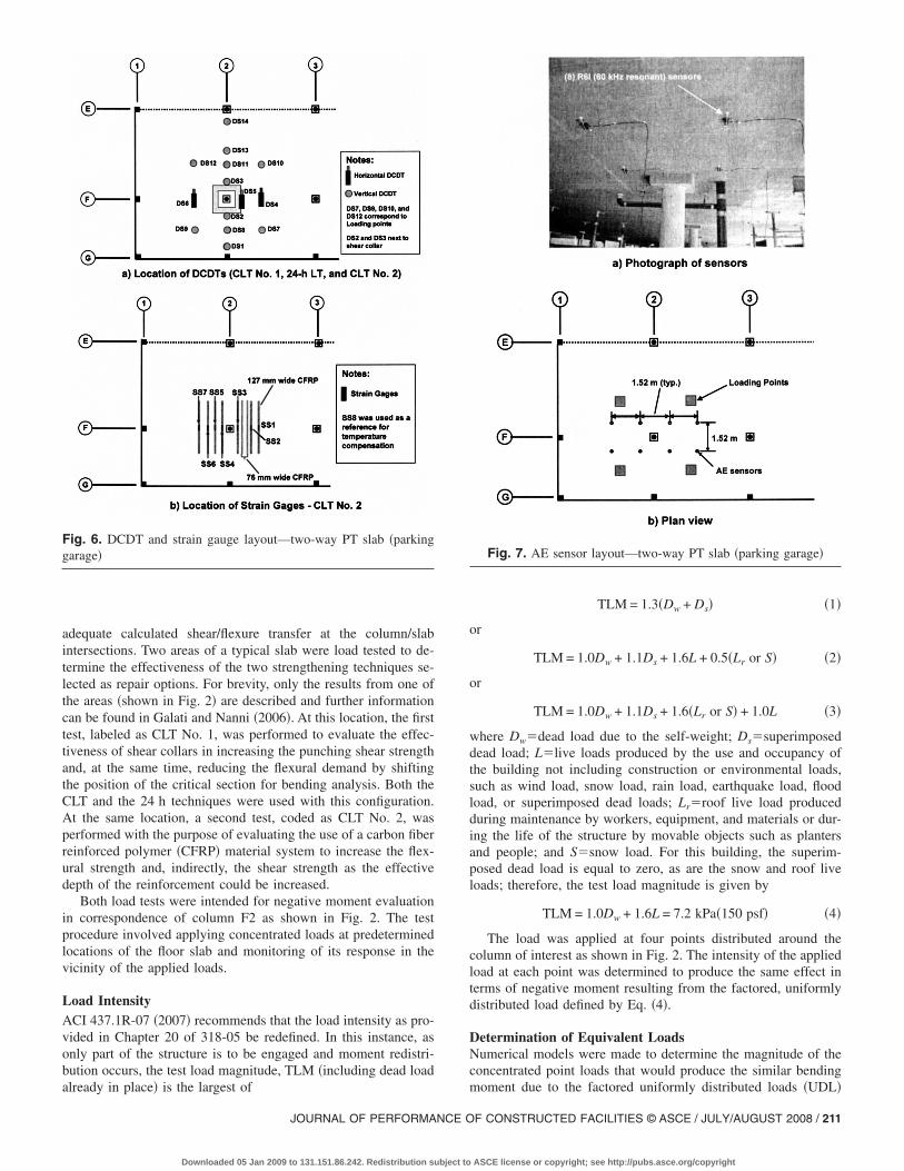
Fig. 6. DCDT and strain gauge layout—two-way PT slab �parkinggarage�
already in place� is the largest of
JOURNAL OF PERFORMANCE O
Downloaded 05 Jan 2009 to 131.151.86.242. Redistribution subject to
TLM = 1.3�Dw + Ds� �1�
or
TLM = 1.0Dw + 1.1Ds + 1.6L + 0.5�Lr or S� �2�
or
TLM = 1.0Dw + 1.1Ds + 1.6�Lr or S� + 1.0L �3�
where Dw�dead load due to the self-weight; Ds�superimposeddead load; L�live loads produced by the use and occupancy ofthe building not including construction or environmental loads,such as wind load, snow load, rain load, earthquake load, floodload, or superimposed dead loads; Lr�roof live load producedduring maintenance by workers, equipment, and materials or dur-ing the life of the structure by movable objects such as plantersand people; and S�snow load. For this building, the superim-posed dead load is equal to zero, as are the snow and roof liveloads; therefore, the test load magnitude is given by
TLM = 1.0Dw + 1.6L = 7.2 kPa�150 psf� �4�
The load was applied at four points distributed around thecolumn of interest as shown in Fig. 2. The intensity of the appliedload at each point was determined to produce the same effect interms of negative moment resulting from the factored, uniformlydistributed load defined by Eq. �4�.
Determination of Equivalent LoadsNumerical models were made to determine the magnitude of theconcentrated point loads that would produce the similar bending
Fig. 7. AE sensor layout—two-way PT slab �parking garage�
moment due to the factored uniformly distributed loads �UDL�
F CONSTRUCTED FACILITIES © ASCE / JULY/AUGUST 2008 / 211
ASCE license or copyright; see http://pubs.asce.org/copyright

212 / JOURNAL OF PERFORMANCE OF CONSTRUCTED FACILITIES © AS
Downloaded 05 Jan 2009 to 131.151.86.242. Redistribution subject to
at the critical test section. A two-dimensional model was im-plemented using commercial FEM software �Computers andStructures, Inc. 2000�. The model consisted of one-dimensional“beam elements” representing columns and a fine mesh of“plate elements” to represent the floor systems. The mate-rial properties of concrete were assumed to be isotropic and li-near elastic using a concrete modulus of elasticity equal toEc=57,000�fc��24.8 GPa �3.6�106 psi�. The presence of a flex-ural crack along line F was modeled by reducing the flexuralstiffness of the elements along this line. This assumption wasvalidated with the experimental results collected in the field. Themoment demands given in Table 1 were used as a reference forthe test setup design. Shoring posts to simulate the presence ofshear collars were used for CLT No. 1. After conducting CLT No.1, the 24 h test was performed for comparison of the two meth-ods. Table 2 summarizes the findings in terms of point loads �PLL�determined prior to testing. The equivalent point loads for Area 1in its original configuration are significantly lower than whenusing the shoring posts. This is because their presence modifiedthe static scheme of the structure �Fig. 3� by acting as an elasticsupport next to the locations where the moments were to be cal-culated, resulting in much lower loads for those tests in whichthey were used.
Load Testing and Measurement ApparatusFig. 4 shows an overall schematic of the push-down test. Shoringwas installed on one floor above the tested zone to provide con-trast for the hydraulic jacks. Wood bearing pads were used be-tween the spreader beams and the structural floor to protect theconcrete from localized damage.
�Vn
�kN �kip��Vu
�kN �kip�� Objective
469.7 �105.6� 301.1 �67.7� Evaluate performance of the slabto negative moments
g�
��Mu,test
�kN m �k ft��Vu,TLM
�kN �kip��Vu,test
�kN �kip��
6� 260.3 �191.4� 285.6 �64.2� 244.2 �54.9�
6� 260.4 �191.5� 285.6 �64.2� 232.6 �52.3�
Fig. 9. Load test area—two-way RC slab �building�
Table 3. Moment Capacity and Demand—Two-Way RC Slab �Building�
Location�Mn
�kN m �kip ft��Mu
�kN m �kip ft��
Level B, column strip defined by Line 12in correspondence of Column H
289.0 �212.5� 287.8 �211.6�
Table 4. Point Load �PLL� and Resulting Effects—Two-Way RC Slab �Buildin
Test labelPLL
�kN �kip��Strip width
�m �ft��Mu,TLM
�kN m �k ft
Load Line 1 126.3 �28.4� 3.20 �10.5� 259.2 �190.
Load Line 2 125.4 �28.2� 3.20 �10.5� 259.2 �190.
Fig. 8. Load cycles for the three tests—two-way PT slab �parkinggarage�
CE / JULY/AUGUST 2008
ASCE license or copyright; see http://pubs.asce.org/copyright

The equipment used consists of four 978.6 kN �220 kip�hydraulic cylinder jacks and pump, direct current differentialtransducers �DCDTs� for measuring deflections, two load cells�900 and 1,800 kN �100 and 200 kip��, and eight R6I acousticemission sensors �resonant in the vicinity of 60 kHz� �seeFig. 5–7�. A data acquisition system recorded values at a rate of1 Hz, displaying the load versus deflection curves in real time.Acoustic emission data were recorded separately with an eight-channel, two-high-speed-board system. Deflection measurementswere taken in 14 different locations. The layout of the DCDTs isshown in Fig. 6�a�. For CLT No. 2, a total of eight strain gaugeswere also placed on the CFRP reinforcement distributed in corre-spondence with the repaired cracks �Fig. 6�b��.
Because the slab was loaded in negative moment, the AEsensors were mounted on the compression face of the concreteslab �underside� in a grid pattern with outside dimensions of1.5�4.6 m �5�15 ft� centered on Column F2 �Figs. 7�a and b��.High vacuum grease was used as couplant and contact was main-tained with specially fabricated magnetic hold-down devices. Theevaluation threshold used was 45 dB. The wavespeed in the slabwas determined on-site based on time-of-arrival with pencil leadbreaks used as simulated acoustic emission sources.
Fig. 10. Negative moments generated by uniform dead load andconcentrated load—two-way RC slab �building�
Fig. 11. Schematic of the load test—two-way RC slab �building�
JOURNAL OF PERFORMANCE O
Downloaded 05 Jan 2009 to 131.151.86.242. Redistribution subject to
CLT Loading ProcedureFigs. 8�a–c� show the applied load cycles. The actual load cyclesmay vary slightly depending on the performance of the system asmonitored during the test and the minimum load that has to bemaintained to eliminate slack in the system. The applied loadcycles do not start from zero to account for the weight of thetesting equipment that was measured to be 360 kg �800 lb� perloading point. The 24 h load test profile is shown in Fig. 8�b�.
Two-Way Reinforced Concrete Slab in a BuildingStructure
This section describes one of two load tests performed on Level“B2” of a library building. The aim of the load test was to assessthe structural performance of the two-way RC slab system for theoriginal design loads by monitoring the negative bending momentcapacity. The selected area for the test is shown in Fig. 9.
Description of the StructureThe structural floor is a two-way slab supported by rectangularcolumns. The concrete slab is mostly 265 mm �10.5 in.� thick.The material characteristics indicated a nominal concrete strengthof 20.7 MPa �3,000 psi� and minimum steel yield strength of mildreinforcement of 275 MPa �40 ksi�. Further information can befound in Galati and Nanni �2007�.
Fig. 12. DCVT layout—two-way RC slab �building�
Fig. 13. Loading equipment—two-way RC slab �building�
F CONSTRUCTED FACILITIES © ASCE / JULY/AUGUST 2008 / 213
ASCE license or copyright; see http://pubs.asce.org/copyright

Load IntensityThe dead load was determined as the addition of the self-weightof the structure 193 Pa �130 psf� and a super imposed dead loadof 37 Pa �25 psf�. The live load is 186 Pa �125 psf�. The TLM asprescribed by ACI 318-05 �2005� was used
Fig. 14. AE sensor layout—two-way RC slab �building�
Fig. 15. Load cycles—two-way RC slab �building�
214 / JOURNAL OF PERFORMANCE OF CONSTRUCTED FACILITIES © AS
Downloaded 05 Jan 2009 to 131.151.86.242. Redistribution subject to
0.85�1.4D + 1.7L� = 543 MPa �365 psf� �5�
Table 3 lists the values of bending moment and punching shearcapacities of the existing slab and the factored forces due to thedesign loads. These values were determined for a column stripof 3.2 m �10.5 ft� width. In Table 3, �Mn and �Vn�existingslab bending and punching shear capacities and Mu andVu�factored bending and punching shear demands. The capaci-ties were calculated considering the material properties at thetime of the construction, without accounting for degradationover time. The reason for the load test was to verify if this as-sumption would hold as diffuse cracking was observed in theentire structure.
Determination of Equivalent LoadsNumerical models were implemented in order to determine themagnitude of the concentrated point loads that would produce thesame negative bending moments of the factored UDL at the criti-cal cross section as that caused by the design loads. A two-dimensional model consisting of beam elements representingcolumns and plate elements representing the slab was created andanalyzed with SAP 2000. Table 4 summarizes the findings interms of required point loads, PLL. The load PLL was applied ateach of four locations �Fig. 9�. At each point, the force was dis-tributed over a 300�300 mm �12�12 in.� area to avoid punch-ing through the slab. It was not possible to apply the loadsymmetrically with respect to Column H12 due to the presence ofpiping. For this reason, different loads were applied at the Load-ing Lines 1 and 2 �Fig. 9�. Fig. 10 shows the negative momentdistribution corresponding to the application of the UDL and tothe test loads, respectively.
Equipment and Measurement ApparatusThe load test was performed in a push-down method using aprocedure similar to the one used in the parking garage �Fig. 11�with shoring installed on one floor above to provide contrast.Deflection measurements were taken with DCDTs mountedon tripods supported on the level below the one being tested�Fig. 12�. The wires from the data acquisition system were takento the DCDTs through the air conditioning ducts. The testingequipment consisted of four 290 kN �66 kip� hydraulic cylinderjacks and two hydraulic pumps, DCDTs for measuring deflec-tions, and two load cells �450 and 900 kN �50 and 100 kip, re-spectively�� �Fig. 13�. A data acquisition system was set to recorddata at a rate of 3 Hz from all devices, providing real-time displayof collected data as well as the load versus deflection curves. Theacoustic emission data acquisition system was the same as that
Table 5. Experimental and Analytical Results CLT No. 1 �DS10�—Two-Way PT Slab �Parking Garage�
Loadcycle
�max
�mm �in.���max
�mm �in.�� �FEM�
1 1.735 �0.0683� 1.859 �0.0732�
2 1.770 �0.0697� 1.859 �0.0732�
3 2.626 �0.1034� 2.606 �0.1026�
4 2.657 �0.1046� 2.606 �0.1026�
5 3.426 �0.1349� 3.553 �0.1320�
6 3.485 �0.1372� 3.553 �0.1320�
7 3.995 �0.1573� 4.100 �0.1614�
8 3.975 �0.1565� 4.100 �0.1614�
used for the parking garage. Six sensors were distributed on a grid
CE / JULY/AUGUST 2008
ASCE license or copyright; see http://pubs.asce.org/copyright

with dimensions of 1.2�2.4 m �4�8 ft� centered on ColumnH-12 �Fig. 14�. The sensor coupling devices and evaluationthreshold were as described previously.
CLT Loading ProcedureThe testing procedure was conceptually similar to the one usedfor the parking garage. Once all instruments were connected, apreload was applied to seat the components and to eliminate slackin the system. Following that, the slab was loaded in eight cycles.Four steps for loading followed by two steps for unloading wereused. Each load step was maintained for at least 2 min. Fig. 15shows the applied load cycles for the tested areas. The maximumload reached in the first two cycles corresponds to the service loadlevel. The maximum load reached in Cycles 5 and 6 correspondsto the load combination suggested by ACI 437-06, whereas thelast two cycles corresponded to the load level prescribed by ACI318-05 Chapter 20 �2005�. The applied load cycles do not startfrom zero to account for the weight of the testing equipment thatwas measured to be 3.5 kN �800 lb� per loading point.
Model Validation
Good agreement between experimental and analytical results atthe service load level stages was observed in all cases.
Table 6. Experimental and Analytical Results CLT No. 2 �DS10�—Two
Loadcycle
�max
�mm �in.���max �mm �in.��
�FEM� uncracked
1 3.551 �0.1398� 3.503 �0.1379�
2 3.561 �0.1402� 3.503 �0.1379�
3 5.751 �0.2264� 4.704 �0.1852�
4 5.773 �0.2273� 4.704 �0.1852�
5 9.365 �0.3687� 6.287 �0.2475�
6 9.903 �0.3899� 6.287 �0.2475�
7 13.005 �0.5120� 7.447 �0.2932�
8 13.391 �0.5272� 7.447 �0.2932�
9 16.787 �0.6609� 8.288 �0.3263�
10 17.760 �0.6992� 8.291 �0.3264�
Fig. 16. Cycles deflection diagram for CLT No. 2—two-way PT slab�parking garage�
JOURNAL OF PERFORMANCE O
Downloaded 05 Jan 2009 to 131.151.86.242. Redistribution subject to
Two-Way PT Concrete Slab
Table 5 shows a comparison between the experimental and thetheoretical results at the most demanding location �DS10� forCLT No. 1. The model fits well the experimental results for CLTNo. 1 as the behavior of the structure was elastic with no residualdeflection measured when the load was removed. In fact, no newcracks were observed when performing the cyclic load test; theeffect of the applied loads was mostly to increase the size of theexisting cracks.
For CLT No. 2 the preexisting crack was repaired �filled bygravity feed of epoxy� before installing the FRP strengtheningand, therefore, two models were considered: cracked and un-cracked. Table 6 shows a comparison between numerical and ex-perimental results at the location monitored by DCDT DS10 forCLT No. 2. These results indicate that deflection predictions forthe uncracked slab condition matches well the first four cycles.The measured deflection is closer to the calculated deflectionbased on a cracked slab condition, accounting for permanency, forthe later cycles �Fig. 16�.
Two-Way RC Slab
Table 7 compares the FEM predictions with the experimental re-sults recorded during the load test. The cracking of the slab wasintroduced in the model as a smeared cracking as the location ofthe existing cracks and crack formation was not known. Theseresults indicate that deflection prediction for the uncracked slabcondition matches the first two cycles, whereas the measured de-flection is closer to the calculated deflection based on a cracked
T Slab �Parking Garage�
�max �mm �in.���FEM� cracked
�max �mm �in.���FEM� cracked+permanency
5.865 �0.2309� 5.865 �0.2309�
5.865 �0.2309� 5.865 �0.2309�
7.877 �0.3101� 7.899 �0.3110�
7.877 �0.3101� 7.899 �0.3110�
10.526 �0.4144� 10.526 �0.4144�
10.526 �0.4144� 11.064 �0.4356�
12.466 �0.4908� 13.005 �0.5120�
12.466 �0.4908� 13.391 �0.5272�
13.876 �0.5463� 16.607 �0.6538�
13.879 �0.54646� 17.579 �0.6921�
Table 7. Experimental and Analytical Results �DS12�—Two-Way RCSlab �Building�
Loadcycle
�max
�mm �in.���max �mm �in.��
�FEM� uncracked�max �mm �in.���FEM� cracked
1 0.836 �0.0329� 0.838 �0.0330� 1.224 �0.0482�
2 0.869 �0.0342� 0.838 �0.0330� 1.224 �0.0482�
3 1.196 �0.0471� 1.054 �0.0415� 1.542 �0.0607�
4 1.237 �0.0487� 1.054 �0.0415� 1.542 �0.0607�
5 1.656 �0.0652� 1.247 �0.0491� 1.824 �0.0718�
6 1.699 �0.0669� 1.247 �0.0491� 1.824 �0.0718�
7 1.984 �0.0781� 1.389 �0.0547� 2.035 �0.0801�
8 2.080 �0.0819� 1.389 �0.0547� 2.035 �0.0801�
-Way P
F CONSTRUCTED FACILITIES © ASCE / JULY/AUGUST 2008 / 215
ASCE license or copyright; see http://pubs.asce.org/copyright

slab condition for the last two cycles �Fig. 17�. The slab started tocorrelate better with the theoretical cracked slab behavior at thethird cycle. The effect of the permanency was not considered as itwas negligible compared to the recorded deflections.
Conclusions
This paper presented the loading procedure to conduct a CLTin-situ evaluation of two facilities: a posttensioned parking garagefacility and a library. For both structures, the load test was con-ducted without disrupting the normal operation of the facilities.
FEM models were created for both structures and were wellcorrelated with experimental observations. The selection of testload magnitude and the use of point loads to simulate distributedloading effects are described in detail.
Both case studies represented the ideal test bed for the CLTprocedure due to its inherent safety. In fact, both structures, onedeficient due to misplacement of posttensioning tendons and theother with diffuse cracking, could have presented safety hazards.
Acknowledgments
The ACI Concrete Research Council, the NSF Industry/University Cooperative Research Center on Repair of Buildingsand Bridges with Composites and the UMR–University Transpor-tation Center on Advanced Materials are gratefully acknowledgedfor their financial support to the research. Yizhuo Chen assistedwith the load tests and data reduction and his assistance is greatlyappreciated.
References
American Concrete Institute �ACI�. �1920�. “Standard building regula-tions for the use of reinforced concrete,” Standard Specification No.23, Detroit.
American Concrete Institute �ACI�. �1936�. “Building code regulationsfor reinforced concrete.” ACI 501-36T, Detroit.
Fig. 17. Cycles deflection diagram—two-way RC slab �building�
216 / JOURNAL OF PERFORMANCE OF CONSTRUCTED FACILITIES © AS
Downloaded 05 Jan 2009 to 131.151.86.242. Redistribution subject to
American Concrete Institute �ACI�. �2004�. “Strength evaluation ofexisting concrete buildings.” ACI 437R-03, ACI Committee 437,Farmington Hills, Mich.
American Concrete Institute �ACI�. �2005�. “Building code requirementsfor structural concrete.” ACI 318–05, Farmington Hills, Mich.
American Concrete Institute �ACI�. �2007�. “Test load magnitude, proto-col and acceptance criteria.” ACI 437.1R-07, ACI Committee 437,Farmington Hills, Mich.
ASME. �2004a�. “Section V—Nondestructive examination.” Boiler andpressure vessel code, New York.
ASME. �2004b�. “Section X—Fiber-reinforced plastic pressure vessels.”Boiler and Pressure Vessel Code, New York.
ASTM. �2006�. “Standard terminology for nondestructive examinations.”ASTM E 1316 06a, West Conshohocken, Pa.
Birkmire, W. �1894�. Skeleton construction in buildings, Wiley, NewYork.
Bungey, J. �1989�. The testing of concrete in structures, 2nd Ed., Chap-man and Hall, New York.
Casadei, P., Parretti, R. Nanni, A. and Heinze, T. �2005�, “In-situ loadtesting of parking garage RC slabs: Comparison between 24-h andcyclic load testing.” Pract. Period. Struct. Des. Constr., 10�1�, 40–48.
Computers and Structures, Inc. �2000�. SAP 2000, Version II, Berkeley,Calif.
FitzSimons, N., and Longinow, A. �1975�. “Guidance for load tests ofbuildings.” J. Struct. Div., 101�7�, 1367–1380.
Galati, N., Casadei, P., Lopez, A., and Nanni, A. �2004�. “Load testevaluation of Augspurger ramp parking garage, Buffalo, N.Y.” Rep.No. 04-50, Center for Infrastructure Engineering Studies, Univ. ofMissouri-Rolla, Rolla, Mo.
Galati, N., and Nanni, A. �2006�. “Load testing of two post-tensionedconcrete slabs at garage A. Windsor on the Plaza, Kansas City, Mo.”Final Rep., Prepared for Simpson Gumpertz & Heger Inc., Univ. ofMissouri-Rolla, Rolla, Mo.
Galati, N., and Nanni, A. �2007�. “In-situ structural evaluation of a two-way RC slab at the National Institute of Health, Bethesda, Maryland.”Final Rep., Prepared for Simpson Gumpertz & Heger Inc., Univ. ofMissouri-Rolla, Rolla, Mo.
Gold, W. J., and Nanni, A. �1998�. “In-situ load testing to evaluate newrepair techniques.” Proc., NIST Workshop on Standards Developmentfor the Use of FRP for the Rehabilitation of Concrete and MasonryStructures, Tucson, Ariz., NISTR 6288, D. Duthinh, ed., Feb. 1999,3-102/112.
Mettemeyer, M., and Nanni, A. �1999�. “Guidelines for rapid load testingof concrete structural members.” Rep. No. 99-5, Center for Infrastruc-ture Engineering Studies, Univ. of Missouri-Rolla, Rolla, Mo.
Nanni, A., and Gold, W. �1998a�. “Evaluating CFRP strengthening sys-tems in-situ.” Concrete Repair Bull., Int. Concrete Repair Ins., 11�1�,12–14.
Nanni, A., and Gold, W. J. �1998b�. “Strength assessment of external FRPreinforcement.” Concr. Int., 20�6�, 39–42.
NDIS 2421. �2000�. “Recommended practice for in situ monitoring ofconcrete structures by acoustic emission.” Japanese Society for Non-Destructive Inspection.
RILEM Technical Committee 20-TBS. �1984�. “General recommendationfor statical loading test of load-bearing concrete structures in situ�TBS2�.” RILEM technical recommendations for the testing and useof construction materials, E & FN Spon, London, 379–385.
Ziehl, P. H., Galati, N., Nanni, A., and Tumialan, J. G. �2008�. “In situevaluation of two concrete slab systems. II: Evaluation criteria andoutcomes.” J. Perform. Constr. Facil., 22�4�, 217–227.
CE / JULY/AUGUST 2008
ASCE license or copyright; see http://pubs.asce.org/copyright