in approved - vtechworks.lib.vt.edu · be = effective compressive flange width of t-beam ... icr =...
TRANSCRIPT

‘II
xr?BY
Feasibility Of Fiber Reinforced Composite Materials
Used In Highway Bridge Superstructures
byShih-Yung Lin
Thesis submitted to the Faculty of the
Virginia Polytechnic Institute and State University
in partial fulfillment of the requirements for the degree of
Master of Science
in
Engineering Mechanics
APPROVED:
O. H. Gräééin, Er.?
,%/77 6„„»Al/ ‘ ~;7""M‘R. M. Barker rdal
December, 1988
Blacksburg, Virginia

Feasibility Of Fiber Reinforced Composite Materials I
Used In Highway Bridge Superstructures
byShih-Yung Lin
O. H. Griffin, Jr.
Engineering Mechanics
(ABSTRACT)
Composite materials are considered here as structural
materials of highway bridge superstructures. Bridge deck de-
signs can be done according to AASHTOI specification and
_äi_ elastic design concepts.
bjQäg In order to evaluate the feasibility of composites as
structural materials of highway bridge superstructures, com-
posite materials are compared not only to composite materials
themselves but also to the most popular bridge structural
materials, which are reinforced concrete and structural
steel.
The AASHTO1 HSZO-44 truck load is selected as the standard
loading condition of all designs. Loads other than dead load
and live load are not considered. Configurations of the
bridges are different. Appropriate cross-section of girders
are selected according to the material types. For fiber re-

I I
III
inforced composite materials, box girder is used, for rein- Iforced concrete, T-beam is selected; in addition, steel
concrete composite section is another case.
Design methods are different from material to material.
Reinforced concrete T-beam design is based on the 'Ultimate
Strength Design' method. Steel concrete composite sections
are designed according to the 'Load & Resistance Factor De-
sign'. For composite materials, 'Elastic Design' is se-
lected.
The results derived are as expected. Substantial weight
saving is achieved by simply replacing concrete or steel with
composite materials. This also results in many other advan-
tages such as construction time, cost, foundation settlement
and support requirements.

I
EIABLE OF CONTENTS I
CHAPTER 1 Introduction ................. 1
CHAPTER 2 Literature Review .............. 5
2-1 Current Highway Bridge Deck Structure ...... 5
2-2 AASHT0 Specification ............... 5
2-3 Ultimate Strength Design (USD) .......... 6
2-4 Load & Resistance Factor Design ...,..... 7
CHAPTER 3 Design of Concrete T-beam Bridge Decks .... 9
3-1 Ultimate Strength Design (USD) ......... ll
3-2 Thickness of Concrete Slab ........... 11
3-3 Dimension of T-beam .............. 13
3-4 Deflection ................... 14
3-5 Design Procedures ............... 15
3-6 Design Example ................. 20
3-7 Weight of Structure .............. 29
CHAPTER 4 Steel-Concrete composite Section ...... 32
4-1 Load & Resistance Factor Design (LRFD) ..... 34
4-2 Thickness of Concrete Slab ........... 35
4-3 Dimension of W-section ............. 35
4-4 Deflection ................... 36
Table of Contents iv

4-5 Design Procedures ............... 37
4-6 Design Example ................. 40
4-7 Weight of Structure .............. 45
CHAPTER 5 Composite Material Bridge Deck ....... 47
5-1 Elastic Design ................. 47
5-2 Material Properties .............. 49
5-3 Deflection ................... 50
5-4 Floor Beam Design ............... 50
5-5 Girder Design ................. 55
5-6 Best Design .................. 56
5-7 Design Example ................. 57
5-8 Weight of Structure .............. 64
CHAPTER 6 Results and Discussion ........... 68
6-1 Characteristics of Design ........... 68
6-2 Weight of Three Design Models. ......... 70
6-3 Maintenance and Repair ............. 71
6-4 Construction Methods .............. 73
6-5 Fatigue .................... 74
6-6 Shrinkage and Thermal Effects ......... 75
6-7 Deflection ................... 76
6-8 Cost ....'.................. 77
CHAPTER 7 summary and Conclusion ........... 80
Table of Contents v
Appendix A. Maximum live load moments and shears . . . 82
Appendix B. Results Of Composite Material Floor Beam De-
sign ......................... 83
Appendix C. FORTRAN PROGRAM "DECK" .......... 88
Appendix D. Results of girder design ......... 95
References ...................... 100
Table of Contents vi

r
LISI OF ILLUSIgATIO§S
Figure 1. Design Model ................. 3
Figure 2. Typical Cross Sections Of Concrete Beams . . . 6
Figure 3. Assumed Stress Distribution of USD ...... 7
Figure 4. T-beam Design Model ............ 10
Figure 5. Strip Design Method ............ 12
Figure 6. Simplified HS20-44 Truck Load ....... 15
Figure 7. Determination of Girder Height ....... 17
Figure 8. Deflection Calculation of T-beam ...... 28
Figure 9. Approximate Weight of T-beam ........ 31
Figure 10. Typical Cross Section of Steel—Concrete Com-posite Section ............... 32
Figure 11. Cross Section Considered for Steel-ConcreteBeam Design ................ 34
Figure 12. Equivalent Steel Cross Section ....... 37
Figure 13. Illustration of Steel-Concrete Composite BeamDesign ................... 40
Figure 14. Weight Curve of Steel-Concrete Composite Beams 46
· Figure 15. Composite Material Bridge Deck ....... 48
Figure 16. Dimension of Floor Beam .......... 51
Figure 17. Live Load on Floor Beams .......... 52
Figure 18. Simplified Design Models .......... 54
Figure 19. Design Example of Floor Beam ........ 61 !Figure 20. Weight of Floor Beam vs. Girder Width . . .
62Figure21. Design Results ( DEPTH vs. WEIGHT ) .... 65I
Figure 22. Weight Curves of Composite Material Design . 66 g
¥List of Illustrations vii ‘

I
Figure 23. Weight of Designs ............. 72
Figure 24. Deflection of Three Design Models ..... 78
II
List of Illustrations viii

LIST OF TABLES
Table 1. Results Of T-beam Design .......... 30
Table 2. Results Of Steel—Concrete Composite Beam Design 45
Table 3. Composite Material Properties ........ 49
Table 4. Weight of Designs (lb/foot/lane) ...... 71
Table 5. Factors Affecting The Cost Of Bridges .... 79
Table 6. The Maximum Moment and Shear of Highway Bridges,HS20-44 Truck, ............... 82
Table 7. Floor Beams of T300/5208 Graphite/Epoxy . . . 83
Table 8. Floor Beams of B(4)/5505 Boron/Epoxy .... 84
Table 9. Floor Beams of AS 4/3501 Graphite/Epoxy . . . 85
Table 10. Floor Beams of Scotchply 1002 Glass/Epoxy . . 86
Table 11. Floor Beams of Kevlar 49/Epoxy ....... 87
Table 12. T300/5208 Graphite/Epoxy .......... 95
Table 13. B(4)/5505 Boron/Epoxy ............ 96
Table 14. AS 4/3501 Graphite/Epoxy .......... 97
Table 15. Scotchply 1002 Glass/Epoxy ......... 98
Table 16. Kevlar 49/Epoxy ............... 99
List of Tables ix

JJNOTAIIONS J
a = depth of equivalent rectangular stress block
A = cross sectional area
Ac = concrete area
AS = area of nonprestressed tension reinforcement
Asf = area of reinforcement to develop compressive
strength of overhanging flanges of T-sections
Aw = web area of steel beam
B = width of girder
b = unit width in strip design of concrete slab
bE = effective compressive flange width of T-beam
bf = flange width of steel beam
bw = web width
c = distance from extreme fiber to neutral axis
Cb = distance from extreme bottom fiber to neutral axisJ Ct = distance from extreme top fiber to neutral axis
d = effective depth
D = dead load
Dg = depth of composite material girder
Eb = modulus of elasticity of concrete
ES = modulus of elasticity of reinforcement
El = elastic modulus of composite materials in fiber
direction
Notations x

1E2 = elastic modulus of composite materials
perpendicular to fiber direction
fg = specified compressive strength of concrete
FD = dead load factor
FL = live load factor
fr = modulus of rupture of concrete
fy = specified yield strength of reinforcement
h = overall height
hf = compressive flange thickness of T-sections
I = impact effect
Icr = area moment of inertia of cracked sectiontransformed to concrete
Ie = effective area moment of inertia for computation of
deflection
fg = gross area moment of inertia of concrete section
Ix = area moment of inertia of section
L = live load
Ma = maximum moment in member at the stage for which
deflection are being computed
Mer = cracking moment
MD = dead load moment
ML = live load moment
Mn = nominal moment strength
MR = required moment strength
Mu = moment due to factored loads
Notations xi
I
I
n = modulus ratio
Q = static moment for a point in the cross section
Qmm{= maximum static moment
ZQR = nominal shear strength of shear connectors
R = design load carrying capacity
S = clear span of girder
S = shear strength of composite material
s = clear span of floor beam or concrete slab
T = thickness of composite material girder
ts = slab thickness
tw = web thickness
U = required strength to resist factored loads
VC = nominal shear force carried by concrete
VD = dead load shear force
VL = live load shear force
Vu = nominal shear strength
VR = required shear strength
VS = nominal shear strength provided by shear
reinforcement
Vu = factored shear force at section
W = wind load
WD = distributed dead load
WS = weight of steel beam
WT = estimate weight in steel-concrete composite
section design
Notations xii
x = depth of neutral axis
XC = compression strength in x-direction of composite
materials
XC = tension strength in x-direction of compositeX
materials
x' = centroid location of concrete cross section
YC = compression strength in y-direction of composite
materials
distance from top of steel beam to top of concrete
Yt = tension strength in y-direction of composite
materials
Y;q,= distance from centroid of cross section to ‘
extreme fiber in tension, neglecting reinforcement
Y; = distance from concrete flange force to beam top
flange
ßl = ratio of depth of rectangular stress block,
a, to depth of neutral axis.
ÖL = deflection due to live load
maximum allowable deflection
¢ = strength reduction factor
¢ = analysis factor Ip = steel ratio
pb = balanced steel ratio_ Asf
Pf —· jäijpmm,= allowable maximum steel ratio
i Notations xiii

11pmÜ1= allowable minimum steel ratio 1Gb = stress at bottom fiber6m„;= maximum stressat = stress at top fiber
1 = shear stress
·%mx = maximum shear stress
1Notations xiv
111
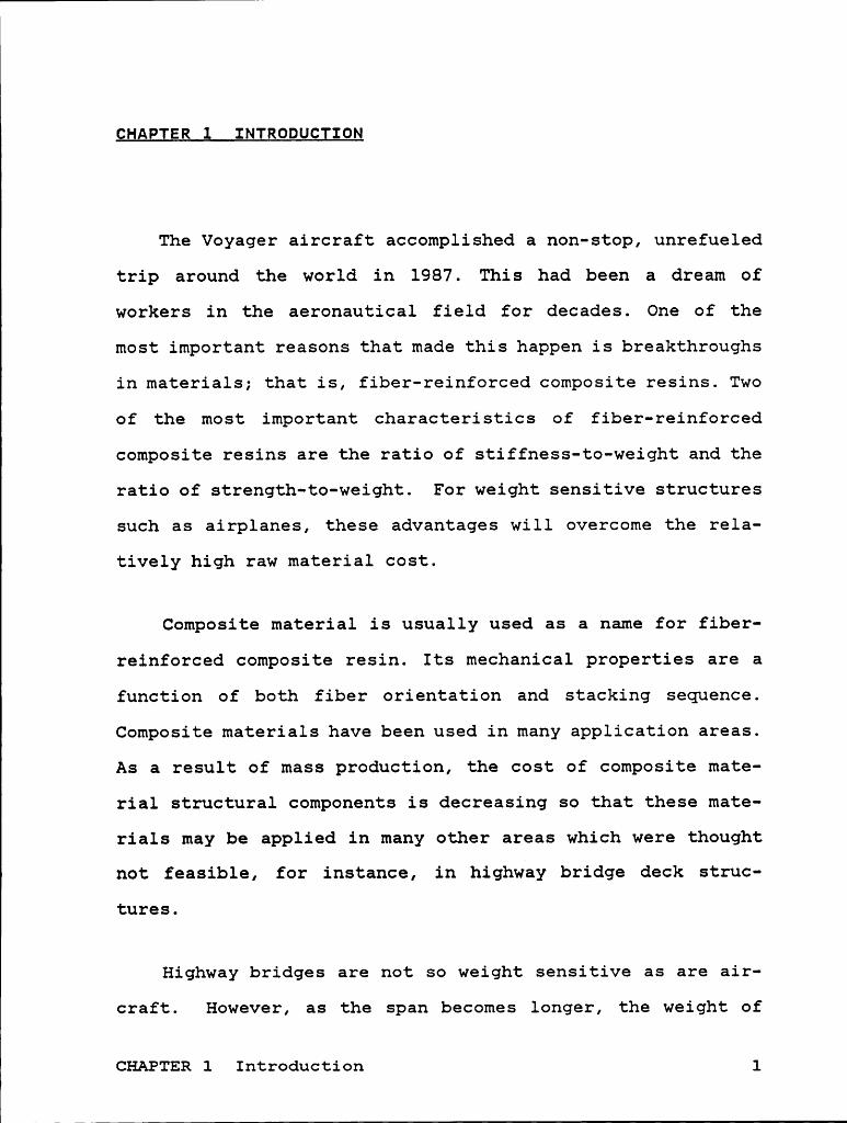
CHAPTER 1 INTRODUCIION
The Voyager aircraft accomplished a non-stop, unrefueled
trip around the world in 1987. This had been a dream of
workers in the aeronautical field for decades. One of the
most important reasons that made this happen is breakthroughs
in materials; that is, fiber-reinforced composite resins. Two
of the most important characteristics of fiber-reinforced
composite resins are the ratio of stiffness-to-weight and the
ratio of strength-to-weight. For weight sensitive structures
such as airplanes, these advantages will overcome the rela-
tively high raw material cost.
Composite material is usually used as a name for fiber-
reinforced composite resin. Its mechanical properties are a
function of both fiber orientation and stacking sequence.
Composite materials have been used in many application areas.
As a result of mass production, the cost of composite mate-
rial structural components is decreasing so that these mate-
rials may be applied in many other areas which were thought
not feasible, for instance, in highway bridge deck struc-
tures.
Highway bridges are not so weight sensitive as are air-
craft. However, as the span becomes longer, the weight of
CHAPTER 1 Introduction 1
load carrying structures such as beams and supports increases
dramatically. Foundation, requirements are also increased
with the increasing span, and foundation settlement may be-
come a problem. If the total structural weight can be re-
duced, a highway bridge built on a weaker foundation may be
appropriate.
Three different bridge deck configurations considered in
this study are concrete T-beam, steel-concrete composite
section, and composite material bridge deck. The first and
second configurations are the most commonly used in highway
bridge superstructures. The third will be investigated, in
several aspects, to evaluate the feasibility of using com-
posite materials to replace concrete and steel.
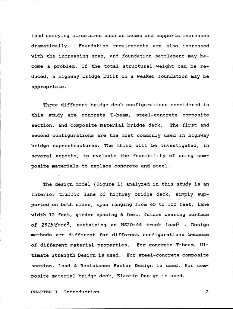
The design model (Figure 1) analyzed in this study is an
interior traffic lane of highway bridge deck, simply sup-
ported on both sides, span ranging from 40 to 100 feet, lane
width 12 feet, girder spacing 6 feet, future wearing surface
of 25lb/footz, sustaining an HS20-44 truck loadl . Design
methods are different for different configurations because
of different material properties. For concrete T-beam, Ul-
timate Strength Design is used. For steel-concrete composite
section, Load & Resistance Factor Design is used. For com-
posite material bridge deck, Elastic Design is used.CHAPTER 1 Introduction 2
I
.-EZ:-. .-:=:ZE¥:·. ,·;:¢E{:¢:-:-. „;;-5;;%-.__ÄE¢:·;:§:Z;§:§:;._._.;:;:§:§:§:'·'·'·.;.;:§:;:{:;:Z5§:'·';*·?cZ?‘:-:Z':*"“":§9Z' °"r§QE§:§Ä° {E32?}.
,-6 •+ f£•;•·{’ .44-,».-.« .·.-.-.·„.·.-«.« -----—:——-.6·""Ö,··z§ .·’·"x 4: :,-,4444-i?_.g·=;=;·;;; _»;»:Q-j¤{Ö;E_QE;;‘ii:~. ..-V
V. ‘ " i ~ . . ·. ‘~ _;S;Z;1;1;2;3;' -1-:·· :-:·:-:-·-:-··-:· :;:;z;:;:;:;:;:·'_.
•' '-' -'•§·f·:·:·§-§·§«::;·
..3 7 = :;:;:%:1; l.._........— ·¢' : .¤§’ ·= : ·-;;=;¢=;:£=E=E¢. O .. .::::;:»_____._ :c_:„;;_:_:_:; N.. _.'1
A2EäV p'{lfQ;g€Q VL:.=ig*j·f_;:.;ljL_;:“;_;E§_§;§i·‘;-3;’V;.j;;.»j·¢· ‘··:; Q.;;..1·’?t13mm$2S$·",gg
,__5-:-:-:·1-:·:·:·:·:-:·.»:·:·>·.·:·:·:·:·:;:·L;22_ _‘——————“_..._.. ——l————._..l....._ E ; ey
;:{ - :{ ;: : . 5;::5; E; {Ü ;:¥' ‘ E?EEE ‘ ä’ =‘ ¤° E 2 ‘
IZ............,..........Z
6 feet<——- Interior Traffic Lane
2:·
··:-:~:-Ü·w-:Z§5:{:—;·—:—:·:·:~:~ .........$=;x~=;·*·-*;:=$=;¤.ä;§?R„=·;$E=E=;=;=;=;=%;=;=éa=;=;2=·=‘*‘·‘·‘·=:=:=:=:=:=E=40
to l00 feet Simply Supported
Figure 1. Design Model
CHAPTER 1 Introduction 3

The aspects evaluated for the three configurations are
total weight of structure, maintenance, construction method,
fatigue behavior, shrinkage and thermal effects, deflection,
and cost.
I
CHAPTER 1 Introduction 4

CHAPTEB 2 LITEgATUR§ REvIEg
g-; Curgegg äighway Bridge gecg gtggcgurg
Currently, most bridge deck structures are reinforced
concrete cu: steel-concrete composite. For reinforced con-
crete, cross sections as shown in Figure 2 are typical. It
is apparent that the T-beam configuration will save some
weight because there is no cross-sectional area under the
flange. All the tensile stress is considered to be taken by
the steel reinforcements. In spite of this, reinforced con-
crete structure suffers from large dead load, especially as
the span increases. Prestressed concrete may be considered
as an alternative. It is good for longer span bridges, but
costs more in construction. Steel-concrete composite struc-
tures are also widely used in bridge deck systems, but con-
stant maintenance is required to prevent corrosion of the
steel beams.
The American Association of State Highway and Transpor-
tation Officials (AASHTO) published Standard Specification
CHAPTER 2 Literature Review 5

·j·j CONCRETE j· Z·Z·Z·I CONCRETE Iijijij
.:.:3:.;.*.*.*.** ^ ^Q Steel Bars — Ü ÜÜ^Ü^Ü^Ä^Ä^:^Ä
Rectangular Beam T·b€·@m
Figure 2. Typical Cross Sections Of Concrete Beams
for Highway Bridges, which serves as a rule in the highway
bridge design and construction.
g-3 Ultimate Strengtg Desigg (USD)
The Ultimate Strength Design (USD) method is established
by introducing plastic design concepts into the design cri-
terion. The basic concept of the USD is the assumption that
the stress distribution in the compressive zone of the beams
is rectangular as shown in Figure 3. For safety reasons,
under-reinforced beam (steel reinforcement yields before
concrete crushes) is used in the USD since steel provides l
large ductility that allows large deflection before failure.lCHAPTER 2 Literature Review 6 ‘

CONCRETE T-beam Compression pEriririr ;:E:ErE¤E:;- E:E=;:;¤
‘ I a 'XäääääääääzäE d J- -J~w¤J—IÄIÄIQIIÄIÄ I HHISriräriräriri E LI .Tension
Steel Reinforcements
Figure 3. Assumed Stress Distribution of USD
Z-9 Loag Q ßegisgggcg Eactog Design
American Institute of Steel Construction (AISC3) pub-
lished the Manual of Steel Construction - Load & Resistance
Factor Design, which provides an alternative method for the
design of beam and girder structures. It is the most recent
design criterion for the steel construction. In the current
AASHT01 specification, Load Factor Design is also an alter-
native approach to the elastic design method. The designJ
method is based on the requirement that ultimate strength I
CHAPTER 2 Literature Review 7 J
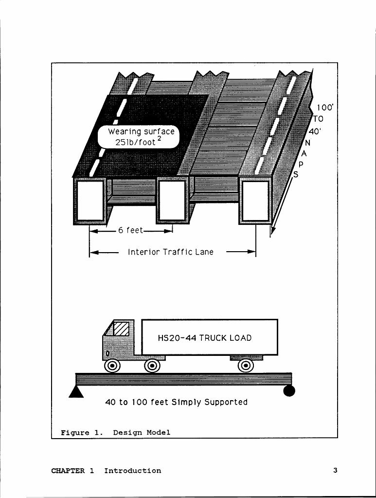
must be greater than factored loads. The general form of Load
Factor Design is
¢>R2Tß(FDxD+FLxL) (2.4.1)
Essentially, it is a limit state design method. The limiting
conditions such as overloading and failure are specified.
T
CHAPTER 2 Literature Review 8T

LC§APIEg 3 DESIGN OF CONCRETE T-BEAM BRIDGE DECKS
For reinforced concrete bridges, T-beam design is the most
popular structural configuration that has been used. In most
cases, T-beam bridge design is as easy as rectangular beam
design because the compression area provided by T-beam is so
large that it is usually capable of resisting the applied
bending moments even though the cross-sectional areas under
the flanges are omitted. In addition, due to reduction in
weight, requirements on load carrying capacity of beams and
supports are reduced. Construction costs are generally lower
than for rectangular beams.
In this chapter, a design sequence will be followed to
derive the approximate weight for a concrete T-beam with span
from 40 feet to 100 feet. AASHTOl specification is used. The
design model considered here is a simply supported bridge
span, T-beam spacing (center to center) of 6 feet and con-
tinuous in the transverse direction. Future wearing surface
of 25lb/footz is added on top of beams as shown in Figure 4.
;
CHAPTER 3 Design of Concrete T-beam Bridge Decks 9

AAAAA
IJ,
AAAAAAAAAAAAAAAAAAAAAA
AQ}.
u
AAAAA
AAAA-·_-
IAAAAA
AAAAAA
AAAAAI
AAAAAAAAAAAAAAAAAAA
I
AAAAAAAI
5555 ·
5555555F
555
5555555
T
5555555
a
555555
IC
5555555
L
L
an
AAAAAAA
•-
°i„fst
:::::.
zi,
e
09
555555
59
Iem
“IZIII
“IIZZI.;W
Q
55555
5g
Q
nC
U
Bt
H
Buzäiäx"
AAAAA
AAAAA
zziizzu
55555
_4
55555
·
55555
AAAAA
AAAA
55555
5
1
·l
AAA I
gu
I O
T
^ ^ I
1:
0
R
I
B
G
TE
T
t SI
LO A
3
G a
D I
lx:
m
YD
D
S
es.
es
Up
1
1
i
pB Q
gn
gn
Or
6
0
te BY
6
M
d
5
C
00
9¤B
1
B —_
rete T'b
eamB
r1dge DeckS 10

11° 1
3-1 Ultimate Strength Desigg (USD)
Considering the uncertainty of nmterial strength, a
strength reduction factor ¢> is normally included. AASHTO1
(8.16.1.2.2) suggests that the ¢ value for moment is 0.9 and
for shear is 0.85. In highway bridge superstructure design,
the impact effect should also be included. In this work, any
load except live load, dead load, and impact effect is ig-
nored. The factored loading according to AASHTOI (3.22) is
determined by
¢>R=1.3x(D+l.67><L(l+I)) (3.1.1)
where R is the design load carrying capacity of members.
3-g Thickness of Cogcrete Slab
The slab thickness will be dominated by two factors, the
transverse load resistance requirement and longitudinal load
resistance requirement. The larger slab thickness from the
two calculations will be taken as the minimum requirement.
In the transverse direction, the slab is designed by
taking a unit width (one foot) of the slab as a rectangular
beam. This is called the Strip Design Method (Figure 5). In
CHAPTER 3 Design of Concrete T-beam Bridge Decks ll

I
I
1I
I
Continuity factor of 0.8 is applicable to loads.
.·:¢:i:¥:¥:¢:¥:¤:¢:¢:¥:¤:¥:¥:¤:¥:¥:¢:¤:¥:¢:¢:¢:¥:¤:¥:¢:¢:¤:¢:¢:¢:¢:¢:¥:¢:¢:¢:=:¥:¢:=:¥:¢:¤:¤:¥:¥:ZS:¥:¢:¢:¢:¢:¥$5:¢:¥:¢:¢:¢:¥:¥:¢:¥:’•=:¤·‘.,.;:§:§:§:§:§:§:§:§:§:§:¢:¢:¢:¥:¢:¢:¥:¢:¢:¢:¢:¢:¢:¢:¢:¢:¥:¢:¢:¢:¢:¥:¢:¢:¢:*:*5:¢:¢:¥:¥:¢:*5:*:¢:¢:¢:¢:¥:¢:¢:¢:¢:¥:¢:¢:¢:¢:¢:¢:¢:¢:ig§;·.;$:€§.·;•.•.•.•.•.•.•.•.•.•.•.•:Z•I•I•Z•I•Z~I•I•I•I•Z•Z•I·Z•I•I•I•I•I•Z+i•I•Z•Z•I•I•I•I•Z•I•Z•I•I•Z•Z•I•I•Z•Z¢Z»I¢I•Z•I+Iv2•Z•I•Z•I•I•I•IvZ•°* °$•’;§/•_O
^A~A^A^A^hA*A^A*A^A—:·¤·
%ßFigure5. Strip Design Method
the longitudinal direction, the required slab thickness is
designed together with moment resistance of T-beam.
The slab designed for bending moment in accordance with
AASHTOl (3 . 24 . 3), distribution of wheel loads i s considered
satisfactory ixx shear (AASHTO1 3.24.4). Therefore, shear
capacity was not checked in this effort.
CHAPTER 3 Design of Concrete T-beam Bridge Decks 12

1
3-3 Dimension of T-beam
The effective flange width of T-beams is determined, ac-
cording to AASHTOI (8.10.1), by ·
bE S longitudinalspanbg
S spacing of T-beam (3.3.2)
bg S 12><slab thickness (3.3.3)
The web width must be at least capable of (1). embedding
an appropriate number of steel reinforcements used in the
longitudinal direction, (2). including two times the diameter
of shear reinforcements and (3). adding 1.5 inches on both
sides for protection of steel reinforcements.
According to AASHTOI (8.16.6.2.1), the shear capacity of
concrete is Vc=2./fc'b„d, and from AASHT0l (8.16.6.3.9), the
shear capacity of shear reinforcements is limited as
Vs S 8 ./fc' bwd. Shear design is omitted here because the shear
capacity normally does not affect the weight of T-beam design
except that the shear force needed to be taken by shear re-
inforcements exceeds the value discussed above. However,
shear resistance of concrete is checked instead and must be
CHAPTER 3 Design of Concrete T-beam Bridge Decks 13

greater than 20% of the shear load to avoid the situation
described.
§—9 Deflectiog
AASHTO1 does not give a definite value of deflection limit
for reinforced concrete bridge designs, but does give a gen-
eral rule to follow. For structural steel bridge design (
AASHTOl 10.6.2), the deflection induced by live load must be
less than 1/800 of the span. For purpose of comparison, this
limit is followed for all the design cases considered.
According to AASHTOl (8.13.3), deflection caused by live
load is computed by formulas of elastic deflection. However,
the effective area moment of inertia is calculated by
Mcr 3 Mcr 3Ie=(—-E-)Ig+[l—(—;1;—)]Icr$Ig (3.4.1)
For each cross-section selected, the cracking moment is de-f Itermined by Mcr=—};°$g—. The maximum moment for deflection
Mcalculation is for each beam.
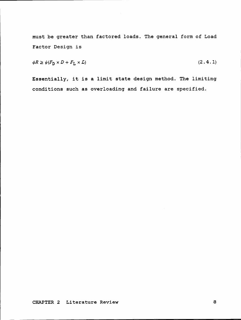
Simplified lane loads of HS20-44 truck (AASHTOl 3.7.7)
are used for the calculation of deflection as shown in Figure
6. Therefore, the deflection can be calculated by
CHAPTER 3 Design of Concrete T-beam Bridge Decks 14
I
I
I8 I<ip5 for momentand deflectionI6 kips for snear
x .....,4O.64I<ip5/ ft
!!!lß!l|M!!l!!!!!l!|!llllllllllhllßßllll|||||||||||||||||||||||
Figure 6. Simplified HSZO-44 Truck Lowd(AASHTO1 3.7.7)
18kips x S3 5 x O. 64kips/foot x S4ÖL="li""*"‘*'*+48EbIe 384EcIe
§-5 Design Qrocedgnes
The design of T-beams is accomplished in the following
steps.
1. Determine the minimum slab thickness by
cs (1¤c1¤)=x12 ‘ (3.5.1)
or 6.5 inches rounded to next larger integer (AASHTOl
8.9.2)
lCHAPTER 3 Design of Concrete T-beam Bridge Decks 15

-r-——'*———'*———————————-———————————**”*——————————"'rrr”rrrrrrrrrrrrrrrrrrri
f2. Calculate moments per foot of slab width. According to E
AASHTOl (3.24.3.1), a continuity factor of O.8 is appli-
cable. Dead load moment is derived from equation (3.5.2).
Live load moment, according to AASHTO1 equation (3-15),
is determined by (3.5.3).
(3.5.2)
ML=0.8xL“‘ä—:'}*-2-El-xwheelload (3.5.3)
3. Check whether the minimum slab thickness fulfills the
flexure strength requirement.
4. Determine the effective flange width by equations
(3.3.1-3)
5. According to AASHTOI (8.9.2), let effective beam depth
equals to éiäg- rounded to next larger inch integer.
Assume appropriate web width of beam.
6. Calculate dead load by
a. Adding 25lb/footz future wearing surface on the top.
b. If two layers of bars are used, add 3.9 inches to d
as height of girder, as shown in Figure 7-a.
c. If three layers of bars are used, add 5.1 inches to
d as height of girder, as shown in Figure 7-b.
d. If four layers of bars are used, add 6.4 inches to d
as height of girder, as shown in Figure 7-c.
CHAPTER 3 Design of Concrete T—beam Bridge Decks 16

l
ÄIÄZÄIÄZÄIÖ. *5 stlrrupsÄIIIÄIIZÄIÄ: *8 behdlhg
d -Q-j-Q-j-jq relhforcemehts_ h *Ä·I·I·I·Ä·I Centrolo Of Steel Bars
·
_ l.S°° cover + O.63°‘ stlrrups° ‘
-
+ l bar olameter6a + .7S" ohe half clear soacihg
= 39" = h — d
#5 stlrrwosÄ·I·Ä·Ä·Ä·Ä· *8 behdlhg
d I;I;I;I;I;I; relhforcemehtsh Igigijigigl; Cehtroio Of Steel Bars“ “:?:?:¢:“ ‘¤
A A*A·A A Ä ·
äl.5°‘ cover + O.63" stlrrups
‘ + l .'°><l.S bar dlameters6b + l S" clear spaclhg
= S. l" = h · d
·I^I·I·I·I·I·I; Ijijljjljij °·° °^‘·°~°^,”„^°„, *5 stlrrupsI ·I·I·I·I·I·I #8 bendlllg
d Q ·j~§·§·j·~‘;·§ relhforcementsh I ·‘·I;I;I;Z·
ECentrold Of Steel Bars
^ ‘ a l.S" co_ver + O.63'° stlrrupsE^1·j·§·j·^ + l .“><2 bar dlameters
+ l .S°‘><l.S clear spaclngs6c = 6.4 = rl - 6
Figure 7. Determination of Girder Height
CHAPTER 3 Design of Concrete T-beam Bridge Decks 17
l

11
7. Calculate dead load moment and shear, and find live load
moment and shear from AASHTOI Appendix A (also listed in
Appendix A of this thesis).
8. Calculate the impact factor from
1:%% (3.5.4)but I;;0.3 according to AASHT01 (3.8.2.1).
9. Calculate required. moment and shear resistances from
equation (3.1.1)
10. Check that shear resistance of concrete is greater than
20% of the minimal shear strength required as discussed
in section 3-3; otherwise, the cross-sectional area must
be increased (go back to step 5).
11. Examine the dimension provided is a T-beam design or a
rectangular beam design by assuming the depth of equiv-
alent rectangular stress block equals to the slab thick-
ness of the beam. That is, if equation (3.5.5) is
satisfied, it is a rectangular beam design; otherwise,
it is a T-beam design.
> fg- (3.5.5)
12. If it is a rectangular beam design, use equation (3.5.6)
to determine a . If it is a T-beam design, use equation
(3.5.7) instead.
CHAPTER 3 Design of Concrete T-beam Bridge Decks 18

(3 5 6)
0 85fc' 1*5- 1 - Mu. (tS(bE—bw)(d— )+abw(d— ))-——— (3.5.7)2 2 24>
13. Use either equation (3.5.8) for rectangular beam design
or (3.5.9) for T-beam design to calculate required steel
area.
AsfY=O.85fc’abE (3.5.8)
AS£y=O.85£c'(tS><(bE—b„,)+abw) (3.5.9)
14. Check the web width by arranging reinforcements. If it
is not satisfied, go back to step 5.
15. According to AASHTOI (8.16.3.3.3), check that the steel
area fulfills the maximum and the minimum steel area re-
quirement by
0.85:. -b I2Asf- (3.5.10)Y
Asfpf:-—— (3.5.11)
bw :6 87000pb-( IDE )[O.85ßlx {Y x( 87000+):,}, )+pf] (3.5.12)
max.AS=O.75xpbxAC (3.5.13)
CHAPTER 3 Design of Concrete T-beam Bridge Decks 19
According to AASHT01 (8.17), the minimum steel area re-
quired is that Mh provided by the minimum AS should be
able to resist 1.2><Mcr where cracking moment is calcu-
lated by
f}><IgM = ···——·———· 3 . 5 . 14
QfIf the maximum or the udnimum AS requirements is not
fulfilled, cross section must be changed (go back to step
5).
16. Check that the deflection fulfills the requirement,
6LS jgägl (AASHTOI 10.6.2), as discussed in section 3-4;
otherwise, cross-sectional area must be increased (go
back to step 5).
3-6 Design Example
By following the design procedures discussed in the pre-
vious section, an example illustrating the design of a T-beam
bridge is presented in this section. The span of this example
is 40 feet.
1. Assume the web width of T-beams is 12 inches; thus, thebeffective span is 6 feet — ä >< TEL = 5 . 5 feet .Fromequation
(3.5.1),
CHAPTER 3 Design of Concrete T-beam Bridge Decks 20
I
III
—§-3%;-Q·=0.517foot<0.542foot (3.5.1)
Rounded to next larger inch integer, the minimum slab
thickness is 7 inches.
2 . The density of reinforced concrete is 0. 15 kipsw/foot3,
therefore the distributed dead load per foot width be-
comes
ts _WD=0.15 x-3.;-+-0.025=0.113 kips/foot/foot (3.6.1)
While continuous span is considered in the transverse
direction, a continuity factor of 0.8 (AASHTOl 3.24.3.1)
can be applied to calculation of moments, which results
in
MD=O.8><—äxWD><s2=0.340foot—kips/foot (3.5.2)
(S + 2) . .ML=0.8><——-5T-x 16k1ps=3.00foot—k1ps/foot (3.5.3)
From equation (3.5.4), the impact factor
I =——é-Q———= 0.384. Therefore, the value of I is 0.3 ac-125 + scording to AASHTOI (3.8.2.1). From equation (3.1.1), the
per foot ultimate moment is
Mu = 1.3 x (MD + 1.67 x (1 + I) ><ML) = 8.91 foot —-kips/foot
(3.1.1)CHAPTER3 Design of Concrete T-beam Bridge Decks 21

(3. Use specified concrete strength fc'= 4,000 psi, yield
strength of reinforcements fy = 60,000 psi, and ratio of
depth of rectangular stress block ßl==0.85 (AASHTOI
8.16.2.7), the balanced steel ratio can be calculated by
equation (3.6.2) according to AASHTOI (8.16.3.2.2).
(3.6.2)
The maximum allowable steel ratio is 75 percent of the
balanced steel ratio specified by AASHTOI (8.16.3.1.1),
that is, pmax==0.02l4. The effective slab depth is equal
to the slab thickness minus 2 inch cover for top re-
inforcements (AASHTOl 8.22.1) and one half the re-
inforcement diameter (no.6 bar with 0.75 inch diameter).
Thus, effective slab depth is 4.62 inches. The depth of
equivalent rectangular stress block of concrete can be
solved by equating compression of concrete and tension
of reinforcements as
0.85fc'ab=ASfy (3.6.3)
Rearrange the equation (3.6.3) and substitute the magni-
tudes of variables, resulting in ¢;—= 0.7353 AS. Next,
by equating the required moment resistance to provided
moment resistance as given by
CHAPTER 3 Design of Concrete T—beam Bridge Decks 22
(.

°Mu
x 12 a (3.6.4)
required tension steel area can be determined by solving
44.12A§—277.2AS+1l8.8=0 (3.6.5)
As As = 0. 463inch2/foot is determined, steel ratio thusAequals to ü = 0.0083, and is less than pmax. In order
to check minimum AS requirement, several calculations
must be made first.
fr=7.5x./fc' =474psi (3.6.6)
(3.6.7)
ytop=-é'-x7=3.5inches (3.6.8)
The cracking moment, Mcx., is checked by ’
fx. x Ig U Mu3.87foot —k1ps/foot (3.6.9)
Therefore, the minimum steel area requirement is sati s-
fied. That is, ts = 7.0inches is adequate.
4. From equations (3.3.1-3) and span of 40 feet,
CHAPTER 3 Design of Concrete T-beam Bridge Decks 23

—ä—xSx12=120.iz2ches (3.3.1)
6x l2=72 inches (3.3.2)
12 x7=84 inches (3.3.3)
the effective flange width is 72 inches, which is domi-
nated by eguation (3.3.2).
5. Let d = 34inches and bw = 12.inches.
6. The distributed weight of future wearing surface is
25lb/footz x 12 feet = 0. 30 kips/foot . Use two layers of
bars and let beam height equals to 38 inches. Therefore,
the distributed dead load can be calculated by
W121:5 2(h—7)bw 015 03 213k' f t 3610D-[12+ 144 ]. +.-. 1p/oo (..)
7. Calculate the dead load moment and shear from
MD=-äxWDxS2=425.0foot—kips/lane (3.6.11)
VD=WDxSx%=42.5kips/lane (3.6.12)
From Appendix A, find live load moment and shear corre-
sponding to a span of 40 feet. These values are
ML = 449 . 8 foot - kips/lazze and VL = 55 .2 kips/lane.
F
CHAPTER 3 Design of Concrete T-beam Bridge Decks 24
( _ 1

8. For a span of 40 feet, the impact effect calculated from
equation (3 .5.4) is 0.303 . Since this value is larger
than 0.3, I = 0.3 is used instead, according to AASHTOI
(3 . 8 . 2 . 1).
9. From equation (3.1.1), calculate the moment and shear due
to factored loads by using
Mu = 1.3(MD + 1. 67 x (1 + I) ML) = 1822 foot — kips/lane (3 . 6. 13)
VC= 1.3(VD + 1.67 x (1 + I) VL) = 21l.0kips/lane (3.6.14)
Nominal moment strength and shear strength are calculated
by dividing strength reduction factors using
MMn =—-L-‘L=~%gé;= 2024 foot — kips/lane (3.6.15)
Vu 211.0 .Vn-T- 0.85 -248.3k1ps/lane (3.6.16)
10. The nominal shear force carried by concrete is calcu-
lated from
VC = 2 x 2 ./fc' bw d = 103 .2 kips/lane (3 . 6. 17)
The VC must be larger than 20% of the shear force applied
on the member; otherwise, an increase in the cross-
sectional dimensions of the member is required. This
CHAPTER 3 Design of Concrete T-beam Bridge Decks 25

point is checked by equation (3.6.18). The fraction left
of the shear force can be designed to be taken by shear
reinforcements.
O.2V¤=49.7kips<103.2kips OK! (3.6.18)
11. Use (3.5.5) to check if it is a T—beam design or a rec-
tangular beam design.
ts .O.85fc’tSbE(d-—E—)=4355.4foot—k1ps (3.5.5)
It is greater than the design moment of each T—beam sec-M
tion, iää ; thus, it is a rectangular beam design.
12. Use equation (3.5.6) to determine the location of the
depth of equivalent rectangular stress block.
a Mn (0.85£c’abg(d-E—)=—E-(for each beam) (3.5.6)
Therefore, a = 1.49 inches (3.6.19)
13. From equation (3.5.8), the steel area is determined to
be 6.O9inch2.
ASfy=O.85><fc'xaxbE (3.5.8)
CHAPTER 3 Design of Concrete T-beam Bridge Decks 26

14. Use two layer of #8 steel bars, 4 bars each layer,
AS = 6.28inch4 , the spacing between bars is one inch and
. 75 inch as diameter of shear reinforcements, the re-
quired web width is 11.5inches and is less than 12inches.
15. Check the maximum and the minimum steel ratios by
_ (3.5.lO)
pf=0.0583 (3.5.].1)
pb=O.Ü].45 (3.5.].2)
max. As = O . 75pbAc = 9 . 52iz1c:h4 2 6 . 28iz2ch4 (3 . 5 . 13)
The concrete fracture modulus is 474psi from (3 . 6. 6) .
The location of the centroid of concrete cross section
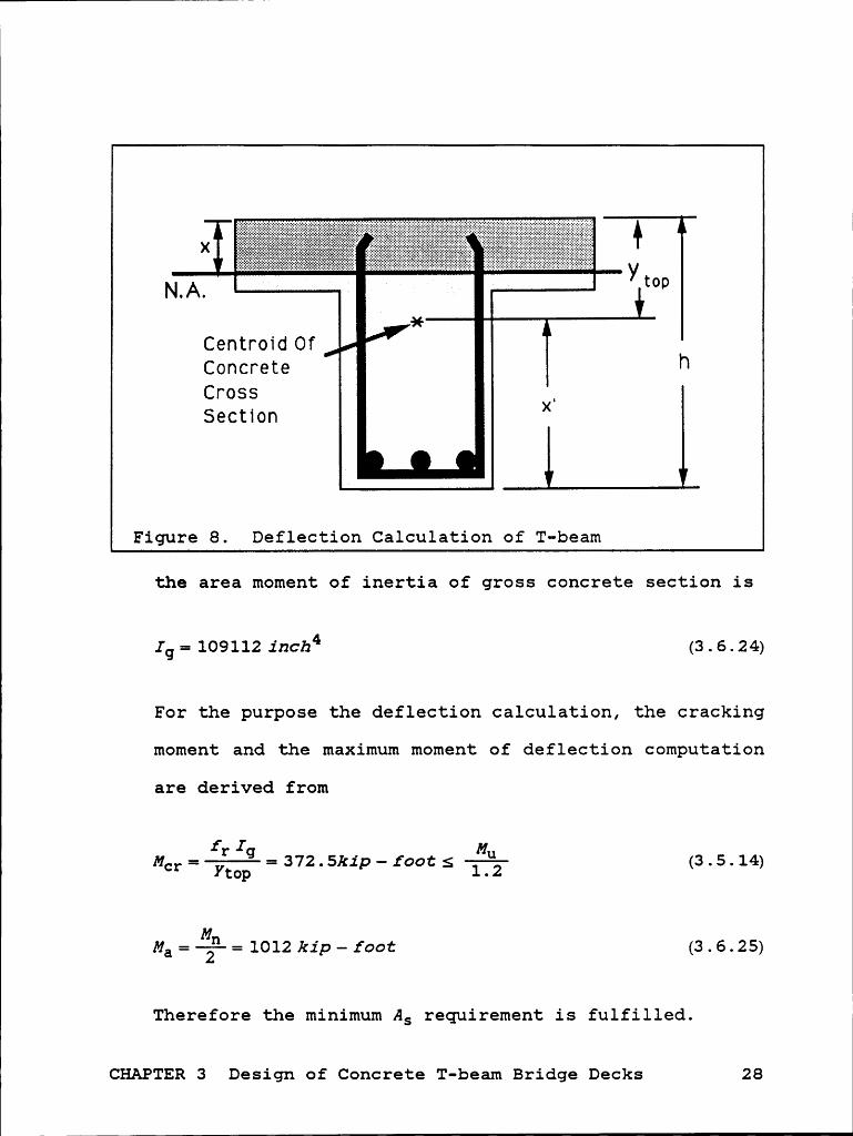
is derived as shown in Figure 8, from
h ts _ - 3 (3.6.20)
AC = 876 .iz2ch2(concrete area) (3 . 6.21)
(3.6.22)c
ytop=h—26.43=11.57 inches (3.6.23)
CHAPTER 3 Design of Concrete T-beam Bridge Decks 27
1
><,..................... ...............,.....................C
e n t ro 1 d 0 fConcrete hCross X,S e ct 1 o n
Figure 8. Deflection Calculation of T-beam
the area moment of inertia of gross concrete section is
Ig= 109112 111::114 (3.6.24)
For the purpose the deflection calculation, the cracking
moment and the maximum moment of deflection computation
are derived from
M ='{E'*li=372.5kIp—fOOCSÄ (3.5.14)cr Y1;gp 1 . 2
Mn·Ma=T= 1012 k1p—foot (3.6.25)
Therefore the minimum As requirement is fulfilled.
CHAPTER 3 Design of Concrete T-beam Bridge Decks 28

16. Calculate deflection by determining the location of the
neutral axis from equations (3.6.26) to (3.6.28) first.
The cracking area. moment of inertia is derived from
equation (3.6.29).
ASxnx(d—x)=bExxx—‘:2L (3.6.26)
36xZ-+50.27x-l709==0 (3.6.27)
x==6.23inches (3.6.28)
I _And 2 _L 3_ . 4cx.- S( -x) + 3 bEx -445661nch (3.6.29)
The effective area moment of inertia is determined from
I =(—l!g—!;-)3I +[l—(h)3]I =47785inch4gI (3 4 1)8 Ma Q Ma cr Q ° '
Therefore, Ie==47785, the deflection is
_ _ spanqf-0.2281nch< —§66— (3.6.30)
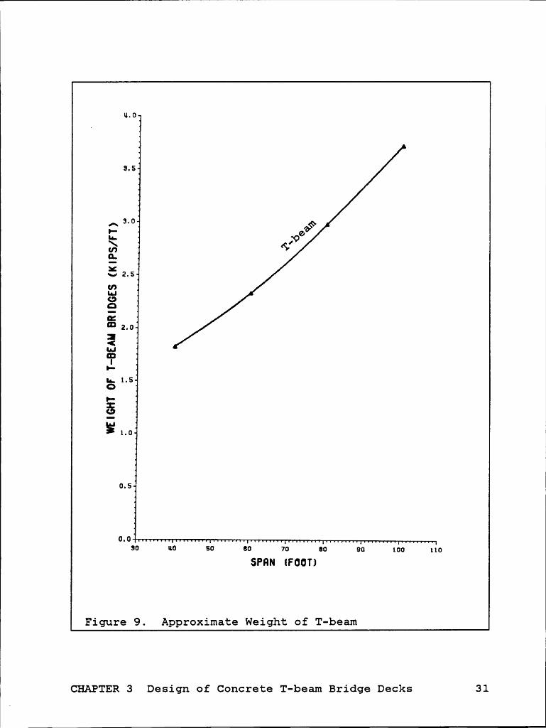
The design results of spans from 40 feet to 100 feet are
listed in Table 1, and the weight curve is shown in Figure
9. By looking at the nominal moments of the T-beams in Table
CHAPTER 3 Design of Concrete T-beam Bridge Decks 29
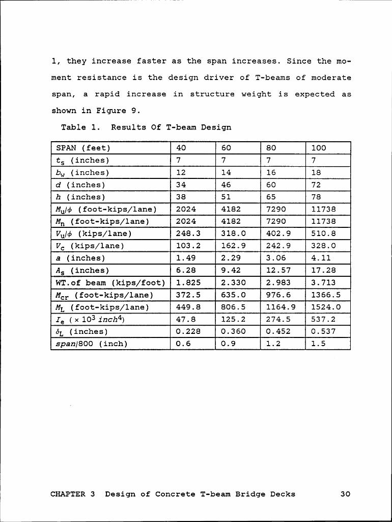
1, they increase faster as the span increases. Since the mo-
ment resistance is the design driver of T-beams of moderate
span, a rapid increase in structure weight is expected as
shown in Figure 9.
Table 1. Results Of T-beam Design
SPAN <2222> 122ts (inches) 7 7 7 7bw (inches) 12 14 16 182 (inches) 34 li 72h (inches) 38 51 65 78ßqg¢ (foot-kips/lane) 2024 4182 7290 11738Mh (foot-kips/lane) 2024 4182 7290 11738Kj¢ (kips/lane) 248.3 318.0 402.9 510.8VC (kips/lane) 103.2 162.9 242.9 328.0a (inches) 1.49 2.29 3.06 4.11AS (inches) 6.28 9.42 12.57 17.28WT.of beam (kips/foot) 1.825 2.330 2.983 3.713MCr (foot-kips/lane) 372.5 635.0 976.6 1366.5ML (foot-kips/lane) 449.8 806.5 1164.9 1524.0ze (X 1031116114) 47.8 125.2 274.5 537.2ÖL (inches) 0.228 0.360 0.452 0.53722227222 <1¤<=¤> li 1-2 1-2
CHAPTER 3 Design of Concrete T-beam Bridge Decks 30
11.0
3.5
3.0
{ 29U')E-
2.5thIn-I0EIZ‘¤ 2.02<1.11‘P•·—In 1.50
E1.0
0.5
0.0so 110 50 80 70 ao 90 100 11 0
SPHN (FUUT]
Figure 9. Approximate Weight of T-beam
CHAPTER 3 Design of Concrete T-beam Bridge Decks 31

T K
CHAPTER 4 STEEL·CONCRETE COMPOSITE SECTIO§
The strength of a steel-concrete composite section de-
pends on the mechanical interaction between the steel beam
and the concrete slab. The steel beam is securely bonded to
the concrete slab by carefully designed shear connectors so
that the steel beam and the concrete slab act together as a
T-beam. A typical cross section is shown in Figure 10.
CONCRETE SLAB
SHEAR CONNECTORS
STEEL BEAM
COVER PLATE
Figure 10. Typical Cross Section of Steel-Concrete Com-posite Section
There are two basic construction methods for steel-
concrete composite section and their design procedures are
different.
CHAPTER 4 Steel-Concrete Composite Section 32
l
1. Shored construction: Temporary· shores are used, during
construction. The concrete slab is supported by
shores until the concrete attains 75% of its spec-
ified final strength.
2. Unshored construction: Temporary shores are not used
during construction. The concrete slab is supported
by the steel beam.
The purpose of the following design is to derive an ap-
proximate weight curve of a composite beam with spans from
40 feet to 100 feet. Shored construction is assumed. Cover
plates shown in Figure 10 are not used. Design of shear con-
nectors is ignored. Steel beams considered will be standard
rolled W-shapes (AISC3). Lateral support of the beams may be
necessary for some of the cases, but the design of this por-
tion is omitted and the weight of lateral supports is not
included in the final total weight of the structure. The
cross section considered is shown in Figure 11.
CHAPTER 4 Steel-Concrete Composite Section 33
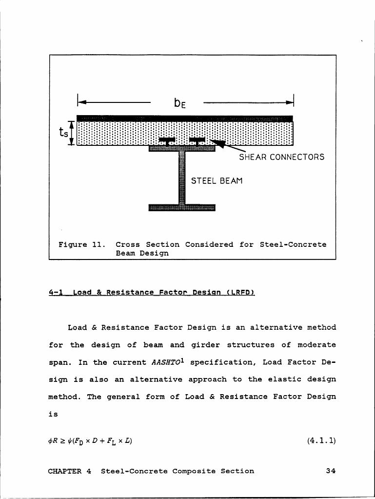
|‘**T—t' D5 ———l·——·—>|
SHEAR CONNECTORS
STEEL SEAM
Figure ll. Cross Section Considered for Steel-ConcreteBeam Design
9-; goad g gesistance Factor Desigg QLRFD}
Load & Resistance Factor Design is an alternative method
for the design of beam and girder structures of moderate
span. In the current AASHTO1 specification, Load Factor De-
sign is also an alternative approach to the elastic design
method. The general form of Load & Resistance Factor Design
is
¢Rz¢GbxD+FLxm (4J.D
CHAPTER 4 Steel-Concrete Composite Section 34

IAccording to AASHTOl specification, strength reduction
factor considered is 0.9 for moment and 0.85 for shear.
Analysis factor is 1.3. Dead load factor is 1.0. Live load
factor is 1.67. Live load should include appropriate impact
effect up to 30% of the live load. Load & Resistance Factor
Design equation in the design of steel-concrete composite
sections, therefore, has the form of
¢>R21.3[1.0><D+1.67><(L+I)] (4.1.2)
4-g Tgickness of cogcvete Slag
The requirements for the minimum slab thickness of
steel-concrete composite beams are similar to those of rein-
forced concrete T-beam design. The principal difference is
that the web width of T-beam shall be replaced by flange
width of the steel beams.
In the design approaches here, the steel-concrete com-
posite section will has the minimum slab thickness required
in the transverse direction.
9-; Qimegsiog gf y—sgc;iog
Three factors are considered in the selection of steel
beams. These are moment, shear, and deflection requirements.
CHAPTER 4 Steel-Concrete Composite Section 35

N
Because the steel beam and the concrete slab are taken as a
unit, the combined strength and stiffness should be higher
than these requirements.
Referring to AISC3, partial design of steel-concrete
composite sections will be completed and the corresponding
weight evaluated.
4-4 Deflection
According to AASHTOl (10.6.2), deflection induced by live
loads must not exceed 1/800 of the bridge deck span. For fc'E
= 4000 psi, modular ratio of elasticity, 7äL, equals 8, byc
converting concrete slab area into equivalent steel cross
sectional area as shown in Figure 12, the area moment of in-
ertia can be determined. With the simplified live load spec-
ified by AASHTOl (3.7.7), the deflection induced by live load
is calculated by elastic formulas.
CHAPTER 4 Steel-Concrete Composite Section 36

I
I
>|.. ......E U U I V 6 I 6 VI I 5 I 6 6
I:. .1. :„·.·„·. .7.-z.-.7._.g„g._.·.•
ä
Steel beam g%
Figure 12. Equivalent Steel Cross Section
Q-§ Desigg Egocgdggeg
As discussed in sections 4-1 to 4-4, the design of
steel-concrete composite sections is accomplished in the
following steps.
1. Similar to the first three steps in section 3-5, deter-
mine the minimum slab thickness requirement in transverse
direction.
2. Assume appropriate steel beam weight in the longitudinal
direction.
3. Calculate dead load from
CHAPTER 4 Steel-Concrete Composite Section 37

t (4.5.1)
4. Calculate dead load, moment and shear from equations
(4.5.2) and (4.5.3), get live load moment and shear from
Appendix A, then determine the required load resistances
from equation (4.1.1).
M ——l w sz 4 5 2D- 8X DX (• •)
D= D><S><? (4.5.3)V w 1
5. Determine effective concrete flange width from equation
(3.3.1-3).
6. Assume depth of equivalent rectangular stress block and
depth of steel beam.
7. Using properties of F36 steel, calculate estimated weight
of steel beams from equation (4.5.4) [AISC3 (LRFD pp 4-10
c)].
Mu><12 (4.5.4)(?'+YcQ¤"?)¢FY
and check it with the assumed steel beam weight. If large
difference is found, go back to step 2.
8. According to WT derived, try appropriate W-sections.
CHAPTER 4 Steel-Concrete Composite Section 38
)\ __ ,

9. Find the maximum Zgn where plastic neutral axis located
at the top of steel beam.
10. Calculate required a from equation (4.5.5) (AISC3 4-10
c), and compare with the value assumed in step 6.
4 5 5a° 0.85fc'bE (‘ ‘)
If large difference is found, go back to step 6.
ll. As shown in Figure 13, determine YZ from
(4.5.6)
12. Find factored nominal moment strength,«¢Mh, of the cor-
responding YZ from AISC3 (c.4) and check with
(4.5.7)
If it is not satisfied or the design is too conservative,
go back to step 8 and select another W-section.
13. Check shear load resistance by
¢xO.6xFyxAw2Vu (4.5.8)
If it is not satisfied, go back to step 8 and select an-
other W-section.
14. Check deflection induced by live load and impact as dis-
cussed in section 4-4. If the deflection requirement is
} CHAPTER 4 Steel—Concrete Composite Section 39

II
-1----—-——— DE
v3COD
Concrete SlabSteel beam
Figure 13. Illustration of Steel-Concrete CompositeBeam Design
not satisfied, either go back to step 1 for thicker con-
crete slab or go back to step 8 for another W-section.
4-6 Design Examgle
By following the design procedures discussed in the pre-
vious section, an example illustrating the design of steel-
concrete composite beams is performed in this section. The
span of this example is taken as 40 feet.
CHAPTER 4 Steel-Concrete Composite Section 40
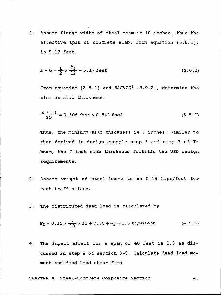
1. Assume flange width of steel beam is 10 inches, thus the
effective span of concrete slab, from equation (4.6.1),
is 5.17 feet.
.s=6-lxiä-=5.17feet (4.6.1)2 12
From equation (3.5.1) and AASHTOI (8.9.2), determine the
minimum slab thickness.
=O.506foot<O.542foot (3.5.1)Thus, the minimum slab thickness is 7 inches. Similar to
that derived in design example step 2 and step 3 of T-
beam, the 7 inch slab thickness fulfills the USD design
requirements.
2. Assume weight of steel beams to be 0.15 kips/foot for
each traffic lane.
3. The distributed dead load is calculated by
(4.5.1)
4. The impact effect for a span of 40 feet is 0.3 as dis-
cussed in step 8 of section 3-5. Calculate dead load mo-
ment and dead load shear from
t
CHAPTER 4 Steel-Concrete Composite Section 41

MD=—é-xWD xS2=300 foot—kips/lane (4.5.2)
VD=WDxSx%-=30 kips/lane (4.5.3)
From Appendix A, live load moment and shear are
ML = 449 . 8 foot - kips/lane (4. 6 .2)
VL = 55 .2 kips/lazze (4. 6. 3)
From equation (4.1.1), the factored moment and factored
shear are calculated from
Mu= 1.3 [300 + 1.67 x 1.3 x 449.8] = l660foot — kip/lane (4.6.4)
Vu = 1.3 x [30 + 1.67 x 1.3 x 55.2] = 194.8 /zips/lazze (4.6.5)
5. From equations (3.3.1-3), effective flange width is de-
termined.
120 mcbes (3.3.1)
6 x 12 = 72 inches (3.3.2)
12 x7=84 izzches (3.3.3)
bE = 72 inches (4. 6. 6)
CHAPTER 4 Steel-Concrete Composite Section 42

. 1
6. Assume depth of equivalent rectangular stress block is 3
inches and depth of steel beam is 24 inches.
7. From equation (4.5.4), calculate approximate weight of
steel beams.6
1695.5/2 x 12
8. Try W24><68 steel beams, bf==9inches is very close to the
value assumed in step 1.
WS = 0. 136 kips/foot < 0. 15 kips/foot (4. 6. 7)
9. From AISC3 4-20, nominal shear strength of shear connec-
tors is 724 kips.
10. Required a is determined by
_ 724 _ . ~ . (4.5.5)
and the value derived is very close to the assumed value;
therefore, no correction is needed.
11. From equation (4.5.6), YZ is determined.
YZ=7——;—=5.5i11ches (4.5.6)
CHAPTER 4 Steel-Concrete Composite Section 43

11
12. From AISC3 4-20, ¢> Mn equals 890 foot-kips, which is
greater than and is very close to one half of the moment
due to factored loads for each traffic lane.
13. From equation (4.5.8), the shear strength of the steel
beams is proved to be satisfactory.
. Vu¢>V¤=0.85x0.6xFyxAw=181k1ps>T (4.5.8)
14. As shown in Figure 12, the transformed steel block is a
square of 9inch><7inch. Cross sectional area of a steel
beam is 20.1inch2. Thus the equivalent area moment of
inertia is calculated to be 5689 inch4. By substituting
the steel elastic modulus equals to 29><106psi, the de-
flection is calculated from equation (4.6.8) and is less40feet _ -than 800 -0.61nch.
18kips x sa 5 x 0. 64kips/foot x S4 _ÖL-+—Ü.241I2Ch (4.6.8)
Same procedures are applied to the cases of different
spans and the results are discussed next.
CHAPTER 4 Steel-Concrete Composite Section 44

I
I
4-7 weight of Structure
The design results of spans from 40 feet to 100 feet are
listed in Table 2, and the weight curve is shown in Figure
14. By looking at the nominal moments of the steel-concrete
composite beams in Table 2, they increase faster but not as
fast as T-beams as the span increases. Since the concrete
slab thickness remains the same and most of the weight comes
from concrete, a slower increase in structure weight, com-
pared to T-beam, is expected.
Table 2. Results Of Steel-Concrete Composite Beam De-sign
SP¤¤bE(inches) 72 72 72 72
ts (inches) 7 7 7 7W-section W24 x68 W30 x10= W36 x15• W36 x232Wt.of beams(kips/foot) 1.186 1.266 1.350 1.514Mh (foot-kips/lane) 1660 3142 4862 6888¢Mn (foot-kips/lane) 1780 3096 4880 7628Va (kips/lane) 194.8 228.9 257.6 287.0¢Vh (kips/lane) 362.0 597.0 822.9 1186.0Aw(inchZ) 9.85 16.26 22.41 32.291g(inchWlane) 11378 23616 41936 65998ÖL (inch) 0.240 0.477 0.758 1.091S¤·=¤/8¤¤ <i¤¤¤> liM M
CHAPTER 4 Steel-Concrete Composite Section 45

i1
u.0
3.5
3.0 p\U')iE5:3 2.5GE?ZCDLUE 2.0ZQ§I-|gg 1.5 'HJI-
u.GF; 1.0S!
0.5
0.080 UO 50 80 70 80 90 ’ 100 110
SPRN IFUOTJ
Figure 14. Weight Curve of Stee1·Concrete CompositeBeams
CHAPTER 4 Steel-Concrete Composite Beam 46

1CHAPIEg 5 COMPOSITE MATEgIAL BRIDGE DEC;
The specific moduli (stiffness/weight) and the specific
strength (strength/weight) of composite materials are higher
than those of concrete and steel. A considerable amount of
weight saving is expected. As an example of design, the con-
figuration of composite material bridge deck is shown in
Figure 15, simply supported in the longitudinal direction,
uniform thickness girder spacing (center to center) of 6
feet, continuous I—shaped floor beams simply supported by the
girders. Bolt connections between girders and floor beams are
suggested but not actually designed. No reduction on the
load resistance caused by holes is considered.
5-l Elastic Desigg
Unlike structural steel, fiber reinforced composite ma-
terials do not have sufficient ductility to undergo plastic
deformation prior to failure. Therefore, design methods in-
volving plastic concepts are not appropriate. Since there is
no specific method for composite material bridge design,
Elastic Design seems to be the best choice. Maximum strength
criterion is widely used in composite design and is adopted
CHAPTER 5 Composite Material Bridge Deck 47

II
1::.::: ::21.. _. .. Q. 1 . _ . ._.:..:Z..Z:;v.:, >.;.ti:;;‘_. _ gf ":;7/ aav -. J’r *‘ th I C knsss I O O
Wear 1 ng Surfac 1 Fd' ‘
5 I b/ I°°I « Np
viv.....,q.
. i..................... 2’6fe etInterior Traffic Lane
Ä%I
40 to l00 feet Simply Supported
|«— 48 ··ZFEÜ?ÄZÖZÄZÄTÄQ}?§?Äi;?ħ:§;§:?Ü?CCJZ}Ü'!i?:Ü¥:?Ö?t—'*·;}:?:§;;:?:{'?‘? Z · :ZEZ.gig:_-_·_§pääg:Zé§:§:§:ZEZ:ZEZEZ:¢rZi}:§§§Z:§:—:Z.*Y··· :~„~=:¢r¢.¢*:¢2Z:¢:¢:E:gg}i§:Z:Z:¢:¢r¢:·:¢ä·€¢?¢:i:E:i§§§gi§;; äääiééääiäfäS5äiifäiiiiiiää§E€€€EfE€E€E€???f€?E$€?E?EZ€ÜE2EÜEZEZEZQEZEZEZ€Z¢$€Z?EE}‘Y?Z€Z?Z‘?€Z€Z€Z€Z€Z?Z‘‘
2;. .. . ; y_____ V; ;;;.....,. E; .
Floor Beam Cross Section
Figure 15. Composite Material Bridge Deck
CHAPTER 5 Composite Material Bridge Deck 48

I
I
for this thesis. The load and resistance are related by con-
sidering safety factor equals to 1.67, which results
R2l.67><(D+L(1+I)) (5.1.1)
5-g Mategial ggogerties
All the composite materials considered are continuous
fiber reinforced resins. Properties of unidirectional com-
posite materials are listed in Table 3.
Table 3. Composite Material Properties
El E2 Xt Xt DensityYt Yc Shear
(msi) (msi) (ksi) (ksi) (ksi) lb/ft3T300/5208 217.5 217.5Graphite/Epoxy 26.25 1.49 5.8 35.7 9.86 99.7B(4)/5505 182.7 362.6Boron/Epoxy 29.59 2.68 8.9 29.3 9.72 124.6AS 4/3501 209.9 209.9Graphite/Epoxy 20.01 1.3 7.5 29.9 13.49 99.7Scotchply 1002 154.0 88.5Glass/Epoxy 5.6 1.2 4.5 17.1 10.44 112.1Kevlar 49 203.0 34.1Kevlar/Epoxy 11.02 1.7 7.7 4.93 90.96
For bridge deck structures, strength and stiffness re-
quirements differ significantly in different directions.
This characteristic matches one of the advantages of compos-
ite materials, which is the mechanical properties of the
CHAPTER 5 Composite Material Bridge Deck 49

L
Lcomposite materials can be designed as a function of orien-
tation. Therefore, a member with most of the fibers oriented
parallel to the direction in which the largest strength and
stiffness are required should be used.
5-3 Qeflectiog —
The same deflection requirement as that of concrete T-beam
and steel—concrete composite section is applied to the design
of composite material bridge deck. Calculation of deflection
is based on elastic formulas.
5-9 Eloon Beam Desigg
The cross section of the floor beam is considered as shown
in Figure 16. Each floor beam will be connected side by side
to form a continuous slab lying between girders. Appropriate
connection between girder and floor beam, and between floor
beams are assumed.
According to AASHTO1 (3.30), the tire contact area is
considered equal to 0.0lP, where wheel load P is 16 kips.
The width and length ratio is 1/2.5. That is, the tire con-
tact area is considered a rectangular of 8inches><20inches.
Contact pressure is 100 psi. This type of loading as shown
CHAPTER 5 Composite Material Bridge Deck 50

I
48II
I trgg
§%gszzgzz;sse;;2;;;2;;;z;2;s;s2;2;2;z2;2;;s;2;2;~2=&2;s;2;2;2;2;2;s;2;2;2=2;2;2¤2;2;2;2;%;s=2¢6;2:2;2;2¤6;2;Ztw
d "'+
Figure 16. Dimension of Floor Beam
in Figure 17 will be applied on several critical positions
of floor beam and design floor beam by considering moment and
shear on both directions and punch shear resistance.
Since the top flange has to resist loads acting in both
x and y directions as shown in Figure 17, top flange of floor
beam is considered having half of the fibers oriented in each
direction. The laminate strength will be considered as one
half of that of unidirectional laminae in both directions
because the transverse strength of a unidirectional lamina
is very weak compared to the longitudinal strength. In addi-
CHAPTER 5 Composite Material Bridge Deck 51

4444+++ 4+•4•·4444+++ +4 44 4 444444444 4 4 Q4 4 4;••
2Ol! xy,
x.444444444 44*4**
x_.__••·•••*••*•************* ***
’4* ·••4•••·••4•••••••• 44-•44••••4•4••• 4 xxx _,4444444+4444444444444•444 44 44}*444444444 44444444444444 4 •4 _.
4 4 4 4 4 4 4 4 4 4 4 4 4 4 4 4 4 4 4 4 44 -*‘ /4, „ — 4_44 4 4 4 4 4 4 4 4 4 4 4 4 9
vqvyv 44444QQ44444444444444+4¢+¢0+ v•••••••••~ ‘••••••••*•**°** V _: ,,#444444444444444444444444444444444444Q444444444444444444+
44444444•4444•44444444444444
,x.4 4 4 4 4 4 4 4 4 4 4 4 4 4 4 4 4 4 4 4 4 4 4 -* * 5
4 .5444444 4444444444 .-5:-,.4444•4444444444444444•••4444 „r 4444¢444 44*4 44 .-.-.:1.-r44•44+444+44•444•444444444• 44444 44 44 444 44444 4
•"444444444444•44444444+44444444444444444•4444+4444444444444444444•4444444444·4444444444444+444444444444444444•+444444•444•44444444444444•4444444444
4444444:444444444444444444444444444444444444xxx44 -,-,,-*4-·44444444+4444444444444444444444444444444·444444444444444•444444444444 •••••4•4•••4•4••44+4•4 , 1:
·. ·. . .;
1**-:5-. . __
:·:·:~; *-:75:2:2;; 2:2:.;.;.;. Z1'
-C-C
Figure . 1ve Load on Floor Beams° 17 L'
tion, E2 is also much lower than E1. Thus, with the uniform
i ' 90° 1 ' ' h 'StI'8 I1 8SSL1mp'C1OI1, 8 8yGI 111 8 ].8m1!18CG 8S 8 m1I1OI‘
CO11tI°1bL1‘l'.lOI1 to 'ChG l8m1I18'CG S‘CI‘GI1Q’th.
OI° WG 811 O Om 8I1gG, mOS O G l GI W1 GF b d b tt fl t f th f'b ’11 b
COI1SldGI°Gd OI'1GI1‘CG 111 thG 1.I‘GCtlOI1 pGI°pGI1d1CL1].8I‘ to ‘ChG• • • • • • • •
'CI'8ff1C dlI°GCtlOI1. SZLIICG SpGC1f1C St8Ck1I1g SGqI.1GI1CG 1S 11012• • • • •
d I 18 COI1CGI'I1 811d 8 U.111d1I'GCt1OI18l ].8m1I18tG ILS 110t SLIQQGSÜG , G
strength and st1ffness are taken as 85 percent of the prop-
GI‘t1GS of 8 L1I1lÖ.lI‘GC'ClOI18l l8mlI18CG. It should G I10tG t 8'C
CHAPTER 5 Composite Material Bridge Deck 52

transverse strength and stiffness will thus be greater than1
that of the unidirectional laminate.
The following floor beam design procedures are used to
determine the floor beam weight as a function of girder
width. The results, together with girder design, will be
investigated to derive the best design.
Floor Beam Design Procedures :
1. Assume girder width, then determine the clear span of the
floor beams as effective flange width minus girder width.
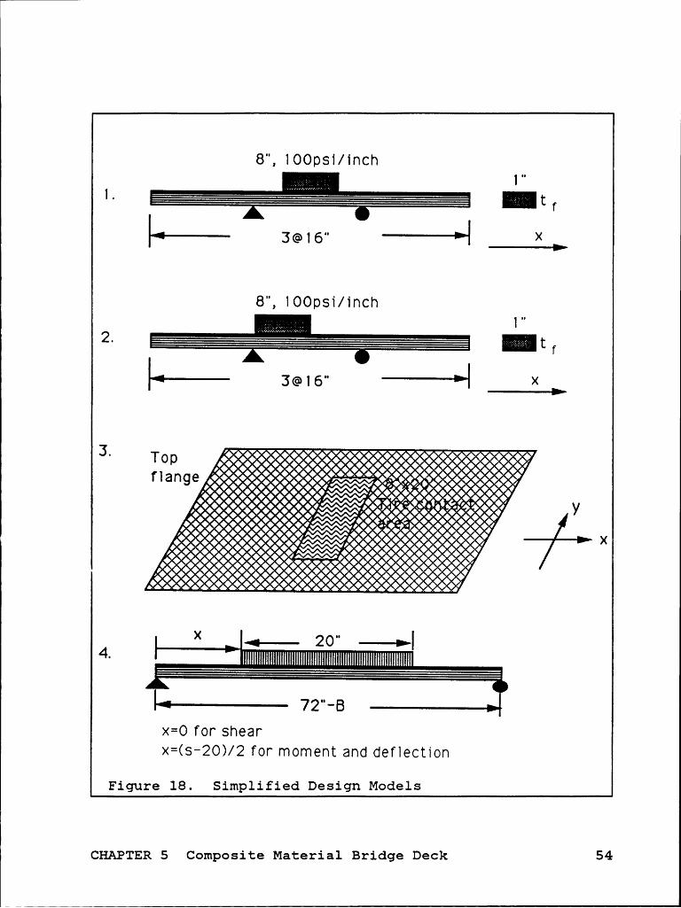
2. According to the simplified design model 1 in Figure 18,
design top flange according to moment resistance re-
quirement.
3. According to simplified design model 2, design top flange
that fulfills shear requirement.
4. Design top flange according to punch shear requirement
and simplified design model 3.
5. From steps 2, 3, and 4, select the maximum value of top
flange thickness.
6. According to simplified design model 4, design the cross
section of floor beam.
7. Calculate the deflection induced by live load based on
simplified design model 4.
CHAPTER 5 Composite Material Bridge Deck 53
1
8", 100061/inchn
If
Li X I
8", 100psi/inchn
""' ' ’I X
.$2%¥$2:tztztztztztztztztztztztzt‘$$1ztztztztxtztztztztztiäf 0a n 960
00000000*0 0 00 0 YX
»000000000000000000000000000000000
X „..... 20** ->|4-
··x
= O f0r she a r><=(s—20>/2 for moment and deflection
Figure 18. Simplified Design Models
CHAPTER 5 Composite Material Bridge Deck 54
1
5-5 Ginden Design
The following girder design procedures are used to de-
termine the girder weight as a function of girder width. The
results, together with floor beam design, will be investi-
gated to derive the best design.
1. For a specific girder width, find floor beam weight along
the traffic direction from the results of floor beam de-
sign in section 5-4.
2. Calculate the weight of future wearing surface in the
traffic direction.
3. Calculate dead load with assumed girder weight.
4. Find the maximum live load moment and shear force corre-
sponding to the span considered from Appendix A.
5. Find required strength of girders from equation (5.1.1)
6. Select material.
7. With the constraint equations (5.5.1-3), determine the
required depth and thickness of girder.
amax = —L!-}L£- 5 flexure strength of material (5 . 5 . 1)x
VQ .Tmax = TT? 5 shear strength of material (5 . 5 . 2)
ömax 5 (due to live load and impact) (5 . 5 . 3)
CHAPTER 5 Composite Material Bridge Deck 55

8. Recalculate the weight of girders and compare with the
value assumed in step 3. If the difference is large, go
back to step 3.
FORTRAN computer program, DECK (listed in Appendix C),
is used to perform these routine procedures. Depth/thickness
and width/thickness ratios are restricted to 60 or less to
avoid possible local buckling of the structure. Buckling
strength of members is not discussed in this effort. The
maximum girder width considered is 30inches.
§-6 Bes; Desigg
Since many variables are involved, structural optimiza-
tion is very complicated. Instead, cases of different condi-
tions are designed. From the results derived, curves will be
plotted in order to find the best design of those considered. °
Besides the strength and stiffness requirements, two more
constraints are added. First, to prevent possible buckling,
-g-andnä} must be less than 60 as discussed in previous sec-tion. Second, to avoid over-deep or over-wide beams, éécnrääare restricted less than 3.
CHAPTER 5 Composite Material Bridge Deck 56

———————·——————————————————*—”*F*—**———‘Y‘55555rtt—————————————————*”————————
5-7 Design Examgle
The case considered in this example is a T300/5208
graphite/epoxy composite bridge deck with a span of 40 feet.
The floor beam is designed first, according to design proce-
dures described.
1. Assume width of girder is 22 inches. Clear span of floor
beam equals to effective flange width minus B, which is
50 inches.
2. According to simplified design model 1, live load moment
is
ML = 2400lb — inch (5 . 7 . 1)
Dead load moment and shear of simplified design model 1
is negligible compared to live load. Therefore,
MR=1.67x(1+0.3)><ML=5210.Zb—inch (5.7.2)
t”¤ *‘ '§‘6 =T-? 5 strength of flange (5.7.3)X tf
.°.Cf= O.536iI2Cb (5.7.4)
,CHAPTER 5 Composite Material Bridge Deck 57

3. Live load shear according to simplified design model 2
is
VL = 600.Zb (5 . 7 . 5)
VR=l.67x(l+O.3)xVL=13O3lb (5.7.6)
Shear stress is determined by
VR X Qz=————— sshear strength of flange (5.7.7)IX X tf
Thus, the flange thickness required is
tf = 0. 583inch (5. 7 .8)
4. Check punch shear requirement according to simplified
design model 3.
5 shear strength of flange (5.7.9)
.’.tf = 0.038iz2ch (5 . 7 . 10)
5. From steps 2, 3, and 4, flange thickness is determined
equal to 0.583 inch.
6. Assume weight of floor beam is 25lb/foot in transverse
direction. Weight of future wearing surface is
25lb/foot: x 4feet = 100.Zb/foot. Thus the distributed dead
CHAPTER 5 Composite Material Bridge Deck 58
1load is 10.4lb/inch. By using simplified design model
4, moment and shear are determined by
ML= 160 kip— inch (5.7.11)
MD=3.3kip-inch (5.7.12)
MR=1.67x((1+l’)><ML+MD)=352.9kip—inch (5.7.13)
VL=12.8kips (5.7.14)
VD=0.26kip (5.7.15)
VR=1.67><((1+I)xVL+VD)=28.2kips (5.7.16)
Shear is considered taken by webs only and ii- ratio isw
taken as 12, thus
VR(5.7.17)
t„=0.345 inch (5.7.18)
d= 4.14 inches (5.7.19)
As shown in Figure 19, location of centroid is 0.933 inch
from the top and area moment of inertia is 44.76 inch4.
Therefore the flexural stress is checked by
MR X _—-—————-=7.35ks1 (5.7.20)Ix
CHAPTER 5 Composite Material Bridge Deck 59
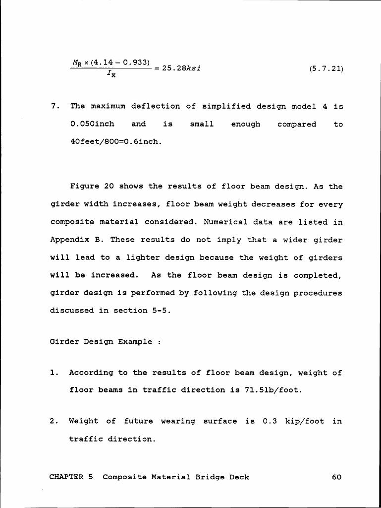
MRx(4.14-0.933) _—————————————————==25.28ksi (5.7.21)Ix
7. The maximum deflection of simplified design model 4 is
0.050inch and is small enough compared to
40feet/800=0.6inch.
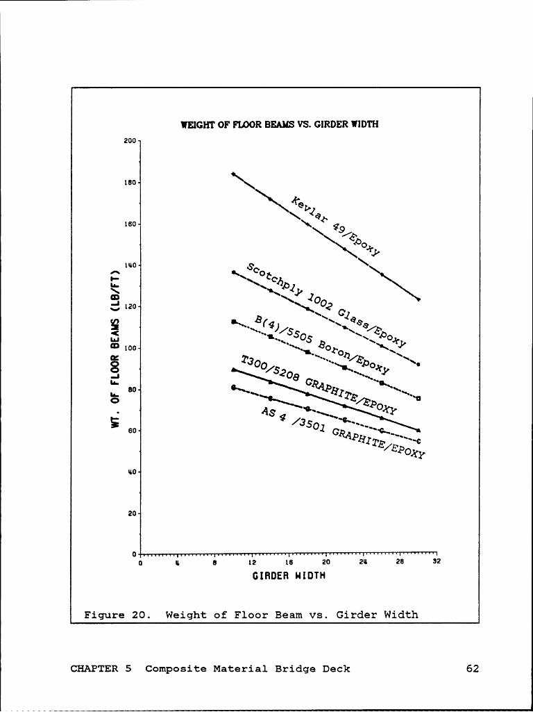
Figure 20 shows the results of floor beam design. As the
girder width increases, floor beam weight decreases for every
composite material considered. Numerical data are listed in
Appendix B. These results do not imply that a wider girder
will lead to a lighter design because the weight of girders
will be increased. As the floor beam design is completed,
girder design is performed by following the design procedures
discussed in section 5-5.
Girder Design Example :
1. According to the results of floor beam design, weight of
floor beams in traffic direction is 71.5lb/foot.
2. Weight of future wearing surface is 0.3 kip/foot in
traffic direction.
CHAPTER 5 Composite Material Bridge Deck 60

1
O. 5 8 3 "I-Z·L·Z·Z·Z·Z-Z-Z-1-1-1-2-Z-I·Z·l·1·i·Z·l·I·Z·I·1·1·1·.·Z·.·l-Z·l·i·L·>l-J·;·l·1·i·L-1-l·.·l·1·I·l·L-L·Z·L·1·L·Z-Z-L·2-;·1-Z-l·L·2-Z·Z·L·2·Z+1-2-1+2-2-‘·'010D·I·Z·2·Z-}?·Z-Z·>?l»>>2-2·l•’:>'·'·‘·Qt Ĥ•t9 3 4. 1 4..
Cb = 3-2O7" Centroid
Figure 19. Design Example of Floor Beam
3. Assume girder weight is 60 lb/foot per traffic lane, the
distributed dead load becomes 0.43kip/foot ( = 0.072 +
0.3+ 0.06 ).
4. From Appendix A, live load moment and shear are
449.8kips-foot and 55.2kips for this case of span equals40 feet.5. Impact factor is 0.3 from equation (3.5.4). Dead loadmoment and shear are derived from
MD=%—xWDx402=86.8foot—kips (5.7.22)
CHAPTER 5 Composite Material Bridge Deck 61
WEIGHT OF FIDOR BEAMS VS. GIRDER WIDTHzoo
160 \
160 \\ ab Q
P1110 so \
^ K\ Qt
Jo;·', 120 O3 C‘ J
ä ‘—¤.____ 505 B ~\ bog100 *~•.,‘
gib!}‘•\\
°= Ta /2 ~11* 8 o °"··Il-1:-
PO6¤ 501 GRPO
ao
zo
0 o u 6 I2 16 zo zu za szGIHDEFI H I DTH
Figure 20. Weight of Floor Beam vs. Girder Width
CHAPTER 5 Composite Material Bridge Deck 62

VD=—äxWDx40=8.6kips (5.7.23)
From equation (5.1.1), required moment strength and shear
strength are determined.
MR=1.67x(MD+(1+I)xML)=ll20foot—kips (5.1.1)
VR=1.67><(VD+(1+I)><VL)=134.2kips (5.1.1)
6. T300/5208 Graphite/Epoxy is selected.
7. From equation (5.7.24), required area moment of inertia
of girders is determined as 7628inch4.
span _ 1+ 18xspan3 + 5x0.64><span4 5 7 24800_( I)X( 48E1Ix 384E1Ix ) (' ' )
For-é;==60, D required is 25.1 inches and T is 0.42 inch.
Check flexure stress by
"R><C1; . .6t=——?—=22.1ks1<0.85x2l7.5ks1 (5.7.25)x
”R><Cb . .ab=——-j——=22.1ks1.<0.85><2l7.5ks1 (5.7.26)x
In order to check shear stress, the maximum static moment
is calculated from equation (5.7.27) first. Then, shear
stress is checked with equation (5.7.28).
CHAPTER 5 Composite Material Bridge Deck 63

I
(5.7.27)2 2 2 2
VQ . .·:=——-=3.68ks1 < O.85x9.86ks1 (5.7.28)Ix1’
8. Weight of girders is 54 lb/foot/lane. No correction is
needed because the difference between assumed value and
calculated value contributes only a small fraction of the
total dead load.
The results derived from computer program, DECK, are
plotted as Figure 21 shown. The least weight is located at
B::24inches which is l23pound/foot in traffic direction
(including only weight of floor beams and girders).
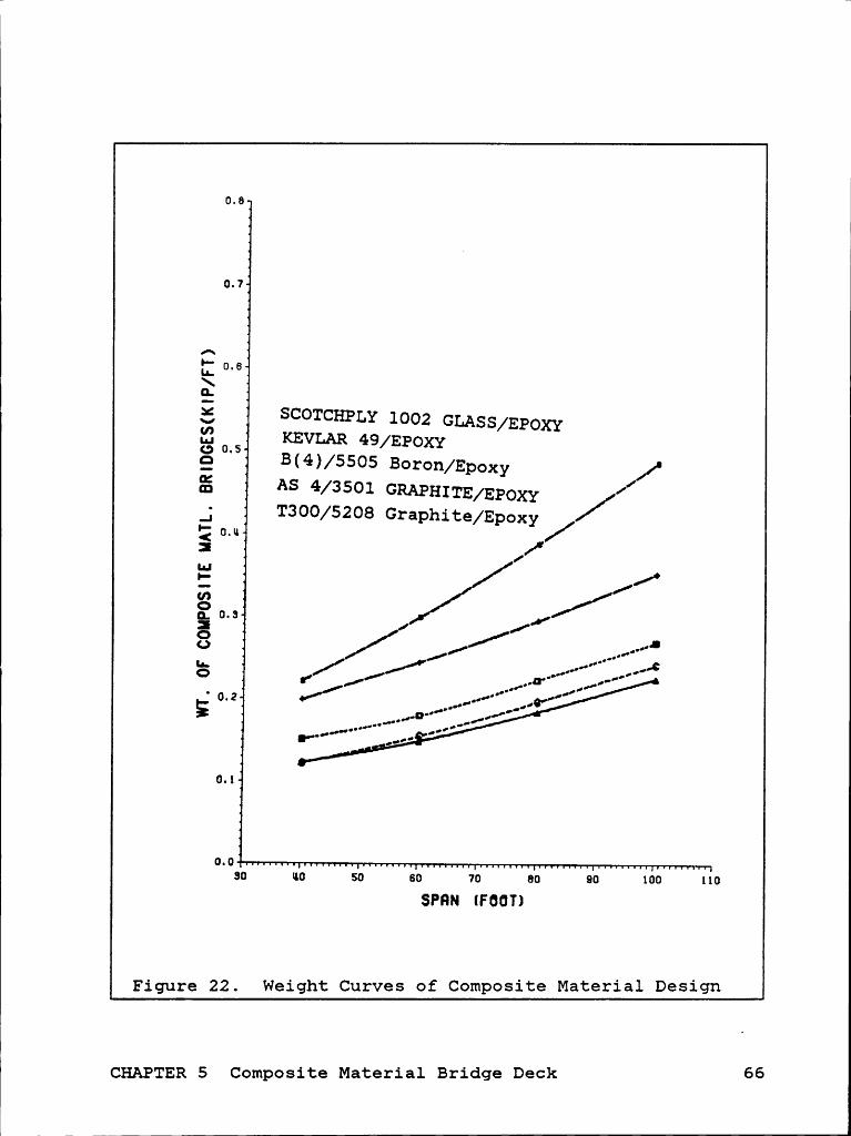
The results of different cases of Composite Material
Bridge Decks are shown in Figure 22 and data are listed in
Appendix D.
5-§ weight gf Sghgggghg
From Figure 22 shown, T300/5208 graphite/epoxy weighs
the least and glass/epoxy weighs the most. The weight of
glass/epoxy composite bridge decks is about twice as much as
those of TBOO/5208 graphite/epoxy. However, the per pound
CHAPTER 5 Composite Material Bridge Deck 64

u
'WüGHTOFRMßßüw8BREßBSü§MN=MWEEU180
· 170
V 180AI-1,,, 150\~G.1OU')Ln-IégxmZGIn-O
§ 130
120
110
1000 11 8 12 18 20 211 28 32
GIHDEH HIDTH
Figure 21. Design Results ( DEPTH vs. WEIGHT )
CHAPTER 5 Composite Material Bridge Deck 65
V
0.8
0.7
0.6\E5:, SCOTCHPLY 1002 GLASS/EPOXY,8 0 5 KEVLAR 49/EPOXYQ B(4)/5505 BOI‘0n/Epoxy /°gg AS 4/3501 GRAPHITE/EPOXY_; T300/5208 Graphite/Epoxy /•-< 0.*1 /: Ix"EE / //•01 0.6
·‘__,..l0. ,/’
_,..····‘°" _,.»¢° 0.2 •// __,.„··*"°· _.0·"/
I"°°“·“·" ,.•¢' l"
0.1
0.030 H0 S0 60 70 80 90 100 110
SPHN 1FOOT)
Figure 22. Weight Curves of Composite Material Design
CHAPTER 5 Composite Material Bridge Deck 66

price of glass/epoxy is much lower than any of the othercomposite materials considered here.
CHAPTER 5 Composite Material Bridge Deck 67

I
CHAPTEg 6 RESULTS AND DISCUSSION
According to the results derived in chapters 3, 4, and
5, three different design models are compared and discussed
with regard to design characteristics, weight, and de-.
flection. In addition, maintenance, construction method, fa-
tigue behavior, shrinkage and thermal effects, and cost are
also discussed in this chapter.
6-1 Cbagactegistics of Desigg
Essentially, all three designs concentrate on three most
important design drivers - moment, shear, and deflection.
The concrete T·beam has shear reinforcements and large
cross sectional area to resist shear loads. Except for short
span bridges, shear resistance usually does not control con-
crete T-beam bridge design. This point can be realized simply
by looking at the how the required shear and moment strength
increases as a function of span in Table 1. Required moment
strength increases much faster than required shear strength.
That is, flexural resistance will control the design of mod-
erate span bridges before shear stress reaches the allowable
value. Since the area moment of inertia of a concrete T-beam
CHAPTER 6 Results and Discussion 68
is relatively large, the deflection requirement is usually
satisfied.
Steel-concrete composite sections have large concrete
slabs as do T-beams, but the concrete slab does not contrib-
ute much to shear resistance. In order to simplify the design
process, shear load is considered to be taken by the web of
the steel beam. As in concrete T-beams, moment resistance
controls the design of steel-concrete composite sections.
Usually, when a W-section steel beam is selected for moment
resistance of bridge design, the web area will be large
enough for shear resistance. However, shear stiffners can be
used if needed.
Due to the geometry of the cross section selected, com-
posite material bridge decks have much a smaller area moment
of inertia. Even though the stiffness for some of the com-
posites is high, deflection control is the most critical
point of the design. The design results show that the
stress/strength ratios of composites are low. This means that
the materials are not fully utilized„ To achieve better
utilization of material, different cross sectional geometry
can be used; for example, uneven thickness girder.
Composite material bridge deck design in this thesis
considered only macromechanical design of the bridge deck.
CHAPTER 6 Results and Discussion 69

However, micromechanical behavior of composite materials is
as important as the macromechanical behavior. In future de-
sign consideration, micromechanical behavior should be in-
cluded.
Q-g weight of Ihree Desigg Models
Figure 23 and Table 4 show that composite material bridges
weigh much less than concrete T-beam bridges and steel-
concrete composite bridges for those designs considered in
this study. By comparing glass/epoxy bridges with other non-
composite material bridges, glass/epoxy has a weight approx-
imately 16% of concrete T-beam. 'bridge or 23% of
steel-concrete composite bridge. This is a dramatic saving
in weight. Several reasons contribute to these results.
First, glass/epoxy has a specific density only 75% of that
of the reinforced concrete. Second, the strength of
glass/epoxy is much higher than those of concrete and steel.
Third, the longitudinal stiffness of glass/epoxy is higher
than that of concrete. Fourth, the geometric shape of com-
posite materials is flexible.
CHAPTER 6 Results and Discussion3
70

Table 4. Weight of Designs (lb/foot/lane)
SPAN <PSSP> 40 ÄZK APPCONCRETET-BEAM 1644 1900 2440 2946STEEL-CONCRETECOMPOSITE BEAM 1186 1266 1650 2070T300/5208Graphite/Epoxy 123 149 185 225B(4>/Ep¤xyBoron/Epoxy 151 180 223 270AS/3501Graphite/Epoxy 122 155 197 242Scotchply 1002Glass/Epoxy 221 300 389 487Kevlar 49Kevlar/Epoxy 199 245 296 353
6-3 Maintenance and gegain
Generally speaking, the expected service life of a con-
crete structure is about 40 years. Not much maintenance is
required unless damage occurs. Corrosion is a puoblem for
steel beams. In some of cases, steel beams are covered by
concrete for protection, but this method substantially in-
creases dead load. Sometimes the steel beam is designed to
have thicker dimensions to compensate for a corroded part.
This also increases construction cost, and the appearance is
bad. Painting is the most popular method of protection, but
regular maintenance is required.
CHAPTER 6 Results and Discussion 71

I
u. 0
3. 5
3. 0
C „;J>"'< ,<>§;as 'G¥§J
WHJOQ— 2. 0¢
.1•I<'* 1. S rate
;1. 0
' alß0. 5 Composite
0. 04 30 110 S0 80 70 80 90 100 110
SPRN (FOOT)
Figure 23. Weight of Designs
CHAPTER 6 Results and Discussion 72

When damage occurs or service requirements are changed,
replacement or reconstruction of all or part of the bridge
often takes as long as (sometimes even longer than) con-
structing a new bridge. In order to decrease the interruption
of traffic flow, a temporary bridge is sometimes required.
Thus, the cost may be very high.
Maintenance requirements of composite material bridge
decks are not known, but the reliable design can be used to
achieve a maintenance free composite design during the life
of the structure. When part of the bridge is damaged, com-
posite material bridges may take less time and money to re-
place or repair since they are light weight and easy to
handle.
6-9 Constructiog Methods
Concrete is used in both T-beam bridges and Steel-concrete
composite bridges. Appropriate forms and shores are required
to provide shape and support of concrete paste. After the
concrete paste has been put into forms, it is necessary to
cure the concrete paste for about seven days before the forms
and shores can be taken away. Precast concrete members can
be used to shorten construction time, but high weight capac-CHAPTER 6 Results and Discussion 73

ity lifting equipment will be needed to locate the precast
members.
Composite material bridge decks can be made close to the
site of the bridge if appropriate equipment is provided. This
will reduce the work involved in shipping and handling. Even
though the initial cost of delivering the equipment is
needed, the requirements on the weight lifting equipment will
be much less than that of precasted concrete members because
the composite materials are light weight. In addition, floor
beams and girders can be handled separately.
6-; Eatigue
Fatigue failure is not a problem for concrete. In fact,
strength of concrete increases as a function of time. Yet
when steel is used as reinforcement, fatigue behavior of the
bridge structures involving steel become very important since
the loading on the bridge is cyclic.
Fatigue behavior of composite materials is generally muchbetter than those of metals because the internal damping of
composite materials is high. In addition, initial
imperfections such as cracks can be larger than those of
metals. Fatigue failure of composite materials requires con-
sideration of the fatigue sensitivity of matrix, interfacial
CHAPTER 6 Results and Discussion 74

‘
·
effects, and fiber type. Experimental results (Tsaig chapter
19) show that graphite/epoxy composites have relatively
flatter S—N curves than those of metals, especially in the
case of unidirectional laminates. After one million cycles,
they still have 80% of the initial static strength. Since the
stress level in composite material designs is well below the
static strength of the materials, reduction in strength due
to cyclic load is not as important as reduction in stiffness.
The modulus reduction of composite materials is mainly a re-
sult of ply cracks and delamination. Test results (Tsaig
pp19-12) show that graphite/epoxy with [0/45/90/ — 45]S stacking
sequence will degrade about 25% on its modulus after 105 cy-
cles. The results of unidirectional laminates tend to be
better because graphite fiber is insensitive to fatigue. For
other fiber systems, fatigue behavior may vary. However, as
long as the internal damping remains high, fatigue behavior
of composite materials will be better than metals.
Q-Q Shgingage agg Ibegmgg gffects
As concrete shrinks during the curing process, a differ-
ence of strain is introduced between concrete and steel.
Shrinkage strain results tensile stress to concrete and
compressive stress to steel. A strain value of 0.0002
inch/inch is usually assumed for the purpose of shrinkage
CHAPTER 6 Results and Discussion 75

stress calculation. Since concrete is designed. to resist
compressive stress only, the cracks that are caused by
shrinkage have minimal effect on the capacity of concrete.
Because the difference of coefficient of thermal expan-sion between concrete (0.00055/VF) and steel (0.00065/VF) is
small, stresses induced by thermal effects are usually ig-nored. In some of the cases, however, especially steel-
concrete composite beams in hot and sunny weather, the
temperature difference between concrete slab and steel beamsis large since the steel beams are shaded and the concrete
slab is not.
For composite material bridge decks, thermal effects will
result in interlaminar stresses. Delamination may be caused ,
by cyclic temperature change. In addition, bearing stresses
induced by thermal displacement may cause bearing failure
because the bearing strength of composite materials is low.
Thus the thermal effects should be carefully considered in
future work.
Q-1 ggjlgcgigg
As shown in Figure 24, T-beam bridges have the smallest
deflection of those considerred. Composite material bridges
have the largest deflection. Since the designs of composite
CHAPTER 6 Results and Discussion 76

materials are constrained by deflection requirements, if the
maximum allowable deflection can be somewhat released, moreweight saving in composite material bridges are expected.
6-8 Cost
The costs of bridge construction depend on many factors.
By comparing major factors that affect the costs, relative
costs can be obtained. Several major factors that affect the
costs most are listed and compared in Table 5.
[ CHAPTER 6 Results and Discussion 77

II
DEFLECTION OF BRIDGES VS. SPAN2.0 6
1.8
1.6,3
E 1.11 ye, I,/'E L6 ,1v1.2o
Oe · .,9 ,sQ Q / O·<« „·1: 1 0 o‘° / <·> /• O QQ .-*— / ¤,'° /¤ I 06ä 0.8 / QQQ
- / oE3 ¤/ $0 ·gg ,/ 46 /__] // O att. ¤—¤ = (,6* / uxcso
. q,"* ./t0.u{0.2
0.030 110 so B0 70 80 00 100 110SPFIN (FOOTl
Figure 24. Deflection of Three Design Models
CHAPTER 6 Results and Discussion 78

Table 5. Factors Affecting The Cost Of Bridges
Concrete Steel Concrete CompositeT-beam Composite MaterialBridge Bridge Bridge
Unit price of very low low highraw materialNormalizedWeight Of 1.0 0.08 to 0.16StructureForms required required not requiredShores required depends not requiredMaintenance low paint job lowRequirement neededTime forRepair and long long shortConstructionService Life long long depends on
materialsFatigue fair fair goodBehaviorsNormalized l.0(based on 0.5Area of Post normal forceRequired required)Transportationand Weight High High LowLiftingRequirementsDesign Easy Easy Complicated
and Short ofExperience
CHAPTER 6 Results and Discussion 79
l CHAPTEB 7 SUMMARY AND CONCLUSION
lH With the design results shown, composite material bridge
decks appear very competitive to concrete T-beam and steel-l
concrete composite bridges. The advantages of using compos-,
ite materials as bridge deck structural materials are
lfollowing :
1. Weight saving of 84% to 92% on bridge decks and 50% on
supports compared to T-beam bridges. To steel-concrete
composite bridges, saving is 77% to 88% and 38% sepa-
rately.
2. Maintenance free design achievable.
3. Easy construction and repair.
4. Better fatigue behavior.
5. Flexible cross section.
6. No forms and shores required.
The disadvantages of using composite materials as bridge deck
structural materials are following :
1. High material costs.
2. Complicated design due to anisotropic material properties
and micromechanical behaviors.
3. Low bearing strength.
CHAPTER 7 Summary and Conclusion 80
h „4. Larger deflection.
5. Lack of practical experience.
Since the mechanical behavior of the composite materialsare very complicated and are not well known, design specifi-
cations according to AASHTOl should be modified in accordance
with experimental results and practical experience. In orderto accomplish a complete composite material bridge design,
more effort is needed. For instance :
Long term behavior of composite material bridge decks.
Different cross sections and configurations.
Different composite materials.
Connections.Composite material member manufacture.
Slenderness ratio vs. allowable stresses.Use of stiffners.Modification of specifications.
Composite material column design.
CHAPTER 7 Summary and Conclusion 81
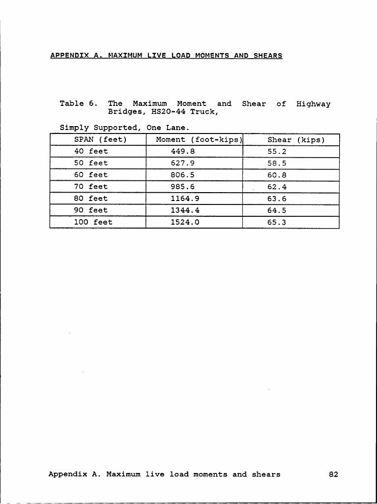
I I
I
APPENDIX A. MAXIMUM LIVE LOAD MOMENTS AND SHEARS
Table 6. The Maximum Moment and Shear of HighwayBridges, HS20-44 Truck,
Simply Supported, One Lane.SPAN (feet) Moment (foot-kips) Shear (kips)40 feet 449.8 55.250 feet 627.9 58.560 feet 806.5 60.870 feet 985.6 „ 62.480 feet 1164.9 63.690 feet 1344.4 64.5100 feet 1524.0 65.3
Appendix A. Maximum live load moments and shears 82
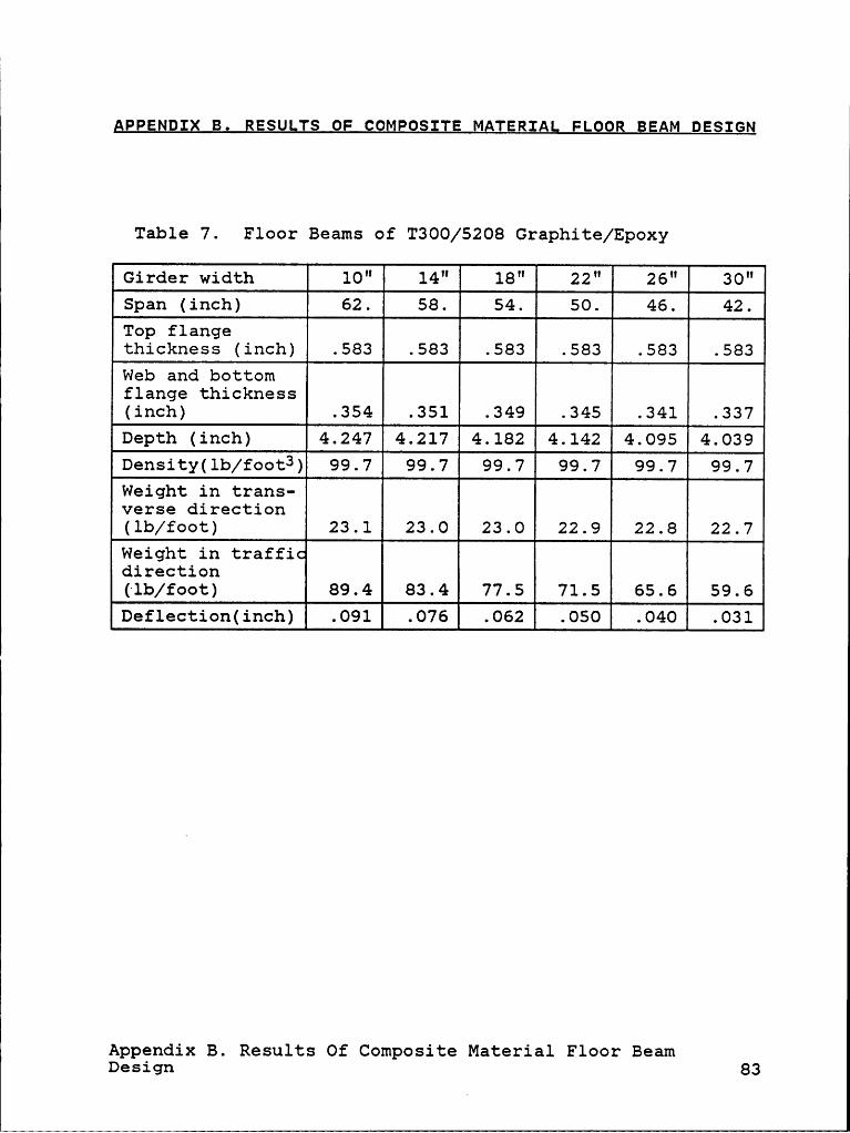
APPENDIX B. BESULTS OF COMPOSITE MATERIAL FLOOR BEAM DESIGN
Table 7. Floor Beams of T300/5208 Graphite/Epoxy
Girder width 10" 14" 18" 22" 26" 60"Span (inch) 62. 58. 54. 60. E 42.Top flangethickness (inch) .583 .583 .583 .583 .583 .583Web and bottomflange thickness(inch) .354 .351 .349 .345 .341 .337Depth (inch) 4.247 4.217 4.182 4.142 4.095 4.039Density(1b/foot3) 99.7 99.7 99.7 99.7 99.7 99.7Weight in trans-verse direction(lb/foot) 23.1 23.0 23.0 22.9 22.8 22.7Weight in traffi•direction(lb/foot) 89.4 83.4 77.5 71.5 65.6 59.606£16ct16¤(1¤ch) .091 .076 .062 .060 .031
Appendix B. Results Of Composite Material Floor BeamDesign 83

Table 8. Floor Beams of B(4)/5505 Boron/Epoxy
Girder width 10" 14" 18" 22" 26" 30"Span (inch) 62. 66. 54. 60. E 42.Top flangethickness (inch) .586 .586 .586 .586 .586 .586Web and bottomflangethickness(inch) .357 .354 .351 .348 .344 .339Depth (inch) 4.280 4.249 4.214 4.174 4.126 4.070Density(1b/foot3) 124.6 124.6 124.6 124.6 124.6 124.6Weight in trans-verse direction(lb/foot) 29.0 29.0 28.9 28.8 28.7 28.6Weight in traffi•direction(lb/foot) 112.5 105.0 97.5 82.5 75.0Deflection (inch) .078 .065 .053 .043 .034 .027
Appendix B. Results Of Composite Material Floor BeamDesign 84
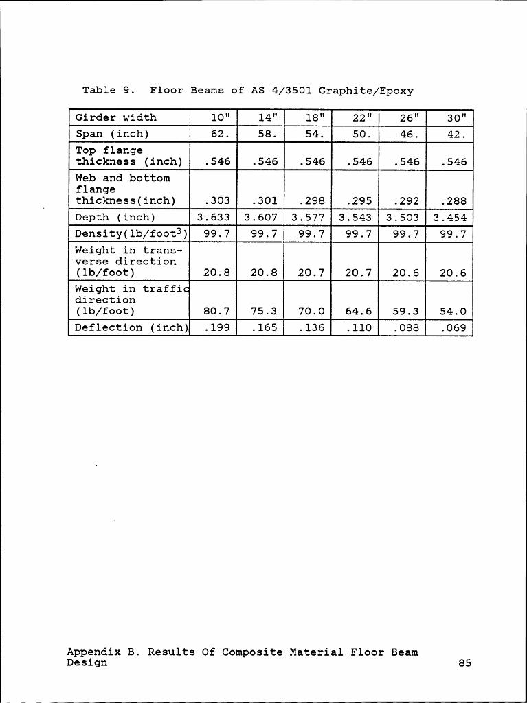
11
Table 9. Floor Beams of AS 4/3501 Graphite/Epoxy
Girder width 10" 14" 18" 22" 26" 30"Span (inch) 62. 69. 64. 60. E 42.Top flangethickness (inch) .546 .546 .546 .546Web and bottomflange
' thickness(inch) .303 .301 .298 .295 .292 .288Depth (inch) 3.633 3.607 3.577 3.543 3.503 3.454Density(lb/foot3) 99.7 99.7 99.7 99.7 99.7 99.7Weight in trans-verse direction(lb/foot) 20.8 20.8 20.7 20.7 20.6 20.6Weight in traffi•direction(lb/foot) 80.7 75.3 70.0 59.3 54.00a£1ac1;1cn (inch) .199 .165 .136 .110 .088 ß
Appendix B. Results Of Composite Material Floor BeamDesign 85

1
Table 10. Floor Beams of Scotchply 1002 Glass/Epoxy
Girder width 10" 14" 18" 22" 26" 30"Span (inch) 62. 66. 54. so. E 42.Top flangethickness (inch) .840 .840 .840 .840 .840 .840Web and bottomflange _thickness(inch) .344 .342 .339 .336 .332 .327Depth (inch) 4.130 4.100 4.066 4.027 3.982 3.927Density(1b/foot3) 112.1 112.1 112.1 112.1 112.1 112.1Weight in trans-verse direction(lb/foot) 35.2 35.1 35.1 35.0 34.9 34.8Weight in traffi-direction(lb/foot) 136.3 127.3 118.3 109.3 100.3 91.3Deflection (inch) .415 .346 .285 .231 .185 .145
Appendix B. Results 0f Composite Material Floor BeamDesign 86
1 1

Table 11. Floor Beams of Kevlar 49/Epoxy
Girder width 10" 14" 18" 22" 26" 30"Span (inch) 62. 58. 54. 60. ß 42.Top flangethickness(inch) 1.352 1.352 1.352 1.352 1.352 1.352Web and bottom
_ flangethickness(inch) .501 .497 .493 .488 .483 .476Depth (inch) 6.009 5.967 5.918 5.861 5.794 5.714Density(1b/foot3) 91.0 91.0 91.0 91.0 91.0 91.0Weight in transverse direction(lb/foot) 47.4 47.3 47.2 47.1 46.8Weight in traffi•direction(lb/foot) 183.8 171.6 159.4 147.2 135.0 122.8Deflection(inch) .057 .047 .039 .032 .025 .020
Appendix B. Results Of Composite Material Floor BeamDesign 87

APPENDIX C. FORTRAN PROGRAM "DECK"
* DESIGN OF COMPOSITE BRIDGE DECK* B : WIDTH OF GIRDER ( INCH )* BOT : RATIO OF B/T* D : DEPTH OF GIRDER ( INCH )* DEFL : DEFLECTION ( INCH )* DOB : RATIO OF D/B* EIR : EX*IX REQUIRED FOR DEFLECTION* (KIP*IN**2)* EX,EY : EALSTIC MODULI (MSI)* IMP : IMPACT FACTOR* IX : MOMENT OF INERTIA IN X DIRECTION* L : CLEAR SPAN ( FEET )* MATL : NAME OF MATERIALS* ML, MD, MR : LIVE, DEAD, AND RESISTING MOMENT* (FEET-KIP,ONE LANE)* RHO : DENSITY OF MATERIALS (LB/FEET**3)* S : SHEAR STRENGTH (KSI)* SIGX : FLEXURAL STRESS (KSI)* T : THICKNESS OF GIRDER ( INCH )* TAUX : SHEAR STRESS (KSI)* VL, VD, VR : LIVE, DEAD, AND RESISTING SHEAR* (KIP,ONE LANE)* WD : DISTRIBUTED DEAD LOAD ( KIP/FEET,* ONE LANE )* XC,XT,YC,YT: STRENGTHS OF MATERIALS(KSI)* REAL L(7),ML(7),IMP(7),MD(7),MR(7),IX
CHARACTER MATL(5)*30DIMENSION VL(7),VD(7),VR(7),EX(5),EY(5),EIR(7),‘* XT(5).XC(5)„YT(5)„YC(5)„S(5),RHO(5)
******************************************************** INPUT SPAN—LENGTHES (FEET), LIVE-LOAD-MOMENTS,* LIVE-LOAD-SHEARS 7 SETS OF DATA, SPAN FROM 40 TO 100 FEET
DO 10 I=l,710 READ(5,*)L(I),ML(I),VL(I)
***************+************************************** INPUT MATERIAL PROPERTIES* 5 MATERIALS
DO 20 I=1,5READ(5,*)MATL(I),EX(I),EY(I),XT(I),XC(I),YT(I),
*YC(I),$(I),RHO(I)* FOR LAMINATE, CONSIDER ONLY 85% OF THE PROPERTIES IN* PRINCIPAL DIR.
EX(I)=.85*EX(I)
Appendix c. FoRTRAN pR¤cRAM "¤EcK" 88

1
EY(I)=.85*EY(I)XT(I)=.85*XT(I)XC(I)=.85*XC(I)YT(I)=.85*YT(I)YC(I)=.85*YC(I)
20 S(I)=.85*S(I)
* INPUT WIDTH/THICKNESS RATIOS, INITIAL WD ASSUMEDREAD(5,*)BOT,WD
* I : ORDER OF SPAN, 40 FEET IS 1, 50 FEET IS 2, ETC.* UNTIL I=7* M : MATERIAL TYPE, 1 FOR T300/5208, 2 FOR BORON/EP,* 3 FOR AS350l GR/EP* 4 FOR SCOTCHPLY GL/EP, 5 FOR KEVLAR/EP* B : GIRDER WIDTH (IN INCH)* IG: 1 FOR ANOTHER CASE FOLLOWING, 0 FOR NONE* RATIO : ALLOWABLE D/T·OR B/T RATIO
25 READ(5,*)I,M,B,IG,RATIO* IC : CONTROLLER, PREVENT FROM BAD WD DERIVED
IC=O
* DERIVE IMPACT FACTORCALL IMPFAC(L(I),IMP(I))
******************************************************** ELASTIC DESIGN, CALCULATE REQUIRED MOMENT AND SHEAR* RESISTANCES
30 CALL ED(ML(I),VL(I),MD(I),VD(I),MR(I),VR(I),L(I),*WD,IMP(I))
* ELASTIC DESIGN, CALCULATE REQUIRED EI VALUE TO FULFILL* DEFLECTION REQUIREMENT
CALL EIREQ(L(I),IMP(I),EIR(I))WRITE(6,200)MATL(M)
200 FORMAT(5X,°MATERIAL °,A27)******************************************************** DETERMINE DEPTH OF GIRDER FROM DEFLECTION REQUIREMENT
CALL NEWTON(B,D,T,EIR(I),EX(M),RATIO)******************************************************** FLOOR BEAM DESIGN
EF=(EX(M)+EY(M))/.85/2.CALL FBW(B,RHO(M),XT(M),XC(M),S(M),WDB,EX(M),EF)
******************************************************** DERIVE NEW WD
CALL NEWWD(RHO(M),WDB,B,D,T,WDl,WDG)
* WITH NEW WD DERIVED, CHECK ASSUMED WD AND REDESIGN GIRDER* IF NECESSARY
IF (ABS(WD1/WD-1.) .GT .03) THENWD=WD1
Appeudix C. FORTRAN PROGRAM "DECK" 89
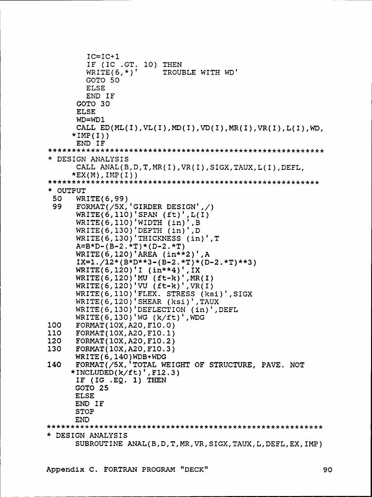
IlI
IC=IC+lIF (IC .GT. 10) THENwR1TE(6,*)' TROUBLE w1TH wD'GOTO 50ELSEEND IF
GOTO 30ELSEWD=WD1*$ä;%I??(ML(I),VL(I)„MD(I)„VD(I),MR(I)„VR(I)„L(I)„WD„END IF
* DESIGN ANALYSISCALL ANAL(B,D,T,MR(I),VR(I),SIGX,TAUX,L(I),DEFL,
*EX M ,IMP I********i*l****i*ll*********************************4***** OUTPUT
50 WRITE(6,99)99 FORMAT(/5X,°GIRDER DESIGN',/)
WRITE(6,110)'SPAN (ft)°,L(I)WRITE(6,110):WIDTH (1u):,BWRITE(6,130) DEPTH (1u) ,DWRITE(6,130)°THICKNESS (i¤)°,TA=B*D-(B-2.*T)*(D-2.*T)WRITE(6,120)'AREA (in**2)',AIX=1./12*(B*D**3-(B-2.*T)*(D-2.*T)**3)WRITE(6,120)°I (in**4)°,IXWRITE(6,120)°MU (ft—k)°,MR(I)WRITE(6,120)°VU (ft-k)°,VR(I)WRITE(6,110)°FLEX. STRESS (ksi)°,SIGXWRITE(6,120)'SHEAR (ksi)°,TAUXWRITE(6,l30)°DEFLECTION (i¤)°,DEFLwR1TE(6,130)'wc (k/ft)',WDG
100 _ FORMAT(l0X,A20,F10.0)110 FORMAT(10X,A20,F10.1)120 FORMAT(10X,A20,F10.2)130 FORMAT(10X,A20,F10.3)
WRITE(6,l40)WDB+WDG140 FORMAT(/5X,°TOTAL WEIGHT OF STRUCTURE, PAVE. NOT
*INCLUDED(k/ft)',F12.3)IF (IG .EQ. 1) THENGOTO 25ELSEEND IFSTOPEND
*********************************************************** DESIGN ANALYSIS
SUBROUTINE
Appendix C. FORTRAN PROGRAM "DECK" 90
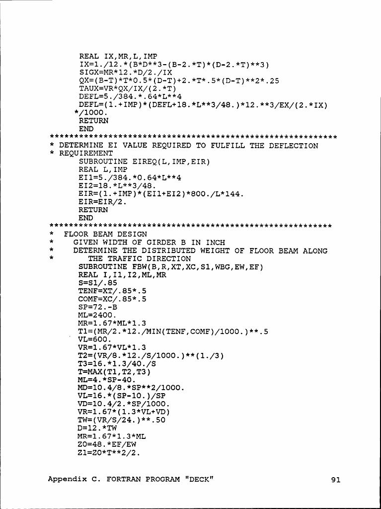
I
REAL IX,MR,L,IMPIX=1./12.*(B*D**3—(B-2.*T)*(D-2.*T)**3)SIGX=MR*l2.*D/2./IXQX=(B-T)*T*0.5*(D-T)+2.*T*.5*(D—T)**2*.25TAUX=VR*QX/IX/(2.*T)DEFL=5./384.*.64*L**4DEFL=(1.+IMP)*(DEFL+18.*L**3/48.)*12.**3/EX/(2.*IX)
*/1000.RETURNEND
************************************************************ DETERMINE EI VALUE REQUIRED TO FULFILL THE DEFLECTION* REQUIREMENT
SUBROUTINE EIREQ(L,IMP,EIR)REAL L,IMPEI1=5./384.*0.64*L**4EI2=18.*L**3/48.EIR=(1.+IMP)*(EI1+EI2)*800./L*144.EIR=EIR/2.RETURNEND
***********************************+*********************** FLOOR BEAM DESIGN* GIVEN WIDTH OF GIRDER B IN INCH* DETERMINE THE DISTRIBUTED WEIGHT OF FLOOR BEAM ALONG* THE TRAFFIC DIRECTION
SUBROUTINE FBW(B,R,XT,XC,S1,WBG,EW,EF)REAL I,Il,I2,ML,MRS=S1/.85TENF=XT/.85*.5COMF=XC/.85*.5SP=72.-BML=2400.MR=l.67*ML*1.3T1=(MR/2.*12./MIN(TENF,COMF)/1000.)**.5‘VL=600.VR=1.67*VL*1.3T2=(VR/8.*12./S/1000.)**(1./3)T3=16.*1.3/40./ST=MAX(T1,T2,T3)ML=4.*SP-40.MD=l0.4/8.*SP**2/1000.VL=l6.*(SP-10.)/SPVD=10.4/2.*SP/1000.VR=1.67*(l.3*VL+VD)TW=(VR/S/24.)**.50D=l2.*TwMR=l.67*l.3*MLZ0=48.*EF/EWZ1=Z0*T**2/2.
Appemdix c. EoRTRAN PROcRAM "DEcx" 91

Z2=2.*(TW*(D—T-TW)*.5*(D-TW+T/2.))Z3=2.*(D*TW*(D-.5*TW))Z4=Z1+Z2+Z3Z5=T*ZO+(D*2.+(D—T—TW)*2.)*TWXB=Z4/Z5I1=ZO*T**3/12.+ZO*T*(XB—T/2.)+2*(D*TW)*(D-XB—TW/2.)**2I2=2.*(TW*(D-TW—TE))*((D—TW-TF)*.5+T-XB)**2+
*TW/l2.*(D-T-TW)**3I=I1+I2SC=MR*XB/IST=MR*(D-XB)/I _IF (ST .GT. XT) THENWRITE(6,15)SC,XT
15 FORMAT(' MOMENT RESISTANCE NOT SATISFIED ',2F10.2)ELSEEND IFCALL DEFLECTION(SP,DEFL,EW,I)A=(48.*T+(4.*D-2.*T-2.*TW)*TW)/144.WDT=R*AWBG=WDT*SP/48.*2.*1.5WRITE(6,lOO)BWRITE(6,101)SPWRITE(6,102)TWRITE(6,103)TWWRITE(6,104)DWRITE(6,105)RWRITE(6,lO6)WDTWRITE(6,107)WBGWBG=WBG/1000.WRITE(6,108)DEFL
100 FORMAT('Girder width(inch)',F5.0)101 FORMAT('Clear span (inch)',F5.0)102 FORMAT('Top flange thickness (inch)',F5.3)103 FORMAT('Web and bottom flange thickness(inch)',F5.3)104 FORMAT('Depth (inch)',F5.3)105 ‘ FORMAT('Density (lb/foot**3)’,F5.l)106 FORMAT(’Weight in transverse direction (lb/foot)',
*F5.1)107 FORMAT('Weight in traffic direction (lb/foot)',
*E5.1)108 FORMAT('Def1ection (inch)',F5.3)
RETURNEND
*********************************************************** DETERMINE FLOOR BEAM DEFLECTION
SUBROUTINE DEFLECTION(B,DEFL,E,I)REAL IEI=E*IY=(B-20.)/2.DEFL=1./6.*B**3+O.8*Y**4/48.-
Appenaix c. FoRTRAN PRocRAM "DEcK" 92

*0.8*(B**4/256.·Y*B**3/48.+Y*Y*B*B/32.)DEFL=DEFL*2./EI*l000.*1.3RETURNEND
********************************************************* DETERMINE IMPACT FACTOR
SUBROUTINE IMPFAC(L,IMP)REAL L,IMPIMP=50./(L+12S.)IF (IMP .GT. 0.3) THENIMP=O.3ELSEEND IFRETURNEND
******************************************************* ELASTIC DESIGN TO DETERMINE DESIGN LOAD
SUBROUTINE ED(ML,VL,MD,VD,MR,VR,L,WD,IMP)REAL ML,MD,MR,L,IMPMD=0.125*WD*L**2VD=.5*wD*LMR=1.67*(MD+(1.+IMP)*ML)VR=l.67*(VD+(1.+IMP)*VL)MR=MR/2.VR=VR/2.RETURNEND
********************************************************* NEWTON METHOD IS USED TO DETERMINE DEPTH REQUIRED TO* FULFILL DEFLECTION REQUIREMENT
SUBROUTINE NEWTON(B,D,T,EIR,E,RATIO)I=OD=40.
10 T=MAX(B,D)/RATIOCl=T/6.' C2=T/2.*(B—2.*T)C3=-T**2*(B-2.*T)C4=+T**3*8./12.*(B-2.*T)-EIR/(E*1000.)F=Cl*D**3+C2*D*D+C3*D+C4FP=3.*C1*D*D+2.*C2*D+C3D1=D-F/FP
I=I+lIF (I .GT. 10) THEN ’WRITE(6,*)°NEWTON°°S METHOD FAILED°RETURNELSEEND IF
IF (ABS(D1-D) .LT. .01) THEND=DlRETURN
Appendix C. FORTRAN PROGRAM "DECK" 93
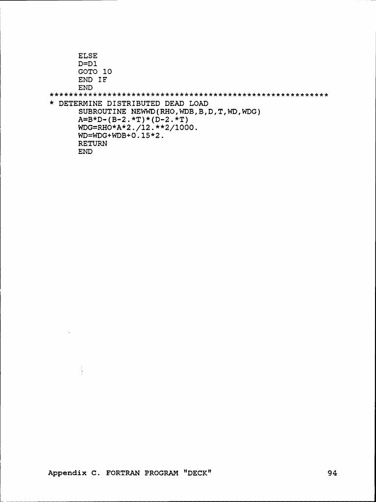
\„
ELSED=DlGOTO 10END IFEND
**********4*******4***********************4**************** DETERMINE DISTRIBUTED DEAD LOAD
SUBROUTINE NEWWD(RHO,WDB,B,D,T,WD,WDG)A=B*D-(B—2.*T)*(D—2.*T)WDG=RHO*A*2./12.**2/1000.WD=WDG+WDB+0.15*2.RETURNEND
Appendix c. FoRTRAN PRccRAM "¤EcK" 94

r
APPENDIx D. RESULTS OF GIRDER DESIGN
Table 12. T300/5208 Graphite/Epoxy
Girder width(inch) 24.0 30.0 30.0 30.0
(kips/foot)SPAN (1:661:) 80.0 100.0Girder depth (inch) 24.610 31.792 39.724 47.295Thickness (inch) .410 .530 .662 .788Area ( inchz ) 39.20 64.35 90.59 119.35I ( inch4 ) 3803.43 10329.5 21407.7 38125.1Mu (foot-kips) 558.90 1024.0 1534.0 2103.2Vu (kips) 66.98 75.73 82.26 88.56Flex. stress (ksi) 21.7 18.9 17.1 15.7Shear stress (ksi) 3.80 2.85 1.83 1.42Deflection (inch) 0.900 1.200 1.500Girder weight .054 0.089 .125 .165(kips/foot)Total weight of .123 0.149 .185 .225structure(kips/foot)
Appendix D. Results of girder design 95

Table 13. B(4)/5505 Boron/Epoxy
Girder width (inch) 24.0 30.0 30.0 30.0Floor beam weight .086 .075 .075 .075(kips/foot)SPAN (feet) 80.0 100.0Girder depth (inch) 23.600 30.635 38.303 45.622Thickness (inch) E .511 .639 .760Area ( inchz ) 37.44 60.89 85.60 112.67I ( inch4 ) 3374.1 9163.6 18991.2 33821.7Mu (foot-kips) 563.58 1035.9 1559.4 2150.2Vu (kips) 67.45 76.52 83.53 90.44Flex. stress (ksi) 23.7 20.8 18.9 17.4Shear stress (ksi) 4.08 2.80 2.00 1.55Deflection (inch) 0.900 1.200 1.500Girder weight .065 0.105 .148 .195(kips/foot)Total weight of .151 0.180 .223 .270structure(kips/foot)
Appendix D. Results of girder design 96

1Table 14. AS 4/3501 Graphite/Epoxy
Girder width (inch) 26.0 30.0 30.0 30.0Floor beam weight .059 .054 .054 .054(kips/foot)SPAN (feet) 80.0 100.0Girder depth (inch) 26.262 34.556 43.130 51.301Thickness (inch) .438 .576 .719 .855Area ( inchz ) 44.99 73.02 103.09 136.09
l
I ( inch4 ) 4989.5 13550.8 28083.5 50014.2Mu (foot—kips) 558.67 1026.4 1541.7 2121.5Vu (kips) 66.96 75.89 82.65 89.29Flex. stress (ksi) 17.6 15.7 14.2 13.1Shear stress (ksi) 3.33 2.21 1.58 1.22Deflection (inch) E 0.600 1.200 1.500Girder weight .062 0.101 0.143 .188(kips/foot)Total weight of .122 0.155 .197 .242structure(kips/foot)
Appendix D. Results of girder design 97

fTable 15. Scotchply 1002 Glass/Epoxy
Girder width (inch) 30.0 30.0 30.0 30.0Floor beam weight .091 .091 .091 .091(kips/foot)SPAN (feet) 80.0 100.0Girder depth (inch) 37.577 50.807 63.071 74.675Thickness (inch) .626 .847 1.051 1.245Area ( inchz ) 83.07 133.97 191.23 254.38I ( inch4 ) 17828.6 48419.7 100348.4 178711.4Mu (foot-kips) 572.22 1080.9 1670.3 2377.2Vu (kips) 68.62 79.52 89.08 99.52Flex. stress (ksi) 7.3 6.3EShear stress (ksi) 1.70 1.11 .83 .67Deflection (inch) E 0.600 1.200 1.500Girder weight .129 0.209 .298 .396(kips/foot)Total weight of .221 0.300 .389 .487structure(kips/foot)
Appendix D. Results of girder design 98

T hTable 16. Kevlar 49/Epoxy
Girder width (inch) 30.0 30.0 30.0 30.0Floor beam weight .123 .123 .123 .123(kips/foot)sp:-xu (feet) 60.0 100.0Girder depth (inch) 30.528 41.443 51.599 61.241Thickness (inch) .509 .691 .860 1.021Area ( inchz ) 60.58 96.77 137.37 182.07I ( inch4 ) 9059.9 24605.3 50993.7 90815.3Mu (foot-kips) 571.7 1060.3 1608.4 2236.8Vu (kips) 68.26 78.15 85.98 93.90Flex. stress (ksi) 11.6 10.7 9.1Shear stress (ksi) 2.52 1.61 1.17 .92oemeetmh (inch) E 0.900 1.200 1.500Girder weight .077 0.122 .174 .230(kips/foot)Total weight of .199 0.245 .296 .353structure(kips/foot)
Appendix D. Results of girder design 99

I
gEFERENCES
1. AASHTO, "Standard Specification for Highway Bridges",13th ed., American Association of State Highway andTransportation Officials 1983
« 2. ACI, "Building Code Requirements for Reinforced Con-crete", ACI 318-83 revised 1986, American Concrete In-stitute 1986
3. AISC, "Manual of Steel Construction - Load & ResistanceI Factor Design", 1st ed., American Institute of SteelI Construction 1986
4. Cook, QL P., "Composite Construction Methods", JohnWiley & Sons 1977
5. Halpin, J. C., "Primer on Composite Materials : Analy-sis", Technomic Publishing Co. Inc. 1984 .
6. Jones, R. M., "Mechanics of Composite Materials",Washington Scripta Book Company 1975
7. MacCormac, J. C., "Design of Reinforced, Concrete",Happer & Row Publishers 1978
8. MacGregor, J. G., "Reinforced Concrete - Mechanics andDesign", Prentice Hall 1988
9. Tsai, S. W., "Composite Design", 3rd ed., Think Com-posites 1987
10. Schwartz, M., "Composite Materials Handbook",McGraw-Hill Book Company 1984
11. Waddell, J., "Concrete Construction Handbook", 2nd ed.,McGraw-Hill Book Company 1974
12. Yam, C. P., "Design of Composite Steel-Concrete Struc-tures", Surrey University Press 1981
References 100
