in-820.48 installation, operation and … · installation, operation and maintenance instructions...
TRANSCRIPT
(
I \.
INSTALLATION, OPERATION AND MAINTENANCE INSTRUCTIONS
FEDERAL PACIFIC METAL-CLAD SWITCHGEAR
OCTOBER 1976
IN-820.48 www .
Elec
tricalP
artM
anua
ls . c
om

INDEX Page Part I. General . . . . . . . . . . . . . . . . . . . . . . . . . . . . . . . . . . . . . . . . . . . . . . . . . . . . . . I
Features . . . . . . . . . . . . . . . . . . . . . . . . . . . . . . . . . . . . . . . . . . . . . . . . . . . I Shipment . .... .. . ... .. .. . . . . . . . . . . . . . . . . . . . . . . . . . . . . .. . . . . . . I Inspection . . . . . . . . . . . . . . . . . . . . . . . . . . . . . . . . . . . . . . . . . . . . . . . . . . I Moving and Lifting .. . . . . . . . . . . . . . .. . . . . . .. . . . . .. . . . . .. . . . . . . I Storage . . . . . . . . . . . . . . . . . . . . . . . . . . . . . . . . . . . . . . . . . . . . .. . . . . . . . 6 Foundation . . . .. . . . . . .. . . . . . . . . . . . . . . . . . . . . . . . . . . . . . .. . . . . . . . 6
Part II. Installation Housing . . . .. . . . . . . . . . . . . . . . . . . . . . . . . . . . . . . . . . . . . . . . . . . . . . . . 7
Inspection . . . . . . . . . . . . . . . . . . . . . . . . . . . . . . . . . . . . . . . . . . . . . . 7 Assembly A-Protected Work Aisle . . . . . . . . . . . . . . . .. . . . . . . 7 Assembly B-Center Aisle . . . . . . . . . . . . . . . . . . . . . . . . . . . . . . . . 8 Assembly C-Non-Walk-in ............................... 8 Tightening Connections . . . . . . . . . . . . . . . . . . . . . . . . . . . . . . . . . . 8 Bus Duct . . . . .. . . . . . . . . . . . . . . . . . . . . . . . . . . . . . . . . . . . . . . . . . 8 Additions to Existing Equipment . . . . . . . . . . . . . . . . . . . . 8 and 13
Equipment Batteries .. . . . . .. .... . .. .. . . .... .. . . . . . . .. .. . . .. . ... . . . . I 3 Wiring .. . . . . . . . . . . . . . . . . . . . . . . . . . . . . . . . . . . . . . . . . . . . . . . . 13 Grounding . . . . . . . . . . . . . . . . . . . . . . . . . . . . . . . . . . . . . . . . . . . . . 13 Fuses . . . . . . . . . . . . . . . . . . . . . . . . . . . . . . . . . . . . . . . . . . . . . . . . . . 13 Dummy Breaker . . . . . . . . . . . . . . . . . . . . . . . . . . . . . . . . . . . . . . . . 13 Insulation
Taped Connections . . . . . . . . . . . . . . . . . . . . . . . . . . . . . . . . . . 14 Ground Fault CT Terminations . . . . . . . . . . . . . . . . . . . . . . . 14
Part Ill. Pre-energization Tests Preparation .. . . . . . . ... . . . . . . . . . . . . . . . . . . . . . . . . . . . . . . . . . . . . . . 16 Dielectric Tests . . . . . . . . . . . . . . . . . . . . . . . . . . . . . . . . . . . . . . . . . . . . . I 6 Operational Tests . . . . . . . . . . . . . . . . . . . . . . . . . . . . . . . . . . . . . . . . . . . I 6
Part IV. Maintenance Benefits .. . . . . . . . . . . . . . . . . . . . . . . . . . . . . . . . . . . . . . . . . . . . . . . . . . . I 7 Inspection . . . . . . . . . . . . . . . . . . . . . . . . . .. . . . . . . . . . . . . . . . . . . . . . . . I 8 Program . ... . . . . . . . . . . . . . . . . . . . . . . . . . . . . . . . . . . . . . . . . . . . . . . . 18
Part V. Safety Requirements for Power Switchgear Assemblies Unqualified Person-General Public ........................... 19 Qualified Person . . . . . . . .. . . . . . . . . . . . . . . . . . . . . . . . . . . . . . .. . . . . I 9 General Instructions to Qualified Persons . . . . . . . . . . . . . . . . . . . . . . . 19
Part VI. Switchgear Accessories Standard . . . . . . . . . . . . . . . . . . . . . . . . . . . . . . . . . . . . . . . . . . . . . . . . . . . 20 Indicating Lamps ............................................ 20 Miscellaneous ............................................... 20
List of Illustrations
Figure !-Lifting Gear-21 feet and Under (Dwg. 2200COI66) . . . . . . . . . . . . . 3 Figure 2-Lifting Gear-Over 21 feet (Dwg. 2200COI67) .................. 4 Figure 3-Recommend method of lifting indoor cells
(Dwg. 2200C335) . . . . . . . . . . . . . . . . . . . . . . . . . . . . . . . . . . . . . . . . . . . 5 Figure 4-Installation of Floor Channels-Indoor . . . . . . . . . . . . . . . . . . . . . . . . 6 Figure 5-Installation of Floor Channels-Outdoor . . . . . . . . . . . . . . . . . . . . . . 6 Figure 6-Table A-Shipping split . . . . . . . . . . . . . . . . . . . . . . . . . . . . . . . . . . . . . 8 Figure 7-Table B-Recommended Torque Values ....................... 8 Figure 8-Base Assembly (Dwg. 2200C0168) ............................ 9 Figure 9-0utdoor Protected Work Aisle Construction
(Dwg. 220000 I 69) .......................................... I 0 Figure 10-0utdoor Center-Aisle Construction
(Dwg. 220000 I 70) .......................................... 11 Figure 1 I-Base Connections and Cell Bolting
(
(Dwg. 2200COI7I) .......................................... I2 l_ Figure 12-Additions to Existing Units (Dwg. 2200COI72) ................. I2 Figure 13-Boot Installation ........................................... 14 Figure 14-Taping Instructions . . . . ...... . .... . . . .. . .. ;· ... . .. . ..... . .. . . 15 Figure 15-Table C-Dielectric Test Values .............................. I6 www .
Elec
tricalP
artM
anua
ls . c
om

(
METAL -CLAD SWITCHGEAR PART I - GENERAl CONSTRUCTION FEATURES INDOOR OR OUTDOOR: I. Switchgear Housings and DST-2 Air Circuit Breakers
are jig constructed in alignment fixtures to assure interchangeability of breakers. Compartmentalized construction segregates the circuit breaker, main bus, current transformers, potential transformers, and control power transformers.
2. Complete interlocking between the cell and circuit breaker provides safety to personnel and equipment by prevention of incorrect operating procedure.
3. Equipment is designed to reduce installation time, and to comply with A:\'SI Standards C37.20.
OUTDOOR: 4. Equipment is constructed so that additional sections
may be readily added in the field.
5. Protected work-aisle provides ample space for a scheduled maintenance program regardless of weather. Breakers draw out into aisle with sufficient space for interchangeability. The service area is ventilated, waterproof, and adequately lighted; service receptacles are provided.
6. The undercoated structural foundation supports are designed to be self-contained making it necessary to support foundation steel only. This design permits elevating switchgear on supporting structures and thereby reduces flood hazards.
7. Outdoor finish: Three-coat system consisting of a zinc chromate primer, an intermediate coat, and a final ASA-24 dark gray exterior coat.
SHIPMENT The switchgear is assembled, wired. adjusted and given complete tests at the factory. after which it is inspected and packed for shipment. The air circuit breakers are not shipped in the switchgear compartments, but are packed in separate crates. Each crate is identified, and a complete list of its contents is included in the shipping papers. All instruments and relavs are suitably blocked as required to prevent dam�ge to bear ings and movements.
Protected work-aisle metal-clad switchgear is shipped in completely assembled sections whenever possible to provide ease of handling and installing. See job assembly drawings and floor plans for details of shipping sections.
REMOVAL FROM CARRIER AND INSPECTION FOR DAMAGE Immediately upon receipt of the shipment, identify all component parts and check them against the shipping list. Make a thorough examination to detect any damage which may have been incurred during transit.
If any damage is discovered, file a claim immediately with the carrier. and send notice of the extent of the damage to the Federal Pacific Electric Company plant from which shipment was made, giving complete identification, carrier's name, and railroad car number if the shipment was made by rail.
The information will enable the company to supply necessary information in support of claim.
MOVING AND LIFTING SWITCHGEAR I. It is extremely important that care be taken in handl
ing, rigging, hoisting, rolling, or moving assembled switchgear into place. Metal-clad switchgear is designed to be handled only in an upright position and should never be handled in any other way without first consulting with the Switchgear Engineering Department.
INDOOR 2. Each shipping section of indoor switchgear is bolted
to a heavy shipping skid which should remain with the gear until it is moved into it's final location.
3. When cranes are not available, the gear can be rolled into place by applying pushing or pulling forces .Q!!.!y_ to the skid.
4. Remove shipping skid only when gear is at it's final location, by removing bolts inside the switchgear before lifting it from top as shown on drawing 2200C0335 (Fig. 3). If overhead lifting equipment is not available and bottom lifting provisions have been specified, proceed as follows and as shown in lifting drawing 2200C0335 (Fig. 3).
a. Remove all bolts located inside the switchgear that hold cells and skid together.
b. Completely remove the crating that encloses the switchgear.
c. Break-off skid extensions to allow the switchgear to sit flush with the remaining portion of the skid.
d. Open required front and rear doors and install the lifting channels as shown o n drawings www .
Elec
tricalP
artM
anua
ls . c
om

540006690 and 540006733 (shipped with the gear) for front and rear mountings.
e. Place jacks under every lifting station and adjust each jack until its piston or platform begins to exert force on the lifting channels.
f. Begin to raise the jacks, starting at one end of the switchgear assembly (both front and rear locations) with equal increments of strokes to provide equal height displacement in relationship of front to rear.
g. When the switchgear has sufficient clearance above the skid, remove. the skid.
h. With the skid removed lower the switchgear. If hydraulic jacks are used, release the p ressure in the jacks that support the center span (front and rear). Allow the switchgear to compress the jacks until there is no force exerted on the jacks. Then lock these jacks in this position. Release the pressure in the end jacks in the same manner as the
2
center span then lock in position. Continue a lternating between the center span and end jacks until the switchgear rests firmly on th1� ground surface.
i. Remove the jacks and the lifting channels from the switchgear assembly.
OUTDOOR 5. Each section of outdoor gear is supplied with heavy
lifting lugs bolted to the switchgear base.
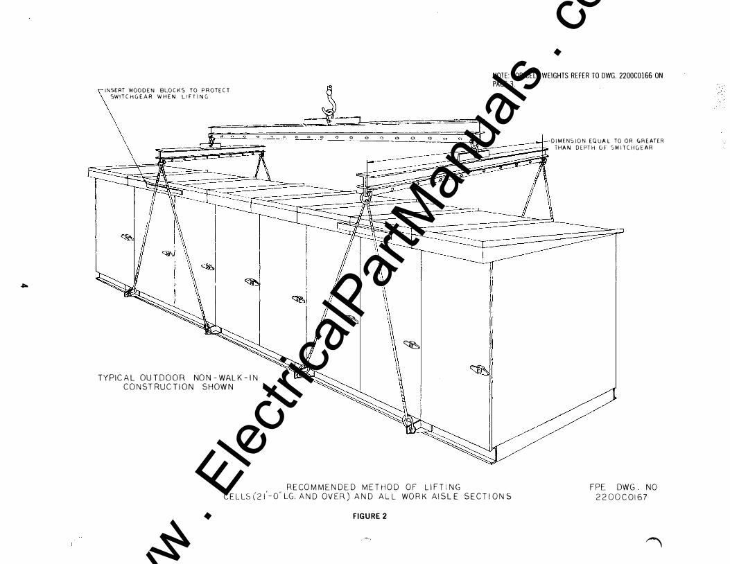
6. When lifting shipping units with a crane, it is p referable to use two hooks simultaneously, one on each end. Each pair of lifting hooks should be equipped with a spanner bar to prevent excessive distortion. If only a single hook crane is available,, arrange spanner(s) to lifting rig as shown on typical outdoor gear lifting drawings 2200CO I 66 and 2200CO I 67. ( Fig. I and 2)
7. Equipment can be rolled into place by applying pushing or pulling forces only to the steel base.
(
www . El
ectric
alPar
tMan
uals
. com

w
WEIGHTS OF CELL SECTIONS
DIMENSI ON EQUAL TO OR GREATER---J...----THAN DEPTH OF SWITCHGE:AR
RATING Of CELl
DST-2
DST-2
�KV-2C>O IeODA ·------- -----
'lKV-2:,0 2000A ----- · ----------
DS T-2 �KV-3':>0 DS T- 2 :, K v-::'"0 ----------DST-2 ':>KV-350 - -·---··----·
12UUA
L OUOA -lOOOA ----
ISKV-500 1200A
I_NsERT wooDEN sLocKs To Pnonu 1 _'5iJL.::-. -� j_Dc.r�---��.'K-.--=-sou c:0ooA
'oWITCIIGlAR Wllf:N LIFTING -, �� -- - - --- - iOOOA
1200A
I ��' L ·�·-- '"V ___ 2_()00A
3000A
WIDTH OF CELL
2&"
2o" -Zt" .::.t.." 36"
-�
APPRO:>-NET Wf:llHT
2,500 LBS 2,700 LB S
2,800 LBS 2,900 LBS 3,800 LBS -------· ·-
3���-LBS 3,30� LB '>__ 3,A(l() L BS
3,100 LBS
_ 3,400 L_�s 4,000 LBS
NOTE: APPROX. WEIGHT DOES NOT INCLUDE BREAKER.
TYPICAL OUTDOOR NON -WA L K -IN
CONSTRUCTION SHOWN
�
�
RECOMMENDED METHOD OF LIFTING CELLS(21'-0" LG. MAX) AND ALL WORK ;\ISLE SECTiONS
FIGURE 1
FPE DWG. NO
2200COI66
www . El
ectric
alPar
tMan
uals
. com
.....
NOTE: FOR CELL WEIGHTS REFER TO DWG. 2200C0166 ON
INSERT WOODEN BLOCKS TO PROTECT SWITCHGEAR WHEN Ll FT IN G
TYPICAL OUTDOOR NON-WALK-IN CONSTRUCTION SHOWN
a o o 0 o o o a o o
� \ ' �
PAGE 3.
�!
RECOMMENDED METHOD OF LIFTING CELLS(ZI
'-o"LG. AND OVEF�) AND ALL WORK AISLE SECTIONS
FIGURE 2
DIMENSION EQUAL TO OR GREATER THAN DEPTH OF SWITCHGEAR
FPE DWG. NO 2200COI67
�
www . El
ectric
alPar
tMan
uals
. com

U1
�
REMOVAI:ILE LIFTING PAD
TYPICAL INDOOR CONSTRL.CTION
�
�
ooo [] 0 0
�[] �
RECC MMENDE 0 ME Th:J D OF L1 FT I NG INDOOR CELLS
FIGURE 3
·'\
W EIGHTS OF CELL SECTIONS
WIDTH OF I APPROX. RATING OF C ELL I CELL NET WEIGHT
DST-2 5KV-250 1200A 2,500 L BS.
DST-2 5K V-250 2000A 2,700 LBS.
DST-2 5KV-350 1200A I 26" I 2,800 L8S.
DST-2 5K V-350 2000A 2,900 LB S.
OS T-2 5 KV-350 3000A 3,800 LB S.
DST-2 I�KV-500-JZQO-A 36'' 3 000 L BS. ------------ , I DST-2 15KV-500 2000A 36" 3, 3 00 LB S.
DSf::2jSj:_v:50Q 3000 A 36 '' 3,800 L B s: DST-2 ISKv-750 1200A 36" 3,100 L BS.
D ST-2 ISKV-750 2000A 3,400 LBS.
DST-2 15KV-750 3000A 4,000 LBS.
NOTE: APPROX. WEIGHT DOES NOT INCLUDE BREAKER.
FPE DWG. NO. 2 200C033S.
www . El
ectric
alPar
tMan
uals
. com

STORAGE BEFORE INSTALLATION
Protection against loss of equipment is an important precaution. Trouble and delay will be avoided by having good storage facilities arranged so that the apparatus will be accessible only to authorized persons and so that it can be quickly located when required in the erection program.
Switchgear equipment. regardless of whether it is to be installed immediately or stored for a while before being erected, should be kept in a dry. clean place. Conditions such as dampness caused by rain or change in temperature. cement dust, etc .. should be carefully guarded against. Covering the equipment with a temporary shelter or tarpaulin is frequently necessary both during storage and erection. The longer the period of storage. the greater must be the care taken for protection of the equipment. If dampness or c ondensatio n are encountered in the storage location, heaters should be placed inside the units to prevent moisture damage. Approximately 600 watts of heaters per unit will be required. Remove all cartons and other miscellaneous material packed inside the units before energizing any heaters. If the equipment has been subjected to moisture it should be tested with a IOOOV or 2500Y megger after heaters have been turned on for approximately one week. A reading of at least 100 megohms should be o btained.
Batteries should be uncrated and put on trickle charge immediately on receipt.
Relay covers should never be left off since the relays are delicate devices and future malfunctions because of moisture and dust could prevent proper tripping of circuit breakers.
HOL ES OR SLOTS PROVIDED IN SWITCHGEAR BASE FOR WELDI N G (PREFERRED) OR BOLTING. SUGGEST 3/8" H ARDWARE. SEE FLOOR PLAN FOP- LOC AT 10 N.
Breakers should be prepared for storage separately. Refer to appropriate breaker instruction book.
FOUNDATION Federal Pacific Metal-Clad Switchgear is accurately built on true and level bedplates. This care and accuracy insures ease of operation and interchangeability. Equal care during installation should be used. True and level supports for this equipment are of utmost importance. Little more than ordinary care in laying out and preparing the foundation will be repaid in reduction of cost and labor of installation. The steel supporting members used in the tloor should be held level until the concrete is set. The surface of the tloor under the housing should not project above the supporting members. For indoor switchgear only. the surface of the tloor should not lie below the supporting members by more than Yx". *Theflvvr infrvnt v{the housing should not vary more than 1/8" in any square mrd and must not project above the level of the supporting members. A smooth floor will make rolling of the removable element eas1er.
*When installing switchgear where floors already exist, it will usually he desirable to pour a new finished floor above with embedded rhannels or rut slots for embedding and leveling the supporting ,·hannels.
Encircling loops of reinforcing or building steel around single phase conductors should be avoided in the main cable entrance area if these are rated 600 amperes or above.
FIG. 4 or an equivalent must be used to obtain an adequate foundation. Bolting the switchgear to the foundation is an acceptable method. Welding to the foundation is preferred because it does not require an accurate lining up of holes.
FIG. 5 or an equivalent must be used to obtain an adequate foundation for outdoor equipment. Welding to the foundation is the preferred method of securing. *For indoor switchgear only.
SWITCHGEAR BASE
WELD HERE
<1 0 <J
RGURE 4 RGURE 5
6
(
www . El
ectric
alPar
tMan
uals
. com

( PART II - INSTALLATION HOUSING INSPECTION
I. Before setting equipment in place, refer to switchgear drawings and, after completely uncrating equipment, check permanent location to see that equipment will properly fit on channels and foundation location. Align and bolt all shipping sections together so that a continuous switchgear installation is obtained. ( Refer to Assemblies "A", "8". and "C' below.)
2. Carefully inspect all portions of the circuit breakers for possible damage. 5kV 250 \!VA circuit breakers are shipped completely assembled with arc chutes. l5k V and 5k V 350 \1 V :\ circuit breakers are shipped separate from arc chutes and may be assembled properly in the protected work aisle and center aisle outdoor houses by use of the arc chute lifting bracket attached to the aisle ceiling. After inspection, the circuit breakers should be carefully inserted and racked into the switchgear cells.
3. Remove shipping braces. inspect for damaged parts, cracked epoxy bus, primary disconnect bushings, bent secondary disconnects. cracked porcelain insulators, wiring insulation - check and report evidence of abuse to equipment.
4. Inspect cells to be certain that •power·contacts and secondary disconnect contacts located in rear of cell are free of dirt and dust. Cell floor must be clear of all dust and debris to facilitate easy handling of circuit breaker.
5. The breaker is provided with a maintenance closing device for manually closing the breaker. It cannot be used as a manual device to close in the breaker when in the cell. This handle should be used only when the breaker is withdrawn from the compartment.
6. Refer to the circuit break er Instruction Manual I \1-820.11 before mserting breakers into cells.
7. If porcelain entrance or load bushings are mounted in the roof. use flexible connections from incoming and outgoing lines to reduce the strain on the porcelains.
8. Inspect all instrument doors for damage to protective relays.
Control-wiring underground conduit from the control building should terminate inside the switchgear at a level above any existing high-water marks ( 4" maximum above floor line).
Heaters are furnished in front and rear of each outdoor unit.
The following descriptions and drawings give the general arrangement, sequence of installation, method of fastening the gear to the foundation. location of conduit areas, and other information for the proper location and assembly of the
' equipment:
ASSEMBLY "A": OUTDOOR PROTECTED WORK AISLE CONSTRUCTION (See dwg. 2200D0/�9.)
7
I . Locate the cell sections accurately on the foundation. When cell equipment is in two sections, locate the sections from the center of the foundation.
2. Check the leveling of the units; use shims where foundation is uneven. Remove lifting lugs.
3. When cells are in two sections and the above are properly leveled and aligned, firmly bolt the bases, cells, and roofs together with the hardware furnished for this purpose.
4. Aisle Section: A. When aisle section is in one piece, remove all
protective lumber and bracing except wooden horizontal and center vertical braces. Remove lifting lugs.
8. When aisle section is in two pieces, remove all protective lumber and bracing from each section except wooden horizontal brace, wooden vertical corner and vertical center brace, and open end wooden frame bracing. Remove lifting lugs.
WARNING: U�DER \10 CONDITION MAY THE WOODE� HORIZONTAL ROOF SUPPORT BE REMOVED BEFORE ITEM 5 BELOW IS COMPLETED.
5. Slide aisle section(s) into place, making sure that aisle roofs overlap cells and rest on top of cell roofs. Aisle s ide sheets must be on outside of cell sect ions.
6. When aisle section is aligned with the cell portion, apply caulk (furnished) between overlapping roof and side sheet surfaces. Firmly bolt bases, roof, and side sheets together and apply cement ( furnished) to roof gasket joints.
7. Remove existing wooden braces.
8. Remove floor plates at ends and at base anchoring points.
9. Fasten aisle base to cell base. (See dwg. 2200C0171, Figure 1 1).
10. Tackweld or anchor the bases to the foundation as indicated on the floor plan drawing.
II. Re-install floor plates.
12. Check and adjust instrument doors for proper alignment to correct possible mishandling during shipment.
13. Assembly of main bus between shipping splits ( Refer to Fig. 6) A. Measurements must be taken between phase to
phase before installation of main bus to insure that the dimensions shown on Table "A" are kept.
In the event the necessary dimensions are not available, loosen the riser and main bus connection in the adjacent cells and adjust until the required clearances are obtained. www .
Elec
tricalP
artM
anua
ls . c
om

B. Yell ow grommets must be prope�ly p ositioned in the porcelain (lSKV) or glastlc (SKY) bus support prior to inst�llin� the bus. Th� grommet p osition must be mamtamed securely m the bus support when the bus is fed through.
C. Bus Assembly a. Remove splice plates b. Install main bus through bus support c. Re-assemble splice plates d. Torque all shipping break splices per recom
mended torque in Table B, page 8. Assemble the PVC boots around the main bus joints and fasten together with nylon hardware furnished (see instruction Fig. 13, page 14).
14. Re-connect wiring at shipping breaks and where required per wiring diagrams furnished.
NOTE:
A. Customer control wmng connections must be terminated at terminal blocks only - no splicing is permitted.
B. All wiring in conduits must be in accordance with National Electrical C ode.
ASSEMBLY "8": OUTDOOR CENTER AISLE CONSTRUCTION
I . Complete items I , 2, 3, 10, 12, 13, and 14 per assembly "A" above.
2. Bolt aisle-end channels in p lace.
3. Install floor plates.
4. Assemble end panels of the aisle section.
5. Assemble aisle roofs, seam gaskets, and p rotective cover.
6. Apply caulk (furnished) between overlapping roof and side sheet surfaces. Firmly bolt roofs and side sheets together and apply cement to roof gasket joints.
7. Check and adjust instrument doors for proper alignment to correct p ossible mishandling d uring shipment.
ASSEMBLY "C": OUTDOOR N ON-WALK-IN CONSTRUCTION
I . Complete items I . 2, 3, 10, 12, 13 and 14 per assembly "A" above.
TIGHTENING CONNECTIONS
I. Bus splices at shipping break should be carefully inspected to be certain that good clean, uncontaminated contact is obtained before bolting up tight. A torque wrench should be used, to apply torque as recommended in Table B.
2. It is also important to be sure that all outgoing cable connections are tightened in the same manner as bus splices.
8
-.::::: SHIPPING SPLIT
t "I G --------·�
IF=fc�' '---. �GeOMM,-
1 I I I¥ BUS SUPPORT =
I I
I f.-- F-----{ � ·I I· E
i-D�D--.
CELL B CELL A WIDTH WIDTH
TABLE "A" (DIMENSIONS IN INCHE S)
A B c
36 36 10 26 26 7 36 26 10 26 36 7
D E F G
10 36 36 36 7 24 26 26 7 34 31 28
10 28 31 34 FIGURE 6 SHIPPING SPLIT
TABLE B
NOTE
All dimensions shown from <t_ to <t_ of bus risers
RECOMMENDED TORQUE (Values in Foot Pc1unds)
Type Bolt Steel* E11erdur
5/16"-18 18 15 3/8"-16 31 21 1/2"-13 55 45 5/8"-11 80 65
'Steel hardware must be SAE 5 or stronger.
BUS DUCT FIGURE 7
Bus du�t connecting between groups of metal-clad switchgear or between metalclad switchgear and other apparatus, should be installed as shown on the arrangement drawings furnished with the duct. Supports should be provided as indicated on the drawings.
All joints in the bus should be assembled and insulated as previously described for main buses. Adjustable joints are provided to allow for variations in building construction, etc. These joints should be loosened before installation of the duct, then tightened after being set in the position required by the fixed points at the ends of the duct.
Outdoor bus duct must be gasketed at the joints between shipping sections.
All removable covers on outdoor bus duct except bottom covers must be gasketed. Do not bolt covers in place until all interior assembly work on the duct is completed and access will no longer be required.
Outdoor bus duct is provided with heaters. Connect these heaters in accordance with the wiring diagrams furnished with the equipment before energizing the bus duct.
ADDITION OF UNITS TO EXISTING EQUIPMENT Before adding units to existing equipment, consult and study all drawings furnished with the equipment. In addition to the usual drawings furnished with new equipment, special drawings may be furnished covering complicated or special assembly work. Also, check to make sure all necessary parts are on hand.
(
www . El
ectric
alPar
tMan
uals
. com

c.o
CONDUIT
SPECIAL CANTILEVER MOUNTING
NOTE: FOR SH IPP ING SECTIONS AND SPECIAL MOUNTING DIMENSIONS S E E JOB DWGS AND FLOOR P LA N
FRONT PANEL
AISLE BASE
REAR DOOR
LEVELING CHANNEL OR "I" BEAM
AISLE FLOOR
0
CONCRETE CURBS OR PADS
0
INSTRUMENT DOOR
0
r-CONTROL CONDUIT ----._ AREA':>
ISKVf- -i SKV
NON -WALK-IN
BOLTING,A I':>LE TO AISLE ��1��.� '-BOLTING,ClLL TO AND CELL TO CELL �'J� AISLE CHANNEL
�
REAR DOOR
I• •II POWER CONDUIT ARE A
REAR DOOR
CELL BASE
DEPTH OF AISLE tXTENSION __ __jL DEPTH OF SWI TCHGEAR -------1 PROTECTED WORK AISLE
REAR DOOR� 1['-� . ][�_=-: ' " " " " "'
000' ···. - I VREAR DOOR
Jl 0 � "
•
II 1L � M I-----DEPTH OF SWITCHGEAR
II j--]!; � . .
0 � 0 0
\AISLE BASE CHANNEL SUPPORT
0 I: ___ � ! , ___ Jl � ��..;u
4' • . 4 :O.·
0 ll -� II' .
.
CENTER AISLE AREA -----+-----DEPTH OF SWITCH GEAR -------'-i CENTER AISLE
METHOD OF MOUNTING AND INSTALLATION
OF BASES FOR OUTDOOR HOUSES
FIGURE 8
FPE OWG. NO.
2200COI68
www . El
ectric
alPar
tMan
uals
. com

-C)
IMPORTANT NOTE:
NOTE I: ONE PIECE A ISLE S HIPPING SECTIQt-J_ DO NOT REMOVE WOODEN HORIZONTAL i'ND Ct_NTER VrRTICAL ROOF BRACES UNTIL AISLE ROO!' OVrRLAP:- AND m·srs ON SW ITCHGEAR ROOF
NOTE 2: SPLIT AISLE SHIPPING SECTION
DO NOT REMOVE WOODEN H OR IZONTAl ,VFRIICAl C:URNI::R AND VE RTICAL C EN TE R BRACES, AND OPEN END WOODEN FRAME BRACING UNTIL A ISLE ROOF OVERLAPS AND RESTS ON SWITCHGEAR ROOF
WOODEN �-, HORIZONTAL ; ""- "-ROOF BRACE� l
WOODEN VERTICAL BRACE�
[Jj �ft6·lS X l.l'!>LL,BOLT
AISLE ��
SECTION
�� ------':' -----"- ',
l/8··•& c;,tu o (JN UNO I:. "'':.101:.
/ // _/�
-----�_.--/
-----
-----/'---��/------
�-
'I""- - , / ........ ,,, �'� . /�/
-- - _____ ,/ ----
-� �/B-16X I�L<>. C.A.RRIAC.E BOLT --_....__
/r:<:--._'--._ -;- "--- -, '-, ', --"-.._ ' ,' , ' �/ ', '"---._ �- --- '-...., ----><--=-
./ ........ �' '·,··-, -, Ell- !\' '-� -t'l - "l 1\t-
�'- Jjl I Jlt /
COVER PLATE _7/
545180061J RI GHT HAND 54S28006e LU'T HA ND (SHOWN)
FIGURE 9
c=-. l�r-:�=:'"" 1 d
IIOII::APPLY CAULKING COMPOUND TO ALL BUTTING AND OVERLAPPING JOINTS
PROTlCT IVl CO-lER
SWIT(HGEA.� P.OOF
\PPcY CEMENT
ROOF GASJ<ET 7 - =_ �- - -J----Tr'YP
AISl� _/ ROot
--SWITCHGEAR SECTION
tA";:�;NG _/ CO�POUND L3;b+l� NUT WITH LUCK ANO f lATW.A.,HER
ROOF ASSEMBLY
PROTECTED WORK AISLE
METHOD OF JOINING A I SLE AND SWITCHGEAR SEL liONS AT INSTALLA TION
220000169
-·'\
www . El
ectric
alPar
tMan
uals
. com

.... ....
APPtr CEMENTM . -- /· ROCJF C.ASKEr�. .311• It> :..Tu[J-\
��=�=� - - �1 lJN u'OlRS<ut �-�--�___-r---�' AISLE ROOf-'/-· APPlY \:-�WiflHvtAH RUU�
CAUL KIN(., t's·IG NUT WlfH LOCK
-�--=-�--
Ro0uFMPAS�EMBLY AND fL Ar ........ .,HI H
OUTOOOH ROOF GA5KE. T
Al)ll:. 1-<0uF
UPPI:� ':>IDE. ':>HI:.U (AISl £)-
���-�=.:::�� AI':>L£ DOOR F f -I.A�E f•'oS� MBLY
��Ib-IS X !.2� LC. BOLT
.-- --:;;; -��____..:..-.J / f'B-IbX t•LG. ' ,, '" -.
"-�:"·�� I === I
-
·. ""- ..,_ /-'\CARRIAGE BOLT
�
:11m ====== I ........-------- AI':>Lf lXHNO:.ION !'... r--- 51 DE 'SHEET �"'J
I \
� \ !
'" <' ' ,, " ,, " '' --- �""'
�----�--------________.).''
�---------------'
SWITCHGEAR SECTION
...
I I I I I
AI'LE DOOR----
. I ill� n I -----111lf I
3/8-JbX I.�OLC..BOLT
I I 1�11 ===== rllr ===
- - - --1 I _b��-= J" __ .'.-;c--�-
1 ' •
'
�����:::L�'i=� 'j
AI':>LE BASE CHANNEL SUPPORT
CENTER AISLE _ SEI:;_!I_Q_ti_
CFNTER WORK AISLE
METHOD UF JOINING AISLE AND SWITCHGFI'\n
Sr(TIONS AT INSTALLATION
220000170
FIGURE 10
�
-�
------\
. �_:_::::.-=� @ � 0 �
�
SWI TCfiGE AR SECTION
www . El
ectric
alPar
tMan
uals
. com

r � -lb HEX NUT (WELOEO)
r===�����==9
AISLE BASE T O CELL BASE
::O=lCT>:CTED WO"<K AiSLE
%-16 X (LG. HEX HO. BOLT
LOCK & FLAT WASH£ R
AISLE ,::r-AN."lEL SUPPCRT
r� -lo HEX �UT \ NELOED)
CELL BASE
AISLE CHANNEL SL.:PPGRT TO CELL BASE
CE\lTER WORK A:SLE
EXtSTtNC, ROOF FUTURE ROOF
I
CELL BASE
/�k-20X.75LG,HEX HO.BOLT LOCKWASHER &. HEX NUT
I
CELL UPRIGHTS
REAR FRAME UPRIGHTS
---jf!§�l1''-----lL_ ]._ -18 X .75 LG. CARRIAGE BOLT IE) LOCK'�ASHER, FLt..TW.A.SHER .l.ND
SECTION A-A (TOP SECTION) HEX NUT
CELL TO CELL CREA?J
CUT TO SUIT AT ASSEMBLY
PROTECTIVE COVER
ROOF FLANGES
1% -IBX I.ZS LG."EX HD. BOLT LOCKJ..ASHER,t"LAT WASMERS AN 0 HEX NUT
BOLT'NG DETAILS ZZOOCOI?I
FIGURE 11
PROTECTIVE COVER
SIDE SrH.ETS,PA"'ELS,ANO DOOR MOVED, CAULKED .\"oO BOL TEO
1 IN END POSiTION I
\ROOF END TRIM ('.IGVE� &. 60L ��:; -o END POSITION)
I
� '
,,1, .... EJJ CONOUI-1' �s�nH
\ i{
''-+-----'-----__,j I i +II I
I' k . .
I I I I :: t : :J I -.---1c - 1 --- -� --- --�
EXISTING UNITS ------i--FUTlJRE UNITS-�
FIELJ PROCEDURE "OR EYr'-'lSIOfl OF EXIS-:-ING GUTDOC)R �WITC- H GtAR
FIGURE 12
12
220000172
www . El
ectric
alPar
tMan
uals
. com
(
BEFORE ANY COVERS ARE REMOVED OR ANY DOORS OPENED WHICH PERMIT ACCESS TO THE PRIMARY CIRCUITS, IT IS ESSENTIAL THAT THE CIRCUIT OR CIRCUITS BE DE-ENERGIZED AND BREAKERS BE WITHDRAWN TO A DISCONNECTED POSITION AND TAGGED.
IF WORK IS TO BE DONE ON REMOTE EQUIPMENT CONNECTED TO A UNIT THE BREAKER FOR THAT UNIT SHOULD BE PLACED IN THE DISCON:\fECTED POSITION AND TAGGED. ALSO THE REMOTE EQUIPMENT SHOULD BE ISOLATED FROM ANY OTHER POWER SOURCES CONNECTED TO IT.
Dwg. :'1/o. 2200COI72 (Figure 12) indicates the special procedures required to add new metal-clad units to outdoor equipment with protected aisle. For indoor equipment it is usually necessary only to remove the end cover sheets and to re-assemble them on the new units after these are located and bolted to the existing units. Otherwise, the installation procedure is the same as described in Part II.
When the units are in place and mechanical assembly is completed, assemble the main bus and other primary connections. Secondary wiring and control bus connections should be made in accordance with the wiring diagrams furnished with the equipment.
EQUIPMENT BATTERIES
Follow battery manufacturer's instructions carefully when installing the battery. Be sure that ventilation is provided to carry off the fumes. If steel work seems to be affected by the fumes, apply black asphaltum paint.
Make sure that the battery charger is functioning, and that the charging rate is not excessive. Test for specific gravity regularly.
If battery is installed remote from the switchgear, have cables of sufficient size to keep the voltage drop at a minimUm.
Be sure battery is charged and no abnormal loads are evident before putting switchgear in service.
WIRING
All incoming and outgoing control connections should be made in accordance with the switchgear schematic and wiring diagrams. After wiring is completed, all connections should be carefully checked against the diagrams to insure that all connections are correct and proper.
The wiring diagram number of each switchgear unit is stamped on the nameplate of the control panel. The wiring diagram number applying to each circuit breaker is stamped on each breaker on the nameplate.
Interconnecting wiring diagrams between the associated equipment are not normally supplied with metalclad switchgear.
GROUNDING
Each switchgear assembly is provided with a ground bus extending the full length of the complete assembly.
13
Sections of ground bus previously disconnected at shipping breaks must be reconnected when the units are installed. For recommended bolt torque see Table B.
The ground bus should be connected to the station ground at both ends with as direct a connection as possible and should not be run in metal conduit. The grounding conductor should be capable of carrying the maximum line-to-ground current for the duration of the fault.
When switchgear has center aisle construction, insure that the connecting ground bus is connected between opposite aisle sections.
A reliable permanent and low resistance ground connection is necessary for every switchgear installation. A poor ground may be worse than no ground since It gives a false feeling of safety to those working around the equipment. It should also be of sufficient capacity to handle any abnormal condition that might occur on the system and should be independent of the grounds used for any other apparatus.
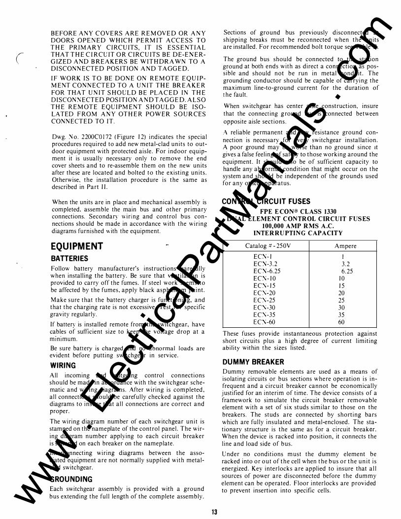
CONTROL CIRCUIT FUSES
FPE E CON® CLASS 1330 DUAL ELEMENT CONTROL CIRCUIT FUSES
100,000 AMP RMS A.C. INTE R RUPTING CAPACITY
Catalog It - 250V Ampere
EC:\f-1 I EC:\f-3.2 3.2 EC\'-6.25 6.25 EC\'-10 10 EC:\-15 15 EC\"-20 20 EC\"-25 25 EC\"-30 30 EC\"-35 35 EC\"-60 60
These fuses provide instantaneous protection against short circuits plus a high degree of current limiting ability within the sizes listed.
DUMMY BREAKER
Dummy removable elements are used as a means of isolating circuits or bus sections where operation is infrequent and a circuit breaker cannot be economically justified for an interim of time. The device consists of a framework to simulate the circuit breaker removable element with a set of six studs similar to those on the breakers. The studs are connected by shorting bars which are fully insulated and metal-enclosed. The stationary structure is the same as for a circuit breaker. When the device is racked into position, it connects the line and load side of bus.
Under no conditions must the dummy element be racked into or out of the cell when the bus or the unit is energized. Key interlocks are applied to insure that all sources of power are disconnected before the dummy element can be operated. Floor interlocks are provided to prevent insertion into specific cells. www .
Elec
tricalP
artM
anua
ls . c
om

INSULATION BOOTS ON 5 AND 15KV CLASS EQUI PMENT,BUS B AR JOINTS ARE INSULATED WITH MOLDED B US BAR BOOTS. THE BOOT IS PULLED IN PLACE AROUND THE BUS 13AR JOINT. AFTER FITTING, HOLES ARE PUNCHED FOR CLEARANC E OF THE N YLON HARDWARE,
NOTE: CHECK BUS BOLT TORQUE BEFORE ASSEM BLING BOOTS.
TAP
( (
�
r 0 If: 0
�
NOTE ''A"
MAIN
_ £ NOTE 'A�- - ---,
?
---� MAIN � l=-�-':_! : THRU i : II !! II] l L __ r-_j L __ -;r-
L BOOT L BOOT ,, T ,, RIGHT ANGLE THRU
NOTE.''A": PUNCH 9/32 DIA. HOLES AND ATTACH WITH NYLON HARDWARE.
FIGURE 13
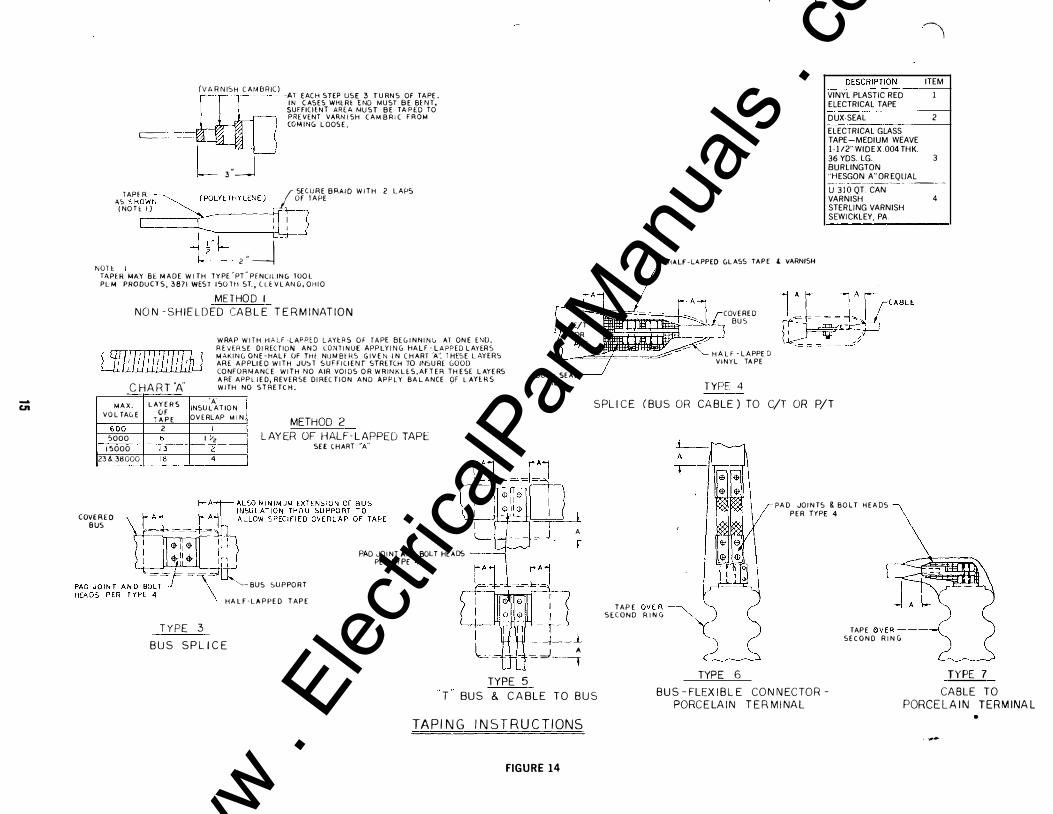
TAPED CONNECTIONS For taped connections use materials as listed in taping instructions, Fig. 14. Extreme care should be taken in taping unusual contour joints with vinyl tape.
Taping a flat or a cylindrical surface such as a bus bar or cable is a relatively simple process in which much the same technique is used whether the tape is paper, cloth, or plastic. Vinyl tape may be stretched slightly to help it conform to irregular contours. This is an advantage if properly understood and used correctly, but can be harmful if the tape is stretched unnecessarily to make it "conform." The pressure sensitive adhesive is not designed to withstand large sidewise (shear) forces for a long time; and if the contour is such that the tape tension can be relaxed by a side slippage, some slippage will take place.
GROUND FAULT CURRENT TRANSFORMERS (THROUGH-TYPE)
Through-type current transformers are furnished where specified for sensitive protection against ground
14
faults. These transformers are normally installed in a horizontal position directly above or below the primary cable terminals, so that the primary cable or cables can pass through them. One transformer is required for each three-phase circuit.
Where armored cable is used, the armor must be terminated and grounded before the cable passes through the transformer. Armor clamps are furnished for this purpose when specified.
When lead or other conducting sheath cable, or cable with shielding tape or braid is used, it is recommended that the sheath or shield be grounded solidly to the switchgear ground bus. The ground lead should be bonded to the sheath or shield on the side of the current transformer away from the primary terminals. In cases where the ground cannot be applied before the cable passes through the transformer, bond the lead to the sheath or shield between the transformer and the primary terminals. The ground conductor must then be passed back along the side path through the current transformer before being connected to the ground bus.
Where potheads are used in units provided with ground fault current transformers, the pothead mountings must be insulated from ground. www .
Elec
tricalP
artM
anua
ls . c
om
-Ul
(VARNISH CAMBRIC) =�#fu- -AT EACH STEP USE 3 TURNS OF TAPE. IN CASES WHlRl END MUST BE BlNT, SUFFICIENT AREA MUST BE TAPED TO PRE VENT VARNISH CAMBRIC FROM COMING LOOSE.
c:=-::
L 3._j TAPf R f SECURE BRAID WITH
AS �HOW--;--'2?tLYlTHYLENE) OF TAPE (NOHI)
[[J I : : -0�� z"_j
2 LAPS
N?��ER1MAY BE MADE WITH TYPE"PT"PfNUI.ING TOOL PLM PRODUCTS, 3871 WEST !50TH ST.,lLEVLAND,OHIO
METHOD I NON -SHIELDED CABL E TERM INATION
[j[[/f!J!l/1!1!/f] WRAP WITH HALF-LAPPED LAYeRS OF TAPE BEGINNING AT ONE ENIJ. REVERSE DIRECTION ANJ CO.�TtNUE APPLYING HAL F-LAPPED LAYERS MAKING ONE-HALf OF THl NUMBlRS GIVEN I N CHART 'A". T HESE LAYERS ARE APPLIED WITH JU�T SUFFICIENT STRETCH TO IN�URE GOOD CONFORMANCE WI TH NO AIR VOIDS OR WRINKLES,AFTER THESE LAYERS ARE APPLIED, REVERSE DIRECTION AND APPLY BALANCE OF LAHRS WITH NO STRETCH. CHART 'A'
MAX. VOLTAGE
�00 5000 15000 23&. 38000 L_
COVERED BUS
LAYERS 'A' INSULATION OF OVERLAP MIN, -rA PE
2 I METHOD 2
b I �z 13 2
LAYER OF HALF-L APPED TAPE SEE CHART "A"
18 4
PAD JOINT AND SOL T HEADS -PER TYPE 4
'�-BUS SUPPOR T
HALF-LAPPED TAPE
TYPE 3 BUS SPLICE
-J TYPE 5
-----�
ITEM
VINYL PLASTIC RED l ELECTRICAL TAPE
DUX-SEAL 2
ELECTRICAL GLASS TAPE-MEDIUM WEAVE l-l/2''WIDE X.004 THK. 36 YDS. LG. 3 BURLINGTON "HESGON A'' OR EQUAL --- - ----------- --------U 310 QT. CAN VARNISH 4 STERLING VARNISH SEWICKLEY, PA
1- HALF-LAPPED GLASS TAPE l VARNISH
J:l � �� covERED �:CJii"'" �RT !!11!\ I � BUS
DUX- SEAL FILL
H A L F -LAPPE D VINYL TA PE
TYPE 4
� -=== = - = ::::.,...-
SPLICE (BUS OR CABLE) TO C/T OR P/T
A
=�---�
TAPE OVER� y " " " '
"" ' �-
TYPE 6
PAD JOINTS & BOLT HEADS PER TYPE 4
TAPE OVER ----( SECOND R ING
TYPE 7 T BUS & CABLE TO BUS BUS -FLEXIBLE CONNECTOR
PORCELAIN TERMINAL CABLE TO
PORCELAIN TERMINAL TAPING INSTRUCTIONS •
. ..,.,..
FIGURE 14
www . El
ectric
alPar
tMan
uals
. com

PART Ill - PRE-ENERGIZATION TESTS PREPARATION
BEFORE STARTIN G ANY INSPECTION OR TESTI�G BE SU RE PRIMARY CIRCUITS ARE D EENERGIZED.
Careful reference should be made to each component instruction leaflet before attempting to place the switchgear in service. If d ry-type or oil askarel-filled power transformers are furnished as part of the switchgear equipment, consult their instruction books or leaflets, particularly regarding absorption of moisture, and effects of dust and sand. etc.
The e4uipment should be checked to be certain no tools or any other equipment have been left in th� switchgear. When connections are to be made to or from an electric utility, public or privately-owned, consult their representatives very early in the construction period, as manv of them have very strict requirements which must be �et before service connections will be made.
Anv indication of moisture will require that equipment be dried out before p lacing in service. Care should be exercised in d rying-out operations to be certain that the maximum temperature during the drying period does not exceed 70 to 75u C. on switchgear. In the event it is desired to give the equipment a high potential test before placing in service. this test should only be made after the equipment is thoroughly dry. The value of test voltage should correspond to the voltages listed in Table C. Note that field tests are 75% of the factory test values.
DIELECTRIC TESTS
Dielectric tests are made at the factory to determine the adequacy of insulation. Devices used as part of switchgear assemblies shall be capable of meeting these tests.
Exception-There are certain apparatus such as potential transformers, auto transformers, motor starting reactors, and motor-operated devices whose standards call for a lower test v oltage than those given in Table C. When such devices are used, they must be disconnected during these tests.
Alternating-current test voltage shall have a crest value equal to 1.41 times the values specified. A sine wave shape is recommended. The frequency shall not be less than the rated frequency of the apparatus tested . The test voltage shall be applied for one minute.
Direct-current test v oltage, if used in lieu of alternatingcurrent test voltage, shall be 1.41 times the specified alternating-current voltage.
OPERATIONAL TESTS U pon completion of installation, and inspection of the circuit breakers and other components, together with installation of any incoming and outgoing control connections, it is time to start operational testing. Outgoing feeder cables should not be connected at start of test.
16
Rated Voltage
600 v 4.16 kY 7.2 kY
13.8 kY 23 kY 34.5 kY
TABLE C DIELECTRIC TEST VALUES
Standard 60 Cycle 60 Cycle Full-Wave
KV KV Impulse Field Test Factory Test (Withstand)
Tests KV
1.6 2.2 NA 14.25 19 60 27.0 36 95 27.0 36 95 45.0 60 150 60.0 80 150
FIGURE 15
When the switchgear has electrically operated circuit breakers. they are operated in some installations from local battery or auxiliary control supply, and in other installations are operated from the switchgear bus, or a connection ahead of the incoming master circuit breaker. In the event the primary source of power is locked open, it will be necessary to use an auxiliary source of power to operate the circuit breakers, lamps, bell-alarm switch, undervo ltage devices, rectifiers, capacitor shunt trips, etc. Check circuit breakers in "test" and "operate" positions, paying particular attention to good contact between movable stationary secondary contacts in both positions. Check puffer by placing hand over arc chute and feeling puff of air during opening operation. Check that primary disconnect penetration is at least Yx" on cell stabs. Check that breaker mechanism closing springs discharge between "test" and "removed" positions. Key interlocks should be o perated manually to make sure that p rotection is complete. Remove spare keys to supervisory office.
Each relay and trip device or other component should be operated manually to be certain its contacts perform their required function. Remove any material that was installed at the factory to block parts or devices during shipment. Preliminary settings for test purposes should be applied to relays. The various operational functions are indicated on the schematics and wiring diagrams o f the switchgear equipment.
After completion of all operation tests, all relays should be set according to specified requirements. If a coordination study has been made this study should be referred to for the settings. Check that the primary device settings are accepted by the Power Company if required. All trip indicators on the relays should be checked to see that they function p roperly.
U pon completion of device settings and test, the main incoming and feeder cables should be properly phased out and connected to the switchgear. Incoming and outgoing cables should be braced so as to take mechanical strain off studs of circuit breakers and ·porcelain supports of various types. Clean · out construction materials, d irt, nests, etc. www .
Elec
tricalP
artM
anua
ls . c
om
Inspect for damaged parts, cracked epoxy b us, primary disconnect bushings, bent secondary disconnects, cracked porcelain insulators, wiring insulation - check and report evidence of abuse to equipment.
The entire switchgear structure and all b us duct should be carefully vacuum cleaned (preferred) or b lown out, and all rear and side plates that have been removed should be rebolted in place. All secondary and power connections should be tested for grounds with high potential tester or megger. Megger readings of one megohm per thousand volts are acceptable. If readings are lower, equipment should be dried out until insulat ion resistance values improve to one megohm per t housand volts.
Preferable readings are:
Operating voltage K V . . 1 .2 2.5 5.0 8.66 1 5 23 38 Insulat ion Resistance . . . 1 2 25 50 I 00 1 50 250 400
Megohm at 25° C.
PART IV - MAINTENANCE The following preventive maintenance program is outlined for medium and high voltage metal-clad switchgear with air-magnetic or low oil content type power circuit breakers. Should the need occur, the Field Service Department of the Power Equipment Systems Division of Federal Pacific Electric Company is equipped to assist you with any maintenance or repair which may be required t hroughout the anticipated long life of this equipment.
FPE "On-Site Test Facili ties" are available to you. This service includes engineering inspection and testing of electrical equipment planned to supplement your regular maintenance program, to improve equipment reliability and to protect your inves.tment.
MAINTENANCE BENEFITS AND FACILITIES
Basic elements are outlined for a maintenance program of switchgear installations.
A. MAINTENA�CE PROGRAM A well executed program has these benefits:
I . Longer life of switchgear. and fewer replacements.
2. Reduced time on repairs and overhauls, and the opt ion of scheduling them at an opportune t ime.
3. Fewer failures with unexpected outages.
4. Timely detection of any undesirable operating conditions which require correction.
5. Improved plant performance and increased operating economies.
B. MAINTENANCE RECORDS A fi le should be established and include:
I . A record of all installed switchgear and its mamtenance schedule.
17
Check proper operat ion of doors, transfer trucks, latches, filter units, lighting, hinges, key interlocks (keys and function), gaskets and seals.
On protected work aisle and center aisle O.D. hq.use check that contractor properly assembled and caulked the shipping breaks, and aisle split . Check undercoating, foundation, and for rodent holes.
Check phasing connections of buses (especially at t ransition points) and connections to transformers and bus ducts. Capacitor trip device - check operation and check that it will h old charge at least 5 minutes by de-energizing primary power as checking operation 5 minutes later. Spot check secondary voltages to make sure proper connections and proper transformer ratios have been selected. Overvoltage can cause premature burnouts of indicating lights. Check lamp burnouts.
Check that C. T. secondaries are not open circuits, especially if going off the board to a remote l ocation. Check that zero seq. C. T.'s have been properly connected and t hat cable has been properly grounded.
2. Nameplate data of the equipment and its major components, instruction books, renewal parts bulletins and drawings.
3 . A list of all items which have to be inspected and what adjustments are to be checked.
4. A record of past inspections and test results.
C. MAINTENANCE TESTS Maintenance tests are applicable as indicated:
I . Insulation resistance tests of the breakers and of the switchgear bus can be useful in determining the condition of the insulation if they are made regularly. Since definite l imits cannot be given for satisfactory insulation resistance, a record must be kept of the readings and com parisons made. Deterioration of insulation and the need for corrective action can be recognized if the instrument readings are progressively lower after each test.
2. High potential tests are not required and are not recommended except in special circumtances, such as after repairs or modifications to the equipment that included the primary circuit. When such tests are necessary, they may be made using 75% of the standard 60-cycle insulation test voltage for new equipment at t he factory. See table C, page 1 6.
3. After the switchgear has been serviced and adj usted, i ts operation should be checked before i t is returned to service. This can be best done by putt ing the breaker in the test position and operating i t with i ts associated control and protective devices. If it is desired to test t he b reaker outside its compartment, use the test-jumper supplied with the switchgear. www .
Elec
tricalP
artM
anua
ls . c
om

D. M A I N T E N AN C E E Q U I P M E N T A dequate maintenance equipme nt should include:
I . Spare parts for at least those parts of the switchgear that a re vital to continued operation. Manufacturer's recommended list of spare parts can be used as a guide in c ombination with o perati ng experience to determine variety a nd q uantity of parts to be stocked.
2 . A well-lighted shop equipped with the following:
a . A test cabinet for air magnetic b reakers or an inspection rack.
b. Maintenance closing device for power b reakers.
c. Test j um per for co nnecting breaker to control circuit w hen it is outside its compartment.
d . R elay test p lugs for making tripping, timing and calibration tests of relays.
e. A selection of ammeters, voltmeters and instrument transformers.
f. An insulation resistance tester.
g. A n overhead c rane o r hydraulic lifting device.
FREQU ENCY OF INSPECTIONS It is generally good practice to inspect equipment three to six months after it is first p ut in service and then ins pect and maintain it every one t o t hree years depending on its service and o perations conditions. This suggested schedule is only a guide. Cond itions that can m ake m ore frequent maintenance necessary are:
I. H igh h umidity and ambient temperature.
2. Corrosive atmosphere.
3. Excessive dust and dirt .
4. H ig h repetit ive duty.
5. Frequent i nterruption of faults.
6. Older equipment.
7. H istory on preceding inspections.
MAINTENANCE PROGRAM FOR SWITCHGEAR The maintenance program should include the thorough inspection, servicing and adjustment of the following components.
A . M ET A L -C L A D STAT I ON A RY U :'\i !TS A N D B U S D C CT
l . Remove accumulated dust and dirt . Vacuum cleaning is recommended .
2 . W i pe insulated buses and bus supports with a clean cloth moistened ( when necessary) w ith a petroleum so lvent ( such as trichlorethylene) o r similar cleaner. Wipe insulation dry a fter cleaning.
3. I nspect buses and connectio n bars for physical damage, evidence o f c orona cutting or other cond it ions that can ind icate deterioration of t he insulation.
4. If ta ping has been da maged or needs rep lacing fo llow instructions on pages 14 and 15.
5. I nspect a lignment and contacting o f p rimary d iscon necting devices, checking for signs of abnormal
18
wear or o ther damage. N ote: Discoloration of the silvered surface is n o t usually harmful unless caused by sul phide deposits w hich can be removed by a solvent, such as a lcohol, or by silver pol ish.
6. Check adj ustments a n d o pe ration of safety shutters, interlocks, a uxiliary and limit switches.
7. I nspect all relays, c o ntactors, switches, fuses and other devices for correct operation.
8 . Check tight ness of main bus bolts, anchor bolts, and structure bolts. also control co nnections and continuity of wiring.
9 . Check strip heaters and clean air filters at ventilat ion openings when these are present.
1 0 . Repair damaged paint fi nishes.
1 1 . Chec k seals, gaskets, watertightness, etc . . of outdoor equipment.
B. POW E R B R E A K E R S
A ir magnetic type and l o w o i l content b reakers should be maintained on the same schedule as the metal-clad un i t s . o r a t l e a s t e v e ry y e a r, o r p e r t h e fo l l o w i n g schedule. wh ichever comes fi rst :
- A ir magnetic type - every 2000 non-fault operati ons, refer to instruction manual l :\ -820. 1 1 .
- Low o il content - C\ e ry 1 00 non-fault operat ions. refer to instruct ion manual 1 :\ -825 .0 .
I t i s also recommended that when t he normal operat ing duty is a combination offault interruptions and repetitive operations. the brea ker s hould be inspected and serviced after a fault operation at or near its interrupting rating. Remove the breaker from its housing for ins pect ion.
1. Wipe insulating p a rts, including bushings, clean.
2. I nspect alignment, p enetratio n , and condition of movable a nd stationary c ontacts. C heck their adj ustment as described in the instruction book.
3. Check a rc chutes for evidence of damage, and replace damaged parts. W hen a rc chutes are removed , blow out dust and loose particles.
4. Clean silver-plated b reaker p rimary d isconnecting devices. Whether cleaned or not, lubricate devices by applying a thin fi l m of contact g rease.
5. I nspect breaker operating mechanism for loose hardware a nd missing o r b ro ken c otter p ins, retaining rings, etc. E xamine cam, latch and rolle r surfaces for damage o r excessive wear.
6. Check puffer operation ( air magnetic only).
7. Check b reaker operating mechanism adjustments and readjust as described in the instruction book. If these adjustments cannot be made within specitied to lerances, it will usually ind icate excessive wear and need for a complete overhaul.
8. I nspect breaker control w iring for tightness of connections.
9. After the breaker has been serviced, operate it slowly
(
www . El
ectric
alPar
tMan
uals
. com

(
with closing device to check freedom from binding or friction and check that contacts move to the fully opened and fully closed posi t ions. Check electrical operation either in test posit ion or removed from
compartment.
1 0 . Check o il level and dielectric condi t ion (Low oil content only) .
I I . Check for leaks ( Low o i l content only) .
PART V · SAFETY REQU IREMENTS
FOR POWER SWITCHGEAR ASSEMBliES Power switchgear assemblies covered by this instruction are characterized by not only high-voltage. but also by high continuous currents and high in terrupting requirements. Conformance to the req uirements of this publicat ion are deemed adequate to assure normal safety to operat ing. maintenance. and inspection person nel on the basis that such personnel are Qualified.
I . UNQUALIFIED PERSON - GENERAL P U B LIC General public is all persons. without exception. who are not qualified in accordance with Section 2.
General public includes unqualified persons who n 1 ight be authorized by reason of employment or condit ions t o have access to the area of power switchgear. Examples are plumbers, janitors, owners, etc. •.
2. Q UALIFIED PERSON For the purpose of this instruction, a qualified person is one who is thoroughly trained, a nd understands the hazards involved in any area which may be within his responsibility. such as construction. installation, operat ion. and maintenance of switchgear apparatus. In addition, he has the following qualifications:
( I ) Is able to de-energize. clear a nd tag circuits a nd equipment in accordance with established safety practices.
(2) Wears protective equipment such as rubber gloves. hard hat. dark glasses. flash-clothes. etc., in accordance with established safety practices, a nd is trai ned i n their proper care.
(3) Is certified in rendering first a id . especially in the technique of removing a perso n i n contact with a live circuit. and i n applying artificial respirat ion.
3. GE\fERAL 1 \fSTRUCTIONS TO Q U ALIFIED PERSONS
Qual ified persons shall work o n ly on equipment that is completely de-energized from all sources of electric power. including control power.
19
A. Understand the Equipment - Q ualified persons shall learn and understand instruct ion information furnished.
B. Clearing Equipment for Work - Qualified persons shall consider all circuits and equipment as live at all t imes u ntil completely de-energized. tested. grounded. tagged or properly identified. a nd released for work in an authorized manner.
C. Clean ing of Equipment - No clean ing or similar work shall be done by qualified person nel within the reach of parts or equipment unless they have been de-energized and prepared for work i n accordance with ( B) above.
D. Working Alone - Where Permitted - When alone. a qualified person shall do no cleaning or other work inside compartments or compartment doors and covers unless the equipment to be worked on has been de-energized and prepared for work in accordance with ( B ) abo\e.
E. Carrying Equipment and Tools - Qualified personnel shall at all t imes be aware of the hazards associated with carrying and placing equipment and tools such as ladders. brooms. mops. lamp holders. tool belts, tool boxes. keys. etc., i n p laces where circuits may become energized.
F . Removing Tools - Qualified personnel shall exercise care in not leaving tools or keys on buses, doors. panels. equipmern cases or tanks. rotating machines and in or on compartments.
www . El
ectric
alPar
tMan
uals
. com

PART VI - SWITCHGEAR ACCESSORIES
F O R DST-2 SKV AND I SKV ( U nless otherwise specified items listed below are for both SKY and ! SKY).
DESCRIPTION PART NO.
Breaker Racking-In Handle S KV-2SOMVA & l SKV-SOO & 750MVA- 1 200A & 2000AM P SKV-3SO MVA-l 200 & 2000AMPS
Breaker M aintenance Closing Lever All S KV-2SOMVA & 3SOMV A, 3SOMVA- l 200A & 2000A
Breaker Maintenance Closing Device All ! S KY & SKV-3S0-3000A
Breaker Mechanism Charging Handle
Breaker Test J umper Cable 1 0 Ft. 24 Points ( N ot required when test cabinet is specified)
Breaker Test Jumper Cable 1 0 Ft. 40 Point
Breaker Outdoor Transfer Truck (6" H igh) SKY
Breaker Outdoor Transfer Truck (6" High) ! SK Y
Breaker Handling Dolly ( Indoor)
Breaker Test Cabinet-Indoor: I . AC or D C control voltage
"close" and "motor", DC voltage "trip"
2. AC or DC control v oltage"close" and "motor", AC voltage "capacitor trip"
MISCELLANEOUS SWITCHGEAR ACCESSORIES CELL HEATERS-Complete Assembly With terminal block
1 20V-l 2S watts & 208V-1 7S watts
208V -220 watts, 240V -300 watts, and 277V-375 watts
Without terminal block 1 20V - 1 2S watts
220-300-375 watts, 208V-220 watts, 240V-300 watts, and 277V-375 watts
THERMOSTAT 1 20-240 Volt Thermostat
(Type l lT l l ) (Close l 00° F. , Open l l 0° F.)
22S l CS4 1 2
22S2CS4 1 2
l SS l BS628
1 S S I C5820
I SS I ASS39
22S2C4S09
22S l C4S09
22S l D4689
22S l D4690
225 1 C4842
22S 1 D4340
22S2D4340
27S l C0706
2752C0706
27S 1 C0704
2752C0704
237-00 1
SWITCHGEAR INDICATING LAMPS Catalog No. Description
Indicating Lamps-not including color caps.
Series Voltages Resistor
O HMS
234-00 1 48 200 234-002 I I SAC/ 1 25DC 2000 234-003 230AC I 2SODC S lOO
Colored Caps
234-004 white 234-00S blue 234-006 amber 234-007 green 234-008 red 234-009 clear
Indicating Lamp Parts
064-007 Lamp .040 amps
www . El
ectric
alPar
tMan
uals
. com

\
l
www . El
ectric
alPar
tMan
uals
. com

. . ,. ,.1 .... .... .
' ·:
"
I ' I I
c ·/ www .
Elec
tricalP
artM
anua
ls . c
om