imt school for advanced studies, luccae-theses.imtlucca.it/255/1/scoca_phdthesis.pdf ·...
TRANSCRIPT

IMT School for Advanced Studies, Lucca
Lucca, Italy
Improving Service Quality in Cloud Computing:from Definition to Deployment
PhD Program in Computer Science
XXX Cycle
By
Vincenzo Scoca
2017


Contents
List of Figures v
List of Tables vi
Declaration vii
Publications viii
1 Introduction 1
2 Quality of Service in Cloud Computing: Background 82.1 Cloud Computing . . . . . . . . . . . . . . . . . . . . . . . . . 9
2.2 Edge Computing . . . . . . . . . . . . . . . . . . . . . . . . . 12
2.3 Quality of Service in Cloud . . . . . . . . . . . . . . . . . . . . 14
2.4 Service Life Cycle and Quality . . . . . . . . . . . . . . . . . . 16
2.5 Smart Contracts . . . . . . . . . . . . . . . . . . . . . . . . . . 18
2.6 SLA Negotiation in Cloud . . . . . . . . . . . . . . . . . . . . 19
2.7 Service Scheduling . . . . . . . . . . . . . . . . . . . . . . . . 20
3 Dynamic Service Level Agreements for Cloud Computing 223.1 The SLAC Language . . . . . . . . . . . . . . . . . . . . . . . 23
3.1.1 Overview of the Syntax . . . . . . . . . . . . . . . . . . 24
3.1.2 Informal Semantics . . . . . . . . . . . . . . . . . . . . 28
3.2 The SLAC Software Framework . . . . . . . . . . . . . . . . . 30
3.3 Experiments . . . . . . . . . . . . . . . . . . . . . . . . . . . . 32
3.3.1 Provider’s Benefits . . . . . . . . . . . . . . . . . . . . 33
3.3.2 User’s Benefits . . . . . . . . . . . . . . . . . . . . . . 39
iii

4 Smart Contract Negotiation 424.1 Modelling Smart Contracts . . . . . . . . . . . . . . . . . . . . 43
4.1.1 Syntax . . . . . . . . . . . . . . . . . . . . . . . . . . 444.1.2 Semantics . . . . . . . . . . . . . . . . . . . . . . . . . 444.1.3 An Example . . . . . . . . . . . . . . . . . . . . . . . 47
4.2 Autonomous Negotiation of Smart Contracts . . . . . . . . . . . 494.2.1 Compatibility Verification . . . . . . . . . . . . . . . . 494.2.2 Incompatibility Analysis . . . . . . . . . . . . . . . . . 514.2.3 Solution Evaluation . . . . . . . . . . . . . . . . . . . . 524.2.4 Use Case Example . . . . . . . . . . . . . . . . . . . . 53
4.3 Validation of our Approach . . . . . . . . . . . . . . . . . . . . 544.3.1 Scenario . . . . . . . . . . . . . . . . . . . . . . . . . . 544.3.2 Result Analysis . . . . . . . . . . . . . . . . . . . . . . 55
5 Scheduling Latency-Sensitive Services in Edge Computing 585.1 Motivating Example . . . . . . . . . . . . . . . . . . . . . . . 59
5.2 A Scheduling Framework for Edge Computing . . . . . . . . . 635.2.1 Virtual Machine Evaluation . . . . . . . . . . . . . . . 655.2.2 Scheduling Approach . . . . . . . . . . . . . . . . . . . 67
5.3 Validation of our Approach . . . . . . . . . . . . . . . . . . . . 685.3.1 Experimental Setup . . . . . . . . . . . . . . . . . . . . 685.3.2 Scenarios . . . . . . . . . . . . . . . . . . . . . . . . . 705.3.3 Experimental Results . . . . . . . . . . . . . . . . . . . 74
6 Related Works 786.1 SLA Definition Languages . . . . . . . . . . . . . . . . . . . . 78
6.2 SLA Negotiation . . . . . . . . . . . . . . . . . . . . . . . . . 83
6.3 Service Scheduling in Cloud . . . . . . . . . . . . . . . . . . . 84
7 Conclusions 867.1 Research Findings . . . . . . . . . . . . . . . . . . . . . . . . . 88
7.2 Limitations of our Study . . . . . . . . . . . . . . . . . . . . . 89
7.3 Future Works . . . . . . . . . . . . . . . . . . . . . . . . . . . 90
References 92
iv

List of Figures
1 Example of a smart contract in the Cloud domain. . . . . . . . . 32 Example of SLA offer/request proposal using SLAC. . . . . . . 43 Stages of the service life cycle to which the thesis contributes. . 5
4 SLA and service life cycle. . . . . . . . . . . . . . . . . . . . . 17
5 Example of a dynamic SLA in the Cloud domain. . . . . . . . . 236 Overview of the main components of a SLA written in SLAC. . 247 The automaton for the running example. . . . . . . . . . . . . . 308 SLAC Management Framework: evaluation process. . . . . . . 319 Components of the use case implementation. . . . . . . . . . . . 3410 Flow diagram of the service processing for the Static, Renegoti-
ation and dynamic approaches. . . . . . . . . . . . . . . . . . . 3511 Performance analysis. . . . . . . . . . . . . . . . . . . . . . . . 3712 Experiment scenario used to measure the economic impact for
consumers. . . . . . . . . . . . . . . . . . . . . . . . . . . . . 40
13 Autonomous negotiation methodology. . . . . . . . . . . . . . . 4914 Compatibility model of requests and offers in Fig. 2. . . . . . . 5115 Negotiation results of the BN, CM and AN approaches. . . . . . 57
16 Live video streaming workflow. . . . . . . . . . . . . . . . . . . 6117 Edge-based platform for live video streaming services. . . . . . 6218 Cloud-based solution for live streaming services. . . . . . . . . 6319 Delivery networks for streaming media contents. . . . . . . . . 6420 Scheduling framework. . . . . . . . . . . . . . . . . . . . . . . 6521 Performance analysis of Cloud, CDN and Edge scenarios. . . . . 7522 Performance comparison of Cloud and Edge scheduling approaches. 76
v
List of Tables
1 Example of a SLAC SLA. . . . . . . . . . . . . . . . . . . . . 252 Semantics at work on our running example. . . . . . . . . . . . 293 Fuzzy rules of the provider decision system. . . . . . . . . . . . 364 Experimental results. . . . . . . . . . . . . . . . . . . . . . . . 385 Average cost reduction of dynamic SLAs in comparison with
static ones. . . . . . . . . . . . . . . . . . . . . . . . . . . . . . 41
6 Syntax. . . . . . . . . . . . . . . . . . . . . . . . . . . . . . . 457 Semantics. . . . . . . . . . . . . . . . . . . . . . . . . . . . . . 468 Consumer’s SLA excerpt. . . . . . . . . . . . . . . . . . . . . . 48
9 Virtual machines specifications. . . . . . . . . . . . . . . . . . 74
10 Evaluation results of SLA languages . . . . . . . . . . . . . . . 82
vi

Declaration
Most of the material in this thesis has already been published in scientificvenues.
More in details, the work presented in Chap. 3 is coauthored with RafaelBrundo Uriarte, Rocco De Nicola and Francesco Tiezzi and is currently underreview for the Future Generation Computer System Journal and is based on thealready published works [70, 71] of Rafael Brundo Uriarte, Rocco De Nicolaand Francesco Tiezzi from IMT School for Advanced Studies, Lucca.
Chap. 4, instead, is based on [57], coauthored with Rafael Brundo Uriarteand Rocco De Nicola.
Finally, the work in Chap. 5 is inspired by a collaboration with Atakan Araland Ivona Brandic (Technical University of Vienna) and is based on [56], coau-thored with Atakan Aral, Ivona Brandic, Rocco De Nicola and Rafael BrundoUriarte.
vii

Publications
1. Rafael Brundo Uriarte, Rocco De Nicola, Vincenzo Scoca, and Francesco Tiezzi,“Defining QoS in Dynamic Environments”, in Future generation computer sys-tems. Under review
2. Vincenzo Scoca, Atakan Aral, Ivona Brandic, Rocco De Nicola, and Rafael BrundoUriarte, “Scheduling Latency-Sensitive Applications in Edge Computing”, in Pro-ceedings of the 8th International Conference on Cloud Computing and Services,pages 158-168, 2017
3. Vincenzo Scoca, Rafael Brundo Uriarte, and Rocco De Nicola,“Smart contractnegotiation in cloud computing”, in Cloud Computing (CLOUD), 2017 IEEE 10thInternational Conference, pages 592-599, 2017
4. Michelangelo Diligenti, Marco Gori, and Vincenzo Scoca, “Learning efficiently insemantic based regularization”, in Joint European Conference on Machine Learn-ing and Knowledge Discovery in Databases, vol. 4, pages 33-46, 2016
viii

Abstract
Service quality is crucial in all stages of the Cloud service life cycle,from service acquisition, where Cloud consumers and providers ne-gotiate for a mutual agreement, to service execution, where servicemanagement is driven by the agreed requirements.
Much work has been devoted to specification and enforcement ofservice quality terms in the Cluster, Grid and Cloud domains. How-ever, the dynamism present in Cloud services is ignored. We pro-pose a theoretical and practical framework which addresses the firstphases of the service life cycle: (i) the definition of service provi-sion; (ii) the negotiation of offers/requests expressed and (iii) theservice deployment, mainly focused on latency-sensitive applica-tions.
We introduce SLAC, a specification language for the definition ofservice requirements, the so-called service level agreements (SLAs),which allows us to define conditions and actions that can automat-ically modify those terms at runtime. Experimental results showthat the use of SLAC can drastically reduce the service violationsand penalties to the advantages of providers and consumers.
Then, we define a novel matchmaking and negotiation framework,which evaluates the compatibility of SLAC requests/offers, and pro-vides the modifications necessary to reach an agreement. Experi-ments demonstrate the effectiveness of our proposal.
We also introduce a new scheduling algorithm for latency-sensitiveservices, in a Cloud/Edge computing scenario, which takes into ac-count not only the service requirements but also network latency,bandwidth and computing capabilities. Again, experimental resultsconfirm the advantages of this new approach over existing solutions.
ix

Chapter 1
Introduction
Cloud computing is a paradigm that implements the concept of utility computingand defines computing resources (hardware and software) as services that can bedelivered as traditional utilities, such as water and electricity [10].
In this context the service quality is expressed by a set of non-functionalproperties, the so called Quality of Service (QoS) metrics, like availability, se-curity and reliability, that specify the guarantees to be respected in terms ofperformance, security and other non-functional aspects.
The impact of QoS on the service life cycle is crucial in all of its stages.Indeed, at acquisition time, given a set of functionally equivalent services, aconsumer will select the one offering non-functional requirements, such as per-formance, reliability and security, that mostly fits his/her needs. Besides, at ex-ecution time service, configuration and resource management are driven by thespecified QoS terms. More precisely, service execution is continuously moni-tored to assess the fulfilment of its quality terms, in order to apply the appropri-ate corrective actions to avoid the violations of the agreed terms.
Therefore, given the relevance of the service quality in determining the suc-cess of a Cloud service, a large body of work has already been carried out for thespecification and enforcement of service quality terms, as described in Sec. 6.However, they do not consider one of the main aspects of Cloud: the dynamismthat characterizes cloud services, where users and providers’ requirements maychange at run time.
1

Cloud paradigm is inherently dynamic from both consumer and provider per-spectives. From the provider’s standpoint, new resources are added and removedon-the-fly, whilst service requests and prices vary over time as the pay-per-usemodel is employed. From the consumer’s perspective, instead, the requirementsvary considerable as Cloud are used to, for example, outsource internal servicesor to complement the computing capacity through a hybrid Cloud.
Consequently, such dynamism directly affects the service quality and thensuitable solutions are needed for the proper specification of the requirements.
Currently, consumers and providers define their service quality needs andtheir offers by means of Service Level Agreements (SLAs) specifying (i) thescope and the performance expectations of the service; (ii) the obligations forboth consumer and provider; (iii) the actions to be applied if the expectationsare not met; (iv) the bounding liabilities [7]. However, existing SLA languages,allows the definition of only static agreements that remain valid for the wholeservice execution, without any possibility of automatically changing the termsof agreements when specific conditions are met.
In the light of these challenges, we defined SLAC (Service Level Agreementsfor Clouds) a SLA definition language based on [40, 70, 71] specifically devisedfor Cloud which encompasses a mechanism for the automatic modifications ofSLA terms. Essentially, SLAC allows the specification of actions which canautomatically change the set of both functional and non-functional requirements,when specific conditions are met. Therefore, both consumers and providers canspecify dynamic requirements fixing the initial values of the terms as well as theconditions to modify them and the related new term values. Our language offers,then, the possibility to specify dynamic requirements to support the intrinsicallydynamic nature of Cloud services.
An example of a SLA defined using SLAC is reported Fig. 5. In this exam-ple, the initial state of the contract is the “Base” quality, with 2 Virtual Machines(VMs) and no requirement about Response Time (RT). During service execu-tion, the consumer may request the upgrade to “Diamond” quality (more VMsand the stipulation of the maximum RT). When in the “Diamond” state, theprovider might need to downgrade the service to “Ruby” (for example, in caseof overbooking of resources) and from “Ruby” back to “Diamond”.
However, the adoption of this new specification language does introduce a
2
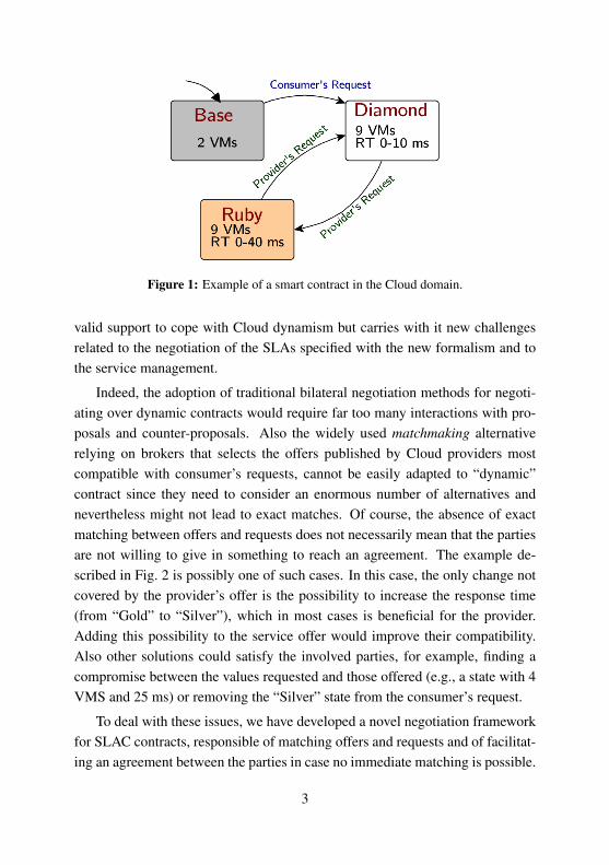
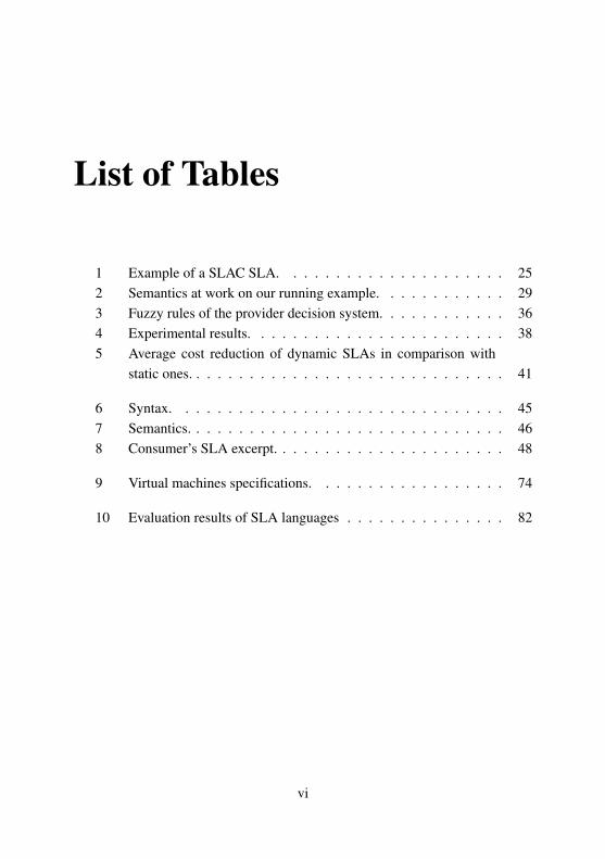
Figure 1: Example of a smart contract in the Cloud domain.
valid support to cope with Cloud dynamism but carries with it new challengesrelated to the negotiation of the SLAs specified with the new formalism and tothe service management.
Indeed, the adoption of traditional bilateral negotiation methods for negoti-ating over dynamic contracts would require far too many interactions with pro-posals and counter-proposals. Also the widely used matchmaking alternativerelying on brokers that selects the offers published by Cloud providers mostcompatible with consumer’s requests, cannot be easily adapted to “dynamic”contract since they need to consider an enormous number of alternatives andnevertheless might not lead to exact matches. Of course, the absence of exactmatching between offers and requests does not necessarily mean that the partiesare not willing to give in something to reach an agreement. The example de-scribed in Fig. 2 is possibly one of such cases. In this case, the only change notcovered by the provider’s offer is the possibility to increase the response time(from “Gold” to “Silver”), which in most cases is beneficial for the provider.Adding this possibility to the service offer would improve their compatibility.Also other solutions could satisfy the involved parties, for example, finding acompromise between the values requested and those offered (e.g., a state with 4VMS and 25 ms) or removing the “Silver” state from the consumer’s request.
To deal with these issues, we have developed a novel negotiation frameworkfor SLAC contracts, responsible of matching offers and requests and of facilitat-ing an agreement between the parties in case no immediate matching is possible.
3
Figure 2: Example of SLA offer/request proposal using SLAC.
Our solution provides a simple formal language for modelling the behaviourof the contracts in terms of transitions and states allowing the representation ofthese models as automata with labels associated to nodes and arcs, as shown inFig. 2. These automata are feed to our software negotiation framework whichassesses the compatibility of offer/request and suggests the changes necessaryfor reaching an agreement.
Afterwards, while analysing scenarios characterized by high dynamism andlooking for a good case study for the application of dynamic SLA, we noticedthat there are still open gaps in the scheduling of latency sensitive services. Wefocused then, on the development of a suitable approach for the initial deploy-ment of service instances. We decided to address latency sensitive scenariosbecause they are highly dynamic and because we could not find any work con-sidering the scheduling problem in Edge platforms, that represent the most suit-able deployment solution for this type of services.
The shift from Cloud to Edge computing has been determined by featuresof the Edge platform from which latency-sensitive services can benefit. Indeed,the currently adopted Cloud-based deployment solutions are not fully suitableto deal with strict latency requirements while the Edge platform represents apromising alternative, since it offers a set of enabling technologies that moveboth computation and storage capabilities (i.e., micro cloud data centres) to theedge of the network, and considerably reduces users’ end-to-end latency. More-over, the Edge infrastructure can be seen as a natural a generalization of theCloud and, thus, it does not requires any change in the specification and ne-
4

Figure 3: Stages of the service life cycle to which the thesis contributes.
gotiation phases, only resource and service management techniques need to bechanged.
However, to effectively exploit the advantages of the Edge infrastructure,service instances need to be scheduled on the node which better fits service re-quirements, taking into account contextual knowledge, i.e., user, application andnetwork information [76]. Indeed, defining an optimal placement allows notonly to maximize user experience by reducing end-to-end latency, but it allowsalso to optimize network traffic by reducing bandwidth consumption and relatedcosts, and improves energy efficiency by reducing the need to offload tasks tothe Cloud which requires more energy than micro data centers.
We propose then, a novel score-based scheduling framework specifically de-signed for latency-sensitive services in Edge. The proposed technique is latency,bandwidth, and resource aware. It schedules each service instance on the VMtype whose computing and network capabilities can optimize service responsetime experienced by end users. First, eligibility of available VM types on edgenodes for hosting given services is evaluated based on VM network and resourcecapabilities, and then such services are scheduled in the most suitable VMs ac-cording to eligibility scores, guaranteeing optimal service quality.
The different stages of a service life cycle in the context of service qual-ity management in Cloud computing, to which this thesis is contributing, are
5

reported in Fig. 3. We devised a framework that considers the first phases ofservices’ life cycle by (i) defining SLAC, a new specification language for thedefinition of dynamic agreements (Chap. 3); (ii) developing a negotiation frame-work suitable for the negotiation of the SLA defined with SLAC (Chap. 4) and(iii) devising a novel scheduling framework for the initial deployment of ser-vice instances in Edge that is specifically tailored for latency-sensitive services(Chap. 5).
In the rest of this chapter, we present the main research questions that havebeen considered in this thesis, and have been a guideline for our work.
Research Question 1How to properly describe service quality terms in Cloud Computing?
The definition of service level agreements specifies the requirements to berespected during the service provisioning. However, Cloud services are inher-ently characterized by a dynamism which makes difficult to properly define theserequirements with current specification languages. This dynamism is related toconsumer and provider needs that continuously change during service execu-tion. Defining static quality terms valid for the whole service life cycle is not themost appropriate approach; a specification language is needed that allows theautonomous modification of the defined requirements, when specific conditionsare met. We address this research question in Chap. 3.
Research Question 2How to negotiate SLAs for Cloud Computing with the new dynamic language?
The adoption of a specification language that allows the definition of servicerequirements that can change at run time without the need of renegotiation, in-troduces new challenges in the negotiation of initial offer/request, since multipleSLA configurations need to be considered. The challenges characterizing thisnew specification language and an innovative framework for the negotiation ofcontracts specified with this new formalism are addressed in Chap. 4.
6

Research Question 3How to enhance specific service quality
in distributed environments?
Edge-based solutions have been proposed for dealing with highly dynamiccomputational requirements of latency sensitive application, but they pose newchallenges for services and resources management. In this context, solutionsare missing for services scheduling; in Chap. 5 we introduce a new frameworkfor the initial deployment of latency-sensitive service instances in Edge-basedarchitectures.
7
Chapter 2
Quality of Service in CloudComputing: Background
In this chapter we provide an overview of the basic concepts related to the maintopics of the thesis. The overall contributions of this chapter are:
• A comprehensive description of the main features of Cloud and EdgeComputing, which represent the background domains of the topics ad-dressed in this thesis.
• An overview of service quality in and its impact on the service life cy-cle phases, which provides a general description of the scenario used toillustrate the works presented in the other chapters.
• A preliminary analysis of smart contracts and of their applicability forService Level Agreements (SLAs) specification in Cloud. These topicswill be further developed in Chap. 3.
• A discussion of the approaches currently adopted for the autonomic nego-tiation of SLAs and for service scheduling in Cloud. This discussion willbe instrumental to introduce the basic notion for the results of Chap. 4 andChap. 5.
8

2.1 Cloud Computing
In the last half century research in the Information and Communication Tech-nology (ICT) area has guranteed significant advances, and nowadays there is anincreasingly perceived vision that computing will one day be the 5th utility, afterwater, electricity, gas and telephony [10]. This vision of computing as utilitycan be found in the advances achieved in the development of the Internet in-frastructure that allowed a worldwide aggregation of computer networks givingthe user the perception of utilizing an endless amount of distributed computingresources, without knowing where they are hosted and how they are delivered.
Several computing paradigms have been developed and adopted over theyears, with the aim to offer computing systems that accurately put this new vi-sion at work: the most important ones being Grid and Cloud computing.
Grid Computing was developed in the mid 1990s to allow consumers to ob-tain computing power on demand [30]. A more formal definition of Grids isgiven in [10]:
A Grid is a type of parallel and distributed system that enablesthe sharing, selection, and aggregation of geographically distributed’autonomous’ resources dynamically at run time depending on theiravailability, capability, performance, cost, and users’ quality-of-service requirements.
On the other hand, in [45], Cloud has been defined as:
Cloud computing is a model for enabling ubiquitous, convenient,on-demand network access to a shared pool of configurable com-puting resources (e.g., networks, servers, storage, applications, andservices) that can be rapidly provisioned and released with minimalmanagement effort or service provider interaction.
Cloud Computing refers mostly to a new operation model that leverages onexisting technologies, such as Grid Computing, Virtualization and AutonomicComputing, to meet the technological and economic requirements of today’sdemand from IT companies [83]. The main reasons making Cloud paradigmmore and more attractive for business in the IT area are reported by Zahong etal. in [83] and listed below:
9
No up-front investment. Cloud offers both hardware and software resourcesusing the pay-as-you-go model, allowing consumers to rent the neededresources according to their needs, without a high initial investment.
Low operating costs. Providers allocate resources to consumers according totheir demand, without over-provisioning, which allows the providers togrant the resources only when actually needed and then to reduce the op-erating costs by taking advantage of the economy of scale (energy, hard-ware, maintenance).
High scalability. Cloud provides two modalities of resource scaling: horizontaland vertical. Horizontal scalability allows the addition or removal of re-source instances (e.g., servers), whereas vertical scalability does not mod-ifies the number of resources but changes the specification of existing ones(e.g., increasing or decreasing the power offered by each server).
Reducing business risks and maintenance expenses. In the scenario where Cloudconsumers demand for hardware resources to a Cloud provider, they movesome of the business risks and maintenance process to the provider.
All the benefits listed above arise from the intrinsic features of the Cloudcomputing paradigm. Indeed, in a Cloud environment, several services fromdifferent consumers can be hosted in a single data-center (multi-tenancy) andthe performance and management issues are ruled by Service Level Agreements(SLAs) subscribed by both the Cloud provider and the service consumers. Tosupport multi-tenancy, Cloud providers offer a pool of resources that can bedynamically assigned to multiple resource consumers (shared resource pooling)allowing service providers to acquire resources according to the current demand(dynamic resource providing) based on a pay-per-use pricing model (uility-basedpricing).
Business models
In this context the term resource refers to both hardware and software compo-nents that are provided to Cloud consumer as-services. Therefore, the adoption
10

of this service-driven operating model brought to the development of three dif-ferent business model, as also reported in the NIST definition of Cloud Comput-ing [45]:
Software as a Service (SaaS). Provider’s applications represent the service de-livered to final users. In this context, users can directly use provider’s ap-plication by accessing it with different type of devices, without any man-agement responsibility. Indeed, only the provider is in charge of managingand controlling the underlying infrastructure.
Platform as a Service (PaaS). Cloud providers offer complete software devel-opment platforms (i.e., operating systems and application developmenttools and frameworks), where consumers can deploy their own applica-tions without any responsibility related to the management of the under-lying software layers.
Infrastructure as a Service (IaaS). Processing, storage, network, and other fun-damental computing resources are provided to consumers who can thendeploy and run any arbitrary software on the top of them. In this model,consumers are responsible of the software infrastructure management, i.e.,they are in charge of installing and configuring the requested resources(e.g., VMs).
Deployment Models
Different deployment models can be adopted in Cloud. The main are:
Private Cloud. A single organization uses the whole Cloud infrastructure, thatis managed by the organization itself or by a third party. Although thismodel offers the highest degree of control of the infrastructure, it is themost similar to traditional server farms, limiting the benefits introducedby the Cloud paradigm.
Public Cloud. A provider offers its resources as services to the general public.The main advantages of this model are represented by no up-front costs oninfrastructure for the consumer and by the shift of risks to infrastructureproviders at the cost of reduced control.
11

Hybrid Cloud. This model combines the previous models and aims at address-ing the limitations characterizing the previous two models.
2.2 Edge Computing
Recently, due to the advances of connectivity infrastructure and the proliferationof Internet of Things (IoTs), new type of services have been introduced that arecharacterized by very strict latency requirements and by high bandwidth demandalong with the need of high computing power for data processing tasks.
Therefore, even though Cloud-based deployment solution still represent theoptimal solution for the processing of large amount of data, the large geographi-cal distribution of Cloud data-centers cannot guarantee the very strict end-to-endlatency required by these services.
Indeed, IoT services are usually related to the processing of data obtainedthrough sensors (e.g., camera,) for pattern matching and data analysis to taketimely decisions (i.e., on the order of very few milliseconds) [19]. Thus, thenetwork latency characterizing Cloud networks cannot cope with these strict re-quirements and the high bandwidth consumption determined by the large amountof data generated by the sensors may turn out to be a bottleneck.
Consequently, innovative distributed computing solutions have been devel-oped allowing the computation tasks to be executed at the Edge of the network,in close proximity of the end users.
This novel computing technology has been named Edge Computing. Thisterm is also often interchanged with Fog Computing, which is mainly related toan actual architectural design of an Edge network [24, 76].
The main idea underneath this new paradigm is to move the Cloud tech-nologies in close proximity of end users [14] for enabling ubiquitous access toa shared network of computing resources and facilitate the deployment of dis-tributed, latency-aware applications and services [34].
An edge node is essentially any type of computing resources and routingdevices in the network along the path from the data source and the Cloud data-centers [61]. In the literature, this set of resources have been grouped in fivedifferent types, namely servers, networking devices, cloudlets, base stations, ve-hicles as reported in [43] and listed below:
12
Servers. Edge servers are usually micro data-centers or nano servers geograph-ically distributed and deployed at highly frequented places (i.e., bus termi-nals, shopping centres, etc.). Similarly to Cloud data-centers, edge serversexploit virtualization technologies to provide storage, computing and net-working facilities.
Networking devices. Networking devices, like gateway routers and switches,provide not only networking functionalities but are also equipped withsome processing power and memory to be used for small data processingtasks.
Cloudlets. Cloudlets are considered as micro-cloud, offering higher amount ofresources compared with other types of devices but acting as centralizedcomponents. Therefore, even if they are deployed at the edge of the net-work they might incur in the same limitations of Cloud Computing.
Base Stations. Traditional base stations are equipped with processing and stor-ing capabilities. However, the main advantages offered by these devices isthe single-hop connection they can provide with the main network back-bone.
Vehicles. The high number of vehicles currently present on the streets can beused to offer a widely distributed and highly scalable Edge environment.Indeed, vehicle are now equipped with exploitable processing and storingcapabilities.
Currently three different Edge architectures have been devised, namely Fogcomputing, Cloudlet and Mobile Edge Computing (MEC)
In the fog architecture, the Edge part is composed of network devices (i.e.,fog nodes) which complement a Cloud infrastructure making computation andstorage functionalities possible anywhere along the path from end users to theCloud data-centers [76]. This platform is most suitable for Internet of Thingsuse cases, because, thanks to the proximity of all fog devices involved, it canguarantees the very strict latency requirements required by those services.
The cloudlet platform, instead, is characterized by a trusted cluster of com-puters well connected to the internet with resources available for use by nearby
13

devices. Cloudlet resources are usually deployed at WiFi access points or net-work base stations offered over a single-hop access with high bandwidth, guar-anteeing then low latency for the deployed applications[24]. This architectureis mostly used for the deployment of applications which requires not only strictlatency requirements, but also high processing power that cannot be provided bythe network devices present in the Fog platform.
The MEC architecture brings computational and storage capacities to theedge of the network within the Radio Access Network to reduce the service end-to-end latency and to improve context awareness [24]. MEC nodes are serversthat are usually co-located with Radio Network Controllers or with macro base-stations. This solution has been mainly devised to allow the offloading of heavyprocessing tasks, that had to be executed on mobile devices, on more powerfulresources, improving the life-time of the device battery. Indeed, user devices cansend task computation on a MEC node that either directly process it or forwardit to the remote data centers.
2.3 Quality of Service in Cloud
Both Cloud consumers and providers expect that applications and services de-ployed on Cloud platforms guarantee high quality services that offer good levelof user experience. In fact, a good service appreciated by users increases alsoproviders’ trustworthiness and thus their revenues.
In this scenario we define service quality as the degree to which a set ofservice characteristics meet the agreed requirements. Specifically, it is as a com-bination of non-functional attributes describing service characteristics that areconsidered relevant for the service-client interaction.
Moreover, these service quality characteristics can be aggregated in twogroups, namely Quality of Experience (QoE) of Quality of Service (QoS) [41].The ones in the first group express a subjective definition of service qualitythrough subjective attributes such as usability, that allow users to express theirpersonal perception about the quality experienced. The ones in the second group,instead, express service quality by means of objective measurable metrics like,e.g., response time and availability. This set of QoS terms, also known as Ser-vice Level Objects (SLOs), is then used for the formal description of the quality
14

requirements to be guaranteed during service provision, defining the so calledService Level Agreements (SLAs)
Here we provide a description of the most common service quality attributes [7].
Availability. Represents the ability of an IT service to perform its agreed func-tion when required. It can be expressed as:
Availability =Agreed Service Time−Outage Downtime
Agreed Service Time(2.1)
where the Agreed Service Time is the period during the measurement win-dow that the system be running, whereas the Outage Downtime representthe total time, still in the measurement window, where the system was notavailable.
Latency. The latency indicator refers to the elapsed time between the sendingof a request and receipt of the reply. Usually it is measured as best thoughtof as a statistical distribution rather than a single value that can crisply bemeasured. It can be specified as a distribution requirements via two pointslike the maximum acceptable latency at both the 90th percentile (slowest1 in 10 transactions) and the 99.999th percentile (slowest 1 in 100,000transactions)
Reliability. Given a logically, syntactically and semantically correct service re-quest, service reliability requirements specify the probability to obtain thecorrect response within the maximum acceptable service latency. Usu-ally it is measured as the percentage of defective (or failed) operations permillion attempts, or DPM, that is:
99.9% service reliability = 1000 defective operations per million
Accessibility. This indicator is related to individual users and defines the proba-bility than he/she can successfully acquire service on demand. The metricused to measure service accessibility is maximum DPM,
Retainability. This metric is related to session-oriented applications and de-notes the probability that an ongoing service session will continue to pro-vide the service under certain conditions for a given time. For example,
15

it represents the probability that a streaming movie plays to the end withno perceptible visual or audible impairments. Metric values may be quan-tified as application sessions per million (DPM) that were prematurelyterminated or as experienced (unacceptable) service impairments.
Throughput. This requirement specifies the minimum number of transitionssuccessfully processed in a given unit of time.
2.4 Service Life Cycle and Quality
As described in Sec. 2.3 service consumers and providers specify the servicequality to be guaranteed throughout the whole service provision by means of aset of non-functional attributes that are relevant for the service-client interaction.
These requirements, the so called SLOs, are then formalized in a contract,the Service Level Agreement (SLA), that specifies the quality guarantees to berespected and enforced during the service provision as well as the actions to betaken when the guarantees are violated.
More in detail, a SLA is the contract legally binding service consumers andproviders and is concerned with:
• The parties involved in the agreements, specifying their roles and respon-sibilities.
• The functional aspects of the provided service.
• The set of obligations and guarantees imposed on each party related tothe service provision.
• The service quality attributes (i.e., QoS terms) specifying the non-functionalrequirements, focused on quality aspects (e.g., service response time) tobe guaranteed during the service provision.
• The timing and condition for the validity of the contract.
This contract is also characterized by a specific life cycle which is tightlycoupled with the service life cycle, as depicted in Fig. 4. Here we describe eachphase of the SLA life cycle and how it is related to the service one.
16
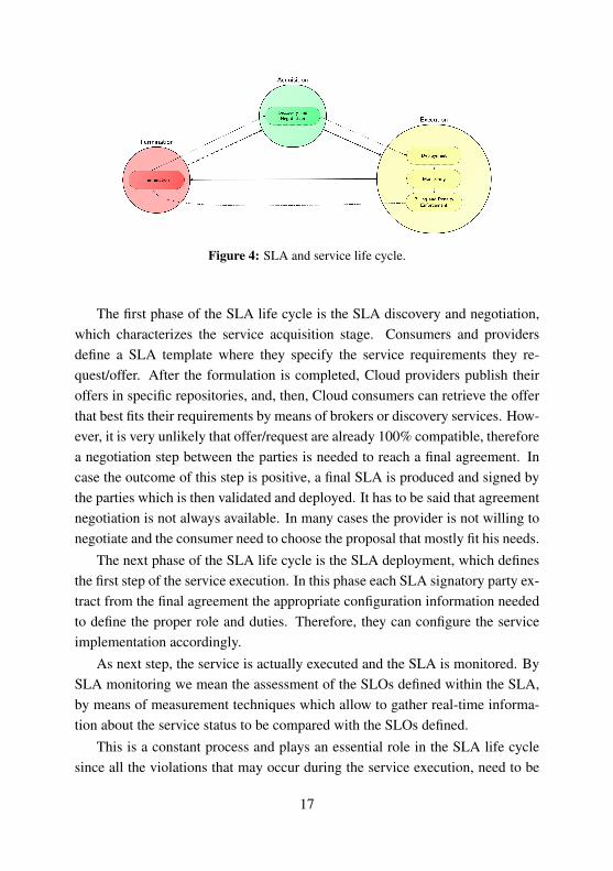
Figure 4: SLA and service life cycle.
The first phase of the SLA life cycle is the SLA discovery and negotiation,which characterizes the service acquisition stage. Consumers and providersdefine a SLA template where they specify the service requirements they re-quest/offer. After the formulation is completed, Cloud providers publish theiroffers in specific repositories, and, then, Cloud consumers can retrieve the offerthat best fits their requirements by means of brokers or discovery services. How-ever, it is very unlikely that offer/request are already 100% compatible, thereforea negotiation step between the parties is needed to reach a final agreement. Incase the outcome of this step is positive, a final SLA is produced and signed bythe parties which is then validated and deployed. It has to be said that agreementnegotiation is not always available. In many cases the provider is not willing tonegotiate and the consumer need to choose the proposal that mostly fit his needs.
The next phase of the SLA life cycle is the SLA deployment, which definesthe first step of the service execution. In this phase each SLA signatory party ex-tract from the final agreement the appropriate configuration information neededto define the proper role and duties. Therefore, they can configure the serviceimplementation accordingly.
As next step, the service is actually executed and the SLA is monitored. BySLA monitoring we mean the assessment of the SLOs defined within the SLA,by means of measurement techniques which allow to gather real-time informa-tion about the service status to be compared with the SLOs defined.
This is a constant process and plays an essential role in the SLA life cyclesince all the violations that may occur during the service execution, need to be
17

forwarded to the party in charge for the billing and for penalty enforcement.In this phase of the SLA life cycle the penalties defined in the SLA are en-
forced and corrective actions are executed by the service provider. If the vio-lation is not critical, service management actions are carried out, otherwise theprovider can ask the consumer to renegotiate the SLA terms to reduce the riskof violating the requirements again. Together with penalty enforcement alsobilling activities are periodically executed. These activities determines whetherthe SLA terms are met, the amount to be paid by the consumer and the overallpenalties to be paid by the provider.
The last phase of service and SLA life cycles is the termination phase whereservice consumer and provider terminate service execution and the SLA is archived.
2.5 Smart Contracts
A first definition of smart contracts is provided by Nick Szabo in [65]:
A smart contract is a set of promises, specified in digital form, in-cluding protocols within which the parties perform on these promises.
A more detailed one is given, instead, in the white paper issued by the Cham-ber of Digital Commerce [2] which defines a smart contract as a set of contrac-tual terms and/or rule-based operations, embedded as code within a software,designed to carry out business logic. A protocol, in the form of an algorithm,constitutes a set of rules for how each party should process data in relation to asmart contract.
Essentially, this type of agreement represents the formalisation of an agree-ment, whose terms, such as payment, confidentiality and quality, are automat-ically enforced by relying on a previously agreed protocol without the need ofthird-party trusted intermediaries.
Such contracts may specify not only the required service and its quality butalso the possible changes at run time of the terms of agreement through thedefinition of conditions and actions.
Several application fields have been reported in [2], ranging from digitalidentity to clinical trials but they are currently mostly used in the area of cryp-tocurrencies (e.g., Ethereum and Bitcoin).
18

In the area of Cloud computing, with their automatised enforcement and withsolutions to deal with the dynamic nature of Cloud, the SLAs can be consideredequivalent to smart contracts. However, current SLA definition languages pro-vide only the possibility to specify static agreements that cannot be automaticallychanged at run time, In case adjustments are needed, a renegotiation process hasto take place.
Further motivations and details about the application of smart contracts inCloud and a possible use case scenario are provided in Chap. 3.
2.6 SLA Negotiation in Cloud
In the previous section we briefly discussed the advantages of smart contractsfor the SLA specification. However, the adoption of this new formalism intro-duces also new challenges for the SLA negotiation process. Essentially, in thisprocess, consumer and provider negotiate over service requirements, guaranteeand obligations aiming at finding a definite mutual agreement.
Different types of negotiation can take place according to the number ofparties involved [6]
One-to-one. This is the most common scenario; a consumer and a providerdirectly bargain for the acquisition of an item or a service.
One-to-many. In this context a consumer negotiates with several providers orbusinesses.
Many-to-one. This is a less common scenario; different consumers negotiatewith single provider or company.
Many-to-many. Several consumers and providers are involved in the negotia-tion process. A typical example is provided by the negotiation betweenunions and employees where companies cooperate to reach an integratedagreement that saves their interests and unions bargain to get the best ben-efits from the employers they represent.
Moreover, each type of negotiation relies on three main components:
19

Negotiation objects. The negotiation objects are essentially the set of termssubject of negotiation.
Protocol. The rules specifying the negotiation process (i,e.,number of partici-pants and their roles), the interaction among the negotiators and the legalactions that the participants can take depending on the state of the negoti-ation, are the main components of a negotiation protocol.
Decision models. Each party establishes a decision model to elaborate the ne-gotiation moves to achieve their objectives.
However, when considering smart contracts, some of the negotiation com-ponents described before, namely objects and models, considerably change. In-deed, negotiation objects are not fixed, and the conditions and the modificationactions specified by each negotiation party may change. Also, the dynamicityof the objects considered in a smart contract requires changes of the negotiationmodels, currently devised for bargaining over static terms.
A more detailed analysis of the limitations and of current negotiation solu-tions for the negotiation of smart contracts is presented in Sec. 6, and a newframework better suitable for this process is presented in Chap. 4.
2.7 Service Scheduling
Scheduling in Cloud Computing refers to the set of techniques and policiesadopted for the autonomous management of services and resources to achieve ahigh performance computing and high system throughput [79].
More specifically, the scheduling process defines the order of servicing in-coming services and the resources to be used for their execution, according toQoS terms, costs, revenues for Cloud providers, and users experience.
The three main steps that characterizing scheduling, reported in [59], arehereby described:
Resource discovering and filtering. A resource broker is in charge to discoverresource availability and status information.
20

Resource selection. According to the resource information retrieved by the bro-ker, the selection step assigns the available resources to all the services tobe executed.
Task submission. Services are finally executed on the assigned resources.
Many approaches to resource scheduling have been followed. They rangefrom very simple heuristic-based approaches, such as the Minimum ExecutionTime and Minimum Completion Time [46] to more advanced ones based ongenetic algorithms and simulated annealing [35, 60]. However, the applicationof these solutions on higly distributed environments as those considered by theEdge Computing paradigm is not straightforward.
Indeed, both resource discover and selection processes developed for thescheduling algorithms currently used for Cloud, do not take into account infras-tructural features and user-related information in their decision process.
In Sec. 6 we provide a more comprehensive analysis of the limitations ofcurrent scheduling algorithms for Cloud in the Edge scenario while an innovativeframework for service scheduling in Edge is presented in Chap. 5.
21

Chapter 3
Dynamic Service LevelAgreements
In this chapter we introduce SLAC, a novel SLA specification language specif-ically devised for Cloud which encompasses a mechanism for the definition ofdynamic modifications of the agreements. This new specification language ad-dresses the dynamism of the service requirements allowing the specification ofmodification actions that can automatically change the service terms, at runtime,when specific conditions are met. Essentially, this formalism define SLAs assmart contracts offering an enhanced specification of service requirements, pro-viding a solution for the Research Question 1.
The main features introduced by the devised language are:
• A formally defined syntax and semantics to have non-ambiguous SLAs;
• A number of software tools to support services deployment;
• A novel mechanism to guarantee flexibility and elasticity to the involvedparties;
• A brokering mechanism that supports multi-party contracts.
The rest of the chapter is organised as follows. Sec. 3.1 gives a compre-hensive overview on the SLAC language. Sec. 3.2 illustrates the SLAC software
22

Figure 5: Example of a dynamic SLA in the Cloud domain.
framework. Sec. 3.3 describes the experiments showing the advantages of SLACand dynamic SLAs.
3.1 The SLAC Language
The novelties introduced by the SLAC language enable the specification of dy-namic SLAs that allow the parties signing the contract to specify not only theservice requirements and quality, but also the modifications that can be appliedat runtime to change the valid terms of the agreements.
Indeed, the parties can specify, in addition to the initial agreement, the con-ditions and the actions that, at runtime, can change the enforced terms of thecontract; for example, a consumer can add virtual machines at any time payingthe market price plus 0.01 EUR. This allows the formalisation of the horizontaland vertical scalability as well as changes in the service levels.
Therefore, this language, at specification level, is compatible with the con-cept of smart contracts described in Chap. 2.5, since it enables the parties to de-fine a set of modification actions which can be executed to automatically changethe SLA terms at runtime.
For this reason, throughout the whole thesis we will use the terms dynamicSLAs and smart contracts interchangeably.
A further example of dynamic agreements is depicted in Fig. 5. The initialvalid terms of the SLA characterizes the “Base” service quality, with 2 VirtualMachines (VMs) provided and no requirement about Response Time (RT). Dur-ing service execution, the consumer may request the upgrade of the quality to
23

Figure 6: Overview of the main components of a SLA written in SLAC.
“Gold”, to get more VMs and the guarantee that RT does not exceed a giventhreshold. Now, if the RT requirement is violated (due to, e.g., overbooking ofresources), the service quality is downgraded to the “Silver” level, where the RTrequirement is relaxed. The SLA terms are automatically upgraded again to the“Gold” quality when the service workload goes back to a normal level.
For the sake of readability, we focus on an informal description of the lan-guage components and their role in the SLA, by resorting to an illustrative ex-ample. The formal definitions of the SLAC syntax and semantics, specified inEBNF and denotational style, respectively, are available in an online technicalreport [69].
3.1.1 Overview of the Syntax
The distinctive features that differentiate SLAC from other SLA languages canbe summarized by saying that SLAC is a domain specific formal language specif-ically designed for Cloud services that supports the main Cloud deploymentmodels, enables the specification of multi-party agreements and permits dy-namic changes of SLA according to pre-defined conditions.
Fig. 6 depicts the main components of a SLA defined using SLAC. We in-formally present them via the SLA example, reported in Tab. 1, which refers tothe brokered provision of a IaaS service, assessed by an auditor.
SLA Description. This component defines the validity period (start andexpiration time) and the parties involved in the provision of the services. Aparty is defined by its name and its roles. In the running example, the validity of
24

Table 1: Example of a SLAC SLA.
1 Effective From: 01/09/2017 36 replace S VM UNICAM with S VM IMT2 Expiration Date: 01/09/2018 37 on IMT request:3 Parties: 38 if L VM > 1:4 IMT Roles: Broker, Provider 39 replace value of
L VM.Availability with 97%5 UNICAM Roles: Provider 40 on IMT request:6 Alice Roles: Consumer 41 replace value of
41 L VM.Availability with 99%7 Bob Roles: Auditor 42 Invariants:8 Term Groups: 43 L VM in [0,2]9 S VM IMT: 44 Monitoring:10 IMT→ Alice:cCpu 2 # 45 S VM IMT.Availability:11 IMT→ Alice:RAM 4 GB 46 Frequency: 10 s12 IMT→ Alice:Availability 99% 47 Window: 1 months13 IMT→ Alice:Price 0.20 EUR 48 By: Bob14 S VM UNICAM: 49 S VM UNICAM.Availability:15 UNICAM→ Alice:cCpu 2 # 50 Frequency: 10 s16 UNICAM→ Alice:RAM 4 GB 51 Window: 20 days17 UNICAM→ Alice:Availability 98% 52 By: Bob18 UNICAM→ IMT:Price 0.16 EUR 53 L VM.Availability:19 IMT→ Alice:Price 0.20 EUR 54 Frequency: 6 s20 L VM: 55 Window: 15 days21 IMT→ Alice:cCpu 4 # 56 By: Bob22 IMT→ Alice:RAM 8 GB 57 Guarantees:23 IMT→ Alice:Availability 99% 58 on violation of any.Availability:24 IMT→ Alice:Price 0.35 EUR 59 if Availability > 95%:25 Terms: 60 IMT→ Alice: Bonus 1 EUR26 1 of S VM IMT 61 else:27 Dynamicity: 62 IMT→ Alice: Bonus 2 EUR28 on Alice request: 63 on violation of any.Frequency:29 replace S VM IMT with L VM or 64 Bob→ IMT,Alice: notify30 replace S VM UNICAM with L VM 65 Billing:31 on Alice request: 66 accounting: hourly32 replace value of L VM with old+1 or 67 billing: monthly33 replace value of L VM with old-134 on IMT request:35 replace S VM IMT with S VM UNICAM or
25

the SLA (lines 1-2) is one year. The involved parties (lines 3-7) are instead four:two providers (IMT and UNICAM), a consumer (Alice) and an auditor (Bob). TheIMT party has two roles; it acts also as a broker and, when necessary, it mayresort to UNICAM for offering the small VM service to Alice.
Service Description. This component specifies the details of the service andits quality. It consists of two parts: groups of terms and instantiation of the validterms (lines 8-26 of the example). The terms of the agreement express the char-acteristics of the service along with their expected values. Moreover, for eachterm SLAC requires to specify the involved parties, i.e., the party responsiblefor fulfilling the term (a single party) and the contractors of the service (one ormore). In our example, for instance, the term IMT→ Alice:Availability 99%
indicates that the party IMT provides to the party Alice the service (i.e., one ormore virtual machines) with an availability of (at least) 99%. The explicit defi-nition of the involved parties contributes to supporting multi-party agreements,reducing ambiguity and leveraging the role of the broker. Moreover, it improvesprivacy and security of the agreement; only parties involved in the term haveaccess to it. For example, when the small VM service is provided by UNICAM,the SLA specification (lines 18-19) indicates both the cost that IMT, as a broker,has to pay to UNICAM, and the cost that Alice has to pay to IMT, which in factis the same she pays when the service is provided directly by IMT. However, theformer information is not accessible to the consumer, who is kept unaware of theagreements between the broker and the providers.Notably, the language offers aset of pre-defined metrics devised for IaaS. Yet, new metrics and their measure-ment definition can be easily defined without affecting the general language. Fora detailed account on this extension procedure we refer to [40].
Another feature of the language is the use of groups to specify terms ofagreements with different granularities. A group of terms is identified by a name(unique in the contract) and consists of one or more terms that are valid onlyinside the group. In the example, we have three groups that represent differ-ent types of virtual machines: small VMs provided by IMT (S VM IMT) and byUNICAM (S VM UNICAM), and large VMs (L VM). Notably, to use a group in a SLAdefinition, it is not sufficient to define it, but it is also necessary to instantiateit by specifying the number of instances. For example, the code in lines 25-26permits to actually deploy one instance of the S VM IMT group in the SLA.
26

Dynamic aspects. This component of the agreement is optional, but it is oneof the main novelties of SLAC. Thanks to this, the user can possible run timechanges of the enforceable terms of agreement, through the definition of Event-Condition-Actions (ECA) rules. When an event occurs (e.g., a party makes anexplicit request), a condition (defined by an expression) is checked and the ex-ecution of one or more actions is requested (e.g., the change of the value of agiven metric). These rules, for instance, permit agreeing on unilateral changesfrom one of the parties; e.g., it can be agreed that a party can request changes inthe service that can be implemented without the authorisation of other parties.In our example, the consumer can change the type of VM (lines 28-30) and addor remove as many L VMs as necessary (lines 31-33). Instead, the broker canfreely change the provider of a small VM service (lines 34-36) and change theavailability of large VMs (lines 37-41), with the constraint that the reduction ofavailability is allowed only in case more than one L VM is instantiated. Replace-ment actions can use a reserved variable name old to refer to the current valueof the term metric or to the number of instances of a given group.
The Invariants section constrains the changes agreed in the Dynamicity
section, by fixing bounds for terms of the contract. When an event triggeringchanges of the contract is detected, the corresponding changes are applied onlyif they are compliant with the invariants terms. In our example, an invariant isused to specify that the consumer cannot request more than 2 large VMs.
Monitoring. This SLA component specifies monitoring requirements to ob-tain information for configuring the monitoring system and defining the audit-ing agreement. In the example, the Availability metric is monitored by theAuditor with different accuracy depending on the virtual machine type. Forexample, the availability of the (more expensive) large VMs is checked by Bob
more frequently within a smaller time window.
Guarantees. This (optional) component is concerned with the enforcementof the terms of agreement and specifies the actions to be taken in case of viola-tions. Specifically, a guarantee is an ECA rule, where the event typically refersto a term defined in the Terms section of the agreement. In our running example,if the Availability of any (large or small) VM is violated, but it is still greaterthan 95%, the broker needs to give a bonus of 1 EUR to the consumer, whilst ifit is less than or equal to 95% the penalty is doubled (lines 58-62). Moreover,
27

if a requirement about the monitoring frequency is violated (due to, e.g., main-tenance activity of the provider), the auditor is required to notify the issue toprovider and consumer (lines 63-64).
Billing. Since SLAC enables modification of the valid terms at runtime, itis necessary to define periods of accounting and the frequency of billing. Inour scenario we defined the accounting period in hours and the billing monthly.Thus, if the consumer used a small VM for 48 hours and then requested a largeVM, after one month, the service will be accounted for 48 hours at the price 0.20EUR/h, and at 0.35 EUR/h for the other days of the month.
3.1.2 Informal Semantics
Intuitively, the SLAC’s formal semantics associates a constraint to each StaticSLA. It is formulated as a Constraint Satisfaction Problem (CSP), which is eval-uated, at design-time, to identify inconsistencies in the specification and, at runtime, to check compliance with the monitoring data collected from the Cloudsystem. To support dynamic SLAs, extensions are needed to allow the use ofdynamic CSP [75]. Now, a dynamic SLA is represented as an automaton, whosestates, representing the SLA states, are labelled by constraints, and whose tran-sitions are labelled by events that trigger the state changes.
At run time, data representing the status of the Cloud are collected by themonitoring system and rendered as a CSP. Then, the CSPs of (the current stateof) the SLA and of the monitoring data are combined for evaluation. After suchan evaluation, the guarantees specified in the SLA are evaluated and, possibly,the execution of some action is requested to the Cloud manager. Similarly, theECA rules of the Dynamicity section are evaluated; for each applicable rule,the terms of the Invariants section are checked in order to apply only thosechanges that are compliant with the invariants.
More formally, the semantics of a Static SLA, or of a single state of a dy-namic SLA, is given by a function J·K that given the SLA terms returns a paircomposed of a set of group definitions and a constraint. This pair constitutes theCSP associated to (a state of) the agreement, that will be solved by means of astandard constraint solver as described in the next subsection. The automatonrepresenting the semantics of a dynamic SLA is generated as follows. The ini-
28
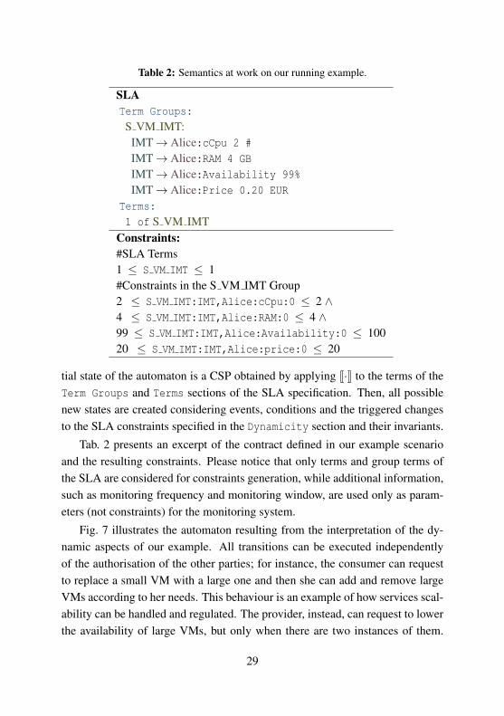
Table 2: Semantics at work on our running example.
SLATerm Groups:
S VM IMT:IMT→ Alice:cCpu 2 #
IMT→ Alice:RAM 4 GB
IMT→ Alice:Availability 99%
IMT→ Alice:Price 0.20 EUR
Terms:
1 of S VM IMTConstraints:#SLA Terms1 ≤ S VM IMT ≤ 1#Constraints in the S VM IMT Group2 ≤ S VM IMT:IMT,Alice:cCpu:0 ≤ 2 ∧4 ≤ S VM IMT:IMT,Alice:RAM:0 ≤ 4 ∧99 ≤ S VM IMT:IMT,Alice:Availability:0 ≤ 10020 ≤ S VM IMT:IMT,Alice:price:0 ≤ 20
tial state of the automaton is a CSP obtained by applying J·K to the terms of theTerm Groups and Terms sections of the SLA specification. Then, all possiblenew states are created considering events, conditions and the triggered changesto the SLA constraints specified in the Dynamicity section and their invariants.
Tab. 2 presents an excerpt of the contract defined in our example scenarioand the resulting constraints. Please notice that only terms and group terms ofthe SLA are considered for constraints generation, while additional information,such as monitoring frequency and monitoring window, are used only as param-eters (not constraints) for the monitoring system.
Fig. 7 illustrates the automaton resulting from the interpretation of the dy-namic aspects of our example. All transitions can be executed independentlyof the authorisation of the other parties; for instance, the consumer can requestto replace a small VM with a large one and then she can add and remove largeVMs according to her needs. This behaviour is an example of how services scal-ability can be handled and regulated. The provider, instead, can request to lowerthe availability of large VMs, but only when there are two instances of them.
29

Figure 7: The automaton for the running example.
Notably, if the consumer reduces the number of large VMs to less than two, theavailability remains at 97%.
3.2 The SLAC Software Framework
To support the use of SLAC, we developed an open source software frameworkthat covers the whole SLA life cycle. The current prototypical version of theframework1 works in a centralised fashion and its modules were developed usingthe Python programming language. Fig. 8 illustrates the main modules of theframework.
The SLAC Web Editor can be used by consumers and providers to defineSLAs, and to offer or request services. The editor performs auto-completion andsyntax verification and was developed using Xtext2, a framework supporting theimplementation of domain specific languages. If a final SLA is defined (e.g.,
1Available on http://sysma.imtlucca.it/tools/slac/2https://eclipse.org/Xtext/
30

Figure 8: SLAC Management Framework: evaluation process.
due to a previous negotiation or in case of a fixed service), the negotiation phaseis skipped. Otherwise, providers and consumers send their offers/request to abroker to match and negotiate services.
The Broker matches offers and requests of (dynamic) SLAs. Consideringthe difficulties of analysing and matching such SLAs, in [57] we proposed andimplemented a brokering solution that autonomously matches the compatibleoffers and defines the final SLA based on the policies and on the preferences ofthe parties.
The Service Executor receives and processes the SLA created in the previousphase and automatically deploys and executes the service; but before doing thisit asks the SLAC Evaluator to check SLA’s consistencies and also filters theservice specifications related to the deployment of the services. The Executoruses a scheduler, based on machine learning solutions defined in [73], that wehave integrated within the Cloud management tool OpenNebula3.
The SLAC Evaluator accepts as input a SLA, parses it and generates a setof constraints, corresponding to the specification along with the service defini-tion, that are sent back to the Service Executor (also in case of changes in thestate of the SLA). After that, the Evaluator sets up the Monitoring System (inour case, Panoptes [74]) to retrieve the data concerning the metrics related tothe SLA. Then, the SLA Evaluator receives the monitoring data and transformsthem into a set of constraints, whose satisfiability is verified together with SLAconstraints. In case of non-satisfiability, the SLA guarantees are evaluated and
3http://opennebula.org
31

the due actions are activated. The Evaluator parses the SLA with the ANTLR44,by relying on the language’s EBNF grammar. The constraints are handled bythe Evaluator using the Z3 solver [20]. It is worth noticing that not all monitor-ing data are required when evaluating constraints; thus evaluation with partialobservations of systems is possible.
The Billing and Penalty Enforcement module calculates costs and penalties,and bills the parties when scheduled or when traces and events (e.g., violationsor changes in the service) are received.
Our software framework supports and automates all phases of the new lifecycle proposed in Sec. 2.4:
Service Discovery. SLAC supports the definition of the needs of consumers andavailable resources of the providers and integrates the solution providedin [57] to verify the compatibility of offers and requests.
Negotiation. A brokering solution to support negotiation of dynamic SLAs isproposed in Chap. 4 and integrated in our framework.
Deployment. The Service Executor is integrated with the OpenNebula toolkitto enable the automatic deployment of services.
Monitoring. The monitoring system Panoptes is automatically configured tomonitor the terms of the SLA, while the Evaluator listens to events orrequests, processes the modifications, logs them, and requests the changesof terms to the Service Executor.
Billing and Penalty Enforcement. A specific framework module is responsi-ble for this phase of the life cycle.
Termination. The SLA termination is handled by the Billing and Penalty En-forcement module.
3.3 Experiments
This section presents our experimentations to assess the benefits of the frame-work for both providers and consumers.
4http://www.antlr.org/
32

3.3.1 Provider’s Benefits
To illustrate the benefits of dynamic SLAs, we use a Cloud testbed with Cloudservices provided to multiple consumers. We compare three different approaches:static SLAs (SLAs do not change during their lifetime), renegotiation (partiescan renegotiate the existing SLAs) and dynamic SLAs (terms of agreements canbe dynamically changed). For the comparison, we analyse the number of viola-tions, the penalties and the total revenue of the provider. The obtained results,discussed below, demonstrate the flexibility of SLAC and its capacity to reducethe number of SLA violations and to improve the revenue of the involved parties.
Use Case Implementation
For implementing the use case, we have embedded the SLAC software frame-work in a Cloud testbed. The resulting Cloud system has several components(see Fig. 9). The SLAC Evaluator parses and evaluates SLAs for the servicespecification and requirements, and sends the outcome to the Service Executor.This component is specifically designed to guarantee the correct deploymentand execution of services, and to manage the Cloud infrastructure; it schedulesservices using the approach presented in [72, 73]. The Panoptes Monitoring Sys-tem provides the status of the system and services to the Violation Risk Analyserand to the SLAC Evaluator, and is directly configured by the Service Execu-tor. Specifically, the Violation Risk Analyser measures the risk of the runningservices of not meeting the deadline specified in the SLA, and notifies the Rene-gotiation Decision System. The violation risk analysis is performed using theSupervised Random Forest technique [9], and is based on the monitoring in-formation and on the SLA itself. Finally, the Renegotiation Decision Systemcreates proposals for modifying the SLA and decides whether to accept changesin the services.
In the experiments, each service is processed according to the workflow de-scription depicted in Fig. 10. It is evaluated only once during its execution life-time, at time tr, a random time between the starting and the deadline of theservice. In case of static SLAs, the services are computed employing the SLAdefined at design time. When the service ends or the deadline is met, the systemverifies whether the SLA was violated and determines the price and the possible
33

Figure 9: Components of the use case implementation.
penalties. In the renegotiation approach, the violation risk is measured first. Ifit is not higher or lower than given thresholds, the service is provided normallyaccording to the SLA defined at design time. When renegotiating, a party sendsa SLA proposal to the other party, who analyses it according to its prioritiesusing a Fuzzy Decision System (see below). If the new agreement is accepted,the service continues and it is evaluated considering the new SLA, otherwisethe initially defined agreement remains valid till the end of the service. The dy-namic approach is similar to the renegotiation one, the only difference is thatthe involved parties do not have any active role. Indeed, in case of low or highviolation risk, the agreement is modified automatically since the changes arepre-defined in the SLA. In both cases, to motivate or compensate a party for thechanges, a bonus is given to the other party when a change is performed dur-ing the service execution. Although the bonus a priori is usually much smallerthan the bonus required for renegotiating the SLA during the execution, for thesake of simplicity, we opt to use the same range of values of the renegotiationapproach.
Fuzzy Decision System
To decide whether to accept or refuse a new agreement, the renegotiation ap-proach needs to know the difference between the original agreement and theSLA proposed at renegotiation time. In our use case, to simulate this process,which is typically carried out by a human or by an autonomous decision system,
34

Figure 10: Flow diagram of the service processing for the Static, Renegotiation anddynamic approaches.
we designed a fuzzy logic decision support system inspired by the approachpresented in [22].
The decision system takes as input the rates of change for the consideredparameters, e.g., the increment in price and decides whether the new SLA isbeneficial, neutral or not beneficial to the party. In the case of consumers, thesystem takes into account also their priorities. In our use case, the inputs are:the deadline for the service (D), the price to be paid for the service (Pr) and thepenalty in case of violation (Pe). Tab. 3 exemplifies some rules that are usedby the provider’s fuzzy decision system. For a complete account of the fuzzyrules and the framework used in the experiments, we refer to the SLAC project’swebsite [68].
35

Table 3: Fuzzy rules of the provider decision system.
Rule EvaluationPe increases not beneficial
Pr or D increases beneficialPr and D increase very beneficialPe increase < 10% neutral
Evaluation
The experiments were conducted with a Cloud with 2 physical machines, pro-viding 12 heterogeneous VMs, in which agents are used to execute services.
Services are generated taking into account the distribution of a trace of areal-world Cloud environment, the Google’s Cloud dataset [55], and the sameservices are executed using all three described approaches. Each service has anassociated SLA, which is created along with the service, according to an esti-mation of the resources necessary to finish the service within the completiontime. The considered features are: CPU, RAM, requirements, disk space, com-pletion time and network bandwidth. Different types of services are used in theexperiments, such as web crawling, word count, number generation and formatconversion, which are close to real-world applications [47]. Service’s penaltiesand prices are generated along with the SLA and are based on the service execu-tion time and on a randomly defined number. Penalties are always higher thanthe price, since the price is paid even if a service is violated.
The training set for the SLA Risk assessment module is built for every ex-periment round by executing 1000 services. Then, it is used to train the machinelearning algorithm to provide the probability of classifying a new service intothe violated and not violated classes. In each round, new services are gener-ated (for creating the training set and for testing the approaches) and the sameservices are executed for all approaches. The number of services ranges from100 to 500 (with 50 services interval). We assume that the services’ arrival is aPoisson process, i.e. the time between consecutive arrivals has an exponentialdistribution and that a service arrives, on average, every 0.7 seconds.
The Fuzzy decision system accepts proposals which are beneficial to therequested party. Therefore, the requester and the Renegotiation decision system
36

usually offer compensations for the requested party that fulfills the need of therequester; for example, if the violation risk is high, the provider requests moretime to finish the service but offers a discount on the price and a higher penalty.The definition of the exact parameters of the considered metrics of the SLAmodification proposal, which are used by the renegotiation and the dynamicapproaches are randomly generated within a predefined range. The results of
100 150 200 250 300 350 400 450 500
Number of Services
100
200
300
400
500
600
700
800
900
Pen
alt
y
DynamicRenegotiationStatic
100 150 200 250 300 350 400 450 500Number of Services
0
500
1000
1500
2000
2500
3000
Reve
nue
StaticRenegotiationDynamic
100 150 200 250 300 350 400 450 500Number of Services
10
20
30
40
50
60
70
Viol
atio
ns
DynamicRenegotiationStatic
100 150 200 250 300 350 400 450 500Number of Services
0
20
40
60
80
100
120
Mod
ifica
tion
s
DynamicRenegotiationRequests (Renegotiation)
Figure 11: Performance analysis.
these experiments are illustrated in Fig. 11 where different numbers of servicesare considered. Tab. 4 presents the overall results, relative to the renegotiationand the dynamic approach, expressed as percentages: in the case of penalties andrevenue, the results correspond to a comparison with the static approach, whilstfor the other features they result from a comparison with the total number ofservices. Considering the parameters defined for the renegotiation approach andthe benefit threshold used in the experiments, around 60% of the modificationrequests were accepted and carried out. Using the dynamic approach, 21% ofthe services were modified mainly due to high risk of violation (more than 19%).The total number of modifications is relatively high due to the accuracy of themachine learning algorithm, in which we prioritised the identification of high-risk SLAs. Consequently, the number of false positives increased, i.e., someSLAs that normally would not be classified as high-risk were considered so.In the renegotiation and dynamic approaches, 14% and 19% of the SLAs are
37

classified as high-risk.
Table 4: Experimental results.
Renegotiation DynamicModification Requests 24% 0%
Modifications 13% 21%High Risk 11% 19%Low Risk 0.1 % 0.2%
Violated High Risk 19% 14%Violated Low Risk 0% 3%
Penalties -31% -64%Revenue 13% 22%
Overall, the flexibility provided by the dynamic approach increased the rev-enue by 22% and reduced the penalties by 64%, whilst these measures were only13% and 31% for the renegotiation approach.
Experiments’ Discussion
In the experiments, the benefits of renegotiation and dynamicity heavily dependon the accuracy of the violation risk analyses. The results show that, although thepenalties were reduced by 64%, the impact on the total revenue was an increaseof around 22%. The main reasons for this difference are: (i) the limited impactof the penalties on the total revenue due to the average number of violations; (ii)the compensation provided to the consumers when a modification is requested,which lowers the price paid for that service and sets higher penalties in case ofviolation; (iii) the number of modified SLAs which were violated since most ofthe modification requests increase the penalty as a compensation for the higherservice completion time. This suggests that performing an analysis to definethe additional time required to avoid violations instead of generating a randomnumber could improve the total revenue.
The experiments were focused on avoiding SLA violations, and in few casesdynamicity and renegotiation were used to improve the revenue of the parties(only around 1.4% of the services were considered low-risk). In most scenarios,these mechanisms can be more aggressively employed to improve the revenue,exploiting improved accuracy of the risk analyser.
38

Also, the parameters defined in the SLA modification proposal may have aconsiderable impact on the results. We adjusted these parameters to simulate areal-world situation, where every party defends his interest.
We can conclude by saying that the results demonstrate that SLAC providesflexibility for the parties and significantly optimises SLA management. And,it can always be used together with the renegotiation approach in case not allrelevant modifications are included in the SLA.
3.3.2 User’s Benefits
The benefits of dynamic SLAs for consumers are manifold; here we focus on theeconomic impact by discussing a scenario where we compare static and dynamicSLAs. We do not cover the benefits of having guarantees for the dynamic partof the service, since these benefits are difficult to measure.
In our scenario, we compare standard Cloud offers, using static SLAs, withoffers based on dynamic SLAs. The former provide a fixed amount of re-sources for a fixed price during the duration of the SLA, while the latter providemore flexible solutions. The dynamic approach is common in various domains;e.g., telecommunication companies normally offer a mobile plan that providesa bonus (more calls and messages) for the first six months and then the serviceis changed. In the Cloud domain, there are similar offers but they are typicallydefined in natural language and cannot be automatised.
In our scenario, an infrastructure provider offers one static service, where aVM costs 0.36 EUR, has 2 GB of RAM and 1 CPU; and two dynamic services,with the same initial characteristics. In the first dynamic offer, called Small, theconsumer must deploy a minimum number of VMs for the duration of the SLAbut has two advantages: the price, which is 0.32 EUR, and the capacity of theVMs that, between 22:00 and 7:00, have 1 additional GB of RAM. The seconddynamic offer, called Big, requires at least twice the minimum number of VMsof Small, but the price is 0.29 EUR and at night the active VMs have additional2 GB of RAM.
The consumers in this scenario need an infrastructure to run their websites.Thus, the performance of VMs can be also simplified to the maximum requestsper hour supported by each VM. All the offers during the day support 1200
39

Figure 12: Experiment scenario used to measure the economic impact for con-sumers.
requests/hour, considering an average size of page in our dataset. At night, thestatic offer supports the same number of requests per hour, i.e. 1200, while theSmall supports 1400 and the Big 1600. The change of the capacity at 22:00 andat 7:00 is automated through the definition of dynamic SLAs, which describealso the minimum VMs per hour.
To measure the impact on consumers, we use a dataset with the real traces ofall Wikipedia HTTP requests for 20 days of October 2007 [67]. Then, each timethe experiment is run, we select randomly 50 pages of the dataset, filter only therequest of this dataset and create a time-series of the total requests/hour from thewebsite. These filtered data are then treated as monitoring information and arepassed to the Load Prediction module together with the policy of the consumerand the list of the aforementioned offers. For this module, we adopted the time-series forecasting tool Prophet5, which is based on an additive regression modelthat considers growth, seasonality and holidays. With this module, we predictthe number of requests for the next 100 hours and send this information to theDecision module. The latter decides which of the offers suits better the needsof the consumer, and, after signing the SLA of the selected offer, on every in-teraction decides whether to scale up/down the number of VMs (respecting theminimum VMs in the chosen offer). This scenario is executed 50 times for eachminimum number of VMs of the dynamic offers and we measure the reductionof the total cost of the Small or Big, selected for the whole duration of the agree-ment for each website, when compared to static offer. Fig. 12 illustrates thisscenario.
The results are the average of 50 runs with 50 random websites and are pre-sented in Tab. 5. The reduction of the cost for the consumer depends heavily on
5https://facebookincubator.github.io/prophet/
40

Table 5: Average cost reduction of dynamic SLAs in comparison with static ones.
Small: Min VMs/h Big: Min VMs/h Cost Reduction1 2 25.68%2 4 21.94%3 6 16.16%4 8 8.15%
the type of website. Intuitively, sites with low traffic are penalised by the fact ofa minimum number of VMs and the discount in the price might not compensatethis disadvantage. In any case, the total reduction in cost for the consumers whenusing dynamic SLAs is up to 25%, with 1 and 2 VMs as minimum, for Smalland Big offers respectively, and has 8% as lower bound, with 4 and 8 VMs.
41

Chapter 4
Smart Contract Negotiation
One of the main challenges introduced by the formalism presented in the previ-ous chapter is the negotiation of offer/request formulated with this new language,as stated in the Research Question 2. Indeed, matchmaking and bilateral nego-tiation techniques mostly adopted for the negotiation of traditional contracts,cannot deal with the dynamism introduced by this new type of smart contracts,as previously described in Sec. 2.6.
In light of this challenge, we devised a novel framework for the automatednegotiation of smart contracts in Cloud, that is presented in this chapter. Morespecifically, the main contributions of the framework are:
1. The definition of a simple formal language to specify interactions betweenoffers and requests modelled as SLAC expressions;
2. An open source framework for adaptation, consistency check, verificationof contracts properties and suggesting the changes necessary for reachingan agreement;
3. A methodology for autonomous negotiation that, by relying on the util-ity functions and on the level of flexibility of providers and consumers,determines the costs of agreeing.
The rest of the chapter is organised as follows: in Sec. 4.1 we present aformalism for the definition of smart contracts and for offers and requests of
42

Cloud’s providers and consumers. In Sec. 4.2 we discuss negotiation frame-work, utility function and compatibility check, whilst in Sec. 4.3 we contrast theperformance of our approach with more classical ones.
4.1 Modelling Smart Contracts
For the negotiation of SLAs expressed with SLAC, or smart contracts in general,it is needed to properly model the contract offer/request in a way suitable for thetasks usually involved in the negotiation process, as compatibility analysis andterms bargaining.
We have devised a formalism for modelling smart contracts suitable for thesetasks. Essentially, we model the behaviour of SLAC contracts in terms of tran-sitions and states (i.e., transition system) defining a model which is also suitablefor contract negotiation and management tasks.
Before introducing our formalism, we will briefly describe the dynamic partsof SLAC that are relevant for the negotiation process.
To define offers and requests in SLAC in addition to static part of the SLA,i.e., the initial valid terms of the SLA, the parties involved in the negotiationmay define how the valid terms may change. Here, we focus on the dynamicdefinition of the SLA (for details on the static part we refer to [71]). This def-inition requires specifying: the type of action; the condition of the action; andthe modifications to be carried out in the SLA. The type of action defines eitherthe action that the party wants to include in the agreement (demands); or theconcession of an action in case the party demands it (grants). The conditionis an abstraction encompassing several types of events such as, term violation,consumer or provider request (without need for authorisation) and request au-thorisation. Three types of modifications can be applied once the conditions aresatisfied: a new term is introduced in the SLA (add term), or an existing term isremoved (delete term) or modified (replace value of ).
To model this specification, we devised a formal model which allows us toexplicitly describe the behaviour of smart contracts in terms of state transforma-tions, in a stepwise fashion. Contracts are described as pairs (P,σ) where P is aterm of a process description language that permits describing the actual actionspeers are willing to perform and σ represents the process data, i.e., the values of
43

specific attributes of processes in a given state. The transitions between statesare defined by means of a set of rules (Sec. 4.1.2).
4.1.1 Syntax
To specify the actual states of a process, we need to introduce the syntactic ele-ments for denoting processes and their data. A process expression describes theprocess components as a set of syntactic operators, whereas the process data isexpressed by a function which associates variables used by process with theirvalues. We have σ : X → D , where X denotes a set of variables and D a setof values. To modify σ we use an update operation σ[v/x] which substitutes thevalue associated to variable x with the value E(e)σ obtained by evaluating ex-pression e after replacing its variables with their values in σ. Moreover, we willuse updates of the form z := e to assign the value resulting from the evaluationof e grounded in σ to variable z. We shall call them upd and use upd to denotesequences of updates.
A process expression is a term generated from the BNF-grammar reportedin Tab. 6. The term P denotes a process which can be identified by a processconstant K ∈ K ; the action prefixing operator µ(upd).P denotes a process thatexecutes the action µ(upd) and then behaves as the process P. The term µ ∈ Lrepresents an action label and upd denotes the sequence of updates performedtogether with the action. The term P+P denotes the non-deterministic choiceexpressing an alternative among possible behaviours; the parallel compositionoperator, P | P, models the parallel execution of processes. The conditionaloperator permits building a process whose behaviour depends on the value of aboolean expression b ∈ B and on the values of the variables in σ.
4.1.2 Semantics
The semantics of this formalism are given by a set of inference rules of the form:
premisesconclusion
Both premises and conclusion are represented by triples of the form(P,σ) µ−→(
P′,σ′)
[21]. The term(P,σ)
represents the state of the automata, where P is
44

Table 6: Syntax.
process names Kvariables X
action labels Lboolean expression B
process P ::=
null process 0 |process constant K ∈K K |
action prefixing µ(upd).P |alternative choice P1 +P2 |
parallel composition P1 | P2 |conditional if b then P else P
the process expression and σ is the function providing the current values of thevariables associated to that state. The transition
µ−→ between two states denotesthat
(P,σ)
evolves in(P′,σ′
)after the execution of the action µ modifying both
the process and the data. Therefore, we defined a set of inference rules foreach operator described in Sec. 4.1.1 required to specify the behaviour of smartcontracts in Cloud and reported in Tab. 7.
This set of semantics rules can be conceptually divided in two subsets. Theset of rules which model the dynamic behaviour of a single contract and theset of rules needed to model the synchronisation between two contracts. In theremainder of this section we will provide a description of all the transition rulesdefined.
The Definition rule states that if the process(P,σ)
can execute the action µand evolve in (P′,σ′
)then the process named as K, where K is a process constant
identifying the process (P,σ), can perform the same transition (P,σ
) µ−→ (P′,σ′).
The Update rule describes the data update action. Given a data expressionupd, as defined in Sec. 4.1.1, a process executes the action µ, parametrised byupd, that updates the variable values contained in upd and then behaves like P.Essentially, this rule can be used in order to describe the effect of a transitionfrom one state to another one in a smart contract, modelling the modificationapplied to the term values.
45

Table 7: Semantics.
upd = {. . . ,xi := ei, . . .} σ′ = σ[. . . ,E(ei)σ)/xi, . . .](µ(upd).P,σ
) µ−→(P,σ′
) (Update)
(Q,σ
) µ−→(Q′,σ′
) (P,σ) α−→
(P′,σ′
)(P,σ)|(Q,σ
) γ(α,µ)−−−→(P′,σ′
)|(Q′,σ′
) (Sync)
(P,σ) µ−→
(P′,σ′
)(P,σ)|(Q,σ
) −µ−→(P′,σ′
)|(Q,σ′
) (Inter)
(P,σ) µ−→
(P′,σ′
)(P,σ)+(Q,σ
) µ−→(P′,σ′
) (Choice)
(P,σ) µ−→
(P′,σ′
)E(b)σ= true
if b then(P,σ)
else(Q,σ
) µ−→(P′,σ′
) (If (true))
(Q,σ
) µ−→(Q′,σ′
)E(b)σ= false
if b then(P,σ)
else(Q,σ
) µ−→(Q′,σ′
) (If (false))
(P,σ) µ−→
(P′,σ′
)K ,
(P,σ)
Kµ−→(P′,σ′
) (Definition)
46

We defined also the operators Choice modelling the non-deterministic com-position of two processes, expressing the possible execution progresses deter-mined by an external action µ.
The conditional rules If, instead, evaluates the boolean expression E(b)σover the values of the current process data σ and then evolves either in
(P′,σ′
)or in
(Q′,σ′
)according to the result of the evaluation.
The rules Inter and Sync describe, instead, how the synchronisation betweentwo processes evolves. These rules are not directly used for modelling a singlecontract but they will be used in the next section to specify a more complexmodel, based on the composition of the models representing the request and theoffer, useful for the negotiation process.
The rule Inter models the interleaving of the actions of the two processes,while the the Sync operator, instead, models the synchronisation between twoprocesses whenever they are willing to execute complementary actions. Thefunction γ(α,µ) is fundamental to model compatibility between the planned ac-tions of the two components.
4.1.3 An Example
We now show how to model a smart contract and a consumer service request,depicted in Fig. 2, with the formalism we devised. Initially we do not considerthe synchronisation of offers and requests. The textual representation of the con-tract is reported in Tab. 8. The Term section describes the initial valid terms ofthe contract, whilst the Dynamism describes the set of dynamic actions. Theformal specification of this contract is the following:
(P,σ0
)=(D1+D2+G1,σ0
)where
D1 = if σ(vm) == 2
then µ(vm := 4,rt := 20
).(P,σ)
else 0D2 = if σ(vm) == 4 and σ(rt) == 20
then µ(vm := 4,rt := 30
).(P,σ)
else 0G1 = if σ(vm) == 4 and σ(rt) == 30
then α(vm := 2
).(P,σ)
else 0
The pair(P,σ0
)specifies the process expression P and the process data σ0
47

that associates appropriate values to all process variables. In this example, theprocess is expressed through the non-deterministic choice among three differentprocesses, each of them representing one action. Thus, considering the formatof the actions, we specify each action in our formalism using the conditionaloperator defined in our language. For example let us consider the action D1 inTab. 8, where is defined a guard condition on the VM term that, if satisfied, al-lows the consumer to replace the number of VMs and to add a new term in thecontract. Therefore, this action can be clearly specified through the conditionaloperator described in Tab. 6, where the boolean expression E(b)σ0 describesthe guard condition evaluated on the value of a variable vm storing the currentvalue of the VM term and where the action µ models the action that updates thecurrent process data according to the modifications defined in D1. The remain-ing processes D2 and G1 have the same structure as D1 and similar meaning.Another difference is given by the action name used for the action G1 whichdiffers from the others actions in order to point out that the difference from thegranted to the demanded actions. Therefore, we can model a dSLA as a processin our formalism, whose behavior is described by the LTS of Fig. 2 that can beobtained by using the inference rules introduced in Tab. 7.
Table 8: Consumer’s SLA excerpt.
Terms:VM:2
Dynamism:On consumer request:
if VM==2then replace value of VM with 4
and add term RT 20msif VM==4 and RT==20
then replace value of RT with 30ms
On provider request:if VM==4 and RT==30
then replace value of VM with 2and remove term RT
48

Figure 13: Autonomous negotiation methodology.
4.2 Autonomous Negotiation of Smart Contracts
In the previous section we defined a formal language for modelling the interac-tion of offers and requests. However, precise matching offer/requests is rarelypossible because of the expressiveness of smart contracts and because it requirescompatibility at each single state and for each transition. A methodology thusis needed for the autonomous negotiation of smart contracts. The main steps ofthis methodology are reported in Fig. 13. It demands first (i) to evaluate com-patibility of a request and an offer (Compatibility Verification - Sec. 4.2.1). Incase of incompatibility, (ii) it looks for the motivations and suggests changes toobtain compatibility (Incompatibility Analysis - Sec. 4.2.2). Finally, based on autility functions and on a minimal thresholds for accepting the solution, (iii) themethodology evaluates, according to the suggestions in the previous step, thepossible solutions and selects the best one according to the utility functions ofthe involved parties (Solution Evaluation - Sec. 4.2.3).
4.2.1 Compatibility Verification
The compatibility verification has four main steps: generation of the automatafor the offer and for the request, consistency and property verification, closureoperations on the generated automata and development of a new model for veri-fication of the compatibility between request and offer.
The first step generates two automata, one to model the offer and anotherto model the request. The initial state of these automata is the same since weassume that a negotiation over the initial terms of the contract has already takenplace.
49

The second step of the compatibility verification looks for errors in the spec-ification of the smart contract, which may generate, for example, a subsets ofunreachable states (an undesired behaviour).
The third step performs a closure operation over the transitions of the au-tomata. For each pair of nodes connected by a transition modelling a demandedaction, it is checked whether in the counterpart there exists a transition betweenthese nodes representing a granted actions. If such transition is not available,it is checked whether there is a sequence of only granted actions between thetwo nodes and from all possible intermediate nodes there is no outgoing arc de-manding transitions by the counterpart. In case these conditions are satisfied weadd a transitions between these nodes, in the counter part automaton. The newtransition carries information to be used for checking compatibility of requestand offer process.
The last step, develops a compatibility model which detects the reasons ofincompatibility and produces a new automaton obtained as the parallel compo-sition of the offer and request automata as specified by the Sync and the Interrules in Tab. 7.
Starting from the initial state, the γ function of the Sync operator checks thecompatibility of demanded and granted actions. If they are compatible the au-tomaton evolves to a new state whose label is given by the output of γ and thenew set of possible actions is given according to the set of the possible negotia-tors’ actions in the new state.
If they are not compatible (i.e., demanded but not granted) the Inter operatordefines the transition to a new state whose label denotes incompatibility and thenew set of actions is given by the possible negotiators’ actions in that state.
The obtained model is a new automaton containing all states and transitionsof the request and offer automata with new labels on the edges that contain theinformation needed to check compatibility. Different labels are used to specifyif the transitions are matched: missing transitions, i.e., the actions demandedbut not granted, are denoted as −Y where Y is the action id; ∗X|Y representsthe matching of a demanded action X with the granted action Y; and +X|SATspecifies that the action X is not directly provided by the counterpart, but it isstill compatible due to the transitivity closure, which denotes the availability ofthe counterpart to accept this actions by adding a new edge (SAT).
50

Figure 14: Compatibility model of requests and offers in Fig. 2.
To better understand how this model is computed, let us consider the servicerequest and offer automata in Fig. 2. The resulting compatibility model, obtainedas the parallel composition of these two automata, is depicted in Fig. 14. No-tably, between “Base” and “Gold” there is no immediate matching of demandedand granted transition. Nevertheless, we can still define a transition matching(+C|SAT) since we can apply the transitivity closure between these states inthe provider’s automaton, denoting his willngness to grant the transition eventhough it was not initially exhibited. However, there is neither a direct nor analternative matching for the consumer’s demanded transition between “Gold”and “Silver”. In the model we report this missing passage by relabelling thetransition as missing (-C). Notably, in the new automaton only the demandedmissing actions are included, whereas the granted missing actions are not (e.g.,from “Silver” to “Base” in the consumer’s automaton). These actions indicateonly the party’s availability and do not affect the overall party’s compatibilityif the counterpart does not demand them, therefore, they are not included in thefinal agreement.
4.2.2 Incompatibility Analysis
This step verifies the main causes of incompatibility and provides a set of sug-gestions of modifications in the service request and offer to reach an agreement
51

suitable for both parties. The core component of this process is the compatibilitymodel generated in the previous section. All the missing paths in the automaton,i.e., the set of transitions and states requested by a party but not provided by thecounter part, are detected. All the model transitions labelled as −Y are consid-ered and modifications to be applied by either the consumer or the provider tosolve the compatibility issue for each missing path are proposed. The proposedmodifications are somehow straightforward, they consist in demanding to theparty requiring a given missing path to renounce to it or to the counterpart to addit to its proposal.
4.2.3 Solution Evaluation
The set of all valid combinations of modifications, that are the outcome of theincompatibility analysis, are the possible solutions for adapting requests and of-fers in order to find an agreement between the parties. We evaluate each solutionaccording to the following procedure: we first adapt the compatibility model ac-cording to the solution, then use the utility functions provided by each negotiatorto evaluate the quality of the new model and verify whether they are higher thanthe threshold provided by the parties. After verifying all possibilities, we selectthe best solution, considering both utility functions.
Although any kind function can be implemented by the parties, in Eq.4.1, wepropose an example utility function to be used in our experiments. This functionprovides the overall score of a solution s measuring its quality by a preferencescore u(s), penalized by an adaptation cost c(s).
U(s) = u(s)− c(s) (4.1)
The preference score u(s) measures the utility of the current solutions s forthe negotiators n proportionally to the number of transitions matched T s
m,n overthe number of the transitions requested T s
r,n as in Eq. 4.2. In other words, thisfunction measures the similarity of the initial offer or request with the proposedsolution.
un(s) =|T s
m,n||T s
r,n|(4.2)
The adaptation cost cn(s), instead, penalises the quality of a solution s for the
52

negotiator n as function of the ratio between the transitions T smod,n to be added
or removed in the original automaton over the total number of transitions T so,n
it contains. In this way we evaluate the cost of a solution, penalising the oneswhich have a big impact on the original automaton.
cn(s) = f
(|T s
mod,n||T s
o,n|
)(4.3)
The definition of the cost function is crucial for the evaluation process and canvary according to the negotiator’s strategy. For instance, the adoption of a costfunction that considerably penalises the modifications applied will yield a lowoverall utility score for solutions providing a high preference score. Moreover,each negotiator defines a preference threshold Wn ∈ [0,1] that specifies the over-all quality that the new agreement, obtained after the application of s, shouldsatisfy to be accepted.
4.2.4 Use Case Example
To illustrate the devised negotiation process, we define a scenario where a brokerreceives a consumer’s service request and attempts to find providers matching hisrequest. The request and offer are depicted in Fig. 2. Let us assume that the con-sumer adopts a linear cost function in the utility function in Eq. 4.1 and definesthe preference score to be satisfied as Wc = 0.9. The first step is the compatibilityverification of the request and offer. The broker generates and analyses the com-patibility model depicted in Fig. 14. The offer and request are incompatible dueto the missing transition (labelled−C) between “Gold” and “Silver”. Therefore,the initial utility score for the consumer is Uc =
12 = 0.5 since only one demanded
transition is granted by the provider through the transitivity closure. Thus, theincompatibility analysis process elaborates suggestions to solve this problem. Inthis case, only two suggestions are formulated: either the consumer removes thetransition “Gold” to “Silver” or the provider includes this transition in the offer.Then, the solution evaluator applies both solutions, iteratively, in the compati-bility model and evaluates the utility score for the consumer. By removing themissing transition from the consumer’s request, the utility score of the new pro-posal is Uc =
11 −
13 = 0.66 . This solution maximises the preference score, since
53

after removing this transition from the original request we have a full matchingof the other ones. However, since we use a linear cost function to penalise themodifications of the original request, the preference score is penalised in 0.33 (1modified transition over the three initially defined). By applying the other solu-tion, instead, the utility score for the provider is Uc =
22 −0 = 1. The preference
score is still maximized, since the provider adds the demanded transition andmoreover there is no penalisation cost because the solution is not affecting theconsumer’s request. Therefore, as the provider does not have specific require-ments, we can consider the second solution as the optimal one since the utilityscore satisfies the consumer’s preferences.
4.3 Validation of our Approach
In this section, we present the experiments, where we analyse the number ofmatches between a dynamic request and 100 dynamic offers from different providers.The experiments compare our approach with two additional ones in terms ofproviders matches. The first one only matches providers, whose offer is 100%compatible with consumer’s evolving needs. The second one, based on [28],takes into account only the initial requirements of the consumer and matcheswith providers that satisfy his requirements at the start without worrying aboutfuture needs of the peers. With our experiments, we demonstrate that flexiblesolutions for the negotiation of smart contracts are necessary and that matchingdynamic offers and requests is not only feasible but that, with the right level offlexibility, we can get close to the number of matches of the second approach,which is limited to static smart contracts negotiation.
4.3.1 Scenario
We set up a Cloud scenario where consumers send service requests to a broker,who seeks among 100 providers those that can satisfy the consumer’s require-ments. The service request and offer are formalized through a smart contractcomposed of static and dynamic parts. In the static part we defined 3 negotiableterms (price, response time and number of VMs) and assign, for each term in ofthe negotiator n, a range of acceptable values [xn
i,min,xni,max] together with a pref-
54

erence score wni representing the importance of the value i for the negotiator n.
In the dynamic section, instead, we defined what parties demand and grant to thecounter parties, as described in Sec. 4.1. It specifies the actions parties permitand require in the agreement, including the conditions to change the valid termsof the agreement. In this experiments, the condition and modification actions arerandomly generated. We analyse the provider matching rates of three differentnegotiation approaches:
1. Bilateral negotiation (BN). Only the static part of the smart contracts isconsidered in the negotiation. Of course, it is easier to find compatibleproviders when only an agreement on the initial terms is needed. We in-cluded this approach in the experiments to provide insights on the differ-ences between negotiating static and dynamic smart contracts. We imple-mented this solution based on [28], which defines a counteroffer genera-tion mechanism allowing the negotiator’s party to modify the term valuesat each negotiation round, adopting a time-dependent strategy, to max-imise the overall utility of the agreement. We chose this approach sinceit is commonly used as the baseline comparison for negotiation in Cloud,for example, in [18, 85].
2. Smart contract matchmaking (CM). The broker verifies whether each providers’offer is 100% compatible with the consumer’s requirements of the staticand dynamic sections. This approach is used to show that, without a flex-ible solution, dynamic smart contracts are rarely compatible.
3. Smart contract autonomous negotiation (AN). The broker uses the pro-posed approach to adapt the consumer’s requirements and the provider’soffer (following the methodology defined in Sec. 4.2) to find a solutionwhich satisfies both negotiator preferences. We evaluated the performanceof this approach with respect to different negotiator preference thresholdsand different utility functions.
4.3.2 Result Analysis
We execute the previous scenario 100 times. For every execution, we randomlygenerated both the consumer’s request and the 100 offers of the providers. Then,
55
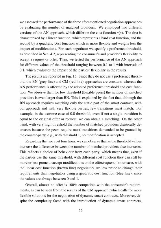
we assessed the performance of the three aforementioned negotiation approachesby evaluating the number of matched providers. We employed two differentversions of the AN approach, which differ on the cost function c(s). The first ischaracterized by a linear function, which represents a hard cost function, and thesecond by a quadratic cost function which is more flexible and weighs less theimpact of modifications. For each negotiator we specify a preference threshold,as described in Sec. 4.2, representing the consumer’s and provider’s flexibility toaccept a request or offer. Then, we tested the performance of the AN approachfor different values of the threshold ranging between 0.1 to 1 with intervals of0.1, which evaluates the impact of the parties’ flexibility in the results.
The results are reported in Fig. 15. Since they do not use a preference thresh-old, the BN (grey line) and CM (red line) approaches are constant, whereas theAN performance is affected by the adopted preference threshold and cost func-tion. We observe that, for low threshold (flexible peers) the number of matchedproviders is even larger than BN. This is explained by the fact that, although theBN approach requires matching only the static part of the smart contract, withour approach and with very flexible parties, few transitions must match. Forexample, in the extreme case of 0.0 threshold, even if not a single transition isequal to the original offer or request, we can obtain a matching. On the otherhand, with very high threshold the number of matched providers drastically de-creases because the peers require most transitions demanded to be granted bythe counter-party, e.g., with threshold 1, no modification is accepted.
Regarding the two cost functions, we can observe that as the threshold valuesincrease the difference between the number of matched providers also increases.This reflects a choice of behaviour from each party, which means that, even ifthe parties use the same threshold, with different cost function they can still bemore or less prone to accept modifications on the offer/request. In our case, withthe linear cost function (brown line) negotiators are less prone to change theirrequirements than negotiators using a quadratic cost function (blue line), sincethe values are always between 0 and 1.
Overall, almost no offer is 100% compatible with the consumer’s require-ments, as can be seen from the results of the CM approach, which calls for moreflexible solutions for the negotiation of dynamic smart contracts. Moreover, de-spite the complexity faced with the introduction of dynamic smart contracts,
56

CM
BN
0 0.2 0.4 0.6 0.8 10
20
40
60
80
100
Thresholds
Avg
Mat
ched
Prov
ider
s
AN (c(s))quadraticlinear
Figure 15: Negotiation results of the BN, CM and AN approaches.
the average number of providers matched with our approach is relatively closeto providers matched by the BN approach, which only considers the static partof the agreement. Therefore, we can conclude that these results emphasise theeffectiveness of our autonomic negotiation approach.
57

Chapter 5
Scheduling Latency-SensitiveServices in Edge Computing
The lack of solutions for scheduling of latency sensitive applications, we noticedduring the study of possible scenarios suitable for the application of SLAC, mo-tivated the work described in this chapter, also stated in third research questionof the introduction.
Essentially, the main factors that lead us to this work are two: we thought thatthe dynamism characterizing latency-sensitive applications could make this typeof services a very good use case for putting SLAC at work; we could not find anywork on scheduling this kind of applications in a Edge scenario which representsthe most suitable deployment platform for latency-sensitive applications.
The main contributions of this chapter are:
1. A novel Edge scheduling framework for latency-sensitive services, that islatency, bandwidth and resource aware.
2. The analysis of performance of different deployment solutions, namelyCloud, CDN and Edge, for latency-sensitive services, which shows theadvantages of Edge computing in this context.
3. The evaluation of the proposed scheduling framework in comparison to asolution for latency-sensitive services in Cloud, which shows the benefitsof using an algorithm specifically devised for this architecture.
58

Experimental results show that Edge-based deployment solutions actuallyguarantee lower end-to-end latency compared with the alternatives Cloud andCDN. However, we also proved that, to really exploit the advantages of Edge,specific scheduling algorithms need to be adopted, which take into account spe-cific infrastructure related characteristic such as latency, bandwidth and resourceavailability.
The structure of this chapter is organised a follows. In the next section,we present the related works; in Sec. 5.1 we provide a motivating example dis-cussing the benefit of Edge-based deployment approach for latency sensitiveapplications such as a live video streaming service; in Sec. 5.2 we present thescheduling approach we devised; in Sec. 5.3 we describe the experimental setupused for the evaluation of our approach together with the results we obtained.
5.1 Motivating Example
To better motivate the research question we are dealing with in this chapter, weconsider a simple scenario, based on live video streaming services, that will beused also for the experimental analysis.
Live video streaming services allow to stream a video recorded by any de-vice equipped with camera in nearly real-time to a large number of mobile ordesktop audience globally. Currently, due to the advances in networking tech-nologies these services are becoming very popular and attracting the attentionof big companies such as Twitter, Facebook and Google who developed theirown live video streaming services. To better understand what are the challengesunderlying this kind of services, let us first quickly describe the live streamingservice workflow depicted in Fig. 16.
The first step is the encoding of input video in a high quality stream, usingeither local camera encoder or an external one installed in remote server. Af-terwards, the encoded video is given as an input to the transcoding operationswhich create streams in different resolutions and bitrates on the fly. This pro-cess is fundamental in order to reach a very broad audience. Indeed, creatingnew streams at various bitrates and resolution allows an adaptive distribution ofthe video content according to the device used to access the stream and band-width condition, guaranteeing a high quality of experience for many users. The
59

multiple streams in output from the transcoding process are then processed by amedia server responsible of packaging the video streams, according to the spec-ifications (e.g., chunk length, codecs and container) defined by the streamingprotocols (e.g., HLS, HDS, etc.) supported. The video chunks are then readyto be directly delivered to end users according to their location, bandwidth andstreaming protocol implemented by the media player they use, or first dissemi-nated on multiple servers closer to them.
Although the service workflow may look quite simple, all the steps describedare characterized by some critical issues that will affect the overall user engage-ment to the video stream. Factors impacting user engagement, as reported in[23], are the join time (i.e., the duration from the player initiates a connection toa video server till the time the play starts), the buffering ratio (i.e., percentageof the total streaming session time spent in buffering) and the video quality. Allthese metrics are directly affected by the transcoding and distribution steps ofthe streaming workflow, which strictly rely on the service deployment solutionadopted. Currently, streaming service providers adopt Cloud-based deploymentsolutions in order to face the high and quickly changing processing resource andbandwidth requirements. In the simplest Cloud-based architecture, as depictedin Fig. 18, the incoming video stream is usually encoded in a high quality videolocally and then uploaded to a cloud server for transcoding and packaging oper-ations.
In this way, exploiting the elasticity provided by the Cloud infrastructure,it is possible to dynamically manage the resource needs according to the cur-rent service load. However, this deployment solution is not the best approachto maintain a low buffering ratio and a high video quality. Whereas extensivecomputation required for the transcoding operations can be managed accordingto the current needs, the best effort delivery of the packets from a cloud serverto final users can still incur downgraded video experience. Indeed, the path be-tween users and the stream origin server in the Cloud usually involves multiplehops and then the probability of experiencing link congestion along the route ishigh. Congested links incur a low throughput and high packet loss and delayjitter, introducing high network delay and discontinuous packet delivery rate,causing a drop in the video quality.
To face these network issues, the most widely adopted solution currently is
60

Figure 16: Live video streaming workflow.
content delivery networks (CDNs) for the distribution of streaming contents. Inthis scenario, as depicted in Fig. 19, all the transcoding and packaging opera-tions are still executed on the Cloud, but the media contents are then distributedover a network of cache servers located closer to end users. In this way, userrequests are automatically directed to the closest cache node, which forward tothe Cloud only the requests whose content is not already available on that node.Therefore, an improved bandwidth consumption is provided and then the risk ofnetwork congestion is lower, reducing the buffering ratio while increasing thevideo quality experienced.
Nevertheless, CDNs have originally been designed for the distribution ofstatic contents and adopting them for the distribution of dynamic contents aslive video streams is not straightforward. The main issues arise from the volumeand requirements of live video streaming users. Indeed video content accountsfor 70% of whole Internet traffic [8], which is much higher compared to the traf-fic generated by other web-applications. Moreover users demand high qualityvideo, instant start up times and low buffering ratio, requirements which bringto high demand of bandwidth, whereas CDN aims to minimize costs and theymay not meet these high-demanding requirements. Finally, a CDN-based dis-tribution can easily become too costly as the number of streams and viewersincreases, due to the high bandwidth costs.
61

Figure 17: Edge-based platform for live video streaming services.
To face the issues of the approaches described above, the set of innovativetechnologies introduced by the Edge paradigm may provide the solution needed.Indeed, Edge solutions can be used to tackle various challenges currently facedby media and video streaming applications in order to improve the service qual-ity experienced by end users. A possible Edge-based video streaming platformis depicted in Fig. 17.
With Edge computing, incoming video is first encoded in high quality, eitherwith the camera encoder or with an encoder installed in the closest edge node,and then distributed over a set of edge nodes responsible for both video transcod-ing and content distribution. In this way, video will be encoded on the fly anddelivered to the viewer, removing all the delay introduced by fetching videocontent from central Cloud. We also assume that there are different transcoderconfigurations related to different device type (e.g., smartphone, tablet, IPTV,etc.) that will transcode the input video in multiple streams suitable for a givenspecific device. Therefore, even though edge nodes cannot provide the samecomputing power of cloud nodes, distribution of individual encoders, each for aspecific type of device, makes computational requirements of transcoding oper-
62

ation suitable for edge nodes.Overall, the main advantages of this approach are the reduction of end-to-
end latency and bandwidth consumption. Indeed, strict proximity of end usersto the nodes delivering video content reduces delay due to both a shorter physicaldistance and a reduced probability to face network congestion, since the numberof links and hops along the route is smaller compared to the Cloud- and CDN-based approaches. Moreover, bringing transcoding process to the Edge furthercontribute to lower delay since video is processed and packaged on that nodewithout the need of fetching missing content from an origin server in a clouddata-center.
5.2 A Scheduling Framework for Edge Computing
Before describing the scheduling framework we devised, we provide a generaloverview of the system we considered, while reminding that, in the consideredscenario, the Edge infrastructure is essentially an extension of a Cloud infras-tructure with a set of edge nodes deployed at the edge of the network.
Moreover, these edge nodes are geographically distributed according to themodel described in [33], in proximity of multi Radio Access Technology (RAT)base stations (BSs), which provide access to the core network to both user equip-ment and edge nodes. We assumed that each node is a micro data-center that,
Figure 18: Cloud-based solution for live streaming services.
63

Figure 19: Delivery networks for streaming media contents.
leveraging on virtualization technologies, grants access to its resources by meansof virtual machines (VMs). Therefore, each node defines a virtualized environ-ment that allows the deployment of a service instance within an individual VM.Since different services have different computing requirements, in this scenariowe assumed that a node can provide different type of VMs. To provide Edgeservices, the application service provider (ASP) requests to a provider the in-stantiation of a service in a VM compatible with the service requirements. Sincein our work we considered only latency-sensitive services, the main service re-quirement the provider has to guarantee is the service response time, that is,the time elapsed from a user sending a request and receiving a reply. In thisscenario, the network delay and the processing time are the main factors thataffect this metric. The former refers to time necessary to a user request fromthe user device to reach the edge node of the service and it is determined byuser-node physical distance, queuing and processing delay of each hop in thenetwork route and the route’s available bandwidth. The request processing timeis strictly related to the VM and service specifications and refers to the time toelaborate a request. In this context with different VM and service specifications,further analysis of computing performance is needed to select a VM type thatcan optimize this metric.
Therefore, for the scenario described above, we designed a scheduling frame-work, summarized in Fig. 20, that takes into account network, bandwidth andcomputing capabilities of the Edge infrastructure to maximize the service qual-
64
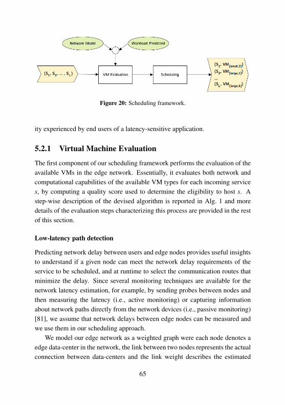
Figure 20: Scheduling framework.
ity experienced by end users of a latency-sensitive application.
5.2.1 Virtual Machine Evaluation
The first component of our scheduling framework performs the evaluation of theavailable VMs in the edge network. Essentially, it evaluates both network andcomputational capabilities of the available VM types for each incoming services, by computing a quality score used to determine the eligibility to host s. Astep-wise description of the devised algorithm is reported in Alg. 1 and moredetails of the evaluation steps characterizing this process are provided in the restof this section.
Low-latency path detection
Predicting network delay between users and edge nodes provides useful insightsto understand if a given node can meet the network delay requirements of theservice to be scheduled, and at runtime to select the communication routes thatminimize the delay. Since several monitoring techniques are available for thenetwork latency estimation, for example, by sending probes between nodes andthen measuring the latency (i.e., active monitoring) or capturing informationabout network paths directly from the network devices (i.e., passive monitoring)[81], we assume that network delays between edge nodes can be measured andwe use them in our scheduling approach.
We model our edge network as a weighted graph were each node denotes aedge data-center in the network, the link between two nodes represents the actualconnection between data-centers and the link weight describes the estimated
65
network latency between them. We assume, then, that each user connects tothe closest BS and we group together users connecting to the same BS (line2). Therefore, for each user group g we detect the lowest latency path from gto a every node n applying the Dijkstra algorithm on the graph modelling ournetwork, considering as source node the node representing the edge data-centerco-located with the BS of the group (line 5). This set of low latency paths willbe used for the VM evaluation process described in the next section.
Network and resource evaluation
To identify the most suitable VM to a given service, we defined an evaluationprocess which computes, for each type of VM, a quality score qv combiningconnectivity qn,l , bandwidth qn,bw and resource qv,res scores.
The connectivity score qn,l ∈ [0,1] assesses the quality of the connectivity ofa VM v by evaluating the quality of the network routes connecting user groupsto the node n running v. The input data for this process is the set of low-latencypaths computed in Sec. 5.2.1. Therefore, for each network path connecting agiven user group g to the n, we evaluate the delay according to the network delayrequirements by computing a quality score qn,l,g ∈ [0,1] using a utility functionpreviously defined by the provider (line 7). The output of this path-based eval-uation process is a set of quality scores {qn,l,g1 ,qn,l,g2 , . . . ,qn,l,gn}, which willbe used to compute the connectivity final score ql,n as the mean value of thesescores weighted by the number of users belonging to each group (line 9).
The bandwidth score qn,bw ∈ [0,1] assesses the available bandwidth of thenode n running the given VM v. The available bandwidth on paths connectingthe users to n represents one of the main factors affecting the overall servicequality, as already motivated in Sec. 5.1, therefore information about the nodecapacity can improve the service scheduling. We compute a per path bandwidthscore qn,bw,g ∈ [0,1], assessing the quality of the bandwidth of each low latencyroute in input (line 8). Similarly to the latency evaluation process, we computethe final bandwidth quality score qn,bw as the average of the single path qualityscores qn,bw,gi weighted by the number of users in each group (line 10).
The VM resource evaluation is carried out by measuring the service load thata given VM type v can handle and the expected overall service load. Indeed, forlatency sensitive applications, underestimating the computational resource nec-
66

essary for executing the service may increase considerably the service process-ing time and the overall end-to-end response time. Our approach, then, evaluatesthe computational resources of a VM v computing a score qv,res ∈ [0,1] by meansof a utility function defined by the provider, comparing the number of user re-quests that v can handle w with the overall number of requests expected w (line12).
Finally, the overall quality score of a given VM type qv ∈ [0,1] is calculatedas the harmonic mean of connectivity, bandwidth and resource quality scores(line 13). Despite the fact that the harmonic mean behaves as the arithmeticmean by giving equal weight to both scores when they are similar, it favours thesmaller value when the gap between them increases. This ensures that VMs witha very high and a very low score are penalized, which emphasises the need ofsufficient network and computational resources. The evaluation output is the setQ = {qv1 , . . . ,qvk} of VM type quality scores that will be used by the schedulerfor service deployment (line 14).
5.2.2 Scheduling Approach
The second component of the framework we devised is the scheduler, that is incharge to select, for each service s ∈ S received as input, the VM type v ∈ Vwhich most likely will fulfil the established latency requirements.
We compute for each v a quality score qs,v using the approach describedin Sec. 5.2.1, which is based on the VM computing specifications and the net-work capabilities of the node hosting that VM. Then, the service instances arescheduled to maximize the overall quality of the selected VMs, guaranteeing anenhanced service quality to end users.
We model the optimisation problem as a binary integer linear programmingproblem as reported in formulation below. Binary variables xs,v model the place-ment of a service s on the VM type v, and assume value 1 only when the serviceis actually scheduled on that VM. The coefficients are the VM quality scorescomputed by the VM evaluation process previously described, which measuresthe suitability of the VM type v in hosting the service s. The cost function (I)aims to maximize the quality of the final scheduling, assigning at each service sthe most suitable VM.
67

maximizex ∑
s∈S∑
v∈Vqs,vxs,v (I)
s. to ∑v∈V
xs,v = 1 ∀s (II)
∑s∈S
xs,v ≤ kv ∀v ∈ Vn (III)
where
xs,v =
{1 if s is scheduled on v0 otherwise
Furthermore, we assume that each service has to be scheduled on a singleVM, as expressed in (II), and that the number of times a VM type is assigned tonew services cannot exceed the number kv of available VM instances, defined in(III).
5.3 Validation of our Approach
In this section we present the experiments we carried out to analyse the effec-tiveness of the proposed framework in terms of service quality experienced bythe end users.
5.3.1 Experimental Setup
The experiments evaluate how different deployment solutions affect the livevideo streaming service time experienced by end users and analyse the impacton its components, namely the network delay and the request processing time,with different number of users joining the video stream in input. A compre-hensive description of the different scenarios considered in our experiments isprovided in Sec. 5.3.2. We simulated these scenarios using the EdgeCloudSimsimulator [64]. This simulator extends the CloudSim toolkit [11] providing extrafunctionalities granting the modelling of networking resources and edge nodes,allowing a accurate simulation of real edge infrastructures. The results obtained,not only show the benefit of the Edge platform in terms service time, but denotethe need of a Edge-specific scheduling solution to obtain optimal results.
68

Algorithm 1: Latency-Sensitive SchedulingData: Service s to be scheduledData: Latency constraint t requested by the service providerData: Users’ locations U = {u1,u2, . . . ,um}Data: Nodes N = {n1,n2, . . . ,nk}Data: Nodes’ location L = {l1, l2, . . . , lk}Data: VM types V M = {vi,1,vi,2, . . . ,vi,q,∀i ∈ N}Data: Array Q of quality scores for each VM v ∈V MResult: The vms scheduled for s.
1 begin2 Define a set of users’ groups G = {gi, |u j− li|< ε ∀u j ∈U,∀li ∈ L};3 forall the n ∈ N do4 forall the g ∈ G do5 Estimate the network path pg,n with the lowest latency tg,n between g
and n;6 Estimate the available bandwidth bwg,n between users in g and the
node n and the required bandwidth bwg on pg,n;7 Compute the latency score qn,l,g = LatencyScore(t, tg,n);8 Compute the bandwidth score
qn,bw,g = BandwidthScore(bwg, bwg,n);
9 qn,l =∑
ni=1 |gi|qn,l,gi∑
ni=1 |gi| ;
10 qn,bw =∑
ni=1 |gi|qn,bw,gi
∑ni=1 |gi| ;
11 forall the v ∈ n do12 qv,res = ComputingScore(w, wv);13 Compute the qv quality score Q[qv]= 3
1qv,res
+ 1qn,l
+ 1qn,bw
14 vms = Scheduler(Q);15 return vms;
69

5.3.2 Scenarios
We defined a set of simulation scenarios where we analysed the impact of dif-ferent deployment solutions and scheduling policies on the service quality ex-perienced by end users, in the context of live video streaming services. In theremainder of this section we provide a detailed presentation of the different net-work designs and scheduling approaches in each scenario devised.
Cloud. We consider a centralized deployment solution where both video pro-cessing and content distribution processes are carried out on a cloud data center.Essentially, given an incoming video to be streamed, all the encoding/transcodingoperations are executed on a cloud data center. User requests to access the livestream are also directly forwarded to the cloud server responsible of stream dis-tribution.
We modelled cloud resources as set of infinite VM instances whose specifi-cations are taken from the Amazon m2.4xlarge and are reported in Tab. 9. Theusers-data center connection has been defined as a single link, whose capacityhas been fixed at 1000 Mbps, representing the aggregation of single links con-necting user access BSs to the cloud. We defined also a communication delayδu,c = 0.09, which models the delay related to the queuing and processing op-erations and the physical distance characterizing the network route between theuser u and the cloud data center c. This value has been estimated by averaginglatency of ICMP requests between hosts in Europe and the Amazon Web Serviceinstances in the same time zone.
Content delivery network (CDN). We defined a two-tier network architec-ture, characterized by an origin server in a massive cloud data-center and 10 geo-graphically distributed replica servers. In this scenario the encoding/transcodingoperations are executed in the cloud servers, while the content is distributedamong the replica nodes. Users are randomly distributed in proximity of allreplica nodes and the content distribution follows the schema designed in [51].Therefore, a user request is first redirected to the closest replica server and then,if the content is already cached there, it is directly returned. Otherwise, therequest is forwarded to the cloud server to fetch the content.
In this scenario origin and replica servers have different purposes and thendifferent hardware configurations. We assumed that CDN (replica) nodes are
70

Algorithm 2: FIXED provisioning algorithmData: Set of QoS requirements offered by the ASP: S = {QoS(x),x≥ 0}Data: Estimated mean inter-arrival times: 1
λ
Data: Estimated mean requests durations: 1µ
Result: Number of VMs to acquire: V1 begin2 calculate the smallest number of V such that λ
V µ ≤ 1;
3 t = min(QoS(x)),QoS(x) ∈ S;4 P(w(ri)> t) = 1;5 ρ = λ
V µ ;
6 while P(w(ri)> t)> p do7 calculate ΠW =
(V ρ)V
V ! ((1−ρ)∑V−1n=0
(V ρ)n
n! +(V ρ)V
V ! )(−1);8 calculate P(w(ri)> t) = ΠW e(−V µ(1−ρ))t
;9 if P(w(ri)> t)> p then
10 V =V +1
11 return V
small data centers located only in strategic points, such as ISP point of pres-ences (PoPs) or at internet exchange points (IXPs). CDN servers’ access band-widths are distributed as a Pareto distribution with mean value µ = 500 and eachconnection user-server is characterized by communication delay δv,s = 0.013s.Similar to the Cloud scenario, δv,s measures the expected delay due to the phys-ical characteristics (e.g., number of hops and distance) of the route between thehost and the closest CDN server. We modelled the connection between CDNservers and the cloud origin server as a high capacity link with an average band-width of µ = 750Mbps, since we assumed that they are directly connected tothe ISP backbone. We also defined a link communication delay as δe,c = 0.03s,modelling the delay along the path from the CDN and the origin server basedon the number of hops and the physical distance between them. Moreover, sincethe main purpose of CDN networks is to deliver content, the VM instances usedin this scenario are storage optimized. Therefore we used the Amazon i3.largespecifications, as reported in Tab. 9.
71

Edge. In this scenario, according to the Edge-based deployment solution de-scribed in Sec. 5.1 the service is entirely deployed on the edge nodes. Therefore,both encoding/transcoding and distribution operations are executed on the edgenodes, whereas the Cloud has only management functionalities.
The designed network infrastructure is composed of 20 edge nodes, each co-locate with a BS. The computing power of each node is rather limited. Each nodeprovides 2 types of VMs, namely the Amazon m1.large and m1.xlarge instancetypes, but, due to limited physical resources, only 10 instances that can actuallyinstantiated on each node. The access bandwidth of each edge node has beenmodelled instead as a Pareto distribution with average value µ = 375Mbps. Inthis scenario we also assume that the distance between edge nodes is small, in theorder of 20km, allowing the deployment of high speed inter-node connectionsthrough either dedicated links or single-hop connections. Thus, we modelledthe inter-node bandwidth whose capacity is distributed also as a Pareto distri-bution with mean value µ = 400Mbps. The communication delay between thenodes i and j has been modelled, instead, by mean of a uniform distributionU[0.006,0.009].
In this scenario, we assume that users can access the stream video with 3different type of devices, namely smartphone, laptop and tablet. Therefore, ac-cording to the Edge-based service deployment described in Sec. 5.1, we assumethat 3 different and lightweight streaming engines (i.e., packages responsible ofencoding/transcoding operations and content distribution) have to be deployed,each one for a specific device. Each instance is responsible for transcoding thevideo input into multiple bit rates and resolutions suitable for a given device.We used two different approaches for the scheduling of the instances, that isCloud-based and Edge-based, described below.
In the Edge-based scenario, we schedule the services using the approach pre-sented in Sec. 5.2.2. For the VM evaluation process, described in Sec. 5.2.1, wedefined three utility functions as in Eq. 5.1, Eq. 5.2 and Eq. 5.3 for the evaluationof the network delay, the available bandwidth and VM resource respectively.
uv,δ(δg,v, δ) = S(
1−δg,v
δ
)(5.1)
72

uv,B(Bg,v, B) = S(
Bg,v
B−1)
(5.2)
uv,RPS(RPSv,W ) = S(
RPSv
W−1)
(5.3)
For the evaluation of the network route delay between a user group g and a VMv, we compute a utility score using a sigmoid function S, that takes in inputthe route delay δg,v and the delay requirement δ = 50ms. Therefore, the utilityfunction in Eq. 5.1 evaluates the margin between the actual delay δg,v and therequirements δ returning a score as close to 1 as the current delay is significantlylower than the requirements. Otherwise, low values close to 0 are returned.Bandwidth and resource evaluation follow the same approach defined for thedelay evaluation. Essentially, given the predicted available bandwidth Bg,v onthe network route from g to v the utility function returns a value as close to 1as the value of Bg,v is higher then the needed bandwidth B due to the numberof users in g. The resource evaluation is achieved, instead, by comparing thecomputing capability of v expressed in terms of request per second RPS with theexpected number of requests W generated by the expected workload. Finally,the scheduling is defined by the scheduling approach in Sec. 5.2.2.
In the Cloud-based approach, instead, we adopted a Cloud scheduling ap-proach [26] that estimates the number of streaming engines instances neededto minimize the user waiting time. This approach aims to minimize the pro-cessing time deploying a number of instances based on the expected workload.The Alg. 2 shows the pseudo-code of their approach. They define a M/M/V5
queuing model to determine the number of VMs to be instantiated in advanceto guarantee a user waiting time compliant with the requirements. Three inputsare required: (i) the estimated mean inter-arrival time of requests 1/λ, (ii) theestimated mean duration of requests 1/µ and (iii) and the target probability pthat a request has to wait more than its QoS requirement. The first step of thealgorithm (line 2) computes the initial number of VMs V , such that the systemutilization is lower than one. Then, the smallest waiting time t to be guaranteedby the service provider is determined (line 3). Afterwards, the algorithm updatesthe number of VMs to be instantiated until the probability that a new service re-quest w(ri) has to wait more than t (P(w(ri) > t)) is lower than the thresholddefined by p. Finally, for each streaming engine type the number of replica is
73
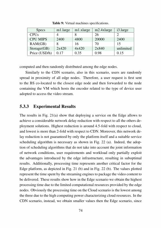
Table 9: Virtual machines specifications.
Specs m1.large m1.xlarge m2.4xlarge i3.largeCPUs 4 8 26 2CPU MIPS 2400 4800 20000 2400RAM(GB) 8 16 70 15Storage(GB) 2x420 4x420 2x840 unlimitedPrice (USD/h) 0.17 0.35 0.98 0.15
computed and then randomly distributed among the edge nodes.Similarly to the CDN scenario, also in this scenario, users are randomly
spread in proximity of all edge nodes. Therefore, a user request is first sentto the BS co-located to the closest edge node and then forwarded to the nodecontaining the VM which hosts the encoder related to the type of device useradopted to access the video stream.
5.3.3 Experimental Results
The results in Fig. 21(a) show that deploying a service on the Edge allows toachieve a considerable network delay reduction with respect to all the others de-ployment solutions. Highest reduction is around 4.5-fold with respect to cloud,and lowest is more than 2-fold with respect to CDN. Moreover, this network de-lay reduction is not guaranteed by only the platform itself and a suitable servicescheduling algorithm is necessary as shown in Fig. 22 (a). Indeed, the adop-tion of scheduling algorithms that do not take into account the joint informationof network conditions, user requirements and workload only partially exploitthe advantages introduced by the edge infrastructure, resulting in suboptimalresults. Additionally, processing time represents another critical factor for theEdge platform, as depicted in Fig. 21 (b) and in Fig. 22 (b). The values plottedrepresent the time spent by the streaming engines to package the video content tobe delivered. These results show how in the Edge scenario we obtain the highestprocessing time due to the limited computational resources provided by the edgenodes. Obviously the processing time on the Cloud scenario is the lowest amongthe three due to the high computing power characterizing cloud resources. In theCDN scenario, instead, we obtain smaller values then the Edge scenario, since
74
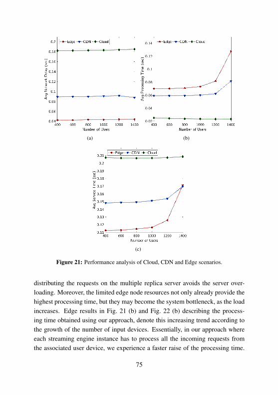
(a) (b)
(c)
Figure 21: Performance analysis of Cloud, CDN and Edge scenarios.
distributing the requests on the multiple replica server avoids the server over-loading. Moreover, the limited edge node resources not only already provide thehighest processing time, but they may become the system bottleneck, as the loadincreases. Edge results in Fig. 21 (b) and Fig. 22 (b) describing the process-ing time obtained using our approach, denote this increasing trend according tothe growth of the number of input devices. Essentially, in our approach whereeach streaming engine instance has to process all the incoming requests fromthe associated user device, we experience a faster raise of the processing time.
75

(a) (b)
(c)
Figure 22: Performance comparison of Cloud and Edge scheduling approaches.
Therefore, to reduce this high processing time in the Edge scenario, provider canhorizontally/vertically scale the servers in the edge data centers or create newedge data centers in the overloaded locations. Results in Fig. 22 (b) confirm thisassumption showing that predicting in advance, the number of VM instances foreach streaming engine enhances the performance, reducing the average process-ing time needed to elaborate each user request. However, due to the significantnetwork delay reduction provided by the edge-based solution, higher process-
76

ing time does not affect the overall service time, if the processing capacity ofthe servers is not saturated, as depicted in Fig. 21 (c) and in Fig. 22 (c). Forvery high number of users, instead, higher processing time of Edge introducesa system bottleneck that considerably affects the final service time experiencedby end users (Fig. 22 (c)). Nevertheless, results in Fig. 22 (c) confirm the needfor scheduling solutions that take Edge specific features into account and for aninfrastructure with processing capacity compatible with number of users in theedge data centers to obtain good performance in Edge scenario.
77

Chapter 6
Related Works
In the area of Cloud Computing many works have already been carried out forthe development of frameworks for the management of service quality through-out the whole service life-cycle [5, 6, 15, 17, 77]. However, they are mainlyfocused on the definition of theoretical technical frameworks without providingany real implementation of the methods actually responsible of SLA manage-ment tasks.
Nonetheless, many studies have been accomplished for the development ofpoint wise solutions dealing with the challenges introduced by each stage in theservice life-cycle.
In the remainder of this section we provide a comprehensive overview of themost relevant works related to SLA specification languages, negotiation and ananalysis of the solutions currently adopted for service scheduling in Cloud.
6.1 SLA Definition Languages
To provide an overview of the most important languages currently adopted, weextend the study of [40] to cover additional languages and new aspects of thealready evaluated ones. Below we briefly describe the evaluation criteria. Theresults of our evaluations are summarised in Tab. 10 and show the advantageof SLAC over other formalisms. Important components of the Cloud domainlike dynamicity, multi-party agreements, and brokerage are supported only by
78

SLAC, and the supporting software framework allows an easy deployment ofSLAC SLAs in a wide-range of real-world scenarios.
For our assessment, we consider the following formalisms: WSLA [37],WS-Agreement [3], WSOL [66], RBSLA [50], Linked USDL (LUA for short)[52], SLALOM [16], SLAng [63], SLA* [38], CSLA[58] and, of course, SLAC.We evaluate them by first considering General features of the languages and thenassessing their impact on the different phases of SLAs lifecycle. In the table, weuse yes for indicating that the feature is fully supported, X for indicatingthat the feature is partially supported, and 7 for indicating that the feature is notsupported.
General considers the evaluation of different aspects that we list below:
• Cloud Domain considers whether a SLA language has been specificallydesigned for Cloud;
• Service Models evaluates whether all service models (including specificvocabularies) are directly supported or, in some cases, extensions are needed;
• Formalisation refers to the level of formality in the definition of syntaxand semantics of the language;
• Dynamicity considers the capacity to express possible changes of the termsof agreement at runtime.
• Confidence or Fuzziness is the capacity to deal with QoS uncertainty, withconfidence defining the percentage of compliance of clauses, and fuzzi-ness referring to an acceptable interval around the threshold of a metric;Reusability refers to the possibility of reusing constructs defined in a tem-plate or in a SLA across different SLAs;
• Composability is the ability to express composite SLAs;
• Extensibility evaluates whether the language terms and metrics can be ex-tended;
• All parties considers whether it is possible to describe all parties involvedin the service provision and in all actions (monitoring, verification, provi-sion, etc.);
79

• Price Model is the level of coverage of price schemes and of computationmodel;
• Consistency check considers whether consistency of SLAs is verified; wewrite X if only syntactic checks are offered, if also semantic aspectsare considered, and 7 if no check is performed.
Definition, Discovery and Negotiation considers the possibility of using:
• Editor for writing SLAs, they can be generic (X), domain-specific( ) orabsent (7);
• Broker may have different levels of support when taking decisions;
• Metric Definition refers to the possibility offered for defining quality met-rics;
• Alternatives evaluates the ability to specify alternative levels of service;
• Soft Constraints is concerned with the use of soft-constraints to addressover-constrained requirements;
• Matchmaking Metric enables the specification of how to match equivalentmetrics or metric units;
• Negotiability is the ability to indicate how, and to which extent, qualityterms are negotiable.
Deployment and Monitoring considers the offering of:
• Metric Schedule indicates how often the terms of agreements are mea-sured;
• Metric Provider indicates the possibility of specifying the party responsi-ble for monitoring each term of agreement;
• Automatic Deployer refers to the provision of tools for automatic deploy-ment of the service;
• Integrated Monitoring is concerned with the capacity to automaticallyconfigure the monitoring system relying on the SLA specification.
80

Billing and Penalty Enforcement considers the presence of:
• Penalties and Rewards to be enforced under specified conditions. In thiscase, stands for fine-grain support (at the level of service level objec-tives), X for coarse-grain, and 7 for no support.
• Actions triggered by contracts violations;
• Conditions Evaluator refers to the possibility of specifying the party incharge of auditing each term;
• Assessment Scheduler specifies when each term is assessed.
Termination considers the
• Automatic Undeployment of the used resources.
81

Tabl
e10
:Eva
luat
ion
resu
ltsof
SLA
lang
uage
sPh
ase
Cri
teri
aW
SLA
WS-
AW
SOL
RB
SLA
LU
ASL
AL
OM
SLA
ngSL
A*
CSL
ASL
AC
Clo
udD
omai
n7
77
77
77
Serv
ice
Mod
els
XX
XX
XX
XX
X
Form
alis
atio
n7
77
XX
XX
Dyn
amic
ity7
77
X7
77
77
Con
fiden
ceor
Fuzz
ines
s7
77
77
77
77
Reu
sabi
lity
77
7
Com
posa
bilit
y7
X7
77
7X
Ext
ensi
bilit
y7
77
77
All
Part
ies
77
77
77
77
7
Pric
eM
odel
77
77
7X
X
General
Con
sist
ency
chec
kX
XX
X7
Edi
tor
XX
XX
X7
7
Bro
ker
7X
77
77
77
7
Met
ric
Defi
nitio
n7
77
77
7
Alte
rnat
ives
XX
XX
77
77
7
Soft
Con
stra
ints
77
77
77
77
Mat
chm
akin
gM
etri
c7
77
77
77
7
Disc./Nego.Definition
Neg
otia
bilit
y7
X7
77
77
7
Met
ric
Sche
dule
77
7
Met
ric
Prov
ider
77
77
7
Aut
omat
icD
eplo
yer
77
77
X7
Mon.Deploy.
Inte
grat
eM
onito
ring
77
77
7
Pena
lties
7X
X
Rew
ards
77
X7
77
7
Act
ions
77
77
7
Con
ditio
nE
valu
ator
77
77
PenaltyEnfor.Billingand
Ass
essm
entS
ched
ule
XX
XX
77
7
Aut
omat
icU
ndep
loym
ent
77
77
77
7X
7
Ter.
82

6.2 SLA Negotiation
Still the in area of SLA management many works have been carried out for theautonomic negotiation of SLAs. Many of them are mainly based on the approachadopted for the negotiation of traditional contracts.
Indeed, they are mainly divided into: game theoretic models, heuristic andargumentation-based methods [36]. Here, we focus on heuristic approachessince, even for static contracts: (i) the game theoretic techniques assume thatnegotiators have full knowledge of peers’ preferences [36], which is not suitablefor Cloud due to the large number of participants, SLA terms and strategies [48];(ii) applying the argumentation-based approaches in automated negotiation forcloud is challenging [32] and few works actually employ it [12].
Heuristic approaches define protocols and strategies to look for good solu-tions, which do not necessarily correspond to the optimal one [36] or do satisfyall the requirements of the involved parties. They are based on counter-offergeneration where each party decides, according to some heuristic, to accept-reject the offer or to create counter-proposal. The core element of this approachis the agents’ decision-making process which defines the offer’s evaluation andthe counteroffer generation. Two mechanism are usually adopted for decision-making: trade-off and concession. Essentially, the trade-off mechanism (usedin [18, 25, 78, 85]) defines counterproposals similar to the offer in terms ofnegotiator’s utility, where multiple negotiation terms are traded-off to fit bet-ter the opponent’s requirements [27]. The concession approach (for example,[13, 15, 27, 42, 80]) defines an offer generation mechanisms where, at each ne-gotiation step, the negotiator is willing to decrease the overall utility score ofthe agreement. This is done by decreasing the utility value of one or more termsusing different functions [48]: (i) time-dependent, which compute the next valueto be offered according the remaining negotiation time, (ii) resource-dependent,which consider the available resource during the negotiation process as main pa-rameter; and (iii) behaviour-dependent negotiation functions, which formulatethe new offer based on the previous opponent’s attitude [29].
Nevertheless, the trade-off and concession approaches cannot be used forsmart contracts, since applying them implies the execution of the counteroffergeneration mechanism in each possible state of the contract. Therefore, consid-
83

ering that both provider’s and consumer’s contract may have thousands of states,it becomes quickly infeasible.
6.3 Service Scheduling in Cloud
Also in the area related to service management, many works have been devel-oped which provide effective solutions for SLA-aware service deployment. Anexample is given by scheduling approaches which aim to optmize specific met-rics defined within the SLA.
For instance, many works have been developed for the scheduling of latency-sensitive services, that are characterized by more strict requirements on theservice-user latency.
In the area of distributed Cloud Papagianni et al. [49], proposed a frameworkfor an efficient mapping of VM user requests on the aggregate set of connectedclouds. They modelled the mapping problem as mixed integer programmingaiming to minimize the mapping costs and the number of hops among the VMs.Similarly, Aral et al. in [4] proposed a novel approach for the problem of map-ping virtual networks defined by the set of interconnected VMs (i.e., servicereplicas) on a real infrastructure in a distributed cloud. The solution devised isrelies on a topology based mapping approach and allocates the virtual networkdefined by the connections among service components on a cloud subnet whosetopology is isomorphic to the virtual one. They aim to reduce the network la-tency and optimize the bandwidth utilization. Still in the area of distributedCloud, in [39] the authors propose a novel approach to tackle the problem ofservice allocation in a federated Cloud environment for horizontally scalableservices. They defined a method which allocates service component replicastaking into account the maximum service requirements in terms of computing,networking and storage resources, a set of affinity and anti-affinity rules for de-ploying replica in the same node or subnet and the federated infrastructure costs.The allocation problem is then formulated as Mixed-Integer Linear Program-ming optimization problem and implemented, then, a heuristic solver that yieldsto near-optimal solutions in very short time. Pittaras et al. [54], instead, devel-oped an approach for efficient mapping of virtual networks onto a multi-domainnetwork substrate. They devised a semantic based approach for the mapping of
84

requests to real network subnets which minimizes the number of hops betweenselected nodes.
In the context of single Cloud providers, authors in [53, 82] developed ser-vice component placement methodologies that, similarly to the distributed sce-nario described before, optimize the service placement among servers in a singledata center minimizing the transfer time between service components. There-fore, also these approaches do not take into account users information whichwould make their application suitable for service scheduling in Edge. Authorsin [26], however, integrated user information in the service allocation method-ology they proposed. Indeed, they defined a provisioning algorithm based onqueuing theory to identify the number of VMs to be deployed in order to min-imize the user waiting time. However, this approach, intended for IaaS Cloud,only define the number of VMs needed to cope with the incoming load and isstill missing VM placement policies which would lead to sub-optimal results inthe case of Edge Computing.
In the area of Edge Computing, instead, no works are currently available,to the best of our knowledge, for service scheduling on edge nodes. Worksas [31, 44, 84] face edge computation offloading problem, that is the decisionof scheduling a task on mobile device or local/internet Cloud. Nevertheless,these works do not take into account the actual service scheduling between edgenodes.
In the area of Fog Computing, in [62], authors defined a scheduling approachfor the placement of service modules on fog nodes, focusing only on the opti-mization of response time among components, without taking into account theend-to-end service time. Aazam et al. in [1], instead, defined a resource esti-mation and pricing model for IoT, that estimates the amount of resources to beallocated for a given service, again without providing an solution for the selec-tion of a node where to allocate the service.
85

Chapter 7
Conclusions
Service quality in Cloud Computing has a considerable impact on the wholeservice life cycle. For example, given a set of functionally equivalent services,during the service acquisition phase, the consumer choice is mainly driven by thequality guarantees and terms of agreements they offer. Moreover, the violation,during the service execution, of previously agreed terms certainly affects thetrustworthiness of the consumers, that might ask the termination of the serviceexecution or decide to not renew the service provision once it is terminated.
Therefore, given the relevance of this area for the success of Cloud paradigm,many works have already been developed in the context of service quality spec-ification and management. However, in the devised solutions, the dynamismcharacterizing cloud services is not properly taken into account, even though itrepresents one of the distinguishing feature of these services.
We have proposed a framework which addresses service quality in the firstphases of the service life cycle, namely specification, negotiation and servicedeployment.
Specifically, for the service acquisition phase we have defined (i) SLAC, anovel specification language, that allows the definition of dynamic agreementsand (ii) a negotiation framework for the negotiation of the SLAs formulated withthe language we devised.
The SLAC language, presented in Chap. 3, introduces the definition of dy-namic SLAs allowing the modification of the quality of service terms at run time
86

when specific conditions are met, guaranteeing the adaptation of service perfor-mance. In this way, consumers and providers can associate service quality termvalues to specific service conditions, that can trigger automatic modification ofthose values when these conditions are reached. The presented experimental re-sults show the advantages of the dynamism offered by SLAC by evidencing areduction of agreements violations and thus of penalties as well as an increaseof the revenue for the provider.
Nevertheless, the adoption of this new specification language introduces newresearch challenges related to negotiation of the dynamic SLAs. Therefore, wedeveloped a novel framework (Chap. 4) for the negotiation of this new type ofagreements. It provides insights for the modification to be applied to serviceoffers and request to increase their compatibility and, consequently, to find afinal agreement between the parties.
To this aim, we proposed a formal framework for the specification of thisinteraction and a framework for the autonomous negotiation of smart contracts.The main steps of the solution we devised are checking of specification consis-tency, analysing the compatibility between offers and requests and elaboratingthe best possible agreement (if any). The outcome of the experimental evalua-tion shows that if the parties are willing to accept modifications of their initialproposals, the number of reached agreements improves considerably.
We also addressed the issues related to the scheduling of latency sensitiveapplications by defining a novel scheduling algorithm aiming at guaranteeingthe latency requirements in a Edge scenario.
The main factors that lead us to address this last challenge were the facts thatlatency-sensitive services are highly dynamic and thus a good test bed for theapplication of our service specification and negotiation framework; and currentlythere is no available solutions for addressing the scheduling problem in EdgeComputing, which represents the most suitable deployment solution for this typeof services.
Indeed, the latency characterizing Cloud platforms, cannot cope with thelatency requirements of these services, and thus the currently adopted cloud-based deployment solutions for these services turn out to not fully suitable. TheEdge paradigm, instead, extends the cloud infrastructure by adding computingresources in close proximity of end users and considerably reduces the end-to-
87

end latency. Moreover, the considered scenario represents a good use case forthe application of the solutions for service specification and negotiation; its highdynamism can benefit from the specification of dynamic requirements.
In Chap. 5, we defined a two stages score-based algorithm that, given a setof available Virtual Machines (VMs), first evaluates the eligibility of each VMtype to host a given service, assigning to each VM type a quality score, and thenschedules the services in order to maximize the total score of the chosen VMs,while guaranteeing higher service quality for end users. To evaluate our ap-proach we evaluated the impact of different deployment solution, namely Edge,CDN, and Cloud. The obtained results suggest that Edge is the best solutionin this context. Moreover, to validate our framework, we compared average re-sponse time, processing time and network delay experienced by the users of ourapproach with similar work by other researchers and showed that our solutionoffers much better performances.
7.1 Research Findings
Research Question 1How to properly describe service quality terms in Cloud Computing?
The needs of both cloud computing consumers and providers are service-driven, therefore when specific conditions are met, the service level objects needto be adapted accordingly. We propose a novel framework that allows the speci-fication of service level agreements that permits adapting the terms at run time,according to the conditions defined. The results we obtained demonstrate theadvantages of this autonomous approach in reducing services violations, and inguaranteeing enhanced quality of service for final user as well as higher revenuesfor the service provider.
Research Question 2How to negotiate SLAs for Cloud Computing with the new dynamic language?
One of the main challenges introduced by the use of dynamic SLAs is repre-sented by the negotiation process of offer/requests. Therefore we devised a ne-
88
gotiation framework, which autonomously executes the compatibility analysis ofthe parties’ proposals and seeks for modifications to be applied to both of them,to increase the compatibility and to eventually sign a final agreement. Experi-mental results show that with our approach, if parties are flexible in acceptingmodifications of their original proposals, a valid agreement can be reached.
Research Question 3How to enhance specific service quality
in distributed environments?
In this work we focused on Edge computing, a highly-distributed environ-ment, to enhance the quality latency sensitive services. Specifically, we definedan innovative scheduling algorithm that aims at maximizing service quality ex-perienced by end users and considers in the scheduling process the Edge comput-ing characteristics, such as, latency, bandwidth, and computational capabilities.The experimental results show that Edge-based deployment solutions offer goodperformance in terms of end-to-end latency. However, they also show that, foreffective exploitation, scheduling algorithms specifically devised for this plat-form are needed.
7.2 Limitations of our Study
In this section we summarize the main limitations of the work presented in thisthesis:
• Our final goal was to provide a framework for service quality managementin Cloud Computing focusing on the improvement of service quality spec-ification and on the development of novel techniques for service manage-ment. However, while we provided a comprehensive framework for SLAspecification and negotiation, we addressed only partially the managementphase. Indeed, we developed a solution for the initial deployment of theservices in Edge that does not consider the possible dynamic requirementsexpressed with SLAC in the decision process.
• The SLAC language we devised, defines a formalism for enhanced spec-
89

ifications, however it introduces new challenges in service discovery, ne-gotiation, scheduling and management processes that are only partiallyaddressed in this thesis. We mainly focused on the discovery and negotia-tion processes, whereas the analysis on how scheduling and managementtasks are affected by dynamic SLAs has not been carried out yet.
• The decision model devised in the negotiation framework does not allowparties to define a customized policy to be used during the negotiationprocess. Currently, the process is only based on the compatibility of SLAstates and transitions and it does not give the possibilities to the partiesto weight differently the states and the transitions during compatibilityanalysis. Moreover, costs and revenues of states and transitions are notconsidered in the decision model.
• The service scheduling solution we developed is only responsible for theinitial placement of service instances on edge nodes and does not provide arun time support for the service management during the service provision.
7.3 Future Works
In the previous section we outlined some limitations of our work which auto-matically suggest new challenges and further research topics:
• The scheduling approach we developed does not take into account dy-namic requirements specified with SLAC. Therefore, to fully exploit theadvantages introduced by this new formalism, we plan to extend our solu-tion considering also the dynamic requirements in the decision process.
• The information provided by the conditions and modifications expressedwith the dynamic agreements provide useful information that can be usedalso for service and resource management processes. We plan also todefine innovative management processes that take into account dynamicrequirements in the decision tasks.
• The module for decision making of our scheduling component can be im-proved for estimating also the number of service instances needed to han-dle the expected workload. Currently we only considers one instance per
90

service to be deployed, and rely on the (limited) scaling capabilities ofedge nodes for the activation of new instances.
• Besides new research challenges, there are also technical aspects to beimproved. Indeed, the SLA verification module, defined in the negotiationframework, is currently based on a brute force approach. We plan to studyalternative approaches based, e.g., on genetic algorithms.
91

References
[1] Mohammad Aazam and Eui-Nam Huh. Fog computing micro datacenter baseddynamic resource estimation and pricing model for iot. In Advanced InformationNetworking and Applications (AINA), 2015 IEEE 29th International Conference on,pages 687–694. IEEE, 2015. 85
[2] Smart Contracts Alliance. Smart contracts: 12 use cases for business and beyond.Chamber of Digital Commerce, page 56, 2016. 18
[3] Alain Andrieux, Karl Czajkowski, Asit Dan, Kate Keahey, Heiko Ludwig,Toshiyuki Nakata, Jim Pruyne, John Rofrano, Steve Tuecke, and Ming Xu. WebServices Agreement Specification (WS-Agreement). Technical report, Open GridForum, 2007. 79
[4] Atakan Aral and Tolga Ovatman. Network-aware embedding of virtual machineclusters onto federated cloud infrastructure. Journal of Systems and Software,120:89–104, 2016. 84
[5] Elarbi Badidi. A framework for software-as-a-service selection and provisioning.International Journal of Computer Networks & Communications, 5(3):189,2013. 78
[6] Elarbi Badidi. A broker-based framework for integrated sla-aware saas provision-ing. arXiv preprint arXiv:1605.02432, 2016. 19, 78
[7] Eric Bauer and Randee Adams. Service quality of cloud-based applications. JohnWiley, 2013. 2, 15
[8] Kashif Bilal and Aiman Erbad. Edge computing for interactive media and videostreaming. In Fog and Mobile Edge Computing (FMEC), 2017 Second InternationalConference on, pages 68–73. IEEE, 2017. 61
[9] Leo Breiman. Random forests. Machine Learning, 45(1):5–32, 2001. 33
92

[10] Rajkumar Buyya, Chee Shin Yeo, Srikumar Venugopal, James Broberg, and IvonaBrandic. Cloud computing and emerging it platforms: Vision, hype, and realityfor delivering computing as the 5th utility. Future Generation Computer Systems,25(6):599–616, 2009. 1, 9
[11] Rodrigo Calheiros, Rajiv Ranjan, Anton Beloglazov, Cesar De Rose, and RajkumarBuyya. Cloudsim: a toolkit for modeling and simulation of cloud computing envi-ronments and evaluation of resource provisioning algorithms. Software: Practiceand Experience, 41(1), 2011. 68
[12] Jen-Hsiang Chen, Fahmida Abedin, Kuo-Ming Chao, Nick Godwin, Yinsheng Li,and Chen-Fang Tsai. A hybrid model for cloud providers and consumers to agreeon qos of cloud services. Future Generation Computer Systems, 50:38–48, 2015.83
[13] Robert Coehoorn and Nicholas Jennings. Learning on opponent’s preferences tomake effective multi-issue negotiation trade-offs. In Proc. of the 6th Intl Conferenceon Electronic commerce, pages 59–68. ACM, 2004. 83
[14] Fog Computing. The internet of things: Extend the cloudto where the things are. Available on: http://www. cisco.com/c/dam/en us/solutions/trends/iot/docs/computingoverview. pdf, 2015. 12
[15] Marco Comuzzi and Barbara Pernici. An architecture for flexible web service qosnegotiation. In Proc. of the 9th IEEE Intl Enterprise Computing Conference, pages70–79. IEEE, 2005. 78, 83
[16] Anacleto Correia, Fernando Brito e Abreu, and Vasco Amaral. SLALOM: a lan-guage for SLA specification and monitoring. CoRR, abs/1109.6740, 2011. 79
[17] Asit Dan, Doug Davis, Robert Kearney, Alexander Keller, Richard King, DietmarKuebler, Heiko Ludwig, Mike Polan, Mike Spreitzer, and Alaa Youssef. Webservices on demand: Wsla-driven automated management. IBM systems journal,43(1):136–158, 2004. 78
[18] Amir Vahid Dastjerdi and Rajkumar Buyya. An autonomous reliability-aware nego-tiation strategy for cloud computing environments. In Proc. of the 12th IEEE/ACMCCGrid, pages 284–291. IEEE, 2012. 55, 83
[19] Amir Vahid Dastjerdi, Harshit Gupta, Rodrigo Calheiros, Soumya Ghosh, and Ra-jkumar Buyya. Fog computing: Principles, architectures, and applications. In In-ternet of Things, pages 61–75. Elsevier, 2016. 12
[20] Leonardo De Moura and Nikolaj Bjørner. Z3: An efficient smt solver. In Proc. ofTACAS, pages 337–340, 2008. 32
93
[21] Rocco De Nicola. Process algebras. In David A. Padua, editor, Encyclopedia ofParallel Computing, pages 1624–1636. Springer, 2011. 44
[22] Sharaf Djemame. Enabling service-level agreement renegotiation through extend-ing WS-Agreement specification. SOCA, pages 177–191, 2015. 35
[23] Florin Dobrian, Vyas Sekar, Asad Awan, Ion Stoica, Dilip Joseph, Aditya Ganjam,Jibin Zhan, and Hui Zhang. Understanding the impact of video quality on userengagement. In ACM SIGCOMM Computer Communication Review, volume 41,pages 362–373. ACM, 2011. 60
[24] Koustabh Dolui and Soumya Kanti Datta. Comparison of edge computing imple-mentations: Fog computing, cloudlet and mobile edge computing. In Global Inter-net of Things Summit (GIoTS), 2017, pages 1–6. IEEE, 2017. 12, 14
[25] Eric Dubois, Kyriakos Kritikos, and Sylvain Kubicki. An automatic requirementsnegotiation approach for business services. In Proc. of the 9th IEEE ECOWS, pages133–140. IEEE, 2011. 83
[26] Ta Nguyen Binh Duong, Xiaorong Li, Rick Siow Mong Goh, Xueyan Tang, andWentong Cai. Qos-aware revenue-cost optimization for latency-sensitive servicesin iaas clouds. In Distributed Simulation and Real Time Applications (DS-RT), 2012IEEE/ACM 16th International Symposium on, pages 11–18. IEEE, 2012. 73, 85
[27] Peyman Faratin, Carles Sierra, and Nicholas Jennings. Using similarity criteria tomake issue trade-offs in automated negotiations. artificial Intelligence, 142(2):205–237, 2002. 83
[28] Peyman Faratin, Carles Sierra, and Nick Jennings. Negotiation decision functionsfor autonomous agents. Robotics and Autonomous Systems, 24(3-4):159–182, 1998.54, 55
[29] Peyman Faratin, Carlos Sierra, Nick Jennings, and Phil Buckle. Designing respon-sive and deliberative automated negotiators. In Proc. of AAAI Workshop on Negoti-ation: Settling Conflicts and Identifying Opportunities, 1999. 83
[30] Ian Foster, Yong Zhao, Ioan Raicu, and Shiyong Lu. Cloud computing and gridcomputing 360-degree compared. In Grid Computing Environments Workshop,2008. GCE’08, pages 1–10. IEEE, 2008. 9
[31] Xueying Guo, Rahul Singh, Tianchu Zhao, and Zhisheng Niu. An index basedtask assignment policy for achieving optimal power-delay tradeoff in edge cloudsystems. In Communications (ICC), 2016 IEEE International Conference on, pages1–7. IEEE, 2016. 85
94

[32] Stella Heras, Fernando de la Prieta, Sara Rodriguez, Javier Bajo, Vicente J Botti,and Vicente Julian. The role of argumentation on the future internet: Reachingagreements on clouds. In AT, pages 393–407, 2012. 83
[33] Yun Chao Hu, Milan Patel, Dario Sabella, Nurit Sprecher, and Valerie Young. Mo-bile edge computing—a key technology towards 5g. ETSI White Paper, 11(11):1–16, 2015. 63
[34] Michaela Iorga, Larry Feldman, Robert Barton, Michael Martin, Nedim Goren, andCharif Mahmoudi. Fog computing conceptual model. Technical report, NIST, 2018.12
[35] Sung Ho Jang, Tae Young Kim, Jae Kwon Kim, and Jong Sik Lee. The study ofgenetic algorithm-based task scheduling for cloud computing. International Journalof Control and Automation, 5(4):157–162, 2012. 21
[36] Nicholas Jennings, Peyman Faratin, Alessio Lomuscio, Simon Parsons, MichaelWooldridge, and Carles Sierra. Automated negotiation: prospects, methods andchallenges. Group Decision and Negotiation, 10:199–215, 2001. 83
[37] Alexander Keller and Heiko Ludwig. The WSLA Framework: Specifying and Mon-itoring Service Level Agreements for Web Services. JNSM, 11(1):57–81, 2003. 79
[38] Kearney Keven, Torelli Francesco, and Kotsokalis. Constantinos. SLA: An abstractsyntax for Service Level Agreements. GRID, 2010. 79
[39] Kleopatra Konstanteli, Tommaso Cucinotta, Konstantinos Psychas, and TheodoraVarvarigou. Elastic admission control for federated cloud services. IEEE Transac-tions on Cloud Computing, 2(3):348–361, 2014. 84
[40] Kyriakos Kritikos and Rafael Brundo Uriarte. Semantic sla for clouds: Combiningslac and owl-q. In Proc. of CLOSER, pages 432–440. ScitePress, 2017. 2, 26, 78
[41] Kyriakos Kritikos, Barbara Pernici, Pierluigi Plebani, Cinzia Cappiello, MarcoComuzzi, Salima Benrernou, Ivona Brandic, Attila Kertesz, Michael Parkin, andManuel Carro. A survey on service quality description. ACM Computing Surveys(CSUR), 46(1):1, 2013. 14
[42] Khaled Mahbub and George Spanoudakis. Proactive sla negotiation for servicebased systems: Initial implementation and evaluation experience. In Proc. of the8th IEEE Services Computing (SCC). IEEE, 2011. 83
[43] Redowan Mahmud, Ramamohanarao Kotagiri, and Rajkumar Buyya. Fog comput-ing: A taxonomy, survey and future directions. In Internet of Everything, pages103–130. Springer, 2018. 12
95

[44] Yuyi Mao, Jun Zhang, and Khaled Letaief. Dynamic computation offloading formobile-edge computing with energy harvesting devices. IEEE Journal on SelectedAreas in Communications, 34(12):3590–3605, 2016. 85
[45] Peter Mell and Tim Grance. The NIST Definition of Cloud Computing. NationalInstitute of Standards and Technology, 53(6):50, 2009. 9, 11
[46] S Nagadevi, K Satyapriya, and D Malathy. A survey on economic cloud sched-ulers for optimized task scheduling. International Journal of Advanced EngineeringTechnology, 4(1):58–62, 2013. 21
[47] Radheshyam Nanduri, Nitesh Maheshwari, Reddyraja, and Vasudeva Varma. JobAware Scheduling Algorithm for MapReduce Framework. In Proc. of CloudCom,pages 724–729, 2011. 36
[48] Aya Omezzine, Saıd Tazi, Narjes Bellamine, Ben Saoud, Khalil Drira, and GeneCooperman. Towards a dynamic multi-level negotiation framework in cloud com-puting. In Proc. of 1st Cloud Technologies and Applications (CloudTech), pages1–8. IEEE, 2015. 83
[49] Chrysa Papagianni, Aris Leivadeas, Symeon Papavassiliou, Vasilis Maglaris,Cristina Cervello-Pastor, and Alvaro Monje. On the optimal allocation of vir-tual resources in cloud computing networks. IEEE Transactions on Computers,62(6):1060–1071, 2013. 84
[50] Adrian Paschke. RBSLA A declarative Rule-based Service Level Agreement Lan-guage based on RuleML. Proc. of CIMCA-IAWTI, 2:308–314, 2005. 79
[51] Al-Mukaddim Khan Pathan and Rajkumar Buyya. A taxonomy and survey of con-tent delivery networks. Grid Computing and Distributed Systems Laboratory, Uni-versity of Melbourne, Technical Report, 4, 2007. 70
[52] Carlos Pedrinaci, Jorge Cardoso, and Torsten Leidig. Linked USDL: A vocabularyfor web-scale service trading. In Proc. of ESWC, pages 68–82, May 2014. 79
[53] Jing Tai Piao and Jun Yan. A network-aware virtual machine placement and mi-gration approach in cloud computing. In Grid and Cooperative Computing (GCC),2010 9th International Conference on, pages 87–92. IEEE, 2010. 85
[54] Chariklis Pittaras, Chrysa Papagianni, Aris Leivadeas, Paola Grosso, Jeroen van derHam, and Symeon Papavassiliou. Resource discovery and allocation for federatedvirtualized infrastructures. Future Generation Computer Systems, 42:55–63, 2015.84
[55] Charles Reiss, John Wilkes, and Joseph Hellerstein. {Google} cluster-usage traces:format + schema. Technical report, Google Inc., Mountain View, USA, nov 2011.36
96

[56] Vincenzo Scoca, Atakan Aral, Ivona Brandic, Rocco De Nicola, and Rafael BrundoUriarte. Scheduling latency-sensitive applications in edge computing. In Proceed-ings of the 8th International Conference on Cloud Computing and Services Science,pages 158–168, 2018. vii
[57] Vincenzo Scoca, Rafael Brundo Uriarte, and Rocco De Nicola. Smart contractnegotiation in cloud computing. In Cloud Computing (CLOUD), 2017 IEEE 10thInternational Conference on, pages 592–599. IEEE, 2017. vii, 31, 32
[58] Damian Serrano, Sara Bouchenak, Yousri Kouki, Frederico Alvares de Oliveira Jr,Thomas Ledoux, Jonathan Lejeune, Julien Sopena, Luciana Arantes, and PierreSens. Sla guarantees for cloud services. Future Generation Computer Systems,54:233–246, 2016. 79
[59] Ram Kumar Sharma and Nagesh Sharma. A dynamic optimization algorithm fortask scheduling in cloud computing with resource utilization. International Journalof Scientific Engineering and Technology, Volume, 2:1062–1068, 2013. 20
[60] Sudhir Shenai and Vijindra. Survey on scheduling issues in cloud computing. Pro-cedia engineering, 38:2881–2888, 2012. 21
[61] Weisong Shi, Jie Cao, Quan Zhang, Youhuizi Li, and Lanyu Xu. Edge computing:Vision and challenges. IEEE Internet of Things Journal, 3(5):637–646, 2016. 12
[62] Olena Skarlat, Matteo Nardelli, Stefan Schulte, and Schahram Dustdar. Towardsqos-aware fog service placement. In Fog and Edge Computing (ICFEC), 2017 IEEE1st International Conference on, pages 89–96. IEEE, 2017. 85
[63] James Skene, Davide Lamanna, and Wolfgang Emmerich. Precise service levelagreements. In Proc. of ICSE, pages 179–188, 2004. 79
[64] Cagatay Sonmez, Atay Ozgovde, and Cem Ersoy. Edgecloudsim: An environ-ment for performance evaluation of edge computing systems. In Fog and MobileEdge Computing (FMEC), 2017 Second International Conference on, pages 39–44.IEEE, 2017. 68
[65] Nick Szabo. Smart contracts: building blocks for digital markets. EXTROPY: TheJournal of Transhumanist Thought,(16), 1996. 18
[66] Vladimir Tosic, Bernard Pagurek, and Kruti Patel. WSOL - A Language for theFormal Specification of Classes of Service for Web Services. In Proc. of ICWS,2003. 79
[67] Guido Urdaneta, Guillaume Pierre, and Maarten van Steen. Wikipedia workloadanalysis for decentralized hosting. Elsevier Computer Networks, 53(11):1830–1845, July 2009. http://www.globule.org/publi/WWADH_comnet2009.html.40
97
[68] Rafael Brundo Uriarte. SLAC project website. 35
[69] Rafael Brundo Uriarte, Vncenzo Scoca, Francesco Tiezzi, and Rocco De Nicola.SLAC: Formal Definitions. Technical report, IMT, 2017. http://sysma.imtlucca.it/tools/slac/. 24
[70] Rafael Brundo Uriarte, Francesco Tiezzi, and Rocco De Nicola. Dynamic slas forclouds. In Proc. of the 5th European Conference on Service-Oriented and CloudComputing (ESOCC), pages 34–49. Springer, 2016. vii, 2
[71] Rafael Brundo Uriarte, Francesco Tiezzi, and Rocco De Nicola. Slac: A formalservice-level-agreement language for cloud computing. In Proceedings of the 2014IEEE/ACM 7th International Conference on Utility and Cloud Computing, pages419–426. IEEE Computer Society, 2014. vii, 2, 43
[72] Rafael Brundo Uriarte, Sotirios Tsaftaris, and Francesco Tiezzi. Service clusteringfor autonomic clouds using random forest. In Proc. of CCGrid, pages 515–524,2015. 33
[73] Rafael Brundo Uriarte, Sotirios Tsaftaris, and Francesco Tiezzi. Supporting auto-nomic management of clouds: Service clustering with random forest. TNSM, 2016.31, 33
[74] Rafael Brundo Uriarte and Carlos Becker Westphall. Panoptes: A monitoring archi-tecture and framework for supporting autonomic Clouds. In Proc. of NOMS, pages1–5, Poland, 2014. IEEE. 31
[75] Gerard Verfaillie and Thomas Schiex. Solution reuse in dynamic constraint satis-faction problems. In Proc. of AAAI, volume 94, pages 307–312, 1994. 28
[76] Shuo Wang, Xing Zhang, Yan Zhang, Lin Wang, Juwo Yang, and Wenbo Wang. Asurvey on mobile edge networks: Convergence of computing, caching and commu-nications. IEEE Access, 5:6757–6779, 2017. 5, 12, 13
[77] Philipp Wieder, Joe M Butler, Wolfgang Theilmann, and Ramin Yahyapour. Servicelevel agreements for cloud computing. Springer Science & Business Media,2011. 78
[78] Linlin Wu, Saurabh Kumar Garg, Rajkumar Buyya, Chao Chen, and Steve Versteeg.Automated sla negotiation framework for cloud computing. In Proc. of the 13thIEEE/ACM CCGrid, pages 235–244. IEEE, 2013. 83
[79] Anagha Yadav and Suresh Rathod. Study of scheduling techniques in cloud com-puting environment. International Journal of Computer Trends and Technology(IJCTT), 2015. 20
98

[80] Edwin Yaqub, Ramin Yahyapour, Philipp Wieder, Constantinos Kotsokalis, KuanLu, and Ali Imran Jehangiri. Optimal negotiation of service level agreements forcloud-based services through autonomous agents. In Proc. of the 11th IEEE Ser-vices Computing (SCC), pages 59–66. IEEE, 2014. 83
[81] Curtis Yu, Cristian Lumezanu, Abhishek Sharma, Qiang Xu, Guofei Jiang, and Har-sha V Madhyastha. Software-defined latency monitoring in data center networks.In International Conference on Passive and Active Network Measurement, pages360–372. Springer, 2015. 65
[82] Lingfang Zeng, Bharadwaj Veeravalli, and Qingsong Wei. Space4time: Optimiza-tion latency-sensitive content service in cloud. Journal of Network and ComputerApplications, 41:358–368, 2014. 85
[83] Qi Zhang, Lu Cheng, and Raouf Boutaba. Cloud computing: state-of-the-art andresearch challenges. Journal of internet services and applications, 1(1):7–18, 2010.9
[84] Tianchu Zhao, Sheng Zhou, Xueying Guo, Yun Zhao, and Zhisheng Niu. A coop-erative scheduling scheme of local cloud and internet cloud for delay-aware mobilecloud computing. In Globecom Workshops (GC Wkshps), 2015 IEEE, pages 1–6.IEEE, 2015. 85
[85] Farhana Zulkernine and Patrick Martin. An adaptive and intelligent sla negotiationsystem for web services. IEEE Transactions on Services Computing, 4(1):31–43,2011. 55, 83


Unless otherwise expressly stated, all original material of whatever naturecreated by Vincenzo Scoca and included in this thesis, is licensed under aCreative Commons Attribution Noncommercial Share Alike 2.5 Italy Li-cense.
Check creativecommons.org/licenses/by-nc-sa/2.5/it/ for the legal code ofthe full license.
Ask the author about other uses.