ims virtual dmis brochure - uk.ims-cmm.co.kruk.ims-cmm.co.kr/file/virtualdmis.pdf · c reating a...
TRANSCRIPT

Virtual DMISElevating Metrology to a Higher Level
Matrix™
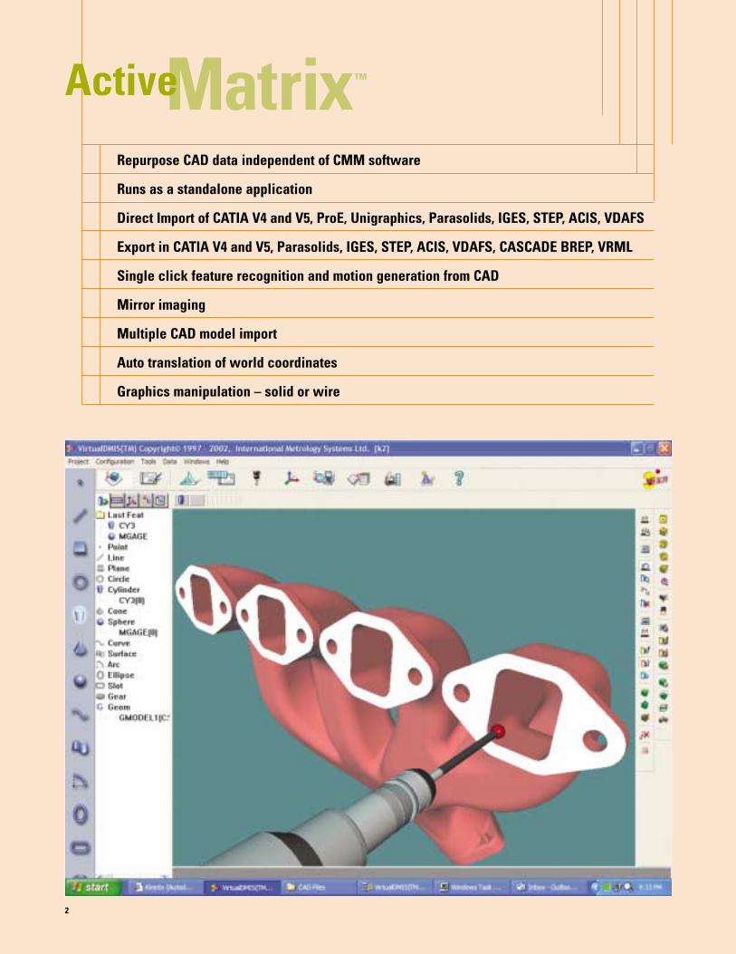
Repurpose CAD data independent of CMM software
Runs as a standalone application
Direct Import of CATIA V4 and V5, ProE, Unigraphics, Parasolids, IGES, STEP, ACIS, VDAFS
Export in CATIA V4 and V5, Parasolids, IGES, STEP, ACIS, VDAFS, CASCADE BREP, VRML
Single click feature recognition and motion generation from CAD
Mirror imaging
Multiple CAD model import
Auto translation of world coordinates
Graphics manipulation – solid or wire
2
Active

Virtual DMIS’ new Active Matrix™ CAD inter-
face creates a bi-directional link between
product design and measurement. Read and
write industry standard and native CAD data formats.
Active Matrix can be run as a stand-alone application
anywhere in the enterprise, providing product data
repurposing power wherever it is needed. Models
can be “cleaned up” prior to the start of programming
anywhere in the enterprise.
Virtual DMIS is built upon the next generation
CASCADE™ solid modeling engine and displays the
CAD model in a true solids format, providing the
ultimate in accuracy and enabling surface nominal
data and vectors to be selected directly from the
part model. Multiple models can be imported and
positioned on the Virtual CMM.
Full prismatic part geometry is available with
automatic feature recognition and measurement
simply by selecting the feature to be inspected with a
single mouse click.
Virtual DMIS has been developed with the Dimensional
Measurement Interface Standard (DMIS) as its
foundation and is engineered to fully exploit the
power and capabilities of this measuring technology
standard (ANSI/CAM-I 101-1995). Virtual DMIS lives
up to its name and utilizes DMIS in a pure native
format eliminating the need for translators and
provides a seamless two way exchange of DMIS
between CAD/CAM and CMM measuring systems.
3
Import all major CAD formats
Position the model on the Virtual machine
Single-click creation of nominal features
Use Active Matrix to clean up model before import
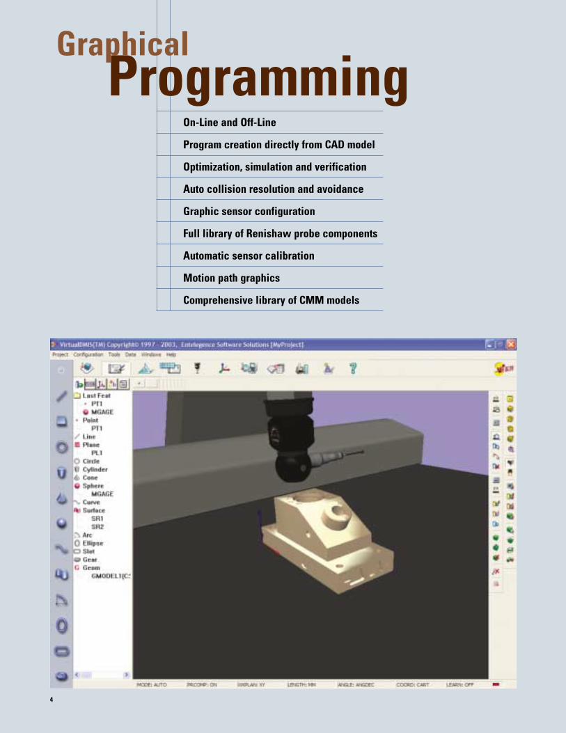
On-Line and Off-Line
Program creation directly from CAD model
Optimization, simulation and verification
Auto collision resolution and avoidance
Graphic sensor configuration
Full library of Renishaw probe components
Automatic sensor calibration
Motion path graphics
Comprehensive library of CMM models
4
Programming Graphical

Virtual DMIS runs as both an Off-Line or On-
Line application enabling CMM inspection
programs to be generated and verified at a
location that best serves the measurement task. On-
Line users can switch to Off-Line at the CMM,
enabling program editing and verification to occur
without risk of CMM structure crashes.
Graphical Programming allows inspection programs
to be generated in a virtual digital manufacturing
environment including full CMM and Probe kinematic
simulation and program verification and optimization
in advance of part inspection demand; reducing lead-
times and improving productive CMM utilization.
Probe Path Simulation enables effective program
prove out. CAD model manipulation tools allow the
model to be located in the optimum position within
the CMM volume regardless of design alignment.
Feature Based Measurement is achieved by
selecting the object to be measured. Auto feature
recognition, nominal feature definition and single
click‚ automatic entry to the nominal feature
database is seamlessly achieved.
A full 3D scaled dynamic representation of the CMM
and Renishaw Probing System from the extensive
on-line library provides real world simulation and
programming tools.
Solid Model based Collision Avoidance provide for
foolproof anti-crash assurance, protecting your
valuable equipment and maximizing uptime.
Off-line probe path simulation verifies motion
Solid model collision avoidance eliminates shaft probings
Full support for DMIS clearance surfaces
Program with or without a CAD model
5
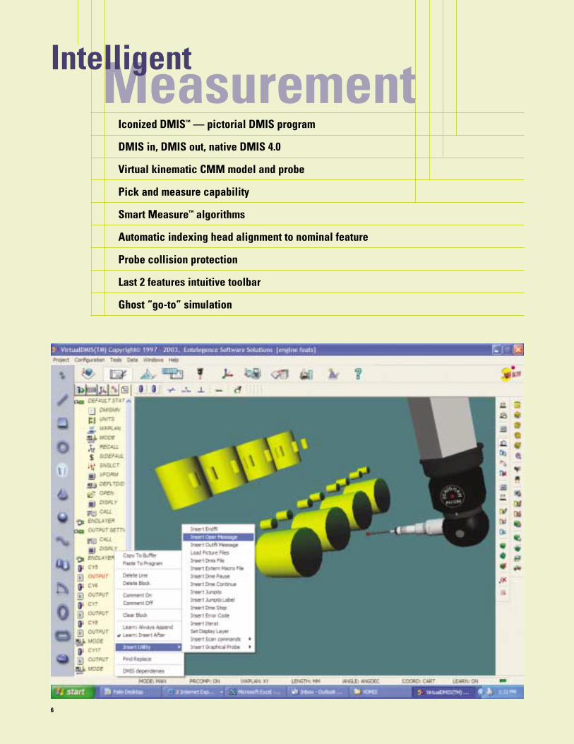
Iconized DMIS™ — pictorial DMIS program
DMIS in, DMIS out, native DMIS 4.0
Virtual kinematic CMM model and probe
Pick and measure capability
Smart Measure™ algorithms
Automatic indexing head alignment to nominal feature
Probe collision protection
Last 2 features intuitive toolbar
Ghost “go-to” simulation
6
Measurement Intelligent
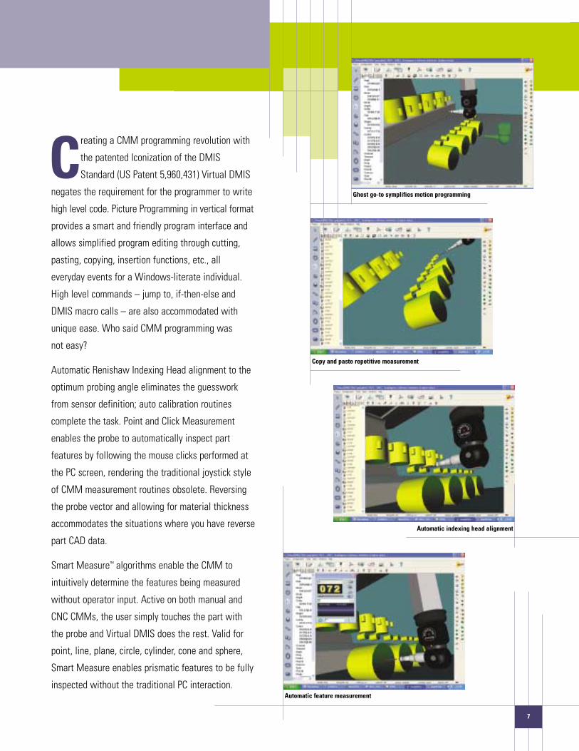
Creating a CMM programming revolution with
the patented Iconization of the DMIS
Standard (US Patent 5,960,431) Virtual DMIS
negates the requirement for the programmer to write
high level code. Picture Programming in vertical format
provides a smart and friendly program interface and
allows simplified program editing through cutting,
pasting, copying, insertion functions, etc., all
everyday events for a Windows-literate individual.
High level commands – jump to, if-then-else and
DMIS macro calls – are also accommodated with
unique ease. Who said CMM programming was
not easy?
Automatic Renishaw Indexing Head alignment to the
optimum probing angle eliminates the guesswork
from sensor definition; auto calibration routines
complete the task. Point and Click Measurement
enables the probe to automatically inspect part
features by following the mouse clicks performed at
the PC screen, rendering the traditional joystick style
of CMM measurement routines obsolete. Reversing
the probe vector and allowing for material thickness
accommodates the situations where you have reverse
part CAD data.
Smart Measure™ algorithms enable the CMM to
intuitively determine the features being measured
without operator input. Active on both manual and
CNC CMMs, the user simply touches the part with
the probe and Virtual DMIS does the rest. Valid for
point, line, plane, circle, cylinder, cone and sphere,
Smart Measure enables prismatic features to be fully
inspected without the traditional PC interaction.
Copy and paste repetitive measurement
Automatic indexing head alignment
Automatic feature measurement
Ghost go-to symplifies motion programming
7
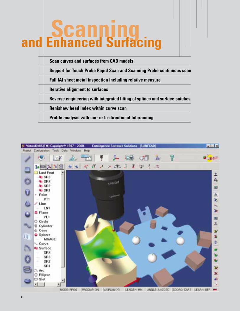
Scanning Scan curves and surfaces from CAD models
Support for Touch Probe Rapid Scan and Scanning Probe continuous scan
Full IAI sheet metal inspection including relative measure
Iterative alignment to surfaces
Reverse engineering with integrated fitting of splines and surface patches
Renishaw head index within curve scan
Profile analysis with uni- or bi-directional tolerancing
8
and Enhanced Surfacing

Combined with the 32 bit On-Motion controller
Virtual DMIS scans with touch probes at the
rate of 8 pts./sec. Rapid Scan™ provides a
10-fold increase over traditional point to point probing.
Continuous scanning with analog probes on CMMs
equipped with the Renishaw UCC1 provides data rates
up to hundreds of pts./sec. The Renishaw SP25, SP600
and SP80 are supported. Rapid Scan can be utilized for
reverse engineering or the comparison of actual scans to
their corresponding nominals.
Virtual DMIS revolutionizes CMM feature measurement
with Feature Scan.™ Developed as an enhancement of
Rapid Scan to scan features and provide a stream of points
rather than a few discrete points, allowing for more accu-
rate measurement. Feature scan is seamless and can be
applied automatically to features during CNC inspection.
The optional feature rich Enhanced Surfacing Module of
Virtual DMIS extends it capabilities as a supreme graphical
analysis tool for complex 3D surfaces at the CMM.
Iterative alignment routines allow the physical part to be
aligned accurately off the CAD model for the most
complex of parts. Click on the aligned CAD model and
the nominal definition and surface normal vectors are
automatically created. A single mouse click provides CNC
point measurement with deviations displayed graphically.
Automatic scanning and tolerancing of the nominal
surface provides a full visual report.
As a reverse engineering tool, Surfacing allows
automatic scanning of curves with data export in ASCII
or IGES Bspline Curve format. When scanning patches,
the actual surface is reconstructed at the CMM for
export as an IGES surface file.
A nominal grid of points can be automatically created
and overlayed on the CAD model to extract nominal data
points which can be measured under CNC execution at
the click of a mouse. 9
Profile results directly on CAD models
Profile results to printer
Cross sections from CAD model in multi view
Relative measure command set for thin-wall parts

Graphical display of measured results
Balloon display of nominal, actual and deviation
View manipulation during reporting
Pictorial reports appended with numerical data
Optional CAD model display
Whisker diagrams for rapid visual form analysis
SPC
10
GraphicalReporting
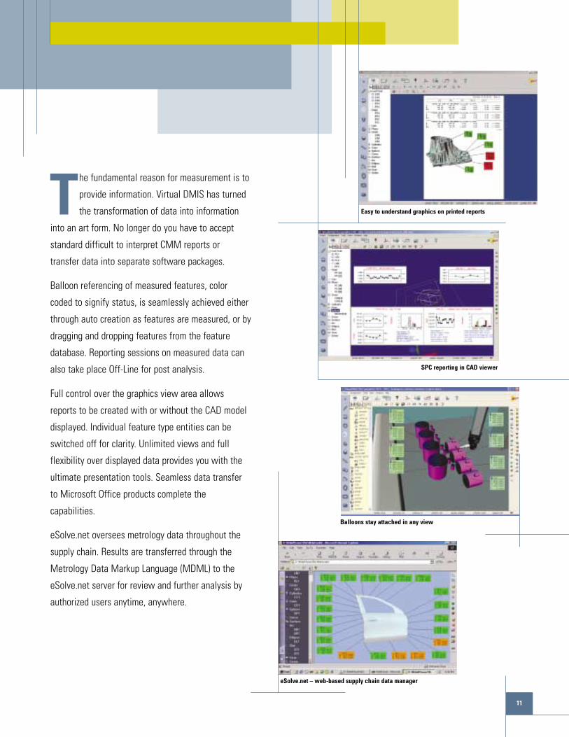
The fundamental reason for measurement is to
provide information. Virtual DMIS has turned
the transformation of data into information
into an art form. No longer do you have to accept
standard difficult to interpret CMM reports or
transfer data into separate software packages.
Balloon referencing of measured features, color
coded to signify status, is seamlessly achieved either
through auto creation as features are measured, or by
dragging and dropping features from the feature
database. Reporting sessions on measured data can
also take place Off-Line for post analysis.
Full control over the graphics view area allows
reports to be created with or without the CAD model
displayed. Individual feature type entities can be
switched off for clarity. Unlimited views and full
flexibility over displayed data provides you with the
ultimate presentation tools. Seamless data transfer
to Microsoft Office products complete the
capabilities.
eSolve.net oversees metrology data throughout the
supply chain. Results are transferred through the
Metrology Data Markup Language (MDML) to the
eSolve.net server for review and further analysis by
authorized users anytime, anywhere.
11
Easy to understand graphics on printed reports
SPC reporting in CAD viewer
Balloons stay attached in any view
eSolve.net – web-based supply chain data manager

Virtual DMIS has been designed to support an open-ended array of add-on modules.
Customize Virtual DMIS to deliver the complete application solution for your enterprise
by adding one or more of these optional modules:
Virtual Vision+™ Multi-Sensor Software
Virtual Gear
Virtual Excel
Virtual SPC
12
AdditionalModules

Virtual Vision+ brings CAD and multi-sensor
functionality together in one environment.
Virtual Vision+ allows optical measurement
on a standard CMM or on a dedicated video CMM
system. Intuitive lighting control and support for
single or dual monitor PC configurations maximizes
programming efficiency.
With Virtual Gear, Helical and Spur gear measurement
can be performed with or without a Rotary table. Gear
Inspection routines and reports are automatically
created after defining gear data according to the
appropriate standard. AGMA, DIN and ISO standards
are supported.
The Virtual Excel module links the output window
directly to an Excel spreadsheet. Values can be
automatically inserted into spreadsheet cells for post
measurement processing with formulas and Visual
Basic macros. Virtual DMIS commands for importing
values from spreadsheets into the Virtual DMIS
environment are also included.
Virtual SPC adds SPC functionality to the Virtual
DMIS environment. X-bar and R charts, Histograms,
Run charts and Capability studies including derivation
of Cp and Cpk are supported. Export of data into
Excel is supported for SPC data. Balloons with SPC
reports can be overlaid on CAD model images for
easy understanding of the process.
13
Virtual Gear for helical and spur gears
Virtual Excel merges the Virtual DMIS and Excel environments
Virtual SPC places SPC reports on CAD model
Virtual Vision+ CAD -based multi-sensor environment
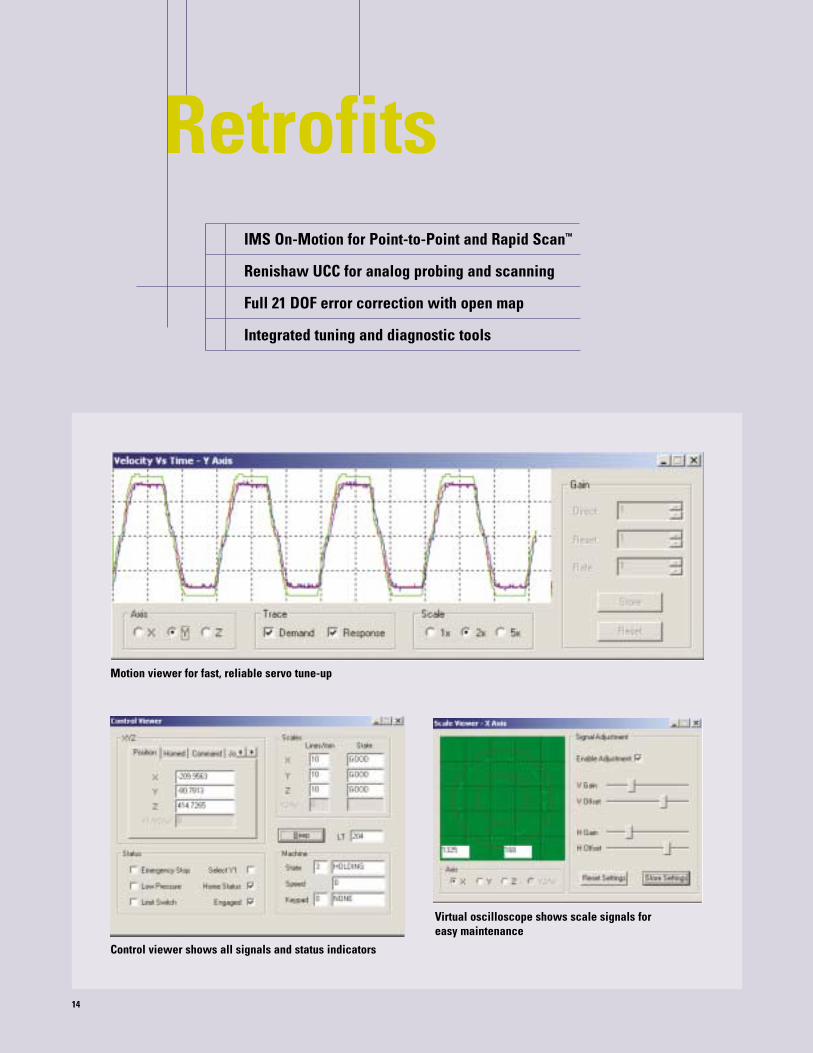
IMS On-Motion for Point-to-Point and Rapid Scan™
Renishaw UCC for analog probing and scanning
Full 21 DOF error correction with open map
Integrated tuning and diagnostic tools
14
Retrofits
Control viewer shows all signals and status indicators
Virtual oscilloscope shows scale signals for easy maintenance
Motion viewer for fast, reliable servo tune-up
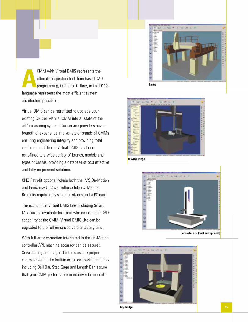
ACMM with Virtual DMIS represents the
ultimate inspection tool. Icon based CAD
programming, Online or Offline, in the DMIS
language represents the most efficient system
architecture possible.
Virtual DMIS can be retrofitted to upgrade your
existing CNC or Manual CMM into a “state of the
art” measuring system. Our service providers have a
breadth of experience in a variety of brands of CMMs
ensuring engineering integrity and providing total
customer confidence. Virtual DMIS has been
retrofitted to a wide variety of brands, models and
types of CMMs, providing a database of cost effective
and fully engineered solutions.
CNC Retrofit options include both the IMS On-Motion
and Renishaw UCC controller solutions. Manual
Retrofits require only scale interfaces and a PC card.
The economical Virtual DMIS Lite, including Smart
Measure, is available for users who do not need CAD
capability at the CMM. Virtual DMIS Lite can be
upgraded to the full enhanced version at any time.
With full error correction integrated in the On-Motion
controller API, machine accuracy can be assured.
Servo tuning and diagnostic tools assure proper
controller setup. The built-in accuracy checking routines
including Ball Bar, Step Gage and Length Bar, assure
that your CMM performance need never be in doubt.
15
Gantry
Moving bridge
Horizontal arm (dual arm optional)
Ring bridge