improving the performance of distance relays in the
TRANSCRIPT

U.P.B. Sci. Bull., Series C, Vol. 83, Iss. 1, 2021 ISSN 2286-3540
IMPROVING THE PERFORMANCE OF DISTANCE RELAYS
IN THE PROTECTION OF SHORT TRANSMISSION LINES
BASED ON THE CURRENT ESTIMATION OF THE LINE
END
Seyed Mohammad Sadegh HOSSEINIMOGHADAM1, Masoud DASHTDAR
2,
Majid DASHTDAR3
This paper proposes a method to improve the performance of distance relays in short transmission lines. The most important problems of distance relays in short
lines protection are the effect of fault resistance and the problem of small voltage at
the relay location and as a result, increase the error of voltage transformers (CVT).
Eliminates the mentioned drawbacks by using the current magnitude at the end of
the line which improves the performance of the distance relay. The performance of
the proposed method has been evaluated and analyzed using simulation in ATP-
EMTP software and has been compared with the existing methods.
Keywords: Distance Protection, Short Transmission Line, Digital Relays, Fault
Resistance
1. Introduction
The transmission line is one of the most important equipment of the power
system, the protections which is very important from maintaining the stability of
the system aspects and preventing the damage of the equipment due to the short
circuit current. Moreover, the large distance between the terminals at the
beginning and end of the line, transmission line protection is one of the most
complex types of protection in the power system. Transmission line protection has
applied in different ways. The most common line protection method is for
medium and long lines is distance protection [1]. This protection method performs
the protection operation by calculating the impedance seen from the relay location
to the fault location and comparing it with the pre-defined protection areas. In
addition to the distance method, several other methods have been proposed in
different references. Even though the introduction of alternative methods for
1 Electrical Engineering Department, Bushehr branch, Islamic Azad University, Bushehr, Iran,
e-mail: [email protected] 2 Electrical Engineering Department, Bushehr branch, Islamic Azad University, Bushehr, Iran,
e-mail: [email protected] 3 Electrical Engineering Department, Bushehr branch, Islamic Azad University, Bushehr, Iran,
e-mail: [email protected]

216 Seyed Mohammad Sadegh Hosseinimoghadam, Masoud Dashtdar, Majid Dashtdar
distance protection, and this protection method is still the most common method
of line protection. One of the main problems of the distance relay is the effect of
fault resistance. Typically, the effect of resistance on phase-to-phase faults is less
because the only spark resistance is between the two-phases. But when short-
circuit occurs with ground resistance at the ends of the protection zone, the
impedance measured by the relay will be overreached from its protection zone and
the relay will not operate (According to Fig. 1). The effect of fault feeding from
different sources will also exacerbate the adverse effect of fault resistance [2-4].
Fig. 1. The effect of fault resistance on the performance of the distance relay
In the case of short lines, the use of distance protection, in addition to the
above-mentioned problems, also faces other problems. Due to the small
impedance of short lines, Source to Line Impedance Ratio (SIR) is a large
number. In general, in protection, a short zone refers to a line whose SIR is large.
So a 30 km line with a low SIR will look like a long line. But a 100 km line with a
high SIR behaves like a short zone. Lines with a SIR larger than 4 km are usually
considered short zones of protection [2]. According to the definition provided for
the short zone, if an internal short-circuit occurs, the voltage seen at the relay
location will be much smaller than the nominal voltage of the system. Because
this voltage is obtained by dividing the voltage between the line and the
equivalent source of the network. This causes the smallest voltage measurement
error to interfere with relay performance. Because the voltage of transformers has
high performance around the nominal values, if the voltage at the relay location is
much lower than the nominal voltage of the system, the error of the voltage
transformers will be significant. When the SIR ratio increases according to

Improving the performance of distance relays in the protection of short transmission lines (…) 217
Equation (1), the voltage at the relay location (VR in Fig. 2) drops intensity. This
high voltage drop causes the capacitor transformers to malfunction.
(1)
Fig. 2. Fault at point F inside the short transmission line
Even if voltage transformers are ignored, the distance relays will not
perform reliably for small voltages. Also, the short lines distance relays are
exposed to transient vision increase due to the transient states of capacitive
voltage transformers [2]. Due to the above problems, the use of current methods
in the protection of short zones has become common. Current methods have been
implemented in a variety of ways, including comparing the current phase and
using the current difference [4-8]. These methods generally require a complex and
fast communication channel to exchange information between two posts.
Therefore, the use of these methods, in addition to the high cost of
implementation, has the problem that any error in the communication channel will
cause improper or incorrect operation of the relay. However, one of the
advantages of current methods is that there is no need for voltage information.
Therefore, the relay which uses the mentioned method is simpler and at the same
time, the need for voltage transformer is eliminated. However, voltage
transformers are still needed for purposes such as measuring and synchronizing.
In contrast, this method is highly dependent on the communication channel, and
any error in the channel will cause the relay to malfunction. Therefore, the
telecommunication equipment used needs support equipment, and as a result, the
cost of the project increases. Reference [9] presents a different method for short
transmission line protection. This method uses a high-frequency signal sent from
the relay to the line and uses a phase comparator to differentiate between lagging
and leading currents when a ground fault occurs. The advantage of this method is
its high-performance speed. The use of high-frequency signals, if there is a noise,
effects of this method performance. Another method that can be used to line
protection is neural networks. These networks have been studied in several papers
to implement the transmission line protection [11-18]. In some of these methods,
the neural network determines the fault location based on the voltage and current

218 Seyed Mohammad Sadegh Hosseinimoghadam, Masoud Dashtdar, Majid Dashtdar
information on both sides of the line. Naturally, this method requires a fast and
secure telecommunication channel to transmit three-phase voltage and current
information to the opposite post. In reference [13] only the fault direct is sent
through the channel and the relay uses it and local information about the fault is
decided. In reference [21], considering that the voltage and current of the fault
location are the same phase and using the voltage and current information, the
fault location is determined.
In this paper, in the second part, a method for calculating the voltage at the
relay location of the short transmission line is proposed. Then, considering that
the voltage drop on the short transmission line is negligible, the fault current at the
end of the transmission line is estimated. Finally, the fault location is determined
using the current values as well as the estimated voltage. In the third part, the
simulation has done, and the analysis of its results has presented. Finally, in the
fourth section, the conclusion has presented.
2. The proposed method for protection of short transmission lines
According to Fig. 3, when a fault occurs in a short transmission line, fault
currents are generated from both ends of the transmission line to the fault location.
In Fig. 3, ZL is the impedance of the entire transmission line and x percent of the
line length at which the fault occurred. In this section, the proposed method for
short transmission lines protection against various faults has presented. The
purpose of this method is to overcome the problems caused by the low voltage of
the relay location and the effect of fault resistance.
Fig. 3. The fault with Rf resistance inside the short transmission line
2.1.Single-phase fault to ground
If the single-phase fault to ground a-g occurs according to Fig. 4 at
distance x from terminal A, Equation (2) can be used to estimate the fault location
and the fault resistance value [21].
(2)

Improving the performance of distance relays in the protection of short transmission lines (…) 219
In Equation (2), indices i and r represent the imaginary part and the real
part of the corresponding parameter, respectively. VAm represents the phase m
voltage at the beginning of the transmission line in volts and x indicates the
distance of the fault location from the beginning of the transmission line in meters
and IFm represents the fault current, which is the sum of the fault current at the
beginning of the transmission line (IAm) and the end of the transmission line (IBm)
in amperes. Also:
Fig. 4. Single-phase-ground fault at distance x from terminal A
(3)
(4)
Wherein:
k: a, b, c phases
Zmk: Mutual impedance between phase m and phase k in ohm per meter.
IAk: Phase k current at the beginning of the transmission line in amperes.
IBk: Phase k current at the end of the transmission line in amperes.
In Equation (2), the only parameter that is not directly available to the
relay at the beginning of the transmission line is the end current of the
transmission line that is being passed to the fault point (IBa current in Fig. 4). In
the following, a method for estimating the current at the end of the transmission
line is proposed and then the fault location and fault resistance are calculated
using Equation (2).
The steps for performing the proposed method for single-phase-ground
fault are as follows:
1) It is assumed that the Thevenin equivalent impedance of the sources on
both sides of the short transmission line, ie ZS1 and ZS2 in Fig. 3, is
provided in the relay. Thevenin impedance refers to the impedance of
network equivalent symmetric components.

220 Seyed Mohammad Sadegh Hosseinimoghadam, Masoud Dashtdar, Majid Dashtdar
2) Under normal conditions, the Thevenin source voltage (positive
component source voltage) is calculated from the beginning of the
transmission line, ie V1< δ1 in Fig. 3, using VA voltage values and IA
current, as well as the source impedance ZS1.
3) Given the current and voltage in normal conditions, the VB voltage and
IB current at the end of the transmission line are calculated by the line
transfer matrix, according to Equation (5).
(5)
4) The Thevenin equivalent source voltage (positive component source
voltage) at the end of the transmission line, ie V2 < δ2 in Fig. 3, is
calculated similarly to step 2.
5) It is assumed that when a single-phase-ground fault occurs (a-g), the
voltage at the fault location is equal to the voltage at the beginning of
the transmission line and that is equal to the voltage at the end of the
transmission line. That is, the voltages VAa, VBa, and Vfa in Fig. 4 are
equal.
(6)
This assumption is made by considering that the impedance of the
transmission line is small and the voltage drop across is negligible. As
a result, the symmetrical components of the voltage are equal.
(7)
6) The equivalent circuit of the symmetrical components of the network
when a single-phase (a-g) fault occurs, in the form of Fig. 5.
Considering the Equation (7) and that the voltage drop across the
transmission line is negligible, the symmetric components of the
voltage are calculated as Equations (8) to (11).
(8)
(9)
(10)
Phase-a voltage is calculated using Equation (6) to (11).
7) According to Fig. 4, to calculate the current IB+, the voltage drop
across the transmission line is eliminated. Therefore, the positive
component of the end current of the transmission line is calculated
using Equation (11).
(11)
8) As shown in Fig. 5, the components of the fault current are equal to
each other. The fault current is in the form of an Equation (12).
(12)

Improving the performance of distance relays in the protection of short transmission lines (…) 221
Therefore, the negative and zero components of the end current of the
line are calculated using Equations (11) and (12).
(13)
(14)
As a result, the end current of the transmission line is calculated using
Equation (11) to (14).
9) Finally, all the necessary parameters for estimating the fault location
by Equation (2) are available to the relay. Therefore, the relay will
calculate the fault location and the value of fault resistance.
10)
Fig. 5. The equivalent circuit of the symmetrical components of the network in single-
phase-ground fault mode
Fig. 6. Two-phase fault at a distance x from terminal A

222 Seyed Mohammad Sadegh Hosseinimoghadam, Masoud Dashtdar, Majid Dashtdar
2.2. Two-phase fault
If the two-phase fault b-c occurs according to Fig. 6 at distance x from
terminal A, Equation (15) could be used to estimate the fault location and the fault
resistance value [21].
(15)
In Equations (15), M3 and M4 are defined as Equations (16) and (17). In
Equations (15) to (17), m and n are the phases involved in the fault.
(16)
(17)
Wherein:
k: a, b, c phases
Zmk: Mutual impedance between phase m and phase k in ohm per meter.
Znk: Mutual impedance between phase n and phase k in ohm per meter.
IAk: Phase k current at the beginning of the transmission line in amperes.
IBk: Phase k current at the end of the transmission line in amperes.
Fig. 7. The equivalent circuit of the symmetrical components of the network in two-phase fault
mode
The steps for performing the proposed method for the fault of two-phase
together are as follows:
Stages 1 to 6 for this type of fault are similar to steps 1 to 6 in Sections 2-
1, except that in this section the fault is b-c and therefore instead of Equation (10)
from Equation (18) should be used.

Improving the performance of distance relays in the protection of short transmission lines (…) 223
(18)
Similar to single-phase-ground faults, phase b and c voltages are
calculated using Equations (8), (9), and (18). The equivalent circuit of the
symmetrical components of the network when a two-phase (b-c) fault occurs in
the form of Fig. 7.
The continuation of the algorithm from step 7 is as follows:
7) According to Fig. 7, to calculate the components of the current at the
end of the line, the voltage drop across the transmission line is
eliminated. Therefore, the symmetrical components of the current of
the transmission line end are calculated using Equation (19) to (21).
(19)
(20)
(21)
Therefore, the current at the end of the transmission line is calculated
using the Equation (19) to (21).
8) Finally, all the necessary parameters for estimating the fault location
by Equation (15) are available to the relay. Therefore, the relay could
calculate the fault location.
9)
Fig. 8. Three-phase-ground fault at distance x from terminal A
2.3.Three-phase fault
If the three-phase fault a-b-c occurs according to Fig. 8 at distance x from
terminal A, Equation (22) could be used to estimate the fault location and the fault
resistance value [21].

224 Seyed Mohammad Sadegh Hosseinimoghadam, Masoud Dashtdar, Majid Dashtdar
(22)
In Equation (22), the parameters M1 and M2 of each phase are calculated
using Equations (3) and (4). Also:
(23)
(24)
The proposed method steps for a three-phase fault to the ground are as
follows:
Stages 1 to 6 for this type of fault are similar to steps 1 to 6 in Sections 2-
1, except that in this section the fault is a-b-c-g and therefore instead of Equation
(9) and (10) from Equation (25) and (26) should be used.
(25)
(26)
The symmetrical components of the voltage and therefore the voltage of
phases a, b and c are calculated using Equations (8), (25), and (26). The
equivalent circuit of the symmetrical components of the network when a three-
phase fault (a-b-c-g) occurs in the form of Fig. 9.
Fig. 9. The equivalent circuit of the symmetrical components of the network in three-phase-
ground fault mode
The continuation of the algorithm from step 7 is as follows:
7) According to Fig. 9, to calculate the current IB+, the voltage drop
across the transmission line is eliminated. Therefore, the positive
component of the current of the transmission line end is calculated
using Equation (27).
(27)

Improving the performance of distance relays in the protection of short transmission lines (…) 225
8) Due to the symmetry, the negative and zero components of the current
will not exist and are considered equal to zero. Therefore, the phase
currents at the end of the transmission line are calculated and the fault
location is calculated through Equation (22).
As explained in the proposed method, first the type of short-circuit must
be known, then the protection algorithm will perform the appropriate performance
based on the type of short-circuiting. It is important to note that the short-circuit
type detection in relays, especially new relays, could be easily detected by fault
detector units. These units usually easily identify the type of short-circuit by
comparing the present current sample with the previous cycle current sample [22].
3. System modeling and simulation results
Fig. 10 shows the network used to simulate the proposed protection
methods. The simulation has done in ATP-EMTP software and the network
equivalent sources specifications are as follows.
Fig. 10. The equivalent circuit of the symmetrical components of the network in three-phase-
ground fault mode
S1: 230 kV, 50Hz, ZS1+ = 0.64+ j8.32Ω, ZS10 = 3.2+ j13.44Ω, δ1= 10˚
S2: 230 kV, 50Hz, ZS2+ = 1.28+ j33.12Ω, ZS20 = 0.96+ j27.84Ω, δ1= 20˚
Fig. 11. Impedance observed single-phase fault to the ground at a distance of 5 km from the
beginning of the transmission line and with a resistance of 20 ohm

226 Seyed Mohammad Sadegh Hosseinimoghadam, Masoud Dashtdar, Majid Dashtdar
Fig. 12. Impedance observed single-phase fault to the ground at a distance of 5 km from the
beginning of the transmission line and with a resistance of 5 ohm
The long transmission line is 200 km, and the short transmission line is 20
km, and the impedance of the positive component is 0.0162+ j0.2793 Ω/km and
the impedance of the zero component is 0.1588+ j0.6458 Ω/km. The self-
impedances are 0.063686+ j0.401414 Ω/km and the mutual impedance between
phases is 0.047526+ j0.122181 Ω/km. Also, the rapid protection zone of the
distance relay is set to 80% of the transmission line.
All voltage and current signals are saved as a matrix via ATP-EMTP
software. These matrices are then called in the MATLAB software and the
necessary calculations are performed on these signals. The method used to
estimate the phasor is the return Fourier algorithm method [23-24]. If a single-
phase-ground fault occurs 5 km from the beginning of the short transmission line
with a resistance of 20 ohms, the relay performance is shown in Fig. 11. If a
single-phase-ground fault occurs 5 km from the beginning of the short
transmission line with a resistance of 5 ohms, the relay performance is shown in
Fig. 12.
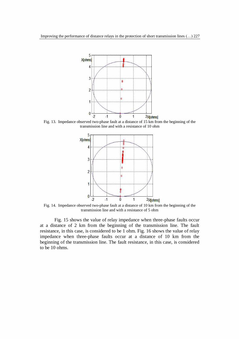
Fig. 13 shows the value of relay impedance when two-phase faults occur
at a distance of 15 km from the beginning of the transmission line. The fault
resistance, in this case, is considered to be 10 ohms. Fig. 14 shows the value of
relay impedance when two-phase faults occur at a distance of 10 km from the
beginning of the transmission line. The fault resistance, in this case, is considered
to be 5 ohms.
Improving the performance of distance relays in the protection of short transmission lines (…) 227
Fig. 13. Impedance observed two-phase fault at a distance of 15 km from the beginning of the
transmission line and with a resistance of 10 ohm
Fig. 14. Impedance observed two-phase fault at a distance of 10 km from the beginning of the
transmission line and with a resistance of 5 ohm
Fig. 15 shows the value of relay impedance when three-phase faults occur
at a distance of 2 km from the beginning of the transmission line. The fault
resistance, in this case, is considered to be 1 ohm. Fig. 16 shows the value of relay
impedance when three-phase faults occur at a distance of 10 km from the
beginning of the transmission line. The fault resistance, in this case, is considered
to be 10 ohms.

228 Seyed Mohammad Sadegh Hosseinimoghadam, Masoud Dashtdar, Majid Dashtdar
Fig. 15. Impedance observed three-phase fault to the ground at a distance of 2 km from the
beginning of the transmission line and with a resistance of 1 ohm
Fig. 16. Impedance observed three-phase fault to the ground at a distance of 10 km from the
beginning of the transmission line and with a resistance of 20 ohm
Table 1
Percentage of impedance measurement error in the case of a fault a-g
Fault
location
(km)
Fault
resistance
(ohm)
Common
distance
Method
[20]
The proposed
method
5
1 98 22 54
5 865 80 53
10 1742 154 50
20 3613 150 42
10
1 36 30 27
5 473 46 23
15 1425 128 20
20 1936 178 18
15 1 20 13 16

Improving the performance of distance relays in the protection of short transmission lines (…) 229
5 300 34 15
10 674 60 14
20 1300 120 9
The following is a comparison between the proposed method with the
common distance method and also the method presented in reference [20] in
Tables 1 to 3. In the method presented in reference [20,] considering that the
impedance of the fault path is often ohmic property when the fault occurs, and as
a result the voltage angle and current of the fault location are equal, the fault
location is estimated. Tables 1 to 3 compare single-phase to ground faults, two-
phase and three-phase faults, respectively. Also, as shown in Fig. 2, the voltage at
the relay location in short transmission lines drops sharply when a fault occurs.
Therefore, voltage measuring transformers under these conditions will face error
measures. In comparison, the voltage measurement transformer error is
considered to be 6% in amplitude and 4-degree phase difference. The magnitude
of this error is based on the reference [25] for voltage transformers. Table 2
Percentage of impedance measurement error in the case of a fault b-c
Fault
location (km)
Fault
resistance (ohm)
Common distance
Method [20]
The proposed method
5
1 114 32 6
5 900 166 24
10 1900 260 34
10
1 41 20 7
5 500 80 11
15 1020 130 16
15
1 20 11 7
5 366 53 7
10 717 86 10
Table 3
Percentage of impedance measurement error in the case of a fault a-b-c-g
Fault
location
(km)
Fault
resistance
(ohm)
Common
distance
Method
[20]
The proposed
method
5
1 7 6 6
5 7 6 6
10 7 6 5
10
1 7 5 5
5 10 5 4
15 10 7 3
15
1 8 6 5
5 10 6 4
10 10 6 4

230 Seyed Mohammad Sadegh Hosseinimoghadam, Masoud Dashtdar, Majid Dashtdar
4. Analysis of simulation results
Based on the simulations presented in Section 3, the following results are
obtained:
The proposed method does not require a voltage signal during the
short-circuit. Because one of the main problems with short
transmission lines protection is the error of voltage measuring
transformers at low voltages, the lack of need for voltage signal during
the fault significantly improves the performance of the proposed
method compared to previous methods.
As could be seen from the results obtained in Tables 1 to 3, except in
cases where the fault resistance is considered to be very low, in other
cases the proposed method has less error than other methods.
However, it should be noted that usually, the minimum fault resistance
is due to the presence of a spark, the value which is about 5 ohms.
Therefore, the proposed method is more practical in comparison with
the previous two methods.
The proposed method does not require a communication channel to
communicate between the stations at the beginning and end of the
transmission line. The voltage and current at the end of the
transmission line are estimated using the values of voltage and current
at the beginning of the transmission line. As a result, error problems
due to errors in sending information or errors in the telecommunication
channel that exist in the common methods will not be present in the
proposed method.
As the fault resistance increases, the accuracy of the proposed method
increases compared to other methods. Because in this case, the voltage drop
across the short transmission line impedance is less. As a result, the voltage at the
beginning of the transmission line, which is assumed to be equal to the voltage at
the end, has a lower error. Therefore, increasing fault resistance improves the
performance of the proposed method.
5. Conclusion
In this paper, a method for improving the performance of the distance
relay in the protection of short transmission lines was proposed. This method uses
voltage data before the fault occurs as well as the current during short-circuit,
estimates the voltage and current at the end of the transmission line, and then use
this information to estimate the fault location. The approximations used in this
method and the lack of need for voltage during short-circuit increase the
efficiency of the proposed method compared to similar methods. The proposed

Improving the performance of distance relays in the protection of short transmission lines (…) 231
method for fault resistance of up to 20 ohms has had a more appropriate response
than other similar methods in improving the performance of short transmission
lines distance relays.
R E F E R E N C E S
[1]. Eissa, M. M., and M. Masoud. "A novel digital distance relaying technique for transmission
line protection." IEEE Transactions on Power Delivery 16, no. 3 (2001): 380-384.
[2]. Elmore, Walter A. Protective relaying: theory and applications. Vol. 1. CRC Press, 2003.
[3]. Horowitz, Stanley H., and Arun G. Phadke. Power system relaying. Vol. 22. John Wiley &
Sons, 2008.
[4]. Sun, Shan C. "Phase comparison relaying system with the single-channel communications
link." U.S. Patent 4,935,837, issued June 19, 1990.
[5]. Warrington, AR van C. "Protective relaying (or long transmission lines." Electrical Engineering 62, no. 6 (1943): 261-268.
[6]. Dambhare, Sanjay, S. A. Soman, and M. C. Chandorkar. "Adaptive current differential
protection schemes for transmission-line protection." IEEE Transactions on Power
Delivery 24, no. 4 (2009): 1832-1841.
[7]. Rosolowski, Eugeniusz, Jan Izykowski, and Murari M. Saha. "Fault location algorithm for use
with current differential protective relays of double-circuit line." In 2009 IEEE Bucharest
PowerTech, pp. 1-6. IEEE, 2009.
[8]. Dashtdar, Masoud, and Majid Dashtdar. "Fault Location in Distribution Network Based on
Fault Current Profile and The Artificial Neural Network." Mapta Journal of Electrical and
Computer Engineering (MJECE) 2, no. 1 (2020): 30-41.
[9]. El-Alaily, A. A., and M. M. Mandour. "A comprehensive form for the protection of very short
transmission lines." Electric power systems research 14, no. 3 (1988): 227-232. [10]. Sadinezhad, I., and M. Joorabian. "A new adaptive hybrid neural network and fuzzy logic-
based fault classification approach for transmission lines protection." In 2008 IEEE 2nd
International Power and Energy Conference, pp. 895-900. IEEE, 2008.
[11]. Aggarwal, R. K., J. Iglesias Lorenzo, and A. L. Orille. "Implementation and laboratory test of
a fully integrated neural network-based protection relay for high voltage transmission
lines." (2004): 72-75.
[12]. Dashtdar, M., M. Esmaeilbeig, M. Najafi, and M. Esa Nezhad Bushehri. "Fault Location in
the Transmission Network Using Artificial Neural Network." Automatic Control and
Computer Sciences 54, no. 1 (2020): 39-51.
[13]. Dashtdar, Masoud, Mostafa Esmailbeag, and Mojtaba Najafi. "Fault Location in the
Transmission Network based on Zero-sequence Current Analysis using Discrete Wavelet Transform and Artificial Neural Network." Computational intelligence in electrical
engineering 10, no. 4 (2019): 87-102.
[14]. Dashtdar, Majid, and Masoud Dashtdar. "Fault Location in the Transmission Network Using
a Discrete Wavelet Transform." American Journal of Electrical and Computer
Engineering 3, no. 1 (2019): 30-37.
[15]. Dashtdar, Majid, and Masoud Dashtdar. "Fault location in the transmission network based on
extraction of fault components using wavelet transform." The Scientific Bulletin of
Electrical Engineering Faculty 19, no. 2 (2019): 1-9.
[16]. Oonsivilai, Anant, and Sanom Saichoomdee. "Appliance of the recurrent neural network
toward distance transmission lines protection." In TENCON 2009-2009 IEEE Region 10
Conference, pp. 1-4. IEEE, 2009.

232 Seyed Mohammad Sadegh Hosseinimoghadam, Masoud Dashtdar, Majid Dashtdar
[17]. Lahiri, Uttama, A. K. Pradhan, and S. Mukhopadhyaya. "Modular neural network-based
directional relay for transmission line protection." IEEE Transactions on Power Systems 20,
no. 4 (2005): 2154-2155.
[18]. Wu, Q. H., J. F. Zhang, and D. J. Zhang. "Ultra-high-speed directional protection of
transmission lines using mathematical morphology." IEEE transactions on power
delivery 18, no. 4 (2003): 1127-1133.
[19]. Dashtdar, Masoud, Rahman Dashti, and Hamid Reza Shaker. "Distribution network fault
section identification and fault location using artificial neural network." In 2018 5th
International Conference on Electrical and Electronic Engineering (ICEEE), pp. 273-278. IEEE, 2018.
[20]. Xu, Zhen Yu, G. Xu, Li Ran, S. Yu, and Q. X. Yang. "A new fault-impedance algorithm for
distance relaying on a transmission line." IEEE transactions on power delivery 25, no. 3
(2010): 1384-1392.
[21]. Salim, Rodrigo Hartstein, Mariana Resener, André Darós Filomena, Karen Rezende Caino
De Oliveira, and Arturo Suman Bretas. "Extended fault-location formulation for power
distribution systems." IEEE transactions on power delivery 24, no. 2 (2009): 508-516.
[22]. Ziegler, Gerhard. Numerical distance protection: principles and applications. John Wiley &
Sons, 2011.
[23]. Darwish, Hatem A., and Magdy Fikri. "Practical considerations for recursive DFT
implementation in numerical relays." IEEE Transactions on Power Delivery 22, no. 1 (2006): 42-49.
[24]. Phadke, Arun G., and James S. Thorp. Computer relaying for power systems. John Wiley &
Sons, 2009.
[25]. ALSTOM (Firm). Network protection & automation guide. Alstom, 2002.