improving processor efficiency through enhanced instruction fetchwhalley/papers/hines_diss08.pdf ·...
TRANSCRIPT
FLORIDA STATE UNIVERSITY
COLLEGE OF ARTS AND SCIENCES
IMPROVING PROCESSOR EFFICIENCY THROUGH ENHANCED
INSTRUCTION FETCH
By
STEPHEN R. HINES
A Dissertation submitted to theDepartment of Computer Science
in partial fulfillment of therequirements for the degree of
Doctor of Philosophy
Degree Awarded:Summer Semester, 2008

The members of the Committee approve the Dissertation of Stephen R. Hines defended
on June 27, 2008.
David WhalleyProfessor Co-Directing Dissertation
Gary TysonProfessor Co-Directing Dissertation
Gordon ErlebacherOutside Committee Member
Robert van EngelenCommittee Member
Piyush KumarCommittee Member
Andy WangCommittee Member
The Office of Graduate Studies has verified and approved the above named committee members.
ii

To Katy, Mom, Dad, Frank, and the restof my family and friends who have always
believed that I could do this . . .
iii

ACKNOWLEDGEMENTS
I would most like to thank my advisors Gary Tyson and David Whalley for their insightful
discussions, support, and guidance throughout the Ph.D. process. Your kind words of
encouragement let me know that you understood all too well the pressures of being a graduate
student. You have certainly inspired my research career through all the great projects we
have worked on together.
I would also like to thank the other students that I have worked alongside for these past
several years. Whether we were having a heated discussion about multicore, talking about
Futurama, or playing a quick game of Magic, each of you certainly helped me to not only
survive but thrive in this setting. Being a research assistant in our lab is probably more fun
than it should be. I would especially like to thank Prasad Kulkarni for being a great friend
and co-worker.
It goes without saying that I am grateful for all of the love and support that my wife
has given me. I would be pretty lost without you, and I am sure that I would have found a
reason to leave this unfinished. I would also really like to thank the rest of my family and
friends. Mom, Dad, Frank, Erin, Meena, Nanda, Mugunth, . . . ; you have always been there
for me when I needed you most. I feel truly blessed to have each of you in my life.
iv

TABLE OF CONTENTS
List of Tables . . . . . . . . . . . . . . . . . . . . . . . . . . . . . . . . . . . . . . vii
List of Figures . . . . . . . . . . . . . . . . . . . . . . . . . . . . . . . . . . . . . viii
Abstract . . . . . . . . . . . . . . . . . . . . . . . . . . . . . . . . . . . . . . . . xi
1. Introduction . . . . . . . . . . . . . . . . . . . . . . . . . . . . . . . . . . . . 11.1 Instruction Fetch . . . . . . . . . . . . . . . . . . . . . . . . . . . . . . . 11.2 Instruction Register File . . . . . . . . . . . . . . . . . . . . . . . . . . . 11.3 Exploiting Guarantees of Fetch Behavior . . . . . . . . . . . . . . . . . . 31.4 Contributions and Impact . . . . . . . . . . . . . . . . . . . . . . . . . . 31.5 Dissertation Outline . . . . . . . . . . . . . . . . . . . . . . . . . . . . . 5
2. Instruction Packing with an IRF . . . . . . . . . . . . . . . . . . . . . . . . . 62.1 Motivation – Instruction Fetch Redundancy . . . . . . . . . . . . . . . . 62.2 Packing Instructions Into Registers . . . . . . . . . . . . . . . . . . . . . 72.3 ISA Modifications . . . . . . . . . . . . . . . . . . . . . . . . . . . . . . . 82.4 Compiler Modifications . . . . . . . . . . . . . . . . . . . . . . . . . . . . 122.5 Evaluation of Basic Instruction Packing . . . . . . . . . . . . . . . . . . 172.6 Improving IRF Utilization via Register Windowing . . . . . . . . . . . . 202.7 Increasing Packing Levels with Compiler Optimizations . . . . . . . . . . 312.8 Experimental Evaluation of IRF . . . . . . . . . . . . . . . . . . . . . . . 492.9 Integration with Additional Fetch Energy Enhancements . . . . . . . . . 522.10 Asymmetric Pipeline Bandwidth . . . . . . . . . . . . . . . . . . . . . . 602.11 Crosscutting Issues . . . . . . . . . . . . . . . . . . . . . . . . . . . . . . 652.12 Concluding Remarks . . . . . . . . . . . . . . . . . . . . . . . . . . . . . 66
3. Guaranteeing Instruction Fetch Behavior . . . . . . . . . . . . . . . . . . . . . 683.1 Motivation – Instruction Fetch Regularity . . . . . . . . . . . . . . . . . 683.2 Tagless Hit Instruction Cache (TH-IC) . . . . . . . . . . . . . . . . . . . 713.3 Experimental Evaluation of TH-IC . . . . . . . . . . . . . . . . . . . . . 823.4 Identifying Application Behavior with TH-IC . . . . . . . . . . . . . . . 893.5 Eliminating Unnecessary BTB, BP, and RAS Accesses . . . . . . . . . . 923.6 Experimental Evaluation of LIFE . . . . . . . . . . . . . . . . . . . . . . 973.7 Improving Next Sequential Line Prefetch with LIFE . . . . . . . . . . . . 99
v
3.8 Concluding Remarks . . . . . . . . . . . . . . . . . . . . . . . . . . . . . 103
4. Related Work . . . . . . . . . . . . . . . . . . . . . . . . . . . . . . . . . . . . 1054.1 Reducing Energy Consumption . . . . . . . . . . . . . . . . . . . . . . . 1054.2 Reducing Code Size . . . . . . . . . . . . . . . . . . . . . . . . . . . . . 1094.3 Reducing Execution Time . . . . . . . . . . . . . . . . . . . . . . . . . . 110
5. Future Work . . . . . . . . . . . . . . . . . . . . . . . . . . . . . . . . . . . . 1125.1 Improvements for Instruction Packing . . . . . . . . . . . . . . . . . . . 1125.2 Improvements for LIFE . . . . . . . . . . . . . . . . . . . . . . . . . . . 121
6. Conclusions . . . . . . . . . . . . . . . . . . . . . . . . . . . . . . . . . . . . . 123
REFERENCES . . . . . . . . . . . . . . . . . . . . . . . . . . . . . . . . . . . . . 125
BIOGRAPHICAL SKETCH . . . . . . . . . . . . . . . . . . . . . . . . . . . . . 133
vi
LIST OF TABLES
2.1 Packed Instruction Types . . . . . . . . . . . . . . . . . . . . . . . . . . . . 15
2.2 MiBench Benchmarks . . . . . . . . . . . . . . . . . . . . . . . . . . . . . . . 17
2.3 Instruction Mix with 32-entry IRF . . . . . . . . . . . . . . . . . . . . . . . 18
2.4 Experimental Configurations . . . . . . . . . . . . . . . . . . . . . . . . . . 49
2.5 High-end Embedded Configurations . . . . . . . . . . . . . . . . . . . . . . 63
3.1 Baseline TH-IC Configuration . . . . . . . . . . . . . . . . . . . . . . . . . . 83
3.2 Comparing Fetch Efficiency Across Different Application Domains . . . . . 89
3.3 Baseline LIFE Configuration . . . . . . . . . . . . . . . . . . . . . . . . . . 97
3.4 Correlating Instruction and Data Flow Behavior . . . . . . . . . . . . . . . 102
3.5 Impact of LIFE with Next Sequential Line Prefetch . . . . . . . . . . . . . . 102
vii
LIST OF FIGURES
1.1 Memory Hierarchy and Register Files . . . . . . . . . . . . . . . . . . . . . 2
2.1 Static and Dynamic Instruction Redundancy . . . . . . . . . . . . . . . . . . 7
2.2 Instruction Register File . . . . . . . . . . . . . . . . . . . . . . . . . . . . . 9
2.3 Tightly Packed Format . . . . . . . . . . . . . . . . . . . . . . . . . . . . . . 9
2.4 MIPS Instruction Format Modifications . . . . . . . . . . . . . . . . . . . . . 11
2.5 Compiling for IRF . . . . . . . . . . . . . . . . . . . . . . . . . . . . . . . . 13
2.6 Selecting IRF Instructions . . . . . . . . . . . . . . . . . . . . . . . . . . . . 14
2.7 Packing Instructions with an IRF . . . . . . . . . . . . . . . . . . . . . . . . 16
2.8 Reducing Static Code Size . . . . . . . . . . . . . . . . . . . . . . . . . . . . 18
2.9 Reducing Fetch Energy/Exec. Time . . . . . . . . . . . . . . . . . . . . . . . 20
2.10 Partitioning Functions for Software IRF Windows . . . . . . . . . . . . . . . 22
2.11 Reducing Fetch Energy by Software Partitioning IRF Windows . . . . . . . 24
2.12 Example of Each Function Being Allocated an IRF Window . . . . . . . . . 25
2.13 Encoding the IRF Window Number As Part of the Call Target Address . . 26
2.14 Instruction Register File with Hardware Windowing . . . . . . . . . . . . . 27
2.15 Partitioning Functions for Hardware IRF Windows . . . . . . . . . . . . . . 28
2.16 Reducing Fetch Energy by Varying the Number of Hardware Windows . . . 29
2.17 Reducing Fetch Energy with a 4 Partition IRF . . . . . . . . . . . . . . . . 30
2.18 Register Re-assignment . . . . . . . . . . . . . . . . . . . . . . . . . . . . . 37
2.19 Scheduling Instructions for a Basic Block . . . . . . . . . . . . . . . . . . . 38
viii
2.20 Instruction Scheduling Legend . . . . . . . . . . . . . . . . . . . . . . . . . 39
2.21 Intra-block Instruction Scheduling . . . . . . . . . . . . . . . . . . . . . . . 39
2.22 Duplicating Code to Reduce Code Size . . . . . . . . . . . . . . . . . . . . . 41
2.23 Predication with Packed Branches . . . . . . . . . . . . . . . . . . . . . . . 43
2.24 Scheduling with Backward Branches . . . . . . . . . . . . . . . . . . . . . . 43
2.25 Instruction Scheduling for IRF . . . . . . . . . . . . . . . . . . . . . . . . . 44
2.26 Total Processor Energy with Optimized Packing . . . . . . . . . . . . . . . 45
2.27 Static Code Size with Optimized Packing . . . . . . . . . . . . . . . . . . . 46
2.28 Execution Time with Optimized Packing . . . . . . . . . . . . . . . . . . . . 47
2.29 Evaluating Enhanced Promotion to the IRF . . . . . . . . . . . . . . . . . . 48
2.30 Processor Energy Consumption with an IRF . . . . . . . . . . . . . . . . . . 50
2.31 Static Code Size with an IRF . . . . . . . . . . . . . . . . . . . . . . . . . . 51
2.32 Execution Time with an IRF . . . . . . . . . . . . . . . . . . . . . . . . . . 52
2.33 Reducing Fetch Energy with a Loop Cache and/or IRF . . . . . . . . . . . . 54
2.34 Reducing Fetch Energy Using a Combination of 8-entry Loop Cache and 4Partition IRF . . . . . . . . . . . . . . . . . . . . . . . . . . . . . . . . . . . 55
2.35 Overlapping Fetch with an IRF . . . . . . . . . . . . . . . . . . . . . . . . . 57
2.36 Execution Efficiency with an L0 Instruction Cache and an IRF . . . . . . . 58
2.37 Energy Efficiency with an L0 Instruction Cache and an IRF . . . . . . . . . 60
2.38 Decoupling Instruction Fetch in an Out-of-Order Pipeline . . . . . . . . . . 61
2.39 Execution Efficiency for Asymmetric Pipeline Bandwidth . . . . . . . . . . 64
2.40 Energy Efficiency for Asymmetric Pipeline Bandwidth . . . . . . . . . . . . 65
2.41 Energy-Delay2 for Asymmetric Pipeline Bandwidth . . . . . . . . . . . . . . 66
3.1 Traditional L0/Filter and Tagless Hit Instruction Cache Layouts . . . . . . 69
3.2 LIFE Organization . . . . . . . . . . . . . . . . . . . . . . . . . . . . . . . . 71
3.3 Terminology Used to Describe Tagless Hit Instruction Cache Accesses . . . 72
3.4 Fetch Address Breakdown . . . . . . . . . . . . . . . . . . . . . . . . . . . . 73
ix

3.5 Tagless Hit Instruction Cache . . . . . . . . . . . . . . . . . . . . . . . . . . 75
3.6 TH-IC Example . . . . . . . . . . . . . . . . . . . . . . . . . . . . . . . . . 76
3.7 Tagless Hit IC Operation . . . . . . . . . . . . . . . . . . . . . . . . . . . . 79
3.8 Tagless Hit Instruction Cache Line Configurations . . . . . . . . . . . . . . 81
3.9 Performance Overhead of L0 Instruction Caches . . . . . . . . . . . . . . . . 84
3.10 Energy Consumption of L0 and Tagless Hit Instruction Caches . . . . . . . 85
3.11 Hit Rate of L0 and Tagless Hit Instruction Caches . . . . . . . . . . . . . . 86
3.12 Fetch Power of L0 and Tagless Hit Instruction Caches . . . . . . . . . . . . 87
3.13 Energy-Delay2 of L0 and Tagless Hit Instruction Caches . . . . . . . . . . . 88
3.14 Line Replacements . . . . . . . . . . . . . . . . . . . . . . . . . . . . . . . . 90
3.15 Consecutive Hits . . . . . . . . . . . . . . . . . . . . . . . . . . . . . . . . . 91
3.16 Consecutive Non-misses . . . . . . . . . . . . . . . . . . . . . . . . . . . . . 91
3.17 LIFE Metadata Configurations . . . . . . . . . . . . . . . . . . . . . . . . . 93
3.18 Reducing BTB/BP/RAS Accesses Example . . . . . . . . . . . . . . . . . . 95
3.19 Branch Taxonomy in TH-IC . . . . . . . . . . . . . . . . . . . . . . . . . . . 96
3.20 Impact of LIFE on Fetch Power . . . . . . . . . . . . . . . . . . . . . . . . . 98
3.21 Impact of LIFE on Processor Energy . . . . . . . . . . . . . . . . . . . . . . 100
5.1 Possible Encodings for Split MISA/RISA . . . . . . . . . . . . . . . . . . . 114
5.2 Possible Encodings for Split Opcode/Operand RISA . . . . . . . . . . . . . 115
5.3 Extending RISA Parameterization . . . . . . . . . . . . . . . . . . . . . . . 117
x

ABSTRACT
Instruction fetch is an important pipeline stage for embedded processors, as it can
consume a significant fraction of the total processor energy. This dissertation describes
the design and implementation of two new fetch enhancements that seek to improve overall
energy efficiency without any performance tradeoff. Instruction packing is a combination
architectural/compiler technique that leverages code redundancy to reduce energy consump-
tion, code size, and execution time. Frequently occurring instructions are placed into a small
instruction register file (IRF), which requires less energy to access than an L1 instruction
cache. Multiple instruction register references are placed in a single packed instruction,
leading to reduced cache accesses and static code size. Hardware register windows and
compiler optimizations tailored for instruction packing yield greater reductions in fetch
energy consumption and static code size. The Lookahead Instruction Fetch Engine (LIFE) is
a microarchitectural technique designed to exploit the regularity present in instruction fetch.
The nucleus of LIFE is the Tagless Hit Instruction Cache (TH-IC), a small cache that assists
the instruction fetch pipeline stage as it efficiently captures information about both sequential
and non-sequential transitions between instructions. TH-IC provides a considerable savings
in fetch energy without incurring the performance penalty normally associated with small
filter instruction caches. Furthermore, TH-IC makes the common case (cache hit) more
energy efficient by making the tag check unnecessary. LIFE extends TH-IC by making use of
advanced control flow metadata to further improve utilization of fetch-associated structures
such as the branch predictor, branch target buffer, and return address stack. LIFE enables
significant reductions in total processor energy consumption with no impact on application
execution times even for the most aggressive power-saving configuration. Both IRF and LIFE
(including TH-IC) improve overall processor efficiency by actively recognizing and exploiting
the common properties of instruction fetch.
xi

CHAPTER 1
Introduction
1.1 Instruction Fetch
Modern microprocessor design and development requires careful consideration of execution,
power/energy, and other characteristics. Embedded systems are often further constrained
due to production costs and reliance on batteries. Unfortunately, it is often difficult
to improve one parameter without negatively affecting others; increasing clock frequency
to enhance performance also increases power consumption; code compression techniques
improve code density and voltage scaling reduces power requirements, but these may
increase execution time. While this has been the prevailing environment for embedded
processors, these same design constraints now challenge general-purpose processor design
as well. Instruction fetch is a critical pipeline stage in modern embedded processors that
can consume approximately one-third of the total processor energy on a StrongARM SA-
110 [56]. The work presented in this dissertation focuses on improving overall processor
efficiency through two distinct fetch enhancements that do not require any tradeoffs. The
first enhancement exploits static and dynamic instruction redundancy to provide compact
instruction representations that can be accessed in a more energy-efficient manner. The
second enhancement uses guarantees about future fetch behavior due to inherent instruction
fetch regularity to selectively enable or disable various portions of the fetch pipeline.
1.2 Instruction Register File
Figure 1.1 shows an example of a modern processor memory hierarchy including its data
register file. Caches are faster than main memory, however they are necessarily smaller
for cost, energy and performance reasons. Microprocessors often utilize a data register
file to provide quick, energy-efficient access to frequently used data values. Optimizing
1

Figure 1.1: Memory Hierarchy and Register Files
compilers promote these frequently used data memory locations to registers in a process
known as register allocation. However, there is no such analogue for frequently encountered
instructions. Based on our analysis of both static and dynamic instruction redundancy,
we developed the Instruction Register File (IRF) to provide a space-efficient and energy-
efficient method for accessing these important instructions. Instruction Packing is our joint
compiler/architectural technique for placing the most frequently accessed instructions into
an IRF. Since the IRF size is small (typically 32 instructions), multiple register references
can be packed together in a single instruction, leading to code size reductions. Instruction
packing also allows energy to be saved, since some instruction cache accesses can now be
replaced by cheaper register file accesses. Execution time is also slightly improved due to a
reduction in size of the cache working set.
Our research has focused on a prototype implementation of the IRF on top of the
MIPS architecture [28]. The initial IRF supported parameterization to help capture greater
redundancy in applications. We extended this work to include register windows, which
allowed for increased IRF utilization without complicating instruction encoding [31]. The
IRF has also been evaluated with other energy saving features such as an L0 instruction
cache [30, 32] and a loop cache [31]. We have explored adapting traditional compiler
optimizations such as register re-assignment, instruction scheduling, and instruction selection
to improve Instruction Packing [33]. The IRF has also been used to decouple instruction
fetch from the rest of the pipeline, leading to new energy/performance design points due
to the asymmetry of pipeline bandwidth. The combination of these techniques results in
an instruction set architecture (ISA) enhancement that reduces fetch energy, code size and
execution time without any negative tradeoffs.
2

1.3 Exploiting Guarantees of Fetch Behavior
Filter or L0 instruction caches (L0-IC) are small, and typically direct-mapped caches placed
before the L1 instruction cache (L1-IC) [40, 41]. Due to their small size, these caches reduce
the average energy required for fetching an individual instruction. Unfortunately, the small
size of the L0-IC can cause additional cache capacity and conflict misses. Any such miss
in the L0-IC incurs an additional 1-cycle miss penalty prior to fetching the appropriate line
from the L1-IC. The Tagless Hit Instruction Cache (TH-IC) is an alternative configuration
for a small cache that allows it to be bypassed on potential misses [34]. Using just a few
specialized metadata bits, instruction fetch behavior can be accurately tracked, and TH-IC
can supply the fetched instruction when it is “guaranteed” to reside in it. In addition to
capturing the majority of small cache hits, these guaranteed hits no longer require a tag
comparison, thus further reducing fetch energy consumption.
Although caches account for the bulk of energy consumption in the fetch stage, there are,
however, other components of instruction fetch that can also have a sizable impact on the
processor energy characteristics. In particular, speculation logic can account for a significant
percentage of fetch energy consumption even for the limited speculation performed in scalar
embedded processors. In fact, with advances in low-power instruction cache design, these
other fetch components can dominate instruction fetch energy requirements. To complement
TH-IC, we designed the Lookahead Instruction Fetch Engine (LIFE), which is a new approach
for instruction fetch that attempts to reduce access to these power-critical structures when it
can be determined that such an access is unnecessary [29]. LIFE uses the metadata-tracking
capabilities of TH-IC to selectively disable these components when the fetched instruction
is guaranteed to be non-speculative. This approach contributes further energy savings and
does not negatively impact performance. LIFE can also be used as a filter for later pipeline
decisions. We present a case study using next sequential line prefetch to show that LIFE
can eliminate a significant fraction of useless prefetches, thereby saving more energy.
1.4 Contributions and Impact
The major contributions of this dissertation can be summarized as follows:
1. We designed, implemented and thoroughly evaluated a new ISA enhancement known
as Instruction Packing [28]. This technique utilizes an Instruction Register File
3

(IRF) to provide energy-efficient and space-efficient access to the frequently occurring
instructions in an application. Unlike other code compression and fetch energy
reduction techniques, Instruction Packing simultaneously reduces energy consumption,
code size and execution time with no negative tradeoffs.
2. We further enhanced the efficacy of Instruction Packing with an IRF through hardware
extensions and compiler optimizations [31, 33]. We have shown that the IRF is
complementary with other fetch energy reduction techniques [30, 31, 32]. The IRF has
also been explored as a technique for providing greater design flexibility for high-end
processors through the decoupling of instruction fetch from the rest of the pipeline [32].
3. We designed, implemented and thoroughly evaluated a small cache design known as
the Tagless Hit Instruction Cache (TH-IC) [34]. TH-IC completely eliminates the
performance penalty associated with other filter cache designs by making guarantees
about future fetch behavior. Furthermore, TH-IC makes the common case (cache hit)
more energy efficient by making the tag check unnecessary.
4. We designed, implemented and thoroughly evaluated a novel fetch microarchitecture
known as the Lookahead Instruction Fetch Engine (LIFE) [29]. LIFE uses additional
metadata within a TH-IC to selectively disable the speculative components in instruc-
tion fetch. In doing so, LIFE is able to provide even greater fetch energy savings than
previously achievable with no degradation in performance.
This research has the potential to have a significant impact on forthcoming embedded
architectures. Both the Lookahead Instruction Fetch Engine and the Instruction Register
File provide a significant savings in overall fetch energy. While the Instruction Register File
requires some small changes to the existing ISA, the Lookahead Instruction Fetch Engine is
purely microarchitectural, and can thus be integrated with almost any existing ISA. Research
on the IRF has been generously supported by NSF grant CNS-0615085. Patents have been
filed for both IRF and LIFE. We believe that these enhancements will likely be employed in
future generations of embedded processors.
4

1.5 Dissertation Outline
The remainder of this dissertation is organized as follows. Chapter 2 discusses the design,
implementation and evaluation of Instruction Packing with an Instruction Register File.
Chapter 3 describes the design, implementation and evaluation of the Lookahead Instruction
Fetch Engine and the Tagless Hit Instruction Cache. Chapter 4 provides an overview of
related work in the area of instruction fetch enhancement. Chapter 5 outlines potential areas
for further exploration. Finally, Chapter 6 presents our conclusions regarding Instruction
Packing and the Lookahead Instruction Fetch Engine.
5

CHAPTER 2
Instruction Packing with an IRF
This chapter presents Instruction Packing, which is a joint compiler/architectural technique
that we have developed for improving the overall efficiency of instruction fetch [28]. We
also discuss several enhancements that we have made including the addition of hardware
register windowing [31], and the adaptation of compiler optimizations [33]. Instruction
packing has also been shown to be complementary to several other fetch energy reduction
techniques [30, 32].
2.1 Motivation – Instruction Fetch Redundancy
Instruction fetch is an important pipeline stage for embedded systems, in that it can consume
up to one-third of the total processor energy on a StrongARM SA-110 [56]. There are
two primary areas for improvement in instruction fetch: enhancements to the instruction
fetch mechanism and storage (caching), and enhancements to the instructions being fetched
(ISA encoding). Improvements to the fetch mechanism often target energy efficiency and
performance, while modifications to the instruction set encoding primarily focus on reducing
static code size. These areas are partially related, in that instruction set encoding can
often impact the strategies employed for instruction fetch and storage. For example, the
complexity of x86 instructions necessitates the use of micro-op encoding and storage in trace
caches for the Pentium-4 to maintain an adequate stream of instructions for execution [35].
Caching techniques have greatly improved the fetch of instructions from memory,
however, instruction caches still require a significant amount of energy to operate since
they are a relatively flat storage method. Caches need to be large enough to hold a
significant portion of the working set of an application, and flexible enough to handle
divergent control flow. In order to meet these performance goals, designers employ larger
6

0
20
40
60
80
100
16 32 48 64 80 96 112 128
Tot
al In
stru
ctio
n F
requ
ency
(%
)
Number of Distinct Static Instructions
averagesusanpgppatriciagsmjpeggs
0
20
40
60
80
100
16 32 48 64 80 96 112 128
Tot
al In
stru
ctio
n F
requ
ency
(%
)
Number of Distinct Dynamic Instructions
susanpgp
patriciagsmjpeg
ghostscript
Figure 2.1: Static and Dynamic Instruction Redundancy
caches with increasing levels of associativity, which significantly increases overall energy
utilization. Many RISC-style embedded architectures employ fixed-length encoding of
instructions, which maximizes functionality and programmability, while simplifying decode.
The drawback to this style of encoding is that frequently used simple instructions occupy
the same space as infrequent complex instructions, leading to poor code density.
Figure 2.1 illustrates the motivation for targeting instruction storage and encoding in
embedded systems. We select the largest application from each of the six categories of the
MiBench suite [27], profiling each with its small input set, while gathering both static and
dynamic instruction counts for each distinct instruction executed. The left graph shows static
instruction redundancy, while the right graph shows dynamic instruction redundancy. Both
graphs are plotted cumulatively after sorting the instructions from most frequent to least
frequent. The x-axis shows sorted distinct instructions, and the y-axis shows the percentage
of static occurrences or dynamic instruction fetches to the most common instructions. The
graph shows that 30.95% of the static and 66.51% of the dynamic instruction stream can
be represented using just 32 distinct instructions (including operands). Although code
compression techniques focus on eliminating this type of application redundancy, this result
invites further exploration of how an energy efficient embedded processor should handle the
most frequently occurring instructions in an application.
2.2 Packing Instructions Into Registers
We developed an approach for improving embedded system fetch efficiency that places
the most frequently occurring instructions into registers in a small register file [28]. This
7

approach allows multiple instructions to be packed together and specified (by register index)
in a single instruction fetched from the instruction cache (IC). The process of coalescing
multiple instruction register references together is known as Instruction Packing. Using a
register file not only saves energy by reducing the number of instructions referenced from
the IC, but also saves space by reducing the number of instructions stored in memory, and
can improve execution time by streamlining instruction fetch and improving the IC hit rate.
Instruction packing allows a designer to tighten the encoding of an application’s frequent
instructions in an application-independent manner.
Two new SRAM structures are required to support this instruction fetch optimization.
The first is an Instruction Register File (IRF) to hold common instructions as specified
by the compiler. The second is an Immediate Table (IMM) containing the most common
immediate values used by instructions in the IRF. The ISA is modified to support fetching
multiple instructions from the IRF. By specifying multiple IRF instructions within a single
32-bit instruction fetched from the IC, we can reduce the number of instructions in the
program (saving space), reduce references to the IC (saving power), and effectively fetch
more instructions per cycle (improving execution time).
The IRF can be integrated into the pipeline architecture at the start of instruction decode,
since the decode stage is not typically part of the critical path. If this is not the case for a
particular pipeline implementation, then the IRF can be modified to hold partially decoded
instructions, and IRF access can be overlapped from the end of instruction fetch to the start
of instruction decode, reducing cycle time impact. Figure 2.2 shows the integration of the
IRF at the beginning of instruction decode. If the instruction fetched from the IC is a packed
instruction, instruction index fields select which of the IRF instructions to fetch and pass
along to the next pipeline stage. Note that although the diagram only shows a single port,
the IRF can be constructed with enough read ports to accommodate the bandwidth of the
processor pipeline.
2.3 ISA Modifications
This section describes the changes necessary for an ISA to support references to a 32-
instruction register file. We chose the MIPS ISA, since it is commonly known and has a
simple encoding [61]. Instructions stored in memory will be referred to as the Memory ISA
or MISA. Instructions placed in registers will be referred to as the Register ISA or RISA.
8

IF Stage
InstructionCachePC
(ROM or L1)
IF/ID
First Half of ID Stage
IRF
IMM
Figure 2.2: Instruction Register File
6 bits 5 bits 5 bits 5 bits 5 bits
opcode inst1 inst2 inst3 inst4
5 bitsinst5
1
s paramparam
Figure 2.3: Tightly Packed Format
Note that the MISA and RISA need not use exactly the same instruction formats, however
this dissertation presents only minor modifications to the RISA to keep the processor design
from becoming too complex. MISA instructions that reference the RISA are designated as
being packed.
2.3.1 Tightly Packed Instructions and Parameterization
Figure 2.3 shows the newly added T-type format for tightly packed instructions. This format
allows several RISA instructions to be accessed from a single MISA instruction. Since the
IRF contains 32 entries, a tightly packed instruction can consist of up to five instructions from
the IRF. One IRF entry is always reserved for nop. Tightly packed instructions can support
fewer than five RISA instructions by padding with the appropriate number of nop references.
Hardware support halts execution of the packed instruction when a nop is encountered so
there is no performance degradation.
Preliminary studies showed that I-type instructions account for 51.91% of static instruc-
tions and 43.45% of dynamic instructions executed. Further examination of immediate
values present in these instructions revealed that many common values are used in a variety
9

of instructions. By parameterizing the IRF entries that refer to immediate values, more
instructions can be matched for potential packing. Parameterization however requires
additional bits to encode the necessary value to fetch. The T-type instruction format, shown
in Figure 2.3, provides encoding space for up to two immediate parameter values per tightly
packed MISA instruction.
We found that using a small range of values was much less effective than referencing the
most frequently used immediates. For example, when five bits are used, the static percentage
of immediates represented increases from 32.68% to 74.09%, and the dynamic percentage
increases from 74.04% to 94.23%. Thus, we keep the immediate values in the IMM (see
Figure 2.2), so that a packed instruction can refer to any parameter value. Each IRF entry
also contains a default immediate value, so that these instructions can be referenced without
using the additional parameter field in a tightly packed instruction. Since the IMM contains
32 entries, five bits are used to access a parameter.
There are two major options available for parameterized instruction packs. One option
consists of up to four IRF entries along with a single parameter. The other option allows
for up to three IRF entries with two parameters. The opcode used with the encoding of the
S bit dictates which IRF instruction uses each available parameter, while any other I-type
instructions in the pack can use their default immediate values.
The T-type instruction format requires additional opcodes to support tightly packed
instructions. There are four different instructions that can use the single parameter when
referencing an instruction containing up to four IRF entries. Similarly, there are three
possibilities for using two parameters when referencing an instruction containing up to three
IRF entries. Including the tightly packed instruction with no parameterization, there are
eight new operations to support. Fortunately the S bit allows these eight operations to be
represented compactly with only four actual machine opcodes.
Similar to conventional dictionary compression techniques, branch instructions are trou-
blesome to pack directly since the packing process will undoubtedly change many branch
offset distances. The addition of parameterized instruction packs greatly simplifies packing
of branches. Preliminary testing shows that approximately 63.15% of static branches and
39.75% of dynamic branches can be represented with a 5-bit displacement. Thus, a parameter
linked to a RISA branch instruction would refer to the actual branch displacement and not
to the corresponding entry in the IMM. Once packing is completed, branch displacements
10

5 bits 5 bits 5 bits 6 bits6 bits 5 bits
shamt functionrdrtrsopcode
Register Format: Arithmetic/Logical Instructions
immediate valuertrsopcode
Immediate Format: Loads/Stores/Branches/ALU with Imm
6 bits 5 bits 5 bits 16 bits
26 bits6 bits
target addressopcode
Jump Format: Jumps and Calls
(a) Original MIPS Instruction Formats
Register Format with Index to Second Instruction in IRF
opcode rs rt rd function inst
5 bits6 bits5 bits5 bits5 bits6 bits
shamt
6 bits 5 bits 5 bits 11 bits 5 bits
opcode rs rt immediate value inst
Immediate Format with Index to Second Instruction in IRF
Jump Format
opcode target address
26 bits6 bits
(b) Loosely Packed MIPS Instruction Formats
Figure 2.4: MIPS Instruction Format Modifications
are recalculated and adjusted within the corresponding packed instructions.
MIPS jump instructions use the J-type format, and are not easily packed due to the use
of a target address. To remedy this, we can encode an unconditional jump as a conditional
branch that compares a register to itself for equality when the jump offset distance can
be represented in five bits or less. This type of instruction selection optimization allows
Instruction Packing to support parameterizable jump entries.
2.3.2 Loosely Packed Instructions
Another way to make IRF fetching more attractive is to be able to reclaim unused space
in the traditional instruction set as well. This type of instruction is called loosely packed.
A MISA instruction using this format allows two instructions to be fetched for the price
of one by improving use of encoding space in the traditional MIPS instruction formats.
In a loosely packed instruction, a traditional MIPS instruction is modified to contain an
additional reference to an instruction from the IRF. The traditional instruction is executed
followed by the packed IRF instruction.
Figure 2.4(a) shows traditional MIPS instruction formats, and Figure 2.4(b) shows the
proposed modifications to allow loose packing. The IRF inst field replaces the infrequently
used shamt field of an R-type instruction. Similarly, for the I-type instruction format, we
reduce the size of the imm field to include an IRF instruction reference. J-type instructions
are left unchanged, since they will not be used for loosely packing additional instructions.
Several restrictions must be placed on the MIPS ISA to support these adaptations.
Immediate values are reduced from 16 bits to 11 bits. We must therefore change the lui
instruction, which loads a 16-bit value into the upper half of a register and is used to
11

construct large constants or addresses. The modified lui loads upper immediate values of
21 bits by using the 16 immediate bits of a traditional I-type instruction along with the
previously unused 5-bit rs field. The new lui instruction cannot be loosely packed with
an additional instruction since all 32 bits are used. Removing the shamt field from R-type
instructions forces shift instructions to slightly change format as well. Shifts are now encoded
with the shamt value replacing the rs register value, which is unused in the original format
when shifting by a constant value. Additional opcodes or function codes to support the
loosely packed format are unnecessary.
Although the IRF focuses on packing common instructions together into large packs, the
loosely packed instruction serves an important role. Often an individual IRF instruction can
be detected, yet its neighboring instructions are not available via the IRF. Without loosely
packing instructions, we could not capture this type of redundancy, and thus we could not
achieve the same levels of improvement.
2.4 Compiler Modifications
This section provides an overview of the compilation framework and necessary modifications
to carry out an evaluation of Instruction Packing. The compiler is a port of VPO (Very
Portable Optimizer) for the MIPS architecture [7]. Additional modifications allow it to be
used with the PISA target of the SimpleScalar toolset for gathering performance statistics [3].
Simulators are then instrumented to collect relevant data regarding instruction cache and
IRF access during program execution.
The hardware modifications listed in Section 2.3 have a definitive impact on the code
generated by the compiler. Immediate values are constrained to fit within 11 bits, or are
constructed in similar fashion as traditional immediates with sizes greater than 16 bits. We
find that this can slightly lengthen code for an application, but the initial size increase is far
overshadowed by the code size reduction provided by instruction packing.
The GNU assembler MIPS/PISA target provided for the SimpleScalar toolset allows
the use of a variety of pseudoinstructions to ease the job of the compiler writer. These
pseudoinstructions are later expanded by the assembler into sequences of actual hardware
instructions. Detection of RISA instructions at compile time is unnecessarily complicated
by the presence of such pseudoinstructions. To reduce this complexity, we expand most of
these pseudoinstructions at compile time, prior to packing instructions. The load address
12

Files
CSource
irfprofIRF Analysis
Tool
OptimizedIRF
Executable
ExecutableProfiling
StaticProfileData
DynamicProfileData
IRF/IMMData
CompilerVPO
(R) − IRF Register Re−assignment(S) − IRF Intra−block Instruction Scheduling(I) − IRF Inter−block Instruction Scheduling
VPOCompiler
(T) − IRF Instruction Selection
Figure 2.5: Compiling for IRF
pseudoinstruction is not expanded until assemble/link-time since we currently do not pack
instructions that refer to global memory addresses. A preliminary study for the MIPS/PISA
target shows that even packing all load address instructions yields very little improvement
due to their relative infrequency.
Figure 2.5 shows the flow of information at compile-time. VPO and the PISA toolchain
are used to create the executable, which can then be executed and/or profiled using
SimpleScalar. Dynamic profile information is then extracted and passed to irfprof, an
analysis tool for selecting which instructions will reside in the IRF. This tool then supplies the
compiler with the new IRF and IMM entries to use when recompiling the application. Note
that it is possible to remove the need for profiling by allowing the compiler to approximate
dynamic frequencies by looking at loop nesting depths and the entire program control flow
graph. The IRF and IMM are filled with the appropriate instructions or immediate values
at load time, as specified by a new section in their executable file.
2.4.1 Simple IRF Instruction Promotion
The IRF is clearly a limited storage space, so instructions selected to populate it must provide
the greatest benefit to program performance. Calculating the optimal set of instructions
would be too time-consuming during compilation, so a heuristic is used. The current method
uses a greedy algorithm based on profiling the application and selecting the most frequently
13
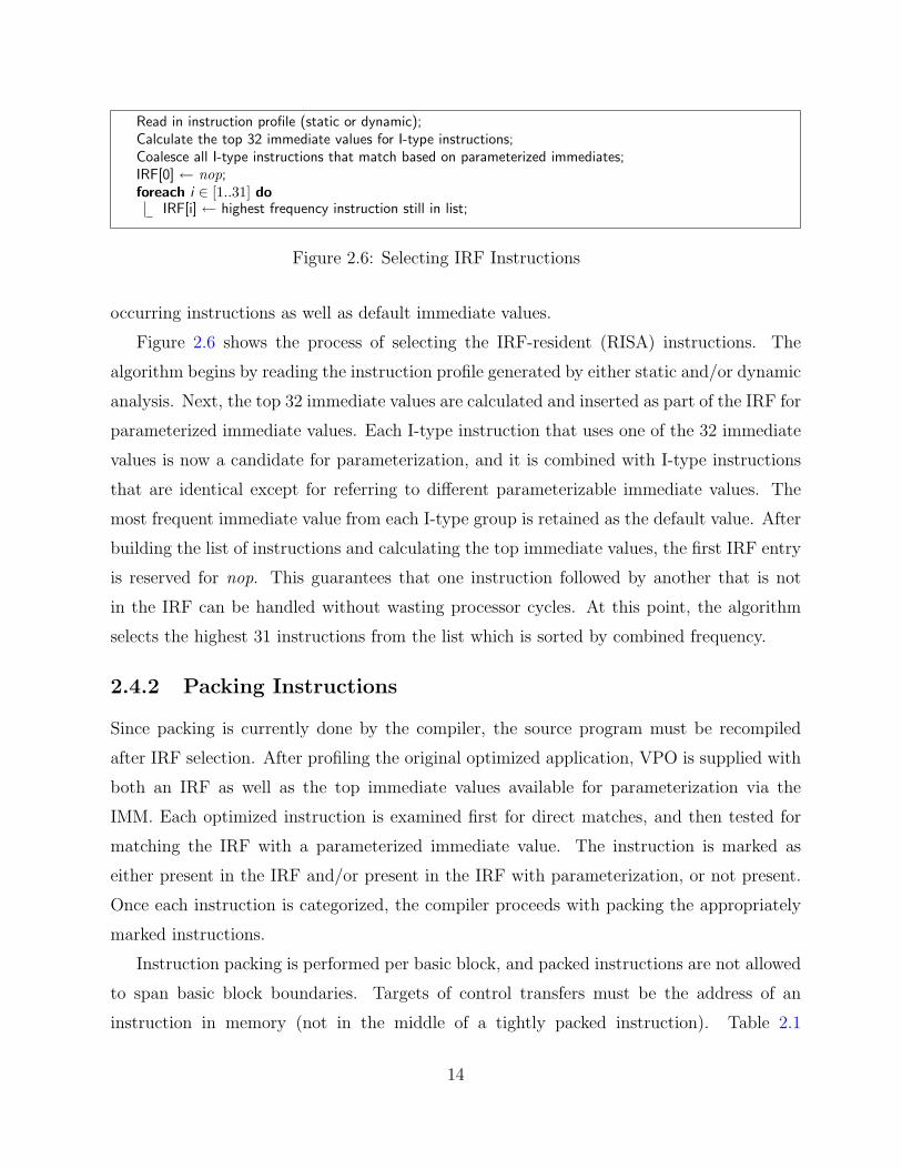
Read in instruction profile (static or dynamic);Calculate the top 32 immediate values for I-type instructions;Coalesce all I-type instructions that match based on parameterized immediates;IRF[0] ← nop;foreach i ∈ [1..31] do
IRF[i] ← highest frequency instruction still in list;
Figure 2.6: Selecting IRF Instructions
occurring instructions as well as default immediate values.
Figure 2.6 shows the process of selecting the IRF-resident (RISA) instructions. The
algorithm begins by reading the instruction profile generated by either static and/or dynamic
analysis. Next, the top 32 immediate values are calculated and inserted as part of the IRF for
parameterized immediate values. Each I-type instruction that uses one of the 32 immediate
values is now a candidate for parameterization, and it is combined with I-type instructions
that are identical except for referring to different parameterizable immediate values. The
most frequent immediate value from each I-type group is retained as the default value. After
building the list of instructions and calculating the top immediate values, the first IRF entry
is reserved for nop. This guarantees that one instruction followed by another that is not
in the IRF can be handled without wasting processor cycles. At this point, the algorithm
selects the highest 31 instructions from the list which is sorted by combined frequency.
2.4.2 Packing Instructions
Since packing is currently done by the compiler, the source program must be recompiled
after IRF selection. After profiling the original optimized application, VPO is supplied with
both an IRF as well as the top immediate values available for parameterization via the
IMM. Each optimized instruction is examined first for direct matches, and then tested for
matching the IRF with a parameterized immediate value. The instruction is marked as
either present in the IRF and/or present in the IRF with parameterization, or not present.
Once each instruction is categorized, the compiler proceeds with packing the appropriately
marked instructions.
Instruction packing is performed per basic block, and packed instructions are not allowed
to span basic block boundaries. Targets of control transfers must be the address of an
instruction in memory (not in the middle of a tightly packed instruction). Table 2.1
14

Table 2.1: Packed Instruction Types
Name Descriptiontight5 5 IRF instructions (no parameters)tight4 4 IRF instructions (no parameters)param4 4 IRF instructions (1 parameter)tight3 3 IRF instructions (no parameters)param3 3 IRF instructions (1 or 2 parameters)tight2 2 IRF instructions (no parameters)param2 2 IRF instructions (1 or 2 parameters)loose Loosely packed formatnone Not packed (or loose with nop)
summarizes the different packed instruction types that are currently available in decreasing
order of preference. The packing algorithm operates by examining a sliding window of
instructions in each basic block in a forward order. The algorithm attempts each of the pack
types in turn, until it finds a match. Packs made up of instructions only are preferred over
parameterized packs referencing the same number of instructions. The tightly packed format
supports up to five IRF entries, with any unused slots occupied by the nop located at IRF[0].
When a pack is formed, the instructions are merged into the appropriate instruction format.
The sliding window is then advanced so that the next set of instructions in the block can be
packed.
After Instruction Packing is performed on all basic blocks, packing is re-attempted for
each block containing a branch or jump that does not reside in a tightly packed instruction.
One insight that makes iterative packing attractive is the realization that branch distances
can decrease due to Instruction Packing. This decrease can cause branches or jumps that
were previously not parameterizable via the IRF to slip into the 5-bit target distance (-16
to +15). After detecting this, packing is then re-applied to the basic block. If the end result
is fewer instructions, then the new packing is kept; otherwise the branch is ignored, and the
block is restored to its prior instruction layout. Any changes that cause instructions to be
packed more densely triggers re-analysis of IRF instructions, and the process continues until
no further improvements are possible.
Figure 2.7 shows the process of packing a simple sequence of instruction. The IRF shows
five entries including nop, and the IMM includes 32 and 63 as possible values. The original
code is mapped to corresponding IRF entries, both with and without parameterization. The
15

Instruction Register File
Immediate Table
Encoded Packed Sequence
NA1NoneNA63
addu r[5], r[5], r[4]
nop0#
1234... ... ...
DefaultInstruction
...
#...34...
Value...3263
rs rt irfimmediate
opcode inst1 inst2 inst3 param s param lw r[3], 8(r[29]) {4}param3_AC {1,3,2} {3,−5}
Packed Code Sequence
lw r[3], 8(r[29])IRF[4], default (4)IRF[1], param (3)IRF[3]IRF[2], param (branch −8)
Marked IRF Sequence
lw r[3], 8(r[29])andi r[3], r[3], 63addiu r[5], r[3], 32addu r[5], r[5], r[4]beq r[5], r[0], −8
Original Code Sequence
addiu r[5], r[3], 1beq r[5], r[0], 0
andi r[3], r[3],63
opcode
lw 29
param3_AC 1
3
3 2
8
3 1 −5
4
Figure 2.7: Packing Instructions with an IRF
branch can be parameterized since -8 (instructions) can be encoded as a branch offset within
the 5-bit parameter field. Preliminary examination of the basic block reveals a non-IRF
instruction followed by a default packable IRF instruction. These two are combined into a
single loosely packed instruction. Advancing our sliding window, we see 3 IRF instructions
with two requiring parameterization. This code sequence is packed by grouping the three
instructions together as a param3 AC tightly packed instruction. The AC denotes the
instructions receiving the parameters, in this case the first and third. Note that when
packing, the branch offset is adjusted to -5, since three of the preceding instructions have
been compressed via the IRF. The breakdown of the various fields in each of the packed
instructions is also shown in the figure.
16

Table 2.2: MiBench BenchmarksCategory Applications
Automotive Basicmath, Bitcount, Qsort, SusanConsumer Jpeg, Lame, TiffNetwork Dijkstra, PatriciaOffice [Ghostscript], Ispell, Rsynth, StringsearchSecurity Blowfish, Pgp, Rijndael, ShaTelecomm Adpcm, CRC32, FFT, Gsm
2.5 Evaluation of Basic Instruction Packing
To measure the efficacy of packing instructions into registers, we selected several benchmarks
from the MiBench suite. MiBench consists of six categories of embedded software applica-
tions, each containing multiple entries. Table 2.2 shows the benchmarks used to determine
the potential benefits of using an IRF with respect to code size, energy consumption, and
execution time. The Ghostscript benchmark was used in all IRF studies except for the
compiler optimization study shown later in this chapter. These benchmarks will also be
used for evaluating our Lookahead Instruction Fetch Engine in Chapter 3. Experiments
were performed using the small input data sets, although similar results for all benchmarks
have been obtained using the large input data sets as well.
For the static code size results, an instrumented version of SimpleScalar version 3.0 is used
to collect relevant data for each benchmark [3]. Both static and dynamic profile data were
obtained from SimpleScalar. In this study, only the source code provided for each benchmark
was subjected to profiling and Instruction Packing. Library code, although linked statically
for SimpleScalar, is left unmodified.
Table 2.3 compares the instruction mix by IRF type when profiling for static code
compression versus dynamic execution. The percentages are calculated using fetches from
the IC. Thus fetching an unpacked instruction and a packed instruction are equivalent, but
the packed instruction represents more executed instructions. With dynamic profiling, we see
larger pack sizes, since we can pack many instructions from the same frequently-executed
loop bodies. Static packing can pack more instructions overall, but relies heavily on the
loosely packed format.
Figure 2.8 shows the reduction in code size for Instruction Packing with an IRF, as
well as the enhancements made. Note that these results correspond to using a static
17
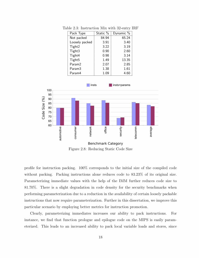
Table 2.3: Instruction Mix with 32-entry IRF
Pack Type Static % Dynamic %
Not packed 84.94 65.24Loosely packed 3.91 3.40Tight2 3.22 3.19Tight3 0.90 2.60Tight4 0.98 3.14Tight5 1.49 13.35Param2 2.07 2.85Param3 1.38 1.61Param4 1.09 4.60
Figure 2.8: Reducing Static Code Size
profile for instruction packing. 100% corresponds to the initial size of the compiled code
without packing. Packing instructions alone reduces code to 83.23% of its original size.
Parameterizing immediate values with the help of the IMM further reduces code size to
81.70%. There is a slight degradation in code density for the security benchmarks when
performing parameterization due to a reduction in the availability of certain loosely packable
instructions that now require parameterization. Further in this dissertation, we improve this
particular scenario by employing better metrics for instruction promotion.
Clearly, parameterizing immediates increases our ability to pack instructions. For
instance, we find that function prologue and epilogue code on the MIPS is easily param-
eterized. This leads to an increased ability to pack local variable loads and stores, since
18

the corresponding instructions are already available in the IRF and the IMM can supply
necessary parameters. Additionally, the IMM allows us exploit simple transformations for
increasing the redundancy of semantically equivalent operations.
A modified version of the sim-panalyzer simulator is used to gather the energy consump-
tion data for the benchmarks in this study [69]. Sim-panalyzer calculates approximations
of area size and number of gates for each component and ties these numbers to the cycle-
accurate simulation provided via SimpleScalar. We modified the original Alpha port of
sim-panalyzer to match the MIPS. The resulting energy estimates are not exact, but are
accurate enough to support our claims.
The energy savings come from two sources. First, applications can complete in fewer
cycles due to the increased fetch rate that the IRF provides. Second, there are fewer accesses
to the IC and memory as approximately 55% of instructions are fetched from the IRF. An
access to the IC has an approximately two orders of magnitude higher energy cost than an
access to a register file. A memory access is approximately another two orders of magnitude
more costly than an IC hit. Additionally, subsequent fetches from the IRF need not access the
ITLB, branch predictor, branch target buffer, or return address stack, since these components
still operate at the MISA level only.
Figure 2.9 shows the energy consumed during instruction fetch compared to the unpacked
versions of the programs. On average, we obtain a 37% reduction in energy consumed by
instruction fetch. Much of this savings comes from a reduction in number of IC references,
with additional savings from a reduction in IC misses for some of the network and automotive
applications and a reduction in execution time for the security applications. For these
applications, instruction fetch energy comprises 30% to 45% of the total power requirements.
In most benchmarks, the improvements in execution time are minimal, with most
programs executing in 98% to 100% of the original number of cycles. Average execution
time savings was 5.04%, due primarily to three of the security benchmarks: blowfish, pgp
and rijndael executed in 59%, 61% and 67%, respectively, of their original cycles. After
Instruction Packing, the working set of these applications fits better into cache, and they
have far fewer IC misses. The performance gains, though small for many of the benchmarks,
also allow the programs to finish in fewer cycles, and this contributes to the overall energy
reduction. Although the collected measurements are for fetch energy, the fetch power
consumption results are similar for 5 of the 6 categories, since the execution times are
19

Figure 2.9: Reducing Fetch Energy/Exec. Time
approximately the same. Due to the improved execution time of many security benchmarks,
their fetch power savings would be proportionally lower than their overall fetch energy
savings.
2.6 Improving IRF Utilization via RegisterWindowing
The IRF has also been extended to support additional availability of instructions, both
through software and hardware [31]. As with other techniques, increasing the size of the IRF
yields diminishing returns. The IRF is energy efficient because it is smaller and less complex
than an instruction cache. Code size is reduced because the IRF specifiers can be packed
together effectively. If we increase the addressable area in the IRF, it will require greater
energy to operate, and may possibly need to use less efficient RISA encodings. Software
windowing seeks to change the IRF contents dynamically on function calls and returns,
while hardware windowing attempts to cut back on some of the overhead due to software
windowing.
20

2.6.1 Software Windowing
The baseline IRF architecture assigns the IRF-resident instructions at load-time for the
duration of the application’s execution. Since the instructions in the IRF were unchanged by
the application during execution, the benefits of the IRF could be reduced if the application
has phases of execution with radically different instruction composition [68]. No individual
phase will be able to achieve optimal packing with a single statically loaded IRF, since only
the most frequently executed instructions from each phase will exist in the IRF. A natural
extension to improve IRF utilization is to enable the modification of instructions in the IRF
during program execution. This will facilitate a better selection of instructions for each phase
of the program execution. One approach for handling varied phase behavior is to extend the
architecture with load irf instructions and have the compiler promote instructions to the
IRF at run-time. This approach is similar to data register promotion via register allocation.
IRF contents at a particular execution point can be viewed as an IRF window, and each
function could logically place some set of instructions into the window. These windows could
even be shared amongst several functions to reduce the switching costs necessitated by call
and return instructions.
Functions are natural entities to allocate to windows since they are compiled and analyzed
separately. Earlier work on exploiting instruction registers used the entire execution profile
to decide which instructions would be allocated to the IRF for the entire execution. In
effect, one can view the prior work as allocating all of the functions to a single window.
When multiple windows are available, we must decide how to partition the set of functions
in a program among these windows. The goal is to allocate functions whose set of executed
instructions are similar to the same window so that the windows can be best exploited.
Instructions can be inserted that load an individual IRF entry from memory. Thus,
there will be a cost associated with switching IRF windows. To assess how effective this
approach can be, we devised an algorithm that takes into account the cost of switching the
instructions available via the IRF. This algorithm is shown in Figure 2.10. We first profiled
each application to build a call graph with edges weighted by the total number of calls
between each pair of functions. Initially all functions start as part of a single IRF window.
We apply a greedy approach to adding partitions, selecting the most beneficial function to
be either placed in a new partition of its own or merged with another existing partition.
21

Read in instruction profile for each function;Read in callgraph along with estimated edge weights;Merge all functions into a single IRF window;changes = TRUE;while changes do
changes = FALSE;best savings = 0;split type = NONE;foreach function i that has not been placed do
new savings = benefit of placing i in a new window; // 1) Find maximum benefit split,if new savings > best savings then
best savings = new savings;split function = i;split type = NEW WINDOW;
foreach function i that has not been placed doforeach window k from 1 to n-1 do
new savings = benefit of placing i in window k; // 2) Find maximum benefit mergeif new savings > best savings then
best savings = new savings;split function = i;split window = k;split type = ADD TO WINDOW;
if best savings > 0 thenif split type == NEW WINDOW then
create a new window n and move split function into it; // 3a) Perform the split,n += 1;
else//split type == ADD TO WINDOWmove split function into split window; // 3b) Or perform the merge
changes = TRUE;mark split function as placed;
Figure 2.10: Partitioning Functions for Software IRF Windows
The goal of this algorithm is to keep functions in the same window unless the benefit for
switching windows outweighs the cost of additional instructions to load and restore IRF
windows. Each time we calculate the cost of allocating a function to a specific window, we
also include the switching cost if the function being allocated either invokes or is invoked by
a function in a different window. We determine the difference in IRF entries between the two
windows and assess the cost of loading the instructions for the new window at the point of
the call and loading the instructions for the old window at the point of the return. One can
view this cost as a lower bound since it may be difficult to keep the common instructions in
the same IRF entry locations since a function may be invoked by many other functions using
22

different windows. Additionally, we only place each function in a partition at most one time
in order to reduce the partitioning overhead. Once the partitions have been constructed, the
compiler determines which instructions can be packed and at what call sites IRF loads must
occur to maintain the correct contents of the IRF.
Using a modified SimpleScalar simulator, we evaluated the effectiveness of applying
a software partitioning against the single statically allocated IRF. Figure 2.11 shows the
results for performing software partitioning on each benchmark. Each benchmark is shown
individually along with the averages for each category and the entire suite. The software
window approach obtains an average fetch cost of 54.40% compared to not using an IRF,
while the original single IRF only obtains 58.08%. Several of the benchmarks perform worse
after packing instructions with software windows. This is due to the heuristic used for
choosing which instructions to pack. In the single IRF case, only the extremely frequent
instructions from tight loops become packed, leading to a great initial savings. This is
particularly true for the applications with a few dominant loops. The greedy heuristic used
to partition the functions can underestimate the overhead of a function removed from the
primary partition early in the processing because it assumes that unprocessed functions will
not increase the overhead. Of course some of these later functions will be placed in different
partitions increasing the overhead. The smaller the benefit of partitioning, as seen in some
of the smaller applications, the more likely inefficiencies in the heuristic will negate the
advantage of performing IRF partitioning. The larger benchmarks see marked improvement
(up to 31% savings with Lame), as they are more likely to exhibit different phases of execution
and can better partition their phase behavior using multiple IRF windows.
The number of software partitions allocated for each benchmark ranges from 1 through
32 (Pgp) with a median of only 4 and a mean of 8.33. The relatively small number of
partitions reduces the overhead of loading instructions into the IRF by reducing the number
of function calls that require a new set of instructions placed into the IRF. Each call site may
also only change a subset of the IRF entries since the IRF windows may contain some of the
same instructions. In fact, the average number of IRF entries that differ between partitions
is 24.54, so the overhead for each function call between different IRF partitions averages 49
new instructions — half each for allocating the new instruction and restoring at the function
return. The small number of partitions also allows us to consider a hardware solution that
can eliminate most of the overhead of loading a single IRF in favor of providing multiple
23
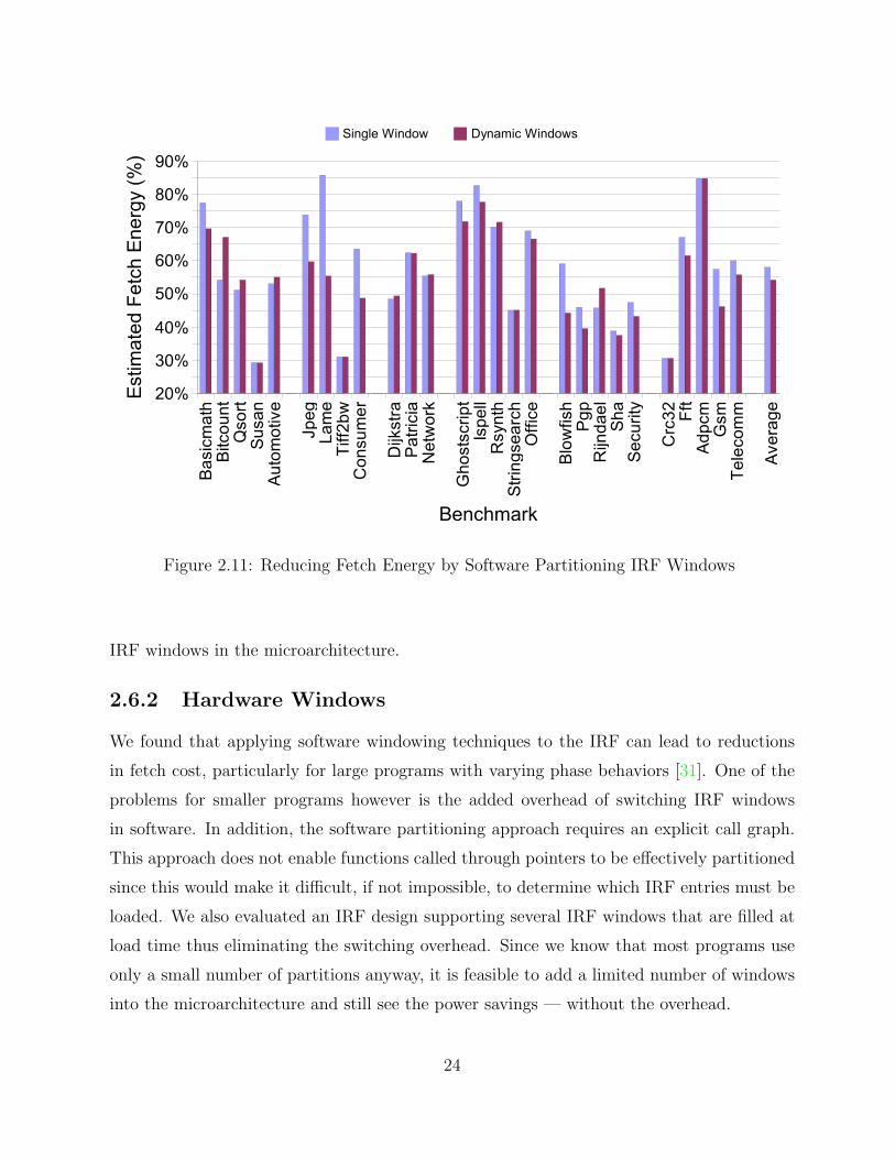
Figure 2.11: Reducing Fetch Energy by Software Partitioning IRF Windows
IRF windows in the microarchitecture.
2.6.2 Hardware Windows
We found that applying software windowing techniques to the IRF can lead to reductions
in fetch cost, particularly for large programs with varying phase behaviors [31]. One of the
problems for smaller programs however is the added overhead of switching IRF windows
in software. In addition, the software partitioning approach requires an explicit call graph.
This approach does not enable functions called through pointers to be effectively partitioned
since this would make it difficult, if not impossible, to determine which IRF entries must be
loaded. We also evaluated an IRF design supporting several IRF windows that are filled at
load time thus eliminating the switching overhead. Since we know that most programs use
only a small number of partitions anyway, it is feasible to add a limited number of windows
into the microarchitecture and still see the power savings — without the overhead.
24
...
IRF windows
functions
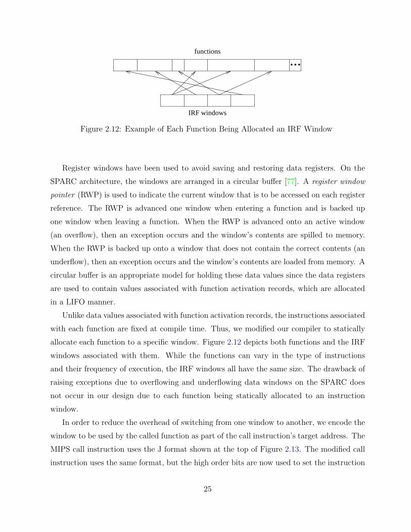
Figure 2.12: Example of Each Function Being Allocated an IRF Window
Register windows have been used to avoid saving and restoring data registers. On the
SPARC architecture, the windows are arranged in a circular buffer [77]. A register window
pointer (RWP) is used to indicate the current window that is to be accessed on each register
reference. The RWP is advanced one window when entering a function and is backed up
one window when leaving a function. When the RWP is advanced onto an active window
(an overflow), then an exception occurs and the window’s contents are spilled to memory.
When the RWP is backed up onto a window that does not contain the correct contents (an
underflow), then an exception occurs and the window’s contents are loaded from memory. A
circular buffer is an appropriate model for holding these data values since the data registers
are used to contain values associated with function activation records, which are allocated
in a LIFO manner.
Unlike data values associated with function activation records, the instructions associated
with each function are fixed at compile time. Thus, we modified our compiler to statically
allocate each function to a specific window. Figure 2.12 depicts both functions and the IRF
windows associated with them. While the functions can vary in the type of instructions
and their frequency of execution, the IRF windows all have the same size. The drawback of
raising exceptions due to overflowing and underflowing data windows on the SPARC does
not occur in our design due to each function being statically allocated to an instruction
window.
In order to reduce the overhead of switching from one window to another, we encode the
window to be used by the called function as part of the call instruction’s target address. The
MIPS call instruction uses the J format shown at the top of Figure 2.13. The modified call
instruction uses the same format, but the high order bits are now used to set the instruction
25

opcode
6 bits
target address
26 bits
opcode actual target addresswindow
Figure 2.13: Encoding the IRF Window Number As Part of the Call Target Address
RWP (IRWP) and only the low order bits are used to update the program counter. While
this change does decrease the maximum size of programs from 226 instructions, even retaining
only 20 bits for the actual target address would allow over two million (now more compressed)
instructions, which should be more than enough for almost all embedded applications.
Rather than just saving the return address in a data register ($31 on the MIPS), the call
instruction also saves the value of the current IRWP. Thus, the semantics of the return
instruction, jr $31 on the MIPS, is also changed to reset the IRWP. The processor has
an entire cycle during each call and return instruction to set the IRWP. Note that calls
through pointers can also be handled since the linker can modify the address associated with
a function so that the high order (or low order) bits indicate which window is associated
with the function.
Figure 2.14 shows the IRF system diagram completed with hardware support for register
windows. It is important to note that only the IRF is windowed. The IMM remains a
single 32-entry table for commonly used immediate values across the entire application.
Rather than having to go through an IRWP for every access to an entry in the IRF, the
hardware could alternatively copy the registers each time the window is changed during the
execution of a call or return instruction. Parallel register moves can be performed between
the IRF and the appropriate window, which is similar to the boosting approach used to
support speculation by copying a number of shadow registers to general-purpose registers in
parallel [71].
Register windows are a more attractive approach than just increasing the number of total
available registers for hardware such as the IRF. First, increasing the number of registers
in the IRF without windowing would force the RISA instruction specifiers to grow beyond
the 5 bits they currently occupy. Moving to 64 entries would require 6 bits, from which it
would not be possible to pack 5 entries together (6 + 5 × 6 = 36 bits > 32 bits). Thus, at
most 4 RISA instructions could exist in a tightly packed instruction, limiting the number
26

IF Stage
InstructionCachePC
(ROM or L1)
IF/ID
First Half of ID Stage
IRWP
MultipleIRF
Windows
IMM
Figure 2.14: Instruction Register File with Hardware Windowing
of pure IRF fetches that can possibly be attained. Prior research shows that 13.35% of the
dynamic instructions fetched from the IC are these very tightly packed instructions [28], so
cutting them down to four entries might drastically affect the fetch performance. Second,
the larger IRF would also consume more power as the entirety would need to be active on
each instruction decode. With windowing, some portions can be placed in a low-power state
when they are not being actively used.
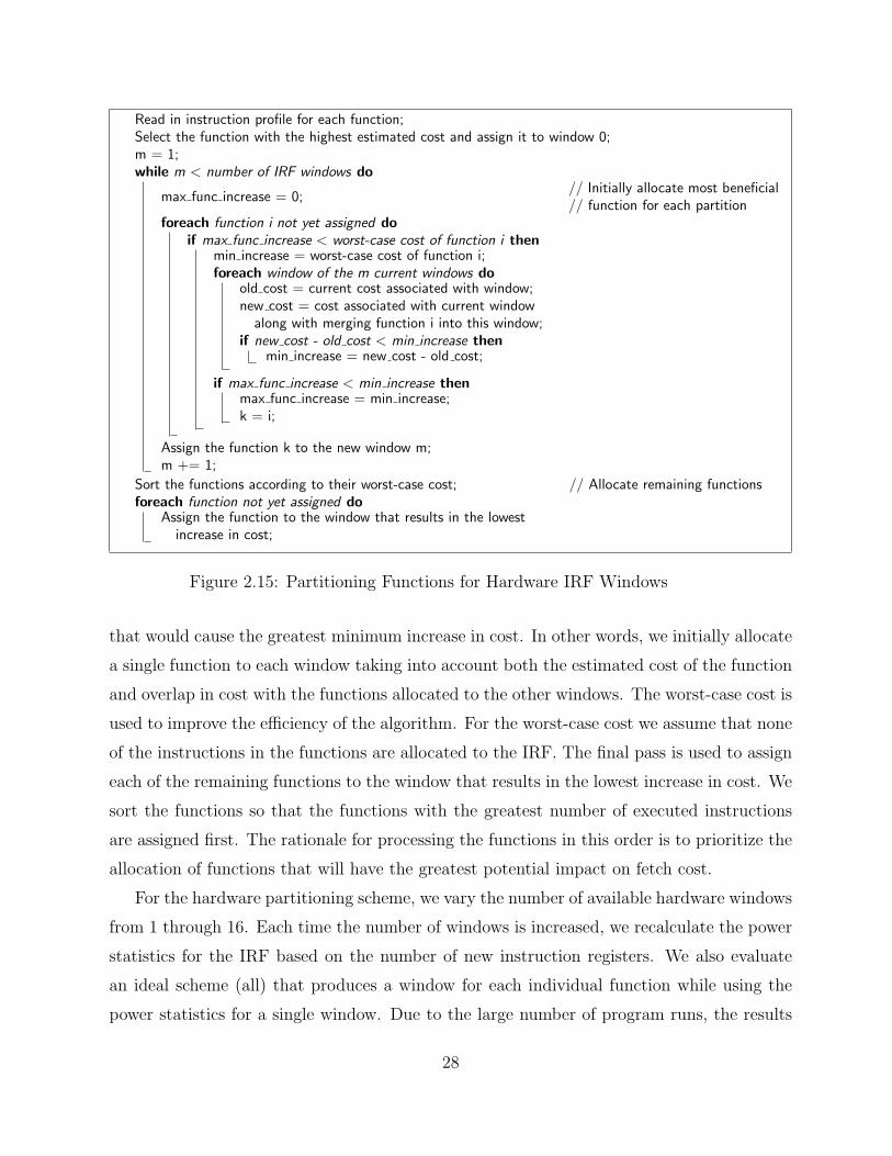
Figure 2.15 depicts the algorithm that we used to perform this partitioning. The primary
difference between this heuristic and the previous software partitioning heuristic is that this
version does not need to estimate overhead costs. The algorithm begins by reading in the
instruction profile that indicates how often each type of instruction is executed for each
function. We are concerned with the type of instruction since we are able to parameterize
immediate values so that several distinct instructions can refer to the same RISA instruction.
The algorithm then estimates a cost for each function, where the 31 most frequently executed
types of instructions have a fetch cost of 1 and the remaining instructions have a fetch cost
100 times greater, which serves as a simple estimate for the relative difference in energy
consumption from fetching an instruction from the IRF versus the IC. The 31 most frequently
executed types of instructions are selected since one of the 32 entries in the IRF has to be
reserved to represent a nop (no operation) when not all of the RISA instruction fields in a
packed instruction can be filled, allowing a portion of the fields to be used without wasting
processor cycles. For each of the remaining windows the algorithm determines for each
function the minimum increase in cost that would be required to assign that function to one
of the currently allocated windows. The algorithm allocates the next window to the function
27
Read in instruction profile for each function;Select the function with the highest estimated cost and assign it to window 0;m = 1;while m < number of IRF windows do
max func increase = 0;// Initially allocate most beneficial// function for each partition
foreach function i not yet assigned doif max func increase < worst-case cost of function i then
min increase = worst-case cost of function i;foreach window of the m current windows do
old cost = current cost associated with window;new cost = cost associated with current window
along with merging function i into this window;if new cost - old cost < min increase then
min increase = new cost - old cost;
if max func increase < min increase thenmax func increase = min increase;k = i;
Assign the function k to the new window m;m += 1;
Sort the functions according to their worst-case cost; // Allocate remaining functionsforeach function not yet assigned do
Assign the function to the window that results in the lowestincrease in cost;
Figure 2.15: Partitioning Functions for Hardware IRF Windows
that would cause the greatest minimum increase in cost. In other words, we initially allocate
a single function to each window taking into account both the estimated cost of the function
and overlap in cost with the functions allocated to the other windows. The worst-case cost is
used to improve the efficiency of the algorithm. For the worst-case cost we assume that none
of the instructions in the functions are allocated to the IRF. The final pass is used to assign
each of the remaining functions to the window that results in the lowest increase in cost. We
sort the functions so that the functions with the greatest number of executed instructions
are assigned first. The rationale for processing the functions in this order is to prioritize the
allocation of functions that will have the greatest potential impact on fetch cost.
For the hardware partitioning scheme, we vary the number of available hardware windows
from 1 through 16. Each time the number of windows is increased, we recalculate the power
statistics for the IRF based on the number of new instruction registers. We also evaluate
an ideal scheme (all) that produces a window for each individual function while using the
power statistics for a single window. Due to the large number of program runs, the results
28
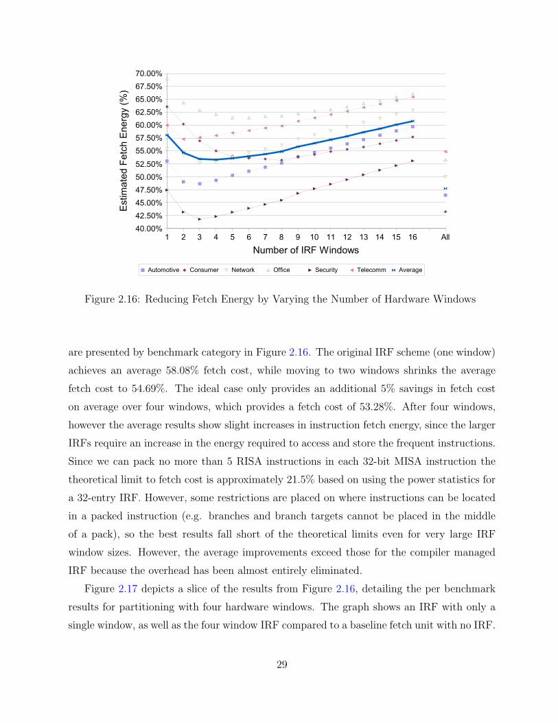
Figure 2.16: Reducing Fetch Energy by Varying the Number of Hardware Windows
are presented by benchmark category in Figure 2.16. The original IRF scheme (one window)
achieves an average 58.08% fetch cost, while moving to two windows shrinks the average
fetch cost to 54.69%. The ideal case only provides an additional 5% savings in fetch cost
on average over four windows, which provides a fetch cost of 53.28%. After four windows,
however the average results show slight increases in instruction fetch energy, since the larger
IRFs require an increase in the energy required to access and store the frequent instructions.
Since we can pack no more than 5 RISA instructions in each 32-bit MISA instruction the
theoretical limit to fetch cost is approximately 21.5% based on using the power statistics for
a 32-entry IRF. However, some restrictions are placed on where instructions can be located
in a packed instruction (e.g. branches and branch targets cannot be placed in the middle
of a pack), so the best results fall short of the theoretical limits even for very large IRF
window sizes. However, the average improvements exceed those for the compiler managed
IRF because the overhead has been almost entirely eliminated.
Figure 2.17 depicts a slice of the results from Figure 2.16, detailing the per benchmark
results for partitioning with four hardware windows. The graph shows an IRF with only a
single window, as well as the four window IRF compared to a baseline fetch unit with no IRF.
29

Figure 2.17: Reducing Fetch Energy with a 4 Partition IRF
Although a few of the benchmarks see a small increase in fetch energy when moving to four
windows, there is still a substantial overall fetch energy savings, and the additional partitions
can be used to improve more phase-diverse benchmarks like Jpeg and Blowfish. Many of the
benchmarks are able to obtain a large benefit from the hardware IRF windows since they
have a diverse instruction composition among several frequently accessed functions. The
hardware partitioning allows function call and return switching costs to be eliminated in
these cases, leading to improved packing density and reduced fetch cost. However, a few of
the applications (Lame) do not achieve the same savings as the compiler managed IRF when
the number of IRF windows is smaller than the partitions used in the results for software
partitioning.
30
2.7 Increasing Packing Levels with CompilerOptimizations
Prior research used dynamic profile data to determine the most frequently accessed instruc-
tions and made minor changes to the instruction selection heuristics in the compiler. This
approach enabled the IRF to significantly improve code size as well as energy consumption,
but since the instruction selection, register allocation, and code scheduling transformations
used in the compiler were not tuned to the requirements of an IRF architecture, there was
still room for improvement.
Prior enhancements to the IRF have been primarily architectural in nature, and would
be more difficult to address from the compiler perspective. Yet there still exist several
limitations that can potentially be addressed by compiler optimizations. Our initial packing
algorithms focused primarily on the dynamic behavior of an application in an effort to
minimize fetch energy [31, 30]. The static composition of an application should also be
accounted for when promoting instructions to the IRF, as code size can have a significant
impact on the memory architecture of an embedded system. For an instruction to be
promoted to the IRF, the opcode and all operands must match exactly. Parameterization
provides a partial solution for capturing additional instructions, but the compiler can
intelligently seek out even more cases where register operands can be modified to allow
an instruction to be packed. Additionally, the order of instructions in a basic block can
artificially limit the packing density, since packable instructions work best when they are
adjacent. Non-packable instructions impose similar limitations, effectively dividing our
ability to pack instructions in a basic block. Finally, there are several artificial limitations
on forming packs of instructions. For example, in previous implementations, any packed
branch instruction had to occupy the final slot of the packed instruction, as packs were not
allowed to span basic block boundaries. Each of these limitations can be effectively attacked
with detailed compiler analyses and transformations [33]. In fact, effective use of the IRF is
more dependent on well-tuned compiler optimizations than a more conventional architecture.
Also, the IRF approach provides some unique opportunities for code optimization that are
counter-intuitive to those familiar with more conventional processor designs.
This section will describe several modifications that we have made to the Instruction
Packing process. These enhancements include more accurately modeling the benefit of
31

promoting an instruction, allowing additional I-type instructions to be promoted with
different default immediate parameters, and integrating static and dynamic measures for
selecting the instructions to promote. Mixed profiling allows a developer to fine-tune the
characteristics of an application across several design constraints including static code size
and overall processor energy consumption. We have also adapted existing optimizations
for instruction selection, register re-assignment, and instruction scheduling to enhance the
compiler’s ability to pack instructions together. Each of these enhancements is evaluated
with a 4 hardware window IRF with parameterization support. The results show that these
optimizations can significantly reduce both the static code size and energy consumption of
an application, while providing a slight performance improvement.
2.7.1 Improving Instruction Promotion
Instruction promotion is the process of selecting which instructions should reside in each
IRF window, as well as which immediate values should reside in the IMM. This process of
promotion has been performed offline by supplying static or dynamic profile data to irfprof,
an IRF selection and layout tool [31]. Functions are partitioned and placed into static IRF
windows by irfprof according to a greedy algorithm that has been previously explored. This
algorithm operates by estimating the potential cost/benefit of packing the instructions of a
function into each particular IRF window, and then greedily selecting the most beneficial
function to assign to a window until each function has been allocated.
In the original irfprof, IRF-resident instructions were evaluated as having a cost of 1, while
non-resident instructions had a cost of 100. These costs were chosen based on the relative
energy benefit of placing an instruction into the IRF versus keeping it in the instruction cache.
However, not all instructions will obtain equal benefits from being promoted to the IRF.
Parameterizable I-type instructions were originally coalesced together with the most frequent
immediate value becoming the default immediate, while each individual parameterizable form
of the instruction contributed to the overall benefit for promoting this instruction. However,
the benefit of immediate instructions that require a parameter should be lower, since they
will occupy two slots of a MISA instruction, thus making them impossible to loosely pack.
To remedy the over-promotion of I-type parameterizable instructions, we can more
accurately reflect the benefit of promoting an instruction by examining what has already
occurred during the selection. The benefit of promoting to the IRF can be modeled more
32

accurately by quantifying the possible potential improvement. For instance, a tightly
packed instruction cannot achieve any further benefit, so its potential improvement is 0.
A parameterized packable instruction (one which has to use the IMM) has a potential
improvement of 1, since it could be promoted with its immediate value as the default.
A loosely packable instruction has a potential improvement of 3, since it normally would
occupy approximately 4 of the slots in a MISA instruction, with the remaining slot available
for a single RISA reference. Finally, an instruction that is not loosely packable like lui has a
potential improvement of 4, since packing it into a single RISA entry will free up 4 additional
slots in the MISA instruction. By calculating the potential improvements in this manner,
we provide a means for multiple I-type instructions that differ only in default immediate
value to reside in the IRF simultaneously. This allows each entry to remain loosely packable,
which can be beneficial if each operation occurs very frequently.
In all prior IRF work, instructions have been promoted to the IRF based purely on static
or dynamic profile data. Although the IRF is designed to improve the overall efficiency
of instruction fetch, this division may not produce an adequate balance between code
size savings and energy reduction, particularly when dealing with the highly constrained
embedded design space. Dynamic profiling exposes the kernel loops of the application, and
correspondingly the most frequently executed instructions from these loops. The static profile
will likewise reveal those instructions that comprise the greatest portion of the application’s
code. Using only a dynamic profile could suppress the promotion of common function
prologue and epilogue code, since many functions may never be executed during the training
run. Similarly, static profiling will not be able to obtain the fetch energy benefits of packing
instructions together from the application’s most frequently executed tight loops. A unified
approach encompassing static and dynamic measures may yield a majority of the benefits of
each, resulting in a more suitable packing strategy for the embedded domain. The promotion
algorithm can be modified to incorporate the scaling of both the static and dynamic profile
data to provide such flexibility.
2.7.2 Instruction Selection
Instruction selection is the process by which a compiler chooses which instruction or
instruction sequence to use for a particular semantic operation. The VPO compiler operates
on register transfer lists (RTLs) that have a one-to-one correspondence with machine
33

instructions. We can modify instruction selection to increase the amount of redundancy
in the code without negatively impacting code size or performance. There are several
methods for using instruction selection in this manner. First, we can choose equivalent
parameterizable operations to replace simple operations, such as encoding move operations
as additions with 0. Second, commutativity rules can be applied to make sure that all
semantically equivalent instruction instances use the same order for operands. Third, we
can apply parameterization to the destination registers of R-type instructions, which were
previously unable to be parameterized.
Choosing equivalent parameterizable instructions over simple instructions is a technique
that has previously been applied to instruction packing [28]. In this dissertation, we
quantify the exact benefits of these transformations in increasing the instruction redundancy
within an application. Most of these equivalence transformations occur for the mov and li
pseudo-instructions. Register moves are normally performed using the addu instruction
with the hard-wired register zero as the second source argument. Instruction selection
instead generates this operation as an addiu instruction with zero as the immediate operand.
Load immediate instructions with small constants can interchangeably be generated as addiu
instructions or ori instructions that use register zero as their first source operand. To increase
code redundancy, the profiling pass always converts these instructions to an addiu format.
Each of these transformations increase the number of opportunities that parameterization
will have for packing various sequences of instructions.
Simple transformations can also be used to increase redundancy by reducing or completely
eliminating instruction diversity. The native MIPS ISA uses PC-relative addressing for
branches and absolute addressing for jumps. Absolute addressing poses problems with
Instruction Packing, since there can be quite a diverse set of jump target addresses. To
increase the ability for frequent jumps to be placed in the IRF, short distance jumps (-16
to +15 instructions) are converted into branches that compare register zero to itself. These
instructions can then be parameterized in the same manner as conditional branches. If short
distance jumps occur frequently in the application, then only a single RISA entry is necessary
to parameterize each of them.
The prior ISCA work also applied transformations to place operands for commutative
operations in the same order for each instruction. If the destination register is also a source
register, then that register is placed first in the operand list. If all registers are different,
34

then the operands are ordered from lowest to highest number. This transformation unifies
equivalent commutative operations in an attempt to further increase the level of instruction
redundancy.
Similar to our enhancement for frequently occurring immediate values, simple parame-
terization can be extended for R-type destination registers as well. This works similarly to
traditional IRF parameterization, consuming an additional RISA slot in the tightly packed
instruction format to specify the replacement value (5 bits) for rd. It is important to note
that the requirements for supporting this feature are minimal, as the existing parameterized
instructions will not require any modifications. Only a small amount of additional hardware
is necessary, primarily in the form of multiplexers going to the instruction decoder.
2.7.3 Register Re-assignment
Compilers often attempt to minimize register usage in order to keep additional registers
available for further optimizations. Since the VPO compiler applies optimization phases
repeatedly, it also rigorously attempts to minimize the number of distinct registers used in
each particular function. This strategy can clearly lead to different register usage patterns
in the generated code for similar but slightly different functions due to the varying register
pressure. A small difference in register numbering can eliminate the possibility of Instruction
Packing for a sequence of instructions. Although the IRF supports a limited ability to
parameterize registers, register re-assignment can be beneficial by replacing entire register
live ranges. With re-assignment, these registers can be adjusted to match existing IRF
instructions, leading to increased pack density.
Optimizing compilers have employed register renaming to eliminate anti-dependences in
generated code [58, 76]. Anti-dependences restrict the scheduling of instructions for an in-
order pipeline, and can also negatively affect the issue of instructions in out-of-order pipelined
architectures. It is for this reason that many modern out-of-order architectures employ
additional hardware register renaming techniques to eliminate anti-dependences. Rather
than renaming for avoidance of anti-dependences, we will focus on re-assigning registers to
make instructions match existing IRF entries when possible.
Although compiler register renaming algorithms often operate within basic blocks to
keep compile time fast, IRF register re-assignment will use a register interference graph
to calculate the entire inter-block live range span for each register. When constructing
35

the register interference graph, registers that are used and set within a single RTL will be
split into two distinct live ranges. This splitting allows us to re-assign registers in a more
fine-grained manner than the merging of these live ranges would have allowed. Shorter
live ranges have reduced potential for conflicts, which can limit the effectiveness of such a
transformation.
We use a greedy algorithm for selecting the candidates for register re-assignment. Basic
blocks are ordered from most frequently executed to least frequently executed based on
dynamic profiling data. With this information, we go through each potential re-assignment
individually. Live ranges of registers that cannot be altered (e.g. calling conventions) are
marked so they are not re-assigned in any manner. Since we are not going to perform multiple
renames simultaneously, we must verify that the target register to which we are attempting
to re-assign is not live at any adjacent node in the graph. Using the register interference
graph, we can now perform the register substitution on the appropriate portion of each given
RTL. Note that we cannot change all references, since we are splitting uses and sets within
a single RTL into multiple live ranges of the same register number.
Figure 2.18 shows an example of register re-assignment. The code is a single loop with an
if statement guarding two store instructions. Column A shows the component instructions in
the code sequence along with relevant data regarding the IRF entry numbers of the packable
instructions. The overall packing of the entire loop, assuming that no other transformations
are applied, is shown in column B. If register re-assignment is performed on the code, then
we obtain the code shown in column C. The last column (D) shows the re-assigned code
after packing the instructions. The result is that the first two blocks of the original loop
that required five MISA instructions can now be accomplished in two MISA instructions.
2.7.4 Instruction Scheduling
Instruction scheduling is a traditional compiler optimization that reorders the instructions
in a basic block in an attempt to eliminate pipeline stalls due to long operation dependences.
The actual scheduling often employs a directed acyclic graph (DAG) to maintain instruction
dependence relationships. Instructions that read a particular register/memory must wait for
all preceding writes to that register/memory. Instructions that write to a register/memory
must wait until all prior reads and writes to that register/memory have occurred. Once
the DAG is constructed, instructions are issued based on priorities relating to future
36

A) Instructions B) Packed Instructions C) Re-assigned Instructions D) Packed Instructions.L164: .L164: .L164: .L164:lw $8,0($14) # lw $8,0($14) {2} lw $2,0($14) # IRF (1) param4d{1,2,3,4,.L165}lw $3,0($12) # IRF (2) lw $3,0($12) # IRF (2)slt $1,$3,$8 # slt $1,$3,$8 slt $1,$3,$2 # IRF (3)beq $1,$0,.L165 # IRF (4) + beq $1,$0,.L165 beq $1,$0,.L165 # IRF (4) +
# IMM (.L165) # IMM (.L165)sw $3,0($14) # sw $3,0($14) sw $3,0($14) # sw $3,0($14) {7}sw $8,0($12) # sw $8,0($12) sw $2,0($12) # IRF (7).L165: .L165: .L165: .L165:... ... ... ...bne $1,$0,.L164 # bne $1,$0,.L164 bne $1,$0,.L164 # bne $1,$0,.L164
Figure 2.18: Register Re-assignment
dependences. Instructions that have no incoming arrows in the DAG are considered to
be in the ready set, as they have no dependences on which to wait.
Packing multiple RISA instructions into a single MISA instruction is somewhat similar to
very-long instruction word (VLIW) scheduling. VLIW machines issue groups of instructions
that must satisfy many other dependencies as well. These VLIW instructions are often
constrained by the number and type of different operations allowed in a single word. For
instance, a single VLIW instruction might be limited to only one memory store operation
if there is only a single memory functional unit available during each cycle. In addition to
physical hardware constraints, the instructions in the word are executed simultaneously,
so dependences have to be placed in different VLIW words, leading to a great deal of
fragmentation. Scheduling for IRF is similar to VLIW instruction scheduling, but the
primary difference is that dependent instructions can be packed together in a single pack,
since the individual RISA references will still be sequentially issued.
Figure 2.19 shows the algorithm for scheduling IRF instructions within a basic block.
This greedy algorithm is based on several heuristics for producing dense sequences of packed
instructions. It is invoked iteratively using the ready set until all instructions have been
scheduled for the current block. It is important to note that the ready set from which
selection occurs is sorted with respect to minimizing stalls due to instruction dependences.
Thus, the dependence between instructions often acts as the tie-breaker for selecting which
IRF or non-IRF instruction should be scheduled next. Priority is primarily given to loose
packs between instructions that do not exist in the IRF and tightly packable RISA references.
If three or more RISA reference slots (both IRF instructions and parameters) are available,
37

if blk→slots == 0 thenif blk→prev packable and an IRF insn is in ready set then
issue the IRF insn next
else if 3 or more IRF slots are in ready set thenissue an IRF param or IRF insn next
else if IRF insn and packable insn are in ready set thenissue a loose pack with the packable insn and the IRF insn
if no instructions have been chosen for issue yet thenif (blk→prev packable or blk→slots == 4) and an IRF insn exists in ready set then
issue the IRF insn next
else if 1 ≤ blk→slots ≤ 3 and any IRF insns in ready set thenissue an IRF param or IRF insn next
else if A non-IRF insn exists in ready set thenissue the non-IRF insn
elseissue the first IRF param or IRF insn next
Update blk→prev packable and blk→slots based on the issued instruction(s)
Figure 2.19: Scheduling Instructions for a Basic Block
then a tightly packed instruction will be started instead. When issuing into a started tightly
packed instruction, we always attempt to issue the parameterized references first, since they
require two slots and are unable to be loosely packed. If we cannot issue into a loose pack or a
tight pack, then we attempt to issue non-IRF instructions next. This allows us to potentially
free up dependent IRF instructions for packing on future iterations. Finally, we issue IRF
instructions if there are no ready non-IRF instructions. After choosing an instruction or
instruction sequence for issue, the prev packable and slots fields in the basic block structure
must be updated appropriately.
Figure 2.20 shows the breakdown of instruction types used in the diagrams for the
remainder of this section. Colored boxes refer to used portions of the instruction format.
Empty boxes denote unused RISA slots. Non-packable refers to instructions that cannot
support a loosely packed RISA reference and are not available via the IRF themselves (e.g.
jal). A non-packable instruction occupies the space for all 5 RISA slots, and so there are
none available for packing. Loosely packable refers to an instruction that is not available
via the IRF, but has additional room for a RISA reference. These instructions occupy 4
of the 5 RISA slots, and so can accept a single non-parameterized IRF instruction. The
parameterized tightly packable instruction is one that is available via a combination of the
IRF and parameterization. The parameter can refer to an entry in the IMM table, a short
38

������������
������������
������������
������������
������������������
������������������
��������������������������������������������������������������������������������
��������������������������������������������������������������������������������
Legend
(In IRF with parameter)Parameterized Packable
(In IRF)Tightly Packable
(Not in IRF)Loosely Packable
Non−packable
Figure 2.20: Instruction Scheduling Legend
������������
������������
������������
������������
������������������
������������������
��������������������������������������������������������������������������������
��������������������������������������������������������������������������������
������������������
������������������
������������������
������������������
������������������
������������������
������������
������������
������������
������������
������������������
������������������
������������������
������������������
��������������������������������������������������������������������������������
��������������������������������������������������������������������������������
4
5
4’
3 1
2 4 5 4’
Scheduled and
Scheduled Code
2
1
3
Packed Code
DependenceInstruction
DAG
4
13
5
2
������������������
������������������
������������������
������������������
��������������������������������������������������������������������������������
��������������������������������������������������������������������������������
������������
������������
������������
������������
������������������
������������������
������������
������������
������������
������������
������������������
������������������
��������������������������������������������������������������������������������
��������������������������������������������������������������������������������������������������
������������������������������������
������������������
1 2
3
4 5
Unscheduled and
1
2
3
4
5
4’
Original Code
Packed Code
4’
Figure 2.21: Intra-block Instruction Scheduling
branch/jump offset, or register parameterization. Due to referencing both the IRF entry and
one IMM entry, two slots are occupied, and thus there is space for up to 3 additional RISA
references. Tightly packable refers to an instruction that is available in the IRF, and does
not require any parameterization. These instructions will occupy only a single slot, and thus
have room for up to 4 more RISA references.
Figure 2.21 shows an example of intra-block instruction scheduling for improved packing
efficiency. The original code consists of five instructions, of which three are in the IRF (1, 2,
5), one is in the IRF with a parameter (4), and one is loosely packable, but not available in
39
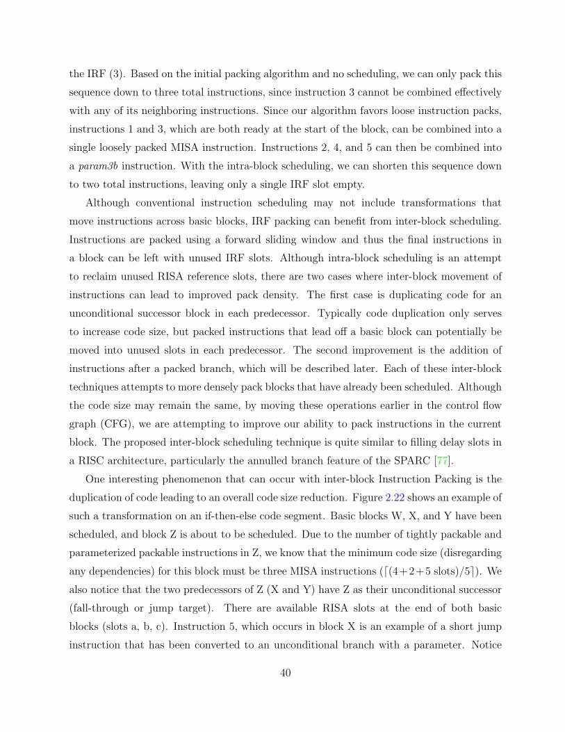
the IRF (3). Based on the initial packing algorithm and no scheduling, we can only pack this
sequence down to three total instructions, since instruction 3 cannot be combined effectively
with any of its neighboring instructions. Since our algorithm favors loose instruction packs,
instructions 1 and 3, which are both ready at the start of the block, can be combined into a
single loosely packed MISA instruction. Instructions 2, 4, and 5 can then be combined into
a param3b instruction. With the intra-block scheduling, we can shorten this sequence down
to two total instructions, leaving only a single IRF slot empty.
Although conventional instruction scheduling may not include transformations that
move instructions across basic blocks, IRF packing can benefit from inter-block scheduling.
Instructions are packed using a forward sliding window and thus the final instructions in
a block can be left with unused IRF slots. Although intra-block scheduling is an attempt
to reclaim unused RISA reference slots, there are two cases where inter-block movement of
instructions can lead to improved pack density. The first case is duplicating code for an
unconditional successor block in each predecessor. Typically code duplication only serves
to increase code size, but packed instructions that lead off a basic block can potentially be
moved into unused slots in each predecessor. The second improvement is the addition of
instructions after a packed branch, which will be described later. Each of these inter-block
techniques attempts to more densely pack blocks that have already been scheduled. Although
the code size may remain the same, by moving these operations earlier in the control flow
graph (CFG), we are attempting to improve our ability to pack instructions in the current
block. The proposed inter-block scheduling technique is quite similar to filling delay slots in
a RISC architecture, particularly the annulled branch feature of the SPARC [77].
One interesting phenomenon that can occur with inter-block Instruction Packing is the
duplication of code leading to an overall code size reduction. Figure 2.22 shows an example of
such a transformation on an if-then-else code segment. Basic blocks W, X, and Y have been
scheduled, and block Z is about to be scheduled. Due to the number of tightly packable and
parameterized packable instructions in Z, we know that the minimum code size (disregarding
any dependencies) for this block must be three MISA instructions (d(4+2+5 slots)/5e). We
also notice that the two predecessors of Z (X and Y) have Z as their unconditional successor
(fall-through or jump target). There are available RISA slots at the end of both basic
blocks (slots a, b, c). Instruction 5, which occurs in block X is an example of a short jump
instruction that has been converted to an unconditional branch with a parameter. Notice
40

...W
...W
������������������������
������������������������
����������������
����������������
������������
����������������
������������
����������������
������������
����������������
��������������������
������������������������
1
4 4’
3 3’
2
Z
������������������
������������������
������������
������������
������������
������������
������������
������������
������������
������������
2 3’ 4’3 4Z
������������������
������������������
������������������
������������������
������������
������������
������������
������������
������������������
������������������
5’51X
������������������������
������������������������
������������������������
������������������������
������������
������������
������������
������������
5 5’X
a
������������������������������������������������������������������������������������
������������������������������������������������������������������������������������
����������������
����������������
������������
������������
������������������������
������������������������
������������������
������������������
Y
b c��������������������������������������������������������������������������������
��������������������������������������������������������������������������������
������������
������������
������������
������������
������������������
������������������
������������������
������������������
������������������
������������������
1
Y
c
A) Before Inter−block Scheduling Z B) After Duplication and Scheduling Z
Figure 2.22: Duplicating Code to Reduce Code Size
that for block X, the available slots are calculated without regard for the jump instruction, as
the duplicated instruction will have to be placed before the jump in any case. Figure 2.22B
shows instruction 1 after it has been duplicated in both predecessors of Z. It is able to
be combined in two separate tight packs. Block X shows that the moved instruction is
actually placed before the jump in order to maintain correctness. After performing intra-
block scheduling on block Z, the parameterized instruction 4 is packed with instructions 2
and 3. This ultimately results in a net code size reduction of one instruction. If more than
one slot was initially available in block X, we would also be able to move instruction 2 up,
but this would not yield any additional code size reduction.
The baseline MIPS ISA that underlies our IRF architecture does not have support for
predicated execution of instructions. With compiler transformations, however, we can mimic
predication by packing instructions after conditional branches. If a forward conditional
branch is taken, then the following instructions within the pack will be skipped. If it is
not taken, then they will be executed normally, just as the fall-through block normally
41
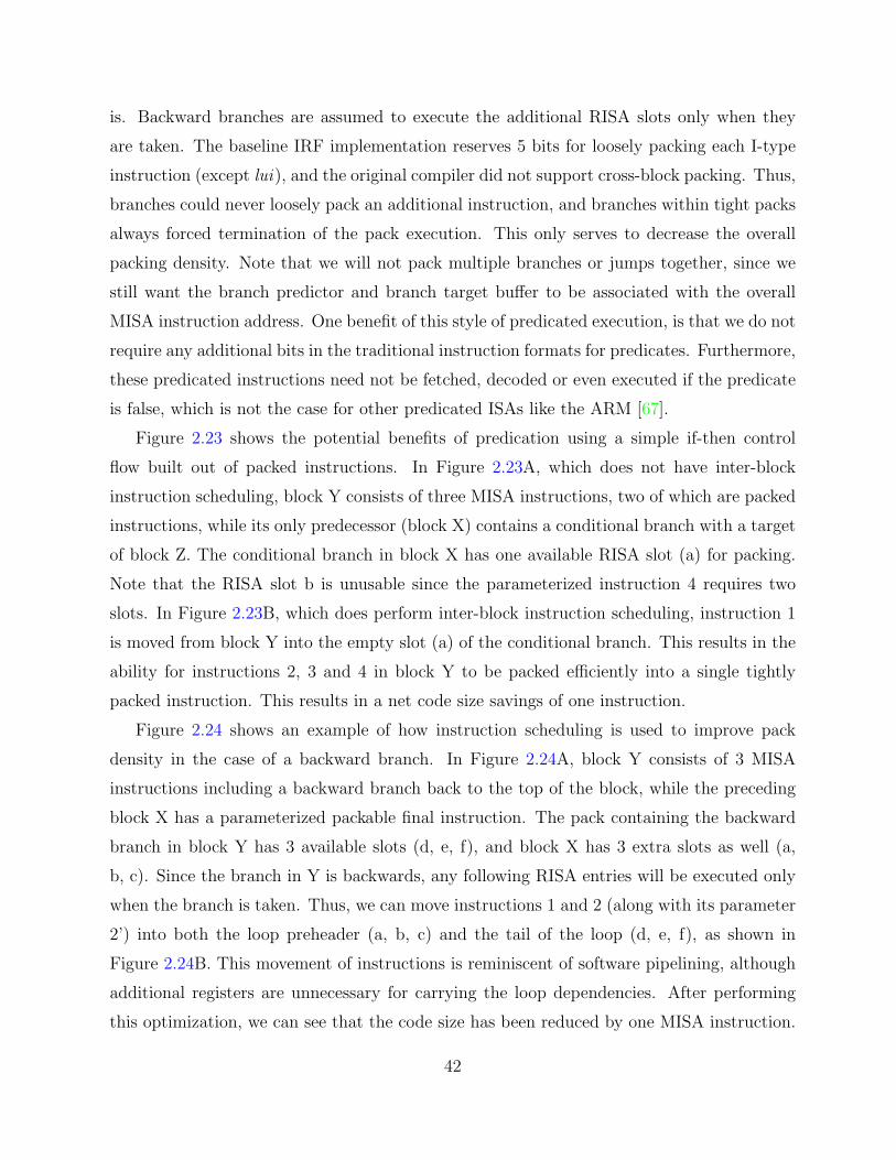
is. Backward branches are assumed to execute the additional RISA slots only when they
are taken. The baseline IRF implementation reserves 5 bits for loosely packing each I-type
instruction (except lui), and the original compiler did not support cross-block packing. Thus,
branches could never loosely pack an additional instruction, and branches within tight packs
always forced termination of the pack execution. This only serves to decrease the overall
packing density. Note that we will not pack multiple branches or jumps together, since we
still want the branch predictor and branch target buffer to be associated with the overall
MISA instruction address. One benefit of this style of predicated execution, is that we do not
require any additional bits in the traditional instruction formats for predicates. Furthermore,
these predicated instructions need not be fetched, decoded or even executed if the predicate
is false, which is not the case for other predicated ISAs like the ARM [67].
Figure 2.23 shows the potential benefits of predication using a simple if-then control
flow built out of packed instructions. In Figure 2.23A, which does not have inter-block
instruction scheduling, block Y consists of three MISA instructions, two of which are packed
instructions, while its only predecessor (block X) contains a conditional branch with a target
of block Z. The conditional branch in block X has one available RISA slot (a) for packing.
Note that the RISA slot b is unusable since the parameterized instruction 4 requires two
slots. In Figure 2.23B, which does perform inter-block instruction scheduling, instruction 1
is moved from block Y into the empty slot (a) of the conditional branch. This results in the
ability for instructions 2, 3 and 4 in block Y to be packed efficiently into a single tightly
packed instruction. This results in a net code size savings of one instruction.
Figure 2.24 shows an example of how instruction scheduling is used to improve pack
density in the case of a backward branch. In Figure 2.24A, block Y consists of 3 MISA
instructions including a backward branch back to the top of the block, while the preceding
block X has a parameterized packable final instruction. The pack containing the backward
branch in block Y has 3 available slots (d, e, f), and block X has 3 extra slots as well (a,
b, c). Since the branch in Y is backwards, any following RISA entries will be executed only
when the branch is taken. Thus, we can move instructions 1 and 2 (along with its parameter
2’) into both the loop preheader (a, b, c) and the tail of the loop (d, e, f), as shown in
Figure 2.24B. This movement of instructions is reminiscent of software pipelining, although
additional registers are unnecessary for carrying the loop dependencies. After performing
this optimization, we can see that the code size has been reduced by one MISA instruction.
42

taken pathBranch
taken pathBranch
...
......
...
������������������������������������������������������������
������������������������������������������������������������
������������
������������
������������
������������������������������
������������������
����������������
����������������
������������������
������������������
������������
������������
������������������������������������������������������������
������������������������������������������������������������
������������������
������������������
������������
������������
������������������
������������������
������������
������������
������������
������������
������������
������������
Cond Branch a
1 2 3
4 4’
3’b
Fall−through
Cond Branch
Fall−through
1
2 3 4 3’ 4’
A) Without Inter−block Scheduling B) With Inter−block Scheduling
Y
Z
X X
Y
Z
Figure 2.23: Predication with Packed Branches
BackwardBranch
BackwardBranch
������������
������������
������������
������������
������������
������������
������������
������������
������������
������������ ���
���������
������������
������������
������������
������������
������������
������������
������������
������������
������������
������������
������������
������������
������������
������������
������������
������������
������������
������������������
������������������
������������������
������������������
������������������
������������������
������������������
������������������
������������������
������������������
��������������������������������������������������������������������������������
�������������������������������������������������������������������������������� ��������������������
������������������������������������������������������������
��������������������������������������������������������������������������������
X
Y
...X
Y
...
B) With Inter−Block SchedulingA) Without Inter−Block Scheduling
1 2 2’
1 2 2’
1 2 2’
a b c
d e f
Figure 2.24: Scheduling with Backward Branches
The complete instruction scheduling algorithm for improving pack density is shown in
Figure 2.25. It starts by performing intra-block scheduling on the function entry block
and all loop headers. We then proceed by choosing the next block that has each of its
predecessors already scheduled. If such a block is not found, then we select the next un-
scheduled block and perform just the intra-block scheduling pass. If all predecessors of a
block have been scheduled, however, then we have an opportunity to perform inter-block
instruction scheduling to move instructions from the current block up into each predecessor.
We first check if this block has a single predecessor that ends with a conditional branch. If the
last MISA instruction in the predecessor has available RISA slots, then we attempt to choose
43

irf intra sched(entry blk)foreach blk that is a loop header do
irf intra sched(blk)
while all blocks have not been scheduled doblk = next block with all preds scheduled//Predicationif blk is fall through from branch and has no other preds then
if predecessor has empty slots after branch thenattempt to move IRF insns from blk into the slots
//Duplicationok = TRUEforeach pblk ∈ blk→preds do
if pblk is unscheduled or pblk→left 6= blkor pblk has no slots then
ok = FALSE
if ok thenslots = minimum of available slots from all predecessorsforeach pblk ∈ blk→preds do
attempt to move IRF insns from blk into the slotsirf intra sched(pblk)
irf intra sched(blk)//Backward Branch Packingif blk branches back to loop header toblk then
slots = minimum of slots from toblk preds including blkforeach pblk ∈ toblk→preds do
attempt to move IRF insns from toblk into the slotsirf intra sched(pblk)
mark blk as scheduled
Figure 2.25: Instruction Scheduling for IRF
IRF instructions for movement into the available slots. If the block has multiple predecessors,
we can attempt to do duplication. Each predecessor block needs to have already been
scheduled, have additional slots, and have the current block as their unconditional successor
or branch fall-through. At this point, IRF instructions can be moved from the current block
back into each individual predecessor block. Any predecessor that is terminated by a jump
will have the moved IRF instruction placed in front of the jump, since jumps automatically
terminate basic blocks and packs. Each predecessor that has instructions moved into it is
then re-scheduled locally in order to see if a better packing solution exists and more slots
can be freed. After all inter-block scheduling has been done, the current block is locally
scheduled. By performing the inter-block scheduling early, we are filling up slots in blocks
that have already been scheduled. This has two benefits: reducing the number of instructions
44

Figure 2.26: Total Processor Energy with Optimized Packing
to schedule in the current block, and moving deeper, dependent instructions closer to being
ready in the current block. These benefits will then allow the intra-block scheduler to do a
better job of forming dense instruction packs. If this block contains a backward branch for
a loop, then we attempt to move instructions into any additional slots after the backward
branch. To do this, we have to examine all predecessors of the loop header to calculate the
minimum number of available slots. At this point, we can move instructions from the loop
into each predecessor block and reschedule.
2.7.5 Evaluating Compiler Optimizations with IRF
Figure 2.26 shows the results of applying these enhanced optimizations in terms of total
processor energy. This is different from past work on the IRF which presents results for
reducing only the fetch energy consumed by the processor. Power estimation is performed
using version 1.02 of the Wattch extensions [9] for SimpleScalar. Wattch uses Cacti [79]
to model the energy and timing requirements of various pipeline components. Energy
estimates are based on Wattch’s aggressive clock-gating model (cc3 ). Under this scheme,
power consumption scales linearly for active units, while inactive portions of the pipeline
dissipate only 10% of their maximum power. The baseline IRF architecture with no
optimizations and dynamic profiling reduces total energy to 87.8% on average. Incorporating
45

Figure 2.27: Static Code Size with Optimized Packing
the enhanced mixed instruction promotion increases the total energy consumption to 87.99%,
since we have traded some of our less important dynamic IRF entries for the ability to
capture highly redundant static code. Instruction selection boosts the total energy efficiency,
dropping the overall average to 84.35%. The re-assignment of registers increases the total
energy to 84.71%, since it is focused primarily on improving static code size. Intra-block
instruction scheduling is able to reduce the total energy to an average of 84.55%. Allowing for
inter-block instruction scheduling further reduces the fetch energy consumption to 84.18%.
Overall, instruction selection is the optimization that has the greatest impact on total energy
reduction.
Figure 2.27 shows the resulting relative static code size of an application based on the
application of these modified optimizations. The code generated for a non-IRF implemen-
tation of the ISA corresponds to 100%. The first bar shows the static code size for applying
our IRF selection process to each application using only the 4-window IRF with immediate
parameterization capabilities. The IRF with no optimizations is only able to reduce the
code size to 83.20% on average, while supporting the enhanced mixed promotion drops the
code size to 77.95%. After applying our instruction selection and register parameterization
optimizations, the average code size is reduced to 72.76%. Applying register re-assignment
reduces the code size to 72.39% of the original code size. Intra-block scheduling further
46

Figure 2.28: Execution Time with Optimized Packing
reduces code size to 71.33%, while the addition of inter-block scheduling drops it to an average
of 71.17%. These results are consistent with our intuition that the largest optimization
benefits for code size would occur due to instruction selection and intra-block scheduling,
however using a mixed dynamic and static profile also has a significant impact on code size.
The results regarding execution efficiency of the enhanced IRF optimizations are shown
in Figure 2.28. The baseline IRF is able to reduce the execution time to 98.92% on average
with dynamic profiling, and 98.91% for the enhanced mixed promotion. Adding instruction
selection slightly increases the execution time to 99.04% Register re-assignment reduces the
execution time to 98.98%, while intra-block instruction scheduling gets the overall execution
time down to 98.90% on average. Inter-block instruction scheduling decreases the execution
time to 98.7%. Fluctuations in execution time and/or IPC are primarily due to branch
misprediction, which must now account for restarting in the middle of a packed instruction
(e.g. predication). Improved profiling for commonly predicated instructions could help
to make better decisions about which instructions should be moved across basic blocks.
Additionally, instruction scheduling can sometimes move dependent instructions closer to
their original dependence, leading to potential pipeline stalls. Several of the worse performing
benchmarks are dominated by library calls. Packing these library functions specifically for
these applications could lead to significant improvements in execution efficiency.
47

Figure 2.29: Evaluating Enhanced Promotion to the IRF
Figure 2.29 is a sensitivity study on the impact of combining static and dynamic
profile information in various ways. Only code size and total energy are shown since the
execution time benefits are similar to the previous experiments. Each combination of static
and dynamic profile data is tested both with and without all of the previously described
optimizations, although promotion enhancements are enabled for all experiments. As was
expected, the static profile data yields the greatest code compression, while dynamic profile
data yields the greatest total energy savings. It is interesting that almost all of the energy
benefits (83.84% for optimized 100/0 and 84.18% for optimized 50/50) of promoting only
the most frequent dynamic instructions can still be obtained while incorporating additional
frequent static instructions in the IRF. In this case, the static code size can also be reduced
from 74.05% for optimized 100/0 to 71.17% for optimized 50/50. This is reasonably close
to the 69.33% relative code size that can be obtained from packing based on a purely static
profile. The significance of the results of this experiment is that an embedded developer
can adjust the balance of static and dynamic measures to meet varying design constraints
regarding code size and energy consumption.
48

Table 2.4: Experimental Configurations
Parameter Value
I-Fetch Queue 4 entriesBranch Predictor Bimodal – 128Branch Penalty 3 cyclesFetch/Decode/Issue/Commit 1Issue Style Out-of-orderRUU size 8 entriesLSQ size 8 entries
16 KBL1 Data Cache 256 lines, 16 B line, 4-way assoc.
1 cycle hit16 KB
L1 Instruction Cache 256 lines, 16 B line, 4-way assoc.1 cycle hit
Instruction/Data TLB 32 entries, Fully assoc., 1 cycle hitMemory Latency 32 cyclesInteger ALUs 1Integer MUL/DIV 1Memory Ports 1FP ALUs 1FP MUL/DIV 1
4 windows32-entry IRF (128 total)IRF/IMM32-entry Immediate Table
1 Branch/pack
2.8 Experimental Evaluation of IRF
This section presents experimental results for each of the enhancement categories that we
have applied to Instruction Packing with an IRF. These results represent our most recent
complete simulations of a 4-window Instruction Register File with parameterization, mixed
profiling and each of the adapted compiler optimizations. The baseline architecture of the
processor is described completely in Table 2.4. It is a single issue, out-of-order execution
engine with separate 8KB, 4-way set-associative L1 instruction and data caches, and a 128-
entry bimodal branch predictor. Results are presented as percentage of the relevant metric
compared to the baseline processor values, whether it is total processor energy, static code
size, or execution cycles. Lower values are better in all cases (reduced energy consumption,
reduced code size, and reduced execution time).
Figure 2.30 shows the savings in energy consumption due to the addition of an Instruction
Register File and its associated enhancements. A simple baseline IRF provides a total savings
49

Figure 2.30: Processor Energy Consumption with an IRF
of 9.28% of the total processor energy consumption, while adding parameterization boosts
the savings to 10.42%. Windowing brings the savings up to 12.10%, while mixed profiling
penalizes energy for improved code size reduction, resulting in only a 12.03% improvement.
Finally, compiler optimizations that have been tuned for Instruction Packing result in an
overall 15.82% total processor energy reduction.
Both Qsort and Basicmath experienced slight energy increases for some of the simpler
configurations (1.46% increase maximum) due to their heavy reliance on library code that
is not packed. The best performing benchmark was Susan, which was able to cut the
total processor energy consumption to 71.21% of the baseline energy. Nine of the twenty
benchmarks were able to reduce the total processor energy consumption by 20% or more.
The reduction in static code size for adding an IRF along with all enhancements is shown
in Figure 2.31. The standard 32-entry IRF yields a code size savings of 10.29%, while adding
support for parameterization with a 32-entry IMM increases savings to 11.39%. Hardware
50
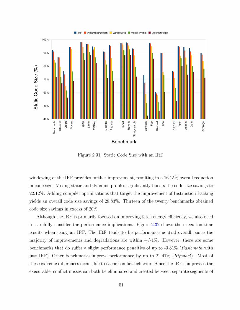
Figure 2.31: Static Code Size with an IRF
windowing of the IRF provides further improvement, resulting in a 16.15% overall reduction
in code size. Mixing static and dynamic profiles significantly boosts the code size savings to
22.12%. Adding compiler optimizations that target the improvement of Instruction Packing
yields an overall code size savings of 28.83%. Thirteen of the twenty benchmarks obtained
code size savings in excess of 20%.
Although the IRF is primarily focused on improving fetch energy efficiency, we also need
to carefully consider the performance implications. Figure 2.32 shows the execution time
results when using an IRF. The IRF tends to be performance neutral overall, since the
majority of improvements and degradations are within +/-1%. However, there are some
benchmarks that do suffer a slight performance penalties of up to -3.81% (Basicmath with
just IRF). Other benchmarks improve performance by up to 22.41% (Rijndael). Most of
these extreme differences occur due to cache conflict behavior. Since the IRF compresses the
executable, conflict misses can both be eliminated and created between separate segments of
51

Figure 2.32: Execution Time with an IRF
the code. The IRF can have a similar effect with regards to branch prediction. It is important
to note that although execution times may increase slightly, overall energy consumption for
those benchmarks is still reduced when considering each of the possible IRF enhancements.
2.9 Integration with Additional Fetch EnergyEnhancements
2.9.1 Combining Instruction Packing with a Loop Cache
We have also found that using an IRF can be complementary, rather than competitive,
with other architectural and/or compiler approaches for reducing energy consumption and
compressing code size. One complementary technique for reducing instruction fetch energy
is a loop cache. In this section we show that the combination of using an IRF and a loop
cache reduces energy consumption much more than using either feature in isolation [31].
A loop cache is a small instruction buffer that is used to reduce instruction fetch energy
52

when executing code in small loops [26]. We modified SimpleScalar to simulate the execution
of the loop cache described by Lee, Moyer, and Arends [49]. This loop cache has three
modes: inactive, fill, and active. The hardware detects when a short backward branch (sbb)
instruction is taken whose target is within a distance where the instructions between the
target and the sbb will fit into the loop cache. At that point the loop cache goes into fill
mode, which means that the instructions are fetched from the IC and placed in the loop
cache. After encountering the sbb instruction again, the loop cache is set to active mode,
when instructions are only fetched from the loop cache. Whenever there is a taken transfer
of control that is not the sbb instruction or the sbb instruction is not taken, the loop cache
goes back to inactive mode and instructions are fetched from the IC. Thus, loop caches can
be exploited without requiring the addition of any new instructions to the ISA.
One of the limiting factors for using this style of loop cache is the number of instructions
within the loop. This factor can be mitigated to a large extent by the use of an IRF. For
each tightly packed MISA instruction, there are up to five RISA instructions that are fetched
from the IRF. The loop cache contains only the MISA instructions. Thus, the number of
total instructions executed from the loop cache can potentially increase by a factor of five.
Figure 2.33 shows the instruction fetch cost of using a loop cache, a 4 window IRF, and
a 4 window IRF with a loop cache normalized against using no IRF and no loop cache. We
varied the size of the loop cache to contain 4, 8, 16, 32, and 64 instructions. The energy
requirement of a loop cache access closely compares to that of a single IRF access. Each
of these experiments is performed using a modified SimpleScalar that measures accesses to
various types of instruction memory and the IRF. A MISA instruction fetched from the
loop cache and that contains five RISA references would have an approximate fetch cost of
0.016 since there has to be a fetch from both the loop cache and the IRF before the first
RISA instruction can be executed. We found that the loop cache and IRF can cooperate to
further reduce instruction fetch costs. Whereas an 8-entry loop cache reduces the fetch cost
to 93.26%, and a 4 window IRF can reduce fetch cost to 53.28%, the combination of such
an IRF with a loop cache reduces the instruction fetch cost to 43.84%.
The results show clearly that a loop cache and an IRF can operate in a complementary
fashion, often obtaining better results than either can separately. One limitation of a loop
cache is that the maximum loop size is fixed, and any loop that extends beyond the sbb
distance can never be matched. Packing instructions naturally shortens this distance for
53
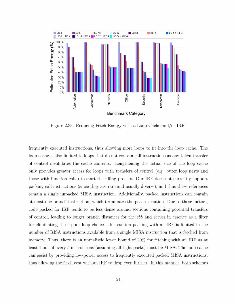
Figure 2.33: Reducing Fetch Energy with a Loop Cache and/or IRF
frequently executed instructions, thus allowing more loops to fit into the loop cache. The
loop cache is also limited to loops that do not contain call instructions as any taken transfer
of control invalidates the cache contents. Lengthening the actual size of the loop cache
only provides greater access for loops with transfers of control (e.g. outer loop nests and
those with function calls) to start the filling process. Our IRF does not currently support
packing call instructions (since they are rare and usually diverse), and thus these references
remain a single unpacked MISA instruction. Additionally, packed instructions can contain
at most one branch instruction, which terminates the pack execution. Due to these factors,
code packed for IRF tends to be less dense around sections containing potential transfers
of control, leading to longer branch distances for the sbb and serves in essence as a filter
for eliminating these poor loop choices. Instruction packing with an IRF is limited in the
number of RISA instructions available from a single MISA instruction that is fetched from
memory. Thus, there is an unrealistic lower bound of 20% for fetching with an IRF as at
least 1 out of every 5 instructions (assuming all tight packs) must be MISA. The loop cache
can assist by providing low-power access to frequently executed packed MISA instructions,
thus allowing the fetch cost with an IRF to drop even further. In this manner, both schemes
54
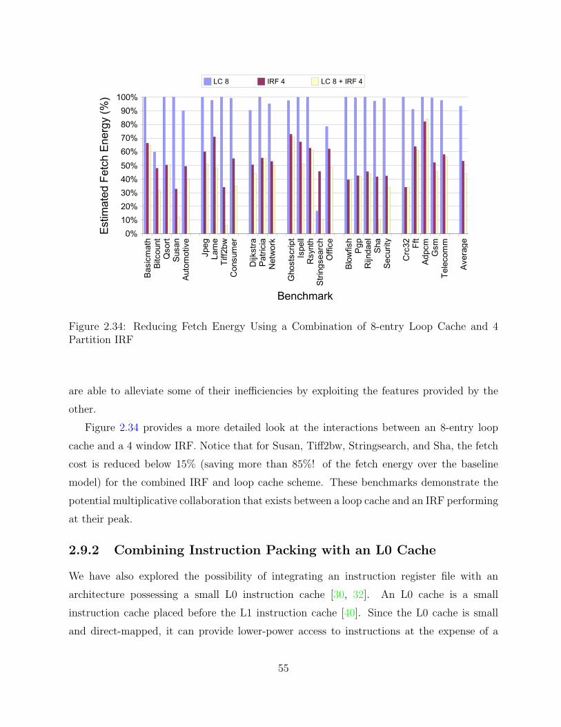
Figure 2.34: Reducing Fetch Energy Using a Combination of 8-entry Loop Cache and 4Partition IRF
are able to alleviate some of their inefficiencies by exploiting the features provided by the
other.
Figure 2.34 provides a more detailed look at the interactions between an 8-entry loop
cache and a 4 window IRF. Notice that for Susan, Tiff2bw, Stringsearch, and Sha, the fetch
cost is reduced below 15% (saving more than 85%! of the fetch energy over the baseline
model) for the combined IRF and loop cache scheme. These benchmarks demonstrate the
potential multiplicative collaboration that exists between a loop cache and an IRF performing
at their peak.
2.9.2 Combining Instruction Packing with an L0 Cache
We have also explored the possibility of integrating an instruction register file with an
architecture possessing a small L0 instruction cache [30, 32]. An L0 cache is a small
instruction cache placed before the L1 instruction cache [40]. Since the L0 cache is small
and direct-mapped, it can provide lower-power access to instructions at the expense of a
55

higher miss rate. The L0 cache also imposes an extra execution penalty for accessing the
L1 cache, as the L0 cache must be checked first to avoid the higher energy cost of accessing
the L1 cache. Previous studies have shown that the fetch energy savings of a 256-byte L0
cache with an 8-byte line size is approximately 68%, but the execution time is increased by
approximately 46% due to miss overhead [40].
Instruction Packing can be used to diminish these small cache performance penalties.
The nature of the IRF allows for an improved overlap between the execution and fetch
of instructions, since each packed instruction essentially translates into several lower-cost
fetches from the IRF. While the fetch stage of the pipeline is servicing an L0 instruction
cache miss, the processor can continue decoding and executing instructions from the IRF.
In this way, the IRF can potentially mask a portion of the additional latency due to a small
instruction cache. Although an L0 instruction cache and an IRF attempt to reduce overall
fetch energy, we show that both architectural features are orthogonal and are able to be
combined for improved fetch energy consumption as well as reduced performance penalties
due to L0 cache misses. We believe that the IRF can be similarly applied to instruction
encryption and/or code compression techniques that also affect the instruction fetch rate, in
an effort to reduce the associated performance penalties.
There are several intuitive ways in which an IRF and an L0 instruction cache can interact
effectively. First, the overlapped fetch of packed instructions can help in alleviating the
performance penalties of L0 instruction cache misses by giving the later pipeline stages
meaningful work to do while servicing the miss. Second, the very nature of Instruction
Packing focuses on the frequent access of instructions via the IRF, leading to an overall
reduction in the number of instruction cache accesses. Third, the packing of instructions
reduces the static code size of portions of the working set of an application, leading to
potentially fewer overall instruction cache misses.
Figure 2.35 shows the pipeline diagrams for two equivalent instruction streams. Both
diagrams use a traditional five stage pipeline model with the following stages: IF —
instruction fetch, ID — instruction decode, EX — execute, M — memory access, and WB —
writeback. In Figure 2.35(a), an L0 instruction cache is being used with no IRF. The first
two instructions (Insn1 and Insn2) execute normally with no stalls in the pipeline. The third
instruction is a miss in the L0 cache, leading to the bubble at cycle 4. The fourth instruction
is unable to start fetching until cycle 5, when Insn3 has finally finished fetching and made it
56

Figure 2.35: Overlapping Fetch with an IRF
to the decode stage of the pipeline. This entire sequence takes 9 cycles to finish executing.
Figure 2.35(b) shows the same L0 instruction cache being used with an IRF. In this
stream, however, the second and third instructions (previously Insn2 and Insn3) are packed
together into a single MISA instruction, and the fourth instruction (third MISA instruction)
is now at the address that will miss in the L0 cache. We see that the packed instruction is
fetched in cycle 2. The packed instruction decodes its first RISA reference (Pack2a) in cycle
3, while simultaneously we are able to start fetching instruction 4. The cache miss bubble
in cycle 4 is overlapped with the decode of the second RISA instruction (Pack2b). After the
cache miss is serviced, Insn4 is now ready to decode in cycle 5. In this way, sequences of
instructions with IRF references can alleviate stalls due to L0 instruction cache misses. This
stream finishes the same amount of work as the first stream in only 8 cycles, 1 less cycle than
the version without IRF. Denser sequences of instructions (with more packed instructions)
allow for even greater cache latency tolerance, and can potentially alleviate a portion of the
latency of accessing an L2 cache or main memory on an L1 instruction cache miss.
In previous studies, it was shown that approximately 55% of the non-library instructions
fetched in an application can be accessed from a single 32-entry IRF [28]. This amounts
to a significant fetch energy savings due to not having to access the L1 instruction cache
as frequently. Although the L0 cache has a much lower energy cost per access than an L1
instruction cache, the IRF will still reduce the overall traffic to the entire memory hierarchy.
57

Figure 2.36: Execution Efficiency with an L0 Instruction Cache and an IRF
Fewer accesses that reach into the memory hierarchy can be beneficial as energy can be
conserved by not accessing the ITLB or even the L0 cache tag array.
Instruction packing is inherently a code compression technique, allowing some additional
benefits to be extracted from it as well. As instructions are packed together, the L0
instruction cache can potentially handle larger working sets at no additional cost. Given
that the L0 cache is fairly small and direct-mapped, the compressed instruction stream may
be extremely beneficial in some cases, allowing for fewer L0 cache misses, which translates
into performance improvements and reduced overall fetch energy consumption.
Each of the graphs in this subsection use the following conventions. All results are
normalized to the baseline case for the particular processor model, which uses an L1
instruction cache with no L0 instruction cache or IRF. The label Baseline+IRF corresponds
to adding an IRF but no L0 cache. The label L0 corresponds to adding an L0 instruction
cache, but no IRF. Finally, L0+IRF corresponds to the addition of an L0 instruction cache
along with an IRF. With 2cycle, we are representing a 2-cycle non-pipelinable L1 instruction
cache, while 2cycle+IRF represents this configuration with an IRF. Execution results are
presented as normalized instructions per cycle (IPC) as measured by SimpleScalar. Energy
results are based on the overall total processor energy consumption.
58
Figure 2.36 shows the execution efficiency of various combinations of an L0 or 2 cycle
instruction cache and an IRF. Adding an IRF to the baseline processor actually yields a net
IPC improvement of 1.04%, primarily due to the code fitting better into the L1 instruction
cache. An L0 cache degrades the IPC by 12.89% on average, while adding an IRF cuts this
penalty to 6.14%. The 6.75% improvement from adding the IRF to an L0 cache configuration
is greater than the original IPC improvement provided by adding the IRF to the baseline
processor. These benefits are due to the smaller cache footprint provided by instruction
packing, as well as the overlap of fetch stalls with useful RISA instructions. The Rijndael
and Gsm benchmarks are even able to surpass the baseline performance with no L0 cache,
yielding IPCs of 126.11% and 102.13% respectively. The 2 cycle implementation reduces IPC
to 49.73% of its original value, while adding an IRF increases IPC to 78.28%, nearly a 57%
improvement. Several of the automotive category benchmarks still experience diminished
performance when adding an IRF, due to their dependence on library routines which are not
packed. However, it is clear that the IRF can be used to mask some of the performance issues
involved in complex fetch configurations that utilize low-power components, compression or
even encryption.
The energy efficiency of the varied IRF, L0 and 2 cycle instruction cache configurations
are shown in Figure 2.37. Adding an IRF to the baseline processor yields an average energy
reduction of 15.66%. The L0 cache obtains an overall reduction of 18.52%, while adding the
IRF improves the energy reduction to 25.65%. The additional energy savings in the final
case is due to two factors. First, fetching instructions via the IRF requires less energy than
fetching from the L0 instruction cache, and second, the ability of the IRF to tolerate L0
cache misses improves the overall execution time of the application. When dealing with the
2 cycle instruction cache, the overall energy is increased by 17.63%. It is important to note
that the Wattch model places a heavy emphasis on the clock gating of unused pipeline units,
hence the reason for the energy consumption only increasing by 5-25% for the extended
running times. Adding an IRF to this configuration, however, reduces the overall energy
consumption to 88.19% of the baseline, which is only slightly higher than the configuration
of a 1-cycle L1 instruction cache with IRF.
The fetch energy characteristics of the IRF and L0 instruction cache are also very
interesting. The baseline processor fetch energy consumption can be reduced by 33.57%
with the introduction of an IRF. An L0 instruction cache instead reduces the fetch energy
59

Figure 2.37: Energy Efficiency with an L0 Instruction Cache and an IRF
consumption by 60.61%, while adding both yields an overall fetch energy reduction of 70.71%.
This savings can be extremely beneficial for embedded systems that have a significant portion
of their total processor energy expended during instruction fetch.
2.10 Asymmetric Pipeline Bandwidth
We have also explored IRF and Instruction Packing as techniques for enhancing the fetch of
instructions in out-of-order execution high-end processors [32]. Modern superscalar processor
designs often provide similar instruction bandwidth throughout the pipeline. In the ideal
case, instructions should flow readily from one stage to the next. Often the number and
types of functional units available in a given processor are designed to handle pipeline
stalls due to long latency operations. Load-store queues and additional ALUs can allow
further instructions to continue flowing through the pipeline without being stalled. Although
computer architects can vary the number and size of these functional units in a given pipeline,
the maximum number of instructions that can be fetched, decoded/dispatched, issued, and
committed are often the same.
This makes sense when considering steady state flow of instructions through the pipeline,
but can become problematic when accounting for the effects of instruction cache misses,
60

a) Single Issue Out−of−order Pipeline
b) Multiple Issue Out−of−order Pipeline
c) Asymmetric Bandwidth Out−of−order Pipeline
... ......
... ... ... ...
Dispatch
Dispatch
Dispatch Issue Execute
ExecuteIssue
ExecuteIssueIRF
Fetch
Fetch
Fetch
Figure 2.38: Decoupling Instruction Fetch in an Out-of-Order Pipeline
branch misprediction recovery, alignment issues, etc. There are points where instruction
fetch becomes the performance bottleneck for short periods of time, and in aggregate, these
can impact the overall processor performance. Constraining the fetch width to match the
rest of the pipeline imposes an artificial limitation on the design space exploration for a
new architecture, particularly for embedded processors where die area, power consumption,
execution time and packaging costs may be highly restrictive.
Figure 2.38 shows the first few pipeline stages for several out-of-order configurations. Note
that each stage can be further sub-divided as necessary (e.g. different cycle times for different
functional units). The simplest single issue out-of-order pipeline is shown in Figure 2.38a.
Figure 2.38b shows a multiple issue pipeline. As more functional units become available on
chip, heavy demands can be placed issue, dispatch and fetch. Techniques already exist for
appropriately scaling the issue queue [21], however the increasing pressure on instruction
fetch could complicate the design. Multi-ported instruction caches require more energy to
operate and need special techniques to handle the cases where instructions are fetched from
61
multiple cache lines. The ability of the IRF to regularly extract multiple instructions from
each instruction cache access makes it feasible to reduce the fetch width of the instruction
cache, instead relying on frequently executed packed instructions to provide the dispatch
stage with a sufficient stream of instructions to avoid starving a wider backend pipeline.
This pipeline configuration is shown in Figure 2.38c.
By packing multiple instruction references into a single MISA instruction, it becomes
feasible to decouple the configuration of the fetch pipeline from the design choices of
the rest of the pipeline. This increase in the configuration space provides the processor
designer greater flexibility in meeting multiple and often divergent, design goals. Use of
an IRF in an out-of-order pipeline can also have other positive benefits. The possibility of
misspeculation due to overaggressive fetching will be reduced. This occurs because the IRF-
resident instructions are those that are most frequently executed, and thus the hot spots of
execution will be full of tightly packed instruction sequences. Conversely, the areas that are
infrequently executed will tend to exhibit fewer packed instructions and naturally limit the
rate of instruction fetch.
The column labeled High-end Embedded in Table 2.5 describes the machine configuration
for our asymmetric pipeline bandwidth study. The IRF and IMM configuration remains the
same as previous experiments, while most other pipeline structures are scaled up for a higher
performance embedded processor. This study features many combinations of fetch, decode,
issue and commit widths. The decode, issue, and commit width are always equal to one
another, and are always greater than or equal to the fetch width. Fetching is always done
using a width that is a power of 2, since we do not want to artificially increase the number
of stalls due to instruction mis-alignment. Caches are only able to access a single block in
a cycle, so instruction sequences that span multiple cache lines will require several cycles to
fetch. Functional units for each of our configurations are added as necessary based on the
decode/issue/commit width. The instruction fetch queue is lengthened to 8 entries when the
processor reaches a fetch width of 4 instructions.
Each of the following graphs in this subsection use the following conventions. All results
are normalized to the baseline processor model, which has a single instruction fetch, decode,
issue and commit bandwidth. This is the leftmost bar presented in each of the graphs.
The graph is plotted linearly by instruction fetch width, followed by the execute width
(decode/issue/functional units/commit width) as a tie-breaker. Black bars are used to
62

Table 2.5: High-end Embedded Configurations
Parameter Value
I-Fetch Queue 4/8 entriesBranch Predictor Bimodal – 2048Branch Penalty 3 cyclesFetch Width 1/2/4Decode/Issue/Commit 1/2/3/4Issue Style Out-of-orderRUU size 16 entriesLSQ size 8 entries
32 KBL1 Data Cache 512 lines, 16 B line, 4-way assoc.
1 cycle hit32 KB
L1 Instruction Cache 512 lines, 16 B line, 4-way assoc.1 cycle hit256 KB
Unified L2 Cache 1024 lines, 64 B line, 4-way assoc.6 cycle hit
Instruction/Data TLB 32 entries, Fully assoc., 1 cycle hitMemory Latency 32 cyclesInteger ALUs 1/2/3/4Integer MUL/DIV 1Memory Ports 1/2FP ALUs 1/2/3/4FP MUL/DIV 1
4 windows32-entry IRF (128 total)IRF/IMM32-entry Immediate Table
1 Branch/pack
denote configurations that do not have an IRF, while gray bars indicate the presence of
an IRF.
Figure 2.39 shows the normalized IPC over all benchmarks for the various configurations
of the fetch and execution engine. The configurations without an IRF are often able to make
some use of the additional functional unit bandwidth (1/1 to 1/2, 2/2 to 2/3), however
they plateau quickly and are unable to use any additional available bandwidth (1/2 through
1/4, 2/3 to 2/4). The IRF versions, alternately, are able to improve steadily compared to
the previous IRF configuration, except in the 1/4+IRF case. This configuration is overly
aggressive, as the IRF is unable to supply 4 instructions per cycle for execution. Branches and
other parameterized RISA instructions occupy two slots in the packed instruction format,
thus limiting the maximum number of instructions fetchable via a single MISA instruction.
63

Figure 2.39: Execution Efficiency for Asymmetric Pipeline Bandwidth
Additionally, the IRF selection heuristic is a greedy one, and we will never be able to
produce all tightly packed instructions with 4–5 slots completely full. This limits even
the IRF’s ability to supply instructions to this overly aggressive backend, but additional
fetch bandwidth more than makes up for this limitation in more complex configurations
(2/3+IRF, 2/4+IRF). Overall however, the IRF configurations have an average IPC that is
15.82% greater than corresponding configurations without an IRF.
The energy efficiency of the various configurations of asymmetric pipeline bandwidth
are shown in Figure 2.40. Results are presented as normalized energy to the 1/1 baseline
processor configuration. Note that the Wattch model places a heavy emphasis on the clock
gating of unused pipeline units. Since the running time of the more complex configurations
is lower, the total energy is correspondingly reduced as compared to the baseline processor.
The results show that increasing the execution width by one additional instruction can yield
more efficient energy usage (1/1 to 1/2, 1/1+IRF to 1/2+IRF, 2/2+IRF to 2/3+IRF), but
greater increases in all other cases are not beneficial. Overall though, the energy results show
that IRF configurations can be as much as 22% more energy efficient (1/3+IRF, 1/4+IRF)
than corresponding configurations without an IRF. On average, the IRF configurations utilize
12.67% less energy than corresponding non-IRF configurations.
64

Figure 2.40: Energy Efficiency for Asymmetric Pipeline Bandwidth
Figure 2.41 shows the energy-delay squared (ED2) for the various asymmetric fetch
and execution bandwidth configurations. Energy-delay squared is an important metric for
exploring the processor design space. As expected, this graph is similar to the IPC results
shown in Figure 2.39, as the configurations without an IRF continue to have problems with
keeping the additional functional units of the pipeline busy (1/2 through 1/4, 2/3 to 2/4).
The IRF configurations see a small increase (1.64%) in ED2, when moving from a 1/3+IRF to
1/4+IRF, primarily due to the increased energy requirements of this configuration. Without
this data point, however, the IRF configurations smoothly scale for the varied combinations
of fetch and execute bandwidth available in the processor pipeline. On average, the relative
decrease in ED2 for using the IRF configurations over the non-IRF versions is 25.21%. In
addition, by decoupling instruction fetch and instruction execution, a computer architect
has greater freedom to explore an increased number of processor configurations with a wider
variety of energy/execution characteristics.
2.11 Crosscutting Issues
Using an IRF and IMM that is unique to each process means that more state must be
preserved at context switches. A conventional context switch simply saves state to memory
65

Figure 2.41: Energy-Delay2 for Asymmetric Pipeline Bandwidth
at the point the switch occurs, and restores this state when the process resumes. One
approach to reducing this overhead is to save a pointer to a routine associated with each
process, where the routine will reload the IRF when a process resumes. Thus, the IRF would
not need to be saved, only restored.
A related issue is how to address exceptions that occur during execution of a packed
instruction when structural or data hazards prevent all of the instructions from being
simultaneously issued. One or more RISA instructions referenced by the packed instruction
have already completed at the point the exception occurs. One solution is to store in the
context state how many RISA instructions within the packed instruction have completed,
since these instructions are executed in order. A bitmask of retired instructions would allow
for a precise restart after handling the exception in an out-of-order machine. The addition
of a bitmask would not add much overhead to the system.
2.12 Concluding Remarks
We have shown that instruction fetch efficiency can be improved by the addition of a small
Instruction Register File (IRF) that contains the most frequently executed instructions.
Fetch energy is reduced since some instructions can be accessed via low-power instruction
66

registers instead of the L1 instruction cache. Code size is reduced due to the ability of
multiple IRF references to be packed together in a single instruction fetched from memory.
Code compression can be very important for embedded architectures, which are often more
tightly constrained than general purpose processors. Even execution time can be slightly
improved through the use of an IRF, since applications may now fit better into cache,
and can recover from branch mispredictions faster. L1 miss penalties may also be slightly
mitigated due to the overlapped execution property that IRF provides.
Instruction packing with an IRF has also been shown to be complementary with a variety
of other fetch energy enhancements including filter caches and loop caches. The use of an
IRF with a high-performance out-of-order embedded processor system gives the architect the
ability to scale back the fetch width in order to meet tighter power constraints, while relying
on frequently packed instructions to feed a more aggressive pipeline backend. This provides
greater flexibility in the overall pipeline design, enabling the architect to meet increasingly
demanding and potentially conflicting design goals.
67
CHAPTER 3
Guaranteeing Instruction Fetch Behavior
This chapter presents two enhancements that focus on capturing and exploiting the regularity
inherent in instruction fetch. First, we present the Tagless Hit Instruction Cache (TH-IC),
which is a small cache design that reduces fetch energy by eliminating tag comparisons
on guaranteed hits [34]. The TH-IC is able to be bypassed on potential misses, thus
avoiding the additional miss penalty normally associated with small filter caches. Next,
we discuss the Lookahead Instruction Fetch Engine (LIFE), which extends TH-IC to be able
to selectively disable the speculation components in instruction fetch [29]. We also explore
how the instruction fetch behavior captured by LIFE can be used to improve other pipeline
decisions through a case study involving next sequential line prefetch.
3.1 Motivation – Instruction Fetch Regularity
Although traditional caches are often found on embedded processors, many also include
specialized cache structures to further reduce energy requirements. Such structures include
filter caches [40, 41], loop caches [49], L-caches [5, 6], and zero-overhead loop buffers
(ZOLBs) [20]. Techniques like drowsy caching [39] can also be applied to further reduce
power consumption.
Filter or L0 instruction caches (L0-IC) are small, and typically direct-mapped caches
placed before the L1 instruction cache (L1-IC) for the purpose of providing more energy-
efficient access to frequently fetched instructions [40, 41]. Since the L0-IC is accessed instead
of the L1-IC, any miss in the L0-IC incurs an additional 1-cycle miss penalty prior to
fetching the appropriate line from the L1-IC. Figure 3.1a shows the traditional layout of
a small L0/filter IC. Although an L0-IC reduces the requirements for fetch energy, these
miss penalties can accumulate and result in significant performance degradation for some
68

Figure 3.1: Traditional L0/Filter and Tagless Hit Instruction Cache Layouts
applications. It is important to note that this performance loss will indeed reduce some of
the energy benefit gained by adding the L0-IC due to having to actively run the processor for
a longer period of time. The inclusion of an L0-IC in a memory system design is essentially
a tradeoff providing a savings in fetch energy at the expense of longer execution times.
In this chapter, we propose an alternative configuration for a small instruction cache to be
used in conjunction with an L1-IC. This configuration is shown in Figure 3.1b and is related
to previous research that has sought to bypass the small cache based on predictions [74]. We
have renamed the small IC as a Tagless Hit Instruction Cache or TH-IC. Using just a few
specialized metadata bits, the TH-IC supplies a fetched instruction only when the instruction
is guaranteed to reside in it. As a side effect of the way in which guarantees are implemented,
we no longer require tag comparisons on hits, hence the term “Tagless Hit”. The small size
of the cache and its novel use of metadata is what facilitates the ability to make guarantees
about future cache hits, while still retaining the ability to operate and update in an energy-
and performance-conscious manner. A TH-IC of similar size to an L0-IC has nearly the
same hit rate and does not suffer a miss penalty since the TH-IC is not used to fetch an
instruction when a miss may occur. In essence, the TH-IC acts as a filter cache for those
instructions that can be determined to be hits in the TH-IC, while all instructions that
69
cannot be guaranteed to reside in the TH-IC access the L1-IC without delay. Additionally,
the energy savings is greater than using a L0-IC due to the faster execution time (the TH-IC
has no miss penalty), the reduction in ITLB accesses (the TH-IC can be accessed using bits
from the portion of the virtual address that is unaffected by the translation to a physical
address), as well as the elimination of tag comparisons on cache hits (since we do not need
to check a tag to verify a hit). TH-IC exploits the regularity of instruction fetch to provide
energy-efficient access to those instructions encountered most frequently (sequential fetches
of instructions within tight loops).
While TH-IC focuses on reducing the instruction cache power, there are other components
of instruction fetch that can also have a sizable impact on the processor power characteristics.
In particular, speculation logic can account for a significant percentage of fetch power
consumption even for the limited speculation performed in scalar embedded processors.
With advances in low-power instruction cache design, these other fetch components can
even begin to dominate instruction fetch power requirements. The Lookahead Instruction
Fetch Engine (LIFE) is a new approach for instruction fetch that attempts to reduce access to
these power-critical structures when it can be determined that such an access is unnecessary.
LIFE exploits knowledge available in the TH-IC about the next instruction to be fetched
to selectively bypass speculation mechanisms present in the fetch pipeline stage. If the next
sequential instruction can be guaranteed to not be a transfer of control instruction, then the
branch predictor (BP), branch target buffer (BTB), and return address stack (RAS) do not
need to be activated during its fetch. Thus LIFE improves utilization of fetch-associated
structures by selectively disabling access. This results in reductions in both fetch power and
energy consumption, while not increasing execution time. The reduction in power is affected
by the hit rate of the TH-IC and the ratio of branch and non-branch instructions in the TH-
IC. LIFE can further capitalize on common instruction fetch behavior by detecting transfers
of control that will be predicted as not-taken, which allows bypass of the BTB and RAS
on subsequent fetches since they act as non-branch instruction flow. A substantial number
of branches resolve as not-taken and are consistent for the entire execution. Identifying
those branches residing in the TH-IC that are almost always not-taken enables the branch
predictor to also be bypassed.
Figure 3.2 shows the organization of LIFE, which extends the capabilities of TH-IC with
additional metadata for tracking the branching behavior of instructions. Bold dashed lines
70

select nextaddress
Instruction
Fetch Address BTB RAS ITLB L1 IC
LIFEinf
TH IC
PCincr
BP
Figure 3.2: LIFE Organization
represent control of fetch components by LIFE. Depending on the available metadata, LIFE
can choose to enable or disable access to appropriate fetch structures during the following
instruction fetch cycle.
In addition to directing access of fetch structures, the behaviors detected by LIFE can
also be used to guide decisions that are made in subsequent pipeline stages. Traditional next
sequential line prefetching schemes often trade off energy efficiency for improved performance
from the data cache [25, 70, 72]. Although the previously published TH-IC approach is not
suitable for data caches due to the lack of identifiable access regularity, the instruction
behavior of an application can yield clues about data access patterns. This behavioral
information can then be used to improve next sequential line prefetching.
3.2 Tagless Hit Instruction Cache (TH-IC)
This section presents an overview of the design of the Tagless Hit instruction cache (TH-
IC). First, we describe the intuition behind removing tag comparisons from our small IC, as
well as the principles involved in guaranteeing when the next instruction fetch will be a hit.
Second, we explore the new IC metadata and the rules required for guaranteeing tagless hits.
Finally, we propose four invalidation policies for efficiently managing the cache metadata.
3.2.1 Guaranteeing Tagless Hits
One of the key principles in the design of the TH-IC is the idea of bypassing the TH-IC
when we are not certain that the requested instruction/line is resident in the TH-IC. This
leaves three possibilities when an instruction is fetched: 1) it is guaranteed to be a hit in the
TH-IC, 2) it resides in the TH-IC, but we were not sure so we directly accessed the L1-IC, or
71
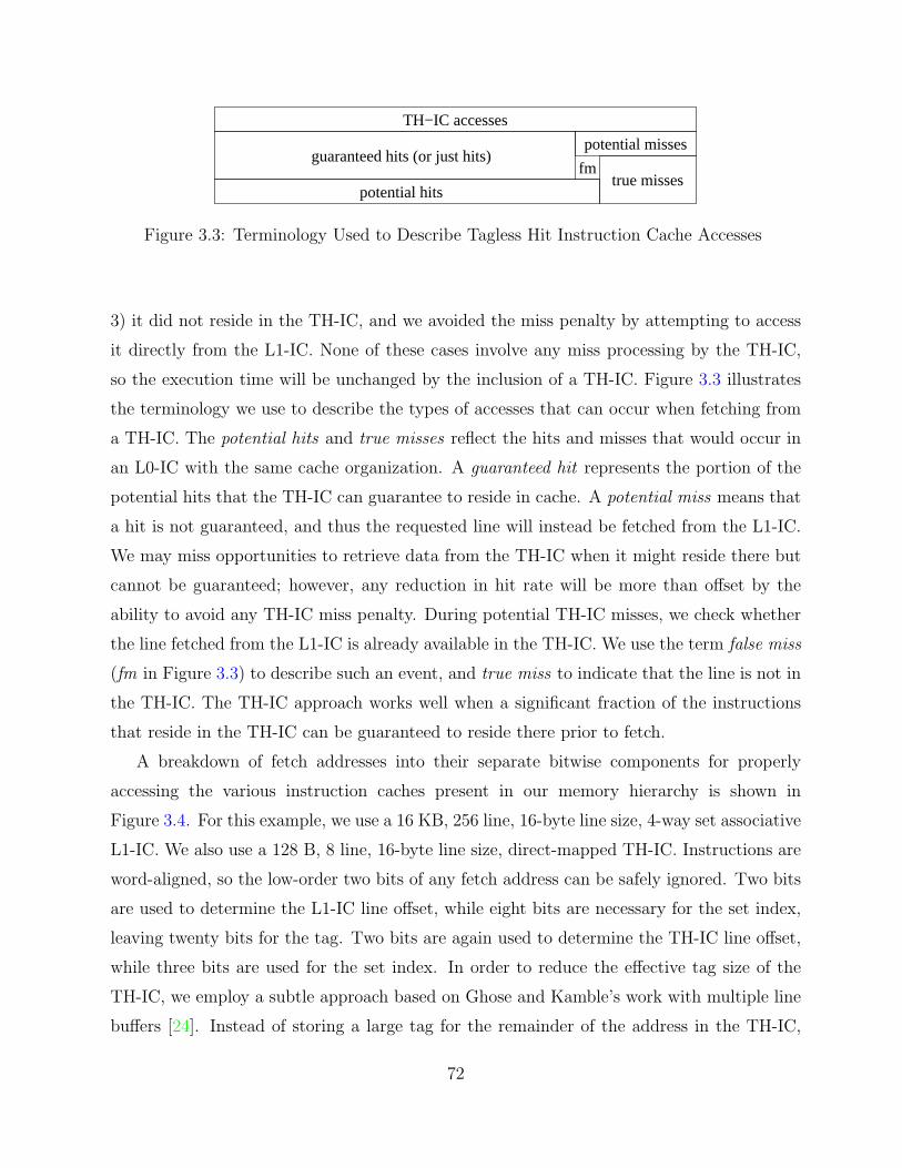
fmtrue misses
potential missesguaranteed hits (or just hits)
potential hits
TH−IC accesses
Figure 3.3: Terminology Used to Describe Tagless Hit Instruction Cache Accesses
3) it did not reside in the TH-IC, and we avoided the miss penalty by attempting to access
it directly from the L1-IC. None of these cases involve any miss processing by the TH-IC,
so the execution time will be unchanged by the inclusion of a TH-IC. Figure 3.3 illustrates
the terminology we use to describe the types of accesses that can occur when fetching from
a TH-IC. The potential hits and true misses reflect the hits and misses that would occur in
an L0-IC with the same cache organization. A guaranteed hit represents the portion of the
potential hits that the TH-IC can guarantee to reside in cache. A potential miss means that
a hit is not guaranteed, and thus the requested line will instead be fetched from the L1-IC.
We may miss opportunities to retrieve data from the TH-IC when it might reside there but
cannot be guaranteed; however, any reduction in hit rate will be more than offset by the
ability to avoid any TH-IC miss penalty. During potential TH-IC misses, we check whether
the line fetched from the L1-IC is already available in the TH-IC. We use the term false miss
(fm in Figure 3.3) to describe such an event, and true miss to indicate that the line is not in
the TH-IC. The TH-IC approach works well when a significant fraction of the instructions
that reside in the TH-IC can be guaranteed to reside there prior to fetch.
A breakdown of fetch addresses into their separate bitwise components for properly
accessing the various instruction caches present in our memory hierarchy is shown in
Figure 3.4. For this example, we use a 16 KB, 256 line, 16-byte line size, 4-way set associative
L1-IC. We also use a 128 B, 8 line, 16-byte line size, direct-mapped TH-IC. Instructions are
word-aligned, so the low-order two bits of any fetch address can be safely ignored. Two bits
are used to determine the L1-IC line offset, while eight bits are necessary for the set index,
leaving twenty bits for the tag. Two bits are again used to determine the TH-IC line offset,
while three bits are used for the set index. In order to reduce the effective tag size of the
TH-IC, we employ a subtle approach based on Ghose and Kamble’s work with multiple line
buffers [24]. Instead of storing a large tag for the remainder of the address in the TH-IC,
72

Figure 3.4: Fetch Address Breakdown
it is sufficient to identify the corresponding line in the L1-IC by storing the set index and
the location of the line in the set. Not storing the entire tag in the TH-IC is possible since
the L1-IC is being accessed simultaneously and a true miss will occur if the L1-IC misses.
The cache inclusion principle guarantees that any line in the TH-IC must also reside in the
L1-IC. Thus by detecting an L1-IC hit and verifying the precise L1-IC line that corresponds
to our TH-IC line, we can effectively determine whether we have a false miss.
The figure shows that we construct a TH-IC ID field that is made up of the additional
high-order bits from the L1-IC set index along with two bits for specifying which line in the
cache set is actually associated with this particular line address (it’s “way”). When we are
updating the TH-IC (on a potential miss), we are already accessing the L1-IC, so we only
need to compare whether we have the appropriate set/way from the L1-IC already in the
TH-IC. The miss check can be done by concatenating the two-bit way information for the
currently accessed line in the L1-IC and the five high-order bits of the address corresponding
73

to the L1-IC set index, and comparing this result to the stored TH-IC ID of the given set.
If these seven bits match, then the TH-IC currently contains the same line from the L1-IC
and we indeed have a false miss. If these bits do not match, or the L1-IC cache access is also
a miss, then we have a TH-IC true miss and must update the line data as well as the TH-IC
ID with the appropriate way and high index information. The ID field can be viewed as a
line pointer into the L1-IC that is made up of way information plus a small slice of what
would have otherwise been the TH-IC tag. If the L1-IC were direct-mapped, the ID field
would only consist of the extra bits that are part of the L1-IC set index but not the TH-IC
set index. The cache inclusion property thus allows us to significantly reduce the cost of a
tag/ID check even when the TH-IC cannot guarantee a “tagless” hit.
Figure 3.5 shows a more detailed view of an instruction fetch datapath that includes
a TH-IC. The TH-IC has been extended to use additional metadata bits (approximately
110 total bits for the simplest configuration we evaluated). The first aspect to notice in
the TH-IC is the presence of a single decision bit for determining where to fetch the next
instruction from (Fetch From TH-IC? ). This decision bit determines when the TH-IC will
be bypassed and is updated based on the metadata bits contained in the TH-IC line for the
current instruction being fetched, as well as the branch prediction status (predict taken or
not taken). We also keep track of the last instruction accessed from the TH-IC (using the
pointer Last Inst). The last line accessed from the TH-IC (Last Line) can easily be extracted
from the high-order bits of the last instruction pointer.
There are really two distinct types of access in the TH-IC or any other instruction cache
for that matter: sequential accesses and transfers of control. If the predictor specifies a direct
transfer of control (taken branch, call or jump), then the TH-IC will make use of the Next
Target bit (NT), one of which is associated with each instruction present in the small cache.
If the current instruction has its NT bit set, then the transfer target’s line is guaranteed to
be available and thus the next instruction should be fetched from the TH-IC. If the NT bit is
not set, then the next instruction should be fetched from the L1-IC instead, and the TH-IC
should be updated so that the previous instruction’s target is now in the TH-IC. We discuss
a variety of update policies and their associated complexity in the next subsection. In this
figure, the last instruction fetched was Insn5, which resides in line 1. The branch predictor
(which finished at the end of the last cycle’s IF) specified that this was to be a taken branch
and thus we will be fetching Insn5 ’s branch target, which is Insn2. The corresponding NT
74

Figure 3.5: Tagless Hit Instruction Cache
bit was set, so the TH-IC is going to be used to fetch the target instruction on this cycle. We
thus fetch Insn2 from line 0 of the TH-IC. Since the cache is direct-mapped, there is only
a single line where this instruction can reside. Note that the tag/ID check is unnecessary,
since the NT bit guarantees that this instruction’s branch target is currently available in the
TH-IC.
On a sequential fetch access (branch prediction is not taken), there are two possible
scenarios to consider. If we are accessing any instruction other than the last one in the line,
75

fetched
inst 1
inst 5
insts 6,7
inst 2
insts 3,4
inst 5
insts 6,7
insts 2
insts 3,4
inst 5
insts 6,7
inst 8
false miss
false miss
miss
miss
hits
hits
hits
hit
hits
hits
hit
hit
set inst 1 NT bit
result
set inst 7 NT bit
set line 1 NS bit
inst 1
inst 2
inst 3
inst 4
inst 5
inst 6
inst 7
inst 8
...
...
line
1lin
e 2
metadata set
set line 0 NS bit
Figure 3.6: TH-IC Example
then we will always choose to fetch the next instruction from the TH-IC, since we know
that the next sequential instruction in this same line will still be available on the subsequent
access. This process is similar to the operation of a sophisticated line buffer [23]. If it is the
last instruction in the line that is instead being fetched, then fetching the next instruction
from the TH-IC will occur only if the Next Sequential bit (NS) is set. This bit signifies that
the next line (modulo the number of lines) in the cache actually contains the next sequential
line in memory. This is a behavior that line buffers do not support, since they only hold a
single line at a time, and thus must always return to fetch from the L1-IC when they reach
the end of the line.
Figure 3.6 shows an example that illustrates how instructions can be guaranteed to reside
in the TH-IC. The example in the figure contains eight instructions spanning four basic blocks
and two lines within the TH-IC. Instruction 1 is fetched and is a miss. The previous line’s
NS bit within the TH-IC is set since there was a sequential transition from line 0 to line 1.
Instruction 5 is fetched after the transfer of control and it is also a miss. Instruction 1’s NT
bit is set to reflect that the target of instruction 1 resides in the TH-IC. Instructions 6 and 7
are fetched and are guaranteed to be hits since they are sequential references within the same
line. Instruction 2 is fetched and it resides in the TH-IC, but it is a false miss since it was
76

not guaranteed to hit in the TH-IC (instruction 7’s NT bit is initially false). At this point,
the NT bit for instruction 7 is set to indicate its target now is in the TH-IC. Instructions
3 and 4 are fetched and are hits due to the intra-line access. Instruction 5 is fetched and
is a false miss (line 1’s NS bit is false). Line 1’s NS bit is set at this point indicating that
the next sequential line now resides in the TH-IC. The instructions fetched in the remaining
iterations of the loop are guaranteed to be hits since the TH-IC metadata indicates that the
transitions between lines (line 1’s NS bit and instruction 7’s NT bit) will be hits. Finally,
instruction 8 is fetched and will be a hit since it is a sequential reference within the same
line.
The TH-IC exploits several nice properties of small, direct-mapped instruction caches.
First of all, the nature of a direct-mapped cache allows a given fetch address to reside in
only a single location. This facilitates the tracking of cache line contents and their associated
interdependences. In addition to the elimination of tag/ID comparisons, the ITLB access
can also be avoided on TH-IC hits. This is due to the virtual to physical address translation
not affecting the page offset portion (12-bits for 4KB page size) of a fetch address. Since the
indexing of the TH-IC is accomplished using bits from the page offset (and no tag comparison
is required on guaranteed hits), we do not actually need to verify the translation. The update
and invalidation policies of the TH-IC help to maintain these conservative principles by which
hits can be guaranteed.
One special case to consider is the possibility of indirect transfers of control. If the
current instruction to be fetched is a jr or jalr instruction (jump register or jump and link
register in the MIPS ISA), then we cannot guarantee that the branch target is in the TH-IC
since the address in the register may have been updated since the last time the instruction
was executed. We instead choose to fetch from the L1-IC directly. Recognizing an indirect
transfer of control is relatively simple and can be done by checking for only 2 instructions
in the MIPS ISA. Fortunately, indirect transfers of control occur much less frequently than
direct transfers.
3.2.2 Updating Tagless Hit Instruction Cache Metadata
There are really only two important steps in the operation for the TH-IC: fetch and update.
Figure 3.7 shows a flow diagram that graphically depicts the operation of the TH-IC. The
first step is the decision based on whether to fetch from the TH-IC or the L1-IC. Fetch is
77

similar to traditional instruction fetch on a cache hit. Update replaces the concept of the
traditional cache miss. The TH-IC performs an update whenever the instruction/line being
fetched is not guaranteed to be in cache. This does not necessarily mean that the line is not
available in the cache. Availability is checked by performing a tag/ID comparison within the
TH-IC in parallel with the L1-IC fetch. On a false miss, the TH-IC need not write the cache
line from the L1-IC, and does not need to invalidate any additional cache metadata either.
If the fetch is a true miss, however, we need to replace the appropriate line in the cache
and update/invalidate various portions of the TH-IC. First of all, the new line needs to be
written into cache from the L1-IC along with its corresponding TH-IC ID. The NS bit and
the NT bits for each instruction in this line are cleared, as we cannot guarantee that any
branch target or the next sequential line are available in cache. If we are replacing a line
that is a known branch target, we need to invalidate the NT bits on all corresponding lines
that may have transfers of control to this line. This requirement to manipulate metadata for
multiple lines is not particularly onerous since the total number of metadata bits is extremely
small. There are several possible schemes for keeping track of where these transfers originate,
and four approaches are discussed in the next subsection on invalidation policies. We use the
previous branch prediction’s direction bit to determine whether we have fetched sequentially
or taken a transfer of control. If the access was sequential, the previous line’s NS bit is set
since we are simply filling the cache with the next sequential line in memory. Note that
the only time that we can have a sequential fetch causing a cache miss will be when we are
fetching the first instruction in the new line. For transfers of control, we need to keep track
of the last instruction fetched. If we are not replacing the line containing the transfer of
control, we set the last instruction’s NT bit to signify that its branch target is now available
in the small cache.
Once the instruction is fetched, we need to update the last instruction pointer (and hence
last line pointer), as well as determine whether the next fetch will come from the TH-IC or
the L1-IC. It is also at this point that we need to determine whether the current instruction
is an indirect transfer of control. Direct transfers of control do not change targets, and this is
why the NT bit is sufficient for guaranteeing that a target is available in cache. If we detect
an indirect transfer, we need to steer the next fetch to the L1-IC, since we cannot guarantee
that an indirect branch target will be unchanged. We also invalidate the last instruction
pointer so that the next fetch will not incorrectly set the indirect transfer’s NT bit.
78

Figure 3.7: Tagless Hit IC Operation
79

We rely on the result of the current cycle’s branch prediction to determine whether the
next fetch is sequential or not. If a taken direct branch is predicted, then the corresponding
NT bit for the current instruction fetch is used to decide whether to fetch from the TH-IC
or the L1-IC. If instead it is a sequential access, then we will use the NS bit of the current
fetch line if we are at the end of the line. If we are elsewhere in the line, the next instruction
will be fetched from the TH-IC based on the line buffer principle. When we have a pipeline
flush due to a branch misprediction, we choose to fetch from the L1-IC on the next cycle
since we cannot guarantee that the TH-IC contains this potentially new address.
3.2.3 Tagless Hit Instruction Cache Invalidation Policies
Invalidation policies provide the TH-IC with the ability to efficiently update its metadata so
that it operates correctly. Without a proper invalidation scheme, the TH-IC could possibly
fetch incorrect instructions since we no longer do tag/ID comparisons for verification. In
this section, we present four invalidation policies that vary in complexity from conservative
approximations to more precise tracking of the relations between the transfers of control and
their target instructions.
Figure 3.8 shows four sample line configurations for a TH-IC, where each configuration
implements a particular policy. In each configuration, each line is composed of four
instructions (Insn), a Next Sequential bit (NS), a Next Target bit (NT) for each instruction,
a Valid bit (V), as well as an ID field. The number and size of the Transfer from bits (none,
T, TLs, or TIs) is what distinguishes each configuration.
The Oblivious case is shown in Figure 3.8a. In this configuration, there are no bits
reserved for denoting the lines that transfer control to the chosen line. Under this policy,
whenever any cache line is replaced, all NT bits in the TH-IC will be cleared. This case
clearly maintains correctness, but experiences many unnecessary clears of all the NT bits.
Figure 3.8b shows the addition of a single Transfer (T) bit to each line representing that
this line is a potential transfer of control target. This bit is set when any direct transfer of
control uses this line as a target. Whenever we have a line replacement where the T bit is
set, we need to clear all NT bits similar to the oblivious policy. The savings occur when
replacing a purely non-target line (one that is not a known target of any direct transfers of
control currently in cache), which does not necessitate the clearing of any of the other NT
bits. This allows the existing NT metadata within all the lines not being fetched to continue
80

Figure 3.8: Tagless Hit Instruction Cache Line Configurations
to remain unchanged in cache. It is important to note, however, that any replaced line will
always have at least its own NT bits cleared.
The configuration shown in Figure 3.8c adds 1 bit to each line for every line in the cache
(Line-based (TLs)). The bit corresponding to a particular line in the TL field is set when
there is a direct transfer of control to this line. When the line is replaced, all NT bits will
be cleared in lines whose corresponding bit in the TLs is set.
Finally, Figure 3.8d shows the addition of 1 bit to each line for every instruction available
in the cache (Instruction-based (TIs)). A bit corresponding to an individual instruction in
the TI field is set when the instruction transfers control to the line. The only NT bits cleared
when a line is replaced are due to the corresponding instruction-specified TIs. Of all the
schemes proposed, this one is the most aggressive and requires the greatest area overhead
(and hence increased energy consumption to operate). This scheme maintains almost perfect
information about NT transfers of control for invalidation. It is only conservative in that
81
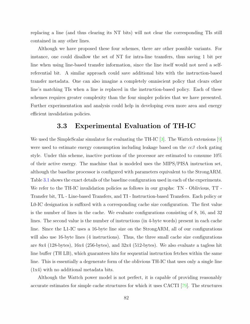
replacing a line (and thus clearing its NT bits) will not clear the corresponding TIs still
contained in any other lines.
Although we have proposed these four schemes, there are other possible variants. For
instance, one could disallow the set of NT for intra-line transfers, thus saving 1 bit per
line when using line-based transfer information, since the line itself would not need a self-
referential bit. A similar approach could save additional bits with the instruction-based
transfer metadata. One can also imagine a completely omniscient policy that clears other
line’s matching TIs when a line is replaced in the instruction-based policy. Each of these
schemes requires greater complexity than the four simpler policies that we have presented.
Further experimentation and analysis could help in developing even more area and energy
efficient invalidation policies.
3.3 Experimental Evaluation of TH-IC
We used the SimpleScalar simulator for evaluating the TH-IC [3]. The Wattch extensions [9]
were used to estimate energy consumption including leakage based on the cc3 clock gating
style. Under this scheme, inactive portions of the processor are estimated to consume 10%
of their active energy. The machine that is modeled uses the MIPS/PISA instruction set,
although the baseline processor is configured with parameters equivalent to the StrongARM.
Table 3.1 shows the exact details of the baseline configuration used in each of the experiments.
We refer to the TH-IC invalidation policies as follows in our graphs: TN - Oblivious, TT -
Transfer bit, TL - Line-based Transfers, and TI - Instruction-based Transfers. Each policy or
L0-IC designation is suffixed with a corresponding cache size configuration. The first value
is the number of lines in the cache. We evaluate configurations consisting of 8, 16, and 32
lines. The second value is the number of instructions (in 4-byte words) present in each cache
line. Since the L1-IC uses a 16-byte line size on the StrongARM, all of our configurations
will also use 16-byte lines (4 instructions). Thus, the three small cache size configurations
are 8x4 (128-bytes), 16x4 (256-bytes), and 32x4 (512-bytes). We also evaluate a tagless hit
line buffer (TH LB), which guarantees hits for sequential instruction fetches within the same
line. This is essentially a degenerate form of the oblivious TH-IC that uses only a single line
(1x4) with no additional metadata bits.
Although the Wattch power model is not perfect, it is capable of providing reasonably
accurate estimates for simple cache structures for which it uses CACTI [79]. The structures
82
Table 3.1: Baseline TH-IC ConfigurationI-Fetch Queue 4 entriesBranch Predictor Bimodal – 128Branch Penalty 3 cyclesFetch/Decode/Issue/Commit 1Issue Style In-orderRUU size 8 entriesLSQ size 8 entries
16 KBL1 Data Cache 256 lines, 16 B line, 4-way assoc.
1 cycle hit16 KB
L1 Instruction Cache 256 lines, 16 B line, 4-way assoc.1 cycle hit
Instruction/Data TLB 32 entries, Fully assoc., 1 cycle hitMemory Latency 32 cyclesInteger ALUs 1Integer MUL/DIV 1Memory Ports 1FP ALUs 1FP MUL/DIV 1
involved in the evaluation of TH-IC are composed primarily of simple regular cache
blocks and associated tags/metadata. Although the L0-IC and TH-IC may have differing
functionality (tag checks vs. metadata updates), they remain very similar in overall latency
and area. Writing of metadata bits can be viewed as a small register update, since the overall
bit length is often short, even for some of the larger configurations.
We again employ the MiBench benchmark suite to evaluate our design. All applications
are run to completion using their small input files (to keep the running times manageable).
Large input experiments were also done, yielding similar results to the small input files, so
any further discussion is omitted. MiBench results are presented by category along with
an average due to space constraints. Results are verified for each run to ensure that the
application carries out the required functionality. Sanity checks are performed to ensure
correct behavior and verify that the TH-IC does not unfairly use information that should
not be available.
Figure 3.9 shows the performance overhead for using a conventional L0-IC. Cycle time
is normalized to the baseline case, which only uses an L1-IC. Results for the various TH-IC
configurations are not shown, since they yield exactly the same performance as the baseline
case (100%). The 128-byte L0-IC increases the average execution time by 8.76%, while
83

Figure 3.9: Performance Overhead of L0 Instruction Caches
the 256-byte L0-IC (L0 16x4) increases it by 6.05%, and the 512-byte L0-IC (L0 32x4) still
increases the average execution time by 4.53%. The relative complexity of encryption and
decryption procedures keeps the Security category’s loop kernels from even fitting completely
within the 512-byte L0-IC. The additional 1-cycle performance penalty of a cache miss when
using an L0-IC can clearly accumulate into a sizable difference in application performance.
The energy consumption of the various L0-IC and TH-IC configurations are shown
in Figure 3.10. Each of the TH-IC configurations outperform their corresponding L0-
IC configurations. Similar to the execution cycles results, the Security and Telecomm
benchmark categories gain the most from the addition of the TH-IC. The most efficient
L0 configuration is the 256-byte L0-IC(L0 16x4), which reduces energy consumption to
75.71% of the baseline value. The greatest energy savings is achieved by the 256-byte TH-IC
using a line-based transfer scheme (TL 16x4), which manages to reduce the overall energy
consumption to 68.77% of the baseline energy. The best performing invalidation policy for
the TH-IC is to use TL bits until we reach the 32-line cache configuration. Here, the target
84
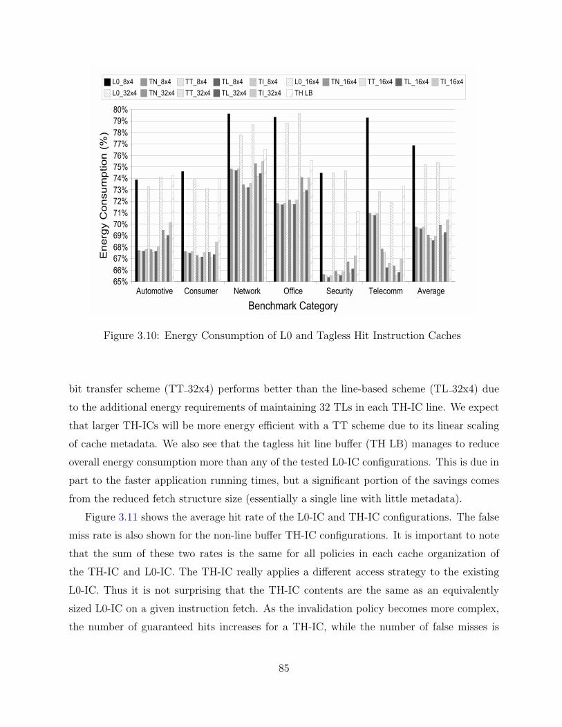
Figure 3.10: Energy Consumption of L0 and Tagless Hit Instruction Caches
bit transfer scheme (TT 32x4) performs better than the line-based scheme (TL 32x4) due
to the additional energy requirements of maintaining 32 TLs in each TH-IC line. We expect
that larger TH-ICs will be more energy efficient with a TT scheme due to its linear scaling
of cache metadata. We also see that the tagless hit line buffer (TH LB) manages to reduce
overall energy consumption more than any of the tested L0-IC configurations. This is due in
part to the faster application running times, but a significant portion of the savings comes
from the reduced fetch structure size (essentially a single line with little metadata).
Figure 3.11 shows the average hit rate of the L0-IC and TH-IC configurations. The false
miss rate is also shown for the non-line buffer TH-IC configurations. It is important to note
that the sum of these two rates is the same for all policies in each cache organization of
the TH-IC and L0-IC. The TH-IC really applies a different access strategy to the existing
L0-IC. Thus it is not surprising that the TH-IC contents are the same as an equivalently
sized L0-IC on a given instruction fetch. As the invalidation policy becomes more complex,
the number of guaranteed hits increases for a TH-IC, while the number of false misses is
85

Figure 3.11: Hit Rate of L0 and Tagless Hit Instruction Caches
correspondingly reduced. This is due to a reduction in the number of invalidations that were
overly conservative. Overall, however, we see that the hit rate for a TH-IC is competitive
with the hit rate of a comparably-sized L0-IC. Considering the relatively small false miss
rate, we see that the sample policies perform quite well, particularly the target-bit and line-
based transfer schemes. For instance, the TL 16x4 configuration has a hit rate of 84.99%,
while the L0 16x4 has a hit rate of 87.63%. More complicated policies could unnecessarily
increase energy utilization and overall circuit complexity. The TH LB has a hit rate of
approximately 67.62%, which shows that the majority of instructions fetched are sequential
and in the same line. False misses are not captured since they cannot be exploited in any
way by a line buffer.
Figure 3.12 compares the average power required of the instruction fetch stage of the
pipeline for the L0-IC and TH-IC configurations. The baseline case again is using only
an L1-IC and has an average power of 100%. These results are not surprising considering
the overall processor energy results already shown. However, this shows that the power
86

Figure 3.12: Fetch Power of L0 and Tagless Hit Instruction Caches
requirements for the TH-IC are considerably lower than an equivalently sized L0-IC. For
the best TH-IC configuration (TL 16x4), the fetch power is approximately 35.47% of the
baseline fetch power, while the corresponding 256-byte L0-IC yields only a 43.81% fetch
power. The average fetch power reduction comes from the elimination of cheaper tag/ID
comparisons on cache hits, as well as fewer ITLB accesses. The TH LB is able to reduce the
fetch power to 46.60%. This is a considerable savings for such a small piece of hardware, but
it is obvious that the higher miss rate (and thus increased number of L1 fetches) reduces the
energy efficiency below that achievable with a true TH-IC.
Energy-delay squared or ED2 is a composite metric that attempts to combine perfor-
mance and energy data together in a meaningful way. Energy is directly proportional to the
square of the voltage (E ∝ V 2), so decreasing the voltage reduces the energy of a processor,
but increases the clock period and hence execution time. Dynamic voltage scaling is one such
technique that reduces the clock rate in an effort to save energy [63]. ED2 is then used as
an indicator of a design’s relative performance and energy characteristics. Figure 3.13 shows
87
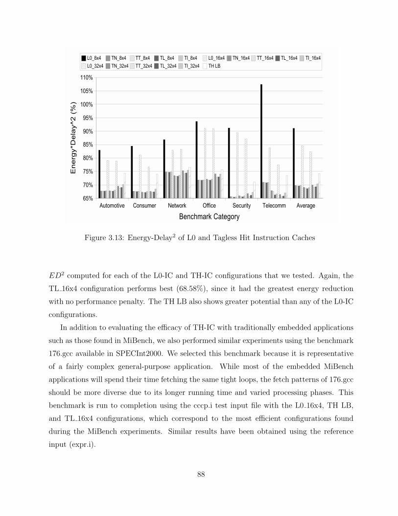
Figure 3.13: Energy-Delay2 of L0 and Tagless Hit Instruction Caches
ED2 computed for each of the L0-IC and TH-IC configurations that we tested. Again, the
TL 16x4 configuration performs best (68.58%), since it had the greatest energy reduction
with no performance penalty. The TH LB also shows greater potential than any of the L0-IC
configurations.
In addition to evaluating the efficacy of TH-IC with traditionally embedded applications
such as those found in MiBench, we also performed similar experiments using the benchmark
176.gcc available in SPECInt2000. We selected this benchmark because it is representative
of a fairly complex general-purpose application. While most of the embedded MiBench
applications will spend their time fetching the same tight loops, the fetch patterns of 176.gcc
should be more diverse due to its longer running time and varied processing phases. This
benchmark is run to completion using the cccp.i test input file with the L0 16x4, TH LB,
and TL 16x4 configurations, which correspond to the most efficient configurations found
during the MiBench experiments. Similar results have been obtained using the reference
input (expr.i).
88

Table 3.2: Comparing Fetch Efficiency Across Different Application Domains
MiBench Average 176.gcc from SPECInt2000L0 16x4 TH LB TL 16x4 L0 16x4 TH LB TL 16x4
Execution Cycles 106.50% 100.00% 100.00% 104.10% 100.00% 100.00%Total Energy 75.17% 74.13% 68.58% 83.81% 80.41% 79.03%Small Cache Hit Rate 87.63% 67.62% 84.96% 77.86% 66.61% 73.57%Fetch Power 43.81% 46.60% 35.47% 63.72% 58.33% 56.07%Energy-Delay Squared 84.57% 74.13% 68.58% 90.82% 80.41% 79.03%
Table 3.2 compares the average MiBench results with the experimental values we obtained
from running 176.gcc. The execution time penalty for using an L0-IC with 176.gcc (4.1%)
is lower than the MiBench average (6.5%). There is a clear difference in average fetch power
between 176.gcc and MiBench. With MiBench, the fetch power is lower because the hit rate
of the small cache is much higher. For 176.gcc, the guaranteed hit rate for the TH-IC is
73.57%, and adding false misses only brings the rate up to 77.86%, which is still much smaller
than the MiBench results (84.96% → 87.63%). Overall, the TL 16x4 TH-IC configuration
again outperforms both the TH LB and the traditional L0-IC in all aspects. Despite 176.gcc
having completely different data access patterns than our embedded applications, we see that
fetch behavior is still comparable, and thus TH-IC can be beneficial for processors running
general-purpose applications as well.
3.4 Identifying Application Behavior with TH-IC
The success that TH-IC has demonstrated in reducing instruction cache power consumption
has led us to examine how the same approach can be used to identify further opportunities
in pipeline optimization. To do this, it is important to understand how instructions are
flowing through the TH-IC. In order to get a better understanding of the abilities of TH-IC,
we took a closer look at the eviction behavior of the individual lines. The first study was
designed to identify how eviction was handled in a 16x4 TH-IC, which was the most energy
efficient configuration evaluated [34]. We collected statistics for each line evicted, counting
how many of the other 15 lines have been replaced since the last time the current cache line
was replaced. This information can shed some light on how the TH-IC is utilized. Figure 3.14
shows the results using an average of the MiBench benchmarks [27] described later in this
paper. Conflict misses occur when few lines are displaced between consecutive evictions of a
89

Figure 3.14: Line Replacements
single line. This is seen (and expected), but does not constitute the common case. Complete
cache replacement shows the highest individual frequency (22.48%), indicating a fairly large
number of capacity misses. This result is not particularly surprising for such a small cache,
but total cache line replacement of a direct mapped cache suggests a large loop structure
equal to or exceeding twice the size of the TH-IC or frequent changes in the working set. In
either case, we would expect that the miss behavior should be bimodal with some consecutive
TH-IC line misses as well as long periods of TH-IC hits. This is a nice feature since it means
that long sequences of instruction fetch should exhibit the same behavior.
Figure 3.15 shows both individual and cumulative results for consecutive hits in a 16x4
TH-IC. The graph shows values between 1 and 255+, with all consecutive streaks over
255 being collected under the 255+ data point. This data reinforces the observed eviction
behavior. We see two distinct spikes in the figure, at 3 instructions (28.28% ind. and 35.56%
cum.) and at 255+ instructions (26.91% ind.). The spike at 3 instructions shows standard
line buffer behavior – a miss on the first instruction in a line followed by 3 consecutive hits for
90
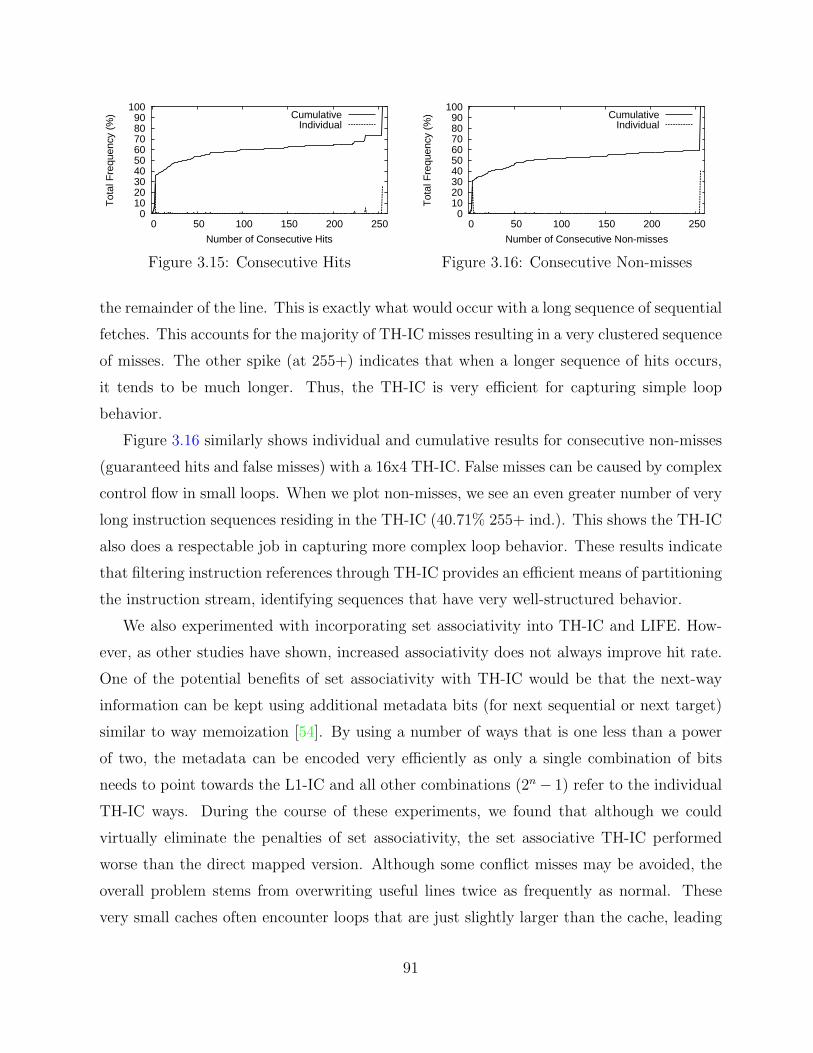
0 10 20 30 40 50 60 70 80 90
100
0 50 100 150 200 250
Tot
al F
requ
ency
(%
)
Number of Consecutive Hits
CumulativeIndividual
Figure 3.15: Consecutive Hits
0 10 20 30 40 50 60 70 80 90
100
0 50 100 150 200 250
Tot
al F
requ
ency
(%
)
Number of Consecutive Non-misses
CumulativeIndividual
Figure 3.16: Consecutive Non-misses
the remainder of the line. This is exactly what would occur with a long sequence of sequential
fetches. This accounts for the majority of TH-IC misses resulting in a very clustered sequence
of misses. The other spike (at 255+) indicates that when a longer sequence of hits occurs,
it tends to be much longer. Thus, the TH-IC is very efficient for capturing simple loop
behavior.
Figure 3.16 similarly shows individual and cumulative results for consecutive non-misses
(guaranteed hits and false misses) with a 16x4 TH-IC. False misses can be caused by complex
control flow in small loops. When we plot non-misses, we see an even greater number of very
long instruction sequences residing in the TH-IC (40.71% 255+ ind.). This shows the TH-IC
also does a respectable job in capturing more complex loop behavior. These results indicate
that filtering instruction references through TH-IC provides an efficient means of partitioning
the instruction stream, identifying sequences that have very well-structured behavior.
We also experimented with incorporating set associativity into TH-IC and LIFE. How-
ever, as other studies have shown, increased associativity does not always improve hit rate.
One of the potential benefits of set associativity with TH-IC would be that the next-way
information can be kept using additional metadata bits (for next sequential or next target)
similar to way memoization [54]. By using a number of ways that is one less than a power
of two, the metadata can be encoded very efficiently as only a single combination of bits
needs to point towards the L1-IC and all other combinations (2n− 1) refer to the individual
TH-IC ways. During the course of these experiments, we found that although we could
virtually eliminate the penalties of set associativity, the set associative TH-IC performed
worse than the direct mapped version. Although some conflict misses may be avoided, the
overall problem stems from overwriting useful lines twice as frequently as normal. These
very small caches often encounter loops that are just slightly larger than the cache, leading
91
to worst case behavior for both LRU and FIFO replacement policies. Even though other
studies of very small caches have used direct mapped purely as a simpler mechanism, our
analysis shows that direct mapped also provides better hit rates. The reduced number of
sets and the presence of loops that are larger than the small cache can result in worst-case
behavior for both LRU and FIFO replacement policies. It appears that set associativity is
not useful for very small instruction caches.
3.5 Eliminating Unnecessary BTB, BP, and RASAccesses
Although L1-IC energy tends to dominate the total energy required for the instruction fetch
pipeline stage, a TH-IC reduces this impact. We will show a TH-IC actually reduces the cache
power requirements so that it is less than the power consumed by the rest of instruction fetch.
LIFE is focused on making fetch more energy-conscious, and thus it becomes increasingly
important to reduce energy consumption in the remaining speculation components (BP,
BTB, RAS) present in instruction fetch. Based on our analysis of TH-IC residency in the
previous section, it is apparent that other microarchitectural state involved in fetch can
be managed more efficiently. Preliminary studies with LIFE revealed that 86.75% of the
executed instructions in our benchmarks are non-branch instructions, which means that
access to the BTB, BP, or RAS is unnecessary at least 86.75% of the time. Figures 3.15
and 3.16 make it clear that additional information can be kept regarding branch/non-branch
status of instructions, thus making a fetch engine more efficient.
LIFE employs both a conservative strategy and a more aggressive strategy for handling
access to speculative components of instruction fetch. The conservative strategy disables
speculation whenever the next fetched instruction can be guaranteed to not be a transfer of
control. Of the branches that are executed in an instruction stream, we found that 23.73%
are predicted strongly not-taken (state 00) by our bimodal branch predictor. The more
aggressive strategy will further disable speculation when the next fetched instruction is a
transfer of control, but has been previously predicted as strongly not-taken (00). Combined
together, the BTB, BP, and RAS structures need not be accessed for 89.89% of fetched
instructions.
LIFE depends on TH-IC to both supply and manage fetched instruction metadata.
Figure 3.17(a) shows the baseline TH-IC metadata configuration used in this paper. Each
92

Figure 3.17: LIFE Metadata Configurations
line is composed of four instructions and their associated NT bits. A single NS and valid
bit are associated with each line and 16 TL bits are used to facilitate line-based invalidation
of NTs. ID is 6 bits long to uniquely identify the corresponding L1-IC line (replacing the
longer tag of conventional caches), and only needs to be checked on a potential miss.
In Figure 3.17(b), a single Next Sequential Non-Branch bit (NSNB) has been added to
each instruction in the line. On sequential transitions both within and across lines, this
bit will be set when the next fetched instruction is not a transfer of control instruction.
Whenever this bit is set and we fetch sequentially, the BP, BTB, and RAS need not be
activated on the following cycle.
We can also extend the utilization of the NSNB bit to accept transfer of control
instructions that are strongly not-taken (approximately 23.73% of branches). This usage
will be referred to as NS00 due to 00 being the strongly not-taken bimodal BP state. In this
configuration, whenever a branch is encountered and a prediction is made that it is strongly
not-taken (state 00), the previous (sequential) instruction can set its NSNB bit. When this
instruction is later fetched, the NSNB bit will indicate that no prediction should be made.
While most branches that reach the strongly not-taken state remain not-taken, some of the
branches would suffer if their prediction remained not-taken while the instruction is in the
93

TH-IC. Since additional speculative misses would cause an increase in cycle count, selective
update of NS00 is necessary. On a branch misprediction, the TH-IC must be accessed to
unset the NS00 bit of the previous sequential instruction since we can no longer guarantee
that the branch will be predicted as not-taken.
Figure 3.17(c) is a further enhancement for LIFE that adds a single Next Target Non-
Branch bit (NTNB) for each instruction in the line. This bit serves a similar role as NSNB,
but it is set for branch instructions whenever the corresponding target instruction is not
a transfer of control or is strongly not-taken. Most branches do not target unconditional
jumps since compiler optimizations such as branch chaining can replace such a chain with a
single branch. Conditional branch instructions are also rarely targets, since they are typically
preceded by comparison instructions. Calls are rarely targets since they are usually preceded
by additional instructions to produce arguments. Finally, returns are rarely targets since
registers are often restored before the return. Thus, NTNB bits are generally quickly set for
each direct transfer of control. Again, this speculatively reduces the need to access the BP,
BTB, and RAS structures.
Adding these metadata bits to the TH-IC requires only a minor change in the steps to
take for line invalidation. When a line is evicted, all of its NSNB and NTNB bits must be
cleared. One interesting difference with the invalidation of NSNB versus the NS is that the
previous line’s last NSNB bit need not be cleared. This is due to the fact that any subsequent
fetch after crossing that line boundary will still not need a BP/BTB/RAS access, as that
instruction will not change branch status whether it was fetched from L1-IC or TH-IC. This
same principle holds for NTNB bits when NT bits are cleared due to target line evictions.
Figure 3.18 shows an example of using LIFE to fetch a loop. This example includes both
the NSNB and NTNB extensions. We track the number of BTB/BP/RAS accesses required
in addition to the L1-IC and ITLB accesses. The baseline loop sets the appropriate NS and
NT bits as the instructions are initially fetched from the L1-IC. Each of the instructions in the
main loop (2–7) can be guaranteed to hit in the TH-IC once the NS and NT links have been
set, thus leading to extremely efficient cache behavior during the steady state operation.
NSNB and NTNB bits are correspondingly set as LIFE gathers information about the
instructions fetched in the loop. During subsequent loop executions, the BTB/BP/RAS need
only be accessed when instruction 7 is fetched, thus leading to only one single speculation
access per loop iteration. Without NTNB bits, the fetch of instruction 2 would also require a
94

SteadyStateLoopBehavior
fetched
inst 1
inst 5
insts 6,7
inst 2
insts 3,4
inst 5
false miss
false miss
miss
miss
hits
hits
result
inst 1
inst 2
inst 3
inst 4
inst 5
inst 6
inst 7
inst 8
...
...
line
1lin
e 2
metadata set
set line 0 NS bit; set prev NSNB bit
set line 1 NS bit; set inst 4 NSNB bit
set inst 2,3 NSNB bits
inst 6 hit
hitinst 7
inst 2 hit
insts 3,4 hits
set inst 7 NT bit; set inst 7 NTNB bit
set inst 1 NT bit; set inst 1 NTNB bit
set inst 5 NSNB bit
insts 5,6 hits
inst 7 hit
hitinst 8 set inst 7 NSNB bit
L1/ITLB? BTB/BP/RAS?
Figure 3.18: Reducing BTB/BP/RAS Accesses Example
BTB/BP/RAS access, since the branch transition from instruction 7 could not be guaranteed
to target a non-branch.
Modifying the use of speculative components requires an understanding of the regularity
in which these components are used and their results relative to the TH-IC. Figure 3.19
shows the taxonomy of branches as they are fetched using LIFE with NSNB, NS00, and
NTNB extensions. This figure clearly demonstrates the correlation of speculative hardware
with the fetch of instructions. We find that 56.48% (45.92% taken + 10.56% not-taken) of
all branches will have their predicted next instruction as a guaranteed hit in the TH-IC.
Further, 58.61% of all branches will have metadata available at fetch1. Combined, we find
that almost all branches with metadata result in a guaranteed hit in the TH-IC. This fact
could potentially lead to the discovery of new relevant metadata that could further influence
speculative execution. A somewhat intuitive step was to enhance LIFE with speculative
information. Unfortunately, as can be seen in Figure 3.19, 41.39% (11.94% from L1 +
29.45% first access) of branches either are not fetched from the TH-IC or do not contain
metadata. This means that the smaller structure of an embedded BTB and branch predictor
would be applicable to only 58.61% of branches. The level of accuracy obtained did not offset
1For a branch to be considered as having metadata it must not be the first fetch of the given branch. Ifa TH-IC line eviction occurs and the branch leaves the TH-IC, then the next fetch of that branch will beconsidered its first fetch since the metadata was cleared.
95
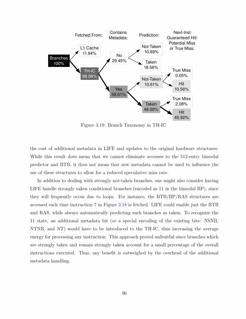
Figure 3.19: Branch Taxonomy in TH-IC
the cost of additional metadata in LIFE and updates to the original hardware structures.
While this result does mean that we cannot eliminate accesses to the 512-entry bimodal
predictor and BTB, it does not mean that new metadata cannot be used to influence the
use of these structures to allow for a reduced speculative miss rate.
In addition to dealing with strongly not-taken branches, one might also consider having
LIFE handle strongly taken conditional branches (encoded as 11 in the bimodal BP), since
they will frequently occur due to loops. For instance, the BTB/BP/RAS structures are
accessed each time instruction 7 in Figure 3.18 is fetched. LIFE could enable just the BTB
and RAS, while always automatically predicting such branches as taken. To recognize the
11 state, an additional metadata bit (or a special encoding of the existing bits: NSNB,
NTNB, and NT) would have to be introduced to the TH-IC, thus increasing the average
energy for processing any instruction. This approach proved unfruitful since branches which
are strongly taken and remain strongly taken account for a small percentage of the overall
instructions executed. Thus, any benefit is outweighed by the overhead of the additional
metadata handling.
96

Table 3.3: Baseline LIFE ConfigurationI-Fetch Queue 4 entriesBranch Predictor Bimodal – 512Branch Target Buffer 512 entriesBranch Penalty 3 cyclesReturn Address Stack 8 entriesFetch/Decode/Issue/Commit 1Issue Style In orderRUU size 8 entriesLSQ size 8 entries
16 KBL1 Data Cache 256 lines, 16 B line,
4-way assoc., 1 cycle hit16 KB
L1 Instruction Cache 256 lines, 16 B line,4-way assoc., 1 cycle hit
Instruction/Data TLB 32 entries, Fully assoc.,1 cycle hit
Memory Latency 32 cyclesInteger ALUs 1Integer MUL/DIV 1Memory Ports 1FP ALUs 1FP MUL/DIV 1
256BL0 Instruction Cache 16 lines, 16B line,(when configured) direct mapped, 1 cycle hit
256BTagless Hit I-Cache 16 lines, 16B line,(when configured) direct mapped, 1 cycle hit
Line-based invalidation
3.6 Experimental Evaluation of LIFE
Table 3.3 shows the exact configuration parameters that were used in each of the experiments.
The L0-IC and TH-IC are only configured when specified in the evaluation. We evaluate
using just TH-IC and then extend it with the LIFE techniques for eliminating BP, BTB, and
RAS accesses. In subsequent graphs, NSNB indicates using the NSNB bits only to handle
instructions that are not transfers of control, while NS00 corresponds to a configuration that
uses the NSNB bits to handle strongly not-taken branches as well. Finally, NTNB includes
NSNB, NS00, and adds NTNB bits to handle targets that are not transfers of control.
While the Wattch power model is only an approximation, it is sufficient for providing
reasonably accurate estimates for simple cache structures using CACTI [79]. The structures
being evaluated in this work (TH-IC, BP, BTB, RAS, L0-IC, L1-IC, ITLB) are composed
primarily of simple regular cache blocks and associated tags/metadata. Although L0-IC and
TH-IC may differ in functionality (tag checks vs. metadata updates), they should remain
very similar in overall latency and area. Writing of metadata bits can be viewed as a small
register update, since the overall bit length is often short.
We again employ the MiBench benchmark suite to evaluate our design. We also present
results for the 176.gcc benchmark available in SPECInt2000 in order to evaluate the impact of
LIFE on a more complex general purpose application. This benchmark is run to completion
using its test input file (cccp.i). We have obtained similar results using the reference input
(expr.i). MiBench results are presented by category along with an average due to space
constraints. All results for 176.gcc are displayed after the MiBench average. Results are
97
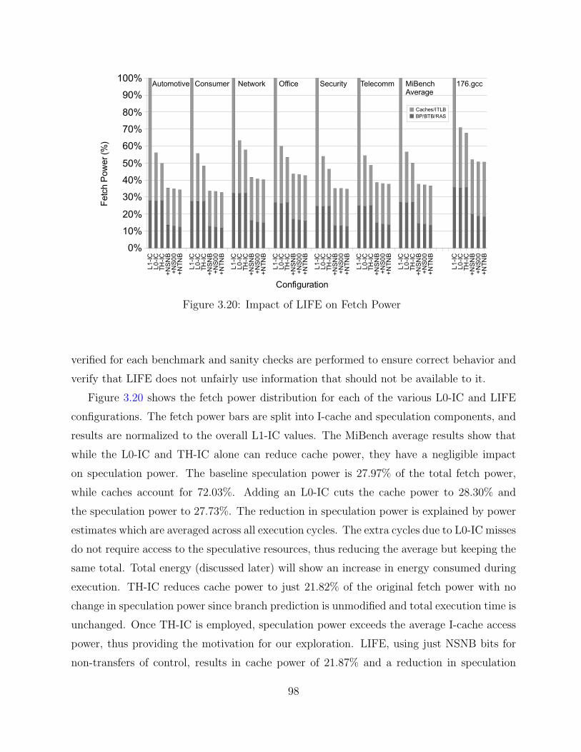
Figure 3.20: Impact of LIFE on Fetch Power
verified for each benchmark and sanity checks are performed to ensure correct behavior and
verify that LIFE does not unfairly use information that should not be available to it.
Figure 3.20 shows the fetch power distribution for each of the various L0-IC and LIFE
configurations. The fetch power bars are split into I-cache and speculation components, and
results are normalized to the overall L1-IC values. The MiBench average results show that
while the L0-IC and TH-IC alone can reduce cache power, they have a negligible impact
on speculation power. The baseline speculation power is 27.97% of the total fetch power,
while caches account for 72.03%. Adding an L0-IC cuts the cache power to 28.30% and
the speculation power to 27.73%. The reduction in speculation power is explained by power
estimates which are averaged across all execution cycles. The extra cycles due to L0-IC misses
do not require access to the speculative resources, thus reducing the average but keeping the
same total. Total energy (discussed later) will show an increase in energy consumed during
execution. TH-IC reduces cache power to just 21.82% of the original fetch power with no
change in speculation power since branch prediction is unmodified and total execution time is
unchanged. Once TH-IC is employed, speculation power exceeds the average I-cache access
power, thus providing the motivation for our exploration. LIFE, using just NSNB bits for
non-transfers of control, results in cache power of 21.87% and a reduction in speculation
98

power to 13.55%. The cache power is slightly increased from the baseline LIFE with TH-IC
due to additional NSNB bits and associated upkeep. Allowing strongly not-taken branches
(NS00) results in a 13.06% speculation power and 21.91% cache power. Finally, adding the
NTNB bits reduces the speculation power to 12.34% and the cache power to 21.95%, for an
overall fetch power savings of 65.70% over the baseline L1-IC. LIFE eliminates an average
of 61.17% of speculative hardware accesses due to being able to exploit the NSNB/NTNB
metadata. Results for 176.gcc show slightly reduced but still significant savings in fetch
power for LIFE.
While an L0-IC degrades performance by about 6.44% (with a 17.67% maximum increase
on rijndael), TH-IC and LIFE have no associated performance penalty. The baseline TH-IC
as well as LIFE with any of the configured NSNB, NS00, or NTNB extensions do not exhibit
any associated performance difference from the baseline configuration.
Figure 3.21 shows the benefit of LIFE on total processor energy. Adding an L0-IC reduces
total energy to 79.00%. This is less than the power savings because total energy accounts for
the increase in execution time caused by the increased L1-IC latency when servicing L0-IC
misses. TH-IC cuts total energy to 72.23%, in line with power analysis since execution time
is unaffected. Similarly, LIFE with NSNB reduces total energy to 65.44%, in line with power
estimates. Adding NS00 reduces the total energy to 65.27% and NTNB yields a final total
processor energy of 64.98%. With 176.gcc, applying all the LIFE extensions reduces the total
energy to 72.88%. In all cases, LIFE extensions are able to achieve equivalent power reduction
in speculation components that TH-IC achieved with the I-cache/ITLB. The combination of
these enhancements yields a much greater energy savings than any other existing instruction
fetch energy reduction technique evaluated.
3.7 Improving Next Sequential Line Prefetch withLIFE
LIFE is designed to exploit program fetch behavior in an effort to better utilize pipeline re-
sources. In examining the functionality of the TH-IC, we found that presence of instructions
in the TH-IC can be used as a simple execution phase predictor. When instructions are
fetched from the TH-IC, they are identified as being part of very regular instruction fetch.
This regularity of fetch behavior can identify potential optimizations in later pipeline stages
either to improve execution performance or to reduce power consumption. There have been
99
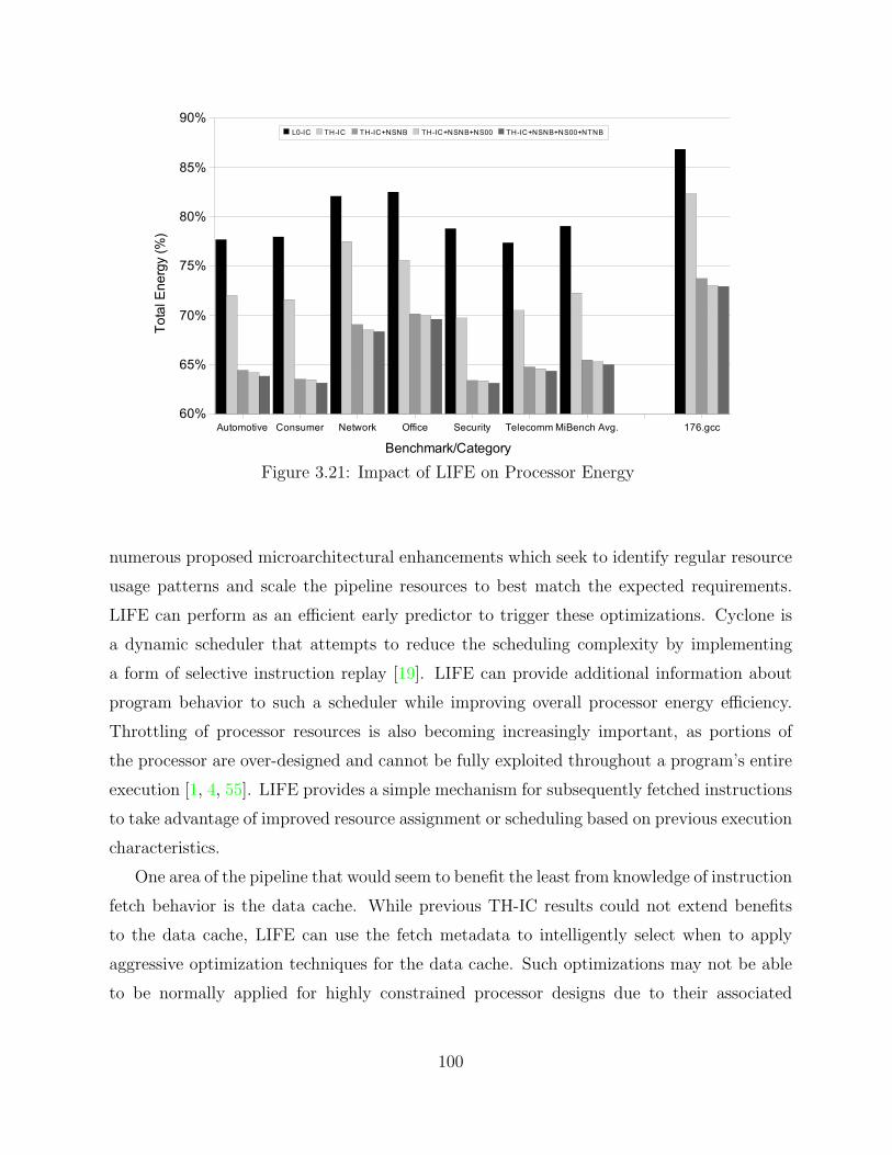
Figure 3.21: Impact of LIFE on Processor Energy
numerous proposed microarchitectural enhancements which seek to identify regular resource
usage patterns and scale the pipeline resources to best match the expected requirements.
LIFE can perform as an efficient early predictor to trigger these optimizations. Cyclone is
a dynamic scheduler that attempts to reduce the scheduling complexity by implementing
a form of selective instruction replay [19]. LIFE can provide additional information about
program behavior to such a scheduler while improving overall processor energy efficiency.
Throttling of processor resources is also becoming increasingly important, as portions of
the processor are over-designed and cannot be fully exploited throughout a program’s entire
execution [1, 4, 55]. LIFE provides a simple mechanism for subsequently fetched instructions
to take advantage of improved resource assignment or scheduling based on previous execution
characteristics.
One area of the pipeline that would seem to benefit the least from knowledge of instruction
fetch behavior is the data cache. While previous TH-IC results could not extend benefits
to the data cache, LIFE can use the fetch metadata to intelligently select when to apply
aggressive optimization techniques for the data cache. Such optimizations may not be able
to be normally applied for highly constrained processor designs due to their associated
100

tradeoffs. Prefetching is an example of such an aggressive optimization that attempts to
reduce cache miss penalties by using idle cache cycles to fetch data speculatively from
predicted addresses. When a triggering condition is met, the cache will prefetch an additional
line of data. Although prefetching can improve performance through reducing cache misses,
it significantly increases memory traffic and may force the early eviction of other cache lines
that are still useful, thus polluting the cache. With next sequential line prefetching (NSLP),
the first non-prefetch access of a line triggers the next sequential line to be fetched from
memory once the current cache access operation has finished [25, 70, 72]. By associating a
first access bit with each cache line, a subsequent true use of a prefetched line triggers the
next sequential line to be prefetched. This technique potentially allows the prefetching to
stay one line ahead of the current accesses. If a line is already available in the cache, then
the data is not fetched from memory unnecessarily.
Although LIFE only keeps track of instruction fetch behavior, we can exploit this
information to have NSLP selectively enabled or disabled. NSLP works best on sequentially
accessed arrays that exhibit a good deal of spatial locality. Small loops are often used to
iterate through arrays of data, and LIFE can provide a simple mechanism for detecting
such loops. We can use a single bit to denote whether the initial line access was a hit or
a miss, which we will refer to as the TH-IC line-hit bit. It is possible for a TH-IC line-hit
access to not be in a small loop, but the majority of cases will show that this fetch behavior
corresponds to the execution of a small loop. Thus we can enable NSLP when we have a TH-
IC line-hit and disable it on any miss. The TH-IC line-hit information will be propagated
through the various pipeline stages with the fetched instruction and will only be checked if
the instruction is a memory access.
Throttling the NSLP mechanism will help to reduce the frequency of useless prefetches.
This approach conserves energy and can also help to reduce cache pollution for benchmarks
that typically do not exhibit good prefetch behaviors. Table 3.4 presents a simplified
view of the combinations of instruction and data flow behavior in a pipelined processor.
Both instruction and data flow can be simply characterized as stable or unstable. Stable
instruction flow corresponds to loop behavior where the instruction sequences are able to be
fetched from a small cache. Stable data flow indicates a data access pattern that exhibits
good spatial locality, possibly improving with prefetching. LIFE and TH-IC can provide their
greatest benefits during periods of stable instruction flow as they rely on past instruction
101

Table 3.4: Correlating Instruction and Data Flow Behavior
Inst. Flow Data Flow Comments
Stable Stable Typical loop (strided array data accesses)Stable Unstable Typical loop (pointer-chasing data accesses)Unstable Stable Does not occur often in practiceUnstable Unstable Transitional code (non-loop)
Table 3.5: Impact of LIFE with Next Sequential Line Prefetch
Useless Prefetches Execution TimeNSLP LIFE+NSLP NSLP LIFE+NSLP
Automotive 34.52% 31.85% 93.61% 94.39%Consumer 25.15% 16.27% 97.00% 97.60%Network 38.02% 25.23% 95.95% 96.14%Office 49.43% 29.01% 98.05% 98.53%Security 52.26% 36.99% 99.96% 99.96%Telecomm 22.36% 27.17% 99.86% 99.88%MiBench Avg. 36.82% 28.52% 97.54% 97.88%176.gcc 51.31% 38.17% 97.61% 98.79%
behavior to make guarantees. NSLP only provides benefits during periods of stable data
flow. When data flow is unstable, NSLP performs useless prefetches that waste energy and
can evict useful cache lines. The majority of program execution time in most applications
will consist of stable instruction flow (or typical loop behavior).
Table 3.5 summarizes the results of our experiments with LIFE and next sequential line
prefetch. Useless prefetches denotes the fraction of prefetches that are never accessed by
the actual application before being evicted. NSLP reduces the overall application execution
times, while LIFE+NSLP can attain most of the benefits by just selectively prefetching.
For MiBench, the number of useless prefetches is reduced by 22.54% when applying NSLP
selectively based on LIFE metadata. With 176.gcc, the use of LIFE reduces the useless
prefetches by an additional 25.6%. This translates into a significant reduction in memory
traffic due to data access. Wattch does not model the off-chip energy consumption of main
memory, so energy results are not included. Simplified energy analysis based on memory
access counts shows that LIFE+NSLP results in an overall greater system energy savings
than NSLP alone.
102
3.8 Concluding Remarks
L0/filter instruction caches can greatly reduce the energy consumption of a processor by
allowing the most frequent instructions to be accessed in a more efficient manner. However,
L0-IC misses can accumulate and lead to significant application slowdown. In this chapter,
we described the Tagless Hit instruction cache, a small IC that does not require a tag/ID
comparison or ITLB access to be performed on cache hits. The TH-IC is designed to
take advantage of the properties of a small direct-mapped instruction cache and common
instruction fetch behaviors. The reason that a TH-IC works is that it can identify nearly all
of the accesses that will be hits in the cache before the instructions are fetched. The L0-IC
impacts performance because trying to capture the few remaining accesses (false misses as
hits) comes at the cost of a cycle of latency for all L0-IC misses. The TH-IC features a hit
rate that is competitive with that of a similarly sized L0-IC (because there are not many
false misses). Furthermore, the TH-IC can be bypassed during fetch when an instruction
is not guaranteed to reside in one of the cache lines, eliminating the performance penalty
normally associated with small instruction caches that can’t be bypassed, like L0. Some TH-
IC configurations require fewer metadata bits than a corresponding L0-IC, and even the larger
TH-IC configurations require only a few extra bits per line. We also designed a compact
line buffer based on the same principles as the TH-IC that provides better performance
and energy efficiency than any L0-IC at a fraction of the area requirement. By exploiting
fetch behavior, the TH-IC provides an attractive solution for improving processor energy
efficiency without any negative performance impact or additional programmer effort. The
TH-IC is even desirable for general-purpose processors as power and heat issues have become
more of a concern. Even though execution characteristics of general-purpose applications
tend to be more diverse, fetch behavior remains similar and can thus be exploited by the
TH-IC. The lack of any additional miss penalty makes the TH-IC a viable alternative for
high-performance processors, something which could not be said of the L0-IC.
We have also demonstrated how instruction fetch power utilization can be improved
by exploiting those portions of the program execution that exhibit significant regularity.
The goal of the LIFE extensions to the processor fetch logic is to identify repetitive code
sequences and cache enough information about their prior behavior to control access to the
BP, BTB, and RAS structures. LIFE eliminates access to these structures an average of
103
61.17% of the time, resulting in a total savings of 63.33% on instruction fetch power and
an additional savings of 9.42% on total processor energy beyond what is achievable with
TH-IC alone. All of these improvements are made with no increase in execution time and
require only 128 additional metadata bits (2 bits per TH-IC instruction). Furthermore,
we showed that this enhanced knowledge of instruction fetch behavior can guide other
pipeline decisions, particularly for handling aggressive optimizations like next sequential
line prefetch. By focusing on the loops detected by LIFE, we were able to reduce the
number of useless data prefetches while still maintaining the majority of the performance
benefit afforded by prefetching. Other throttling techniques may benefit similarly from the
phase behaviors detected by LIFE. The design complexity of TH-IC and LIFE is minimal,
with an area cost comparable to similar conventional filter caches using a few simple index
structures to maintain the metadata required to control resource allocation. LIFE can
easily be incorporated into any processor pipeline, requiring only minor additions to the
fetch stage and the routing of branch outcomes to update the LIFE metadata. We believe
that these techniques can become a common design choice for both low-power embedded
processors as well as high-performance general purpose processors. This will become even
more important as multicore architects focus their efforts towards further reducing per core
power consumption.
104

CHAPTER 4
Related Work
There are three primary design constraints that embedded processor developers must face:
energy consumption, code size and execution time. Design enhancements are often focused
on these particular areas of development. It is often that a single technique will benefit
one or more of these areas at the expense of some other design constraint. Techniques that
target code size reduction typically increase the execution time of an application. Similarly,
techniques that focus on reducing energy consumption often increase execution time and/or
code size, since they often work with reduced hardware resources. Finally, techniques for
improving execution time often sacrifice code size as well as energy efficiency, in order to
obtain peak performance.
4.1 Reducing Energy Consumption
Energy consumption is a prime concern for embedded processor designers, as these devices
must often operate on battery power. Instruction fetch has been shown to account for up to
one-third of the total processor power expenditure per cycle on a StrongARM SA-110 [56].
In order to reduce fetch energy consumption, processor designers have developed techniques
to improve the fetch of instructions in loops, enhance existing cache mechanisms, as well as
dynamically adjust the voltage of a processor at run-time.
It is apparent that the majority of instructions executed for a general purpose application
come from the application’s inner loops. Specialized hardware can be developed to improve
the fetch of instructions from these inner loops. The zero-overhead loop buffer (ZOLB) is a
small compiler-managed instruction cache, where an innermost loop can be explicitly loaded
and executed [20]. Special instructions are used to specify the loading of the loop, and the
number of iterations to execute. After performing the sequence the requested number of
105

times, the program returns to its standard method for fetching and executing instructions.
A ZOLB can reduce fetch energy (since the IC can be bypassed), as well as result in reduced
execution time due to not having to execute loop test and branch instructions.
Loop caches are small dynamically-managed instruction buffers that can also reduce fetch
energy requirements for innermost loops [49]. These caches operate by detecting an initial
short backward branch (sbb) in the code. When this happens, the loop cache begins filling
with instructions until the same sbb is encountered and taken again. If this sbb is not taken
or another transfer of control is taken, then filling is terminated and the loop cache goes
back to its idle state. If however, the same sbb is taken, instructions can now be fetched
and executed directly from the loop cache, until the sbb is no longer taken, or a different
transfer of control is taken. Normally the loop must fit in the buffer provided by the loop
cache, although techniques have been developed to allow for partial fetches of larger loops
to occur [50]. It is also possible to pre-load a loop cache with several frequently executed
small loops for execution at run-time [26].
Data and instruction caches are often separated for performance reasons, particularly
with respect to handling the diverse behavior and request patterns for each. The L-
cache seeks to further subdivide the instruction cache into categories based on execution
frequency [5, 6]. The frequently executed loops in code are placed into the low-power L-cache,
which can be distinguished by address space location, while the infrequent code is placed
in a standard instruction cache. Despite the additional instruction costs for restructuring
control flow to use an L-cache, this approach reduces both fetch energy and execution time.
Region-based caching subdivides the first-level data cache into separate partitions for the
stack, heap, and global variable storage [48]. Individual partitions can then be specialized
to best handle their particular category of memory accesses. This results in reduced energy
consumption and improved performance. The Stack Value File is one particular example of
a partition that is tuned for stack memory accesses [47]. The SVF routes accesses to the
topmost portion of the stack through a special circular register file, thus reducing memory
contention for the traditional data cache and improving overall system performance.
Another simple technique for reducing fetch energy is the use of a small direct-mapped L0
or filter instruction cache [40, 41]. The small size of the L0 cache results in a net reduction
in fetch energy for the most frequently executed loop instructions. The drawback for L0
caches, however is the high miss rate, which leads to performance penalties, even if the L1
106
cache access is a hit on the following cycle.
There has also been some previous work to decide whether the filter cache or the L1-IC
should be accessed on a particular fetch. A predictive filter cache has been developed to allow
direct access to the L1-IC without accessing a filter cache first for accesses that are likely to
be filter cache misses [75, 74]. A dynamic prediction is made regarding whether or not the
subsequent fetch address is in the filter cache. This prediction is accomplished by storing
for each line the four least significant tag bits for the next line that is accessed after current
line. When an instruction is being fetched, these four bits are compared to the corresponding
bits for the current instruction’s tag. These bits will often be identical when consecutive
lines are accessed in a small loop. Significant energy savings were obtained with a slight
performance degradation by accessing the L1-IC directly when these bits differ. Conventional
tag comparisons and the additional 4-bit comparison are both required for the predictive filter
cache. The HotSpot cache uses dynamic profiling to determine when blocks of instructions
should be loaded into the filter cache based on the frequency of executed branches [81].
Instructions are fetched from the L0-IC as long as hot branches are encountered and there
are no L0-IC misses. Like the predictive filter cache, the HotSpot cache also requires a tag
comparison to be made for each L0 access. In contrast, the TH-IC requires no tag comparison
for guaranteed hits and only a small ID comparison for potential misses. This should result
in reduced energy consumption compared to both of these approaches.
There has also been previous research on guaranteeing hits in an L1-IC. The goal for these
caches is to reduce energy consumption by avoiding unnecessary tag checks in the L1-IC.
Way memoization was used to guarantee that the next predicted way within a 64-way L1-IC
is in cache [54]. Valid bits are used to guarantee that the next sequential line accessed or line
associated with the target of a direct transfer of control are in cache. Different invalidation
policies were also investigated. When the next instruction is guaranteed to be in cache, 64
simultaneous tag comparisons are avoided. The history-based tag-comparison (HBTC) cache
uses a related approach. It stores in the BTB an execution footprint, which indicates if the
next instruction to be fetched resides in the L1-IC [38, 37]. These footprints are invalidated
whenever an L1-IC miss occurs. Rather than guaranteeing hits in a conventional L1-IC, we
believe that the most beneficial level to guarantee hits is within a small instruction cache.
First, most of the instructions fetched can be guaranteed to be resident in the small IC,
which will result in a smaller percentage of guaranteed hits in an L1-IC. Since the L1-IC will
107

be accessed fewer times in the presence of a small instruction cache, the additional metadata
bits in the L1-IC will be costly due to the increased static versus dynamic energy expended.
Second, the invalidation of metadata when a line is replaced is much cheaper in a small IC
since there are fewer bits of metadata to invalidate.
Reinman et al. propose a serial prefetch architecture that splits tag and data accesses
into separate pipeline stages for instruction fetch [65]. By performing tag accesses first,
only the relevant data line from the proper cache way needs to be fetched, saving processor
energy. By fetching ahead with the tags, instruction lines can be prefetched into a special
buffer from which they can later be promoted to the actual instruction cache on a direct fetch
request, thus improving performance. In contrast, LIFE completely eliminates tag accesses
for guaranteed hits, and also reduces the number of accesses to other fetch structures relating
to speculation, which serial prefetching cannot do.
There has also been some previous work on reducing the energy consumption of the BTB.
Utilizing banked branch prediction organization along with a prediction probe detection to
identify cache lines containing no conditional branches was evaluated by Parikh et al. [60].
This study showed that careful layout of branch predictor resources and a course granularity
bypass capability can make much larger branch predictors feasible from a total energy
perspective. Just as there are fewer bits of metadata to manage in a TH-IC versus an
L1-IC to guarantee hits, it is also more efficient to avoid accesses to the BP/BTB/RAS by
tracking this information in a small TH-IC versus a larger structure for the entire BTB. A
leakage power reduction technique has also been used to turn off entries in the BP and BTB
if they are not accessed for a specified number of cycles [36]. The counters used will limit
the amount of energy savings. Yang et al. reduce BTB energy consumption by altering the
instruction set and producing setup code to store the distance to the next branch instruction
from the beginning of each basic block in a small branch identification unit [80]. The BTB
is not accessed until the next branch is encountered. While reducing energy consumption,
this approach requires alteration of the executable to store the branch distance information
and a counter to detect when the next branch will be encountered.
There are a variety of power-saving techniques that can be applied to traditional
instruction cache designs. Block buffering [73] allows large cache lines to be accessed in a
manner similar to the L0 cache previously described. Cache sub-banking [73] and Multiple-
Divided Modules [43] focus on separating the address space using several individual caches.
108

Gray code addressing [73] seeks to minimize the bit-switching activity found on address lines
in an instruction cache.
Dynamic voltage scaling (DVS) is a technique that seeks to reduce energy consumption of
a device by reducing the voltage of the device during periods of idle usage [63]. Since energy
is directly proportional to the square of the voltage, this technique can yield significant
energy savings. Although the benefits of this technique are quite high, the penalty is in
increased execution time, as well as the requirement for a compliant operating system that
can adequately predict run-time needs of its various applications.
4.2 Reducing Code Size
Static code size is another important metric for embedded processor design, since code
size reductions can decrease memory requirements and thus ROM/memory component
costs. Code size reducing techniques can be grouped as abstraction techniques, dictionary
compression techniques, or ISA-modifying enhancements. Abstraction techniques, such as
procedural abstraction [22, 13, 17] and echo factoring [46], focus on replacing repeated
sequences of code with special call instructions to new subroutines. These new subroutines
contain the abstracted redundant code. Such techniques lead to reduced code size at the
expense of reduced spatial locality (due to the increased number of calls/returns).
Dictionary compression techniques [52, 2, 14, 15] focus on replacing sequences of repeated
instructions with shorter keywords. These keywords can be looked up during execution and
the appropriately mapped instruction sequence can be executed in its place. These techniques
reduce code size significantly, but can negatively impact execution time due to the dictionary
lookups, as well as requiring additional die area, resulting in increased energy requirements.
ISA-modifying enhancements can also be used to reduce the code size of an application.
Many modern embedded processors now offer dual-width instruction sets such as the
ARM/Thumb [67] and MIPS16 [42]. These instruction sets support an additional 16-bit
ISA which is used to compress infrequently executed instruction sequences. These secondary
ISAs can only access a small subset of opcodes, registers and immediate values, so they will
yield reduced performance if executed frequently. Instead, profiling is often used to keep the
frequent code using 32-bit instructions and infrequent code using 16-bit instructions [44].
Augmenting eXtensions (AX) have been designed to enhance the use of dual-width ISAs like
the ARM/Thumb [45]. AXThumb allows multiple 16-bit instructions to be coalesced into
109

more expressive 32-bit instructions for improved execution in 16-bit Thumb mode. Thumb-
2 [64] is similar to AXThumb, as it attempts to reduce the performance penalty associated
with 16-bit code by introducing some 32-bit instructions.
Another ISA-modifying enhancement is support for variable-length instructions, which
can be used to compress simple and frequent operations to a greater extent. The primary
drawback of variable-length instruction sets is the increased pressure on instruction decode,
due to alignment issues. Heads and Tails [59] is an enhancement to traditional variable-length
ISAs, since it focuses on reducing this alignment penalty. In this architecture, instructions are
split into fixed-length opcode heads and variable-length operand tails. Multiple instruction
heads are placed at the start of an instruction bundle, while the corresponding tails are
placed in reverse order at the back of the bundle. This allows the heads to be fetched and
decoded in parallel, while the tails are still unknown. Although the Heads and Tails scheme
does reduce the static code size of an application, there are still some performance and energy
implications involved in decoding the bundles efficiently.
4.3 Reducing Execution Time
Many techniques can also be used to reduce the overall execution time of embedded
applications. These techniques include specialized instruction sets and addressing modes
to increase instruction efficiency and throughput. The ability to coalesce sequential depen-
dent instruction sequences has also become very popular for improving processor resource
utilization and throughput. Additionally, a new architecture has been developed that seeks to
exploit the varying benefits of existing superscalar, VLIW and vector processing approaches.
Instruction set architectures sometimes include special-purpose instructions for use in
particular applications or performance-critical kernels. Recent processor design trends have
increased the popularity of single-instruction multiple data (SIMD) extensions [62, 51, 18].
These extensions improve the throughput of multimedia applications, which often repeat
many simple operations on streams of data. Application-specific instruction-set processors
or ASIPs exemplify the general approach of producing an ISA that is custom-tailored for a
specific task [53, 11]. In such a system, the hardware and software are co-designed in order
to appropriately balance code size, performance, and energy requirements.
Specialized addressing modes can also be used to reduce the execution time of a particular
application. Two of the most popular addressing modes for DSP algorithms are modulo
110
addressing [57, 78] and bit-reversed addressing [57, 66]. Without the use of these specialized
addressing modes, additional instructions would be necessary to carry out the address
calculation before performing various load and store operations for applications that make
use of filtering and Fast Fourier Transforms (FFTs).
Similar to ASIP design, another technique for improving performance is the detection of
dependent instruction sequences that can be collapsed into new instructions with reduced
cycle times. This detection and coalescing is often referred to as dataflow sub-graph com-
paction. Specialized hardware is programmed to effectively carry out complex calculations
using these compacted sub-graphs. Dataflow mini-graphs are simple multi-instruction sub-
graphs, with at most two inputs, one output, one memory reference and one transfer of
control [8]. These mini-graphs are extracted from an application and placed into a mini-
graph table, which can then be accessed by a special instruction to carry out the required
dataflow operations. This ability not only reduces the cycle time of complex instruction
sequences, but can also reduce the pipeline resources necessary for carrying out such an
operation.
Clark et al. have developed another architectural feature called CCA (configurable
compute accelerator), that executes dataflow sub-graphs for improved performance in
embedded systems [12]. The difference between CCA and dataflow mini-graphs is that the
code for the sub-graph is actually a procedurally abstracted routine that can be dynamically
compiled for the hardware at run-time. A configuration cache helps in keeping the frequently
accessed sub-graph configurations from needing to be re-configured when they are executed.
One of the primary benefits over dataflow mini-graphs is that the underlying processor
technology can support different degrees of complexity for CCA, since the sub-graphs can
be executed as a standard subroutine in the worst case.
111

CHAPTER 5
Future Work
This chapter describes some potential areas for future exploration with regards to improving
the efficiency of instruction fetch. We explore some potential directions for integrating
instruction packing with a few modern embedded processor designs. We also outline some
of the ways in which LIFE can be used to improve other pipeline decisions by guaranteeing
particular fetch properties.
5.1 Improvements for Instruction Packing
5.1.1 Splitting of MISA and RISA
Our work with the IRF and Instruction Packing uses a modified version of the MIPS/Pisa
architecture. This ISA was chosen for its simplicity, as well as the availability of high-
quality code generation and simulation tools. Similar to ARM/Thumb [67], the MISA and
RISA can be divided into two distinct ISAs with differing instruction sizes. A 16-bit 2-
address MISA would allow for significant code size reductions, similar to the Thumb mode
of ARM processors. The RISA would likely be a 32-bit 3-address instruction set focused
on improving performance. Combining the compression-oriented MISA with an expressive
RISA would yield improved energy utilization and code size.
One of the primary limitations of Thumb mode execution is the reduced expressiveness
of the instruction set. This often leads to increased execution time, since multiple simpler
instructions may be required to semantically match a more complex single ARM instruction.
Using IRF, this performance penalty can be minimized, since the RISA instruction set can
be as rich as the traditional ARM instruction set. Critical instructions that are vital to an
application’s performance could be loaded into the IRF for fast and simple execution. It
is even possible to support newer, application-specific instructions in the RISA, since the
112

encoding space is not a limiting factor at run-time. Traditional architectures would have
to split the fetch of instructions with longer opcodes across multiple cycles, in addition
to requiring larger instruction sizes that could negatively impact code density. Longer
opcodes and variable length instructions also complicate decode and can thus increase energy
requirements. By placing the larger opcodes into the IRF, energy requirements are reduced
for accessing standard MISA instructions, as well as the subset of available RISA instructions
for the application.
FITS is a new architectural technique for mapping instructions to reduced size opcodes
in an application-specific manner [10]. This is done by replacing the fixed instruction
decoder with a programmable decoder that can generate the appropriate control signals
for potentially thousands of different instructions. Combining the FITS approach with
Instruction Packing could lead to even greater code size savings than either approach applied
separately. Since FITS uses small 4-bit opcodes, up to 3 IRF instruction references could be
supplied using 4-bit RISA identifiers. FITS also allows for the adjustment of field decoding
boundaries, leading to multiple varieties of packed instructions with potentially 3, 4 or even
5-bit RISA identifiers if necessary.
ARM/Thumb2 is an extension to the ARM/Thumb ISA that allows for 32-bit ARM and
16-bit Thumb instructions to be mixed together [64]. Most instructions are of the 16-bit
variety to improve code density, while specialized, complex instructions are relegated to the
less-frequently used 32-bit mode. With this style of instruction encoding, we could place up
to 5 IRF references for a 32-entry IRF if the MISA instruction requires 6-7 bits of opcode
(plus s-bit) space.
Figure 5.1 shows an example of potential MISA encodings with the ARM/Thumb, FITS,
or ARM/Thumb2 instruction sets. Both the ARM/Thumb and FITS instructions are only
16 bits in length, while the ARM/Thumb2 variant requires 32 bits. The ARM/Thumb
and ARM/Thumb2 use 5-bit specifiers for the RISA entries, although the ARM/Thumb
only allows for two packed references, while Thumb2 supports up to five. Due to the small
opcode size of FITS, up to three instruction/immediate references can be placed in a single
MISA instruction.
Extending any of these ISAs to support Instruction Packing with an IRF has potential
benefits and drawbacks. ARM/Thumb is used in many embedded products today, and there
are a number of freely available tools for compile and link-time optimization. However,
113

6 bits
101110
5 bits
insn1
6 bits 5 bits
4 bits 4 bits 4 bits 4 bits
opcode insn1 insn2 insn3/param
16−bit FITS MISA Packed Instruction
5 bits
5 bits
insn2
insn1 insn2 insn3 insn4/param insn5/param
5 bits 5 bits 5 bits
s
1 bit
opcode (101110)
32−bit ARM/Thumb2 MISA Packed Instruction
16−bit ARM/Thumb MISA Packed Instruction
Figure 5.1: Possible Encodings for Split MISA/RISA
the benefits of packing may not be fully realizable, since we can only fit two instructions
per tight pack, and there is no possibility for loose packs. FITS looks to be slightly
better than ARM/Thumb, since we can at least pack three instructions or two with a
parameter. However, this scheme is limited by the RISA specifier size of 4 bits per field.
ARM/Thumb2 is perhaps the most attractive option, since packing will be similar to the
MIPS/Pisa implementation. The drawback to the ARM/Thumb2 solution, however, is the
lack of availability of high-quality compilers and link-time optimizers at this time. One
other possibility is to create our own MISA and RISA implementation that focuses each on
particular goals. The MISA would focus on reducing static code size (possibly two-address)
and providing multiple RISA references in a single packed instruction, while the RISA could
be designed to provide increased expressiveness (three-address instructions with possibility
for parameterization).
5.1.2 Splitting Opcode and Operand RISA Encoding
Code compression techniques have been enhanced by separating opcodes from operands
and encoding each stream separately [2]. This is effective because compiler-generated code
frequently uses registers in the same order, even if the sequence of instructions is slightly
different. Additionally, the number of unique opcodes used is frequently much lower than
the number of unique sets of operands used. This leads to reduced encoding requirements
for the opcode portion of the compressed instruction stream.
114
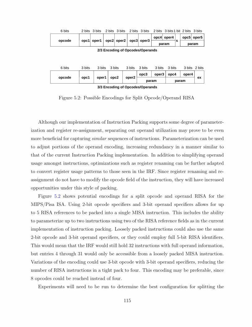
6 bits 3 bits 3 bits 3 bits 3 bits 3 bits 3 bits 3 bits 3 bits 2 bits
opc4 oper4exopc2 oper2oper1opc1opcode
6 bits 1 bit2 bits 3 bits 2 bits 3 bits 2 bits 3 bits 2 bits 3 bits 2 bits 3 bits
opc4 oper4 opc5 oper5
paramparamopcode opc1 oper1 opc2 oper2 opc3 oper3 s
param
opc3 oper3
param
2/3 Encoding of Opcodes/Operands
3/3 Encoding of Opcodes/Operands
Figure 5.2: Possible Encodings for Split Opcode/Operand RISA
Although our implementation of Instruction Packing supports some degree of parameter-
ization and register re-assignment, separating out operand utilization may prove to be even
more beneficial for capturing similar sequences of instructions. Parameterization can be used
to adjust portions of the operand encoding, increasing redundancy in a manner similar to
that of the current Instruction Packing implementation. In addition to simplifying operand
usage amongst instructions, optimizations such as register renaming can be further adapted
to convert register usage patterns to those seen in the IRF. Since register renaming and re-
assignment do not have to modify the opcode field of the instruction, they will have increased
opportunities under this style of packing.
Figure 5.2 shows potential encodings for a split opcode and operand RISA for the
MIPS/Pisa ISA. Using 2-bit opcode specifiers and 3-bit operand specifiers allows for up
to 5 RISA references to be packed into a single MISA instruction. This includes the ability
to parameterize up to two instructions using two of the RISA reference fields as in the current
implementation of instruction packing. Loosely packed instructions could also use the same
2-bit opcode and 3-bit operand specifiers, or they could employ full 5-bit RISA identifiers.
This would mean that the IRF would still hold 32 instructions with full operand information,
but entries 4 through 31 would only be accessible from a loosely packed MISA instruction.
Variations of the encoding could use 3-bit opcode with 3-bit operand specifiers, reducing the
number of RISA instructions in a tight pack to four. This encoding may be preferable, since
8 opcodes could be reached instead of four.
Experiments will need to be run to determine the best configuration for splitting the
115

opcodes and operands. In the most naive implementation, opcodes and operands would be
stored completely independently. More complex variations could use the operand encoding
of 0 to specify the use of default operands for the opcode (e.g. the most frequent instance of
this instruction). Operand encodings 1 through 5 could refer to various other combinations
of registers, while encodings 6 and 7 could specify some of the operands, while leaving one
or more operands to be filled in by a parameter. The availability of additional opcode bits
(from the ex field) may make such a feature less important.
One other interesting feature of the operand parameterization is that not all instructions
use the same operand fields. Thus operand entries in the IRF could contain values for rs, rt,
rd, and the immediate value, letting the corresponding opcode use only the requisite fields
to execute. For example, an add instruction would use rs, rt, and rd, while an ori instruction
would use rs, rt and the immediate value. The IRF operand entry could even support full
32-bit immediate values if experiments show that the extra register width is beneficial.
Opcode and operand splitting is very attractive, since it allows further refinement of the
Instruction Packing formats. The increased ability to parameterize individual components
of a packed MISA instruction is very enticing, considering how other traditional dictionary
compression schemes like DISE have benefited from such flexibility [15].
5.1.3 Packing Instructions with Improved Parameterization
Instruction packing currently allows for the parameterization of immediate values, branch
offsets and register destinations (rd) for R-type instructions. Each of these styles of
parameterization is handled by checking the opcode type of the instruction being accessed.
Non-branch I-type instructions use any corresponding parameter through the IMM to
replace the immediate field of the RISA instruction. Branch instructions automatically
use the associated parameter as a signed 5-bit offset distance for branching. R-type
instructions can only use the matched parameter to replace the 5-bit register destination
field. Although these parameters allow for greater redundancy to be simply captured in an
application, they artificially limit certain similar instruction sequences from being packable.
For instance, incrementing a register by one is a frequently occurring operation, yet the only
parameterizable part of such an instruction is the immediate value. It would be better if we
could actually parameterize the same source and destination register (rt and rs for I-type),
so that they could be replaced when the actual register specified in the IRF is different from
116

6 bits 5 bits 5 bits 5 bits 5 bits6 bits
(rs) 4(R−type) 0 (rd) 4(rt) 6 (func) addu (param) rd/rs
IRF entry #
3
6 bits 5 bits 5 bits 5 bits
4 (I−type) lw
11 bits
(imm) 24 (param) rt(rs) 29 (rt) 5
rsrtrd
immopcode/function code
rd/rs
rs/rtrd/rt
6 bits 5 bits 5 bits 5 bits11 bits
(rs) 295 (I−type) sw (rt) 9 (imm) 32 (param) imm
6 bits 5 bits 5 bits
6 (R−type) 0 (rs) 11 (rt) 15 (rd) 4 (func) subu
5 bits 6 bits
(param) op
3 bits 2 bits
ex
33/x
44/y
5 sw $r9, 32($29)lw $y, 24($29) with $y parameterlw $r5, 24($29)add $x, $x, $r6 with $x parameteradd $r4, $r4, $r6
sw $r9, z($29) with z immediate parametersubu $4, $11, $15newop $4, $11, $15 with R−type newop
5/z6
6/newop
Instructions and parameterizable variants Parameterization Variants (3 bits)
Parameterizable RT Load Word Instruction
Parameterizable RT Load Word Instruction
Parameterizable RD/RS Add Instruction
Parameterizable R−type function code Subtract Instruction
Figure 5.3: Extending RISA Parameterization
the compiler-generated code sequence. These artificial parameterization limitations can be
alleviated by cleverly encoding the packed RISA instruction appropriately.
The RISA currently uses the same instruction formats as the MISA, with some small
restrictions on not placing packed instructions into the IRF. This means that at least 5 bits
of almost every instruction stored in the IRF are ignored, since they refer to a loosely packed
field. We can reduce the size of the instruction registers, or we can make use of these bits to
support larger immediates or for a clever encoding scheme. There are actually eight useful
parameterization combinations, and thus only three bits will be necessary to encode them.
These variants are shown in Figure 5.3. They are rs, rt, rd, rd/rs, rd/rt, rs/rt, imm and
opcode/function code respectively. In the current implementation, we implicitly support
both rd and imm parameterization. The other encodings merely specify which operand or
opcode is to be replaced with the parameter.
117

The specifications for rd/rs, rd/rt, and rs/rt are used when we wish to replace two register
identifiers with the same new register operand. The existing default instruction operands
need not be the same in this case. The most interesting parameterization variant is clearly
the opcode/function code entry. MIPS opcodes are 6 bits in length and R-type function
codes are also 6-bits, so a 5-bit parameter will not be able to completely specify the full
range of available instructions in each type. Instead, one of the two ex bits can be used to
specify the high-order bit of the opcode or function code. This will expose nearly half of all
opcode/function codes for each such parameterizable instruction. This is similar to the split
opcode and operand encoding specified previously in this section. One limitation compared
to the previous split method is that R-type and I-type instructions will not be able to be
parameterized from instructions of a different type (I-type or R-type, respectively).
5.1.4 Packing Instructions at Link-Time
Our current model for Instruction Packing uses profiling and needs to recompile the
application in order to pack instructions effectively. One of the major limitations of compile-
time Instruction Packing is that analysis is limited to the function scope. By moving
to link-time packing, it would be possible to pack instructions based on inter-procedural
analysis information. Similar to the current greedy algorithms for determining instructions
to promote, the application could be scanned for good candidate instructions. These
instructions could then be packed and a measure could be taken of how effective the packing
is. The instruction promotion process would then be guided by attempting to pack the hot
spots in the code. If an instruction in the frequently executed code is not very prominent
statically and does not yield a significant code size savings, then the promotion can be
undone and another candidate instruction can be evaluated. In this way, the promotion and
Instruction Packing operation progresses incrementally towards a compressed executable
with reduced fetch requirements.
Such a system could be implemented on top of existing link-time optimization tools.
Diablo is a retargetable link-time binary rewriting framework that supports ARM, i386,
MIPS, Alpha and IA64 binaries [16]. Diablo can be retargeted to support the ARM/Thumb
or ARM/Thumb2 along with Instruction Packing extensions. This would require a significant
amount of work, considering that the current implementation of Diablo does not even support
ARM/Thumb intermixed code.
118

In addition to providing a single common control flow graph representation for operating
on programs, Diablo also provides optimization routines for eliminating dead code and data,
as well as procedural abstraction [22]. This is an important optimization for embedded
systems, as it can yield significant code compression at minimal cost in execution time.
Instruction packing with an IRF focuses on compressing frequently executed sequences of
instructions, while procedural abstraction works with infrequently executed blocks of code.
We believe that the combination of these two techniques will be favorable, resulting in an
even greater reduction in static code size.
One other limitation on current methods is that library routines cannot be packed, since
they are not recompiled for the packed application. This negatively impacts applications
that depend heavily on library code, since they will only be able to execute a few packed
instructions. With link-time inter-procedural analysis, statically-linked library code could
be packed, leading to improved performance for certain applications. Software windowing
of the IRF would also be improved, since unnecessary saves/restores of IRF entries could be
eliminated due to dynamic instruction promotion.
5.1.5 Instruction Promotion as a Side Effect
Instruction packing use a statically allocated IRF that is set up during application load using
a combination of special promotion instructions. We previously found that dynamically
promoting to the IRF leads to significant levels of overhead due to saving and restoring
instruction registers [31]. This was one reason for moving to hardware register windows to
extend our packing capabilities. The loosely packed format can be modified to provide a
simple channel for promoting instructions to the IRF.
One bit can be reserved from the 5-bit field to indicate reading or writing of the IRF, so
we will be moving to only a 16-entry IRF. When this bit is set to write, an instruction will not
only execute, but also place a copy of itself in the IRF entry specified by the remaining 4-bit
field. When the bit is set to read, then the instruction from the 4-bit field will be executed
on the following cycle, similar to the existing behavior of loosely packed instructions. This
method will allow us to retain some executable loose packs of instructions, instead of having
to use only tight packs for reading and executing from the IRF. We could instead specify
that the 5-bit field is purely used to write into the IRF at the corresponding entry (except
for a non-write at entry 0). This style would require all RISA instructions to be executed
119

via tightly packed instructions.
In order to exploit this type of promotion, instruction registers will require calling
conventions similar to traditional data registers. A subset of registers could be scratch
registers, meaning that they need not be saved before use. They only need to be saved
and restored if there are intervening function calls in the instruction register live range.
Non-scratch registers, on the other hand, would need saving and restoring on function entry
and exit. However, these registers do not need to be preserved across a called function,
thus providing longer-term instruction storage. Although the methods outlined above are
designed to make promotion to the IRF simple and cost-efficient, it is important to note
that instruction register save and restore operations will require additional MISA instruction
executions (as well as additional stack utilization).
The most effective uses for this style of dynamic allocation will be for frequently executed
tight loops in an application. One iteration of the loop can be peeled, placing appropriate
instructions into the IRF entries, and then the remaining loop can be packed tightly using
these newly promoted instructions. This technique can be combined with loop unrolling to
enhance loop performance without serious code growth, since the majority of instructions
would be tightly packed. This feature may be very attractive for the performance-critical
sections of real-time embedded applications that also have to meet code size requirements.
Careful considerations will have to be given in the presence of call instructions and
conditional control flow inside such a loop. Clearly, a call instruction will require the use
of non-scratch instruction registers (or appropriate saves/restores). Conditional control flow
also presents problems, since the peeled instructions may or may not be executed. To handle
this case, any conditional instructions that could be packed will need to be explicitly loaded
into the IRF during the peeled iteration (similar to the current mechanism used to load the
IRF at program start).
Although this promotion technique may not be able to significantly reduce code size, the
improvement in energy savings could be substantial, thus making this an attractive solution
for portable embedded systems. This technique allows the IRF to operate in a manner
similar to the pre-loaded loop cache [26] or zero-overhead loop buffer [20]. The real benefit
is in capturing additional loops that these techniques normally cannot handle, such as loops
with conditional control flow and function calls. Link-time packing could help to eliminate
unnecessary saves and restores based on inter-procedural analysis information. Similarly, we
120

could adapt a rotating register file (like the SPARC) to handle IRF saves and restores on
functions calls and returns.
5.2 Improvements for LIFE
5.2.1 Scaling up Speculation Components
There are a number of different ways that LIFE can be tuned for other fetch stage
configurations. The size of the BP and BTB can be varied. It is likely that LIFE will support
a larger BP and BTB to reduce the number of branch mispredictions while still retaining
energy efficiency since the number of accesses to these larger components are significantly
reduced. It would also be interesting to use a correlating branch predictor with LIFE.
Since the current design of LIFE, when using the NS00 configuration, involves an update to
the metadata in the case of a misprediction, other or even new metadata may be updated
simultaneously without the overhead of the TH-IC access.
5.2.2 Improving Pipeline Decisions
We have limited our changes with LIFE to the fetch stage and data cache portions of
the pipeline. This makes sense for embedded processors since they tend to have simple
pipeline organization after fetch. Since both TH-IC and LIFE have no impact on processor
performance, we predict that their use in high performance, general purpose processors
could yield positive results. Total energy reduction will not be as great as for embedded
architectures since a greater portion of the power budget is used by later (more complex)
pipeline stages, but since any reduction comes without performance penalty, inclusion of
LIFE is still warranted. For these complex pipelines, LIFE can be used to improve resource
scheduling decisions. We already explored a case involving next sequential line prefetch,
showing that LIFE can act as a filter, identifying small loops with repetitive, consistent
execution behavior. The ability to identify repeated instruction sequences very early in
the pipeline can also affect the design of dynamic instruction scheduling, data forwarding,
instruction wakeup logic and other power intensive portions of pipeline execution. New
designs for these structures can exploit the regularity of instruction execution for LIFE-
accessed instructions to reduce power consumption or even to enhance performance since
improved scheduling decisions can be cached in the later pipeline stages for these instructions.
121

Basically, LIFE can be used to identify those phases of program execution that exhibit
very structured, consistent execution patterns. These phases can then be exploited in
various other stages of the pipeline architecture to throttle back resources to reduce power
consumption or to iteratively capture best resource allocation to improve performance (or
both). We believe that the ability to partition the instruction execution into (at least)
two very different execution behaviors opens up new research opportunities in all areas of
processor design.
122

CHAPTER 6
Conclusions
Instruction fetch is a critically important pipeline stage in modern embedded processor
designs. As power and energy become dominant design criteria, we must look to innovative
designs that attempt to reduce the average energy per instruction while still meeting
reasonable performance goals. This dissertation presents two such designs for instruction
fetch engines. The first design is an ISA enhancement that places frequently occurring
instructions into an Instruction Register File for fast, energy-efficient storage that can
be accessed in compressed form. The second design leverages the regularity inherent to
instruction fetch to make future guarantees about fetch behavior, thus allowing the selective
enabling/disabling of individual components in the pipeline.
We have shown that instruction fetch efficiency can be improved by the addition of a small
Instruction Register File that contains the most frequently executed instructions. Fetch
energy is reduced since many instructions can now be accessed via low-power instruction
registers rather than the L1 instruction cache. Code size is reduced due to the ability of
multiple IRF references to be packed together in a single instruction fetched from memory.
Code compression can be very important for embedded architectures, which are often more
tightly constrained than general purpose processors. Even execution time can be slightly
improved through the use of an IRF, since applications may now fit better into cache, and
can recover from branch mispredictions faster. Hardware register windowing allows the IRF
to better handle diverse functions and phase behaviors. Compiler optimizations such as
register re-assignment, instruction selection and instruction scheduling can be adapted to
improve the packing of instructions into registers.
We have shown that a simple direct-mapped L0/filter instruction cache can be replaced
with a Tagless Hit Instruction Cache (TH-IC) that does not require a tag comparison when an
123

instruction can be guaranteed to be in the TH-IC. Additionally, the TH-IC can be bypassed
when a hit is not guaranteed, resulting in the elimination of the L0-IC performance penalty.
We have also shown that the hit rate for a TH-IC is only slightly lower than an L0-IC
of equivalent size due to TH-IC’s ability to capture and exploit the regularity present in
instruction fetch. This results in a technique for instruction cache design that features both
higher performance and greater energy efficiency than the current state of the art in filter
cache design and implementation.
Enhanced analysis of fetch behavior with a TH-IC motivated the need to improve
the efficiency of other fetch components beyond caches as they became the dominant
energy consumers. We then developed the Lookahead Instruction Fetch Engine (LIFE),
a microarchitectural design enhancement that further exploits fetch regularity to better
control access to these power-hungry speculation resources. Using just a few additional bits
per instruction, LIFE eliminates the majority of accesses to the speculative fetch components,
leading to significant reductions in fetch power and total energy consumed. The behaviors
captured by LIFE can also be effectively used to tune other pipeline optimizations as seen
in our case study with next sequential line prefetch. All of this work makes the inclusion
of a small, energy-conscious instruction fetch engine attractive even for high performance
processors.
The fetch energy enhancements that we have developed will clearly impact future pro-
cessor designs. Although the IRF requires additional support through software compilation
tools and ISA changes, designers with the flexibility to construct their ISA from the ground
up will be able to realize significant reductions in energy, code size and even execution time.
The TH-IC and LIFE enhancements are purely microarchitectural in nature, and can thus
be integrated into most existing processor fetch designs. This should increase adoption of
these techniques for existing processor designs that are seeking a boost in energy efficiency,
particularly as designers focus more on energy-efficient and performance-conscious multi-
core architectures. Looking to the future, the presence of hundreds or thousands of cores
on a single die will necessitate the use of enhancements that exploit instruction redundancy
and fetch regularity like IRF, TH-IC and LIFE to minimize the overall energy per executed
instruction without negatively impacting the individual-core performance.
124

REFERENCES
[1] Aragon, J. L., Gonzalez, J., and Gonzalez, A. Power-aware control speculationthrough selective throttling. In Proceedings of the 9th International Symposium on High-Performance Computer Architecture (Washington, DC, USA, 2003), IEEE ComputerSociety, pp. 103–112. 3.7
[2] Araujo, G., Centoducatte, P., and Cortes, M. Code compression based onoperand factorization. In Proceedings of the 31st Annual Symposium on Microarchitec-ture (December 1998), pp. 194–201. 4.2, 5.1.2
[3] Austin, T., Larson, E., and Ernst, D. SimpleScalar: An infrastructure forcomputer system modeling. IEEE Computer 35 (February 2002), 59–67. 2.4, 2.5,3.3
[4] Baniasadi, A., and Moshovos, A. Instruction flow-based front-end throttling forpower-aware high-performance processors. In Proceedings of the 2001 internationalsymposium on Low power electronics and design (New York, NY, USA, 2001), ACMPress, pp. 16–21. 3.7
[5] Bellas, N., Hajj, I., Polychronopoulos, C., and Stamoulis, G. Energy andperformance improvements in a microprocessor design using a loop cache. In Proceedingsof the 1999 International Conference on Computer Design (October 1999), pp. 378–383.3.1, 4.1
[6] Bellas, N. E., Hajj, I. N., and Polychronopoulos, C. D. Using dynamiccache management techniques to reduce energy in general purpose processors. IEEETransactions on Very Large Scale Integrated Systems 8, 6 (2000), 693–708. 3.1, 4.1
[7] Benitez, M. E., and Davidson, J. W. A portable global optimizer and linker.In Proceedings of the SIGPLAN’88 conference on Programming Language Design andImplementation (1988), ACM Press, pp. 329–338. 2.4
[8] Bracy, A., Prahlad, P., and Roth, A. Dataflow mini-graphs: Amplifying super-scalar capacity and bandwidth. In Proceedings of the 37th International Symposium onMicroarchitecture (2004), IEEE Computer Society, pp. 18–29. 4.3
[9] Brooks, D., Tiwari, V., and Martonosi, M. Wattch: A framework forarchitectural-level power analysis and optimizations. In Proceedings of the 27th annualInternational Symposium on Computer Architecture (New York, NY, USA, 2000), ACMPress, pp. 83–94. 2.7.5, 3.3
125
[10] Cheng, A., Tyson, G., and Mudge, T. FITS: Framework-based instruction-settuning synthesis for embedded application specific processors. In Proceedings of the 41stannual conference on Design Automation (New York, NY, USA, 2004), ACM Press,pp. 920–923. 5.1.1
[11] Choi, H., Park, I.-C., Hwang, S. H., and Kyung, C.-M. Synthesis of applicationspecific instructions for embedded DSP software. In Proceedings of the IEEE/ACMInternational Conference on Computer-Aided Design (November 1998), pp. 665–671.4.3
[12] Clark, N., Blome, J., Chu, M., Mahlke, S., Biles, S., and Flautner, K. Anarchitecture framework for transparent instruction set customization in embedded pro-cessors. In Proceedings of the 2005 ACM/IEEE International Symposium on ComputerArchitecture (Washington, DC, USA, 2005), IEEE Computer Society, pp. 272–283. 4.3
[13] Cooper, K., and McIntosh, N. Enhanced code compression for embedded riscprocessors. In Proceedings of the ACM SIGPLAN Conference on Programming LanguageDesign and Implementation (May 1999), pp. 139–149. 4.2
[14] Corliss, M. L., Lewis, E. C., and Roth, A. DISE: A programmable macroengine for customizing applications. In Proceedings of the 30th Annual InternationalSymposium on Computer Architecture (2003), ACM Press, pp. 362–373. 4.2
[15] Corliss, M. L., Lewis, E. C., and Roth, A. A DISE implementation of dynamiccode decompression. In Proceedings of the ACM SIGPLAN Conference on Languages,Compilers, and Tools for Embedded Systems (June 2003), pp. 232–243. 4.2, 5.1.2
[16] De Bus, B., De Sutter, B., Van Put, L., Chanet, D., and De Bosschere,K. Link-time optimization of ARM binaries. In Proceedings of the 2004 ACMSIGPLAN/SIGBED Conference on Languages, Compilers, and Tools for EmbeddedSystems (Washington, DC, USA, July 2004), ACM Press, pp. 211–220. 5.1.4
[17] Debray, S. K., Evans, W., Muth, R., and DeSutter, B. Compiler techniquesfor code compaction. ACM Transactions on Programming Languages and Systems 22,2 (March 2000), 378–415. 4.2
[18] Diefendorff, K., Dubey, P. K., Hochsprung, R., and Scales, H. AltiVecextension to PowerPC accelerates media processing. IEEE Micro 20, 2 (2000), 85–95.4.3
[19] Ernst, D., Hamel, A., and Austin, T. Cyclone: A broadcast-free dynamic in-struction scheduler with selective replay. In Proceedings of the 30th annual InternationalSymposium on Computer Architecture (New York, NY, USA, 2003), ACM, pp. 253–263.3.7
[20] Eyre, J., and Bier, J. DSP processors hit the mainstream. IEEE Computer 31, 8(August 1998), 51–59. 3.1, 4.1, 5.1.5
126
[21] Folegnani, D., and Gonzalez, A. Energy-effective issue logic. In Proceedings ofthe 28th annual International Symposium on Computer architecture (New York, NY,USA, 2001), ACM Press, pp. 230–239. 2.10
[22] Fraser, C. W., Myers, E. W., and Wendt, A. L. Analyzing and compressing as-sembly code. In Proceedings of the SIGPLAN ’84 Symposium on Compiler Construction(June 1984), pp. 117–121. 4.2, 5.1.4
[23] Ghose, K., and Kamble, M. Energy efficient cache organizations for superscalarprocessors. In Power Driven Microarchitecture Workshop, held in conjunction withISCA 98 (June 1998). 3.2.1
[24] Ghose, K., and Kamble, M. B. Reducing power in superscalar processor cachesusing subbanking, multiple line buffers and bit-line segmentation. In Proceedings of the1999 International Symposium on Low Power Electronics and Design (New York, NY,USA, 1999), ACM Press, pp. 70–75. 3.2.1
[25] Gindele, J. Buffer block prefetching method. IBM Tech Disclosure Bulletin 20, 2(July 1977), 696–697. 3.1, 3.7
[26] Gordon-Ross, A., Cotterell, S., and Vahid, F. Tiny instruction caches for lowpower embedded systems. Trans. on Embedded Computing Sys. 2, 4 (2003), 449–481.2.9.1, 4.1, 5.1.5
[27] Guthaus, M. R., Ringenberg, J. S., Ernst, D., Austin, T. M., Mudge,T., and Brown, R. B. MiBench: A free, commercially representative embeddedbenchmark suite. IEEE 4th Annual Workshop on Workload Characterization (December2001). 2.1, 3.4
[28] Hines, S., Green, J., Tyson, G., and Whalley, D. Improving programefficiency by packing instructions into registers. In Proceedings of the 2005 ACM/IEEEInternational Symposium on Computer Architecture (June 2005), IEEE ComputerSociety, pp. 260–271. 1.2, 1, 2, 2.2, 2.6.2, 2.7.2, 2.9.2
[29] Hines, S., Peress, Y., Gavin, P., Whalley, D., and Tyson, G. Guaranteeinginstruction fetch behavior with a lookahead instruction fetch engine (LIFE). Submittedto the ACM/IEEE International Symposium on Microarchitecture, December 2008. 1.3,4, 3
[30] Hines, S., Tyson, G., and Whalley, D. Improving the energy and executionefficiency of a small instruction cache by using an instruction register file. In Proceedingsof the 2nd Watson Conference on Interaction between Architecture, Circuits, andCompilers (September 2005), pp. 160–169. 1.2, 2, 2, 2.7, 2.9.2
[31] Hines, S., Tyson, G., and Whalley, D. Reducing instruction fetch cost by packinginstructions into register windows. In Proceedings of the 38th annual ACM/IEEEInternational Symposium on Microarchitecture (November 2005), IEEE ComputerSociety, pp. 19–29. 1.2, 2, 2, 2.6, 2.6.2, 2.7, 2.7.1, 2.9.1, 5.1.5
127

[32] Hines, S., Tyson, G., and Whalley, D. Addressing instruction fetch bottlenecksby using an instruction register file. In Proceedings of the 2007 ACM SIGPLANconference on Languages, Compilers, and Tools for Embedded Systems (June 2007),pp. 165–174. 1.2, 2, 2, 2.9.2, 2.10
[33] Hines, S., Whalley, D., and Tyson, G. Adapting compilation techniques toenhance the packing of instructions into registers. In Proceedings of the InternationalConference on Compilers, Architecture, and Synthesis for Embedded Systems (October2006), pp. 43–53. 1.2, 2, 2, 2.7
[34] Hines, S., Whalley, D., and Tyson, G. Guaranteeing hits to improve the efficiencyof a small instruction cache. In Proceedings of the 40th annual ACM/IEEE InternationalSymposium on Microarchitecture (December 2007), IEEE Computer Society, pp. 433–444. 1.3, 3, 3, 3.4
[35] Hinton, G., Sager, D., Upton, M., Boggs, D., Carmean, D., Kyker, A.,and Roussel, P. The microarchitecture of the pentium 4 processor. Intel TechnologyJournal (February 2001). 2.1
[36] Hu, Z., Juang, P., Skadron, K., Clark, D., and Martonosi, M. Applyingdecay strategies to branch predictors for leakage energy savings. In Proceedings of theInternational Conference on Computer Design (September 2002), pp. 442–445. 4.1
[37] Inoue, K., Moshnyaga, V., and Murakami, K. Dynamic tag-check omission: Alow power instruction cache architecture exploiting execution footprints. In 2nd In-ternational Workshop on Power-Aware Computing Systems (February 2002), Springer-Verlag, pp. 67–72. 4.1
[38] Inoue, K., Moshnyaga, V. G., and Murakami, K. A history-based I-cachefor low-energy multimedia applications. In Proceedings of the 2002 InternationalSymposium on Low Power Electronics and Design (New York, NY, USA, 2002), ACMPress, pp. 148–153. 4.1
[39] Kim, N. S., Flautner, K., Blaauw, D., and Mudge, T. Drowsy instructioncaches: Leakage power reduction using dynamic voltage scaling and cache sub-bankprediction. In Proceedings of the 35th annual ACM/IEEE International Symposiumon Microarchitecture (Los Alamitos, CA, USA, 2002), IEEE Computer Society Press,pp. 219–230. 3.1
[40] Kin, J., Gupta, M., and Mangione-Smith, W. H. The filter cache: An energyefficient memory structure. In Proceedings of the 1997 International Symposium onMicroarchitecture (1997), pp. 184–193. 1.3, 2.9.2, 3.1, 4.1
[41] Kin, J., Gupta, M., and Mangione-Smith, W. H. Filtering memory referencesto increase energy efficiency. IEEE Transactions on Computers 49, 1 (2000), 1–15. 1.3,3.1, 4.1
[42] Kissell, K. D. MIPS16: High-density MIPS for the embedded market. Tech. rep.,Silicon Graphics MIPS Group, 1997. 4.2
128
[43] Ko, U., Balsara, P. T., and Nanda, A. K. Energy optimization of multilevelcache architectures for RISC and CISC processors. IEEE Transactions on Very LargeScale Integrated Systems 6, 2 (1998), 299–308. 4.1
[44] Krishnaswamy, A., and Gupta, R. Profile guided selection of ARM and Thumbinstructions. In Proceedings of the 2002 ACM SIGPLAN conference on Languages,Compilers and Tools for Embedded Systems (2002), ACM Press, pp. 56–64. 4.2
[45] Krishnaswamy, A., and Gupta, R. Enhancing the performance of 16-bit codeusing augmenting instructions. In Proceedings of the 2003 ACM SIGPLAN conferenceon Languages, Compilers, and Tools for Embedded Systems (2003), ACM Press, pp. 254–264. 4.2
[46] Lau, J., Schoenmackers, S., Sherwood, T., and Calder, B. Reducing codesize with echo instructions. In Proceedings of the 2003 International Conference onCompilers, Architectures and Synthesis for Embedded Systems (2003), ACM Press,pp. 84–94. 4.2
[47] Lee, H.-H. S., Smelyanskiy, M., Tyson, G. S., and Newburn, C. J. Stackvalue file: Custom microarchitecture for the stack. In Proceedings of the 7th Inter-national Symposium on High-Performance Computer Architecture (Washington, DC,USA, 2001), IEEE Computer Society, pp. 5–14. 4.1
[48] Lee, H.-H. S., and Tyson, G. S. Region-based caching: An energy-delay efficientmemory architecture for embedded processors. In Proceedings of the 2000 InternationalConference on Compilers, Architecture, and Synthesis for Embedded Systems (NewYork, NY, USA, 2000), ACM, pp. 120–127. 4.1
[49] Lee, L., Moyer, B., and Arends, J. Instruction fetch energy reduction usingloop caches for embedded applications with small tight loops. In Proceedings of theInternational Symposium on Low Power Electronics and Design (1999), pp. 267–269.2.9.1, 3.1, 4.1
[50] Lee, L., Moyer, B., and Arends, J. Low-cost embedded program loop caching —revisited. Tech. Rep. CSE-TR-411-99, University of Michigan, 1999. 4.1
[51] Lee, R. B. Multimedia extensions for general-purpose processors. In Proceedings ofthe IEEE Workshop on Signal Processing Systems (November 1997), pp. 9–23. 4.3
[52] Lefurgy, C., Bird, P., Chen, I.-C., and Mudge, T. Improving code densityusing compression techniques. In Proceedings of the 1997 International Symposium onMicroarchitecture (December 1997), pp. 194–203. 4.2
[53] Liem, C., May, T., and Paulin, P. Instruction-set matching and selection forDSP and ASIP code generation. In Proceedings of the European Event in ASIC Design(March 1994), pp. 31–37. 4.3
129
[54] Ma, A., Zhang, M., and Asanovic, K. Way memoization to reduce fetch energyin instruction caches. ISCA Workshop on Complexity Effective Design (July 2001). 3.4,4.1
[55] Manne, S., Klauser, A., and Grunwald, D. Pipeline gating: speculation controlfor energy reduction. In Proceedings of the 25th annual International Symposiumon Computer Architecture (Washington, DC, USA, 1998), IEEE Computer Society,pp. 132–141. 3.7
[56] Montanaro, J., Witek, R. T., Anne, K., Black, A. J., Cooper, E. M., Dob-berpuhl, D. W., Donahue, P. M., Eno, J., Hoeppner, G. W., Kruckemyer,D., Lee, T. H., Lin, P. C. M., Madden, L., Murray, D., Pearce, M. H.,Santhanam, S., Snyder, K. J., Stephany, R., and Thierauf, S. C. A 160-mhz, 32-b, 0.5-W CMOS RISC microprocessor. Digital Tech. J. 9, 1 (1997), 49–62. 1.1,2.1, 4.1
[57] Motorola Inc. Wireless engineering bulletin: Introduction to the DSP56300. Tech.rep., Motorola Semiconductor Products Sector, November 1997. 4.3
[58] Padua, D. A., and Wolfe, M. J. Advanced compiler optimizations for supercom-puters. Commun. ACM 29, 12 (1986), 1184–1201. 2.7.3
[59] Pan, H., and Asanovic, K. Heads and Tails: A variable-length instructionformat supporting parallel fetch and decode. In Proceedings of the 2001 InternationalConference on Compilers, Architecture, and Synthesis for Embedded Systems (2001),ACM Press, pp. 168–175. 4.2
[60] Parikh, D., Skadron, K., Zhang, Y., Barcella, M., and Stan, M. Powerissues related to branch prediction. In Proceedings of the International Symposium onHigh Performance Computer Architecture (February 2002), pp. 233–244. 4.1
[61] Patterson, D., and Hennessy, J. Computer Organization and Design, TheHardware/Software Interface. Morgan Kaufmann Inc., 1998. 2.3
[62] Peleg, A., and Weiser, U. MMX technology extension to the Intel architecture.IEEE Micro 16, 4 (1996), 42–50. 4.3
[63] Pering, T., Burd, T., and Brodersen, R. The simulation and evaluation ofdynamic voltage scaling algorithms. In Proceedings of the 1998 International Symposiumon Low Power Electronics and Design (New York, NY, USA, 1998), ACM Press, pp. 76–81. 3.3, 4.1
[64] Phelan, R. Improving ARM code density and performance. Tech. rep., ARM Limited,2003. 4.2, 5.1.1
[65] Reinman, G., Calder, B., and Austin, T. M. High performance and energyefficient serial prefetch architecture. In ISHPC ’02: Proceedings of the 4th InternationalSymposium on High Performance Computing (London, UK, 2002), Springer-Verlag,pp. 146–159. 4.1
130

[66] Savla, V. DSP architectures for system design. Tech. rep., IIT Bombay, November2002. 4.3
[67] Segars, S., Clarke, K., and Goudge, L. Embedded control problems, Thumb,and the ARM7TDMI. IEEE Micro 15, 5 (October 1995), 22–30. 2.7.4, 4.2, 5.1.1
[68] Sherwood, T., Perelman, E., Hamerly, G., and Calder, B. Automaticallycharacterizing large scale program behavior. In Proceedings of the 10th internationalconference on Architectural Support for Programming Languages and Operating Systems(New York, NY, USA, 2002), ACM Press, pp. 45–57. 2.6.1
[69] SimpleScalar-ARM Power Modeling Project. User manual.http://www.eecs.umich.edu/∼panalyzer. 2.5
[70] Smith, A. J. Cache memories. ACM Comput. Surv. 14, 3 (1982), 473–530. 3.1, 3.7
[71] Smith, M., Horowitz, M., and Lam, M. Efficient superscalar performance throughboosting. In Proceedings of the International Conference on Architectural Support forProgramming Languages and Operating Systems (October 1992), pp. 248–259. 2.6.2
[72] Srinivasan, V., Davidson, E. S., and Tyson, G. S. A prefetch taxonomy. IEEETrans. Comput. 53, 2 (2004), 126–140. 3.1, 3.7
[73] Su, C.-L., and Despain, A. M. Cache design trade-offs for power and performanceoptimization: A case study. In Proceedings of the 1995 International Symposium onLow Power Design (New York, NY, USA, 1995), ACM Press, pp. 63–68. 4.1
[74] Tang, W., Gupta, R., and Nicolau, A. Design of a predictive filter cache for energysavings in high performance processor architectures. In Proceedings of the InternationalConference on Computer Design (Los Alamitos, CA, USA, 2001), IEEE ComputerSociety, pp. 68–73. 3.1, 4.1
[75] Tang, W., Veidenbaum, A. V., and Gupta, R. Architectural adaptation forpower and performance. In Proceedings of the 2001 International Conference on ASIC(October 2001), pp. 530–534. 4.1
[76] Warter, N. J., Haab, G. E., Subramanian, K., and Bockhaus, J. W.Enhanced modulo scheduling for loops with conditional branches. In Proceedings of the25th annual international symposium on Microarchitecture (Los Alamitos, CA, USA,1992), IEEE Computer Society Press, pp. 170–179. 2.7.3
[77] Weaver, D., and Germond, T. The SPARC Architecture Manual, 1994. 2.6.2, 2.7.4
[78] Willems, M., Keding, H., Zivojnovic, V., and Meyr, H. Modulo-addressingutilization in automatic software synthesis for digital signal processors. In Proceedingsof the 1997 IEEE International Conference on Acoustics, Speech, and Signal Processing(ICASSP ’97) -Volume 1 (1997), IEEE Computer Society, pp. 687–690. 4.3
131

[79] Wilton, S. J., and Jouppi, N. P. CACTI: An enhanced cache access and cycle timemodel. IEEE Journal of Solid State Circuits 31, 5 (May 1996), 677–688. 2.7.5, 3.3, 3.6
[80] Yang, C., and Orailoglu, A. Power efficient branch prediction through earlyidentification of branch addresses. In Proceedings of the International Conference onCompilers, Architecture, and Synthesis for Embedded Systems (October 2006), pp. 169–178. 4.1
[81] Yang, C.-L., and Lee, C.-H. HotSpot cache: Joint temporal and spatial localityexploitation for I-cache energy reduction. In Proceedings of the 2004 InternationalSymposium on Low Power Electronics and Design (New York, NY, USA, 2004), ACMPress, pp. 114–119. 4.1
132

BIOGRAPHICAL SKETCH
Stephen Roderick Hines
Stephen Roderick Hines was born March 28, 1979 in Staten Island, New York. He attended
Illinois Institute of Technology, graduating with high honors in the Spring of 2001 with a
Bachelor of Science Degree in Computer Engineering. In the Summer of 2004, he graduated
from The Florida State University with a Master of Science Degree in Computer Science
under the advisement of Professor David Whalley. With Professors Gary Tyson and David
Whalley as co-advisors, Stephen completed his Doctor of Philosophy degree in Computer
Science at The Florida State University in the Summer of 2008. Stephen currently resides
with his wife, Kiruthiga, in Northern California, both working towards careers in academia.
His main areas of interest are compilers, computer architecture, and embedded systems.
133