improvements to better · · 2014-10-28such as ericsson .co and by high degree researches in...
TRANSCRIPT
The candidate confirms that the work submitted is their own and the appropriate credit has been given where reference has been made to the work of others. I understand that failure to attribute material which is obtained from another source may be considered as plagiarism. (Signature of student) ___________________
Improvements to Better Handoff Latency in Mobile IP
Amar Adel Khorshid BSc Computer Science
Session (2008/2009)
ii
Summary
As Mobile IP has recently occupying a big gap in the networking filed, where the
concept behind the idea is to maintain the same IP address within multiple networks. The
mobile IP protocol is still under investigation by many telecommunication companies and
researches, in particular the handoff latency generated by the Mobile IP protocol is high and
further suggestions were given by many researches, however optimal level hasn’t yet
achieved.
Overlapping the domains in the mobile IP network has shown faster handoff within
the network. However less throughput and more packets loss average were discovered by
the network during the handoff. It is the intended that this project will look to ascertain why
non-overlapping the domains within the network, can be a suitable solution to the mobile IP
network during the handoff rather than having overlapped domains.

iii
Acknowledgments
First of all, I would like to thank my supervisor Martine Dyer, for his help, supports and
guidance during this project. He was always tracking my progress and informing me with
many advises. I also would like to thank my assessor Jie Xu, who gave me the idea of
including the mathematical analysis which token the project to a more annalistic level.
Thanks must also go to my friends who were supporting me with documents related to the
subject.
A special thanks to my father Adel Khorshid who was always advising me when
things seems to be complicated for me. I also thank him as he offered me with
the opportunity of being a student in the school of computing at Leeds
University.
Finally I’d like to dedicate this project to the memory of Husam Nasher.

iv
List of Acronyms
In this report, the following acronyms are used.
• UDP - User Datagram Protocol
• TCP - Transmission Control Protocol
• FTP - File Transfer Protocol
• IP - Internet Protocol
• IPv4 - Internet Protocol version 4
• MIPv4 - Mobile Internet Protocol version 4
• HA - Home Agent
• MH - Mobile Host
• MN - Mobile Node
• CN - Correspondent Node
• QoS - Quality of Service
• ICMP - Internet Control Message Protocol
• MAC - Media Access Control
• ACK – Acknowledgment
• HMIP - Hierarchal Mobile IP routing Protocol
• RTT - Rounding Trip Time
• RTO - Retransmission Timeout
• BU - Binding Update (message)
v
Contents
1. Introduction & Background Research 1.1. Introduction ...................................................................................................... 1 1.2. Aims.................................................................................................................. 3 1.3. The Objectives................................................................................................... 4 1.4. Minimum Requirements ................................................................................... 4 1.5. Schedule and Report Progress .......................................................................... 5 1.6. Background Research ....................................................................................... 7
1.6.1. Overview .............................................................................................. 7 1.6.2. Mobile IP Architecture ......................................................................... 7
1.6.2.1. Mobile Node ............................................................................. 7 1.6.2.2. Home Agent ..............................................................................7 1.6.2.3. The Foreign Agent ................................................................... 7 1.6.2.4. Correspondent Node ................................................................ 7
1.6.3. Care-of-Address (CoA) ........................................................................ 8 1.6.3.1. Discovering the Care-of-address .............................................. 8 1.6.3.2. Registering the Care-of Address .............................................. 9
1.6.4. Tunnelling .......................................................................................... 10 1.6.5. Micro Mobility ................................................................................... 11 1.6.6. Triangle Routing Problem .................................................................. 11 1.6.7. Route Optimization ............................................................................ 12
2. Topology Design
2.1. Overview ........................................................................................................ 13 2.2. Designing the Topology ................................................................................. 13
2.2.1. Setting the Hierarchical Routing ........................................................ 14 2.2.2. Setting Hierarchal Addresses ............................................................. 15 2.2.3. Create links Between Wired AND Wireless Nodes ........................... 15 2.2.4. Setup TCP Connections Between a Wired Node and The Mobile
Hosts.................................................................................................... 15 2.2.5. Mobile Nodes Movement in the Network .......................................... 16
3. The Overlapped-Domains Model
3.1. Overview ........................................................................................................ 17 3.2. Setting the Optimal Overlapping Area distance ............................................. 18
3.2.1. Throughput Calculation ...................................................................... 18

vi
3.2.2. Packet Loss Calculation ..................................................................... 19 3.2.3. Results and Explanations ................................................................... 19
3.3. 100-Overlapping Analysis Over MN Speeds ................................................. 20 3.3.1. 100-Overlapping Throughput Calculation ......................................... 20
3.3.1.1. Results and Explanations ...................................................... 22 3.3.2. 100-Overlapping Packet Loss Calculation ......................................... 23
3.4. Overlapping Region; Handover and Collision Events Analysis .................... 25 3.4.1. Case (1) .............................................................................................. 26 3.4.2. Case (2) .............................................................................................. 27 3.4.3. Case(3) ............................................................................................... 27 3.4.4. Case(4) ............................................................................................... 28 3.4.5. Case(5) ............................................................................................... 29 3.4.6. Case(6) ............................................................................................... 29
3.5. Collision Proof With NS-2 ............................................................................. 30 3.5.1. The Network Behaviour When W = 3/sec .......................................... 31 3.5.2. The Network Behaviour When W = 20/sec ........................................ 32 3.5.3. Discussion and Further Analysis ........................................................ 33
4. The Non-Overlapped-Domains Model
4.1. Overview ........................................................................................................ 34 4.2. Non-Overlapping Throughput Calculation .................................................... 34
4.2.1. Results and Explanations (1) .............................................................. 35 4.2.2. Results and Explanations (2) .............................................................. 36
4.3. Non-Overlapping Packet Loss Calculation .................................................... 38 4.4. Non-Overlapping Region Analysis ................................................................ 39
4.4.1. Case (1) .............................................................................................. 40 4.4.2. Case (2) .............................................................................................. 41 4.4.3. Case (3) .............................................................................................. 41
5. Delay Time
5.1. Overview ....................................................................................................... 42 5.2. End-To-End Delay In the Overlapping area ................................................. 42 5.3. End-To-End Delay For TCP Connections .................................................... 43
6. Evaluation and Conclusion
6.1. Evaluating the Project Accuracy .................................................................... 45 6.2. Evaluating the Experiments Results .............................................................. 46 6.3. Comparison With Previous Work .................................................................. 49 6.4. Conclusion ..................................................................................................... 51
Student: Amar Adel Khorshid Supervisor: Martin Dyer
1
Section 1 Introduction & Background Research
1.1. Introduction
This document addresses issues regarding Mobile IP and how it can allow users to keep the
same IP address, stay connected, and maintain ongoing applications while roaming between
IP networks, this documentation aims to give a clear description of how Mobile IP was
created to enable users to keep the same IP address while travelling to a different network
without causing the connection to be lost during the handoff procedure.
Handoff in one side is representing the major IP network problem, these is due to the
protocol known as the Mobile IP Protocol (i.e. MIP) designed to proceed such a process,
which conceptually relay on an algorithm called Triangle Routing, where destined packets
take a long path in order to reach their final destination and delay time is increased.
Within Mobile IP network, cells are routing packets to other devices in the network in two
ways either via wired communication or wirelessly. With wireless communication, casting
distance is represented in domains (i.e. zones), thereby each cell has its own casting
domain. Domains with any large network can be designed in one of two model
architectures. The first one intending to overlap domains in the network and called
overlapped-domains model, the second one leaving the network domains independent from
each other, hence called non-overlapped-domains model.
Overlapping the domains has been adopted according to enable fast handoff (i.e. handover),
while on the other hand issues emerged with this concept and reasons behind that left blank
by many researches. One might ask “Would overlapping domains can be developed as to
propose a new handoff schema?”. Others might ask the same question but in different
manner, “What actually cause the high packet loss during the handoff when domains are
overlapped and is there any other model which can be adopted instead?”.

Student: Amar Adel Khorshid Supervisor: Martin Dyer
2
Nevertheless, the inferences resulted by the researches in the telecommunication companies
such as Ericsson .co and by high degree researches in telecommunication engineering and
computer sciences degrees have lead to suspicion arguments and left so many questions
overhead.
During the investigation of the current telecommunication computerised system, I’ve been
informed by people such as the head of engineering department at Orange co. in Uganda
MR. Ezat Radman and the head of the maintenance department in MTN-YEMEN co. MR Hani
Al-Dubai. That, “in terms of loss in the network, non-overlapping domains within the current
2G and 3G networks are performing better than those when domains are overlapped”, but
reasons left blank again!!.
The subject area started to attract my attention and discovering the Mobile IP protocol
scientifically was related to my computer degree. Therefore this project is aiming to tackle
the problem generated in the overlapping area between the network domains, however the
problem has first to be observed. Thereby, research has to be planned with quality, and
investigating the network layer protocols have to be addressed.
Starting with Section (1), the main components of mobile IP networks will be described
along with their purpose and effectiveness in Mobile networks. Diagrams provided in this
documentation have not been copied from an internet resource as I thought it would be
more helpful if I can create my own diagrams after researching information from multiple
resources. Description of the Care-of-address importance is addressed as well as the
operations involved such as Discovering the care-of-address, Registering the Care-of
Address, Secure Mobile IP registration, Automatic home agent discovery and Tunneling
processes with related issues.
Second section will describes how the Topology is built, it will provide some core and
technical information about the topology’s components and how they have been placed in
order to take the final shape of the proposed network. It includes information such as;
Setting the hierarchical routing, creating the topology objects, setting positions for wireless
nodes and creating movements of the Mobile Hosts.

Student: Amar Adel Khorshid Supervisor: Martin Dyer
3
In section (3), the real challenge will be started where technical problems are to be
discovered. In particular, the reason behind the high handoff latency when domains are
overlapped. The Network Simulator NS-2 is the proposed tool to obtain my experiments
along with AWK scripts to be used as an appropriate measurement tools to gather
information generated by NS-2. This section will be divided into three parts; the first part
will test the MIP with different overlapping area distances and chose the best one
accordingly as to be used with the next sections. These will be done in a small network
topology for accuracy purposes.
Part two will contains further experiments as to illustrate the impact of the transmission
quality when the overlapped area between wireless nodes changes in addition to the mobile
nodes speed. These will be tested on a more realistic topology mentioned in section [2].
Part three from section [3] will relay upon a second analysis methodology. Mathematical
analysis will be adopted as to prove the investigated assumptions inherited in part two.
Thereby the problem will be known and further efforts will be planned to produce a solution
to this problems.
Similar to section [3], section [4] will show the proposed solution as to solve or at least to
reduce the high latency and packet loss being disqualifying the MIP network performance
when domains are overlapped. Thus, the non-overlapping-domains model will be adopted
and further observation will be made according to mobile nodes speeds and non-overlapping
area distances. In addition, the solution will be analyzed mathematically in the next part of
this section, whereby comparison between the two models will be easier during the
evaluation part of this project. Section [5], will show the delay time routing in the MIPv4.
Finally, the evaluation part will be documented in section [6]. This section will covers three
evaluations sides as; 1- To evaluate the accuracy of the project, 2- To evaluate the solution
and what are the disadvantages and what can be done in order to give better results within
the MIP network and 3- To evaluate the project according to some other researches papers
available in the literature and what kind of struggles I’ve faced during the project phases.
1.2 Aim
The aim of this project is to evaluate the performance of the Mobile IP network and reduce
the handover latency in the overlapped area between base stations within the network.
Student: Amar Adel Khorshid Supervisor: Martin Dyer
4
1.3 The objectives
The objectives of the project are to:
• Understanding of how the mobile IP protocol works and what other external processes
involved.
• Understand the performance of the Mobile IP network with overlapped areas between
network domains.
• Understand the performances of each possible situation that designed to handle the
handover situation in the Mobile IP network.
• Understand about the network simulations and which simulator application is appropriate
for this Project.
• Understand how to use ns-2 as to build the network and evaluate the performance of the
Mobile IP network in several cases.
• Investigate the reason behind the high handoff latency in the overlapped-domains model.
• Evaluate the new performance of the network according to the overlap and non-overlap
cases.
1.4 Minimum requirements
• Point to the necessarily improvement to reduce the handoff latency.
• Improvement in TCL-C++ based programming skills.
• Develop skills in the network simulation field with ns-2.
• Build a small network to be examined with ns-2 over different scenarios.
The possible extensions are:
• Develop scenarios to be run over different models.
• Develop scenarios with different values for the Mobile node speed and overlapping area
distance and select the best performance between them.
• Build scenarios to reduce the problems obtained in the overlapping area during handoff.
• Point to time delay generated by the routers in the Mobile IP network.
Student: Amar Adel Khorshid Supervisor: Martin Dyer
5
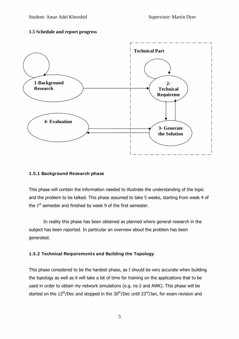
1.5 Schedule and report progress
Technical Part
1.5.1 Background Research phase
This phase will contain the information needed to illustrate the understanding of the topic
and the problem to be talked. This phase assumed to take 5 weeks, starting from week 4 of
the 1st semester and finished by week 9 of the first semester.
In reality this phase has been obtained as planned where general research in the
subject has been reported. In particular an overview about the problem has been
generated.
1.5.2 Technical Requirements and Building the Topology
This phase considered to be the hardest phase, as I should be very accurate when building
the topology as well as it will take a bit of time for training on the applications that to be
used in order to obtain my network simulations (e.g. ns-2 and AWK). This phase will be
started on the 12th/Dec and stopped in the 30th/Dec until 23rd/Jan, for exam revision and
4- Evaluation 3- Generate the Solution
2- Technical
Requireme
1-Background Research
Student: Amar Adel Khorshid Supervisor: Martin Dyer
6
training on the applications. On the 23rd Jan, It will be started again until week 3 of the 2nd
semester.
It is the case that problems within this phase are normally generated. Installation the
NS-2 was the issue, as I had to install it in vista via Cygwin and the lack of libraries in
Cygwin was disabling the smooth following of the intended plan. However the problem has
been overcame with 1 week delay, thereby I finished this phase week 4 of semester 2.
1.5.3 Generate the Solution
In this phase I am assuming to start evaluate the Mobile IP network with various scenarios
and chose the best one. This phase will starts by week 3 of the 2nd semester and completed
by week 7.
This phase has started in week 4 due to a delay happened in the previous phase.
However this phase has accomplished in the assumed period a long with the mathematical
analysis in each of the overlapping and non-overlapping domains models.
1.5.4 Evaluation
This phase will compare the new performance of the MIP network when handover situation
occurred- using the new best chosen model- with the old performance of the MIP network
when Overlap model was used. This phase will be started from week 4 (along with phase 3)
and stopped by week 9; taking into account that time will be short from week 8 because of
the exam revision.
Student: Amar Adel Khorshid Supervisor: Martin Dyer
7
1.6 Background Research
1.6.1 Overview
In this section I am aiming to achieve the first two objectives of this project. This can be
done by investigating the Mobile IP architecture, what are the major ideas behind the
literature and what are the important protocols that been used as-in to maintain the
network operated and acceptable.
1.6.2 Mobile IP architecture
1.6.2.1 Mobile node
Mobile node is a device whose software enables mobility. Mobile IP supports mobility by
binding the home address of the mobile node with its care-of address.[20]
1.6.2.2 Home agent
The Home Agent is a router in the home network of the mobile node, packets are sent from
a Correspondent Node to the Mobile Node, and this procedure is done by establishing a
tunnel between the home agent router and the moving node in a foreign agent.
The home agent support a mobility binding table, the binding table identifies each mobile
node by the home address, temporary care-of address and association lifetime.[11, 20]
1.6.2.3 The Foreign agent
The Foreign Agent is the agent where the mobile node is attached to it when it roams out of
its Home Agent network. The Foreign Agent will be operated as to transfer data packets
from the Home Agent to the Mobile Node after attaching a care-of-address to the mobile
node. This care-of address will be added to the visitor list information table in the foreign
agent and in the binding table in the home agent.[20]
The visitor list in the Foreign Agent identifies each mobile node by the home address,
temporary care-of address, association lifetime and media address.
1.6.2.4 Correspondent node
Student: Amar Adel Khorshid Supervisor: Martin Dyer
8
Foreign network
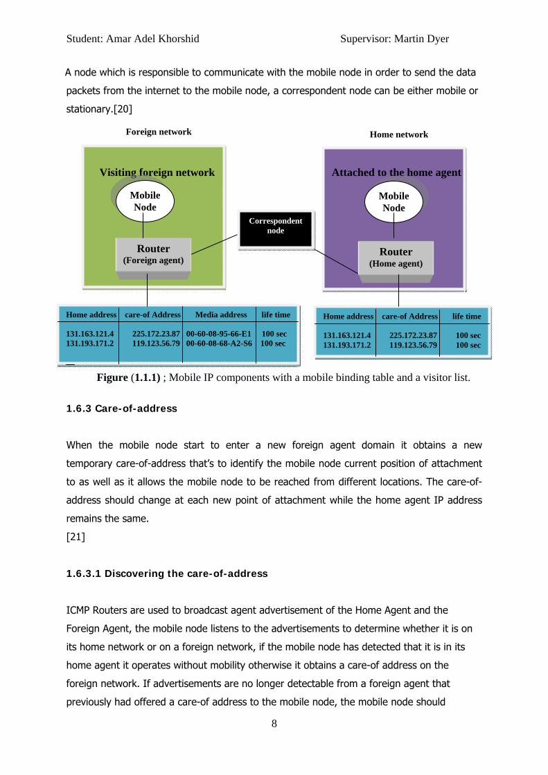
A node which is responsible to communicate with the mobile node in order to send the data
packets from the internet to the mobile node, a correspondent node can be either mobile or
stationary.[20]
Visiting foreign network Attached to the home agent
Figure (1.1.1) ; Mobile IP components with a mobile binding table and a visitor list.
1.6.3 Care-of-address
When the mobile node start to enter a new foreign agent domain it obtains a new
temporary care-of-address that’s to identify the mobile node current position of attachment
to as well as it allows the mobile node to be reached from different locations. The care-of-
address should change at each new point of attachment while the home agent IP address
remains the same.
[21]
1.6.3.1 Discovering the care-of-address
ICMP Routers are used to broadcast agent advertisement of the Home Agent and the
Foreign Agent, the mobile node listens to the advertisements to determine whether it is on
its home network or on a foreign network, if the mobile node has detected that it is in its
home agent it operates without mobility otherwise it obtains a care-of address on the
foreign network. If advertisements are no longer detectable from a foreign agent that
previously had offered a care-of address to the mobile node, the mobile node should
Mobile Node
Router (Foreign agent)
Router (Home agent)
Mobile Node
Home address care-of Address life time 131.163.121.4 225.172.23.87 100 sec 131.193.171.2 119.123.56.79 100 sec
Home network
Home address care-of Address Media address life time 131.163.121.4 225.172.23.87 00-60-08-95-66-E1 100 sec 131.193.171.2 119.123.56.79 00-60-08-68-A2-S6 100 sec
Correspondent node
Student: Amar Adel Khorshid Supervisor: Martin Dyer
9
5- Update Visitor list
Foreign network
1- Send registration request
2- Send registration request
3- Update binding table.
4- Confirm registration
presume that foreign agent is no longer within range of the mobile node's network interface.
In this situation, the mobile node should begin to hunt for a new care-of address, or
possibly use a care-of address known from advertisements it is still receiving. The mobile
node may choose to wait for another advertisement if it has not received any recently
advertised care-of addresses, or it may send an agent solicitation as to inform its presence
to a foreign agent on the foreign network. [21]
1.6.3.2 Registering the Care-of Address
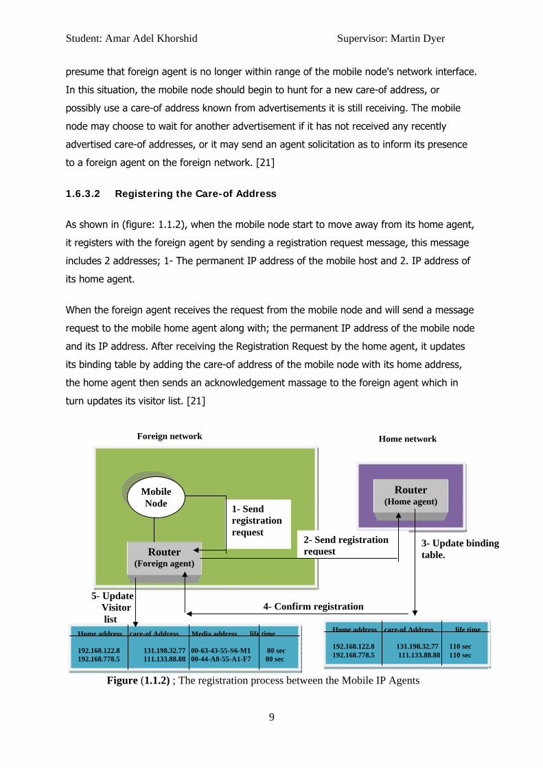
As shown in (figure: 1.1.2), when the mobile node start to move away from its home agent,
it registers with the foreign agent by sending a registration request message, this message
includes 2 addresses; 1- The permanent IP address of the mobile host and 2. IP address of
its home agent.
When the foreign agent receives the request from the mobile node and will send a message
request to the mobile home agent along with; the permanent IP address of the mobile node
and its IP address. After receiving the Registration Request by the home agent, it updates
its binding table by adding the care-of address of the mobile node with its home address,
the home agent then sends an acknowledgement massage to the foreign agent which in
turn updates its visitor list. [21]
Figure (1.1.2) ; The registration process between the Mobile IP Agents
Mobile Node
Router (Foreign agent)
Router (Home agent)
Home address care-of Address life time 192.168.122.8 131.198.32.77 110 sec 192.168.778.5 111.133.88.88 110 sec
Home network
Home address care-of Address Media address life time 192.168.122.8 131.198.32.77 00-63-43-55-S6-M1 80 sec 192.168.778.5 111.133.88.88 00-44-A8-55-A1-F7 80 sec

Student: Amar Adel Khorshid Supervisor: Martin Dyer
10
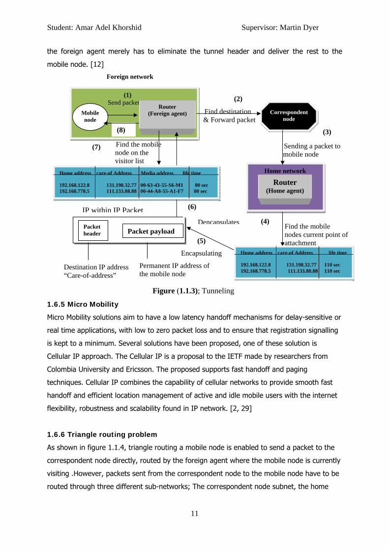
1.6.4 Tunnelling
Process of encapsulating an IP packet within another IP packet in order of routing it to a
location other than the one specified in the original destination field, is called tunnelling.
When the Mobil Node sends a packet while it is operating on a foreign network, the packet
will be destined first to the foreign agent before it reaches the desired destination, where
then the foreign agent will farrowed the packet to the correspondent node.
On the reverse case, where the correspondent node wants to communicate with the mobile
node; the correspondent node will send an IP packet to the permanent IP address of the
mobile node, the mobile’s home agent receives the packet and checks the binding table to
find whether the mobile node is roaming on another foreign agent or at the home agent. If
the mobile agent is on another foreign agent, the home agent will finds out the mobile
node’s care-of address and constructs a new IP header that contains the mobile node’s care-
of address as the destination IP address. The original IP packet is put into the payload of
this IP packet. It then sends the packet. This process of encapsulating one IP packet into
the payload of another is known as IP-within-IP encapsulation, or Tunneling.
When the encapsulated packet reaches the mobile node’s current network, the foreign agent
will encapsulate the packet and finds out the mobile node’s home address stored on the
payload. It then searches into the visitor list to see if it has an entry for that mobile node.
If there is an entry for the mobile node on the visitor list, the foreign agent retrieves the
corresponding media address and relays it to the mobile node. (see Figure: 1.1.3)
The default encapsulation mechanism that must be supported by all mobility agents using
Mobile IP is IP-within-IP.
Using IP-within-IP, the home agent, the tunnel source, inserts a new IP header, or tunnel
header, in front of the IP header of any datagram addressed to the mobile node's home
address. The new tunnel header uses the mobile node's care-of address as the destination
IP address, or tunnel destination. The tunnel source IP address is the home agent, and the
tunnel header uses 4 as the higher level protocol number, indicating that the next protocol
header is again an IP header. In IP-within-IP the entire original IP header is preserved as
the first part of the payload of the tunnel header. Therefore, to recover the original packet,
Student: Amar Adel Khorshid Supervisor: Martin Dyer
11
Find destination & Forward packet
Home network
Sending a packet to mobile node
Find the mobile nodes current point of attachment (5)
(7) Find the mobile node on the visitor list
the foreign agent merely has to eliminate the tunnel header and deliver the rest to the
mobile node. [12]
Foreign network
(2)
Encapsulating
Figure (1.1.3); Tunneling
1.6.5 Micro Mobility
Micro Mobility solutions aim to have a low latency handoff mechanisms for delay-sensitive or
real time applications, with low to zero packet loss and to ensure that registration signalling
is kept to a minimum. Several solutions have been proposed, one of these solution is
Cellular IP approach. The Cellular IP is a proposal to the IETF made by researchers from
Colombia University and Ericsson. The proposed supports fast handoff and paging
techniques. Cellular IP combines the capability of cellular networks to provide smooth fast
handoff and efficient location management of active and idle mobile users with the internet
flexibility, robustness and scalability found in IP network. [2, 29]
1.6.6 Triangle routing problem
As shown in figure 1.1.4, triangle routing a mobile node is enabled to send a packet to the
correspondent node directly, routed by the foreign agent where the mobile node is currently
visiting .However, packets sent from the correspondent node to the mobile node have to be
routed through three different sub-networks; The correspondent node subnet, the home
(1) Send packet
Mobile node
Router (Foreign agent)
Correspondent
node
Router (Home agent)
Packet header Packet payload
Destination IP address “Care-of-address”
Permanent IP address of the mobile node
Dencapsulates
(3)
(4)
(6)
(8)
Home address care-of Address Media address life time 192.168.122.8 131.198.32.77 00-63-43-55-S6-M1 80 sec 192.168.778.5 111.133.88.88 00-44-A8-55-A1-F7 80 sec
Home address care-of Address life time 192.168.122.8 131.198.32.77 110 sec 192.168.778.5 111.133.88.88 110 sec
IP within IP Packet

Student: Amar Adel Khorshid Supervisor: Martin Dyer
12
Home network
Correspondent node network
Correspondent node network
agent’s subnet and the foreign agent where the mobile node is currently visiting. Therefore
packets destined to the mobile node take long path in order to reach their final destination.
Route optimization” has been proposed to address this problem. [3, 16]
Figure (1.1.4); Triangle routing
1.6.7 Route optimization
Route optimization addresses this problem by requiring all hosts to maintain a binding cache
containing the care-of address of mobile nodes. The binding cache is a cache of mobility
bindings of mobile nodes, maintained by a node to be used in Tunneling packets to Mobile
nodes. When sending an IP datagram to a mobile node, if the sender has a binding cache
entry for the destination mobile node, it may tunnel the datagram directly to the care-of
address indicated in the cached mobility binding. In the absence of any binding cache entry,
datagram destined for a mobile node will be routed to the mobile node's home network in
the same way as any other IP datagram -triangle routing.
Route optimization extension to mobile IP includes four messages: binding update, binding
warning, binding request, and binding acknowledgment. [10]
Figure 1.1.5; Routing optimization.
(2. Receive)
(4. Forward packet to mobile node)
Foreign network
Correspondent node
Router (Home agent)
(1.send
(3. Reply back to Mobile
(5. Receive)
Router (Foreign agent)
Mobile node
Binding update
Foreign network
Router (Foreign agent)
Mobile node Binding
acknowledgment
Correspondent node
Student: Amar Adel Khorshid Supervisor: Martin Dyer
13
Section 2
Topology Design
2.1 Overview
In designing the topology to assess the performance of the network in the MIPv4, as to be
used in the next sections when evaluating the network with the overlapped-domains model
and the non-overlapped-domains model. It is necessary to ascertain what research has been
done in this area to not only understand the problem, but to also design suitable
experiments that will build on the existing work. The basic information on how to build a
Mobile IP topology in ns-2 is retrieved by [26].
2.2 Designing the Topology
In this part we regarding to the strategy when design MIP topology that should be followed
as to reflect precise results within the predicate experiments. Hierarchal Mobile IP (HMIP)
topology was adopted relating to the beneficial organised structure it uses in the routing
process. HMIP has been used as the formal design by [6, 2] when discovering the MIP
network behaviour. According to [1], HMIP is the best solution for researches if they are
aiming to result in accurate data generated during the simulation of the network.

Student: Amar Adel Khorshid Supervisor: Martin Dyer
14
Figure (2.1); the topology structure that to be used in this project As it can be seen form figure (2.1), the network contains two wired nodes, three home
agents, three foreign agents and three mobile nodes.
I have tried to avoid placing all the nodes horizontally in order to give it a more realistic
structure.
Note: If all the nodes were placed horizontally the experiment results will be repetitive.
2.2.1 Setting the hierarchical routing
First defining the number of domains, in this scenario it contains 7 domains divided between
nodes as follows;
The first domain contains two wired nodes (0,1,) and they are both placed in separate
clusters which make them two clusters in the same domain, the second domain contains
two nodes (HA,MH) placed in the same cluster, the third domain contains one node (FA) and
obviously it is only placed in one cluster, the fourth domain has the second foreign agent
Second domain
First domain
MH2
0
1
FA HA2
HA
FA1
MH
Third domain
Fourth domain Sixth domain
HA2
MH2
FA
Fifth domain
Seventh domain

Student: Amar Adel Khorshid Supervisor: Martin Dyer
15
(FA1) put in one cluster, as well as the fifth domain which contain the third foreign agent
(FA2) , the sixth domain contains two nodes (HA1,MH1) placed in the same cluster, the
Seventh domain contains two nodes (HA2,MH2) placed in the same cluster. These details
were implemented for both scenarios (overlapping and non-overlapping), however the
distance between the topology domains are different, further sections will show the best
distances chosen.
2.2.2 Setting hierarchal addresses
Hierarchal addresses are divided in three sections the first section indicates the wireless
node, the second section indicates the wired node and the third section indicates the mobile
node. The reader is always advised to look at appendix [B] to be provided with more details.
e.g.:
[ 1 . 0 . 1 ]
2.2.3 Create links between wired AND wireless nodes
The links are used to create physical links between the wired and the agents nodes (home
agents & foreign agents).
A link from the wired node (0) to the wired node (1) is created then a link from the wired
node (1) to each of the home agent and foreign agent nodes is created, the reason is to
create paths between the correspondent node and the agents to allow data flow
transmission.
2.2.4 Setup TCP connections between a wired node and the Mobile Hosts
TCP connections are established between the wired node (0) which, works as a
correspondent node and the three mobile hosts in this scenario.
In the experiments I will observe how packets destined for the mobile hosts are re-directed
by their home agents and from the home agents to the foreign agents using the mobile IP
protocol (triangle routing).
Mobile node Wireless node
Wired node

Student: Amar Adel Khorshid Supervisor: Martin Dyer
16
2.2.5 Mobile Nodes Movement in the network
To enhance best results I have tested the MIP network in different situations as follows;
• MH moving from their HA to next FA(s) and return back to their HA
• MH visiting only one FA and MH1 & MH2 visiting more
• In overlapping area between FA1 and FA2, MH1 and MH2 will obtain handoff in the
same time, this as to evaluate the time delay generated in this case.
• The simulation over, when all MHs are reaching back their HAs. Therefore simulation
time will be various according to the MHs speeds.
These as a result will test the network handoff in many cases such as HA-FA handoff, FA-FA
handoff and vies-versa, which in turn will give an insight of network simulations to those in
real word, because in reality MHs are moving in different manners.
Student: Amar Adel Khorshid Supervisor: Martin Dyer
17
Section 3
The Overlapped-Domains Model;
Technical and Mathematical Analysis
3.1 Overview
This section will provide technical details to show the high handoff latency performed within
the overlapping area. In more details experiments in this section will detect the handoff
performance according to two factors, the MNs movement speeds and the overlapping area
distances. NS-2 will be used to obtain the experiments using the topology designed and
explained in section [2] of the project.

Student: Amar Adel Khorshid Supervisor: Martin Dyer
18
0
500
1000
1500
2000
2500
3000
3500
4000
4500
50 m 70 m 100 m 120 m 170 m
Throughputs
Throughputs
3.2 Setting the optimal overlapping area distance
As to achieve accurate results when testing the mobile IP network, I’ve run the topology
with different overlapping area distances, and accordingly choosing the best performance
recorded. These as a result will enable me to base the next experiments upon the best
performance average that the MIP with inter-domain (overlapping) cells can achieve. The
network performance will be monitored according to the throughput values and the packet
loss average during the experiments. Simple topology will be used as to enhance accurate
size for the overlapping area. The topology can be seen in appendix [B].
3.2.1 Throughput calculation
The throughput was calculated with 30 m/s for the MN movement speed, the MN will start
moving from its HA after 4 seconds with 512 KB as a static packet size and 128 KB as a
maximum packet rate. As it can be shown from figure (3.1) the network throughput average
is 895.06KB when the overlapping area distance is 50 m, and 1172.56KB with 70 meter
overlapping area, resulting in a difference of 277.59KB as to be lost. The network will reach
its maximum throughput when the overlapping area distance is 100 meter with 3826.89KB
as the throughput value pointing to more than 70% of throughput increasing compared to
the throughput generated 70 meter overlapping area. With an overlapping area distance of
more than 100 meter the throughput will start to be decreased resulting on 38% and 78%
decrease when overlapping area distance is 120 and 170 respectively.
Figure (3.1); Shows the MIP throughput in KB according to multiple overlapping area
distances in meter

Student: Amar Adel Khorshid Supervisor: Martin Dyer
19
0.00%
1.00%
2.00%
3.00%
4.00%
5.00%
6.00%
50 m 70 m 100 m 120 m 170 m
Packets loss percentage
Packets loss percentage
3.2.2 Packet Loss calculation
Figure(3.2) illustrate the packets lost during the simulation.
As it can be notice the same conclusion is repeated, where packet loss percentage
is reaching its minimum value of 1.61% when the overlapping area distance is set
to 100 meter and more packets are dropped otherwise.
3.2.3 Results explanation
When the MN is starting to send a UDP request as to be attached with new domain, packets
will be sent to CN and wait until replay message is received, in order to achieve that, MN will
need to send the request while it’s in the overlapping area and not beyond the overlapping
area boundary as mentioned by [5, 6, 12, 15, 25, 31]. Additionally, tunnelling process will
continue its progress until MN starts receiving the first package from the new point of
attachment. However before doing so, the MN will need to acquire new IP address, i.e.
encapsulate its original IP address with a new COA, where on the other hand binding and
updating messages have to be received by the HA and the new FA before the MN gets out
of overlapping area to enhance fast handoff with less handoff latency as mentioned by [5,
25].
Student: Amar Adel Khorshid Supervisor: Martin Dyer
20
Therefore when the overlapping area is small more packets are elected to be lost. This is
because with UDP there will be no grantee of such a packet to be successfully delivered to
the proposed node, these however will yield in more UDP packets to be dropped. As well as
TCP packets are to be lost when the new FA is starting to send packets to the MN while MN
is not yet finalized the handoff process, producing a decrease in the network throughput,
such as in the case of 50m overlapping when compared to the 100m overlapping area
distances.
On the other side of the experiments, packets loss is increasing and throughput is
decreasing when the overlapping area distance is set to value more 100m. This case is
generated due to dual-coverage situation, where MN is still roaming in the overlapping area
between two agents, and CN will keep sending data to the MN in its previous agent where
the previous agent has no media connection to such a MN and therefore packets are
dropped and collided. Similar results have obtained in [14].
To conclude, 100-m for overlapping area distance is yielding in an efficient
performance when compared to the other scales and therefore are elected to be used.
3.3 100-Overlapping analysis over MN speeds
As it has been mentioned, 100 meter to be the distance for the overlapping area will reflect
the best performance that can be achieved by the network. Using a more realistic topology
(the topology in section [2]), this section will analysis the Mobile-IP network when 100-
overlapping area model is adopted. Mainly this section should evaluate the fact of having
multiple speeds to be under taken by the Mobile Nodes. Seven speeds will be given for the
Mobile Nodes which are 10 meter/Sec, 20 meter/Sec, 30 meter/Sec, 50 meter/Sec, 60
meter/Sec, 100 meter/Sec and 150 metre/Sec.
3.3.1 100-Overlapping throughput Calculation
Packet size is (512 Kbps), packets rate is (128 Kbps), the overlapping distance between all
nodes is set to 100 meters and TCP-based FTP connection is enabled to all the mobile hosts
in the following scenarios.

Student: Amar Adel Khorshid Supervisor: Martin Dyer
21
As it can be seen from figure (3.3) and table (3.1), in this experiment the throughput
rate is reduced as the mobile hosts (MHs) increase the speed of their movements. This is
because the mobile hosts will experience higher handover latency due to MHs having less
time to prepare for the handovers. Therefore, there is a higher possibility that the packets
are forwarded to the outdated path and are lost.
Figure (3.3); these figure summaries 7-experiments done by NS-2 to test the MIP network
throughput according to 7-various MHs speeds.
Table(3.1); Throughput results in MB
05
101520253035
10 (m/s) 20 (m/s) 30 (m/s) 50 (m/s) 60 (m/s) 100 (m/s) 150 (m/s)
Throughput Calculation Vs. MHs Speeds
Throughput
MH Speed Throughput(MB) 10 29.9732 20 14.4717 30 6.10617 50 4.51353 60 3.63719 100 1.65873 150 1.33322
Student
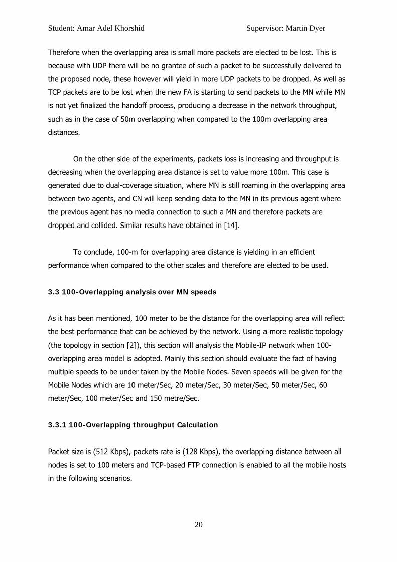
3.3.1.1
Fi
Fig
As it ca
network
t: Amar Ade
1 Results a
gure (3.4)
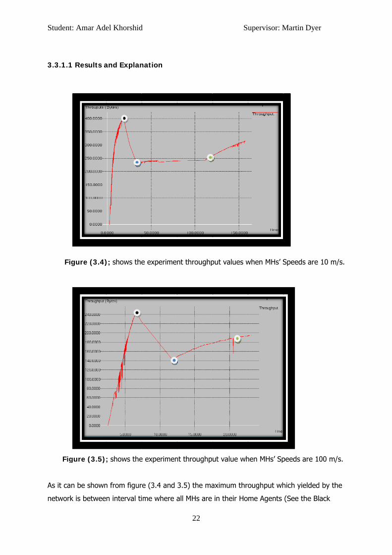
gure (3.5);
n be shown
k is betwee
el Khorshid
and Explan
); shows the
; shows the
n from figur
n interval ti
d
nation
e experimen
e experimen
re (3.4 and
ime where a
22
nt throughp
nt throughp
3.5) the ma
all MHs are
Su
put values w
ut value wh
aximum thro
in their Ho
upervisor: M
when MHs’ S
hen MHs’ Sp
oughput wh
me Agents
Martin Dyer
Speeds are
peeds are 1
hich yielded
(See the Bl
r
10 m/s.
00 m/s.
d by the
ack
Student: Amar Adel Khorshid Supervisor: Martin Dyer
23
points in the graphs), then it starts to decrease until it reach the minimum value when MHs
are starting to move away from their Home Agents (See the Blue points in the graphs). The
green points illustrate the time when the MHs’ are starting to get back to their Home
Agents, these was concluded by running the experiments in the .nam files generated by ns-
2 during the simulations.
The sharp shrink in throughput actually resulted due to the fact where all the mobile
hosts are roaming in the HA&FA-overlapping area, which means that HA-FA handoff is
taking place at this time. HA-FA handoff will precisely acquire higher handoff latency in an
overlapping case when compared with the FA-FA handoff [1]. These in a point of fact will be
generated as the MHs in the case of HA-FA handoff will send BU (Binding Update message)
to the HA directly, where MH will need to send the BU to the CN in the case of otherwise as
addressed in [1, 19].
Therefore higher latency in the case of HA-FA handoff will result in less throughput value,
i.e. the Mobile IP protocol will only offer 2-way handshake communications (MH-HA and MH-
CN-FA), when such a handoff accrue [1], whereby the MH is facing HA-FA handoff this will
result in less data throughput. As well as when the MH is roaming inside its HA, the
communication between the MH and its HA will discard the need of MH-CN communication.
Where it’s necessary when the MHs in not in their HA, resulting in more stoical delay and
dropped packets, therefore less throughput within the network is highly possible.
On the other hand, the movement speed of the MHs will gradually decrease the
throughput pointer as time allocated to achieve the HA-FA handoff will not be enough when
the MH speed is high, as well as less TCP packets will be sent and not equally received due
to less time by the MHs to receive packets from a single agent. These can be shown by
table (3.1). The maxima throughput reached by the network was when the MH speed is
10m/s and the minimum was when the Mobile speed is 105 m/s, this fact was also been
observed by [6, 14]. In fact these only shows us half of the picture and leading to the
question of “Would this affect the amount of data-packets to be lost?”.
3.3.2 100-Overlapping Packet Loss Calculation
The experiments here will illustrate the average of dropped data per second (Kbps) against
multiple MHs’ speeds.

Student
so as th
when M
overlap
probabi
generat
hand, m
This is b
base sta
MH has
major ty
1- Drop
2- Data
proc
same
secti
t: Amar Ade
Figure(3
In this scen
he MHs incr
MHs are in t
ping area c
ility.
As it can be
ted when th
more than 2
because, as
ation (FA) t
s actually sta
ypes of dat
pping all the
a collision w
ess which
e MH, furth
on.
el Khorshid
3.6); shows
nario packet
rease the sp
he overlapp
causes great
e shown fro
he MHs’ spe
29 kbps is b
s the MHs s
to forwarded
arted to rec
a loss,
e data which
which occur
cause the
her details a
d
s the Kbps t
ts are sent
peed of thei
ped area -10
t quality de
om the bar g
eed is 10m/s
eing lost du
tart to obta
d the remai
ceived pack
h still reside
rs in the ca
old and the
about the c
24
that to be d
from the HA
r movemen
00m- where
gradation d
graph in fig
s giving onl
uring the sim
ain such a h
ining data t
kets from th
ed by the ol
ase of over
e new stat
collision eve
Su
ropped aga
A or the cor
nts more pa
e additional
due to an in
ure (3.6) ne
ly 1.325 Kb
mulation wh
andoff, less
to the next
e new statio
ld station d
rlapping du
ions to sen
ent will be g
upervisor: M
ainst the MH
rrespondent
ckets are d
interferenc
crease in pa
early smoot
ps to be los
hen MHs’ sp
s time will b
station whe
on, consequ
ue to data p
uo to delay
nd data sim
given in the
Martin Dyer
Hs speeds.
t node to th
ropped part
ce within th
acket error
th handoff h
st. On the o
peeds are 1
be given to
ere in that t
uential in tw
path update
y in routing
multaneously
e next parts
r
he MHs,
ticularly
e
has
other
05 m/s.
the
time the
wo main
e,
update
y to the
s of this
Student: Amar Adel Khorshid Supervisor: Martin Dyer
25
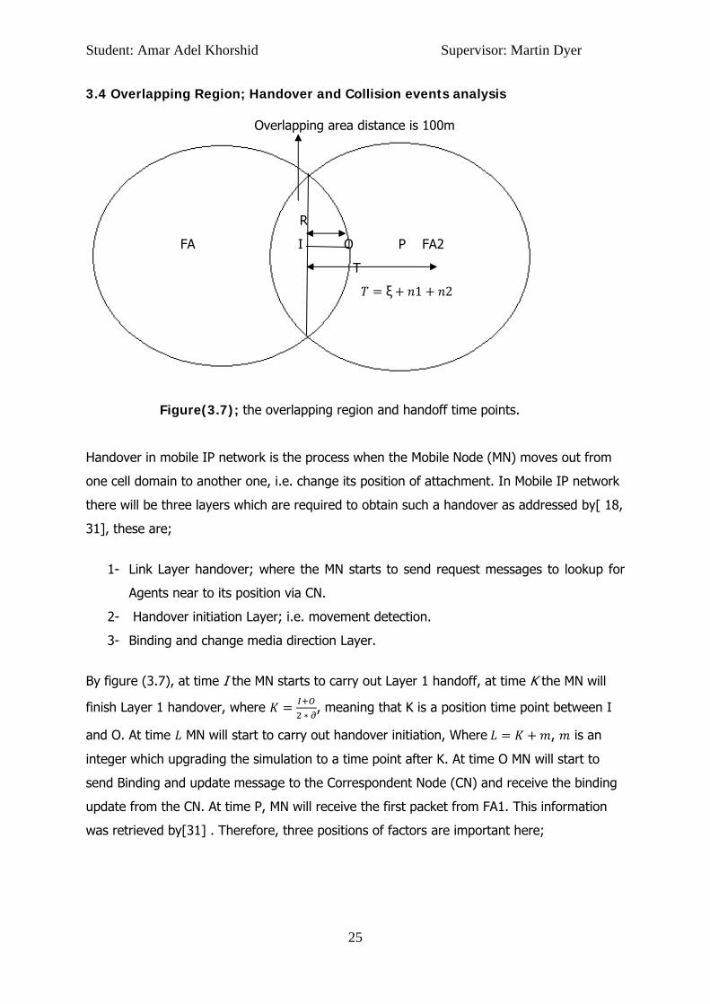
3.4 Overlapping Region; Handover and Collision events analysis Overlapping area distance is 100m
R
FA I O P FA2
T
ξ 1 2
Figure(3.7); the overlapping region and handoff time points.
Handover in mobile IP network is the process when the Mobile Node (MN) moves out from
one cell domain to another one, i.e. change its position of attachment. In Mobile IP network
there will be three layers which are required to obtain such a handover as addressed by[ 18,
31], these are;
1- Link Layer handover; where the MN starts to send request messages to lookup for
Agents near to its position via CN.
2- Handover initiation Layer; i.e. movement detection.
3- Binding and change media direction Layer.
By figure (3.7), at time I the MN starts to carry out Layer 1 handoff, at time K the MN will
finish Layer 1 handover, where
, meaning that K is a position time point between I
and O. At time MN will start to carry out handover initiation, Where , is an
integer which upgrading the simulation to a time point after K. At time O MN will start to
send Binding and update message to the Correspondent Node (CN) and receive the binding
update from the CN. At time P, MN will receive the first packet from FA1. This information
was retrieved by[31] . Therefore, three positions of factors are important here;
Student: Amar Adel Khorshid Supervisor: Martin Dyer
26
1- The interval time that MN takes to starts caring out Layer 1 handover to the time
where MN will starts to send binding update message, we donate this by ξ. That is
ξ .
2- The time that MN takes to send the data to CN (the one-way delay time), we donate
this by 1.
3- The time that MN takes to receive the data from CN, we donate this by 2.
Now let fξ(x), fn1(y), fn2(z) represent the probability density function of ξ, n1 and n2. And let
ξ,n1,n2 , , represent their joint probability density function.
Thus, we have ξ 1 2, we can see that most of the handover layers have been
carried out in K at R, where R is called the radius of overlap region [18, 31]. Moreover, we
already know that the packet loss is increasing gradually according to the MN speed, so we
donate V as the movement direction and speed of MN, that is .
Now, let 1 donate the interval time when the MN start caring layer 1 handover to the time
when MN is in O, and S2 represent the interval time when MN caring out layer 1 handover
to the time when MN receives all the resides packets held on FA (if any). Hence;
1 , . 1 2 , where 1.
By the definition of , 1 2 we actually resulting in the following six cases:
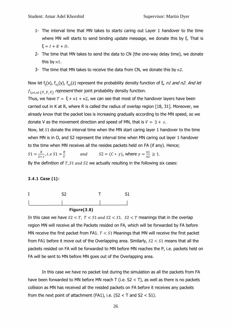
3.4.1 Case (1):
I S2 T S1
Figure(3.8)
In this case we have 2 , 1 2 1. 2 meanings that in the overlap
region MN will receive all the Packets resided on FA, which will be forwarded by FA before
MN receive the first packet from FA1. 1 Meanings that MN will receive the first packet
from FA1 before it move out of the Overlapping area. Similarly, 2 1 means that all the
packets resided on FA will be forwarded to MN before MN reaches the P, i.e. packets held on
FA will be sent to MN before MN goes out of the Overlapping area.
In this case we have no packet lost during the simulation as all the packets from FA
have been forwarded to MN before MN reach T (i.e. S2 < T), as well as there is no packets
collision as MN has received all the resided packets on FA before it receives any packets
from the next point of attachment (FA1), i.e. (S2 < T and S2 < S1).

Student: Amar Adel Khorshid Supervisor: Martin Dyer
27
Therefore, as
probability of PacketLoss at time
P packetNotForwarded P Time where PacketCollided ;
.
3.4.2 Case (2):
I T S2 S1
Figure(3.9)
In this case we have 2, 1 2 1. 2 Meanings that MN will start
receiving packets from FA1 before receiving all the packets resided on FA if any. Similarly as
case (1), 1 Meanings that MN will receive the first packet from FA1 before it move out
of the Overlapping area. 1 2 (Same as case (1)).
Therefore we have the probability value of Zero for 1 1 2 as S1 > T > S2,
however > 0, i.e. there is probability of packets collision event as S2 > T.
Therefore packet loss probability duration is;
P( ) = , where P( ) . (1)
Equation(1) above saying that; in a time point K after the point time T, packets depending
on the MH speed and the overlapping area size are to be under the probability of collision
event. The W variable will be discussed in further parts of this section.
3.4.3 Case (3):
I T S1 S2
Figure(3.10)
In this case we have 1, 2 1 2. Here we have the same situations as
case (2) except for 1 2, which means that while MH is out of the overlapping are

Student: Amar Adel Khorshid Supervisor: Martin Dyer
28
between FA and FA1, there will be sort of packets that are resided on FA and not yet
forwarded. Packet loss in this case is high according to the number of packets that
belonging to MN held in FA, where In fact the resided packets will all be dropped because of
the basic Mobile IP architecture design, where there isn’t buffer and forwarded strategy as
mentioned by [31]. As well as there will be probability for packets to be collide as
2 1 . Therefore packet loss is:
P( ) = , where P( )
(2)
where is the Prps (packet rate/sec) , 3 is the velocity of MN to receive data packets from
FA and H1 is the number of packets resided in FA that have to be sent to MN. Case (3) is an
example of having a small overlap area.
In equation(2), part one of the formula saying that in a time between T and S2, before S1
packets are threatened to be collided after the point time K. The second part is showing the
calculation of the dropped packets caused by the failure of forwarding the resided packets
by the previous agent. The W variable will be discussed in further parts of this section.
3.4.4 Case (4):
I S2 S1 T
Figure(3.11)
In this case we have 2 , 1 1 2. Here we have a new case where 1
meaning that MN will start receiving the first packet from FA1 when it is actually out of
overlapping area region.
Packet loss in this case is zero, because packets resided in FA will be forwarded
before MN reaches O (i.e. before MN is out of the overlapping area) as S2 < S1, thus no
resided packets loss from FA to MN, as well as there will be no packets collision as S2 < T.

Student: Amar Adel Khorshid Supervisor: Martin Dyer
29
Therefore the overlapping area packet loss in this case is zero, i.e. P( ) = 0. Case
(4) is a simple example of having an optimal non-overlapping area network, besides I > S2
in the optimal non-overlapping domains design, see non-overlapped-domains model section.
3.4.5 Case (5):
I S1 S2 T
Figure(3.12)
In this case we have 1 2, 2 1 , as can be notice here we have the new
cases where S1,S2 < T and S1 < S2 at the same time, which means that when MN is in P
(out of the overlapping area) some resided packets on FA still haven’t yet forwarded. Packet
loss in this case is extremely depending on the number of packets that have not been
forwarded from FA. However packets collision is rear in this case, where S2 < T and some of
H1 is already been dropped before receiving any packets from new point of attachment
(FA1). Therefore packets loss is:
, (3)
Equation(3), showing the calculation of the dropped packets caused by the failure of
forwarding the resided packets by the previous agent.
3.4.6 Case (6):
I S1 T S2
Figure (3.13)
In this case we have 1 , 2 2 1. It is noticeable that for the first time we
have S2 < T and S2 > T at the same time. This case is very similar to case (5) where some
resided packets on FA (if any) haven’t yet been forwarded to MN, however in case (6). More

Student: Amar Adel Khorshid Supervisor: Martin Dyer
30
packets are to be dropped regarding the large time acquiring by the network to be
forwarded the resided packets from FA.
From figure (3.13) we can notice that S1 < T, which we can infer that MN will start
receiving packets after it moves out from the overlapping region. Therefore packet loss is
actually depending on the number of resided packets still not yet forwarded, where MN start
to roaming out from the overlapping area, therefore packet loss is equal to:
, (4)
3.5 Collision proof with NS-2
This section will provide technical and mathematical analysis to present deeply the problem
of data collision within the overlapping area and to show why non-overlapping model can be
a better case in this sense.
As it can be shown from table (3.2) below, that the simulation is consisting of 1 HA,
this contains one wireless node (MN) and 2 Foreign Agents (FA + FA1). The simulation will
be run at a MN speed of 30 m/s with direct movements between the agents in the network.
The cast distance of each agent (i.e. domain range) is 240m as it has been set by default in
ns-2. 100m is the range distance of the overlap area between the agents. At 4/sec the MN
will start moving between agents, and TCP connections is enabled.
The purpose of this simulation is to test the behaviour of the MIP network in the
overlapping area. In particular, to discover the point where collision event occurs and cause
the packets to be dropped during the handoff.
MN Speed 30 (m/s)
Number of wireless nodes 1 (MN)
Number of Agents 3 (HA + FA + FA1)
Cast distance 240m (set by default in NS-2 ) Overlapping distance 100m
Direction movement Direct movement
Time spent in the overlapping area 0 sec, 3sec, 13sec, 16sec and 20sec
Transport Layer Protocol TCP
Table (3.2); the simulation parameters used during these experiments

Student
Figure
overlap
This sim
area be
increasi
When t
average
received
the ove
3.5.1 T
Figure
t: Amar Ade
(3.14); pa
ping area
mulation tes
etween FA a
ing gradual
he MN just
e is approxi
d during the
erlapping are
The behavi
e (3.15); the
el Khorshid
acket loss p
sts the beha
and FA1. As
ly according
passing the
mately 1.46
e simulation
ea resulting
iour of the
packet loss ca
d
ercentage a
aviour of the
s it can be s
g to the tim
e overlappin
6% , where
n when MN
g in 94 drop
e network
alculation in th
31
according to
e MIP netw
shown from
me that MN s
ng area betw
on the oth
spend a tim
pped packet
when W =
he experiment
Su
o the stayin
work when M
the figure (
spends in th
ween I and
er hand 36
me of (K +
ts (i.e. %2.5
= 3/sec
where MN in
upervisor: M
ng time of M
MN stays in
(3.14) that
he overlapp
O the tota
17 from 37
20)/sec (i.e
53) overall.
the overlappi
Martin Dyer
MN in the
the overlap
Packets los
ping area (K
l packets lo
11 packets
e. w = 20/se
ng area for 3/
r
pping
ss is
K + w).
oss
have
ec) in
/sec

Student
This gra
collision
the MN
K will be
interval
dropped
start to
3.5.2 T
Figure
Similarly
time be
the prev
and not
packets
yielding
investig
t: Amar Ade
aph (figure:
n with other
is going to
e reached b
time from
d increasing
send reque
The behavi
(3.16); T
y, MN will r
etween 17.6
vious exper
t moving, m
s in the prev
g on 90% pa
Furthermor
gated that a
el Khorshid
: 3.15) illust
r packets fro
move from
by MH in se
17.6 to 20.
gly after sec
est message
iour of the
The packet loss
reach K at s
6 and 37.6.
riment show
more than 18
vious exper
acket loss,
re, from the
at time 25, M
d
trates the p
om FA1. At
m FA to FA1
econd 17.6 a
6. Accordin
cond 17, thi
es to be att
e network
s calculation in
second 17.6
However, d
wn in figure
8 packets h
iment when
increasing i
e trace (.tr)
MN was tryi
32
packets drop
second 10.
until it reac
and stays in
g to the fig
is is becaus
tached with
when W =
n the experim
6 and stays
dropped pac
(3.15). At t
have droppe
n MN stays
in this posit
file generat
ing to receiv
Su
pped in the
.6 from the
ch the overl
n K for 3 sec
ure(3.15) a
se Layer 2 h
the new po
= 20/sec
ent where MN
there for 20
ckets have l
time 25/sec
ed where it
for only 3/s
tion area du
ted by ns-2
ve its care o
upervisor: M
overlapping
start time o
lapping area
c, hence W
above, pack
handoff has
oint of attac
N in the overla
0sec, hence
largely incre
c where MN
was less th
sec in the ov
ue to packet
2 during the
of address r
Martin Dyer
g area beca
of the simu
a at second
in this case
kets start to
accrued an
chment.
apping area fo
e W is the in
eased comp
N is actually
an 10 drop
verlap area
ts collision.
e simulation,
registration
r
ause of
lation
d 15.
e is the
be
nd MN is
r 20/sec
nterval
pared to
in K
ped
,
, I’ve

Student: Amar Adel Khorshid Supervisor: Martin Dyer
33
request, however receiving the replay message failed at that time due to packets collision
occurrence, and further replay packet contains the COA is been send in latter time. In
25.9/sec to time 30.0 dropped packets has decreased to a constant level, this in fact support
the behaviour addressed in [27, 31], where sending/receiving processes are constant but
facing high handoff latency until MN finishing the registration processes with FA1.
3.5.3 Discussion and further analysis
ξ,n1,n2 , ,
Figure (3.17)
As been mentioned previously Case (2) and Case (3) are the situations which affected by
packets collision, therefore it is worthwhile to be mentioned here. According to equation 2
and 3, in particular the part is representing the interval time of the
probability number of collided packets in the overlapping area, here K is a time point where
collision is starting to occurs, in this case we have , that mean collision will take place
after FA1 starts to send data to MN, plus the interval time between S2 and S1, where any
packets exceeding this interval time point will be dropped as registration process has
finished, and Layer 3 handoff has already taken place in the network. Therefore FA has
updated its binding table resulting on a non-accessibility of any connection media with MN.
Figure (3.17) shows the function that represent the relation between the percentage
packet loss function with value of - that MN will stays after it reach . Therefore for
accuracy, the value of has to be taken into account and added to equation 2 and 3. Thus
we had w in; for case 2 and
for case 3.

Student: Amar Adel Khorshid Supervisor: Martin Dyer
34
Section 4 Non-Overlapped-Domains Model; Technical and Mathematical Analysis
4.1 Overview
In the non-overlapping area the mobile nodes will only obtain such a handoff when they
start to go beyond the current agent domain, where no 801.11 wireless communication is
shared by the current and the new agent as being addressed by[23, 28].
This section will represent the second part of the project. The non-overlap model will
be adopted to evaluate the Mobile IP Network. The same network characters will be used as
when used to evaluate the Mobile IP network with the overlapped model. This is because to
reach the conclusion of which model is representing the best performance. Thereby,
throughput and packet loss will be calculated over multiple speeds for the Mobile Nodes.
4.2 Non-Overlapping Throughput Calculation
In this experiment the throughput rate is gradually reduced as the mobile hosts increase
the speed of their movements. The distance between the domains are set to 58m, so when
mobile node moves faster more packets are lost particularly when handover occurs.
Student: Amar Adel Khorshid Supervisor: Martin Dyer
35
0
10
20
30
40
50
60
10 (m/s) 20 (m/s) 30 (m/s) 50 (m/s) 60 (m/s) 100 (m/s) 150 (m/s)
Calculating theThroughput
Throughput
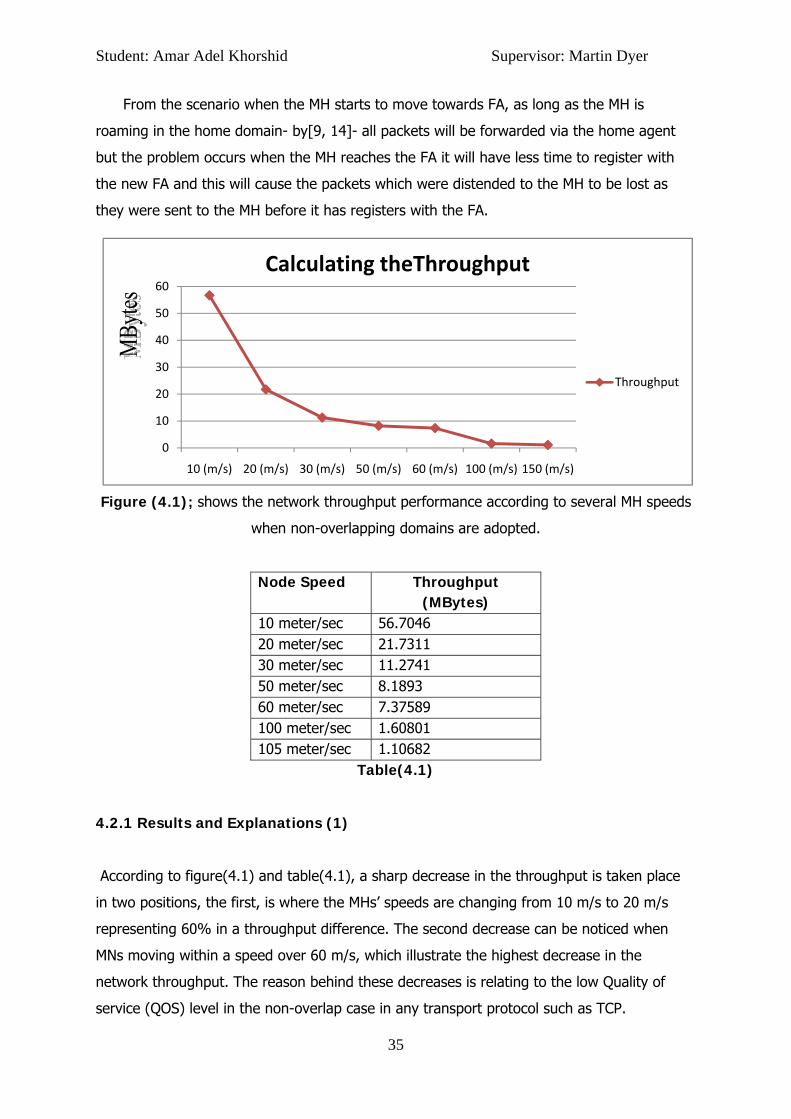
From the scenario when the MH starts to move towards FA, as long as the MH is
roaming in the home domain- by[9, 14]- all packets will be forwarded via the home agent
but the problem occurs when the MH reaches the FA it will have less time to register with
the new FA and this will cause the packets which were distended to the MH to be lost as
they were sent to the MH before it has registers with the FA.
Figure (4.1); shows the network throughput performance according to several MH speeds
when non-overlapping domains are adopted.
Node Speed Throughput (MBytes)
10 meter/sec 56.7046 20 meter/sec 21.7311 30 meter/sec 11.2741 50 meter/sec 8.1893 60 meter/sec 7.37589 100 meter/sec 1.60801 105 meter/sec 1.10682
Table(4.1)
4.2.1 Results and Explanations (1)
According to figure(4.1) and table(4.1), a sharp decrease in the throughput is taken place
in two positions, the first, is where the MHs’ speeds are changing from 10 m/s to 20 m/s
representing 60% in a throughput difference. The second decrease can be noticed when
MNs moving within a speed over 60 m/s, which illustrate the highest decrease in the
network throughput. The reason behind these decreases is relating to the low Quality of
service (QOS) level in the non-overlap case in any transport protocol such as TCP.
Student
the fram
end as
are in h
FAs wh
sent as
particul
time wi
then se
mention
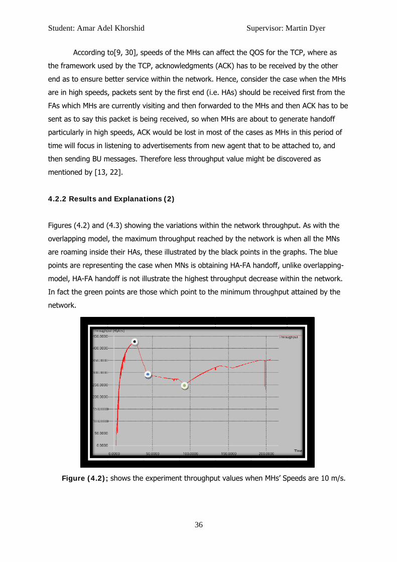
4.2.2 R
Figures
overlap
are roam
points a
model,
In fact t
network
Fig
t: Amar Ade
According t
mework use
to ensure b
high speeds
ich MHs are
to say this
arly in high
ll focus in li
ending BU m
ned by [13,
Results and
(4.2) and (
ping model
ming inside
are represen
HA-FA hand
the green p
k.
gure (4.2);
el Khorshid
to[9, 30], s
ed by the TC
better servic
, packets se
e currently v
packet is b
speeds, AC
stening to a
messages. T
22].
d Explanat
(4.3) showin
, the maxim
e their HAs,
nting the ca
doff is not i
points are th
; shows the
d
speeds of th
CP, acknow
ce within th
ent by the f
visiting and
being receive
CK would be
advertiseme
Therefore le
tions (2)
ng the varia
mum throug
these illust
ase when M
llustrate the
hose which
experimen
36
he MHs can
wledgments
e network.
first end (i.e
then forwa
ed, so when
e lost in mo
ents from n
ss throughp
ations withi
ghput reach
rated by th
MNs is obtain
e highest th
point to the
t throughpu
Su
affect the Q
(ACK) has t
Hence, con
e. HAs) shou
arded to the
n MHs are a
ost of the ca
ew agent th
put value m
n the netwo
ed by the n
e black poin
ning HA-FA
hroughput d
e minimum
ut values wh
upervisor: M
QOS for the
to be receiv
nsider the ca
uld be rece
e MHs and t
about to ge
ases as MHs
hat to be at
might be disc
ork through
network is w
nts in the g
handoff, un
decrease wi
throughput
hen MHs’ S
Martin Dyer
e TCP, wher
ved by the o
ase when th
ived first fro
then ACK ha
nerate hand
s in this per
ttached to,
covered as
hput. As wit
when all the
raphs. The
nlike overla
thin the net
t attained b
peeds are 1
r
re as
other
he MHs
om the
as to be
doff
riod of
and
h the
e MNs
blue
pping-
twork.
by the
10 m/s.

Student
Fig
This is d
overlap
each of
its bind
was obs
figure(4
through
point an
This is d
previou
handled
illustrat
less thr
basically
t: Amar Ade
ure (4.3);
due to the f
ped positio
f FA1 and FA
ing table an
served by d
More intere
4.3). In figu
hput decrea
nd the gree
due to the i
s handoff a
d with less l
ted in figure
oughput va
y informed
el Khorshid
shows the
fact where
n between
A2 has to a
nd 2- to add
discovering t
estingly, the
ure(4.2) the
se of 31%.
en point in f
increase in
and then rea
atency and
e(4.3) where
alues and m
by [7].
d
experiment
66% of the
FA1 and FA
ccomplish 2
d the new v
the data in
e green poin
slope from
On the oth
figure (4.3)
MHs speeds
ach a static
better QOS
e handoffs
ore probab
37
t throughpu
e mobile nod
A2. These w
2 update pr
visitor host t
trace files g
nt in figure
m the black p
her hand, th
shows 53%
s, as MHs in
throughput
S. While it is
are generat
ility of pack
Su
ut values wh
des in the to
will result in
ocesses, 1-
to its bindin
generated b
(4.2) is not
point to the
he gradient
% of through
n figure (4.2
t level, and
s the otherw
ted almost
kets to be d
upervisor: M
hen MHs’ Sp
opology are
more data
As to remov
ng table sim
by NS-2 in t
t in the sam
e green poin
difference b
hput decrea
2) will have
future han
wise in case
after each o
ropped. Th
Martin Dyer
peeds are 1
e in the sam
traffic over
ve the MHs
multaneously
these exper
me slope as
nt is resultin
between the
ase in the n
e time to fin
doffs can b
e of experim
other result
is behaviou
r
100 m/s.
me non-
head as
s from
y. This
riments.
in
ng in a
e black
etwork.
nish any
e
ment
ting in
r was
Student
4.3 No
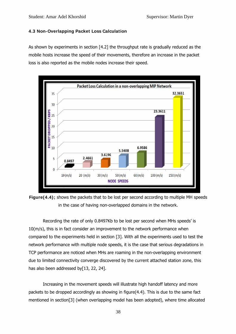
As show
mobile
loss is a
Figure
10(m/s)
compar
network
TCP per
due to l
has also
packets
mention
t: Amar Ade
on-Overlap
wn by exper
hosts increa
also reporte
e(4.4); show
in t
Recording t
), this is in
red to the e
k performan
rformance a
limited conn
o been addr
Increasing
s to be drop
ned in sectio
el Khorshid
pping Pack
riments in s
ase the spe
ed as the mo
ws the pack
the case of
the rate of o
fact conside
xperiments
nce with mu
are noticed
nectivity co
ressed by[1
in the move
pped accord
on[3] (whe
d
ket Loss Ca
section [4.2
eed of their
obile nodes
kets that to
having non
only 0.8497
er an impro
held in sec
ultiple node
when MHs
nverge disc
13, 22, 24].
ement spee
dingly as sho
n overlappi
38
alculation
] the throug
movements
s increase th
be lost per
n-overlapped
7Kb to be lo
ovement to t
ction [3]. W
e speeds, it
are roamin
covered by t
eds will illus
owing in fig
ng model h
Su
ghput rate i
s, therefore
heir speed.
r second acc
d domains i
ost per seco
the network
With all the e
is the case
ng in the no
the current
trate high h
gure(4.4). T
has been ad
upervisor: M
is gradually
e an increas
cording to m
in the netwo
ond when M
k performan
experiments
that serious
n-overlappi
attached st
handoff late
This is due to
opted), whe
Martin Dyer
y reduced as
e in the pac
multiple MH
ork.
MHs speeds’
nce when
s used to te
s degradatio
ng environm
tation zone,
ency and mo
o the same
ere time all
r
s the
cket
H speeds
is
st the
ons in
ment
, this
ore
fact
ocated
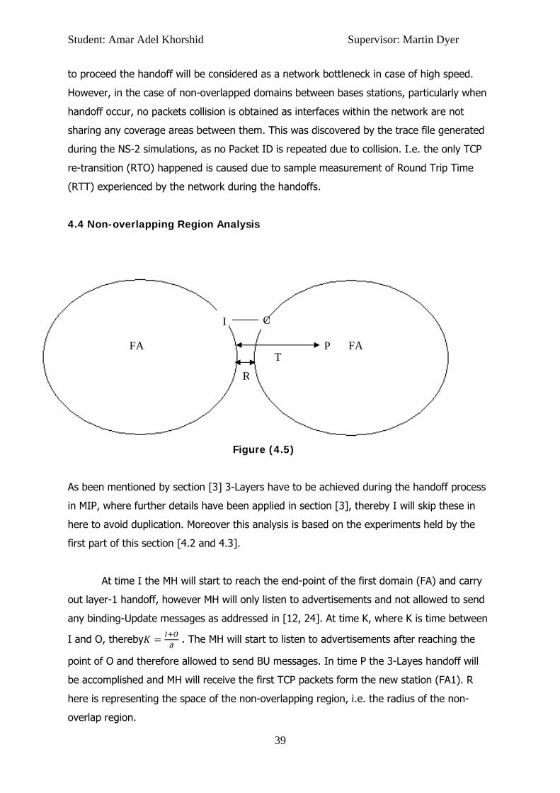
Student: Amar Adel Khorshid Supervisor: Martin Dyer
39
I O
PT
R
FAFA
to proceed the handoff will be considered as a network bottleneck in case of high speed.
However, in the case of non-overlapped domains between bases stations, particularly when
handoff occur, no packets collision is obtained as interfaces within the network are not
sharing any coverage areas between them. This was discovered by the trace file generated
during the NS-2 simulations, as no Packet ID is repeated due to collision. I.e. the only TCP
re-transition (RTO) happened is caused due to sample measurement of Round Trip Time
(RTT) experienced by the network during the handoffs.
4.4 Non-overlapping Region Analysis
Figure (4.5)
As been mentioned by section [3] 3-Layers have to be achieved during the handoff process
in MIP, where further details have been applied in section [3], thereby I will skip these in
here to avoid duplication. Moreover this analysis is based on the experiments held by the
first part of this section [4.2 and 4.3].
At time I the MH will start to reach the end-point of the first domain (FA) and carry
out layer-1 handoff, however MH will only listen to advertisements and not allowed to send
any binding-Update messages as addressed in [12, 24]. At time K, where K is time between
I and O, thereby . The MH will start to listen to advertisements after reaching the
point of O and therefore allowed to send BU messages. In time P the 3-Layes handoff will
be accomplished and MH will receive the first TCP packets form the new station (FA1). R
here is representing the space of the non-overlapping region, i.e. the radius of the non-
overlap region.

Student: Amar Adel Khorshid Supervisor: Martin Dyer
40
Similar to the overlapping case, non-overlapping here will suffer from three intervals times;
1- The interval time that MH takes to starts caring out Layer 1 handover to the time
where MN will start to send binding update message, we donate this by ξ. That is
ξ .
2- The time that MN takes to send the data to CN (the one-way delay time), we donate
this by 1.
3- The time that MH takes to receive the data from CN, we donate this by 2.
Besides, 2 and 3 will only be proceed after the MH reach O, i.e. finalizing ξ with no coverage
signals area placed between FA and FA1 because of non-overlapped domains structure.
Thus, we have ξ 1 2. Moreover we already know that the packet loss is
increasing gradually according to the MH speed, so we donate V as the movement direction
and speed of MH, that is .
Now let 1 donate the interval time when the MH starts caring layer 1 handoff to the
time when MH is in O, and S2 represent the interval time when MH caring out layer 1
handoff to the time when MH receives all the resides packets held on FA (if any). Hence
1 , 2 , where 1.
By the definition of , 1 2 one three cases behaviours are to be followed by the
network during any handoff situation.
4.4.1 Case (1):
S2 I S1 T
Figure(4.6)
Here, we have 2 , 1 2 1. 2 means that FA will forward
the resided packets before MH moves towards the end-point of FA. In the case of non-
overlapping domains it will always be the case that 1 , which means that MN will
receive the first packet from FA1 after reaching FA1 coverage domain, i.e. there will be no
collision event experienced by the network during the handoff as within the
overlapping case. As 2, 1 2, meaning that all resided
packets are to be forwarded before MN reaches the next station domain (FA1).

Student: Amar Adel Khorshid Supervisor: Martin Dyer
41
Concluding that smooth handoff is to be generated within this case with packet drops
probability of 0. Therefore:
.
4.4.2 Case (2):
I S2 S1 T
Figure(4.7)
This case is similar to case (1). Besides, resided packets held by FA will commonly be
dropped, as in a time point K, MH will roam in the region R with limited connectivity which in
turn will affect the throughput in this duration as addressed in [section [4] and in [4, 13,
23]] and resulting in more packets to be lost. Therefore:
, where (1).
4.4.3 Case (3):
I S1 S2 T
Figure(4.8)
This case is similar to case (2), however more packets are susceptible to be dropped during
the handoff process in this case. This is because time between I and S2 is high resulting in
risk of packets to be dropped as FA will need more time to forward any packets after MH
reach I. In addition, after MH reaches S1 all packets resided in FA will be dropped.
Therefore:
, where . (2).
Student: Amar Adel Khorshid Supervisor: Martin Dyer
42
Section 5
Calculating Delay Time
5.1 Overview
This section discuss the delay time generated in the MIPv4 network within two case studies,
the first one will give a general idea of the time delay behaviour when handoff occurred
within the overlapped area. The second case study will observe the behaviour of the MIP
sub-networks (i.e. agents) within the TCP.
This section is considering the stop point of this project, where any further
contribution by me or by anyone else can be started from here. Concluding that, as to solve
the high handoff latency it is worthwhile to solve the delay in wireless routers first and upon
that further investigation in the MIPv4 can be done efficiently.
5.2 End-to-end delay in overlapping area
End-to-end delay refers to the time taken for a packet to be transmitted across a network
from source to destination.[4]

Student: Amar Adel Khorshid Supervisor: Martin Dyer
43
In the first minute delay time is shown as (0ms) as the MH is still in it’s HA, as noticed there
is no delay reported until the MH starts getting closer to the overlapped area with the FA at
minute (6.01).
In the overlapped area delay time is slightly increased as handover is taking place,
again there is a delay increase noticed in minute (13.012566) as the mobile node is
roaming in a new foreign agent (FA). The delay time remains nearly the same until the end
of the simulation running time as the MH is roaming in different foreign agents and never
returns to its home agent.
Figure (5.1); shows the delay time calculation
Table (5.1)
5.3 End-to-End delay in TCP connections
NB: All TCP connections are enabled in this scenario.
At one point of this scenario two mobile nodes will end up sharing the same foreign
agent domain -MH and MH1 shares the same domain FA1-.
Description time delay Starts 0 0
closer to FA domain 6.0095 0.003077 overlapping with FA 7.7546 0.003077
Out of the overlapped area 7.8055 0.003077 reaches FA 13.012566 0.006231
overlapping with fa1 16.8147 0.006231 reaches fa1 21.099869 0.006230
Roaming In the FA1 domain 23.005895 0.006231
End to End Delay for MH
00.0010.0020.0030.0040.0050.0060.007
0 6.01 7.755 7.806 13.01 16.81 21.1 23.01
Running Time
Del
ay T
ime
Delay for MH

Student: Amar Adel Khorshid Supervisor: Martin Dyer
44
Delay time is increased at time (15.0144) as all mobile nodes in this point are roaming away
from the home agents domains.
Delay time is fairly steady until a slight increase in the delay time is reported at minute
(28.092933) where MH and MH1 are in the same domain (FA1). This can cause the packet
exchange between two mobile nodes in the same domain to be inefficient, therefore delay
time is increased to a certain level depending on the connection states.
Figure (5.2); time delay generated by TCP connections
Table (5.2)
description time delay starts 0 0
Out of the home agents domains 15.0144 0.00623 Out of the home agents domains 16.01242 0.00623 Out of the home agents domains 21.007564 0.006231
In the foreign agents domains 22.005476 0.006231 Two mobile nodes in the same domain 28.092933 0.006641
End to End Delay for all TCP Connections
00.0010.0020.0030.0040.0050.0060.007
0 15.0144 16.0124 21.0076 22.0055 28.0929
Running Time
Del
ay T
ime
Delay for MH
Student: Amar Adel Khorshid Supervisor: Martin Dyer
45
Section 6
Evaluation & Conclusion 6.1 Evaluating the project accuracy
Handoff in telecommunication computerised systems is the most issue disabling a good QOS
during the movement of the related mobile objects in the network. On the other hand, to
maintain an operating data flow service, problems generated by the handoff has to be
solved, or at least has to be taken to a certain level. With any network routing cells two
major models is adopted to handle such a handoff case, overlapped domains model and a
non-overlapped domains model.
In this project, the MIP network has been selected to evaluate the behaviours issues
resulted during the handoff in each model (overlapped and non-overlapped models).
Accuracy has always been under consideration along with this project, and therefore had to
be planed. Choosing the best overlapping area distance was the first step, this actually was
maintained as to give the best performance reached by the network when adopting the
overlapped-domains model. Indeed this concept has been merged along with accurate data
generated by the experiments in section [3]. The same method was allocated in the non-
overlapping model and experiments showed that with a non-overlapping area distance

Student: Amar Adel Khorshid Supervisor: Martin Dyer
46
between 55-65 meters are representing the best performance in the case of non-overlapped
domains, nevertheless, the work has been skipped to be aware of unnecessary data and
duplication; however the work can be seen in appendix [B].
The project was acquiring a total of 60 experiments to be done using the network simulator
(NS-2). Each in which has been ran 4 to 6 times as needed to enhance accuracy. However
the data generated by NS-2 in the trace file were complicated where each experiment trace
file was in the range of 22.9KB up to 1GB according to the simulation time and node speeds.
Therefore the second challenges was to simplify the confusion within these trace files, thus
AWK scripts was used to overcome these issue, and thereby more time was needed as to
improve my AWK skills, however this matter has been accomplished and accurate data have
been gathered from NS-2 trace file via AWK scripts.
6.2 Evaluating the Experiments Results
During the investigations in section [3,4] adopting the overlapped-domains model between
the network base-stations has leading to unsmooth data flow during the handoff when
compared to the case of having non-overlapped domains.
The table below (6.1) shows the throughput data summary in each model. Clearly a
throughput value enhancement is noticeable in the case of having non-overlapped domains
between network cells. For example with a MHs speeds of 10 (m/s), 48.2% increasing in the
throughput has been illustrated within the non-overlapped model when compared to the
overlapping model.
Table (6.1)
Similarly, packet drops are gradually increasing in both cases models according to
the MHs ground speed. However, as it can be seen from table(6.2), a non-overlapped based
model defining less packet loss per second resulting in 35.9% improvement in the packet-
MHs Speeds Throughput(MBytes) (Overlapping Case)
Throughput(MByets) (Non-overlapping case)
Improvement Percentage (%)
10 29.9732 56.7046 48.2% 20 14.4717 21.7311 34.5% 30 6.10617 11.2741 46.9% 50 4.51353 8.1893 45.9% 60 3.63719 7.37589 50.7% 100 1.65873 1.60801 -3.1% 150 1.33322 1.10682 -17%
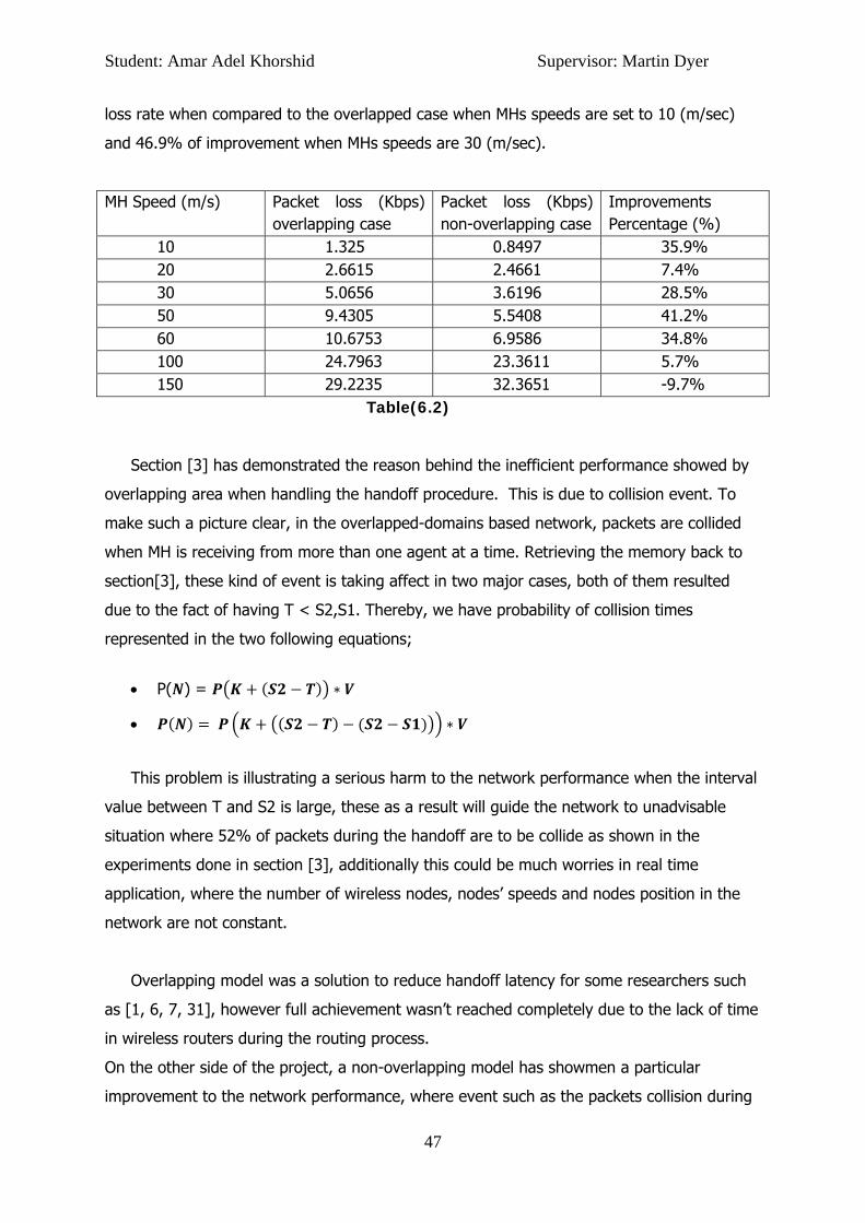
Student: Amar Adel Khorshid Supervisor: Martin Dyer
47
loss rate when compared to the overlapped case when MHs speeds are set to 10 (m/sec)
and 46.9% of improvement when MHs speeds are 30 (m/sec).
MH Speed (m/s) Packet loss (Kbps) overlapping case
Packet loss (Kbps) non-overlapping case
Improvements Percentage (%)
10 1.325 0.8497 35.9% 20 2.6615 2.4661 7.4% 30 5.0656 3.6196 28.5% 50 9.4305 5.5408 41.2% 60 10.6753 6.9586 34.8% 100 24.7963 23.3611 5.7% 150 29.2235 32.3651 -9.7%
Table(6.2)
Section [3] has demonstrated the reason behind the inefficient performance showed by
overlapping area when handling the handoff procedure. This is due to collision event. To
make such a picture clear, in the overlapped-domains based network, packets are collided
when MH is receiving from more than one agent at a time. Retrieving the memory back to
section[3], these kind of event is taking affect in two major cases, both of them resulted
due to the fact of having T < S2,S1. Thereby, we have probability of collision times
represented in the two following equations;
• P( ) =
•
This problem is illustrating a serious harm to the network performance when the interval
value between T and S2 is large, these as a result will guide the network to unadvisable
situation where 52% of packets during the handoff are to be collide as shown in the
experiments done in section [3], additionally this could be much worries in real time
application, where the number of wireless nodes, nodes’ speeds and nodes position in the
network are not constant.
Overlapping model was a solution to reduce handoff latency for some researchers such
as [1, 6, 7, 31], however full achievement wasn’t reached completely due to the lack of time
in wireless routers during the routing process.
On the other side of the project, a non-overlapping model has showmen a particular
improvement to the network performance, where event such as the packets collision during

Student: Amar Adel Khorshid Supervisor: Martin Dyer
48
the handoff has been solved. This has been proved in section [4] where no packets have
been collided during handoff. i.e. it is always the case that T > S2 and therefore no
complains has been made due to collision, because of suspending the authentication from
the previous agent as to send data to the MH when MH is reaching the new domain of the
next agent, these has been also addressed by [7, 19, 22, 28] when explaining the behaviour
of the non-overlapping area in a cellular based network.
The non-overlapping solution has only solved half of the puzzle. Problems are still
roaming around, even when non-overlapping model is adopted. According to sections [3,4]
the M-IP protocol in both models (overlapping & non-overlapping) is facing the problem of
packets to be dropped during the handoff, due to the number of un-forwarded packets in
agents when MHs are in high speed.
In advance, when handoff occurs and MH hasn’t actually finished the registration
with the new agent, its HA will assume that this MH’s COA is the currently visited FA address
and will keep sending data to this FA. By the time, MH will reach the new FA (Depending on
the MH speed) and will be out of range from the old FA, hence the old FA is still receiving
data from HA and will not stop until BU-message is been received by HA. Therefore theses
packets will be dropped. By [6, 9, 19] these type of problem is obtained due to routing time-
delay as shown by this project in section [5].
In the next side of the project, mathematical analysis was reported to illustrate the
network behaviour in both cases (overlapped and non-overlapped domains). In the
overlapping model 2 out of 6 cases are concerning with packets to be collided, and 3 cases
out of 6 are affected by the problem of packets to be un-forwarded by the old agent during
handoff. This has been showed in section [3] by the following equations;
- P( ) = in case 3
- , in case 5
- , in case 6
In the non-overlapping model, this problem has taken to a certain level where 2
cases out of 3 are suffering. However, none of the cases have affected by the fact of
packets to be collided during the handoff.

Student: Amar Adel Khorshid Supervisor: Martin Dyer
49
Another problem found in the non-overlapping model, that as long as S2 > I, i.e. the
MH reach the non-overlapping area, the network will start to endure a sharp degrade in its
performance. This is due to the limited connectivity service faced by the MH in this area,
[19, 28, and 30].
Constantly, experiments done in section [3, 4] and according to tables (6.1, 6.2) and
research done by[6, 11, 14, 17], are all pointing to the same fact, where MH speed and
overlapping & non-overlapping area distances are affecting the performance of the MIP
network. One of the important conclusion in this project was that, a non-overlapping model
is a better choice when MHs are less than 100 (m/s), however the overlapping model is
better otherwise. This is because of several reasons, each in which happening when MH
moving with high speed in this area such as; within the non-overlapping model TCP is taking
0.8/sec to be re-transmitted when such failure occurs [24], as well as time allocated for MH
to register with the new point of attachment will be short. This is actually explaining the
negative values generated in table [6.1 and 6.2].
6.3 Comparison with previous work
This project was contributing to discover the issues generated by the MIP network with
overlapped domains. In particular to investigate the reason behind the degrade performance
when such a model used and solve these by implementing a new network with non-
overlapped domains within the network. To be more specific, the non-overlapped-domains
has solved the problem of packets to be collided in the overlapping area during the handoff
resulting.
The point of interest is that researches such as [1, 2, 6, 31], were pointing to the
overlapped-domains model as a solution to the slow handoff process occurred with the non-
overlapping domains architecture. It is the case that fast handoff will be achieved by
overlapped-domains, but this will generate data traffic overhead due to collision as been
discovered by this project.
The lack of resources was the big issue faced during this project, where particular
comparison between the overlapping and non-overlapping cases using technical tool like NS-
2 were not found in any of research papers, besides only the work done by ZHAO et al , in
[31] and Pablo Vidales, et al in [22], were actually summarising voluble information in the
Student: Amar Adel Khorshid Supervisor: Martin Dyer
50
literature. However their work depends upon telecommunication mathematical theories and
was hard to be understood, but eventually the main concept was delivered.
The paper research done by Taeyeon Park and Arek Dadej in [28] was involved to
investigate the general characters of the Mobile IP network and used buffering mechanism
to solve the packet loss rate during the handoff. However, this would increase instantaneous
packet delay variation undesirable with real time application as mentioned by [5]. With voice
over IP delay time routing considering the disaster problem, in particular when objects such
as MH are moving with fast speeds. However Taeyeon Park and Arek Dadej were not very
specific about the MIP speeds and more importantly the topology design, where nothing has
been mentioned about non-overlapping domains model and related issues such as the
topology accuracy level left unclear.
The work done by Hsieh et al and Seneviratne in [25, 11] were helpful as it gave an
insight about the behaviour of the MIP protocol when overlapping domains are used,
nevertheless nothing has been mentioned about the non-overlapping domains model. In
terms of the overlapped domains model, the investigation done in [25] has showed similar
results to those in the project.
Most of the researches such as [1, 6, 8, 19], were offering their results based on a
very simply topology. The topology in the project was bigger and much closer to realistic.
Thereby, new investigations have been noticed, such as the degrade in the throughput
average when HA-FA handoff occurs, and further explanation was hard to be gathered until
I asked some friends working in the engineering department in Orange Telecommunication
company to provide me with related paper research such as the one in [7, 9].
Mathematical analysis was involved in this project, this has gave the project more
strength and offered an opportunity of a second prove methodology to be used beside the
technical one used by NS-2. ZHAO et al in [31] and the work in [12, 18] were the more
contributors who offered me with the basic knowledge about the overlapping area analysis
in a mathematical way. Due to the advance way written by [12, 18 and 31] points within the
overlapping area had to be discovered alone from other researches paper. For example the
point “I” in the middle of the overlap region has been investigated by [15] quoting;
“The handoff is initiated roughly after the MN is half way into the overlapping region”.

Student: Amar Adel Khorshid Supervisor: Martin Dyer
51
Similarly, non-overlapping domains model was analysed mathematically and
technically. With the mathematical analysis it was very hard to retrieve information due to
limited resources covering the subject in terms of non-overlapped domains. This however
has been overcame by gathering as much information as possible about the non-overlapping
region, and based on that I had implemented the mathematical analysis in way similar to
the one used to analysed the overlapping region. These as a result made further
comparisons between the two regions models to be easier and simpler for the reader.
In terms of comparison, once again, it is hard to assess due to the differing
complexities of the topologies of [6, 9, 15, 25] and those used in this project. However, the
performance observed by [1, 2, 25] in the Mobile IPv4 scenarios is very similar to that
observed by this project, although further investigation is required.
6.4 Conclusion
To conclude, Mobile IP protocol is been investigated deeply in a science way relaying upon
two methods, technical methodology using the network simulator NS-2 version 3.38 and
AWK scripts, and mathematically , to observe and explain the behaviour of the protocol
during the handoff.
While designing the topology I faced some difficulties in understanding the codes
used for implementation as information from external resources are very limited. However, I
have overcome this struggle and I have considered documenting the implementation steps
as it contains some technical details, which are essential to understand the fundamentals of
ns2 implementation approach.
The project has intended to reduce the high latency and packet loss generated in the
overlapping area (between stations domains) when handoff takes place. The observation
made according to two major factors, those in which are the overlapping area distances and
the Mobile device speeds.
For accuracy purposes, the distance of the overlapping area between domains have
been taken under consideration, and further investigation has been made. Interesting
results have appeared during the simulations, where 100 meters to be the overlapping area
Student: Amar Adel Khorshid Supervisor: Martin Dyer
52
size has taken the network to its preferable performance with less handoff latency. This is
due to the time given to the MHs to finish their handoff schemas.
Evaluating the performance of the Network protocol (TCP) in the case of having
overlapping domains architecture, resulted in a sharp degrade in the throughput slope and
increase in the number of packet loss when MHs increase their movement speeds
accordingly. These points has been illustrated in section 3 of the project.
Mathematical analysis has been adopted to discover the issues behind the high
latency generated in the overlapping area during the handoff process. Six cases have been
reported, which are representing the most probable handoff situations that can be faced by
such a network. Additionally, mathematical formulas have been formulised as to explain the
number of packets to be lost in each of the 6-cases. I’ve investigated that degrade and
increase within the throughput and the packet loss respectively, has obtained due to the
interference collision event in the overlapped areas. In particular, collision during the
handoff is reaching its maximum level when MH reaches a specific point in the overlapped
area represented by W, where the most the MH stays in this point the more packet collisions
occur. Section 3 is showing these in more details.
Section 4 has implemented the target point intended by the project. Adopting the
concept of non-overlapped domains was the main idea in this section, these as to show the
performance of the MIP and solve the collision occurrence discovered in section[3]. The MIP
Network has been tested in this model along with multiple MHs speeds. Experiments results
showed the same performance as with those when overlapping domains model used, but
with enhancement in the slopes for both of the throughput and the packets loss, concluding
in a solution to the packet loss observed due to collision in packets transmission process.
Moreover, Technical and mathematical analysis has been applied here, as well, to report the
new investigations and to build further discussions when monitoring the behaviour of the
non-overlapped domains based network.
Within the non-overlapping area no collision is been reported and therefore increase
in the network performance has been reached. However the non-overlapping area has also
showed side-effects in terms of less QOS (Quality Of Service) when such a MH moves deeply
inside the non-overlapped zone. This is as been proved is due to connectionless situation
roaming in this area. Therefore I’ve came with the conclusion of, in larger none overlapped

Student: Amar Adel Khorshid Supervisor: Martin Dyer
53
scenarios (e.g.200m distance between wireless hosts) they show more handoff latency and
more packet loss as the distance between the Agents increases. Therefore overlapping the
nodes can considered as a good idea as it reduces the packet loss to a certain level.
Furthermore the project showed that the reason behind the high latency in both of
the cases (overlapped and non-overlapped domains) is due to time delay in wireless routing
within the MIP protocol. Investigations showed that delay time is increased when mobile
nodes roam away from the home agent domains and that’s due to the handoff experienced
in this point. When two nodes are sharing the same domain, packet exchange between the
mobile nodes is inefficient. Therefore delay time is increased to a certain level depending on
the connection states. This was mentioned as to give an insight for further work and
investigation by anyone who interested in solving the high handoff latency in the mobile IP
protocol.
The evaluation part of this project has evaluated the project in several points; the
accuracy level followed when designing the topology as to result in accurate data when
experimenting the network performances, whether overlapped domains or non-overlapped
domains adopted. Secondly I have made a comparison between the two performances
generated by the overlapped-domains model and the non-overlapped-domains model,
illustrating how the non-overlapped-model has reduced the latency and packet loss to a
certain level during the handoff.
Moreover, I have given an overview of what type of researches papers are in the literature
and what kind of contribution this project has made.
Student: Amar Adel Khorshid Supervisor: Martin Dyer
54
References
[1] Aisha H. A. Hashim, Farhat Anwar, Shaffiah Mohd and Hatina Liyakthalikh. Mobility
Issues in Hierarchical Mobile IP. 3rd International Conference: Sciences of Electronic,Technologies of Information and Telecommunications (2005).
[2] 7. Aisha Hassan Abdalla Hashim, Fauzana Ridzuan, and Nazreen Rusli. Evaluation of handover latency in intra- domain mobility, world academy of science, engineering and technology, volume 6, 2005, ISSN 1307-6884.
[3] 5. Charles, e. Perkins. (1998), mobile IP design principles and practices: route
optimization, Addison Wesley Longman.
[4] Chee Kong LAU. Improving Mobile IP Handover Latency TCP in End-to-End time delay. University of New South Wales. 2006.
[5] Christer Åhlund1, Robert Brännström1, and Arkady Zaslavsky2. M-MIP: Extended Mobile IP to Maintain Multiple Connections to Overlapping Wireless Access Networks. www.springerlink.com/index/NR77DHHDNM4HU2AW.pdf. Last accessed [24/02/2009].
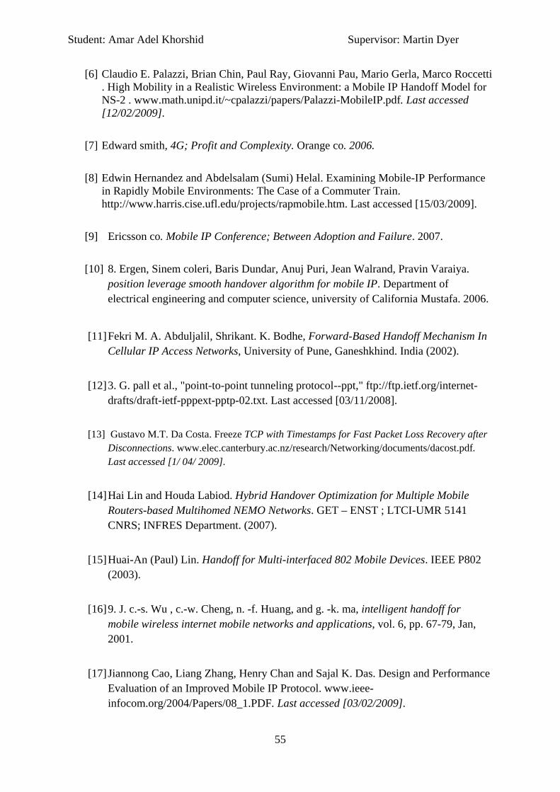
Student: Amar Adel Khorshid Supervisor: Martin Dyer
55
[6] Claudio E. Palazzi, Brian Chin, Paul Ray, Giovanni Pau, Mario Gerla, Marco Roccetti . High Mobility in a Realistic Wireless Environment: a Mobile IP Handoff Model for NS-2 . www.math.unipd.it/~cpalazzi/papers/Palazzi-MobileIP.pdf. Last accessed [12/02/2009].
[7] Edward smith, 4G; Profit and Complexity. Orange co. 2006.
[8] Edwin Hernandez and Abdelsalam (Sumi) Helal. Examining Mobile-IP Performance in Rapidly Mobile Environments: The Case of a Commuter Train. http://www.harris.cise.ufl.edu/projects/rapmobile.htm. Last accessed [15/03/2009].
[9] Ericsson co. Mobile IP Conference; Between Adoption and Failure. 2007.
[10] 8. Ergen, Sinem coleri, Baris Dundar, Anuj Puri, Jean Walrand, Pravin Varaiya. position leverage smooth handover algorithm for mobile IP. Department of electrical engineering and computer science, university of California Mustafa. 2006.
[11] Fekri M. A. Abduljalil, Shrikant. K. Bodhe, Forward-Based Handoff Mechanism In
Cellular IP Access Networks, University of Pune, Ganeshkhind. India (2002).
[12] 3. G. pall et al., "point-to-point tunneling protocol--ppt," ftp://ftp.ietf.org/internet-drafts/draft-ietf-pppext-pptp-02.txt. Last accessed [03/11/2008].
[13] Gustavo M.T. Da Costa. Freeze TCP with Timestamps for Fast Packet Loss Recovery after Disconnections. www.elec.canterbury.ac.nz/research/Networking/documents/dacost.pdf. Last accessed [1/ 04/ 2009].
[14] Hai Lin and Houda Labiod. Hybrid Handover Optimization for Multiple Mobile Routers-based Multihomed NEMO Networks. GET – ENST ; LTCI-UMR 5141 CNRS; INFRES Department. (2007).
[15] Huai-An (Paul) Lin. Handoff for Multi-interfaced 802 Mobile Devices. IEEE P802 (2003).
[16] 9. J. c.-s. Wu , c.-w. Cheng, n. -f. Huang, and g. -k. ma, intelligent handoff for mobile wireless internet mobile networks and applications, vol. 6, pp. 67-79, Jan, 2001.
[17] Jiannong Cao, Liang Zhang, Henry Chan and Sajal K. Das. Design and Performance Evaluation of an Improved Mobile IP Protocol. www.ieee-infocom.org/2004/Papers/08_1.PDF. Last accessed [03/02/2009].

Student: Amar Adel Khorshid Supervisor: Martin Dyer
56
[18] Jongjin Park and Youngsong Mun, The Layer 2 Handoff Scheme for Mobile IP over IEEE 802.11 Wireless LAN, SpringerLink Journal . (2004). Vol. 3043/2004. PP 1144-1150. ISNB: 978-3-540-22054-1.
[19] Md. Mohiuddin Khan, Md. Arifur Rahman Bhuyan, Fiash Kiswar, A. S. M.
Ashique Mahmood. Overview and Comparison of Methods for Minimizing HandOff Latency in Mobile IP. IJCSNS International Journal of Computer Science and Network Security, VOL.8 No.3, March 2008.
[20] 1. Mobile ip (2004-2005) mobile ip components. http://www.dpo.uab.edu/~amit81/mip%20pages/terminology.htm. Last accessed [27/10/2008].
[21] 2. Mobile networking through mobile IP. http://www.cs.colorado.edu/~rhan/csci_7143_002_fall_2001. Last accessed [02/11/2008].
[22] Pablo Vidales, Leo Patanapongpibul, Glenford Mapp, Andy Hopper. Experiences with Heterogeneous Wireless Networks,Unveiling the Challenges. www.mdx.ac.uk/eis/research/groups/docs/HetNets04-Vidales.pdf. 2004. Last accessed[12/3/2009].
[23] R. Ramjee, T. La Porta, S. Thuel, K. Varadhan and S.Y. Wang. HAWAII: A Domain-based Approach for Supporting Mobility in Wide-area Wireless Networks. www.cse.psu.edu/~tlp/paper/hawaii.ps. Last accessed [12/02/2009].
[24] Ramon Caceres, Liviu Iftode. AT &T conference :Improving the Performance of Reliable Transport Protocols in Mobile Computing Environments. 2005.
[25] Robert Hsieh, Zhe Guang Zhou, Aruna Seneviratne. S-MIP: A Seamless Handoff Architecture for Mobile IP. www.ieee-infocom.org/2003/papers/43_04.PDF. Last accessed [02/03/2009].
[26] S.McCanne and S. Floyd. The network simulator — ns-2. http://www.isi.edu/nsnam/ns/, Last accessed [30/12/2007].
[27] Satyajit Chakrabarti, Son T. Vuong, Anirban Sinha, Rajashree Paul. BlueMobile – A mobile IP based Handoff system for Bluetooth, 802.11 and GPRS links. IEEE Consumer Communications and Networking Conference (CCNC) held at Las Vegas,

Student: Amar Adel Khorshid Supervisor: Martin Dyer
57
Nevada, USA.Gustavo. TCP with Timestamps for Fast Packet Loss Recovery after Disconnections. 2005.
[28] Taeyeon Park and Arek Dadej. OPNET Simulation Modeling and Analysis of Enhanced Mobile IP www.cse.iitb.ac.in/~varsha/allpapers/wireless/wcnc2003/opnet-enh-mob-IP.pdf . Last accessed [29/01/2009].
[29] 4. The TCP/IP code (2001) IP security (IPsec) protocols http://www.tcpipguide.com/free/t_ipsecurityipsecprotocols.htm. Last accessed [15/11/2008].
[30] Vijay K. Madisetti and Antonios D. Argyriou. Transport Layer QoS Management for Wireless Multimedia Services(2002). www.soft-networks.com/vkm-vomo.pdf. Last accessed[23/02/2009].
[31] ZHAO Qing-Lin, LI Zhong-Cheng , FENG Li , YANG Jian-Hua. Characterization of Handoff in Mobile IP. Journal of Software Vol.16, No.7 . 2005.

58
Appendix A
Personal Reflection
“All is well that ends well” and that is what I would like to think at this moment of time. It is
a sigh of relief, It is the time to hand in my final year project. Looking back in the time, I
can recall each and every moment of the time I spent in University of Leeds in pursuit of
“B.Sc computer Science.”. The time passed in a jiffy. There were highs and lows throughout
this period, both academically and personally, however, each passing thing has been a
learning experience. It started 2005 after summer, the first time I landed in the UK. I was
taken aback with the pace of the country. Everybody seemed to be busy, talking on the
phones, walking fast as if contesting in the marathon. But just a few acquaintances were
enough to familiarize me with the country. I would attribute it to desire I had to learn.

59
Choices & Challenges
Networking is the field which interacting my attention since I was 12 years old, when
internet revolution has started in my country. The idea of Mobile IP was abduct me in
moments, I started to look around about the inspired concept by my friends who are
working in telecommunication companies in my country and abroad. Maintaining voice over
IP within multiple networks in the world using the mobile phone will take the social
communities to a position where communication is much easier and simple with less money
cost. Maybe you would say that I am very ambitious, but I really want to be involved in
mobility concept even with little contributions. These was the only thing which made me
stay survive when things appeared complicated with me during this project.
When it came to select the project, it was the time of proving rather than choosing a
topic. The project topic has been chosen by my own satisfaction, but this is not enough
where I had to prove that to the staff in the school of computing. In the first meeting with
my supervisor I’ve been told that the project topic is been agreed and I can chose it to
accomplish the 40 credits, by this time I was really happy and flying like a bird.
The challenges were always along with this project, as I made this decision by
myself I knew that it is going to be my responsibility to guide myself to the correct path and
making a good work. In particular when good work can make a difference between a
classification degree of IIi and IIii.
The second challenge I faced is due to my basic background in this field I had to
develop my skills and discover the concepts and the protocols within the literature. Thereby
I had to make a good split between the project sections itself and between the project and
the other modules. Therefore I made the first semester for researching and gathering
information from different resources.
The third challenge was when the mathematical analysis has taken a place along
with this project, so I had to split my time to develop my technical skills with TCL-NS(2) and
AWK programming languages and to improve my mathematical analysis.
I do believe that life is an experience. During the final year project I have learnt
many things which in turn will help me in my future. One thing that I consider as an

60
achievement is that nothing is hard to be reached unless you wanted to be, where reaching
the target is not possible while you give it the required effort.
Recommendations
For those who wish to undertake a final year dissertation I would recommend the following;
• Be always a wear of choosing the topic that really interests you as when time is
tough this is the only thing that will make you stand back again. More importantly if
you wish to choose the topic by your own, be sure to draw a clear picture of your
plan and any possible risks – maybe not following mine.
• Issues and problems are all natural facts emerging within these stage, so these
should not take your ambitious and motivations down, but this should make you
more resilient and stronger.
• Discuss your project issues with your supervisor and don’t leave that until the last
minutes, therefore I really recommend you to not miss your supervisor meetings as
this will keep you update of your progress and will enable the supervisor to assist
your effort along the progression.
• Be sure to document any suggestions and observations discovered while conducting
the technical part. In addition, I would really advice you to accomplish the technical
part as soon as possible, I am not saying that do them roughly, as final product is
important for your results accuracy, but make sure to give an enough time for
documenting your report, as this is the only thing that will be assisted.
• Always plan to get a first class in your final year project as this will target you to
spend as much effort as can be done by good quality and planning.

61
• Finally, I would say that nothing is impossible, it is just the fact where can you reach
the level you want or not, and be ready for any problems that might face you during
the project phases and immediately deal with it.
A statement about the relevance of the project to
the degree course I am doing
I have always been interested in the network field and particularly in mobility and the
relevant wireless connections, this project has gave me a broad knowledge about mobility,
the development process of different (wired and wireless) networks and how to investigated
the efficiency of the data transport by the TCP and UDP protocols. This general
understanding is important for me as a computer science student as it helped me improving
my computing experiences and skills.
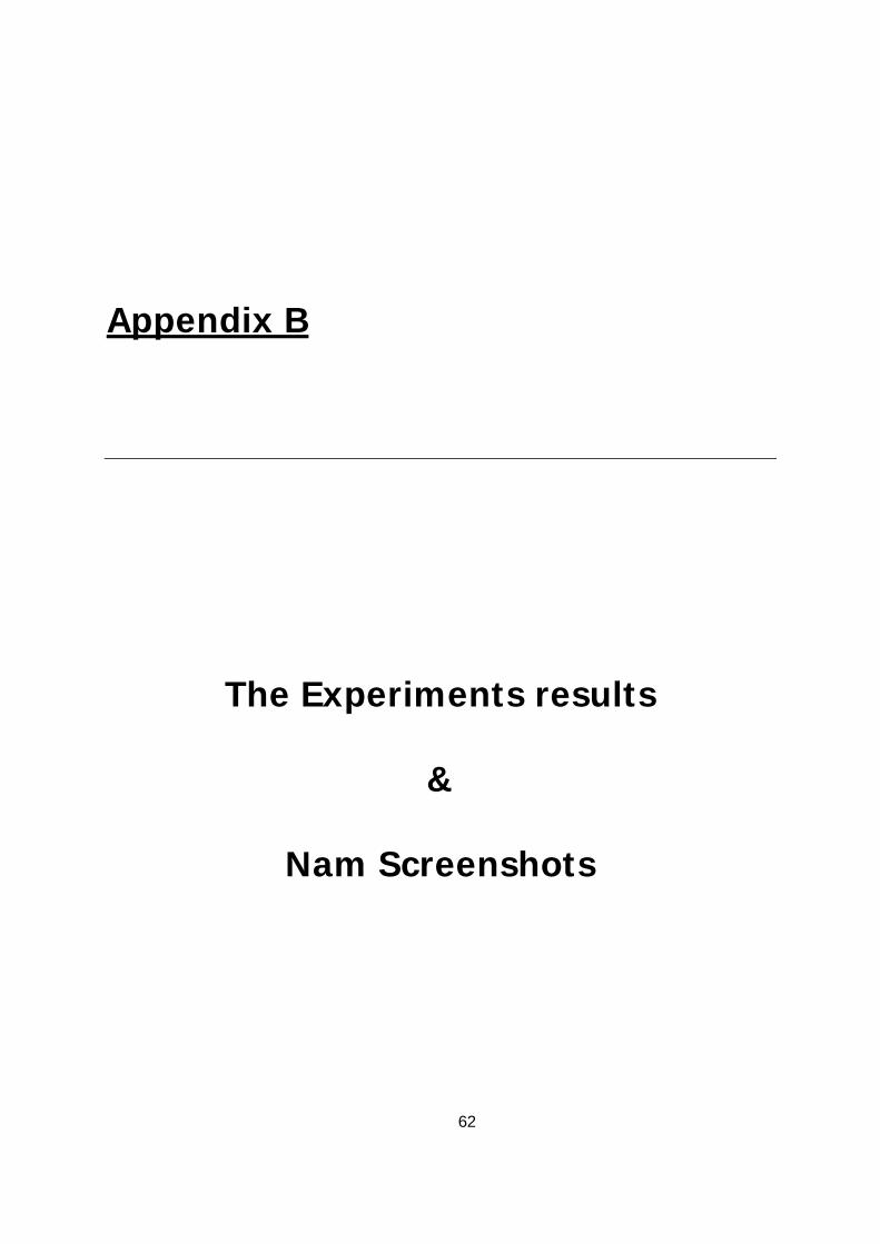
62
Appendix B
The Experiments results
&
Nam Screenshots

63
Some of the Experiments Results
The throughput calculation in an overlapped-domains model when MHs stays in the
overlapping region for 0/sec

64
The throughput calculation in an overlapped-domains model when MHs stays in the
overlapping region for 3/sec
The number of dropped packets caused by the collision in the overlapping area when MH
stays in the region for 3/sec.
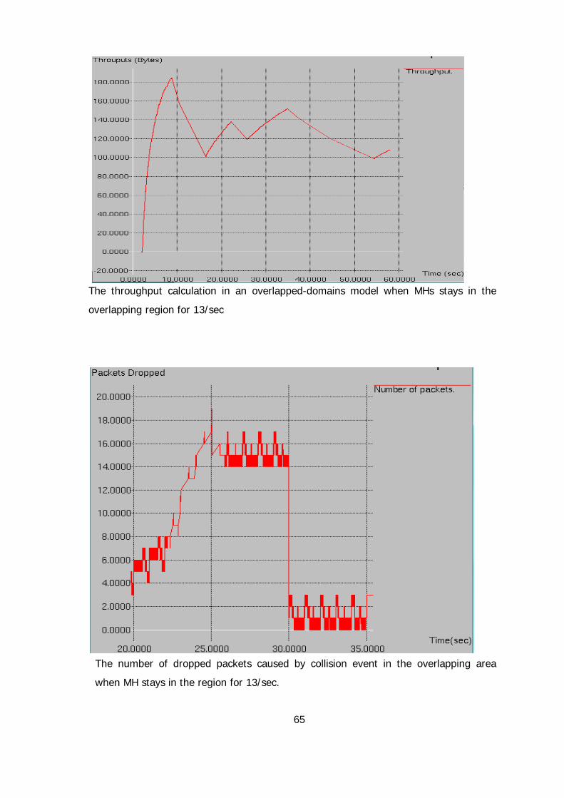
65
The throughput calculation in an overlapped-domains model when MHs stays in the
overlapping region for 13/sec
The number of dropped packets caused by collision event in the overlapping area
when MH stays in the region for 13/sec.
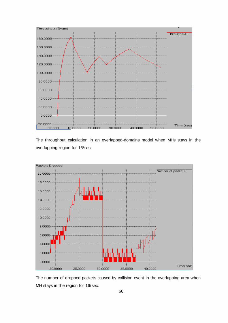
66
The throughput calculation in an overlapped-domains model when MHs stays in the
overlapping region for 16/sec
The number of dropped packets caused by collision event in the overlapping area when
MH stays in the region for 16/sec.
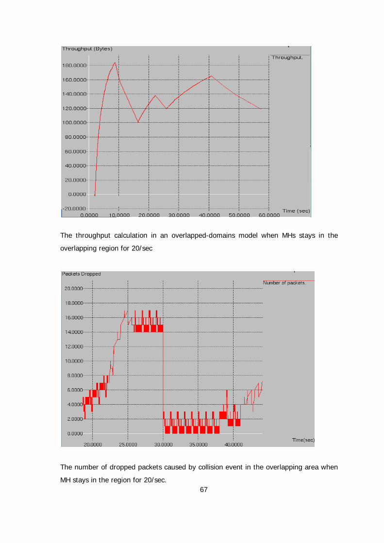
67
The throughput calculation in an overlapped-domains model when MHs stays in the
overlapping region for 20/sec
The number of dropped packets caused by collision event in the overlapping area when
MH stays in the region for 20/sec.
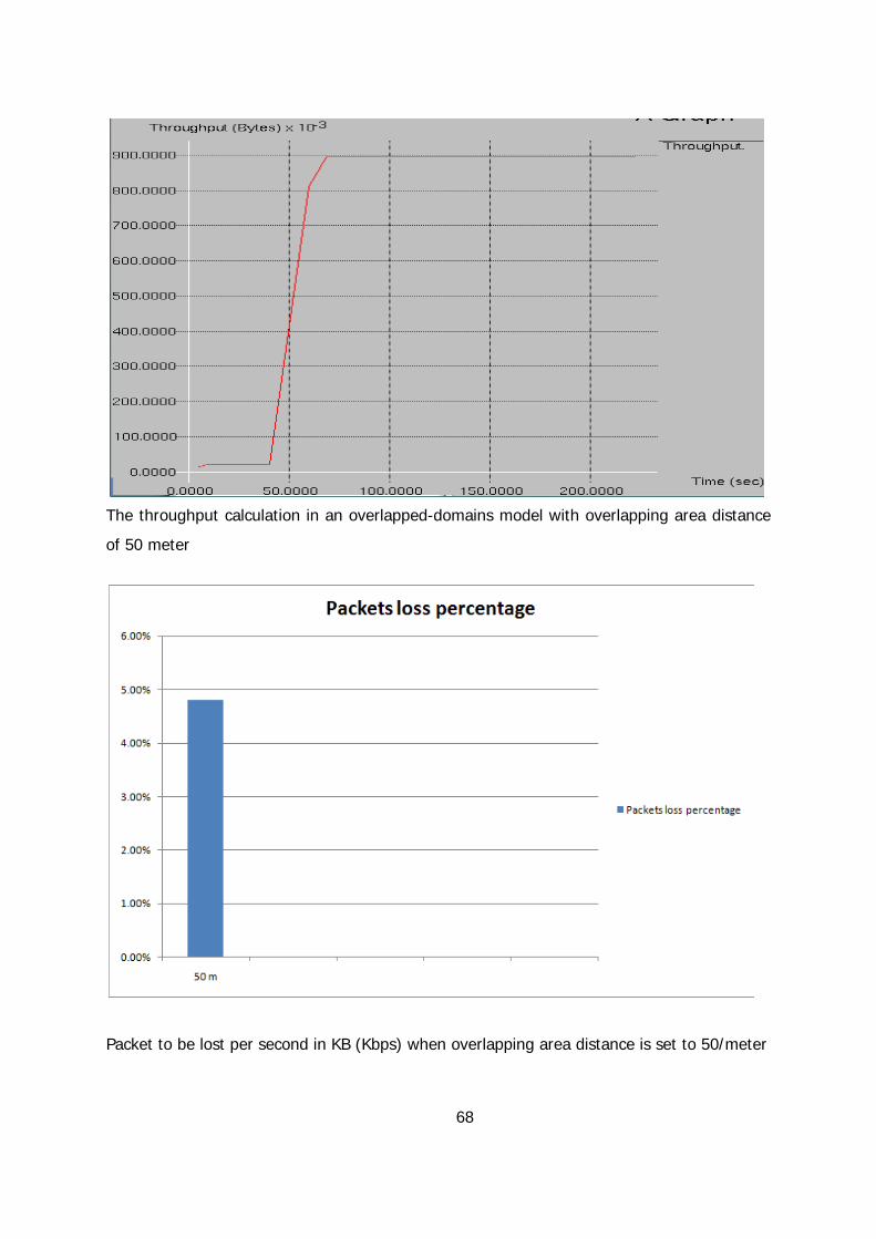
68
The throughput calculation in an overlapped-domains model with overlapping area distance
of 50 meter
Packet to be lost per second in KB (Kbps) when overlapping area distance is set to 50/meter

69
The throughput calculation in an overlapped-domains model with overlapping area distance
of 70 meter
Packet to be lost per second in KB (Kbps) when overlapping area distance is set to 70/meter

70
The throughput calculation in an overlapped-domains model with overlapping area distance
of 100 meter
Packet to be lost per second in KB (Kbps) when overlapping area distance is set to
100/meter

71
The throughput calculation in an overlapped-domains model with overlapping area distance
of 120 meter
Packet to be lost per second in KB (Kbps) when overlapping area distance is set to
120/meter

72
The throughput calculation in an overlapped-domains model with overlapping area distance
of 170 meter
Packet to be lost per second in KB (Kbps) when overlapping area distance is set to
170/meter
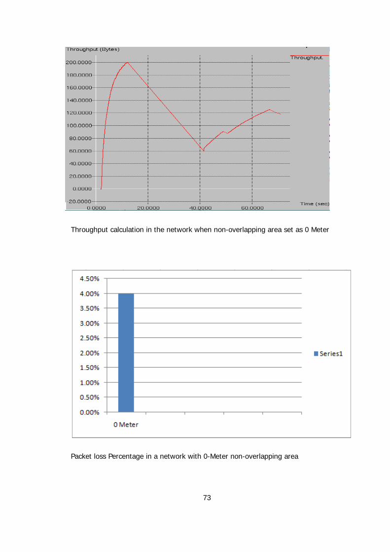
73
Throughput calculation in the network when non-overlapping area set as 0 Meter
Packet loss Percentage in a network with 0-Meter non-overlapping area

74
Throughput calculation in the network when non-overlapping area set as 20 Meter
Packet loss Percentage in a network with 20-Meter non-overlapping area

75
Throughput calculation in the network when non-overlapping area set as 40 Meter
Packet loss Percentage in a network with 40-Meter non-overlapping area
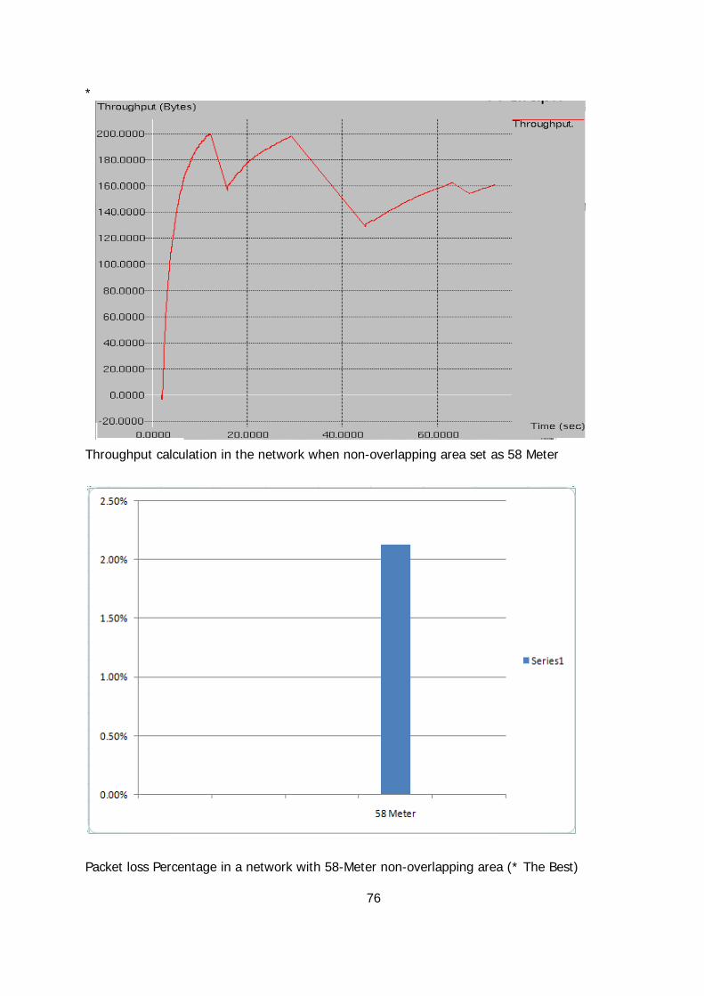
76
*
Throughput calculation in the network when non-overlapping area set as 58 Meter
Packet loss Percentage in a network with 58-Meter non-overlapping area (* The Best)

77
Throughput calculation in the network when non-overlapping area set as 100 Meter
Packet loss Percentage in a network with 100-Meter non-overlapping area

T
m
The Pac
are set
he through
meter/sec
cket to be
to 10 (Mete
put calcula
Dropped pe
er/sec)
tion in an o
er second i
78
overlapped-
n an overla
-domains m
apped-doma
model with
ains model
MHs’ speed
when MHs’
ds of 10
’ speeds
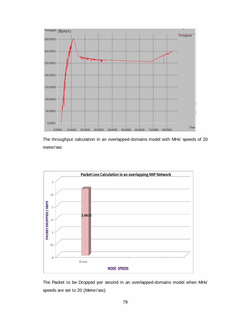
79
The throughput calculation in an overlapped-domains model with MHs’ speeds of 20
meter/sec
The Packet to be Dropped per second in an overlapped-domains model when MHs’
speeds are set to 20 (Meter/sec)
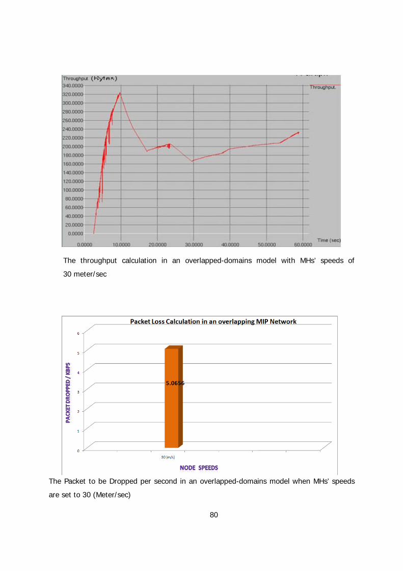
80
The throughput calculation in an overlapped-domains model with MHs’ speeds of
30 meter/sec
The Packet to be Dropped per second in an overlapped-domains model when MHs’ speeds
are set to 30 (Meter/sec)

81
The throughput calculation in an overlapped-domains model with MHs’ speeds of 50
meter/sec
]
The Packet to be Dropped per second in an overlapped-domains model when MHs’ speeds
are set to 50 (Meter/sec)

82
The throughput calculation in an overlapped-domains model with MHs’ speeds of 60
meter/sec
The Packet to be Dropped per second in an overlapped-domains model when MHs’
speeds are set to 60 (Meter/sec)

83
The throughput calculation in an overlapped-domains model with MHs’ speeds of 100
meter/sec
The Packet to be Dropped per second in an overlapped-domains model when MHs’
speeds are set to 100 (Meter/sec)

84
The throughput calculation in an overlapped-domains model with MHs’ speeds of 150
meter/sec
The Packet to be Dropped per second in an overlapped-domains model when MHs’
speeds are set to 150 (Meter/sec)
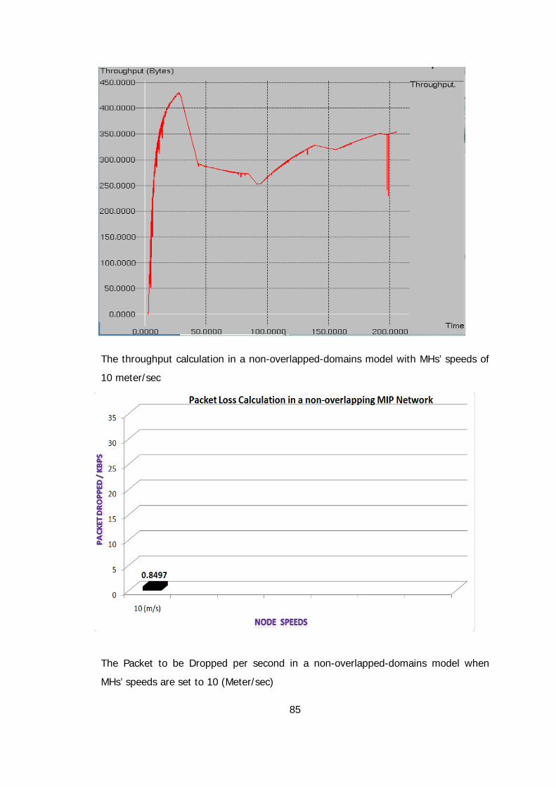
85
The throughput calculation in a non-overlapped-domains model with MHs’ speeds of
10 meter/sec
The Packet to be Dropped per second in a non-overlapped-domains model when
MHs’ speeds are set to 10 (Meter/sec)

86
The throughput calculation in a non-overlapped-domains model with MHs’ speeds of
20 meter/sec
The Packet to be Dropped per second in a non-overlapped-domains model when
MHs’ speeds are set to 20 (Meter/sec)

87
The throughput calculation in a non-overlapped-domains model with MHs’ speeds of
30 meter/sec
The Packet to be Dropped per second in a non-overlapped-domains model when
MHs’ speeds are set to 30 (Meter/sec)

88
The throughput calculation in a non-overlapped-domains model with MHs’ speeds of
50 meter/sec
The Packet to be Dropped per second in a non-overlapped-domains model when
MHs’ speeds are set to 50 (Meter/sec)

89
The throughput calculation in a non-overlapped-domains model with MHs’ speeds of
60 meter/sec
The Packet to be Dropped per second in a non-overlapped-domains model when
MHs’ speeds are set to 60 (Meter/sec)

90
The throughput calculation in a non-overlapped-domains model with MHs’ speeds of
100 meter/sec
The Packet to be Dropped per second in a non-overlapped-domains model when
MHs’ speeds are set to 100 (Meter/sec)

91
The throughput calculation in a non-overlapped-domains model with MHs’ speeds of
150 meter/sec
The Packet to be Dropped per second in a non-overlapped-domains model when
MHs’ speeds are set to 150 (Meter/sec)
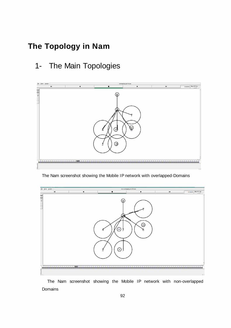
92
The Topology in Nam
1- The Main Topologies
The Nam screenshot showing the Mobile IP network with overlapped-Domains
The Nam screenshot showing the Mobile IP network with non-overlapped
Domains

93
2- Topology used to calculate the overlapped
and non-overlapped area distances
The topology used to calculate the optimal overlapping distance
The topology used to calculate the optimal non-overlapping distance