improvements in feeder protection— providing a primary and
TRANSCRIPT

Improvements in Feeder Protection— Providing a Primary and Backup Relay System Utilizing One Relay per Feeder
Mark Oens Snohomish County PUD
Craig Lange Schweitzer Engineering Laboratories, Inc.
Presented at the DistribuTECH Conference
San Diego, California February 4–6, 2007
Originally presented at the 33rd Annual Western Protective Relay Conference, October 2006
1
Improvements in Feeder Protection—Providing a Primary and Backup Relay System Utilizing One Relay per Feeder
Mark Oens, Snohomish County PUD Craig Lange, Schweitzer Engineering Laboratories, Inc.
Abstract—Today many electric utilities will not rely on a single relay per feeder to provide the protection required. In recent history, when electromechanical relays were common, there was always a “built-in” backup relay. With the advent of modern three-phase microprocessor-based relays, other alter-natives are required for backup. To meet this requirement, at least one additional relay is required to provide some form of backup tripping in case the primary protective relay fails. Existing alternatives include a bus backup relay, two relays per feeder (primary and backup), or dual primary relays. Dual primary relays are common on transmission line systems but not as common on distribution feeder circuits. Ultimately, the objective is to provide continuity to the main bus and continue protection to the feeder if a relay is taken out of service and a feeder fault occurs.
This paper provides examples of primary and backup relay systems and how they are applied at Snohomish County Public Utility District. This paper also describes a unique relay system installed by Snohomish County PUD that provides both primary and backup protection, utilizing a single microprocessor-based relay per feeder. Each relay provides primary protection for an assigned feeder, plus backup protection for an adjacent feeder. The same relay is used for automatic reclosing and control of the assigned feeder. The testing performed to verify the correct operation of the new relay system is discussed. This paper also briefly discusses the design and how it reduced the amount of equipment with high failure rates, including the role of communication and its effect on the wiring and control system. This design has been implemented at the District’s Village Substation.
I. INTRODUCTION Snohomish County PUD (District) is located approxi-
mately 20 miles north of Seattle. The District serves over 300,000 customers, and the service area is over 2,200 square miles. The District has 80 substations; each substation typically has 4 feeders and 1000 customers per feeder. Like many utilities, a variety of protection devices are used in the substations and on the feeder circuits. The District is served by Bonneville Power Administration from three locations at 115 kV. The District operates a 115 kV transmission system and a 12.47 kV distribution system with both overhead and underground conductors. The feeder portions of the distribution system are normally designed to carry a maximum of 600 amperes, while the laterals are rated at lesser amounts. Typical substations contain a 16/22/28 MVA wye-delta-wye 115 kV to 12.47 kV power transformer. Overcurrent relays
monitor the phase and neutral currents by means of current transformers (CTs) and make tripping decisions based upon these current values and settings.
A. District Protection Philosophy All distribution breakers can be tripped by overcurrent
relays. Some of the older substations utilize electromechanical relays, while newer and retrofitted substations use microprocessor-based relays. Bank overcurrent relays are set to protect the transformer and provide backup protection for the feeder.
On most District feeders, both instantaneous and time-delayed tripping are used. Coordination of overcurrent devices (e.g., relays, reclosers, fuses) is maintained using tap, time dial, etc.
The District employs a fuse-saving scheme. Instantaneous tripping is intended to operate before a line fuse for a fault beyond the fuse—allowing an opportunity for a momentary fault to clear itself without blowing the fuse and causing a permanent outage to customers. If the circuit contains a recloser, the instantaneous settings are set to not overreach the recloser. Instantaneous tripping at the District is enabled on the first trip only.
Not all feeders have instantaneous tripping. An evaluation of each circuit is made by the protection engineer to determine if instantaneous tripping is needed. Instantaneous tripping is often removed on circuits that serve industrial loads or are primarily underground feeders. Underground faults are typically permanent and fuse-saving is not beneficial. In these cases, instantaneous tripping is not employed, because a short outage can be just as bad for an industrial customer as a prolonged outage. This allows a fuse to clear the fault without having the breaker trip first.
When available, the District employs a second instan-taneous setting (Inst 2). This is typically set to 95% of the maximum three-phase and single-phase bus fault duty. When a fault occurs that exceeds the Inst 2 setting, the relay is driven to lockout and reclosing is prohibited.
A circuit is placed in nonreclose when a crew is working on a circuit. If a fault occurs, the breaker will trip and not reclose. Instantaneous tripping is employed on all circuits that are placed in nonreclose.

2
B. District Primary and Backup Systems
1) Electromechanical Relays The majority of the substations use electromechanical
relays. These electromechanical relays are at least 20 years old, and many are over 40 years old. The District has four electromechanical relays per feeder (one for each phase, and one for ground). This configuration provides a built-in backup. If the ground overcurrent relay fails, the phase over-current relay will pick up and trip. If a line-to-line fault occurs and one of the phase relays fails, the other will trip the circuit (see Fig. 1).
Two major disadvantages of electromechanical relays are the requirement for regular maintenance and the lack of event reports. The District requires electromechanical relays to be maintained every two years. With dwindling resources, it is becoming difficult to sustain a two-year maintenance cycle. As customers become more power conscious, a greater emphasis is placed on reconstructing outages. Electro-mechanical relays do not have any event recording capabilities and reconstruction of events is difficult.
5051
50N51N
81
79RI
79
T
C
(3)
T T T
T
51N
5051
87
86
Typical of Feeders
Fig. 1. Electromechanical Relay One-Line
2) Solid-State Relays In the 1980s, the District began installing solid-state relays.
Initial installations were done without backup relays (one relay per feeder). This created a situation in which a single point of failure could occur. There have been times where a solid-state relay was suspected of an unwanted trip, but it was difficult to reconstruct the event without event reports. The District has not kept close track of the number of failed solid-state relays. A separate reclosing relay is necessary for this type of application.
In the 1990s, the District began installing microprocessor-based feeder backup relays. Typically, there is one feeder backup relay per substation. The settings on the feeder backup relay attempt to protect the feeder in the event the solid-state relay fails. Unfortunately, protecting the feeder in this manner can be difficult. The feeder backup relay trips all the feeder breakers and the circuit switcher as in Fig. 2.
Solid-state relays have the same disadvantages as electro-mechanical relays. They require maintenance every two years and do not have event report capabilities.
50/5150G/51N
81
79T
C
T T T
5151N
50/5151N
87
86
Typical of Feeders
Fig. 2. Solid-State Relay One-Line

3
3) Microprocessor-Based Relays With the advent of microprocessor-based relays that
include more and more functions in a single device, the District began using them for both primary and backup protection applications. Once again, this created a single point of failure. For example, a power supply failure can lead to all functions in the multifunction relay being disabled. To avoid an unprotected or inadequately protected feeder, the District installed primary and backup feeder overcurrent relays.
Under normal circumstances, the primary relay trips and recloses the breaker. The backup relay does not employ reclosing or instantaneous tripping, and its settings are slower and less sensitive than those of the primary relay. The backup relay should trip only in the event of a problem with the primary relay.
The standard was one microprocessor-based relay for bank overcurrent and one for bank differential. Each feeder had two microprocessor-based overcurrent relays, one primary and one backup, as shown in Fig. 3. External front-panel pushbuttons and lights on the relay have been used for local control of the circuit switch, manual tripping/closing, and to enable and disable reclosing. In older substations, control switches (LSR or CSR) were used instead of relay pushbuttons and lights.
T
C
T T T
87
86
Typical of Feeders
815051
7950N51N
5051
5151N
Primary
Backup
51N
Fig. 3. Microprocessor-Based Relay One-Line
The District initially installed two different manufacturers’ relays for each circuit. The primary relay was selected because it had more advanced options. Additionally, it was thought that if the algorithms in one relay failed to operate for a fault, the other manufacturers’ algorithms might not fail, thus having more complete protection.
Unfortunately, the relay that was originally selected to be the primary relay was problematic because of hardware and software problems. At one location, there was a quarter-sized burn mark (discolored area) on the motherboard for which the relay did not alarm. These relays are now in the process of being replaced and the failures serve as an excellent example of why backup protective relays are considered essential by the District.
Shortly after the problems were identified, a different relay was selected as the primary relay. In these installations, primary and backup relays are identical. To date, the District has not experienced any issues with algorithms not picking up for a fault or unwanted trips.
II. NEED FOR CHANGE Given the many disadvantages and limited capabilities (due
to age) of their current system, the District is in the process of replacing its SCADA master. The District commissioned a consultant to help evaluate the current SCADA system and design an integrated substation automation system. Part of the findings recommended that more advanced relays be used for control and communication and that the District use only one relay per feeder. The District protection group did not think this was a prudent approach given the problems encountered in the past. Additionally, if a relay was taken out of service for testing or new settings, the circuit would have minimal protection provided by the bank overcurrent relay.
The protection group began looking for alternative relaying solutions that would meet the spirit of the consultant’s recommendation and still meet the protection principles established at the District. The first criterion was protection—a solution would be considered only if the protection group believed that all the protection criteria were met. Primary and backup protection were considered essential. This opportunity was also used to address other issues that needed to be upgraded, such as more inputs/outputs, multiple settings groups, expanded engineering tools, flexibility, and expanded communications capabilities.
III. RELAY AND CONTROL SCHEME OBJECTIVES The District protection group developed a list of protection
functions and objectives as minimum criteria for relay selection. One objective was to remove equipment that had a high failure rate. An effort was made to reduce the amount of wiring, simplify the control scheme, and reduce the number of devices in the substation. Other objectives were to add capabilities to devices. The District also expected the new relay to have self-diagnostic capability and high reliability.

4
A. Primary Relay Protection Functions Ground, phase, and negative-sequence overcurrent protec-
tion were required. A minimum of three instantaneous settings for ground and phase were required. Torque control or some variation was required for the instantaneous settings. Normal instantaneous settings are enabled for first trip only and disabled for cold load pickup.
Due to the design of the power transformers, the three-phase fault current is smaller than three times the zero-sequence fault current (3I0) if a neutral reactor is not installed. For installations without a neutral reactor, a close-in single-line-to-ground fault can be greater than a three-line-to-ground fault. The relay was required to differentiate single-line-to-ground faults from three-line-to-ground faults. Under-frequency detection and tripping was also required.
Reclosing was required of the primary relay. Multiple recloses might be required; locking out for various conditions (Inst 2 or underfrequency) was also required.
B. Backup Relay Protection Functions The list of protection functions needed for the backup relay
was considerably smaller. Ground and phase overcurrent protection were required. No instantaneous settings were needed. The backup relay was required to trip only once and did not need to reclose.
C. Control Switches—Pushbutton With Interposing Relays The District has been experiencing an unacceptable rate of
control-switch failures. If a control switch fails, SCADA control of the breaker or reclose status (reclose enable/ nonreclose) is disabled. Interposing relays also have a high failure rate with a similar result. An effort has been made to remove these from the system and use the relay for this operation and indication. The District noted that an improvement in reliability would be realized if the control switches and interposing relays could be eliminated and their functionality incorporated into a relay.
D. Inputs and Outputs The previous microprocessor-based relays that were
installed had provided excellent service, but more inputs and outputs were desired. It was decided that a minimum of six inputs, six outputs, and one alarm output were needed.
E. Additional Operational Information Additional operational information was desired from the
relay, including breaker operations, breaker interruption time, breaker duty, breaker failure, sequence-of-events reports, longer event reports, more than one settings group, and GPS time stamping. Most of these features are standard or can be created using logic with most modern microprocessor-based relays.
1T
C2T
87
86
C
51N5051 DNP SC
T
C
P = Primary B = Backup P = Primary B = Backup
79
P
79
P
81
P50N51N
P51
51N
B
81
P51
51N
B50N51N
P5051
P5051
P
DNP
SC
DNP
SC
Fig. 4. Microprocessor-Based Relay With Built-In Backup
5
F. Communications One of the SCADA consultant’s recommendations was that
the relays interact directly with the remote terminal unit (RTU). This interaction would take several forms—control, status, and metering information. The relay would have to be able to communicate in multiple protocols (DNP3, ASCII, IEC 61850) and communicate using various transport systems, including EIA-232, EIA-485, Ethernet, and fiber.
IV. SELECTION PROCESS The protection group began looking for a relay or combi-
nation of relays that could fulfill the criteria, the spirit of the SCADA consultant’s recommendations, and the general design developed by the protection group. There was a strong emphasis on finding a relay that would fulfill the needs of today and have enough capabilities to play an expanded role in District substation automation plans.
Literature was reviewed and discussions were conducted with relay vendors and application engineers about how their different products could be applied. Relay settings were devel-oped and discussed with the relay vendor and application engineer. The District decided to use one relay to provide primary protection on one feeder and backup protection on the adjacent feeder as shown in Fig. 4.
A. Overcurrent Design The District developed an initial design based on the
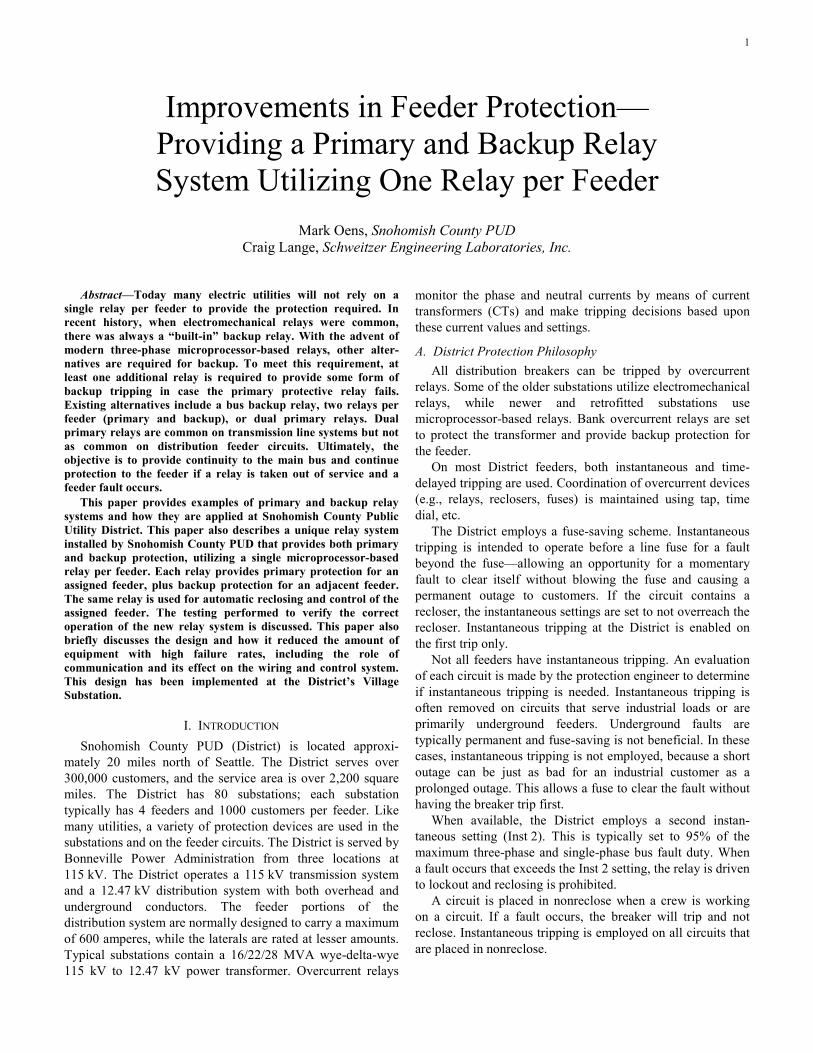
selected relay’s capabilities. The selected relay is very flexible. The relay has two sets of CT inputs and multiple numerical current measurements. The current measurements in each set include maximum phase, zero-sequence, and negative-sequence. Also, the relay allows each overcurrent measurement to be applied to different overcurrent elements. This flexibility allows for the two-breaker application used by the District. One set of CTs is dedicated to the primary breaker (Breaker 1) and the other set of CTs is dedicated to the adjacent breaker (Breaker 2). Three optional CT connections are shown in Figs. 4, 5, and 6. Table 1 shows the available measurement and overcurrents applied in Fig. 5. The CT circuits and trip circuits are daisy chained, so each relay is providing the primary protection for its associated breaker and backup protection for its adjacent breaker. The relay at the end of the switchgear protects the first breaker, as shown in Fig. 6.
TABLE 1 CT INPUTS AND OVERCURRENT ELEMENT ASSIGNMENTS
CT Set Measurement Application
Set 1 Max phase Breaker 1 phase time-overcurrent
Set 1 3I0 Breaker 1 ground time-overcurrent
Set 1 3I2 Breaker 1 negative-sequence time-overcurrent
Set 2 Max phase Breaker 2 phase time-overcurrent
Set 2 Max phase Breaker 2 ground time-overcurrent (torque controlled, see Fig. 10)
Relay 1
1 2
Fig. 5. Primary Protection for Breaker 1 and Backup Protection for Breaker 2
Relay 1
1
Relay 2
2
Relay 3
3
Fig. 6 Daisy Chained CT Connection and Protection
B. Front-Panel Target Design The District was very concerned about the behavior of the
front-panel targets on the selected relays. Specifically, the District did not want backup overcurrent target LEDs to appear on the front panel of the relay unless the relay actually initiated a backup trip for the adjacent breaker. The backup overcurrents are set with a slightly higher pickup and longer time lever than the primary. An example of phase time-overcurrent settings for Breaker 1 and backup settings for Breaker 2 is shown in Table 2.
TABLE 2 PRIMARY AND BACKUP TIME-OVERCURRENT
Relay Phase Pickup Time Dial, U4 Curve
Relay 2 primary 720 Amps primary 5.0
Relay 1 backup 840 Amps primary 7.8
C. Testing and Verifying Design The District built a test rack and implemented a procedure
of testing relays and related equipment prior to installation. Equipment and relays were tested thoroughly in the shop before a design was implemented or further equipment/relays were purchased. The objective was to discover the strengths and weaknesses of the equipment/relays, verify the design concept, and minimize problems encountered in the field.
1) Protection Testing The selected relay has two sets of CT inputs. The District
constructed a test rack similar to the circuit shown in Fig. 4. The first tests were to confirm the selectivity of the protection features. There was a high degree of emphasis placed on injecting fault current on the first set of CTs and having a trip signal being issued only for the corresponding breaker. There were several variations of these tests and a matrix was developed. Examples of these tests are in Tables 3–14 in the Appendix. Tables 3–11 show the primary protection testing completed, and Tables 12–14 show the backup protection testing completed.
There were some issues associated with the ground overcurrent element that had to be accepted by the District. In the past, the District feeder overcurrent relays had a neutral input where the CT residual current was injected into the relay

6
and actual current was measured. Only two sets of three CT inputs are available on the rear connections of the relay, so the PUD could not construct a CT neutral and connect to a single relay input, as was the usual practice. Therefore, the relay calculated the residual current (3I0) used by the ground overcurrent element. Another issue was related to the ground settings for the second set of CTs (backup ground overcurrent for the adjacent breaker). There was no direct operating quantity that could be used for the backup ground overcurrent element. Winding 2 maximum phase current is the only other measured quantity that could be applied. A combination of maximum phase overcurrent and torque control was required to create this element. A logic variable using zero-sequence current was used as a torque control to enable this element. This was extensively tested until the protection group was satisfied that there were no unwanted trip operations. See Fig. 10 and Table 1.
2) Relay Settings and Custom Logic Because the relay was not originally designed for this
application, some of the built-in functions could not be used and others had to be developed. The relay settings were advanced, so extra emphasis was placed on version control and developing a standardized settings template. The standard-ized settings template covered all settings contingencies, so only a few settings needed to be changed to modify the way the relay operates. A settings guideline was created to help the protection engineers and relay technicians understand the areas that would be changed. The use of communications for control also added a level of complexity.
Breaker 1 tripping and closing logic (Figs. 7–8) was fairly straightforward. The only issues were the nature of the indication from SCADA and the integrated pushbuttons. Both the pushbuttons and SCADA control were momentary, and timers were required to maintain the output contact long enough to assure correct breaker operation.
Timer With 10-Cycle Dropout
67 Inst 1 Ground
51 Ground51 Phase
51 Neg-Seq
67 Inst 1 Phase67 Inst 2 Ground67 Inst 2 Phase67 Inst 3 Phase
67 Inst 3 GroundUF
Timer With 10-Cycle Dropout
Pushbutton TripSCADA Trip
OUT 1Trip Breaker 1
Fig. 7. Breaker 1 Trip Logic
Pushbutton Close Breaker 1
SCADA Trip Other Internal
Relay Logic
OUT 4Close Breaker 1
Fig. 8 Breaker 1 Close Logic
Breaker 2 tripping and closing logic (Fig. 9) was also rather straightforward. The only issues were the use of the pushbuttons to trip and close the adjacent breaker and the logic to control the ground element. Breaker 2 zero-sequence current was used to torque control the ground overcurrent
element (Fig. 10). This was extensively tested until the protection group was satisfied that there would not be any unwanted trips.
Timer With 10-Cycle Dropout
51 Ground
51 Phase
Timer With 10-Cycle Dropout
Pushbutton Close Breaker 2
Other Internal
Relay Logic
Timer With 30-Second
Dropout
Pushbutton Enable Trip/Close
Pushbuttons Breaker 2
Pushbutton Trip Breaker 2
OUT 2Trip Breaker 2
OUT 5Close Breaker 2
Fig. 9. Breaker 2 Trip and Close Logic
Timer With 10-Cycle Dropout
Phase Time OC Element Curve Timing
Residual Ground Time OC Element Curve Timing
51 Phase PU
Imax2
51 Ground PU
Imax2
–
+Breaker 2 Zero-Seq
Inst Current Mag
51 Ground PU
Torque Control Switch
–
+
Torque Control
Switch = 1
–
+
Fig. 10. Breaker 2 Phase and Ground Tripping Logic
Breaker 1 reclose status had the same issues as tripping and closing, with the additional requirement that the relay retain knowledge of the position status through a power cycle. This was accomplished using built-in latch bits, which retain their status. Underfrequency tripping was desired at the breaker level. Unfortunately, this was not a built-in feature, but an underfrequency function was easily created using the built-in relay logic. Automatic reclosing was required only for Breaker 1. Testing to confirm reclosing times and appropriate breaker recloses was completed. Typical reclosing times are 5 or 10 seconds. See Tables 6–11.
The District uses three instantaneous settings—Inst 1, Inst 2, and Inst 3. Inst 1 settings are used for fuse saving. Inst 3 settings are enabled when the relay is in nonreclose. Inst 1 and Inst 3 tripping are enabled on the first trip only. Inst 1 and Inst 3 are disabled for four seconds after the breaker is closed for cold load pickup. See Fig. 11.
50 Ground Settings
IG
–
+
Torque Control Switch
50 Phase Setting –
+
Inst 1 Ground
Reclose Enable
Timer With 4-Second
Pickup52A (Breaker 1 Status)
Inst 1 PhaseIABC
Torque Control Switch
Fig. 11. Inst 1 Trip Logic
7
50 Ground Inst 2
IG
Set to 2LL Positive-Sequence Current
Positive-Sequence Instantaneous Current
–
+
Torque Control Switch = 1
50 Phase Inst 2
IABC
–
+
Torque Control Switch = 1
If 3LG > 1LG
–
+
67 Inst 2 Ground – Drive to Lockout
67 Inst 2 Phase – Drive to Lockout
Fig. 12. Inst 2 Trip Logic
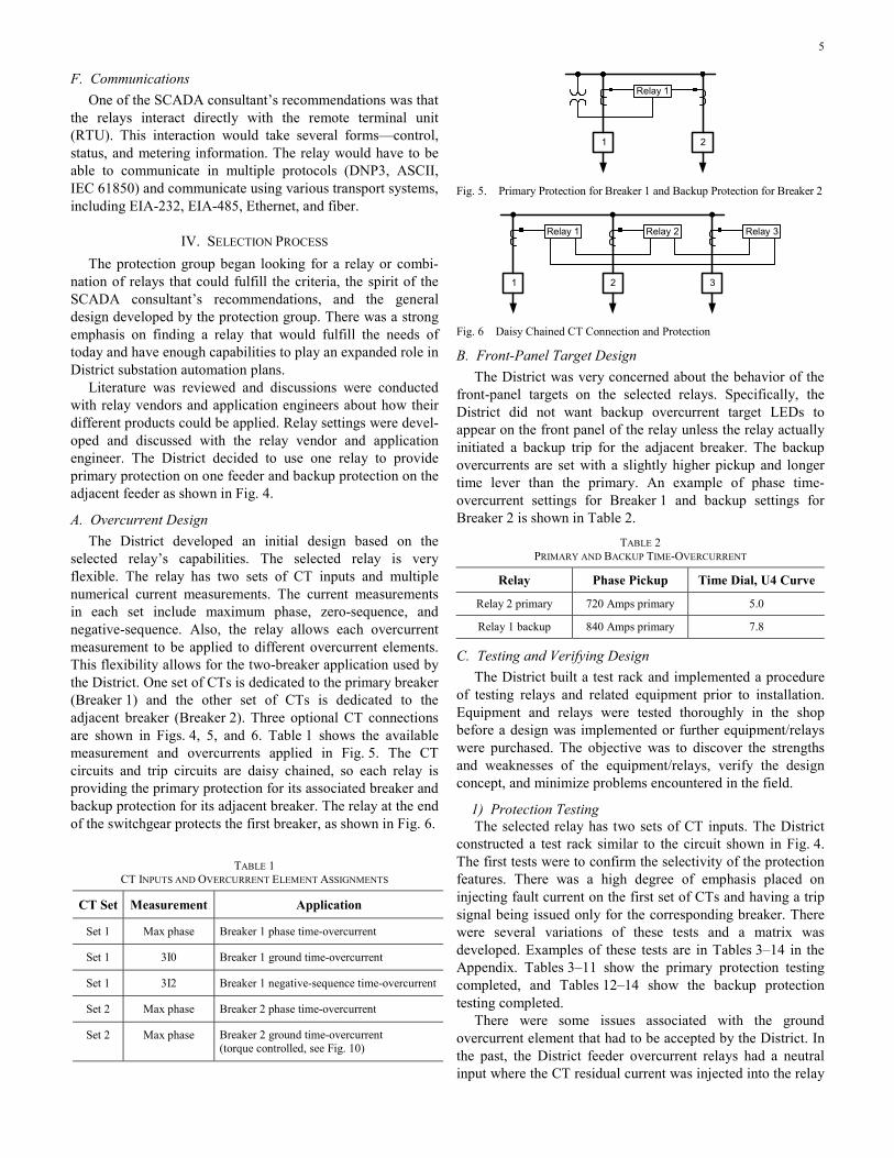
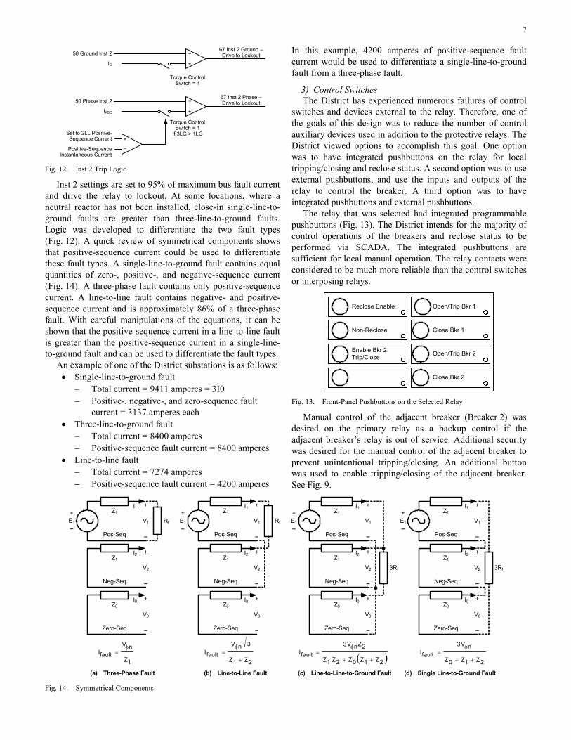
Inst 2 settings are set to 95% of maximum bus fault current and drive the relay to lockout. At some locations, where a neutral reactor has not been installed, close-in single-line-to-ground faults are greater than three-line-to-ground faults. Logic was developed to differentiate the two fault types (Fig. 12). A quick review of symmetrical components shows that positive-sequence current could be used to differentiate these fault types. A single-line-to-ground fault contains equal quantities of zero-, positive-, and negative-sequence current (Fig. 14). A three-phase fault contains only positive-sequence current. A line-to-line fault contains negative- and positive-sequence current and is approximately 86% of a three-phase fault. With careful manipulations of the equations, it can be shown that the positive-sequence current in a line-to-line fault is greater than the positive-sequence current in a single-line-to-ground fault and can be used to differentiate the fault types.
An example of one of the District substations is as follows: • Single-line-to-ground fault
− Total current = 9411 amperes = 3I0 − Positive-, negative-, and zero-sequence fault
current = 3137 amperes each • Three-line-to-ground fault
− Total current = 8400 amperes − Positive-sequence fault current = 8400 amperes
• Line-to-line fault − Total current = 7274 amperes − Positive-sequence fault current = 4200 amperes
In this example, 4200 amperes of positive-sequence fault current would be used to differentiate a single-line-to-ground fault from a three-phase fault.
3) Control Switches The District has experienced numerous failures of control
switches and devices external to the relay. Therefore, one of the goals of this design was to reduce the number of control auxiliary devices used in addition to the protective relays. The District viewed options to accomplish this goal. One option was to have integrated pushbuttons on the relay for local tripping/closing and reclose status. A second option was to use external pushbuttons, and use the inputs and outputs of the relay to control the breaker. A third option was to have integrated pushbuttons and external pushbuttons.
The relay that was selected had integrated programmable pushbuttons (Fig. 13). The District intends for the majority of control operations of the breakers and reclose status to be performed via SCADA. The integrated pushbuttons are sufficient for local manual operation. The relay contacts were considered to be much more reliable than the control switches or interposing relays.
Reclose Enable Open/Trip Bkr 1
Non-Reclose
Enable Bkr 2Trip/Close
Close Bkr 1
Open/Trip Bkr 2
Close Bkr 2
Fig. 13. Front-Panel Pushbuttons on the Selected Relay
Manual control of the adjacent breaker (Breaker 2) was desired on the primary relay as a backup control if the adjacent breaker’s relay is out of service. Additional security was desired for the manual control of the adjacent breaker to prevent unintentional tripping/closing. An additional button was used to enable tripping/closing of the adjacent breaker. See Fig. 9.
Pos-Seq
V1
I1Z1
E1 Rf
+
–
+
Neg-Seq
V2
I2Z1
+
–
Zero-Seq
V0
I0Z0
+
–
Pos-Seq
V1
I1Z1
E1 Rf
+
–
+
Neg-Seq
V2
I2Z1
+
–
Zero-Seq
V0
I0Z0
+
–
Pos-Seq
V1
I1Z1
E1
3Rf
+
–
+
Neg-Seq
V2
I2Z1
+
–
Zero-Seq
V0
I0Z0
+
–
Pos-Seq
V1
I1Z1
E1
+
–
+
Neg-Seq
V2
I2Z1
+
–
Zero-Seq
V0
I0Z0
+
–
–– ––
(a) Three-Phase Fault (b) Line-to-Line Fault (d) Single Line-to-Ground Fault(c) Line-to-Line-to-Ground Fault
3Rf
2Z1Z0Z
nV3
faultI++
φ=
2Z1Z
3nV
faultI+
φ=
1Z
nV
faultIφ
= ( )2Z1Z0Z2Z1Z
2ZnV3
faultI++
φ=
Fig. 14. Symmetrical Components

8
4) Breaker Indication and Reclose Status Indication of breaker and reclose status was also needed.
Indication could be integrated in the relay or external lights could be used. The District chose to use the integrated lights on the relay and a set of external lights for breaker status. This enabled a crew to establish the breaker status immediately upon entering the switchgear. The integrated lights on the relay were sufficient for local indication of reclose status.
5) Target Information When the District began to install microprocessor-based
relays, the crews had to interact more with the relay to obtain fault information (type, fault current, etc.). There was a desire to simplify the target information on the front of the relay so crews could easily identify the type of fault without scrolling through the relay screens. The relay was programmed to display the type of fault and notify if the relay tripped Breaker 1 or 2 (Fig. 15).
TargetReset
Enabled
Trip
Inst-1 or 3
Time
Inst-2
UF
Neg-Seq
79 Reset
79 Cycle
79 Lockout
Bkr 1 A Fault
Bkr 1 B Fault
Bkr 1 C Fault
Bkr 1 Gnd Fault
LOP
Bkr 2 Phase
Bkr 2 Ground
Fig. 15. Front-Panel Targets Available on the Selected Feeder Relay
6) Communications Part of the design strategy was to reduce the amount of
wiring and use communications for metering and control. DNP3, transmitted over EIA-485 (two-wire), was selected as the communications protocol and method because of the capabilities of both the relay and the RTU.
Several days were committed to understanding how the RTU, relay, meter, and annunciator communicated via DNP3. Issues such as communications mode, preconditioning, postconditioning, multipliers, and dead bands were tested.
All communications values are in reference to Breaker 1 (the primary breaker/protection). Analog information being provided by the relay is IA, IB, IC, VA, VB, VC, three-phase MW, and three-phase MVAR (Breaker 1 only). Binary information being provided by the relay is 52A (Breaker 1), reclose status, underfrequency trip, and relay alarm. Controls done via communications for Breaker 1 are trip/close and reclose/nonreclose.
7) Metering and Displays The District uses meters to capture data for planning and
optimization. These meters were necessary, but their displays and interaction to the RTU could be removed. It was decided
to use the display of the relay for local metering quantities. This eliminated the need for the meter transducer and display.
8) Automated Protection Testing Procedures The automated software used to test the relays did not have
a module for the relay that was used. A new module and testing procedures were developed during this time frame. Testing procedures were developed to encompass the new design.
D. Field Implementation The field implementation of the protection settings went
smoothly, and a great deal of the credit for the smooth transition goes to the testing done in the shop. There were a few minor setbacks but nothing that would be considered major.
One challenge was that the first three outputs of the relay are polarity sensitive. Initial output contact assignments were as follows:
• OUT 1 trip Breaker 1 • OUT 2 close Breaker 1 • OUT 3 trip Breaker 2 • OUT 4 close Breaker 2
The District uses dc trip and ac closing. Therefore, the first three outputs could only be used for tripping. The District standardized on the following contact assignment:
• OUT 1 trip Breaker 1 • OUT 2 trip Breaker 2 • OUT 3 not used • OUT 4 close Breaker 1 • OUT 5 close Breaker 2
Another challenge was the equation for the time-overcurrent curve. It was changed from the traditional equation to more closely mimic the extremely inverse curve. This was not caught in testing because the testing times were derived directly from the equation. The automated software used to test the relays used the older equation. Once the software was updated with the correct equation, the issue was resolved.
There were a couple of minor settings changes made to make the pushbuttons and metering display more consistent with other substations in the system.
The communications aspects of this project had a few more problems. During the testing, there were a limited number of relays (two) connected on the EIA-485 (two-wire) network. Field implementation initially had six relays, an annunciator, and a meter on one EIA-485 (two-wire) network. This proved to be problematic so the relays were moved to their own EIA-485 (four-wire) network. The increased number of relays on the EIA-485 network required more testing and configuration changes than expected. Control, analogs, and binary information response times are meeting expectations. Further testing is being done to enhance the response time. The meter and annunciator were less reliable and were moved to different networks.

9
V. CONCLUSION The District believes that this new design improves the
overall reliability of their protective relay systems. A basic review of fault tree analysis would show that a reduction of individual parts improves availability of the District’s relay system. The total number of individual parts installed on the panel has been significantly reduced. The external control switches that were problematic were removed from the design. The selected relays are relatively new, but the overall reliability of relays from this manufacturer has been excellent. The number of drawings was also reduced significantly, resulting in less wiring errors by the switchgear manufacturer.
This project was considered successful in a variety of ways. The in-shop testing proved to be a most valuable tool. Problems could be discovered and overcome, theories could be tested, and design decisions could be made with confidence
and buy-in from all parties. Very few protection problems were encountered during commissioning, and those were easily overcome.
The ability to maintain primary and backup protection was considered essential to the District. Equipment with higher failure rates was removed from the system. Quality communi-cations are available for metering, binary inputs, and control.
This system is in place at the District’s Village Substation and is the standard approach for the next five substations and two retrofit substations. The cost of this approach was approximately equivalent to the previous design. This approach should prepare the District for future automation projects, SCADA upgrades, and the retrieval of information. This project went so smoothly that most of the District management were unaware of the design changes and technical advancements made at Village Substation.
VI. APPENDIX TABLE 3
BOTH BREAKERS CLOSED TEST
Breaker Trip Input Quantity 1 2 Target Lights Notes
Inst 1 Ground 600 Amps Yes No OK
Inst 2 Ground 4000 Amps Yes No OK Relay goes to LO
Inst 2 Ground 6000 Amps Yes No OK Relay goes to LO
Inst 3 Ground 600 Amps Yes No OK
Inst 1 Phase 1200 Amps Yes No OK
Inst 2 Phase 5000 Amps Yes No OK Relay goes to LO
Inst 3 Phase 1200 Amps Yes No OK
OC Ground Various Amps Yes No OK
OC Phase Various Amps Yes No OK
OC Neg-Seq Various Amps Yes No OK
UF UF 59.3 Freq Yes No OK Relay goes to LO
TABLE 4 BOTH BREAKERS WITH LOAD ON BREAKER 2
Breaker Trip Input Quantity 1 2 Target Lights Notes
Inst 1 Ground 600 Amps Yes No OK
Inst 2 Ground 4000 Amps Yes No OK Relay goes to LO
Inst 2 Ground 6000 Amps Yes No OK Relay goes to LO
Inst 3 Ground 600 Amps Yes No OK
Inst 1 Phase 1200 Amps Yes No OK
Inst 2 Phase 5000 Amps Yes No OK Relay goes to LO
Inst 3 Phase 1200 Amps Yes No OK
OC Ground Various Amps Yes No OK
OC Phase Various Amps Yes No OK
OC Neg-Seq Various Amps Yes No OK
UF UF 59.3 Freq Yes No OK Relay goes to LO

10
TABLE 5 BREAKER 2 OPEN
Breaker Trip Input Quantity 1 2 Target Lights Notes
Inst 1 Ground 600 Amps Yes No OK
Inst 2 Ground 4000 Amps Yes No OK Relay goes to LO
Inst 2 Ground 6000 Amps Yes No OK Relay goes to LO
Inst 3 Ground 600 Amps Yes No OK
Inst 1 Phase 1200 Amps Yes No OK
Inst 2 Phase 5000 Amps Yes No OK Relay goes to LO
Inst 3 Phase 1200 Amps Yes No OK
OC Ground Various Amps Yes No OK
OC Phase Various Amps Yes No OK
OC Neg-Seq Various Amps Yes No OK
UF UF 59.3 Freq Yes No OK Relay goes to LO
TABLE 6 RECLOSE ENABLED—BOTH BREAKERS CLOSED
Breaker Trip
Input Quantity 1 2 Target Lights Notes
Inst 1/OC Ground 600 Amps/Various Yes/Yes No/No OK
Inst 1/OC Phase 1200 Amps/Various Yes/Yes No/No OK
TABLE 7 RECLOSE ENABLED—BREAKER 2 WITH LOAD CURRENT
Breaker Trip
Input Quantity 1 2 Target Lights Notes
Inst 1/OC Ground 600 Amps/Various Yes/Yes No/No OK
Inst 1/OC Phase 1200 Amps/Various Yes/Yes No/No OK
TABLE 8 BREAKER 2 OPEN
Breaker Trip
Input Quantity 1 2 Target Lights Notes
Inst 1/OC Ground 600 Amps/Various Yes/Yes No/No OK
Inst 1/OC Phase 1200 Amps/Various Yes/Yes No/No OK
TABLE 9 BOTH BREAKERS CLOSED
Breaker Trip
Input Quantity 1 2 Target Lights Notes
Inst 3/OC Ground 600 Amps/Various Yes/Yes No/No OK Relay does not reclose
Inst 3/OC Phase 1200 Amps/Various Yes/Yes No/No OK Relay does not reclose
TABLE 10 BOTH BREAKERS CLOSED AND LOAD CURRENT ON BREAKER 2
Breaker Trip
Input Quantity 1 2 Target Lights Notes
Inst 3/OC Ground 600 Amps/Various Yes/Yes No/No OK Relay does not reclose
Inst 3/OC Phase 1200 Amps/Various Yes/Yes No/No OK Relay does not reclose

11
TABLE 11 BREAKER 2 OPEN
Breaker Trip
Input Quantity 1 2 Target Lights Notes
Inst 3/OC Ground 600 Amps/Various Yes/Yes No/No OK Relay does not reclose
Inst 3/OC Phase 1200 Amps/Various Yes/Yes No/No OK Relay does not reclose
TABLE 12 BACKUP PROTECTION WITH BOTH BREAKERS CLOSED
Breaker Trip
Input Quantity 1 2 Target Lights Notes
OC Ground Various Amps No Yes OK Breaker 2 does not reclose
OC Phase Various Amps No Yes OK Breaker 2 does not reclose
TABLE 13 BACKUP PROTECTION—BOTH BREAKERS CLOSED WITH LOAD CURRENT ON BREAKER 1
Breaker Trip
Input Quantity 1 2 Target Lights Notes
OC Ground Various Amps No Yes OK Breaker 2 does not reclose
OC Phase Various Amps No Yes OK Breaker 2 does not reclose
TABLE 14 BACKUP PROTECTION—BREAKER 1 OPEN
Breaker Trip
Input Quantity 1 2 Target Lights Notes
OC Ground Various Amps No Yes OK Breaker 2 does not reclose
OC Phase Various Amps No Yes OK Breaker 2 does not reclose
VII. REFERENCES [1] D. Backholm, PE, “Electric Distribution System Protection Engineering
Guidelines,” Snohomish County PUD No. 1, Everett, WA, 2003. [2] J. Lewis Blackburn, Symmetrical Components for Power Systems
Engineering, New York: M. Dekker, 1993.
VIII. BIOGRAPHIES Craig Lange received his BS in electrical engineering from Washington State University in 1973. He is currently employed by Schweitzer Engineering Laboratories, Inc. as a field application engineer, providing customer support and training. Prior to his employment at SEL, Craig was employed by Puget Sound Energy for 25 years, performing both design and daily operation of protective relay and substation control systems.
Mark Oens received his BS in electrical engineering from Washington State University in 1992. He worked for Pacific Northwest Laboratories (Battelle) from 1992 through 1995, where he did energy-related research. In 1995, he joined Snohomish County PUD, where, for the last 8 years, he has been working in the System Protection department. He is a member of IEEE, a registered professional engineer in the state of Washington, and serves on the Western Power Delivery Automation Committee.
© 2006 by Snohomish County PUD and Schweitzer Engineering Laboratories, Inc. All rights reserved.
20060913 • TP6246-01