improved mechanical properties of alloy 718 by anneal ii
TRANSCRIPT

Improved Mechanical Properties of Alloy 718 by Anneal and Direct Aging Process for Nuclear Fusion Applications
II Soon Hwang, Ronald G. Ballinger, Martin M. Morra, Benjamin Tao, and Salim Mathew*
Departments of Materials Science and Engineering and Nuclear Engineering Massachusetts Institute of Technology
Cambridge, Massachusetts 02139
Abstract
A triple-melt alloy 718 is being used for high strength fasteners on a tokamak fusion reactor that is being constructed at MIT on behalf of U.S. DOE. The fastener is designed for up to 910 MPa tensile stress at 77 K with alternating load during a pulsed magnet operation between 0 and 9 tesla. Manufacturing malpractice for the fastener prompted an interim evaluation which revealed poor fracture toughness (less than 110 MPam) of the direct aged material containing a microstructure of about 10 ym grain size with the preponderance of coarse delta phase, Ni3Nb. An anneal and direct aging was chosen to improve the fracture toughness based on favorable experience with similar high temperature treatments. Due to the large thickness of the fastener and the requirement for high strength a fine adjustment of annealing temperature was necessary. A 1,050 C for one hour anneal followed by a standard direct aging was selected for complete removal of undesirable precipitates while grain size increased to about 70 pm. A fast cooling by forced air convection was used to avoid re-precipitation of Laves or delta phases. Yield strength and ultimate tensile strength of the anneal and direct aged material at room temperature were decreased by about 8 % compared with those of the direct aged condition. Fracture toughness was increased by as much as 100 % and fatigue crack growth rate was reduced by a factor of three. The improvement is attributed to the removal of coarse precipitates which presumably are reused as gamma double prime precipitates in the matrix. The anneal and direct aging is hence recommended for low temperature applications including fusion reactor superstructure.
*Visiting student from Baylor College
Superalloys 718,625 and Various Derivatives Edited by Edward A. Loria
The Minerals, Metals & Materials Society, 1991
621
Tokamak Fusion Device and Allov 718 At the Plasma Fusion Center of MIT, an experimental nuclear fusion device,
Alcator C-MOD, is being constructed with the support of DOE’s Magnetic Fusion Program. Alcator C-MOD is essentially a large donut-shaped vacuum chamber surrounded by high field Bitter magnets. During operation, a high density hydrogen plasma will be compressed by magnetic pressure to induce nuclear fusion. Large Lorentz forces will be exerted to twist and expand the magnet unless a rigid structure is built around to hold the Bitter magnet at 77 K. The magnetic pressure at 9 tesla corresponds to about 80 MPa which is about five times that of a pressurized water reactor.
For the structural support, a cylindrical pressure vessel, and top and bottom cover plates have been fabricated of Type 316 LN stainless steel. Each forged piece weighs about 15 tons and does not contain any weld. Fastening of top and bottom plates to the cylindrical vessel is made by 96 fasteners. The superstructure with the fasteners that have threads at one end and a paddle section with pinhole at the other end are shown in Figure 1. Each fastener, called a drawbar, carries a peak load of 250 tons at 9 tesla field at 77 K. This corresponds to a peak tensile stress of 910 MPa. The choice for the drawbar material requiring high strength has been made to be alloy 718 that is a nickel base superalloy strengthened by fine y (NigNb) precipitates [l].
Figure 1. A Sketch of Alcator C-MOD Superstructure.
Initial Soecifications on Allov 718 A triple melt alloy 718 with a direct age condition was selected initially for the
high strength and good ductility which are proven by recent aerospace applications [2,3]. The alloy 718 contains 52.8Ni-18.6Cr-5.5Nb-3.1 MO-1 .lTi-0.5-AI-0.2Co-0.04C with balance Fe. A minimum yield strength of 1,241 MPa with 12% elongation was specified for the mechanical property requirements at room temperature. During forging process, however, both die-failures and undersized stock material problems were encountered which prompted a holding of manufacturing process and an interim property evaluation. Specimens were made and given direct aging for tensile and fracture tests at room temperature.
A significant portion of tensile test specimens did not meet the yield strength requirement. Fracture toughness was even less satisfactory ranging from 73 to 109 MPa resulting in a minimum critical crack size of only 2.7 mm. Although the superstructure including the drawbars is accessible for periodic inspections, a
622

concern was raised for possibly extensive downtime. Hence a new emphasis was placed on the higher fracture toughness. Given the variability in strength between drawbars, presumably caused by manufacturing malpractices, it was decided to tolerate up to 15% decrease in yield strength at room temperature. Subsequent refinement of the drawbar stress analysis increased the strength margin. Microstructural analysis of drawbars showed a small grain size with preponderance of coarse precipitates. Coarse precipitates are often introduced to maintain fine grains during high temperature processes for the direct aged material [3].
Develooment of Anneal and Direct Aaina Process An obvious direction of change was the use of solution anneal to increase
grain size, and hence ductility, prior to aging. A high temperature solution annealing and aging, as specified by Aerospace Materials Specification 5664 [4] which gives a minimum yield strength of 1,034 MPa , was selected as a suitable procedure. AMS 5664 uses 1 hour annealing at 1,066 C. The high temperature annealing and aged condition was developed for an improved resistance to hydrogen assisted cracking at lower temperatures. Mills [5] and Logsdon et al. [6] showed increased toughness and decreased strength by the annealing step. Despite the strength decrease, the fatigue crack growth rate of the annealed and aged condition‘ is equivalent or sometimes better than the conventional heat treatment which has an initial annealing at temperature just below Laves-phase solvus before the aging [6]. But both Iow- cycle fatigue life and notch stress-rupture life at high temperatures are decreased by about a factor of two by the annealing and aging process [7,8]. These disadvantages occurring at high temperatures were not issues with the drawbar operating between room temperature and 77 K.
Ootimal Processing There was a concern with excessive grain growth and softening by the high
temperature anneal process. Hence a fine tuning of anneal temperature is desired. The drawbar having about 10 cm diameter is expected to develop a large difference in time-at-solution-temperature between the surface and center. This may produce excessive grain growth near the surface which is heavily warm-worked during prior forging process. Accelerated grain growth due to prior plastic deformations is a well established phenomenon in alpha-brass and a nickel-base alloy [9,10]. Another concern with the thick section was the slow cooling process after annealing which may result in excessive delta and Laves precipitates upon cooling. At optimal temperature all delta and Laves phases will be dissolved with limited grain growth.
A temperature of 1,05OC, instead of 1,066C of AMS 5664 [4], was considered for limiting grain growth. Several metallographic specimens with about 1 cm3 size were given an hour annealing treatment at various temperatures between 1,035C and 1,066C. By this experiment, it was found that no grain growth takes place at solution temperature below 980C. Excessive grain growth was observed at 1 ,O66C, as
shown in Table 1. Hence a temperature of 1050 f83CC was selected as the optimum.
Table 1. Microstructure of Alloy 718 as Function of One-Hour Anneal Temperature.
Temperature(C) Gain Size (urn) Amount of precipitates As direct aged 10 preponderant 1,035 70 few but remains 1,050 67 none 1,066 110 none
623

Tighter over-temperature tolerance is specified to avoid excessive grain growth. Earlier experience with 1,050C annealing and aging by Prybylowski [ll] showed that fatigue crack growth rate is comparable to that of the conventional heat treatment condition while ductility is significantly increased. This provided a direct evidence that the lowered solution anneal temperature (1,050C) also provides similar advantages of AMS 5664.
In order to minimize microstructural difference across the relatively large section a thermal equalization was made at 968 C where no grain growth takes place. The second issue of cooling rate after the annealing was solved by employing a forced air cooling. Temperature histories were verified by a trial heat treatment with a 10 cm diameter and 200 cm length section which was the heaviest section of an actual drawbar. Temperatures at center and surface of the section were continually monitored by emplacing thermocouples during the cooling. It was found that the forced air cooling by far provided an adequate cooling rate to avoid the precipitates. The temperature history during the heatup and the forced air cooling following the completion of one-hour annealing is shown in Figure 2 of the TTT diagram for alloy 718 [12].
1200
800 2 ; 600 t E 400
0.001 0.01 0.1 1 10 100 Time (Hr)
Figure 2. Temperature Histories during Heat-up and Cool-down Periods of Annealing Treatment in Comparison with TTT Diagram for Alloy 718 (TCl and TC3 denote surface and center temperatures, respectively).
Based on the optimization experiments the annealed and direct aged (ADA hereafter) process is established as follows;
Heatup to 968 C and equalize for 20 min.
1050 +83cc for 1 hr in air Forced air cool to room temperature 720C for 8 hr Furnace cool at 55Clhr to 620C Hold at 620C for total 18 hr aging Air cool by natural convection.
624

bd I. C@ ‘5 up- 2 f6 i i
e ‘ 1 I’ / I 8
.‘! ;W>l
,- gHxk:* ’ c
Figure 3. Optical and SEM Micrographs for ADA and DA Conditions of Alloy 718.
625

N 0
R
M
2 THETA RIGAKU / USA
100
N 0
R M 80
60
40
20
0 .c 20.00 40.00 60.00 80.00 100.00 120.00
2 THETA RIGAKU / USA
Figure 4. X-ray Diffraction Spectra, Intensity vs. 20 (degree), of Extracted Phases for ADA (Upper Graph) and DA (Lower Graph) Conditions of Alloy 718.
626
Microstructure of ADA a d DA Optical and scan:ing electron micrographs of ADA and original direct aged
(DA hereafter) conditions are compared in Figure 3. ADA condition has about 70pm grain size with many twins whereas DA condition has about 1 Opm grain size. SEM micrographs show that grain boundaries are free of any precipitates in ADA unlike the DA. Coarse intragranular stringers which are (Ti,Nb) (C,N) are essentially unchanged by the ADA process, in agreement with observation made by Mills [5].
In order to identify phases present in DA and ADA conditions, precipitates were electrolytically extracted at a current density of 10 mA/cm2 in a 10% hydrochloric acid and 90% methanol solution. Filtered powders were examined by a Rigaku Model RU-300 X-ray diffractometer. X-ray diffraction spectra for ADA and DA precipitates are shown in Figure 4. In ADA, NbC is the only observed phase. In DA both delta (NigNb) phase and NbC are identified with the former being predominant. Energy dispersive X-ray (EDX) analysis of the precipitates of DA in both in-situ and extracted conditions showed that the chemistry of delta phase is Ni3Nb. Based on these observations the precipitates in DA, which are present predominantly along grain boundaries, were identified as delta (Ni3Nb) phase.
Mechanical Prooerties
Exoerimental Procedure Mechanical property measurements including tensile, fatigue and fracture
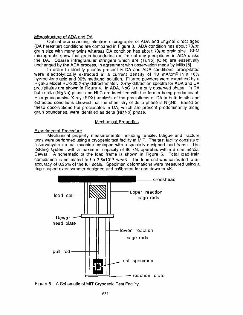
tests were performed using a cryogenic test facility at MIT. The test facility consists of a servohydraulic test machine equipped with a specially designed load frame. The loading system, with a maximum capacity of 90 kN, operates within a commercial Dewar. A schematic of the load frame is shown in Figure 5. Total load-train compliance is estimated to be 2.6x10⁻⁵ mm/N. The load cell was calibrated to an accuracy of 0.25% of the full scale. Specimen deformations were measured using a ring-shaped extensometer designed and calibrated for use down to 4K.
Dewar A head plate
pull rod
- lower reaction
cage rods
~ test specimen
e reaction plate
Figure 5. A Schematic of MIT Cryogenic Test Facility.
627

Two tensile specimen designs were used, as shown in Figure 6. Both fiat specimen and round bar specimen were used for ADA and DA although the majority of tests were made with the latter specimen design. The specimens were oriented with the loading axis parallel to the drawbar loading axis. All tests were load- controlled at 22.2Nkec using an extensometer with 12.7 mm gauge-length.
0.500
0.350
THREAD
Figure 6. Flat and Round Bar Specimen Designs for Tensile Tests (Dimensions in inches).
.250 dia.
Figure 7. A Compact Tension Specimen Design Modified for Both Fatigue and Fracture Toughness Tests of Alloy 718 (Dimensions in inches).
628

Both fatigue and fracture toughness tests were made using the same specimen, as shown in Figure 7. The 12.7mm thick compact tension specimen, recommended in ASTM E813-88, was modified to shorten the initial machined notch depth from 0.5 to 0.35 in terms of a/w. The modification allows more material for fatigue data acquisitions prior to the fracture toughness test which was started at a/w of about 0.65. Constant AK fatigue tests were performed with a 10 HZ sine wave and stress ratio(Pmax/Pmin) of 0.1 under computer control. The maximum value of K for the final fatigue tests was kept at 33 MPa or lower. Crack length was determined by an unloading compliance technique with the ring-shaped crack opening displacement gauge mounted at the load-line [13].
Fracture toughness was measured using the J-integral method in accordance with ASTM E813-88. Tests were run under crack opening displacement control with a typical rate of 0.1 mmlmin. The slower rate was based on the recommendations for cryogenic testing [14]. Data analysis was in accordance with ASTM El 152-87. Good data agreement and reproducibility ( within 5 %) by the toughness test system was found for a range of structural materials when results were compared with reliable data on the same materials, including those used for round-robin programs [151.
Tensile Prw Room temperature data from tensile tests on ADA and DA specimens are
compared in Table 2. For both flat specimen and round bar specimen, a consistent trend is observed: yield and ultimate tensile strengths are decreased, and ductility is increased by ADA. For the flat specimen design, only two specimens for each condition were tested whereas more than ten specimens were tested for the round bar specimen. Hence, statistics are significantly more meaningful for the latter case. About an 8% decrease in strength and 33% increase in elongation are observed by the ADA process based on the round bar test data.
Table 2. Tensile Properties of ADA and DA Conditions of Alloy 718.
Property
Flat Soecimen Yield Strength, MPa 1171 z!z 15 Ultimate Tensile Strength, MPa 1440+0 Elongation, % 18.6 + 1.6 Reduction of Area, % 28.4 + 1.2
Round Bar Soecimen* Yield Strength, MPa 1179 * 75** Ultimate Tensile Strength, MPa 1389 + 66** Elongation, % 20 I!I 6** Reduction of Area, % 47 z!z 6**
DA lmorovement (%l
1288 -9.1 1485+9 -3.0 11.5+ 1.6 61.7 27.1 It 0.1 4.8
1282+ 138 -8.0 1520+87 -8.6
15+5 33.3 30* 11 56.7
* Data of DA Condition was obtained by the drawbar manufacturer as a part of a quality assurance program [16].
** Error corresponds to three standard deviation (99.9% confidence level).
Interestingly, the results from flat specimen showed little difference in the reduction of area between ADA and DA materials, as shown in Table 2. Since the elongation is increased by a nearly similar degree as the round bar design, the discrepancy may be attributed to the formation of Luder’s band at 45O to the loading axis. Hence the measurement of cross sectional area by micrometer tends to
629

underestimate the reduction of area. In the round bar specimen design, the Liider’s band forms inward and results in a symmetric deformation at the neck. Hence the reduction of area data from the flat specimens, in particular, is considered to be less accurate.
Fatiaue Crack Growth Rate Fatigue crack growth rates of DA and ADA conditions are summarized in
Figure 8. Also compared in the graphs is the data obtained by the drawbar manufacturer for the DA condition as a part of quality assurance program. It is shown that the ADA condition has about a three times lower crack growth rate than the DA, for a AK range between 15 and 35 MPam at room temperature. The error on crack growth rate is shown for data of a typical specimen, as shown in Figure 8. At low AK’s, the factor of three difference in crack growth rate is not significant compared with the measurement error. But for AK of 25 MPam and higher the difference is more than two standard deviations of the measured crack growth rate. Hence the improvement in fatigue resistance is believed to be real and significant.
0.01
0.001
0.01
z- E 0.001
2 E lo-4
Y
lo-6
! 718 DA (R=O.l$ !
- . . . . . . . . . . . . . . . . . . . . . . . . . . . . . . . . . . . . . . . . . . . . . . . . . . . . . . . . . . . . j. . . . . . . . . . . . .._______...............~ ._._______ ,I j
#---- . . . . . . . . . . . . . . . . . . . . . . . .
20 30 40 50 60 AK (MPadm)
! 718 ADA (Rz0.1) 1
,-------------...------------
, 1 1 1
20 30 40 50 60 AK (MPadm)
Figure 8. Fatigue Crack Growth Rate of DA and ADA Conditions of Alloy 718 as Function of AK at 10 Hz with a Stress Ratio of 0.1.
630

A few tests were made at lower temperatures including 77 and 4K as shown in Figure 8. For ADA condition, the crack growth rate is decreased by about a factor of two between 293 and 4K. But no difference was observed between 293 and 77 K. Only one test was made at 77 K for DA. No change in crack growth rates between 293 and 77 K is observed, as shown in Figure 8.
Fracture Toughness Fracture toughness measured for ADA condition by J-integral technique is
summarized in Table 3. Data for DA condition is compared. DA condition was too brittle to be tested by the J-integral technique and the plane strain fracture toughness technique (ASTM E399) was employed. In Table 3, three test data points for ADA and more than ten data points for DA are summarized. The improvement in fracture toughness is as much as 95.5 % that is more than ten times the measurement error involved in the techniques.
Table 3. Fracture Toughness of Alloy 718 in ADA and DA Conditions.
Temperature (K\ 293
4
ADA* 172+5
DA** 88 z!I 20
58
Improvement (%) 95.5
* ASTM E813, J-integral Method ** ASTM E399, Plane Strain Fracture Toughness Test Method
At 4K one DA specimen tested shows about the same fracture toughness as those at room temperature. The low temperature dependence of mechanical properties including fracture toughness is in agreement with earlier observations on Alloy 718 by Tobler [17]. Since solid solution strengthening is governed by highly temperature-dependent diffusion rates, this is a good indication that the solute mechanism is not a large contributor to the superalloy strength. Similar behaviors were observed in other superalloys including JBK-75 [I 81 and lncoloy 908 [I 91.
Discussion
By the anneal and direct aging process the fracture toughness of alloy 718 is improved by about a factor of two and fatigue crack growth rate is decreased by about a factor of three compared with a direct aged material. It is a dramatic improvement in fracture toughness achieved at the expense of only an 8% decrease in yield strength and ultimate tensile strength.
Microstructural examination shows that the grain size is increased from 1Oym for the direct aging to 60pm for the anneal and direct aging. The small change in yield strength with the significant grain growth suggests that the dissolution of grain boundary precipitates, delta phase, may have been utilized in matrix as fine y” precipitates. This could possibly compensate the large strength reduction by the grain coarsening in the anneal and direct aging.
The dissolution of coarse delta phase near grain boundaries during the anneal played a primary role in the toughness increase. The inverse relationship between coarse precipitates/inclusions and toughness has been well established for various structural materials and welds [20]. Coarse precipitates are considered to initiate cracks more easily by either fracture of themselves or by decohesion of the interface between surrounding matrix.
An interesting observation made in this study is that the fatigue crack growth rate is also decreased by removing the delta phase. Usually the fatigue crack growth
631
rate is inversely proportional to yield strength and hence an increase in the crack growth rate in the anneal and direct aging would be expected 1211. The discrepancy suggests that in the direct aging condition the fatigue crack growth rate was increased significantly by the presence of delta phase. Hence the removal of delta phase overshadowed the effect of strength decrease on the fatigue properties.
Most of the tests were made at room temperature. A few tests at 77 and 4K indicates that the fatigue crack growth rate decreases at 4K. Due to an insufficient number of specimens tested at low temperatures, however, further work is necessary to substantiate the observed trend.
Conclusions
1. Anneal and direct age (ADA) process has been established for alloy 718 as an improved procedure for room temperature and cryogenic applications, as follows:
Annealina at 1050°C Heat-up to 938°C and equalize for 20 min.
Heat-up to 1050 f:zand hold 1 hour. Cool to room temperature by forced air convection.
Aaina Heat up to 720°C and hold for 8 hours. Cool to 620 at 55”C/hr in furnace. Hold at 620 for total aging time of 18 hours. Cool by natural air convection.
2. The ADA process resulted in the grain coarsening to 70pfn in diameter, and the dissolution of coarse delta phase from grain boundary area which were present in a direct aged (DA) material with 10p~m grains. Tensile strength decreased by 8% from DA condition. As much as a 96 % increase in fracture toughness and a 60 % increase in reduction of area are achieved. Fatigue crack growth rate was decreased by about a factor of three. It is suggested that the dissolved delta phase may have been beneficial not only for the toughness improvement but maintaining tensile properties by producing more gamma double prime precipitates in matrix.
Acknowledgement
The authors would like to express their appreciation for both the technical and administrative support of Drs. David Gwinn, Herbert Becker and Mr. Edward Thibeault of the MIT Plasma Fusion Center. This work has been supported by the MIT Plasma Fusion Center.
References
1. Ballinger, R.G., Becker, H.D., Hwang, I.S., Titus, P., Fisher, K., and Weber, K., “Superstructure for Super Tokamak: Alcator C-MOD,” Proc. the 73th /EEE Symposium on Fusion Engineering, Knoxville, Tennessee, pp. 1367-I 370, 1989
2. Montano, J.W., “A Mechanical Property and Stress Corrosion Evaluation of VIM- ESR-VAR Work Strengthened and Direct Double Aged lnconel 718 Bar Material,” NASA Technical Paper 2634, 1986
3. Krueger, D.D., Proc. Symposium on Alloy 778, Loria, E., Ed., Pittsburgh, Pennsylvania, p. 279, 1989
632

4. Aerospace Materials Specification 5664, Society of Automobile Engineers, 1987
5. Mills, W.J., “Fracture Toughness Variation for Alloy 718 Base Metal and Welds” Proc. Srmposium on Alloy 778, Loria, E., Ed.,Pittsburgh, Pennsylvania, 1989
6. Logsdon, W.A., Kossowsky, R. and Wells, J.M. paper C-4, Advances in Cryogenic Engineering, Vol.24, pp.1 97-209, 1977
7. Merrick, H.F. “Low Cycle Fatigue of Three Wrought Nickel-base Alloys”, Met. Trans. Vol.5, pp. 891-897, 1974
8. Muzyka, D.R. and Maniar, G.N., Metals Eng. Quarterly, pp. 23-37, 1969
9. Kwun, S.I. and Park, S.H., Scripta Met., Vol. 21, p. 797, 1987
10. Ballinger, R.G. and Hwang, I.S., “Characterization of Microstructures and IGSCC of Alloy 600 Steam Generator Tubing,” Final Report of EPRI Project S303-10 and S303-26, EPRI, Palo Alto, California, in press
11. Prybylowski, J.W., Ph.D. Thesis, MIT, Cambridge, Massachusetts, 1986
12. Eiselstein, ASTM STP No. 369, pp. 62-79, 1965
13. Saxena, A. and S.J. Hudak, Jr., “Review and Extension of Compliance Information for Common Crack Growth Specimens,” international Journal of Fracture, Vol. 14, no. 5, pp. 453-468, 1978
14. Tobler, R.L., “Proposed ASTM Standard E813 Annex for Tests in Liquid Helium,” presented at ASTM Symposium on Elastic-Plastic Fracture Mechanics, Bueno Vista, Florida, Nov. 1989
15 Hwang, I.S., Morra, M.M., Ballinger, R.G., Nakajima, H., Shimamoto, S. and Tobler, R.L., “Charpy Absorbed Energy and Jr, as Measures of Cryogenic Fracture Toughness,” submitted to Journal of Testing and Evaluation.
16. Niemi, R., Private Communication with Hwang, I.S., Ladish Company, Wisconsin, 1988
17. Tobler, R.L., “Low Temperature Effects on the Fracture Behavior of a Nickel Base Superalloy,” Cryogenics, Vol. 16, pp. 669-674, 1976
18. Liaw, P.K., Logsdon, W.A. and Attaar, M.H., in Austenitic Steels at Low Temperatures, Reed, R.P. and Horiuchi, T. Eds., Plenum, NY, pp. 171-185, 1983
19. Morra, M.M., Hwang, I.S., Ballinger, R.G., Steeves, M.M.and Hoenig, M.O., f’roc. 17th lnternafional Conference on Magnet Technology, Tsukuba, Japan, pp. 831-838, 1989
20. Sakamoto, T., Nakagawa, Y., Yamauchi, I., Zaizen, T., Nakajima, H., and Shimamoto, “Nitrogen-Containing 25 Cr-13Ni Stainless Steel As a Cryogenic Structural Materials,” Advances in Cryogenic Engineering, Vol. 30, p. 137, 1984
21. Waku, Y., Masumoto, T. and Ogura, T., Trans. Japan Inst. Met., Vol 25, No. 1, p. 31, 1984
633