importante msp430interrupts htm
TRANSCRIPT

pdfcrowd.comopen in browser PRO version Are you a developer? Try out the HTML to PDF API
MSP430Interrupts
Modified: Thu, 29 Nov 2012 15:39:03 GMT
Search C335
© Ray Wisman
Resources
http://www.cs.washington.edu/education/courses/cse466/11au/calendar/04-Interrupts-posted.pdf
http://students.cs.byu.edu/~cs124ta/references/HowTos/HowTo_Watchdog.html
Interrupts
Interrupts signal some event has occurred, such as a push button has been pressed.
Interrupts can occur asynchronously to other execution, signaling the CPU when a device is ready, freeing the CPU to perform other operations until device service is needed.An important difference with polling, in which CPU must continually query the device.
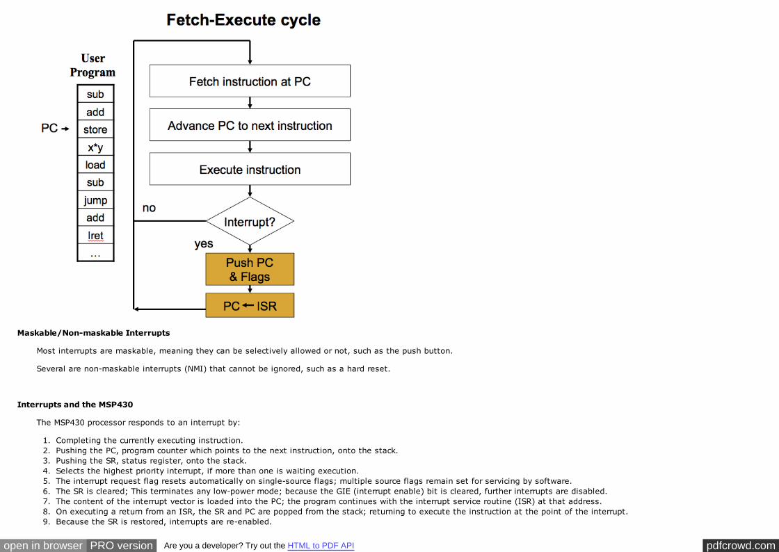
An interrupt normally results in:
1. Saving the program counter (PC), the address of the next instruction to fetch
2. Executing an interrupt procedure
3. On completing the interrupt procedure, the program counter is restored, so execution continues at the point of the interrupt.
pdfcrowd.comopen in browser PRO version Are you a developer? Try out the HTML to PDF API
Maskable/Non-maskable Interrupts
Most interrupts are maskable, meaning they can be selectively allowed or not, such as the push button.
Several are non-maskable interrupts (NMI) that cannot be ignored, such as a hard reset.
Interrupts and the MSP430
The MSP430 processor responds to an interrupt by:
1. Completing the currently executing instruction.2. Pushing the PC, program counter which points to the next instruction, onto the stack.3. Pushing the SR, status register, onto the stack.4. Selects the highest priority interrupt, if more than one is waiting execution.5. The interrupt request flag resets automatically on single-source flags; multiple source flags remain set for servicing by software.6. The SR is cleared; This terminates any low-power mode; because the GIE (interrupt enable) bit is cleared, further interrupts are disabled.7. The content of the interrupt vector is loaded into the PC; the program continues with the interrupt service routine (ISR) at that address.8. On executing a return from an ISR, the SR and PC are popped from the stack; returning to execute the instruction at the point of the interrupt.9. Because the SR is restored, interrupts are re-enabled.
pdfcrowd.comopen in browser PRO version Are you a developer? Try out the HTML to PDF API
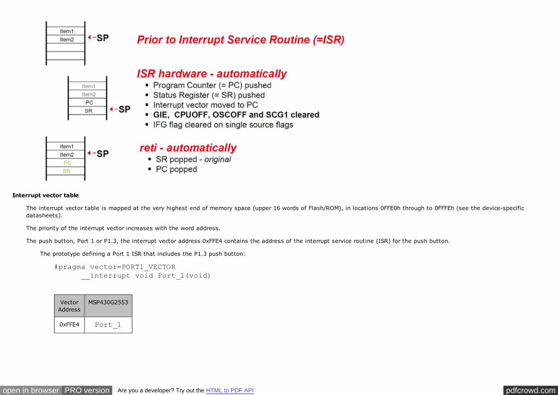
Interrupt vector table
The interrupt vector table is mapped at the very highest end of memory space (upper 16 words of Flash/ROM), in locations 0FFE0h through to 0FFFEh (see the device-specificdatasheets).
The priority of the interrupt vector increases with the word address.
The push button, Port 1 or P1.3, the interrupt vector address 0xFFE4 contains the address of the interrupt service routine (ISR) for the push button.
The prototype defining a Port 1 ISR that includes the P1.3 push button:
#pragma vector=PORT1_VECTOR __interrupt void Port_1(void)
VectorAddress
MSP430G2553
0xFFE4 Port_1

pdfcrowd.comopen in browser PRO version Are you a developer? Try out the HTML to PDF API
Programming the MSP430 for Push Button Interrupt
Each device must be initialized to generate an interrupt and the CPU must be enabled to respond to a maskable interrupt.
1. A mask setting determines which devices (e.g. push button) can generate an interrupt.
Interrupt mask, bit 3 (0x08) of P1.3 is the push button; 1 enables/0 disables. Must be 1 for the device to trigger an interrupt.
pdfcrowd.comopen in browser PRO version Are you a developer? Try out the HTML to PDF API
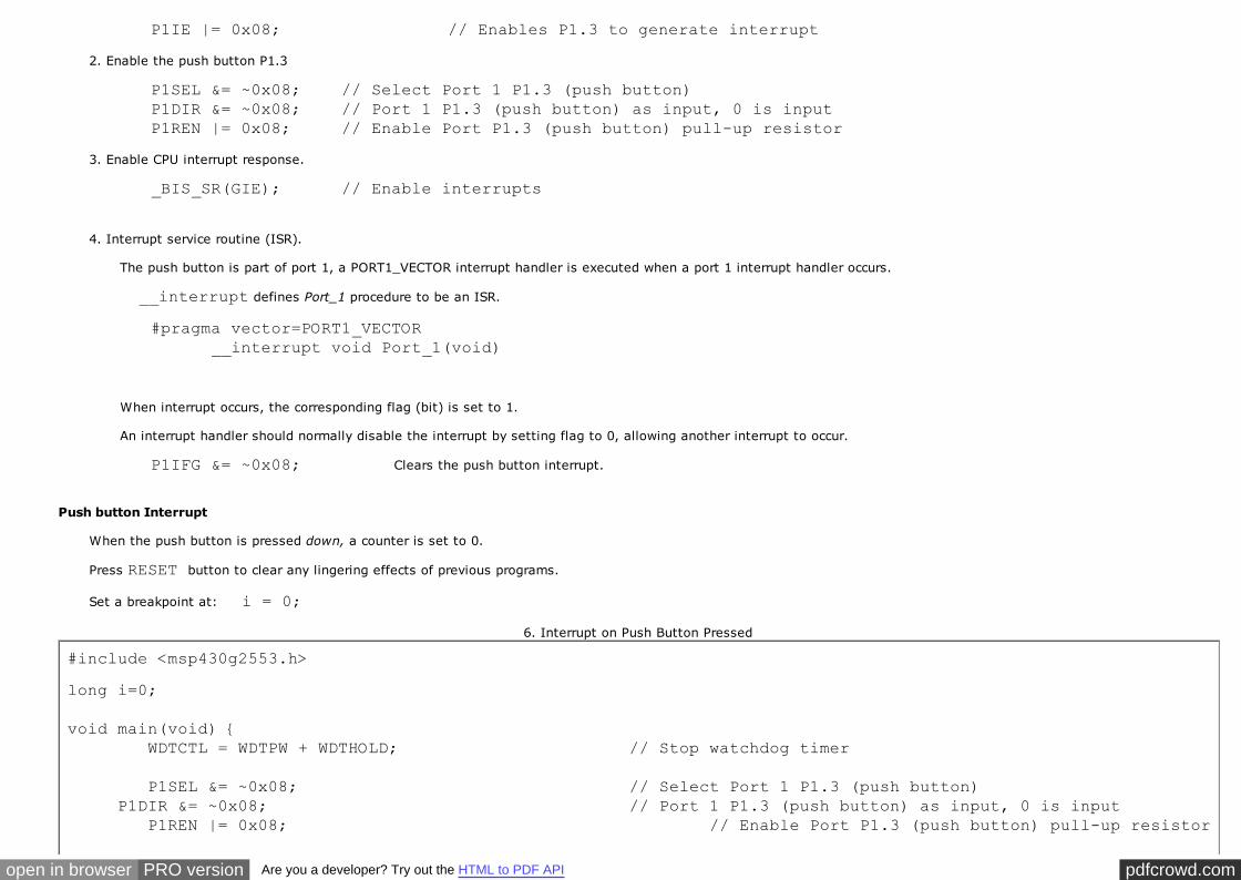
P1IE |= 0x08; // Enables P1.3 to generate interrupt
2. Enable the push button P1.3
P1SEL &= ~0x08; // Select Port 1 P1.3 (push button)P1DIR &= ~0x08; // Port 1 P1.3 (push button) as input, 0 is inputP1REN |= 0x08; // Enable Port P1.3 (push button) pull-up resistor
3. Enable CPU interrupt response.
_BIS_SR(GIE); // Enable interrupts
4. Interrupt service routine (ISR).
The push button is part of port 1, a PORT1_VECTOR interrupt handler is executed when a port 1 interrupt handler occurs.
__interrupt defines Port_1 procedure to be an ISR.
#pragma vector=PORT1_VECTOR __interrupt void Port_1(void)
When interrupt occurs, the corresponding flag (bit) is set to 1.
An interrupt handler should normally disable the interrupt by setting flag to 0, allowing another interrupt to occur.
P1IFG &= ~0x08; Clears the push button interrupt.
Push button Interrupt
When the push button is pressed down, a counter is set to 0.
Press RESET button to clear any lingering effects of previous programs.
Set a breakpoint at: i = 0;
6. Interrupt on Push Button Pressed
#include <msp430g2553.h>
long i=0;
void main(void) { WDTCTL = WDTPW + WDTHOLD; // Stop watchdog timer
P1SEL &= ~0x08; // Select Port 1 P1.3 (push button) P1DIR &= ~0x08; // Port 1 P1.3 (push button) as input, 0 is input P1REN |= 0x08; // Enable Port P1.3 (push button) pull-up resistor
pdfcrowd.comopen in browser PRO version Are you a developer? Try out the HTML to PDF API
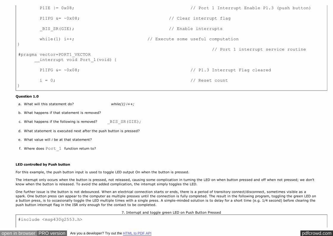
P1IE |= 0x08; // Port 1 Interrupt Enable P1.3 (push button)
P1IFG &= ~0x08; // Clear interrupt flag
_BIS_SR(GIE); // Enable interrupts
while(1) i++; // Execute some useful computation} // Port 1 interrupt service routine#pragma vector=PORT1_VECTOR __interrupt void Port_1(void) {
P1IFG &= ~0x08; // P1.3 Interrupt Flag cleared
i = 0; // Reset count}
Question 1.0
a. What will this statement do? while(1) i++;
b. What happens if that statement is removed?
c. What happens if the following is removed? _BIS_SR(GIE);
d. What statement is executed next after the push button is pressed?
e. What value will i be at that statement?
f. Where does Port_1 function return to?
LED controlled by Push button
For this example, the push button input is used to toggle LED output On when the button is pressed.
The interrupt only occurs when the button is pressed, not released, causing some complication in turning the LED on when button pressed and off when not pressed; we don'tknow when the button is released. To avoid the added complication, the interrupt simply toggles the LED.
One further issue is the button is not debounced. When an electrical connection starts or ends, there is a period of transitory connect/disconnect, sometimes visible as aspark. One button press can appear to the computer as multiple presses until the connection is fully completed. The result in the following program, toggling the green LED ona button press, is to occasionally toggle the LED multiple times with a single press. A simple-minded solution is to delay for a short time (e.g. 1/4 second) before clearing thepush button interrupt flag in the ISR only enough for the contact to be completed.
7. Interrupt and toggle green LED on Push Button Pressed
#include <msp430g2553.h>
pdfcrowd.comopen in browser PRO version Are you a developer? Try out the HTML to PDF API
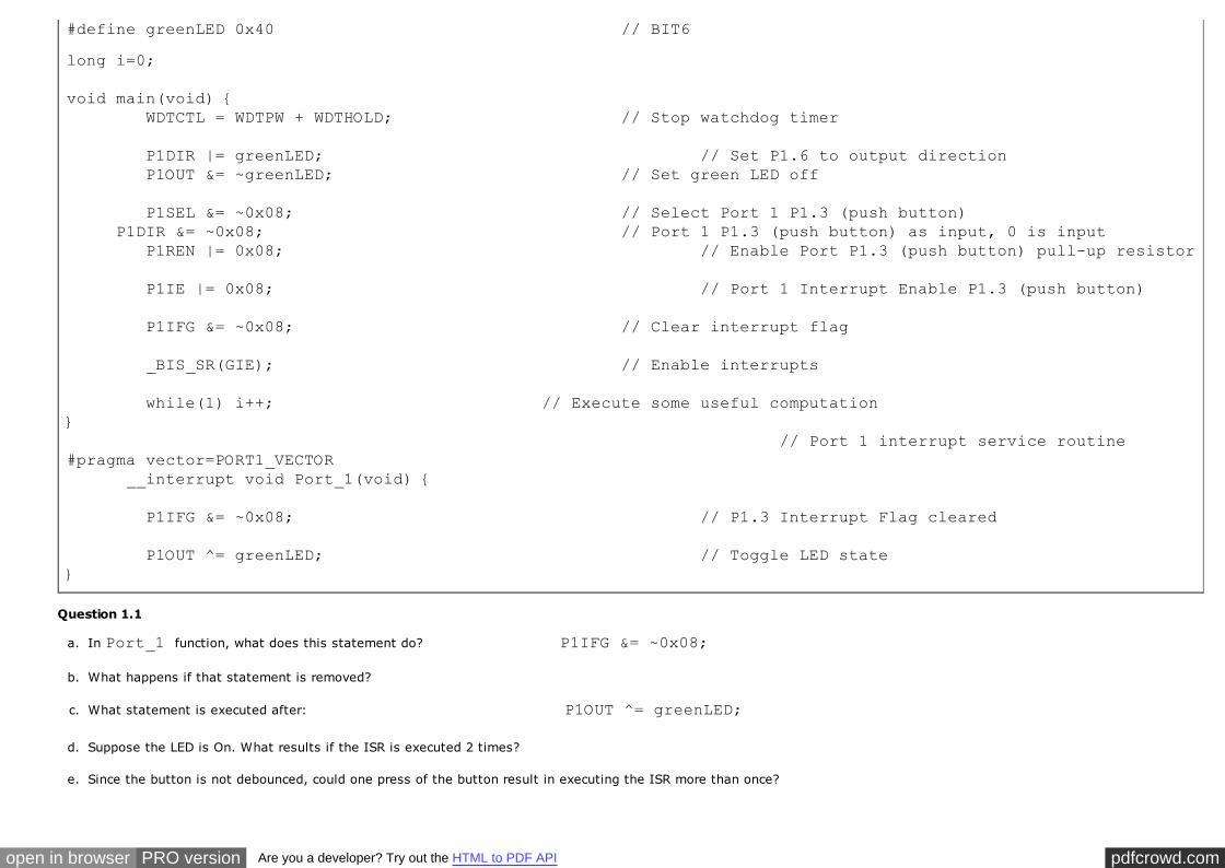
#define greenLED 0x40 // BIT6
long i=0;
void main(void) { WDTCTL = WDTPW + WDTHOLD; // Stop watchdog timer
P1DIR |= greenLED; // Set P1.6 to output direction P1OUT &= ~greenLED; // Set green LED off
P1SEL &= ~0x08; // Select Port 1 P1.3 (push button) P1DIR &= ~0x08; // Port 1 P1.3 (push button) as input, 0 is input P1REN |= 0x08; // Enable Port P1.3 (push button) pull-up resistor
P1IE |= 0x08; // Port 1 Interrupt Enable P1.3 (push button)
P1IFG &= ~0x08; // Clear interrupt flag
_BIS_SR(GIE); // Enable interrupts
while(1) i++; // Execute some useful computation} // Port 1 interrupt service routine#pragma vector=PORT1_VECTOR __interrupt void Port_1(void) {
P1IFG &= ~0x08; // P1.3 Interrupt Flag cleared
P1OUT ^= greenLED; // Toggle LED state}
Question 1.1
a. In Port_1 function, what does this statement do? P1IFG &= ~0x08;
b. What happens if that statement is removed?
c. What statement is executed after: P1OUT ^= greenLED;
d. Suppose the LED is On. What results if the ISR is executed 2 times?
e. Since the button is not debounced, could one press of the button result in executing the ISR more than once?
pdfcrowd.comopen in browser PRO version Are you a developer? Try out the HTML to PDF API
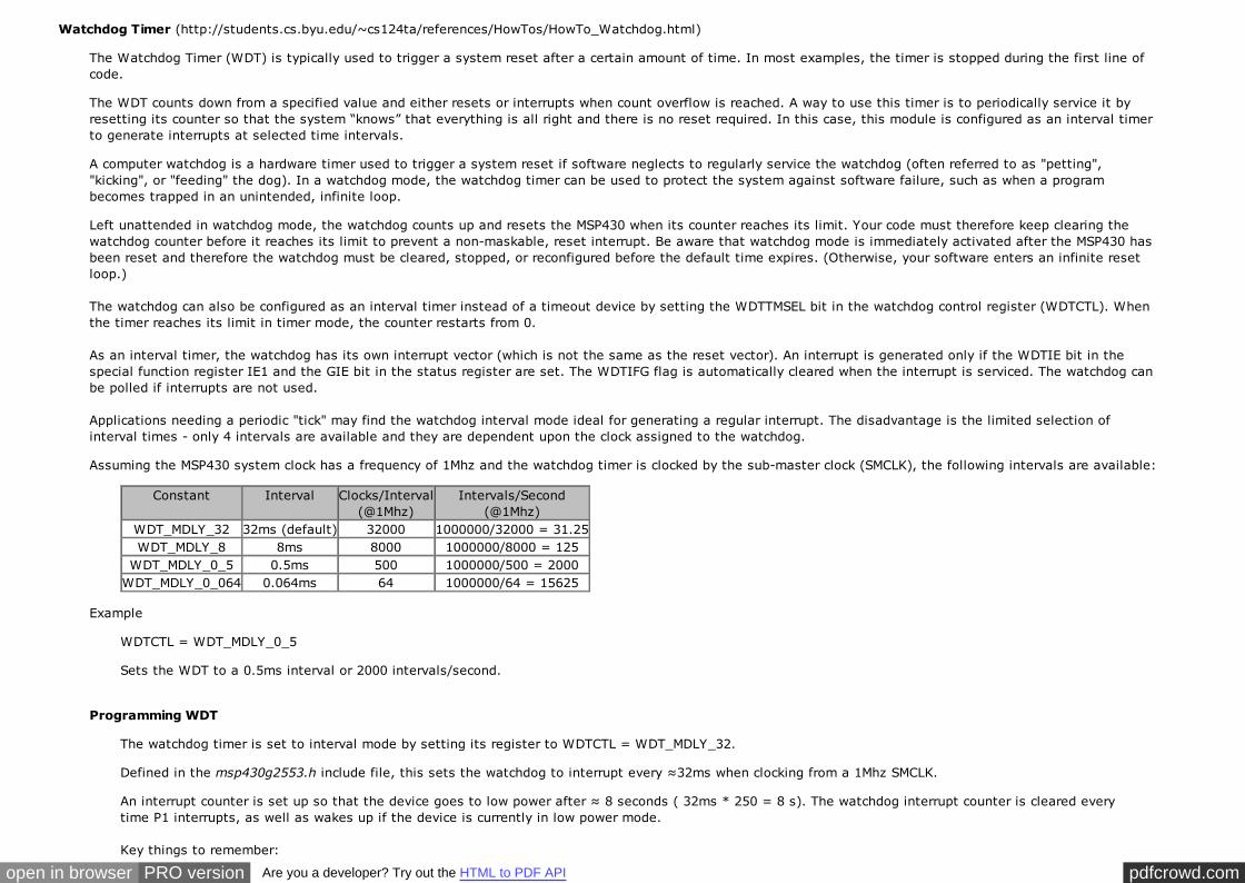
Watchdog Timer (http://students.cs.byu.edu/~cs124ta/references/HowTos/HowTo_Watchdog.html)
The Watchdog Timer (WDT) is typically used to trigger a system reset after a certain amount of time. In most examples, the timer is stopped during the first line ofcode.
The WDT counts down from a specified value and either resets or interrupts when count overflow is reached. A way to use this timer is to periodically service it byresetting its counter so that the system “knows” that everything is all right and there is no reset required. In this case, this module is configured as an interval timerto generate interrupts at selected time intervals.
A computer watchdog is a hardware timer used to trigger a system reset if software neglects to regularly service the watchdog (often referred to as "petting","kicking", or "feeding" the dog). In a watchdog mode, the watchdog timer can be used to protect the system against software failure, such as when a programbecomes trapped in an unintended, infinite loop.
Left unattended in watchdog mode, the watchdog counts up and resets the MSP430 when its counter reaches its limit. Your code must therefore keep clearing thewatchdog counter before it reaches its limit to prevent a non-maskable, reset interrupt. Be aware that watchdog mode is immediately activated after the MSP430 hasbeen reset and therefore the watchdog must be cleared, stopped, or reconfigured before the default time expires. (Otherwise, your software enters an infinite resetloop.)
The watchdog can also be configured as an interval timer instead of a timeout device by setting the WDTTMSEL bit in the watchdog control register (WDTCTL). Whenthe timer reaches its limit in timer mode, the counter restarts from 0.
As an interval timer, the watchdog has its own interrupt vector (which is not the same as the reset vector). An interrupt is generated only if the WDTIE bit in thespecial function register IE1 and the GIE bit in the status register are set. The WDTIFG flag is automatically cleared when the interrupt is serviced. The watchdog canbe polled if interrupts are not used.
Applications needing a periodic "tick" may find the watchdog interval mode ideal for generating a regular interrupt. The disadvantage is the limited selection ofinterval times - only 4 intervals are available and they are dependent upon the clock assigned to the watchdog.
Assuming the MSP430 system clock has a frequency of 1Mhz and the watchdog timer is clocked by the sub-master clock (SMCLK), the following intervals are available:
Constant Interval Clocks/Interval(@1Mhz)
Intervals/Second(@1Mhz)
WDT_MDLY_32 32ms (default) 32000 1000000/32000 = 31.25WDT_MDLY_8 8ms 8000 1000000/8000 = 125
WDT_MDLY_0_5 0.5ms 500 1000000/500 = 2000WDT_MDLY_0_064 0.064ms 64 1000000/64 = 15625
Example
WDTCTL = WDT_MDLY_0_5
Sets the WDT to a 0.5ms interval or 2000 intervals/second.
Programming WDT
The watchdog timer is set to interval mode by setting its register to WDTCTL = WDT_MDLY_32.
Defined in the msp430g2553.h include file, this sets the watchdog to interrupt every ≈32ms when clocking from a 1Mhz SMCLK.
An interrupt counter is set up so that the device goes to low power after ≈ 8 seconds ( 32ms * 250 = 8 s). The watchdog interrupt counter is cleared everytime P1 interrupts, as well as wakes up if the device is currently in low power mode.
Key things to remember:
pdfcrowd.comopen in browser PRO version Are you a developer? Try out the HTML to PDF API
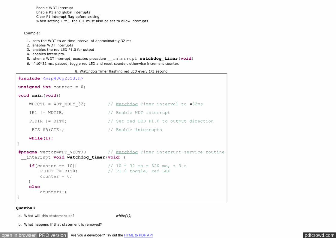
Enable WDT interrupt Enable P1 and global interrupts Clear P1 interrupt flag before exiting When setting LPM3, the GIE must also be set to allow interrupts
Example:
1. sets the WDT to an time interval of approximately 32 ms.2. enables WDT interrupts3. enables the red LED P1.0 for output4. enables interrupts.5. when a WDT interrupt, executes procedure __interrupt watchdog_timer(void)6. if 10*32 ms. passed, toggle red LED and reset counter, otherwise increment counter.
8. Watchdog Timer flashing red LED every 1/3 second
#include <msp430g2553.h>
unsigned int counter = 0;
void main(void){
WDTCTL = WDT_MDLY_32; // Watchdog Timer interval to ≈32ms
IE1 |= WDTIE; // Enable WDT interrupt
P1DIR |= BIT0; // Set red LED P1.0 to output direction
_BIS_SR(GIE); // Enable interrupts
while(1);}
#pragma vector=WDT_VECTOR // Watchdog Timer interrupt service routine __interrupt void watchdog_timer(void) {
if(counter == 10){ // 10 * 32 ms = 320 ms, ≈.3 s P1OUT ^= BIT0; // P1.0 toggle, red LED counter = 0; } else counter++;}
Question 2
a. What will this statement do? while(1);
b. What happens if that statement is removed?

pdfcrowd.comopen in browser PRO version Are you a developer? Try out the HTML to PDF API
c. What happens if the following is removed? _BIS_SR(GIE);
d. What changes are needed to toggle every second?
Constant Interval Clocks/Interval(@1Mhz)
Intervals/Second(@1Mhz)
WDT_MDLY_32 32ms (default) 32000 1000000/32000 = 31.25WDT_MDLY_8 8ms 8000 1000000/8000 = 125
WDT_MDLY_0_5 0.5ms 500 1000000/500 = 2000WDT_MDLY_0_064 0.064ms 64 1000000/64 = 15625
Watchdog Timer/Low Power Mode
Low power mode is a feature for which the MSP430 is designed. Useful because it shuts down certain areas of the CPU in order to save power.
Since most embedded systems need to be energy efficient, low power modes of operation are employed. The MSP430 features five modes of operation, yet the mostpopular 3 are the following (the others can be found in the datasheet):
1. Active mode (AM), I ≈ 300 uA a. All clocks are active
2. Low-power mode 0 (LPM0), I ≈ 85uA a. CPU is disabled b. ACLK and SMCLK remain active, MCLK is disabled
3. Low-power mode 3 (LPM3), I ≈ 1uA a. CPU is disabled b. MCLK and SMCLK disabled c. ACLK remains active d. DCO’s dc-generator is disabled
Interrupts can wake up the device from any low power mode, process, and decide whether to restore the low power or active mode.
Note that modes 0 and 3 disable the CPU, preventing the execution of any program instructions. Also that the master clock, MCLK, driving the CPU is disabled.
However, interrupts from the push button or timers can still occur if interrupts are enabled.
WDT is normally clocked by SubMain or subsystem clock (SMCLK).
In mode 0 the WDT remains operating but in mode 3 it is effectively disabled.
Example
Operates in low power mode to put the CPU to sleep.
9. Low Power Mode
#include <msp430g2553.h>
volatile unsigned int i=0;
pdfcrowd.comopen in browser PRO version Are you a developer? Try out the HTML to PDF API
void main(void) {
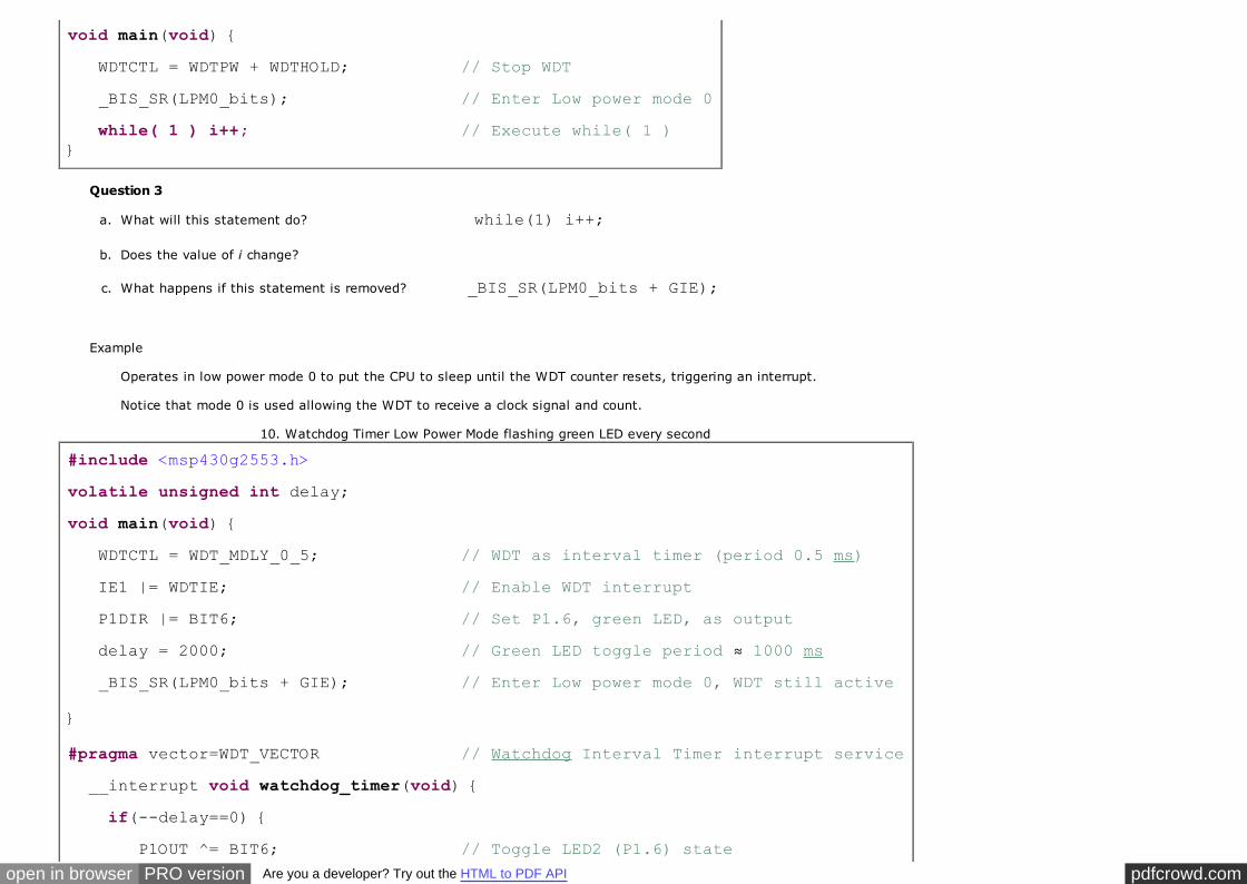
WDTCTL = WDTPW + WDTHOLD; // Stop WDT
_BIS_SR(LPM0_bits); // Enter Low power mode 0
while( 1 ) i++; // Execute while( 1 )}
Question 3
a. What will this statement do? while(1) i++;
b. Does the value of i change?
c. What happens if this statement is removed? _BIS_SR(LPM0_bits + GIE);
Example
Operates in low power mode 0 to put the CPU to sleep until the WDT counter resets, triggering an interrupt.
Notice that mode 0 is used allowing the WDT to receive a clock signal and count.
10. Watchdog Timer Low Power Mode flashing green LED every second
#include <msp430g2553.h>
volatile unsigned int delay;
void main(void) {
WDTCTL = WDT_MDLY_0_5; // WDT as interval timer (period 0.5 ms)
IE1 |= WDTIE; // Enable WDT interrupt
P1DIR |= BIT6; // Set P1.6, green LED, as output
delay = 2000; // Green LED toggle period ≈ 1000 ms
_BIS_SR(LPM0_bits + GIE); // Enter Low power mode 0, WDT still active
}
#pragma vector=WDT_VECTOR // Watchdog Interval Timer interrupt service
__interrupt void watchdog_timer(void) {
if(--delay==0) {
P1OUT ^= BIT6; // Toggle LED2 (P1.6) state
pdfcrowd.comopen in browser PRO version Are you a developer? Try out the HTML to PDF API
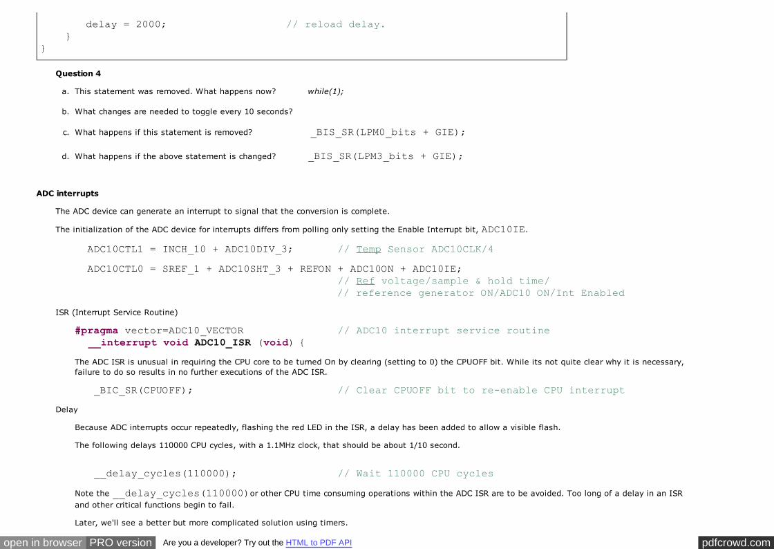
delay = 2000; // reload delay. }}
Question 4
a. This statement was removed. What happens now? while(1);
b. What changes are needed to toggle every 10 seconds?
c. What happens if this statement is removed? _BIS_SR(LPM0_bits + GIE);
d. What happens if the above statement is changed? _BIS_SR(LPM3_bits + GIE);
ADC interrupts
The ADC device can generate an interrupt to signal that the conversion is complete.
The initialization of the ADC device for interrupts differs from polling only setting the Enable Interrupt bit, ADC10IE.
ADC10CTL1 = INCH_10 + ADC10DIV_3; // Temp Sensor ADC10CLK/4
ADC10CTL0 = SREF_1 + ADC10SHT_3 + REFON + ADC10ON + ADC10IE; // Ref voltage/sample & hold time/ // reference generator ON/ADC10 ON/Int Enabled
ISR (Interrupt Service Routine)
#pragma vector=ADC10_VECTOR // ADC10 interrupt service routine __interrupt void ADC10_ISR (void) {
The ADC ISR is unusual in requiring the CPU core to be turned On by clearing (setting to 0) the CPUOFF bit. While its not quite clear why it is necessary,failure to do so results in no further executions of the ADC ISR.
_BIC_SR(CPUOFF); // Clear CPUOFF bit to re-enable CPU interrupt
Delay
Because ADC interrupts occur repeatedly, flashing the red LED in the ISR, a delay has been added to allow a visible flash.
The following delays 110000 CPU cycles, with a 1.1MHz clock, that should be about 1/10 second.
__delay_cycles(110000); // Wait 110000 CPU cycles
Note the __delay_cycles(110000)or other CPU time consuming operations within the ADC ISR are to be avoided. Too long of a delay in an ISRand other critical functions begin to fail.
Later, we'll see a better but more complicated solution using timers.
pdfcrowd.comopen in browser PRO version Are you a developer? Try out the HTML to PDF API
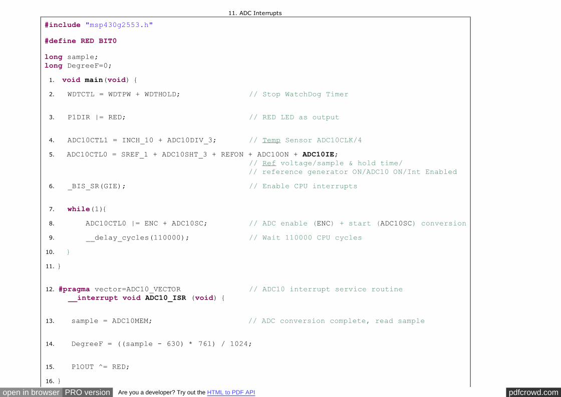
11. ADC Interrupts
#include "msp430g2553.h"
#define RED BIT0
long sample;long DegreeF=0;
1. void main(void) {
2. WDTCTL = WDTPW + WDTHOLD; // Stop WatchDog Timer
3. P1DIR |= RED; // RED LED as output
4. ADC10CTL1 = INCH_10 + ADC10DIV_3; // Temp Sensor ADC10CLK/4
5. ADC10CTL0 = SREF_1 + ADC10SHT_3 + REFON + ADC10ON + ADC10IE; // Ref voltage/sample & hold time/ // reference generator ON/ADC10 ON/Int Enabled
6. _BIS_SR(GIE); // Enable CPU interrupts
7. while(1){
8. ADC10CTL0 |= ENC + ADC10SC; // ADC enable (ENC) + start (ADC10SC) conversion
9. __delay_cycles(110000); // Wait 110000 CPU cycles
10. }
11. }
12. #pragma vector=ADC10_VECTOR // ADC10 interrupt service routine __interrupt void ADC10_ISR (void) {
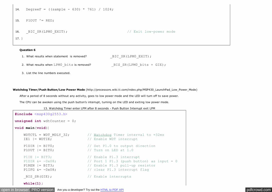
13. sample = ADC10MEM; // ADC conversion complete, read sample
14. DegreeF = ((sample - 630) * 761) / 1024;
15. P1OUT ^= RED;
16. }
pdfcrowd.comopen in browser PRO version Are you a developer? Try out the HTML to PDF API
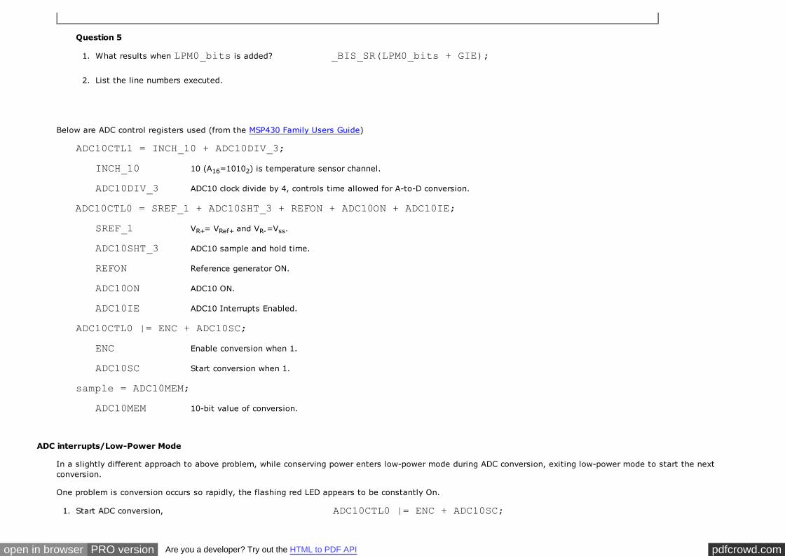
Question 5
1. What results when LPM0_bits is added? _BIS_SR(LPM0_bits + GIE);
2. List the line numbers executed.
Below are ADC control registers used (from the MSP430 Family Users Guide)
ADC10CTL1 = INCH_10 + ADC10DIV_3;
INCH_10 10 (A16=10102) is temperature sensor channel.
ADC10DIV_3 ADC10 clock divide by 4, controls time allowed for A-to-D conversion.
ADC10CTL0 = SREF_1 + ADC10SHT_3 + REFON + ADC10ON + ADC10IE;
SREF_1 VR+= VRef+ and VR-=Vss.
ADC10SHT_3 ADC10 sample and hold time.
REFON Reference generator ON.
ADC10ON ADC10 ON.
ADC10IE ADC10 Interrupts Enabled.
ADC10CTL0 |= ENC + ADC10SC;
ENC Enable conversion when 1.
ADC10SC Start conversion when 1.
sample = ADC10MEM;
ADC10MEM 10-bit value of conversion.
ADC interrupts/Low-Power Mode
In a slightly different approach to above problem, while conserving power enters low-power mode during ADC conversion, exiting low-power mode to start the nextconversion.
One problem is conversion occurs so rapidly, the flashing red LED appears to be constantly On.
1. Start ADC conversion, ADC10CTL0 |= ENC + ADC10SC;
pdfcrowd.comopen in browser PRO version Are you a developer? Try out the HTML to PDF API
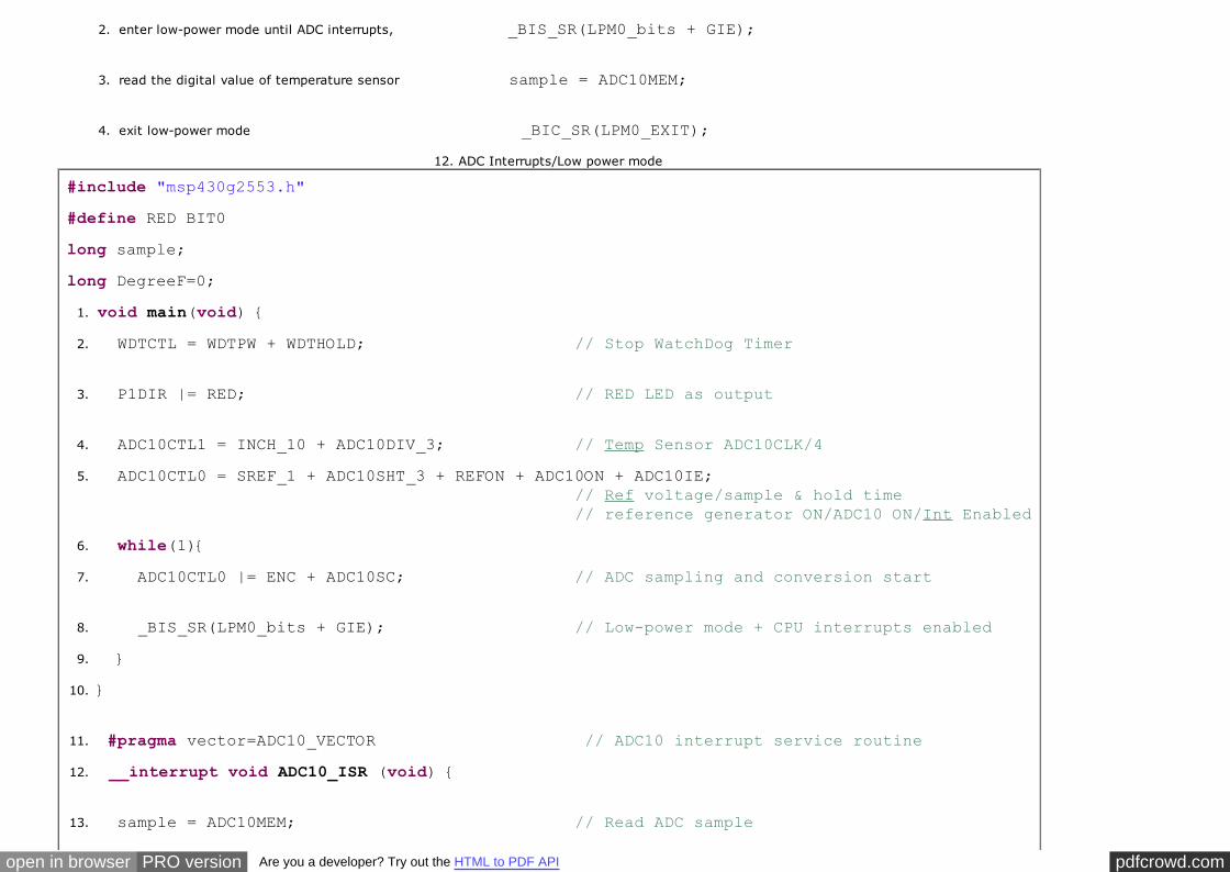
2. enter low-power mode until ADC interrupts, _BIS_SR(LPM0_bits + GIE);
3. read the digital value of temperature sensor sample = ADC10MEM;
4. exit low-power mode _BIC_SR(LPM0_EXIT);
12. ADC Interrupts/Low power mode
#include "msp430g2553.h"
#define RED BIT0
long sample;
long DegreeF=0;
1. void main(void) {
2. WDTCTL = WDTPW + WDTHOLD; // Stop WatchDog Timer
3. P1DIR |= RED; // RED LED as output
4. ADC10CTL1 = INCH_10 + ADC10DIV_3; // Temp Sensor ADC10CLK/4
5. ADC10CTL0 = SREF_1 + ADC10SHT_3 + REFON + ADC10ON + ADC10IE; // Ref voltage/sample & hold time // reference generator ON/ADC10 ON/Int Enabled
6. while(1){
7. ADC10CTL0 |= ENC + ADC10SC; // ADC sampling and conversion start
8. _BIS_SR(LPM0_bits + GIE); // Low-power mode + CPU interrupts enabled
9. }
10. }
11. #pragma vector=ADC10_VECTOR // ADC10 interrupt service routine
12. __interrupt void ADC10_ISR (void) {
13. sample = ADC10MEM; // Read ADC sample
pdfcrowd.comopen in browser PRO version Are you a developer? Try out the HTML to PDF API
14. DegreeF = ((sample - 630) * 761) / 1024;
15. P1OUT ^= RED;
16. _BIC_SR(LPM0_EXIT); // Exit low-power mode
17. }
Question 6
1. What results when statement is removed? _BIC_SR(LPM0_EXIT);
2. What results when LPM0_bits is removed? _BIS_SR(LPM0_bits + GIE);
3. List the line numbers executed.
Watchdog Timer/Push Button/Low Power Mode (http://processors.wiki.ti.com/index.php/MSP430_LaunchPad_Low_Power_Mode)
After a period of 8 seconds without any activity, goes to low power mode and the LED will turn off to save power.
The CPU can be awoken using the push button’s interrupt, turning on the LED and exiting low power mode.
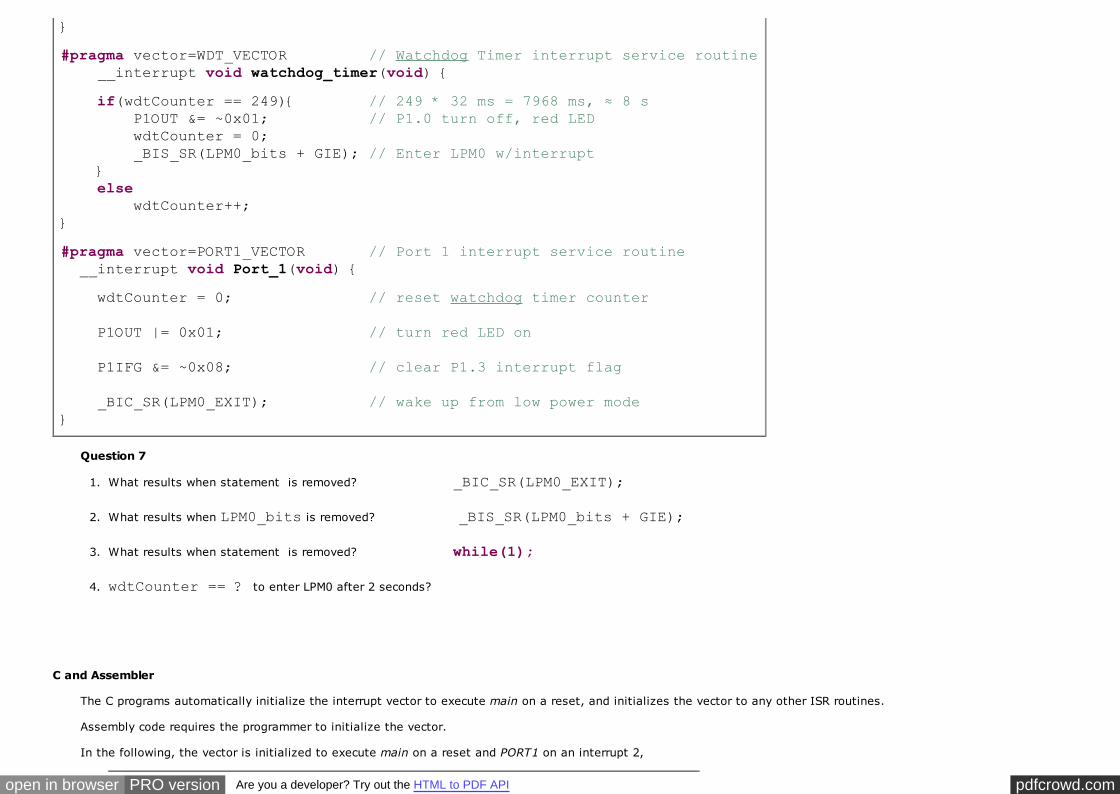
13. Watchdog Timer enter LPM after 8 seconds - Push Button Interrupt exit LPM
#include <msp430g2553.h>
unsigned int wdtCounter = 0;
void main(void){
WDTCTL = WDT_MDLY_32; // Watchdog Timer interval to ≈32ms IE1 |= WDTIE; // Enable WDT interrupt
P1DIR |= BIT0; // Set P1.0 to output direction P1OUT |= BIT0; // Turn on LED at 1.0
P1IE |= BIT3; // Enable P1.3 interrupt P1DIR &= ~0x08; // Port 1 P1.3 (push button) as input = 0 P1REN |= BIT3; // Enable P1.3 pull-up resistor P1IFG &= ~0x08; // clear P1.3 interrupt flag
_BIS_SR(GIE); // Enable interrupts
while(1);
pdfcrowd.comopen in browser PRO version Are you a developer? Try out the HTML to PDF API
}
#pragma vector=WDT_VECTOR // Watchdog Timer interrupt service routine __interrupt void watchdog_timer(void) {
if(wdtCounter == 249){ // 249 * 32 ms = 7968 ms, ≈ 8 s P1OUT &= ~0x01; // P1.0 turn off, red LED wdtCounter = 0; _BIS_SR(LPM0_bits + GIE); // Enter LPM0 w/interrupt } else wdtCounter++;}
#pragma vector=PORT1_VECTOR // Port 1 interrupt service routine __interrupt void Port_1(void) {
wdtCounter = 0; // reset watchdog timer counter
P1OUT |= 0x01; // turn red LED on
P1IFG &= ~0x08; // clear P1.3 interrupt flag
_BIC_SR(LPM0_EXIT); // wake up from low power mode}
Question 7
1. What results when statement is removed? _BIC_SR(LPM0_EXIT);
2. What results when LPM0_bits is removed? _BIS_SR(LPM0_bits + GIE);
3. What results when statement is removed? while(1);
4. wdtCounter == ? to enter LPM0 after 2 seconds?
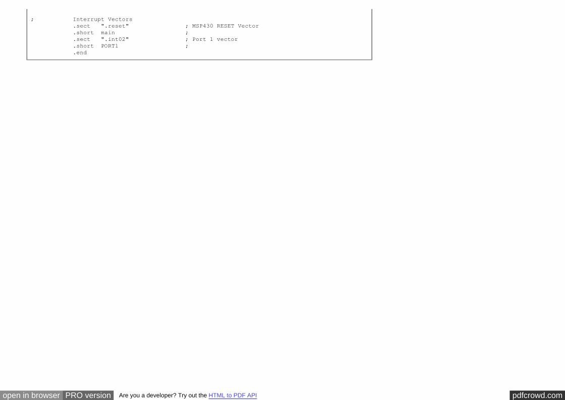
C and Assembler
The C programs automatically initialize the interrupt vector to execute main on a reset, and initializes the vector to any other ISR routines.
Assembly code requires the programmer to initialize the vector.
In the following, the vector is initialized to execute main on a reset and PORT1 on an interrupt 2,

pdfcrowd.comopen in browser PRO version Are you a developer? Try out the HTML to PDF API
; Interrupt Vectors .sect ".reset" ; MSP430 RESET Vector .short main ; .sect ".int02" ; Port 1 vector .short PORT1 ; .end
Interrupt on Push Button Pressed
#include <msp430g2553.h>
#define LED_1 0x40 // BIT6
void main(void) { WDTCTL = WDTPW + WDTHOLD; // Stop watchdog timer
P1DIR |= LED_1; // Set P1.6 to output direction P1OUT &= ~LED_1; // Set the LED off P1SEL &= ~0x08; // Select Port 1 P1.3 (push button) P1IE |= 0x08; // Port 1 Interrupt Enable P1.3 (push button)
__enable_interrupt(); // Enable interrupts
while(1); // Execute }
// Port 1 interrupt service routine#pragma vector=PORT1_VECTOR __interrupt void Port_1(void) { P1IFG &= ~0x08; // P1.3 Interrupt Flag cleared P1OUT ^= LED_1; // Toggle LED state}
.cdecls C,LIST, "msp430G2553.h" .text ; Assemble to Flash memory
main mov.w #0280h,SP ; Set stackpointer (128B RAM device) mov.w #WDTPW+WDTHOLD,&WDTCTL ; Stop watchdog timer bis.b #01000000b,&P1DIR ; P1DIR.6 = 1, output direction bic.b #00001000b,&P1DIR ; P1DIR.3 = 0, input direction bic.b #00001000b,&P1SEL ; Select Port 1 (push button) bic.b #01000000b,&P1OUT ; P1OUT.6 = 0, LED off bis.b #00001000b,&P1IE ; P1IE.3 = 1, enable interrupt on Port 1, push button eint ; Enable processor interrupts _while jmp _while ; while(1);_endwhile
PORT1 bic.b #00001000b, &P1IFG ; P1IFG.3 = 0, clear push button interrupt xor.b #01000000b, &P1OUT ; P1OUT.6 toggle LED reti
pdfcrowd.comopen in browser PRO version Are you a developer? Try out the HTML to PDF API
; Interrupt Vectors .sect ".reset" ; MSP430 RESET Vector .short main ; .sect ".int02" ; Port 1 vector .short PORT1 ; .end