important - usa.yamaha.com · características del panel inferior de la unidad del teclado...
TRANSCRIPT
IMPORTANTCheck your power supplyMake sure that your local AC mains voltage matches thevoltage specified on the name plate on the bottom panel. Insome areas a voltage selector may be provided on the bottompanel of the main keyboard unit near the power cord. Makesure that the voltage selector is set for the voltage in your area.The voltage selector is set at 240V when the unit is initiallyshipped. To change the setting use a “minus” screwdriver torotate the selector dial so that the correct voltage appears nextto the pointer on the panel.
WICHTIGÜberprüfung der StromversorgungVergewissern Sie sich vor dem Anschließen an das Stromnetz,daß die örtliche Netzspannung den Betriebsspannungswertenauf dem Typenschild an der Unterseite des Instrumentsentspricht. In bestimmten Verkaufsgebieten ist das Instrumentmit einem Spannungswähler an der Unterseite neben derNetzkabeldurchführung ausgestattet. Falls vorhanden, muß derSpannungswähler auf die örtliche Netzspannung eingestelltwerden. Der Spannungswähler wurde werkseitig auf 240 Vvoreingestellt. Zum Verstellen drehen Sie den Spannungsreglermit einem Schlitzschraubendreher, bis der Zeiger auf denkorrekten Spannungswert weist
IMPORTANTContrôler la source d’alimentationVérifiez que la tension spécifiée sur le panneau arrièrecorrespond à la tension du secteur. Dans certaines régions,l’instrument peut être équipé d’un sélecteur de tension situé surle panneau inférieur du clavier à proximité du cordon d’alimen-tation. Vérifiez que ce sélecteur est bien réglé en fonction dela tension secteur de votre région. Le sélecteur de tension estréglé sur 240 V au départ d’usine. Pour modifier ce réglage,utilisez un tournevis à lame plate pour tourner le sélecteur afinde mettre l’indication correspondant à la tension de votrerégion vis à vis du repère triangulaire situé sur le panneau.
IMPORTANTEVerifique la alimentación de corrienteAsegúrese de que tensión de alimentación de CA de su áreacorresponde con la tensión especificada en la placa decaracterísticas del panel inferior de la unidad del tecladoprincipal, cerca del cable de alimentación. Asegúrese de queel selector de tensión esté ajustado a la tensión de su área. Elselector de tensión se ajusta a 240V cuando la unidad sale defábrica. Para cambiar el ajuste, emplee un destornillador decabeza “recta” para girar el selector de modo que aparezca latensión correcta al lado del indicador del panel.

92-469 1
ENVIRONMENTAL ISSUES: Yamaha strives to pro-duce products that are both user safe and environmentallyfriendly. We sincerely believe that our products and theproduction methods used to produce them, meet thesegoals. In keeping with both the letter and the spirit of thelaw, we want you to be aware of the following:
Battery Notice: This product MAY contain a small non-rechargable battery which (if applicable) is soldered inplace. The average life span of this type of battery is ap-proximately five years. When replacement becomes nec-essary, contact a qualified service representative to per-form the replacement.
Warning: Do not attempt to recharge, disassemble, orincinerate this type of battery. Keep all batteries awayfrom children. Dispose of used batteries promptly and asregulated by applicable laws. Note: In some areas, theservicer is required by law to return the defective parts.However, you do have the option of having the servicerdispose of these parts for you.
Disposal Notice: Should this product become damagedbeyond repair, or for some reason its useful life is consid-ered to be at an end, please observe all local, state, andfederal regulations that relate to the disposal of productsthat contain lead, batteries, plastics, etc.
NOTICE: Service charges incurred due to lack of knowl-edge relating to how a function or effect works (when theunit is operating as designed) are not covered by themanufacturer’s warranty, and are therefore the ownersresponsibility. Please study this manual carefully and con-sult your dealer before requesting service.
NAME PLATE LOCATION: The graphic below indi-cates the location of the name plate. The model number,serial number, power requirements, etc., are located onthis plate. You should record the model number, serialnumber, and the date of purchase in the spaces providedbelow and retain this manual as a permanent record ofyour purchase.
CAUTIONRISK OF ELECTRIC SHOCK
DO NOT OPEN
CAUTION: TO REDUCE THE RISK OF ELECTRIC SHOCK.DO NOT REMOVE COVER (OR BACK).
NO USER-SERVICEABLE PARTS INSIDE.REFER SERVICING TO QUALIFIED SERVICE PERSONNEL.
PRODUCT SAFETY MARKINGS: Yamaha electronicproducts may have either labels similar to the graphicsshown below or molded/stamped facsimiles of thesegraphics on the enclosure. The explanation of these graph-ics appears on this page. Please observe all cautions indi-cated on this page and those indicated in the safety in-struction section.
See bottom of Keyboard enclosure for graphic symbol markings
The exclamation point within the equi-lateral triangle is intended to alert theuser to the presence of important oper-ating and maintenance (servicing) in-structions in the literature accompany-ing the product.
The lightning flash with arrowheadsymbol, within the equilateral triangle,is intended to alert the user to the pres-ence of uninsulated “dangerous volt-age” within the product’s enclosure thatmay be of sufficient magnitude to con-stitute a risk of electrical shock.
IMPORTANT NOTICE: All Yamaha electronic prod-ucts are tested and approved by an independent safetytesting laboratory in order that you may be sure that whenit is properly installed and used in its normal and custom-ary manner, all foreseeable risks have been eliminated.DO NOT modify this unit or commission others to do sounless specifically authorized by Yamaha. Product per-formance and/or safety standards may be diminished.Claims filed under the expressed warranty may be deniedif the unit is/has been modified. Implied warranties mayalso be affected.
SPECIFICATIONS SUBJECT TO CHANGE: Theinformation contained in this manual is believed to becorrect at the time of printing. However, Yamaha reservesthe right to change or modify any of the specificationswithout notice or obligation to update existing units.
SPECIAL MESSAGE SECTION
Model _____________________________________
Serial No. __________________________________
Purchase Date ______________________________
WARNING- When using any electrical or electronic prod-uct, basic precautions should always be followed. These pre-cautions include, but are not limited to, the following:
1. Read all Safety Instructions, Installation Instructions,Special Message Section items, and any Assembly Instructionsfound in this manual BEFORE marking any connections, in-cluding connection to the main supply.
2. Main Power Supply Verification: Yamaha products aremanufactured specifically for the supply voltage in the areawhere they are to be sold. If you should move, or if any doubtexists about the supply voltage in your area, please contactyour dealer for supply voltage verification and (if applicable)instructions. The required supply voltage is printed on thename plate. For name plate location, please refer to the graphicfound in the Special Message Section of this manual.
3. This product may be equipped with a polarized plug(one blade wider than the other). If you are unable to insert theplug into the outlet, turn the plug over and try again. If theproblem persists, contact an electrician to have the obsoleteoutlet replaced. Do NOT defeat the safety purpose of the plug.
4. Some electronic products utilize external power sup-plies or adapters. Do NOT connect this type of product to anypower supply or adapter other than one described in the ownersmanual, on the name plate, or specifically recommended byYamaha.
5. WARNING: Do not place this product or any otherobjects on the power cord or place it in a position where any-one could walk on, trip over, or roll anything over power orconnecting cords of any kind. The use of an extension cord isnot recommended! If you must use an extension cord, theminimum wire size for a 25' cord (or less) is 18 AWG. NOTE:The smaller the AWG number, the larger the current handlingcapacity. For longer extension cords, consult a local electri-cian.
6. Ventilation: Electronic products, unless specificallydesigned for enclosed installations, should be placed in loca-tions that do not interfere with proper ventilation. If instruc-tions for enclosed installations are not provided, it must beassumed that unobstructed ventilation is required.
7. Temperature considerations: Electronic productsshould be installed in locations that do not significantly con-tribute to their operating temperature. Placement of this prod-uct close to heat sources such as; radiators, heat registers andother devices that produce heat should be avoided.
8. This product was NOT designed for use in wet/damp loca-tions and should not be used near water or exposed to rain. Exam-ples of wet/damp locations are; near a swimming pool, spa, tub,sink, or wet basement.
9. This product should be used only with the componentssupplied or; a cart, rack, or stand that is recommended by themanufacturer. If a cart, rack, or stand is used, please observe allsafety markings and instructions that accompany the accessoryproduct.
10. The power supply cord (plug) should be disconnected fromthe outlet when electronic products are to be left unused for ex-tended periods of time. Cords should also be disconnected whenthere is a high probability of lightening and/or electrical stormactivity.
11. Care should be taken that objects do not fall and liquids arenot spilled into the enclosure through any openings that may exist.
12. Electrical/electronic products should be serviced by aqualified service person when:
a. The power supply cord has been damaged; orb. Objects have fallen, been inserted, or liquids have been
spilled into the enclosure through openings; orc. The product has been exposed to rain: ord. The product dose not operate, exhibits a marked change
in performance; ore. The product has been dropped, or the enclosure of the
product has been damaged.
13. Do not attempt to service this product beyond that de-scribed in the user-maintenance instructions. All other servicingshould be referred to qualified service personnel.
14. This product, either alone or in combination with an ampli-fier and headphones or speaker/s, may be capable of producingsound levels that could cause permanent hearing loss. DO NOToperate for a long period of time at a high volume level or at alevel that is uncomfortable. If you experience any hearing loss orringing in the ears, you should consult an audiologist.IMPORTANT: The louder the sound, the shorter the time periodbefore damage occurs.
15. Some Yamaha products may have benches and/or acces-sory mounting fixtures that are either supplied as a part of theproduct or as optional accessories. Some of these items are de-signed to be dealer assembled or installed Please make sure thatbenches are stable and any optional fixtures (where applicable) arewell secured BEFORE using. Benches supplied by Yamaha aredesigned for seating only. No other uses are recommended.
INFORMATION RELATING TO PERSONAL INJURY, ELECTRICAL SHOCK,AND FIRE HAZARD POSSIBILITIES HAS BEEN INCLUDED IN THIS LIST.
IMPORTANT SAFETY INSTRUCTIONS
PLEASE KEEP THIS MANUAL92-469-2
vii

Introduction
Thank you for choosing a Yamaha CLP-311 Clavinova. Your Clavinova is a fine musical instrument thatemploys advanced Yamaha music technology. With the proper care, your Clavinova will give you manyyears of musical pleasure.
Yamaha’s AWM (Advanced Wave Memory) tonegenerator system offers rich, realistic voices.
Piano-like touch response provides extensiveexpressive control and outstanding playability.
Dual play mode allows 2 voices to be playedsimultaneously.
Unique Clavinova Tone voice provides a freshsound for new musical expression.
Metronome feature with variable tempo facilitatespractice.
Record and play back anything you play on thekeyboard (up to approximately 1,300 notes).
MIDI compatibility and a range of MIDI functionsmake the Clavinova useful in a range of advancedMIDI music systems.
Taking Care Of Your Clavinova
Your Clavinova is a fine musical instrument, and deserves the most careful treatment. Observe the fol-lowing points and your Clavinova will sound and look great for many years.
1 Never open the case and touch or tamper with theinternal circuitry.
2 Always turn the POWER switch OFF after use,and cover the keyboard with the dust coverprovided.
3 Clean the cabinet and keys of your Clavinova onlywith a clean, slightly damp cloth. A neutralcleanser may be used if desired. Never useabrasive cleansers, waxes, solvents or chemicaldust cloths since these can dull or damage thefinish.
4 Never place any vinyl products on your Clavinova.Contact with vinyl can cause irreversible damageto the finish.
5 Install your Clavinova in a place that is away fromdirect sunlight, excessive humidity or heat.
6 Never apply excessive force to the controls,connectors or other parts of your Clavinova, andavoid scratching or bumping it with hard objects.
7 Make sure that your local AC mains voltagematches the voltage specified on the name plateon the bottom panel. In some areas a voltageselector may be provided on the bottom panel ofthe main keyboard unit near the power cord.Make sure that the voltage selector is set for thevoltage in your area. The voltage selector is set at240V when the unit is initially shipped. To changethe setting use a “minus” screwdriver to rotate theselector dial so that the correct voltage appearsnext to the pointer on the panel.
Name Plate LocationThe CLP-311 name plate is located on thebottom panel.
In order to make the most of your Clavinova’s performance potential and features, we urge you to readthis Owner’s Manual thoroughly, and keep it in a safe place for later reference.

C L P - 3 1 1
EnglishOwner’s Manual
DeutschBedienungsanleitung
FrançaisMode d’emploi
EspañolManual de instrucciones

Contents
The Control Panel ............................................................................................ 2Connections .....................................................................................................4
Selecting & Playing Voices .............................................................................5
Playing the Demonstration Tunes ..................................................................6
The Dual Mode ................................................................................................7 Adjusting the Balance Between the Dual-mode Voices .................. 7 Shifting a Dual-Mode Voice Up One Octave ................................... 7
The Pedals .......................................................................................................8 Soft/Sostenuto (Left) Pedal ............................................................. 8 Damper (Right) Pedal ..................................................................... 8
Transposition ................................................................................................... 8
Pitch Control .................................................................................................... 9 Tuning Up ........................................................................................ 9 Tuning Down ...................................................................................9 To Restore Standard Pitch .............................................................. 9
The Metronome & Tempo Control ................................................................10 The Metronome ..................................................................................10
Metronome Volume .......................................................................10 Metronome Time Signature ...........................................................10
Tempo Control ...................................................................................10
Using the Recorder ....................................................................................... 11 Recording ........................................................................................... 11
Changing the Initial Settings .........................................................12 Erasing the recorded data .............................................................12
Playback .............................................................................................12 Fast Forward Playback .................................................................12
MIDI Functions ..............................................................................................13 A Brief Introduction to MIDI ...........................................................13 MIDI “Messages” Transmitted & Received by the Clavinova ........ 13 MIDI Transmit & Receive Channel Selection ................................ 14 MIDI Transmit Transpose ..............................................................14
Other MIDI Functions ........................................................................14 Local Control ON/OFF ..................................................................15 Program Change ON/OFF ............................................................15 Control Change ON/OFF ..............................................................15 The Multi-Timbre Mode .................................................................16 The MIDI Split & Left Local OFF Mode .........................................16 Bulk Data Dump ............................................................................16
Troubleshooting .............................................................................................17
Options & Expander Modules ...................................................................... 17
Keyboard Stand Assembly .............................................................................. i
MIDI Data Format ........................................................................................... v
Specifications ................................................................................................... v
MIDI Implementation Chart ........................................................................... vi
1

2
The Control Panel
1 [POWER] SwitchPress the [POWER] switch once to turn the power
ON, a second time to turn the power OFF. When thepower is initially turned ON, the [PIANO] voiceselector LED will light.
2 [MASTER VOLUME] ControlThe [MASTER VOLUME] control adjusts the
volume (level) of sound produced by the Clavinova’sinternal stereo sound system. The [MASTER VOL-UME] control also adjusts headphone volume when apair of headphones is plugged into the PHONES jack(page 5).
3 [MIDI/TRANSPOSE] ButtonThe [MIDI/TRANSPOSE] button allows access
to the Clavinova’s TRANSPOSE function (to shiftthe pitch of the entire keyboard up or down) andMIDI functions. For details refer to “TRANSPOSI-TION” on page 8, and “MIDI FUNCTIONS” on page13, respectively.
4 Voice SelectorsThe CLP-311 has five voice selectors. Simply
press any of the voice selectors to select the corre-sponding voice. The voice selector LED will light toindicate which voice is currently selected.
The CLP-311 also has a DUAL mode in whichtwo voices can be played simultaneously across thefull range of the keyboard — see page 7 for details.
NOTE • The PIANO voice is automatically selectedwhenever the [POWER] switch is initially turnedON.
5 [TEMPO] ControlThis control adjusts the tempo of the CLP-311
metronome function as well as the playback tempo ofthe recorder function. The tempo range is from 32 to280 quarter-note beats per minute.
6 [METRONOME] ButtonTurns the metronome sound on and off. The
[TEMPO] control, above, is used to set the tempo ofthe metronome sound. More precise tempo settings
POWER
MASTER VOLUME
MAXMINPIANO E. PIANOMIDI/TRANSPOSE METRONOMECLAVI.
TONEHARPSI-CHORD
PIPEORGAN
B0A0G0F0E0D0C0B-1A-1 C1 D1 E1 F1 G1 A1 B1 C2 D2 E2 F2 G2 A2 B2 C3 D3 E3 F3 G3 A3 B3 C4 D4 E4
TEMPO
28032 120
MASTER VOLUME
MAXMINPIANO E. PIANOMIDI/TRANSPOSE METRONOMECLAVI.
TONEHARPSI-CHORD
PIPEORGAN
TEMPO
28032 120
1 2 3 4 5 6
PHONES Jacks(Bottom Panel) Left voice shift up key
(See page 7)
Pitch control keys(See page 9) Transpose keys
(See page 8)Balance keys (See page 7)

3
The Control Panel
If you will be using sheet music with yourClavinova, raise the music stand built into its toppanel by lifting the rear edge of the music stand,then flip down the music stand braces and engagethem with the corresponding recesses.
The music stand can be lowered after slightlylifting it and folding the two brackets whichsupport it against the back of the stand.
The Music Stand
Soft/Sostenutopedal
can be achieved by using the [METRONOME]button and the CLP-311 keyboard as described onpage 10.
7 RECORDER [START/STOP] and [REC]Buttons
These buttons control the CLP-311 recorder,letting you record and play back just about anythingyou play on the keyboard — up to a maximum ofabout 1,300 notes. See page 11 for details.
8 [DEMO] ButtonActivates the demo playback mode in which you
can select playback of five pre-programmed demon-stration sequences. See page 6 for details.
9 PedalsThe CLP-311’s soft/sostenuto (left) and damper
(right) pedals provide a range of expressive controlcapabilities similar to the pedal functions on anacoustic piano. See page 8 for details.
CLP-311
REC DEMOSTART/STOP
F4 G4 A4 B4 C5 D5 E5 F5 G5 A5 B5 C6 D6 E6 F6 G6 A6 B6 C7
RECORDER
REC DEMOSTART/STOP
RECORDER
7 8
Right voice shift up key(See page 6)
9
Damper pedal

4
Connections
1 AUX IN L and R JacksThese jacks are intended for use with an external tone generator
module such as the Yamaha DOU-10 Disk Orchestra Unit. Thestereo outputs from the external tone generator module are con-nected to the AUX IN L and R jacks, allowing the sound of the tonegenerator to be reproduced via the Clavinova’s internal soundsystem and speakers.
2 AUX OUT L/L+R and R JacksThe AUX OUT L/L+R and R jacks deliver the output of the
Clavinova for connection to an instrument amplifier, mixing con-sole, PA system, or recording equipment. If you will be connectingthe Clavinova to a monaural sound system, use only the L/L+R jack.When a plug is inserted into the L/L+R jack only, the left- and right-channel signals are combined and delivered via the L/L+R jack soyou don’t lose any of the Clavinova’s sound.
The Internal Amplifier & Speaker SystemThe CLP-311 features a high-performance stereo amplifier delivering 20watts per channel to a pair of 16-cm speaker units.
NOTE • The AUX OUT jack signal must never be returned to the AUX INjacks, either directly or through external equipment.
3 MIDI IN and OUT ConnectorsThe MIDI IN connector receives MIDI data from an external
MIDI device (such as the DOU-10 Disk Orchestra Unit) which canbe used to control the Clavinova. The MIDI OUT connector trans-mits MIDI data generated by the Clavinova (e.g. note and velocitydata produced by playing the Clavinova keyboard).
More details on MIDI are given in “MIDI FUNCTIONS” onpage 13.
PHONES Jacks (Bottom Panel)
Two pairs of standard pair of stereo headphones can be pluggedin here for private practice or late-night playing. The internalspeaker system is automatically shut off when a pair of headphonesis plugged into either of the PHONES jacks.
AUX INR L
DOU-10
AC INLET
MIDIIN OUT
AUX INR L R L/L+R
AUX OUT
1 23
AUX OUTL/L+RR
Stereo System
MIDIIN OUT
DOU-10

5
Selecting & Playing Voices
Turn Power On ..................................................................................................
After making sure that the Clavinova’s AC cord is properly pluggedinto the Clavinova itself and plugged into a convenient AC wall outlet,press the [POWER] switch located to the left of the keyboard to turnthe power ON. In some areas a plug adaptor may be provided to matchthe pin configuration of the AC wall outlets in your area.
When the power is turned ON, the [PIANO] voice selector LEDwill light (the PIANO voice is automatically selected whenever thepower is turned ON).
Set the Volume ..................................................................................................
Initially set the [MASTER VOLUME] control about half waybetween the “MIN” and “MAX” settings. Then, when you start playing,re-adjust the [MASTER VOLUME] control for the most comfortablelistening level.
Select a Voice .....................................................................................................
Select the desired voice by pressing one of the voice selectors.
POWER
MASTER VOLUME
MAXMIN
Play................................................................................................................................
The Clavinova offers keyboard touch response, so the volume andtimbre of notes played can be controlled according to how “hard” youplay the keys. The amount of variation available depends on the se-lected voice.
PIANO E. PIANOCLAVI.TONE
HARPSI-CHORD
PIPEORGAN

6
The CLP-311 includes five demo tunes that effectively demonstrate its soundcapabilities. Here’s how you can select and play the demo tunes:
Playing the Demonstration Tunes
Engage the Demo Mode .........................................................................
Select a Demo Tune ....................................................................................
Press one of the flashing voice selectors to start playback of thecorresponding demo tune — featuring the voice normally selected bythat voice selector button. The demo tunes will play in sequence untilstopped, starting with the selected tune. The voice selector indicatorwill flash during demo playback.
The Demo Tunes• [PIANO] button: ............................ “Mazurka op. 7-1 Bb major” by F. F. Chopin• [CLAVINOVA TONE] button: ........ “Pavane pour une infante défunte” by J. M.
Ravel• [HARPSICHORD] button: ............ “The Harmonious Blacksmith” by G. F.
Händel• [PIPE ORGAN] button: ................ “Prelude No.1 C Major from 8 Short
Prelude and Fugues BWV553 - 560” by J.S. Bach
* The demonstration pieces listed above are short excerpts from the original composi-tions. The other demo tune is original (© 1996 by YAMAHA CORPORATION).
Press the [DEMO] button to engage the demo mode — the voiceselectors will flash in sequence.
DEMO
PIANO E. PIANOCLAVI.TONE
HARPSI-CHORD
PIPEORGAN
Set the Volume ..................................................................................................
Use the [MASTER VOLUME] control to adjust the volume.
NOTE • The [TEMPO] control does not affect demo playback.
Play a Different Demo ...............................................................................
You can start playback of any other demo tune during playback bysimply pressing the corresponding voice selector. Playback will stopand the playback-ready mode described in step 2, above, will be re-engaged if you press the voice selector of the demo that is currentlyplaying.
Stop the Demo ..................................................................................................
Press the [DEMO] button when you want to stop demo playbackand return to the normal play mode.
MASTER VOLUME
MAXMIN
DEMO

7
The Dual ModeThe DUAL mode makes it possible to play two voices simultaneously across
the entire range of the keyboard. To activate the DUAL mode simply press twovoice selectors at the same time (or press one voice selector while holdinganother). The voice indicators of both selected voices will light when the DUALmode is active. To return to the normal single-voice play mode, press any singlevoice selector.
Adjusting the Balance Between the Dual-modeVoices .........................................................................................................................
Shifting a Dual-Mode Voice Up One Octave .....................
Depending on which voices you combine using the DUAL mode,the combination may sound better if one of the voices is shifted up anoctave. To shift the right voice, press the C5 key while pressing the twovoice selectors corresponding to the voices to be combined in theDUAL mode. Press C5 again to shift the voice back to its normal range.Use the C1 key in the same way to shift the left voice.
All voice combinations are set to the same octave by default.
The volume levels of the two voices combined in the DUAL modeare normally set automatically to produce a pleasing balance (see“Default Settings” below). The balance can be adjusted manually byusing the C2 through C4 keys on the keyboard while pressing the twovoice selectors corresponding to the voices to be combined in theDUAL mode.
The C3 key produces equal (50:50) balance between the two voices,while keys to the left of C3 increase the volume of the left voice inrelation to the right voice, and keys to the right of C3 increase thevolume of the right voice in relation to the left voice. By “left” and“right” voice we refer to the relative positions of the voice selectors —i.e. in a HARPSICHORD/PIPE ORGAN combination HARPSI-CHORD is the left voice and PIPE ORGAN is the right voice.
Default SettingsVoice Combinations Balance keysPIANO/PIPE ORGAN .............................. E2CLAVINOVA TONE/PIPE ORGAN .......... F2E. PIANO/PIPE ORGAN ......................... E2HARPSICHORD/PIPE ORGAN .............. G2
* All other voice combinations are set to C3 (equal balance).
Equalbalance.
Left voicemaximum.
Right voicemaximum.
C3C2 C4
PIANO HARPSI-CHORD
PIPEORGAN
Left voiceshift up.
Right voiceshift up.
C1 C5
PIANO HARPSI-CHORD
PIPEORGAN

8
The Pedals
Soft/Sostenuto (Left) Pedal.................................................................
When the power is turned on the left pedal is set for soft pedaloperation. Pressing the soft pedal reduces the volume and slightlychanges the timbre of notes played.
The left pedal can be switched to sostenuto operation by pressing thepedal while holding the [MIDI/TRANSPOSE] button. If you play anote or chord on the keyboard and press the sostenuto pedal while thenote(s) are held, those notes will be sustained as long as the pedal isheld (as if the damper pedal had been pressed) but all subsequentlyplayed notes will not be sustained. This makes it possible to sustain achord, for example, while other notes are played “staccato.” You canswitch back to soft pedal operation at any time simply by pressing thepedal while holding the [MIDI/TRANSPOSE] button again.
Damper (Right) Pedal ................................................................................
The damper pedal functions in the same way as a damper pedal onan acoustic piano. When the damper pedal is pressed notes played havea long sustain. Releasing the pedal immediately stops (damps) anysustained notes.
Transposition
ZPress and hold the [MIDI/TRANSPOSE] button.
XPress a key between F#2 and F#3 according to the desired amountof transposition.*
CRelease the [MIDI/TRANSPOSE] button.
* Pressing the C3 key produces normal keyboard pitch. Pressing thekey to the left of C3 (B2) transposes the pitch of the keyboard downa semitone, the next key to the left (Bb2) transposes down a wholetone (two semitones), etc., down to the F#2 key which transposesdown 6 semitones. Upward transposition is accomplished in thesame way using the keys to the right of C3, up to F#3 which trans-poses up 6 semitones.
NOTE • Notes below and above the A-1 — C7 of the Clavinova sound one octavehigher and lower, respectively.
The [MIDI/TRANSPOSE] button and keys F#2 through F#3 on the keyboard are used for transposition.
MIDI/TRANSPOSEC3F#2
Normalpitch.
Transposedown.
Transposeup.
F#3
-5 -3 -1 0 +2 +4 +5
-6 -4 -2 +1 +3 +6
The CLP-311 has two foot pedals that produce a range of expressive effectssimilar to those produced by the pedals on an acoustic piano.
The Clavinova’s TRANSPOSE function makes it possible to shift the pitch ofthe entire keyboard up or down in semitone intervals up to a maximum of sixsemitones. “Transposing” the pitch of the Clavinova keyboard facilitates playingin difficult key signatures, and you can easily match the pitch of the keyboard tothe range of a singer or other instrumentalist.
Soft/Sostenutopedal
Damper pedal

9
Pitch ControlPitch control makes it possible to tune the Clavinova over a ±50-cent range
(approximate) in approximately 1.6-cent intervals. A hundred “cents” equals onesemitone, so the tuning range provided allows fine tuning of overall pitch over arange of approximately a semitone. Pitch control is useful for tuning theClavinova to match other instruments or recorded music.
Tuning Up ...............................................................................................................
ZTo tune up (raise pitch), hold the A-1 and B-1 keys simultaneously.
XPress any key between C3 and B3. Each time a key in this range ispressed the pitch is increased by approximately 1.6 cents, up to amaximum of 50 cents above standard pitch.
CRelease the A-1 and B-1 keys.
Tuning Down .......................................................................................................
ZTo tune down (lower pitch), hold the A-1 and A#-1 keys simulta-neously.
XPress any key between C3 and B3. Each time a key in this range ispressed the pitch is decreased by approximately 1.6 cents, up to amaximum of 50 cents below standard pitch.
CRelease the A-1 and A#-1 keys.
To Restore Standard Pitch* ................................................................
ZTo restore standard pitch (A3 = 440 Hz), hold the A-1, A#-1 andB-1 keys simultaneously.
XPress any key between C3 and B3.
CRelease the A-1, A#-1 and B-1 keys.
* Standard pitch (A3 = 440 Hz) is set when the [POWER] switch isinitially turned ON.
NOTE • The PITCH CONTROL function has no effect when LOCAL OFF isactive (see “MIDI FUNCTIONS,” page 13).
C3 B3A-1 B-1
A -1A#-1
C3 B3
A -1 B -1A#-1
C3 B3

10
The Metronome & Tempo ControlThe CLP-311 built-in metronome is a convenient feature for practice, and it
can also provide a solid rhythmic guide when recording using the Recorderfeature, described below.
The Metronome
The metronome sound is alternately turned on and off by pressingthe [METRONOME] button.
Metronome Volume ......................................................................................
The volume of the metronome sound can be independently adjustedby using the [TEMPO] control while holding the [METRONOME]button. Sliding the control to the right increases the metronome volume.
Metronome Time Signature ................................................................
The time signature of the metronome sound can be set by pressingthe appropriate voice selector button while holding the [METRO-NOME] button, as follows:
[METRONOME] + [PIANO] No accent (default)[METRONOME] + [CLAVI. TONE] 2 time
[METRONOME] + [E. PIANO] 3 time[METRONOME] + [HARPSICHORD] 4 time[METRONOME] + [PIPE ORGAN] 6 time
METRONOME
METRONOME
PIANO E. PIANOCLAVI.TONE
HARPSI-CHORD
PIPEORGAN
METRONOME
TEMPO
28032 120
Tempo Control
The tempo of the metronome and recorder playback can be con-trolled in two ways:
Use the panel [TEMPO] control to set the required tempo from 32to 280 quarter-note beats per minute.
For more precise tempo settings press the appropriate key on thekeyboard while holding the [METRONOME] button.
TEMPO
28032 120
METRONOME
A-1
C0
C1
C2
C3
C4
C5
C6
3236
38
34
4246
4852
5660
62
4044
5054
58
6670
7276
8084
86
6468
7478
82
9094
96100
104108
110
8892
98102
106
114118
120124
128132
134
112116
122126
130
138142
144148
152156
158
136140
180188
196 232248
264208216
146150
154
164172
176184
192200
204212
220224
240256
272280
160168
C7
Tempo
Tempo
Tempo/Key Chart
11
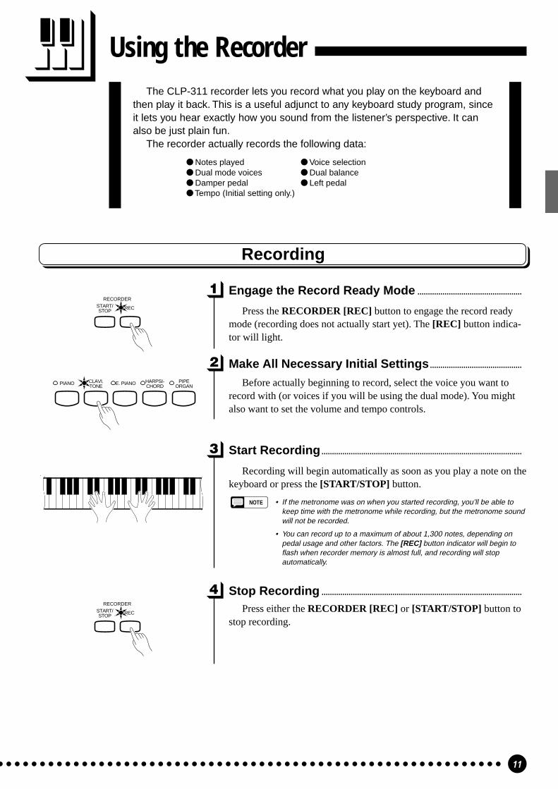
The CLP-311 recorder lets you record what you play on the keyboard andthen play it back. This is a useful adjunct to any keyboard study program, sinceit lets you hear exactly how you sound from the listener’s perspective. It canalso be just plain fun.
The recorder actually records the following data:
Notes played Voice selection Dual mode voices Dual balance Damper pedal Left pedal Tempo (Initial setting only.)
Using the Recorder
Press either the RECORDER [REC] or [START/STOP] button tostop recording.
Recording
Engage the Record Ready Mode ..................................................
Press the RECORDER [REC] button to engage the record readymode (recording does not actually start yet). The [REC] button indica-tor will light.
Make All Necessary Initial Settings............................................
Before actually beginning to record, select the voice you want torecord with (or voices if you will be using the dual mode). You mightalso want to set the volume and tempo controls.
Start Recording................................................................................................
Recording will begin automatically as soon as you play a note on thekeyboard or press the [START/STOP] button.
NOTE • If the metronome was on when you started recording, you’ll be able tokeep time with the metronome while recording, but the metronome soundwill not be recorded.
• You can record up to a maximum of about 1,300 notes, depending onpedal usage and other factors. The [REC] button indicator will begin toflash when recorder memory is almost full, and recording will stopautomatically.
Stop Recording ................................................................................................
PIANO E. PIANOCLAVI.TONE
HARPSI-CHORD
PIPEORGAN
RECSTART/STOP
RECORDER
RECSTART/STOP
RECORDER

12
Using the Recorder
Changing the Initial Settings.............................................................
The initial voice (including dual mode), damper pedal, soft pedal,and tempo settings made in step 2 of the recording procedure areactually recorded by the CLP-311. These initial settings can be changedafter the recording is finished by pressing the [REC] button to engagethe record ready mode, making the required changes, and then pressingthe [REC] button again to exit from the record ready mode and registerthe changes. If you do this, be careful not to press the [START/STOP]button or a key on the keyboard, either of which will start recording anderase all previous recorded data.
Erasing the recorded data ...................................................................
The recorded data can be erased by first pressing the [REC] buttonto engage the record ready mode, and then pressing the [START/STOP] button twice without recording any data.
Playback
To play back what you’ve recorded, simply press the RECORDER[START/STOP] button. Playback starts from the beginning of therecorded data, and will stop automatically at the end of the recordeddata. You can also stop playback at any time by pressing the [START/STOP] button.
NOTE • It is possible to play along on the keyboard during playback.
• The playback volume and tempo can be adjusted by using the [MASTERVOLUME] and [TEMPO] controls, respectively.
• If the metronome is being used during playback, the metronome will stopwhen playback is stopped.
• All recorder data will be erased when the CLP-311 power is turned off. Itis possible to store recorded data to an external MIDI storage devicesuch as the Yamaha DOU-10 Disk Orchestra Unit by using the BulkDump function described on page 16.
• The playback data is not transmitted via the MIDI OUT connector.
Fast Forward Playback ............................................................................
When you want to locate a specific point in a recording you canquickly move forward through the recording while monitoring thesound by pressing the [REC] button while holding the [MIDI/TRANS-POSE] button.
RECSTART/STOP
RECORDER
RECSTART/STOP
RECORDER
MIDI/TRANSPOSE
13
MIDI Functions
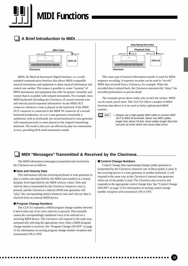
A Brief Introduction to MIDI...............................................................................................................................................
DOU-10
MIDI Cable
MIDI INMIDI OUT
Clavinova
DOU-10
Clavinova
Data Being Recorded
Playback Data
MIDI IN MIDI INMIDI OUTMIDI OUT
The MIDI information (messages) transmitted and received bythe Clavinova are as follows:
Note and Velocity DataThis information tells the receiving keyboard or tone generator to
play a certain note (specified by the MIDI note number) at a certaindynamic level (specified by the MIDI velocity value). Note andvelocity data is transmitted by the Clavinova whenever a key ispressed, and the Clavinova’s internal AWM tone generator will“play” the corresponding note(s) whenever note and velocity data isreceived from an external MIDI device.
Program Change NumbersThe CLP-311 transmits a MIDI program change number between
0 and 4 when one of its voice selectors is pressed. This normallycauses the correspondingly numbered voice to be selected on areceiving MIDI device. The Clavinova will respond in the same way,automatically selecting the appropriate voice when a MIDI programchange number is received. See “Program Change ON/OFF” on page15 for information on turning program change number reception andtransmission ON or OFF.
MIDI “Messages” Transmitted & Received by the Clavinova .......................................................
Control Change NumbersControl Change data representing Damper pedal operation is
transmitted by the Clavinova whenever one of these pedals is used. Ifthe receiving device is a tone generator or another keyboard, it willrespond in the same way as the Clavinova’s internal tone generatorwhen one of the pedals is used. The Clavinova also receives andresponds to the appropriate control change data. See “Control ChangeON/OFF” on page 15 for information on turning control changenumber reception and transmission ON or OFF.
MIDI, the Musical Instrument Digital Interface, is a world-standard communication interface that allows MIDI-compatiblemusical instruments and equipment to share musical information andcontrol one another. This makes it possible to create “systems” ofMIDI instruments and equipment that offer far greater versatility andcontrol than is available with isolated instruments. For example, mostMIDI keyboards (including the Clavinova, of course) transmit noteand velocity (touch response) information via the MIDI OUTconnector whenever a note is played on the keyboard. If the MIDIOUT connector is connected to the MIDI IN connector of a secondkeyboard (synthesizer, etc.) or a tone generator (essentially asynthesizer with no keyboard), the second keyboard or tone generatorwill respond precisely to notes played on the original transmittingkeyboard. The result is that you can effectively play two instrumentsat once, providing thick multi-instrument sounds.
This same type of musical information transfer is used for MIDIsequence recording. A sequence recorder can be used to “record”MIDI data received from a Clavinova, for example. When therecorded data is played back, the Clavinova automatically “plays” therecorded performance in precise detail.
The examples given above really only scratch the surface. MIDIcan do much, much more. The CLP-311 offers a number of MIDIfunctions that allows it to be used in fairly sophisticated MIDIsystems.
NOTE • Always use a high-quality MIDI cable to connect MIDIOUT to MIDI IN terminals. Never use MIDI cableslonger than about 15 feet, since cables longer than thiscan pick up noise which can cause data errors.

14
MIDI Functions
MIDI Transmit & Receive Channel Selection ..................................................................................................
Tone Generator
MIDI INMIDI IN MIDI THRU
DOU-10
MIDI OUT
Clavinova
Setting the Clavinova MIDI Channels
(Set to receive on MIDIchannel 2)
(Set to receive on MIDI channel 1)
C1 D#2 C4 D#5
1 3 5 6 8 10 12 13 15
2 4 7 9 11 14 16
1 3 5 6 8 10 12 13 15
2 4 7 9 11 14 16
E 5
MIDI/TRANSPOSE
For setting the transmitchannel. (C1 ~ D#2)
For setting the receivechannel. (C4 ~ D#5)
For OMNI mode
ZPress and hold the [MIDI/TRANSPOSE] button.
XPress the key on the keyboard corresponding to the desired MIDItransmit or receive channel.*
CRelease the [MIDI/TRANSPOSE] button.
* Keys C1 through D#2 on the keyboard are used to set the MIDItransmit channel, and keys C4 through D#5 are used to turn theOMNI mode OFF and set the MIDI receive channel as shown inthe illustration to the left. The E5 key sets the OMNI receivemode and basic receive channel 1.
NOTE • When the power is initially turned ON, MIDI receive isset to the OMNI mode and the transmit channel is setto 1.
The MIDI system allows transmission and reception of MIDI dataon 16 different channels. Multiple channels have been implementedto allow selective control of certain instruments or devices connectedin series. For example, a single MIDI sequence recorder could beused to “play” two different instruments or tone generators. One ofthe instruments or tone generators could be set to receive only onchannel 1, while the other is set to receive on channel 2. In thissituation the first instrument or tone generator will respond only tochannel-1 information transmitted by the sequence recorder, while thesecond instrument or tone generator will respond only to channel-2information. This allows the sequence recorder to “play” twocompletely different parts on the receiving instruments or tonegenerators.
In any MIDI control setup, the MIDI channels of the transmittingand receiving equipment must be matched for proper data transfer. An“OMNI” receive mode is also available, which allows reception onall 16 MIDI channels. In the OMNI mode it is not necessary to matchthe receive channel of the receiving device to the transmit channel ofthe transmitting device (except when receiving mode messages).
Other MIDI Functions
The MIDI functions listed to the right are engaged by holdingdown the [MIDI/TRANSPOSE] button and pressing the correspond-ing voice selector. Full details are given in the following pages.
Function CLP-311 Voice SelectorLocal Control ON/OFF [PIANO]Program Change ON/OFF [CLAVI. TONE]Control Change ON/OFF [E. PIANO]
Multi-Timbre Mode [HARPSICHORD]MIDI Split & Left Local OFF [PIPE ORGAN]
MIDI FUNCTION CHART
MIDI Transmit Transpose .....................................................................................................................................................
This function allows the MIDI note data transmitted by theClavinova to be transposed up or down in semitone increments by upto plus or minus 6 semitones. The pitch of the Clavinova itself is notaffected.
Setting the MIDI Transpose Function
MIDI/TRANSPOSEC6F#5 F#6
-6 -4 -2 +1 +3 +6
+5+4+20-1-3-5
ZPress and hold the [MIDI/TRANSPOSE] button.
XPress the key on the keyboard corresponding to the desiredamount of transposition.*
CRelease the [MIDI/TRANSPOSE] button.
* Keys F#5 through F#6 on the keyboard are used to set the MIDItransmit transpose function as shown in the illustration to the left.
NOTE • When the power is turned ON, MIDI transmit transposeis set to 0 (no transposition).

15
MIDI Functions
Local Control ON/OFF .............................................................................................................................................................
“Local Control” refers to the fact that, normally, the Clavinovakeyboard controls its internal tone generator, allowing the internalvoices to be played directly from the keyboard. This situation is“Local Control ON” since the internal tone generator is controlledlocally by its own keyboard.
Local control can be turned OFF, however, so that the Clavinovakeyboard does not play the internal voices, but the appropriate MIDIinformation is still transmitted via the MIDI OUT connector whennotes are played on the keyboard. At the same time, the internal tonegenerator responds to MIDI information received via the MIDI INconnector.
When using the DOU-10 Disk Orchestra Unit with the Clavinova,for example, Local Control should be turned OFF when recordingusing the DOU-10 voices only, and ON when recording theClavinova voices while listening to playback of the DOU-10 voices.
MIDI/TRANSPOSEPIANO CLTO PIANO
PIANO
= Local Control OFF
= Local Control ON
ZHold down the [MIDI/TRANSPOSE] button.
XPress the [PIANO] voice selector. If the PIANO LED is lit whenthe [PIANO] voice selector is pressed, you have turned localcontrol OFF. If the PIANO LED is not lit when the [PIANO]voice selector is pressed, you have turned local control ON.
CRelease the [MIDI/TRANSPOSE] button.
Control Change ON/OFF .......................................................................................................................................................
Normally the Clavinova will respond to MIDI control changedata received from an external MIDI device or keyboard, causing theselected Clavinova voice to be affected by pedal and other “control”settings received from the controlling device. The Clavinova alsotransmits MIDI control change information when one of its pedals areoperated.
This function makes it possible to cancel control change datareception and transmission if you do not want the Clavinova voices tobe affected by control change data received from an external deviceor vice versa.
E. PIANO HACH MIDI/TRANSPOSE E. PIANO
E. PIANO
= Control Change OFF
= Control Change ON
ZHold down the [MIDI/TRANSPOSE] button.
XPress the [E. PIANO] voice selector. If the E. PIANO LED is litwhen the [E. PIANO] voice selector is pressed, you have turnedcontrol change reception/transmission OFF. If the E. PIANOLED is not lit when the [E. PIANO] voice selector is pressed,you have turned control change reception/transmission ON.
CRelease the [MIDI/TRANSPOSE] button.
Program Change ON/OFF ....................................................................................................................................................
Normally the Clavinova will respond to MIDI program changenumbers received from an external keyboard or other MIDI device,causing the correspondingly numbered Clavinova voice to beselected. The Clavinova will normally also send a MIDI programchange number whenever one of its voices is selected, causing thecorrespondingly numbered voice or program to be selected on theexternal MIDI device if the device is set up to receive and respond toMIDI program change numbers.
This function makes it possible to cancel program change numberreception and transmission so that voices can be selected on theClavinova without affecting the external MIDI device, and vice versa.
NO E. PCLAVI.TONE MIDI/TRANSPOSE CLAVI.
TONE
CLAVI.TONE
= Program Change OFF
= Program Change ON
ZHold down the [MIDI/TRANSPOSE] button.
XPress the [CLAVI. TONE] voice selector. If the CLAVINOVATONE LED is lit when the [CLAVI. TONE] voice selector ispressed, you have turned program change reception/transmissionOFF. If the CLAVINOVA TONE LED is not lit when the[CLAVI. TONE] voice selector is pressed, you have turnedprogram change reception/transmission ON.
CRelease the [MIDI/TRANSPOSE] button.
16
MIDI Functions
The Multi-Timbre Mode...........................................................................................................................................................
The Multi-Timbre mode is a special mode in which the Clavinovavoices can be independently controlled on different MIDI channelnumbers by an external MIDI device. The Multi-Timbre mode can beactivated as follows:
NO HARPSI-CHORD
POR MIDI/TRANSPOSE HARPSI-
CHORD
HARPSI-CHORD
= Multi-Timbre Mode ON
= Multi-Timbre Mode OFF
ZHold down the [MIDI/TRANSPOSE] button.
XPress the [HARPSICHORD] voice selector. If the HARPSI-CHORD LED is lit when the [HARPSICHORD] voice selectoris pressed, you have turned the Multi-Timbre mode ON. If theHARPSICHORD LED is not lit when the [HARPSICHORD]voice selector is pressed, you have turned the Multi-Timbre modeOFF.
CRelease the [MIDI/TRANSPOSE] button.
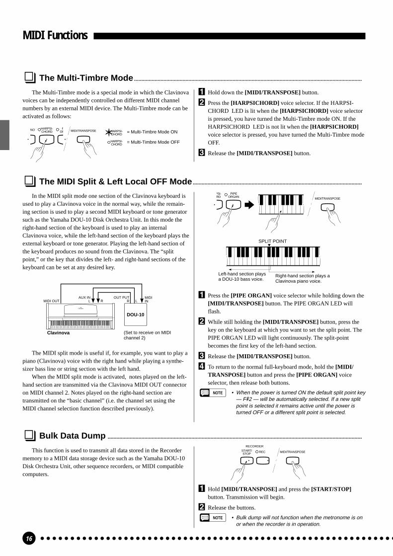
The MIDI Split & Left Local OFF Mode...................................................................................................................
In the MIDI split mode one section of the Clavinova keyboard isused to play a Clavinova voice in the normal way, while the remain-ing section is used to play a second MIDI keyboard or tone generatorsuch as the Yamaha DOU-10 Disk Orchestra Unit. In this mode theright-hand section of the keyboard is used to play an internalClavinova voice, while the left-hand section of the keyboard plays theexternal keyboard or tone generator. Playing the left-hand section ofthe keyboard produces no sound from the Clavinova. The “splitpoint,” or the key that divides the left- and right-hand sections of thekeyboard can be set at any desired key.
SPLIT POINT
Left-hand section playsa DOU-10 bass voice.
Right-hand section plays aClavinova piano voice.
MIDI/TRANSPOSE
PSI-RD
PIPEORGAN
ZPress the [PIPE ORGAN] voice selector while holding down the[MIDI/TRANSPOSE] button. The PIPE ORGAN LED willflash.
XWhile still holding the [MIDI/TRANSPOSE] button, press thekey on the keyboard at which you want to set the split point. ThePIPE ORGAN LED will light continuously. The split-pointbecomes the first key of the left-hand section.
CRelease the [MIDI/TRANSPOSE] button.
VTo return to the normal full-keyboard mode, hold the [MIDI/TRANSPOSE] button and press the [PIPE ORGAN] voiceselector, then release both buttons.
NOTE • When the power is turned ON the default split point key— F#2 — will be automatically selected. If a new splitpoint is selected it remains active until the power isturned OFF or a different split point is selected.
Bulk Data Dump .............................................................................................................................................................................
This function is used to transmit all data stored in the Recordermemory to a MIDI data storage device such as the Yamaha DOU-10Disk Orchestra Unit, other sequence recorders, or MIDI compatiblecomputers.
MIDI/TRANSPOSERECSTART/STOP
RECORDER
ZHold [MIDI/TRANSPOSE] and press the [START/STOP]button. Transmission will begin.
XRelease the buttons.
NOTE • Bulk dump will not function when the metronome is onor when the recorder is in operation.
DOU-10
OUT PUTR L
AUX INL RMIDI OUT
MIDIIN
Clavinova (Set to receive on MIDIchannel 2)
The MIDI split mode is useful if, for example, you want to play apiano (Clavinova) voice with the right hand while playing a synthe-sizer bass line or string section with the left hand.
When the MIDI split mode is activated, notes played on the left-hand section are transmitted via the Clavinova MIDI OUT connectoron MIDI channel 2. Notes played on the right-hand section aretransmitted on the “basic channel” (i.e. the channel set using theMIDI channel selection function described previously).
17
TroubleshootingIf you encounter what appears to be a malfunction, please check the follow-
ing points before assuming that your Clavinova is faulty.
1. No Sound When the Power is Turned ONIs the AC plug properly connected to the Clavinova and an AC wall outlet? Check the AC connection
carefully. Is the MASTER VOLUME control turned up to a reasonable listening level?Also make sure that a pair of headphones is not plugged into the PHONES jack, and the Local Control
(page 15) is ON.
2. The Damper Pedal Doesn’t WorkIf the damper pedal doesn’t work, or notes are sustained even when the pedal is not pressed, make sure
that the pedal cord is properly plugged into the main unit (page iii).
3. The Clavinova Reproduces Radio or TV SoundThis can occur if there is a high-power transmitter in your vicinity. Contact your Yamaha dealer.
4. Intermittent Static NoiseThis is usually due to turning ON or OFF a household appliance or other electronic equipment which is
fed by the same AC mains line as your Clavinova.
5. Interference Appears On Radio or TV Sets Located Near the ClavinovaThe Clavinova contains digital circuitry which can generate radio-frequency noise. The solution is to
move the Clavinova further away from the affected equipment, or vice versa.
6. Distorted Sound When the Clavinova is Connected to An External Amplifier/Speaker SystemIf the Clavinova is connected to a stereo system or instrument amplifier and the sound is distorted,
reduce the setting of the Clavinova volume control to a level at which the distortion ceases.
Options & Expander Modules
OptionsBC-8 Bench
A comfortable bench styled to match your Yamaha Clavinova.
HPE-160 Stereo HeadphonesHigh-performance lightweight dynamic headphones with extra-soft ear pads.
KC-883 Key CoverA convenient way to keep your keyboard clean and dust-free.
Expander Modules
DOU-10 Disk Orchestra Unit
A range of MIDI recording and playback functions, plus Yamaha Disk Orchestra Collection, DisklavierPianoSoft™, General MIDI, and Standard MIDI File disk playback capability.

1
i
NOTE • We do not recommend attempting to assemble theClavinova alone. The job can be easily accomplished,however, with only two people.
• Use only the screws provided or replacements ofexactly the specified size. Using screws of the wrongsize can result in damage to the instrument.
ZOpen the box and remove all the parts.On opening the box you should find the parts shown in the
illustration above. Check to make sure that all the required partsare provided.
XAttach the side panels (D) to the pedal box(C).
Before installing the pedal box, untie and straighten out thebundled cord attached to the bottom of the pedal box. Don’t dis-card the vinyl tie, you’ll need it later in step B.
Place the pedal box on top of the wooden blocks attached tothe side panels (D), and attach using the four 6 x 35 millimeterround-head screws 1 — two screws on each side. Make sure thepedals extend in the same direction as the feet.
CAttach the center panel (B) to the side pan-els (D).
The center panel (B) is installed between the side panels (D)with the brackets on each end toward the rear of the stand assem-bly. Place the square holes in the center-panel brackets over thelugs extending from the side panels, then slide down. Each sideof the center panel is attached using two 6 x 16 flat-head screws2.
HINWEIS • Wir raten davon ab, das Clavinova alleine zusammenzu-bauen und aufzustellen. Zwei Personen können dieseArbeit jedoch problemlos ausführen.
• Verwenden Sie ausschließlich die mitgelieferten Schrau-ben oder Ersatzschrauben identischer Größe. Die Ver-wendung von Schrauben mit abweichenden Maßen kanneine Beschädigung des Instruments zur Folge haben.
ZÖffnen Sie den Karton und nehmen Sie alleTeile heraus.
Im Karton sollten die oben abgebildeten Teile enthalten sein.Prüfen Sie zunächst bitte, ob alle Teile vollständig vorhanden sind.
XSchrauben Sie den Pedalkasten (C) an denSeitenwänden (D) fest.
Bevor Sie den Pedalkasten montieren, nehmen Sie zunächst dasgebündelte Kabel aus dem Pedalkasten, entfernen den Kabelbinderund ziehen das Kabel dann gerade aus. Werfen Sie den Kabelbindernicht wg, er wird in Schritt B wieder gebraucht.
Setzen Sie den Pedalkasten auf die Holzklötze an den Seiten-wänden (D), und schrauben Sie ihn dann mit den vier 6 x 35 mmHalbrundschrauben 1 fest (jeweils zwei Schrauben links undrechts). Achten Sie dabei darauf, daß die Pedale in dieselbe Rich-tung weisen wie die vorspringenden Teile der Füße.
CSchrauben Sie die Rückwand (B) an die bei-den Seitenwände (D).
Die Rückwand (B) wird mit den Winkelblechen an beiden Endennach hinten weisend an den Seitenwänden (D) befestigt. Lassen Siedabei die Führungsnasen an den Seitenwänden in dieSchlitzbohrungen in den beiden Winkelblechen greifen, und drückenSie die Rückwand dann nach unten. Sichern Sie die Rückwand dannmit jeweils zwei kurzen schwarzen Schrauben 2 an den Seiten-wänden.
Zusammenbau und AufstellungKeyboard Stand Assembly
Bundled pedal cord insideGebündeltes PedalkabelCordon de pédalier enroulé à l’intérieurCable de pedales enrollado en el interior
AC power cord Netzkabel Cordon d’alimentation Cable de alimentación de CA
6 x 35 mm round-head screws x 4 16 x 35 mm Halbrundschrauben x 4 1Vis à tête ronde de 6 x 35 mm x 4 1Tornillos de cabeza redondade 6 x 35 mm x 4 1
6 x 16 mm flat-head screws x 8 26 x 16 mm Senkschrauben x 8 2Vis à tête plate de 6 x 16 mm x 8 2Tornillos de cabeza plana de6 x 16 mm x 8 2
A
B
C
D

2 3
ii
Assemblage du support de clavierREMARQUE • Nous ne vous conseillons pas d’essayer d’assembler
le Clavinova seul. Toutefois, ce travail peut être facile-ment exécuté par deux personnes.
• N’utilisez que les vis fournies ou des vis ayant exacte-ment les mêmes dimensions. L’utilisation de vis dedimensions incorrectes pourrait endommager l’instru-ment.
ZOuvrez le carton et retirez toutes les piècesLes pièces indiquées sur l’illustration devraient toutes se trou-
ver dans le carton. Vérifiez qu’il n’en manque aucune.
XFixez les panneaux latéraux (D) au pédalier(C)
Avant de poser le pédalier, détacher le cordon de la partieinférieure du pédalier et le dérouler. Ne jetez pas l’attache envinyle, vous la réutiliserez ultérieurement à l’étape B.
Placez le pédalier sur les cales en bois fixées aux panneauxlatéraux (D) et fixez-le à l’aide des quatre vis à tête ronde de 6 x35 millimètres 1: deux vis de chaque côté. Veillez à ce que lespédales soient dirigées dans le même sens que les supports infé-rieurs.
CFixez le panneau central (B) aux panneauxlatéraux (D)
Le panneau central (B) doit être posé entre les panneaux laté-raux (D) en prenant soin de diriger la ferrure située à chaqueextrémité vers l’arrière du support. Placez les orifices carrés desferrures du panneau central sur les languettes dépassant des pan-neaux latéraux et faites glisser vers le bas. Chaque côté du pan-neau central doit être fixé à l’aide de deux vis courtes noires 2.
Conjunto del soporte del tecladoNOTA • No le recomendamos que intente montar la Clavinova
usted solo. El trabajo puede ser realizado fácilmenteentre dos personas.
• Utilice sólo los tornillos suministrados o reemplazos delexacto tamaño especificado. El empleo de tornillos deun tamaño erróneo puede dañar el instrumento.
ZAbra la caja y extraiga todas las partes.Al abrir la caja deberá encontrar todas las partes mostradas en
la ilustración. Compruebe para asegurarse que se proporcionantodas las partes necesarias.
XAcople los paneles laterales (D) en la cajade pedales (C).
Antes de instalar la caja de pedales, desate y enderezca elcable plegado unido a la parte inferior de la caja de pedales. Notire la abrazadera de vinilo, porque la necesitará en el paso B demás adelante.
Ponga la caja de pedales encima de los bloques de maderaunidos a los paneles laterales (D), y acople empleando los cuatrotornillos de cabeza redonda de 6 x 35 mm 1; dos tornillos encada lado. Asegúrese de que el pedal se extiende en la mismadirección que la pata.
CAcople el panel central (B) en los paneleslaterales (D).
El panel central (B) se instala entre los paneles laterales (D)con las ménsulas de cada extremo encaradas hacia la parte poste-rior del conjunto del soporte. Coloque los orificios cuadrados delas ménsulas del panel central por encima de las lengüetas que seextienden desde los paneles laterales, después deslice hacia abajo.Cada lado del panel central se acopla usando dos tornillos negroscortos 2.
D
6 x 35 mm round-head screws 16 x 35 mm Halbrundschrauben 1Vis à tête ronde de 6 x 35 mm 1Tornillos de cabeza redonda de 6 x 35 mm 1
6 x 16 mm flat-head screws 26 x 16 mm Senkschrauben 2Vis à tête plate de 6 x 16 mm 2Tornillos de cabeza plana de 6 x 16 mm 2
B
C
CD

4
iii
VMontieren Sie die Tastatureinheit (A).Setzen Sie die Tastatureinheit (A) so auf den fertigen Ständer,
daß die beiden Schrauben an ihrer Unterseite hinter den Winkel-blechen mit Führungsschlitz an der Hinterseite des Ständers zuliegen kommen. Schieben Sie die Tastatureinheit dann bis zumAnschlag in die Schlitze. KLEMMEN SIE IHRE FINGER DA-BEI NICHT EIN!!
Richten Sie die Schraubenbohrungen an der Unterseite derTastatureinheit mit den Bohrungen der Winkelbleche aus (achtenSie auch darauf, daß sie mittig auf dem Ständer steht, wie in derAbbildung gezeigt). Schrauben Sie die Tastatureinheit dann mit denvier 6 x 16 mm Senkschrauben 2 am Ständer fest.
BSchließen Sie das Pedalkabel an.Sichern Sie das Pedalkabel in den beiden Kabelhaltern an den
Seitenwänden. Der Stecker wird an die zugehörige Buchse an derUnterseite der Tastatureinheit (A) angeschlossen. Der Stecker paßt nurin einer Richtung in die Buchse (mit der Führungsnase zur Tastaturseitedes Instruments weisend — siehe Abbildung). Versuchen Sie nicht, denStecker falsch herum mit Gewalt in die Buchse zu drücken!
NDen Spannungswähler einstellen.Bevor Sie nun das Netzkabel anschließen, müssen Sie den
Spannungswähler (falls vorhanden) auf die örtliche Netzspannungeinstellen. Zum Verstellen drehen Sie den Spannungswähler miteinem Schlitzschraubendreher, bis der richtige Spannungswert (110,127, 220 oder 240) an der Pfeilmarkierung steht. Bei der Ausliefe-rung werden alle Instrumente mit Spannungswähler auf “240” vor-eingestellt.
Nachdem Sie den Spannungswähler richtig eingestellt haben,können Sie nun das Netzkabel anschließen. In manchen Gebietenwird ein Steckerdapter mitgeliefert, um den Anschluß an die evtl.unterschiedlich geformte Steckdose zu ermöglichen.
MJustieren Sie schließlich noch den Höhen-versteller.
Zur Stabilisierung ist an der Unterseite des Pedalkastens (C) einHöhenversteller vorgesehen. Schrauben Sie den Höhenverstellerheraus, bis er fest auf dem Fußboden steht. Der Höhenverstellersorgt für stabile Pedalbetätigung und ermöglicht eine präzise Rege-lung des Betätigungshubs. Wenn er nicht fest auf dem Boden steht,können beim Treten der Pedale Klangverzerrungen auftreten.
WICHTIG • Vergewissern Sie sich nach Zusammenbau und Aufstel-lung des Clavinova noch einmal davon, daß alle Schrau-ben fest angezogen sind.
• Wenn der Ständer schief steht, komische Geräuscherzeugt oder sich beim Spielen wackelig anfühlt, prüfenSie gemäß den unter “Zusammenbau und Aufstellung”gegebenen Anweisungen, ob der Ständer richtigzusammengebaut wurde, und ziehen dabei die einzelnenSchrauben noch einmal nach.
V Install the main unit (A).Place the main unit (A) on the side panels (D) with the screws
on its bottom panel (toward the rear of the main unit) just behindthe grooves in the brackets located at the top of the side panels.Then slide the main unit forward until it stops. WATCH YOURFINGERS WHEN DOING THIS!!
Align the holes on the bottom panel of the main unit with theholes in the brackets on the side panels (also center the main unitto produce equal clearance on the left and right sides, as shown inthe illustration), then screw in and securely tighten the four 6 x16 millimeter flat-head screws 2.
BConnect the pedal cord.Pass the pedal cord through the two cord holders on the side
panel. Plug the free end of the cord into the connector on thebottom of the main unit (A). The plug only goes in one way (thelug on the connector should face the keyboard-side of the mainunit, as shown in the illustration) — don’t try to force it in thewrong way around.
NVoltage SelectorBefore connecting the AC power cord, check the setting of the
voltage selector which is provided in some areas. To set the se-lector for 110V, 127V, 220V or 240V main voltages, use a “mi-nus” screwdriver to rotate the selector dial so that the correctvoltage for your region appears next to the pointer on the panel.The voltage selector is set at 240V when the unit is initiallyshipped.
After the proper voltage has been selected connect the ACpower cord. A plug adaptor may be also provided in some areasto match the pin configuration of the AC wall outlets in yourarea.
MSet the adjuster.For stability, an adjuster is provided on the bottom of the
pedal box (C). Rotate the adjuster until it comes in firm contactwith the floor surface. The adjuster ensures stable pedal operationand facilitates pedal effect control. If the adjuster is not in firmcontact with the floor surface, distorted sound may result.
IMPORTANT • After assembling the Clavinova, check once more tomake sure that all screws have been securely fas-tened.
• If the stand leans to the side, makes unusual noises, orotherwise seems unstable during use, check andtighten all screws while following the assembly instruc-tions given above.
Danger ZoneGefahrenzoneZones dangereusesZona peligrosa
6 x 16 mm flat-head screws 26 x 16 mm Senkschrauben 2Vis à tête plate de 6 x 16 mm 2Tornillos de cabeza plana de 6 x 16 mm 2
A
D
D
A

5
iv
VPosez le clavier (A)Placez le clavier sur les panneaux latéraux (D), avec les vis de
son panneau inférieur (situées vers l’arrière du clavier) placéesimmédiatement derrière les rainures des ferrures situées à lapartie supérieure des panneaux latéraux (D), puis faites glisser leclavier vers l’avant jusqu’à ce qu’il vienne en butée. FAITESATTENTION A VOS DOIGTS EN EXECUTANT CETTEOPERATION!!
Alignez les trous du panneau inférieur du clavier sur les trousdes ferrures des panneaux latéraux (centrez également le clavierde manière à avoir un jeu identique de chaque côté) puis posez etserrez à fond les quatre vis à tête plate de 6 x 16 millimètres 2.
BConnectez le cordon du pédalierFaites passer le cordon du pédalier dans les deux supports de
cordon situés sur le panneau latéral. La prise doit être branchéeau connecteur correspondant situé à la partie inférieure du clavier(A). La prise ne peut être branchée que dans un seul sens (lalanguette de la prise doit être dirigée vers l’avant du clavier,comme montré sur l’illustration) et n’essayez donc pas de laforcer pour la mettre en place du mauvais côté.
NSélecteur de tensionAvant de connecter le cordon d’alimentation, vérifiez le ré-
glage du sélecteur de tension qui est prévu pour certaines régions.Pour régler le sélecteur sur 110 V, 127 V, 220 V ou 240 V, utili-sez un tournevis à lame plate pour tourner le cadran du sélecteurafin de mettre l’indication correspondant à la tension de votrerégion vis à vis du repère triangulaire situé sur le panneau. Lesélecteur de tension est réglé sur 240 V au départ d’usine.
Une fois que vous avez réglé le sélecteur de tension, connectezle cordon d’alimentation. Un adaptateur de prise peut égalementêtre fourni dans certaines régions pour pouvoir brancher le cor-don à la prise secteur murale.
MN’oubliez pas de régler la hauteur du péda-lier
Pour assurer la stabilité du pédalier (C), un dispositif de réglage aété prévu à sa partie inférieure. Tournez ce dispositif jusqu’à cequ’il soit en contact ferme avec la surface du sol. Ce dispositif as-sure la stabilité du pédalier lors de son utilisation et facilite la com-mande au pied des effets. Si ce dispositif n’est pas en contact fermeavec le sol, il pourra se produire une distorsion du son.
IMPORTANT • Après avoir assemblé le Clavinova, vérifiez une fois deplus que toutes les vis sont bien serrées.
• Si le support du clavier penche d’un côté, fait du bruitou semble instable lorsque vous utilisez l’instrument,vérifiez de nouveau et resserrez toutes les vis ensuivant les instructions d’assemblage données ci-dessus.
V Instale la unidad principal (A).Coloque la unidad principal en los paneles laterales (D) con
los tornillos de su panel inferior (hacia la parte posterior de launidad principal) justo detrás de las ranuras de la ménsula ubica-da en la parte superior de los paneles laterales (D), después desli-ce el teclado hacia adelante hasta que se pare. ¡TENGA CUIDA-DO CON SUS DEDOS MIENTRAS LO HACE!
Alinee los orificios del panel inferior de la unidad principalcon los orificios de las ménsulas de los paneles laterales (tambiéncentre la unidad principal para producir una holgura igual en loslados derecho e izquierdo, como se muestra en la ilustración),después enrosque y apriete bien los cuatro tornillos de cabezaplana de 6 x 16 mm 2.
BConecte el cable de los pedales.Pase el cable de los pedales a través de los dos soportes de cable
del panel lateral. La clavija puede enchufarse en el conector corres-pondiente de la parte inferior de la unidad principal (A). La clavija seenchufa sólo en una dirección (la lengüeta del conector debe estarencarada hacia el lado del teclado de la unidad principal, como semuestra en la ilustración), por eso no la fuerce en la dirección errónea.
NSelector de tensiónAntes de conectar el cable de alimentación de CA, compruebe
el ajuste del selector de tensión que se incorpora para ciertosdestinos. Para ajustar el selector a 110V, 127V, 220V ó 240V dela red de alimentación, emplee un destornillador de cabeza recta“-” para girar el selector de modo que la tensión correcta de suzona aparezca al lado del indicador del panel. El selector detensión se ajusta a 240V cuando la unidad sale de fábrica.
Después de haber seleccionado la tensión correcta, enchufe elcable de alimentación. En algunas zonas puede suministrarsetambién un adaptador para adaptar la configuración de las patillasde los tomacorrientes de CA de su localidad.
MAsegúrese de ajustar el ajustador.Para la estabilidad del aparato, se proporciona un ajustador en
la parte inferior de la caja de pedales (C). Gire el ajustador hastaque contacte firmemente con el suelo. El ajustador asegura unaoperación estable de los pedales y facilita el control del efecto delos pedales. Si el ajustador no contacta firmemente con el suelo,puede resultar en sonido distorsionado.
IMPORTANTE • Después de montar la Clavinova, compruebe otra vezpara asegurarse de que todos los tornillos se hanapretado bien.
• Si el soporte se inclina hacia un lado, hace ruidosanormales, o parece inestable durante la utilización,compruebe y apriete todos los tornillos mientras siguelas instrucciones de montaje de arriba.
6
7 C
240
127
110 220
A voltage selector isprovided in some areas.
Spannungswähler(nur in bestimmtenVerkaufsgebieten)
Un sélecteur detension est prévu pourcertaines régions
El selector detensión está provistopara ciertos destinos.
A
A
A
Cord holderKabelhalterSupport de cordonSoporte del cable
Use the vinyl tiethat was re-moved from thebundled pedalcord in step Xto tie up anyslack in thepedal cord.
Nehmen Sie über-langes Kabel mitdem in Schritt XentferntenKabelbinder auf.
Utilisez l’attache envinyle qui a étéenlevée du cordonde pédalier à l’étapeX pour attacher lefil excédentaire ducordon de pédalier.
Emplee laabrazadera de viniloque se sacó del caleplegado de lospedales en el pasoX para fijar elcable de pedalessobrante.
Si vous êtes très familier avec l’interface MIDI ou si vousutilisez un ordinateur pour commander votre matériel demusique au moyen de messages MIDI générés par ordinateur,les données suivantes vous seront utiles et vous aideront àcommander le Clavinova.
SI usted está ya familiarizado con MIDI, o si emplea unacomputadora para controlar sus aparatos musicales conmensajes MIDI generados por computadora, los datos propor-cionados en esta sección le ayudarán a controlar la Clavinova.
1. NOTE ON/OFFData format: [9nH] -> [kk] -> [vv]9nH = Note ON/OFF event (n = channel number)kk = Note number
Transmit: 15 ~ 114 = D#-1 ~ F#7Receive: 21 ~ 108 = A-1 ~ C7
vv = Velocity (Key ON = 1 ~ 127. Key OFF = 0)
Data format: [8nH] -> [kk] -> [vv]8nH = Note OFF event (n = channel number)kk = Note number
Transmit: 15 ~ 114 = D#-1 ~ F#7Receive: 21 ~ 108 = A-1 ~ C7
vv = Velocity (Key OFF = 0 ~ 127)* 8nH (note off) is receive only.
9nH (vvH=00H) used for transmission.
2. CONTROL CHANGE & MODE MESSAGESData format: [BnH] -> [cc] -> [vv]BnH = Control event (n = channel number)cc = Control numbervv = Control valuecc CONTROL VALUE [vv]07H Volume 00000000 : -∞
(reception only) 01101111 : -3dB01111111 : ±0dB
0BH Expression 00000000 : -∞(reception only) 01101111 : -3dB
01111111 : ±0dB40H Damper 00H ~ 3FH : OFF
Pedal 40H ~ 7FH : ON42H Sostenuto 00H ~ 3FH : OFF
Pedal 40H ~ 7FH : ON43H Soft Pedal 00H ~ 3FH : OFF
40H ~ 7FH: ON78H All Sound OFF (reception only) 00H79H Reset All Controller (reception only) 00H7AH Local Control ON/OFF 00H : OFF
(reception only) 7FH : ON7BH All Notes OFF (reception only) 00H7CH Omni OFF/All Notes OFF 00H
(reception only)7DH Omni ON/All Notes OFF 00H
(reception only)
3. PROGRAM CHANGEData format: [CnH] -> [pp]CnH = program event (n = channel number)pp = Program numberpp VOICE NAME pp VOICE NAME00 PIANO 03 HARPSICHORD01 CLAVINOVA TONE 04 PIPE ORGAN02 E. PIANO
4. SYSTEM REALTIME MESSAGES[rrH]F8H: Timing clockFAH: StartFCH: StopFEH: Active sensing
Data Transmission ReceptionF8H Transmitted every Received as 96-clock
96 clocks tempo timing whenMIDI clock is set toExternal
FAH Recorder start Recorder startFCH Recorder stop Recorder stopFEH Transmitted every All notes are turned
200 milliseconds off if no data isreceived for more than400 milliseconds
If you’re already very familiar with MIDI, or are using a com-puter to control your music hardware with computer-generatedMIDI messages, the data provided in this section can help youto control the Clavinova.
Falls Sie bereits mit MIDI vertraut sind oder einen Computerzur Erzeugung von MIDI-Steuermeldungen für die Instrumenteverwenden, können Sie sich zur Steuerung des Clavinovas nachden im folgenden Abschnitt aufgeführten Spezifikationen richten.
MIDI Data Format/MIDI-Datenformat/Format des données MIDI/Formato de datos MIDI
(4) Absolute TempoData format: [F0H] -> [43H] -> [73H] -> [xx]-> [11H] -> [1nH] -> [cc] -> [dd] -> [F7H]43H : Yamaha ID73H : Clavinova IDxx : 38H (CLP-311 ID)11H : Clavinova special control1nH : Control MIDI change
(Transmit: n=control channel number)(Receive: any channel OK)
ccH : Absolute tempo low byteddH : Absolute tempo hight byte
Tempo=dd*128+cc
PANEL DATA SEND FORMATF0H, 43H, 0nH, 7CH, 00H, 1BH (n: channel number)53H, 4BH, 20H, 20H (SK)43H, 4CH, 50H, 27H, 39H, 34H (CLP)3xH, 3yH (x, y: version number)[PANEL DATA][CHECK SUM (1byte)] = 0-(53H+4BH+20H+...+Data end)F7H
• Panel Data Contents(1) VOICE(2) DUAL VOICE(3) DUAL ON/OFF(4) DUAL BALANCE(5) 0(6) 0(7) 0(8) 0(9) 0(10) 0(11) LEFT PEDAL (SOFT or SOSTENUTO)(12) SPLIT POINT(13) 0(14) Absolute tempo low byte(15) Absolute tempo high byte
MODEL ID CODE SEND FORMATF0H, 43H, 0nH, 7DH, 00H, 10H (n: channel number)53H, 4BH, 20H, 20H (SK)43H, 4CH, 50H, 27H, 39H, 34H (CLP)3xH, 3yH, 20H, 20H, 20H, 20H (x, y: version number)[CHECK SUM (1byte)] = 0-(53H+4BH+20H+......+20H)F7H
BULK DUMP FORMATF0H, 43H, 73H38H (Product ID: CLP-311)06H (Bulk ID)02H (Bulk number)03H, 0fH, 0aH, 02H (Data length= wxyzH 0x1fd1*2 bytes)[BULK DATA] (Sequence data)[CHECK SUM (1byte)] = 0-sum (BULK DATA)F7H
5. SYSTEM EXCLUSIVE MESSAGES(1) YAMAHA MIDI FormatData format: [F0H] -> [43H] -> [xn] -> [ff] ... [F7H]43H : Yamahaxn : Substatus + channel number.ff : Format number.x ff Information0 7CH Panel Data receive.2 7CH Panel Data Send occurs when this data received.2 7DH Name Data Send occurs when this data received.
(2) Clavinova MIDI FormatData format: [F0H] -> [43H] -> [73H] -> [xx]-> [yy] -> [F7H]43H : Yamaha ID73H : Clavinova IDxx : 38H (CLP-311 ID)yy : Substatusyy Information02H Internal MIDI clock.03H External MIDI clock.13H Multi-timbre mode OFF.15H Multi-timbre mode ON.61H MIDI FA cancel ON.62H MIDI FA cancel OFF.7cH All notes OFF; receive channel = c+1; omni OFF.* When yy=2, 3, 13, 15 or 7c, Clavinova common
ID (01H) is recognized as well as 38H.* All Control Change values are reset when [13H] or
[15H] is received. All voices and other parametersare also reset when [15H] is received in order toensure the same initial settings.
(3) Special ControlData format: [F0H] -> [43H] -> [73H] -> [xx]-> [11H] -> [0nH] -> [cc] -> [vv] -> [F7H]43H : Yamaha ID73H : Clavinova IDxx : 38H (CLP-311 ID)11H : Clavinova special control0nH : Control MIDI change + channel numbercc : Control numbervv : Valuecc Control Value [vv]08H Dual Balance 00H : Left Voice Max.
7FH : Right Voice Max.1BH Metronome 00H : Off
01H : On5AH Dual Mode 00H : Dual Off
01H : Dual On (Normal)02H : Dual On (Left voice 1
octave up)03H : Dual On (Right voice 1
octave up)5CH Dual Voice [vv] : Dual Voice
CLP-311KEYBOARD 88 KEYS (A-1 ~ C7)POLYPHONY 28 NOTES MAX.VOICE SELECTORS PIANO, CLAVINOVA TONE, E. PIANO, HARPSICHORD, PIPE ORGANRECORDER START/STOP, RECPEDAL CONTROLS SOFT/SOSTENUTO, DAMPEROTHER CONTROLS MASTER VOLUME, TEMPO, METRONOME, DEMO, MIDI/TRANSPOSEJACKS/CONNECTORS PHONES x 2, AUX OUT L/L+R & R, AUX IN L&R, MIDI IN/OUTINPUT & OUTPUT AUX OUT: Output impedance 600 ΩLEVEL/IMPEDANCE AUX IN: Input impedance 10 kΩ/ Input sensitivity -10 dBmMAIN AMPLIFIERS 20W x 2SPEAKERS 16 cm x 2DIMENTIONS Music stand 1375.2 x 525.0 x 842.6 mm(W x D x H) down (54-1/8" x 20-5/8" x 33-1/8")
Music stand 1375.2 x 525.0 x 1017.6 mm up (54-1/8" x 20-5/8" x 40-1/16")
WEIGHT 57.5 kg (126.8 lbs.)
* Specifications subject to change without notice.* Änderungen ohne Vorankündigung vorbehalten.
* Sous toute réserve de modification des caractéristiques sans préavis.* Especificaciones sujetas a cambios sin previo aviso.
Specifications/Technische Daten/Caractéristiques techniques/Especificaciones
* Caution: If an overrun framing error occurs theDamper, Sostenuto, and Soft effects for all chan-nels are turned off and an All Note Off occurs.
v

M.D.G., EMI Division © Yamaha Corporation 1996
VU32350 603POCP5.3-01A0 Printed in Japan
FCC INFORMATION (U.S.A.)1. IMPORTANT NOTICE: DO NOT MODIFY THIS UNIT!
This product, when installed as indicated in the instructions con-tained in this manual, meets FCC requirements. Modifications notexpressly approved by Yamaha may void your authority, grantedby the FCC, to use the product.
2. IMPORTANT: When connecting this product to accessories and/or another product use only high quality shielded cables. Cable/ssupplied with this product MUST be used. Follow all installationinstructions. Failure to follow instructions could void your FCCauthorization to use this product in the USA.
3. NOTE: This product has been tested and found to comply withthe requirements listed in FCC Regulations, Part 15 for Class “B”digital devices. Compliance with these requirements provides areasonable level of assurance that your use of this product in aresidential environment will not result in harmful interference withother electronic devices. This equipment generates/uses radiofrequencies and, if not installed and used according to the instruc-tions found in the users manual, may cause interference harmfulto the operation of other electronic devices. Compliance with FCC
regulations does not guarantee that interference will not occur inall installations. If this product is found to be the source of inter-ference, which can be determined by turning the unit “OFF” and“ON”, please try to eliminate the problem by using one of thefollowing measures:Relocate either this product or the device that is being affected bythe interference.Utilize power outlets that are on different branch (circuit breakeror fuse) circuits or install AC line filter/s.In the case of radio or TV interference, relocate/reorient the an-tenna. If the antenna lead-in is 300 ohm ribbon lead, change thelead-in to co-axial type cable.If these corrective measures do not produce satisfactory results,please contact the local retailer authorized to distribute this typeof product. If you can not locate the appropriate retailer, pleasecontact Yamaha Corporation of America, Electronic Service Divi-sion, 6600 Orangethorpe Ave, Buena Park, CA90620The above statements apply ONLY to those products distributedby Yamaha Corporation of America or its subsidiaries.
* This applies only to products distributed by YAMAHA CORPORATION OF AMERICA.
• This applies only to products distributed by Yamaha-Kemble Music (U.K.) Ltd.
IMPORTANT NOTICE FOR THE UNITED KINGDOMConnecting the Plug and Cord
IMPORTANT. The wires in this mains lead are coloured in accor-dance with the following code:
BLUE : NEUTRALBROWN : LIVE
As the colours of the wires in the mains lead of this apparatus maynot correspond with the coloured makings identifying the terminalsin your plug proceed as follows:The wire which is coloured BLUE must be connected to the termi-nal which is marked with the letter N or coloured BLACK.The wire which is coloured BROWN must be connected to theterminal which is marked with the letter L or coloured RED.Making sure that neither core is connected to the earth terminal ofthe three pin plug.
CAUTION: TO PREVENT ELECTRIC SHOCK, MATCH WIDEBLADE OF PLUG TO WIDE SLOT, FULLY INSERT.
ATTENTION: POUR ÉVITER LES CHOCS ÉLECTRIQUES,INTRODUIRE LA LAME LA PLUS LARGE DE LA FICHE DANS LABORNE CORRESPONDANTE DE LA PRISE ET POUSSER JUSQU’AUFOND.
• This applies only to products distributed by Yamaha Canada Music Ltd.• Ceci ne s’applique qu’aux produits distribués par Yamaha Canada Musique Ltée.