important safety instructions - graco 3 plastic parts cleaning solvent hazard use only compatible...
TRANSCRIPT

313385B
Repair and Parts
GTX™ 2000EX- For Water-Based Materials Only-
Model: 257030Sprayer with Graco Trigger Gun120 psi (8.27 bar) Maximum Working Air Pressure120 psi (8.27 bar) Maximum Working Fluid Pressure
Important Safety InstructionsRead all warnings and instructions in this manual. Save these instructions.
Related ManualsOperation: 313384Gun: 310616Pump: 309915
ti13066a

2 313385B
WarningsThe following warnings are for the setup, use, grounding, maintenance, and repair of this equipment. The exclama-tion point symbol alerts you to a general warning and the hazard symbol refers to procedure-specific risk. Refer back to these warnings. Additional, product-specific warnings may be found throughout the body of this manual where applicable.
WARNINGWARNINGWARNINGWARNINGFIRE AND EXPLOSION HAZARD Flammable fumes, such as solvent and paint fumes, in work area can ignite or explode. To help prevent fire and explosion:• Use equipment only in well ventilated area.• Eliminate all ignition sources; such as pilot lights, cigarettes, portable electric lamps, and plastic drop
cloths (potential static arc). • Keep work area free of debris, including solvent, rags and gasoline.• Do not plug or unplug power cords, or turn power or light switches on or off when flammable fumes
are present.• Ground all equipment in the work area. See Grounding instructions.• Use only grounded hoses.• Hold gun firmly to side of grounded pail when triggering into pail.• If there is static sparking or you feel a shock, stop operation immediately. Do not use equipment
until you identify and correct the problem.• Keep a working fire extinguisher in the work area.
EQUIPMENT MISUSE HAZARD Misuse can cause death or serious injury.• Do not operate the unit when fatigued or under the influence of drugs or alcohol.• Do not exceed the maximum working pressure or temperature rating of the lowest rated system
component. See Technical Data in all equipment manuals.• Use fluids and solvents that are compatible with equipment wetted parts. See Technical Data in all
equipment manuals. Read fluid and solvent manufacturer’s warnings. For complete information about your material, request MSDS forms from distributor or retailer.
• Check equipment daily. Repair or replace worn or damaged parts immediately with genuine manu-facturer’s replacement parts only.
• Do not alter or modify equipment.• Use equipment only for its intended purpose. Call your distributor for information.• Route hoses and cables away from traffic areas, sharp edges, moving parts, and hot surfaces.• Do not kink or over bend hoses or use hoses to pull equipment.• Keep children and animals away from work area.• Comply with all applicable safety regulations.
PRESSURIZED EQUIPMENT HAZARD Fluid from the gun/dispense valve, leaks, or ruptured components can splash in the eyes or on skin and cause serious injury.• Follow Pressure Relief Procedure in this manual, when you stop spraying and before cleaning,
checking, or servicing equipment. • Tighten all fluid connections before operating the equipment.• Check hoses, tubes, and couplings daily. Replace worn or damaged parts immediately.
313385B 3
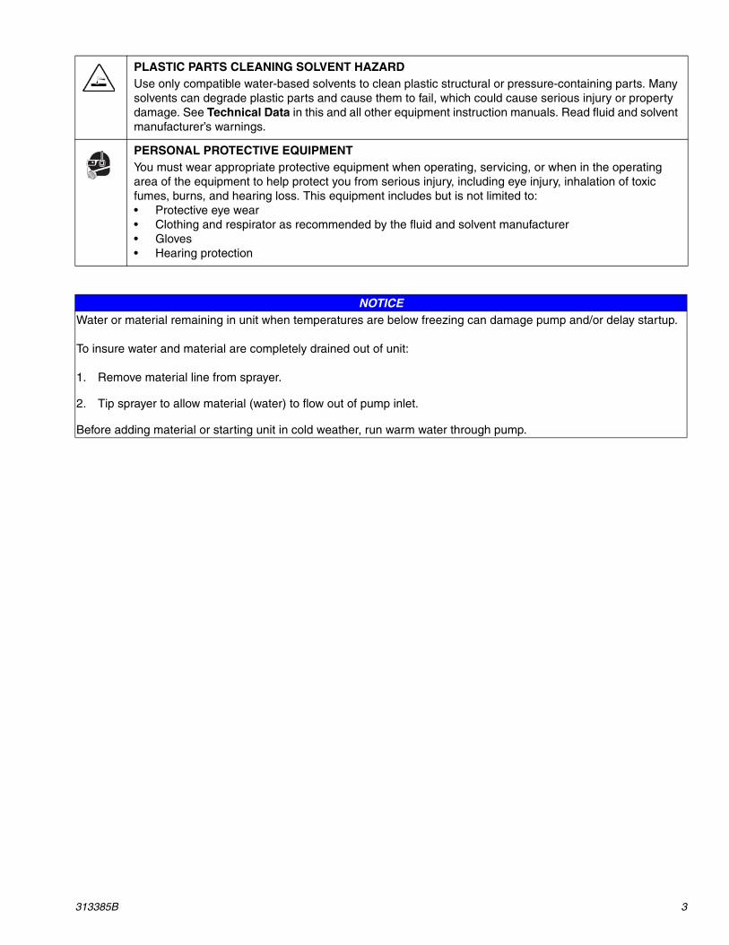
PLASTIC PARTS CLEANING SOLVENT HAZARD Use only compatible water-based solvents to clean plastic structural or pressure-containing parts. Many solvents can degrade plastic parts and cause them to fail, which could cause serious injury or property damage. See Technical Data in this and all other equipment instruction manuals. Read fluid and solvent manufacturer’s warnings.
PERSONAL PROTECTIVE EQUIPMENT You must wear appropriate protective equipment when operating, servicing, or when in the operating area of the equipment to help protect you from serious injury, including eye injury, inhalation of toxic fumes, burns, and hearing loss. This equipment includes but is not limited to:• Protective eye wear • Clothing and respirator as recommended by the fluid and solvent manufacturer• Gloves• Hearing protection
NOTICEWater or material remaining in unit when temperatures are below freezing can damage pump and/or delay startup.
To insure water and material are completely drained out of unit:
1. Remove material line from sprayer.
2. Tip sprayer to allow material (water) to flow out of pump inlet.
Before adding material or starting unit in cold weather, run warm water through pump.

Component Identification
4 313385B
Component Identification
ti13066a
L
A
J
H
G
B
EF
DC
K

Component Identification
313385B 5
Component Identification List
* Reference numbers used in gun illustrations coincide with reference numbers shown in gun manual 310616
A Nozzle Storage
B Hopper
C Hopper Quick Connect
D Diaphragm Pump
E Material Outlet Option 1
F Material Outlet Option 2
G Gun Air Outlet Quick Connect
H Material (Pump) Air Pressure Gauge and Control Knob
J Gun Air Pressure Gauge and Control Knob
K Gun (see manual 308878)*
L Air Compressor (not supplied by Graco)

Preparation
6 313385B
Preparation
Pressure Relief
1. Disconnect air inlet.
2. Open gun air valve (23).
3. Trigger gun, and spray material back into hopper.
Hopper Removal and InstallationThe hopper (G) can be removed from the cart for clean-ing and servicing equipment.
NOTE: Before removing hopper, allow unit to cool down and/or remove compressor power pack from cart.
Hopper Removal
1. To remove hopper (G), release the latches on each side of coupler (H).
2. Lift hopper straight up, off unit.
Install Hopper
1. To install hopper, position coupler over material out-let and slide it straight down, over the fitting, as far as it will go.
2. Secure latches by pushing each one up and firmly into locked position.
ti4000b
ti3900a
ti3900a
ti3899a

Pump Removal and Installation
313385B 7
Pump Removal and Installation
Pump Removal1. Relieve Pressure, page 6.
2. Remove hopper, page 6.
3. Disconnect air lines.
4. Disconnect exhaust tube.
5. Remove four bolts holding pump to cart.
6. Lift pump straight up off cart.
Pump Installation1. Lower pump on cart.
2. Replace four bolts holding pump to cart.
3. Reconnect exhaust tube.
4. Reconnect air lines.
5. Replace hopper, page 6.
ti3888a
ti3889a
ti3824a
ti3825c

Troubleshooting
8 313385B
TroubleshootingBefore performing any Troubleshooting procedures, follow Pressure Relief procedure on page 6.
PROBLEM CAUSE SOLUTION
No material output from pump Not enough air pressure to pump Shut off air at the gun, and increase air pressure to the pump to maximum. Turn regulator clockwise to increase.
Material too thick Thin the material. Material must be mixed thoroughly to a consistency that immediately folds back in as you draw your finger through the surface of the material.
Damaged checkballs or seats Replace checkballs or seats.
Plugged gun or nozzle Relieve Pressure, page 6. Remove gun from material hose, and cycle pump.
NOTE: A plugged gun or nozzle may cause the hose and pump to plug. If necessary, flush hose and pump with clean water before cycling material through the hose with the gun removed.
Plugged hose, or hose too small Relieve pressure, page 6. Flush hose with clean water, or try a 1-1/4 in. hose.
Pump stops pumping Stalled pump Shut down system. Relieve Pressure, page 6. Restart.
Contact an authorized Graco service center.
Pump in need of repair See texture pump instruction manual 308479.
Pulsing or surging material Triggering too fast Slowly squeeze trigger to fully open position while moving gun quickly in a circular motion.
Speed of application too slow Not enough air pressure to pump Shut off air at the gun, and increase air pressure to the pump to maximum. Turn regulator clockwise to increase.
Material too thick Material must be mixed thoroughly to a consistency that immediately folds back in as you draw your finger through the surface of the material.
Nozzle too small Increase nozzle size.
Hose plugged or too small. Relieve Pressure, page 6. Clean hose, or try a 1-1/4 in. hose.
Pump in need of repair See texture pump instruction manual 308479.

Troubleshooting
313385B 9
Pattern too fine or too much overspray Material too thin Thicken material. Material must be mixed thoroughly to a consistency that immediately folds back in as you draw your finger through the surface of the material.
Air pressure at gun too high Decrease air to gun at gun fitting and/or regulator.
Fluid delivery too low Increase nozzle size.
Increase air pressure to pump, or decrease air to gun at gun fitting and/or regulator.
Turn fluid knob out on gun. See Spray Techniques in Operation Manual 309915.
Pattern too coarse Material too thick Thin material. Material must be mixed thoroughly to a consistency that imme-diately folds back in as you draw your finger through the surface of the mate-rial.
Air pressure at gun too low Increase air to gun at gun fitting and/or regulator.
Fluid delivery too high Decrease nozzle size.
Decrease air pressure to pump, or increase air to gun at gun fitting and/or regulator.
Turn fluid knob in on gun. See Spray Techniques in Operation Manual 309915.
PROBLEM CAUSE SOLUTION

Parts Drawing
10 313385B
Parts Drawing
29
9
8
44
3
36
3343
32
58
40
2
3942
38
28
31
64
5
72
1
30
7
ti3953c

Parts Drawing
313385B 11
Parts Drawing
A
B
A
B
2218
22
17
24
151413
27
10
16
19
18 22
2615
17
26
10
2116
23
21
20
2511
65 7013
67
6612
71
ti3954c
75
76
68
69

Parts Drawing
12 313385B
Parts Drawing
35
34
45
38
41ti3955a
ti3956a

Parts Drawing
313385B 13
Parts List
Ref. Part Description Qty.1 15C878 FRAME, texture, blue 12 801504 FOOT, rubber 23 15C843 HOPPER, texture, gas 14 116478 WHEEL, pneumatic 25 101242 RING, retaining, ext. 26 111841 WASHER, plain 5/8 27 246887 PUMP, diaphragm, 1040, texture 18 15C759 COUPLING, pump 19 15D985 FITTING, adapter, swivel 110 118457 GAUGE, panel, mount 211 169970 FITTING, line air 112 15B565 VALVE, ball 113 104641 FITTING, bulkhead 214 156971 FITTING, nipple, short 115 115242 REGULATOR, air, 1/4 npt 216 115244 NUT, regulator 217 118486 FITTING, elbow, push 218 118481 FITTING, push 219 15C970 TUBE, air, pump, regulator 120 15C971 TUBE, air, regulator 121 15C969 TUBE, air, pump 122 15C968 TUBE, air 223 118458 FITTING, elbow, male 124 118482 FITTING, elbow, 45 125 118472 FITTING, tee 126 118484 FITTING, connector 227 116720 COUPLER, quick disconnect 128 287304 HOSE, texture, twin line 129 15W898 LABEL, brand, GTX2000 front 130 15W900 LABEL, brand, GTX2000 righT 131 15W899 LABEL, brand, GTX2000 left 132▲ 15C996 LABEL, warning, sprayer 133 15C844 COVER, holder, nozzle 134 118465 FITTING, elbow, nylon, hose 135 15C948 HOSE, exhaust 136 15D094 FILTER, hopper 137 110996 NUT, hex, flange head 4
38 111800 SCREW, cap, hex hd 539 100132 WASHER, flat 240 101566 NUT, lock 241 112717 WASHER 142 100004 SCREW, cap, hex hd 243 114966 KNOB, pronged 144 111831 SCREW, cap, skt, button hd 145 103473 STRAP, tie, wire 258 15D366 PAD, isolator, hopper bracket 159 248515 BALL, sponge, 30mm (5 pk) 160 15C090 GAUGE, thickness, fluid 165 106148 FILTER, air, 3/8npt 166 122544 SCREW, self tap, pnhd 267 15W881 SPACER, standoff, GTX 168 15X997 VALVE, check 1/8 120 psi 169 100176 BUSHING, hex 170 15W375 FITTING, 30 deg, 3/8 x 1/4 npt 171 15X567 BRACKET, compressorless 172 248093 GUN, spray, texture, bleeder 175 WASHER, #8, plain, flat 176 235208 FITTING, union, swivel 1
▲ Replacement Danger and Warning labels, tags, and cards are available at no cost.
Accessories:
248112 KIT, suction (allows sprayer to pump texture material directly out of large container or trash can)
1
248117 HOSE, 3/8 in. x 50 ft. with quick dis-connect (allows compressor to stay outside while sprayer is used inside. Can use up to three 50 ft. sections with minimal performance loss)
1
Ref. Part Description Qty.

Pump Parts Drawing
14 313385B
Pump Parts Drawing
*402
15
12
23
113
106
202*
103
19
11
20
22
25
104
401*
105108*
107
101
301*
202*
201
202*
102
113106
113
301*
202*
201*
11
3
2
5
8
16
106
113
16
3
4†
9†
7†6†
18†
17†
10†
17†
10†
▲110
ti12959a

Pump Parts Drawing
313385B 15
Pump Parts List
Ref. Part Description Qty.1 188838 HOUSING, center, aluminum 12 188854 COVER, air valve, aluminum 13 116344 SCREW, mach, hex flange hd;
M5 X 0.8; 12 mm (0.47 in.)9
4 188618 GASKET, molded Santoprene 15 188855 CARRIAGE, aluminum 16† 108730 O-RING, nitrile 17† 188616 BLOCK, air valve, acetal 18 188615 PLATE, air valve, sst 19† 188617 SEAL, valve plate, buna-N 110† 112181 PACKING, u-cup, nitrile 211 188612 PISTON, actuator, acetal 212 188613 BEARING, piston, acetal 215 188611 BEARING, pin, acetal 216 188610 PIN, pilot, stainless steel 217† 157628 O-RING, buna-N 218† 188614 BLOCK, pilot, acetal 119 188609 BEARING, shaft, acetal 220 116343 SCREW, grounding 122 188603 GASKET, air cover, foam 223 188839 COVER, air, aluminum 224 188608 SHAFT, diaphragm, sst 125 115643 SCREW, M8 X 1.25;
25 mm (1 in.)12
101 188840 COVER, fluid, aluminum 2
102 188841 MANIFOLD, inlet, aluminum 1103 188842 MANIFOLD, outlet, aluminum 1104 188607 PLATE, air side, aluminum 2105 188607 PLATE, fluid side, aluminum 2106 115643 SCREW, M8 X 1.25;
25 mm (1 in.)24
107 189044 BOLT, M12 X 1.75; 35 mm (1.38 in.) sst
2
108* 104319 O-RING, PTFE 2110▲ 188621 LABEL, warning 1113 121497 PLUG, 1 in. npt, cst 4201* 194211 SEAT, Geolast® 4202* 109205 O-RING, PTFE 8301* 114751 BALL, Geolast[, 1-1/4 in. 4401* 15B499 DIAPHRAGM, buna-N 2402* 112181 PACKING, u-cup, nitrile 2
† These parts are included in Air Valve Repair Kit 236273, which may be purchased separately.
* These parts are included in Pump Repair Kit D07GG7 which may be purchased separately.
▲ Replacement Danger and Warning labels, tags and cards are available at no cost.
Ref. Part Description Qty.

Technical Data
16 313385B
Technical DataMaximum air working pressure. . . . . . . . . . . . 120 psi (8.27 bar)Maximum working fluid pressure . . . . . . . . . . 120 psi (8.27 bar)
Compressor (not supplied)AIr Delivery . . . . . . . . . . . . . . . . . . . . . . . 12 cfm @ 100 psi
(340 lpm @ 6.9 bar)
Hopper capacityMaximum. . . . . . . . . . . . . . . . . . . . . . .17 gallons (64 liters)
Maximum delivery with texture material . . 4.0 gpm (15.14 lpm) at 12 CFM @ 100 psi (340 lpm @ 6.9 bar)
Maximum delivery with water . . . . . . . . . . 40.0 gpm (151.4 lpm) at 12 CFM @ 100 psi (340 lpm @ 6.9 bar)
DimensionsLength . . . . . . . . . . . . . . . . . . .38 in. (965 mm) with handleWidth . . . . . . . . . . . . . . . . . . . . . . . . . . . . . 24 in. (610 mm)Height . . . . . . . . . . . . . . . . . . . . . . . . . . . 40 in. (1016 mm)
WeightWith hoses, gun. . . . . . . . . . . . . . . . . . . . . 110 lb (49.9 kg)
Wetted parts . . . . . . . . . . . . . . . . . . . . . . . . PVC, zinc plate CS,buna-N, aluminum, brass, polyethylene
sst, UHMW, acetal
Sound . . . . . . . . . . . . . . . . . . .Reference pump manual 308479

Notes
313385B 17
Notes

All written and visual data contained in this document reflects the latest product information available at the time of publication. Graco reserves the right to make changes at any time without notice.
This manual contains English. MM 313385
Graco Headquarters: MinneapolisInternational Offices: Belgium, China, Japan, Korea
GRACO INC. P.O. BOX 1441 MINNEAPOLIS, MN 55440-1441Copyright 2008, Graco Inc. is registered to I.S. EN ISO 9001
www.graco.com12/2008
Graco WarrantyGraco warrants all equipment manufactured by Graco and bearing its name to be free from defects in material and workmanship on the date ofsale to the original purchaser for use. With the exception of any special, extended, or limited warranty published by Graco, Graco will, for a periodof twelve months from the date of sale, repair or replace any part of the equipment determined by Graco to be defective. This warranty applies onlywhen the equipment is installed, operated and maintained in accordance with Graco's written recommendations.
This warranty does not cover, and Graco shall not be liable for general wear and tear, or any malfunction, damage or wear caused by faulty instal-lation, misapplication, abrasion, corrosion, inadequate or improper maintenance, negligence, accident, tampering, or substitution of non-Gracocomponent parts. Nor shall Graco be liable for malfunction, damage or wear caused by the incompatibility of Graco equipment with structures,accessories, equipment or materials not supplied by Graco, or the improper design, manufacture, installation, operation or maintenance of struc-tures, accessories, equipment or materials not supplied by Graco.
This warranty is conditioned upon the prepaid return of the equipment claimed to be defective to an authorized Graco distributor for verification ofthe claimed defect. If the claimed defect is verified, Graco will repair or replace free of charge any defective parts. The equipment will be returnedto the original purchaser transportation prepaid. If inspection of the equipment does not disclose any defect in material or workmanship, repairs willbe made at a reasonable charge, which charges may include the costs of parts, labor, and transportation.
THIS WARRANTY IS EXCLUSIVE, AND IS IN LIEU OF ANY OTHER WARRANTIES, EXPRESS OR IMPLIED, INCLUDING BUT NOT LIMITEDTO WARRANTY OF MERCHANTABILITY OR WARRANTY OF FITNESS FOR A PARTICULAR PURPOSE.
Graco's sole obligation and buyer's sole remedy for any breach of warranty shall be as set forth above. The buyer agrees that no other remedy(including, but not limited to, incidental or consequential damages for lost profits, lost sales, injury to person or property, or any other incidental orconsequential loss) shall be available. Any action for breach of warranty must be brought within two (2) years of the date of sale.
Graco makes no warranty, and disclaims all implied warranties of merchantability and fitness for a particular purpose in connection with accesso-ries, equipment, materials or components sold but not manufactured by Graco. These items sold, but not manufactured by Graco (such as electricmotors, switches, hose, etc.), are subject to the warranty, if any, of their manufacturer. Graco will provide purchaser with reasonable assistance inmaking any claim for breach of these warranties.
In no event will Graco be liable for indirect, incidental, special or consequential damages resulting from Graco supplying equipment hereunder, orthe furnishing, performance, or use of any products or other goods sold hereto, whether due to a breach of contract, breach of warranty, the negli-gence of Graco, or otherwise.
FOR GRACO CANADA CUSTOMERSThe parties acknowledge that they have required that the present document, as well as all documents, notices and legal proceedings entered into,given or instituted pursuant hereto or relating directly or indirectly hereto, be drawn up in English. Les parties reconnaissent avoir convenu que larédaction du présente document sera en Anglais, ainsi que tous documents, avis et procédures judiciaires exécutés, donnés ou intentés à la suitede ou en rapport, directement ou indirectement, avec les procedures concernées.
ADDITIONAL WARRANTY COVERAGEGraco does provide extended warranty and wear warranty for products described in the "Graco Contractor Equipment Warranty Program".
Graco Phone NumberTO PLACE AN ORDER, contact your Graco distributor, or call this number to identify the distributor closest to you:
1-800-690-2894 Toll Free