important notice: in order to obtain -...
TRANSCRIPT

Important Notice: In order to obtainwarranty service on your EmulatorIII, the serial number sticker on theback panel must be intact, and youmust have a sales receipt or otherproof of purchase. If there is no serialnumber sticker on your Emulator III,please contact E-mu Systems at once.
Emulator IIIXReference Manual© 1992 by E-mu Systems, Inc.
FI 401 Rev. D
E-mu Systems, Inc.1600 Green Hills RoadP.O. Box 660015Scotts Valley, California 95067-0015(408) 438-1921
WARNING: READ THIS FIRST!IMPORTANT SAFETY INSTRUCTIONSUse in countries other than the U.S.A. may require the use of a different line cord orattachment plug, or both. To reduce the risk of fire or electric shock, refer servicingto qualified service personnel. To reduce risk of fire or electric shock do not exposethis product to rain or moisture.
GROUNDING INSTRUCTIONSThis product must be grounded. If it should malfunction or break down, groundingprovides a path of least resistance for electric current, reducing the risk of electricshock. This product is equipped with a cord having an equipment-groundingconductor and a grounding plug. The plug must be plugged into an appropriateoutlet properly installed and grounded in accordance with all local codes andordinances.
DANGERImproper connection of equipment grounding conductor can result in the risk ofelectric shock. Check with a qualified electrician or service personnel if you are indoubt as to whether the product is properly grounded. Do not modify the plugprovided with this product. If it will not fit the outlet, have a proper outlet installedby a qualified technician.
CAUTIONIf the 6100, EIIIxp is rack mounted, a standard 19 inch open frame rack must be used.
USER-MAINTENANCE INSTRUCTIONS1. The EIIIxp should be kept clean and dust free. Periodically wipe the unit with aclean, lint free cloth. Do not use solvents or cleaners.2. There are no user lubrication or adjustment requirements.3. Refer all other servicing to qualified service personnel.
INSTRUCTIONS PERTAINING TO A RISK OF FIRE, ELECTRICSHOCK, OR INJURY TO PERSONS
WARNING; When using electric products, basic precautions should always befollowed, including the following:1. Read all instructions before using the EIIIxp.2. To reduce the risk of injury, close supervision is necessary when the EIIIxp is usednear children.3. Do not use the EIIIxp near water — for example near a bathtub, washbowl, kitchensink, in a wet basement, on a wet bar, or near or in a swimming pool.4. The EIIIxp should be situated so that its location or position does not interfere withits proper ventilation.5. The EIIIxp should be located away from heat sources such as radiators, heatregisters, fireplaces, stoves, or ovens.6. The EIIIxp should only be connected to a power supply of the type described inthe operating instructions and as marked on the product.7. Care should be taken so that objects do not fall and liquids are not spilled into theenclosure of the EIIIxp through openings.
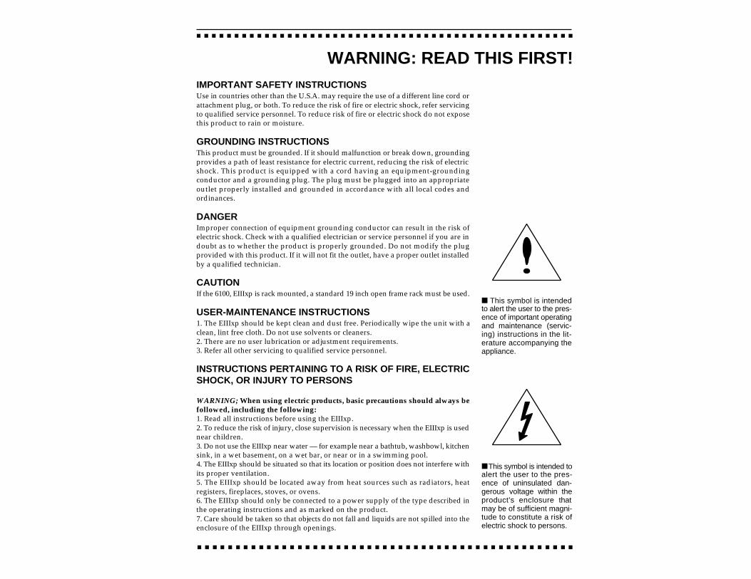
This symbol is intended toalert the user to the pres-ence of uninsulated dan-gerous voltage within theproduct's enclosure thatmay be of sufficient magni-tude to constitute a risk ofelectric shock to persons.
This symbol is intendedto alert the user to the pres-ence of important operatingand maintenance (servic-ing) instructions in the lit-erature accompanying theappliance.

8. This EIIIxp may be equipped with a polarized line plug (one blade wider that theother). This is a safety feature. If you are unable to insert this plug into the outlet, donot defeat the safety purpose of the plug. Contact an electrician to replace yourobsolete outlet.9. The power supply cord of the EIIIxp should be unplugged from the outlet whenleft unused for a long period of time.10. This product, in combination with an amplifier and headphones and speakers,may be capable of producing sound levels that could cause permanent hearing loss.Do not operate for a long period of time at a high volume level or at a level that isuncomfortable. If you experience any hearing loss or ringing in the ears, consult anaudiologist.11. The product should be serviced by qualified service personnel when:A. The power supply cord has been damaged; orB. Objects have fallen, or liquid has been spilled into the product; orC. The product has been exposed to rain; orD. The product has been dropped or the enclosure damaged; orE. The EIIIxp does not operate normally or exhibits a marked change in performance.12. All servicing should be referred to qualified service personnel.
SAVE THESE INSTRUCTIONS
RADIO and TELEVISION INTERFERENCEThe equipment described in this manual generates and uses radio-frequency energy.If it is not installed and used properly-- that is, in strict accordance with ourinstructions - it may cause interference with radio and television reception.
This equipment has been tested and complies with the limits for a Class A computingdevice in accordance with the specifications in Subpart J of Part 15 of the FCC rules.These rules are designed to provide reasonable protection against such interferencein a residential installation. However, there is no guarantee that the interference willnot occur in a particular installation, especially if a “rabbit ear” TV antenna is used.
If the EIIIxp does cause interference to radio or television reception, you can try tocorrect the interference by using one or more of the following measures: Turn the television or radio antenna until the interference stops. Move the EIIIxp to one side or the other of the television or radio. Move the EIIIxp farther away from the television or radio. Plug the EIIIxp into an outlet on a different circuit than the television or radio. Consider installing a rooftop antenna with a coaxial lead-in between the antennaand television set.

CONTENTS
1-GENERAL INSTRUCTIONSIntroduction 1-3Initial SCSI Setup 1-5Connection Instructions 1-8Sampling Basics 1-12Definitions 1-14Additional Definitions 1-18
2-CONTROLS
3-GUIDED TOURSEIIIX Modules 3-21 - Meet the EIIIxp 3-42 - Specifying the Current 3-7
Sample and Current Zone3 - Dynamic Processing 3-9
of a Zone4 - Realtime Control 3-17
Programming5 - Basic Sampling 3-206 - Digital Processing 3-247 - Managing the Bank 3-318 - On Your Own 3-32
MODULES
4-MASTER/GLOBALS1. Master Tune 4-22. Rename Bank 4-33. Erase Bank 4-44. Dynamic Allocation 4-55. Save as EIII Bank 4-66. Memory Available 4-77. Disk Utilities 4-88. Special 4-219. MIDI 4-300. Import Options 4-37
5-SAMPLE MANAGEMENT0. Select Sample 5-21. Load Sample 5-32. Rename Sample 5-53. Erase Sample 5-64. Copy Sample 5-75. Setup 5-86. Place Sample 5-107. Arm Sampling 5-128. Force Sampling 5-139. MIDI Sample Dump 5-14
6-PRESET MANAGEMENT1. Load Preset 6-22. Rename Preset 6-43. Erase Preset 6-54. Copy Preset 6-65. Create Preset 6-76. Preset Size 6-87. Stack Mode 6-98. Velocity Switch Level 6-109. Merge Presets 6-11
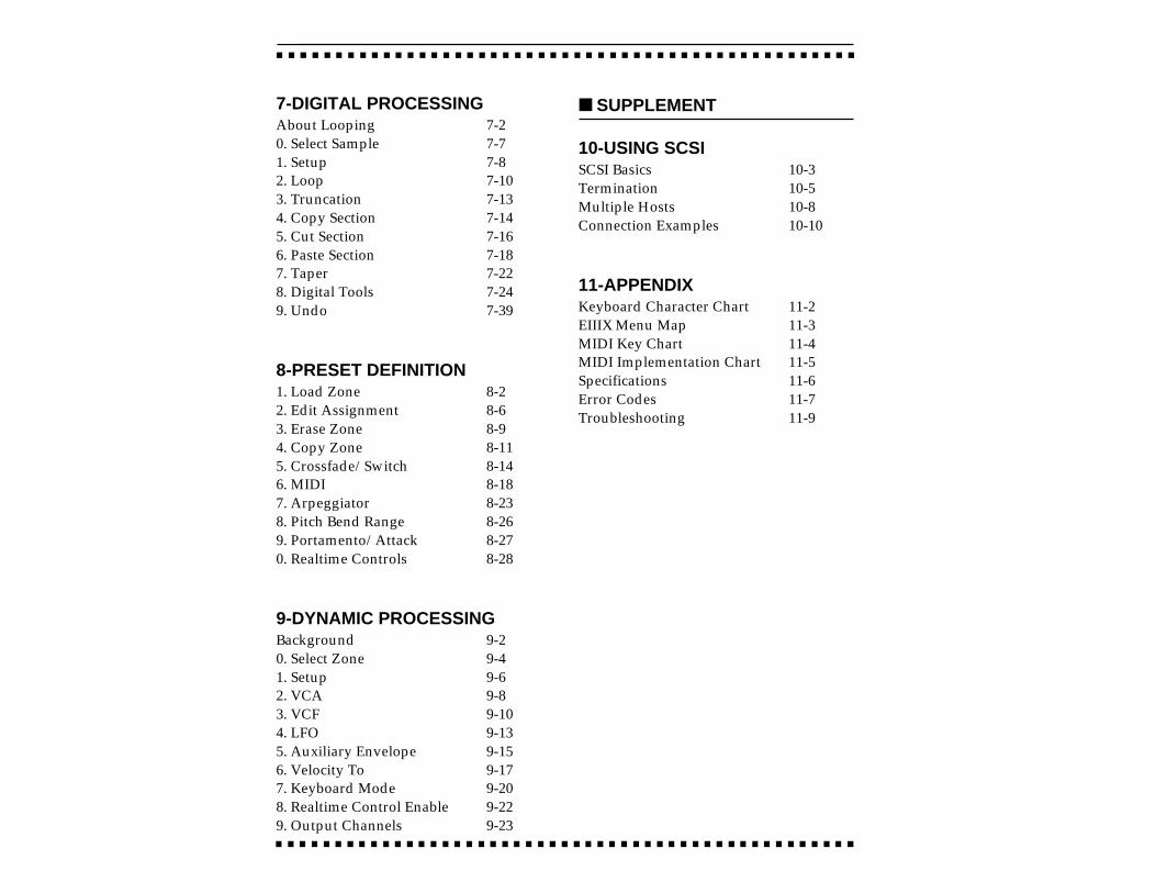
7-DIGITAL PROCESSINGAbout Looping 7-20. Select Sample 7-71. Setup 7-82. Loop 7-103. Truncation 7-134. Copy Section 7-145. Cut Section 7-166. Paste Section 7-187. Taper 7-228. Digital Tools 7-249. Undo 7-39
8-PRESET DEFINITION1. Load Zone 8-22. Edit Assignment 8-63. Erase Zone 8-94. Copy Zone 8-115. Crossfade/Switch 8-146. MIDI 8-187. Arpeggiator 8-238. Pitch Bend Range 8-269. Portamento/Attack 8-270. Realtime Controls 8-28
9-DYNAMIC PROCESSINGBackground 9-20. Select Zone 9-41. Setup 9-62. VCA 9-83. VCF 9-104. LFO 9-135. Auxiliary Envelope 9-156. Velocity To 9-177. Keyboard Mode 9-208. Realtime Control Enable 9-229. Output Channels 9-23
SUPPLEMENT
10-USING SCSISCSI Basics 10-3Termination 10-5Multiple Hosts 10-8Connection Examples 10-10
11-APPENDIXKeyboard Character Chart 11-2EIIIX Menu Map 11-3MIDI Key Chart 11-4MIDI Implementation Chart 11-5Specifications 11-6Error Codes 11-7Troubleshooting 11-9


1-GENERAL INSTRUCTIONS
INTRODUCTION 1-3
INITIAL SCSI SETUP 1-5
CONNECTION 1-8INSTRUCTIONS
SAMPLING BASICS 1-12
DEFINITIONS 1-14
ADDITIONAL 1-18DEFINITIONS

INTRODUCTION
This is the reference manual for the Emulator Three X Digital SoundProduction System. It contains detailed information on all aspectsof the EIIIX's operation.
If you are totally unfamiliar with samplers and synthesizers ingeneral, you may need more information than this manual pro-vides. We suggest that you read some of the many books andmagazines on the subject of music synthesis in order to learn thebasics while you are learning about the Emulator IIIX. This will helpyou to get the most out of this extremely powerful instrument.
The functions of the Emulator IIIX are detailed in this manual bytheir module. Screen displays and step-by-step instructions aredescribed for all aspects of use and operation. Sidebars are usedto highlight important points or to give useful operational tipswhich might not be readily apparent.
We encourage you to take a moment now to read the E-mu Systemswarranty and to fill out and send in your warranty registration card.By doing so, you are assured of receiving news of all updates andmanual revisions.

What's an EIIIX?The EIIIX is the latest in the long line of E-mu sampling products,beginning with the Emulator I and evolving into the EII and EIII. Indeveloping the EIIIX, we have retained the logical and easy-to-useuser interface of the EIII and enhanced it with our all-digital, state-of-the-art G-chip and H-chip hardware. The G-chip allows noise-free sample transposition over a ±5 octave range. The H-chips retainthe warm character of analog filters while keeping the signalentirely in the digital domain.
The EIIIX can be used as an EIII expander unit or as a stand-alonesample playback system. In addition, the EIIIX is fully compatiblewith the original EIII and has full access to the huge library ofsounds available from E-mu and other sources.
Some of the major enhancements from the original EIII are asfollows:
32 megabytes of sample RAM (non-proprietary, user installable) 32 audio channels (16 stereo) 8 polyphonic, balanced audio outputs Up to 999 samples per bank Up to 256 presets per bank All digital signal path for lower noise and improved reliability Digital I/O (S/PDIF, AES/EBU) Improved user interface simplifies multi-timbral operation
One difference from the original EIII is in the deliberate omission ofanalog sample inputs. We have discovered that most people do notsample their own sounds and we feel that you should not have topay for a expensive feature that you may not use. Furthermore, thewidespread use of portable DAT recorders incorporating digital I/O makes built-in A/D converters redundant. Any audio gearincorporating an A/D converter and digital I/O can function as asampling “front end” for the EIIIX.
You should plan on purchasing a mass storage device for use withthe EIIIX, if you don't already own one. When dealing with largebanks of up to 32 MB, a floppy disk drive simply doesn't cut it evenfor back-up. An optical or hard disk is an absolute must!
The EIIIX is an extremely powerful and reliable, fourth generationinstrument. We at E-mu Systems sincerely hope it will help yourealize and further your musical dreams.
INITIAL SCSI SETUP
In order to move sounds in and out of the EIIIX you need a massstorage device such as a hard disk or optical disk. The EIIIX can loadand save sounds using the floppy disk drive, but this is really aterrible waste of your time. Plan on getting a mass storage device assoon as possible. If your EIIIX has a built-in hard disk drive, you canskip this section and go directly to the connection instructions. Thisinitial setup section contains step-by-step instructions on how toconnect the EIIIX to the following SCSI setups:
Connecting the EIIIX to a pre-formatted and loaded hard disk.
Connecting the EIIIX to an un-formatted hard (or optical) disk.
Connecting EIIIX to a Pre-formatted Hard Disk(Your EIIIX dealer has pre-formatted a hard disk drive for you and loaded
it with sounds.)
1. Position the SCSI device and the EIIIX in a stable location.Hard disk drives are particularly susceptible to shock and vibra-tion. Make sure that you position your hard disk where it won't bebumped or moved while in use.
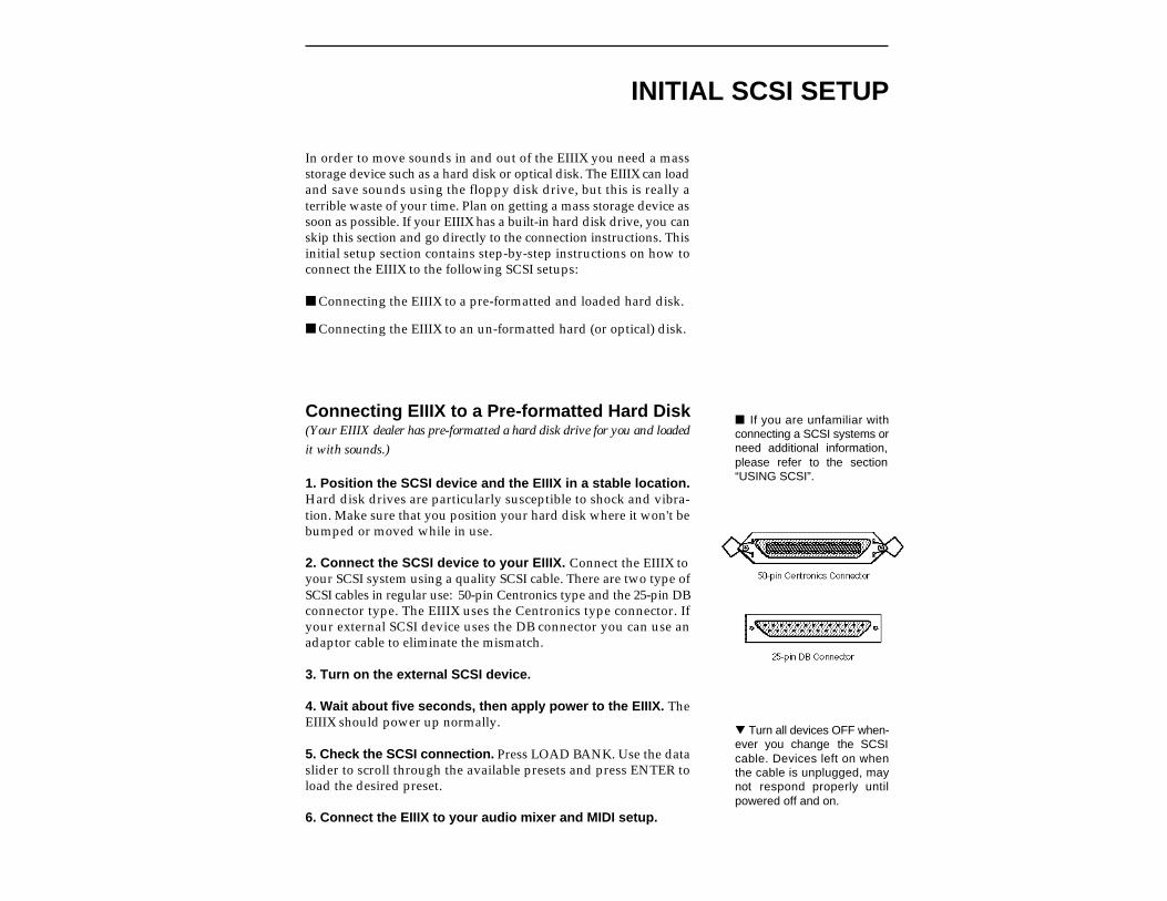
2. Connect the SCSI device to your EIIIX. Connect the EIIIX toyour SCSI system using a quality SCSI cable. There are two type ofSCSI cables in regular use: 50-pin Centronics type and the 25-pin DBconnector type. The EIIIX uses the Centronics type connector. Ifyour external SCSI device uses the DB connector you can use anadaptor cable to eliminate the mismatch.
3. Turn on the external SCSI device.
4. Wait about five seconds, then apply power to the EIIIX. TheEIIIX should power up normally.
5. Check the SCSI connection. Press LOAD BANK. Use the dataslider to scroll through the available presets and press ENTER toload the desired preset.
6. Connect the EIIIX to your audio mixer and MIDI setup.
If you are unfamiliar withconnecting a SCSI systems orneed additional information,please refer to the section“USING SCSI”.
Turn all devices OFF when-ever you change the SCSIcable. Devices left on whenthe cable is unplugged, maynot respond properly untilpowered off and on.

Connecting EIIIX to an Unformatted Hard Disk
1. Position the SCSI device and the EIIIX in a stable location.Hard disk drives are particularly susceptible to shock and vibra-tion. Make sure that you position your hard disk where it won't bebumped or moved while in use.
2. Connect the SCSI device to your EIIIX. Connect the EIIIX toyour SCSI system using a quality SCSI cable. There are two type ofSCSI cables in regular use, 50-pin Centronics type and the 25-pin DBconnector type. The EIIIX uses the Centronics type connector. Ifyour external SCSI device uses the DB connector you can use anadaptor cable to eliminate the mismatch.
3. Set the SCSI ID of your external SCSI device to any numberother then 5. (5 is the default ID of the EIIIX). Consult the operationmanual of your SCSI device for this procedure.
4. Turn on the external SCSI device.
5. Insert the software floppy disk supplied with your EIIIX into thefloppy disk drive. Insert the disk, metal end first with the label sideup.
6. Apply power to the EIIIX. The EIIIX should power up normally.It will wait a few seconds, then begin loading the floppy disksoftware. Remove the floppy disk when the EIII has finished load-ing and put it aside in a safe place.
7. Make sure your hard disk really is unformatted. Formatting ahard disk erases all the data on it. Press the Load button. If thedisplay reads, “No Valid Drives” the drive isn't formatted. Con-tinue on to step eight.
8. Format the hard disk. Press the Master/Global button, then 77on the numeric keypad. The display should read, “FORMATDISK”. Use the data slider to select your hard disk, then pressENTER. The display asks, “Are You Sure?” Press the Inc/Yesbutton to confirm. Formatting takes a few minutes. Time to take abreak.
9. Copy the floppy disk software onto the hard disk. Use theCopy Software function (Master/Globals, 7, 4). The display shows:
COPY SOFTWARE fromD0 Floppy Drive
Select a Drive
Turn all devices OFF when-ever you change the SCSIcable. Devices left on whenthe cable is unplugged, maynot respond properly untilpowered off and on.
Always use 50-pinCentronics-type cables withthe EIIIX. These cableshave much better electricalcharacteristics and havefewer problems.
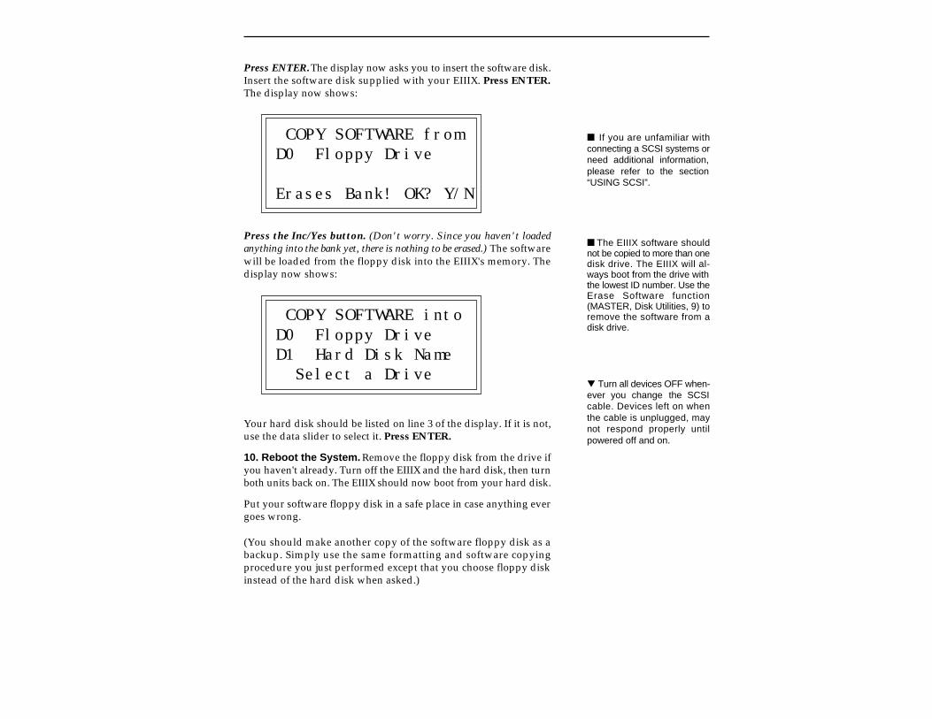
Press ENTER. The display now asks you to insert the software disk.Insert the software disk supplied with your EIIIX. Press ENTER.The display now shows:
COPY SOFTWARE fromD0 Floppy Drive
Erases Bank! OK? Y/N
Press the Inc/Yes button. (Don't worry. Since you haven't loadedanything into the bank yet, there is nothing to be erased.) The softwarewill be loaded from the floppy disk into the EIIIX's memory. Thedisplay now shows:
COPY SOFTWARE intoD0 Floppy DriveD1 Hard Disk Name Select a Drive
Your hard disk should be listed on line 3 of the display. If it is not,use the data slider to select it. Press ENTER.
10. Reboot the System. Remove the floppy disk from the drive ifyou haven't already. Turn off the EIIIX and the hard disk, then turnboth units back on. The EIIIX should now boot from your hard disk.
Put your software floppy disk in a safe place in case anything evergoes wrong.
(You should make another copy of the software floppy disk as abackup. Simply use the same formatting and software copyingprocedure you just performed except that you choose floppy diskinstead of the hard disk when asked.)
If you are unfamiliar withconnecting a SCSI systems orneed additional information,please refer to the section“USING SCSI”.
The EIIIX software shouldnot be copied to more than onedisk drive. The EIIIX will al-ways boot from the drive withthe lowest ID number. Use theErase Software function(MASTER, Disk Utilities, 9) toremove the software from adisk drive.
Turn all devices OFF when-ever you change the SCSIcable. Devices left on whenthe cable is unplugged, maynot respond properly untilpowered off and on.
CONNECTION INSTRUCTIONS
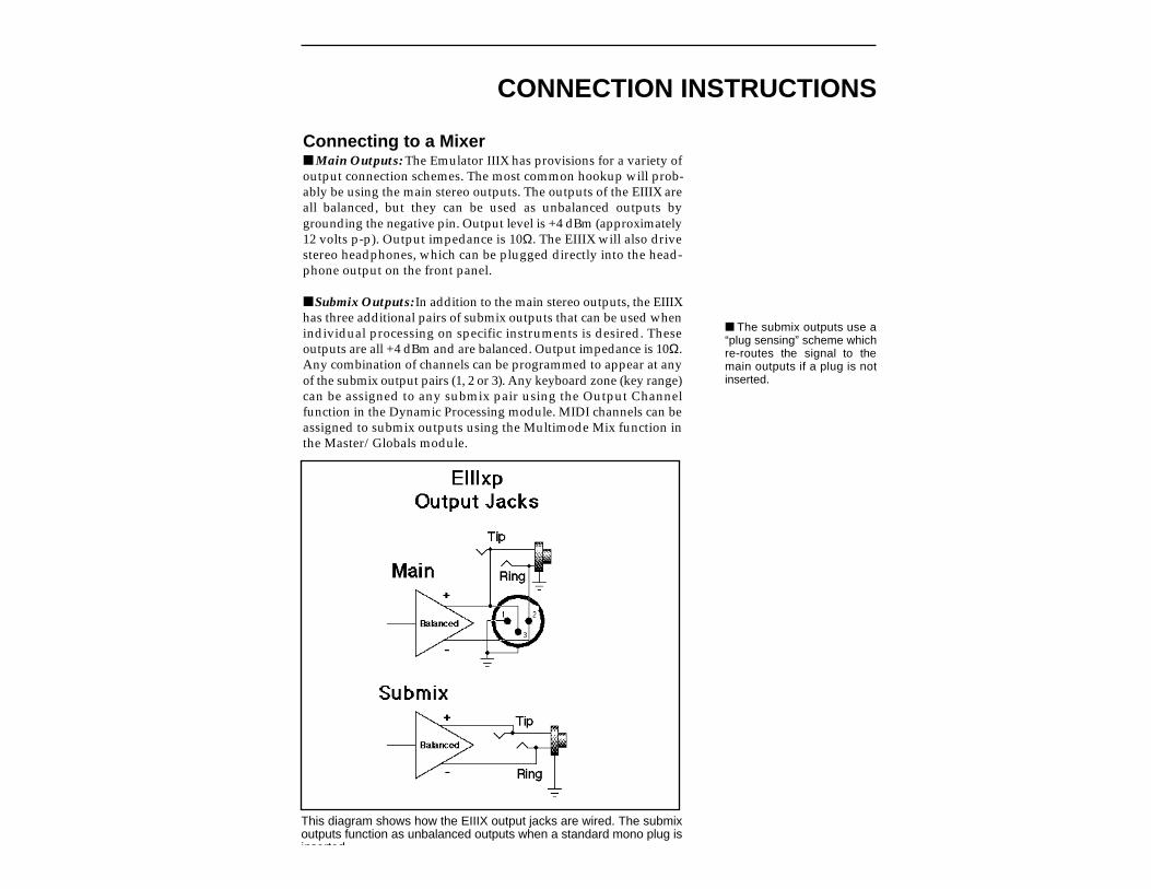
Connecting to a Mixer Main Outputs: The Emulator IIIX has provisions for a variety ofoutput connection schemes. The most common hookup will prob-ably be using the main stereo outputs. The outputs of the EIIIX areall balanced, but they can be used as unbalanced outputs bygrounding the negative pin. Output level is +4 dBm (approximately12 volts p-p). Output impedance is 10Ω. The EIIIX will also drivestereo headphones, which can be plugged directly into the head-phone output on the front panel.
Submix Outputs: In addition to the main stereo outputs, the EIIIXhas three additional pairs of submix outputs that can be used whenindividual processing on specific instruments is desired. Theseoutputs are all +4 dBm and are balanced. Output impedance is 10Ω.Any combination of channels can be programmed to appear at anyof the submix output pairs (1, 2 or 3). Any keyboard zone (key range)can be assigned to any submix pair using the Output Channelfunction in the Dynamic Processing module. MIDI channels can beassigned to submix outputs using the Multimode Mix function inthe Master/Globals module.
This diagram shows how the EIIIX output jacks are wired. The submixoutputs function as unbalanced outputs when a standard mono plug isinserted.
The submix outputs use a“plug sensing” scheme whichre-routes the signal to themain outputs if a plug is notinserted.
Stereo Headphone OutputThe headphone output is located on the left side of the front paneland is capable of driving all types of stereo headphones. The outputlevel is controlled by the master volume slider.
MIDI ConnectionThe Emulator IIIX provides a MIDI IN, a MIDI OUT and a MIDITHRU port.
The MIDI IN port on the EIIIX connects to the MIDI OUT port ofan external MIDI controller which could be a keyboard, a sequencer,MIDI drum kit or whatever. Note that the EIIIX can only respond toinformation that your controller transmits. If your MIDI keyboarddoes not have velocity and pressure sensitivity, the EIIIX will notrespond to velocity and pressure.
MIDI OUT can be connected to another MIDI instrument orcomputer. The MIDI OUT jack is used to transmit preset changeinformation, MIDI sample dump information (transfers sampledata) or for MIDI Overflow mode, which allows a second EIIIX to beconnected to the MIDI OUT to double the number of channels. SeePreset Definition, 6, MIDI for more details.
MIDI THRU simply re-transmits any information received at theMIDI IN port. Use cords that have been designed specifically forMIDI. While regular 5 pin DIN cords may work, they are notshielded correctly for MIDI use and may cause ground loopsbetween equipment.
Digital I/OThe digital input and output jacks allow you to transfer audio backand forth with other digital devices equipped with either AES/EBUor S/PDIF digital I/O. The digital input allows you to sampledirectly from a DAT recorder or other digital device. The digitaloutput reflects the data at the main outputs of the EIIIX. See theSample Management module and Main output Format (locatedunder Special in the Master/Globals menu) for more information.
SCSIThe SCSI connectors are high-speed parallel interfaces which arenormally used to interface the EIIIX with external mass storagedevices such as hard disks or magneto-optical discs. A SCSI port canalso be used to link the EIIIX with an external computer for ex-tremely fast file transfers.
For more information on SCSI installation, see the section, “UsingSCSI”. You may also want to refer to the operation manual thataccompanies your external SCSI device.
110V / 220V OperationThe Emulator IIIX may be used in either 110 volt or 220 voltenvironments at either 50 Hz or 60 Hz. No change of voltage settingsis required. The EIIIX automatically switches itself for 100 or 220Volt operation.
AC Power Connection and FuseThe AC power connector is where the Emulator IIIX gets its power.The fuse receptacle is located directly over the power receptacle.Before changing or checking a fuse, UNPLUG the power cord. Toremove the fuse holder, squeeze the two tabs located on either sideof the fuse holder together. The fuse holder will now pop out withits two fuses. The Emulator IIIX uses two 2-amp, 250 volt fast-blomini-fuses. The EIIIX should not normally blow fuses. If a fuse thathas been replaced blows again, do not attempt another replace-ment. Have the unit serviced!

SAMPLING BASICS
DIGITAL SAMPLING. The signal level is repeatedly measured at a high rate and the measurements storedin digital memory. On playback, the measurements are converted back into voltages to reconstruct theoriginal waveform.
Throughout this manual we will use the terms and concepts de-scribed and defined below. Read through this section carefully,even if you don’t retain it all. You can refer back periodically as youread through the manual until you understand the basics anddefinitions.
The Emulator IIIX is conceptually like a tape recorder. However, therecording process is very different since the EIIIX digitally recordsinto its computer memory. Sounds for the EIIIX can be loaded viaremovable-media hard disk, magneto-optical disk, CD-ROM usingthe SCSI interface; or through the AES/EBU Digital interface; orthrough MIDI using MIDI Sample Dump.

Computers can accept information only in the form of numbers, sofirst the EIIIX accepts audio signals coded into binary numbers.Samplers work by examining (sampling) the incoming signal levelat a very high rate (44,100 times a second for compact discs), andsequentially records these different levels in memory. Once stored,these samples may be played back (in the proper sequence, ofcourse) to reconstruct the original signal. For instance, if a two-second sound was being sampled at 44.1 kHz, it would require (2 X44,100) or 88,200 samples to be recorded. As you might imagine,shorter sounds require fewer samples.
A sound can be manipulated once it has been recorded. Playingback the samples in reverse order from which they were storedplays the sound backwards. Playing back the samples at a faster ratethan the rate at which they were stored raises the pitch. Playing backat a slower rate lowers the pitch, much like a tape recorder’s variablespeed control.
How the Emulator IIIX Organizes SoundsSure, you’re anxious to start coaxing wonderful sounds from theinstrument—but the following is a necessary part of learning howto play the Emulator IIIX. It is important to understand how theEIIIX organizes sounds in order to make best use of the instrumentin the shortest possible time. Many terms will be introduced nowthat show up later in the manual.
You can think of the EIIIX as resembling a collection of sound-organizing modules, all contained within an EIIIX bank. Pathwaysindicate how information flows within the EIIIX. Let’s take a closerlook at what makes up this information, and how it is transferredfrom one section of the instrument to another. We’ll start withindividual samples, then work our way through the system.
The SampleLoading in any sound in mono or stereo creates a sample, the rawmaterial with which the EIIIX works. The total available samplingtime can be divided up any way you like—one long sample, lots ofshort samples, a few medium samples, or any combination thereof.
The term sample commonly means two different things:1) A digital recording of a complete sound, or2) each snapshot of the sound that makes up the complete sample.Confusing? You bet! In this manual, we’ll assume sample means thecomplete recorded sound unless indicated otherwise.

You can modify a raw sample in several ways:
Transposition: A sample can be transposed up or down in pitchto cover a particular range of the keyboard. By doing this, it is notnecessary to record a sample for every key.
Digital Processing: Digital processing consists of Looping asample (allowing even short samples to play indefinitely).
Dynamic Processing: Just as synthesizers include signal proces-sors (filter, voltage-controlled amplifier, envelope generators, LFO,and so on) to modify the sounds produced by the synth’s oscillators,the Emulator IIIX includes similar modules for modifying rawsamples or combinations of samples.
The PresetAs mentioned above, a sample can be assigned to a single note onthe keyboard, or transposed polyphonically to cover a wider key-board range. A preset is one entire keyboard setup. The process ofassigning, and optionally transposing, samples to specific ranges ofthe keyboard is called making a preset. Making a preset is a three-step process:
1. Create the preset and give it a number and name. The bank canhold up to 256 Presets (000-255).
2. Place samples to different keyboard ranges. For example,with five samples you could assign each sample to cover one octaveof the keyboard. A sample can be assigned more than once withina given preset, and assigned to more than one preset.
3. Choose from a number of the available options that furtherdefine the preset. Some examples are: assigning samples to par-tially or fully overlap other samples, thus producing doublingeffects, or assigning dynamic control to individual samples in apreset. You can modify zone parameters, add arpeggiation, and setup MIDI and dynamic processing parameters.
Since wide-range transposi-tion alters the sample’s timbre,it is often necessary to usemultiple samples and trans-pose each one over a smallrange to give the most realisticsound. This is particularly truewith acoustic instruments.
DEFINITIONS
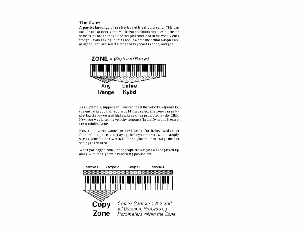
The ZoneA particular range of the keyboard is called a zone. This caninclude one or more samples. The zone’s boundaries need not be thesame as the boundaries of the samples contained in the zone. Zonesfree you from having to think about where the actual samples areassigned. You just select a range of keyboard (a zone) and go!
As an example, suppose you wanted to set the velocity response forthe entire keyboard. You would first select the zone range byplaying the lowest and highest keys when prompted by the EIIIX.Next you would set the velocity response (in the Dynamic Process-ing module). Done.
Now, suppose you wanted just the lower half of the keyboard to panfrom left to right as you play up the keyboard. You would simplyselect a zone for the lower half of the keyboard, then change the pansettings as desired.
When you copy a zone, the appropriate samples will be picked upalong with the Dynamic Processing parameters.
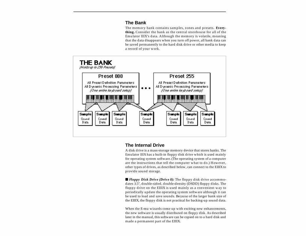
The BankThe memory bank contains samples, zones and presets. Every-thing. Consider the bank as the central storehouse for all of theEmulator IIIX’s data. Although the memory is volatile, meaningthat the data disappears when you turn off power, all bank data canbe saved permanently to the hard disk drive or other media to keepa record of your work.
The Internal DriveA disk drive is a mass-storage memory device that stores banks. TheEmulator IIIX has a built-in floppy disk drive which is used mainlyfor operating system software. (The operating system of a computerare the instructions that tell the computer what to do.) However,other types of drives, as described below, can connect to the EIIIX toprovide sound storage.
Floppy Disk Drive (Drive 0): The floppy disk drive accommo-dates 3.5", double-sided, double-density (DSDD) floppy disks. Thefloppy drive on the EIIIX is used mainly as a convenient way toperiodically update the operating system software although it canbe used to load and save sounds. Because of the larger bank size ofthe EIIIX, the floppy disk is not practical for backing-up sound data.
When the E-mu wizards come up with exciting new enhancements,the new software is usually distributed on floppy disk. As describedlater in the manual, this software can be copied on to a hard disk andmade a permanent part of the EIIIX.

External DrivesThe EIIIX includes a SCSI (Small Computer Systems Interface)connector on the rear panel. This interface is commonly used in thecomputer industry, so many devices made to work with comput-ers—particularly mass storage devices—will also work with theEIIIX. Here are some of the types of mass storage devices that canplug into the EIIIX’s SCSI connector.
Hard Disk Drive: A hard disk provides the advantages of muchhigher memory capacity and far faster access time. Transferringdata to and from the EIIIX is quite straightforward. However, youcannot remove a hard disk and replace it with another one—the diskis a permanent part of the drive. There are three main cautionsinvolved with hard disks:
Hard disks are sensitive to extreme mechanical shocks. Ifyour hard disk falls off a keyboard stand, chances are thehard disk will be damaged.
Make sure power is not interrupted when you write data tothe hard disk.
Hard disks have reached a very high level of reliability.However, they can fail from time to time (as can any part ofa computer), so any data should be backed up periodicallyand regularly on some other medium.
Removable-media Hard Disk Drives: These are similar to normalhard disk drives except that the disk itself can be removed andreplaced with another disk. Disk densities can range from 44Mbytes to well over 100 Mbytes per platter. Removable-media harddisk drives allow you to build a sound library of unlimited size andare quite handy for transferring sounds between machines.
CD-ROM Drive: A CD-ROM is a playback-only (data cannot bewritten to it) mass storage memory device whose capacity is ap-proximately 660 Megabytes. Quality CD-ROM libraries are avail-able from several companies. (Northstar, Optical Media Interna-tional, E-mu Systems, Inc.) These can be loaded into the bank aseasily as you would load from a hard disk.
Magneto-Optical Drive: Basically a read/writable CD, thesehigh speed, high density storage devices are currently the hottestthing around for storing large amounts of sound data. Typically amagneto-optical drive can upwards of 300 Mb per side and theremovable cartridges can be used over and over. Disk access time iscomparable to a normal hard disk, and is sometimes even faster!Advantages: High-speed, high-density, reliable, removable.Disadvantage: High cost (although prices are dropping fast).

ADDITIONAL DEFINITIONS
If a module is already active,and you are finished with onesubmodule, you do not need tore-activate the module—justkey in the new submodulenumber.
The Primary and Secondary SampleAn Emulator IIIX key provides for two channels. These contain theprimary and secondary samples. For example, the primary samplemight be a guitar note and the secondary sample a detuned versionof the same guitar note. When played together, you hear chorusing.Also, a preset contains information about how the keyboard dy-namics affect the primary and secondary samples. As an example,the primary sample could be that of a drum hit played softly, and thesecondary of a drum hit played loudly. Thus, playing the keyboardsoftly would play the primary sample, and playing the keyboardmore forcefully would play the secondary sample.
The Current PresetWhen you load a bank, a preset will be ready to play and the displaywill show the preset number. This is the current preset. If you selectanother preset, or create a preset, that will become the currentpreset.
The Current SampleWhen loading an individual sample, you will need to specify thesample number and name into which the sound should be recorded.This is called the current sample.
ModulesA module controls a particular set of functions in the Emulator IIIX.There are six main modules : Master/Globals, Preset Management,Preset Definition, Sample Management, Digital Processing, andDynamic Processing.
Activating a Module and the Module Identifier: To work with amodule, you must first activate it. Press the button associated withthe desired module. The display will then show the Module Iden-tifier and invite you to select a submodule.
Submodule: Each module contains several numberedsubmodules that set controls for additional functions. There are twoways to select a submodule within the module. You can move thedata slider until the display shows the desired submodule, thenpress ENTER. As you work with the EIIIX, though, you will start tomemorize the submodule numbers and will probably find it fasterto simply key in the appropriate submodule number using thenumeric keypad. When using the keypad, it is not necessary to pressENTER. Pressing either the module button or the Escape buttonwill cancel the operation.
SavingThe bank only retains data for as long as the Emulator IIIX isplugged in and turned on. Of course, we don’t expect you to leavethe thing on all the time, which brings us to the subject of savingdata.
Pressing the SAVE button on the Control Panel shuttles all the bankdata (samples and presets) to the drive of your choice . A hard diskpermanently stores data so that even after turning off the EmulatorIIIX, the disk will contain a record of your work.
IF YOU DO NOT SAVE A BANK, ALL BANK DATA WILLBE LOST WHEN YOU TURN OFF THE MACHINE.
Do not wait until the end of a session to save. Save your workperiodically in case of power failure or some other unforeseencircumstance that might erase the bank’s memory. Hard disks arenot infallible. All hard disk banks should be backed up periodicallyto another hard disk or other media. Should you improve the preset,sample, or sequence later, you can always replace the original withthe revised version. And if something goes wrong, the original willstill be available to save you the ordeal of starting from scratch.Whenever you have done enough work that you would hate tolose it, back it up!
Since the disk contains a record of the bank data, loading the diskback into the bank transfers all the sample and preset data into thebank. This will replace the existing bank data, if any.
BootingBooting is a computer term that means “having the computer readthe software necessary for its operation from the disk.” (It’s easy tosee why this was shortened to booting.) The EIIIX automaticallyboots itself from a hard disk when you turn it on. Once booted, theinstrument is ready to go. If the hard disk is damaged for somereason, the EIIIX can be booted from a suitable floppy disk.
DefaultA default setting is what we’ve judged to be a useful initial setting,and remains in effect until you change it. For example, if you createa new preset, the arpeggiator will default to Off. Had it defaulted tothe on position, all new presets would be arpeggiated.
If you want to maintaincompatability with the originalEIII, use function Master, 5“Save as EIII Bank”. This willallow the EIII to load your EIIIXbank.
The CursorThe cursor is that small flashing line on the display. It sits under thenumber or letter that will be altered if you enter data. Entering a newvalue will overwrite the number or letter above the cursor, where-upon the cursor will move on to the next number or letter (ifapplicable). If the EIIIX is expecting a two or three-digit number, inmost cases you must enter all the required digits even if some ofthese are zeroes (called leading zeroes). For example, if the EIIIX isexpecting a three-digit number and you want to enter 8, you wouldenter 008. If it is expecting a single-digit number, entering 8 wouldbe sufficient.
Data Slider & Increment/Decrement ButtonsIn virtually all instances where the data slider selects options, theIncrement (Inc/Yes) and Decrement (Dec/No) switches duplicatethe slider. Press Inc/Yes to increase a value, or Dec/No to decrease.
SelectingWhen the instructions say to select an option, you can use whatevermethod is most comfortable for you: the data slider, the Increment/Decrement buttons, the numeric keypad (if applicable) and, whennaming, the keyboard keys. Some functions do not implement allthese options; you can’t go wrong by trying, though. If a functiondoesn’t respond to the numeric keypad, for instance, then pressingthe keypad will have no effect. Use the data slider or the Inc/Decbuttons instead.
The Big Re-Cap
A sample is a raw sound that is loaded into the bank.
To create a new preset, make sure you have all the samplesrequired for the preset in the bank, number and name a preset, thenassign combinations of samples from the bank to specific sections ofthe keyboard. By specifying one or more of these samples (orportions thereof) as a zone, the zone may then be processed by theEIIIX’s dynamic signal processors.
After arranging a bank, it can be saved to one or more drives.
Since loading from a hard disk fills the bank with samples andpresets, you can group these samples into new presets, process thesamples contained in particular zones, or alter existing presets.


2-CONTROLS
MASTER VOLUME 2-2
DATA SLIDER 2-2
INC/DEC BUTTONS 2-2
TEN KEY PAD 2-2
ESCAPE 2-3
ENTER 2-3
AUDITION 2-4
CURSOR/PAGE 2-3
PRESET SELECTION 2-4
SAVE BANK 2-5
LOAD BANK 2-6
DRIVE SELECT 2-7
MULTIMODE 2-8
TRANSPOSE 2-9
MASTER VOLUMEThe Master Volume Slider controls the volume of every audiooutput on the EIIIX including the submix and headphone outputs.The master volume slider is a digital control. For maximum dy-namic range it should be kept near the maximum position.
TEN KEY PAD
DATA SLIDERUsing the Data Slider is the most common way to change parametervalues on the EIIIX. Moving the slider changes either the data overthe flashing cursor or scrolls through options in the display.
INCREMENT/DECREMENT BUTTONSOn all EIIIX menus where the data slider selects options, theIncrement (Inc/Yes) and Decrement (Dec/No) Buttons duplicatethe slider function. The increment/decrement should be used whena finer degree of control is required. They can also be used forselecting Yes or No.
The Ten Key Pad is used to enter data in precise amounts. Forinstance, if you wanted to jump to preset 10, enter 10 on the ten keypad and the new preset number will be instantly selected, eliminat-ing the process of finding the number with the data slider and thenpressing ENTER.
ESCAPEThe Escape button lets you back out of the module by one menueach time the button is pressed. It can also be used anytime you donot want to execute a particular function (bail out). In the SampleManagement module, pressing the Escape button terminates thesampling process.
ENTERA flashing ENTER LED means that the EIIIX wants you to dosomething, indicating either that data needs to be entered, or thatpressing the ENTER button will activate an operation. If the EN-TER LED is lit steadily, pressing ENTER is optional. Doing so willexit you from the function and return you to the Module Identifier.You also have the option of going directly to another functionwithin the module.
AUDITIONThe Audition Button allows you to play notes on the EIIIX directlyfrom the front panel without a MIDI keyboard being connected. Thenote that will be played is selected from the Audition Key function,located under Special in the Master/Globals module.
CURSOR/PAGEThe Cursor is a small flashing line that appears in the displaywindow under the data that is currently being edited. The Cursor/Page Buttons are used to move the cursor around in the display. Thebuttons are marked with arrows to indicate the direction of move-ment. Some of the functions on the Emulator IIIX have more optionsthan will fit on a single page of the display. In this case the < and >arrows become the Page selects, allowing you to move through thevarious pages of the display.
PRESETSELECTION
CURSOR/PAGE
The Cursor/Page keys perform the following functions:
1.Moving the cursor. To move the flashing cursor line in a particu-lar direction in order to select a different function, simply press thecorresponding cursor key.
2.Selecting the display page. In many submodules, a singlescreen of the LCD cannot display all the available parameters.Arrows (<- ->) in the display indicate that there are additionalscreens which may be viewed by pressing the corresponding cursorbutton.
3.Selecting presets. When no modules are selected, and thecursor is placed under the preset number, presets may beincremented or decremented by pressing the left and right cursorbuttons. This method is useful for live performance - arrange yourpresets in the desired order, and step through them as needed.
4.Adding or deleting a space when naming. A quick and easyway to add or delete a space when naming samples or presets is touse the left and right cursor keys. The up key adds a space and thedown key deletes a space.
Selecting the Current PresetWith no modules active, the display will show the Current Presetname and number on line 1 of the display. The blinking cursor willappear under the preset number’s first digit. There are five ways tochange the Current Preset:
1. Enter a three-digit number with the keypad. If you enter anumber for which there is no Preset, the lower display line willshow the illegal Preset number and say Empty Preset. Try again.
2. Move the data slider or the increment buttons. The top displayline will continue to show the Current Preset, but the lower line willscroll through the available Presets as you move the data slider.When the lower line shows the Preset that you want as the CurrentPreset, press ENTER.
3. Increment or decrement the Current Preset (as displayed inthe top line) with the left and right cursor buttons. This methodis useful for live performance—arrange your Presets in the desiredorder, and step through them as needed.
4. Use a footswitch to advance through the presets.
5. Use a MIDI program change command. Receive Preset Changemust be enabled (Preset Definition, 6, MIDI).
To see the Current Preset number at any time, de-activate any activemodules and look at the display.
Selecting Presets using theleft and right cursor keys onlyworks when the EIIIX is NOT inMultimode.

A bank consists of presets and samples. The Save function saves thisdata from the Emulator IIIX's memory bank to the floppy disk, harddisk or other external SCSI device.
1. Press Save.
2. If necessary, select the drive top which the bank will besaved. The EIIIX will default to the current drive. If you want tochoose a different drive, place the cursor under the drive number inline two, select the appropriate drive and press ENTER.
SAVE BANK intoD1 Internal HD
Select a Drive
3. Select the bank number to which the bank will be saved, thenpress ENTER. Empty banks are indicated as such, along with theirbank number on line three. Or, you can overwrite an existing bank.
SAVE BANK intoD1 Internal HDB00 Stereo Grand X Select a Bank
EIIIX banks always have an “X” at the end of the bank name todifferentiate it from an EIII bank.
4. After pressing ENTER the bank will be saved. The display willsay: Saving Bank. The display will revert to the preset selectionscreen.
SAVE BANK
If you want to maintain com-patibility with the original EIII,use function Master, 5 “Saveas EIII Bank”. This will allowthe EIII to load your EIIIX bank.
You cannot load and savefloppy disk files from theoriginal EIII.
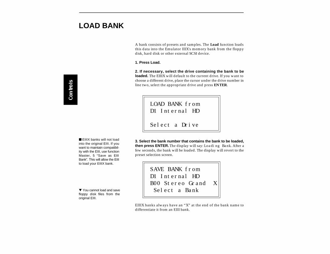
A bank consists of presets and samples. The Load function loadsthis data into the Emulator IIIX's memory bank from the floppydisk, hard disk or other external SCSI device.
1. Press Load.
2. If necessary, select the drive containing the bank to beloaded. The EIIIX will default to the current drive. If you want tochoose a different drive, place the cursor under the drive number inline two, select the appropriate drive and press ENTER.
LOAD BANK fromD1 Internal HD
Select a Drive
3. Select the bank number that contains the bank to be loaded,then press ENTER. The display will say: Loading Bank. After afew seconds, the bank will be loaded. The display will revert to thepreset selection screen.
SAVE BANK fromD1 Internal HDB00 Stereo Grand X Select a Bank
EIIIX banks always have an “X” at the end of the bank name todifferentiate it from an EIII bank.
LOAD BANK
EIIIX banks will not loadinto the original EIII. If youwant to maintain compatibil-ity with the EIII, use functionMaster, 5 “Save as EIIIBank”. This will allow the EIIIto load your EIIIX bank.
You cannot load and savefloppy disk files from theoriginal EIII.
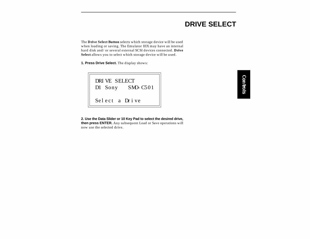
The Drive Select Button selects which storage device will be usedwhen loading or saving. The Emulator IIIX may have an internalhard disk and/or several external SCSI devices connected. DriveSelect allows you to select which storage device will be used.
1. Press Drive Select. The display shows:
DRIVE SELECTD1 Sony SMO-C501
Select a Drive
2. Use the Data Slider or 10 Key Pad to select the desired drive,then press ENTER. Any subsequent Load or Save operations willnow use the selected drive.
DRIVE SELECT

The Multimode Button puts the Emulator IIIX into Multimode,where it can receive on up to 16 MIDI channels at once. Multimodeis used for multi-timbral sequencing and when using a keyboardthat can transmit on more than one MIDI channel at a time. TheMultimode screen is where you assign presets to MIDI channels formulti-timbral sequencing. You can also set the volume and stereopan position for each channel's preset.
1. Press Multimode. The display shows:
MIDI CHANNEL: 01Volume: 127Pan ∆ +00000 Synth Flute
2. Use the cursor buttons to select one of the following param-eters to edit. The volume, pan and preset can be programmed foreach of the 16 MIDI channels. Use the data slider or inc/dec buttonsto change the MIDI channel, Volume or Pan setting. If you do notwant the EIIIX to respond to certain MIDI channels, set the presetfor those channels to “Unassigned” which is located just belowpreset 000.
MIDI CHANNEL: 02Volume: 116Pan ∆ -01 Unassigned
3. After assigning the Preset, Volume and Pan setting for eachMIDI channel, press ENTER. The display will revert to the presetselection screen.
MULTIMODE
Pan∆ adds to the pan set-tings made in the dynamicprocessing module. Settingthe Dynamic Processing Panto 00 allows the Pan∆ param-eter to have total control ofstereo positioning.
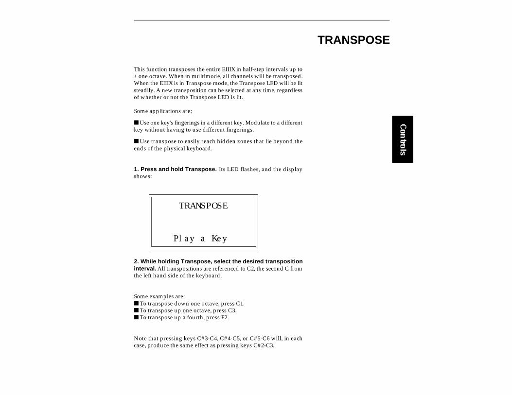
This function transposes the entire EIIIX in half-step intervals up to± one octave. When in multimode, all channels will be transposed.When the EIIIX is in Transpose mode, the Transpose LED will be litsteadily. A new transposition can be selected at any time, regardlessof whether or not the Transpose LED is lit.
Some applications are:
Use one key's fingerings in a different key. Modulate to a differentkey without having to use different fingerings.
Use transpose to easily reach hidden zones that lie beyond theends of the physical keyboard.
1. Press and hold Transpose. Its LED flashes, and the displayshows:
TRANSPOSE
Play a Key
2. While holding Transpose, select the desired transpositioninterval. All transpositions are referenced to C2, the second C fromthe left hand side of the keyboard.
Some examples are: To transpose down one octave, press C1. To transpose up one octave, press C3. To transpose up a fourth, press F2.
Note that pressing keys C#3-C4, C#4-C5, or C#5-C6 will, in eachcase, produce the same effect as pressing keys C#2-C3.
TRANSPOSE
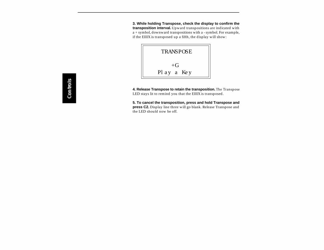
3. While holding Transpose, check the display to confirm thetransposition interval. Upward transpositions are indicated witha + symbol, downward transpositions with a - symbol. For example,if the EIIIX is transposed up a fifth, the display will show:
TRANSPOSE
+G Play a Key
4. Release Transpose to retain the transposition. The TransposeLED stays lit to remind you that the EIIIX is transposed.
5. To cancel the transposition, press and hold Transpose andpress C2. Display line three will go blank. Release Transpose andthe LED should now be off.


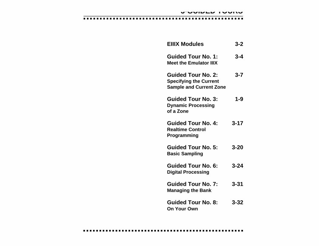
3-GUIDED TOURS
EIIIX Modules 3-2
Guided Tour No. 1: 3-4Meet the Emulator IIIX
Guided Tour No. 2: 3-7Specifying the CurrentSample and Current Zone
Guided Tour No. 3: 1-9Dynamic Processingof a Zone
Guided Tour No. 4: 3-17Realtime ControlProgramming
Guided Tour No. 5: 3-20Basic Sampling
Guided Tour No. 6: 3-24Digital Processing
Guided Tour No. 7: 3-31Managing the Bank
Guided Tour No. 8: 3-32On Your Own
THE EIIIX MODULAR SYSTEM
Each module of the Emulator IIIX affects a certain area of theEmulator IIIX’s operation. You first select a module, then choosewhich parameter with the module you wish to adjust.
Each module will be discussed in detail later on; the following isintended mostly as background information.
Function Buttons: These are the buttons that get you going. LoadBank and Enter load disk data into the EIIIX, Save Bank lets you saveyour work to disk, and Transpose, as you probably suspect, trans-poses the keyboard.
Master/Globals: This module contains functions that affect theoverall keyboard or bank: Master Tune, Memory Available, EraseBank, Rename Bank Save as EIII Bank, various disk utilities, globalMIDI settings and the Special commands.
Sample Management: This module allows you to input soundsfrom the digital I/O port or through MIDI into the bank.
Digital Processing: With this module, you may edit the loop (i.e.infinitely sustain) any portion of the sample.
Preset Management: This module handles the preset “house-keeping duties”, including load presets or entire banks from disk,create, copy, rename, or erase presets and check on how muchmemory space a preset uses up.
Preset Definition: This module lets you change parameterswithin a given preset. You can set up the arpeggiator or MIDIoptions, assign pitch bend and modulation wheels to control variousparameters in realtime, copy or erase zones, edit the sample assign-ment, and set some keyboard parameters (dynamics and crossfadebetween overlapping samples).
Dynamic Processing: This module sets parameters that arefamiliar to those who have worked with analog synthesizers. Youcan set the dynamics by adjusting the VCA envelope, control timbreusing the VCF (filter) and its associated AHDSR envelope generator,modulate the signal with the LFO, tie the keyboard velocity tovarious parameters, set the tuning, attenuation, and delay for eachzone, and more.
Remember: if you want tosave modified presets, savethe altered bank to disk. Other-wise, any changes will be lostas soon as power to the Emu-lator IIIX is interrupted.
Activating a Module, Selecting Functions, andDe-activating a ModuleHere is important background information on how to access thevarious module functions. As the Guided Tours progress, thisinformation will relate to practical examples.
Activating: Each module has an associated switch. Most of theseare in the right-most section indicated by the blue bars next to thebuttons. Pushing the associated switch activates the module, and isindicated by an LED next to the switch. Upon activation, the top lineof the display will show the Module Identifier (such as Master/Globals, Preset Management, etc.). In some cases, upon activationthe display will ask you to specify the current zone or current sample(as described in the next guided tour).
Selecting Functions: Each module includes a printed list of func-tions on the front panel. These functions are available when themodule is active. To select a module function, key in its associatednumber with the keypad.
De-activating: When you’re finished with the module, either pressits button again to de-activate, or activate a new module. Pressingthe Escape button will move you back out of the module by onemenu.
Any time you make a mis-take, get confused or other-wise "lost in the module" andwant to bail out, you can de-activate, then reactivate themodule and try again. TheEscape button works in a simi-lar manner.

Guided Tour No. 1: MEET THE EIIIX
Welcome to the Guided Tours! If you have just met the Emulator IIIXfor the first time, we suggest that you follow these tours until youcomplete the Guided Tours section. This will get you up and runningon the EIIIX in the fastest possible time. Also, you’ll learn some tricksin this section that will come in handy as you play some more withthe Emulator IIIX. This tour covers how to:
Load a Bank from the Hard Disk Select Different Presets within the Bank Load and Save to Floppy Disks Tune the EIIIX to Other Instruments Transpose the Keyboard
Loading a Bank From the Hard DiskPress the Load button. The display says: Load Bank, and shows thename and number of the current bank. Use the data slider to scrollthrough the available hard disk banks. Stop when you find the bankyou want, then press ENTER.
An alternate method of loading a hard disk bank is to press Load,then type in the number of the bank using the numeric keypad. Thedisplay will show the current preset number and name. The cursorwill flash underneath the first digit. Start playing the keyboard andadjust the master volume slider for a comfortable listening level.
Selecting Different PresetsThe bank you just loaded contains several presets. To call up a newcurrent preset, use the up/down cursor buttons to position thecursor under the preset number, then use the keypad underneath thedisplay. Note that leading zeroes must be entered for preset num-bers (i.e. type 0, 0 and 2, not just 2, to call up preset 002). Now type0, 0 then 2 on the keypad; these will replace the numbers indicatedby the flashing cursor.
Now call up more presets. If you enter a number for which there isno preset, the display will list the entered preset number and say“Empty Preset”. Try again.
To scroll through the presets available in the bank, move the dataslider. The various preset names will scroll on the lower display line.When this line shows the desired preset, press ENTER to make thatthe current preset. This is an alternative preset selection method.
Yet another method is to use the left and right cursor buttons toincrement or decrement through the presets. This method allowsyou to arrange your presets in the proper order, then access themsequentially with a single press of a button.
When you’re ready to check out some more sounds, proceed.
Saving Data to a Hard DiskThe hard disk drive is used to make permanent backups of yourwork. The capacity of the floppy drive is too small to make efficientback-ups, therefore only the hard disk (or its equivalent) can be usedfor sound storage.
To Save a Bank to Disk:
1. Press the Save button. Position the cursor under the drivenumber in line two. Select the disk drive using the data slider. PressENTER.
2. Use the Data Slider to select an Empty Bank. Empty banks areindicated as such, along with their bank number on line three. Savingto a non-empty bank erases the bank that was previously savedthere.
3. Press ENTER to save the Bank. The display will revert to thepreset selection screen.
Tuning the EIIIX to Other InstrumentsRefer to the Master/Globals module, 1. Master Tune. This functiondemonstrates how the Emulator IIIX uses the data slider to adjust aparameter. Play the keyboard while adjusting the data slider tochange the overall tuning.

Transposing the KeyboardRefer to the function button Transpose. While holding the transposebutton, play a key on the keyboard in the lower two octaves. Thesecond C from the bottom (C2) corresponds to normal or no transpo-sition. All transpositions are based from this C2 key. For example,pressing the G key above C2 will transpose the keyboard up a perfectfifth. If the keyboard has been transposed, the transpose LED willstay lit. Press and hold the transpose button while pressing C2 toreturn to normal transposition.

Guided Tour No. 2: SPECIFYING THECURRENT SAMPLE and THE CURRENT ZONE
The Emulator IIIX has two modules dedicated exclusively to pro-cessing samples within a preset: Digital Processing and SampleManagement. Each sample stored in a bank can be processed by theDigital Processing module independently. Therefore, we need a wayto specify the current sample, which is the individual sample to beprocessed.
The concept of the current sample is important. To process onesample out of a preset, assign the current sample to be that onesample, and process it.
Zones are sections of the keyboard which can be selected to applyDynamic Processing parameters or to be copied, erased or loadedfrom another preset. A copied zone contains samples as well asanalog parameters. A zone can be one key or the entire keyboardrange.
To Identify Which Keyboard Keys Belong to Which Sample:
1. Activate the Preset Definition module.
2. Select 2. Edit Assignment.
EDIT ASSIGNMENTP00 pri D2p01 Sample NameNo Secondary Sample
3. Play a key on the keyboard. Line two shows the preset numberand the last key pressed. Line three shows the primary sampleassigned to the key, and line four shows the secondary sample, ifany, assigned to the key. As you run your fingers up and down thekeyboard, the primary and or secondary sample numbers willchange indicating the keyboard range of those samples. Moving thedata slider will also show you the sample boundaries.

4. Choose a sample and press ENTER. The display now shows therange of the current zone on the upper line of the display. Don’t playany keys but press ENTER again. Now the display shows somethinglike this, where XX is the name of the key (such as D2).
EDIT ASSIGNMENT
Zone: XX to XX Select High Key
Specifying the Zone of the Dynamic Process-ing ModuleNow that we know how many samples there are in the preset, andthe range covered by each sample, let’s specify a range of keys to bealtered by the Dynamic Processing Module, starting with the lowestkey.
1. Activate the Dynamic Processing module.
2. Select 0. Select Zone.
3. Specify the range of the zone. The display instructs you to“Select Low Key”. Press the lowest key on the keyboard, then pressthe ENTER button (whose LED is now flashing). The display theninstructs you to “Select High Key”. Press a key on the keyboard nearthe top of the keyboard, then press ENTER. The display now showsthe current zone and prompts you to “Select a Submodule”.
At this point, you can begin modifying the sounds in the bank withthe Dynamic Processing module. The assigned current zone willremain as is until you either change the current zone assignment,change presets, or load another bank. If you switch between mod-ules, the current zone remains as assigned (unless you select theDigital Processing Module, which will be a subject of a later tour).
Before proceeding, look over Dynamic Processing, 0. Select Zone tohelp reinforce what you’ve learned. Now that you know what a zoneis and how to specify it, we’ve reached the end of this tour. Feel freeto come back any time to refresh your memory. In the next tour, we’llsee how to modify samples with the Dynamic Processing section.

Guided Tour No. 3: DYNAMIC PROCESSINGOF A ZONE
You must re-trigger a note tohear any changes. Holdingdown a note and playing theslider will not change thesound; you must play the noteafter changing the slider tohear the results. This is truewhen making any changes tothe sound, not just while you’rein the filter function or the Dy-namic Processing Module.
The Dynamic Processing module consists of several interestingsound processing functions. Let’s start with the Filter and VCAsections, as they are among the most important.
The VCA function contains 32 Voltage Controlled Amplifiers thatcontrol the amplitude envelope of a sound. The filter functioncontains 32 Voltage Controlled Filters that control the timbre of asound. (Note: The voltage controlled filters and amplifiers are actuallyimplemented digitally. The names VCF and VCA are kept for EIII compat-ibility.)
Working with the FilterYou could activate the Filter Setup function directly by keying in 3.However, let’s investigate another way to select the filter function.Move the data slider to catalog the various Dynamic Processingfunctions. When the display shows function 3. VCF, press ENTER.
To Change the Filter Cutoff Frequency:
1. Activate the Dynamic Processing module, 3. VCF. The displayshould look something like this:
VCF
Cutoff: 74040 HzQ: 0%
Play with the up and down cursor buttons. Note how you can movethe cursor under the various parameters to be adjusted. For now,move the cursor under the Cutoff frequency on line three.
2. Select the filter cutoff frequency. To do this, vary the data slider.Note how the numbers to the right of cutoff change. Lower numbersmean a lower filter cutoff frequency (less high frequencies). Highernumbers mean a higher filter cutoff frequency (more high frequen-cies). Observe how only the notes within the current zone areaffected by the slider setting.

Now might be a good time to mention that although we are changingthe sounds in the bank, the sounds on the disk remain unchanged.This is because we haven’t saved the bank to disk. You can foolaround with the bank sounds as much as you want without havingto worry about altering the original sounds on the disk.
To Change Filter Q:
VCF
Cutoff: 22049 HzQ: 0%
1. Move the cursor to the Q% on line four. Vary the slider to changethe sharpness of the sound. Higher numbers give a sharper sound.Again, this affects only the range of notes covered by the currentzone. Set the Q at about 60 and proceed.
2. Move the cursor back to Cutoff on line three. Vary the dataslider. Note how this produces a sort of wa-wa effect. Remember,you have to re-trigger the key to hear the results of changing the Q.Set Cutoff to 200 Hz and Q to about 50. The range of notes coveredby the current zone should sound muted.
To Change the Filter Cutoff Envelope:
1. Select page two by pressing the right cursor arrow.
VCF
Tracking: +1.00Envelope Amt: 0%
Investigate the effects of envelope control over the filtered sound bymoving the cursor to the Envelope Amount. Use the slider to set avalue of +40%. This allows the envelope to control the filter cutofffrequency.

2. Select page three by pressing the right cursor.
VCF Attack: 0.20sHold: 0.00sDecay: 0.00sSustain:99% Rel:0.40s
Move the cursor under the Attack time on line one and vary theslider. With larger values, it will take more attack time for the filterfrequency to go from lowest to highest cutoff frequency. Vary thevarious envelope parameters, and observe the effect these changeshave on the sound.
To check out inverted envelopes, set the envelope parameters asfollows:
VCF Attack: 0.20sHold: 0.00sDecay: 0.00sSustain:99% Rel:0.40s
Play and hold a chord. This is a non-inverting envelope in the sensethat the envelope increases the filter cutoff frequency above theinitial cutoff. To select an inverting envelope where the cutoffdecreases below the initial cutoff, press the left cursor arrow.
VCF
Tracking: +1.00Envelope Amt: 0%
3. Move the cursor to Envelope Amount and select -40% to invertthe envelope. The envelope effect is not all that noticeable when youplay a chord. This is because the envelope forces the cutoff frequency

in a negative direction. Since the cutoff frequency is already fairlylow, it can’t go that much lower. Now go back to the cutoff frequencyand increase it. The effect will be far more noticeable since there willbe more range available for the negative going envelope excursion.
If you feel like experimenting, play with the Tracking control toaffect the way the filter frequency tracks the keyboard pitch.
Before proceeding with the tour, set Cutoff Frequency to 22049, Q to00, Envelope Amount to +00, and Tracking to 1.00. Set the envelopeAttack to 0.00s, Hold to 0.00s, Decay to 0.00s, Sustain to 100%, andRelease to 0.49s. After entering these values, press ENTER to returnto the Module Identifier.
Fun With Voltage Controlled AmplifiersIn preparation for the following experiments, let’s change theCurrent Zone to include the entire keyboard.
1. Select Submodule 0. Select Zone. Move the data slider to thebottom of its travel and press ENTER. Now move the data slider tothe top of its travel and press ENTER again. You have now specifiedthe entire keyboard as the current zone.
2. Select the 2. VCA function. The display shows:
VCALevel: 100%Pan: + 0%L | R
3. Select the next page of the VCA controls with the right cursor.
VCA Attack: 0.20sHold: 0.00sDecay: 0.30sSustain:50% Rel:0.60s

Move the cursor under the various envelope parameters and ob-serve how different settings affect the sound. Before moving on,make sure you have a sound that is fairly sustained with little or noenvelope attack time.
Other Dynamic Processing Options
1. Select 1. Setup. Note how the tuning, delay, and chorus controlsaffect the sound.
2. Add some Low Frequency Oscillator effects. Select the 4. LFOfunction. The display shows:
LFORate: 4.25HzShape: triangleDelay: 0.00s
If the LFO rate is different, change the rate so that it is about 4.25 Hz.
3. Use the right cursor/page button to move to the next page ofthe LFO controls. The display will show something like this:
LFOVariation: 0%LFO->Pitch: 0%LFO->Cutoff 0%
Position the cursor under each display option. Vary the data sliderand observe how this affects the sound. Adding LFO to Cutoff mightnot sound all that noticeable. If you want a more obvious effect,bounce back to function 3. VCF and set the Cutoff to about 200 Hzand Q to about 50. This should make the LFOs effect more noticeable.

4. Select page three of the LFO controls. The display will show:If the LFO settings aren’t to your liking, use the left cursor/pagebutton to change the LFO rate, delay, and variation.
LFO
LFO->Pitch: 0%LFO->Cutoff 0%
The Auxiliary Envelope
1. Select 5. Auxiliary Envelope. The display shows the first page:Move the cursor under Destination on line two, and use the data
AUXILIARY ENVELOPE
Dest: offEnvelope Amt: 0%
slider to scroll through the auxiliary envelope destinations. SelectPitch as the destination, then set the Envelope Amount to -50%.
2. Select the next page using the right cursor. Set the parametersso that the display looks like this:
AUX Attack: 0.00sHold: 0.00sDecay: 0.40sSustain:99% Rel:1.65s
Now play the keyboard. Notes will bend up, since we are using aninverted envelope, to pitch and then hold there. This is an effectcommon in many natural sounds.
Vary the various envelope parameters, and observe the effect thesechanges have on the sound.
Understanding VelocityBy now you probably have a pretty messy sound as a result of allthese exercises. Let’s start with a clean slate.
1. Press the Load Bank button, then ENTER to re-load the bank.
2. When the bank is loaded, activate the Dynamic Processingmodule.
3. Specify a zone. Let’s make the entire keyboard the current zone.Since the default zone is the entire keyboard we don’t have to doanything!
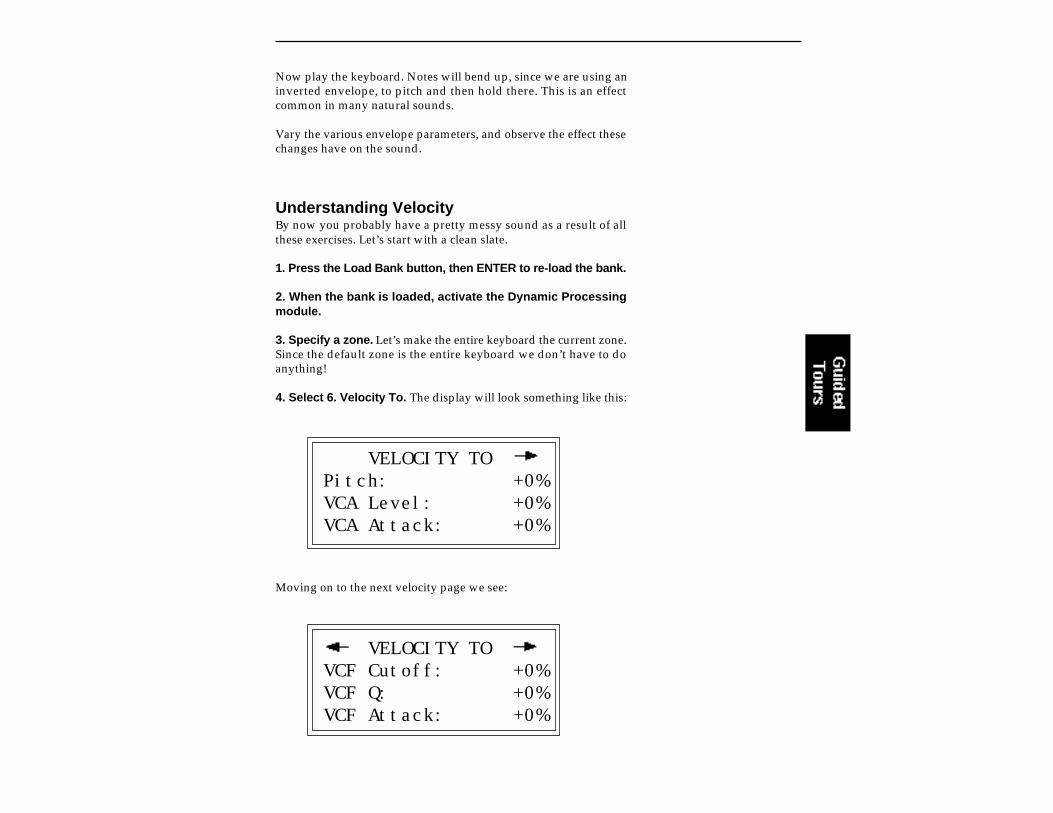
4. Select 6. Velocity To. The display will look something like this:
VELOCITY TOPitch: +0%VCA Level: +0%VCA Attack: +0%
Moving on to the next velocity page we see:
VELOCITY TOVCF Cutoff: +0%VCF Q: +0%VCF Attack: +0%
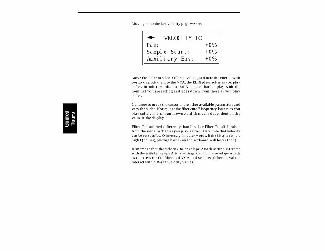
Moving on to the last velocity page we see:
VELOCITY TOPan: +0%Sample Start: +0%Auxiliary Env: +0%
Move the slider to select different values, and note the effects. Withpositive velocity sent to the VCA, the EIIIX plays softer as you playsofter. In other words, the EIIIX equates harder play with thenominal volume setting and goes down from there as you playsofter.
Continue to move the cursor to the other available parameters andvary the slider. Notice that the filter cutoff frequency lowers as youplay softer. The amount downward change is dependent on thevalue in the display.
Filter Q is affected differently than Level or Filter Cutoff. It raisesfrom the initial setting as you play harder. Also, note that velocitycan be set to affect Q inversely. In other words, if the filter is set to ahigh Q setting, playing harder on the keyboard will lower the Q.
Remember that the velocity-to-envelope Attack setting interactswith the initial envelope Attack settings. Call up the envelope Attackparameters for the filter and VCA and see how different valuesinteract with different velocity values.

Guided Tour No. 4: REALTIME CONTROLPROGRAMMING
Ever wanted to add vibrato to a grand piano? Or bend its pitch? TheRealtime Control functions in the Preset Definition module can dothis, and lots more.
Pitch-BendingFirst, let’s check out pitch-bending. Pitch-bend can be enabled ordisabled for any zone within a preset. Let’s have pitch bend affectonly the lower half of the keyboard. Activate Dynamic Processing,0. Select Zone. Specify the upper half of the keyboard as the currentzone.
Next key in Dynamic Processing, 8. Realtime Control Enable. Usethe cursor/page buttons to see a list of modulation destinations.Pitch will be set to On. Press Off, and like magic, you can now pitch-bend only the lower half of the keyboard. If modulation does notseem to be affecting a zone, make sure that modulation is enabled.
Want to change the pitch bend range? Activate the Preset Definitionmodule, 6. MIDI.
Modulation Wheel DestinationsThe Emulator IIIX offers two modulation options: Pre-programmed,which adds a constant, selectable amount of modulation, and Real-time, where the player adds in modulation by using one of thewheels or other controller.
Each Emulator IIIX wheel can be assigned to a particular destination.For example, if the left wheel is assigned to pitch, then rotating thewheel bends pitch. If assigned to the filter, rotating the wheel variesthe cutoff frequency.
Let’s set up for the next part of the tour. Choose preset 01 as thecurrent preset if it is not already selected. Activate the DynamicProcessing module and assign the entire keyboard as the currentzone if necessary. Select 8. Realtime Control Enable. Use the cursor/page buttons to select On for all of the Enable options. This will makeit easier to hear the results of the next series of experiments.

Now activate the Preset Definition module, 0. Realtime Controls. Tomake “live” playing as simple as possible, the display works some-what differently for this module. The display shows:
REALTIME CONTROLS1 Left Wheel1 Pitch Select a Controller
Use the data slider to scroll through the available Realtime Controlsources and their currently assigned destinations.
Emulator IIIX Control Sources1: Left Wheel2: Right Wheel3: Pressure4: Control Pedal (plugs into rear panel pedal jack)5: MIDI Control A (can be assigned to any MIDI controller #)6: MIDI Control B (can be assigned to any MIDI controller #)7: Footswitch 1 (on your MIDI controller)8: Footswitch 2 (on your MIDI controller)
Emulator IIIX Modulation Destinations0: Off 5: LFO -> Cutoff1: Pitch 6: LFO ->VCA2: VCF Cutoff 7: Pan3: VCA Level 8: Attack4: LFO->Pitch 9: Crossfade
EIIIX Footswitch Destinations0: Off 4: Arpeggiator Latch1: Sustain 5: Preset Increment2: Cross/Switch 6: Preset Decrement3: Arpeggiator On/Off
Each of the modulation destinations (0-9) can be controlled bycontrol source 1, 2, 3, or 4, or via data sent over MIDI. Each of thefootswitch destinations (0-6) can be controlled by sources 7 and 8.
You’ll be happy to know that Realtime Control settings are memo-rized for each individual preset, so if desired, each preset can reactto the Realtime controls and MIDI controllers in different ways.

Selecting a Control Source and Destination
1. Activate the Preset Definition module, 0. Realtime Controls.
2. Select the left wheel as a control source. Move the cursor downto the next line. The display will direct you to “Select a Destination”.The left wheel should be assigned to 1: Pitch. Vary the wheel andcheck that the keyboard pitch is indeed affected. If sections of thekeyboard are not affected, check that pitch control is enabled (Dy-namic Processing, 8. Realtime Control Enable).
Now try assigning the left wheel to 2: VCF Cutoff. Rotating the wheeltowards you should produce a more muted sound.
If you assign 3: VCA Level, the left wheel will affect overall volume.
If you feel adventurous, check out the other control destinations.Note that if you select a destination that is already specified for oneof the other control sources, the old assignment will be de-selectedand that control source will be turned off (0).
Think about it for a bit... the left wheel can control a destination, theright wheel can control a different one (as can the pedal), and thereare MIDI control possibilities as well. These assignments can bedifferent for each preset, and particular controller destinations canbe disabled for different presets and samples. We’re talking versatilehere, so if you feel like taking out the next couple of hours andchecking out all the possibilities, by all means, do so!
Oh yes, and there are footswitches too. But before experimentingwith the footswitches (sources 7 and 8), we need to understand thedifference between looped and unlooped sounds. Basically, a sus-tain looped sound is one where a portion of the sound is put into aninfinite repeat loop for as long as you hold down the key. This issimilar to the infinite repeat function on digital delay lines. Loopingallows you to sustain a normally non-sustaining sound for as long asyou like. An unlooped sound is not artificially sustained, and there-fore lasts its normal length.
Keeping this in mind, refer to the Preset Definition module, 0.Realtime Controls, footswitch destinations 0-6. Assign various func-tions to the footswitches. You will find that some sounds lendthemselves to the sustain function better than other sounds, and weheartily encourage you to experiment.
One control source can con-trol up to six destinations. Thiscan be done by setting morethan one source to the samecontroller number in the MIDIsubmodule (Preset Definition,6).
For example, by setting rightwheel and pressure to 01, (inthe MIDI submodule) the mod.wheel on your controller willnow control two sources in therealtime controls submodule.

Sampling involves more than just sticking a microphone in front ofsomething—sampling is an art. This guided tour gives you thebasics, and also lays the groundwork for the guided tour of theDigital Processing Module. In preparation for this guided tour,please read section 5, Sample Management module.
Sampling with a DAT RecorderThe EIIIX can sample from either analog or digital sources. YourEIIIX may or may or may not be equipped with the optional analoginputs. Without the analog inputs youwill need to have some sort ofdevice with a digital audio output such as a DAT or stand-aloneA/D converter unit. To sample from a DAT recorder, connect thedigital output of the DAT to the digital input of the EIIIX. Either theAES/EBU or the consumer S/PDIF formats can be used. By puttingthe DAT recorder in record/pause mode you can sample directlyinto the EIIIX just as if it had analog sample inputs. Playing a DATtape works the same way. For this tour, plug a microphone into theDAT recorder.
Sampling with the Optional Analog InputsIf you wish to use the analog sampling inputs for this guided tour,simply connect a microphone directly to either the left or rightanalog input.
1. Activate the Master/Globals module.
2. Select 3. Erase Bank. Answer Yes to the display's query. Thisclears out the memory, which gives us maximum sampling time.
3. Activate the Sample Management Module, 5. Setup. Thedisplay shows:
SETUP Gain: -10dBThresh: |L: on |R: on |
Guided Tour No. 5: BASIC SAMPLING
To connect a standard XLRtype microhone to the analoginput of the EIIIX, an adaptercable wired as shown aboveshould be used.
To connect the EIIIX to S/PDIF format machines, anadapter cable wired as shownabove shoud be used. Alwaysuse video-grade cabling whenconnecting digital I/O.

If you are sampling in mono, move the cursor to the input that youare not using and turn it off with the On/Off buttons. Otherwise,leave both channels on.
4. Use the right cursor/page button to view the next page of theSetup section.
SAMPLE SETUPSource: Digital44.1KLength: 5.5secs200.8 secs Available
Check the available sampling time. This will vary depending on howmuch memory you have in your EIIIX.
5. Change the source using the data slider to match the type ofinput you are using. If you are using the analog sample inputs, setthe source to either Analog 29.4 kHz or Analog 44.1 kHz. If you areusing the digital inputs, set the source to Digital 32 kHz, 44.1 kHz or48 kHz to match the sample rate of your input device. (If the digitalsample is set incorrectly the sample will play back at the wrongpitch.)
6. Use the right cursor/page button to go back to the first page.
SETUP Gain: -10dBThresh: |L: on |R: on |
With the connection peak into the microphone, you should see theVU meter move, indicating that the EIIIX is receiving signal.
If you are using the analog inputs, place the cursur on line one of thedisplay and use the data slider to adjust the input gain. Speak into themicrophone and observe the bar graph display. Adjust the gain sothat the peak bar comes close to the extreme right side withoutactually reaching it. (The gain control has no effect on the digitalinput.)
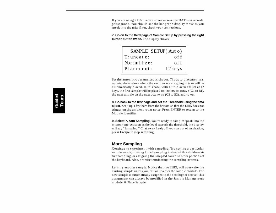
If you are using a DAT recorder, make sure the DAT is in record/pause mode. You should see the bar graph display move as youspeak into the mic; if not, check your connections.
7. Go on to the third page of Sample Setup by pressing the rightcursor button twice. The display shows:
SAMPLE SETUP(Auto)Truncate: offNormalize: offPlacement: 12keys
Set the automatic parameters as shown. The auto-placement pa-rameter determines where the samples we are going to take will beautomatically placed. In this case, with auto-placement set at 12keys, the first sample will be placed on the lowest octave (C1 to B1),the next sample on the next octave up (C2 to B2), and so on.
8. Go back to the first page and set the Threshold using the dataslider. Set it up a few bars from the bottom so that the EIIIX does nottrigger on the ambient room noise. Press ENTER to return to theModule Identifier.
9. Select 7. Arm Sampling. You’re ready to sample! Speak into themicrophone. As soon as the level exceeds the threshold, the displaywill say “Sampling.” Chat away freely . If you run out of inspiration,press Escape to stop sampling.
More SamplingContinue to experiment with sampling. Try setting a particularsample length, or using forced sampling instead of threshold-sensi-tive sampling, or assigning the sampled sound to other portions ofthe keyboard. Also, practice terminating the sampling process.
Let’s try another sample. Notice that the EIIIX, will overwrite theexisting sample unless you exit an re-enter the sample module. Thenew sample is automatically assigned to the next higher octave. Thisassignment can always be modified in the Sample Managementmodule, 6. Place Sample.

Saving the SampleTo save the sample as part of a preset, de-activate the Sample/Management module. Since memory was cleared prior to sampling,the EIIIX created a preset (00) called “Untitled Preset.” This is thepreset that holds your new sample. Had you sampled into a bankwith existing presets, the sample would have been stored with thecurrent preset.
Remember, this guided tour is intended simply as an overview togive you a feel for the sampling process. Good sampling requiresskill, patience, and above all, practice!
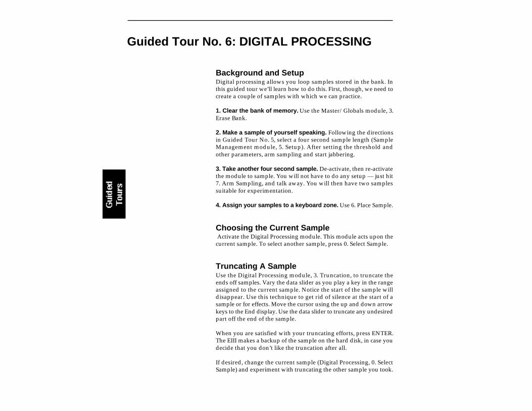
Guided Tour No. 6: DIGITAL PROCESSING
Background and SetupDigital processing allows you loop samples stored in the bank. Inthis guided tour we’ll learn how to do this. First, though, we need tocreate a couple of samples with which we can practice.
1. Clear the bank of memory. Use the Master/Globals module, 3.Erase Bank.
2. Make a sample of yourself speaking. Following the directionsin Guided Tour No. 5, select a four second sample length (SampleManagement module, 5. Setup). After setting the threshold andother parameters, arm sampling and start jabbering.
3. Take another four second sample. De-activate, then re-activatethe module to sample. You will not have to do any setup — just hit7. Arm Sampling, and talk away. You will then have two samplessuitable for experimentation.
4. Assign your samples to a keyboard zone. Use 6. Place Sample.
Choosing the Current Sample Activate the Digital Processing module. This module acts upon thecurrent sample. To select another sample, press 0. Select Sample.
Truncating A SampleUse the Digital Processing module, 3. Truncation, to truncate theends off samples. Vary the data slider as you play a key in the rangeassigned to the current sample. Notice the start of the sample willdisappear. Use this technique to get rid of silence at the start of asample or for effects. Move the cursor using the up and down arrowkeys to the End display. Use the data slider to truncate any undesiredpart off the end of the sample.
When you are satisfied with your truncating efforts, press ENTER.The EIII makes a backup of the sample on the hard disk, in case youdecide that you don’t like the truncation after all.
If desired, change the current sample (Digital Processing, 0. SelectSample) and experiment with truncating the other sample you took.

Looping A SampleIf you haven’t yet done so, activate the Digital Processing Moduleand assign the current sample.
1. Select 2. Loop to graphically see how looping affects asample. Since the loop function is on, if you play and hold a key inthe current sample, it will play indefinitely.
2. Try modifying the loop. Adjust the Start and Length values. Notethat if the length equals the full length of the sample, you will not beable to set a new start point. Reduce the length, and you should beable to adjust the start point. For practice, try looping individualwords or sentence fragments.
A Practice Sampling SessionPlug a microphone into the rear panel right Sample Input jack (orthrough a DAT into the digital I/O).
1. Erase all memory (Master/Globals, 3. Erase Bank).
2. Set the Sample Source for either Analog or Digital sampling(Sample Management, 5. Setup). “Source” is located on the secondpage in the Setup submodule. If you are using the digital inputs,match the sample rate to that of your DAT recorder or the sample willplay back at the wrong pitch.
3. Set the level (Sample Management, 5. Setup). Sing Ahhhh intothe microphone. (This is an easy sound to loop.) The VU level shouldnot quite reach the top of its range. Adjust the gain using the dataslider, until a good level is attained.
4. Set the threshold (Sample Management, 5. Setup). This shouldbe set about five or six bars from the left. When the input soundexceeds this level, recording will start.
5. Select 7. Arm Sampling, to arm the sampling process. OK,now get ready to sing Ahhhhh.
6. Sing Ahhhhh! When you are out of breath, press ENTER to stopsampling.
7. Play the keyboard in the assigned range to hear the results.The sound should default to the lower keyboard range, C1-B1.
8. Truncate the silence off of the beginning and end of thesound. Activate the Digital Processing module. The EIIIX willdefault to the only sample in the unit, which is the one you just made.

Now select 3, Truncation to enable the truncation function. Adjustthe start and end points by moving the slider to remove any silenceor unwanted portion of the sound. You must play the keyboard afteryou move the data slider in order to hear the results of the sliderchange. Press ENTER, then No to exit truncation.
9. Activate the Digital Processing module, 2. Loop. Now we areready to loop the sound.
To loop, first move the data slider to make the loop length about halfa second long. Next, move the start point into the sustained portionof the ahhh sound so that the ticking sound becomes softer. The ideais to loop the “hhh” portion of the “ahhh” but not the “a “ part. Theloop length can be adjusted so that it matches the rhythm or waver-ing of the sound. When you get a fairly good loop press ENTER. Thedisplay says: “Auto Correlate? Y/N.” Press Yes. You now shouldhave a fairly good loop. If not, adjust the start point and again AutoCorrelate. It takes practice, but you’ll get it.
That’s it! Feel free to play around with other digital and dynamicprocessors such as the filter, chorus and LFO.
So basically, these are the steps you will go through every time youhave a sampling session:
Take the sample Truncate the sample Loop the sample, if desired Assign the sample to a keyboard position Continue to refine and make presets
Of course, you will probably develop your own order and style ofsampling techniques.
The purpose of this guided tour is to acquaint you with the conceptof looping. There is much more to the subject than simply foolingaround with looping words from a spoken sample. Please remembertoo that looping is a very complex process which requires a greatdeal of practice to achieve proficiency. The best way to fully under-stand looping is to experiment with a variety of signals.
Time To Save?Maybe you haven’t created any masterpieces during theseexperiments...but maybe you have. If you want to save a preset todisk, by all means do so.
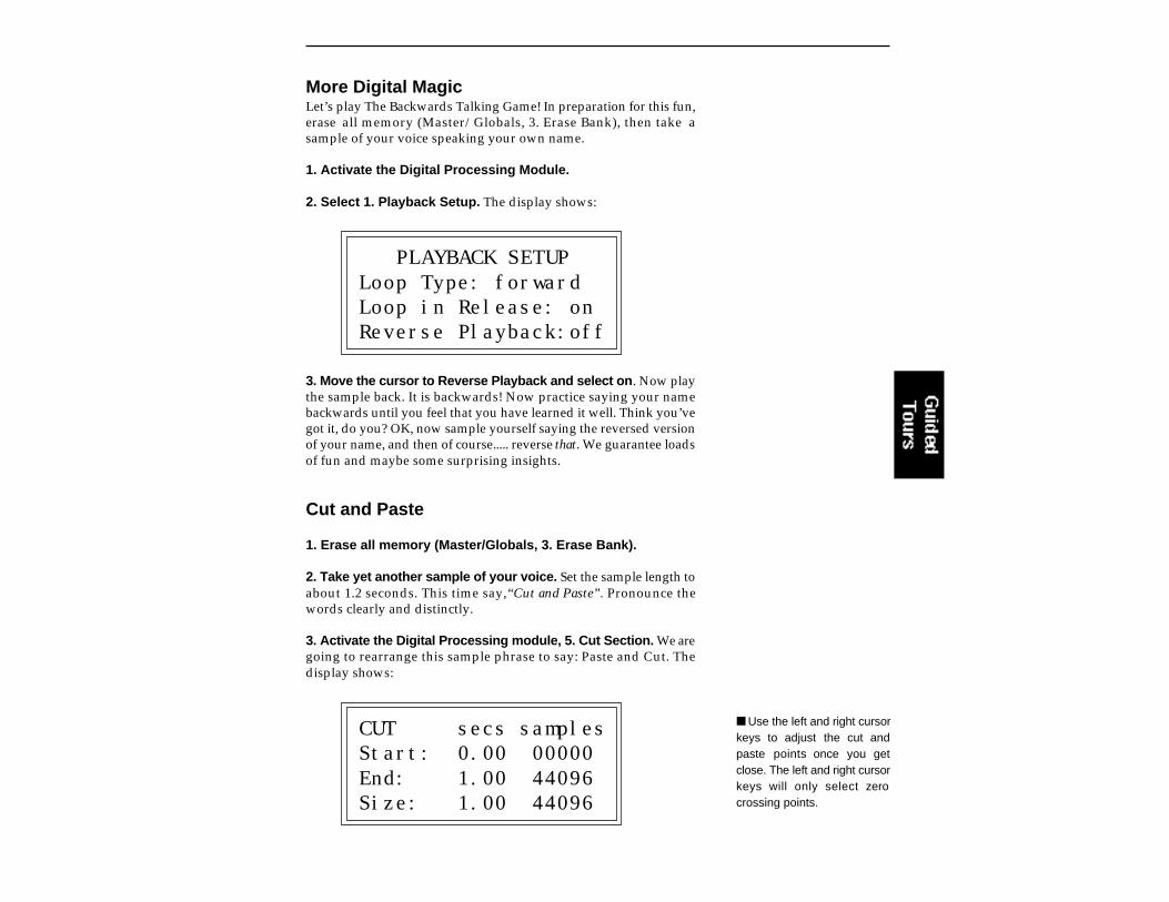
More Digital MagicLet’s play The Backwards Talking Game! In preparation for this fun,erase all memory (Master/Globals, 3. Erase Bank), then take asample of your voice speaking your own name.
1. Activate the Digital Processing Module.
2. Select 1. Playback Setup. The display shows:
PLAYBACK SETUPLoop Type: forwardLoop in Release: onReverse Playback:off
3. Move the cursor to Reverse Playback and select on. Now playthe sample back. It is backwards! Now practice saying your namebackwards until you feel that you have learned it well. Think you’vegot it, do you? OK, now sample yourself saying the reversed versionof your name, and then of course..... reverse that. We guarantee loadsof fun and maybe some surprising insights.
Cut and Paste
1. Erase all memory (Master/Globals, 3. Erase Bank).
2. Take yet another sample of your voice. Set the sample length toabout 1.2 seconds. This time say,“Cut and Paste”. Pronounce thewords clearly and distinctly.
3. Activate the Digital Processing module, 5. Cut Section. We aregoing to rearrange this sample phrase to say: Paste and Cut. Thedisplay shows:
CUT secs samplesStart: 0.00 00000End: 1.00 44096Size: 1.00 44096
Use the left and right cursorkeys to adjust the cut andpaste points once you getclose. The left and right cursorkeys will only select zerocrossing points.
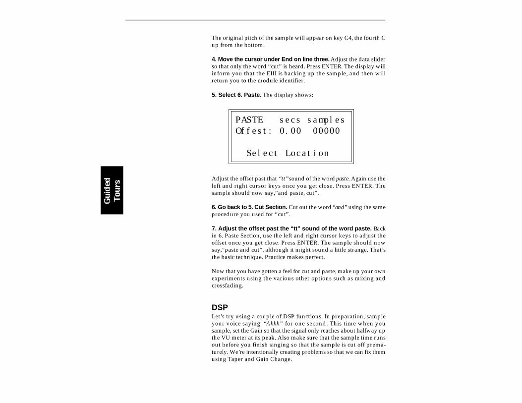
The original pitch of the sample will appear on key C4, the fourth Cup from the bottom.
4. Move the cursor under End on line three. Adjust the data sliderso that only the word “cut” is heard. Press ENTER. The display willinform you that the EIII is backing up the sample, and then willreturn you to the module identifier.
5. Select 6. Paste. The display shows:
PASTE secs samplesOffest: 0.00 00000
Select Location
Adjust the offset past that “tt” sound of the word paste. Again use theleft and right cursor keys once you get close. Press ENTER. Thesample should now say,”and paste, cut”.
6. Go back to 5. Cut Section. Cut out the word “and” using the sameprocedure you used for “cut”.
7. Adjust the offset past the “tt” sound of the word paste. Backin 6. Paste Section, use the left and right cursor keys to adjust theoffset once you get close. Press ENTER. The sample should nowsay,”paste and cut”, although it might sound a little strange. That’sthe basic technique. Practice makes perfect.
Now that you have gotten a feel for cut and paste, make up your ownexperiments using the various other options such as mixing andcrossfading.
DSPLet’s try using a couple of DSP functions. In preparation, sampleyour voice saying “Ahhh” for one second. This time when yousample, set the Gain so that the signal only reaches about halfway upthe VU meter at its peak. Also make sure that the sample time runsout before you finish singing so that the sample is cut off prema-turely. We’re intentionally creating problems so that we can fix themusing Taper and Gain Change.

First, let’s boost the gain to full level using one of the digital tools,Gain Change. The term for this operation is called normalization.
1. Activate the Digital Processing module.
2. Select 8, Digital Tools, 2-Change Gain. The display shows:
GAIN secs samplesStart: 0.00 00000End: 1.00 44096Size: 1.00 44096
We want to normalize the entire sample (which is already selected),so just press ENTER. The display now shows:
GAIN CHANGE
Amount: +00dB +XXdb = Normalize
where XX is the amount of gain needed to achieve normalization orfull level. Set the amount of gain so that it matches the normalizationreading and press ENTER. The display shows:
FADE secs samplesStart: 0.00 00000End: 1.00 44096Size: 1.00 44096
We don’t want a fade in this example, so simply press ENTER toaffect the gain change. The sample should now be at a highervolume. Note that you can use the Digital Processing module, 9.Undo to cancel the effects of Gain Change. Use this feature to furtherexperiment with different Gain Change settings.
3. Select 7, Taper. Now let’s taper the end of the sample so that itsmoothly fades out instead of ending in a thump. The display shows:

TAPER secs samplesStart: 0.00 00000End: 1.00 44096Size: 1.00 44096
Move the start point to about 0.70 seconds and press ENTER. Thedisplay changes to:
TAPERStart Amount: 0.00dbEnd Amount: -96dbType: Linear
The Start and End amounts on lines two and three are already at thecorrect settings. There will be no attenuation at the Start point,tapering to full attenuation at the End point of the sample.
4. Move the cursor under the curve Type on line four. SelectExponential Curve 2, then press ENTER. The sample should nowsmoothly fade out instead of ending abruptly. And remember thatDigital Processing, 9. Undo will cancel the effects of Taper. You canuse this feature to further experiment with different Taper settings.
Guided Tour No. 7: MANAGING THE BANK
The following functions don’t necessarily do terribly glamorousthings, but they are exceedingly useful for managing your banks ofsound data. This guided tour acquaints you with these utilities. Tosee how they work, load any bank from the hard disk.
Erasing A PresetActivate the Preset Management module, 3. Erase Preset and erasepreset 01. Don’t worry, it will just be gone from the bank, not the disk.And we can get it back anyway by...
Loading A PresetRefer again to the Preset Management module, 1. Load Preset. Thistime load preset 01. Now it’s back in the bank again.
This is the basic method for creating a bank with presets from otherbanks. The bank can only be saved as a whole. Therefore, individualpresets are loaded into the bank, and when the bank is arranged toyour specifications, it is then saved to disk.
Other Bank Management FunctionsThe other bank management functions, including copy, rename,create, and preset size, are pretty much self-explanatory. Refer to thePreset Management module, 4. Copy Preset, 2. Rename Preset, 5.Create Preset, and 6. Preset Size. Try these various functions to get afeel for how they work.

Guided Tour No. 8: ON YOUR OWN
The proceeding guided tours cover only the basics. To cover everypossibility of how to use the XP would drown you in words. It’sbetter that you just start playing! The best way to learn the EIIIX is topower up and dive right in. Remember, you can experiment as muchas you want on stuff in the bank. You have to actually save the bankto disk in order to alter the contents of the disk. In case you’re anervous type, you can even lock the disk.
Try to spend some time not playing, but rather practicing, with theinstrument. After you’re a bit more familiar with the EIIIX, read theManual and delve deeply into a particular module or function. TheEmulator Three XP is like an audio construction set, where soundscan be captured, held, processed, mutated, sped up, slowed down...and so much more. Take advantage of all it has to offer.
The more you practice with your EIIIX, the more you’ll be able to putyour personal stamp on the music you play. And when you do play,you’ll know the instrument well enough so that you are free toconcentrate solely on your music. Because that's what matters.


4-MASTER/GLOBALS
1. MASTER TUNE 4-22. RENAME BANK 4-33. ERASE BANK 4-44. DYNAMIC ALLOCATION 4-55. SAVE AS EIII BANK 4-66. MEMORY AVAILABLE 4-77. DISK UTILITIES 4-8
0. SCSI Setup 4-91. Mount Drives 4-102. Rename Disk Bank 4-103. Erase Disk Bank 4-114. Copy Software 4-125. Lock Bank and Drive 4-136. Disk Status 4-147. Format Disk 4-158. Backup 4-179. Erase Software 4-20
8. SPECIAL 4-211. Audition Key 4-222. Recalibrate 4-223. Contrast 4-234. Headroom 4-245. Main Output Format 4-256. Software Version 4-257. Disable Channels 4-268. Volume Curve 4-289. FX Modes 4-30
9. MIDI 4-311. MIDI Mix 4-322. MIDI Globals 4-333. MIDI Load Bank 4-344. MIDI Volume Pedal 4-355. MIDI Volume/Pan 4-356. Multimode Enable 4-36
0. IMPORT OPTIONS 4-37
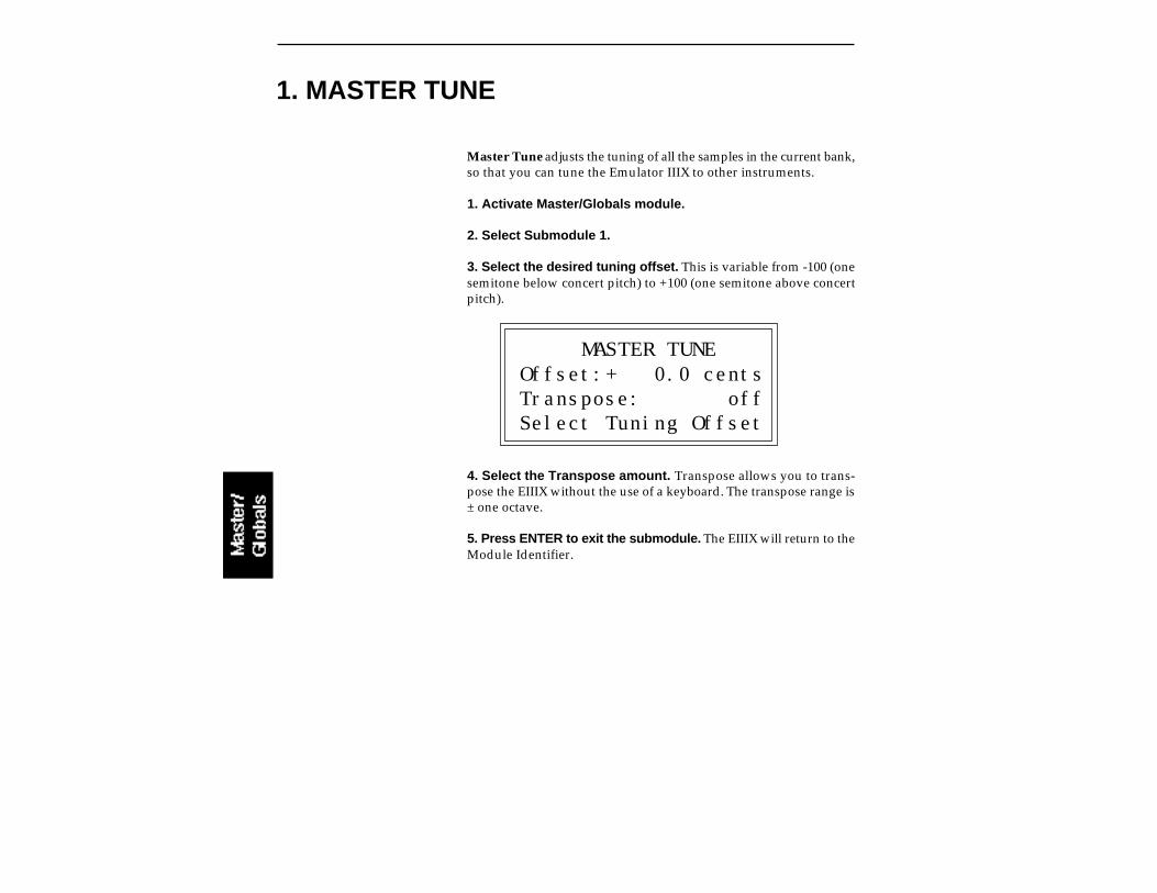
Master Tune adjusts the tuning of all the samples in the current bank,so that you can tune the Emulator IIIX to other instruments.
1. Activate Master/Globals module.
2. Select Submodule 1.
3. Select the desired tuning offset. This is variable from -100 (onesemitone below concert pitch) to +100 (one semitone above concertpitch).
MASTER TUNEOffset:+ 0.0 centsTranspose: offSelect Tuning Offset
4. Select the Transpose amount. Transpose allows you to trans-pose the EIIIX without the use of a keyboard. The transpose range is± one octave.
5. Press ENTER to exit the submodule. The EIIIX will return to theModule Identifier.
1. MASTER TUNE
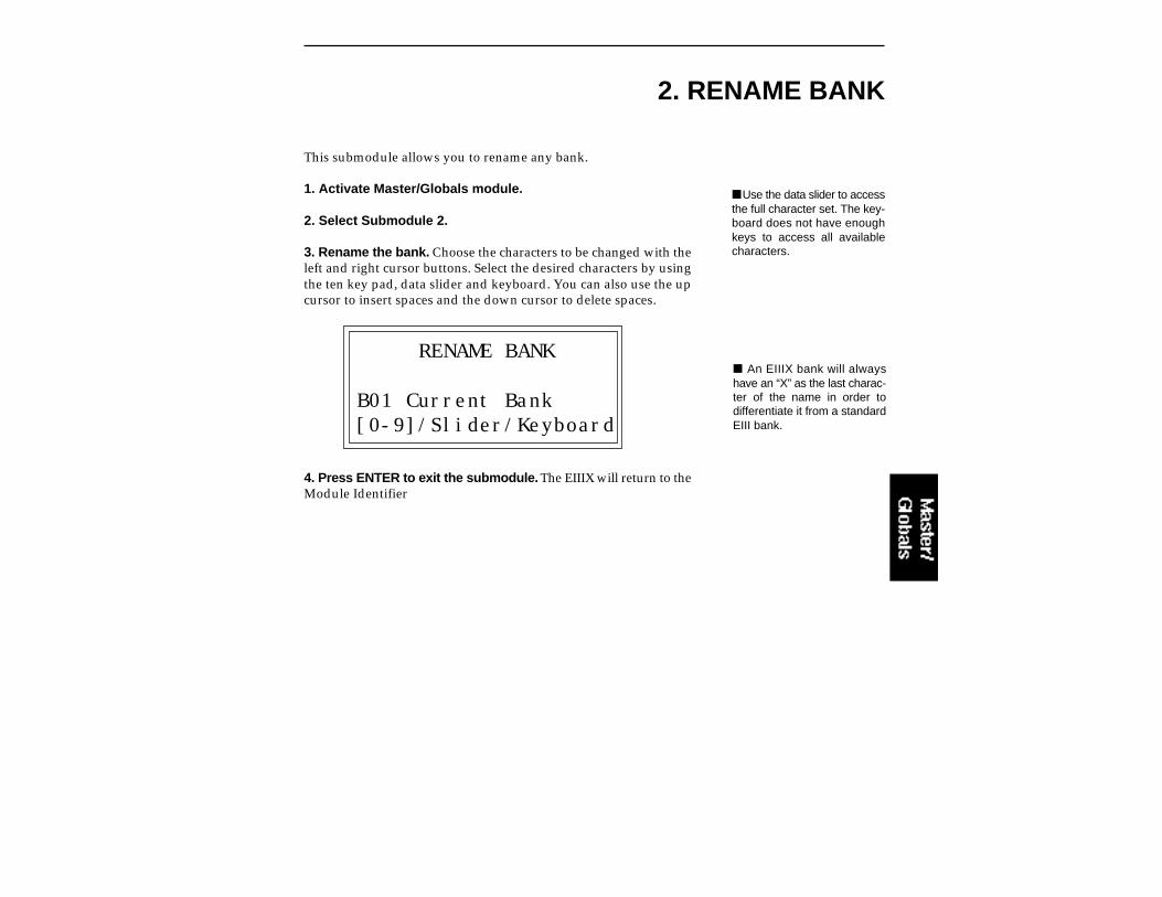
2. RENAME BANK
This submodule allows you to rename any bank.
1. Activate Master/Globals module.
2. Select Submodule 2.
3. Rename the bank. Choose the characters to be changed with theleft and right cursor buttons. Select the desired characters by usingthe ten key pad, data slider and keyboard. You can also use the upcursor to insert spaces and the down cursor to delete spaces.
RENAME BANK
B01 Current Bank[0-9]/Slider/Keyboard
4. Press ENTER to exit the submodule. The EIIIX will return to theModule Identifier
An EIIIX bank will alwayshave an “X” as the last charac-ter of the name in order todifferentiate it from a standardEIII bank.
Use the data slider to accessthe full character set. The key-board does not have enoughkeys to access all availablecharacters.
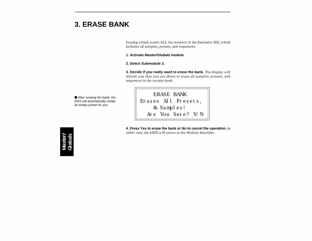
Erasing a bank erases ALL the memory in the Emulator IIIX, whichincludes all samples, presets, and sequences.
1. Activate Master/Globals module.
2. Select Submodule 3.
3. Decide if you really want to erase the bank. The display willinform you that you are about to erase all samples, presets, andsequences in the current bank.
ERASE BANKErases All Presets, & Samples! Are You Sure? Y/N
4. Press Yes to erase the bank or No to cancel the operation. Ineither case, the EIIIX will return to the Module Identifier.
3. ERASE BANK
After erasing the bank, theEIIIX will automatically createan empty preset for you.

4. DYNAMIC ALLOCATION
This function (when on) bypasses the channel assignments made inthe Channel Assignment submodule of the Dynamic Processing mod-ule, and allows all of the 32 voices to be assigned in a circular manneras needed.
1. Activate Master/Globals module.
2. Select Submodule 4.
3. Select whether dynamic allocation is on or off.
DYNAMIC ALLOCATION
Mode: off Select on/off
4. Press ENTER to exit the submodule. The EIIIX will return to theModule Identifier.

5. SAVE AS EIII BANK
This function allows you to save an EIIIX bank in the original EIIIbank format so that it can be read by an EIII (the EIII is the predecessorof the EIIIX). If the bank you are trying to save exceeds 8 Mb, or hasmore then 100 presets or 100 samples, you will not be allowed to saveas an EIII bank.
1. Activate Master/Globals module.
2. Select Submodule 6.
3. If necessary, select the drive to which the bank will be saved.The EIIIX will default to the current drive. If you want to choose adifferent drive, place the cursor under the drive number in line twoof the display, select the appropriate drive and press ENTER.
SAVE E3 BANK intoD3 Syquest SQ555
Select a Drive
4. Select the bank number to which the bank will be saved. Emptybanks will be indicated as such, along with their bank number on linethree. Or, you can overwrite an existing bank.
SAVE E3 BANK intoD3 Syquest SQ555B02 Rik 12 String Select a Bank
5. After selecting the bank number and drive, press ENTER. Thedisplay will say “Saving Bank”. After a few seconds, the bank willbe saved. The display will revert to the preset selection screen.

6. MEMORY AVAILABLE
Memory Available shows how much of each type of memory is avail-able, both as a percentage of available memory and in bytes. Forexample, if you have used up 90.0% of the available preset memory, thedisplay will show that there is 10.0% preset memory remaining.
1. Activate Master/Globals module.
2. Select Submodule 6.
3. Observe the display. Line three shows the percentage and amountof preset memory available. Line four shows the percentage and amountof sample memory available. Line four shows the number of sequencerevents available.
MEMORY AVAILABLE
Preset: 99.8% 127KSample: 100% 32.0M
4. Press ENTER to exit the submodule. The EIIIX will return to theModule Identifier.
Memory Defragment: When samples are erased or truncated, thememory is left fragmented until the bank is saved to disk. Fragmentedmemory may limit new sample size , even though you have plenty ofmemory left. This hidden function allows you to manually defragment.
1. Press the Inc/Yes button while in Memory Available.
COLLECT SAMPLE MEM
Collect Memory? Y/N
2. Press Yes to collect the samples, No to exit the submodule.
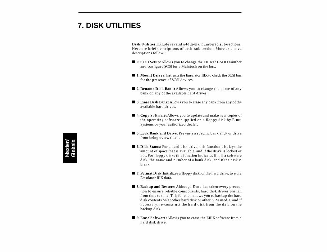
7. DISK UTILITIES
Disk Utilities Include several additional numbered sub-sections.Here are brief descriptions of each sub-section. More extensivedescriptions follow.
0. SCSI Setup: Allows you to change the EIIIX's SCSI ID numberand configure SCSI for a McIntosh on the bus.
1. Mount Drives: Instructs the Emulator IIIX to check the SCSI busfor the presence of SCSI devices.
2. Rename Disk Bank: Allows you to change the name of anybank on any of the available hard drives.
3. Erase Disk Bank: Allows you to erase any bank from any of theavailable hard drives.
4. Copy Software: Allows you to update and make new copies ofthe operating software supplied on a floppy disk by E-muSystems or your authorized dealer.
5. Lock Bank and Drive: Prevents a specific bank and/or drivefrom being overwritten.
6. Disk Status: For a hard disk drive, this function displays theamount of space that is available, and if the drive is locked ornot. For floppy disks this function indicates if it is a softwaredisk, the name and number of a bank disk, and if the disk isblank.
7. Format Disk: Initializes a floppy disk, or the hard drive, to storeEmulator IIIX data.
8. Backup and Restore: Although E-mu has taken every precau-tion to ensure reliable components, hard disk drives can failfrom time to time. This function allows you to backup the harddisk contents on another hard disk or other SCSI media, and ifnecessary, re-construct the hard disk from the data on thebackup disk.
9. Erase Software: Allows you to erase the EIIIX software from ahard disk drive.

0. SCSI SETUPThis utility allows you to change the SCSI ID number of the EIIIX itself(not it's internal hard disk) in the event that it conflicts with a deviceon the SCSI bus having the same ID number.
The SCSI interface, located as a 25-pin connector on the back panel,allows the EIIIX to communicate with external storage devices. TheEIIIX can support seven SCSI devices (including it's internal HD if ithas one). Each device on the SCSI bus has it’s own ID number so thatit can distinguish its data from data meant for other SCSI devices. If aSCSI device is added to your system which has the same ID numberas an existing device, a SCSI error would occur. To remedy thissituation, the ID number on the new device will have to be changed.Consult the operation manual of the external device for informationon changing the SCSI ID number.
The EIIIX also contains special SCSI software that allows two “master”devices (the EIIIX and a McIntosh) to coexist on the SCSI bus. If youhave a Macintosh computer connected to the EIIIX SCSI bus, the Macon SCSI bus function should be turned On.
1. Activate Master/Globals module.
2. Select 7. Disk Utilities, 0. SCSI Setup (7/0).
3. Select the new SCSI ID number.
SCSI SETUP
EIIIX SCSI ID: 5Mac on SCSI Bus: no
4. If a Macintosh is present on the SCSI bus, turn “Mac on SCSIBus” On.
5. Press ENTER to exit the submodule. The EIIIX will save yourchoices to the System and return to the Module Identifier.

1. Mount DrivesThis utility instructs the EIIIX to check the SCSI bus for the presenceof SCSI devices.
If a SCSI device has been powered up after the Emulator IIIX, it willnot appear in the list of available devices. The Mount Drives utilitytells the EIIIX to check the SCSI bus and to add any SCSI devices thatit finds to its list of available SCSI devices. Normally, if the externaldevices are powered up before the EIIIX, this will be done automati-cally.
1. Activate Master/Globals module.
2. Select 7. Disk Utilities, 1. Mount Drives (7/1).
3. The Emulator IIIX will mount the drives, then return to theModule Identifier.
2. Rename Disk BankThis function allows you to name your banks.
1. Activate Master/Globals module.
2. Select 7. Disk Utilities, 2. Rename Disk Bank (7/2).
3. Select an installed drive, then press ENTER.
RENAME DISK BANKD1 QUANTUM LP1055B01 12 String X Select a Drive
4. Select the bank to be renamed, then press ENTER.
5. Rename the bank. Choose the characters to be changed with theleft and right cursor buttons. Select the desired characters by usingthe ten key pad, data slider and keyboard. You can also use the upcursor to insert spaces and the down cursor to delete spaces.
Use the "Mount Drives" util-ity whenever an external SCSIdevice does not appear on thelist of available devices.

RENAME DISK BANKD1 QUANTUM LP1055B01 12 String X [0-9]/Slider/Kybd
5. Press ENTER to exit the submodule. The EIIIX will return to theModule Identifier.
3. Erase Disk BankWith this utility, banks can be erased from any of the available drives.
1. Activate Master/Globals module.
2. Select 7. Disk Utilities, 3. Erase Bank (7/3).
3. If you wish to select a different drive, press the up cursor. Ifnot, proceed to step 5.
4. Select the drive containing the bank to be erased, then pressENTER.
ERASE DISK BANKD1 QUANTUM LP1055B01 12 String X Select a Drive
5. Select the bank to be erased, then press ENTER.
ERASE DISK BANKD1 QUANTUM LP1055B01 12 String X Select a Bank
6. Decide if in fact you want to erase the selected bank. Thedisplay will ask if you’re sure.
7. Press Yes to erase the bank or No to cancel the operation. Ineither case, the EIIIX will return to the Module Identifier.
The display will advise you ifyou try to erase a bank or drivethat is locked. Unlock the bankand/or drive before proceed-ing.
The “X” at the end of thebank name indicates that thebank is an EIIIX bank.

4. Copy SoftwareFrom time to time, the E-mu engineers devise new operating systemsoftware intended to enhance or add new features to the EIIIX’sexisting capabilities. This software is distributed on a floppy disk.Software should be copied over to the hard disk so that the newsystem will automatically load whenever you turn on the EIIIX. Thesystem software should be resident on only one hard disk drive inyour equipment setup. If you do not install new software on the harddisk you will have to load it from the floppy disk each time youpower up the machine.
Each version of the operating system is numbered, and is indicatedwhen you select 8. Special, 6. Software Version (8/6). Copyingsoftware on to the hard disk will not change any other data likesamples, presets, and sequences. It is a good idea to keep at least twobackup copies of the system software on floppy disk.
1. Activate Master/Globals module.
2. Select 7. Disk Utilities, 4. Copy Software (7/4).
3. Select the drive containing the new software and pressENTER. Usually this will be the floppy drive. After pressing ENTER,the display will inform you that the new software is being loaded.
COPY SOFTWARE fromD0 Floppy Drive
Select a Drive
4. Select the destination drive for the new software and pressENTER. Typically, this will be the Emulator IIIX’s internal hard diskdrive. After pressing ENTER, the software will be copied and theEIIIX will return to the Module Identifier.
COPY SOFTWARE intoD0 Floppy DriveD1 Quantum LP1055 Select a Drive
If there is not enoughsample memory left to accom-modate the new software, thedisplay will ask if you want toerase the bank. Press Yes toerase the bank and continueloading software from thedrive. Press No to cancel theoperation so that you can savethe bank first, before copyingthe new software.
If the disk you are copying tois an unformatted floppy, youwill be asked if you wish toformat the disk. Press Yes toformat the floppy disk, or inserta formatted disk and press No.
If you copied new softwareto the boot drive, now is a goodtime to power the Emulator IIIXoff and on.
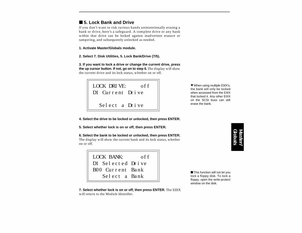
5. Lock Bank and DriveIf you don’t want to risk curious hands unintentionally erasing abank or drive, here’s a safeguard. A complete drive or any bankwithin that drive can be locked against inadvertent erasure ortampering, and subsequently unlocked as needed.
1. Activate Master/Globals module.
2. Select 7. Disk Utilities, 5. Lock Bank/Drive (7/5).
3. If you want to lock a drive or change the current drive, pressthe up cursor button. If not, go on to step 6. The display will showthe current drive and its lock status, whether on or off.
LOCK DRIVE: offD1 Current Drive
Select a Drive
4. Select the drive to be locked or unlocked, then press ENTER.
5. Select whether lock is on or off, then press ENTER.
6. Select the bank to be locked or unlocked, then press ENTER.The display will show the current bank and its lock status, whetheron or off.
LOCK BANK: offD1 Selected DriveB00 Current Bank Select a Bank
7. Select whether lock is on or off, then press ENTER. The EIIIXwill return to the Module Identifier.
This function will not let youlock a floppy disk. To lock afloppy, open the write-protectwindow on the disk.
When using multiple EIIIX's,the bank will only be lockedwhen accessed from the EIIIXthat locked it. Any other EIIIXon the SCSI buss can stillerase the bank.
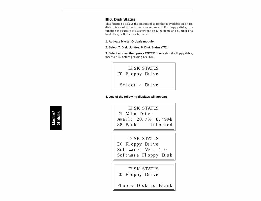
6. Disk StatusThis function displays the amount of space that is available on a harddisk drive and if the drive is locked or not. For floppy disks, thisfunction indicates if it is a software disk, the name and number of abank disk, or if the disk is blank.
1. Activate Master/Globals module.
2. Select 7. Disk Utilities, 6. Disk Status (7/6).
3. Select a drive, then press ENTER. If selecting the floppy drive,insert a disk before pressing ENTER.
DISK STATUSD0 Floppy Drive
Select a Drive
4. One of the following displays will appear:
DISK STATUSD1 Main DriveAvail: 20.7% 8.49Mb88 Banks Unlocked
DISK STATUSD0 Floppy DriveSoftware: Ver. 1.0Software Floppy Disk
DISK STATUSD0 Floppy Drive
Floppy Disk is Blank

5. To select another disk, press ENTER and return to step 3.
6. Press the Master/Globals button to exit the submodule. TheEIIIX will return to the Module Identifier.
7. Format DiskBefore a new floppy disk or hard disk can record or store any data, itfirst must be told how to record this data. This is called formatting. Thefloppy disk formatting procedure should be run on any new disk, oron recycled disks previously used with other systems (such as homecomputers), since these will not be formatted correctly for the Emula-tor IIIX.
1. Activate Master/Globals module.
2. Select 7. Disk Utilities, 7. Format Disk (7/7).
3. Select the drive to be formatted and press ENTER. The EIIIX willdefault to the floppy drive.
FORMAT DISKD0 Floppy Drive
Select a Drive
4. Consider the implications of your action. Formatting a floppy orhard disk erases all information on that disk completely. The displaywill inquire if in fact you want to do this.
5. Press Yes to continue the formatting procedure or No to cancelthe operation and return to the Module Identifier.
6. If in step 3 you selected the floppy drive, insert a floppy disk,and press ENTER. Formatting takes about 20 seconds.
7. After formatting a floppy disk, format another, if desired. Thedisplay will ask if you want to format another floppy. To do this, pressYes, remove the current disk, insert a new disk, and press ENTER.Otherwise, press No to cancel the operation and return to the ModuleIdentifier.
Formatting a floppy disk willnot erase the bank currently inmemory.

FORMATTING HARD DISKSThis works exactly like formatting a floppy disk except when thedisplay asks you to "Select a Drive", you should select the hard diskinstead of the floppy. If the hard disk is not listed, use Disk Utilities1, to Mount Drive. The hard disk drive should now be listed.Formatting a hard drive takes several minutes, depending on the sizeof the HD.
R/W OPTICAL DISKSRead/Write Optical disks are formatted in the same way as a harddisk. Use optical disk cartridges with 512 bytes/sector rather thanthe 1024 byte/sector type. New optical disk cartridges usually comewith the "low level" formatting already in place. If so, the disk willformat normally. If this low level formatting has not been performed,the EIIIX will interrupt the formatting process and show a "SCSIHardware Error". If this happens, follow the procedure for LowLevel formatting on the next page, then format the disk in the normalway.
Note: Optical disks always verify the data as it is written and so donot require the long verify process that occurs after formatting hasbeen completed. You can save hours of time by ejecting the cartridgeand re-booting the system after the "VERIFYING FORMAT" mes-sage appears in the EIIIX display (about 10 seconds).
HARD DISK INTERLEAVEThe Emulator Three contains an internal list of recognized hard diskdrives. The list contains parameter information designed to optimizethe interface between the EIIIX and the drive. The following harddisk drive brands are currently listed:
Miniscribe 2:1 interleave Rodime 2:1 interleave CDC 1:1 interleave Syquest 1:1 interleave Qume 4:1 interleave Quantum 1:1 interleave
Other hard disk brands will probably also work. If in doubt, the bestidea is to try out the drive with the EIIIX before you buy it. If yourbrand of hard drive is not listed but works with the EIIIX, you maybe able to optimize its performance even further.
8. There is a hidden menu when the display asks: "Are YouSure?".
The recommended type ofR/W Optical drive for theEIIIX uses the Sony typecartridge. Brand namesinclude Sony, Pinnacle, PLI,and Alphatronics to name afew.
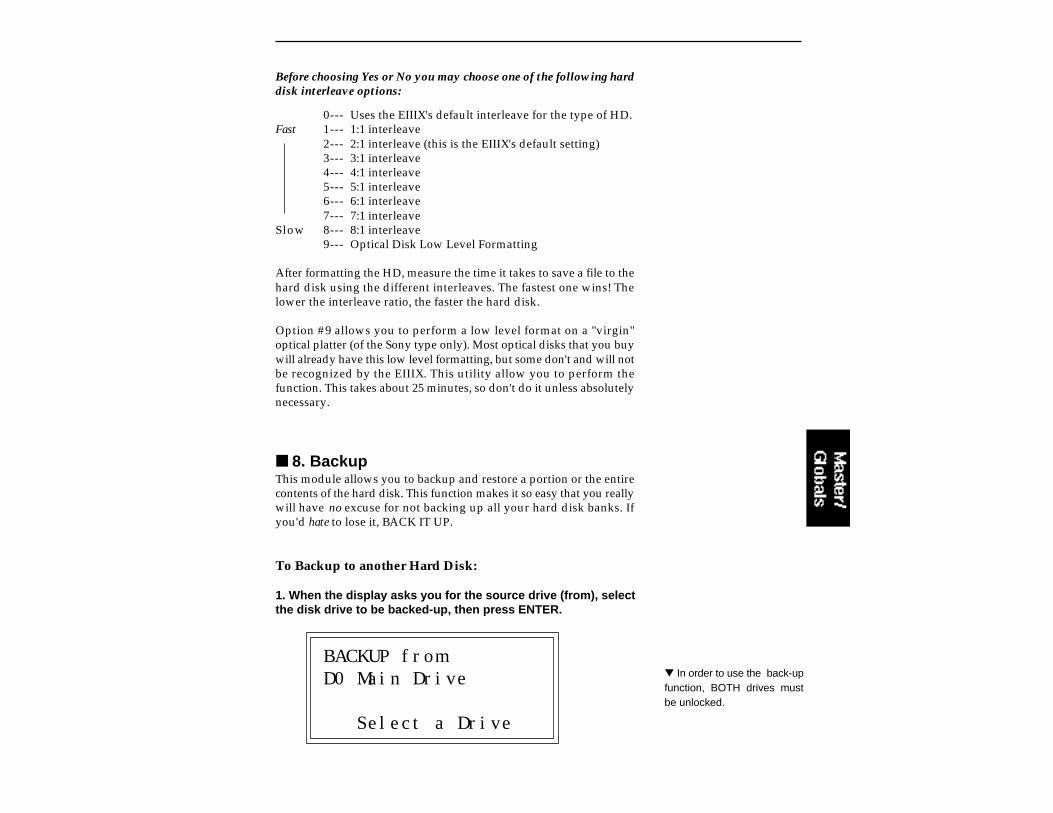
Before choosing Yes or No you may choose one of the following harddisk interleave options:
0--- Uses the EIIIX's default interleave for the type of HD.Fast 1--- 1:1 interleave
2--- 2:1 interleave (this is the EIIIX's default setting)3--- 3:1 interleave4--- 4:1 interleave5--- 5:1 interleave6--- 6:1 interleave7--- 7:1 interleave
Slow 8--- 8:1 interleave9--- Optical Disk Low Level Formatting
After formatting the HD, measure the time it takes to save a file to thehard disk using the different interleaves. The fastest one wins! Thelower the interleave ratio, the faster the hard disk.
Option #9 allows you to perform a low level format on a "virgin"optical platter (of the Sony type only). Most optical disks that you buywill already have this low level formatting, but some don't and will notbe recognized by the EIIIX. This utility allow you to perform thefunction. This takes about 25 minutes, so don't do it unless absolutelynecessary.
8. BackupThis module allows you to backup and restore a portion or the entirecontents of the hard disk. This function makes it so easy that you reallywill have no excuse for not backing up all your hard disk banks. Ifyou'd hate to lose it, BACK IT UP.
To Backup to another Hard Disk:
1. When the display asks you for the source drive (from), selectthe disk drive to be backed-up, then press ENTER.
BACKUP fromD0 Main Drive
Select a Drive
In order to use the back-upfunction, BOTH drives mustbe unlocked.
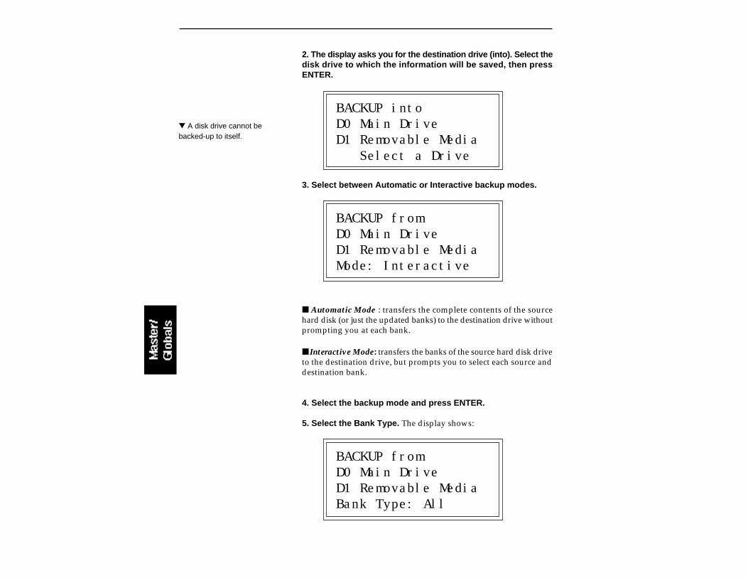
2. The display asks you for the destination drive (into). Select thedisk drive to which the information will be saved, then pressENTER.
BACKUP intoD0 Main DriveD1 Removable Media Select a Drive
3. Select between Automatic or Interactive backup modes.
BACKUP fromD0 Main DriveD1 Removable MediaMode: Interactive
Automatic Mode : transfers the complete contents of the sourcehard disk (or just the updated banks) to the destination drive withoutprompting you at each bank.
Interactive Mode: transfers the banks of the source hard disk driveto the destination drive, but prompts you to select each source anddestination bank.
4. Select the backup mode and press ENTER.
5. Select the Bank Type. The display shows:
BACKUP fromD0 Main DriveD1 Removable MediaBank Type: All
A disk drive cannot bebacked-up to itself.
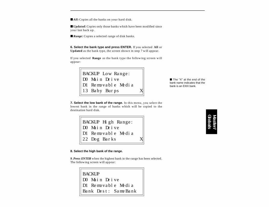
All: Copies all the banks on your hard disk.
Updated: Copies only those banks which have been modified sinceyour last back up.
Range: Copies a selected range of disk banks.
6. Select the bank type and press ENTER. If you selected All orUpdated as the bank type, the screen shown in step 7 will appear.
If you selected Range as the bank type the following screen willappear:
BACKUP Low Range:D0 Main DriveD1 Removable Media13 Baby Burps X
7. Select the low bank of the range. In this menu, you select thelowest bank in the range of banks which will be copied to thedestination hard disk.
BACKUP High Range:D0 Main DriveD1 Removable Media22 Dog Barks X
8. Select the high bank of the range.
9. Press ENTER when the highest bank in the range has been selected.The following screen will appear:
BACKUPD0 Main DriveD1 Removable MediaBank Dest: SameBank
The “X” at the end of thebank name indicates that thebank is an EIIIX bank.

Same Bank: Copies the banks into the same numbered banklocations on the destination disk.
Empty Bank: Copies the banks into the lowest consecutive emptybank locations on the destination disk.
10. Select the bank destination and press ENTER. The displaywill inquire if you are sure. Press Yes if you are, and backup willproceed. Press No to cancel the operation and return to the ModuleIdentifier.
During the Backup procedure, the display will show the banks beingcopied.
To Restore:To restore your backed-up disk, simply reverse the source anddestination drives following the directions for backup.
9. Erase SoftwareWith this function, software can be erased from any of the hard diskdrives. If the EIIIX operating system software has been copied ontomore than one hard disk, you might want to erase it so that the EIIIXwill boot from a particular drive. This utility allows you to do it.
1. Activate Master/Globals module.
2. Select 7. Disk Utilities, 9. Erase Software (7/9).
3. Select the drive containing the software to be erased, thenpress ENTER.
ERASE SOFTWARED0 Main Drive
Select a Drive
4. Decide if you really want to erase the software. The display willask if you really want to do this.
5. Press Yes to erase the software or No to cancel the operation.In either case, the EIIIX will return to the Module Identifier.
This section contains several additional numbered functions. Here areshort descriptions of each sub-module. More extensive descriptionsfollow.
1. Audition Key: Allows the Emulator IIIX to be played without akeyboard. This function sets the key that will be played when theAudition button on the front panel is pressed.
2. Recalibrate: Allows you to recalibrate the action of the data andvolume sliders on the front panel.
3. Contrast: This function allows you to adjust the contrast of thefront panel LCD .
4. Headroom: Allows you to adjust the amount of available head-room of the EIII's D/A converters.
5. Main Output Format: This function adjusts the EIIIX for optimumperformance when using either the main analog outputs or the digitalI/O.
6. Software Version: States the current version of the operatingsystem software.
7. Disable Channels: If an Emulator IIIX output channel fails, youcan locate and disable it with this function.
8. Volume Curve: Allows you to select 1 of 8 volume responsecurves. These curves are applied to any controller that affects the finalvolume, such as volume envelope, MIDI volume, etc.
To Access Any of the Special Functions:
1. Activate Master/Globals.
2. Select Submodule 8 and press ENTER.
3. Select the desired function in Submodule 8 andpress ENTER.
8. SPECIAL

1. Audition KeyThis screen allows you to set the key that will be played when theAudition button on the front panel is pressed. The audition buttonallows you to audition sounds from the EIIIX with having a MIDIkeyboard connected.
1. Activate Master/Globals module.
2. Select 8. Special, 1. Audition Key (8/1).
3. Select the pitch to be auditioned when the audition button ispressed.
AUDITION KEY
Pitch: C3 Select a Pitch
5. Press ENTER to exit the submodule. The EIIIX will return to theModule Identifier.
2. RecalibrateWith this function you can set minimum and maximum values forthe data and volume sliders. If you feel that the sliders are notworking correctly, it may be time to recalibrate.
1. Activate Master/Globals module.
2. Select 8. Special, 2. Recalibrate (8/2).
3. Select the controller to be recalibrated using the inc/decbuttons, then press ENTER. Moving the slider shows the currentrange of movement. The values should range from 000-255.
RECALIBRATE1 Data SliderValue: 255 Select a Controller
The Audition button allowsyou to preview samplesdirectly from the hard diskwhen you are in the “LoadSample” screen.
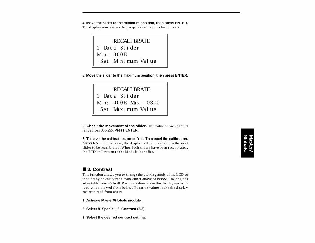
4. Move the slider to the minimum position, then press ENTER.The display now shows the pre-processed values for the slider.
RECALIBRATE1 Data SliderMin: 000E Set Minimum Value
5. Move the slider to the maximum position, then press ENTER.
RECALIBRATE1 Data SliderMin: 000E Max: 0302 Set Maximum Value
6. Check the movement of the slider. The value shown shouldrange from 000-255. Press ENTER.
7. To save the calibration, press Yes. To cancel the calibration,press No. In either case, the display will jump ahead to the nextslider to be recalibrated. When both sliders have been recalibrated,the EIIIX will return to the Module Identifier.
3. ContrastThis function allows you to change the viewing angle of the LCD sothat it may be easily read from either above or below. The angle isadjustable from +7 to -8. Positive values make the display easier toread when viewed from below. Negative values make the displayeasier to read from above.
1. Activate Master/Globals module.
2. Select 8. Special , 3. Contrast (8/3)
3. Select the desired contrast setting.

CONTRAST
Contrast: -2 Select Contrast
4. Press ENTER to exit the submodule. The EIIIX will return to theModule Identifier.
4. HeadroomHeadroom is the amount of dynamic range remaining before clip-ping will occur. Sampling instruments are quite different from a CDplayer, since a sampler plays multiple channels at once. Each channelboosts the headroom requirement by 3 dB. The amount of headroomon the EIIIX is adjustable from 0 dB to 15 dB in 1 dB increments (withthe front panel volume control set to maximum). A headroom settingof 0 dB for example, will provide the hottest output level, (and thehighest signal to noise ratio) but may cause “clipping” if too manynotes are played at once. The default headroom setting is 10 dB,which maintains an excellent signal to noise ratio while keeping areasonable amount of headroom in reserve. If you hear clipping fromthe EIIIX, raise the amount of headroom. The headroom setting isretained when power is switched off.
1. Activate Master/Globals module.
2. Select 8. Special , 4. Headroom (8/4)
3. Select the desired amount of headroom. The amount of remain-ing headroom is variable from 0 dB to 15 dB in 1 dB increments.
HEADROOM
Headroom: 10dB Select Headroom
4. Press ENTER to exit the submodule. The EIIIX will return to theModule Identifier.
The headroom adjustmentalso controls the level on thedigital audio output.

Each channel played adds +3dB to the output of the EIIIX. The headroomcontrol allows you to add more channels without clipping.
The VCF can boost the signal by up to 40 dB with high amounts of resonance.

5. Main Output FormatThe EIIIX is equipped with a digital audio output for interfacing withother digital audio equipment. Both the S/PDIF (consumer) and theAES/EBU (professional) format are supported. The digital audiointerface carries two channels of audio information which mirrorsthe audio at the main outputs. Both audio and digital I/O data arealways active. This function optimizes the EIIIX's output for what-ever format is being used.
1. Activate Master/Globals module.
2. Select 8. Special , 5. Main Output Format (8/5)
3. Select the desired output format. Use the data slider or inc/decbuttons to select between analog, AES consumer digital or AESprofessional digital output.
OUTPUT FORMAT
Format: AES proSelect Output Format
4. Press ENTER to exit the submodule. The EIIIX will return to theModule Identifier.
6. Software Version
1. Activate Master/Globals module.
2. Select 8. Special , 6. Software Version (8/6)
SOFTWARE VERSION Emulator III©1992 E-mu Systems Version 1.0
When connecting the digitaloutput to consumer audiogear, it may be necessary touse an adapter cable. Thisadapter should be con-structed using video-gradecoaxial cable.
Always use high-quality,low-capacitance, three-wirecable for the AES/EBU inter-face to insure data integrity.
The headroom adjustment ,the master volume control,and VCA level all control thelevel on the digital audio out-put. These controls can beadjusted when transferringdigital audio to optimize thesignal level.
For a single channel output,the maximum output level ofthe EIIIX will be -6 dB.

3. The display shows the disk software version.
4. Press ENTER to exit the submodule. The EIIIX will return to theModule Identifier.
7. Disable ChannelsIn rare situations, a channel can fail. It may go quietly, or it mayproduce unwanted sounds. In either case, the individual outputchannel can be temporarily turned off so as not to cause problems untilit can be repaired.
1. Activate Master/Globals module.
2. Select 8. Special, 7. Disable Channels (8/7).
3. Use the left/right cursor buttons to place the cursor under thechannel to be disabled. The channel number is shown on line 4 of thedisplay. As notes are played, the display will show small bar graphsof the VCA envelopes for each of the 32 channels, making it easier todetermine which channel is bad.
DISABLE CHANNELS---x ---- ---- -------- ---- ---- ---- Channel=01
4. When the cursor is under the channel to be edited, press Off todisable, or On to enable. If the channel is disabled, it will be indicatedby a small “X” in that location. There are two rows of 16 channelsshown in the display.
5. Press ENTER to exit the submodule. The EIIIX will return to theModule Identifier.

8. Volume CurveThe Emulator IIIX contains 8 different volume response curves.These curves should not be confused with MIDI velocity curves. Thecurves are only applied to controls which affect the final output VCA.They were originally designed to match the EIIIX's response to thatof the original EIII, but a few more were added for variety. Choose thecurve that has the smoothest volume response with your particularsequencer or controller.
1. Activate Master/Globals module.
2. Select 8. Special, 8. Volume Curve (8/8).
3. Select the desired volume curve. Refer to the diagrams belowand on the next page.
VOLUME CURVE
Curve: 2 Select Curve
4. Press ENTER to exit the submodule. The EIIIX will return youto the Module Identifier.
VOLUME CURVES
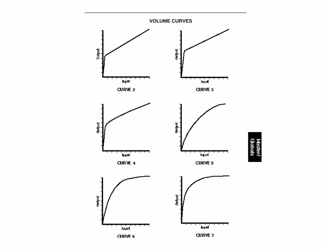
VOLUME CURVES
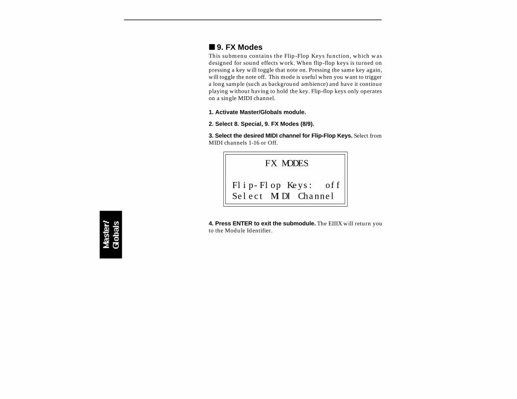
9. FX ModesThis submenu contains the Flip-Flop Keys function, which wasdesigned for sound effects work. When flip-flop keys is turned onpressing a key will toggle that note on. Pressing the same key again,will toggle the note off. This mode is useful when you want to triggera long sample (such as background ambience) and have it continueplaying without having to hold the key. Flip-flop keys only operateson a single MIDI channel.
1. Activate Master/Globals module.
2. Select 8. Special, 9. FX Modes (8/9).
3. Select the desired MIDI channel for Flip-Flop Keys. Select fromMIDI channels 1-16 or Off.
FX MODES
Flip-Flop Keys: offSelect MIDI Channel
4. Press ENTER to exit the submodule. The EIIIX will return youto the Module Identifier.

9. MIDI
This section contains several additional numbered functions. TheMIDI global functions act on the entire EIIIX. MIDI functions thatoperate on specific presets are located in the Preset Definition menu.Here are short descriptions of each sub-module. More extensivedescriptions follow.
1. MIDI Mix: Allows you to monitor and change the volume andpan settings of all 16 MIDI channels at once. It also lets you overridethe submix output settings made in the zone and assign themaccording to MIDI channel.
2. MIDI Globals: MIDI global commands override the MIDIsettings programmed for each preset in the Preset Definition moduleand return us to a simpler time when MIDI settings affected allpresets.
3. MIDI Load Bank: This feature allows a MIDI command to loadbanks from a hard disk.
4. MIDI Volume Pedal Global Override: Allows an external MIDIcontroller (pedal) to function like a master volume pedal.
5. MIDI Volume/Pan: This function automatically routes the MIDIcontrollers 7 and 10 to volume and pan. It also disables controllers 7and 10 in the Preset Definition MIDI submodule.
6. Multimode Enable: Selects whether or not Multimode On/Offis set globally or dependent on each bank.
To Access Any of the MIDI Functions:
1. Activate Master/Globals.
2. Select Submodule 9 and press ENTER.
3. Select the desired function in Submodule 9 andpress ENTER.

1. MIDI MixThe MIDI Mix screen is very useful in that it allows you to easily finetune the volume and pan of each preset. In addition, it allows you tooverride the output channel setting programmed in the DynamicProcessing module and route each MIDI channel to the output of yourchoice. These volume and pan settings can also be accessed from themultimode screen, but the MIDI Mix may be more convenient formixdown, since the volume and pan settings for all channels arevisible. Any volume and pan changes made over MIDI will be re-flected in the screen. (Volume = MIDI continuous controller channel#7, Pan = MIDI continuous controller channel #10)
1. Activate Master/Globals module.
2. Select Submodule 4.
3. Select a MIDI channel. Use the left-right cursor buttons to scrollthrough the MIDI channels. Each time you press the cursor button, thecursor moves to the next channel's bar graph volume display in linetwo. The top line of the EIIIX display shows the MIDI channel and adecimal readout of the volume setting for that channel. Use the dataslider or inc/dec buttons to change the volume levels.
MIX C=01 Volume=127
zzzz zzzz zzzz zzzz
4. Move the cursor down to line three. The volume display on lineone now changes to display the pan setting for the currently selectedMIDI channel. Pan adds to the pan setting made in the dynamicprocessing zone it is NOT an absolute pan setting. Use the left-rightcursor buttons to scroll through the MIDI channels.
MIX C=01 Pan∆=+00
zzzz zzzz zzzz zzzz
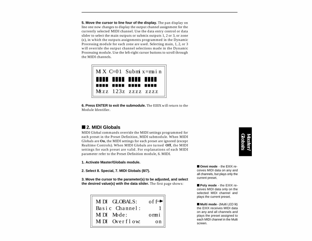
5. Move the cursor to line four of the display. The pan display online one now changes to display the output channel assignment for thecurrently selected MIDI channel. Use the data entry control or dataslider to select the main outputs or submix outputs 1, 2 or 3, or zone(z), in which the outputs assignments programmed in the DynamicProcessing module for each zone are used. Selecting main, 1, 2, or 3will override the output channel selections made in the DynamicProcessing module. Use the left-right cursor buttons to scroll throughthe MIDI channels.
MIX C=01 Submix=main
Mzzz 123z zzzz zzzz
6. Press ENTER to exit the submodule. The EIIIX will return to theModule Identifier.
2. MIDI GlobalsMIDI Global commands override the MIDI settings programmed foreach preset in the Preset Definition, MIDI submodule. When MIDIGlobals are On, the MIDI settings for each preset are ignored (exceptRealtime Controls). When MIDI Globals are turned Off, the MIDIsettings for each preset are valid. For explanations of each MIDIparameter refer to the Preset Definition module, 6. MIDI.
1. Activate Master/Globals module.
2. Select 8. Special, 7. MIDI Globals (8/7).
3. Move the cursor to the parameter(s) to be adjusted, and selectthe desired value(s) with the data slider. The first page shows:
MIDI GLOBALS: offBasic Channel: 1MIDI Mode: omniMIDI Overflow: on
Omni mode - the EIIIX re-ceives MIDI data on any andall channels, but plays only thecurrent preset.
Poly mode - the EIIIX re-ceives MIDI data only on theselected MIDI channel andplays the current preset.
Multi mode - (Multi LED lit)the EIIIX receives MIDI dataon any and all channels andplays the preset assigned toeach MIDI channel in the Multiscreen.

4. Select page two by pressing the right cursor button. The secondpage shows:
MIDI GLOBALS
Send Preset Chg: onRecv Preset Chg: on
5. Press ENTER to exit the submodule. The changes will be storedand the EIIIX will return to the Module Identifier.
3. MIDI Load BankThis feature allows a MIDI command to load banks from the hard disk.The “Magic Preset” is a preset number which tells the EIIIX that thenext preset change command that it receives over MIDI is the banknumber to be loaded. Therefore, to load a hard disk bank over MIDI,two program change commands must be sent, the Magic Preset andthe bank number. For example, if the Magic Preset is set at “P85”, andthe EIIIX receives a preset change command of 85 followed by a presetchange command of 11, the EIIIX will load bank 11 from the hard disk.If multiple SCSI drives are connected, the EIIIX will load from thedrive most recently accessed. The Magic Preset is user definable andcan be turned off or set to any preset number from 0 to 127. MIDI LoadBank always works, regardless of MIDI Global or MIDI submodulesettings.
1. Activate Master/Globals module.
2. Select 9. MIDI, 3. MIDI Load Bank (9/3).
MIDI LOAD BANK
Magic Preset:Pxx Off
3. Select the Magic Preset or Off to disable MIDI Load Bank.

4. Press ENTER to exit the submodule. The changes will be storedand the EIIIX will return to the Module Identifier.
4. MIDI Volume PedalThis command overrides any footpedal assignments made in theControllers Enable submodule and forces the footpedal to become avolume pedal (emulating the front panel volume slider). Volume PedalGlobal Override can be turned On or Off (default is Off). This settingis stored as part of the System Software and will remain in its settingafter the EIIIX is powered down and re-booted.
1. Activate Master/Globals module.
2. Select 9. MIDI, 4. Volume Pedal (9/4)
VOLUME PEDAL
Global Override: off
3. Select whether volume pedal global override is on or off.
4. Press ENTER to exit the submodule. The changes will be storedand the EIIIX will return to the Module Identifier.
5. MIDI Volume/PanWhen this function is turned On, the MIDI continuous controllers 7and 10 will be routed to volume and pan whenever the EIIIX ismultimode. (Volume and Pan are the standard functions of these twocontroller numbers.) Whenever the EIIIX is in multimode, MIDI con-trollers 7 and 10 control volume and pan and their assignments in thePreset Definition submodule will be ignored. When not in multi-mode, MIDI controllers 7 and 10 function as programmed in thePreset Definition submodule.
When MIDI Volume/Pan is turned Off, volume and pan must beprogrammed for each preset in the Preset Definition MIDIsubmodule.
The “Pedal” can be pro-grammed to any MIDI continu-ous controller number in thePreset Definition, MIDIsubmodule.
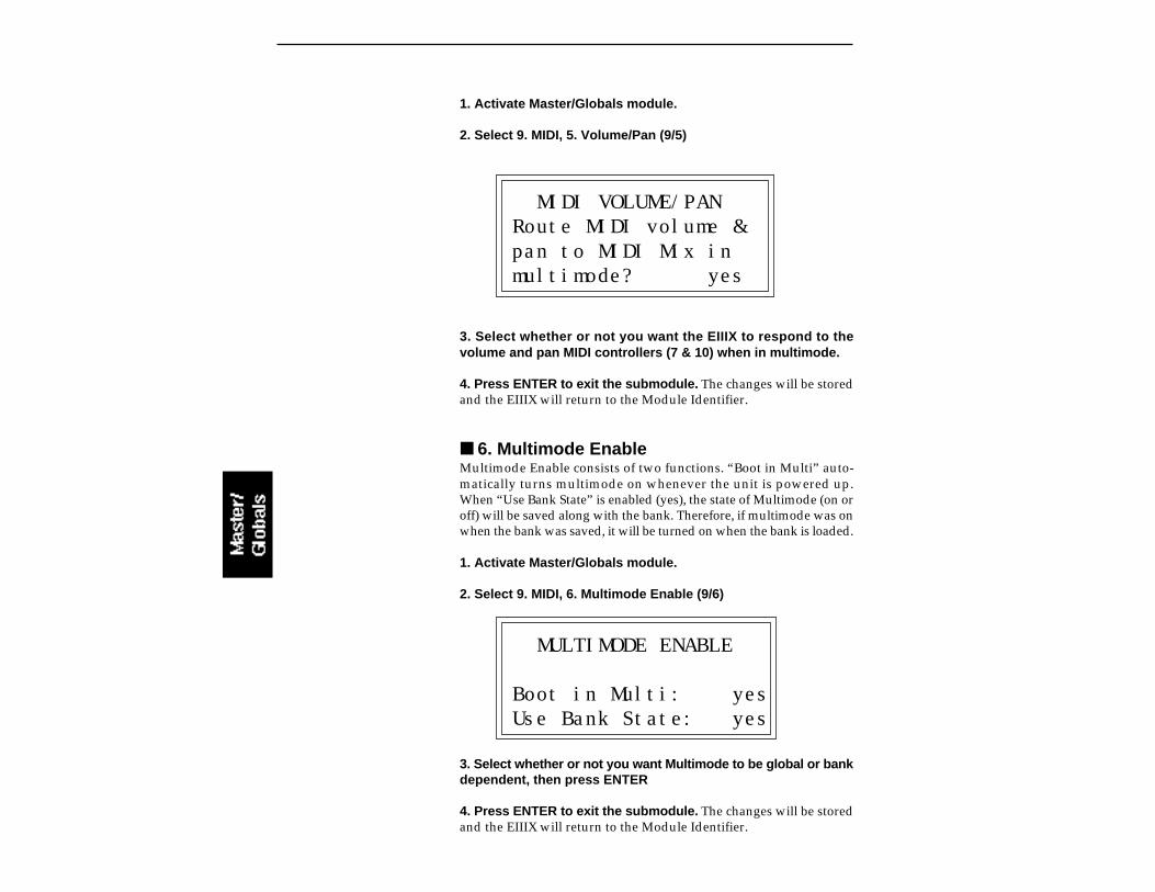
1. Activate Master/Globals module.
2. Select 9. MIDI, 5. Volume/Pan (9/5)
MIDI VOLUME/PANRoute MIDI volume &pan to MIDI Mix inmultimode? yes
3. Select whether or not you want the EIIIX to respond to thevolume and pan MIDI controllers (7 & 10) when in multimode.
4. Press ENTER to exit the submodule. The changes will be storedand the EIIIX will return to the Module Identifier.
6. Multimode EnableMultimode Enable consists of two functions. “Boot in Multi” auto-matically turns multimode on whenever the unit is powered up.When “Use Bank State” is enabled (yes), the state of Multimode (on oroff) will be saved along with the bank. Therefore, if multimode was onwhen the bank was saved, it will be turned on when the bank is loaded.
1. Activate Master/Globals module.
2. Select 9. MIDI, 6. Multimode Enable (9/6)
MULTIMODE ENABLE
Boot in Multi: yesUse Bank State: yes
3. Select whether or not you want Multimode to be global or bankdependent, then press ENTER
4. Press ENTER to exit the submodule. The changes will be storedand the EIIIX will return to the Module Identifier.

0. IMPORTThis section contains the import utilities which are used to load andconvert sound files from other equipment.
0. Akai Import: Allows the Emulator IIIX to read and convertprograms and samples from the Akai S1000 and S1100 samplers.
1. Emax II Import: Allows the Emulator IIIX to read and convertpresets and samples from the Emax II sampler.
To Access Any of the Import Functions:
1. Activate Master/Globals
2. Select Submodule 0 and press ENTER.
3. Select the desired function in Submodule 0and press ENTER.
0. Akai ImportThe Akai Import function allows you to import Programs, Samples orentire Volumes from the Akai S1000 (and S1100) samplers and convertthem into an EIIIX bank. Data is imported into the EIIIX, from an Akaiformatted SCSI device. Load time varies and may be either slightlylonger or even shorter than the Akai in many cases. There are a fewfundamental differences between the Akai samplers and the EIIIX.For this reason a number of the Akai program parameters are ignoredduring the conversion process. In most cases, however, the convertedprograms and samples should sound and behave very similarly to theoriginals.
Connect the EIIIX to an Akai or Emax II formatted SCSI device.
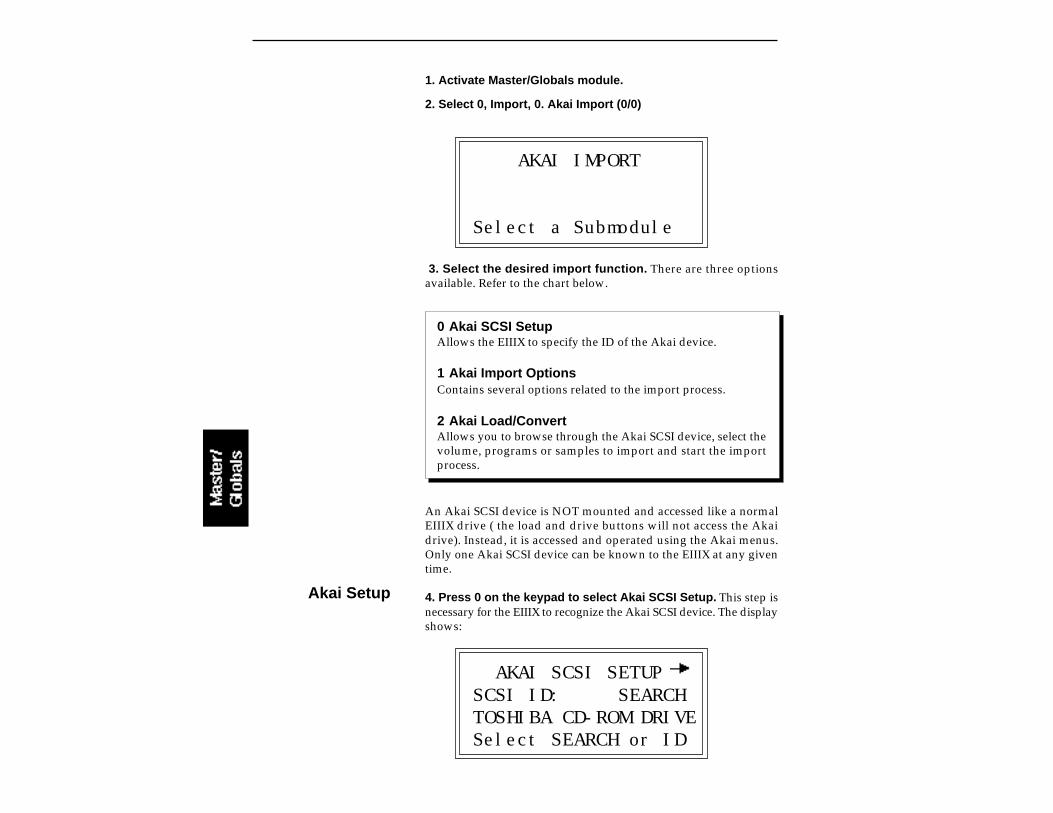
Akai Setup
1. Activate Master/Globals module.
2. Select 0, Import, 0. Akai Import (0/0)
AKAI IMPORT
Select a Submodule
3. Select the desired import function. There are three optionsavailable. Refer to the chart below.
0 Akai SCSI SetupAllows the EIIIX to specify the ID of the Akai device.
1 Akai Import OptionsContains several options related to the import process.
2 Akai Load/ConvertAllows you to browse through the Akai SCSI device, select thevolume, programs or samples to import and start the importprocess.
An Akai SCSI device is NOT mounted and accessed like a normalEIIIX drive ( the load and drive buttons will not access the Akaidrive). Instead, it is accessed and operated using the Akai menus.Only one Akai SCSI device can be known to the EIIIX at any giventime.
4. Press 0 on the keypad to select Akai SCSI Setup. This step isnecessary for the EIIIX to recognize the Akai SCSI device. The displayshows:
AKAI SCSI SETUPSCSI ID: SEARCHTOSHIBA CD-ROM DRIVESelect SEARCH or ID

The setup screen is used to select the SCSI ID of the attached Akai SCSIdevice. The SCSI ID may be selected by using the inc/dec buttons, orby typing the digit (1-7) directly using the EIIIX keypad. The defaultchoice, “Search” instructs the EIIIX to search for the first Akai devicein the SCSI chain. Normally you will use “Search” unless you want toselect a specific Akai device out of several on the SCSI bus. PressENTER, to confirm your choice and return to the option select screen.
WARNING: If you have an Akai S1000 or S1100 connected to theSCSI bus, you MUST enter the SCSI ID number of the Sampler (not theHD). Failure to do so will cause the system to crash. Press the rightcursor button for the next screen, then select the ID number of theS1000 or S1100. This ID number is remembered on power down. PressENTER, to confirm your choice and return to the option select screen.
5. Press 1 to select the Import Options screen. The followingscreen will appear. Press ENTER when you have selected yourchoices.
AKAI IMPORT OPTIONSAdjust loops: onFull placement: onCombine -L/-R: off
Adjust LoopsSample looping is implemented differently on the EIIIX and the Akai.Because of this difference, certain sample loops may “tick” slightly orappear out of tune after being transferred from the Akai. This functionwill automatically repair any incorrect sample loops after beingtransferred. Be advised that the transfer may take slightly longer (upto 15% more time) with Adjust Loops turned On.
Full PlacementThe Akai files may have samples placed on multiple layers in aprogram. The EIIIX only allows a primary and secondary layer in apreset. Turning the Full Placement function On instructs the EIIIX tocreate “Linked” EIIIX presets if an Akai preset has more than 2 layers.Velocity crossfade assignments for these links will be ignored. Anylinked presets will be placed after the main presets in the preset list.
If Full Placement is set to Off, the first two samples assigned to a keywill be placed in the primary and secondary positions for the key, andany subsequent samples assigned to the key will be ignored.
Drive 0 cannot be usedsince the EIIIX uses thisnumber for the floppy disk.
Akai ImportOptions
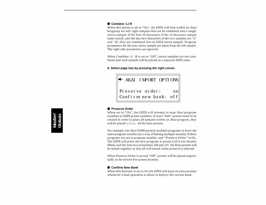
Combine -L/-RWhen this option is set to “On”, the EIIIX will look within an Akaikeygroup for left/right samples that can be combined into a singlestereo sample. If the first 10 characters of the 12 character samplename match, and the last two characters of the two samples are ‘-L’and ‘-R’, they are combined into an EIIIX stereo sample. Programparameters for the new stereo sample are taken from the left sample.The right side parameters are ignored.
When Combine -L/-R is set to “Off”, stereo samples are not com-bined and each sample will be placed in a separate EIIIX zone.
6. Select page two by pressing the right cursor.
AKAI IMPORT OPTIONS
Preserve order: onConfirm new bank: off
Preserve OrderWhen set to “On”, the EIIIX will attempt to map Akai programnumbers to EIIIX preset numbers. If extra “link” presets need to becreated in order to place all samples within an Akai program, theywill be placed after all the base presets.
For example, the Akai S1000 permits multiple programs to have thesame program number (as a way of linking multiple sounds). If threeprograms are set to program number, and “Preserve Order” is On,The EIIIX will place the first program at preset 0 (if it not alreadyfilled), and the next two at locations 126 and 127. All three presets willbe linked together so that all will sound when preset 0 is selected.
When Preserve Order is turned “Off”, presets will be placed sequen-tially in the lowest free preset location.
Confirm New BankWhen this function is set to On the EIIIX will issue an extra promptwhenever a load operation is about to destroy the current bank.
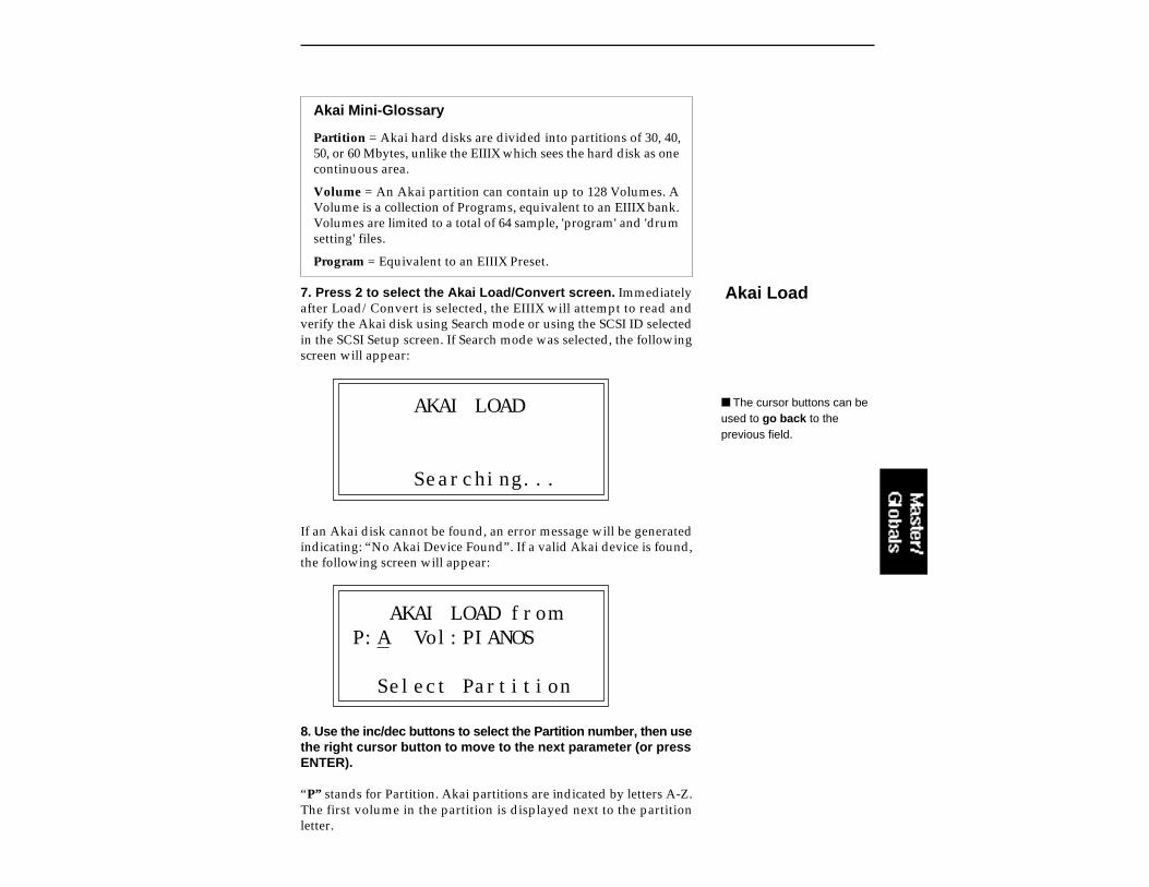
Akai Mini-Glossary
Partition = Akai hard disks are divided into partitions of 30, 40,50, or 60 Mbytes, unlike the EIIIX which sees the hard disk as onecontinuous area.
Volume = An Akai partition can contain up to 128 Volumes. AVolume is a collection of Programs, equivalent to an EIIIX bank.Volumes are limited to a total of 64 sample, 'program' and 'drumsetting' files.
Program = Equivalent to an EIIIX Preset.
7. Press 2 to select the Akai Load/Convert screen. Immediatelyafter Load/Convert is selected, the EIIIX will attempt to read andverify the Akai disk using Search mode or using the SCSI ID selectedin the SCSI Setup screen. If Search mode was selected, the followingscreen will appear:
AKAI LOAD
Searching...
If an Akai disk cannot be found, an error message will be generatedindicating: “No Akai Device Found”. If a valid Akai device is found,the following screen will appear:
AKAI LOAD fromP:A Vol:PIANOS
Select Partition
8. Use the inc/dec buttons to select the Partition number, then usethe right cursor button to move to the next parameter (or pressENTER).
“P” stands for Partition. Akai partitions are indicated by letters A-Z.The first volume in the partition is displayed next to the partitionletter.
Akai Load
The cursor buttons can beused to go back to theprevious field.
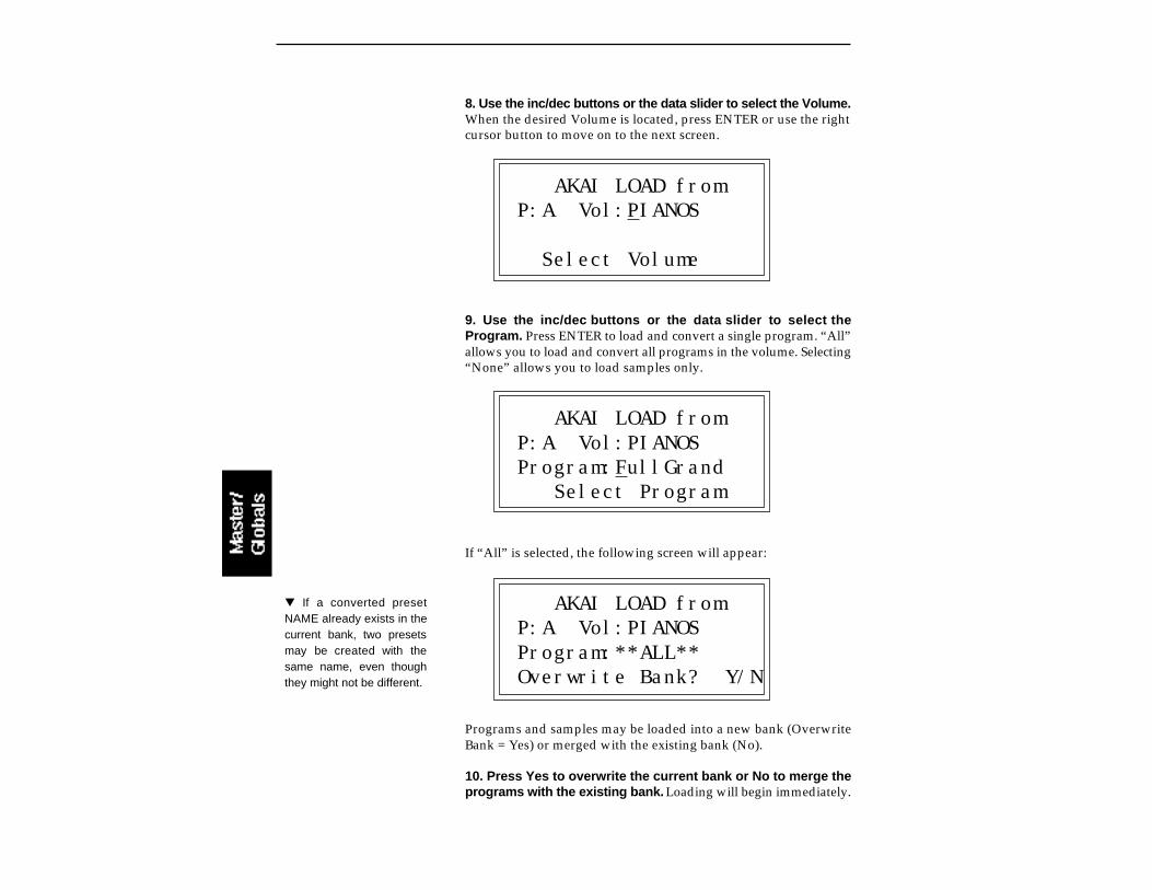
8. Use the inc/dec buttons or the data slider to select the Volume.When the desired Volume is located, press ENTER or use the rightcursor button to move on to the next screen.
AKAI LOAD fromP:A Vol:PIANOS
Select Volume
9. Use the inc/dec buttons or the data slider to select theProgram. Press ENTER to load and convert a single program. “All”allows you to load and convert all programs in the volume. Selecting“None” allows you to load samples only.
AKAI LOAD fromP:A Vol:PIANOSProgram:FullGrand Select Program
If “All” is selected, the following screen will appear:
AKAI LOAD fromP:A Vol:PIANOSProgram:**ALL**Overwrite Bank? Y/N
Programs and samples may be loaded into a new bank (OverwriteBank = Yes) or merged with the existing bank (No).
10. Press Yes to overwrite the current bank or No to merge theprograms with the existing bank. Loading will begin immediately.
If a converted presetNAME already exists in thecurrent bank, two presetsmay be created with thesame name, even thoughthey might not be different.
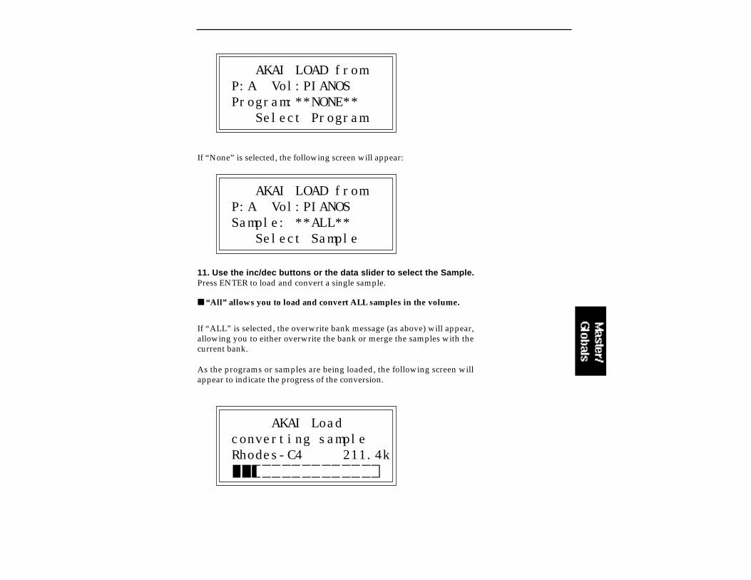
AKAI LOAD fromP:A Vol:PIANOSProgram:**NONE** Select Program
If “None” is selected, the following screen will appear:
AKAI LOAD fromP:A Vol:PIANOSSample: **ALL** Select Sample
11. Use the inc/dec buttons or the data slider to select the Sample.Press ENTER to load and convert a single sample.
“All” allows you to load and convert ALL samples in the volume.
If “ALL” is selected, the overwrite bank message (as above) will appear,allowing you to either overwrite the bank or merge the samples with thecurrent bank.
As the programs or samples are being loaded, the following screen willappear to indicate the progress of the conversion.
AKAI Loadconverting sampleRhodes-C4 211.4k
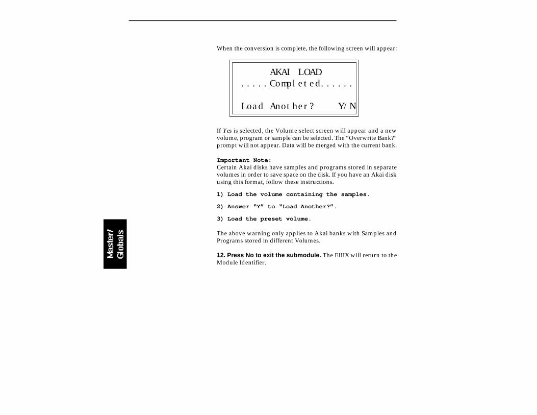
When the conversion is complete, the following screen will appear:
AKAI LOAD.....Completed......
Load Another? Y/N
If Yes is selected, the Volume select screen will appear and a newvolume, program or sample can be selected. The “Overwrite Bank?”prompt will not appear. Data will be merged with the current bank.
Important Note:Certain Akai disks have samples and programs stored in separatevolumes in order to save space on the disk. If you have an Akai diskusing this format, follow these instructions.
1) Load the volume containing the samples.
2) Answer “Y” to “Load Another?”.
3) Load the preset volume.
The above warning only applies to Akai banks with Samples andPrograms stored in different Volumes.
12. Press No to exit the submodule. The EIIIX will return to theModule Identifier.
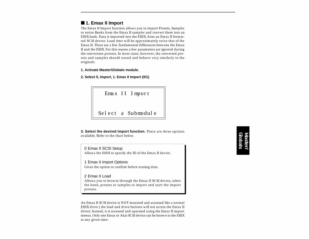
1. Emax II ImportThe Emax II Import function allows you to import Presets, Samplesor entire Banks from the Emax II sampler and convert them into anEIIIX bank. Data is imported into the EIIIX, from an Emax II format-ted SCSI device. Load time will be approximately twice that of theEmax II. There are a few fundamental differences between the EmaxII and the EIIIX. For this reason a few parameters are ignored duringthe conversion process. In most cases, however, the converted pre-sets and samples should sound and behave very similarly to theoriginals.
1. Activate Master/Globals module.
2. Select 0, Import, 1. Emax II Import (0/1)
Emax II Import
Select a Submodule
3. Select the desired import function. There are three optionsavailable. Refer to the chart below.
0 Emax II SCSI SetupAllows the EIIIX to specify the ID of the Emax II device.
1 Emax II Import OptionsGives the option to confirm before erasing data.
2 Emax II LoadAllows you to browse through the Emax II SCSI device, selectthe bank, presets or samples to import and start the importprocess.
An Emax II SCSI device is NOT mounted and accessed like a normalEIIIX drive ( the load and drive buttons will not access the Emax IIdrive). Instead, it is accessed and operated using the Emax II importmenus. Only one Emax or Akai SCSI device can be known to the EIIIXat any given time.

4. Press 0 on the keypad to select Emax II SCSI Setup. This stepis necessary for the EIIIX to recognize the Emax II SCSI device. Thedisplay shows:
Emax II SCSI SETUPSCSI ID: SEARCHTOSHIBA CD-ROM DRIVESelect SEARCH or ID
The setup screen is used to select the SCSI ID of the attached Emax IISCSI device. The SCSI ID may be selected by using the inc/decbuttons, or by typing the digit (1-7) directly using the EIIIX keypad.The default choice, “Search” instructs the EIIIX to search for the firstEmax II device in the SCSI chain. Normally you will always use“Search” unless you want to select a specific Emax II device out ofseveral on the SCSI bus. Press ENTER, to confirm your choice andreturn to the option select screen.
5. Press 1 to select the Import Options screen. The followingscreen will appear. When this function is set to Yes, the EIIIX willissue an extra prompt whenever a load operation is about to destroythe current bank. Press ENTER after selecting your choice.
EmaxII IMPORT OPTIONS
Confirm new bank: no
6. Press 2 to select the Emax II Load screen. Immediately afterLoad is selected, the EIIIX will attempt to read and verify the EmaxII disk using Search mode or using the SCSI ID selected in the SCSISetup screen.
Emax II Setup
Drive 0 cannot be usedsince the EIIIX uses thisnumber for the floppy disk.
Emax II Load
Emax II ImportOptions
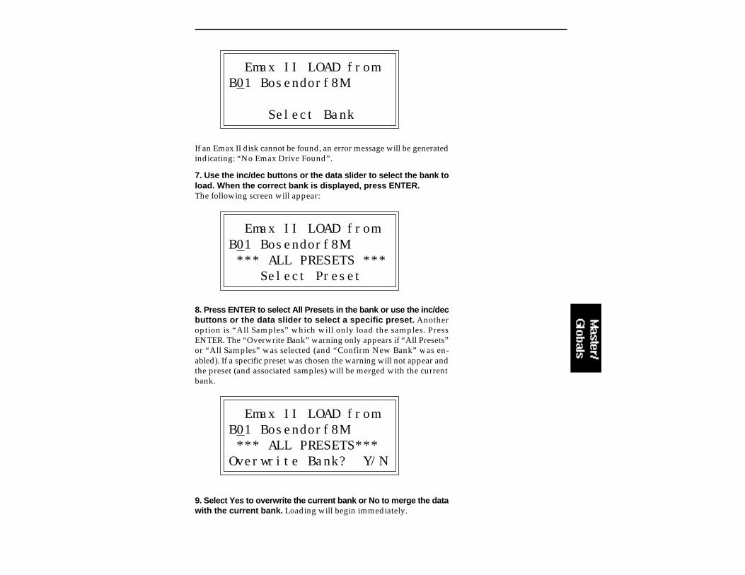
Emax II LOAD fromB01 Bosendorf8M
Select Bank
If an Emax II disk cannot be found, an error message will be generatedindicating: “No Emax Drive Found”.
7. Use the inc/dec buttons or the data slider to select the bank toload. When the correct bank is displayed, press ENTER.The following screen will appear:
Emax II LOAD fromB01 Bosendorf8M *** ALL PRESETS *** Select Preset
8. Press ENTER to select All Presets in the bank or use the inc/decbuttons or the data slider to select a specific preset. Anotheroption is “All Samples” which will only load the samples. PressENTER. The “Overwrite Bank” warning only appears if “All Presets”or “All Samples” was selected (and “Confirm New Bank” was en-abled). If a specific preset was chosen the warning will not appear andthe preset (and associated samples) will be merged with the currentbank.
Emax II LOAD fromB01 Bosendorf8M *** ALL PRESETS***Overwrite Bank? Y/N
9. Select Yes to overwrite the current bank or No to merge the datawith the current bank. Loading will begin immediately.

Emax II LOADConverting sample...S01 647.0k
Since samples do not have names in the Emax II, they are importedinto the EIIIX with Sxx appended to the bank name, where xx is thenumber of the sample. Example: Bosendorf8M_S02.
Bank and preset names retain their names from Emax II.
Emax II LOAD.....Completed......
Load Another? Y/N
If Yes is selected, the Bank select screen will appear and a new Bank,Preset or Sample can be selected.
10. Press No to exit the submodule. The EIIIX will return to theModule Identifier.
Sample Size
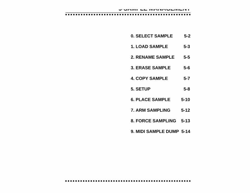
5-SAMPLE MANAGEMENT
0. SELECT SAMPLE 5-2
1. LOAD SAMPLE 5-3
2. RENAME SAMPLE 5-5
3. ERASE SAMPLE 5-6
4. COPY SAMPLE 5-7
5. SETUP 5-8
6. PLACE SAMPLE 5-10
7. ARM SAMPLING 5-12
8. FORCE SAMPLING 5-13
9. MIDI SAMPLE DUMP 5-14
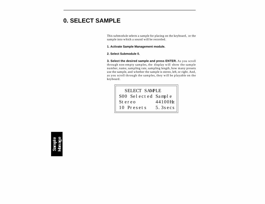
This submodule selects a sample for placing on the keyboard, or thesample into which a sound will be recorded.
1. Activate Sample Management module.
2. Select Submodule 0.
3. Select the desired sample and press ENTER. As you scrollthrough non-empty samples, the display will show the samplenumber, name, sampling rate, sampling length, how many presetsuse the sample, and whether the sample is stereo, left, or right. And,as you scroll through the samples, they will be playable on thekeyboard.
SELECT SAMPLES00 Selected SampleStereo 44100Hz10 Presets 5.3secs
0. SELECT SAMPLE
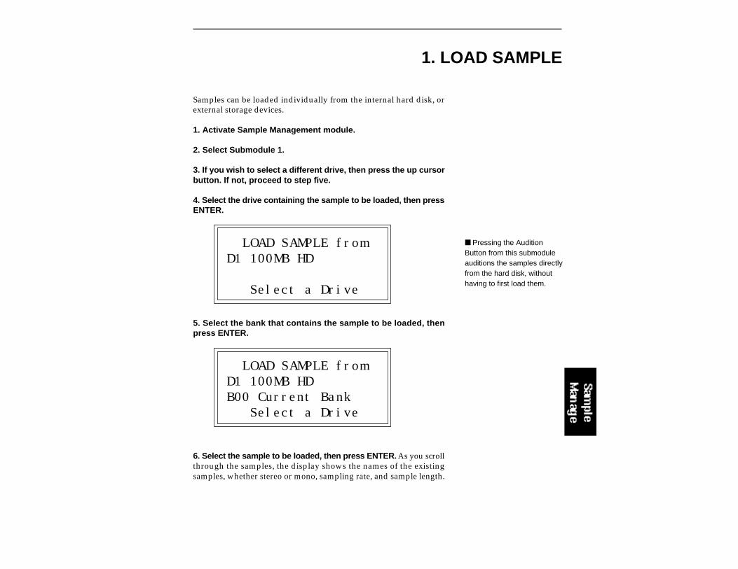
Samples can be loaded individually from the internal hard disk, orexternal storage devices.
1. Activate Sample Management module.
2. Select Submodule 1.
3. If you wish to select a different drive, then press the up cursorbutton. If not, proceed to step five.
4. Select the drive containing the sample to be loaded, then pressENTER.
LOAD SAMPLE fromD1 100MB HD
Select a Drive
5. Select the bank that contains the sample to be loaded, thenpress ENTER.
LOAD SAMPLE fromD1 100MB HDB00 Current Bank Select a Drive
6. Select the sample to be loaded, then press ENTER. As you scrollthrough the samples, the display shows the names of the existingsamples, whether stereo or mono, sampling rate, and sample length.
1. LOAD SAMPLE
Pressing the AuditionButton from this submoduleauditions the samples directlyfrom the hard disk, withouthaving to first load them.
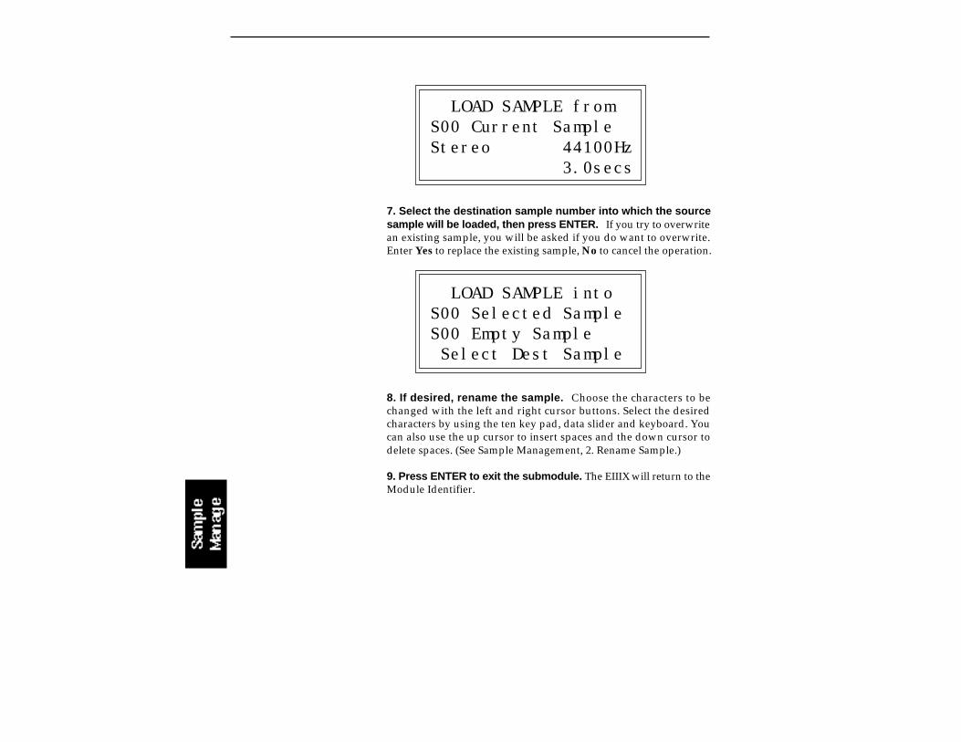
LOAD SAMPLE fromS00 Current SampleStereo 44100Hz 3.0secs
7. Select the destination sample number into which the sourcesample will be loaded, then press ENTER. If you try to overwritean existing sample, you will be asked if you do want to overwrite.Enter Yes to replace the existing sample, No to cancel the operation.
LOAD SAMPLE intoS00 Selected SampleS00 Empty Sample Select Dest Sample
8. If desired, rename the sample. Choose the characters to bechanged with the left and right cursor buttons. Select the desiredcharacters by using the ten key pad, data slider and keyboard. Youcan also use the up cursor to insert spaces and the down cursor todelete spaces. (See Sample Management, 2. Rename Sample.)
9. Press ENTER to exit the submodule. The EIIIX will return to theModule Identifier.
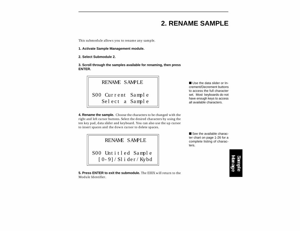
2. RENAME SAMPLE
This submodule allows you to rename any sample.
1. Activate Sample Management module.
2. Select Submodule 2.
3. Scroll through the samples available for renaming, then pressENTER.
RENAME SAMPLE
S00 Current Sample Select a Sample
4. Rename the sample. Choose the characters to be changed with theright and left cursor buttons. Select the desired characters by using theten key pad, data slider and keyboard. You can also use the up cursorto insert spaces and the down cursor to delete spaces.
RENAME SAMPLE
S00 Untitled Sample [0-9]/Slider/Kybd
5. Press ENTER to exit the submodule. The EIIIX will return to theModule Identifier.
Use the data slider or In-crement/Decrement buttonsto access the full characterset. Most keyboards do nothave enough keys to accessall available characters.
See the available charac-ter chart on page 1-26 for acomplete listing of charac-ters.

3. ERASE SAMPLE
Individual samples can be erased from the bank loaded into theEmulator IIIX, and newly created locked samples currently in mem-ory can be erased using this function.
1. Activate Sample Management module.
2. Select Submodule 3.
3. Select the sample to be erased, then press ENTER.
ERASE SAMPLES00 Current Sample
Select a Sample
4. If the sample is stereo, select whether you want to erase the leftside, right side, or the entire stereo sample.
ERASE SAMPLES00 Selected SampleSide: Stereo Select L/R/Stereo
5. Decide if you really want to erase the sample. The EIIIX willinquire if you are sure.
6. Press Yes to erase the sample, or No to cancel the operation.In either case the EIIIX will return to the Module Identifier.
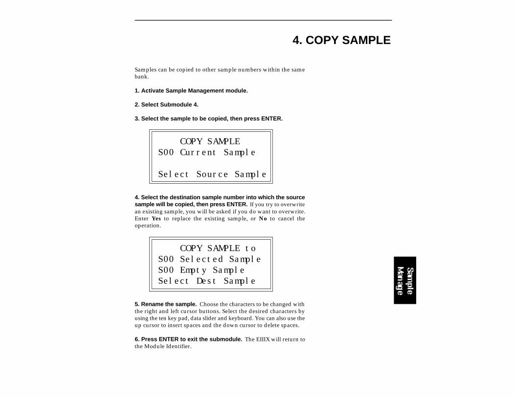
4. COPY SAMPLE
Samples can be copied to other sample numbers within the samebank.
1. Activate Sample Management module.
2. Select Submodule 4.
3. Select the sample to be copied, then press ENTER.
COPY SAMPLES00 Current Sample
Select Source Sample
4. Select the destination sample number into which the sourcesample will be copied, then press ENTER. If you try to overwritean existing sample, you will be asked if you do want to overwrite.Enter Yes to replace the existing sample, or No to cancel theoperation.
COPY SAMPLE toS00 Selected SampleS00 Empty SampleSelect Dest Sample
5. Rename the sample. Choose the characters to be changed withthe right and left cursor buttons. Select the desired characters byusing the ten key pad, data slider and keyboard. You can also use theup cursor to insert spaces and the down cursor to delete spaces.
6. Press ENTER to exit the submodule. The EIIIX will return tothe Module Identifier.

5. SETUP
In this submodule, you will prepare the Emulator IIIX for sampling.Either the digital input or the optional analog inputs can be sampled.
1. Activate Sample module. If you want to sample into the samplenumber shown on the display, you need do nothing except proceedto the next step. To sample into a different sample number, refer to 0.Select Sample.
2. Select Submodule 5.
3. Use the cursor buttons to select one of the following parame-ters to edit. Page one displays:
SETUP AdcGain: -10Thresh: |L: On |R: Off |
Gain: Set the analog sample level with the data slider so that theleft and right side meters indicate optimum sampling level. Play thesound to be sampled and observe the bar graph display. The signallevel should be set so that the peak bar comes close to the extremeright side without actually reaching it. The gain is adjustable from-10 dB to +40 dB in 2 dB steps. This control has no effect on the digitalinput.
Thresh: (Threshold) Set the sampling threshold with the dataslider. If you arm sampling (7. Arm Sampling) and the signal to besampled exceeds the threshold, sampling will begin.
L: (Left Channel) Line three shows the left input level, record status,and whether on or off. Press On or Off to enable or disable recordinginto the left channel. When sampling into one channel only, turn offthe other channel to conserve memory.
R: (Right Channel) Line four shows the right input level, recordstatus, and whether on or off. Press On or Off to enable or disablerecording into the left channel. When sampling into one channelonly, turn off the other channel to conserve memory.
4. Select page two by pressing the right cursor button. Page twoshows:
The EIIIX will actuallycapture samples just be-fore the threshold isexceded to preserve theattack portion of the sound(12mS at 44100Hz, 17mSat 29400Hz).
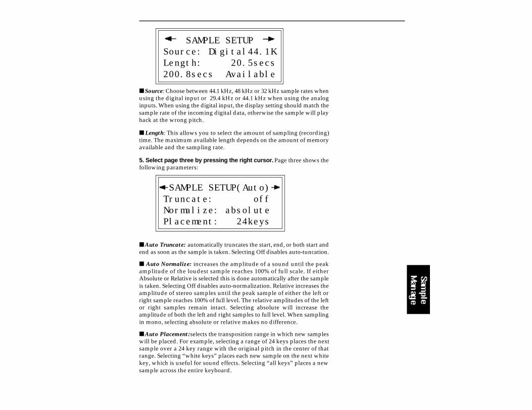
SAMPLE SETUPSource: Digital44.1KLength: 20.5secs200.8secs Available
Source: Choose between 44.1 kHz, 48 kHz or 32 kHz sample rates whenusing the digital input or 29.4 kHz or 44.1 kHz when using the analoginputs. When using the digital input, the display setting should match thesample rate of the incoming digital data, otherwise the sample will playback at the wrong pitch.
Length: This allows you to select the amount of sampling (recording)time. The maximum available length depends on the amount of memoryavailable and the sampling rate.
5. Select page three by pressing the right cursor. Page three shows thefollowing parameters:
SAMPLE SETUP(Auto)Truncate: offNormalize: absolutePlacement: 24keys
Auto Truncate: automatically truncates the start, end, or both start andend as soon as the sample is taken. Selecting Off disables auto-tuncation.
Auto Normalize: increases the amplitude of a sound until the peakamplitude of the loudest sample reaches 100% of full scale. If eitherAbsolute or Relative is selected this is done automatically after the sampleis taken. Selecting Off disables auto-normalization. Relative increases theamplitude of stereo samples until the peak sample of either the left orright sample reaches 100% of full level. The relative amplitudes of the leftor right samples remain intact. Selecting absolute will increase theamplitude of both the left and right samples to full level. When samplingin mono, selecting absolute or relative makes no difference.
Auto Placement: selects the transposition range in which new sampleswill be placed. For example, selecting a range of 24 keys places the nextsample over a 24 key range with the original pitch in the center of thatrange. Selecting “white keys” places each new sample on the next whitekey, which is useful for sound effects. Selecting “all keys” places a newsample across the entire keyboard.

6. Select page four by pressing the right cursor. The display shows:
SAMPLE SETUP
Monitor through while sampling: on
Monitor through while sampling allows you to hear the sampled signalthrough the main outputs while sampling is occurring. Monitor through isNOT active at any other time. The VU meters are disabled during the actualsampling process but are active during the setup procedure. With MonitorTthrough “Off”, the main outputs remain silent during sampling.
7. Press ENTER to exit the submodule. The EIIIX will return to theModule Identifier.
Monitor Through allowsyou to monitor through themain outputs. while samplingis occurring. It is NOT activein the VU meter screen.
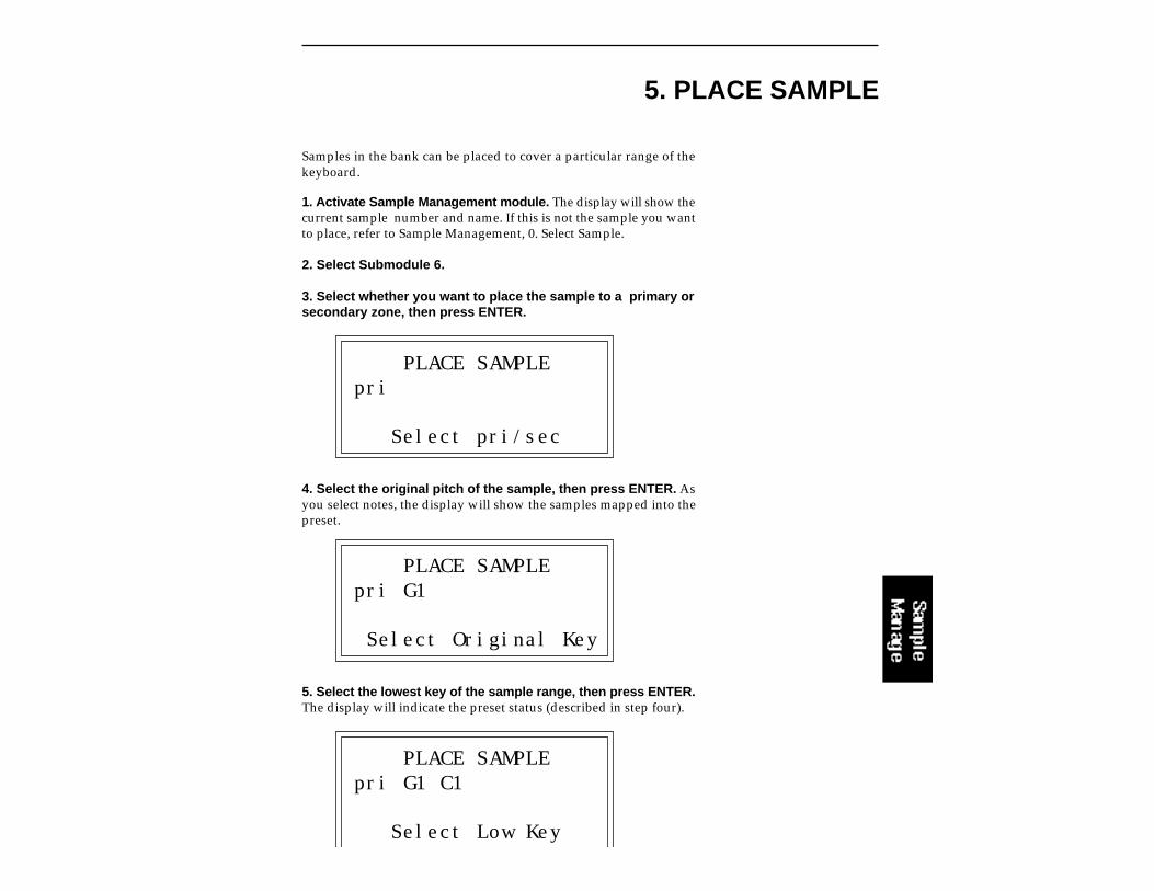
5. PLACE SAMPLE
Samples in the bank can be placed to cover a particular range of thekeyboard.
1. Activate Sample Management module. The display will show thecurrent sample number and name. If this is not the sample you wantto place, refer to Sample Management, 0. Select Sample.
2. Select Submodule 6.
3. Select whether you want to place the sample to a primary orsecondary zone, then press ENTER.
PLACE SAMPLEpri
Select pri/sec
4. Select the original pitch of the sample, then press ENTER. Asyou select notes, the display will show the samples mapped into thepreset.
PLACE SAMPLEpri G1
Select Original Key
5. Select the lowest key of the sample range, then press ENTER.The display will indicate the preset status (described in step four).
PLACE SAMPLEpri G1 C1
Select Low Key
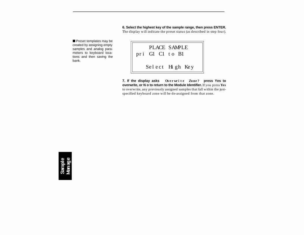
6. Select the highest key of the sample range, then press ENTER.The display will indicate the preset status (as described in step four).
PLACE SAMPLEpri G1 C1 to B1
Select High Key
7. If the display asks Overwrite Zone? press Yes tooverwrite, or N o to return to the Module Identifier. If you press Yesto overwrite, any previously assigned samples that fall within the just-specified keyboard zone will be de-assigned from that zone.
Preset templates may becreated by assigning emptysamples and analog para-meters to keyboard loca-tions and then saving thebank.
Upon initiating this submodule, the EIIIX will begin sampling assoon as the sound to be sampled exceeds the threshold set in Sample,5. Setup.
1. Activate Sample module.
2. Select Submodule 7. If you did not select a specific empty sampleprior to arming, the first empty sample will be automatically selected.To overwrite an existing sample, erase it first.
3. Play the sound to be sampled. When the sound level exceeds thethreshold set in 5. Setup, the display will indicate that sampling hasbegun.
4. Terminate sampling. This will occur automatically after reachingthe end of the sample length set in 5. Setup, or if the EIIIXruns out ofmemory. To stop sampling manually, press ESCAPE. In any case, thedisplay will return to the Module Identifier.
5. Decide if you like the sample. Play the keyboard. If you don't likethe sample, re-arm sampling or force sampling and re-sample beforede-activating the module. Once you de-activate the module, thesample will be locked against re-sampling. To erase a locked sample,use 3. Erase Sample.
See also “Basic Sampling”in the Guided Tours sectionof this manual.
7. ARM SAMPLING

Force Sampling lets you initiate sampling manually as an alternativeto threshold-sensitive sampling. This is useful for situations where thesignal to be sampled is more or less continuous. Continuous signalsgreatly complicate the threshold-setting process described in Sample,5. Setup. Upon initiating this submodule, the Emulator IIIX will beginsampling immediately.
1. Activate Sample module.
2. Select Submodule 8 when you are ready to begin sampling. Ifyou did not select a specific empty sample prior to force sampling, thefirst empty sample will be automatically selected. To overwrite anexisting sample, erase it first.
3. Wait as the signal is sampled.
4. Terminate sampling. This will occur automatically after reachingthe end of the sample length (if set in 5. Setup), or if the EIIIXruns outof memory. To stop sampling manually, press ESCAPE. In any case,the display will return to the Module Identifier.
5. Decide if you like the sample. Play the keyboard. If you don't likethe sample, re-arm sampling or force sampling again and re-sampleBEFORE de-activating the module. Once you de-activate the module,the sample will be protected against re-sampling.
See also “Basic Sampling”in the Guided Tours sectionof this manual.
8. FORCE SAMPLING

9. MIDI SAMPLE DUMP
MIDI Sample Dump allows sample data to be transferred to and fromthe EIIIX using the MIDI Sample Dump Standard. The EIIIX cantransmit sample data with a word size of either 14 or 16 bits (Certaininstruments such as the SP-1200 require the use of the 14 bit wordsize). In addition, for instruments that use 14 bits or less, 14 bit modetransmits data 30% faster.
Before initiating MIDI Sample Dump, make sure that the MIDI cablesare properly connected. A single MIDI cable (open-loop) is sufficientbut the data transfer will be much faster if two MIDI cables are used(closed-loop). The closed-loop allows the two units to handshake andprevents idle time between each data packet. The cables should beconnected between the MIDI In and MIDI Out of both units.
In the Sample Dump Standard and in the EIIIX, samples are assignednumbers. The EIIIX sample number and the MIDI sample numberremain the same. For example, sample #36 transferred from anotherdevice to the EIIIX will be placed in sample location 36.
When transferring samples to the Emax, the sample location num-bers correspond to sample dump MIDI key numbers. For example, asample placed in location #60 in the EIIIX, once transmitted, will beplaced on MIDI key #60 (middle C) of the Emax. If sample location#36 is chosen as a reception location on the EIIIX, the EIIIX willrequest that the sample placed on MIDI key # 36 (C1) of the Emax besent.
1. Activate Sample Management module.
2. Select Submodule 9.
3. Select whether you want to transmit or receive a sample andpress ENTER.
SAMPLE DUMPDirection: Transmit
Select Direction
A "closed-loop" connec-tion greatly accelerates MIDIdata transfer.
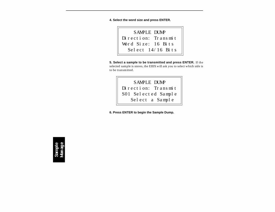
4. Select the word size and press ENTER.
SAMPLE DUMPDirection: TransmitWord Size: 16 Bits Select 14/16 Bits
5. Select a sample to be transmitted and press ENTER. If theselected sample is stereo, the EIIIX will ask you to select which side isto be transmitted.
SAMPLE DUMPDirection: TransmitS01 Selected Sample Select a Sample
6. Press ENTER to begin the Sample Dump.
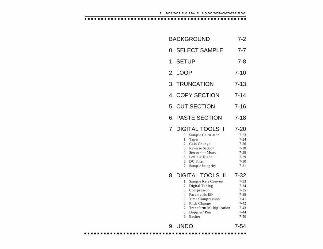
7-DIGITAL PROCESSING
BACKGROUND 7-2
0. SELECT SAMPLE 7-7
1. SETUP 7-8
2. LOOP 7-10
3. TRUNCATION 7-13
4. COPY SECTION 7-14
5. CUT SECTION 7-16
6. PASTE SECTION 7-18
7. DIGITAL TOOLS I 7-200. Sample Calculator 7-231. Taper 7-242. Gain Change 7-263. Reverse Section 7-284. Stereo <-> Mono 7-295. Left <-> Right 7-296. DC Filter 7-307. Sample Integrity 7-31
8. DIGITAL TOOLS II 7-321. Sample Rate Convert 7-332. Digital Tuning 7-343. Compressor 7-354. Parametric EQ 7-395. Time Compression 7-416. Pitch Change 7-427. Transform Multiplication 7-438. Doppler/Pan 7-449. Exciter 7-50
9. UNDO 7-54
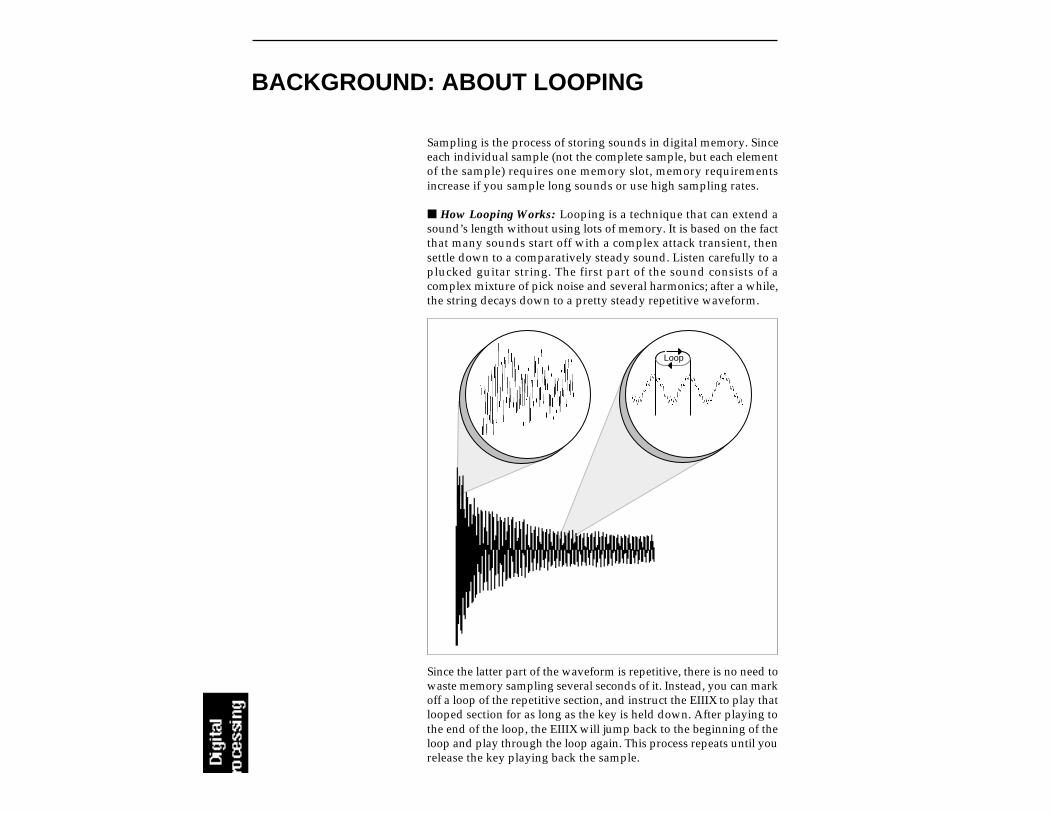
BACKGROUND: ABOUT LOOPING
Sampling is the process of storing sounds in digital memory. Sinceeach individual sample (not the complete sample, but each elementof the sample) requires one memory slot, memory requirementsincrease if you sample long sounds or use high sampling rates.
How Looping Works: Looping is a technique that can extend asound’s length without using lots of memory. It is based on the factthat many sounds start off with a complex attack transient, thensettle down to a comparatively steady sound. Listen carefully to aplucked guitar string. The first part of the sound consists of acomplex mixture of pick noise and several harmonics; after a while,the string decays down to a pretty steady repetitive waveform.
Loop
Since the latter part of the waveform is repetitive, there is no need towaste memory sampling several seconds of it. Instead, you can markoff a loop of the repetitive section, and instruct the EIIIX to play thatlooped section for as long as the key is held down. After playing tothe end of the loop, the EIIIX will jump back to the beginning of theloop and play through the loop again. This process repeats until yourelease the key playing back the sample.
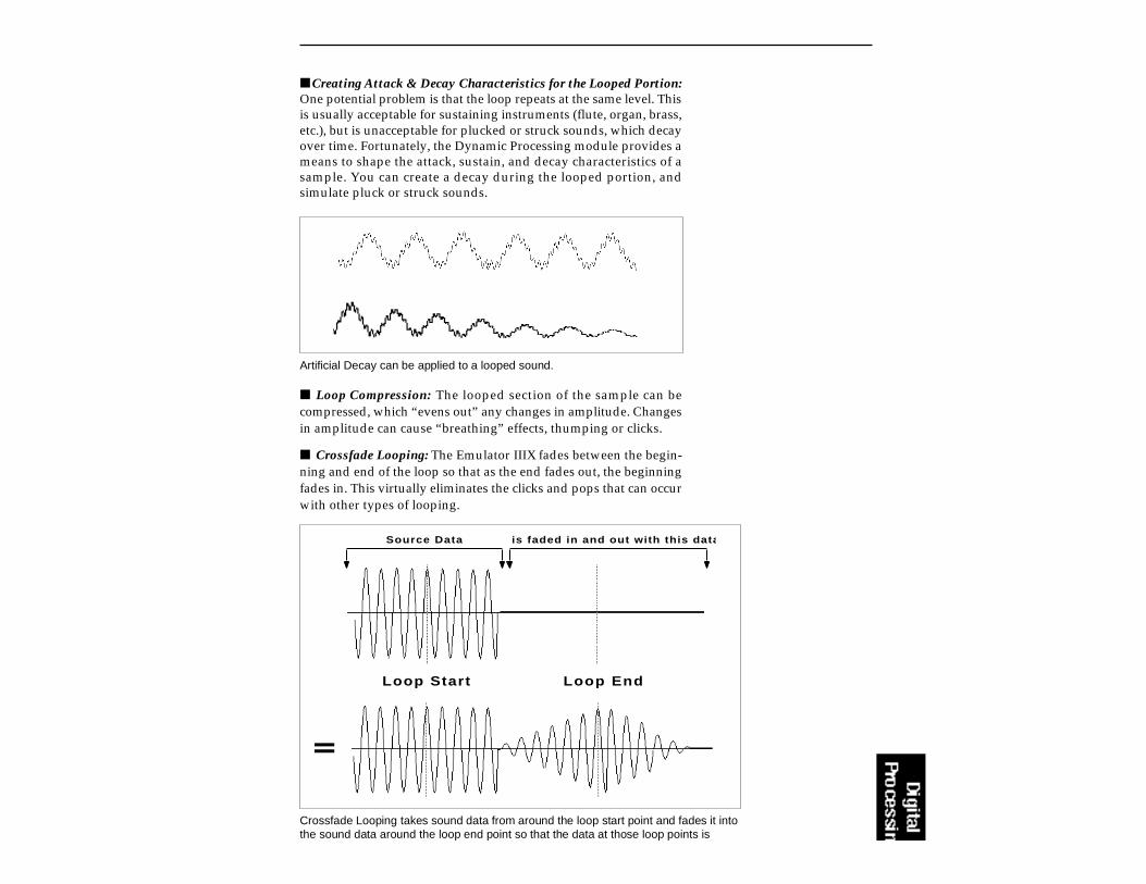
Creating Attack & Decay Characteristics for the Looped Portion:One potential problem is that the loop repeats at the same level. Thisis usually acceptable for sustaining instruments (flute, organ, brass,etc.), but is unacceptable for plucked or struck sounds, which decayover time. Fortunately, the Dynamic Processing module provides ameans to shape the attack, sustain, and decay characteristics of asample. You can create a decay during the looped portion, andsimulate pluck or struck sounds.
Artificial Decay can be applied to a looped sound.
Crossfade Looping takes sound data from around the loop start point and fades it intothe sound data around the loop end point so that the data at those loop points is
Loop Start Loop End
Source Data is faded in and out with this data
Loop Compression: The looped section of the sample can becompressed, which “evens out” any changes in amplitude. Changesin amplitude can cause “breathing” effects, thumping or clicks.
Crossfade Looping: The Emulator IIIX fades between the begin-ning and end of the loop so that as the end fades out, the beginningfades in. This virtually eliminates the clicks and pops that can occurwith other types of looping.

BACKGROUND: CUT, COPY, PASTE & UNDO
Imagine a printout of a sample. Now imagine that you have a pair ofscissors capable of cutting a piece out of that sample (or a copy of thatpiece if you don’t want to affect the original), as well as a clipboardto neatly hold the cut or copied piece. Now imagine that you caneither perfectly insert the clipboard contents at any given point inany sample, or mix the clipboard contents in with any sample,starting at any designated point. The Emulator IIIX can do all this,and all electronically. The EIIIX also provides Auto Correlation andoptional Crossfade functions that result in seamless transitionsbetween the cut, copied, and pasted parts.
CLIPBOARD DATA. The clipboard will retain data until replaced by other data to be copied, cut, or backed up.This occurs with several EIIIX operations where you want to be able to undo an action that doesn’t work out asanticipated. Since clipboard data stays intact when you call up another sample, data can be cut or copied fromone sample and pasted to another.
The clipboard contents aredesignated as Sample 00.
Undo and Redo: During several Emulator IIIX digital processingoperations such as cut, paste, and sample rate conversion, the EIIIXwill automatically back up the sample being processed and store thisbackup on the system drive. If you do not like the results of theprocessing, you can call up the Undo function, and restore theoriginal sample from the system drive. (Ah, if only life itself was sosimple.) Best of all, the processed sample will now move onto thesystem drive. Thus, if you decide you liked the processed versionbetter after all, you can actually undo the undo. (Redo.)
Insufficient System Drive Memory: The display will inform you ifthere is not enough memory to back up a sample onto the systemdrive. You then have two choices: either free up some additionalmemory by erasing banks on the system drive, or call up the Undofunction (Digital Processing, 9. Undo) and disable the backup proc-ess. Of course, if backup is disabled, you will not be able to undo anoperation.
Typical Applications: Typical cut/copy/paste applicationswould be to splice the beginning of one sample to the end of another,or to mix two samples together to conserve memory. (Do this bycopying an entire sample, then pasting it at the beginning of thesecond sample using the mix option.) You can splice an attacktransient on to a synthesizer waveform loop to produce realisticsounds that take up virtually no memory, or take out a pop or clickin a sample. Another possibility is for flanging and chorusing. Paste(mix) a sample to itself, offset from the beginning by a few hundredsamples or so, to thicken up the sound.
We suggest you practice cut, copy, and paste techniques on a spokenphrase. Samples of political speeches can be particularly amusingwhen subjected to cut and paste operations.

The Scrub Wheel is an Emulator IIIX function that allows you to usethe pitch wheel in many Digital Processing functions to quicklymove through a sound, similar in concept to rocking the reels of areel-to-reel tape recorder. The scrub wheel makes it easy to locate aparticular section of a sound because you are able to hear the soundas you move through it.
To use the scrub wheel, move the pitch wheel of the EIIIX or yourMIDI keyboard while in a Digital Processing function such asTruncation or Looping. If the pitch wheel is moved slightly forward,the sound will play slowly through its length. If the wheel is pushedforward all the way, the sound will play through faster. If the wheelis moved backwards (towards you) the sound will play backwardsthrough the sound. The scrub wheel operates like the accelerator onyour car: the harder you press it, the faster it goes.
EIIIX SCRUB WHEEL. Move the wheel slightly to advance slowly throughthe sound. Move the wheel more to advance quickly through the sound.
BACKGROUND: THE SCRUB WHEEL
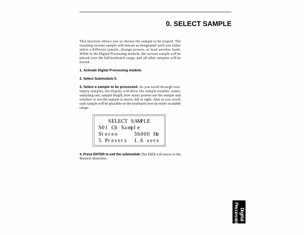
0. SELECT SAMPLE
This function allows you to choose the sample to be looped. Theresulting current sample will remain as designated until you eitherselect a different sample, change presets, or load another bank.While in the Digital Processing module, the current sample will beplaced over the full keyboard range, and all other samples will bemuted.
1. Activate Digital Processing module.
2. Select Submodule 0.
3. Select a sample to be processed. As you scroll through non-empty samples, the display will show the sample number, name,sampling rate, sample length, how many presets use the sample andwhether or not the sample is stereo, left or right. Also as you scroll,each sample will be playable on the keyboard over its entire availablerange.
SELECT SAMPLES01 C6 SampleStereo 36000 Hz5 Presets 1.6 secs
4. Press ENTER to exit the submodule. The EIIIX will return to theModule Identifier.
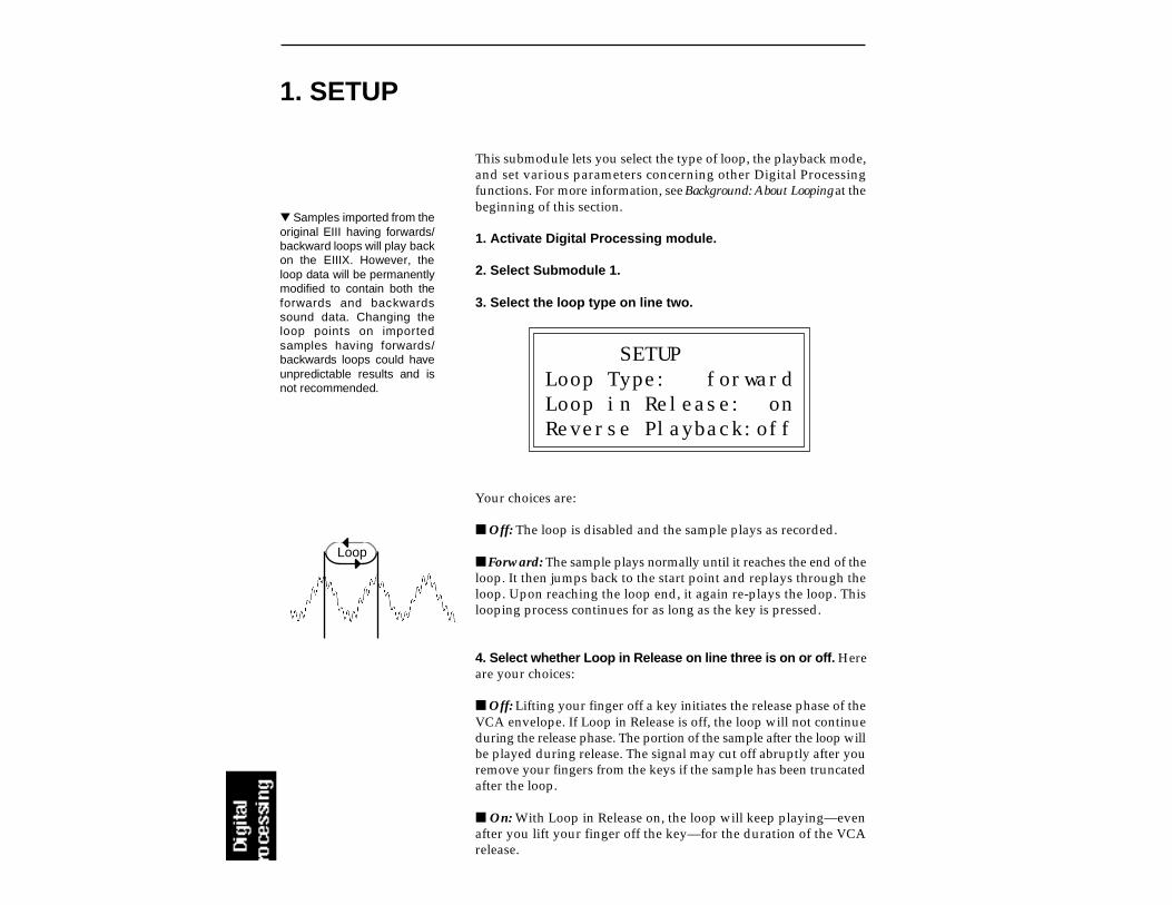
1. SETUP
This submodule lets you select the type of loop, the playback mode,and set various parameters concerning other Digital Processingfunctions. For more information, see Background: About Looping at thebeginning of this section.
1. Activate Digital Processing module.
2. Select Submodule 1.
3. Select the loop type on line two.
SETUPLoop Type: forwardLoop in Release: onReverse Playback:off
Your choices are:
Off: The loop is disabled and the sample plays as recorded.
Forward: The sample plays normally until it reaches the end of theloop. It then jumps back to the start point and replays through theloop. Upon reaching the loop end, it again re-plays the loop. Thislooping process continues for as long as the key is pressed.
4. Select whether Loop in Release on line three is on or off. Hereare your choices:
Off: Lifting your finger off a key initiates the release phase of theVCA envelope. If Loop in Release is off, the loop will not continueduring the release phase. The portion of the sample after the loop willbe played during release. The signal may cut off abruptly after youremove your fingers from the keys if the sample has been truncatedafter the loop.
On: With Loop in Release on, the loop will keep playing—evenafter you lift your finger off the key—for the duration of the VCArelease.
Samples imported from theoriginal EIII having forwards/backward loops will play backon the EIIIX. However, theloop data will be permanentlymodified to contain both theforwards and backwardssound data. Changing theloop points on importedsamples having forwards/backwards loops could haveunpredictable results and isnot recommended.
Loop

5. Select whether Reverse Playback on line four is on or off. Hereare your choices:
Off: The sample plays back as recorded.
On: The sample is played back in the reverse order in which it wasrecorded. For example, a percussive sound, when played back-wards, will have an attack time instead of a decay time.
10. Press ENTER to exit the submodule. The EIIIX will return tothe Module Identifier.
If a sample ends in a loop,playing it backwards will re-peat the loop. The sample willnot play back prior to the loopstart.

If you have a difficult time finding good loop points, the EIIIX canassist you with the Auto Correlation function. If Auto Correlationdoesn’t produce acceptable results, the beginning and end of a loopcan be Crossfaded to help mask loop discontinuities. For moreinformation, see Background: About Looping at the beginning of thissection.
1. Activate Digital Processing module.
2. Select Submodule 2.
LOOP secs samplesStart: 1.96 43280End: 3.54 78162Size: 1.58 34882
3. Select the values for the start point on line two and the loopsize on line four that give the best looping effect, then pressENTER. The left and right cursor will change the start point and/orsize so that the loop automatically falls on positive zero crossingpoints in the waveform.
The sample size equals the difference in samples between the startand end points. These settings interact in the following ways:
Changing the size will automatically change the endpoint, so that the difference in samples between the startand end points remains equal to the size.
Changing the start point will change the end point tomaintain a constant size.
Changing the end point changes the size, and the startpoint remains constant.
4. The display will inquire if you want to Auto Correlate. PressYES to Auto Correlate, or NO to proceed directly to step six,Compress Loop. Auto Correlation uses artificial intelligence tech-niques to choose optimum loop points. Without Auto Correlation,unless you are proficient with sampling techniques, loops willusually have discontinuities between the splice points that canproduce annoying ticks, pops, or other glitches.
2. LOOP
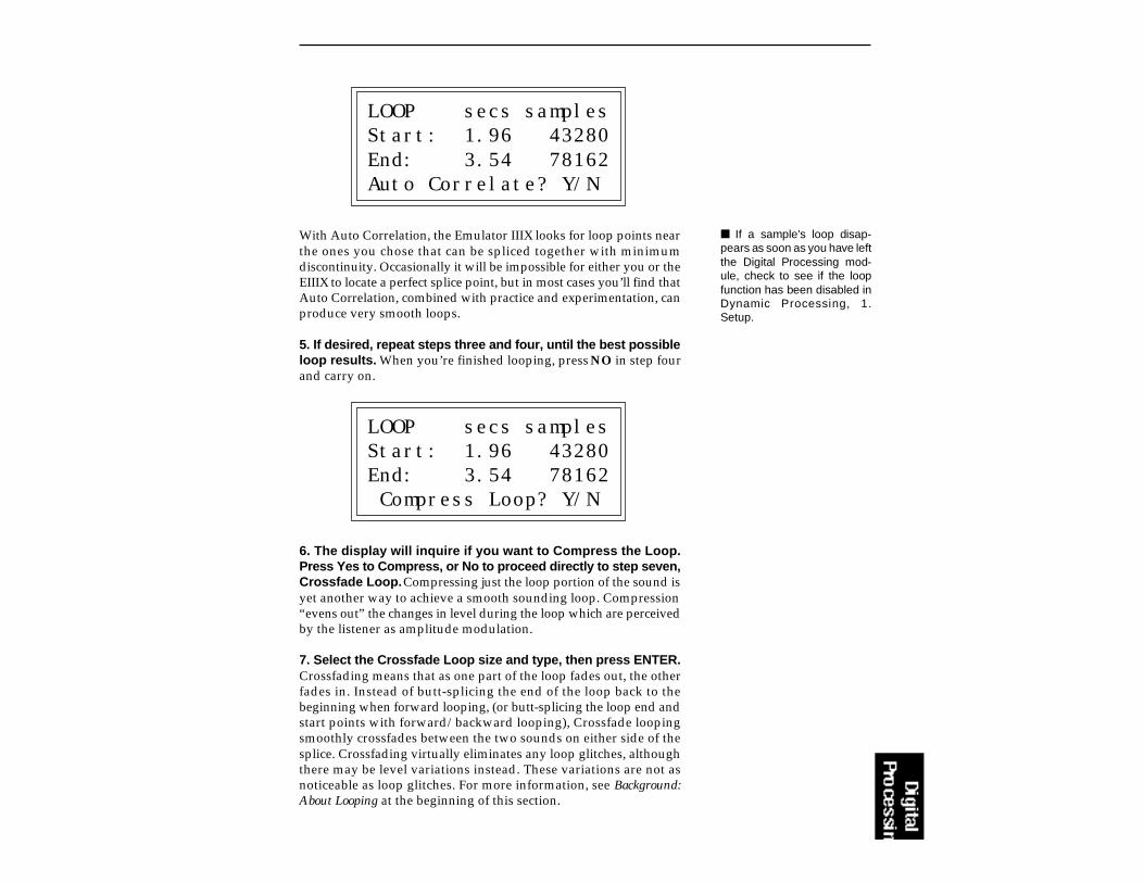
LOOP secs samplesStart: 1.96 43280End: 3.54 78162Auto Correlate? Y/N
With Auto Correlation, the Emulator IIIX looks for loop points nearthe ones you chose that can be spliced together with minimumdiscontinuity. Occasionally it will be impossible for either you or theEIIIX to locate a perfect splice point, but in most cases you’ll find thatAuto Correlation, combined with practice and experimentation, canproduce very smooth loops.
5. If desired, repeat steps three and four, until the best possibleloop results. When you’re finished looping, press NO in step fourand carry on.
LOOP secs samplesStart: 1.96 43280End: 3.54 78162 Compress Loop? Y/N
6. The display will inquire if you want to Compress the Loop.Press Yes to Compress, or No to proceed directly to step seven,Crossfade Loop. Compressing just the loop portion of the sound isyet another way to achieve a smooth sounding loop. Compression“evens out” the changes in level during the loop which are perceivedby the listener as amplitude modulation.
7. Select the Crossfade Loop size and type, then press ENTER.Crossfading means that as one part of the loop fades out, the otherfades in. Instead of butt-splicing the end of the loop back to thebeginning when forward looping, (or butt-splicing the loop end andstart points with forward/backward looping), Crossfade loopingsmoothly crossfades between the two sounds on either side of thesplice. Crossfading virtually eliminates any loop glitches, althoughthere may be level variations instead. These variations are not asnoticeable as loop glitches. For more information, see Background:About Looping at the beginning of this section.
If a sample's loop disap-pears as soon as you have leftthe Digital Processing mod-ule, check to see if the loopfunction has been disabled inDynamic Processing, 1.Setup.
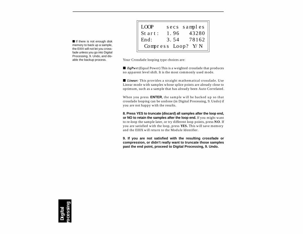
LOOP secs samplesStart: 1.96 43280End: 3.54 78162 Compress Loop? Y/N
Your Crossfade looping type choices are:
EqPwr: (Equal Power) This is a weighted crossfade that producesno apparent level shift. It is the most commonly used mode.
Linear: This provides a straight mathematical crossfade. UseLinear mode with samples whose splice points are already close tooptimum, such as a sample that has already been Auto Correlated.
When you press ENTER, the sample will be backed up so thatcrossfade looping can be undone (in Digital Processing, 9. Undo) ifyou are not happy with the results.
8. Press YES to truncate (discard) all samples after the loop end,or NO to retain the samples after the loop end. If you might wantto re-loop the sample later, or try different loop points, press NO. Ifyou are satisfied with the loop, press YES. This will save memoryand the EIIIX will return to the Module Identifier.
9. If you are not satisfied with the resulting crossfade orcompression, or didn’t really want to truncate those samplespast the end point, proceed to Digital Processing, 9. Undo.
If there is not enough diskmemory to back up a sample,the EIIIX will not let you cross-fade unless you go into DigitalProcessing, 9. Undo, and dis-able the backup process.

Truncation shortens a sample's length by trimming off individualsamples from the beginning and/or end. Truncation is most oftenused to remove unneeded portions of a sample to conserve memory,but it can also be used to change instrument characteristics such asremoving the attack from a plucked string note or isolating aparticular section of a sample.
1. Activate Digital Processing module.
2. Select Submodule 3.
3. Truncate the desired amount of samples from the start on linetwo and/or the end on line three, then press ENTER.
TRUNC secs samplesStart: 0.00 00001End: 2.43 53610Size: 2.43 53610
The sample size equals the difference in samples between the startand end points. Because of this, these settings interact with the sizevalue on line four in these ways:
Truncating the start will cause the size to change tomaintain a constant end point.
Truncating the end will cause the size to change tomaintain a constant start point.
4. If you are not satisfied with the resulting truncation, or wantto compare before and after, proceed to Digital Processing, 9.Undo.
3. TRUNCATION
The left and right cursorkeys will change the start andend points so that they auto-matically fall on positive zerocrossing points in the wave-form.

4. COPY SECTION
Portions of a sample can be cut, copied, and pasted to other samples,or the samples from which they came. The Copy function allows youto duplicate a section of a sample, and store that duplicate in a specialpart of memory called the clipboard. For more information see thesection Background: Cut, Copy, Paste, and Undo.
1. Activate Digital Processing module.
2. Select Submodule 4.
3. Select the sample that you want to copy a section from, thenpress ENTER.
COPY SECTION from S01 Selected Sample
Select a Sample
4. If the sample is stereo, the following screen will appear. Selectthe right side, left side, or both sides (stereo), then pressENTER. Otherwise, proceed to the next step.

COPY SECTION from S01 Selected Sample Side: Stereo
Select L/R/Stereo
5. Specify the start point on line two and end point on line threefor the portion of the sample to be copied, then press ENTER.Use the up and down cursor to choose the appropriate line. The sizeof the portion to be copied on line four will change to reflect changesin the start and end points. Pressing ENTER saves the selectedportion in the clipboard. Copying does not affect the original sample. Theclipboard will retain this data until replaced by something else to becopied, cut, or backed up.
COPY secs samples Start: 0.00 00001 End: 1.61 57881 Size: 1.61 57881
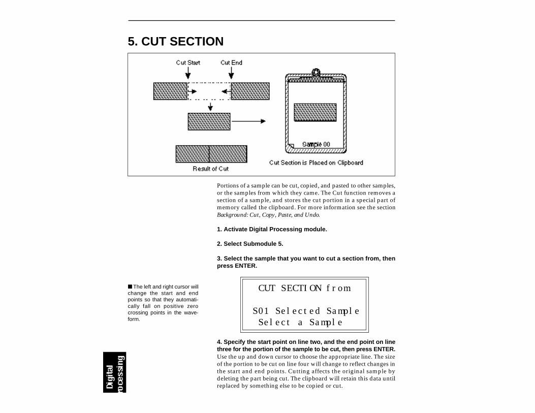
5. CUT SECTION
Portions of a sample can be cut, copied, and pasted to other samples,or the samples from which they came. The Cut function removes asection of a sample, and stores the cut portion in a special part ofmemory called the clipboard. For more information see the sectionBackground: Cut, Copy, Paste, and Undo.
1. Activate Digital Processing module.
2. Select Submodule 5.
3. Select the sample that you want to cut a section from, thenpress ENTER.
CUT SECTION from
S01 Selected Sample Select a Sample
4. Specify the start point on line two, and the end point on linethree for the portion of the sample to be cut, then press ENTER.Use the up and down cursor to choose the appropriate line. The sizeof the portion to be cut on line four will change to reflect changes inthe start and end points. Cutting affects the original sample bydeleting the part being cut. The clipboard will retain this data untilreplaced by something else to be copied or cut.
The left and right cursor willchange the start and endpoints so that they automati-cally fall on positive zerocrossing points in the wave-form.
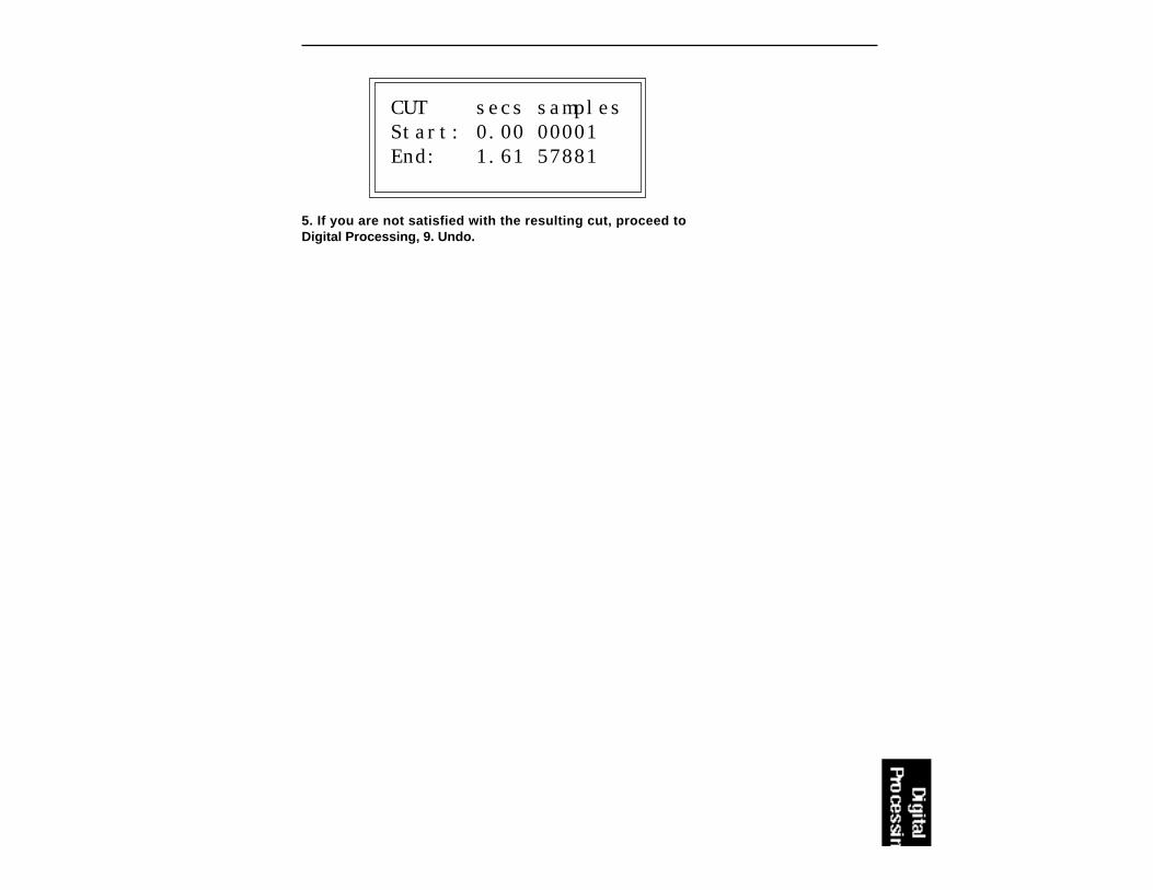
CUT secs samples Start: 0.00 00001 End: 1.61 57881
5. If you are not satisfied with the resulting cut, proceed toDigital Processing, 9. Undo.

6. PASTE SECTION
Portions of a sample can be cut, copied, and pasted to other samples,or the samples from which they came. Paste takes the clipboardcontents and either inserts them in a sample at a specified point, ormixes them with a sample starting at a specified point. For moreinformation see the section Background: Cut, Copy, Paste, and Undo.
1. Activate Digital Processing module.
2. Select Submodule 6.
3. Select the sample that you want to paste the clipboardcontents into, then press ENTER.
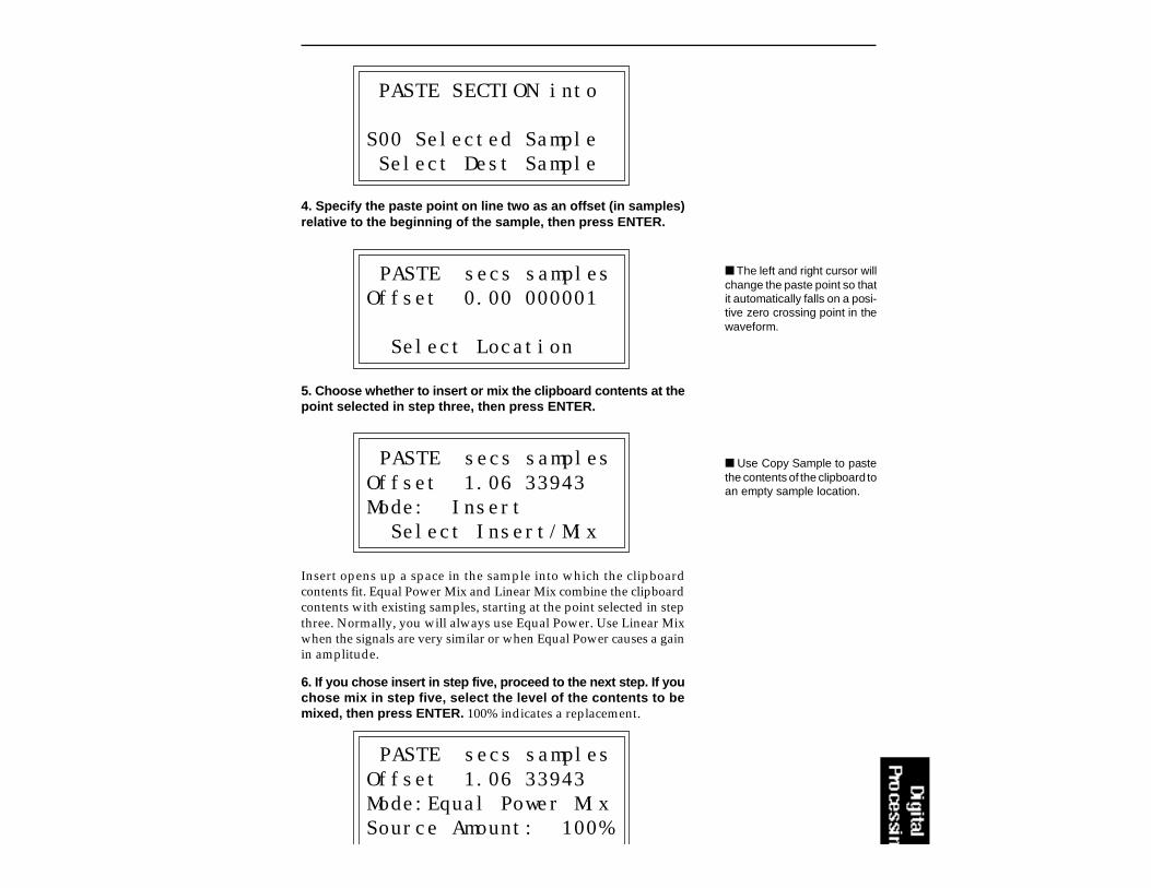
PASTE SECTION into
S00 Selected Sample Select Dest Sample
4. Specify the paste point on line two as an offset (in samples)relative to the beginning of the sample, then press ENTER.
PASTE secs samplesOffset 0.00 000001
Select Location
5. Choose whether to insert or mix the clipboard contents at thepoint selected in step three, then press ENTER.
PASTE secs samplesOffset 1.06 33943Mode: Insert Select Insert/Mix
Insert opens up a space in the sample into which the clipboardcontents fit. Equal Power Mix and Linear Mix combine the clipboardcontents with existing samples, starting at the point selected in stepthree. Normally, you will always use Equal Power. Use Linear Mixwhen the signals are very similar or when Equal Power causes a gainin amplitude.
6. If you chose insert in step five, proceed to the next step. If youchose mix in step five, select the level of the contents to bemixed, then press ENTER. 100% indicates a replacement.
PASTE secs samplesOffset 1.06 33943Mode:Equal Power MixSource Amount: 100%
The left and right cursor willchange the paste point so thatit automatically falls on a posi-tive zero crossing point in thewaveform.
Use Copy Sample to pastethe contents of the clipboard toan empty sample location.

Mixing with a source amountof 100% can be used to re-place one side of a stereosample.
7. Select the Crossfade size and type, then press ENTER.
XFADE secs samplesSize: 0.00 00000Type: Linear
Crossfading minimizes glitches from pasting dissimilar sections ofsamples. When creating time delay and flanging/chorusing effects,do not select any Xfade time for best results. Your choices are:
EqPwr: (Equal Power) This is a weighted crossfade that producesno apparent level shift. It is the most commonly used mode.
Linear: This provides a straight mathematical crossfade.
If the clipboard sample ratedoes not match that of the cur-rent sample, the EIIIX will firstchange the sample rate of theclipboard.

8. Press ENTER to perform the paste.
9. If you are not satisfied with the paste, or want to comparebefore and after, proceed to Digital Processing, 9. Undo.
This submodule contains several additional numbered functions.These are extremely useful utilities for manipulating samples. Thefollowing is a short description of each function.
0. Sample Calculator: Calculates and displays the optimum pitchto sample rate ratios for single cycle loops at the desired pitch.
1. Taper: Adds a fade-in and or fade-out to the sample, thussmoothing out samples with abrupt beginnings or endings.
2. Gain Change: Alters the level of all or a part of a sample.
3. Reverse: Reverses all or part of a sample.
4. Stereo <-> Mono: Converts a stereo sample to mono or a monosample to stereo.
5. Left <-> Right: Swaps sides if the current sample is stereo ormoves a mono sample to the other side.
6. DC Filter: Removes the DC component from a sample, center-ing the waveform around the zero axis.
7. Sample Integrity: Samples transferred from the original EIIIwill occasionally have slight looping problems. This functionquickly remedies the problem.
7. DIGITAL TOOLS I

0. Sample Calculator
1. Activate Digital Processing module.
2. Select 7. Digital Tools I, 0. Sample Calculator (7/0). The displaywill reveal the Sample Calculator.
SAMPLE CALCULATORPITCH: 440HZ A3Sample Rate: 44100HzSingle Cycle: 100.22
3. Select the pitch using either the keyboard or data slider. Thenumber of samples in a single cycle changes for each note.
4. Select sample rate on line three. Use the increment/decre-ment buttons to change the value. The number of samples in asingle cycle changes for each sample rate.
Use the Sample Calculatorto compute sample rates forperfect single cycle loops.
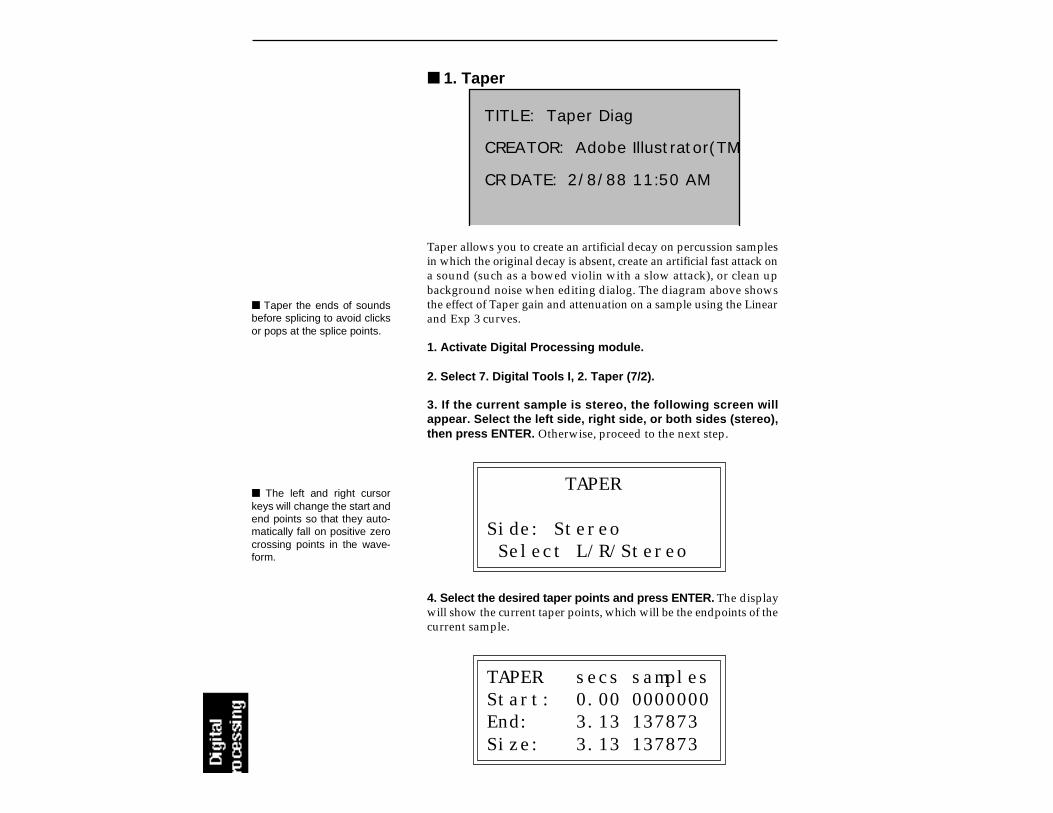
1. Taper
Taper the ends of soundsbefore splicing to avoid clicksor pops at the splice points.
TITLE: Taper Diag
CREATOR: Adobe Illustrator(TM) 1.1 M00005962N
CR DATE: 2/8/88 11:50 AM
Taper allows you to create an artificial decay on percussion samplesin which the original decay is absent, create an artificial fast attack ona sound (such as a bowed violin with a slow attack), or clean upbackground noise when editing dialog. The diagram above showsthe effect of Taper gain and attenuation on a sample using the Linearand Exp 3 curves.
1. Activate Digital Processing module.
2. Select 7. Digital Tools I, 2. Taper (7/2).
3. If the current sample is stereo, the following screen willappear. Select the left side, right side, or both sides (stereo),then press ENTER. Otherwise, proceed to the next step.
TAPER
Side: Stereo Select L/R/Stereo
4. Select the desired taper points and press ENTER. The displaywill show the current taper points, which will be the endpoints of thecurrent sample.
TAPER secs samplesStart: 0.00 0000000End: 3.13 137873Size: 3.13 137873
The left and right cursorkeys will change the start andend points so that they auto-matically fall on positive zerocrossing points in the wave-form.
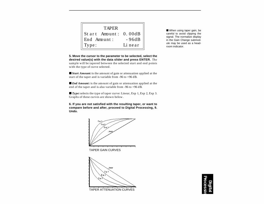
TAPERStart Amount: 0.00dBEnd Amount: -96dBType: Linear
5. Move the cursor to the parameter to be selected, select thedesired value(s) with the data slider and press ENTER. Thesample will be tapered between the selected start and end pointswith the type of curve selected.
Start Amount: is the amount of gain or attenuation applied at thestart of the taper and is variable from -96 to +96 dB.
End Amount: is the amount of gain or attenuation applied at theend of the taper and is also variable from -96 to +96 dB.
Type: selects the type of taper curve: Linear, Exp 1, Exp 2, Exp 3.Graphs of these curves are shown below.
6. If you are not satisfied with the resulting taper, or want tocompare before and after, proceed to Digital Processing, 9.Undo.
TAPER ATTENUATION CURVES
TAPER GAIN CURVES
When using taper gain, becareful to avoid clipping thesignal. The normalize displayin the Gain Change submod-ule may be used as a head-room indicator.

2. Gain ChangeGain Change alters the level of all or part of a sample.
1. Activate Digital Processing module.
2. Select 7, Digital Tools I, 2. Change Gain (7/2).
3. If the current sample is stereo, the following screen willappear. Select the left side, right side, or both sides (stereo),then press ENTER. Otherwise, proceed to the next step.
CHANGE GAIN
Side: StereoSelect L/R/Stereo
4. Select the desired gain change points and press ENTER.
GAIN secs samplesStart: 0.00 000000End: 3.13 137873Size: 3.13 137873
The display will show the current gain change points, which will bethe end points of the current sample. After pressing ENTER, theEIIIX will compute the amount of gain change necessary to achievenormalization or 0dB headroom.
5. Select the desired boost or cut with the data slider and pressENTER. The amount of boost or cut is variable from -96 dB to +96dBin 1 dB steps.
CHANGE GAIN
Amount: +00dB+04dB = Normalize
Boosting the sample gainmore than the amount speci-fied to normalize will result inclipping which may or may notbe audible. Use the normalizedisplay as a headroom indica-tor.
The left and right cursor willchange the start and endpoints so that they automati-cally fall on positive zerocrossing points in the wave-form.

Gain fade-out and fade-in using the exponential 3 curve.
6. Move the cursor to the parameter(s) to be adjusted, select thedesired value(s) with the data slider and press ENTER. Thesample will be tapered between the selected start and end pointswith the type of curve selected.
FADE secs samplesSize: 0.00 000000Type: Linear
Size: sets the size of the crossfade between gain change and no gainchange. This is variable from 0 to 1/2 the sample size.
Type: selects the type of gain curve: Linear, Exp 1, Exp 2, Exp 3.
7. If you are not satisfied with the resulting gain change, or wantto compare before and after, proceed to Digital Processing, 9.Undo.
GAIN CHANGE ATTENUATION CURVES GAIN CHANGE GAIN CURVES
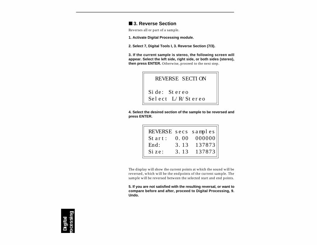
3. Reverse SectionReverses all or part of a sample.
1. Activate Digital Processing module.
2. Select 7, Digital Tools I, 3. Reverse Section (7/3).
3. If the current sample is stereo, the following screen willappear. Select the left side, right side, or both sides (stereo),then press ENTER. Otherwise, proceed to the next step.
REVERSE SECTION
Side: StereoSelect L/R/Stereo
4. Select the desired section of the sample to be reversed andpress ENTER.
REVERSE secs samplesStart: 0.00 000000End: 3.13 137873Size: 3.13 137873
The display will show the current points at which the sound will bereversed, which will be the endpoints of the current sample. Thesample will be reversed between the selected start and end points.
5. If you are not satisfied with the resulting reversal, or want tocompare before and after, proceed to Digital Processing, 9.Undo.

4. Stereo <-> MonoConverts a stereo sample to mono or a mono sample to stereo.
1. Activate Digital Processing module.
2. Select 7. Digital Tools I, 4. Stereo <-> Mono (7/4). The displaywill inquire if you want to convert the current sample to stereo (if itis mono) or to mono (if it is stereo).
STEREO <-> MONO
Convert to Mono?
3. Press YES to convert the sample to stereo or mono or NO toexit the submodule. The EIIIX will return to the Module Identifier.
5. Left <-> RightSwaps sides if the current sample is stereo or moves a mono sampleto the other side.
1. Activate Digital Processing module.
2. Select 7. Digital Tools I, 5. Swap Sides (7/5). The display willinquire if you want to swap sides if the current sample is stereo, ormove the sample to the other side if it is in mono.
SWAP SIDES
Swap Sides? Y/N
3. Press YES to swap or change sides or NO to exit thesubmodule. The EIIIX will return to the Module Identifier.
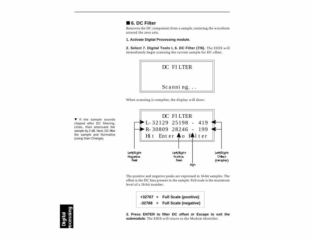
6. DC FilterRemoves the DC component from a sample, centering the waveformaround the zero axis.
1. Activate Digital Processing module.
2. Select 7. Digital Tools I, 6. DC Filter (7/6). The EIIIX willimmediately begin scanning the current sample for DC offset.
DC FILTER
Scanning...
When scanning is complete, the display will show:
DC FILTERL-32129 25198 - 419R-30809 28246 - 199Hit Enter to Filter
The positive and negative peaks are expressed in 16-bit samples. Theoffset is the DC bias present in the sample. Full scale is the maximumlevel of a 16-bit number.
+32767 = Full Scale (positive)
-32768 = Full Scale (negative)
3. Press ENTER to filter DC offset or Escape to exit thesubmodule. The EIIIX will return to the Module Identifier.
If the sample soundsclipped after DC filtering,Undo, then attenuate thesample by 2 dB. Next, DC filterthe sample and Normalize(using Gain Change).

7. Sample IntegrityBecause of the difference in pitch shifting methods betweenthe EIIIX and the original EIII, samples transferred from theoriginal EIII will occasionally have slight looping problems.This function quickly remedies the problem, fixing all sampleswithin the bank.
1. Activate Digital Processing module.
2. Select 7. Digital Tools I, 7. Sample Integrity (7/7). The displayshows:
FIX SAMPLES
Fix all samples? Y/N
3. Press ENTER to fix samples in the bank. The EIIIX will onlymodify loops which are in need of repair.

8. DIGITAL TOOLS II
This submodule contains nine more digital functions. These areextremely useful utilities for manipulating samples. Following is ashort description of each function.
1. Sample Rate Convert: Converts the sample to any sample ratebetween 7000 Hz and 50000 Hz.
2. Digital Tuning: Digitally re-tunes a sample within a range of±1 octave.
3. Compressor: The compressor dynamically changes the gain ofthe sample based on the amplitude envelope of the sample.This is a non-realtime implementation of a full featured dy-namic range compressor.
4. Parametric Equalizer: This is a digital (non real-time) imple-mentation of a one band parametric EQ, with +12 dB boost or-48 dB of cut and completely variable frequency and band-width controls.
5. Time Compression: This function changes the length of asample without changing the pitch. This can be very useful forfitting samples to the beat of a song or fitting dialog into a spot.Samples can be compressed or expanded in length from 50% to200%.
6. Pitch Change: This function changes the pitch of a samplewithout changing the time relationships between events. Themaximum amount of pitch change is ±1200 cents (± one octave).
7. Transform Multiplication: This function merges two soundstogether in a unique way which can create many strange andbeautiful sonic textures. Frequencies common to the originalsounds are accentuated while uncommon frequencies are dis-carded.
8. Doppler/Pan: This unique function allows you to dramaticallymove a sound from front to back and side to side in a 2-D space.Several pre-computed paths as well as 10 user-definable pathsare available.
9. Exciter: This function adds brilliance and “cut” to a samplehelping it to stand out in a mix. The Exciter works by addinghigh order harmonics related to the source material.
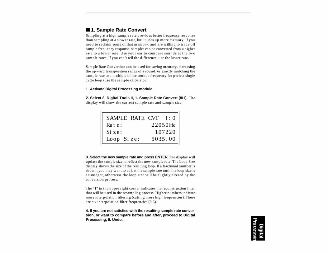
1. Sample Rate ConvertSampling at a high sample rate provides better frequency responsethan sampling at a slower rate, but it uses up more memory. If youneed to reclaim some of that memory, and are willing to trade offsample frequency response, samples can be converted from a higherrate to a lower one. Use your ear to compare sounds at the twosample rates. If you can’t tell the difference, use the lower rate.
Sample Rate Conversion can be used for saving memory, increasingthe upward transposition range of a sound, or exactly matching thesample rate to a multiple of the sounds frequency for perfect singlecycle loop (use the sample calculator).
1. Activate Digital Processing module.
2. Select 8, Digital Tools II, 1. Sample Rate Convert (8/1). Thedisplay will show the current sample rate and sample size.
SAMPLE RATE CVT f:0Rate: 22050HzSize: 107220Loop Size: 5035.00
3. Select the new sample rate and press ENTER. The display willupdate the sample size to reflect the new sample rate. The Loop Sizedisplay shows the size of the resulting loop. If a fractional number isshown, you may want to adjust the sample rate until the loop size isan integer, otherwise the loop size will be slightly altered by theconversion process.
The “f” in the upper right corner indicates the reconstruction filterthat will be used in the resampling process. Higher numbers indicatemore interpolation filtering (cutting more high frequencies). Thereare six interpolation filter frequencies (0-5).
4. If you are not satisfied with the resulting sample rate conver-sion, or want to compare before and after, proceed to DigitalProcessing, 9. Undo.
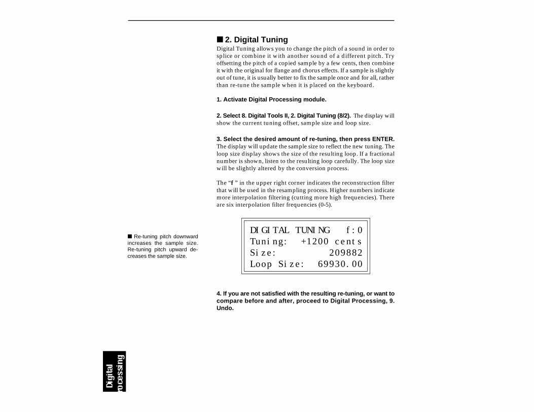
2. Digital TuningDigital Tuning allows you to change the pitch of a sound in order tosplice or combine it with another sound of a different pitch. Tryoffsetting the pitch of a copied sample by a few cents, then combineit with the original for flange and chorus effects. If a sample is slightlyout of tune, it is usually better to fix the sample once and for all, ratherthan re-tune the sample when it is placed on the keyboard.
1. Activate Digital Processing module.
2. Select 8. Digital Tools II, 2. Digital Tuning (8/2). The display willshow the current tuning offset, sample size and loop size.
3. Select the desired amount of re-tuning, then press ENTER.The display will update the sample size to reflect the new tuning. Theloop size display shows the size of the resulting loop. If a fractionalnumber is shown, listen to the resulting loop carefully. The loop sizewill be slightly altered by the conversion process.
The “f ” in the upper right corner indicates the reconstruction filterthat will be used in the resampling process. Higher numbers indicatemore interpolation filtering (cutting more high frequencies). Thereare six interpolation filter frequencies (0-5).
DIGITAL TUNING f:0Tuning: +1200 centsSize: 209882Loop Size: 69930.00
4. If you are not satisfied with the resulting re-tuning, or want tocompare before and after, proceed to Digital Processing, 9.Undo.
Re-tuning pitch downwardincreases the sample size.Re-tuning pitch upward de-creases the sample size.

3. Digital CompressorThe Digital Compressor is a digital (non-realtime) equivalent of ananalog dynamic range compressor with attack and release times,adjustable threshold, adjustable ratio, and three modes of operation.
1. Activate Digital Processing module.
2. Select 8. Digital Tools II, 3. Digital Compressor (8/3).
3. If the current sample is stereo, the following screen willappear. Select the left side, right side, or both sides (stereo),then press Enter. Otherwise proceed to the next step.
DIGITAL COMPRESSOR
Side: Stereo Select L/R/Stereo
4. Select the desired area to be compressed and press ENTER.
COMPRESSsecs samplesStart: 0.00 000000End: 3.13 137873Size: 3.13 137873
The display will show the current points of the sample to be com-pressed, which will be the start and end points of the current sample.Select the section of the sample to be compressed, then press ENTER.
COMPRESSOR Mode: rmsThres: center 100%Ratio: 4.00:1Atk:999ms Rel:999ms
5. Position the cursor under the desired parameter and adjustthe value using the data slider.
Note: The gain setting whichis in effect at the end point ofthe selected section will re-main in effect for the rest of thesample. This is done to pre-vent nasty pops and phaseproblems caused by an abrupttransition back to the normalgain.

Only signal levels below thethreshold % will be affectedby the compressor.
Signal levels above as wellas below the threshold %will be affected by thecompressor.
Only signal levels abovethe threshold % will beaffected by the compressor.

Mode: RMS or Peak.
RMS = root-mean-square or an “average of the magni-tude of the signal”. RMS represents the “true”energy content of a signal.
Peak = Uses the peak amplitude of a signal to determinethe amplitude. The peak amplitude is a meaning-ful measurement in a digital system because ofthe 96db (16-bit) headroom limit.
Threshold: Above, Center, Below, %
Above = Only signal levels above the threshold % will beaffected by the compressor.
Center =Signal levels above as well as below the threshold% will be affected by the compressor.
Below = Only signal levels below the threshold % will beaffected by the compressor.
% = Determines the threshold level as a percentage of100% of 16-bits.
Compression Ratio: Variable from 0.01 : 1 to 99.8 : 1.
Determines the amount of compression or expansion.Ratios of greater than 1:1 compress dynamic range. Ratiosof less than 1:1 expand dynamic range.
Compression: Reduces the amount of dynamic range.Levels remain more constant.
Expansion: Expands the amount of dynamic range.Changes in level are exaggerated.
Attack Time: Determines how quickly the gain will be turneddown. The attack time is variable from 0 to 999milliseconds.
Release Time: Determines how quickly the gain will be turnedup. The release time is variable from 0 to 999milliseconds.

Using the Digital Compressor
Limiter - A limiter prevents the signal from exceeding a presetlevel (threshold). Signal levels below the threshold will beunaffected.
Set the controls as follows:Threshold: Above, XX% (where XX is the limit point).
Ratio: >10:1
Attack Time: 1 mS
Release Time: approximately 100 mS
Musical Compression (i.e. Guitar) - This type of compressiontries to keep the volume constant, generally to increase the sustain ofthe instrument. As the note dies away, the compressor will boost thelevel in an effort to keep the level constant.
Set the controls as follows:Threshold: Center, XX% (where XX is the compression point).
Ratio: approximately 4:1
Attack Time: 1 mS to 100 mS
Release Time: > 100 mS
Noise Reduction - Noise reduction will reduce low levels evenfurther in the assumption that low levels are noise.
Set the controls as follows:Threshold: Below, approx. 30%
Ratio: approximately 0.7:1
Attack Time: approximately 100 mS
Release Time: approximately 100 mS

4. Parametric EqualizerParametric EQ allows you adjust the individual parameters of thefilter. Boost and Cut controls “how much” of the signal will beboosted or cut. Center Frequency sets the center frequency to beboosted or cut, and the Bandwidth control sets the width of the bandto be boosted or cut. The three parameters are diagrammed below.
The parametric equalizer is a digital (non real-time) equivalent of ananalog equalizer with +12 db of boost and a whopping -48 dB of cut.Accurate center frequency and bandwidth controls are similarlyprecise and exceptionally wide range.
1. Activate Digital Processing module.
2. Select 8. Digital Tools II, 4. Parametric EQ (8/4).
3. If the current sample is stereo, the following screen willappear. Select the left side, right side, or both sides (stereo),then press ENTER. Otherwise proceed to the next step.
PARAMETRIC EQ
Side: Stereo Select L/R/Stereo
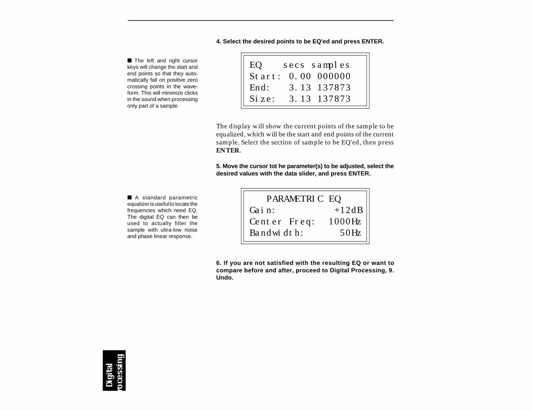
4. Select the desired points to be EQ'ed and press ENTER.
EQ secs samplesStart: 0.00 000000End: 3.13 137873Size: 3.13 137873
The display will show the current points of the sample to beequalized, which will be the start and end points of the currentsample. Select the section of sample to be EQ'ed, then pressENTER.
5. Move the cursor tot he parameter(s) to be adjusted, select thedesired values with the data slider, and press ENTER.
PARAMETRIC EQGain: +12dBCenter Freq: 1000HzBandwidth: 50Hz
6. If you are not satisfied with the resulting EQ or want tocompare before and after, proceed to Digital Processing, 9.Undo.
The left and right cursorkeys will change the start andend points so that they auto-matically fall on positive zerocrossing points in the wave-form. This will minimize clicksin the sound when processingonly part of a sample.
A standard parametricequalizer is useful to locate thefrequencies which need EQ.The digital EQ can then beused to actually filter thesample with ultra-low noiseand phase linear response.
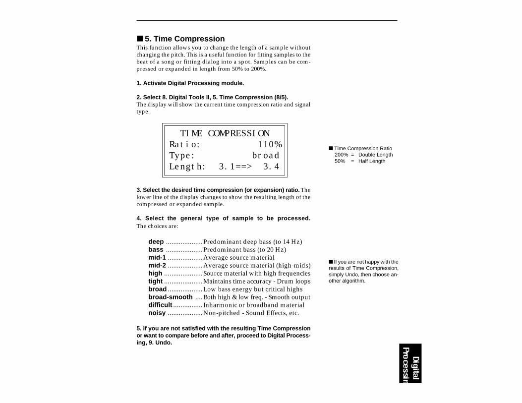
5. Time CompressionThis function allows you to change the length of a sample withoutchanging the pitch. This is a useful function for fitting samples to thebeat of a song or fitting dialog into a spot. Samples can be com-pressed or expanded in length from 50% to 200%.
1. Activate Digital Processing module.
2. Select 8. Digital Tools II, 5. Time Compression (8/5).The display will show the current time compression ratio and signaltype.
TIME COMPRESSIONRatio: 110%Type: broadLength: 3.1==> 3.4
3. Select the desired time compression (or expansion) ratio. Thelower line of the display changes to show the resulting length of thecompressed or expanded sample.
4. Select the general type of sample to be processed.The choices are:
deep ....................Predominant deep bass (to 14 Hz)bass ....................Predominant bass (to 20 Hz)mid-1 ...................Average source materialmid-2 ...................Average source material (high-mids)high .....................Source material with high frequenciestight .....................Maintains time accuracy - Drum loopsbroad ...................Low bass energy but critical highsbroad-smooth ....Both high & low freq. - Smooth outputdifficult ................ Inharmonic or broadband materialnoisy ...................Non-pitched - Sound Effects, etc.
5. If you are not satisfied with the resulting Time Compressionor want to compare before and after, proceed to Digital Process-ing, 9. Undo.
Time Compression Ratio200% = Double Length50% = Half Length
If you are not happy with theresults of Time Compression,simply Undo, then choose an-other algorithm.

6. Pitch ChangeThis function is the exact opposite of Time Compression in that itchanges the pitch of a sample without changing the time. Themaximum amount of pitch change is ±1200 cents (± one octave).
1. Activate Digital Processing module.
2. Select 8. Digital Tools II, 6. Pitch Change (8/6).The display will show the current amount of pitch change in cents(1/100 of a semitone) and signal type.
PITCH CHANGETune: + 52ctsType: mid-2
3. Select the desired pitch change amount. The lower line of thedisplay changes to show the resulting length of the compressed orexpanded sample.
4. Select the general type of sample to be processed.The choices are:
deep ....................Predominant deep bass (to 14 Hz)bass ....................Predominant bass (to 20 Hz)mid-1 ...................Average source materialmid-2 ...................Average source material (high-mids)high .....................Source material with high frequenciestight .....................Maintains time accuracy - Drum loopsbroad ...................Low bass energy but critical highsbroad-smooth ....Both high & low freq. - Smooth outputdifficult ................ Inharmonic or broadband materialnoisy ...................Non-pitched - Sound Effects, etc.
5. If you are not satisfied with the resulting Pitch Change or wantto compare before and after, proceed to Digital Processing, 9.Undo.

7. Transform MultiplicationThis function merges two sounds together in a way that frequenciescommon to both sounds are accentuated while uncommonfrequencies are discarded. Because of this characteristic, TransformMultiplication tends to work best with sounds that are harmonicallyrich. The length of the resulting sample will be equal to that of thecurrent sample.
1. Activate Digital Processing module.
2. Select Submodule 0 (Select Sample).
3. Select the first source sample to be multiplied, then pressEnter.
4. Select 8. Digital Tools II, 7. Transform Multiplication (8/7).The display will shows:
TRANSFORM MULTIPLY072 Flute C4L 0.1secs 29312HzSelect Second Sample
5. Select the second sample to be multiplied using the inc/decbuttons, the data slider or the keypad. The third line of the displayshows the characteristics of the second sample (L, R, or L/R), thelength and the sample rate.
6. Press ENTER to select the second sample.The display shows the time required to process the samples.
TRANSFORM MULTIPLY
Will take 26 mins.. Continue? Y/N
7. Press Yes to start the computation or No to return to theModule Identifier.
Transform Multiplicationcan take quite a bit of time withlonger samples. Begin yourexperiments with shortsamples or even attacks asthese give good initial results.
Transform MultiplicationIdeas
• Try using the same sound forboth samples.
• Splicing silence to the begin-nings or ends of short samplescan change the spectral char-acteristics of the result.
• Using speech as one of thesources, it is possible to“speak from within” violins,bassoons, cymbals etc.
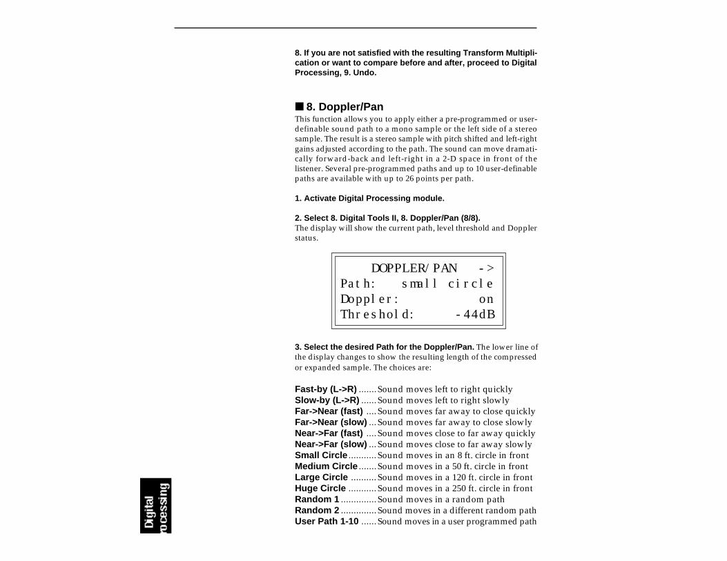
8. If you are not satisfied with the resulting Transform Multipli-cation or want to compare before and after, proceed to DigitalProcessing, 9. Undo.
8. Doppler/PanThis function allows you to apply either a pre-programmed or user-definable sound path to a mono sample or the left side of a stereosample. The result is a stereo sample with pitch shifted and left-rightgains adjusted according to the path. The sound can move dramati-cally forward-back and left-right in a 2-D space in front of thelistener. Several pre-programmed paths and up to 10 user-definablepaths are available with up to 26 points per path.
1. Activate Digital Processing module.
2. Select 8. Digital Tools II, 8. Doppler/Pan (8/8).The display will show the current path, level threshold and Dopplerstatus.
DOPPLER/PAN ->Path: small circleDoppler: onThreshold: -44dB
3. Select the desired Path for the Doppler/Pan. The lower line ofthe display changes to show the resulting length of the compressedor expanded sample. The choices are:
Fast-by (L->R) .......Sound moves left to right quicklySlow-by (L->R) ......Sound moves left to right slowlyFar->Near (fast) ....Sound moves far away to close quicklyFar->Near (slow) ...Sound moves far away to close slowlyNear->Far (fast) ....Sound moves close to far away quicklyNear->Far (slow) ...Sound moves close to far away slowlySmall Circle ...........Sound moves in an 8 ft. circle in frontMedium Circle .......Sound moves in a 50 ft. circle in frontLarge Circle ..........Sound moves in a 120 ft. circle in frontHuge Circle ...........Sound moves in a 250 ft. circle in frontRandom 1 ..............Sound moves in a random pathRandom 2 ..............Sound moves in a different random pathUser Path 1-10 ......Sound moves in a user programmed path
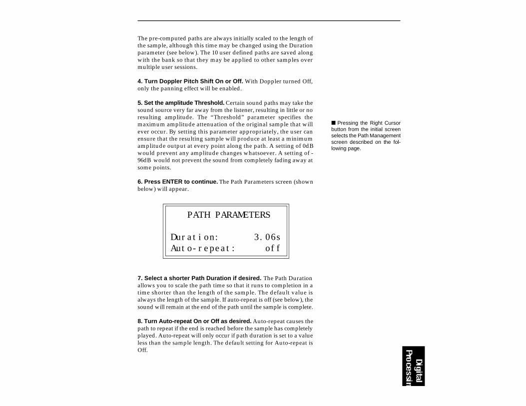
The pre-computed paths are always initially scaled to the length ofthe sample, although this time may be changed using the Durationparameter (see below). The 10 user defined paths are saved alongwith the bank so that they may be applied to other samples overmultiple user sessions.
4. Turn Doppler Pitch Shift On or Off. With Doppler turned Off,only the panning effect will be enabled.
5. Set the amplitude Threshold. Certain sound paths may take thesound source very far away from the listener, resulting in little or noresulting amplitude. The “Threshold” parameter specifies themaximum amplitude attenuation of the original sample that willever occur. By setting this parameter appropriately, the user canensure that the resulting sample will produce at least a minimumamplitude output at every point along the path. A setting of 0dBwould prevent any amplitude changes whatsoever. A setting of -96dB would not prevent the sound from completely fading away atsome points.
6. Press ENTER to continue. The Path Parameters screen (shownbelow) will appear.
PATH PARAMETERS
Duration: 3.06sAuto-repeat: off
7. Select a shorter Path Duration if desired. The Path Durationallows you to scale the path time so that it runs to completion in atime shorter than the length of the sample. The default value isalways the length of the sample. If auto-repeat is off (see below), thesound will remain at the end of the path until the sample is complete.
8. Turn Auto-repeat On or Off as desired. Auto-repeat causes thepath to repeat if the end is reached before the sample has completelyplayed. Auto-repeat will only occur if path duration is set to a valueless than the sample length. The default setting for Auto-repeat isOff.
Pressing the Right Cursorbutton from the initial screenselects the Path Managementscreen described on the fol-lowing page.

9. Press ENTER to begin processing the sample. The displayshows:
Doppler/Pan
Processing path...
10. If you are not satisfied with the resulting Doppler/Pan or wantto compare before and after, proceed to Digital Processing, 9.Undo.
PATH MANAGEMENT SCREEN
Sound paths may optionally be edited and processed in a number ofways. If the right cursor is pressed in the initial Doppler/Pan screen,the Path Manager screen appears:
<- PATH MANAGER
Path: user path 1Function: reverse
The path may be selected in this screen as well. “Function” specifiesthe path processing function. The available functions are:
edit .............edit a user path
copy ...........copy a path into one of the user paths
reverse .......cause a user path to be played in reverse
flip ...............flip a user path around the X-axis
offset ..........apply an x and/or y offset to a user path
clear ...........initialize a user path
The pre-programmed paths must first be copied to a user locationbefore they can be edited.
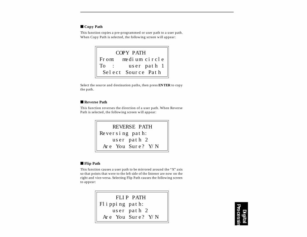
Copy Path
This function copies a pre-programmed or user path to a user path.When Copy Path is selected, the following screen will appear:
COPY PATHFrom: medium circleTo : user path 1 Select Source Path
Select the source and destination paths, then press ENTER to copythe path.
Reverse Path
This function reverses the direction of a user path. When ReversePath is selected, the following screen will appear:
REVERSE PATHReversing path: user path 2 Are You Sure? Y/N
Flip Path
This function causes a user path to be mirrored around the “X” axisso that points that were to the left side of the listener are now on theright and vice-versa. Selecting Flip Path causes the following screento appear:
FLIP PATHFlipping path: user path 2 Are You Sure? Y/N
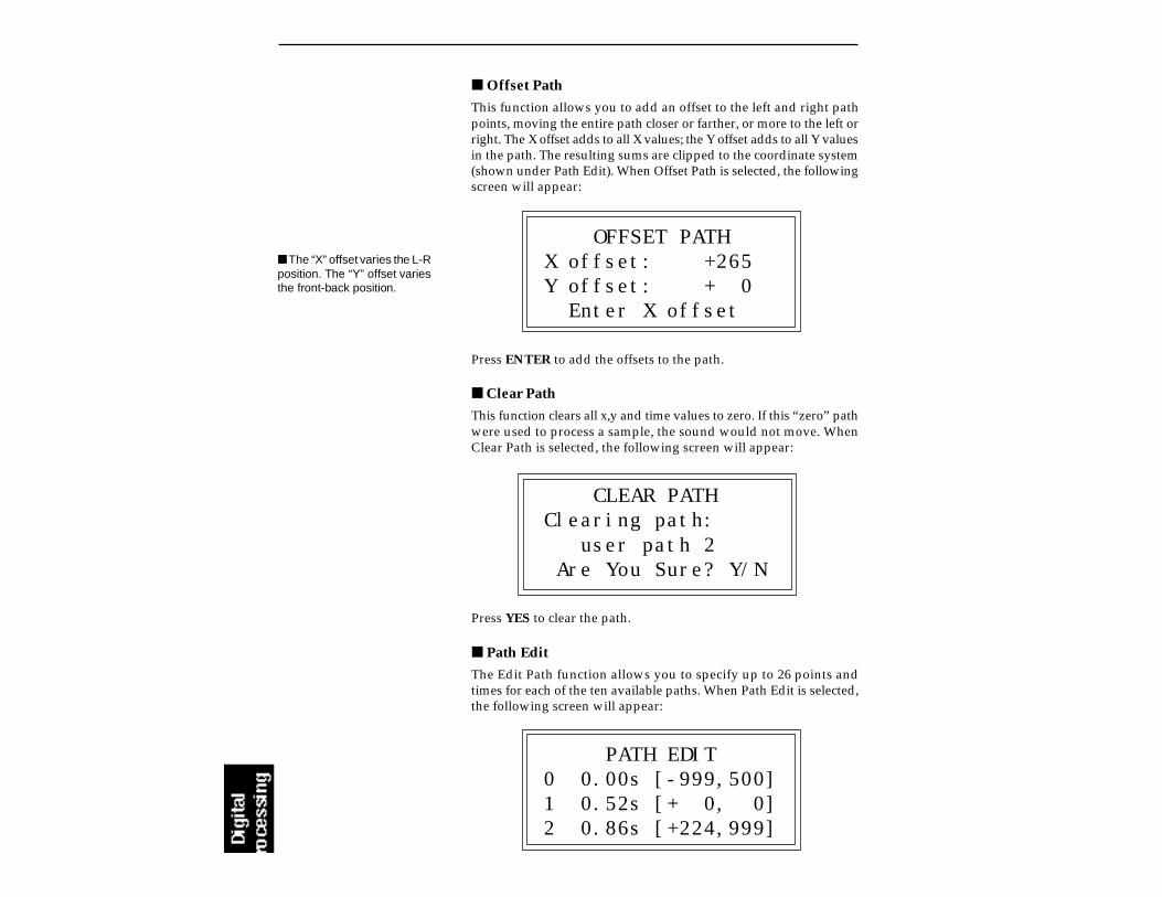
Offset Path
This function allows you to add an offset to the left and right pathpoints, moving the entire path closer or farther, or more to the left orright. The X offset adds to all X values; the Y offset adds to all Y valuesin the path. The resulting sums are clipped to the coordinate system(shown under Path Edit). When Offset Path is selected, the followingscreen will appear:
OFFSET PATHX offset: +265Y offset: + 0 Enter X offset
Press ENTER to add the offsets to the path.
Clear Path
This function clears all x,y and time values to zero. If this “zero” pathwere used to process a sample, the sound would not move. WhenClear Path is selected, the following screen will appear:
CLEAR PATHClearing path: user path 2 Are You Sure? Y/N
Press YES to clear the path.
Path Edit
The Edit Path function allows you to specify up to 26 points andtimes for each of the ten available paths. When Path Edit is selected,the following screen will appear:
PATH EDIT0 0.00s [-999,500]1 0.52s [+ 0, 0]2 0.86s [+224,999]
The “X” offset varies the L-Rposition. The “Y” offset variesthe front-back position.
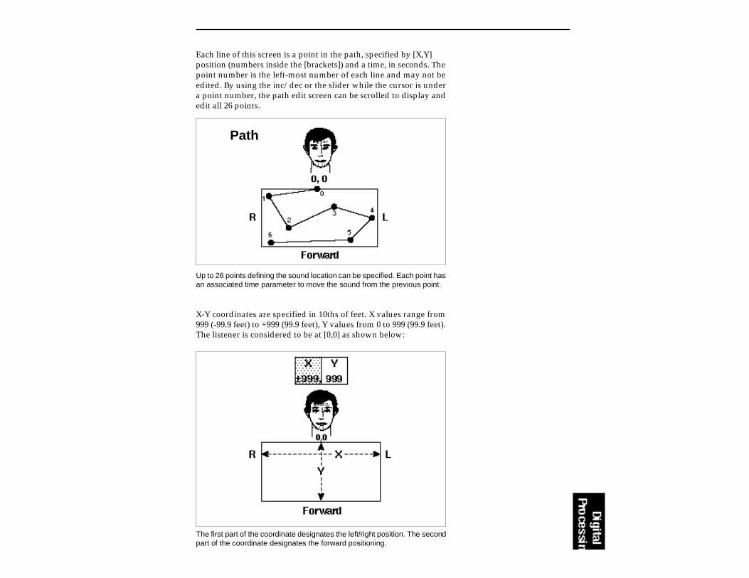
Each line of this screen is a point in the path, specified by [X,Y]position (numbers inside the [brackets]) and a time, in seconds. Thepoint number is the left-most number of each line and may not beedited. By using the inc/dec or the slider while the cursor is undera point number, the path edit screen can be scrolled to display andedit all 26 points.
Up to 26 points defining the sound location can be specified. Each point hasan associated time parameter to move the sound from the previous point.
Path
X-Y coordinates are specified in 10ths of feet. X values range from999 (-99.9 feet) to +999 (99.9 feet), Y values from 0 to 999 (99.9 feet).The listener is considered to be at [0,0] as shown below:
The first part of the coordinate designates the left/right position. The secondpart of the coordinate designates the forward positioning.

The diagram above shows the extreme positions of the path coordinates.
Time values range from 0 to the length of the current sample. Notethat if this path is applied to a different sample, all time values will bescaled to the length of the different sample.
Once path editing is complete, press ENTER to return to the PathManagement screen. When the path is ready to apply to the sample,press the left cursor button while in the Path Management screen toreturn to the main Doppler/Pan screen. Press ENTER again to moveahead to the Path Parameters screen and once more to process thesample.
9. ExciterThis function adds brilliance and “cut” to a sample making it standout in a mix. The effect is especially effective on vocal samples towhich it adds sheen, clarity and presence. The Exciter works bygenerating new harmonics related to the source material. Anysection of a sample can be processed, and the exciter effect can beprogrammably faded in and out.
1. Activate Digital Processing module.
2. Select 8. Digital Tools II, 9. Doppler/Pan (8/9).
3. If the current sample is stereo, the following screen willappear. Select the left side, right side, or both sides (stereo),then press ENTER. Otherwise, proceed to the next step

EXCITER
Side: StereoSelect L/RStereo
4. Select the desired points in the sample and press ENTER. Thedisplay will show the current points to be processed, which will bethe endpoints of the current sample.
EXCITER secs samplesStart: 0.00 00000End: 2.95 35421Size: 2.95 35421
5. Move the cursor to the parameter to be selected, select thedesired value(s) with the data slider and press ENTER. Thesample will be processed with the exciter effect between the selectedstart and end points and with the selected fade-in/fade-out times.
EXCITERAmount: 018%Tune: 5FadeIn:000 Out:000ms
Amount .............. The intensity of the effect. (Lower values (<40%)work well as they keep the effect subtle.)
Tune ................... The frequency range of the effect. Higher numberemphasize higher frequencies.
Fade In ............... The length of time for an effect to fade-in fromzero to “Amount”.
Fade Out ............ The length of time for an effect to fade-out from“Amount” to zero.

6. If you are not satisfied with the resulting Excitation or want tocompare before and after, proceed to Digital Processing, 9.Undo.
Using the Digital Exciter
Attack (only) Processing - Set the Start Point to 0, and the EndPoint to some small value (≈ .15 secs) to match the attack time of thesample. Set the Fade-in to 0 and the Fade-out to match the End Pointvalue (≈.15 secs). The attack portion of the sample will have fullexcitation which fades out during the attack.
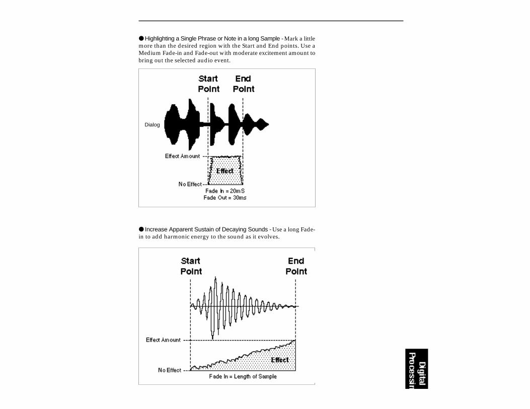
Highlighting a Single Phrase or Note in a long Sample - Mark a littlemore than the desired region with the Start and End points. Use aMedium Fade-in and Fade-out with moderate excitement amount tobring out the selected audio event.
Increase Apparent Sustain of Decaying Sounds - Use a long Fade-in to add harmonic energy to the sound as it evolves.
Dialog
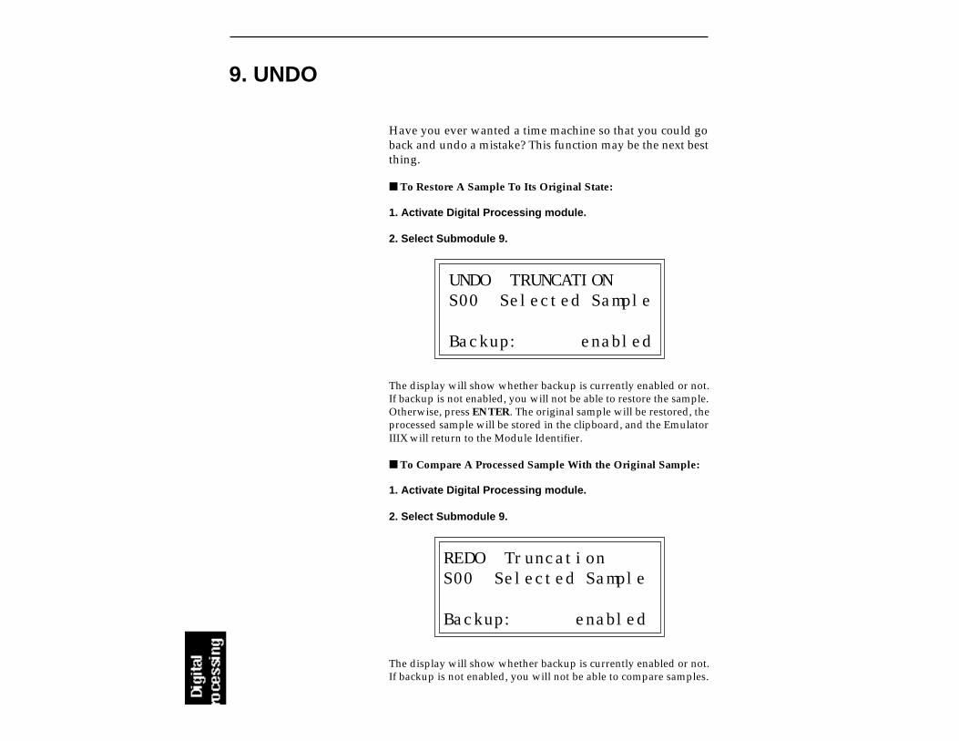
Have you ever wanted a time machine so that you could goback and undo a mistake? This function may be the next bestthing.
To Restore A Sample To Its Original State:
1. Activate Digital Processing module.
2. Select Submodule 9.
UNDO TRUNCATIONS00 Selected Sample
Backup: enabled
The display will show whether backup is currently enabled or not.If backup is not enabled, you will not be able to restore the sample.Otherwise, press ENTER. The original sample will be restored, theprocessed sample will be stored in the clipboard, and the EmulatorIIIX will return to the Module Identifier.
To Compare A Processed Sample With the Original Sample:
1. Activate Digital Processing module.
2. Select Submodule 9.
REDO TruncationS00 Selected Sample
Backup: enabled
The display will show whether backup is currently enabled or not.If backup is not enabled, you will not be able to compare samples.
9. UNDO
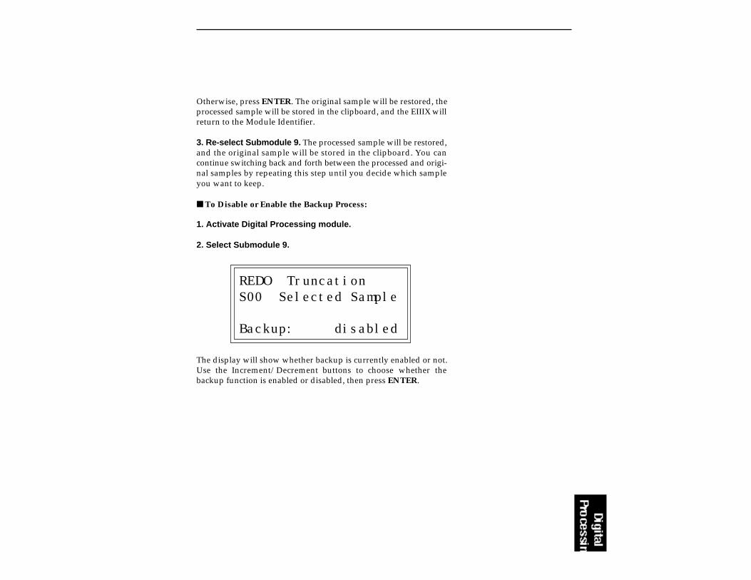
Otherwise, press ENTER. The original sample will be restored, theprocessed sample will be stored in the clipboard, and the EIIIX willreturn to the Module Identifier.
3. Re-select Submodule 9. The processed sample will be restored,and the original sample will be stored in the clipboard. You cancontinue switching back and forth between the processed and origi-nal samples by repeating this step until you decide which sampleyou want to keep.
To Disable or Enable the Backup Process:
1. Activate Digital Processing module.
2. Select Submodule 9.
REDO TruncationS00 Selected Sample
Backup: disabled
The display will show whether backup is currently enabled or not.Use the Increment/Decrement buttons to choose whether thebackup function is enabled or disabled, then press ENTER.


6-PRESET MANAGEMENT
1. LOAD PRESET 6-2
2. RENAME PRESET 6-4
3. ERASE PRESET 6-5
4. COPY PRESET 6-6
5. CREATE PRESET 6-7
6. PRESET SIZE 6-8
7. STACK MODE 6-9
8. VELOCITY SWITCH 6-10LEVEL
9. MERGE PRESETS 6-11
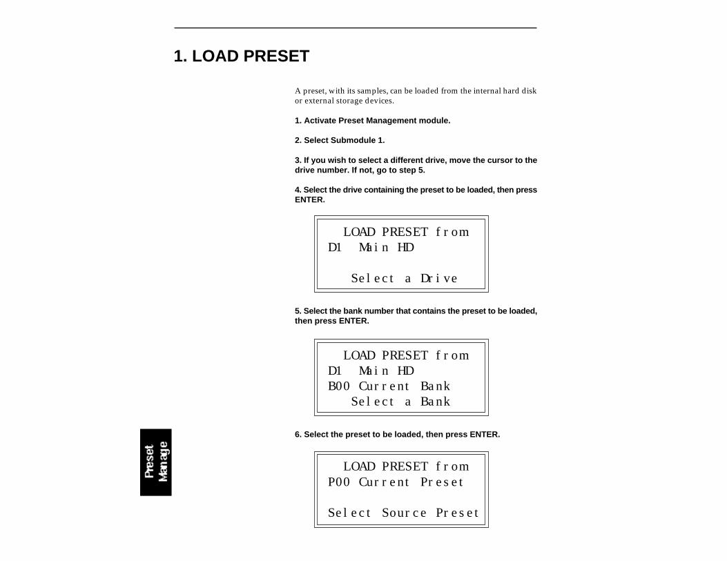
1. LOAD PRESET
A preset, with its samples, can be loaded from the internal hard diskor external storage devices.
1. Activate Preset Management module.
2. Select Submodule 1.
3. If you wish to select a different drive, move the cursor to thedrive number. If not, go to step 5.
4. Select the drive containing the preset to be loaded, then pressENTER.
LOAD PRESET fromD1 Main HD
Select a Drive
5. Select the bank number that contains the preset to be loaded,then press ENTER.
LOAD PRESET fromD1 Main HDB00 Current Bank Select a Bank
6. Select the preset to be loaded, then press ENTER.
LOAD PRESET fromP00 Current Preset
Select Source Preset
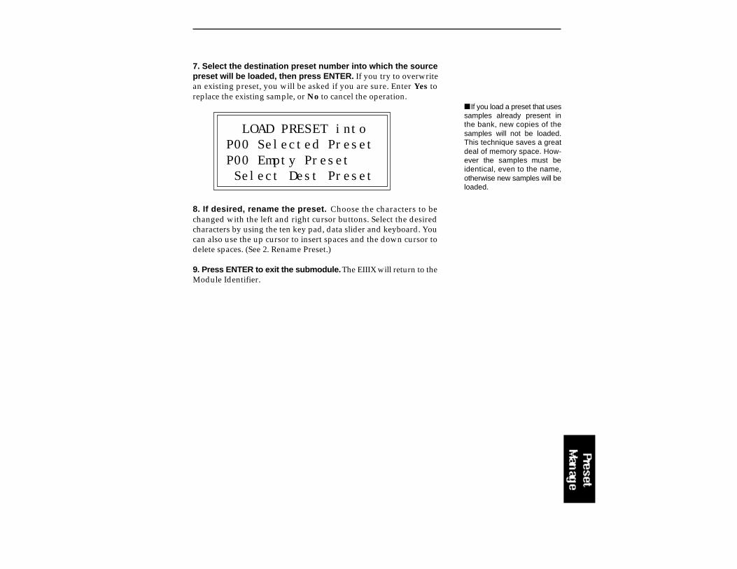
If you load a preset that usessamples already present inthe bank, new copies of thesamples will not be loaded.This technique saves a greatdeal of memory space. How-ever the samples must beidentical, even to the name,otherwise new samples will beloaded.
7. Select the destination preset number into which the sourcepreset will be loaded, then press ENTER. If you try to overwritean existing preset, you will be asked if you are sure. Enter Yes toreplace the existing sample, or No to cancel the operation.
LOAD PRESET intoP00 Selected PresetP00 Empty Preset Select Dest Preset
8. If desired, rename the preset. Choose the characters to bechanged with the left and right cursor buttons. Select the desiredcharacters by using the ten key pad, data slider and keyboard. Youcan also use the up cursor to insert spaces and the down cursor todelete spaces. (See 2. Rename Preset.)
9. Press ENTER to exit the submodule. The EIIIX will return to theModule Identifier.
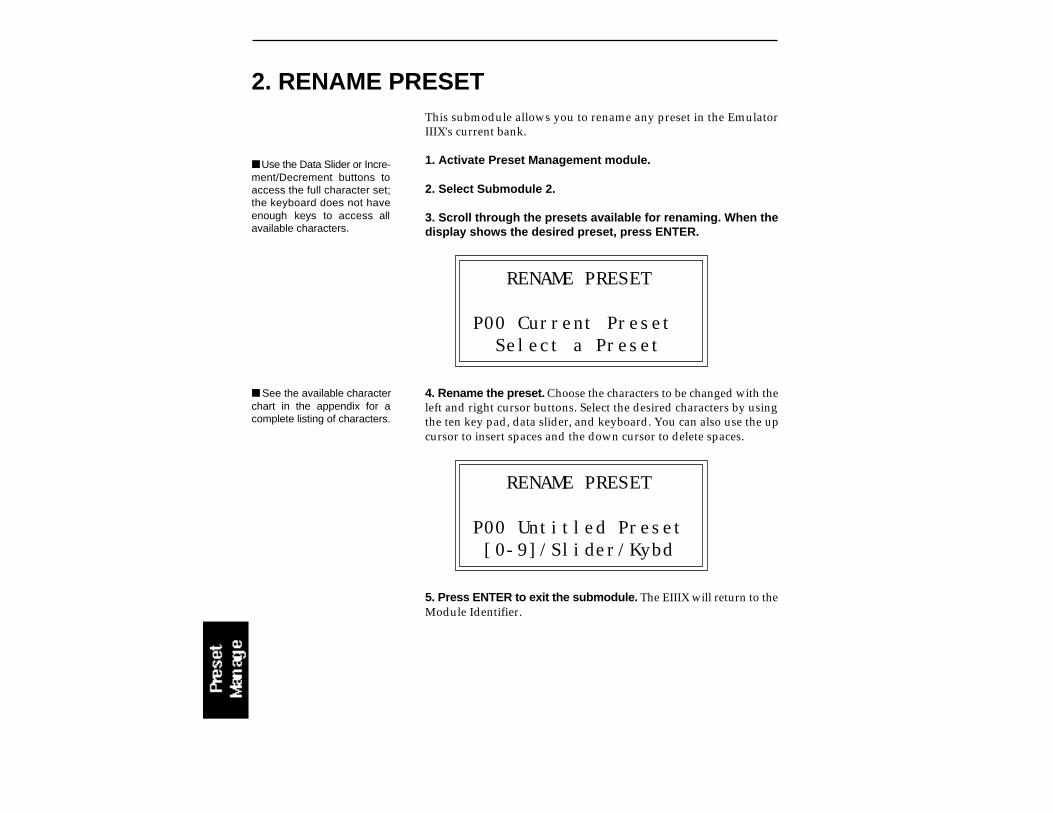
2. RENAME PRESET
Use the Data Slider or Incre-ment/Decrement buttons toaccess the full character set;the keyboard does not haveenough keys to access allavailable characters.
This submodule allows you to rename any preset in the EmulatorIIIX's current bank.
1. Activate Preset Management module.
2. Select Submodule 2.
3. Scroll through the presets available for renaming. When thedisplay shows the desired preset, press ENTER.
RENAME PRESET
P00 Current Preset Select a Preset
4. Rename the preset. Choose the characters to be changed with theleft and right cursor buttons. Select the desired characters by usingthe ten key pad, data slider, and keyboard. You can also use the upcursor to insert spaces and the down cursor to delete spaces.
RENAME PRESET
P00 Untitled Preset [0-9]/Slider/Kybd
5. Press ENTER to exit the submodule. The EIIIX will return to theModule Identifier.
See the available characterchart in the appendix for acomplete listing of characters.
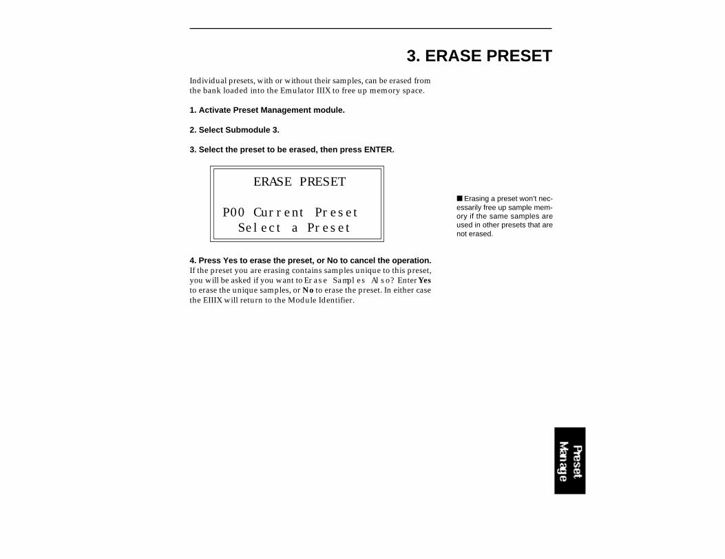
3. ERASE PRESETIndividual presets, with or without their samples, can be erased fromthe bank loaded into the Emulator IIIX to free up memory space.
1. Activate Preset Management module.
2. Select Submodule 3.
3. Select the preset to be erased, then press ENTER.
ERASE PRESET
P00 Current Preset Select a Preset
4. Press Yes to erase the preset, or No to cancel the operation.If the preset you are erasing contains samples unique to this preset,you will be asked if you want to Erase Samples Also? Enter Yesto erase the unique samples, or No to erase the preset. In either casethe EIIIX will return to the Module Identifier.
Erasing a preset won’t nec-essarily free up sample mem-ory if the same samples areused in other presets that arenot erased.

4. COPY PRESET
Copying a preset will notmake copies of the samplesused in the preset.
Presets can be copied to other preset numbers within the same bank.This is useful if you want to create variations on a particular preset.For example, you may want to alter the MIDI, velocity, or arpeggia-tor setups, or Dynamic Processing parameters.
1. Activate Preset Management module.
2. Select Submodule 4.
3. Select the preset to be copied, then press ENTER.
COPY PRESET fromP00 Current Preset
Select Source Preset
4. Select the destination preset number into which the sourcepreset will be copied, then press ENTER. If you try to overwritean existing preset, you will be asked if you want to overwrite. PressYes to replace the existing sample, or No to cancel the operation.
COPY PRESET intoP00 Selected PresetP01 Empty PresetSelect Dest Preset
5. If desired, rename the preset. Choose the characters to bechanged with the left and right cursor buttons. Select the desiredcharacters by using the ten key pad, data slider and keyboard. Youcan also use the up cursor to insert spaces and the down cursor todelete spaces.
6. Press ENTER to exit the submodule. The EIIIX will return to theModule Identifier.
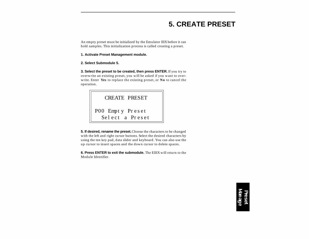
5. CREATE PRESET
An empty preset must be initialized by the Emulator IIIX before it canhold samples. This initialization process is called creating a preset.
1. Activate Preset Management module.
2. Select Submodule 5.
3. Select the preset to be created, then press ENTER. If you try tooverwrite an existing preset, you will be asked if you want to over-write. Enter Yes to replace the existing preset, or No to cancel theoperation.
CREATE PRESET
P00 Empty Preset Select a Preset
5. If desired, rename the preset. Choose the characters to be changedwith the left and right cursor buttons. Select the desired characters byusing the ten key pad, data slider and keyboard. You can also use theup cursor to insert spaces and the down cursor to delete spaces.
6. Press ENTER to exit the submodule. The EIIIX will return to theModule Identifier.
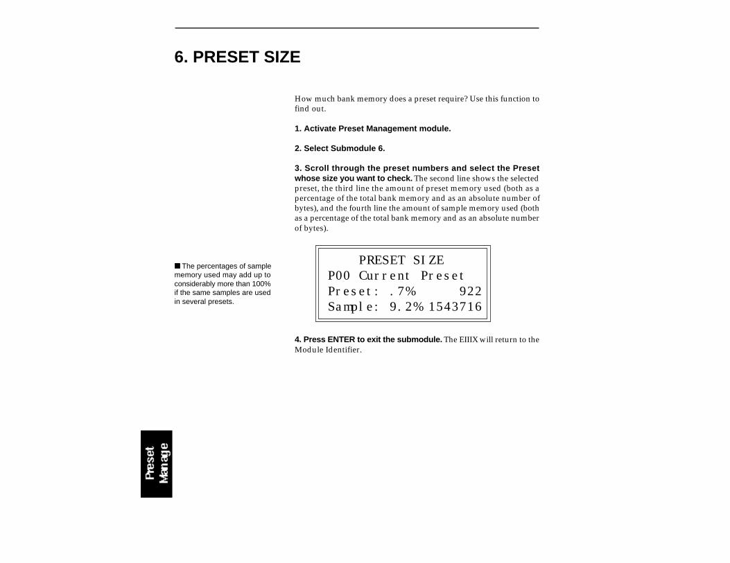
6. PRESET SIZE
The percentages of samplememory used may add up toconsiderably more than 100%if the same samples are usedin several presets.
How much bank memory does a preset require? Use this function tofind out.
1. Activate Preset Management module.
2. Select Submodule 6.
3. Scroll through the preset numbers and select the Presetwhose size you want to check. The second line shows the selectedpreset, the third line the amount of preset memory used (both as apercentage of the total bank memory and as an absolute number ofbytes), and the fourth line the amount of sample memory used (bothas a percentage of the total bank memory and as an absolute numberof bytes).
PRESET SIZEP00 Current PresetPreset: .7% 922Sample: 9.2% 1543716
4. Press ENTER to exit the submodule. The EIIIX will return to theModule Identifier.
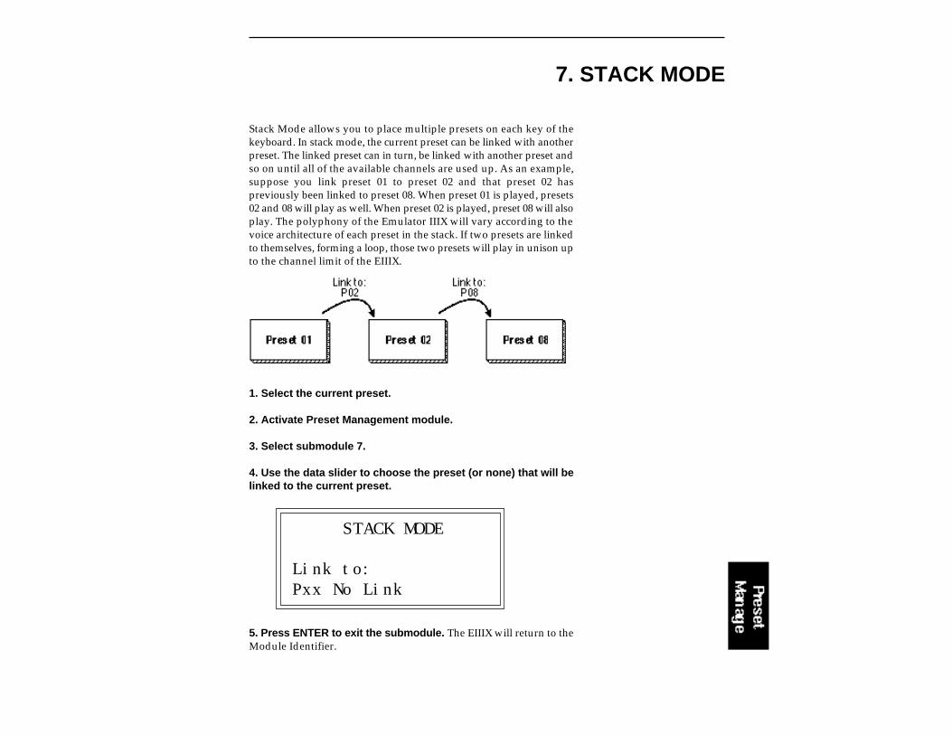
7. STACK MODE
Stack Mode allows you to place multiple presets on each key of thekeyboard. In stack mode, the current preset can be linked with anotherpreset. The linked preset can in turn, be linked with another preset andso on until all of the available channels are used up. As an example,suppose you link preset 01 to preset 02 and that preset 02 haspreviously been linked to preset 08. When preset 01 is played, presets02 and 08 will play as well. When preset 02 is played, preset 08 will alsoplay. The polyphony of the Emulator IIIX will vary according to thevoice architecture of each preset in the stack. If two presets are linkedto themselves, forming a loop, those two presets will play in unison upto the channel limit of the EIIIX.
1. Select the current preset.
2. Activate Preset Management module.
3. Select submodule 7.
4. Use the data slider to choose the preset (or none) that will belinked to the current preset.
STACK MODE
Link to:Pxx No Link
5. Press ENTER to exit the submodule. The EIIIX will return to theModule Identifier.

The velocity cross-switch function in the Preset Definition module,(5. Crossfade/Switch) allows overlapping samples to be switchedaccording to key velocity. This function sets the velocity at whichsamples are cross-switched.
1. Activate Preset Management module.
2. Select submodule 8.
3. Use the data slider to select the velocity at which samples willbe cross-switched. Velocity values range from one to 127.
VEL SWITCH LEVEL
Level: 64
4. Press ENTER to exit the submodule. The EIIIX will return to theModule Identifier.
8. VELOCITY SWITCH LEVEL
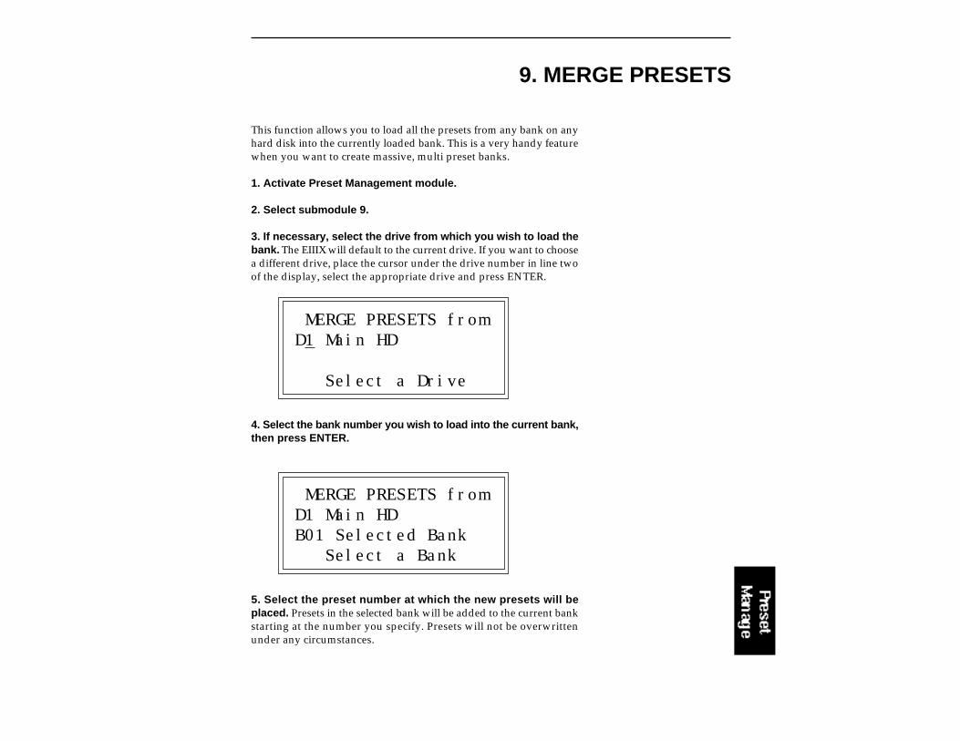
9. MERGE PRESETS
This function allows you to load all the presets from any bank on anyhard disk into the currently loaded bank. This is a very handy featurewhen you want to create massive, multi preset banks.
1. Activate Preset Management module.
2. Select submodule 9.
3. If necessary, select the drive from which you wish to load thebank. The EIIIX will default to the current drive. If you want to choosea different drive, place the cursor under the drive number in line twoof the display, select the appropriate drive and press ENTER.
MERGE PRESETS fromD1 Main HD
Select a Drive
4. Select the bank number you wish to load into the current bank,then press ENTER.
MERGE PRESETS fromD1 Main HDB01 Selected Bank Select a Bank
5. Select the preset number at which the new presets will beplaced. Presets in the selected bank will be added to the current bankstarting at the number you specify. Presets will not be overwrittenunder any circumstances.
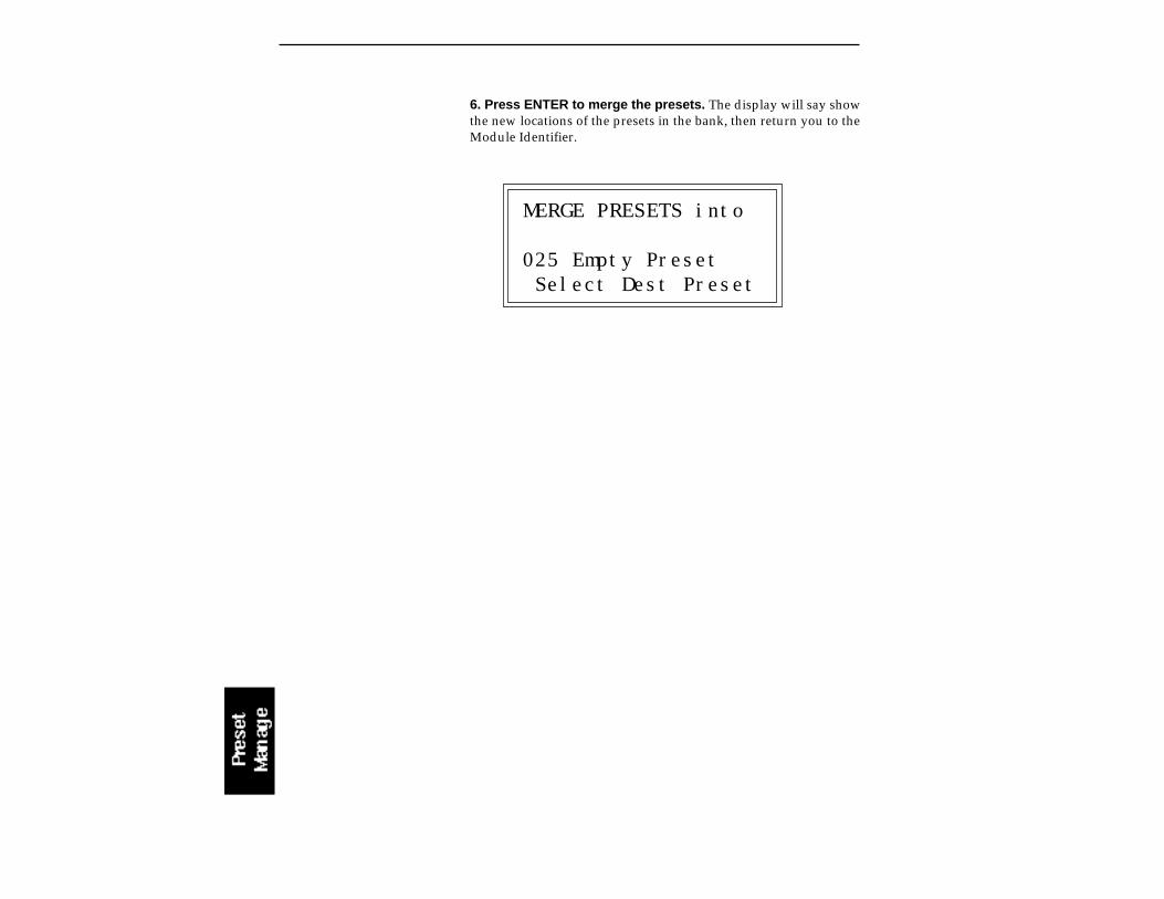
6. Press ENTER to merge the presets. The display will say showthe new locations of the presets in the bank, then return you to theModule Identifier.
MERGE PRESETS into
025 Empty Preset Select Dest Preset


9-DYNAMIC PROCESSING
BACKGROUND 9-2
0. SELECT ZONE 9-4
1. SETUP 9-6
2. VCA 9-8
3. VCF 9-10
4. LFO 9-13
5. AUXILIARY 9-15ENVELOPE
6. VELOCITY TO 9-17
7. KEYBOARD MODE 9-20
8. REALTIME 9-22CONTROL ENABLE
9. OUTPUT 9-23CHANNELS
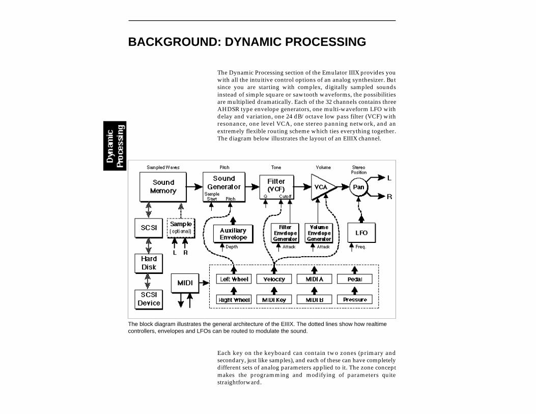
BACKGROUND: DYNAMIC PROCESSING
The Dynamic Processing section of the Emulator IIIX provides youwith all the intuitive control options of an analog synthesizer. Butsince you are starting with complex, digitally sampled soundsinstead of simple square or sawtooth waveforms, the possibilitiesare multiplied dramatically. Each of the 32 channels contains threeAHDSR type envelope generators, one multi-waveform LFO withdelay and variation, one 24 dB/octave low pass filter (VCF) withresonance, one level VCA, one stereo panning network, and anextremely flexible routing scheme which ties everything together.The diagram below illustrates the layout of an EIIIX channel.
Each key on the keyboard can contain two zones (primary andsecondary, just like samples), and each of these can have completelydifferent sets of analog parameters applied to it. The zone conceptmakes the programming and modifying of parameters quitestraightforward.
The block diagram illustrates the general architecture of the EIIIX. The dotted lines show how realtimecontrollers, envelopes and LFOs can be routed to modulate the sound.
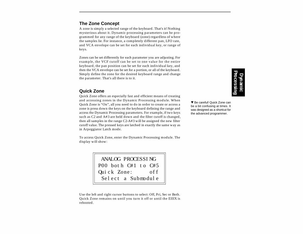
The Zone ConceptA zone is simply a selected range of the keyboard. That's it! Nothingmysterious about it. Dynamic processing parameters can be pro-grammed for any range of the keyboard (zone) regardless of wherethe samples lie. For instance, a completely different pan, LFO rate,and VCA envelope can be set for each individual key, or range ofkeys.
Zones can be set differently for each parameter you are adjusting. Forexample, the VCF cutoff can be set to one value for the entirekeyboard, the pan position can be set for each individual key, andthen the VCA envelope can be set for a portion, or all of the keyboard.Simply define the zone for the desired keyboard range and changethe parameter. That's all there is to it.
Quick ZoneQuick Zone offers an especially fast and efficient means of creatingand accessing zones in the Dynamic Processing module. WhenQuick Zone is “On”, all you need to do in order to create or access azone is press down the keys on the keyboard defining the range andaccess the Dynamic Processing parameters. For example, if two keyssuch as C2 and A#3 are held down and the filter cutoff is changed,then all samples in the range C2-A#3 will be assigned the new filtercutoff value. The pressed keys are latched in exactly the same way asin Arpeggiator Latch mode.
To access Quick Zone, enter the Dynamic Processing module. Thedisplay will show:
ANALOG PROCESSINGP00 both C#1 to C#5Quick Zone: off Select a Submodule
Use the left and right cursor buttons to select: Off, Pri, Sec or Both.Quick Zone remains on until you turn it off or until the EIIIX isrebooted.
Be careful! Quick Zone canbe a bit confusing at times. Itwas designed as a shortcut forthe advanced programmer.
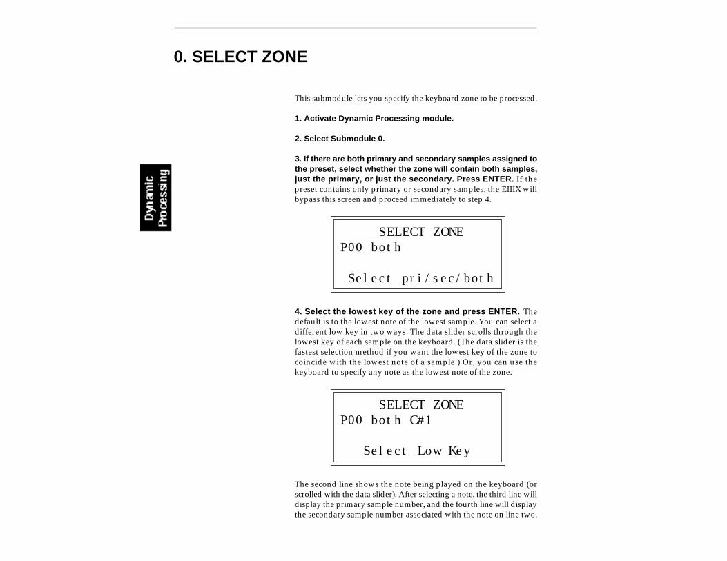
This submodule lets you specify the keyboard zone to be processed.
1. Activate Dynamic Processing module.
2. Select Submodule 0.
3. If there are both primary and secondary samples assigned tothe preset, select whether the zone will contain both samples,just the primary, or just the secondary. Press ENTER. If thepreset contains only primary or secondary samples, the EIIIX willbypass this screen and proceed immediately to step 4.
SELECT ZONEP00 both
Select pri/sec/both
4. Select the lowest key of the zone and press ENTER. Thedefault is to the lowest note of the lowest sample. You can select adifferent low key in two ways. The data slider scrolls through thelowest key of each sample on the keyboard. (The data slider is thefastest selection method if you want the lowest key of the zone tocoincide with the lowest note of a sample.) Or, you can use thekeyboard to specify any note as the lowest note of the zone.
SELECT ZONEP00 both C#1
Select Low Key
The second line shows the note being played on the keyboard (orscrolled with the data slider). After selecting a note, the third line willdisplay the primary sample number, and the fourth line will displaythe secondary sample number associated with the note on line two.
0. SELECT ZONE

5. Select the highest key of the zone and press ENTER. Thedefault is to the highest note of the sample that contains the previ-ously specified low note. You can select a different high key in twoways. The data slider scrolls through the highest key of each sampleon the keyboard. (The data slider is the fastest selection method ifyou want the highest key of the zone to coincide with the highest noteof a sample.) Or, you can use the keyboard to specify any note as thehighest note of the zone.
SELECT ZONEP00 both C#1 to C#5
Select High Key
The second line shows the note being played on the keyboard (orscrolled with the data slider). After selecting a note, the third line willdisplay the primary sample number, and the fourth line will displaythe secondary sample number associated with the note on line two.After pressing ENTER, the zone selection process is complete andthe EIIIX will return to the Module Identifier.
If there are no samples in theselected zone, the EIIIX willreturn to the beginning of thezone selection process. Thezone will remain as specifieduntil you either select a newzone, change presets, loadanother bank, or edit the as-signment of the keyboard.
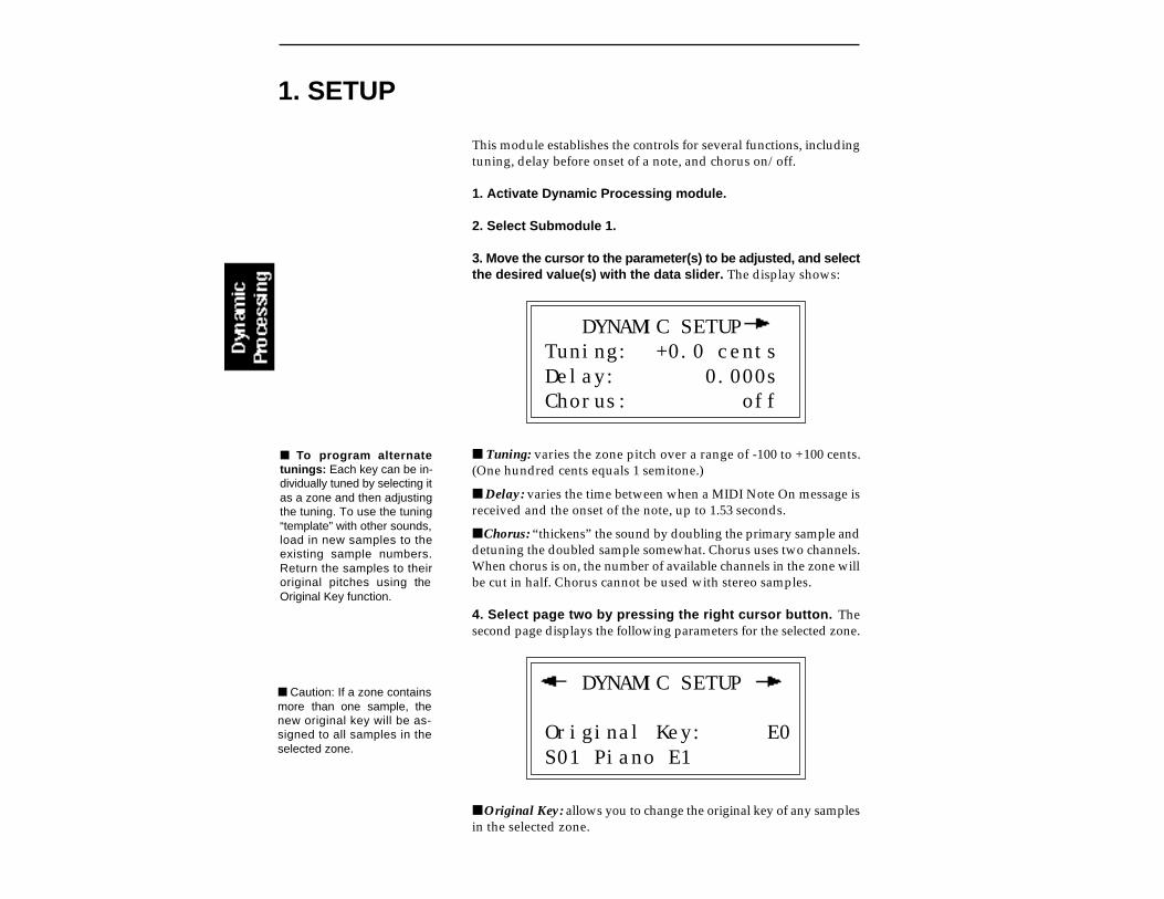
1. SETUP
This module establishes the controls for several functions, includingtuning, delay before onset of a note, and chorus on/off.
1. Activate Dynamic Processing module.
2. Select Submodule 1.
3. Move the cursor to the parameter(s) to be adjusted, and selectthe desired value(s) with the data slider. The display shows:
DYNAMIC SETUPTuning: +0.0 centsDelay: 0.000sChorus: off
Tuning: varies the zone pitch over a range of -100 to +100 cents.(One hundred cents equals 1 semitone.)
Delay: varies the time between when a MIDI Note On message isreceived and the onset of the note, up to 1.53 seconds.
Chorus: “thickens” the sound by doubling the primary sample anddetuning the doubled sample somewhat. Chorus uses two channels.When chorus is on, the number of available channels in the zone willbe cut in half. Chorus cannot be used with stereo samples.
4. Select page two by pressing the right cursor button. Thesecond page displays the following parameters for the selected zone.
DYNAMIC SETUP
Original Key: E0S01 Piano E1
Original Key: allows you to change the original key of any samplesin the selected zone.
Caution: If a zone containsmore than one sample, thenew original key will be as-signed to all samples in theselected zone.
To program alternatetunings: Each key can be in-dividually tuned by selecting itas a zone and then adjustingthe tuning. To use the tuning“template” with other sounds,load in new samples to theexisting sample numbers.Return the samples to theiroriginal pitches using theOriginal Key function.

Change Sample Number: allows you to reassign any sample in thebank to the selected zone.
5. Select page three by pressing the right cursor button. Thethird page displays the following parameters for the selected zone.
DYNAMIC SETUP
Disable Loop: offDisable Side: off
Disable Loop: turns off the loop for any samples within theselected zone for the current preset and overrides any loop settingsmade in the Digital Processing module for the current preset.
Disable Side: turns off playback of either the left or right side ofa stereo sample within the selected zone.
6. Press ENTER to exit the submodule. The EIIIX will return to theModule Identifier.
Caution: If a zone containsmore than one sample, thenew sample will overwrite theprevious sample assignment.

2. VCA
The Voltage-Controlled Amplifier (VCA) submodule contains twopages. Page one sets the overall zone level and stereo placement(pan). Page two sets the AHDSR envelope characteristics that alterVCA dynamics with respect to time.
1. Activate Dynamic Processing module.
2. Select Submodule 2.
3. Move the cursor to the parameter(s) to be adjusted, and selectthe desired value(s) with the data slider. The first page reads:
VCALevel: 100%Pan: +000%L | R
Level: is variable from 0 to 100%.
Pan: is continuously variable from +100, where the zone appearsat the right extreme of the stereo image; through 0, where the zoneappears at the center of the stereo image; to -100, where the zoneappears at the left extreme of the stereo image. The display graphi-cally indicates the stereo position on the bottom line. The initialplacement may have to be adjusted as modulation is applied to pan.
4. Select page two by pressing the right cursor button. Thesecond page displays the following parameters for the VCA AHDSRenvelope generator:
VCA Attack: 0.00sHold: 0.00sDecay: 0.00sSus:100% Rel: 1.04s
Refer to the following diagrams and definitions to understand howeach parameter affects dynamics.
When VCA Level is set to100%, additional modulationfrom pedals, LFOs, etc., willnot increase the level. Youmust reduce the VCA levelfrom the 100% mark for addi-tional modulation to have anyeffect.
The stereo placement mayadditionally be modulated viathe LFO (Dynamic Process-ing, 4. LFO), keyboard dynam-ics (Dynamic Processing, 6.Velocity to Pan) or realtimecontrols (Preset Definition, 0.Realtime Controls). The ac-tual stereo position will be thesum of the initial placementsand any modulations.
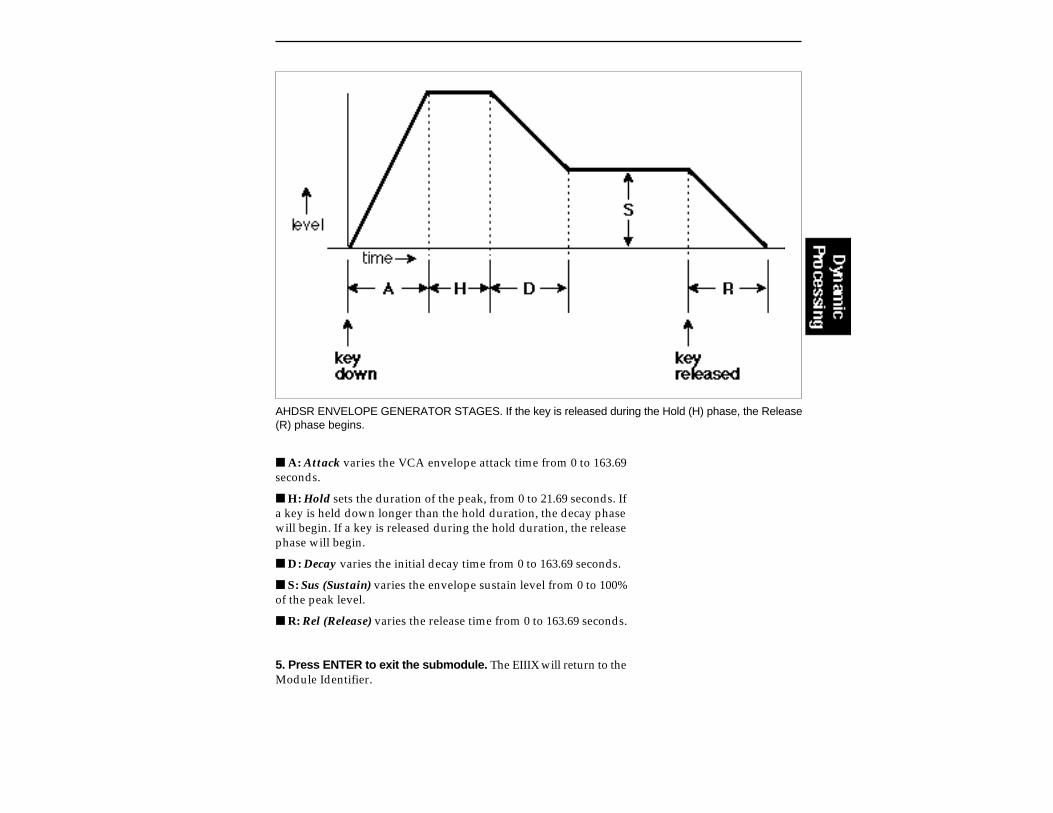
AHDSR ENVELOPE GENERATOR STAGES. If the key is released during the Hold (H) phase, the Release(R) phase begins.
A: Attack varies the VCA envelope attack time from 0 to 163.69seconds.
H: Hold sets the duration of the peak, from 0 to 21.69 seconds. Ifa key is held down longer than the hold duration, the decay phasewill begin. If a key is released during the hold duration, the releasephase will begin.
D: Decay varies the initial decay time from 0 to 163.69 seconds.
S: Sus (Sustain) varies the envelope sustain level from 0 to 100%of the peak level.
R: Rel (Release) varies the release time from 0 to 163.69 seconds.
5. Press ENTER to exit the submodule. The EIIIX will return to theModule Identifier.

3. VCF
The Voltage-Controlled Filter (VCF) submodule contains threepages. Page one determines the filter’s initial cutoff frequency and Q(resonance). Page two determines the effect of keyboard position oncutoff frequency, and the extent to which the associated AHDSRenvelope affects the filter cutoff frequency (envelope amount). Pagethree sets the VCF AHDSR envelope characteristics. These altertimbre with respect to time.
1. Activate Dynamic Processing module.
2. Select Submodule 3.
3. Move the cursor to the parameter(s) to be adjusted, and selectthe desired value(s) with the data slider. The first page reveals:
VCF
Cutoff: 22049HzQ: 0%
VCF Cutoff: varies the lowpass filter cutoff from 0 Hz to 22049Hz.Higher values correspond to higher filter cutoff frequencies, hencea sound with more treble. The maximum filter sweep range is mostobvious with envelope amount set to +0.
Q: varies the resonance from 0 to 100%. Higher values correspondto increased resonance, which accentuates the frequency response atthe filter cutoff frequency. This produces a sharper, more whistlingsound.
4. Select page two by pressing the right cursor button. Thesecond page shows:
VCF
Tracking: +1.00Envelope Amt: + 0%

KEYBOARD TRACKING. This varies the filter cutoff with respect to the notes being played.
Tracking: varies the filter cutoff with respect to the note(s) beingplayed on the keyboard from -2.00 to +2.00. With 0.00 tracking, thefilter cutoff will not be affected by the keyboard pitch. With trackingset to -2.00, the filter cutoff will increase at one-quarter the rate atwhich pitch increases. With tracking set to +2.00, the filter cutoff willincrease at twice the rate at which pitch increases. Intermediatevalues give intermediate degrees of tracking. With negative track-ing, a sample will become progressively less bright as you playhigher up in the zone. This is useful with some bass sounds, and toeven out frequency response variations between samples whenmulti-sampling. With 0.00 tracking, a sample’s timbre remains con-stant over the selected zone. This generally gives the most realisticsynthesizer and instrument sounds. With positive tracking, thesample’s timbre becomes brighter as you play higher up in the zone.
Envelope Amt: varies the effect of the filter envelope on the filtercutoff frequency from -100, which is the maximum inverted enve-lope, through +00, which has no effect from the envelope, to +100,which is the maximum positive envelope. It is usually necessary toraise the filter cutoff value when using inverted envelopes.
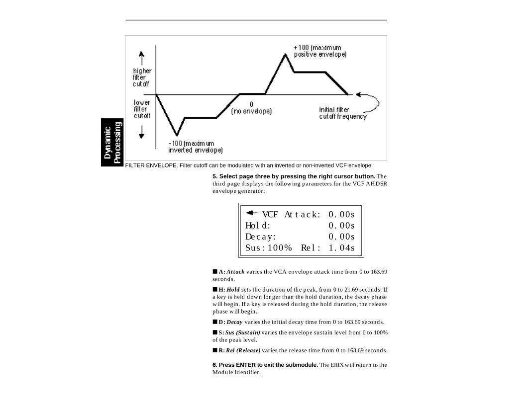
FILTER ENVELOPE. Filter cutoff can be modulated with an inverted or non-inverted VCF envelope.
5. Select page three by pressing the right cursor button. Thethird page displays the following parameters for the VCF AHDSRenvelope generator:
VCF Attack: 0.00sHold: 0.00sDecay: 0.00sSus:100% Rel: 1.04s
A: Attack varies the VCA envelope attack time from 0 to 163.69seconds.
H: Hold sets the duration of the peak, from 0 to 21.69 seconds. Ifa key is held down longer than the hold duration, the decay phasewill begin. If a key is released during the hold duration, the releasephase will begin.
D: Decay varies the initial decay time from 0 to 163.69 seconds.
S: Sus (Sustain) varies the envelope sustain level from 0 to 100%of the peak level.
R: Rel (Release) varies the release time from 0 to 163.69 seconds.
6. Press ENTER to exit the submodule. The EIIIX will return to theModule Identifier.

4. LFO
The Low-Frequency Oscillator (LFO) submodule contains threepages. Page one sets the LFO rate, the shape of the LFO waveform,and the delay before onset of modulation. Pages two and threedetermine the degree to which the rate will be varied as you playdifferent notes (LFO variation), the LFO’s destination(s): pitch(which produces vibrato), the VCF cutoff, the VCA amplitude (pro-duces tremolo—attention surf music and Bo Diddley fans), andpanning (spatial modulation). The amount of modulation (index)sent to each destination is variable from 0 to 100%.
1. Activate Dynamic Processing module.
2. Select Submodule 4.
3. Move the cursor to the parameter(s) to be adjusted, and selectthe desired value(s) with the data slider. The first page shows:
LFORate: 4.25HzShape: triangleDelay: 0.00s
LFO Rate: varies the LFO speed from 0.08 Hz to 18.14 Hz.
LFO Shape: selects the waveshape of the LFO. The available LFOwaveforms are: triangle, sine, sawtooth and square.
LFO Delay: sets the amount of time between hitting a key and theonset of modulation. This simulates an effect often used by stringplayers, where the vibrato is brought in only after the initial notepitch has been clearly established. The delay range is from 0 to 21.69seconds.
4. Select page two by pressing the right cursor button. Thesecond page shows:
LFOVariation: 0%LFO->Pitch: 0%LFO->Cutoff: 0%

LFO Variation: provides a way to create the illusion of multipleplayers, each having an individual modulation rate. The depth ofLFO modulation applied to each parameter is variable from 0 to100%. With 0% variation, each key will have the same LFO rate.Increasing variation (to a maximum of 100%) alters the LFO rate foreach key you play. The higher the number, the greater the variationin LFO rate. For effects such as ensemble playing, the variationfeature is invaluable.
LFO —>Pitch: produces vibrato effects.
LFO —>Cutoff: varies the VCF’s cutoff frequency in a cyclicfashion. This is useful for adding shimmering effects to a sound.
5. Select page three by pressing the right cursor button. Thethird page displays the following LFO routing options:
LFO
LFO->VCA: 0%LFO->Pan: 0%
LFO —> VCA: produces tremolo effects by altering the overalllevel of a zone in a cyclic fashion.
LFO —> Pan: cyclically varies the placement of the audio outputof a zone within the stereo field.
6. Press ENTER to exit the submodule. The EIIIX will return to theModule Identifier.
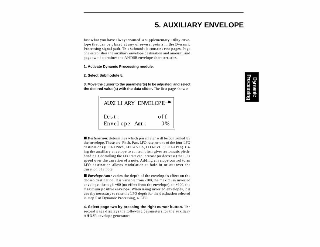
5. AUXILIARY ENVELOPE
Just what you have always wanted: a supplementary utility enve-lope that can be placed at any of several points in the DynamicProcessing signal path. This submodule contains two pages. Pageone establishes the auxiliary envelope destination and amount, andpage two determines the AHDSR envelope characteristics.
1. Activate Dynamic Processing module.
2. Select Submodule 5.
3. Move the cursor to the parameter(s) to be adjusted, and selectthe desired value(s) with the data slider. The first page shows:
AUXILIARY ENVELOPE
Dest: offEnvelope Amt: 0%
Destination: determines which parameter will be controlled bythe envelope. These are: Pitch, Pan, LFO rate, or one of the four LFOdestinations (LFO->Pitch, LFO->VCA, LFO->VCF, LFO->Pan). Us-ing the auxiliary envelope to control pitch gives automatic pitch-bending. Controlling the LFO rate can increase (or decrease) the LFOspeed over the duration of a note. Adding envelope control to anLFO destination allows modulation to fade in or out over theduration of a note.
Envelope Amt: varies the depth of the envelope’s effect on thechosen destination. It is variable from -100, the maximum invertedenvelope, through +00 (no effect from the envelope), to +100, themaximum positive envelope. When using inverted envelopes, it isusually necessary to raise the LFO depth for the destination selectedin step 5 of Dynamic Processing, 4. LFO.
4. Select page two by pressing the right cursor button. Thesecond page displays the following parameters for the auxiliaryAHDSR envelope generator:

AHDSR ENVELOPE GENERATOR STAGES. If the key is releasedduring the Hold (H) phase, the Release (R) phase begins.
Aux Attack: 0.00sHold: 0.00sDecay: 0.00sSus:100% Rel: 1.04s
Refer to the definitions below to understand how each parameteraffects the envelope.
A: Attack varies the VCA envelope attack time from 0 to 163.69seconds.
H: Hold sets the duration of the peak, from 0 to 21.69 seconds. Ifa key is held down longer than the hold duration, the decay phasewill begin. If a key is released during the hold duration, the releasephase will begin.
D: Decay varies the initial decay time from 0 to 163.69 seconds.
S: Sus (Sustain) varies the envelope sustain level from 0 to 100%of the peak level.
R: Rel (Release) varies the release time from 0 to 163.69 seconds.
5. Press ENTER to exit the submodule. The EIIIX will return to theModule Identifier.

6. VELOCITY TO
Velocity data from your MIDI keyboard, sequencer or other control-ler can control any or all of nine different parameters, as selected onthree pages in this submodule.
1. Activate Dynamic Processing module.
2. Select Submodule 6.
3. Move the cursor to the parameter(s) to be adjusted, and selectthe desired value(s) with the data slider. The first page shows:
VELOCITY TO:Pitch: +0%VCA Level: +0%VCA Attack: +0%
Values are adjustable from -100% to +100%.
Pitch: ties velocity to pitch. With negative values, playing moreforcefully lowers pitch. With positive values, playing more force-fully raises pitch.
VCA Level: ties velocity to overall amplitude. At 0%, the overalllevel remains at the maximum level set in Dynamic Processing, 2.VCA, and produces the loudest possible dynamics, no matter howforcefully or softly you play the keyboard. Progressively higherpositive values give a progressively wider dynamic range by lower-ing the level as you play more softly (standard dynamics). Progres-sively higher negative values give a progressively wider dynamicrange by lowering the level as you play more forcefully (reversedynamics). Use velocity to add dynamics to sampled sounds thatdon’t contain dynamics, such as samples from older synthesizers.
VCA Attack: ties velocity to the VCA envelope attack time. Withnegative values, playing softly gives shorter attack times and play-ing more forcefully lengthens the attack. With positive values,playing softly gives longer attack times, while playing more force-fully shortens the attack. VCA attack is useful for string and hornsounds, where bowing or blowing softly produces a slower attackthan rapid bowing or blowing, which produces a much faster attack.
The VCA Attack settingsinteract with the VCAAHDSR attack time setting(Dynamic Processing, 2.VCA). You will probablyneed to fine tune theAHDSR attack time settingfor optimum results.
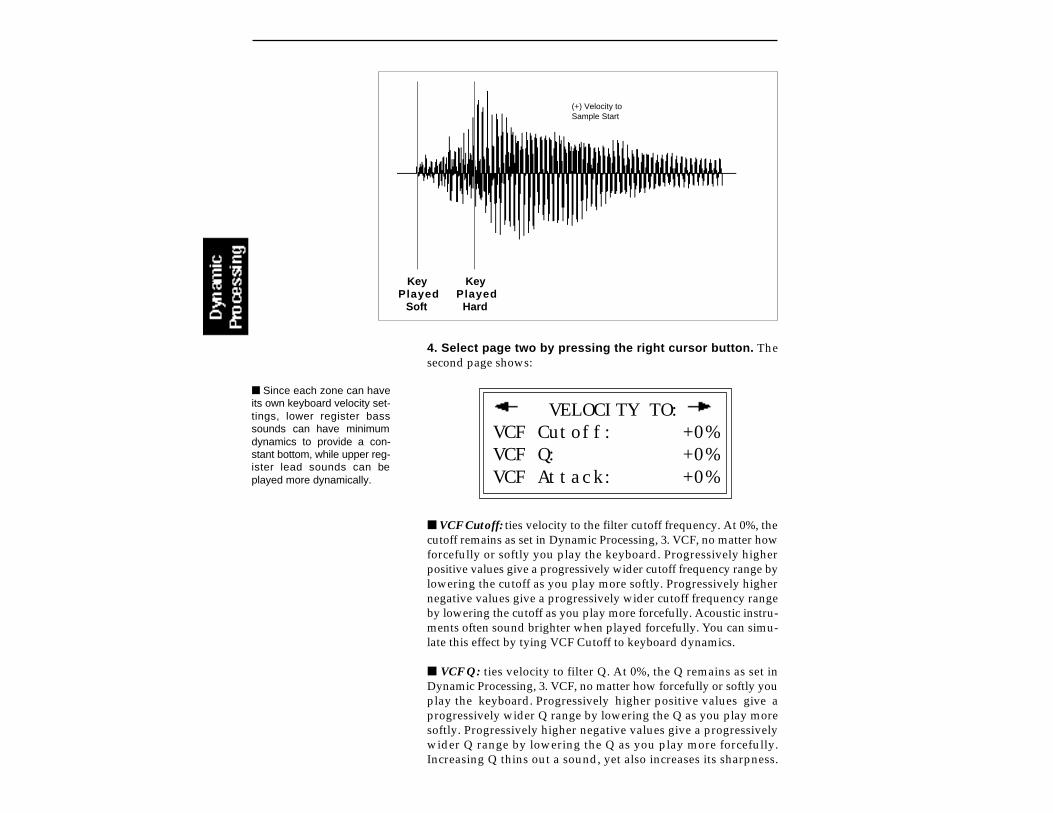
Key Played
Soft
Key Played
Hard
(+) Velocity toSample Start
4. Select page two by pressing the right cursor button. Thesecond page shows:
VELOCITY TO:VCF Cutoff: +0%VCF Q: +0%VCF Attack: +0%
VCF Cutoff: ties velocity to the filter cutoff frequency. At 0%, thecutoff remains as set in Dynamic Processing, 3. VCF, no matter howforcefully or softly you play the keyboard. Progressively higherpositive values give a progressively wider cutoff frequency range bylowering the cutoff as you play more softly. Progressively highernegative values give a progressively wider cutoff frequency rangeby lowering the cutoff as you play more forcefully. Acoustic instru-ments often sound brighter when played forcefully. You can simu-late this effect by tying VCF Cutoff to keyboard dynamics.
VCF Q: ties velocity to filter Q. At 0%, the Q remains as set inDynamic Processing, 3. VCF, no matter how forcefully or softly youplay the keyboard. Progressively higher positive values give aprogressively wider Q range by lowering the Q as you play moresoftly. Progressively higher negative values give a progressivelywider Q range by lowering the Q as you play more forcefully.Increasing Q thins out a sound, yet also increases its sharpness.
Since each zone can haveits own keyboard velocity set-tings, lower register basssounds can have minimumdynamics to provide a con-stant bottom, while upper reg-ister lead sounds can beplayed more dynamically.
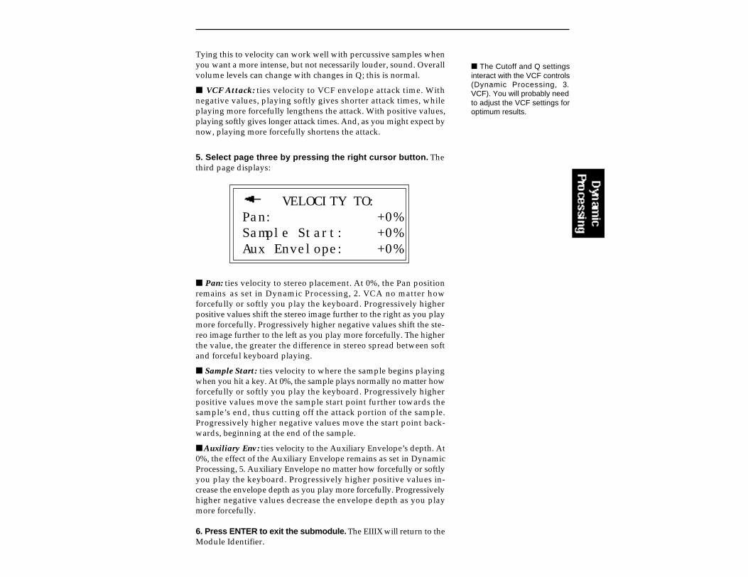
Tying this to velocity can work well with percussive samples whenyou want a more intense, but not necessarily louder, sound. Overallvolume levels can change with changes in Q; this is normal.
VCF Attack: ties velocity to VCF envelope attack time. Withnegative values, playing softly gives shorter attack times, whileplaying more forcefully lengthens the attack. With positive values,playing softly gives longer attack times. And, as you might expect bynow, playing more forcefully shortens the attack.
5. Select page three by pressing the right cursor button. Thethird page displays:
VELOCITY TO:Pan: +0%Sample Start: +0%Aux Envelope: +0%
Pan: ties velocity to stereo placement. At 0%, the Pan positionremains as set in Dynamic Processing, 2. VCA no matter howforcefully or softly you play the keyboard. Progressively higherpositive values shift the stereo image further to the right as you playmore forcefully. Progressively higher negative values shift the ste-reo image further to the left as you play more forcefully. The higherthe value, the greater the difference in stereo spread between softand forceful keyboard playing.
Sample Start: ties velocity to where the sample begins playingwhen you hit a key. At 0%, the sample plays normally no matter howforcefully or softly you play the keyboard. Progressively higherpositive values move the sample start point further towards thesample’s end, thus cutting off the attack portion of the sample.Progressively higher negative values move the start point back-wards, beginning at the end of the sample.
Auxiliary Env: ties velocity to the Auxiliary Envelope’s depth. At0%, the effect of the Auxiliary Envelope remains as set in DynamicProcessing, 5. Auxiliary Envelope no matter how forcefully or softlyyou play the keyboard. Progressively higher positive values in-crease the envelope depth as you play more forcefully. Progressivelyhigher negative values decrease the envelope depth as you playmore forcefully.
6. Press ENTER to exit the submodule. The EIIIX will return to theModule Identifier.
The Cutoff and Q settingsinteract with the VCF controls(Dynamic Processing, 3.VCF). You will probably needto adjust the VCF settings foroptimum results.
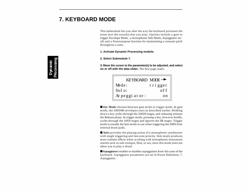
7. KEYBOARD MODE
This submodule lets you alter the way the keyboard processes thenotes (not the sounds) that you play. Options include a gate ortrigger Envelope Mode , a monophonic Solo Mode, Arpeggiator on/off, and a Nontranspose function for maintaining a constant pitchthroughout a zone.
1. Activate Dynamic Processing module.
2. Select Submodule 7.
3. Move the cursor to the parameter(s) to be adjusted, and selecton or off with the data slider. The first page reads:
KEYBOARD MODEMode: triggerSolo: offArpeggiator: on
Env Mode: chooses between gate mode or trigger mode. In gatemode, the AHDSR envelopes react as described earlier. Holdingdown a key cycles through the AHDS stages, and releasing initiatesthe Release phase. In trigger mode, pressing a key, however briefly,cycles through the AHD stages and ignores the SR stages. Triggermode is usually the best mode to use when triggering the EIIIX fromexternal drum pads.
Solo: provides the playing action of a monophonic synthesizerwith single triggering and last-note priority. Solo mode producesmore realistic effects when working with monophonic instrumentsounds such as solo trumpet, flute, or sax, since this mode does notallow you to play a chord.
Arpeggiator: enables or disables arpeggiation from this zone of thekeyboard. Arpeggiator parameters are set in Preset Definition, 7.Arpeggiator.

4. Select page two by pressing the right cursor button.The second page shows:
KEYBOARD MODE
Nontranspose: off
Nontranspose: lets a sample play throughout its assigned zone atits original pitch only—there will be no transposition. This is usefulwhen determining the original note at which a sample was recorded.Nontranspose is also useful if you’re playing drum parts from thekeyboard. Assigning a drum sound to a range consisting of severalkeys provides an easier target than being forced to hit a single key.
5. Press ENTER to exit the submodule. The EIIIX will return to theModule Identifier.
If you have a sound effectlayered behind a melodic line,but don’t want the effect totranspose as you play themelody, Nontranspose thesound effect.
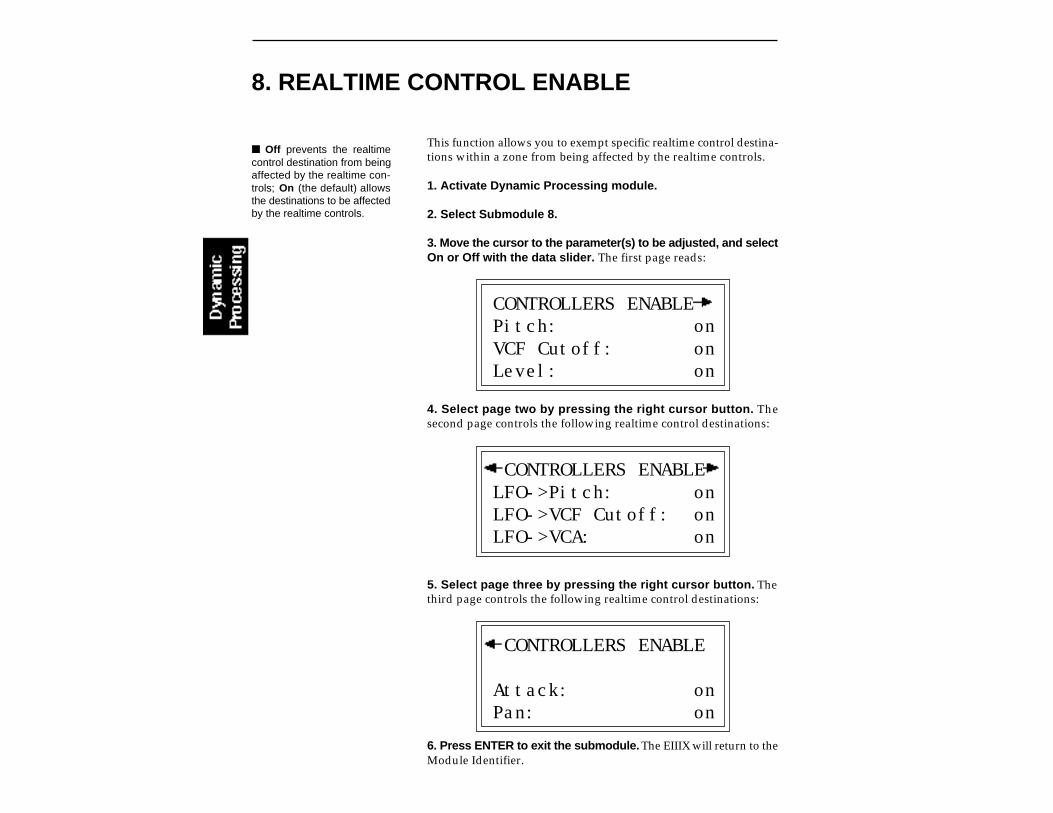
8. REALTIME CONTROL ENABLE
This function allows you to exempt specific realtime control destina-tions within a zone from being affected by the realtime controls.
1. Activate Dynamic Processing module.
2. Select Submodule 8.
3. Move the cursor to the parameter(s) to be adjusted, and selectOn or Off with the data slider. The first page reads:
CONTROLLERS ENABLEPitch: onVCF Cutoff: onLevel: on
4. Select page two by pressing the right cursor button. Thesecond page controls the following realtime control destinations:
CONTROLLERS ENABLELFO->Pitch: onLFO->VCF Cutoff: onLFO->VCA: on
5. Select page three by pressing the right cursor button. Thethird page controls the following realtime control destinations:
CONTROLLERS ENABLE
Attack: onPan: on
6. Press ENTER to exit the submodule. The EIIIX will return to theModule Identifier.
Off prevents the realtimecontrol destination from beingaffected by the realtime con-trols; On (the default) allowsthe destinations to be affectedby the realtime controls.

This function allows you to restrict the number of output channelsassigned to a particular zone and to route the zone to any pair ofoutput jacks.
The Emulator IIIX has 32 channels, which means that a maximum of32 different samples can be playing at once. A zone with onlyprimary samples assigned would use one channel per note played.A zone with primary and secondary samples assigned would usetwo channels per note.
This function is useful when you wish to process certain soundsseparately from the others or when you want to protect certaininstruments such as drums or bass from getting “stolen” by otherparts in your sequence.
The output channel assignments are disabled when the DynamicAllocation function (Master/Globals, 4) is turned On.
1. Activate Dynamic Processing module.
2. Select Submodule 9.
3. Select the lowest channel that you want the zone to use.
OUTPUT CHANNELSLowest Channel: 01Highest Channel: 32Submix: main
4. Move the cursor to line four and select the highest channelthat you want the zone to use.
(For example, selecting channels 01 (lowest) through 04 (highest)limits the zone to four channels. 01 through 32 allows the zone to useall channels.
5. Press ENTER to exit the submodule. The EIIIX will return to theModule Identifier.
9. OUTPUT CHANNELS
If a plug is not inserted into asubmix jack, any zone as-signed to that jack will be re-routed to the main outputs.
To “protect” a certain zonefrom channel ripoff: Assignoutput channels such that theprotected zone's channels arenot used in any other keyboardzone.
When all 32 channels aresounding and another key isplayed, the EIIIX will “steal” achannel from the oldestsounding note. This is knownas channel “ripoff”.


10-USING SCSI
SCSI BASICS 10-3
TERMINATION 10-5
MULTIPLE HOSTS 10-8
CONNECTION 10-10EXAMPLES


SCSI (pronounced skuzzy) stands for Small Computer SystemInterface. SCSI is an industry standard hardware and softwarespecification that allows high-speed data transfers between differ-ent pieces of equipment. SCSI devices can include hard disks, tapedrives, optical disks and other types of digital equipment.
Why Use SCSI?
SCSI is fast! SCSI is a parallel interface which transmits eight bitsof information at a time at high speed over the SCSI cable. MIDI, incomparison, is a serial interface which can only send one bit ofinformation at a time over its line.
Compatibility: Since SCSI is an industry standard, equipmentfrom many different manufacturers can be linked to work together.
Expandability: Up to eight SCSI devices can be linked together,including the Emulator III and its internal hard disk.
The SCSI BusYou may have noticed that the rear panel of most external storagedevices have two SCSI connectors. This is because SCSI devices areconnected together in a chain arrangement. The wires that connectthe different pieces of equipment are called the SCSI bus.
SCSI BASICS
Each device on the SCSI bus must have its own unique ID number (0-7).

ID NumbersEach device on the SCSI bus has its own ID number so that it candistinguish its data from data meant for another device. If the EIIIXwants to save data to a device with ID-2 for instance, all the otherdevices on the SCSI bus will ignore that data. If two devices have thesame ID number, chaos will surely reign. Each device must have itsown unique ID number.
The SCSI ID number of the Macintosh is fixed at ID-7 and cannot bechanged. The SCSI ID numbers of most other devices can bechanged.
Many SCSI devices have hardware defined ID numbers, whichmeans that there is a little switch on the device to change the IDnumber. The ID number of devices such as the RM45 removablemedia HD can only be changed by its internal jumper. This shouldbe left to an E-mu authorized dealer or service center. Most newerSCSI devices have a switch on the front or the back of the unit whichallows the ID number to be easily identified and changed.
The following is a list of the default SCSI ID numbers:
ID - 7 (fixed) MacintoshID - 6 Original EIII (this number can be changed)ID - 5 EIIIX (this number can be changed)ID - 4 UnassignedID - 3 UnassignedID - 2 EIIIX internal hard disk (if installed)ID - 1 Original EIII internal hard diskID - 0 Internal Macintosh HD (if installed)
Types of SCSI CablesThere are two basic types of SCSI cables in use: DB25 and 50-pinCentronics. The two types of cable can be identified by their connec-tors, which are quite different. When buying SCSI extension cables,it is important to choose ones with the right type of connectors, sincethe two types will not interconnect without a special adapter. Thetype of SCSI connectors on the original EIII are DB25 connectors.These are the type found most often on the back of personalcomputers. The SCSI connectors on the EIIIX are the 50-pinCentronics type. Use only high quality shielded cables that have allthe pins connected. Many cables only have some of the pins wired.
Length of SCSI CablesThe total length of the SCSI chain should not exceed 15 feet. Ageneral rule for SCSI cables is: The Shorter the Better!
Make sure you do not havetwo devices with the same IDnumber since this can causedamage to the startup directo-ries of the Macintosh or theEIIIX.
Always use 50-pinCentronics-type cables withthe EIIIX. These cables havemuch better electrical charac-teristics and have fewer prob-lems. Additionally, make surethat all 50 pins of the cablesare actually wired. SomeSCSI cables have only half ofthe pins wired.
The Emulator IIIX canchange it's ID number in orderto accommodate external de-vices having fixed ID num-bers.

In this example every device has a separate SCSI ID number. In this configuration the EIIIX should haveit's internal jumper changed to supply termination power. The last device in the chain is terminated with aSCSI Terminator Block.
TERMINATORS
Terminating resistors or terminators are special resistor packs thatare installed on the first and last device in the SCSI chain. Termina-tors are used to reduce line echos or standing waves on the SCSI bus.An analogy in an audio system would be impedance matching.
Terminators can either be hidden inside a SCSI device or they cantake the form of termination blocks which can simply be pluggedinto the SCSI port.
SCSI TERMINATOR BLOCK
Terminators apply power to an array of resistors to ensure a full 5volt swing between high and low levels on the SCSI line. The hostsystem (Macintosh or EIII) is required to provide terminationpower. Termination power has its own wire in the SCSI cable andsupplies power to the termination block. On external hard diskdrives, SCSI terminator power is almost always turned OFF and thedrives are left un-terminated.
Turn all devices OFF when-ever you change the SCSIcable. Devices left on whenthe cable is unplugged, maynot respond properly untilpowered off and on.

The EIIIX is shipped with termination power disconnected, butwith the termination resistors left in place. This is the properconfiguration for the EIIIX to be connected at the end on a SCSI chainwith a Macintosh at the other end. The EIIIX can supply terminationpower by connecting an internal jumper. The more devices youhave connected to SCSI and the longer your cables are, the more itbecomes important to have the cables properly powered and termi-nated.
Termination Power ExplainedThe diagram below shows a simplified ideal SCSI line. At each endwe have an identical termination with a 220Ω resistor to +5 volts anda 330Ω resistor connected to ground.
Some termination blockshave a LED to indicatewhether or not terminationpower is being supplied - avery useful feature.
“Master” devices such as the Macintosh and the EIIIX are config-ured internally as shown below. External SCSI devices (hard disks,optical disks, etc.) are usually shipped without any sort of termina-tion. The easiest way to add the termination resistors to an externalSCSI device is through the use of a termination block which plugsinto the second SCSI connector on the SCSI device.
Simply by plugging in the termination block we have added theresistors, but the termination block does not have +5 volts suppliedto it. Another wire in the SCSI cable has been reserved for “Termi-nator Power”.

The diagram below shows how terminator power is supplied.
An internal jumper in the EIIIX allows terminator power to besupplied from the EIIIX to the terminator block. Contact yourauthorized E-mu service center to have this service performed.
WARNINGConnecting the terminator power jumper on the EIIIX when theSCSI terminator power line already has power may cause seriousdamage to the EIIIX and to the other SCSI device!
The termination power jumper in the EIIIX should be connectedONLY if you are sure that no other device is supplying terminatorpower. The concept of terminator power is simple: Only one deviceon the SCSI chain should supply terminator power. Normallypower is always supplied by the computer. Therefore, if a computerwill be connected to the SCSI chain, don't connect terminator poweron the EIIIX!
Some terminator blocks have a LED which shows the presence of +5volts. We highly recommend this type of terminator block if youwill be changing your SCSI setup often.
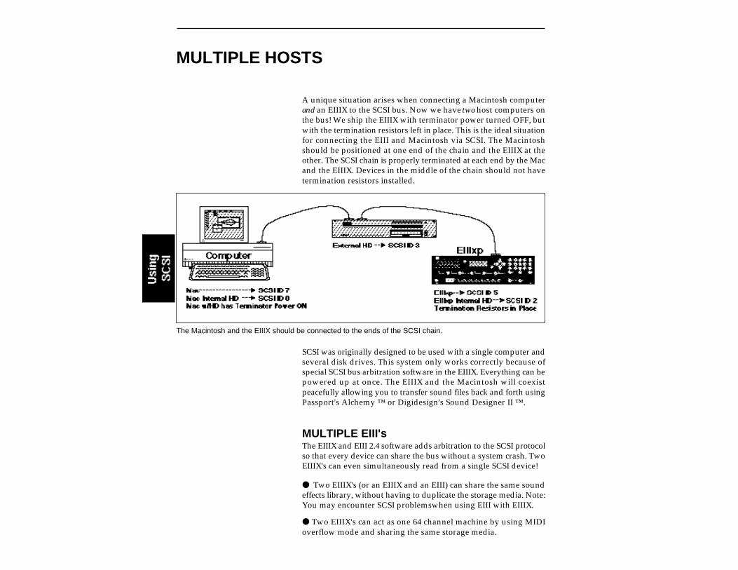
MULTIPLE HOSTS
A unique situation arises when connecting a Macintosh computerand an EIIIX to the SCSI bus. Now we have two host computers onthe bus! We ship the EIIIX with terminator power turned OFF, butwith the termination resistors left in place. This is the ideal situationfor connecting the EIII and Macintosh via SCSI. The Macintoshshould be positioned at one end of the chain and the EIIIX at theother. The SCSI chain is properly terminated at each end by the Macand the EIIIX. Devices in the middle of the chain should not havetermination resistors installed.
The Macintosh and the EIIIX should be connected to the ends of the SCSI chain.
SCSI was originally designed to be used with a single computer andseveral disk drives. This system only works correctly because ofspecial SCSI bus arbitration software in the EIIIX. Everything can bepowered up at once. The EIIIX and the Macintosh will coexistpeacefully allowing you to transfer sound files back and forth usingPassport's Alchemy ™ or Digidesign's Sound Designer II ™.
MULTIPLE EIII'sThe EIIIX and EIII 2.4 software adds arbitration to the SCSI protocolso that every device can share the bus without a system crash. TwoEIIIX's can even simultaneously read from a single SCSI device!
Two EIIIX's (or an EIIIX and an EIII) can share the same soundeffects library, without having to duplicate the storage media. Note:You may encounter SCSI problemswhen using EIII with EIIIX.
Two EIIIX's can act as one 64 channel machine by using MIDIoverflow mode and sharing the same storage media.
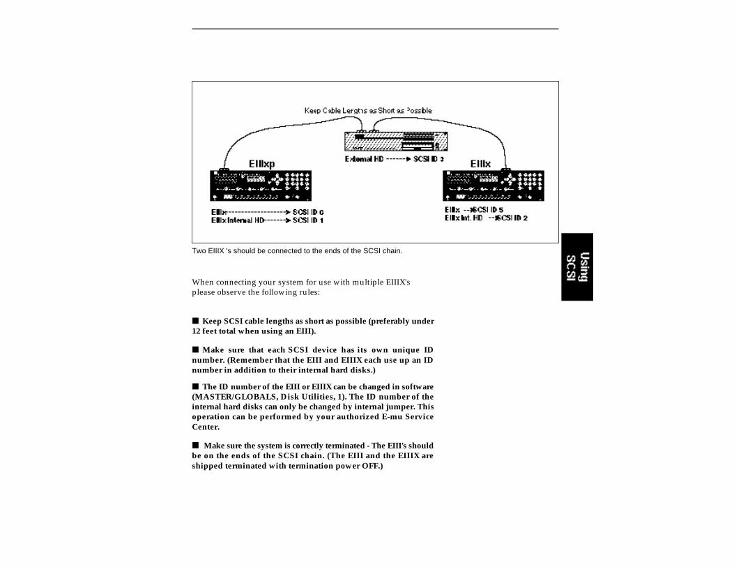
Two EIIIX 's should be connected to the ends of the SCSI chain.
When connecting your system for use with multiple EIIIX'splease observe the following rules:
Keep SCSI cable lengths as short as possible (preferably under12 feet total when using an EIII).
Make sure that each SCSI device has its own unique IDnumber. (Remember that the EIII and EIIIX each use up an IDnumber in addition to their internal hard disks.)
The ID number of the EIII or EIIIX can be changed in software(MASTER/GLOBALS, Disk Utilities, 1). The ID number of theinternal hard disks can only be changed by internal jumper. Thisoperation can be performed by your authorized E-mu ServiceCenter.
Make sure the system is correctly terminated - The EIII's shouldbe on the ends of the SCSI chain. (The EIII and the EIIIX areshipped terminated with termination power OFF.)

SIMPLE EIIIX SETUP
In this simple scenario, the EIIIX is the “Host Computer”and does not contain its own internal hard disk. Asmall system such as this may work fine without the terminator block being powered.
CONNECTION EXAMPLES
Multiple EIIIX/Macintosh Setup

SCSI PROBLEMS
In diagnosing SCSI problems the first rule is: Don't panic, experi-ment! If you have several SCSI devices hooked up, try disconnect-ing one of the devices and maybe change the order of the units onthe line. There are quite a number of different SCSI drives on themarket each with slightly different electrical characteristics. Thefollowing checklist may help you find the solution to your uniqueSCSI setup.
1. Read the documentation again. Learn all you can about yourperipheral devices. The answer to your problem may be right infront of you.
2. Check the SCSI ID numbers. No two numbers on the bus can bethe same.
3. Play with the order in which devices are powered up. Normallythe “Big Bang” method works best (turn everything on at once), butanother order may work better in your unique system. Experiment!
4. Always suspect the cable when something doesn't work on theSCSI bus. Remember: The shorter the cables are, the better.
5. Simplify the situation. Disconnect one or more drives until youget the system to work. Try turning off Multifinder until you geteverything up and running.
6. Are the ends of the SCSI bus terminated? If the EIIIX is the only“Master” on the bus, is termination power supplied to the lastdevice? Try inserting a termination block in the center of a long SCSIchain.
7. Try lifting the grounds on the EIIIX or the external SCSIdevices. Use a three-to-two prong ground lift plug. Try changingoutlets.
8. Are you using software version 2.4 with an EIII? This is abso-lutely necessary as this was the first version to contain the busarbitration software. All versions of EIIIX software contain busarbitration software.
9. If all else fails, call us. We're here if you need us. 408-438-1921Telephone support hours are 9:00 to 5:00 PST, Monday throughFriday.

SCSI NOISE ON THE AUDIO LINEIn some cases, EIIIX connected to the SCSI bus and to a mixerproduces noise (beeps) from the mixer output. This noise typicallyis on a threshold-of-hearing level when the proper audio level is set.In some setups noise get worse, especially when Macintosh ispresent on SCSI bus. In some cases no noise is detected. Whenmeasuring the output (or listening to) EIIIX own outputs, no noiseis detected.
The following measures, depending on a setup, will either com-pletely eliminate the noise or bring it down to an unaudible level:
USE BALANCED OUTPUTSThis completely solves the noise problem (even with Macintosh onthe SCSI bus).
USE STEREO 1/4" CABLES WITH UNBALANCED INPUTS OFYOUR MIXERThis will eliminate ground as as a signal conductor since the EIIIX1/4" jacks are indeed BALANCED outputs. This brings the noise tothe extremely low level which is barely audible only when all thesliders of a mixer are all the way up (don't play samples in thissettings - you may blow your speakers).


11-APPENDIX
KEYBOARD 11-2CHARACTER CHART
EIIIX MENU MAP 11-3
MIDI KEY CHART 11-4
MIDI CHART 11-5
SPECIFICATIONS 11-6
ERROR CODES 11-7
TROUBLESHOOTING 11-9
WARRANTY 11-15
INDEX 11-16
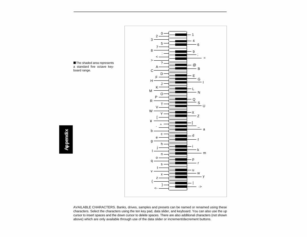
AVAILABLE CHARACTERS. Banks, drives, samples and presets can be named or renamed using thesecharacters. Select the characters using the ten key pad, data slider, and keyboard. You can also use the upcursor to insert spaces and the down cursor to delete spaces. There are also additional characters (not shownabove) which are only available through use of the data slider or increment/decrement buttons.
@
CE
HJ
LO
QT
V
X[
]`
b
?
D
I
N
S
Y
^
A B
F G
KM
PR
UW
Z¥
_a
c defg
hij
kl mno pq
rst
uv wx yz | -><-
>< =
;: 987
6543
2 10
The shaded area representsa standard five octave key-board range.
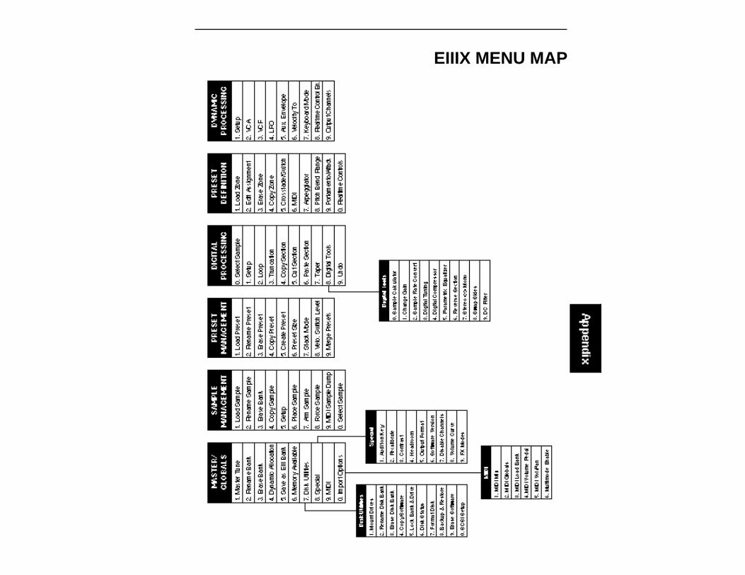
EIIIX MENU MAP
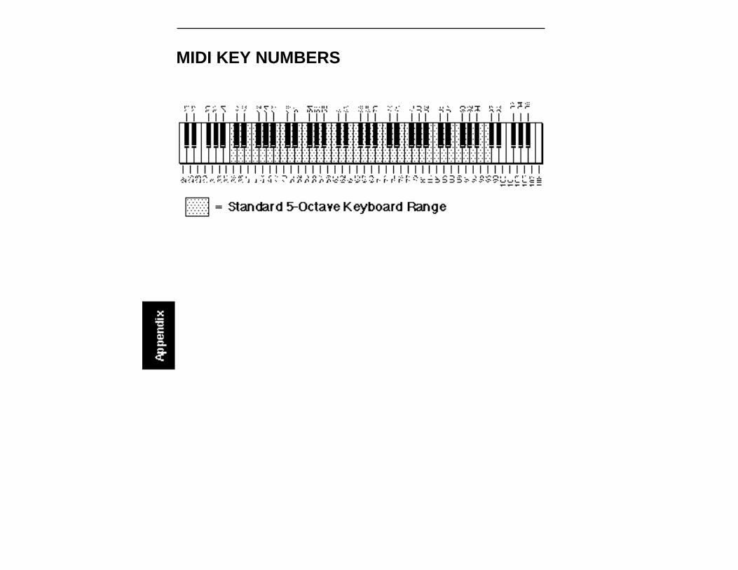
MIDI KEY NUMBERS
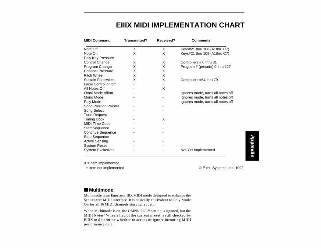
EIIIX MIDI IMPLEMENTATION CHART
MIDI Command Transmitted? Received? Comments_____________________________________________________________________
Note Off X X Keys#21 thru 108 (A1thru C7)Note On X X Keys#21 thru 108 (A1thru C7)Poly Key Pressure - -Control Change X X Controllers # 0 thru 31Program Change X X Program # (preset#) 0 thru 127Channel Pressure X XPitch Wheel X XSustain Footswitch X X Controllers #64 thru 79Local Control on/off - -All Notes Off - XOmni Mode off/on - - Ignores mode, turns all notes offMono Mode - - Ignores mode, turns all notes offPoly Mode - - Ignores mode, turns all notes offSong Position Pointer - -Song Select - -Tune Request - -Timing clock - XMIDI Time Code - -Start Sequence - -Continue Sequence - -Stop Sequence - -Active Sensing - -System Reset - -System Exclusives - - Not Yet Implemented_____________________________________________________________________
X = item implemented- = item not implemented © E-mu Systems, Inc. 1992
MultimodeMultimode is an Emulator IIIX MIDI mode designed to enhance theSequencer/MIDI interface. It is basically equivalent to Poly ModeOn for all 16 MIDI channels simultaneously.
When Multimode is on, the OMNI/POLY setting is ignored, but theMIDI Notes/Wheels flag of the current preset is still checked byEIIIX to determine whether to accept or ignore incoming MIDIperformance data.
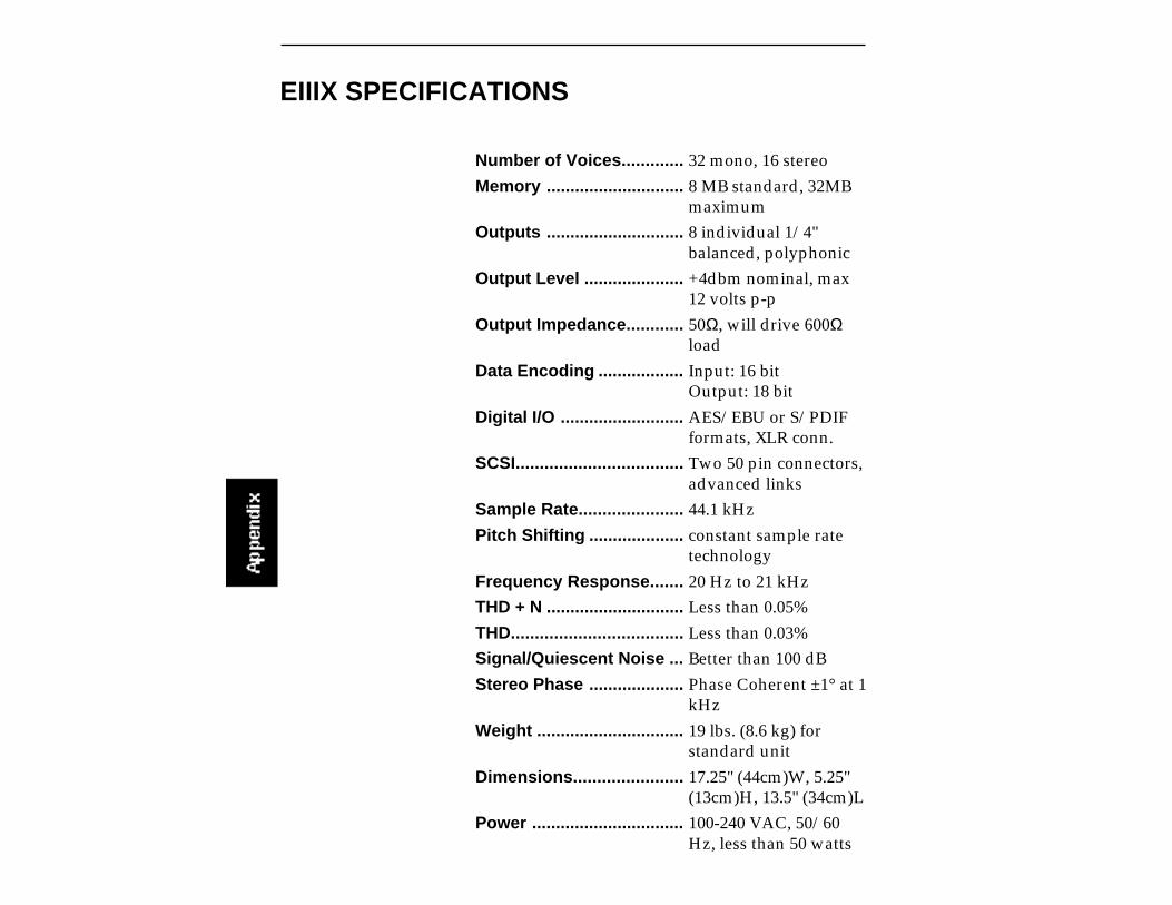
EIIIX SPECIFICATIONS
Number of Voices............. 32 mono, 16 stereo
Memory ............................. 8 MB standard, 32MBmaximum
Outputs ............................. 8 individual 1/4"balanced, polyphonic
Output Level ..................... +4dbm nominal, max12 volts p-p
Output Impedance............ 50Ω, will drive 600Ωload
Data Encoding .................. Input: 16 bitOutput: 18 bit
Digital I/O .......................... AES/EBU or S/PDIFformats, XLR conn.
SCSI................................... Two 50 pin connectors,advanced links
Sample Rate...................... 44.1 kHz
Pitch Shifting .................... constant sample ratetechnology
Frequency Response....... 20 Hz to 21 kHz
THD + N ............................. Less than 0.05%
THD.................................... Less than 0.03%
Signal/Quiescent Noise ... Better than 100 dB
Stereo Phase .................... Phase Coherent ±1° at 1kHz
Weight ............................... 19 lbs. (8.6 kg) forstandard unit
Dimensions....................... 17.25" (44cm)W, 5.25"(13cm)H, 13.5" (34cm)L
Power ................................ 100-240 VAC, 50/60Hz, less than 50 watts
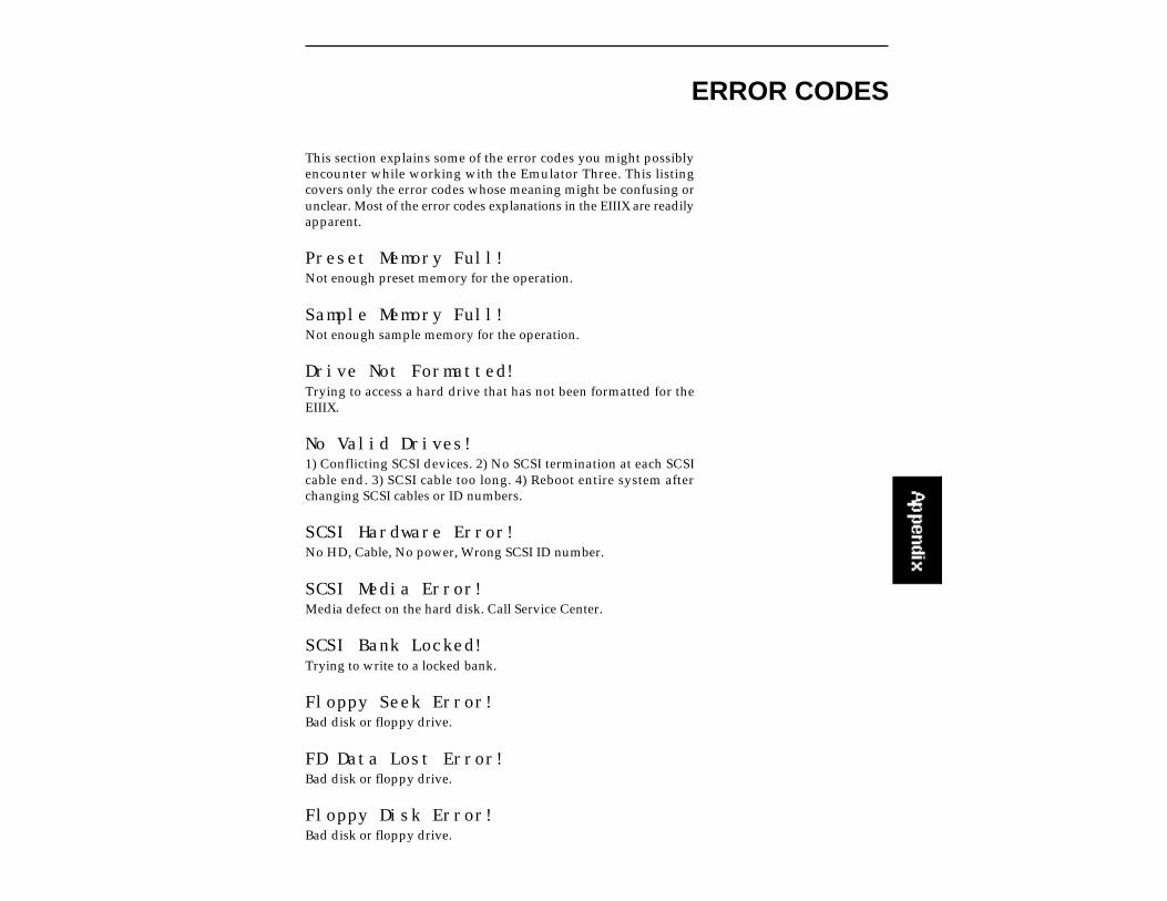
ERROR CODES
This section explains some of the error codes you might possiblyencounter while working with the Emulator Three. This listingcovers only the error codes whose meaning might be confusing orunclear. Most of the error codes explanations in the EIIIX are readilyapparent.
Preset Memory Full!Not enough preset memory for the operation.
Sample Memory Full!Not enough sample memory for the operation.
Drive Not Formatted!Trying to access a hard drive that has not been formatted for theEIIIX.
No Valid Drives!1) Conflicting SCSI devices. 2) No SCSI termination at each SCSIcable end. 3) SCSI cable too long. 4) Reboot entire system afterchanging SCSI cables or ID numbers.
SCSI Hardware Error!No HD, Cable, No power, Wrong SCSI ID number.
SCSI Media Error!Media defect on the hard disk. Call Service Center.
SCSI Bank Locked!Trying to write to a locked bank.
Floppy Seek Error!Bad disk or floppy drive.
FD Data Lost Error!Bad disk or floppy drive.
Floppy Disk Error!Bad disk or floppy drive.
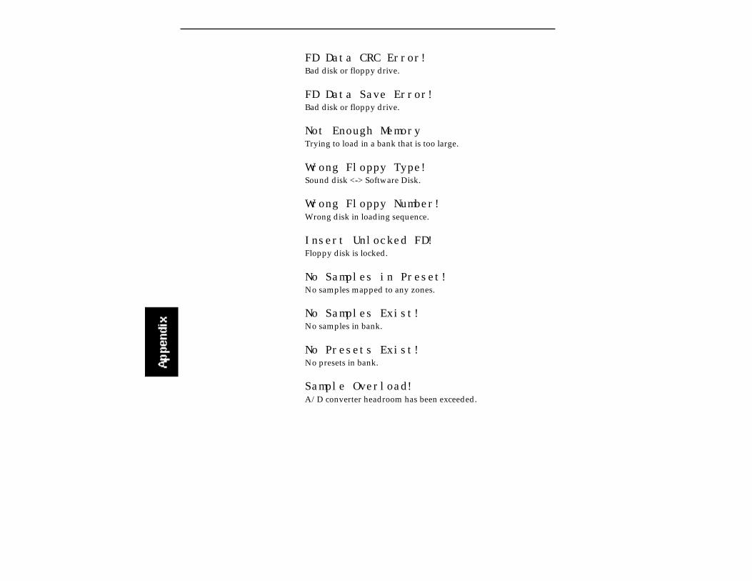
FD Data CRC Error!Bad disk or floppy drive.
FD Data Save Error!Bad disk or floppy drive.
Not Enough MemoryTrying to load in a bank that is too large.
Wrong Floppy Type!Sound disk <-> Software Disk.
Wrong Floppy Number!Wrong disk in loading sequence.
Insert Unlocked FD!Floppy disk is locked.
No Samples in Preset!No samples mapped to any zones.
No Samples Exist!No samples in bank.
No Presets Exist!No presets in bank.
Sample Overload!A/D converter headroom has been exceeded.
TROUBLESHOOTING
This section explains some of the problems you might possiblyencounter while working with the Emulator IIIX. Before assumingthat your EIIIX is faulty, check the following list which details thecorrective action you can take yourself without having to call aservice center. If you have any doubts or questions, get in touch withyour nearest E-mu dealer or call the E-mu customer service depart-ment at (408) 438-1921, between the hours of 8:30 am and 5:30 pmMonday through Friday.
The Emulator IIIX will not boot.If the Emulator IIIX fails to boot, first disconnect any external SCSIdevices and try again. External SCSI devices should be switched onbefore the Emulator IIIX.
Problem:The unit is completely dead. No lights, no sound.Cause:The fuse may be blown.Solution:The two fuses are located on the AC power receptacle. Squeeze thetwo tabs together to open the fuse drawer and check the fuses. TheEIIIX uses two 250V, 2A, fast-blo mini-fuses. If a fuse that has beenreplaced blows again, do not attempt another replacement. Consultyour dealer or authorized E-mu service center.
Problem:The unit is completely dead. No lights no sound. Fuse is OK.Cause:The power supply may be damaged.Solution:Consult your dealer or authorized E-mu service center.
Problem:The unit lights up and the hard disk starts, but does not boot.Cause:The operating system on the hard disk may have been damaged.Solution:Try booting the EIIIX from floppy disk based software. If the unit stillwon’t boot, consult your dealer or authorized E-mu service center.If the unit boots from the floppy software, try copying the softwareto the internal hard disk (Master/Globals module, 7. Disk Utilities,4. Copy Software). As a last resort, reformat the hard disk.
Audio Problems
Problem:The EIIIX powers up normally, but does not make any sound.Cause:Proper audio connections may not have been made.Solution:Try listening directly to the stereo output using headphones to verifythat the EIIIX is at fault. Check that proper audio connections havebeen made.
Problem:The EIIIX powers up normally, but does not make any sound.Cause:The front panel controls (volume slider) may need recalibration.Solution:Recalibrate the front panel controls using the Recalibrate functionlocated under Special in the Master/Globals module.
Problem:The EIIIX powers up normally, but does not make any sound.Cause:All output channels are disabled.Solution:Enable all channels using the Disable Channels function (Master/Globals module, 8. Special, 7. Disable Channels).
Problem:The EIIIX powers up normally, but does not make any sound.Cause:Proper MIDI connections may not have been made.Solution:Try pressing the Audition key on the front panel. Check that properMIDI connections have been made.
Problem:The digital audio ouput level is too low when a single channel isplayed.Cause:Because of the nature of sampling instruments, each additionalchannel played adds +3dB to the headroom requirement. A singlechannel on the EIIIX comes out about -6 dB down.Solution:Make sure the Master Volume control is at maximum. Set theheadroom adjustment (Master/Globals, Special, 4) to 0 dB. Allvolume adjustments in the EIIIX affect the digital output level.
Audio Problems (cont)
Problem:Certain sounds do not play polyphonically.Cause:The zone may be in solo mode, or only assigned to one outputchannel.Solution:Disable solo mode and check output channel assignment.
Problem:Certain sounds cut off prematurely.Cause:More than 32 mono, or 16 stereo channels are playing. Or, if specificoutput channels are assigned, two sounds may be “ripping eachother off”.Solution:Check output channel assignment (Dynamic Processing, 9). Tryturning Dynamic Allocation (Master/Globals, 4) on. Set releasetimes on VCA to a shorter setting.
Problem:Stereo samples are only heard out of one side.Cause:Disable side function is turned on.Solution:Turn disable side function (Dynamic Processing,1) off in the zone.
Problem:Audible hum in system when EIIIX is connected.Cause:There is a ground loop present in the audio system.Solution:Find and eliminate the ground loop.
Functional Problems
Problem:Front panel buttons double trigger.Cause:Buttons need cleaning.Solution:Consult your dealer or authorized E-mu service center.

Functional Problems (cont)
Problem:Looping only works while in the Digital Processing module.Cause:Disable Loop function is turned on.Solution:Turn disable loop function (Dynamic Processing,1. Setup) off in thezone.
Problem:Controllers (wheels, pedal, pressure) do not work at all.Cause:Controllers are not assigned in the preset.Solution:Assign the controllers to the desired destinations (Preset Definition,0. Realtime Controls).
Problem:Controllers (wheels, pedal, pressure) do not work at all and areassigned correctly.Cause:Controllers are disabled in Realtime Control Enable section.Solution:Enable realtime controllers for the selected zone (Dynamic Process-ing, 8. Realtime Control Enable).
Problem:The footpedal or LFO has little or no effect when assigned to VCA.Cause:The initial VCA level is set at 100%.Solution:Lower the initial VCA setting as desired.
MIDI ProblemsSince MIDI setups can be quite complex, make sure that you have allthe MIDI parameters (on the EIIIX and external MIDI devices) setcorrectly before you become daunted. Remember that the MIDIGlobal commands override individual preset MIDI settings. On theEmulator IIIX, MIDI parameters are located in the Preset Definitionmodule,(6. MIDI Setup) and in the Master/Globals module, (9.MIDI, 2. MIDI Globals).
MIDI Problems (cont)
Problem:The EIIIX does not respond to the MIDI parameters as programmed.Cause:MIDI Globals are turned ON.Solution:Turn OFF MIDI Globals (Master/Globals, 9. MIDI, 2. MIDI Globals).
Problem:The EIIIX does not respond to the modulation wheels or pressurefrom an external MIDI controller.Cause:MIDI controllers are not assigned in the MIDI submodule or Real-time Control module.Solution:Assign proper controller channel numbers to Left Wheel, RightWheel, Pedal, Pressure, MIDI A and B, then assign MIDI A and B todesired destinations (See Preset Definition, 6. MIDI Setup). CheckRealtime Control routings (Preset Definition, 0. Realtime Controls).
Hard Disk Problems
Problem:The EIIIX display reads “Disk Not Formatted”.Cause:The internal hard disk or an external SCSI device may have crashed.Solution:First, disconnect any external SCSI devices and reboot. If this fails,try reformatting the internal hard disk. If reformatting fails, consultyour dealer or authorized E-mu service center.
Problem:The EIIIX display reads “Disk Not Formatted” and an external SCSIdevice is connected.Cause:The hard disk may have crashed, the SCSI cable may be too long ortwo devices may have the same SCSI ID number.Solution:Try using a shorter SCSI cable (maximum cable length is about 12feet) and check that no two devices have the same ID number.
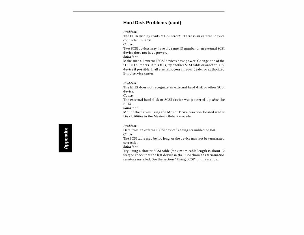
Hard Disk Problems (cont)
Problem:The EIIIX display reads “SCSI Error!”. There is an external deviceconnected to SCSI.Cause:Two SCSI devices may have the same ID number or an external SCSIdevice does not have power.Solution:Make sure all external SCSI devices have power. Change one of theSCSI ID numbers. If this fails, try another SCSI cable or another SCSIdevice if possible. If all else fails, consult your dealer or authorizedE-mu service center.
Problem:The EIIIX does not recognize an external hard disk or other SCSIdevice.Cause:The external hard disk or SCSI device was powered-up after theEIIIX.Solution:Mount the drives using the Mount Drive function located underDisk Utilities in the Master/Globals module.
Problem:Data from an external SCSI device is being scrambled or lost.Cause:The SCSI cable may be too long, or the device may not be terminatedcorrectly.Solution:Try using a shorter SCSI cable (maximum cable length is about 12feet) or check that the last device in the SCSI chain has terminationresistors installed. See the section “Using SCSI” in this manual.

Please read this warranty, as it gives you specific legal rights.
Length of WarrantyYour Emulator Three XP warranty covers all defects in materials and workmanship for a period of oneyear (90 days for disk drives) from the date of purchase by the original owner, provided that theWarranty Registration Card is filled out and returned to E-mu Systems within 14 days from the dateof purchase. Cases may arise where E-mu's Service Department or one of E-mu's authorized servicecenters will ask for a copy of your sales receipt to facilitate warranty service. Please keep your purchasereceipt in a safe place.
E-mu Systems does not cover: Damages due to improper or inadequate maintenance, accident, abuse, misuse, alteration, unautho-rized repairs, tampering, or failure to follow normal operating procedures as outlined in the owner'smanual. Deterioration or damage of the cabinet. Damages occurring during any shipment of theEmulator Three XP for any reason. An Emulator Three XP that has in any way been modified byanyone other than E-mu Systems, Inc.
Limitation of Implied WarrantiesNo warranty is expressed or implied. E-mu Systems specifically disclaims the implied warranties ofmerchantibility and fitness for a particular purpose.
Exclusion of Certain DamagesE-mu Systems' liability for an Emulator Three XP found defective is limited to repair or replacementof the unit at E-mu's option. In no event shall E-mu Systems be liable for damages based oninconvenience, whether incidental or consequential, loss of use of the unit, loss of time, interuptedoperation or commercial loss, or any other consequential damages.Some states do not allow limitation of the duration of implied warranties or the exclusion or limitation ofincidental or consequential damages, so the above limitations and exclusions may not apply to you.
How To Obtain Warranty ServiceAll E-mu products are manufactured with the highest standards of quality. If you find that yourinstrument does require service, it may be done by any authorized E-mu service center. If you areunable to locate a service center in your area, please contact E-mu Systems Service Department at (408)438-1921. They will either refer you to an authorized service center or ask that you return yourEmulator Three XP to the factory. When returning an EIIIX to the factory, you will be issued a ReturnMerchandise Authorization number (RMA). Please label all cartons , shipping documents andcorrespondance with this number. E-mu suggests you carefully and securely pack your EIIIX forreturn to the factory. Mark the outside of the shipping carton clearly with your RMA number. Send toE-mu Systems, Inc. 1600 Green Hills Road, Scotts Valley, California, 95066. You must pre-pay shippingcharges to E-mu Systems. E-mu will pay return shipping fees. You will be responsible for any damageor loss sustained during shipment in any direction.
8/92
E-MU SYSTEMS PRODUCT WARRANTY

INDEX
AAC power connection 1-12, 13aftertouch See pressureAKAI import 4-37alternate tunings 9-6analog sampling 1-10, 1-12, 3-20, 5-8arpeggiator 8-22
footswitch control of 8-31attack 9-8, 9-12, 9-16
velocity control of 9-19trajectory 8-27
audition key 2-3, 4-22auto correlate 7-10, 7-11auto normalize 5-9auto placement 5-9auto truncate 5-9auxiliary envelope 9-15, 3-14
velocity control of 9-19
Bbalanced outputs 1-11backup 4-17bank
definition 1-18loading 2-6saving 2-5save as EIII bank 4-6
booting 1-21
Ccalculator, sample 7-25channel disable 4-26change gain 7-25chorus 9-6compressor
digital 7-30loop 7-3, 7-11
connectionsaudio 1-10digital I/O 1-10, 1-12MIDI 1-10power 1-12SCSI 1-5, 10-10
contourSee envelope generator
contrast, LCD 4-23controls 2-2 -> 2-9control recalibration 4-22copy section 7-4, 7-14copy software 4-12crossfade/switch mode 8-14
footswitch control of 8-31cruz control 8-25current preset 1-20current sample 1-20cursor 1-22, 2-3, 2-4curves
gain change 7-14taper 7-12volume 4-28
cut section 7-4, 7-16cutoff, VCF 9-10
velocity control of 9-18
DDC filter 7-38data slider 1-22, 2-2decay 9-8, 9-12, 9-16default 1-21delay
LFO 9-13zone 9-6
digital processing 7-1 -> 7-39digital compressor 7-30digital tuning 7-29disable channels 4-26disk utilities 4-8disk drive backup 4-17disk status 4-14drive mounting 4-10drive select 2-7dynamic allocation 4-5dynamic processing 3-9, 9-1 -9-23
background 9-2

Kkey number chart 11-4keyboard mode 9-20keyboard tuning See master tunekeyboard tracking, filter 9-11
LLCD contrast control 4-23LFO 9-13, 3-13load bank 2-4load preset 6-2, 3-23load sample 5-3lock bank & drive 4-13looping 7-2
auto correlate 7-10, 7-11disable loop 9-7loop compression 7-11loop in release 7-8reverse looping 7-8setting the loop 7-10type 7-8
Mmain outputs 1-11, 9-23main output format 4-25mapping, keyboard
See edit assignmentmaster/globals menu 4-1 -> 4-32master tune 4-2master volume 2-2memory available 4-7MIDI A, B assignments 8-19, 8-20, 8-28MIDI basic channel 4-32, 8-18MIDI channel selection
in poly mode 4-32in multimode 2-8
MIDI footswitch 8-21MIDI globals 4-32MIDI in 1-10, 1-12MIDI key number chart 11-4MIDI load bank 4-33MIDI mix 4-31MIDI mode 4-32, 8-18MIDI out 1-10, 1-12MIDI overflow 4-32, 8-18MIDI panning control 4-31
EEIIIX menu map 11-3edit assignment 3-7, 8-6EMAX II import 4-45enter button 2-3envelope amount, filter 9-10envelope generator
description 9-9auxiliary envelope 9-15VCA 9-9VCF 9-12
envelope mode 9-20equalizer, parametric 7-34erase bank 4-4erase disk bank 4-11erase software 4-20escape button 2-3
Ffilter 3-9, 7-34, 9-10flip-flop keys 4-30floppy disk 1-18footswitches, MIDI 8-21, 3-18format disk 4-15fuse 1-13FX modes 4-30
Ggain change 7-25gain, sampling 5-8glissando, arpeggiator 8-24globals, MIDI 4-32guided tours 3-3 ->3-24
Hheadroom adjustment 4-24hold 9-8, 9-12, 9-16
Iimport options 4-37increment/decrement buttons 1-22, 2-2inputs
analog 1-10, 1-12digital input 1-10MIDI input 1-10, 1-12
inverted envelope 9-12, 9-15
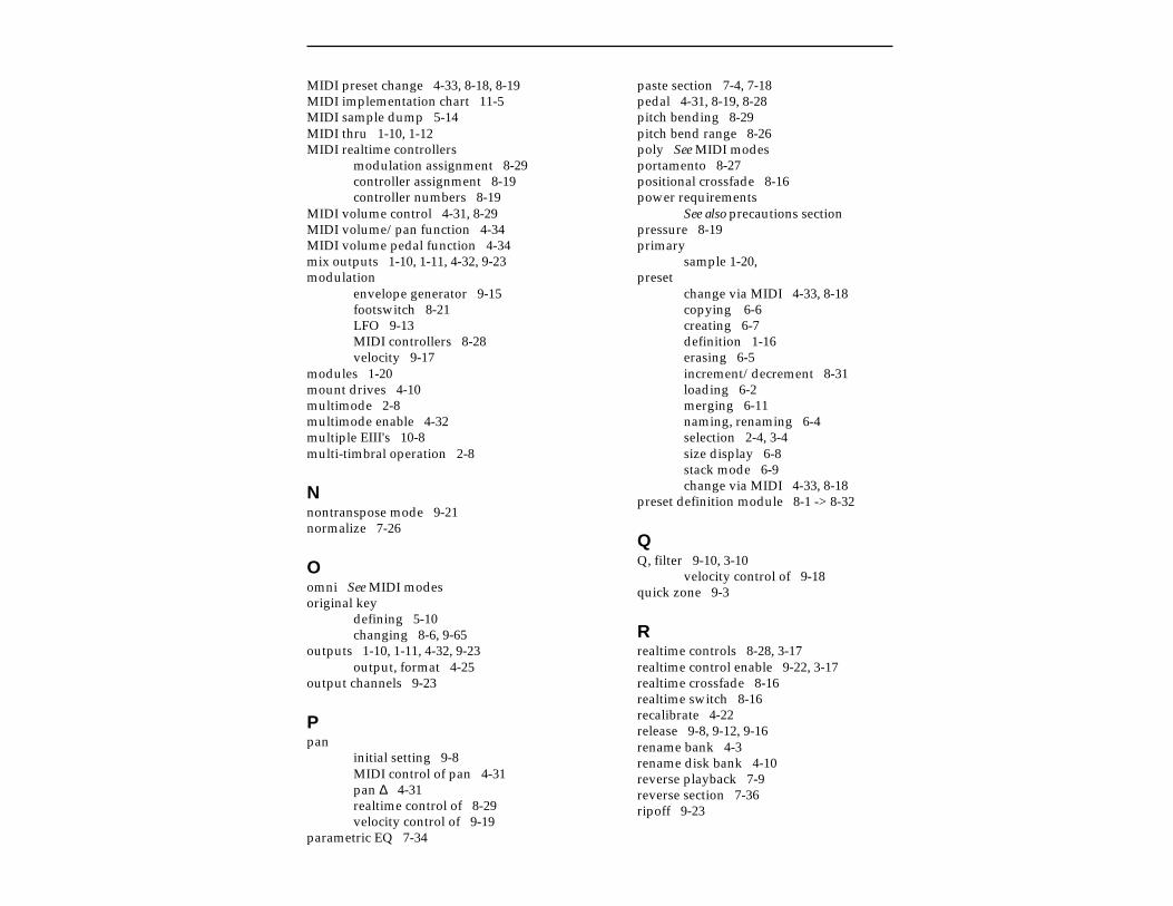
MIDI preset change 4-33, 8-18, 8-19MIDI implementation chart 11-5MIDI sample dump 5-14MIDI thru 1-10, 1-12MIDI realtime controllers
modulation assignment 8-29controller assignment 8-19controller numbers 8-19
MIDI volume control 4-31, 8-29MIDI volume/pan function 4-34MIDI volume pedal function 4-34mix outputs 1-10, 1-11, 4-32, 9-23modulation
envelope generator 9-15footswitch 8-21LFO 9-13MIDI controllers 8-28velocity 9-17
modules 1-20mount drives 4-10multimode 2-8multimode enable 4-32multiple EIII's 10-8multi-timbral operation 2-8
Nnontranspose mode 9-21normalize 7-26
Oomni See MIDI modesoriginal key
defining 5-10changing 8-6, 9-65
outputs 1-10, 1-11, 4-32, 9-23output, format 4-25
output channels 9-23
Ppan
initial setting 9-8MIDI control of pan 4-31pan ∆ 4-31realtime control of 8-29velocity control of 9-19
parametric EQ 7-34
paste section 7-4, 7-18pedal 4-31, 8-19, 8-28pitch bending 8-29pitch bend range 8-26poly See MIDI modesportamento 8-27positional crossfade 8-16power requirements
See also precautions sectionpressure 8-19primary
sample 1-20,preset
change via MIDI 4-33, 8-18copying 6-6creating 6-7definition 1-16erasing 6-5increment/decrement 8-31loading 6-2merging 6-11naming, renaming 6-4selection 2-4, 3-4size display 6-8stack mode 6-9change via MIDI 4-33, 8-18
preset definition module 8-1 -> 8-32
QQ, filter 9-10, 3-10
velocity control of 9-18quick zone 9-3
Rrealtime controls 8-28, 3-17realtime control enable 9-22, 3-17realtime crossfade 8-16realtime switch 8-16recalibrate 4-22release 9-8, 9-12, 9-16rename bank 4-3rename disk bank 4-10reverse playback 7-9reverse section 7-36ripoff 9-23

Ttaper 7-22ten-key pad 2-2tracking, VCF 9-10transpose 2-9, 3-6troubleshooting 11-8truncation 7-13
truncate after loop 7-12tuning
alternate tuning 9-6digital tuning of samples 7-29master tune 4-2to other instruments 3-5, 4-2zone tuning 9-6
Uundo 7-5, 7-39
VVCA 9-8, 3-12
level setting 9-8realtime control of 8-29
VCF 9-10, 3-9cutoff 9-10, 3-9Q control 9-10realtime control of 8-29
velocity 9-17, 3-15crossfade 8-16switch 8-16switch level 6-10
volumemain volume control 2-2MIDI volume control 4-31, 4-34volume curves 4-28, 4-29
Wwarranty 11-5waveforms, LFO 9-13wheels, modulation 8-19, 8-28, 3-17
Ssample management 5-1 -> 5-14, 3-20sample
arm sample 5-12calculator 7-25copying 5-7erasing 5-6force sample 5-13length 5-9loading 5-3place sample 5-10renaming 5-5reversing 7-5selecting 5-2, 7-4setup 5-8source 5-9threshold 5-8
sample rate convert 7-28sample start 9-19sampling 1-14, 3-20saving, banks 1-21, 2-5, 3-5saving as EIII bank 4-6scrub wheel 7-6SCSI
basic information 10-3connection examples 10-10initial setup 1-5problems 10-12SCSI setup 4-9termination 10-5
secondary 1-20software version 4-25solo mode 9-20specifications
MIDI 11-5technical 11-6
split keyboard 8-6, 9-2, 9-3stack mode 6-9stereo <-> mono 7-37submix outputs 1-11, 9-23submodule 1-20sustain
auxiliary envelope 9-16footswitch control of 8-31VCA 9-8VCF 9-12
swap sides 7-37

Zzone
chorus 9-6copying 8-11definition 1-17delay 9-6erase 8-9loading 8-2selecting 9-4, 3-8tuning 9-6

NOTES