important instructions to examiners - msbte study...
TRANSCRIPT

MAHARASHTRA STATE BOARD OF TECHNICAL EDUCATION
(Autonomous)
Summer – 2014 Examinations
Subject Code: 17322 Model Answer Page No: 1 of 18
Important Instructions to examiners:
1) The answers should be examined by key words and not as word-to-word as
given in the model answer scheme.
2) The model answer and the answer written by candidate may vary but the
examiner may try to assess the understanding level of the candidate.
3) The language errors such as grammatical, spelling errors should not be given
more Importance (Not applicable for subject English and Communication
Skills).
4) While assessing figures, examiner may give credit for principal components
indicated in the figure. The figures drawn by candidate and model answer may
vary. The examiner may give credit for any equivalent figure drawn.
5) Credits may be given step wise for numerical problems. In some cases, the
assumed constant values may vary and there may be some difference in the
candidate’s answers and model answer.
6) In case of some questions credit may be given by judgment on part of
examiner of relevant answer based on candidate’s understanding.
7) For programming language papers, credit may be given to any other program
based on equivalent concept.

MAHARASHTRA STATE BOARD OF TECHNICAL EDUCATION
(Autonomous)
Summer – 2014 Examinations
Subject Code: 17322 Model Answer Page No: 2 of 18
1 a) Definitions:
1. Resolution: Resolution is the least incremental value at input or that can
be discriminated/ detected by the measuring device.
2. Accuracy: It is the closeness with an instrument reading approaches the
true value of the quantity under measurement.
OR
It is defined as the ability of a device or a system to respond to a true
value of a measured variable under reference conditions.
1 mark
1 mark
1 b) Effects of Electric Current: 1. Magnetic Effect
2. Electromagnetic induction effect
3. Induction effect
4. Heating effect
5. Electrostatic effect
6. Hall effect
Any four
effects ½
marks each
1 c) Indicating instruments:
1. Ammeter
2. Voltmeter
3. Wattmeter
Integrating Instruments:
1. Energy meter
2. Ampere-hour meter
Any one
1 mark
Any one
1 mark
1 d) Classification of Measuring Instrument:
A) Absolute Instruments
B) Secondary Instruments:
1. Depending on the principle of operation:
i) Magnetic meters
ii) Induction meters
iii) Hot wire meters
iv) Electrostatic meters
2. Depending on construction:
i) Indicating instruments
ii) Recording instruments
iii) Integrating instruments
3. Depending on permissible error:
i) Standard meters
ii) Substandard meters
iii) First grade instruments
iv) Second grade instruments
½ mark each
any four
= 2 marks
1 e) Principle of PMMC instrument:
When a current carrying conductor is placed in a magnetic field it
experiences a force given by Fconductor = B I L, whose direction is given by
Fleming’s Left Hand Rule. (B = magnetic field, I = current in the conductor, L =
effective length of conductor in field at right angle), the deflection of the moving
1 mark
1 mark

MAHARASHTRA STATE BOARD OF TECHNICAL EDUCATION
(Autonomous)
Summer – 2014 Examinations
Subject Code: 17322 Model Answer Page No: 3 of 18
conductor system (coil) is made proportional to the force acting on it which is
proportional to the current in coil.
1 f) Range extension :
A) d. c. Ammeter
By using Shunt
B) a. c. ammeter
By using Current Transformer.
1 mark
1 mark
1 g) Multiplying Factor = (Current Range * Voltage Range) / Full Scale
Deflection
M. F. = ( 500*10) / 1250 = 4
1 mark
1 mark
1 h) Methods of measurement of power in 3-phase circuit:
1. One single phase wattmeter method
2. Two single phase wattmeter method
3. Three single phase wattmeter method
4. One 3-phase wattmeter method
½ mark
each point
1 i) Creeping: It is defined as the slow and continuous rotation of the disc of the energy-
meter when only pressure coil is energized with no current in the current in the
current coil (load current = 0).
In order to prevent the creeping on no load, two holes are drilled in the disc
on diametrically opposite sides of the spindle. This causes sufficient distortion of
the field to prevent rotation of the disc when one of the holes comes under the
pole of shunt magnet.
Also in other case, small piece of iron wire is attached to the edge of the disc.
The force of attraction is exerted by the brake magnet on this iron wire is
sufficient to prevent continues rotation of the disc on no load condition.
1 mark
1 mark
1 j) Classification of resistances: (low, medium and high resistances)
Low resistances: less than 1 ohm.
Medium resistances: 1 ohm to 0.1 Mega ohm.
High resistances: greater than 0.1 Mega ohm.
Classificatio
n 1 mark.
Ranges
1 mark
1 k) Use of Megger:
1. For measurement of insulation resistance of cables
2. For installation resistance testing
3. Testing of electrical machines
Use of LCR meter:
1. Measurement of inductance
2. Measurement of resistance
3. Measurement of capacitance
Any two use
1 mark
Any two use
1 mark
1
l)
Storage oscilloscopes can be used for capturing transient signals and display
them for a periods which may vary from few minutes to several years.
2 mark

MAHARASHTRA STATE BOARD OF TECHNICAL EDUCATION
(Autonomous)
Summer – 2014 Examinations
Subject Code: 17322 Model Answer Page No: 4 of 18
2 a) Systematic Error: i) Instrumental Error: These errors are caused due to the mechanical structure of
measuring instrument.
a) Inherent shortcomings of instruments: Instrument may read too low or too
high.
b) improper use of instruments: Improper handling e.g. overloading,
overheating, failure to adjust zero, use of high resistance leads.
c) Loading effect: cause distortion in original signal.
ii) Environmental Error: causes are surrounding conditions such as temperature,
pressure, humidity, dust, vibrations, or external magnetic fields or electrostatic
fields.
iii)Observational Error: Parallax errors.
2 marks for
types
2 marks for
causes
2
b)
i)
ii)
iii)
iv)
Comparison between MI and PMMC instruments:
Points MI PMMC
Principle Piece of iron
attract/repel by magnet
current carrying conductor is
placed in a magnetic field it
experiences a force
Torque/Weight
Ratio
Higher weight for
same torque
Comparatively higher along with
more features
Scale Non-uniform (non-
linear)
Accommodated in smaller space
Use Used for AC and DC
measurements
Used for only DC measurements
1 mark each
point
2 c) Use of CT for ammeter range extension:
- The high current to be measured is passed through the primary of
transformer. The low range ammeter is connected in series with the secondary
winding.
- C.T. is step up voltage transformer. Hence step down current
transformer.
- Hence the number of turns of secondary winding is greater than number
of turns of primary windings.
1 mark
1 mark
1 mark
1 mark

MAHARASHTRA STATE BOARD OF TECHNICAL EDUCATION
(Autonomous)
Summer – 2014 Examinations
Subject Code: 17322 Model Answer Page No: 5 of 18
- The actual value of high current under measurement = Reading of low
range meter *nominal ratio of C.T.
2 d) Wattmeter specifications: 5A, 250V.
Diagram:
2 mark
2 marks
2 e) Error due to connection- The error due to connection of current coil w.r.t.
pressure coil will cause error in power measurement.
1)
The error in measurement can be reduced by using this connection for loads
having low current values.
2)
These losses reduced when Ipc is very much less as compared to load current.
This connection is preferred for high current loads.
3) This error can be minimized by using compensating coil.
1 mark
1 mark
1 mark
1 mark
MAHARASHTRA STATE BOARD OF TECHNICAL EDUCATION
(Autonomous)
Summer – 2014 Examinations
Subject Code: 17322 Model Answer Page No: 6 of 18
2 f) Multiplying Factor= (Current Range * Voltage Range)/ Full Scale Deflection
M. F. = ( 600*10) / 1500 = 4
Power consumed, P= Wattmeter Rearing * M.F.
= 1000 * 4 = 4000 Watt
2 mark
2 mark
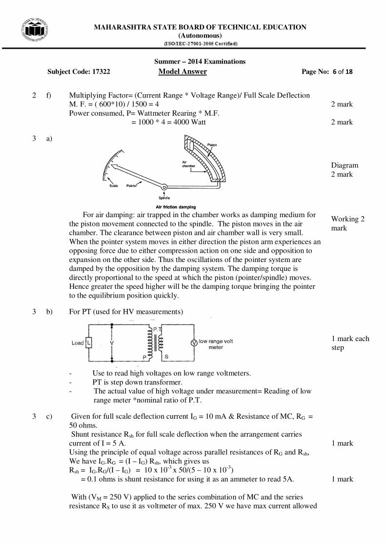
3 a)
For air damping: air trapped in the chamber works as damping medium for
the piston movement connected to the spindle. The piston moves in the air
chamber. The clearance between piston and air chamber wall is very small.
When the pointer system moves in either direction the piston arm experiences an
opposing force due to either compression action on one side and opposition to
expansion on the other side. Thus the oscillations of the pointer system are
damped by the opposition by the damping system. The damping torque is
directly proportional to the speed at which the piston (pointer/spindle) moves.
Hence greater the speed higher will be the damping torque bringing the pointer
to the equilibrium position quickly.
Diagram
2 mark
Working 2
mark
3 b) For PT (used for HV measurements)
- Use to read high voltages on low range voltmeters.
- PT is step down transformer.
- The actual value of high voltage under measurement= Reading of low
range meter *nominal ratio of P.T.
1 mark each
step
3 c) Given for full scale deflection current IG = 10 mA & Resistance of MC, RG =
50 ohms.
Shunt resistance Rsh for full scale deflection when the arrangement carries
current of I = 5 A.
Using the principle of equal voltage across parallel resistances of RG and Rsh,
We have IG.RG = (I – IG) Rsh, which gives us
Rsh = IG.RG/(I – IG) = 10 x 10-3
x 50/(5 – 10 x 10-3
)
= 0.1 ohms is shunt resistance for using it as an ammeter to read 5A.
With (VM = 250 V) applied to the series combination of MC and the series
resistance RS to use it as voltmeter of max. 250 V we have max current allowed
1 mark
1 mark

MAHARASHTRA STATE BOARD OF TECHNICAL EDUCATION
(Autonomous)
Summer – 2014 Examinations
Subject Code: 17322 Model Answer Page No: 7 of 18
of 10 mA.
250 V = 10 mA X (RS + RG) from which
RS = 25 X 103 – RG = 25 X 10
3 – 50 = 24950 ohms is series resistance for using
it as a voltmeter to read max 250V
1 mark
1 mark
3 d) Circuit diagram for reactive power measurement:
Vector diagram-
2mark
2 mark

MAHARASHTRA STATE BOARD OF TECHNICAL EDUCATION
(Autonomous)
Summer – 2014 Examinations
Subject Code: 17322 Model Answer Page No: 8 of 18
3 e) Block Diagram of Electronic Energy meter:
Functions of components/blocks:
- CT reduces current to reasonable value for current scaling network.
- Voltage & current scaling networks reduce proportionally the voltage &
current to values suitable for the analog multiplier.
- Analog multiplier gives a dc voltage proportional to the product of the
voltage and current drawn from supply that is the power drawn.
- The voltage controlled oscillator gives a frequency proportional to its input
(which is proportional to the power).
The ADC converts the square wave frequency analog output to display the energy
in watthour.
Labeled
diagram 2
marks,
Unlabeled 1
mark.
Any four ½
mark each =
2 marks
3 f) Explain working of clip on meter.
Clip on ammeters are used to measure the high current flowing through bus bar,
cable or fuse holders carrying currents. They consist of split core current
transformer whose secondary winding is connected to rectifier type moving coil
instrument. The primary become conductor, whose current is to be measured. The
split core gets aligned by the force of a spring tension. While the core is covered
with insulating material. Hence higher current through conductors can be
measured. A selector switch is provided to select secondary number of turns
which ultimately changes the current range. For measuring current the core is
opened by pressing trigger shown and then clipped over the conductor carrying
current. The dial will record the current directly.
Description
2 marks
Diagram 2
marks

MAHARASHTRA STATE BOARD OF TECHNICAL EDUCATION
(Autonomous)
Summer – 2014 Examinations
Subject Code: 17322 Model Answer Page No: 9 of 18
OR

MAHARASHTRA STATE BOARD OF TECHNICAL EDUCATION
(Autonomous)
Summer – 2014 Examinations
Subject Code: 17322 Model Answer Page No: 10 of 18
4 a) Advantages of MI instrument:
1. Universal use: These intruments can be used for both AC & DC
2. Less friction errors
3. Cheaper
4. Robust contruction
5. More accuracy
Disadvantages of MI instrument:
1. Scale is non uniform
2. Different calibrtions are needed for measurment of AC & DC quantities
3. Less sinsetiv as compared with PMMC type
4. The toque to weight ratio is less as compared with PMMC type.
Any two
Advantages
2 mark
Any two
Disadvant.
2 mark
4 b) Here Φ =cos -1
0.40
= 66.421
0
Total power=√3 * VL*IL *cos Φ
30000 watt=√3 * 500*IL *0.4
Therefore IL=86.5 amp
W1=V I cos (30+66.4210
) =500*86.5*cos(96.421)
and W2=V I cos (30-66.4210) =500*86.5*cos(-36.421)
W1= - 4836.78 watt
W2= 34802.69 W
1mark
1mark
1mark
1mark
4 c) Three phase four wire energy meter (Three element energy meter):

MAHARASHTRA STATE BOARD OF TECHNICAL EDUCATION
(Autonomous)
Summer – 2014 Examinations
Subject Code: 17322 Model Answer Page No: 11 of 18
4 d) Take reading of voltmeter and ammeter, then measured resistance = Rm =V/I
To minimise the error take 4 to 5 observation for the same resistance
2 mark
Diag. 2mark
4 e) Applications of digital multi-meter:
1. Measurement of DC voltage
2. Measurement of DC current
3. Measurement of AC voltage
4. Measurement of AC voltage
5. Measurement of resistance
6. Continuity testing
7. Testing of transistors
8. Measurement of frequency
9. Diode testing.
Eight
applications
½ mark each
4 f) Single phase dynamometer type power factor meter.
No controlling torque is required in this meter. Current flows in the pressure coil
through ligaments of silver. The coil A is connected in series with a non inductive
resistance R. So that current flowing through it is in phase with the applied
voltage. The coil B is connected in series with a highly inductive reactance L, so
that current flowing through it lags the voltage by 900.
The coil system of A and B takes up position of equilibrium where their torques
are equal. At this the angular position θ of A with respect to horizontal line is the
power factor angle Φ.
Diagram
2 marks
2 marks

MAHARASHTRA STATE BOARD OF TECHNICAL EDUCATION
(Autonomous)
Summer – 2014 Examinations
Subject Code: 17322 Model Answer Page No: 12 of 18
5 a) Megger is used to measure insulation resistance.
Labeled
Diag. 4
marks,
unlabeled 2
mark
5 b) The meter constant is 6000 revolutions per kWh
6000 rev =1kWh = 1000 watt hour
=1000*60*60 watt second
=3600000 watt second
Therefore 1 revolution = 3600000/6000 = 600 watt second
Hence 21 revolutions = 21 x 600 = 12600
= 12600 watt second has been recorded (registered).
Now power consumed= 110 x 2
= 220 watt
Energy to be actually recorded within 60 seconds will be (true value)
= 220 x 60
= 13200 watt second.
Therefore % error = {[true value – registered reading value]/true value} x 100
Therefore percentage error = [(13200 – 12600)/13200] x 100 = 4.54 %
1 mark
1 mark
1 mark
1 mark
5 c) The arrow marked on the disc represents the direction of rotation. If the phase
sequence of supply is same as that of the terminals marked on the indicator the
disc will rotate in the direction of rotation.
i)RYB: Direction of rotation clockwise
ii) BRY: Direction of rotation anti-clockwise.
2 marks
2 marks

MAHARASHTRA STATE BOARD OF TECHNICAL EDUCATION
(Autonomous)
Summer – 2014 Examinations
Subject Code: 17322 Model Answer Page No: 13 of 18
5 d) Working of LCR meter A LCR meter (Inductance (L), Capacitance (C), and Resistance
(R) test equipment used to measure the inductance, capacitance and, resistance of
a component. It works on the principle of impedance measurement.
In general versions of LCR meter, these quantities are not measured directly, but
determined from a measurement of impedance. The necessary calculations are,
incorporated in the instrument's circuitry; the meter reads L, C and R directly with
no human calculation required. It will determine the relative change in magnitude
of the repetitive variations of the voltage and current known as amplitudes.
Working –
- The device under test is subjected to an AC voltage source.
- The LCR meter detects the voltage over and the current through the device
under test.
- From the ratio of these, the meter can determine the magnitude of the
impedance.
- The phase angle between the voltage and current is also detected.
- The most useful assumption, and the one usually adopted, is that LR
measurements have the elements in series (as would be encountered
in an inductor coil) and that CR measurements have the elements in parallel (as
would be encountered in measuring a capacitor with a leaky dielectric).
- It can also be used to judge the inductance variation with respect to the
rotor position in permanent magnet machines.
- The full LCR meter test can be conducted very quickly depending on the
device tested.
OR
02 marks for
neat labeled
diagram
and
02 marks for
Working.

MAHARASHTRA STATE BOARD OF TECHNICAL EDUCATION
(Autonomous)
Summer – 2014 Examinations
Subject Code: 17322 Model Answer Page No: 14 of 18
Schering bridge
5 e) i) Fixed coil: Flux production- enameled copper winding coil.
ii) Moving iron: Force production due to magnetization- electromagnetic iron
piece.
iii) Iron Ring: Uniform flux distribution in space - electromagnetic iron
material.
iv) Control spring: To produce control torque – Phosphor bronze material.
½ mark for
function &
½ mark for
material
each
5 f) In two wattmeter method the reading of two wattmeters are given by equations-
W1=V I cos(30-Φ) and W2=V I cos (30+Φ)
We will consider different cases of power factors
i) If power factor is 0.5 lagging i.e.Φ= 600
W1=V I cos (30- 60) and W2=V I cos (30+60)
W1=V I cos(-30) and W2=V I cos (90)
W1=V I (-30) and W2=V I cos(0)
W1= (-30) and W2= V I cos 0
Thus it is observed that one of the wattmeter reads zero and all the
power is measured by other wattmeter.
ii) If power factor is 0 lag i.e. Φ= 900
W1=V I cos(30- 90) and W2=V I cos(30+ 90)
W1=V I cos-60 and W2=V I cos(120)
W1= -0.5* V I and W2=V I*(0.5)
Thus it is observed that both the wattmeter reads equal and opposite
power.
iii) If power factor is unity i.e. p.f.=1 (Φ=00)
W1=V I cos (30-0) and W2=V I cos (30+0)
W1=V I cos 30 and also W2=V I cos 30
Thus both the watt meters read equal readings.
iv) Pf = 0.4 lag.
If power factor is between 0.5 and 0. i.e. angle of lag is greater than 600
&
less than 90. In this case one of the wattmeter gives positive reading and
four cases
with effect
1mark each

MAHARASHTRA STATE BOARD OF TECHNICAL EDUCATION
(Autonomous)
Summer – 2014 Examinations
Subject Code: 17322 Model Answer Page No: 15 of 18
second wattmeter give negative reading.
Cos-1
0.4 = 66.42o.
W1=V I cos (30- 66.42) and W2=V I cos (30+ 66.42)
W1=V I cos(-36.42) and also W2=V I cos 96.42
One meter reads positive and other reads negative.
6 a) Gravity control method:
Controlling / restraining torque:
- To restrict the motion of pointer/spindle and stop the pointer at the
relevant position to get correct reading.
- To bring back pointer to zero position when the quantity under
measurement is removed.
- This is also provided by control weights shown in figure above.
Labeled
Diagram 2
marks,
Unlabeled 1
mark
2 marks
6 b) PMMC instrument can only measure D.C. quantities:
1. The direction of force exerted on moving coil depends on the direction of
current flowing through moving coil.
2. If the direction of magnetic field kept constant it produces unidirectional
torque. Thus the D.C. current is passed through the coil; unidirectional
torque is created as the direction of current is constant.
3. But in case of A.C. the direction of current reverses in the positive and
negative half cycle of A.C.
4. Hence force exerted on moving coil in positive half cycle acts in opposite
direction that will be the coil in negative half cycle.
5. Making the average torque acting on the coil in one cycle to zero. Hence the
meter cannot read A.C. quantities.
Any 4 pts. ½
mark each=
2 marks
6 c) - The purpose of calibration is to ensure that readings from an instrument
are consistent globally with other instruments. It is also important in determining
the accuracy of the instrument.
- Calibration needed for evaluating and adjusting the precision and accuracy
of measurement equipment. Instrument calibration is done to eliminate or reduce
error in an instrument's readings.
- Send the instrument for calibration after the test helps user decide whether
the data obtained were reliable and correct or not.
1 mark
1 mark

MAHARASHTRA STATE BOARD OF TECHNICAL EDUCATION
(Autonomous)
Summer – 2014 Examinations
Subject Code: 17322 Model Answer Page No: 16 of 18
- If instrument is kept idle for a long time, the instrument's conditions will
change, thus calibration in needed.
- Every instrument will need to be calibrated periodically to make sure it
can function properly and safely.
Standard meters:
- These meters are most accurate meters which are used for
calibration of meters. The permissible error in this meter is less than or equal to
0.2% .
1 mark
1 mark
6 d)
- Vertical amplifier strengthens the input signal applied to vertical depleting
plates
- Trigger circuit gives input to time base circuit
- The output of time base generator is amplified by horizontal amplifier and
then applied to horizontal deflecting plates of CRT
- CRT consists of electron gun assembly which include thermally heated
cathode, accelerating anode, focusing anode
- The electron beam coming out from electron gun assembly enters to
deflecting plates.
- The screen of CRT internally coated with Phosphors material on which we
observe waveform of the input signal.
Labeled
diag. 2
marks,
Unlabeled 1
mark
Function of
each Block 2
mark
6 e) Constructional details of ferro-dynamic type frequency meter. (Electrical
resonance type frequency meter)
Diagram 2
marks

MAHARASHTRA STATE BOARD OF TECHNICAL EDUCATION
(Autonomous)
Summer – 2014 Examinations
Subject Code: 17322 Model Answer Page No: 17 of 18
It consists of a fixed coil. The supply whose frequency is to be measured is
connected across it. This coil is also known as magnetizing coil. It is mounted on
a laminated iron core. The core has a typical varying cross section. It varies along
the length and is maximum at the end of core. The moving coil of it is pivoted
over this iron core. The pointer is fixed to the spindle and the terminals of moving
coil are connected to a suitable capacitor C .No controlling torque is required.
Working: - Current flowing through magnetizing coil produces flux in the iron
core which will set up an emf in the moving coil .This emf lags the flux Φ by
almost 900. This will cause current I to flow through capacitor C. If current is
inductive it will lag induced emf and a torque will act on the coil. If current is
capacitive then also the torque will act, but if the inductive reactance is equal to
capacitive reactance two torques will act on the moving coil. The capacitive
reactance is constant for given frequency but the inductive reactance depends
upon the position of pivoted coil on the core. The nearer the coil approaches the
magnetizing coil, the greater is it’s inductance .The moving coil is pulled towards
the magnetizing coil until both the reactances are exactly equal. i.e. when torque is
zero. The value of capacitor is so selected that the moving coil takes up a
convenient position when frequency is of normal value.
1mark
1mark
6 f) Function Generator:
• This instrument can deliver sine, triangular & square waves with
frequency range of 0.01 Hz to 100 kHz.
• The frequency control network is governed by a frequency dial on
the front panel of the instrument
• The frequency control voltage regulates two current sources.
• The upper current source supplies a constant current to the
integrator whose output voltage increases with time.
• The voltage comparator multi-vibrator changes state at a
predetermined level on the positive slope of the integrator’s output voltage.
• The lower current source supplies a reverse current to the integrator
so that its output voltage reaches a predetermined level on the negative slope of
the integrator’s output voltage.
Functions 2
marks (any
four blocks)
Labeled
diag. 2
marks,
Unlabeled 1
mark

MAHARASHTRA STATE BOARD OF TECHNICAL EDUCATION
(Autonomous)
Summer – 2014 Examinations
Subject Code: 17322 Model Answer Page No: 18 of 18