important instructions to examiners - information … is represented with a solid line connecting...
TRANSCRIPT
MAHARASHTRA STATE BOARD OF TECHNICAL EDUCATION
(Autonomous)
(ISO/IEC - 27001 - 2005 Certified)
SUMMER – 2016 EXAMINATION
Subject Code: 17630 Model Answer Page No: 1 /32
Important Instructions to examiners: 1) The answers should be examined by keywords and not as word-to-word as given in the model
answer scheme.
2) The model answer and the answer written by candidate may vary but the examiner may try to
assess the understanding level of the candidate.
3) The language errors such as grammatical, spelling errors should not be given more
importance. (Not applicable for subject English and Communication Skills).
4) While assessing figures, examiner may give credit for principal components indicated in the
figure. The figures drawn by candidate and model answer may vary. The examiner may give
credit for any equivalent figure drawn.
5) Credits may be given step wise for numerical problems. In some cases, the assumed constant
values may vary and there may be some difference in the candidate‟s answers and model answer.
6) In case of some questions credit may be given by judgment on part of examiner of relevant
answer based on candidate‟s understanding.
7) For programming language papers, credit may be given to any other program based on
equivalent concept.
Q 1. Attempt any FIVE of the following: 20 M
a) Write the importance of modeling.
(Relevant description of importance of modeling 4M)
Answer:
Modeling is a central part of all activities that lead up to the deployment of good software. It
is required to build quality software.
Importance of Modeling
Modeling gives graphical representation of system to be built.
Modeling contributes to a successful software organization.
Modeling is a proven and well accepted engineering technique.
Modeling is not just a part of the building industry. It would be inconceivable to
deploy a new aircraft or an automobile without first building models-from
computer models to physical wind tunnels models to full scale prototypes.
A model is a simplification of reality. A model provides the blueprint of a system.
A model may be structural, emphasizing the organization of the system, or it may
be behavioral, emphasizing the dynamics of the system.
Models are build for better understanding of the system that we are developing:
a. Models help us to visualize a system as it is or as we want it to be.
b. Models permit us to specify the structure or behavior of a system.

MAHARASHTRA STATE BOARD OF TECHNICAL EDUCATION
(Autonomous)
(ISO/IEC - 27001 - 2005 Certified)
SUMMER – 2016 EXAMINATION
Subject Code: 17630 Model Answer Page No: 2 /32
c. Models give us a template that guides us in constructing a system.
d. Models support the decisions we have made.
b) Define object and class. State how they are different and give suitable example of each.
(Definition of object-1M, Definition of class-1M, any one difference-1M, example ½ M
each)
Answer:
Definition of object:-
An object is a concept, abstraction or thing that has meaning for an application. Object is
basic run time entity.
Definition of class:-
A Class is a group of objects with similar properties (attributes), common behavior
(operation), common relationship to other objects and common semantics.
Difference:-
Class specifies properties, behavior, relationships and semantics that all the
objects of that class share where as object stores values for individual.
Class is a group of objects whereas object is an individual entity with unique
identity.
Example of class:-
STUDENT is a class. It specifies members as rollno.
Example of object:-
For class student: S1, S2, S3,….,Sn are objects.
c) Draw sequence diagram for student registration system.
(Correct sequence diagram showing registration process-4M: Any relevant diagram
shall be considered)
Answer:
S1:STUDENT
roll_no=1
STUDENT
roll_no:int

MAHARASHTRA STATE BOARD OF TECHNICAL EDUCATION
(Autonomous)
(ISO/IEC - 27001 - 2005 Certified)
SUMMER – 2016 EXAMINATION
Subject Code: 17630 Model Answer Page No: 3 /32
Assumption: - Student course registration
d) Draw and explain notations used for object diagram.
(Two notations: 2M each)
Answer:
1. Object: - An object is a concept, abstraction or thing that has meaning for an application.
Object is basic run time entity. In UML object is represented with a box including its
name followed by a colon and class name. Object and class name both are written in bold
face with underline.
Object can have attributes. Attributes are specified in the second part of the block.
Attribute name is followed by value.
Notation Example
Object_name:Class_name
attribute_name=value
S1:STUDENT
roll_no=1
MAHARASHTRA STATE BOARD OF TECHNICAL EDUCATION
(Autonomous)
(ISO/IEC - 27001 - 2005 Certified)
SUMMER – 2016 EXAMINATION
Subject Code: 17630 Model Answer Page No: 4 /32
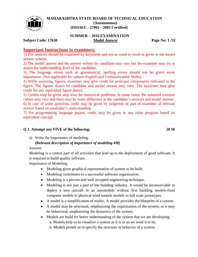
2. Link- It is physical or conceptual connection among objects. It is used to show
relationship among objects. It is represented with a solid line connecting two objects.
Name of the link is written in italic form above line.
Link name
Example:-
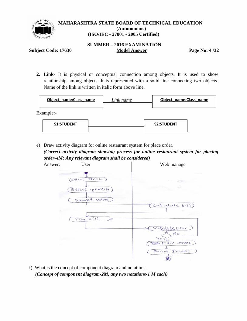
e) Draw activity diagram for online restaurant system for place order.
(Correct activity diagram showing process for online restaurant system for placing
order-4M: Any relevant diagram shall be considered)
Answer: User Web manager
f) What is the concept of component diagram and notations.
(Concept of component diagram-2M, any two notations-1 M each)
Object_name:Class_name Object_name:Class_name
S1:STUDENT S2:STUDENT

MAHARASHTRA STATE BOARD OF TECHNICAL EDUCATION
(Autonomous)
(ISO/IEC - 27001 - 2005 Certified)
SUMMER – 2016 EXAMINATION
Subject Code: 17630 Model Answer Page No: 5 /32
Answer:
A component diagram shows the organization and dependencies among a set of components.
Component diagram addresses the static implementation view of a system. It specifies set of
components and their relationships. It involves modeling the physical things that reside on a
node are represented as component such as executables, libraries, tables, files and documents.
Notations of Component Diagram:
1. Component: - A component is a physical and replaceable part of the system that accesses and
provides set of interfaces. It is represented as a rectangle with tabs, usually including only its
name. A component icon is a rectangle with two smaller rectangles jutting out from left-hand
side.
2. Interface:-An interface is a collection of operations that are used to specify service of a
component. It is represented with a circle or semi circle.
3. Port: - A port specifies an interaction point through which a component can communicate
with its environment, other components or with its internal parts. Port is represented using a
square along the edge of the system or a component.

MAHARASHTRA STATE BOARD OF TECHNICAL EDUCATION
(Autonomous)
(ISO/IEC - 27001 - 2005 Certified)
SUMMER – 2016 EXAMINATION
Subject Code: 17630 Model Answer Page No: 6 /32
4. Connector: - It is a link that specifies communication between two or more classifiers.
Delegation connector is used to connect internal parts of component with the interface provided
by component. Assembly connector shows that a component requires an interface that another
component provides.
Or
5. Artifact: - An artifact is a physical file that executes or used by the software. It includes
executable files, library files, source files and configuration files.
Q 2. Attempt any FOUR of the following: 16 M
a) Give any four principles of modeling.
(4 Principles :- 1M each)

MAHARASHTRA STATE BOARD OF TECHNICAL EDUCATION
(Autonomous)
(ISO/IEC - 27001 - 2005 Certified)
SUMMER – 2016 EXAMINATION
Subject Code: 17630 Model Answer Page No: 7 /32
Answer:
1. The choice of what models to create has a profound influence on how a problem is attacked
and how a solution is shaped.
2. Every model may be expressed at different levels of precision.
3. The best models are connected to reality.
4. No single model is sufficient. Every nontrivial system is best approached through a small set
of nearly independent models.
b) What is meaning of:
(i) Attributes
(ii) Link attributes with reference to class and object.
(Meaning of attributes 2M, link attributes 2M)
Answer:
(i) Attributes: - An attributes is a named property of a class that describes a value held by each
object of the class. A class may have any number of attributes or no attributes at all. An attribute
represents some property of the thing that is shared by all the objects of that class.
Attributes are listed in the second part of Class Box. Each attribute name may be
followed by optional details. Each attribute name is Unique within a class.
For Example: Class Person has attributes Name, Birthdate and weight. Name is string,
Birthdate is Date and Weight is integer.
(ii). link attributes with reference to class and object:- Link attribute allow adding properties to
association between two classes/objects.
For example: In the below example company and person has a link/association between them
which has link attributes as description, datehired and salary. These attributes are placed inside
the association class job. Association class is linked to association line with dashed line.

MAHARASHTRA STATE BOARD OF TECHNICAL EDUCATION
(Autonomous)
(ISO/IEC - 27001 - 2005 Certified)
SUMMER – 2016 EXAMINATION
Subject Code: 17630 Model Answer Page No: 8 /32
c) State the importance of use case diagram.
(Any relevant description of importance of use case diagram 4M)
Answer:
Use case diagram:-
It shows a set of use cases and actors and their relationships. a use case is a description of a set of
sequences of actions that a system performs to get an result to tan actor. It describes a set of
sequences in which each sequence represents the interaction of the things outside the system with
the system itself. It represents functional requirements of system. For example, for ATM system
validating pin for the customer is a behavior of a system which can be shown as use case.
It addresses the static use case view of a system. These are important in organizing and modeling
the behaviors of a system.
Common uses of use case diagram:-
To model the context of a system:- modeling the context of a system involves drawing a
line around the system and representing actors lie outside the system and interact with it.
In use case diagram actors and the meaning of their roles is represented.
To model the requirements of a system:-modeling the requirements of a system involves
specifying what that system should do without respect to how that system should do it.
Notations:-
Use case: - It is shown with ellipse.
Association: - It is shown with solid line.

MAHARASHTRA STATE BOARD OF TECHNICAL EDUCATION
(Autonomous)
(ISO/IEC - 27001 - 2005 Certified)
SUMMER – 2016 EXAMINATION
Subject Code: 17630 Model Answer Page No: 9 /32
d) What is behavioral modeling.
(Any relevant description of behavioral modeling 4M)
Answer:-
Behavioral modeling: - It indicates how software will respond to external events or stimuli. In
behavioral model, the behavior of the system is represented as a function of specific events and
time.
To create behavioral model following things can be considered:
Evaluation of all use-cases to fully understand the sequence of interaction within the
system.
Identification of events that drive the interaction sequence and understand how these
events relate to specific classes.
Creating sequence for each use case.
Building state diagram for the system.
Reviewing the behavioral model to verify accuracy and consistency.
It describes interactions between objects. It shows how individual objects collaborate to achieve
the behavior of the system as a whole. In UML behavior of a system is shown with the help of
use case diagram, sequence diagram and activity diagram
A use case focuses on the functionality of a system i.e. what a system does for users. It
shows interaction between the system and outside actors.
Ex: Student, librarians are actors, issue book use case.
A sequence diagram shows the objects that interact and the time sequence of their
interactions.
Ex: Student, librarians are objects. Time sequence enquires for book check availability –
with respect time.
An activity diagram specifies important processing steps. It shows operations required for
processing steps. It shows operations required for processing.
Ex issue book, check availability does not show objects
e) Describe the concept of concurrent sub-state with respect to state diagram.
(Description of concurrent state with example 4M)
Answer:
Concurrent state diagram shows a set of independent behaviors of an object. Concurrent sub
states are independent and can execute in parallel. A state may be divided into regions containing
sub-states that exist and execute concurrently.

MAHARASHTRA STATE BOARD OF TECHNICAL EDUCATION
(Autonomous)
(ISO/IEC - 27001 - 2005 Certified)
SUMMER – 2016 EXAMINATION
Subject Code: 17630 Model Answer Page No: 10 /32
UML shows concurrency within an object by partitioning the composite / state into
regions with dotted lines.
Example:-
In the above example, concurrent sub states are shown. Maintenance is a composite state. It is
decomposed into two concurrent sub-states as testing and commanding. Each of these concurrent
sub-states is further decomposed into sequential sub-states. When control passes from Idle to
Maintenance state, control then forks to two concurrent flows. Execution of these two concurrent
sub-states continues parallel in the system. Each nested state machine reaches its final state. If
one concurrent sub state reaches its final state before the other, then control in that sub-state
waits at its final state. When both nested state reaches their final state, control from the two
concurrent sub-states joins back into one flow.
f) Explain <<include>> and <<extend>> dependencies used in use case diagrams.
(Description of <<include>> 2M, <<extend>> 2M)
Answer:
<<include>> relationships: Include relationship is used to include one use case within the
behavior sequence of another use case.
An include relationship between use cases means that the base case explicitly
incorporates the behavior of another use case at a location specified in the base.
The include use case never stand alone. When an actor initiates any base use case then
base use case executes included use case.
An include relationship as a dependency can be render with stereotyped as include. To
specify the location in a flow of events in which the base use case includes the behavior
of another, simply write include followed by the name of the use case.
MAHARASHTRA STATE BOARD OF TECHNICAL EDUCATION
(Autonomous)
(ISO/IEC - 27001 - 2005 Certified)
SUMMER – 2016 EXAMINATION
Subject Code: 17630 Model Answer Page No: 11 /32
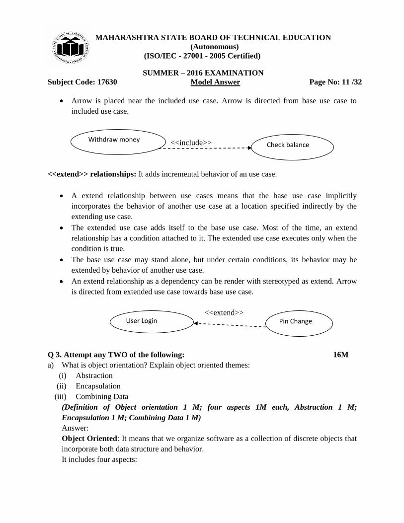
Arrow is placed near the included use case. Arrow is directed from base use case to
included use case.
<<include>>
<<extend>> relationships: It adds incremental behavior of an use case.
A extend relationship between use cases means that the base use case implicitly
incorporates the behavior of another use case at a location specified indirectly by the
extending use case.
The extended use case adds itself to the base use case. Most of the time, an extend
relationship has a condition attached to it. The extended use case executes only when the
condition is true.
The base use case may stand alone, but under certain conditions, its behavior may be
extended by behavior of another use case.
An extend relationship as a dependency can be render with stereotyped as extend. Arrow
is directed from extended use case towards base use case.
<<extend>>
Q 3. Attempt any TWO of the following: 16M
a) What is object orientation? Explain object oriented themes:
(i) Abstraction
(ii) Encapsulation
(iii) Combining Data
(Definition of Object orientation 1 M; four aspects 1M each, Abstraction 1 M;
Encapsulation 1 M; Combining Data 1 M)
Answer:
Object Oriented: It means that we organize software as a collection of discrete objects that
incorporate both data structure and behavior.
It includes four aspects:
Check balance Withdraw money
User Login Pin Change

MAHARASHTRA STATE BOARD OF TECHNICAL EDUCATION
(Autonomous)
(ISO/IEC - 27001 - 2005 Certified)
SUMMER – 2016 EXAMINATION
Subject Code: 17630 Model Answer Page No: 12 /32
1. Identity: - It means that data is quantized into discrete, distinguishable entities called
object. Objects can be concrete, such as a file system, or conceptual such as scheduling
policy in multiprocessing operating system. Each object has its inherent identity.
2. Classification: - objects with the same data structure (attributes) and behavior
(operations) are grouped into a class. A class is an abstraction that describes properties
important to an application and ignores the rest.
3. Inheritance: - It is sharing of attributes and operations (features) among classes based on
hierarchical relationships. A super class has information that its sub classes refine and
elaborate.
4. Polymorphism: - It means that the same operation may behave differently for different
classes. The move operation behaves differently for the pawn than for the queen in a
chess game.
Object oriented themes:-
(i) Abstraction: - It means focusing on the essential aspects of an entity while ignoring its
details. This means focusing on what an object is and does, before deciding how it should be
implemented. Use of abstraction during analysis means dealing only with application
domain concepts, not making decisions before problem is understood.
(ii) Encapsulation:- It means information hiding. It consists of separating the external
aspects of an object, which are accessible to other objects, from internal implementation
details of the object, which are hidden from other objects. It prevents program from
becoming so interdependent that a small change has massive ripple effect. It gives the ability
to combine data structure and behavior in a single entity.
(iii)Combining Data:- The burden of calling code for data execution and operations
separately can be minimized by combining data properties and behavioral properties of an
entity together. In object oriented program data structure and procedure is defined in single
class definition.
b) Draw use case diagram for railway ticket counter (Use railway ticket counter, booking
clerk)
(Correct Use case Diagram 8M; Any relevant diagram shall be considered)
Answer:

MAHARASHTRA STATE BOARD OF TECHNICAL EDUCATION
(Autonomous)
(ISO/IEC - 27001 - 2005 Certified)
SUMMER – 2016 EXAMINATION
Subject Code: 17630 Model Answer Page No: 13 /32
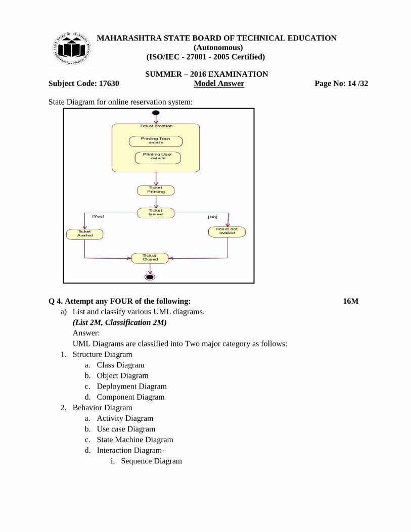
c) Draw activity and state diagram for online reservation system.
(Activity Diagram 4 M; State Diagram 4 M; any relevant diagram shall be considered)
Answer:
Customer or
Counter Booking Clerk
Book Ticket
Make Payment
Book Pass
Extension Ticket
Cancel Ticket
MAHARASHTRA STATE BOARD OF TECHNICAL EDUCATION
(Autonomous)
(ISO/IEC - 27001 - 2005 Certified)
SUMMER – 2016 EXAMINATION
Subject Code: 17630 Model Answer Page No: 14 /32
State Diagram for online reservation system:
Q 4. Attempt any FOUR of the following: 16M
a) List and classify various UML diagrams.
(List 2M, Classification 2M)
Answer:
UML Diagrams are classified into Two major category as follows:
1. Structure Diagram
a. Class Diagram
b. Object Diagram
c. Deployment Diagram
d. Component Diagram
2. Behavior Diagram
a. Activity Diagram
b. Use case Diagram
c. State Machine Diagram
d. Interaction Diagram-
i. Sequence Diagram
MAHARASHTRA STATE BOARD OF TECHNICAL EDUCATION
(Autonomous)
(ISO/IEC - 27001 - 2005 Certified)
SUMMER – 2016 EXAMINATION
Subject Code: 17630 Model Answer Page No: 15 /32
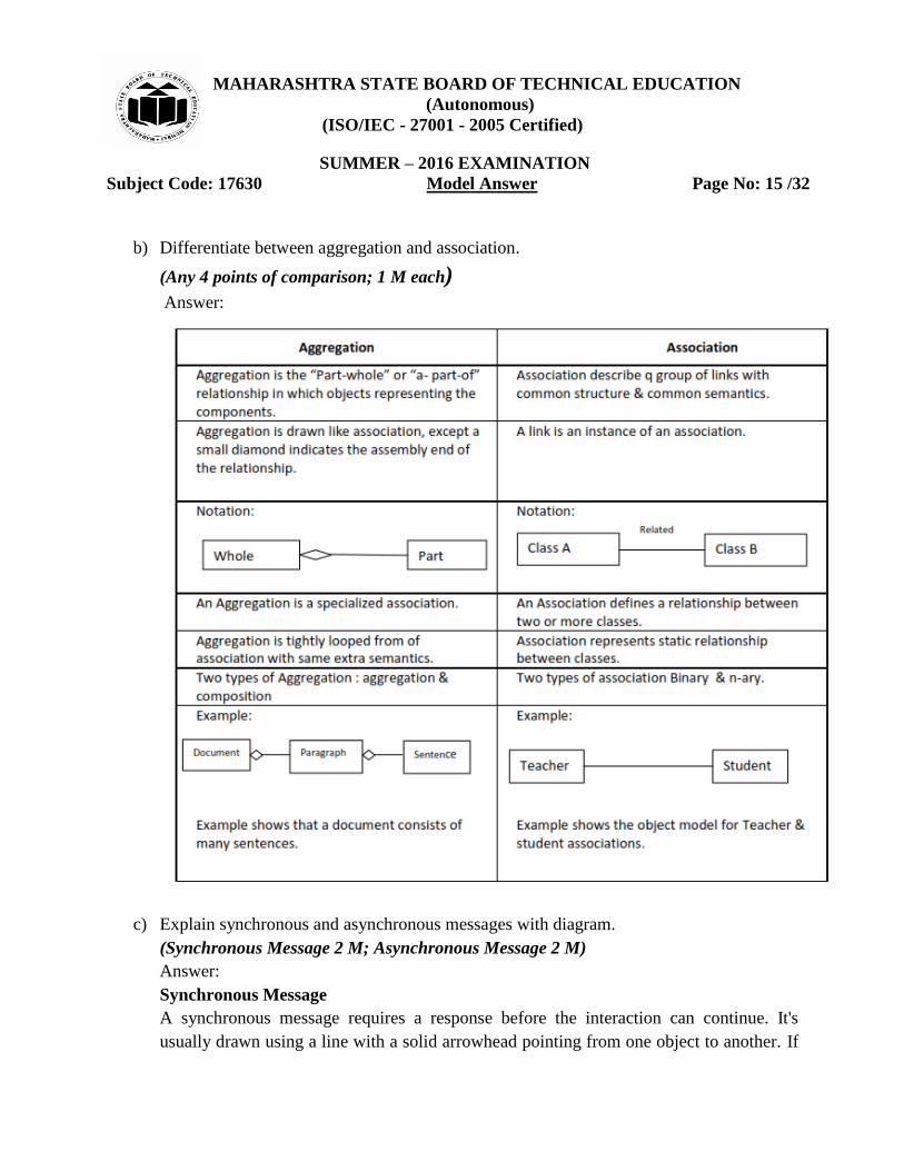
b) Differentiate between aggregation and association.
(Any 4 points of comparison; 1 M each) Answer:
c) Explain synchronous and asynchronous messages with diagram.
(Synchronous Message 2 M; Asynchronous Message 2 M)
Answer:
Synchronous Message
A synchronous message requires a response before the interaction can continue. It's
usually drawn using a line with a solid arrowhead pointing from one object to another. If
MAHARASHTRA STATE BOARD OF TECHNICAL EDUCATION
(Autonomous)
(ISO/IEC - 27001 - 2005 Certified)
SUMMER – 2016 EXAMINATION
Subject Code: 17630 Model Answer Page No: 16 /32
a caller sends a synchronous message, it must wait until the message is done, such as
invoking a subroutine.
Asynchronous Message
Asynchronous messages don't need a reply for interaction to continue. Like synchronous
messages, they are drawn with an arrow connecting two lifelines; however, the
arrowhead is usually open and there's no return message depicted. If a caller sends an
asynchronous message, it can continue processing and doesn‟t have to wait for a
response.
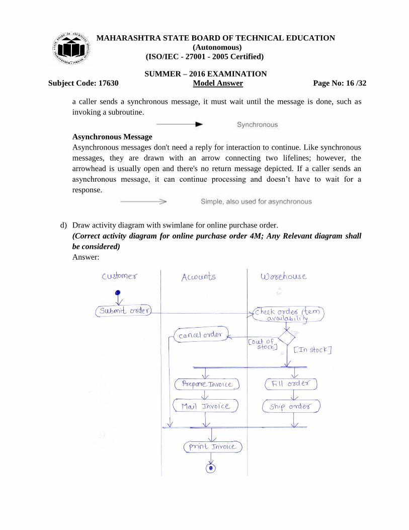
d) Draw activity diagram with swimlane for online purchase order.
(Correct activity diagram for online purchase order 4M; Any Relevant diagram shall
be considered)
Answer:

MAHARASHTRA STATE BOARD OF TECHNICAL EDUCATION
(Autonomous)
(ISO/IEC - 27001 - 2005 Certified)
SUMMER – 2016 EXAMINATION
Subject Code: 17630 Model Answer Page No: 17 /32
e) What is meant by architectural modelling?
(Description 2 M; Diagram 2M)
Answer:
Architectural model is used for Visualizing, specifying, constructing, and documenting a
software-intensive system.
Architecture is the set of significant decisions about:
The organization of a software system
The selection of the structural elements and their interfaces by which the system
is composed.
Their behavior, as specified in the collaborations among those elements.
The composition of these structural and behavioral elements into progressively
larger subsystems.
The architectural style that guides their organization: the static and dynamic
elements and their interfaces, their collaborations, and their composition.
a. The use case view of a system encompasses the use cases that describe the behavior
of the system as seen by its end users, analysts, and testers.
b.The design view of a system encompasses the classes, interfaces, and collaborations
that form the vocabulary of the problem and its solution.
MAHARASHTRA STATE BOARD OF TECHNICAL EDUCATION
(Autonomous)
(ISO/IEC - 27001 - 2005 Certified)
SUMMER – 2016 EXAMINATION
Subject Code: 17630 Model Answer Page No: 18 /32
c. The process view of the system encompasses the threads and processes that form
the systems concurrency and synchronization mechanisms.
d. The implementation view of a system encompasses the components and files that
are used to assemble and release the physical system.
e. The deployment view of a system encompasses the nodes that form the system‟s
hardware topology on which the system executes.
f) Draw and explain notations used in activity diagram.
(Any 4 Notations – 1 M each)
Answer:
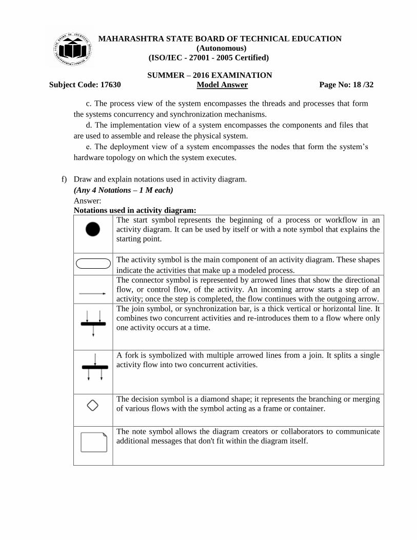
Notations used in activity diagram:
The start symbol represents the beginning of a process or workflow in an
activity diagram. It can be used by itself or with a note symbol that explains the
starting point.
The activity symbol is the main component of an activity diagram. These shapes
indicate the activities that make up a modeled process.
The connector symbol is represented by arrowed lines that show the directional
flow, or control flow, of the activity. An incoming arrow starts a step of an
activity; once the step is completed, the flow continues with the outgoing arrow.
The join symbol, or synchronization bar, is a thick vertical or horizontal line. It
combines two concurrent activities and re-introduces them to a flow where only
one activity occurs at a time.
A fork is symbolized with multiple arrowed lines from a join. It splits a single
activity flow into two concurrent activities.
The decision symbol is a diamond shape; it represents the branching or merging
of various flows with the symbol acting as a frame or container.
The note symbol allows the diagram creators or collaborators to communicate
additional messages that don't fit within the diagram itself.

MAHARASHTRA STATE BOARD OF TECHNICAL EDUCATION
(Autonomous)
(ISO/IEC - 27001 - 2005 Certified)
SUMMER – 2016 EXAMINATION
Subject Code: 17630 Model Answer Page No: 19 /32
The end symbol represents the completion of a process or workflow.
Q 5. Attempt any FOUR of the following. 16M
a) Explain Rambaugh OMT in detail.
(Relevant Explanation with four stages: each 1M)
Answer:
OMT by Ram Baugh
Object Modeling Technique (OMT) includes four stages:-
1. Analysis:- Starting from a statement of the problem, the analyst builds a model of the
real-world situation showing its important properties. The analyst works with the
requestor to understand the problem statement. The analysis model is a concise, precise
abstraction of what the desired system must do, not how it will be done. A good model
can be understood and criticized by application experts who are not programmers. The
analysis model does not contain any implementation details.
2. System Design: - System designer makes high level decisions about the overall
architecture. During system design, the target system is organized into subsystems based
on both the analysis structure and the proposed architecture. The system designer decides
what performance characteristics to optimize, choose a strategy of attacking the problem
and make tentative resource allocations.
3. Object Design: - The object designer builds a design model based on the analysis model
but contains implementation details. The designer adds details to the design model in
accordance with the strategy established during system design. The focus of object design
is the data structures and algorithms needed to implement each class.
4. Implementation: - The object classes and relationships developed during object design
are finally translated into a particular programming language, database or hardware
implementation. During implementation, it is important to follow good software
engineering practice do that traceability to the design is straightforward and so that the
implemented system remains flexible and extensible.
b) Define multiplicity and qualification with appropriate example.
(Description of Multiplicity with example 2M, Description of Qualification with
example 2M)

MAHARASHTRA STATE BOARD OF TECHNICAL EDUCATION
(Autonomous)
(ISO/IEC - 27001 - 2005 Certified)
SUMMER – 2016 EXAMINATION
Subject Code: 17630 Model Answer Page No: 20 /32
Answer:
Multiplicity
Multiplicity specifies the number of instances of one class that may relate to a single
instance of an associated class. The UML specifies multiplicity as follows:
Notations:
1. ”1” exactly one
2. “1…*” One or more
3. “3-5” three to five
4. 0..1 zero to one
5. “2,4,18” two, four or eighteen
6. Symbol * denotes “many”
Example:
Qualification:
Qualification specifies relation between two object classes and a qualifier. The qualifier
is a special attribute that reduces the effective multiplicity of an association. The qualifier

MAHARASHTRA STATE BOARD OF TECHNICAL EDUCATION
(Autonomous)
(ISO/IEC - 27001 - 2005 Certified)
SUMMER – 2016 EXAMINATION
Subject Code: 17630 Model Answer Page No: 21 /32
distinguishes among the set of objects at the many end of an association. A qualifier is
drawn as a small box on the end of the association line near the class it qualifies.
Notation
Example:
c) Explain with diagram create & destroy messages.
(Description of create message with diagram 2M, Description of destroy message with
diagram 2M)
Answer:
create message
1. Objects can be created according to the requirement of the system in between the
processing of the system because they are not required for the entire duration of the
sequence diagram‟s interaction.
2. If an object does not exist at the beginning of a sequence diagram then it must be
created in the system.
3. The UML shows creation by placing the object notation at the head of the arrow for the
message call that creates an object.
destroy message
1. An object can destroy itself or it can be destroyed by other objects of the sequence
diagram because those objects may not further require during the system.
2. If the object is destroyed by itself then „X‟ is placed at the head of the call arrow that
destroys the object.
3. If the object destroys and returns control to another object then „X‟ is placed at the tail
of the return arrow.

MAHARASHTRA STATE BOARD OF TECHNICAL EDUCATION
(Autonomous)
(ISO/IEC - 27001 - 2005 Certified)
SUMMER – 2016 EXAMINATION
Subject Code: 17630 Model Answer Page No: 22 /32
Example:
d) Explain forking and joining with diagram.
(Relevant explanation of forking with diagram 2M, joining with diagram 2M)
Answer:
Forking in Activity diagram:
1. A fork in activity diagram represents the splitting of a single flow of control into two or
more concurrent flows of control.
2. A fork may have one incoming transition and two or more outgoing transitions, each of
which represents an independent flow of control.
3. Below the fork, the activities associated with each of these paths continue in parallel.
Joining in Activity diagram:
1. A join in Activity diagram represents the synchronization of two or more concurrent
flows of control.
2. A join may have two or more incoming transitions and one outgoing transition.
3. Above the join, activities associated with each of these paths continue in parallel.
4. At the join, the concurrent flows synchronize, means each waits until all incoming flows
have reached at the join, at which point one flow of control continues on below the join.

MAHARASHTRA STATE BOARD OF TECHNICAL EDUCATION
(Autonomous)
(ISO/IEC - 27001 - 2005 Certified)
SUMMER – 2016 EXAMINATION
Subject Code: 17630 Model Answer Page No: 23 /32
Example:
e) Explain concept of interface and ports.
(Relevant explanation of interfaces 2M, ports 2M)
Answer:
Interface
A component can be connected with other components through interfaces. An interface i.e.
small circle or semi-circle on a stick describes a group of operations used (required) or created
(provided) by components. A full circle represents an interface created or provided by the
component. A semi-circle represents a required interface, like a person's input.

MAHARASHTRA STATE BOARD OF TECHNICAL EDUCATION
(Autonomous)
(ISO/IEC - 27001 - 2005 Certified)
SUMMER – 2016 EXAMINATION
Subject Code: 17630 Model Answer Page No: 24 /32
Ports:
Ports are represented using a square along the edge of the system or a component. A port is
often used to help expose required and provided interfaces of a component.
f) What are constraints? How they are applied?
(Description of constraint: 2M, any two constraints application 1M each)
Answer:
Constraints:
Constraint is a boolean condition involving model elements such as objects, classes,
attributes, links and associations. A constraint restricts the values that entities/elements
can assume.
1. Constraints on Objects:
The structure of model expresses many constraints but sometimes it is helpful to add
explicit constraints. Examples of some constraints are:
2. Constraints on Generalization Sets:
Disjoint
Overlapping
Complete
Incomplete

MAHARASHTRA STATE BOARD OF TECHNICAL EDUCATION
(Autonomous)
(ISO/IEC - 27001 - 2005 Certified)
SUMMER – 2016 EXAMINATION
Subject Code: 17630 Model Answer Page No: 25 /32
3. Constraints on Links:
Q 6. Attempt any FOUR of the following. 16M
a) Describe rational unified software development life cycle with its all phases.
(Description of software development life cycle with four correct phases and diagram:
4M)
Answer:
The UML is largely process independent i.e it is not any particular software development
life cycle. However, to get the most benefit from the UML, you should consider a process
that is:

MAHARASHTRA STATE BOARD OF TECHNICAL EDUCATION
(Autonomous)
(ISO/IEC - 27001 - 2005 Certified)
SUMMER – 2016 EXAMINATION
Subject Code: 17630 Model Answer Page No: 26 /32
use case driven
Architecture centric
Iterative and incremental
Below fig shows 4 phases in the SDLC:
1. Inception
It is the first phase of the process, when the seed idea for the development is
brought up.
2. Elaboration
It is the second phase of the process, when the product vision and its architecture
are defined. In this phase, the system‟s requirements are articulated, prioritized
and baselined.
3. Construction
It is the third phase of the process, when the software is brought from an
executable architectural baseline to being ready to be transitioned to the user
community.
4. Transition
It is the fourth phase of the process, when the software is turned into the hands of
the user community.
Fig: Software Development Life Cycle
MAHARASHTRA STATE BOARD OF TECHNICAL EDUCATION
(Autonomous)
(ISO/IEC - 27001 - 2005 Certified)
SUMMER – 2016 EXAMINATION
Subject Code: 17630 Model Answer Page No: 27 /32
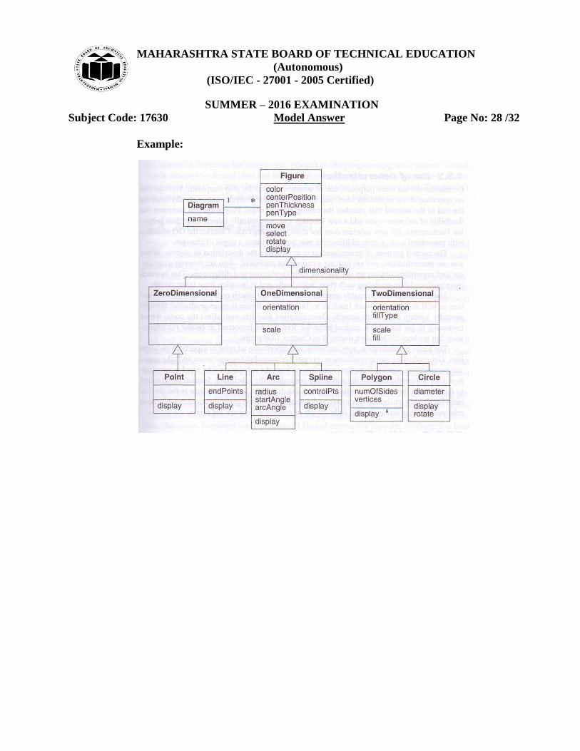
b) Explain generalization and inheritance.
(Relevant explanation of Generalization and Inheritance with relevant example 4M)
Answer:
Generalization and Inheritance:
1. Generalization is a relationship between a class and one or more derived classes
of it.
2. Generalization organizes classes by their similarities & differences, structuring
the description of objects.
3. The class being derived is called as super class and its derived classes are called
as subclasses.
4. Each subclass is said to “inherit” the features of superclass. This property is called
as inheritance.
5. The superclass holds common attributes, operations and association; the
subclasses add specific attributes, operations & associations
6. It is also called as is-a relationship because each instance of a subclass is an
instance of the super class as well.
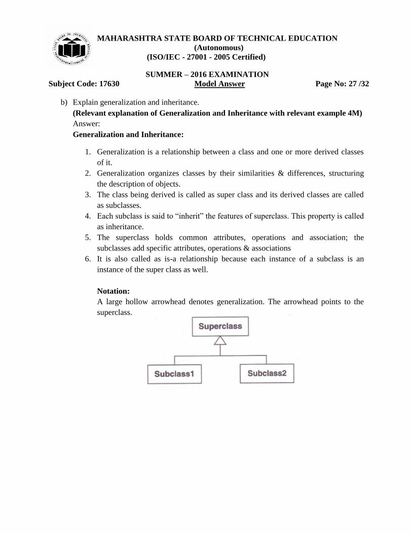
Notation:
A large hollow arrowhead denotes generalization. The arrowhead points to the
superclass.
MAHARASHTRA STATE BOARD OF TECHNICAL EDUCATION
(Autonomous)
(ISO/IEC - 27001 - 2005 Certified)
SUMMER – 2016 EXAMINATION
Subject Code: 17630 Model Answer Page No: 28 /32
Example:
MAHARASHTRA STATE BOARD OF TECHNICAL EDUCATION
(Autonomous)
(ISO/IEC - 27001 - 2005 Certified)
SUMMER – 2016 EXAMINATION
Subject Code: 17630 Model Answer Page No: 29 /32
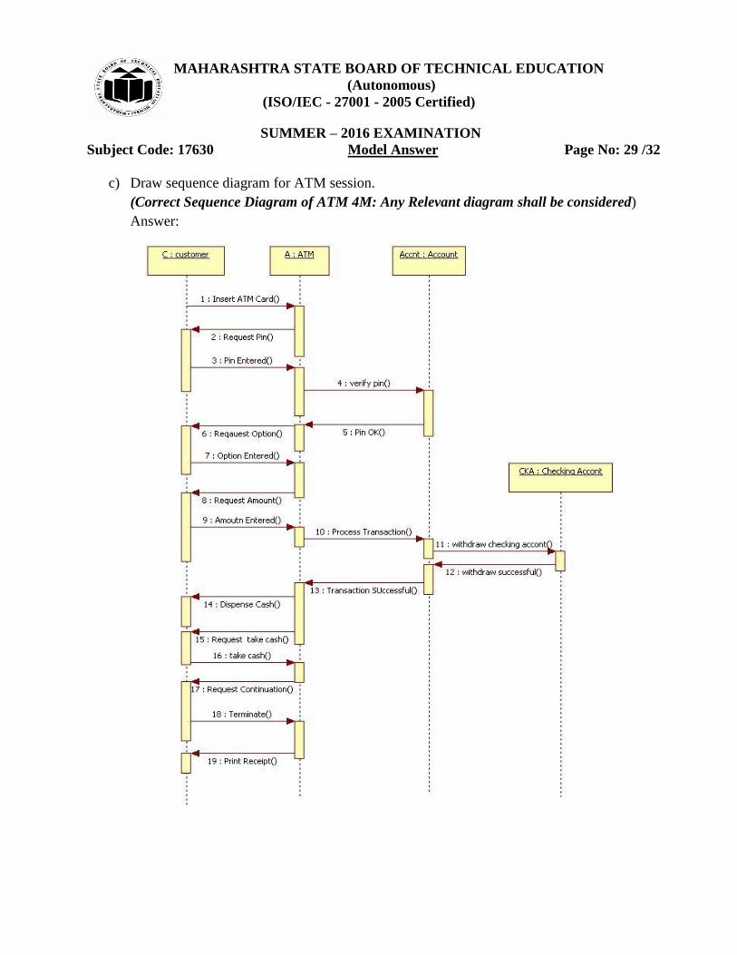
c) Draw sequence diagram for ATM session.
(Correct Sequence Diagram of ATM 4M: Any Relevant diagram shall be considered)
Answer:

MAHARASHTRA STATE BOARD OF TECHNICAL EDUCATION
(Autonomous)
(ISO/IEC - 27001 - 2005 Certified)
SUMMER – 2016 EXAMINATION
Subject Code: 17630 Model Answer Page No: 30 /32
d) Enlist various notations in state diagram. Explain state.
(Any three correct notations of state diagram 1M each, Explanation of state 1M)
Answer:
A state is a condition or a situation in the life of an object during which it satisfies some
conditions, performs some activity or waits for some events. It is represented with a
rounded rectangle. Name of the state is written inside the rectangle.
Various notations in State diagram are:
Sr No Name Symbol
1 State
2 Initial state
3 Final state
4 Transition
5 Event
6 Action
Event
Event/action

MAHARASHTRA STATE BOARD OF TECHNICAL EDUCATION
(Autonomous)
(ISO/IEC - 27001 - 2005 Certified)
SUMMER – 2016 EXAMINATION
Subject Code: 17630 Model Answer Page No: 31 /32
e) Sketch component diagram for order processing.
(Correct component diagram for order processing 4M: Any Relevant diagram shall be
considered)
Answer:
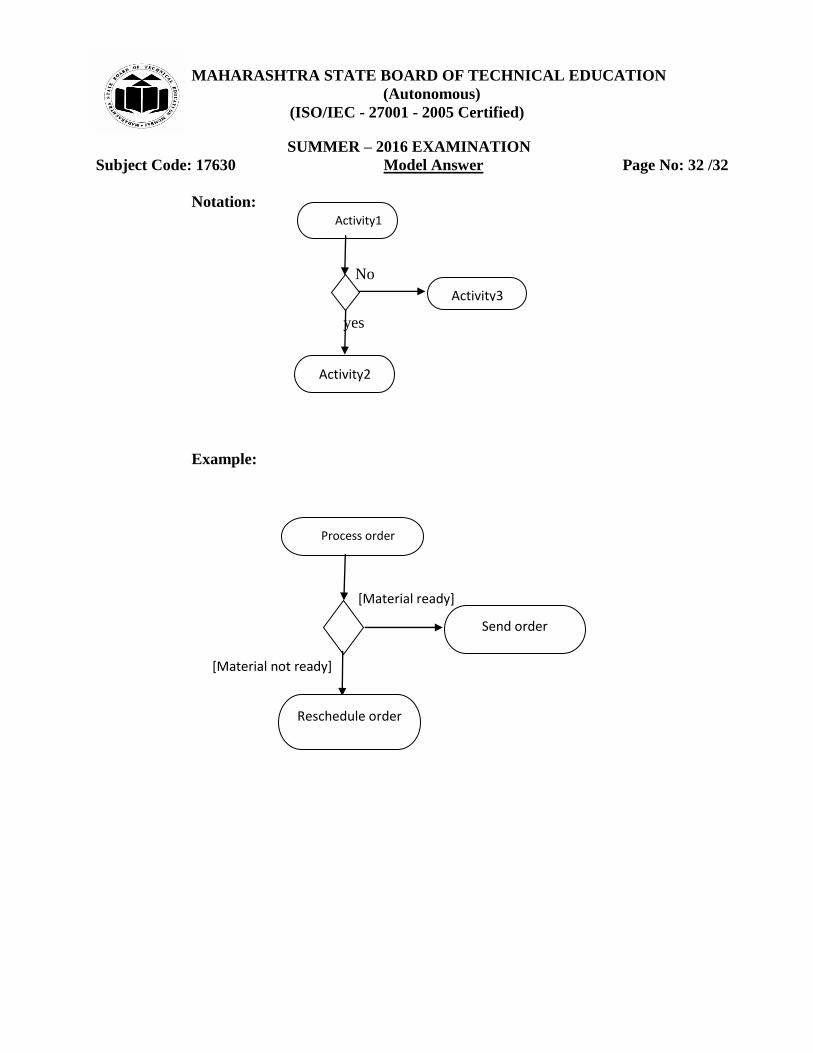
f) Explain decision making and branching in activity diagram.
(Relevant explanation with example 4M)
Answer:
Decision Making and Branching:
1. In an activity diagram, Diamond Shape is used for Decision and branches are
represented by lines. The condition written in diamond is the decision criteria.
2. A branch may have one incoming transition and two or more outgoing ones.
3. On each outgoing transition, we place a Boolean expression, which is evaluated
only once on entering the branch.
4. We can use the keyword else to mark one outgoing transition, representing the
path taken if no other guard expression evaluate to true.
5. When two paths of control merge back together, we can also use a diamond
symbol with two input arrow and one output arrow. No guards are necessary on
merge.
MAHARASHTRA STATE BOARD OF TECHNICAL EDUCATION
(Autonomous)
(ISO/IEC - 27001 - 2005 Certified)
SUMMER – 2016 EXAMINATION
Subject Code: 17630 Model Answer Page No: 32 /32
Notation:
No
yes
Example:
[Material ready]
[Material not ready]
Activity1
Activity2
Activity3
Process order
Reschedule order
Send order