implementing the x-lock-3 on the heathkit hw-101 the x lock in the hw-101.pdf · 2012-04-30 ·...
TRANSCRIPT

Implementing the X-Lock-3 on the Heathkit HW-101
Pete Juliano, N6QW [email protected]
I had previously installed the X-Lock-2 in a Ten Tec Corsair I and a TR-7. SubsequentlyI installed an X-Lock-3 in a second TR-7. I guess you can say I am hooked! Recently Igot the urge to try updating and remodeling a Heathkit HW-101 SSB/CW Transceiver.That effort entailed replacing many components and making some of the well-documented improvements. To add a modern touch I installed a digital dial from AlmostAll Digital Electronics (AADE). Now with the digital dial not only do I know that theradio drifts but can tell precisely “how much.” That led me to install the X-Lock-3 in theHW-101. This paper documents what and how it was implemented in the HW-101. Did Imention that it was a successful install?
Just as I spent a great deal of time thinking how to install the digital dial the same appliesto the X-Lock-3. The install in the Corsair I and both TR-7’s was relatively easy as Isimply tapped into the RIT lines and that was it. The HW-101 uses a VFO as opposed toa PTO as used in the Ten Tec and Drake radios. That meant that the VFO had to beaccessed – not a hard task but one requiring some planning and thought.
This project has five distinct tasks/phases:
1. Building the X-Lock-32. Modifying the VFO to accept the X-Lock-3 correction voltage3. Installing the X-Lock-3 in the HW-1014. Building the X-Lock-3 Power Supply5. Final Integration
Ron Taylor, G4GXO, has done a superb job in developing the X-Lock kits. Thedocumentation is well organized and provides a step by step instruction of what to do tosuccessfully build the kit. Since this was my third kit, the elapsed time was about an hourto build the X-Lock-3. The first build took much longer and there is much to be said forthe learning curve. Once built check your wiring and for the obvious solder bridges andthe wrong components in the right place. Ron has taken care to sequence and identifywhich parts go where and at what time. Follow the instructions!
In modifying the VFO it has to be removed from the radio! To gain access to the VFOcircuits here is the sequence to follow:
Start by removing the main tuning knob and panel mounted vernier drive. Twoscrews attach the vernier drive to the front panel and there are two set screws on thevernier that fasten the external panel mounted vernier to the internal vernier inside theVFO enclosure. There are four screws that are seen once you remove the knob. Twofasten the vernier to the front panel and two fasten the vernier to an adapter plate.You want the two that hold the adapter plate to the front panel. Finally loosen the two

setscrews and remove the vernier. Set that in a safe place along with the panelmounting screws.
Unsolder the three wires at the back of the VFO enclosure and unplug the VFOoutput cable. With a pencil I marked on the top of the VFO enclosure the wire colorsthat went to the feed through devices, W for the Bias, O for the B Plus and B for theFilament. [The wire colors were white, orange and brown.]
Disconnect the SSB filter (and CW filter if installed). Remove the filter (s) from the LBracket. Remove the L bracket by unloosening the two nuts. You will hear the twoholding screws drop into the VFO enclosure. [Upon re-assembly I taped the screwheads to the chassis using masking tape. This will hold the screws in place until youcan put the lock washers and nuts back on.] The reason the filter L Bracket must beremoved is to provide access to two of the four bolts holding the VFO assembly on tothe main chassis. Put the L Bracket and hardware in a safe place. Next remove thefour nuts holding the VFO enclosure to the chassis and put the 4 lock washers andnuts in a safe place. [Long ago I purchased a multi compartment plastic box, which Iuse to collect the parts and hardware. It has been a lifesaver. This has greatly reducedlost parts and lost hardware.]
Gently pull up and back on the VFO enclosure until it is free of the chassis. Theunderside of the VFO enclosure is open and provides ample room to make thenecessary modification to the VFO. The VFO box could be further disassembled but Iwas unable to loosen the two setscrews that hold the internal vernier to the tuningcapacitor. But in retrospect that was probably a good thing and in the final analysisnot required.
The first modification is to remove the fiber standoff that was originally a part of thedial correction “zero set” mechanism. The removal is necessary to provide clearancefor the tri-color LED that will fit in the front panel hole. This LED is needed toobserve the “LOCK” state.
In the X-Lock-3 installation instructions several key points were made and this is wherepaying attention is important. Since a connection to the VFO tank circuit must be made,the caution here is to keep leads short and direct. Another caution is that there must besome “diddling” of the tank coupling capacitor to assure optimum operation. In practiceyou want the VFO to change frequency about 20 kHz as a voltage from 0 to 12 VDC isapplied to the 1N4004 Diode. Two capacitors were supplied with the kit, a 22 PF and a68 PF. As is mentioned in the instructions a smaller value of capacitance may be requireddepending on the individual tank circuit components. I found that it only required 7 PFfor the 20 kHz shift based on where I connected the X-Lock-3 to the tank circuit. Anadjustment to coil L941 must be made to reset the tuning range once the new cap isinstalled. So the questions are where to connect to the tank circuit and how do you do thatso that frequency stability is not impacted. Refer to the two diagrams out of the HeathkitHW-101 manual to see where to put the holes and the second shows the connection pointin the VFO circuit.
Following are a series of photos that detail the actual modifications. In the first one Ishow where to locate the two holes as seen from the underside. The second shows theactual location of the two small holes fitted with the feed through and the anchor point.
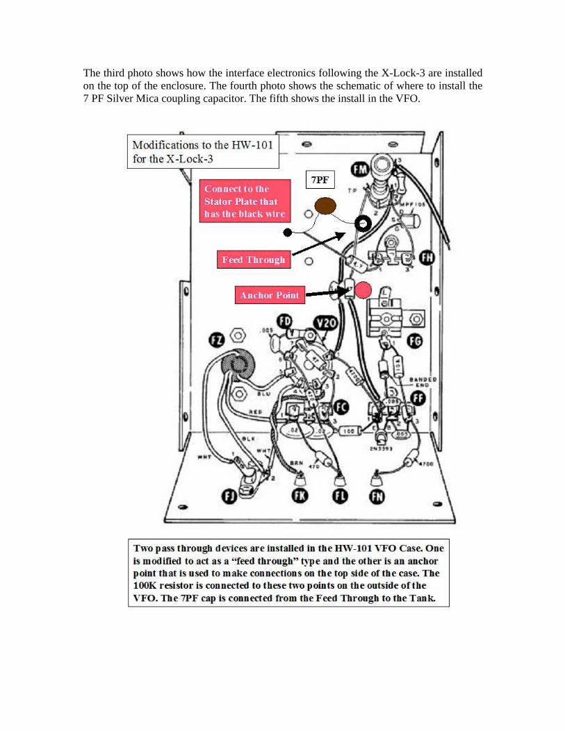
The third photo shows how the interface electronics following the X-Lock-3 are installedon the top of the enclosure. The fourth photo shows the schematic of where to install the7 PF Silver Mica coupling capacitor. The fifth shows the install in the VFO.

Note that the feed through was made from a second standoff. I simply cut the insulatingteflon about 1/16 inch from around the barrel and then cut a hole in the bottom of theteflon barrel. I was able to push the gold pin through the hole and there is a stop on theshaft to stop the shortened teflon barrel. Thus I had a connection points at either end. Youcan observe the shortened barrel and length of the gold post in the left feed through. Onthe underside of the feed through I soldered a very stiff wire as an anchor point since Iwould be testing various coupling caps and this enabled making component changes.
A note about the feed through and the anchor point in terms of installation. When drillingthe holes in the top of the chassis use a drill smaller than the Teflon barrel diameter. Thenwith a small fine round file carefully enlarge the hole while constantly testing if the teflonwill fit into the enlarge hole. Stop just at the point where it almost fits and then “press fit”the feed through and anchor point so it is a tight fit. This will anchor them so there is nomovement. This takes time to do –so don’t rush it!
A solder lug was fitted to one of the screws which anchor the variable capacitor and thisprovided a convenient connection point for grounding the anode end of the 1N4004 andthe 10 NF bypass cap. This arrangement provides for short component connection leads.This is a very stout install so there is no physical movement of the components. [Keep inmind where prior planning makes the job easier.]

Feed point fromthe X-Lock-3.
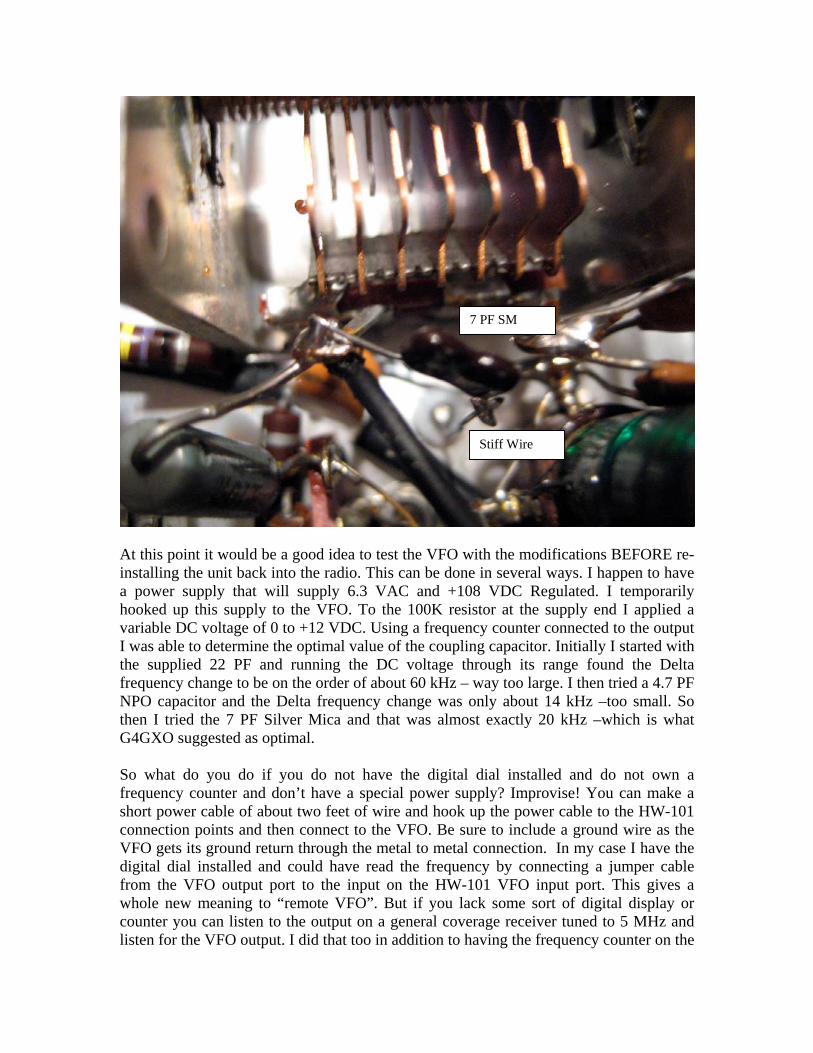
At this point it would be a good idea to test the VFO with the modifications BEFORE re-installing the unit back into the radio. This can be done in several ways. I happen to havea power supply that will supply 6.3 VAC and +108 VDC Regulated. I temporarilyhooked up this supply to the VFO. To the 100K resistor at the supply end I applied avariable DC voltage of 0 to +12 VDC. Using a frequency counter connected to the outputI was able to determine the optimal value of the coupling capacitor. Initially I started withthe supplied 22 PF and running the DC voltage through its range found the Deltafrequency change to be on the order of about 60 kHz – way too large. I then tried a 4.7 PFNPO capacitor and the Delta frequency change was only about 14 kHz –too small. Sothen I tried the 7 PF Silver Mica and that was almost exactly 20 kHz –which is whatG4GXO suggested as optimal.
So what do you do if you do not have the digital dial installed and do not own afrequency counter and don’t have a special power supply? Improvise! You can make ashort power cable of about two feet of wire and hook up the power cable to the HW-101connection points and then connect to the VFO. Be sure to include a ground wire as theVFO gets its ground return through the metal to metal connection. In my case I have thedigital dial installed and could have read the frequency by connecting a jumper cablefrom the VFO output port to the input on the HW-101 VFO input port. This gives awhole new meaning to “remote VFO”. But if you lack some sort of digital display orcounter you can listen to the output on a general coverage receiver tuned to 5 MHz andlisten for the VFO output. I did that too in addition to having the frequency counter on the
7 PF SM
Stiff Wire
output. Once you are assured that the VFO is working and the frequency spread is as itshould be disconnect the wiring and re-install the VFO in the reverse sequence. Start firstby taping down the two screws that hold the L shaped crystal filter bracket. Next installthe VFO enclosure etc.
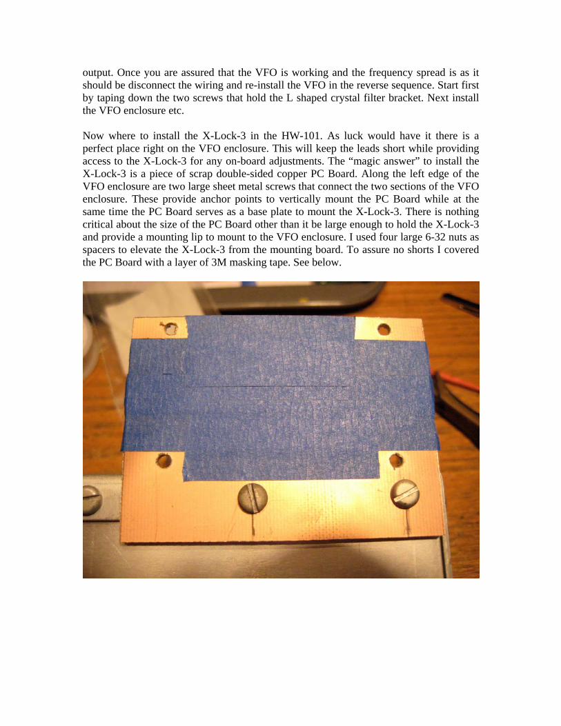
Now where to install the X-Lock-3 in the HW-101. As luck would have it there is aperfect place right on the VFO enclosure. This will keep the leads short while providingaccess to the X-Lock-3 for any on-board adjustments. The “magic answer” to install theX-Lock-3 is a piece of scrap double-sided copper PC Board. Along the left edge of theVFO enclosure are two large sheet metal screws that connect the two sections of the VFOenclosure. These provide anchor points to vertically mount the PC Board while at thesame time the PC Board serves as a base plate to mount the X-Lock-3. There is nothingcritical about the size of the PC Board other than it be large enough to hold the X-Lock-3and provide a mounting lip to mount to the VFO enclosure. I used four large 6-32 nuts asspacers to elevate the X-Lock-3 from the mounting board. To assure no shorts I coveredthe PC Board with a layer of 3M masking tape. See below.

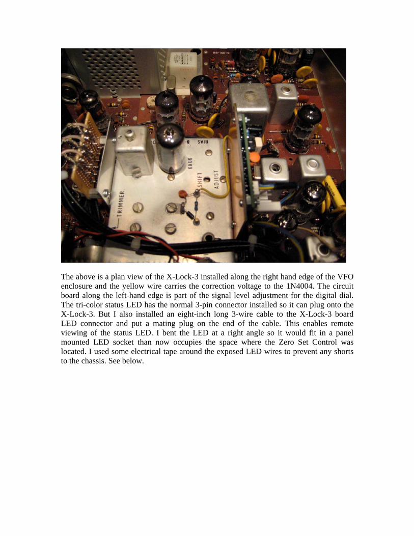
The above is a plan view of the X-Lock-3 installed along the right hand edge of the VFOenclosure and the yellow wire carries the correction voltage to the 1N4004. The circuitboard along the left-hand edge is part of the signal level adjustment for the digital dial.The tri-color status LED has the normal 3-pin connector installed so it can plug onto theX-Lock-3. But I also installed an eight-inch long 3-wire cable to the X-Lock-3 boardLED connector and put a mating plug on the end of the cable. This enables remoteviewing of the status LED. I bent the LED at a right angle so it would fit in a panelmounted LED socket than now occupies the space where the Zero Set Control waslocated. I used some electrical tape around the exposed LED wires to prevent any shortsto the chassis. See below.


The next phase is to build the DC Power Supply to power the X-Lock-3. G4GXOrecommends a supply voltage in the range of +10 VDC to no more than +16 VDC. Thereason for the + 10 VDC is that the X-Lock-3 has two on board regulators, one at + 5VDC and the other at + 8 VDC. You need a several volt differential to have the + 8 VDCregulator to work properly thus the + 10 VDC. On the other end you need a several voltdifferential to produce + 10 VDC. The source that was chosen was the 12.6 VACfilament supply that was run into a 1N4007 diode that is configured as a simple dioderectifier. Given the low current draw you would expect around 13 or so VDC comingfrom that rectifier which is more than ample to drive an LM317 Adjustable voltageregulator. By selecting two values of resistors it is possible to develop a whole array offixed output, regulated voltages. There are calculators and look up tables on the Internetthat give the values and expected outputs. I chose 220 Ohms and 1650 Ohms. With thesevalues the LM317 outputs +10.5 VDC –perfect! Below is the schematic of the powersupply to power the X-Lock-3. The LM317 has another function in that it will “clean up”the input signal, so that is a bonus. The power supply was built on a small piece of RadioShack Perforated Board and mounted on the underside of the chassis.
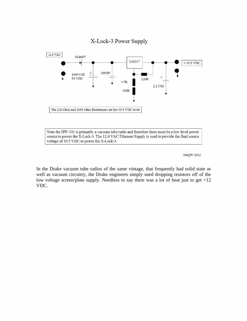
In the Drake vacuum tube radios of the same vintage, that frequently had solid state aswell as vacuum circuitry, the Drake engineers simply used dropping resistors off of thelow voltage screen/plate supply. Needless to say there was a lot of heat just to get +12VDC.

These are the two power supply boards, one for the digital dial and the other for theX-Lock-3. The one of the right is the X-Lock-3. It was difficult to find space on theunderside of the HW-101 to add circuit boards. I found one spot where I could install twoaluminum pillars approximately 3/8 inch high that were spaced the exact width of theRadio Shack Perforated Board. One of the pillars mounting holes was actually inside thePA cage. So as you can well understand – measure 40 times and cut once. In order toutilize a single set of pillars to support both power supply boards, I notched the powersupply board for the X-Lock-3 so that the board mounting holes could be utilized and yetthe board itself not interfere with already installed components. If you look carefully atthe top mounting screw you will see three diodes, which are all 1N4007. These threediodes are fed with 12.6 VAC from the filament rail to develop three separate DCvoltages. The point is that I was able to make relatively short connections from the 12.6VAC rail to the three supplies that are on the two boards. Measure 40 times and cut once.It was no accident that the boards were laid out this way! The three supplies develop 9.66VDC and 5 VDC for the Digital Dial plus 10.5 VDC for the X-Lock-3. For those skilledat making printed circuit boards this of course would make the install much easier as asmaller footprint board could be developed. Below is a birds eye view of the bottom sideof the HW-101 to give you a feel of the not too much available space to add circuitboards.

The last phase is the final integration and that is to simply connect the VFO input thatwas sampled from the lead going to HW101 circuit board. The power was connected tothe X-Lock-3 and a lead was connected from the voltage correction pin to the correctioncircuit installed on the top of the VFO enclosure. At power on the status led goes throughits start up sequence only it will blink “red” for several seconds – the buffer stagefollowing the solid state oscillator is a vacuum tube and will have no output until it iswarmed up. Then it will lock “green” indicating that it is working. Now the digital dialreading does not move!
One very nice feature of the X-Lock-3 is that operating CW. It is so cool to key the radioand see the digital dial display change to the CW offset frequency and then return to thestored frequency when you have completed the CW keying sequence. Thank you Ron forincluding this feature in the X-Lock-3!
With the Digital Dial and the X-Lock-3 this is about a $120 upgrade. To breathe new lifeinto an older vintage radio that is less expensive than buying a whole new radio! The X-Lock-3 kit costs about $55 as delivered from the UK and is well worth the cost. Thedigital dial once set on frequency does not move. The HW-101 by itself was a well -designed radio for its time. The updating of the radio with the known circuitimprovements and addition of some current technology now makes the HW-101 amodern radio.

73’sPete N6QW