implementing solar technologies at airports - nrel · pdf fileimplementing solar technologies...
TRANSCRIPT

NREL is a national laboratory of the U.S. Department of Energy Office of Energy Efficiency & Renewable Energy Operated by the Alliance for Sustainable Energy, LLC This report is available at no cost from the National Renewable Energy Laboratory (NREL) at www.nrel.gov/publications.
Contract No. DE-AC36-08GO28308
Implementing Solar Technologies at Airports A. Kandt and R. Romero
Technical Report NREL/TP-7A40-62349 July 2014
NREL is a national laboratory of the U.S. Department of Energy Office of Energy Efficiency & Renewable Energy Operated by the Alliance for Sustainable Energy, LLC This report is available at no cost from the National Renewable Energy Laboratory (NREL) at www.nrel.gov/publications.
Contract No. DE-AC36-08GO28308
National Renewable Energy Laboratory 15013 Denver West Parkway Golden, CO 80401 303-275-3000 • www.nrel.gov
Implementing Solar Technologies at Airports A. Kandt and R. Romero
Prepared under Task No. WFG4.1010
Technical Report NREL/TP-7A40-62349 July 2014
NOTICE
This report was prepared as an account of work sponsored by an agency of the United States government. Neither the United States government nor any agency thereof, nor any of their employees, makes any warranty, express or implied, or assumes any legal liability or responsibility for the accuracy, completeness, or usefulness of any information, apparatus, product, or process disclosed, or represents that its use would not infringe privately owned rights. Reference herein to any specific commercial product, process, or service by trade name, trademark, manufacturer, or otherwise does not necessarily constitute or imply its endorsement, recommendation, or favoring by the United States government or any agency thereof. The views and opinions of authors expressed herein do not necessarily state or reflect those of the United States government or any agency thereof.
This report is available at no cost from the National Renewable Energy Laboratory (NREL) at www.nrel.gov/publications.
Available electronically at http://www.osti.gov/scitech
Available for a processing fee to U.S. Department of Energy and its contractors, in paper, from:
U.S. Department of Energy Office of Scientific and Technical Information P.O. Box 62 Oak Ridge, TN 37831-0062 phone: 865.576.8401 fax: 865.576.5728 email: mailto:[email protected]
Available for sale to the public, in paper, from:
U.S. Department of Commerce National Technical Information Service 5285 Port Royal Road Springfield, VA 22161 phone: 800.553.6847 fax: 703.605.6900 email: [email protected] online ordering: http://www.ntis.gov/help/ordermethods.aspx
Cover Photos: (left to right) photo by Pat Corkery, NREL 16416, photo from SunEdison, NREL 17423, photo by Pat Corkery, NREL 16560, photo by Dennis Schroeder, NREL 17613, photo by Dean Armstrong, NREL 17436, photo by Pat Corkery, NREL 17721.
NREL prints on paper that contains recycled content.
iii
This report is available at no cost from the National Renewable Energy Laboratory (NREL) at www.nrel.gov/publications.
Acknowledgments The U.S. Department of Energy’s National Renewable Energy Laboratory (NREL) thanks the U.S. Department of Homeland Security (DHS) for supporting this work. NREL also expresses gratitude to the DHS components for proactively seeking direction and support in identifying existing guidance for appropriately siting solar systems at or near airports.
iv
This report is available at no cost from the National Renewable Energy Laboratory (NREL) at www.nrel.gov/publications.
List of Acronyms AC alternating current ATCT airport traffic control tower ALP airport layout plan CNS communication, navigation, and surveillance CSP concentrating solar power DC direct current DIA Denver International Airport DOD U.S. Department of Defense DOE U.S. Department of Energy FAA Federal Aviation Administration HQ headquarters kW kilowatt kWh kilowatt-hour MHT Manchester-Boston Regional Airport MW megawatt NREL National Renewable Energy Laboratory NWRC National Wildlife Research Center PV photovoltaics REC renewable energy certificate SGHAT Solar Glare Hazard Analysis Tool SHW solar hot water SVP solar ventilation preheat USDA U.S. Department of Agriculture USFW U.S. Fish and Wildlife Service VALE Voluntary Airport Low Emissions Wp (peak) watt

v
This report is available at no cost from the National Renewable Energy Laboratory (NREL) at www.nrel.gov/publications.
Executive Summary Federal agencies, such as the Department of Defense and Department of Homeland Security, as well as numerous private entities are actively pursuing the installation of solar technologies to help reduce fossil fuel energy use and associated emissions, meet sustainability goals, and create more robust or reliable operations. One potential approach identified for siting solar technologies is the installation of solar energy technologies at airports and airfields, which present a significant opportunity for hosting solar technologies due to large amounts of open land. In particular, solar photovoltaics (PV) have a low profile and the potential to have low to no impact on flight operations.
This report focuses largely on the Federal Aviation Administration’s (FAA’s) policies toward siting solar technologies at airports. The FAA’s policies cover fixed-axis, flat-plate solar technologies, including solar PV and solar thermal hot water systems. These policies apply to federally obligated airports. Private airports and land adjacent to airports are not covered under these policies, though the FAA encourages stakeholders of such lands who are interested in siting solar systems on those lands follow the FAA’s policies. The FAA’s policies outline how an airport sponsor can gain approval from FAA to amend an airport layout plan to add a solar system. The FAA also offers design resources to help to minimize glint and glare impacts. With proper advanced planning and siting considerations, solar technologies can successfully be installed at airports with minimal or no impacts. This paper concludes with examples of solar installations at airports and highlights a case study where successful systems were installed at the Denver International Airport in Denver, Colorado.

vi
This report is available at no cost from the National Renewable Energy Laboratory (NREL) at www.nrel.gov/publications.
Table of Contents Acknowledgments ..................................................................................................................................... iii List of Acronyms ........................................................................................................................................ iv Executive Summary .................................................................................................................................... v List of Figures ........................................................................................................................................... vii List of Tables ............................................................................................................................................. vii 1 Introduction ........................................................................................................................................... 1
1.1 Project Background ....................................................................................................................... 1 1.2 Scale of Opportunity ..................................................................................................................... 1
2 Solar Technology Overview ................................................................................................................ 2 2.1 Solar Photovoltaics ....................................................................................................................... 2
2.1.1 Photovoltaics Economics ................................................................................................. 3 3 Guidance ............................................................................................................................................... 5
3.1 Federal Aviation Administration Policies ..................................................................................... 5 3.1.1 Technical Guidance for Evaluating Selected Solar Technologies on Airports ................ 5 3.1.2 Interim Policy, Federal Aviation Administration Review of Solar Energy System
Projects on Federally Obligated Airports ......................................................................... 6 3.2 Department of Defense Memorandum ........................................................................................ 11 3.3 Siting Considerations for Airports .............................................................................................. 11
3.3.1 System Performance ....................................................................................................... 12 3.3.2 Minimizing Glare and Glint ........................................................................................... 12 3.3.3 Wildlife Impact .............................................................................................................. 13
4 Applications ........................................................................................................................................ 14 4.1 Denver International Airport Solar Photovoltaics Case Study .................................................... 14 4.2 Manchester-Boston Regional Airport Solar Photovoltaics Case Study ...................................... 16 4.3 Unique Airport Applications ....................................................................................................... 19
5 Conclusions ........................................................................................................................................ 20 Appendix .................................................................................................................................................... 21
Other Solar Technologies ..................................................................................................................... 21 Concentrating Solar Power .......................................................................................................... 21 Solar Hot Water ........................................................................................................................... 22 Solar Ventilation Preheat ............................................................................................................ 23
vii
This report is available at no cost from the National Renewable Energy Laboratory (NREL) at www.nrel.gov/publications.
List of Figures Figure 1. Geographic Information System map of U.S. solar PV resources ................................................. 3 Figure 2. Solar glare hazard analysis plot ..................................................................................................... 8 Figure 3. Input page of SGHAT.................................................................................................................... 9 Figure 4. Results tab for observation point, with glare occurrence plot ..................................................... 10 Figure 5. Solar PV at DIA ........................................................................................................................... 15 Figure 6. Location of solar PV at DIA ........................................................................................................ 16 Figure 7. Solar PV at MHT ......................................................................................................................... 18 Figure A-1. Geographic Information System map of U.S. concentrating solar resources .......................... 22
List of Tables Table 1. DIA Solar PV Installation Statistics ............................................................................................. 15
1
This report is available at no cost from the National Renewable Energy Laboratory (NREL) at www.nrel.gov/publications.
1 Introduction
1.1 Project Background Many Federal agencies, such as the Department of Defense and Department of Homeland Security, as well as numerous private entities are actively pursuing the installation of solar technologies to help reduce fossil fuel energy use and associated emissions, meet sustainability goals, and create more robust or reliable operations. One potential approach identified for siting solar technologies is the installation of solar energy technologies at airports and airfields, which present a significant opportunity for hosting solar technologies due to large amounts of open land. In particular, solar photovoltaics (PV) have a low profile and the potential to have low to no impact on flight operations.
This study outlines the technical, economic, and operational implications of siting solar technologies at airports and airfields. This document can be used to inform project managers of existing requirements and to help influence future policies as they are being revised or developed. The document most directly supports staff considering solar projects at airports. The report outlines existing guidance for implementing solar technologies at airports and airfields, details best practices for siting solar at these locations, and highlights a successful case study where solar was installed at an airport.
1.2 Scale of Opportunity A study conducted by the FAA, U.S. Department of Agriculture (USDA), and U.S. Fish and Wildlife Service (USFWS) stated that in 2010 there were approximately 15,000 public airports in the United States.1 Of those, 2,915 airports were considered significant to national air transportation and are included in the National Plan of Integrated Airport Systems. The report’s authors estimated there are approximately 3,306 square kilometers (816,930 acres) of grassland within the 2,915 significant airport properties in the contiguous United States.2 The authors contend that grasslands are representative of idle lands at airports. Assuming that 7 acres of grassland could host 1 megawatt (MW) of fixed-axis (non-tracking) photovoltaics (PV), there’s potential for 116,704 MW of PV on idle lands at airports in the United States. These calculations do not include small or military airfields, and thus, can be considered conservative.
1 “The World Factbook.” Central Intelligence Agency, 2010. Accessed Sept. 8, 2010: www.cia.gov/library/publications/the-world-factbook/geos/us.html. 2 DeVault, T.; Belant, J.; Blackwell B.; Martin, J.; Schmidt, J.; Burger Jr., L.; Patterson Jr., J. “Airports Offer Unrealized Potential for Alternative Energy Production.” Environmental Management (49), 2012; pp. 517-522. www.aphis.usda.gov/wildlife_damage/nwrc/publications/12pubs/devault123.pdf.
2
This report is available at no cost from the National Renewable Energy Laboratory (NREL) at www.nrel.gov/publications.
2 Solar Technology Overview Solar energy technologies, such as solar PV, are mature, commercially available renewable energy technologies. The focus of this paper is PV, as it has the largest potential applicability for deployment at airports. Other solar technologies are briefly outlined in the Appendix, as they also may have some deployment potential at airports.
2.1 Solar Photovoltaics Photovoltaic arrays convert sunlight to electricity. The systems require very little maintenance, make no noise, and operate without moving parts and without producing air pollution or greenhouse gases. Arrays can be mounted on buildings and structures (such as parking garages) or ground-mounted on supporting poles or racks. The arrays produce direct current (DC), which can be conditioned into grid-quality alternating current (AC) electricity or used to charge batteries. A typical PV cell converts approximately 14% of the solar energy striking its surface into usable electricity.3
The amount of electricity a system produces depends on the system type, orientation, and the available solar resource. The solar resource is the amount of the sun’s energy reaching the earth’s surface, which varies across the United States. A higher solar resource means more of the sun’s energy is reaching the surface, which is optimal for PV system performance. The solar resource map in Figure 1 details the available solar resource throughout the country in kilowatt-hours per meter squared per day. Resources are highest in the southwest, and fairly high throughout the western states, Texas, and Florida.
3 “Photovoltaics Resources and Technologies.” U.S. Department of Energy, Office of Renewable Energy & Energy Efficiency, 2013. http://energy.gov/eere/femp/articles/photovoltaic-resources-and-technologies.

3
This report is available at no cost from the National Renewable Energy Laboratory (NREL) at www.nrel.gov/publications.
Figure 1. Geographic Information System map of U.S. solar PV resources
Photovoltaics Economics 2.1.1The cost of PV-generated electricity has dropped 15- to 20-fold in the last 40 years. Grid-connected PV systems sell for between 20¢ per kilowatt-hour (kWh) and 32¢/kWh in 2011, or about $5 per (peak) watt (Wp) to $8/Wp, including support structures and power conditioning equipment. Peak-watt is the power rating that a PV system measures under standard test conditions, and under which a panel could be expected to deliver its peak output. An NREL study of 7,074 PV systems installed in 2007 reported a range of total capital costs averaging $8.32/Wp for small systems less than 10 kilowatts (kW) and $6.87/Wp for large systems greater than 100 kW; costs have dropped further since then. Costs reported for PV projects are decreasing rapidly, so a local solar installer may be the best source of current cost information. Operation and maintenance costs are reported at $0.008/kWh produced, or at 0.17% of capital cost without tracking and 0.35% with tracking.4 The systems are very reliable and last 20 years or longer.5
Siting PV systems at airports costs marginally more than systems sited in other locations. Additional costs could be incurred for project planning and coordination with FAA and related glare/glint studies.
A variety of financing mechanisms exist to help facilitate the installation of PV systems. Third-party financing, in which an entity finances, owns, and operates the system, is a mechanism for installing a PV system for little or no capital and is most often utilized for commercial- or utility-scale systems. These mechanisms include power purchase agreements, energy savings performance contracts, and utility energy services contracts.6 In addition, the FAA operates the 4 Mortensen, J. Factors Associated with Photovoltaic System Costs. NREL/TP-620-29649. Golden, CO: National Renewable Energy Laboratory, 2001. 5 Guey-Lee, L. “Forces Behind Wind Power.” Renewable Energy 2000, (73), February 2001. 6 “Project Funding.” U.S. Department of Energy, Office of Energy Efficiency & Renewable Energy, undated. Accessed June 2011: http://energy.gov/eere/femp/project-funding.
4
This report is available at no cost from the National Renewable Energy Laboratory (NREL) at www.nrel.gov/publications.
Voluntary Airport Low Emissions (VALE) program, which helps airport sponsors meet their state-related air quality responsibilities under the Clean Air Act.7 Through VALE, airport sponsors can be eligible for funds to help support the procurement and installation of PV systems. The Manchester-Boston Regional Airport (MHT) project, in the city of Manchester, New Hampshire, benefited from VALE funds that covered 95% of PV system costs. This system is detailed in Section 4.2 of this report.8, 9
7 “Voluntary Airport Low Emissions Program (VALE): Airports.” Federal Aviation Administration, 2014. www.faa.gov/airports/environmental/vale/. 8 Hayward, M. “Airport controllers complain of solar panels' glare.” New Hampshire Union Leader, Aug. 30, 2012. www.unionleader.com/article/20120830/NEWS02/708309966. 9 “Solar Project.” Manchester-Boston Regional Airport newsletter, Holiday 2012. www.flymanchester.com/newsletters/holiday-2012/solar-project.

5
This report is available at no cost from the National Renewable Energy Laboratory (NREL) at www.nrel.gov/publications.
3 Guidance The most broadly known and utilized guidance is issued by FAA and is summarized below. The DOD recently issued a memorandum on glint and glare issues on or near DOD aviation operations; that memo is also summarized.
3.1 Federal Aviation Administration Policies The FAA is the national aviation authority of the United States. It has authority to regulate and oversee all aspects of American civil aviation.10 There are nine FAA regions and 21 FAA airport district offices that manage the FAA’s day-to-day operations with the nation’s airports. These operations include airport safety and standards, grant management, and compliance. The FAA Office of Airports in Washington D.C. (FAA Headquarters) develops national policies, standards, regulations, and guidance for the national system of airports and oversees federal funding, compliance, and airport environmental reviews. Generally, solar projects are reviewed at the regional level, with FAA Headquarters becoming involved only if a project requires additional resources or presents a complex problem.11
The FAA has an interest in solar energy for a multitude of reasons. The agency supports modernization and improved efficiency, and as such, supports appropriate solar projects. In some instances, the FAA is a PV operator, generally at remote or off-grid facilities. It works to ensure solar projects are sited properly and do not cause safety problems for aviation or otherwise interfere with aeronautical and airport activities. Specifically, the FAA wants to ensure solar systems do not create glint or glare conditions (glint is a momentary flash of bright light, and glare is a continuous source of bright light). The FAA has determined that glint and glare from typical ground-mounted solar energy systems could result in an ocular impact to pilots and/or air traffic control facilities and compromise the safety of the air transportation system. While the FAA supports solar energy systems on airports, the FAA seeks to ensure safety by eliminating the potential for ocular impact to pilots and/or air traffic control facilities due to glare from such projects.12
Technical Guidance for Evaluating Selected Solar Technologies on Airports 3.1.1In November 2010, the FAA released a document titled Technical Guidance for Evaluating Selected Solar Technologies on Airports.13 The FAA created this document to provide a readily usable reference for FAA technical staff who review proposed airport solar projects and for airport sponsors that may be considering a solar installation. It addresses a wide range of topics,
10 “Safety: The Foundation of Everything We Do.” Federal Aviation Administration, 2014. www.faa.gov/about/safety_efficiency/. 11 Technical Guidance for Evaluating Selected Solar Technologies on Airports. Washington, D.C.: Federal Aviation Administration, November 2010. www.faa.gov/airports/environmental/policy_guidance/media/airport_solar_guide_print.pdf. 12 “Interim Policy, FAA Review of Solar Energy System Projects on Federally Obligated Airports.” Federal Register, Oct. 23, 2013. www.federalregister.gov/articles/2013/10/23/2013-24729/interim-policy-faa-review-of-solar-energy-system-projects-on-federally-obligated-airports. 13 Technical Guidance for Evaluating Selected Solar Technologies on Airports. Washington, D.C.: Federal Aviation Administration, November 2010. www.faa.gov/airports/environmental/policy_guidance/media/airport_solar_guide_print.pdf.

6
This report is available at no cost from the National Renewable Energy Laboratory (NREL) at www.nrel.gov/publications.
including solar technology, electric grid infrastructure, FAA safety regulations, financing alternatives, incentives, and case studies.14
One of the case studies highlights an unsuccessful installation and details the associated implications. More information on this case study, including potential resolution to the installation issues, is provided in Section 4.2 of this report. This is currently the only existing publically available and federally issued guidance for installing solar technologies at airports and is a good reference document for all relevant stakeholders. Perhaps most useful for those parties interested in siting solar systems at airports, the report includes a checklist of FAA procedures to ensure the systems are safe and pose no risk to pilots, air traffic controllers, or airport operations.
There is a note on the initial page of the report stating:
As of October 23, 2013, the FAA is reviewing multiple sections of the Technical Guidance for Evaluating Selected Solar Technologies on Airports based on new information and field experience, particularly with respect to compatibility and glare. All users of this guidance are hereby notified that significant content in this document may be subject to change, and the FAA cautions users against relying solely on this document at this time. Users should refer instead to the interim policy (http://federalregister.gov/a/2013-24729).
The interim policy is detailed below. This update to the technical guidance includes the standards for measuring glint and glare outlined in the interim policy. It also provides enhanced criteria to ensure the proper siting of a solar energy installation to eliminate the potential for harmful glare to pilots or air traffic control facilities.15 A notice on the website states that, “The interim policy replaces the guidance for reflectivity found in Section 3.1.2 of the Technical Guidance for Evaluating Selected Solar Technologies on Airports.”16
Interim Policy, Federal Aviation Administration Review of Solar Energy 3.1.2System Projects on Federally Obligated Airports
On Oct. 23, 2013, a notice was posted by the FAA on the Federal Register, titled Interim Policy, FAA Review of Solar Energy System Projects on Federally Obligated Airports. The notice states that in 2012, the FAA partnered with the U.S. Department of Energy (DOE) “to establish a standard for measuring glint and glare, and clear thresholds for when glint and glare would impact aviation safety. The standards that this working group developed are set forth in this notice.”17 The notice also reads:
14 Technical Guidance for Evaluating Selected Solar Technologies on Airports. Washington, D.C.: Federal Aviation Administration, November 2010. www.faa.gov/airports/environmental/policy_guidance/media/airport_solar_guide_print.pdf. 15 “Interim Policy, FAA Review of Solar Energy System Projects on Federally Obligated Airports.” Federal Register, Oct. 23, 2013. www.federalregister.gov/articles/2013/10/23/2013-24729/interim-policy-faa-review-of-solar-energy-system-projects-on-federally-obligated-airports. 16 www.faa.gov/airports/environmental/ 17 “Interim Policy, FAA Review of Solar Energy System Projects on Federally Obligated Airports.” Federal Register, Oct. 23, 2013. www.federalregister.gov/articles/2013/10/23/2013-24729/interim-policy-faa-review-of-solar-energy-system-projects-on-federally-obligated-airports.

7
This report is available at no cost from the National Renewable Energy Laboratory (NREL) at www.nrel.gov/publications.
The FAA is adopting an interim policy because it is in the public interest to enhance safety by clarifying and adding standards for measuring ocular impact of proposed solar energy systems. FAA will consider comments and make appropriate modifications before issuing a final policy in a future Federal Register Notice. The policy applies to any proposed solar energy system that has not received unconditional airport layout plan (ALP) approval or a “no objection” from the FAA on a filed 7460-1, Notice of Proposed Construction or Alteration. The FAA expects to continue to update these policies and procedures as part of an iterative process as new information and technologies become available.18
It should be noted that solar energy systems located on an airport that is not federally obligated or located outside the property of a federally obligated airport are not subject to this policy. Proponents of solar energy systems located off airport property or on nonfederally obligated airports are strongly encouraged to consider the requirements of this policy when siting such systems. Considerations outlined in the notice include:
• A sponsor of a federally obligated airport must notify the FAA of its intent to construct any solar installation, including the intent to permit airport tenants, such as federal agencies, to build such installations.19
o A sponsor of a federally obligated airport must request FAA review and approval to depict proposed solar installations that will either be ground-based installations or that are not ground-based but substantially change the footprint of a colocated building or structure (i.e., a roof-mounted system that increases the footprint of an existing building or structure) on its ALP, before construction begins.
o Airport sponsors and project proponents must comply with the policies and procedures outlined in the Interim Policy in order to demonstrate to the FAA that a proposed solar energy system will not result in an ocular impact that compromises the safety of the air transportation system.20
o The airport sponsor, in siting a proposed solar energy system, is responsible for limiting the potential for inference with communication, navigation, and surveillance (CNS) facilities by ensuring that solar energy systems remain clear of the critical areas surrounding CNS facilities.
Standards for Measuring Ocular Impact The notice states the FAA prescribes the solar glare hazard analysis plot as the standard for measuring the potential ocular impact of any proposed solar energy system on a federally
18 “Interim Policy, FAA Review of Solar Energy System Projects on Federally Obligated Airports.” Federal Register, Oct. 23, 2013. www.federalregister.gov/articles/2013/10/23/2013-24729/interim-policy-faa-review-of-solar-energy-system-projects-on-federally-obligated-airports. 19 The sponsor must notify FAA by filing FAA Form 7460-1, “Notice of Proposed Construction or Alteration,” under 14 CFR Part 77 for a nonrulemaking case. 20 This process enables the FAA to approve amendment of the ALP to depict certain solar energy projects or issue a “no objection” finding to a filed 7460-1 form.

8
This report is available at no cost from the National Renewable Energy Laboratory (NREL) at www.nrel.gov/publications.
obligated airport (see Figure 2). The airport sponsor must reference this plot and utilize the associated Solar Glare Hazard Analysis Tool (SGHAT)21 to demonstrate the potential for glare and glint resulting from a proposed solar project. Non-federally obligated airports or solar systems adjacent to an airport are encouraged to utilize this tool as well, though are not required to. The FAA will consider the use of alternative tools or methods on a case-by-case basis. 22
Figure 2. Solar glare hazard analysis plot
Source: Federal Register
In order for an airport sponsor to obtain FAA approval to revise an airport layout plan to depict a solar installation and/or a “no objection” to a Notice of Proposed Construction Form 7460-1, the sponsor is required to demonstrate the proposed solar energy system meets the following standards:23
• No potential for glint or glare in the existing or planned airport traffic control tower (ATCT) cab
• No potential for glare or “low potential for after-image” along the final approach path for any existing landing threshold or future landing thresholds (including any planned
21 The Solar Glare Hazard Analysis Tool is available at: https://share.sandia.gov/phlux. 22 “Interim Policy, FAA Review of Solar Energy System Projects on Federally Obligated Airports.” Federal Register, Oct. 23, 2013. www.federalregister.gov/articles/2013/10/23/2013-24729/interim-policy-faa-review-of-solar-energy-system-projects-on-federally-obligated-airports. 23 The standards are taken verbatim from the: “Interim Policy, FAA Review of Solar Energy System Projects on Federally Obligated Airports.” Federal Register, Oct. 23, 2013. www.federalregister.gov/articles/2013/10/23/2013-24729/interim-policy-faa-review-of-solar-energy-system-projects-on-federally-obligated-airports.
9
This report is available at no cost from the National Renewable Energy Laboratory (NREL) at www.nrel.gov/publications.
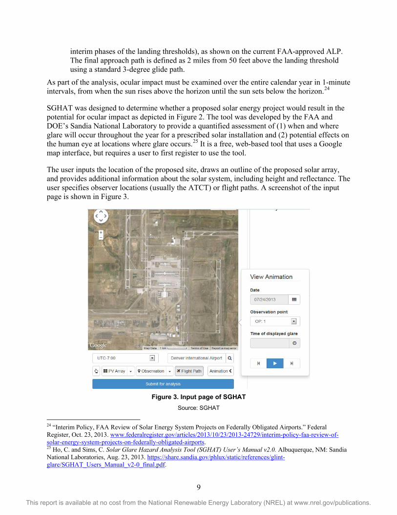
interim phases of the landing thresholds), as shown on the current FAA-approved ALP. The final approach path is defined as 2 miles from 50 feet above the landing threshold using a standard 3-degree glide path.
As part of the analysis, ocular impact must be examined over the entire calendar year in 1-minute intervals, from when the sun rises above the horizon until the sun sets below the horizon.24
SGHAT was designed to determine whether a proposed solar energy project would result in the potential for ocular impact as depicted in Figure 2. The tool was developed by the FAA and DOE’s Sandia National Laboratory to provide a quantified assessment of (1) when and where glare will occur throughout the year for a prescribed solar installation and (2) potential effects on the human eye at locations where glare occurs.25 It is a free, web-based tool that uses a Google map interface, but requires a user to first register to use the tool.
The user inputs the location of the proposed site, draws an outline of the proposed solar array, and provides additional information about the solar system, including height and reflectance. The user specifies observer locations (usually the ATCT) or flight paths. A screenshot of the input page is shown in Figure 3.
Figure 3. Input page of SGHAT
Source: SGHAT 24 “Interim Policy, FAA Review of Solar Energy System Projects on Federally Obligated Airports.” Federal Register, Oct. 23, 2013. www.federalregister.gov/articles/2013/10/23/2013-24729/interim-policy-faa-review-of-solar-energy-system-projects-on-federally-obligated-airports. 25 Ho, C. and Sims, C. Solar Glare Hazard Analysis Tool (SGHAT) User’s Manual v2.0. Albuquerque, NM: Sandia National Laboratories, Aug. 23, 2013. https://share.sandia.gov/phlux/static/references/glint-glare/SGHAT_Users_Manual_v2-0_final.pdf.
10
This report is available at no cost from the National Renewable Energy Laboratory (NREL) at www.nrel.gov/publications.
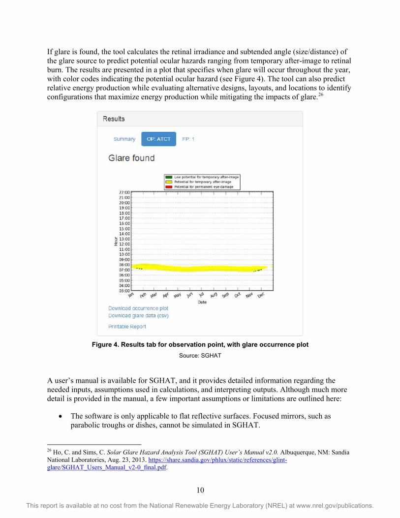
If glare is found, the tool calculates the retinal irradiance and subtended angle (size/distance) of the glare source to predict potential ocular hazards ranging from temporary after-image to retinal burn. The results are presented in a plot that specifies when glare will occur throughout the year, with color codes indicating the potential ocular hazard (see Figure 4). The tool can also predict relative energy production while evaluating alternative designs, layouts, and locations to identify configurations that maximize energy production while mitigating the impacts of glare.26
Figure 4. Results tab for observation point, with glare occurrence plot
Source: SGHAT
A user’s manual is available for SGHAT, and it provides detailed information regarding the needed inputs, assumptions used in calculations, and interpreting outputs. Although much more detail is provided in the manual, a few important assumptions or limitations are outlined here:
• The software is only applicable to flat reflective surfaces. Focused mirrors, such as parabolic troughs or dishes, cannot be simulated in SGHAT.
26 Ho, C. and Sims, C. Solar Glare Hazard Analysis Tool (SGHAT) User’s Manual v2.0. Albuquerque, NM: Sandia National Laboratories, Aug. 23, 2013. https://share.sandia.gov/phlux/static/references/glint-glare/SGHAT_Users_Manual_v2-0_final.pdf.

11
This report is available at no cost from the National Renewable Energy Laboratory (NREL) at www.nrel.gov/publications.
• SGHAT only simulates fixed systems; it does not currently apply to tracking systems.
• The software assumes the PV array is aligned with a plane defined by the total heights of the coordinates outlined in the Google map.
• SGHAT does not consider manmade or natural obstacles between the observation points and the prescribed solar installation that may obstruct observed glare, such as trees, hills, buildings, etc.
• The software currently uses a constant reflectance for the solar modules; this value is prescribed by the user. In actuality, the reflectance increases with increasing incidence angle.27
The manual also provides a case-study example of the Manchester-Boston Regional Airport, which is summarized in Section 4.2 of this paper. The case study provides an overview of a SGHAT analysis for the airport, as well as real-world examples from an installed PV system that caused glare at the air traffic control tower. The panels have since been temporarily covered to resolve the glare issue.
3.2 Department of Defense Memorandum In June of 2014 the Office of the Under Secretary of Defense issued a memorandum for the Assistant Secretary of the Army, the Assistant Secretary of the Navy, and the Acting Assistant Secretary of the Air Force with the subject ‘Glint/Glare Issues on or near DOD Aviation Operations’.28 The memo outlines the FAA’s conclusion that glint and glare from some solar systems could result in ocular impact to pilots and/or air traffic controllers. It references the FAA interim procedures and states that, “FAA’s interim guidance should only be used as a guide for consideration.”29 The memo does encourage mission compatibility evaluations to include the potential impact of glint and glare from non-residential PV and glass-enclosed solar-hot water systems. It outlines in which instances the use of the SGHAT tool is required or recommended.
3.3 Siting Considerations for Airports In addition to careful planning and assessment to ensure glare and glint are minimized or alleviated, as summarized in the FAA guidance highlighted above, other considerations need to be taken into account when siting solar systems at or near airports. In addition to those outlined here, systems should be placed an appropriate distance from the runway and should adhere to appropriate safety and fire measures.
27 Ho, C. and Sims, C. Solar Glare Hazard Analysis Tool (SGHAT) User’s Manual v2.0. Albuquerque, NM: Sandia National Laboratories, Aug. 23, 2013. https://share.sandia.gov/phlux/static/references/glint-glare/SGHAT_Users_Manual_v2-0_final.pdf. 28 http://www.acq.osd.mil/dodsc/library/Procedures_Memo_4_Glint%20Glare%20Issues%20on%20or%20near%20DoD%20Aviation%20Operations.pdf 29 http://www.acq.osd.mil/dodsc/library/Procedures_Memo_4_Glint%20Glare%20Issues%20on%20or%20near%20DoD%20Aviation%20Operations.pdf
12
This report is available at no cost from the National Renewable Energy Laboratory (NREL) at www.nrel.gov/publications.
System Performance 3.3.1An ideal solar installation would be situated in an unshaded, south-facing location with an optimum tilt angle (generally tilt equal to latitude; see third bullet below for more information). Not all sites are suitable for solar technologies. There are a few rules of thumb that are helpful in determining when solar technologies are appropriate for a site.
• It is important to identify an unshaded area for solar PV installation, particularly between the peak sun hours of 9 a.m.–3 p.m. Shade will reduce the output of a solar panel. Shade can be caused by trees, nearby buildings, and roof equipment or features (such as chimneys).
• It is best to orient fixed-mount panels due south in the northern hemisphere. Siting panels so they face east or west of due south will decrease energy production. However, that effect varies by location and could be minimal.
• In the area of Boulder, Colorado, for example, the losses due to orientation are about 4% for a panel facing 45° east of south and about 10% for one facing 45° west of south (due to the mountains to the west).30 While an orientation east or west of south is not ideal because of the resulting reduction in energy production, it may be necessary due to land availability constraints or to minimize or alleviate glint or glare issues.
• For locations in latitudes less than 20º, the optimal tilt angle for achieving the highest performance from a fixed-mount PV panel is equal to the latitude of a location. At higher latitudes, the correlation is not valid. A previous study analyzed the annual solar resource data for different latitudes.31 At a location of 40° north latitude, an optimal tilt varies from 30° to 35° to maximize the annual energy production. Fixed-mount solar panels can be flush- or tilt-mounted on roofs, pole mounted on the ground, or can be integrated into building materials, such as roofs, windows, and awnings. However, a tilt angle equal to latitude is not always feasible because of factors such as roof pitch, wind or snow loading considerations, or a need to minimize or alleviate glint and glare. It is possible to install panels at a different angle. The impact of a nonideal tilt angle varies by location and could be minimal. The energy production of PV systems at various orientation and tilt angles can be calculated by tools such as PVWatts.32
Minimizing Glare and Glint 3.3.2Aside from the strategies previously discussed, there are physical methods to potentially reduce reflection from panels and the associated glare and glint. These include the application of antireflective coatings33 and/or texturing34 to the panels. Neither has discernable effects on system performance but could help minimize reflection.
30 Analysis in PVWatts makes the following assumptions: location = Boulder, CO; tilt = latitude (40°); DC to AC derate factor = 0.77. Analysis was performed in: Kandt, A. et al. Implementing Solar PV Projects on Historic Buildings and in Historic Districts. NREL/TP-7A40-51297. Golden, CO: National Renewable Energy Laboratory, 2011. www.nrel.gov/docs/fy11osti/51297.pdf. 31 Christensen, C. and Barker, G. “Effects of Tilt and Azimuth on Annual Incident Solar Radiation for United States Locations.” Presented at 2001 Solar Energy Forum, Washington, D.C., 2001. 32 For more information, see: www.nrel.gov/rredc/pvwatts/. 33 “Anti-Reflection Coatings.” PVEducation.org, undated. http://pveducation.org/pvcdrom/design/anti-reflection-coatings.
13
This report is available at no cost from the National Renewable Energy Laboratory (NREL) at www.nrel.gov/publications.
Wildlife Impact 3.3.3Very little information is available quantifying the potential impact of solar systems on wildlife, or of wildlife on solar system installations, at airports. The previously referenced study conducted by the FAA, USDA, and USFWS states “airports offer one of the few land uses where reductions in wildlife, abundance, and habitat quality are necessary and socially acceptable, due to risk of wildlife collisions with aircraft.”35 However, when siting solar systems at airports, it is important to mitigate against creating wildlife attractants, such as perches or shade. A study by the USDA National Wildlife Research Center (NWRC) aimed to evaluate the hazard level posed by PV facilities to aircraft, compare bird and mammal use of the two land cover types (PV or open land), and provide findings and guidance to the FAA.36 Note that existing FAA guidance does not yet touch on wildlife impact or mitigation strategies.
The NWRC study compared open land with PV-covered land at airports in five locations across the country. The results indicated most observations at PV arrays were of perched birds. Birds do not present risk to aircraft when they are perched, either on or under panels. However, the study highlighted it is unclear if the PV arrays are drawing birds from outside the airport or if the observations were simply local birds that would be present regardless of the presence of PV. It concluded there is very little information available on the effects of solar energy development on wildlife, but such development is generally assumed to be negative due to habitat destruction and modification. This is in contrast to the FAA, USDA, and USFWS study, which indicated solar system development is compatible with airports due to the need to reduce wildlife abundance and habitat quality. The USDA NWRC study went on to say, though, that the observed low use of PV arrays by birds for perching or sheltering should facilitate solar development at airports, especially in regions where solar development is most promising. Furthermore, the study said “establishment of PV arrays could play a major role in efforts to design and operate “greener” airports.”37
Strategies can be taken to minimize the potential for birds being drawn to the solar system for perching or sheltering. These could include the use of spikes or other such systems on top of each panel to limit the ability of birds to perch, and potential closures or barriers behind panels to decrease the ability of birds or wildlife to shelter there.
34 “Surface Texturing.” PVEducation.org, undated. http://pveducation.org/pvcdrom/design/surface-texturing. 35 DeVault, T.; Belant, J.; Blackwell B.; Martin, J.; Schmidt, J.;Burger Jr., L.; Patterson Jr., J. “Airports Offer Unrealized Potential for Alternative Energy Production.” Environmental Management (49), 2012; pp. 517-522. www.aphis.usda.gov/wildlife_damage/nwrc/publications/12pubs/devault123.pdf. 36 DeVault, T. et al. “Wildlife Use of Solar Facilities On and Near Airports.” National Wildlife Research Center, undated. www.aaae.org/?e=showFile&l=HZMIYX. 37 DeVault, T. et al. “Wildlife Use of Solar Facilities On and Near Airports.” National Wildlife Research Center, undated. www.aaae.org/?e=showFile&l=HZMIYX.
14
This report is available at no cost from the National Renewable Energy Laboratory (NREL) at www.nrel.gov/publications.
4 Applications While airport lands are a relatively new application of solar PV, there are dozens of installations worldwide where the technology has been implemented successfully. Here is a sampling of some installed PV systems:
• Indianapolis International Airport in Indianapolis, Indiana:38 Operating as of 2013, the 12.5-MW system sits at the main airport exit.
• Fresno Yosemite Airport in Fresno, California:39 The 2-MW system was constructed in 2008, and energy production meets approximately 60% of the airports energy demand.
• Gatwick Airport in London, England:40 The 50-kW system was installed in 2012 just 150 meters from the main runway of the airport. The installation company spent about six months negotiating the siting with the United Kingdom National Air Traffic Service and the Civil Aviation Authority to ensure the solar panels were not disruptive to the airport.
• Birmingham Airport in Birmingham, England:41 Installed in 2011, the 50-kW system was installed on the roof of the terminal.
• Athens International in Athens, Greece:42 In October 2012, the Athens airport completed installation of an 8-MW system on the airport site. To ensure safe operation, a pilot PV unit was installed at the airport’s train station in 2004 to provide data for the newest installation.
• Ancona Falconara Airport in Falconara Marittima, Italy:43 The buildings surrounding the airport control tower have 45 kW of solar PV installed. Prior to the project, an analytic study was completed that looked at the sun and landing aircraft positions to ensure comfort of pilots and staff in the control tower.
4.1 Denver International Airport Solar Photovoltaics Case Study Denver International Airport (DIA), located in Denver, Colorado, has installed approximately 8 MW of solar PV on its property. In 2012, DIA was the 11th busiest airport in the world as designated by passenger traffic, so the airport sees significant air traffic as well. The solar PV installed on the airport land meets approximately 6% of the annual electricity consumption of the airport overall.
38 “The Solar Farm.” Telamon, Johnson Melloh Solutions and Brandrenew, 2013. http://indsolarfarm.com/the-solar-farm/. 39 Mick, J. “Fresno-Yosemite International Leads Green Airport Movement.” Daily Tech, July 21, 2008. www.dailytech.com/FresnoYosemite+International+Leads+Green+Airport+Movement/article12417.htm. 40 “Gatwick solar system hailed a runway success.” BusinessGreen, undated. www.businessgreen.com/bg/news/2156392/gatwick-solar-cleared. 41 “Birmingham Airport Invests in Solar Power.” Birmingham Airport, Feb. 6, 2012. www.birminghamairport.co.uk/meta/news/2012/02/solarpanels-news-article.aspx. 42 “Athens International begins operation of the world’s largest airport photovoltaic installation.” GreenAir Online, Oct. 12, 2012. www.greenaironline.com/news.php?viewStory=1350. 43 “Falconara Airport Photovoltaic System.” Convert Italia, 2013. http://trj.convertitalia.com/en/su-copertura/impianto-fotovoltaico-aeroporto-di-falconara/.

15
This report is available at no cost from the National Renewable Energy Laboratory (NREL) at www.nrel.gov/publications.
Figure 5. Solar PV at DIA
Source: Denver International Airport
The airport installed the solar PV in three phases, as shown in Table 1.
Table 1. DIA Solar PV Installation Characteristics
The project was completed via private-public partnerships, which were achieved through ground lease and power purchase agreements. Additionally, the interconnection agreements were put in place with the local utility provider. The solar PV system owner, which varies for each system, receives federal tax benefits, renewable energy certificate payments and solar rewards rebates from the local utility provider, and sells power to DIA.
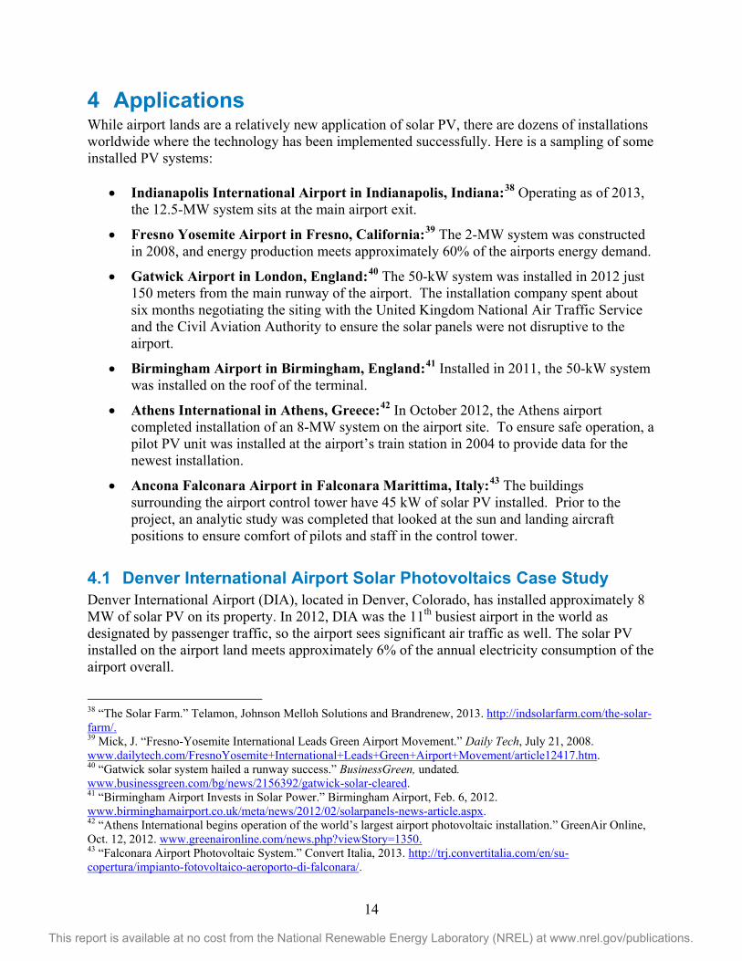
DIA has learned what it takes to install solar PV on their site. Woods Allee, director of Technical Programs in the Planning and Development Office at DIA, said that prior to design and construction of the first solar PV system, panels were brought to the site and viewed from the air traffic control tower. The solar panels, as shown in Figure 6, were viewed from several positions and orientations to ensure the panels would not affect the view from the tower. His team looked for complimentary angles to the sun and pilots’ eyes during approach and departure.
Mr. Allee said there was little to no impact to pilots or air traffic control during construction of the three DIA projects. Today, the tracking feature of DIA I ensures there are never glare or glint situations from the PV system, which is generated when there are complimentary angles between the line of site and the PV system. DIA I is the system closest to designated runway spaces.
DIA I DIA II DIA III
Capacity 2 MW DC 1.6 MW DC 4.3 MW DC
Annual Production 3.5 M kWh 2.4 M kWh 6.9 M kWh
System Flat single axis tracking 25 degree fixed tilt 25 degree fixed tilt
Total Panels 9,254 panels 7,250 Panels 18,980 panels
16
This report is available at no cost from the National Renewable Energy Laboratory (NREL) at www.nrel.gov/publications.
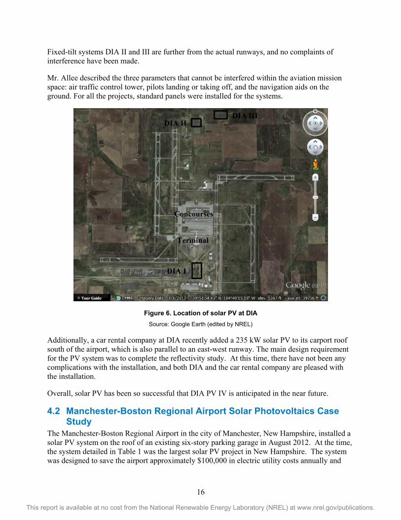
Fixed-tilt systems DIA II and III are further from the actual runways, and no complaints of interference have been made.
Mr. Allee described the three parameters that cannot be interfered within the aviation mission space: air traffic control tower, pilots landing or taking off, and the navigation aids on the ground. For all the projects, standard panels were installed for the systems.
Figure 6. Location of solar PV at DIA Source: Google Earth (edited by NREL)
Additionally, a car rental company at DIA recently added a 235 kW solar PV to its carport roof south of the airport, which is also parallel to an east-west runway. The main design requirement for the PV system was to complete the reflectivity study. At this time, there have not been any complications with the installation, and both DIA and the car rental company are pleased with the installation.
Overall, solar PV has been so successful that DIA PV IV is anticipated in the near future.
4.2 Manchester-Boston Regional Airport Solar Photovoltaics Case Study
The Manchester-Boston Regional Airport in the city of Manchester, New Hampshire, installed a solar PV system on the roof of an existing six-story parking garage in August 2012. At the time, the system detailed in Table 1 was the largest solar PV project in New Hampshire. The system was designed to save the airport approximately $100,000 in electric utility costs annually and
DIA II DIA III
DIA I
Concourses
Terminal

17
This report is available at no cost from the National Renewable Energy Laboratory (NREL) at www.nrel.gov/publications.
more than $2,000,000 over the 25-year life of the project.44 The $3.5 million project was funded under the FAA’s VALE program, which covered 95% of the costs.45,46
Table 2. Manchester-Boston Regional Airport Solar PV Installation Characteristics
MHT
Capacity 530 kW DC
Annual Production 650,000 kWh
System 20 degree fixed tilt
Total Panels 2,210 panels Source: MHT (www.flymanchester.com/newsletters/holiday-2012/solar-project)
Within the first month of installation, air traffic controllers started complaining about glare from the solar PV system, as seen in Figure 7. The glare occurred for approximately 45 minutes each morning, as seen from the tower, which was located just west of the parking garage.47 Neither aircraft pilots nor any airlines commented on glare issues. While the airport, contractor, FAA, and others sought a solution, approximately 25% of the system was covered with tarps.
44 “Solar Project.” Manchester-Boston Regional Airport newsletter, Holiday 2012. www.flymanchester.com/newsletters/holiday-2012/solar-project. 45 Hayward, M. “Airport controllers complain of solar panels' glare.” New Hampshire Union Leader, Aug. 30, 2012. www.unionleader.com/article/20120830/NEWS02/708309966. 46 “Solar Project.” Manchester-Boston Regional Airport newsletter, Holiday 2012. www.flymanchester.com/newsletters/holiday-2012/solar-project. 47 Hayward, M. “Airport controllers complain of solar panels' glare.” New Hampshire Union Leader, Aug. 30, 2012. www.unionleader.com/article/20120830/NEWS02/708309966.

18
This report is available at no cost from the National Renewable Energy Laboratory (NREL) at www.nrel.gov/publications.
Figure 7. Solar PV at MHT
Source: Sandia National Laboratory Using the SGHAT tool, a study was conducted in 2012 by Clifford K. Ho, Cianan A. Sims, Julius E. Yellowhair from Sandia National Laboratories to investigate possible solutions, and the results were published in the Solar Glare Hazard Analysis Tool (SGHAT) User's Manual v. 2.0.48 The study recommended a less reflective PV panel would create a perceptible glare decrease. The report also recommended the panels be rotated 90° to the east, which would point away from the air traffic control tower. Additional possible solutions investigated for the south-facing problem panels included:
• Moving panels • Altering the tilt • Adding blinds to the tower.
Based on recommendations from Sandia National Laboratories and a separate study by the Massachusetts Institute of Technology and the Volpe Center, the array is currently being reconstructed at 90° rotation from the current position, facing the east, to eliminate the glare problems. The rotation solution was verified with the SGHAT tool. Completion of the solar PV array facing east is expected in summer 2014 with an estimated decrease in annual output by 10% for the new orientation.
Richard Fixler, the assistant director of Engineering and Planning at MHT, says since the original glare study was completed at the airport, tools for the solar glare analysis have improved and now provide results that are more accurate today. He also points to lessons learned from other solar PV installations at airports as experience for the whole industry.
48 Ho, C. and Sims, C. Solar Glare Hazard Analysis Tool (SGHAT) User’s Manual v2.0. Albuquerque, NM: Sandia National Laboratories, Aug. 23, 2013. https://share.sandia.gov/phlux/static/references/glint-glare/SGHAT_Users_Manual_v2-0_final.pdf.

19
This report is available at no cost from the National Renewable Energy Laboratory (NREL) at www.nrel.gov/publications.
4.3 Unique Airport Applications There are several unique applications for solar at airports. Some examples include:
• PV for runway deicing: The University of Arkansas is developing a system that utilizes PV as the energy source for deicing runways instead of plowing or applying chemicals. In this application, the solar panels convert the sunlight into energy, which is then stored in a battery bank. Energy is then sent to electrodes imbedded in the cement to melt the ice to keep the slab above freezing temperatures. Because snow and ice removal requires expensive equipment, large quantities of energy, and a high number of personnel, the economics of solar PV for ice melt are promising.49
• PV in building facades: The Geneva airport recently installed solar PV in the balustrade in the main terminal. The solar panels are dye-sensitized solar cells encapsulated in glass, which were incorporated into the building façade of the terminal. This unique application not only generates electricity, but the new windows can improve the energy efficiency of the space over typical windows without sacrificing daylighting to the interior space.50
• PV for airport lighting: The DOD is utilizing solar-powered obstruction lights at forward-operating bases. The installation of these lights is fast and easy; trenching, wiring, and disruptions in aviation operations are unnecessary. Solar-powered lights can be used for approach, runway, and taxiway lights; wind cones; precision approach path indicators; approach lights; and elevated runway guard lights.51
49 “Researchers Develop Runway Anti-Icing System.” Arkansas Newswire. University of Arkansas, Nov. 15, 2011. http://newswire.uark.edu/articles/17228/researchers-develop-runway-anti-icing-system. 50 “g2e launches first installation at Geneva International Airport.” Glass 2 energy, April 4, 2013. http://g2e.ch/views/media_newsletter/pdf/cp_g2e_04_2013_en.pdf. 51 “Obstruction Lighting Solutions.” Carmanah, 2014. http://obstructionlights.com/news/us-dod-obstruction-lights/.

20
This report is available at no cost from the National Renewable Energy Laboratory (NREL) at www.nrel.gov/publications.
5 Conclusions A multitude of Federal agencies and entities are proactively considering the opportunities and associated economic, technical, and operational implications associated with siting solar technologies at airports and airfields. Airports present a significant opportunity for hosting solar technologies due to large amounts of open land. In particular, solar PV has a low profile and the potential to have low to no impact on flight operations.
Solar systems have successfully been implemented at dozens of airports worldwide. There have also been less successful installations where inadequate planning and analysis led to insurmountable glint and glare issues. It is clear successful implementation of solar systems depends on detailed planning and siting studies, including considerations for glint and glare potential, wildlife impacts, system performance, and safety. With sufficient analysis in the planning stages, solar systems should continue to be able to be synergistic with airport operations.

21
This report is available at no cost from the National Renewable Energy Laboratory (NREL) at www.nrel.gov/publications.
Appendix Other Solar Technologies Concentrating Solar Power Concentrating solar power (CSP) systems utilize mirrors or other reflectors to concentrate the sun’s energy onto a focal point. This intense energy is used to heat a working fluid and to ultimately operate turbines and create electricity. There are three types of CSP systems:
• Linear concentrator systems collect the sun's energy using long rectangular, curved (U-shaped) mirrors. The mirrors are tilted toward the sun, focusing sunlight on tubes (or receivers) that run the length of the mirrors. The reflected sunlight heats a fluid flowing through the tubes. The hot fluid is then used to boil water in a conventional steam-turbine generator to produce electricity.
• Dish/engines use a mirrored dish similar to a very large satellite dish. The dish-shaped surface directs and concentrates sunlight onto a thermal receiver, which absorbs and collects the heat and transfers it to the engine generator, which is used to produce electricity.
• Power towers use a large field of flat, sun-tracking mirrors, known as heliostats, to focus and concentrate sunlight onto a receiver on the top of a tower. A heat-transfer fluid heated in the receiver is used to generate steam, which is then used in a conventional turbine generator to produce electricity.
These technologies are typically used to generate large amounts of electricity, and they require vast quantities of land. Also, these systems operate on direct beam radiation only, and for these reasons, they are therefore limited in their applicability. The concentrating solar resource map in Figure A-1 details the available concentrating solar resource throughout the country in kilowatt-hours per square meters per day. Resources are highest in the southwest, and this is currently the only location where this technology is technically and economically feasible.

22
This report is available at no cost from the National Renewable Energy Laboratory (NREL) at www.nrel.gov/publications.
Figure A-1. Geographic Information System map of U.S. concentrating solar resources
Airports located in areas of high concentrating solar resource may be potentially suitable for CSP systems; however, at the time of publishing of this paper, no CSP systems have been installed at airports. The Federal Aviation Administration (FAA) notes CSP projects require enhanced coordination with the FAA due to unique issues with reflectivity, thermal plumes, radar interference, and airspace penetration.52
Solar Hot Water A few types of solar hot water (SHW) systems exist, but the fundamental concept is a collector absorbs and transfers hear from the sun to the water, which is stored in a tank until needed.53 Depending on application and climate, some systems utilize pumps, controls, and/or freeze protection.
Airports have relatively low hot water loads, comprised mostly of restroom hand washing, service dishwashing, and employee showers. But, if the U.S. Department of Homeland Security or other federal entities are building a new airport, SHW technologies should be considered. The Energy Independence and Security Act of 2007 requires 30% of hot water demand in new federal buildings and major renovations be met with SHW equipment, provided it is life cycle cost-effective.54
52 Technical Guidance for Evaluating Selected Solar Technologies on Airports. Washington, D.C.: Federal Aviation Administration, November 2010. www.faa.gov/airports/environmental/policy_guidance/media/airport_solar_guide_print.pdf. 53 “Solar Hot Water Resources and Technologies.” U.S. Department of Energy, Office of Energy Efficiency & Renewable Energy, 2013. http://energy.gov/eere/femp/articles/solar-hot-water-resources-and-technologies. 54 “Energy Independence and Security Act.” U.S. Department of Energy, Office of Energy Efficiency & Renewable Energy, 2013. http://energy.gov/eere/femp/articles/energy-independence-and-security-act.

23
This report is available at no cost from the National Renewable Energy Laboratory (NREL) at www.nrel.gov/publications.
Solar Ventilation Preheat A solar ventilation preheat (SVP) system consists of a dark, perforated metal wall—a transpired collector—installed on the south-facing façade of a building, creating an approximately 6-inch gap between it and the building's structural wall. Because SVP systems consist of dark colored metal there are no glint or glare concerns. Outside air is drawn through the holes, and this air is heated by the wall's warmth. As air rises in the space between the wall and the collector, it is drawn into the building's air duct system, usually by means of a fan, to provided heated ventilation air into the building. Systems are approximately 75% efficient, making SVP the most efficient solar air-heating application available today.55
SVP systems are most cost-effective in applications that demand high heated ventilation air rates, such as vehicle maintenance facilities, chemical storage buildings, airport hangars, and factories. As such, they likely have minimal applicability in most airport terminals, but may have some deployment potential in airport hangars in climates requiring that ventilation air be heated in hangars.
55 “Solar Ventilation Preheating Resources and Technologies.” U.S. Department of Energy, Office of Energy Efficiency & Renewable Energy, 2013. http://energy.gov/eere/femp/articles/solar-ventilation-preheating-resources-and-technologies.