implementing nb-iot in software - experiences using the ... · implementing nb-iot in software -...
TRANSCRIPT

Implementing NB-IoT in Software -Experiences Using the srsLTE Library
Andre Puschmann, Paul Sutton, Ismael GomezSoftware Radio Systems Ltd., Cork, Ireland
Email: {andre, paul, ismael}@softwareradiosystems.com
Abstract—NB-IoT is the 3GPP standard for machine-to-machine communications, recently finalized within LTE release13. This article gives a brief overview about this new LTE-basedradio access technology and presents a implementation developedusing the srsLTE software radio suite. We also carry out aperformance study in which we compare a theoretical analysiswith experimental results obtained in our testbed. Furthermore,we provide some interesting details and share our experiencein exploring one of the worldwide first commercial NB-IoTdeployments.
Keywords—NB-IoT, LTE, Software Defined Radio, srsLTE
I. INTRODUCTION
Narrowband Internet of Things (NB-IoT) has been stan-dardized by 3GPP in Release 13 as a new air interface withthe aim to make LTE suitable for low-cost massive machine-type communication (m-MTC). NB-IoT is heavily based onLTE but makes a number simplifications and optimizations inorder to reduce device costs, minimize power consumption andto make it work in unfavourable radio conditions.
This work presents an implementation of the NB-IoTstandard, developed using the srsLTE software radio suitewithin the FP7 FLEX-IoT project. Since 2008, the FutureInternet Research and Experimentation (FIRE) initiative hasbridged the gap between visionary research and large-scaleexperimentation on new networking and service architecturesand paradigms. The FLEX (FIRE LTE testbeds for open EX-perimentation) project provides an open and operational LTEexperimental facility based on a combination of configurablecommercial equipment, configurable core network software,open-source components, and sophisticated emulation and mo-bility functionalities. Under the FLEX-IoT project, we haveintegrated our high performance software radio UE (srsUE) asan extension to the FLEX testbed facilities and extended theFLEX testbed facilities to include the NB-IoT features of 3GPPLTE release 13 for LPWAN. For an excellent overview aboutNB-IoT in general and it’s differences to LTE in particular theinterested reader is referred to [1] and [2].
In this report we provide a brief overview about NB-IoTand describe the available channels and signals in SectionII. We then discuss the architecture of srsLTE and how thenew NB-Iot components have been integrated into it. Themain contributions of this article is a performance analysiscarried out in Section IV. We study the achievable throughputin the downlink and compare results obtained from practicalexperiments with those from a theoretical analysis. In SectionV we share our experience in exploring one of the first
commercial NB-IoT deployments. Finally, we conclude thepaper in Section VI.
II. NB-IOT OVERVIEW
This section provides a brief overview about NB-IoT,it’s transmission schemes, downlink (DL) and uplink (UL)channels and signals and the different deployment schemes.
A. Transmission schemes, time structure and deployment op-tions
NB-IoT uses the same downlink transmission scheme likenormal LTE with OFDMA with a subcarrier spacing of 15 kHz.12 subcarriers are combined to form a single carrier with abandwidth of 180 kHz, i.e., NB-IoT only uses one physicalresource block (PRB) instead of up to 100 PRBs. In the timedomain, it also uses the same frame structure with frames of10 ms length. Each frame consists of 10 subframes of 1 mslength and each subframe consists of 2 slots with a lengthof 7 OFDM symbols each. NB-IoT only defines the normalcyclic prefix. In addition to that, NB-IoT also defines theconcept of so-called hyper frames. Similar to the system framenumber (SFN), the hyper frame number (HFN) is also a ten-bit wide number that is incremented whenever the SFN wrapsaround, i.e., every 10240 ms.
In the uplink, NB-IoT provides two options: single andmulti-tone transmissions. In the latter case, which is the defaultoption, it uses the same SC-FDMA scheme with a 15 kHzsubcarrier spacing and a total bandwidth of 180 kHz as LTE.
NB-IoT offers multiple deployment options. It can bedeployed in standalone mode, i.e., without any pre-existingLTE network, or together with an already deployed LTEnetwork. The latter has the advantage that existing sites canbe used to roll out an IoT network without heavy investmentsin new hardware. In this case, the NB-IoT carrier can beplaced inside one of the subcarriers of an existing LTE cellor in the guardbands of a cell. In Release 13, 3GPP has alsostandardized a new UE device category for NB-IoT, calledCat-NB1.
B. Downlink
Release 13 of the 3GPP standard defines six physicalDL channels/signals for NB-IoT, all of which will be brieflydescribed below [3]. Because NB-IoT only uses a single PRB,the channels are only multiplexed in time-domain. Figure 1depicts how all DL signals are transmitted over the length oftwo frames.
arX
iv:1
705.
0352
9v1
[cs
.NI]
9 M
ay 2
017

NPBCHEven frames
Odd frames
0
NPDCCHor
NPDSCH
1
NPDCCHor
NPDSCH
2
NPDCCHor
NPDSCH
3
NPDCCHor
NPDSCH
4
NPSS
5
NPDCCHor
NPDSCH
6
NPDCCHor
NPDSCH
7
NPDCCHor
NPDSCH
8
NSSS
9
NPBCH
0
NPDCCHor
NPDSCH
1
NPDCCHor
NPDSCH
2
NPDCCHor
NPDSCH
3
NPDCCHor
NPDSCH
4
NPSS
5
NPDCCHor
NPDSCH
6
NPDCCHor
NPDSCH
7
NPDCCHor
NPDSCH
8
NPDCCHor
NPDSCH
9
Fig. 1: NB-IoT downlink frame structure and time multiplexing(reproduced from [1]).
1) Narrowband Primary Synchronization Signal (NPSS):The NPSS, as well as the NSSS described below, are primarilyused for initial cell search and for acquiring time and frequencysynchronization. The NPSS is transmitted in every frame insubframe number 5. It only uses 11 of the 14 available OFDMsymbols of the subframe to protect a potential LTE transmis-sion in the same subframe. The signal itself consists of a singlelength-11 Zadoff-Chu (ZC) sequence that is either directlymapped to the 11 lowest subcarriers (the 12th subcarrier isempty in the NPSS) or is inverted before the mapping process.After successful detection of the NPSS, a NB-IoT UE is ableto determine the frame boundaries of a DL transmission.
2) Narrowband Secondary Synchronization Signal (NSSS):The NSSS is transmitted every 20 ms in every even-numberedframe in subframe number 9. The signal consists of a length-132 sequence that is generated from a scrambling sequenceand a length-132 ZC sequence. The NSSS only carries thecell ID.
3) Narrowband Reference Signal (NRS): The NRS is re-quired by the UE to successfully demodulate any of the dataor control channels. For this purpose, the eNB broadcasts aknown pilot signal that can be used to estimate the DL channel.With this knows reference, the UE tries to correct the effectsof the channel before demodulating the signal. The NRS istransmitted in every subframe carrying either the NBPCH,NPDCCH or the NPDSCH. It is distributed over 4 OFDMsymbols (the last and second last symbol of each slot) anduses a total of 8 resource elements (RE) per antenna port.
4) Narrowband Physical Broadcast Channel (NPBCH):The NPBCH is the first physical channel that a UE attemptsto receive and demodulate after synchronizing with a cell. TheNPBCH conveys important information that is encoded in theNarrowband master information block (MIB-NB), such as theSFN (the four most significant bits), the HFN (the two leastsignificant bits), system information block (SIB) schedulinginformation and the NB-IoT operation mode. In order to allowsuccessful decoding of the MIB-NB also in extraneous radioconditions, it is transmitted in the first subframe of every everframe over a total period of 640ms, i.e., over 64 frames. Forthis purpose, the MIB-NB signal is split into 8 blocks, each ofwhich is repeated 8 times. The NPBCH is QPSK modulatedand uses a tail-biting convolution encoding (TBCC).
5) Narrowband Physical Downlink Control Channel (NPD-CCH): The NPDCCH is the only control channel defined forNB-IoT, i.e., there is now uplink counterpart like in normalLTE. It carries the DL and UL scheduling grants, acknowl-edgment information for UL transmissions, paging indication,system information update and random access response (RAR)
scheduling information. For NB-IoT only three DL controlinformation (DCI) formats are specified and only three possiblepositions exist in the NPDCCH. This simplifies the decodingoverhead for the UE significantly compared to LTE. Like theNPBCH, the NPDCCH is also QPSK modulated and protectedusing TBCC.
6) Narrowband Physical Downlink SharedChannel (NPDSCH): The NPDSCH is the main datachannel and carries SIBs, upper layer data, and random accessresponse (RAR) messages.
C. Uplink
The 3GPP set of specifications defines two uplinkchannels, the Narrowband Physical Random Access Chan-nel (NPRACH) and the Narrowband Physical Uplink SharedChannel (NPUSCH). It is interesting to note that there is noequivalent to the Physical Uplink Control Channel (PUCCH)of LTE in NB-IoT. In addition to that, NB-IoT defines theNarrowband demodulation reference signal (DMRS).
1) Narrowband Physical Random Access Channel(NPRACH): As in normal LTE, the NPRACH is used by anUE to signal the eNB that it wants to establish a connectionwith it. The attachment procedure is a contention-basedaccess method in which the UE transmits a random accesspreamble. One such preamble consists of four symbol groupseach of which is transmitted on a different subcarrier. Eachsymbol group in turn consists of the cyclic prefix (CP) plus5 symbols, with a total length of either 1.4 ms or 1.6 ms,depending on the format defined by the eNB. In order toincrease the coverage the eNB may request a UE to repeat thepreamble transmission up to 128 times. The subcarriers usedto transmit the NPRACH follow a certain hopping patternthat depends on a randomly selected initialization value.
2) Narrowband Physical Uplink Shared Channel(NPUSCH): The only means to communicate data fromthe UE to the eNB, except for the random access, is over theNPUSCH. There exist two formats, NPUSCH format 1 is usedto carry user data, whereas format 2 is used to carry uplinkcontrol information. Upon reception of the preamble, theeNB responds with the random access response (RAR) whichinitiates the transmission of the first scheduled transmissionby the UE (Msg3). After the contention resolution sent fromthe eNB, the NB-IoT random access procedure is complete.
3) Narrowband demodulation reference signal (DMRS): Inorder for the eNB to be able to estimate the UL channel, theUE transmits a demodulation reference signal (DMRS) thatis multiplexed with the actual NPUSCH symbols. Dependingon the NPUSCH format, i.e. either format 1 or format 2, oneor three symbols per SC-FDMA slot are used to transmit theDMRS. For example, for the case of format 1 NPUSCH witha subcarrier spacing of 15 kHz, the 4th symbol of every slotscontains the DMRS symbols in all allocated subcarriers.
4) Uplink Baseband Signal Generation: In order to gen-erate the SC-FDMA baseband signal for the NB-IoT UL itis important to note an interesting difference to normal LTE.In fact, each modulation symbol (both data and referencesymbols) for all UL transmissions undergo a phase rotation thatdepends on the position of the particular symbol. This reduces

phy_common
sequence
timestamp
common
dft
ofdm
dft_precoding
dft
convcoder
crc rm_conv
fec
rm_turbo
tc_interl
turbocoder
turbodecoder
viterbi
binsource
filesink filesource
io
netsink netsource
layermap
precoding
mimo
demod_hard
modem_table mod
modem
demod_soft
resample_arb
decim
interp
resamplingCore
Physical
Channels
UE
Processes
Example
Applications
scrambling agc ch_awgn
ue_phy
ue_sync
ue
ue_dl ue_ulue_mib
ue_cell_search
nbiot_ue_sync nbiot_ue_dl
nbiot_ue_mib
pusch
cqi dci
phch
harq
pbchpucch prach phich pcfich pdcchpdsch
ra regs schuci
npdsch npdcch npbch
nbiot_dci nbiot_ra
cfo
pss sss
sync
sfo
sync
nbiot_sync
npss nsss
chest_dl
refsignal_dl
refsignal_ul_nbiot
ch_estimation
nbiot_chest_dl
pdsch_ue pdsch_enodeb
cell_measurement cell_search prach_ue
npdsch_ue npdsch_enodeb
examples
nbiot_ue_ul
refsignal_ul
npuschnprach
nbiot_cell_search
nbiot_ue_cell_search
Fig. 2: srsLTE’s modular architecture with new NB-IoT components.
the peak-to-average power ratio (PAPR) because it effectivelyyields a π/2-BPSK or π/4-QPSK modulation scheme withphase continuity between symbols, i.e., no zero-crossing inthe constellation diagram between symbols.
III. SRSLTE
srsLTE is a high-performance open-source software radioLTE physical layer library [4]. It is specifically designed tosupport new air interface modifications and enhancementsusing a modular architecture with clean inter-component in-terfaces.
A. Library Structure
Figure 2 shows the modular architecture of the srsLTEPHY-layer library. Functional modules are organized into ahierarchy from elementary DSP components at the bottom tophysical channels, processes and example applications at thetop.
B. NB-IoT Extension
As part of the FLEX-IoT project, srsLTE has been extendedto support the new NB-IoT radio access technology. In doingso, we leveraged from the great modularity and extensibility ofthe library and consequently followed the same approach forthe NB-IoT physical layer components, including all DL/ULchannels and signals defined in the standard. All orange blocksin Figure 2 have been added to srsLTE during the course ofthe NB-IoT extension.
srsLTE provides two example applications that act as PHY-only NB-IoT eNodeB and UE, similar to the already existingcounterparts for LTE. The npdsch_enodeb example acts asan eNodeB by accepting data traffic on a TCP socket and trans-mitting it using the NB-IoT downlink physical channels. Thenumber of subframes and the Transport Block Size (TBS) usedfor the downlink transmissions can be dynamically changed bythe user through the command line.
The npdsch_ue example acts as the counterpart andprovides a PHY-only UE that receives and decodes the DLtransmission of the eNB.
IV. PERFORMANCE EVALUATION
This section evaluates the achievable downlink throughputin NB-IoT. We carry out a theoretical analysis first beforecomparing the results with experimental data obtained fromour NB-IoT implementation.
A. Theoretical Analysis
As for normal LTE, data to be transmitted at the physicallayer in NB-IoT needs to have a size of a so-called transportblock (TB). The transport block size (TBS) for the DL rangesbetween 16 and 680 bits. Depending the configuration, a singleTB may be carried by one or more subframes. Transporting thelargest TBS of 680 bits requires at least 3 subframes. There-fore, the often stated peak data rate in the DL is 226 kbit/s.This value, however, is only of a theoretical nature as itdoesn’t include the overhead associated with any NPDSCHtransmission (except for SIB transmissions). This overheadincludes at least one subframe for the NPDCCH to carry theDL grant as well as a minimum of 4 empty subframes thatallow the UE to receive and decode the grant and to prepare forthe reception of the actual NPDSCH. In total, at least 8 ms areneeded to transmit the full TB carrying 680 bits. Please notethat in NB-IoT there can only be a single hybrid automaticrepeat request (HARQ) process running at the same time.Therefore, interleaved NPDCCH/NPDSCH transmissions arenot possible. We also assume only a single transmission of eachNPDSCH, i.e., now repetitions. This results in a maximumachievable DL data rate in unacknowledged mode (UM) of85 kbit/s. Depending on the actual scheduling constraints ofthe eNB and the number of subframes and repetitions for theNPDSCH, this number may be much lower in reality. Figure3(a) shows the maximum achievable DL rates for a single UEin UM for a number of TBS sizes as a function of the numberof NPDSCH subframes. Note that because not all TBS sizesare possible for every number of subframes, we selected theclosest possible value for each configuration in order to makethe results comparable to each other.
In acknowledged mode (AM), the actual achievable ratereduces even further than in UM because there is an extra gapbetween the NPDSCH (data) and the NPUSCH (acknowledge-ment) transmission of at least 12 subframes. Therefore, evenin the best case, at least 21ms are required to transfer 680 bitsworth of data, resulting in a maximum rate of 32,38 kbit/s.This again assumes a single NPDCCH subframe for the grant,a 4ms gap, 3 subframes for the NPDSCH, a 12ms gap and onesubframe carrying the NPUSCH with the acknowledgement.Figure 3(b) plots the maximum achievable DL rate for a singleUE in AM for a number of TBS as a function of the numberof NPDSCH subframes.
B. Experimental Results
After the theoretical analysis, this section will now assessthe performance of our prototype implementation and compareit against them. In practice, the above stated results (e.g., 85kbit/s DL throughput) can only be achieved if the channelconditions between eNB and UE are excellent and the eNB isactually able to schedule transmissions for a specific UE usingthe minimum number of subframes to, e.g., transmit 680 bitof data in 8 subframes only. Using a single NB-IoT downlink

TBS68050444020812016
Rat
e [k
bit/s
]
10
20
30
40
50
60
70
80
90
Number of subframes1 2 3 4 5 6 7 8 9 10
(a) Unacknowledged mode (UM).
TBS68050444020812016
Rat
e [k
bit/s
]
0
5
10
15
20
25
30
35
Number of subframes1 2 3 4 5 6 7 8 9 10
(b) Acknowledged mode (AM).
Fig. 3: Maximum achievable DL rate for a single UE
carrier, however, this is difficult to achieve because the so-called anchor carrier requires specific subframes to be filledwith periodic information, such as synchronization signals (i.e.NPSS and NSSS) as well as system information messages (i.e.,MIB and SIBs). Those signals will always have higher priorityas scheduling grants and user data carried over NPDCCH orNPDSCH, respectively. Our basic NB-IoT eNB example there-fore uses a simple static resource allocation scheme in which aNPDCCH containing a DL grant is transmitted in subframe 1of each frame and the corresponding NPDSCH from subframe6 onwards in the same frame. Using this configuration allowsus to transmit 680 Bits of data in subframe 6, 7 and 8 of eachframe, i.e., every 10ms. Hence, using this resource allocationscheme, the maximum achievable DL rate is 68 kbit/s. Figure4 shows the results of an experiment to assess the maximumachievable DL rate of our prototype implementation. Theexperiment was carried out under favourable radio conditionswith an SNR of approximately 20 dB. We ran the experimentwith three different NPDSCH configurations, i.e., with one,two, and three subframes. For each configuration, we alsovaried the TBS size from minimal to maximal setting (itbs)value. In total, we ran 36 experiments. Each run lasted aboutone minute, until the measured rate stabilized. From the plotit can be seen that in a high SNR regime with a NPDSCHbit error rate of 0%, the experimental results exactly matchthe theoretical calculation for each TBS. We are currentlyexecuting a set of simulations and experiments to evaluate theDL rate under lower SNR regimes.
V. EXPLORING COMMERCIAL DEPLOYMENTS
Several network operators around the world have chosento adopt NB-IoT for MTC communication. Vodafone, forexample, began to roll out their network in Spain in lateJanuary 2017, starting in Madrid and Valencia, but alreadyannouncing the expansion to other Spanish cities, such asBarcelona, Bilbao, Mlaga and Seville [5]. Only days later, onFebruary 1st, we discovered a live NB-IoT carrier in downtownBarcelona in Vodafone’s 800 MHz frequency band, which
1 subframe (analytical)1 subframe (experiment)2 subframes (analytical)2 subframes (experiment)3 subframes (analytical)3 subframes (experiment)
Rat
e [k
bit/s
]
0
10
20
30
40
50
60
70
Transport Block Size Index (ITBS)0 1 2 3 4 5 6 7 8 9 10 11 12
Fig. 4: Comparison of theoretical and experimental DL rate (20 dBSNR).
has been used from then on to test and validate standardconformance of our implementation.
Figure 5 shows a power spectral density and waterfallplot of the aforementioned Vodafone LTE band centered at806 MHz over the full cell bandwidth of 10 MHz. The NB-IoTcarrier is clearly visible on the left-hand side of the spectrum.It is transmitted with slightly higher power than the rest of theLTE signal. Because the NB-IoT carrier is embedded in anduses resources of an existing LTE cell, it is said to operate inin-band mode.
During Mobile World Congress (MWC) 2017, SRS show-cased a fully functioning DL receiver and decoder for NB-IoT.This demonstration not only decoded the live transmission ofthe Vodafone cell but also displayed various information aboutthe signal, such as the Carrier Frequency Offset (CFO), SampleFrequency Offset (SFO) and Block Error Rate (BER) of the
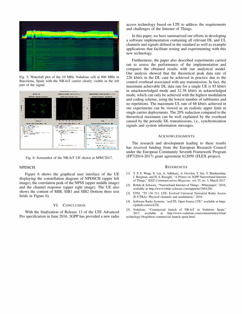
Fig. 5: Waterfall plot of the 10 MHz Vodafone cell at 806 MHz inBarcelona, Spain with the NB-IoT carrier clearly visible in the leftpart of the signal.
Fig. 6: Screenshot of the NB-IoT UE shown at MWC2017.
NPDSCH.
Figure 6 shows the graphical user interface of the UEdisplaying the constellation diagram of NPDSCH (upper leftimage), the correlation peak of the NPSS (upper middle image)and the channel response (upper right image). The UE alsoshows the content of MIB, SIB1 and SIB2 (bottom three textfields in Figure 6).
VI. CONCLUSION
With the finalization of Release 13 of the LTE AdvancedPro specification in June 2016, 3GPP has provided a new radio
access technology based on LTE to address the requirementsand challenges of the Internet of Things.
In this paper, we have summarized our efforts in developinga software implementation containing all relevant DL and ULchannels and signals defined in the standard as well as exampleapplications that facilitate testing and experimenting with thisnew technology.
Furthermore, the paper also described experiments carriedout to assess the performance of the implementation andcompares the obtained results with our analytical model.Our analysis showed that the theoretical peak data rate of226 kbit/s in the DL cant be achieved in practice due to thecontrol overhead associated with any transmission. In fact, themaximum achievable DL data rate for a single UE is 85 kbit/sin unacknowledged mode and 32.38 kbit/s in acknowledgedmode, which can only be achieved with the highest modulationand coding scheme, using the lowest number of subframes andno repetitions. The maximum UL rate of 68 kbit/s achieved inour experiments can be viewed as an realistic upper limit insingle carrier deployments. The 20% reduction compared to thetheoretical maximum can be well explained by the overheadcaused by the periodic DL transmissions, i.e., synchronizationsignals and system information messages.
ACKNOWLEDGMENTS
The research and development leading to these resultshas received funding from the European Research Councilunder the European Community Seventh Framework Program(FP7/2014-2017) grant agreement 612050 (FLEX project).
REFERENCES
[1] Y. P. E. Wang, X. Lin, A. Adhikary, A. Grovlen, Y. Sui, Y. Blankenship,J. Bergman, and H. S. Razaghi, “A Primer on 3GPP Narrowband Internetof Things,” IEEE Communications Magazine, vol. 55, no. 3, March 2017.
[2] Rohde & Schwarz, “Narrowband Internet of Things - Whitepaper,” 2016,available at http://www.rohde-schwarz.com/appnote/1MA266.
[3] ETSI, “TS 136 211: LTE: Evolved Universal Terrestrial Radio Access(E-UTRA): Physical channels and modulation,” 2016.
[4] Software Radio Systems, “srsLTE: Open Source LTE,” available at https://github.com/srsLTE.
[5] Vodafone, “Commercial launch of NB-IoT in Vodafone Spain,”2017, available at http://www.vodafone.com/content/index/what/
technology-blog/nbiot-commercial-launch-spain.html.