implementing fieldbus technology on the ravensthorpe ... · the south west of western australia ......
TRANSCRIPT

Page 1 of 18
Implementing Fieldbus Technology on the
Ravensthorpe Nickel Project
Thorsten Krohn Ravensthorpe Joint Venture, 45 St. Georges Terrace, Perth, WA, 6000
Abstract: In March 2004 BHP Billiton approved the development of the Ravensthorpe Nickel Project at an estimated capital cost of US$1.1 billion. Fieldbus technologies will be implemented on the Ravensthorpe processing plant. Key implementation objectives are to make effective use of fieldbus information in operating and maintenance activities. This requires integration of various systems, as well as adapting work practises. This paper describes the Project’s fieldbus technology decision, the objectives for using fieldbus technology and the implementation strategy employed to realise the objectives.
Keywords: Fieldbus, Maintenance, System Integration
1. Introduction
In March 2004 BHP Billiton approved construction of the Ravensthorpe Nickel Project and the Yabulu Refinery expansion in Northern Queensland. The combined project will produce high quality nickel metal and cobalt for global export markets. The two components of the combined project are:
• Construction of a new mine and mineral processing facility at Ravensthorpe in the South West of Western Australia (Ravensthorpe Nickel Project) to produce a mixed nickel and cobalt hydroxide intermediate product (MHP);
• Expanding QNI Yabulu Refinery near Townsville, North Queensland to process the intermediate product from Ravensthorpe (Yabulu Extension Project).
Foundation Fieldbus End Users Council Australia Inc.
9 Corcoran St Duncraig, WA 6023
P.O. Box Z5546 Perth, WA 6831
Implementing Fieldbus Technology on the Ravensthorpe Nickel Project
Thorsten Krohn Page 2 of 18
Fieldbus technologies have been selected for implementation on the mineral processing facility of the Ravensthorpe Nickel Project. The benefits of the fieldbus technology extend beyond installation cost savings and reduced commissioning times into operations and maintenance excellence. The project’s objectives are to realise these extended benefits.
This paper provides an overview of the Ravensthorpe Nickel Project, explains the Project’s fieldbus technology decision, defines the Fieldbus implementation objectives and the strategy employed to realise these objectives.
2. The Ravensthorpe Nickel Project
2.1. Overview
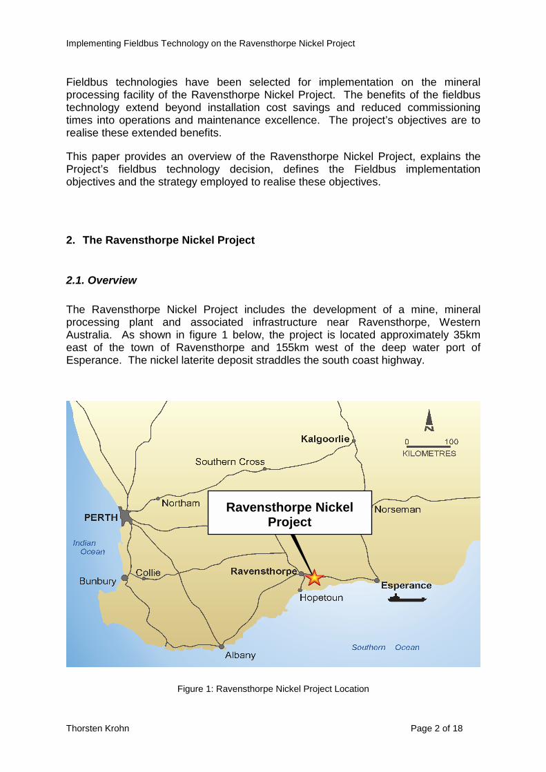
The Ravensthorpe Nickel Project includes the development of a mine, mineral processing plant and associated infrastructure near Ravensthorpe, Western Australia. As shown in figure 1 below, the project is located approximately 35km east of the town of Ravensthorpe and 155km west of the deep water port of Esperance. The nickel laterite deposit straddles the south coast highway.
Figure 1: Ravensthorpe Nickel Project Location
Ravensthorpe Nickel Project

Implementing Fieldbus Technology on the Ravensthorpe Nickel Project
Thorsten Krohn Page 3 of 18
2.2. Process Flow Sheet
The project involves open pit mining from three adjacent nickel laterite ore bodies, ore beneficiation plants and a hydrometallurgical process plant to treat both limonite and saprolite ores to produce up to 50,000 tonnes p.a. of contained nickel and 1400 tonnes p.a. of contained cobalt in MHP.
Ore Beneficiation Plants
The Ravensthorpe ore body is distinctive in that it has a high silica content which enables the limonite ore to be upgraded to almost twice the mined grade through a beneficiation process – a simple scrubbing and screening process to remove the barren, hard silica. The saprolite ore also upgrades but to a lesser extent. Limonite and saprolite ores will be upgraded separately in two purpose-built beneficiation circuits, one of which is shown in figure 2 below, thereby increasing the nickel grade of the ore prior to the hydrometallurgical plant.
Figure 2: Ore Beneficiation Process Flow Sheet

Implementing Fieldbus Technology on the Ravensthorpe Nickel Project
Thorsten Krohn Page 4 of 18
Hydrometallurgical Plant
The project’s hydrometallurgical flow sheet, shown in figure 3 below, is a combination of pressure acid leach (PAL) and atmospheric leach (AL) processes, called the Enhanced Pressure Acid Leach (EPAL) process.
The EPAL process entails separate mining, stockpiling and beneficiation of limonite (high iron, low magnesium and calcium, upper levels) ore and saprolite (low iron, high magnesium, deeper levels) ore. The limonite ore is treated by PAL, whilst the saprolite is treated by AL using the PAL discharge and additional acid.
The process downstream of the leaching circuit uses the proven Cawse Nickel Laterite Process flow sheet with partial neutralisation, followed by separation of the barren tailings from the nickel bearing solution, further impurity removal and precipitation of MHP. This intermediate product is then transported to the QNI Yabulu Refinery for further processing to produce high quality nickel metal and cobalt for export to world markets.
Figure 3: Hydrometallurgical Process Flow Sheet

Implementing Fieldbus Technology on the Ravensthorpe Nickel Project
Thorsten Krohn Page 5 of 18
2.3. Utilities and Reagents
Sulphuric Acid Plant
Sulphur prill, a granular form of sulphur, is imported via the Port of Esperance. Sulphuric acid is produced from this sulphur prill for use in the acid leach parts of the plant. Waste heat is used to produce steam, which is then used for power generation.
Power and Steam Generation
The Power and Steam Generation Plant is made up of three steam turbines, three package boilers, diesel generators and mechanical and electrical equipment. Steam from the Sulphuric Acid plant will be used in the steam turbines to generate electrical power. The package boilers provide supplemental steam for start-up purposes. De-superheated steam is produced for use in various parts of the plant.
Water
Seawater will be piped from the Southern Ocean and pumped to the site via a 46km long pipeline system. Seawater will be desalinated on site to produce freshwater for steam production while the waste brine stream will be used in the beneficiation plants.
Limestone and Magnesia
Limestone and magnesia are required for the process. Limestone is mined from a local quarry and magnesia is shipped from Queensland and China.
3. The Fieldbus Decision
3.1. Why Fieldbus ?
The decision to use fieldbus technology on the Ravensthorpe Nickel Project was taken because the technology supports the project’s maintenance strategy, supports the project’s cost and schedule objectives and because the technology offers potential soft benefits. Each of these aspects is described below.
Maintenance Strategy
The maintenance strategy for the project includes the following two points:

Implementing Fieldbus Technology on the Ravensthorpe Nickel Project
Thorsten Krohn Page 6 of 18
• Emphasis will be placed on condition monitoring and the use of non-intrusive inspections and measurements where this is possible, to avoid wastage associated with removing equipment only to find that it was not necessary; and
• Maximum use will be made of digital technology for remote monitoring where this is a part of the equipment design.
Fieldbus supports these two aspects from the projects’ maintenance strategy.
Project Objectives
Project cost and schedule objectives are, like most other projects, simple. Capital cost is to be within the feasibility study estimate and process commissioning is to start by the agreed date.
Recent studies suggest that the overall fieldbus installation costs are equivalent to, or less than traditional installations. Rather than re-investigate comparative costs, the project made the fieldbus decision based on this information. Fieldbus costs are therefore embedded in the feasibility study estimate.
Commissioning time for fieldbus based instrumentation is claimed to be significantly less than that required for traditional (4-20 mA) based instrumentation. As described for the costs above, the project accepted these claims and made the fieldbus decision on this basis.
Soft Benefits
The project has to compete for technical resources both during the design and construction phase, and during the commissioning and operational phase. Fieldbus technology provides soft benefits of being able to attract people to the project in a competitive labour market.
3.2. Which Fieldbus ?
Fieldbus technologies are applicable to both electrical devices (motor protection relays, variable speed drives, etc.) and process instrumentation (instruments and control valves). Technologies were selected by defining the project context and then defining requirements within this project context.
Project Context
The project context relevant to fieldbus selection can be summarised as follows:
• Process Flow Sheet. The process downstream of the leaching circuit is single stream with large flows. Similarly, the acid plant is single stream and produces the steam required for power generation. Shutdowns in these

Implementing Fieldbus Technology on the Ravensthorpe Nickel Project
Thorsten Krohn Page 7 of 18
areas will ultimately shutdown the entire plant. A shutdown of either pressure acid leach process train not only causes lost production, but can also be costly from a maintenance perspective.
• Instrumentation to Electrical Device Ratio. The ratio of analogue instrumentation to electrical motors for the hydrometallurgical part of the plant is approximately 65% to 35%. The ratio for the Sulphuric Acid Plant and Power Plant is expected to be more biased towards instrumentation. Technology can be chosen on merit rather than rationalisation.
• Final Control Elements. Approximately 50% of control loops on the main plant will be performed by variable speed drives. This impacts field based control considerations.
• Short Field Cable Runs. The plant layout has electrical substations located next to each plant area. The control system has been designed to have control processors and associated input/out units installed in each substation. Cable runs from field devices to control system input/output units will therefore be relatively short.
• Hazardous Areas. The plant has a minimal number of hazardous areas with respect to explosive gas or dust atmospheres. The quantity of instruments in these areas are minimal and therefore do not impact the fieldbus decision.
Project Requirements
The project has defined a set of requirements that guide the implementation of information systems and information technology on the project. Some of these requirements were applicable in the selection of fieldbus technology, namely:
• Availability;
• Use proven technology;
• Use a minimised set of different technologies; and
• Consider recent project experience.
Recent project experience has shown that cabling and interoperability are significant issues when installing and commissioning fieldbus networks.
Fieldbus Selection for Electrical Devices
The project considered the following as practical options:
• Profibus DP;
• DeviceNet; and

Implementing Fieldbus Technology on the Ravensthorpe Nickel Project
Thorsten Krohn Page 8 of 18
• ASi Bus.
The key reasons for selecting Profibus DP were:
• Recent Experience. The motor control and protection devices selected for the study have been successfully applied in recent large Western Australian and worldwide projects. These devices represent the majority of fieldbus connected electrical devices and therefore had significant influence on the technology decision; and
• Availability. Cost effective dual redundant control system interface cards are now commonly available items.
Fieldbus Selection for Instrumentation
The project considered the following as practical options:
• FOUNDATION Fieldbus H1; and
• Profibus PA.
The key reasons for selecting FOUNDATION Fieldbus H1 were:
• Availability. Cost effective dual redundant control system interface cards and power conditioning modules are now commonly available items;
• Short Circuit Protection. Cost effective devices that limit short circuit current on spurs are now commonly available items; and
• Systems Support. The systems considered for project’s control system in general provided better functional support for FOUNDATION Fieldbus.
Fieldbus Selection for On/Off Control Valves
FOUNDATION Fieldbus is now being considered for on/off control valves where it is cost effective to do so. FOUNDATION Fieldbus infrastructure will exist in all plant areas and therefore could be used to connect on/off valve to the control system. This is practical and cost effective in plants areas with relatively few, sparsely distributed, on/off valves. However, this is not cost effective in some plant areas, such as the power plant, due to the quantity of on/off valves and their close proximity to one another. In such cases discrete input/outputs will be used.

Implementing Fieldbus Technology on the Ravensthorpe Nickel Project
Thorsten Krohn Page 9 of 18
4. Fieldbus Implementation
Fieldbus networks are simply infrastructure that enables devices to be connected to a plant’s control system. While this infrastructure is important, it is the functionality offered by fieldbus that provides the more significant and long-term operational benefits.
One of the project’s fieldbus implementation objectives is to realise installation cost and schedule benefits. However, the key objective is to implement fieldbus functionality in operations and maintenance aspects of the plant.
The strategy employed to realise these objectives, fieldbus infrastructure as well as fieldbus functionality in operations and maintenance activities are discussed in this section.
4.1. Fieldbus Implementation Strategy
The strategy employed to implement fieldbus on the project can be summarised by the following points:
• Define objectives;
• Establish and maintain the team;
o Initial training; and
o Ongoing familiarisation;
• Select PCS supplier early;
• Develop plans, specifications and procedures. These must be:
o Project specific;
o Based on Standards and Guidelines;
o Consider past experiences and best practise;
o Validated using the development system; and
o Verified by domain experts;
• Develop control system software in one offsite location;
• Perform complete systems integration test in one offsite location; and
• Prepare standard operating procedures (SOPs).
Implementing Fieldbus Technology on the Ravensthorpe Nickel Project
Thorsten Krohn Page 10 of 18
While most of the above points are self explanatory, two points are worth clarification. Firstly, the team means the entire control and instrumentation team. All require training and ongoing familiarisation will be done using the project’s development system. Secondly, the adoption of relevant standards is seen as crucial to a successful implementation of technology. Some of the standards adopted for the project are listed in section 7 below.
4.2. Fieldbus Infrastructure
The following fieldbus infrastructure objectives were set for the project:
• Minimise cabling;
• Minimise commissioning time; and
• Keep it simple.
Topologies for FOUNDATION Fieldbus and for Profibus DP segments that meet these objectives have been defined and are described below.
FOUNDATION Fieldbus H1 Segment Topology
A typical foundation fieldbus H1 segment for the project is shown in figure 4. This arrangement is based on the FOUNDATION Fieldbus System Engineering Guidelines (AG-181) and meets the projects requirements for availability and simplicity. Each segment has the following salient features:
• Dual redundant control system H1 interface card;
• Dual redundant H1 segment power conditioner with built-in terminator;
• Short circuit segment protectors with built-in terminators in the field; and
• Termination of up to twelve devices per segment.
Simplex control system interface cards may be used in plant areas where availability is not an essential criteria, e.g. crushing plants.
All cables will meet FOUNDATION Fieldbus Type A cable specifications and will be terminated on screw terminals. Trunk cable may be either single pair or multi pair cable. Multi pair cable will have individual and overall screens. Spur cable will be single pair cable.

Implementing Fieldbus Technology on the Ravensthorpe Nickel Project
Thorsten Krohn Page 11 of 18
Figure 4: FOUNDATION Fieldbus H1 Segment Topology
Profibus DP Segment
A typical Profibus DP segment for the project is shown in figure 5. This arrangement is based on recent project experience and has the following salient features:
• Dual redundant control system Profibus DP interface card with built-in terminator;
• Connection of up to 30 devices per segment; and
• Powered terminator at the end of each segment.
Simplex control system interface cards may be used in plant areas where availability is not an essential criteria, e.g. crushing plants.
All cables will meet EN50170-2-2:1996 cable specifications for communication up to 12Mbaud and will be terminated on screw terminals.

Implementing Fieldbus Technology on the Ravensthorpe Nickel Project
Thorsten Krohn Page 12 of 18
Figure 5: Profibus DP Segment Topology
4.3. Fieldbus and Operations
Abnormal situation prevention principles will be applied in the design of the control system, with specific focus on the following three aspects of operations:
• Alarm Management;
• Control Strategies; and
• Operator Interface.
Fieldbus devices generate device alarm and events, referred to as alerts. An example of a device alert may be a temperature transmitter detecting that its temperature element is out of tolerance limits. These alerts are generated in addition to the alarms generated by a plant’s monitoring and control functions. The project objective is to use fieldbus device alerts effectively in each of the above aspects of operations.

Implementing Fieldbus Technology on the Ravensthorpe Nickel Project
Thorsten Krohn Page 13 of 18
Device Alerts and Alarm Management
Device alerts are numerous during plant commissioning, and can overload operators during normal operation. An alarm management strategy that, in addition to rationalising process alarms, also rationalises device alerts is therefore a necessary part of any fieldbus implementation. This philosophy has been adopted by the project, and the following device alert management objectives have been established:
• Prioritise all device alerts;
• Notify operators of a device alert only if the alert affects the process;
• Direct all devices alerts to control system maintenance stations; and
• Keep historical records of all device alerts.
Device Alerts in Control Strategies
Fieldbus devices have the ability to define the status of process variables. As an example, if the sensing element of a transmitter has failed, then its process variable may be marked as “bad”. However, before the sensing element fails a transmitter can determine that the sensing element is out of specification and mark its process variable as “uncertain”.
Control strategies can be configured to act on the status of a process variable. A typical example is for a controller to hold its output when the process variable status is “bad”. However, the projects objective with respect to control strategies is to also define action when the process variable is “uncertain”.
Device Alert Notification at the Operator Interface
A project specific operator interface design specification will be produced. This will adopt human factor guidelines and principles to improve operator effectiveness.
Object visualisation guidelines exist for display process variables with “bad” status. The project objective is to extend these guidelines to the display of process variables with “uncertain” or other status.
4.4. Fieldbus and Maintenance
The project objective is to use fieldbus device functionality in condition based and predictive maintenance strategies. To realise this objective requires effective integration of the field device management system and the maintenance management system.

Implementing Fieldbus Technology on the Ravensthorpe Nickel Project
Thorsten Krohn Page 14 of 18
Project Specific Maintenance Definitions
The project has defined two categories of maintenance, namely proactive and reactive. Reactive maintenance occurs in response to equipment break-down, while proactive maintenance occurs before equipment break-down.
Three types of proactive maintenance are defined, namely preventative, predictive and condition based maintenance. Preventative maintenance generally occurs well before equipment break-down, either regularly or at opportune moments. Predictive maintenance is based on historical information and occurs as close as practical before equipment break-down. Condition based maintenance occurs when equipment is no longer performing within specification.
Condition Based Maintenance
Condition based maintenance is one part of the plant’s proactive maintenance strategies. As far as fieldbus devices are concerned, an “out of specification” condition will initiate maintenance requests. Appropriate fieldbus device alerts will be used as the initiators.
Figure 6 shows the Functional Enterprise-Control Interface Model from Part 1 of the ANSI/ISA 95 standard. One data flow defined in the standard, and highlighted in figure 6, is the maintenance request from “Production Control” to “Maintenance Management”. These maintenance requests will be automatically initiated by the field device management system.

Implementing Fieldbus Technology on the Ravensthorpe Nickel Project
Thorsten Krohn Page 15 of 18
Figure 6: ISA 95 Part 1 – Functional Enterprise-Control Interface Model
Predictive Maintenance
Predictive maintenance is another part of the plant’s proactive maintenance strategy. However, in order to be able to accurately predict the future, knowledge of the past is required. Since this is a greenfield facility, information will be collected for future analysis and formulation of a predictive maintenance strategy.
The scenario that will be implemented on the project is shown in figure 7, the Activity Model of Maintenance Management from Part 3 of the ANSI/ISA 95 standard.

Implementing Fieldbus Technology on the Ravensthorpe Nickel Project
Thorsten Krohn Page 16 of 18
Figure 7: ISA 95 Part 3 – Activity Model of Maintenance Management
System Integration
A field device management system will be used to manage all fieldbus devices. This system must be integrated with other systems so that condition based and predictive maintenance scenarios described above can be implemented. Integration will be performed using one of the following standards:
• XML; and
• OPC
A XML (eXtensible Mark-up Language) based system integration platform will be used to manage data transactions between all the plant’s information systems. The World Batch Forum has defined a set of ISA 95 based XML schemas, collectively termed Business to Manufacturing Mark-up Language (B2MML). These B2MML schemas will be used as the basis for transactions between the Production / Process systems and the Business systems. More specifically, maintenance request data

Implementing Fieldbus Technology on the Ravensthorpe Nickel Project
Thorsten Krohn Page 17 of 18
flow is uniquely identified in ISA 95 Part 1, and the associated B2MML schema will be used as the basis for maintenance requests.
The OPC (Open Connectivity) specification for Alarms and Events will be used to integrate the field device management system with the Plant Historian. All device alerts will be captured in the Historian. This data can then be analysed in future and a predictive maintenance strategy formulated based on historical information.
5. Summary
The benefits of Fieldbus extend beyond installation cost savings and reduced commissioning times into operations and maintenance excellence. The Ravensthorpe Nickel Project, being a greenfield project, presents a unique opportunity to realise these extended benefits.
The project has recognised this opportunity, has defined realistic fieldbus implementation objectives and has put in place a fieldbus implementation strategy to realise these objectives. The project is at an early stage of design and there is long way to go. However, with the committed and enthusiastic team we have in place, the support of the Manufacturers and Suppliers of fieldbus equipment and collaboration with the end user community, we believe that we will realise if not exceed our objectives and reap the rewards in the future.
6. References
ARC Report, “Best Practises for Maximising the Value of Fieldbus Installations”, by Larry O’Brien, January 2004.
ARC Insight, “Fieldbus End User Adoption Tends to Show Growing Acceptance”, by Larry O’Brien, July 2003.
BHP Billiton, “The Ravensthorpe Nickel Project and Yabulu Refinery Expansion Overview”, www.bhpbilliton.com, March 2004.
Fieldbus Foundation, FOUNDATION Fieldbus System Engineering Guidelines, AG-181.
Hans Rill, “The Sakhalin II Project”, Presentation at Interkama 2004.

Implementing Fieldbus Technology on the Ravensthorpe Nickel Project
Thorsten Krohn Page 18 of 18
7. Partial List of Standards Adopted on the Project
FOUNDATION Fieldbus Implementation
AG-181, “FOUNDATION Fieldbus System Engineering Guidelines”
Operator Interface and Alarm System Design
ANSI/HFES 200, “Ergonomic Requirements for Software User Interfaces”
ANSI/ISA-88.01, “Batch Control, Part 1; Models and Terminology”
EEMUA 191, “Alarm Systems - A Guide to Design, Management & Procurement“
EEMUA 201, “Plant Control Desks and the Human-Computer Interface: A Guide to Design, Operational and Human-Computer Interface Issues”
ISO 9241, "Ergonomic Requirements for Office Work with Visual Display Terminals”
System Integration
ANSI/ISA-95.00.01, “Enterprise-Control System Integration, Part 1: Models and Terminology”
ANSI/ISA-95.00.02, “Enterprise-Control System Integration, Part 2: Object Models and Attributes”
ANSI/ISA Draft 95.00.03, “Enterprise-Control System Integration, Part 3: Models of Manufacturing Operation Management”
ANSI/ISA Draft 95.00.04, “Enterprise-Control System Integration, Part 4: Object Models and Attributes of Manufacturing Operations Management Activities”
ANSI/ISA Draft 95.00.05, “Enterprise-Control System Integration, Part 5: Business to Manufacturing Transactions”